hp 1910 gigabit ethernet switch series - viakom 1910_manual.pdf · hp 1910 gigabit ethernet switch...
TRANSCRIPT

HP 1910 Gigabit Ethernet Switch Series Getting Started Guide
Part number: 5998-2236
Document version: 6W103-20131118

Legal and notice information
© Copyright 2013 Hewlett-Packard Development Company, L.P.
No part of this documentation may be reproduced or transmitted in any form or by any means without prior written consent of Hewlett-Packard Development Company, L.P.
The information contained herein is subject to change without notice.
HEWLETT-PACKARD COMPANY MAKES NO WARRANTY OF ANY KIND WITH REGARD TO THIS MATERIAL, INCLUDING, BUT NOT LIMITED TO, THE IMPLIED WARRANTIES OF MERCHANTABILITY AND FITNESS FOR A PARTICULAR PURPOSE. Hewlett-Packard shall not be liable for errors contained herein or for incidental or consequential damages in connection with the furnishing, performance, or use of this material.
The only warranties for HP products and services are set forth in the express warranty statements accompanying such products and services. Nothing herein should be construed as constituting an additional warranty. HP shall not be liable for technical or editorial errors or omissions contained herein.
i
Contents
Product overview ·························································································································································· 1 V1910-16G panel views ················································································································································· 2 V1910-24G panel views ················································································································································· 2 V1910-48G panel views ················································································································································· 3 V1910-24G-PoE (170W) panel views ··························································································································· 3 V1910-24G-PoE (365W) panel views ··························································································································· 4 1910-8G panel views ······················································································································································ 4 1910-8G-PoE+ (65W) panel views ································································································································ 5 1910-8G-PoE+ (180W) panel views ······························································································································ 6
Preparing for installation ············································································································································· 7 Safety recommendations ·················································································································································· 7 Examining the installation site ········································································································································· 7
Temperature/humidity ············································································································································· 7 Cleanness ·································································································································································· 8 EMI ············································································································································································· 8 Laser safety ································································································································································ 8
Installation tools ································································································································································· 9
Installing the switch ···················································································································································· 10 Installing the switch in a 19-inch rack ·························································································································· 10
Mounting brackets and mounting positions ········································································································ 11 Attaching the mounting brackets to the switch chassis ······················································································ 12 Rack-mounting the switch ······································································································································ 14
Mounting the switch on a workbench ·························································································································· 17 Mounting the switch on a wall ····································································································································· 17 Grounding the switch ···················································································································································· 19
Grounding the switch with a grounding strip ····································································································· 19 Grounding the switch with a grounding conductor buried in the earth ground ············································· 21 Grounding the switch by using the AC power cord ·························································································· 22
Connecting the power cord ·········································································································································· 22 Connecting the AC power cord ··························································································································· 23 Connecting the switch to a –52 to –55 VDC output RPS ·················································································· 23
Verifying the installation ················································································································································ 24
Accessing the switch for the first time ······················································································································· 25 Setting up the configuration environment ···················································································································· 25 Connecting the console cable ······································································································································ 25
Console cable ························································································································································ 25 Connection procedure ·········································································································································· 25
Setting terminal parameters ·········································································································································· 26 Powering on the switch·················································································································································· 29
Verification before power-on ······························································································································· 29 Powering on the switch ········································································································································· 29 Changing the startup mode ·································································································································· 31
Maintenance and troubleshooting ···························································································································· 33 Password loss ································································································································································· 33
Console login password loss ······························································································································· 33 Boot ROM password loss ····································································································································· 33
Power supply failure ······················································································································································ 33

ii
Configuration terminal problems ·································································································································· 34
Support and other resources ····································································································································· 36 Contacting HP ································································································································································ 36
Subscription service ·············································································································································· 36 Related information ························································································································································ 36
Documents ······························································································································································ 36 Websites ································································································································································· 36
Conventions ···································································································································································· 37
Appendix A Technical specifications ························································································································ 39 Physical specifications ··················································································································································· 39
Chassis dimensions and weights ························································································································· 39 Ports and interface card slots ······························································································································· 39
Environmental specifications ········································································································································· 39 Power specifications ······················································································································································ 40
Power input types ·················································································································································· 40 AC input voltage specifications ··························································································································· 40 RPS DC input voltage specifications and RPS compatibility ············································································· 40 Power consumption specifications for non-PoE switches ··················································································· 40 Power consumption specifications for PoE switches ·························································································· 40
Cooling system ······························································································································································· 41
Appendix B FRUs and compatibility matrixes ·········································································································· 42 SFP transceiver modules and SFP Stacking Kit ··········································································································· 42
Appendix C Ports and LEDs ······································································································································ 44 Ports ················································································································································································· 44
Console port ·························································································································································· 44 10/100/1000Base-T Ethernet port ···················································································································· 44 SFP port ·································································································································································· 44
LEDs ················································································································································································· 45 Power LED ······························································································································································ 45 RPS status LED ························································································································································ 45 Port mode LED ························································································································································ 45 10/100/1000Base-T Ethernet port LED ············································································································· 46 1000Base-X SFP port LED ····································································································································· 47
Index ··········································································································································································· 48
1
Product overview
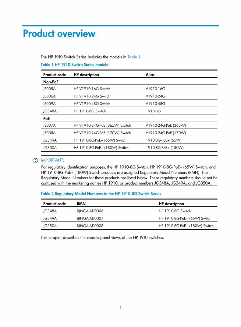
The HP 1910 Switch Series includes the models in Table 1.
Table 1 HP 1910 Switch Series models
Product code HP description Alias
Non-PoE
JE005A HP V1910-16G Switch V1910-16G
JE006A HP V1910-24G Switch V1910-24G
JE009A HP V1910-48G Switch V1910-48G
JG348A HP 1910-8G Switch 1910-8G
PoE
JE007A HP V1910-24G-PoE (365W) Switch V1910-24G-PoE (365W)
JE008A HP V1910-24G-PoE (170W) Switch V1910-24G-PoE (170W)
JG349A HP 1910-8G-PoE+ (65W) Switch 1910-8G-PoE+ (65W)
JG350A HP 1910-8G-PoE+ (180W) Switch 1910-8G-PoE+ (180W)
IMPORTANT:
For regulatory identification purposes, the HP 1910-8G Switch, HP 1910-8G-PoE+ (65W) Switch, and HP 1910-8G-PoE+ (180W) Switch products are assigned Regulatory Model Numbers (RMN). The Regulatory Model Numbers for these products are listed below. These regulatory numbers should not beconfused with the marketing names HP 1910, or product numbers JG348A, JG349A, and JG350A.
Table 2 Regulatory Model Numbers in the HP 1910-8G Switch Series
Product code RMN HP description
JG348A BJNGA-AD0006 HP 1910-8G Switch
JG349A BJNGA-AD0007 HP 1910-8G-PoE+ (65W) Switch
JG350A BJNGA-AD0008 HP 1910-8G-PoE+ (180W) Switch
This chapter describes the chassis panel views of the HP 1910 switches.

2
V1910-16G panel views Figure 1 Front panel
(1) 10/100/1000Base-T auto-sensing Ethernet port (2) 1000Base-X SFP port (3) Console port (4) Port LED (5) Power LED (Power)
Figure 2 Rear panel
(1) AC-input power receptacle (2) Grounding screw
V1910-24G panel views Figure 3 Front panel
(1) 10/100/1000Base-T auto-sensing Ethernet port (2) 1000Base-X SFP port (3) Console port (4) Port LED (5) Power LED (Power)
Figure 4 Rear panel
(1) AC-input power receptacle (2) Grounding screw
1 2

3
V1910-48G panel views Figure 5 Front panel
(1) 10/100/1000Base-T auto-sensing Ethernet port (2) 10/100/1000Base-T Ethernet port LED (3) Console port (4) Power LED (Power) (5) 1000Base-X SFP port (6) 1000Base-X SFP port LED
Figure 6 Rear panel
(1) AC-input power receptacle (2) Grounding screw
V1910-24G-PoE (170W) panel views Figure 7 Front panel
(1) 10/100/1000Base-T auto-sensing Ethernet port (2) Port LED mode switching button (3) Port LED (4) Power LED (Power) (5) Port mode LED (6) Console port (7) 1000Base-X SFP port
4
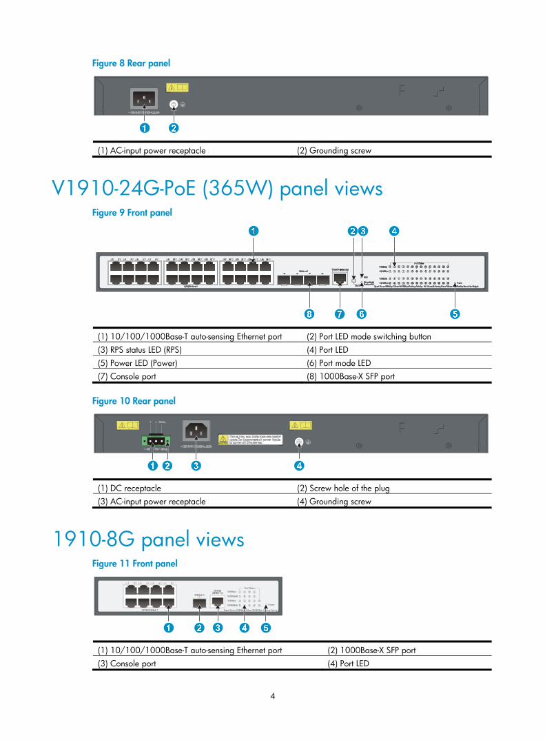
Figure 8 Rear panel
(1) AC-input power receptacle (2) Grounding screw
V1910-24G-PoE (365W) panel views Figure 9 Front panel
(1) 10/100/1000Base-T auto-sensing Ethernet port (2) Port LED mode switching button (3) RPS status LED (RPS) (4) Port LED (5) Power LED (Power) (6) Port mode LED (7) Console port (8) 1000Base-X SFP port
Figure 10 Rear panel
(1) DC receptacle (2) Screw hole of the plug (3) AC-input power receptacle (4) Grounding screw
1910-8G panel views Figure 11 Front panel
(1) 10/100/1000Base-T auto-sensing Ethernet port (2) 1000Base-X SFP port (3) Console port (4) Port LED
5
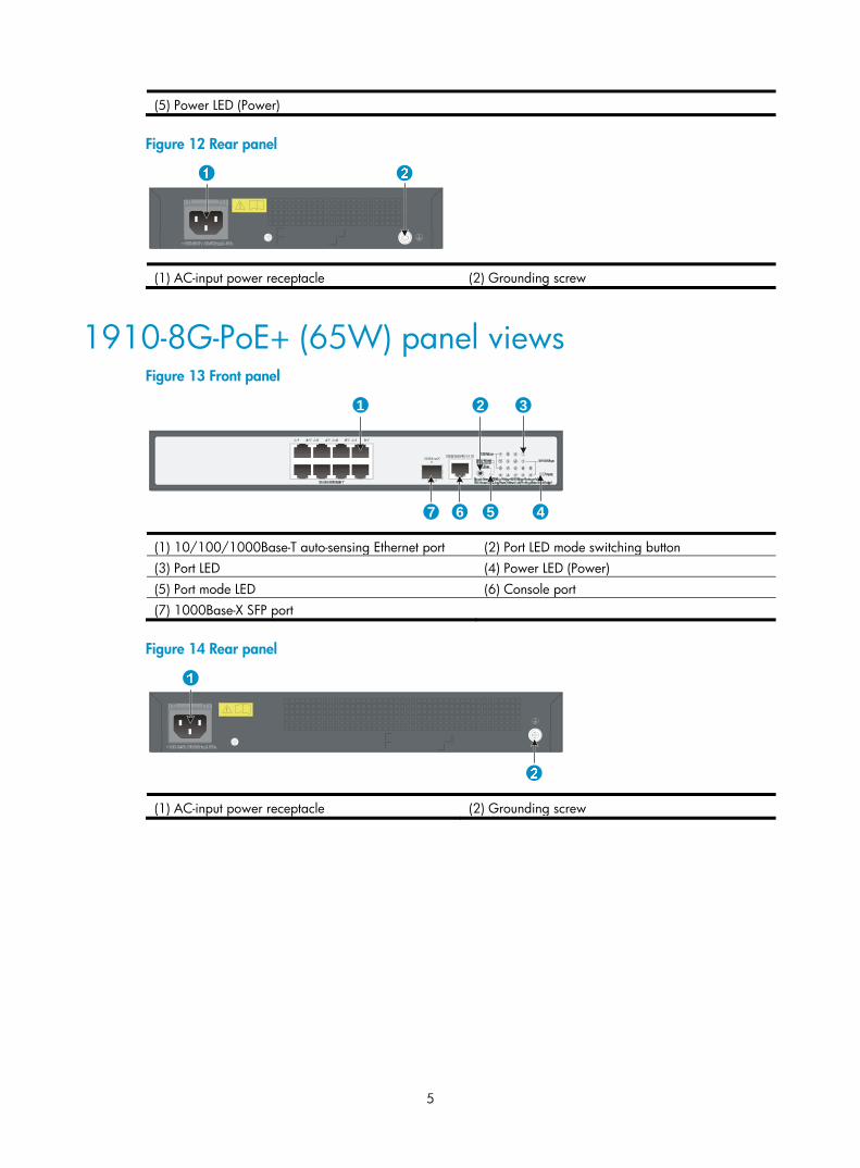
(5) Power LED (Power)
Figure 12 Rear panel
(1) AC-input power receptacle (2) Grounding screw
1910-8G-PoE+ (65W) panel views Figure 13 Front panel
(1) 10/100/1000Base-T auto-sensing Ethernet port (2) Port LED mode switching button (3) Port LED (4) Power LED (Power) (5) Port mode LED (6) Console port (7) 1000Base-X SFP port
Figure 14 Rear panel
(1) AC-input power receptacle (2) Grounding screw
45
1 2 3
67

6
1910-8G-PoE+ (180W) panel views Figure 15 Front panel
(1) 10/100/1000Base-T auto-sensing Ethernet port (2) Port LED mode switching button (3) Port LED (4) Power LED (Power) (5) Port mode LED (6) Console port (7) 1000Base-X SFP port
Figure 16 Rear panel
(1) AC-input power receptacle (2) Grounding screw
7
Preparing for installation
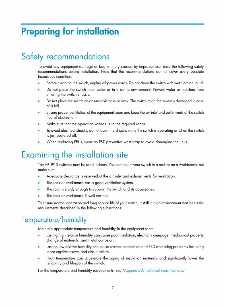
Safety recommendations To avoid any equipment damage or bodily injury caused by improper use, read the following safety recommendations before installation. Note that the recommendations do not cover every possible hazardous condition.
• Before cleaning the switch, unplug all power cords. Do not clean the switch with wet cloth or liquid.
• Do not place the switch near water or in a damp environment. Prevent water or moisture from entering the switch chassis.
• Do not place the switch on an unstable case or desk. The switch might be severely damaged in case of a fall.
• Ensure proper ventilation of the equipment room and keep the air inlet and outlet vents of the switch free of obstruction.
• Make sure that the operating voltage is in the required range.
• To avoid electrical shocks, do not open the chassis while the switch is operating or when the switch is just powered off.
• When replacing FRUs, wear an ESD-preventive wrist strap to avoid damaging the units.
Examining the installation site The HP 1910 switches must be used indoors. You can mount your switch in a rack or on a workbench, but make sure:
• Adequate clearance is reserved at the air inlet and exhaust vents for ventilation.
• The rack or workbench has a good ventilation system.
• The rack is sturdy enough to support the switch and its accessories.
• The rack or workbench is well earthed.
To ensure normal operation and long service life of your switch, install it in an environment that meets the requirements described in the following subsections.
Temperature/humidity Maintain appropriate temperature and humidity in the equipment room.
• Lasting high relative humidity can cause poor insulation, electricity creepage, mechanical property change of materials, and metal corrosion.
• Lasting low relative humidity can cause washer contraction and ESD and bring problems including loose captive screws and circuit failure.
• High temperature can accelerate the aging of insulation materials and significantly lower the reliability and lifespan of the switch.
For the temperature and humidity requirements, see “Appendix A Technical specifications.”

8
Cleanness Dust buildup on the chassis may result in electrostatic adsorption, which causes poor contact of metal components and contact points, especially when indoor relative humidity is low. In the worst case, electrostatic adsorption can cause communication failure.
Table 3 Dust concentration limit in the equipment room
Substance Concentration limit (particles/m³)
Dust ≤ 3 x 10⁴ (no visible dust on the tabletop over three days)
NOTE:
Dust diameter ≥ 5 μm
The equipment room must also meet strict limits on salts, acids, and sulfides to eliminate corrosion and premature aging of components, as shown in Table 4.
Table 4 Harmful gas limits in the equipment room
Gas Maximum concentration (mg/m3)
SO2 0.2
H2S 0.006
NH3 0.05
Cl2 0.01
EMI All electromagnetic interference (EMI) sources, from outside or inside of the switch and application system, adversely affect the switch in a conduction pattern of capacitance coupling, inductance coupling, electromagnetic wave radiation, or common impedance (including the grounding system) coupling. To prevent EMI, take the following actions:
• If AC power is used, use a single-phase three-wire power receptacle with protection earth (PE) to filter interference from the power grid.
• Keep the switch far away from radio transmitting stations, radar stations, and high-frequency devices.
• Use electromagnetic shielding, for example, shielded interface cables, when necessary.
• Route interface cables only indoors to prevent signal ports from getting damaged by overvoltage or overcurrent caused by lightning strikes.
Laser safety The HP 1910 switches are Class 1 laser devices.
WARNING!
Do not stare into any fiber port when the switch has power. The laser light emitted from the optical fiber may hurt your eyes.
9
Installation tools • Flathead screwdriver
• Phillips screwdriver
• Needle-nose pliers
• Wire-stripping pliers
• Diagonal pliers
• ESD-preventive wrist strap
• Blow dryer
All these installation tools are user supplied.
10
Installing the switch
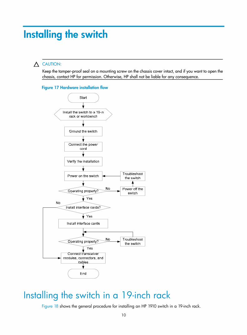
CAUTION:
Keep the tamper-proof seal on a mounting screw on the chassis cover intact, and if you want to open thechassis, contact HP for permission. Otherwise, HP shall not be liable for any consequence.
Figure 17 Hardware installation flow
Installing the switch in a 19-inch rack Figure 18 shows the general procedure for installing an HP 1910 switch in a 19-inch rack.
11
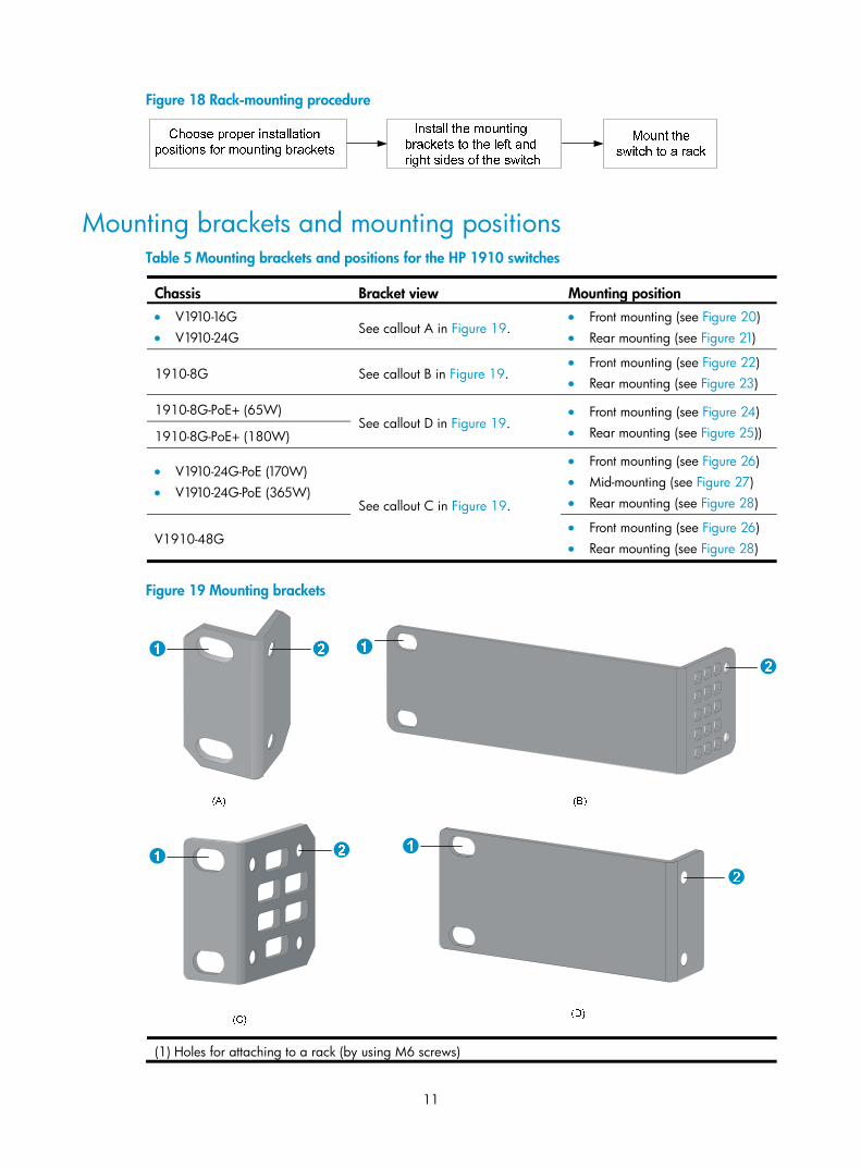
Figure 18 Rack-mounting procedure
Mounting brackets and mounting positions Table 5 Mounting brackets and positions for the HP 1910 switches
Chassis Bracket view Mounting position • V1910-16G • V1910-24G
See callout A in Figure 19. • Front mounting (see Figure 20) • Rear mounting (see Figure 21)
1910-8G See callout B in Figure 19. • Front mounting (see Figure 22) • Rear mounting (see Figure 23)
1910-8G-PoE+ (65W) See callout D in Figure 19.
• Front mounting (see Figure 24) • Rear mounting (see Figure 25)) 1910-8G-PoE+ (180W)
• V1910-24G-PoE (170W) • V1910-24G-PoE (365W)
See callout C in Figure 19.
• Front mounting (see Figure 26) • Mid-mounting (see Figure 27) • Rear mounting (see Figure 28)
V1910-48G • Front mounting (see Figure 26) • Rear mounting (see Figure 28)
Figure 19 Mounting brackets
(1) Holes for attaching to a rack (by using M6 screws)
12
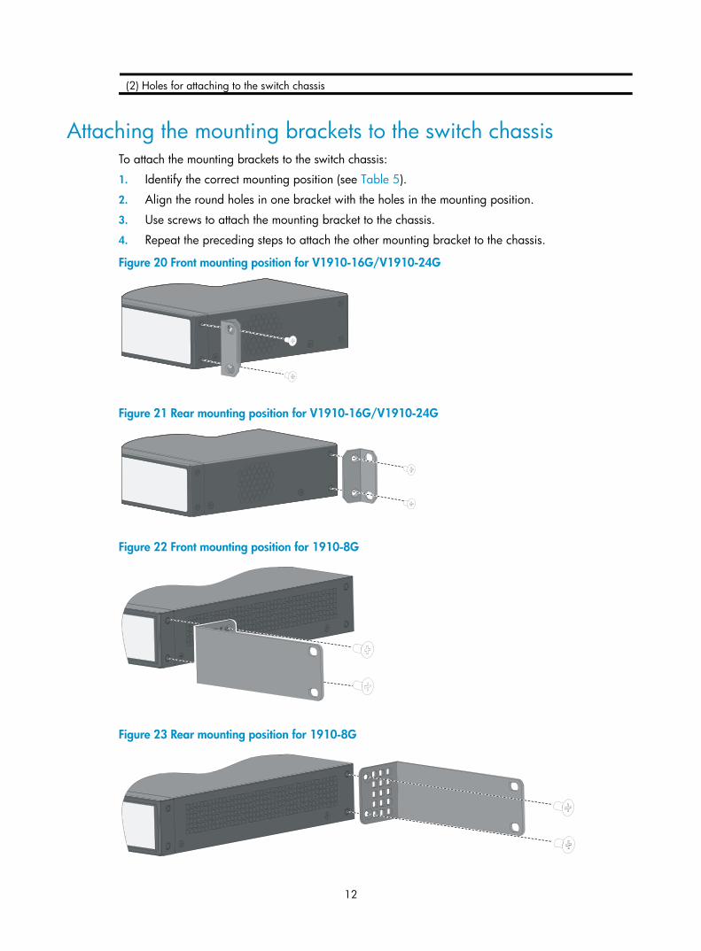
(2) Holes for attaching to the switch chassis
Attaching the mounting brackets to the switch chassis To attach the mounting brackets to the switch chassis:
1. Identify the correct mounting position (see Table 5).
2. Align the round holes in one bracket with the holes in the mounting position.
3. Use screws to attach the mounting bracket to the chassis.
4. Repeat the preceding steps to attach the other mounting bracket to the chassis.
Figure 20 Front mounting position for V1910-16G/V1910-24G
Figure 21 Rear mounting position for V1910-16G/V1910-24G
Figure 22 Front mounting position for 1910-8G
Figure 23 Rear mounting position for 1910-8G

13
Figure 24 Front mounting position for 1910-8G-PoE+ (65W)/1910-8G-PoE+ (180W)
Figure 25 Rear mounting position for 1910-8G-PoE+ (65W)/1910-8G-PoE+ (180W)
Figure 26 Front mounting position for V1910-24G-PoE (170W)/V1910-24G-PoE (365W)/V1910-48G
Figure 27 Mid-mounting position for V1910-24G-PoE (170W)/V1910-24G-PoE (365W)
Figure 28 Rear mounting position for V1910-24G-PoE (170W)/V1910-24G-PoE (365W)/V1910-48G

14
Rack-mounting the switch This task requires two persons. To mount the switch in a rack:
1. Wear an ESD-preventive wrist strap and make sure it makes good skin contact and is well grounded.
2. Check that the rack is well grounded and can support the weight of the switch chassis and all its accessories.
3. Check that the mounting brackets have been securely attached to the switch chassis.
4. Install cage nuts (user-supplied) in the mounting holes in the rack posts.
5. One person holds the switch chassis and aligns the oval holes in the brackets with the mounting holes in the rack posts, and the other person attaches the mounting brackets with M6 screws (user-supplied) to the rack, as shown in Figure 29, Figure 30, Figure 31, or Figure 32.
NOTE:
If a rack shelf is available, you can put the switch on the rack shelf, slide the switch to an appropriate location, and attach the switch to the rack with the mounting brackets.
Figure 29 Mounting the V1910-16G chassis in a rack

15
Figure 30 Mounting the V1910-24G-PoE (170W)/V1910-24G-PoE (365W) chassis in a rack

16
Figure 31 Mounting the 1910-8G chassis in a rack
Figure 32 Mounting the 1910-8G-PoE+ (65W)/1910-8G-PoE+ (170W) chassis in a rack
17
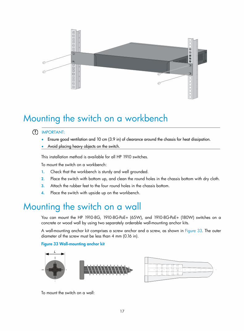
Mounting the switch on a workbench
IMPORTANT:
• Ensure good ventilation and 10 cm (3.9 in) of clearance around the chassis for heat dissipation.
• Avoid placing heavy objects on the switch.
This installation method is available for all HP 1910 switches.
To mount the switch on a workbench:
1. Check that the workbench is sturdy and well grounded.
2. Place the switch with bottom up, and clean the round holes in the chassis bottom with dry cloth.
3. Attach the rubber feet to the four round holes in the chassis bottom.
4. Place the switch with upside up on the workbench.
Mounting the switch on a wall You can mount the HP 1910-8G, 1910-8G-PoE+ (65W), and 1910-8G-PoE+ (180W) switches on a concrete or wood wall by using two separately orderable wall-mounting anchor kits.
A wall-mounting anchor kit comprises a screw anchor and a screw, as shown in Figure 33. The outer diameter of the screw must be less than 4 mm (0.16 in).
Figure 33 Wall-mounting anchor kit
To mount the switch on a wall:

18
1. As shown in Figure 34, drill two holes at the same height and make sure that the spacing in between is as follows:
1910-8G—98.5 mm (3.88 in)
1910-8G-PoE+ (65W)—174.0 mm (6.85 in)
1910-8G-PoE+ (180W)—174.0 mm (6.85 in)
The hole depth and size depends on the anchors and screws you use. Make sure that you can push the anchors to their full depth in the holes, with their outer edges having a close contact with the wall, and tightly fasten the screws to the wall.
Figure 34 Spacing between the mounting holes
2. Insert one anchor into each hole until the anchors are flush with the wall surface. See Figure 35.
3. Drive one screw into each wall anchor, leaving at least 1.5 mm (0.06 in) of clearance between the base of the screw head and the anchor so that the switch can hang on the screws securely.
Figure 35 Install a wall anchor
4. Align the two mounting holes in the switch chassis bottom with the two screws and hang the switch (see Figure 36). Make sure that the Ethernet ports are facing downwards and the chassis side panels are perpendicular to the ground.

19
Figure 36 Wall mounting
(1) Mounting hole in the switch chassis bottom
Grounding the switch
WARNING!
Correctly connecting the switch grounding cable is crucial to lightning protection and EMI protection.
The power input end of the switch has a noise filter, whose central ground is directly connected to the chassis to form the chassis ground (commonly known as PGND). You must securely connect this chassis ground to the earth so the faradism and leakage electricity can be safely released to the earth to minimize EMI susceptibility of the switch.
You can ground the switch in one of the following ways, depending on the grounding conditions available at the installation site:
• Grounding the switch with a grounding strip
• Grounding the switch with a grounding conductor buried in the earth ground
• Grounding the switch by using the AC power cord
NOTE:
The power and grounding terminals in this section are for illustration only.
Grounding the switch with a grounding strip
WARNING!
Connect the grounding cable to the grounding system in the equipment room. Do not connect it to a fire main or lightning rod.
NOTE:
The V1910-24G-PoE (170W) and V1910-24G-PoE (365W) switches come with an OT terminal for connecting to a grounding strip. For other switch models, you must prepare OT terminals yourself.
If a grounding strip is available at the installation site, connect the grounding cable to the grounding strip.
To connect the grounding cable, for example, to a V1910-24G switch:
20
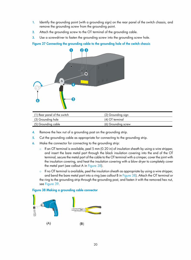
1. Identify the grounding point (with a grounding sign) on the rear panel of the switch chassis, and remove the grounding screw from the grounding point.
2. Attach the grounding screw to the OT terminal of the grounding cable.
3. Use a screwdriver to fasten the grounding screw into the grounding screw hole.
Figure 37 Connecting the grounding cable to the grounding hole of the switch chassis
(1) Rear panel of the switch (2) Grounding sign (3) Grounding hole (4) OT terminal (5) Grounding cable (6) Grounding screw
4. Remove the hex nut of a grounding post on the grounding strip.
5. Cut the grounding cable as appropriate for connecting to the grounding strip.
6. Make the connector for connecting to the grounding strip:
If an OT terminal is available, peel 5 mm (0.20 in) of insulation sheath by using a wire stripper, and insert the bare metal part through the black insulation covering into the end of the OT terminal, secure the metal part of the cable to the OT terminal with a crimper, cover the joint with the insulation covering, and heat the insulation covering with a blow dryer to completely cover the metal part (see callout A in Figure 38).
If no OT terminal is available, peel the insulation sheath as appropriate by using a wire stripper, and bend the bare metal part into a ring (see callout B in Figure 38). Attach the OT terminal or
the ring to the grounding strip through the grounding post, and fasten it with the removed hex nut, see Figure 39.
Figure 38 Making a grounding cable connector

21
Figure 39 Connecting the grounding cable to a grounding strip
(1) Grounding post (2) Grounding strip (3) Grounding cable (4) Hex nut
Grounding the switch with a grounding conductor buried in the earth ground
If the installation site has no grounding strips, but earth ground is available, hammer a 0.5 m (1.64 ft) or longer angle iron or steel tube into the earth ground to serve as a grounding conductor.
The dimensions of the angle iron must be at least 50 × 50 × 5 mm (1.97 × 1.97 × 0.20 in). The steel tube must be zinc-coated and its wall thickness must be at least 3.5 mm (0.14 in).
Weld the yellow-green grounding cable to the angel iron or steel tube and treat the joint for corrosion protection.
Figure 40 Grounding the switch by burying the grounding conductor into the earth ground
(1) Grounding screw (2) Grounding cable (3) Earth (4) Joint (5) Grounding conductor (6) Chassis rear panel
22
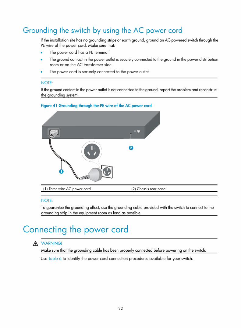
Grounding the switch by using the AC power cord If the installation site has no grounding strips or earth ground, ground an AC-powered switch through the PE wire of the power cord. Make sure that:
• The power cord has a PE terminal.
• The ground contact in the power outlet is securely connected to the ground in the power distribution room or on the AC transformer side.
• The power cord is securely connected to the power outlet.
NOTE:
If the ground contact in the power outlet is not connected to the ground, report the problem and reconstructthe grounding system.
Figure 41 Grounding through the PE wire of the AC power cord
(1) Three-wire AC power cord (2) Chassis rear panel
NOTE:
To guarantee the grounding effect, use the grounding cable provided with the switch to connect to the grounding strip in the equipment room as long as possible.
Connecting the power cord
WARNING!
Make sure that the grounding cable has been properly connected before powering on the switch.
Use Table 6 to identify the power cord connection procedures available for your switch.
23
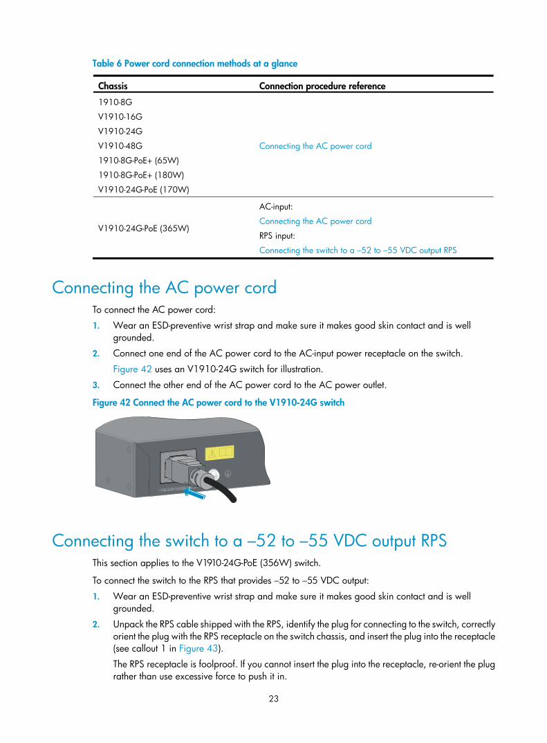
Table 6 Power cord connection methods at a glance
Chassis Connection procedure reference
1910-8G
V1910-16G
V1910-24G
V1910-48G
1910-8G-PoE+ (65W)
1910-8G-PoE+ (180W)
V1910-24G-PoE (170W)
Connecting the AC power cord
V1910-24G-PoE (365W)
AC-input:
Connecting the AC power cord
RPS input:
Connecting the switch to a –52 to –55 VDC output RPS
Connecting the AC power cord To connect the AC power cord:
1. Wear an ESD-preventive wrist strap and make sure it makes good skin contact and is well grounded.
2. Connect one end of the AC power cord to the AC-input power receptacle on the switch.
Figure 42 uses an V1910-24G switch for illustration.
3. Connect the other end of the AC power cord to the AC power outlet.
Figure 42 Connect the AC power cord to the V1910-24G switch
Connecting the switch to a –52 to –55 VDC output RPS This section applies to the V1910-24G-PoE (356W) switch.
To connect the switch to the RPS that provides –52 to –55 VDC output:
1. Wear an ESD-preventive wrist strap and make sure it makes good skin contact and is well grounded.
2. Unpack the RPS cable shipped with the RPS, identify the plug for connecting to the switch, correctly orient the plug with the RPS receptacle on the switch chassis, and insert the plug into the receptacle (see callout 1 in Figure 43).
The RPS receptacle is foolproof. If you cannot insert the plug into the receptacle, re-orient the plug rather than use excessive force to push it in.
24
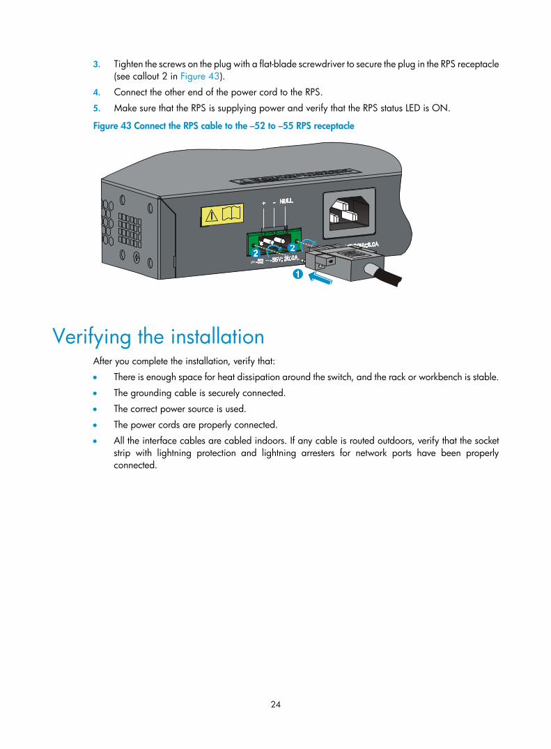
3. Tighten the screws on the plug with a flat-blade screwdriver to secure the plug in the RPS receptacle (see callout 2 in Figure 43).
4. Connect the other end of the power cord to the RPS.
5. Make sure that the RPS is supplying power and verify that the RPS status LED is ON.
Figure 43 Connect the RPS cable to the –52 to –55 RPS receptacle
Verifying the installation After you complete the installation, verify that:
• There is enough space for heat dissipation around the switch, and the rack or workbench is stable.
• The grounding cable is securely connected.
• The correct power source is used.
• The power cords are properly connected.
• All the interface cables are cabled indoors. If any cable is routed outdoors, verify that the socket strip with lightning protection and lightning arresters for network ports have been properly connected.

25
Accessing the switch for the first time
Setting up the configuration environment The first time you access the switch you must use a console cable to connect a console terminal, for example, a PC, to the console port on the switch.
Figure 44 Connect the console port to a terminal
Connecting the console cable
Console cable A console cable is an 8-core shielded cable, with a crimped RJ-45 connector at one end for connecting to the console port of the switch, and a DB-9 female connector at the other end for connecting to the serial port on the console terminal.
Figure 45 Console cable
Connection procedure To connect a terminal, for example, a PC, to the switch:
1. Plug the DB-9 female connector of the console cable to the serial port of the PC.
2. Connect the RJ-45 connector to the console port of the switch.
Main label
1
8 B sideB
Pos.9
Pos.1
A side
A
26
NOTE:
• Identify the mark on the console port and make sure that you are connecting to the correct port.
• The serial ports on PCs do not support hot swapping. If the switch has been powered on, connect the console cable to the PC before connecting to the switch, and when you disconnect the cable, first disconnect from the switch.
Setting terminal parameters To configure and manage the switch, you must run a terminal emulator program on the console terminal.
The following are the required terminal settings:
• Bits per second—38,400
• Data bits—8
• Parity—None
• Stop bits—1
• Flow control—None
• Emulation—VT100
To set terminal parameters, for example, on a Windows XP HyperTerminal:
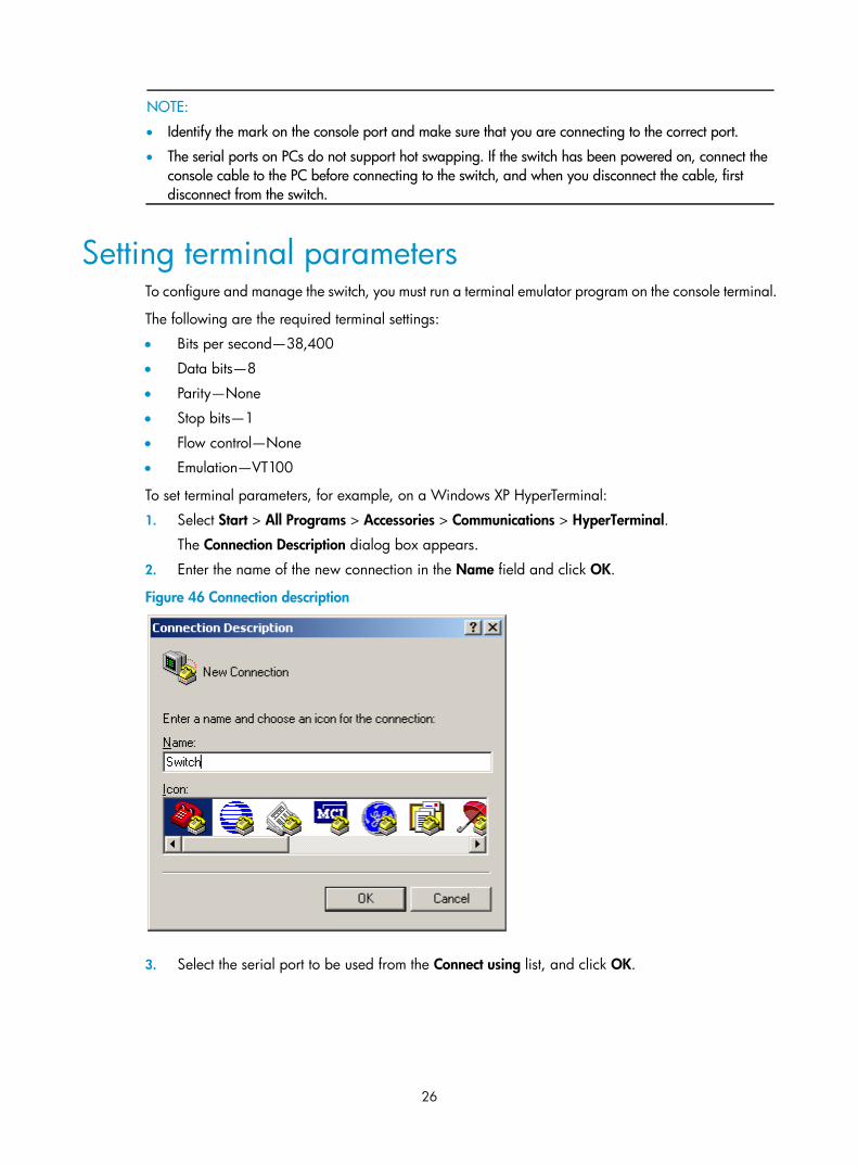
1. Select Start > All Programs > Accessories > Communications > HyperTerminal.
The Connection Description dialog box appears.
2. Enter the name of the new connection in the Name field and click OK.
Figure 46 Connection description
3. Select the serial port to be used from the Connect using list, and click OK.

27
Figure 47 Set the serial port used by the HyperTerminal connection
4. Set Bits per second to 38400, Data bits to 8, Parity to None, Stop bits to 1, and Flow control to None, and click OK.
Figure 48 Set the serial port parameters
5. Select File > Properties in the HyperTerminal window.

28
Figure 49 HyperTerminal window
6. On the Settings tab, set the emulation to VT100 and click OK.
Figure 50 Set terminal emulation in Switch Properties dialog box

29
Powering on the switch
Verification before power-on Before powering on the switch, verify that:
• The power cord is properly connected.
• The input power voltage meets the requirement of the switch.
• The console cable is properly connected, the terminal or PC used for configuration has started, and the configuration parameters have been correctly set.
Powering on the switch Power on the switch, for example, an HP V1910-24G switch, and you can see the following information: Starting......
************************************************************************
* *
* HP V1910-24G Switch JE006A BOOTROM, Version 135 *
* *
************************************************************************
Copyright (c) 2010-2011 Hewlett-Packard Development Company, L.P.
Creation Date : Jan 9 2011
CPU Type : ARM926
CPU L1 Cache : 32KB
CPU Clock Speed : 333MHz
Memory Type : DDR2 SDRAM
Memory Size : 128MB
Flash Size : 128MB
CPLD Version : 001
PCB Version : Ver.B
Mac Address : 000ef2001910
Press Ctrl-B to enter Extended Boot menu...1
Press Ctrl + B at the prompt within one second to access the Boot menu, or wait for the system to automatically start up.
NOTE:
The system has two startup modes: full startup and fast startup. By default, the system starts up in fast modeand the waiting time is one second. In full startup mode, the waiting time is five seconds. To change the startup mode, see “Changing the startup mode.”
• If you press Ctrl + B within one second, the system displays a prompt for password: Password:
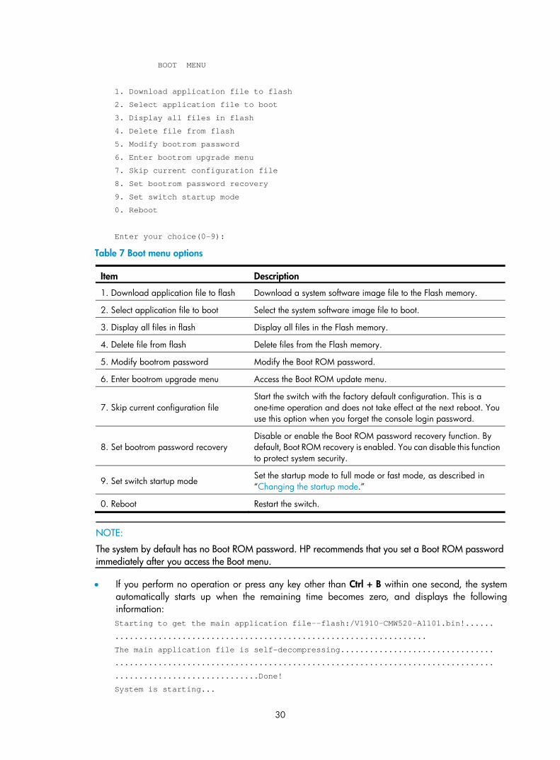
Press Enter at the prompt the first time you access the switch and you can see the following Boot menu:
30
BOOT MENU
1. Download application file to flash
2. Select application file to boot
3. Display all files in flash
4. Delete file from flash
5. Modify bootrom password
6. Enter bootrom upgrade menu
7. Skip current configuration file
8. Set bootrom password recovery
9. Set switch startup mode
0. Reboot
Enter your choice(0-9):
Table 7 Boot menu options
Item Description
1. Download application file to flash Download a system software image file to the Flash memory.
2. Select application file to boot Select the system software image file to boot.
3. Display all files in flash Display all files in the Flash memory.
4. Delete file from flash Delete files from the Flash memory.
5. Modify bootrom password Modify the Boot ROM password.
6. Enter bootrom upgrade menu Access the Boot ROM update menu.
7. Skip current configuration file Start the switch with the factory default configuration. This is a one-time operation and does not take effect at the next reboot. You use this option when you forget the console login password.
8. Set bootrom password recovery Disable or enable the Boot ROM password recovery function. By default, Boot ROM recovery is enabled. You can disable this function to protect system security.
9. Set switch startup mode Set the startup mode to full mode or fast mode, as described in “Changing the startup mode.”
0. Reboot Restart the switch.
NOTE:
The system by default has no Boot ROM password. HP recommends that you set a Boot ROM password immediately after you access the Boot menu.
• If you perform no operation or press any key other than Ctrl + B within one second, the system automatically starts up when the remaining time becomes zero, and displays the following information: Starting to get the main application file--flash:/V1910-CMW520-A1101.bin!......
.................................................................
The main application file is self-decompressing................................
...............................................................................
..............................Done!
System is starting...

31
User interface aux0 is available.
Press ENTER to get started.
Press Enter at the prompt, and you can configure the switch when the prompt <HP> appears.
Changing the startup mode The system by default starts up in fast mode. To change to the full startup mode, press Ctrl + B within one second to access the Boot menu: BOOT MENU
1. Download application file to flash
2. Select application file to boot
3. Display all files in flash
4. Delete file from flash
5. Modify bootrom password
6. Enter bootrom upgrade menu
7. Skip current configuration file
8. Set bootrom password recovery
9. Set switch startup mode
0. Reboot
Enter your choice(0-9):
Enter 9 to change the startup mode. The current mode is fast startup mode!
Are you sure you want to change it to full startup mode? Yes or No(Y/N)
Enter Y at the prompt. Setting startup mode...done!
BOOT MENU
1. Download application file to flash
2. Select application file to boot
3. Display all files in flash
4. Delete file from flash
5. Modify bootrom password
6. Enter bootrom upgrade menu
7. Skip current configuration file
8. Set bootrom password recovery
9. Set switch startup mode
0. Reboot
Enter your choice(0-9):
Enter 0 at the prompt. The system reboots in full startup mode and displays the following information: Starting......
************************************************************************
32
* *
* HP V1910-24G Switch JE006A BOOTROM, Version 135 *
* *
************************************************************************
Copyright (c) 2010-2011 Hewlett-Packard Development Company, L.P.
Creation Date : Jan 9 2011
CPU Type : ARM926
CPU L1 Cache : 32KB
CPU Clock Speed : 333MHz
Memory Type : DDR2 SDRAM
Memory Size : 128MB
Flash Size : 128MB
CPLD Version : 001
PCB Version : Ver.B
Mac Address : 000ef2001910
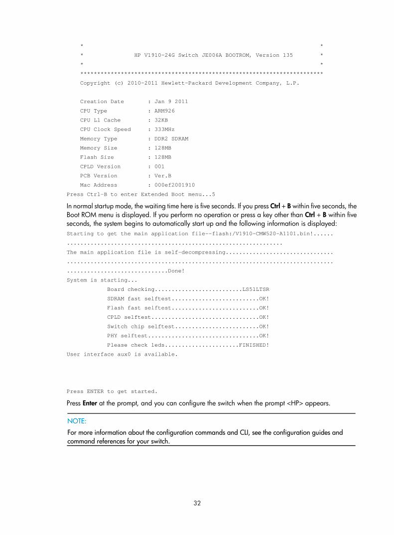
Press Ctrl-B to enter Extended Boot menu...5
In normal startup mode, the waiting time here is five seconds. If you press Ctrl + B within five seconds, the Boot ROM menu is displayed. If you perform no operation or press a key other than Ctrl + B within five seconds, the system begins to automatically start up and the following information is displayed: Starting to get the main application file--flash:/V1910-CMW520-A1101.bin!......
................................................................
The main application file is self-decompressing................................
...............................................................................
..............................Done!
System is starting...
Board checking..........................LS51LTSR
SDRAM fast selftest..........................OK!
Flash fast selftest..........................OK!
CPLD selftest................................OK!
Switch chip selftest.........................OK!
PHY selftest.................................OK!
Please check leds......................FINISHED!
User interface aux0 is available.
Press ENTER to get started.
Press Enter at the prompt, and you can configure the switch when the prompt <HP> appears.
NOTE:
For more information about the configuration commands and CLI, see the configuration guides and command references for your switch.

33
Maintenance and troubleshooting
Password loss
Console login password loss If you forget the console login password, access the Boot menu: BOOT MENU
1. Download application file to flash
2. Select application file to boot
3. Display all files in flash
4. Delete file from flash
5. Modify bootrom password
6. Enter bootrom upgrade menu
7. Skip current configuration file
8. Set bootrom password recovery
9. Set switch startup mode
0. Reboot
Enter your choice(0-9):
Enter 7 and restart the switch. The switch reboots with empty configuration, and you can log in through the console port without entering the password to check the configuration file for the user password.
Boot ROM password loss Contact the HP technical support for help.
Power supply failure The V1910-24G-PoE (365W) adopts AC power input, RPS power input, or both RPS and AC power inputs. Other 1910 switches adopt AC power input only.
You can look at the power LED and the RPS status LED on the front panel of the switch to identify a power system failure.
AC input
If the switch is AC powered, look at the system status LED to identify a power failure. If the system status LED is off, an AC input failure has occurred. Check the following items:
• The AC power cord is well connected to the switch, and the AC receptacle on the switch and the AC power receptacle are normal.
• The external AC power supply system is correctly working.
• The operating temperature of the switch is normal, and the power module has good ventilation (over-temperature can cause a power module to stop working and enter the protection state).

34
RPS input
If the switch is RPS powered, look at the system status LED or RPS status LED to identify a power failure. If the system status LED or RPS status LED is off, an RPS input failure has occurred. Check the following items:
• The switch is well connected to the external RPS power supply.
• The external RPS is correctly working.
• The operating temperature of the switch is normal, and the power module has good ventilation (over-temperature can cause the power module to stop working and enter the protection state).
Concurrent AC and RPS inputs
If the switch is concurrently powered by an RPS and an AC power supply, look at the power LED and RPS status LED to identify an RPS or AC input failure.
1. If the power LED is off, the AC power supply and the RPS both have an input failure.
Check the following items:
• The AC power cord is well connected to the switch, and the AC receptacle on the switch and the connected AC power receptacle are normal.
• The AC external power supply system is normal.
• The switch is well connected to the external RPS.
• The external RPS is correctly working.
• The operating temperature of the switch is normal, and the power module has good ventilation (over-temperature can cause the power module to stop working and enter the protection state).
2. If the power LED is on but the RPS status LED is off, an RPS input failure has occurred.
Check the following items:
• The switch is well connected to the external RPS power supply.
• The external RPS is correctly working.
NOTE:
If the problem persists, contact the HP technical support for help.
Configuration terminal problems If the configuration environment setup is correct, the configuration terminal displays booting information when the switch is powered on. If the setup is incorrect, the configuration terminal would display nothing or garbled text.
No terminal display
If the configuration terminal displays nothing after the switch is powered on, verify the following items:
• The power supply is supplying power to the switch.
• The console cable is properly connected.
• The console cable has no problem and the terminal settings are correct.
Garbled terminal display
If terminal display is garbled, verify that the following settings are configured for the terminal, for example, HyperTerminal:

35
• Baud rate—38,400
• Data bits—8
• Parity—none
• Stop bits—1
• Flow control—none
• Emulation—VT100

36
Support and other resources
Contacting HP For worldwide technical support information, see the HP support website:
http://www.hp.com/support
Before contacting HP, collect the following information:
• Product model names and numbers
• Technical support registration number (if applicable)
• Product serial numbers
• Error messages
• Operating system type and revision level
• Detailed questions
Subscription service HP recommends that you register your product at the Subscriber's Choice for Business website:
http://www.hp.com/go/wwalerts
After registering, you will receive email notification of product enhancements, new driver versions, firmware updates, and other product resources.
Related information
Documents To find related documents, browse to the Manuals page of the HP Business Support Center website:
http://www.hp.com/support/manuals
• For related documentation, navigate to the Networking section, and select a networking category.
• For a complete list of acronyms and their definitions, see HP A-Series Acronyms.
Websites • HP.com http://www.hp.com
• HP Networking http://www.hp.com/go/networking
• HP manuals http://www.hp.com/support/manuals
• HP download drivers and software http://www.hp.com/support/downloads
• HP software depot http://www.software.hp.com
• HP Education http://www.hp.com/learn

37
Conventions This section describes the conventions used in this documentation set.
Command conventions
Convention Description
Boldface Bold text represents commands and keywords that you enter literally as shown.
Italic Italic text represents arguments that you replace with actual values.
[ ] Square brackets enclose syntax choices (keywords or arguments) that are optional.
{ x | y | ... } Braces enclose a set of required syntax choices separated by vertical bars, from which you select one.
[ x | y | ... ] Square brackets enclose a set of optional syntax choices separated by vertical bars, from which you select one or none.
{ x | y | ... } * Asterisk-marked braces enclose a set of required syntax choices separated by vertical bars, from which you select at least one.
[ x | y | ... ] * Asterisk-marked square brackets enclose optional syntax choices separated by vertical bars, from which you select one choice, multiple choices, or none.
&<1-n> The argument or keyword and argument combination before the ampersand (&) sign can be entered 1 to n times.
# A line that starts with a pound (#) sign is comments.
GUI conventions
Convention Description
Boldface Window names, button names, field names, and menu items are in bold text. For example, the New User window appears; click OK.
> Multi-level menus are separated by angle brackets. For example, File > Create > Folder.
Symbols
Convention Description
WARNING An alert that calls attention to important information that if not understood or followed can result in personal injury.
CAUTION An alert that calls attention to important information that if not understood or followed can result in data loss, data corruption, or damage to hardware or software.
IMPORTANT An alert that calls attention to essential information.
NOTE An alert that contains additional or supplementary information.
TIP An alert that provides helpful information.

38
Network topology icons
Represents a generic network device, such as a router, switch, or firewall.
Represents a routing-capable device, such as a router or Layer 3 switch.
Represents a generic switch, such as a Layer 2 or Layer 3 switch, or a router that supports Layer 2 forwarding and other Layer 2 features.
Port numbering in examples
The port numbers in this document are for illustration only and might be unavailable on your device.

39
Appendix A Technical specifications
Physical specifications
Chassis dimensions and weights
Chassis Dimensions (H × W × D) Weight
1910-8G 43.6 × 210 × 210 mm (1.72 × 8.27 × 8.27 in) ≤ 2 kg (4.41 lb)
V1910-16G
V1910-24G 43.6 × 440 × 160 mm (1.72 × 17.32 × 6.30 in)
≤ 3 kg (6.61 lb)
1910-8G-PoE+ (65W)
1910-8G-PoE+ (180W) 43.6 × 300 × 260 mm (1.72 × 11.81 × 10.24 in) ≤ 3 kg (6.61 lb)
V1910-24G-PoE (170W)
V1910-24G-PoE (365W) 43.6 × 440 × 420 mm (1.72 × 17.32 × 16.54 in) ≤ 7 kg (15.43 lb)
V1910-48G 43.6 × 440 × 260 mm (1.72 × 17.32 × 10.24 in) ≤ 5 kg (11.02 lb)
Ports and interface card slots
Chassis Console ports
10/100/1000Base-T auto-sensing Ethernet ports
1000Base-X SFP ports
Interafce card slots
1910-8G 1 8 1 N/A
V1910-16G 1 16 4 N/A
V1910-24G 1 24 4 N/A
1910-8G-PoE+ (180W) 1 8, PoE+ 1 N/A
1910-8G-PoE+ (65W) 1 8, PoE+ 1 N/A
V1910-24G-PoE (365W) 1 24, PoE+ 4 N/A
V1910-24G-PoE (170W) 1 24, PoE+ 4 N/A
V1910-48G 1 48 4 N/A
Environmental specifications
Chassis Operating temperature Relative humidity
All chassis 0°C to 45°C (32°F to 113°F) 10% to 90%, noncondensing

40
Power specifications
Power input types
Chassis AC-input power receptacle RPS receptacle
All 1910 chassis but the V1910-24G-PoE (365W)
1 N/A
V1910-24G-PoE (365W) 1 1
The RPS can supply power to your switch when the AC power line fails or cannot supply sufficient power.
AC input voltage specifications
Chassis Rated voltage range Max voltage range
All chassis 100 VAC to 240 VAC, 50 Hz or 60 Hz 90 VAC to 264 VAC, 47 Hz to 63 Hz
RPS DC input voltage specifications and RPS compatibility
Chassis RPS input rated voltage range Compatible RPS
V1910-24G-PoE (365W) –52 VDC to –55 VDC A-RPS1600 (JG136A)
Power consumption specifications for non-PoE switches
Chassis Minimum power consumption Maximum power consumption
1910-8G 8.7 W 14.4 W
V1910-16G 11.9 W 25.1 W
V1910-24G 13.4 W 31.5 W
V1910-48G 25.7 W 59.8 W
Power consumption specifications for PoE switches
Chassis Maximum PoE power per port
Maximum PoE ports at full 30 W output
Total PoE output
Minimum power consumption
Maximum power consumption (including total PoE output)
1910-8G-PoE+ (180W) 30 W 6 180 W 19 W 230 W

41
Chassis Maximum PoE power per port
Maximum PoE ports at full 30 W output
Total PoE output
Minimum power consumption
Maximum power consumption (including total PoE output)
1910-8G-PoE+ (65W) 30 W 2 65 W 10 W 95 W
V1910-24G-PoE (365W) 30 W
12 at AC input
24 at RPS DC input
370 W at AC input
740 W at RPS DC input
45.6 W at AC input
27.5 W at RPS DC input
528 W at AC input
832 W at RPS DC input
V1910-24G-PoE (170W)
30 W 5 170 W 25.0 W 255 W
Cooling system
Chassis Fixed fans
1910-8G
1910-8G-PoE+ (65W) N/A
V1910-16G
V1910-24G
V1910-48G
1
1910-8G-PoE+ (180W)
V1910-24G-PoE (170W) 3
V1910-24G-PoE (365W) 6

42
Appendix B FRUs and compatibility matrixes
This appendix describes the FRUs available for the HP 1910 switches and their compatibility.
SFP transceiver modules and SFP Stacking Kit
NOTE:
• To guarantee the functionality of the SFP ports, use only HP SFP transceiver modules.
• The SFP transceiver modules available for this switch series are subject to change over time. For the mostup-to-date list of SFP transceiver modules, consult your HP sales representative or technical support engineer.
• For the SFP transceiver module specifications, see HP A-Series Switches Transceiver Modules User Guide.
Product code Module description
Central wavelength (nm)
Cable/fiber diameter (μm)
Multimode fiber modal bandwidth (MHz × km)
Maximum transmission distance
JD118B HP X120 1G SFP LC SX Transceiver 850
50/125
500 550 m (1804.46 ft)
400 500 m (1640.42 ft)
62.5/125
200 275 m (902.23 ft)
160 220 m (721.78 ft)
JD119B HP X120 1G SFP LC LX Transceiver
1310
9/125 N/A 10 km (6.21 miles)
50/125 500, 400 550 m (1804.46 ft)
62.5/125 500 550 m (1804.46 ft)
JD061A HP X125 1G SFP LC LH40 1310nm Transceiver 1310 9/125 N/A
40 km (24.86 miles)
JD062A HP X120 1G SFP LC LH40 1550nm Transceiver 1550 9/125 N/A
40 km (24.86 miles)
JD063B HP X125 1G SFP LC LH70 Transceiver 1550 9/125 N/A
70 km (43.50 miles)
JD098B HP X120 1G SFP LC BX 10-U Transceiver
TX: 1310nm
RX: 1490nm 9/125 N/A
10 km (6.21 miles)
JD099B HP X120 1G SFP LC BX 10-D Transceiver
TX: 1490nm
RX: 1310nm 9/125 N/A
10 km (6.21 miles)
43
Product code Module description
Central wavelength (nm)
Cable/fiber diameter (μm)
Multimode fiber modal bandwidth (MHz × km)
Maximum transmission distance
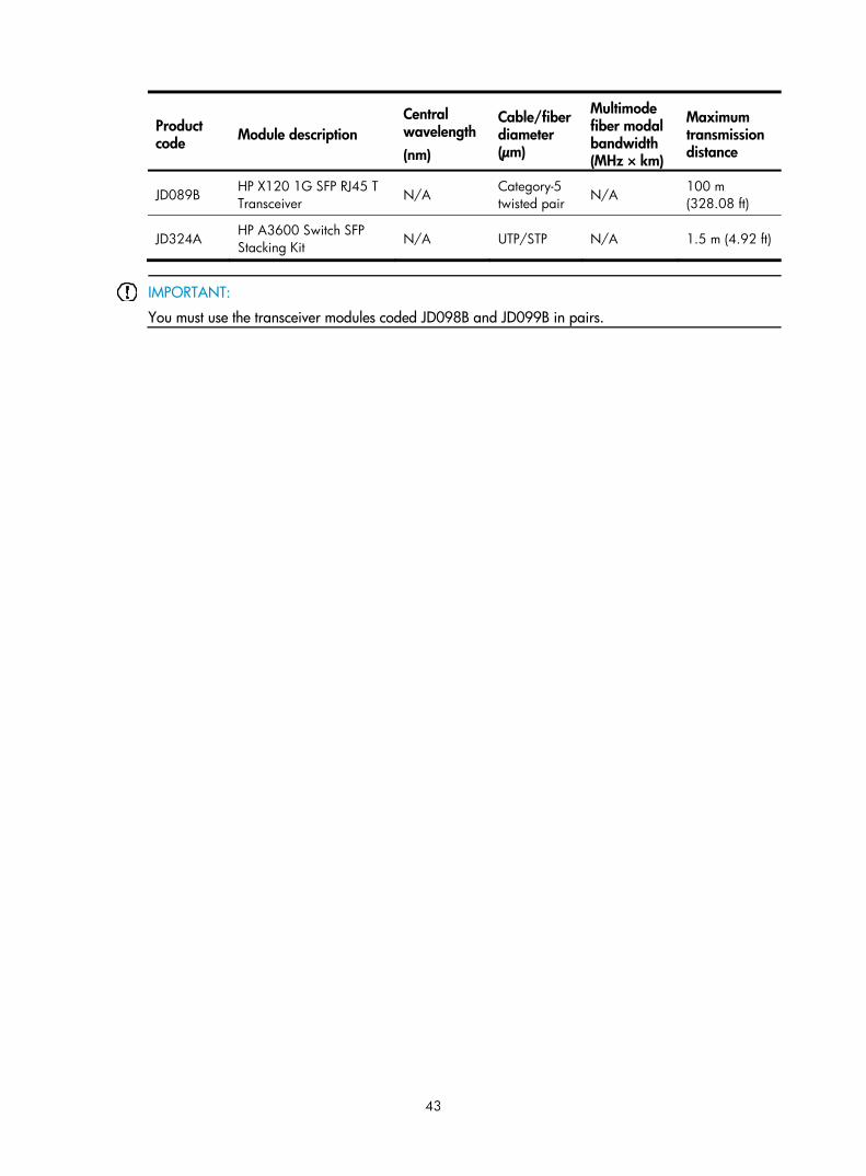
JD089B HP X120 1G SFP RJ45 T Transceiver N/A
Category-5 twisted pair N/A
100 m (328.08 ft)
JD324A HP A3600 Switch SFP Stacking Kit N/A UTP/STP N/A 1.5 m (4.92 ft)
IMPORTANT:
You must use the transceiver modules coded JD098B and JD099B in pairs.

44
Appendix C Ports and LEDs
Ports
Console port Every HP 1910 switch provides one console port on the front panel.
Table 8 Console port specifications
Item Specification
Connector type RJ-45
Compliant standard EIA/TIA-232
Transmission baud rate 9600 bps (default) to 115200 bps
Service
• Provides connection to an ASCII terminal. • Provides connection to the serial port of a local or remote
(through a pair of modems) PC running terminal emulation program.
10/100/1000Base-T Ethernet port Table 9 10/100/1000Base-T Ethernet port specifications
Item Specification
Connector type RJ-45
Interface standard
• 10 Mbps, half/full duplex • 100 Mbps, half/full duplex • 1000 Mbps, full duplex • MDI/MDI-X, auto-sensing
Max transmission distance 100 m (328.08 ft)
Transmission medium Category-5 (or above) twisted pair cable
Standards IEEE 802.3i, 802.3u, 802.3ab
SFP port All HP 1910 switches have 1000Base-X SFP ports. For the SFP transceiver modules available for the HP 1910 switches, see “SFP transceiver modules and SFP Stacking Kit.”

45
LEDs Table 10 LEDs at a glance
LED Availability
Power LED Entire series
RPS status LED V1910-24G-PoE (365W)
Port mode LED 1910-8G-PoE+ (65W) , 1910-8G-PoE+ (180W), V1910-24G-PoE (170W), V1910-24G-PoE (365W)
10/100/1000Base-T Ethernet port LED Entire series
1000Base-X SFP port LED Entire series
Power LED The power LED shows the operation status of the switch.
Table 11 Power LED description
LED mark Status Description
Power
Steady green The switch is operating properly.
Flashing green (1 Hz) The system is performing power-on self test (POST) or downloading software.
Flashing green (3 Hz) POST has failed or another fatal error has been detected.
Off The switch has been powered off.
RPS status LED The V1910-24G-PoE (365W) has one RPS status LED on its front panel to show the operating status of the RPS DC input.
Table 12 RPS status LED description
LED mark Status Description
RPS Steady green The RPS DC input is normal.
Off The RPS unit is not connected or the RPS DC input is abnormal.
Port mode LED The 1910-8G-PoE+ (65W), 1910-8G-PoE+ (180W), V1910-24G-PoE (170W), and V1910-24G-PoE (365W) switches have a port mode LED to indicate the type of information that the network port LEDs (excluding the SFP port LEDs) are showing. You can use the port LED mode switching button to change the type of displayed port information.

46
Table 13 Port mode LED description
LED mark Status Description
Mode
Steady green The network port LEDs are showing port rates.
Flashing green (1 Hz) The network port LEDs are showing the status of PoE power supply on the ports.
10/100/1000Base-T Ethernet port LED The V1910-48G switch has one bi-color LED (see Table 14) for each 10/100/1000Base-T Ethernet port, and all other HP 1910 switches have two LEDs (see Table 15) for each 10/100/1000Base-T Ethernet port. The 1910-8G-PoE+ (65W), 1910-8G-PoE+ (180W), V1910-24G-PoE (170W), and V1910-24G-PoE (365W) switches also use a port mode LED to indicate the type of information that the port LEDs are displaying (see Table 16).
Table 14 Ethernet port LED description (V1910-48G)
Status Description
Steady green The port is operating at 1000 Mbps.
Fast flashing green The port is sending or receiving data at 1000 Mbps.
Steady yellow The port is operating at 10/100 Mbps.
Fast flashing yellow The port is sending or receiving data at 10/100 Mbps.
Off No link is present on the port.
Table 15 Ethernet port LED description (1910-8G/V1910-16G/V1910-24G)
LED Status Description
Green
On The port is operating at 1000 Mbps.
Fast flashing The port is sending or receiving data at 1000 Mbps.
Off The port has no link or is not operating at 1000 Mbps.
Yellow
On The port is operating at 10/100 Mbps.
Fast flashing The port is sending or receiving data at 10/100 Mbps.
Off The port has no link or is not operating at 10/100 Mbps.
Table 16 Ethernet port LED description (all other 1910 switches)
Port mode LED (Mode) status Port LED Port LED status Description
Steady green (rate mode)
Green
On The port is operating at 1000 Mbps.
Fast flashing The port is sending or receiving data at 1000 Mbps.

47
Port mode LED (Mode) status Port LED Port LED status Description
Off The port has no link or is not operating at 1000 Mbps.
Yellow
On The port is operating at 10/100 Mbps.
Fast flashing The port is sending or receiving data at 10/100 Mbps.
Off No link is present on the port.
Flashing green (PoE mode)
Green
On PoE power supply is normal.
Flashing at 3 Hz The device attached to the port requires power higher than the maximum or currently available PoE output power on the port.
Off The port is not supplying power.
Yellow
On The device attached to the port is not a powered device or a PoE failure has occurred.
Off The port is supplying power normally or not supplying power.
1000Base-X SFP port LED Table 17 1000Base-X SFP port LEDs description
Status Description
Steady green The port is operating at 1000 Mbps.
Flashing green The port is sending or receiving data.
Off No link is present on the port.

48
Index
C E G I L M P R S V C
Configuration terminal problems,34 Connecting the console cable,25 Connecting the power cord,22 Contacting HP,36 Conventions,37 Cooling system,41
E
Environmental specifications,39 Examining the installation site,7
G
Grounding the switch,19
I
Installation tools,9 Installing the switch in a 19-inch rack,10
L
LEDs,45
M
Mounting the switch on a wall,17 Mounting the switch on a workbench,17
P
Password loss,33 Physical specifications,39 Ports,44 Power specifications,40 Power supply failure,33 Powering on the switch,29
R
Related information,36
S
Safety recommendations,7 Setting terminal parameters,26 Setting up the configuration environment,25 SFP transceiver modules and SFP Stacking Kit,42
V
V1910-16G panel views,2 V1910-24G panel views,2 V1910-24G-PoE (170W) panel views,3 V1910-24G-PoE (365W) panel views,4 V1910-48G panel views,3 Verifying the installation,24