how to implement 2c serial communication using intel mcs ...electro8051.free.fr/i2c/27231901.pdf ·...
TRANSCRIPT
APPLICATIONNOTE
AP-476
April 1993
How to ImplementI2C Serial CommunicationUsing Intel MCS-51Microcontrollers
SABRINA D. QUARLES
APPLICATIONS ENGINEER
Order Number: 272319-001
Information in this document is provided in connection with Intel products. Intel assumes no liability whatsoev-er, including infringement of any patent or copyright, for sale and use of Intel products except as provided inIntel’s Terms and Conditions of Sale for such products.
Intel retains the right to make changes to these specifications at any time, without notice. MicrocomputerProducts may have minor variations to this specification known as errata.
*Other brands and names are the property of their respective owners.
²Since publication of documents referenced in this document, registration of the Pentium, OverDrive andiCOMP trademarks has been issued to Intel Corporation.
Contact your local Intel sales office or your distributor to obtain the latest specifications before placing yourproduct order.
Copies of documents which have an ordering number and are referenced in this document, or other Intelliterature, may be obtained from:
Intel CorporationP.O. Box 7641Mt. Prospect, IL 60056-7641
or call 1-800-879-4683
COPYRIGHT © INTEL CORPORATION, 1996
How to Implement I2C Serial CommunicationUsing Intel MCS-51 Microcontrollers
CONTENTS PAGE
INTRODUCTION ÀÀÀÀÀÀÀÀÀÀÀÀÀÀÀÀÀÀÀÀÀÀÀÀÀÀÀ 1
I2C-Bus System ÀÀÀÀÀÀÀÀÀÀÀÀÀÀÀÀÀÀÀÀÀÀÀÀÀÀÀÀ 1
I2C Hardware Characteristics ÀÀÀÀÀÀÀÀÀÀÀÀÀÀÀ 1
I2C Protocol Characteristics ÀÀÀÀÀÀÀÀÀÀÀÀÀÀÀÀ 2
MCS-51 Hardware Requirements ÀÀÀÀÀÀÀÀÀÀÀ 4
MCS-51 I2C Software EmulationModules ÀÀÀÀÀÀÀÀÀÀÀÀÀÀÀÀÀÀÀÀÀÀÀÀÀÀÀÀÀÀÀÀÀ 5
CONTENTS PAGE
MCS-51 and I2C-Bus Compatible IC’sSystem Implementation ÀÀÀÀÀÀÀÀÀÀÀÀÀÀÀÀÀÀ 6
I2C Software Emulation Performance ÀÀÀÀÀÀÀ 7
CONCLUSION ÀÀÀÀÀÀÀÀÀÀÀÀÀÀÀÀÀÀÀÀÀÀÀÀÀÀÀÀÀ 7
REFERENCES ÀÀÀÀÀÀÀÀÀÀÀÀÀÀÀÀÀÀÀÀÀÀÀÀÀÀÀÀÀ 7

AP-476
INTRODUCTION
Did you know that you could implement I2C function-ality using the Intel MCS-51 family of microcontrol-lers? The I2C-bus allows the designer to implement in-telligent application-oriented control circuits withoutencountering numerous interfacing problems. This bussimplicity is maintained by being structured for eco-nomical, efficient and versatile serial communication.Proven I2C applications are currently being implement-ed in digital control/signal processing circuits for audioand video systems, DTMF generators for telephoneswith tone dialing and ACCESS.bus, a lower-cost alter-native for the RS-232C interface used for connectingperipherals to a host computer.
This application note describes a software emulationimplementation of the I2C-bus Master-Slave configura-tion using Intel MCS-51 microcontrollers. It is recom-mended that the reader become familiar with the Phil-lips Semiconductors I2C-bus Specification and the IntelMCS-51 Architecture. However, it is possible to gain abasic understanding of the I2C-bus and the I2C emula-tion software from this application note.
I2C-Bus System
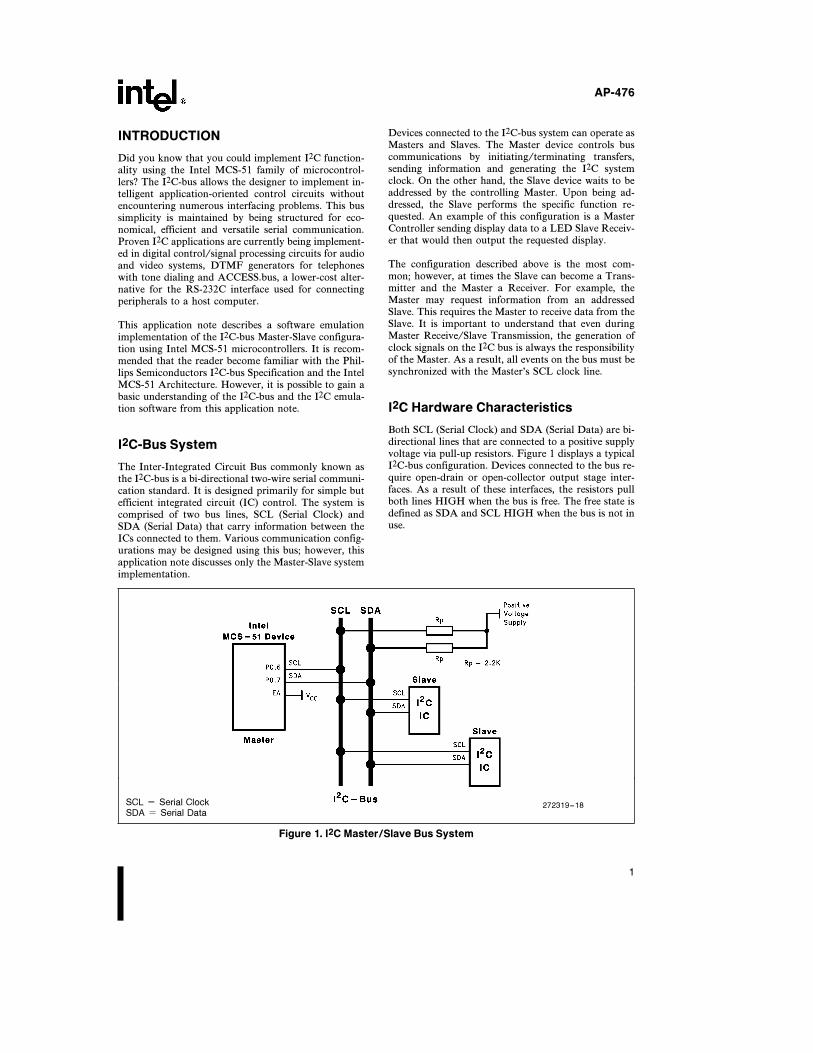
The Inter-Integrated Circuit Bus commonly known asthe I2C-bus is a bi-directional two-wire serial communi-cation standard. It is designed primarily for simple butefficient integrated circuit (IC) control. The system iscomprised of two bus lines, SCL (Serial Clock) andSDA (Serial Data) that carry information between theICs connected to them. Various communication config-urations may be designed using this bus; however, thisapplication note discusses only the Master-Slave systemimplementation.
Devices connected to the I2C-bus system can operate asMasters and Slaves. The Master device controls buscommunications by initiating/terminating transfers,sending information and generating the I2C systemclock. On the other hand, the Slave device waits to beaddressed by the controlling Master. Upon being ad-dressed, the Slave performs the specific function re-quested. An example of this configuration is a MasterController sending display data to a LED Slave Receiv-er that would then output the requested display.
The configuration described above is the most com-mon; however, at times the Slave can become a Trans-mitter and the Master a Receiver. For example, theMaster may request information from an addressedSlave. This requires the Master to receive data from theSlave. It is important to understand that even duringMaster Receive/Slave Transmission, the generation ofclock signals on the I2C bus is always the responsibilityof the Master. As a result, all events on the bus must besynchronized with the Master’s SCL clock line.
I2C Hardware Characteristics
Both SCL (Serial Clock) and SDA (Serial Data) are bi-directional lines that are connected to a positive supplyvoltage via pull-up resistors. Figure 1 displays a typicalI2C-bus configuration. Devices connected to the bus re-quire open-drain or open-collector output stage inter-faces. As a result of these interfaces, the resistors pullboth lines HIGH when the bus is free. The free state isdefined as SDA and SCL HIGH when the bus is not inuse.
SCL e Serial Clock 272319–18SDA e Serial Data
Figure 1. I2C Master/Slave Bus System
1
AP-476
One important bus characteristic enabled as a result ofthis hardware configuration is the wired-AND func-tion. Similar to the logic AND truth table, when drivenby connected ICs, I2C-bus lines will not indicate theHIGH state until all devices verify that they too haveachieved the same HIGH state. An I2C-bus system re-lies on wired-AND functionality to maintain appropri-ate clock synchronization and to communicate effec-tively with extremely high and low speed devices. As aresult, a relatively slow I2C device can extend the sys-tem clock until it is ready to accept more data.
I2C Protocol Characteristics
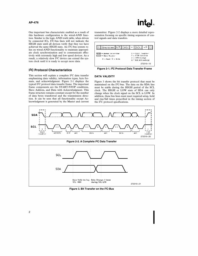
This section will explain a complete I2C data transferemphasizing data validity, information types, byte for-mats, and acknowledgment. Figure 2-1 displays thetypical I2C protocol data transfer frame. The importantframe components are the START/STOP conditions,Slave Address, and Data with Acknowledgment. Thisframe structure remains constant except for the numberof data bytes transferred and the transmission direc-tion. It can be seen that all functionality except Ac-knowledgment is generated by the Master and current
transmitter. Figure 2-2 displays a more detailed repre-sentation focusing on specific timing sequences of con-trol signals and data transfers.
272319–19
Figure 2-1. I2C Protocol Data Transfer Frame
DATA VALIDITY
Figure 3 shows the bit transfer protocol that must bemaintained on the I2C-bus. The data on the SDA linemust be stable during the HIGH period of the SCLclock. The HIGH or LOW state of SDA can onlychange when the clock signal on the SCL is LOW. Inaddition, these bus lines must meet required setup, holdand rise/fall times prescribed in the timing section ofthe I2C protocol specifications.
272319–20
Figure 2-2. A Complete I2C Data Transfer
272319–21
Figure 3. Bit Transfer on the I2C-Bus
2
AP-476
Control Signals
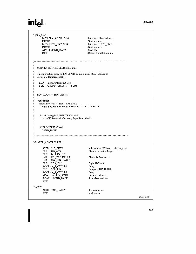
START and STOP conditions are used to signal thebeginning and end of data communications. A Mastergenerates a START condition (S) to obtain control of afree I2C-bus by forcing a HIGH to LOW transition onthe SDA line while maintaining SCL in its HIGH state.This condition is generated during software emulationin the MASTERÐCONTROLLER subroutine de-scribed in another section. Again, START conditionsmay be generated by a Master only when the I2C-bus isfree. This free bus state exists only when no other Mas-ter devices have control of the bus (i.e. both SCL andSDA lines are pulled to their normal HIGH state).
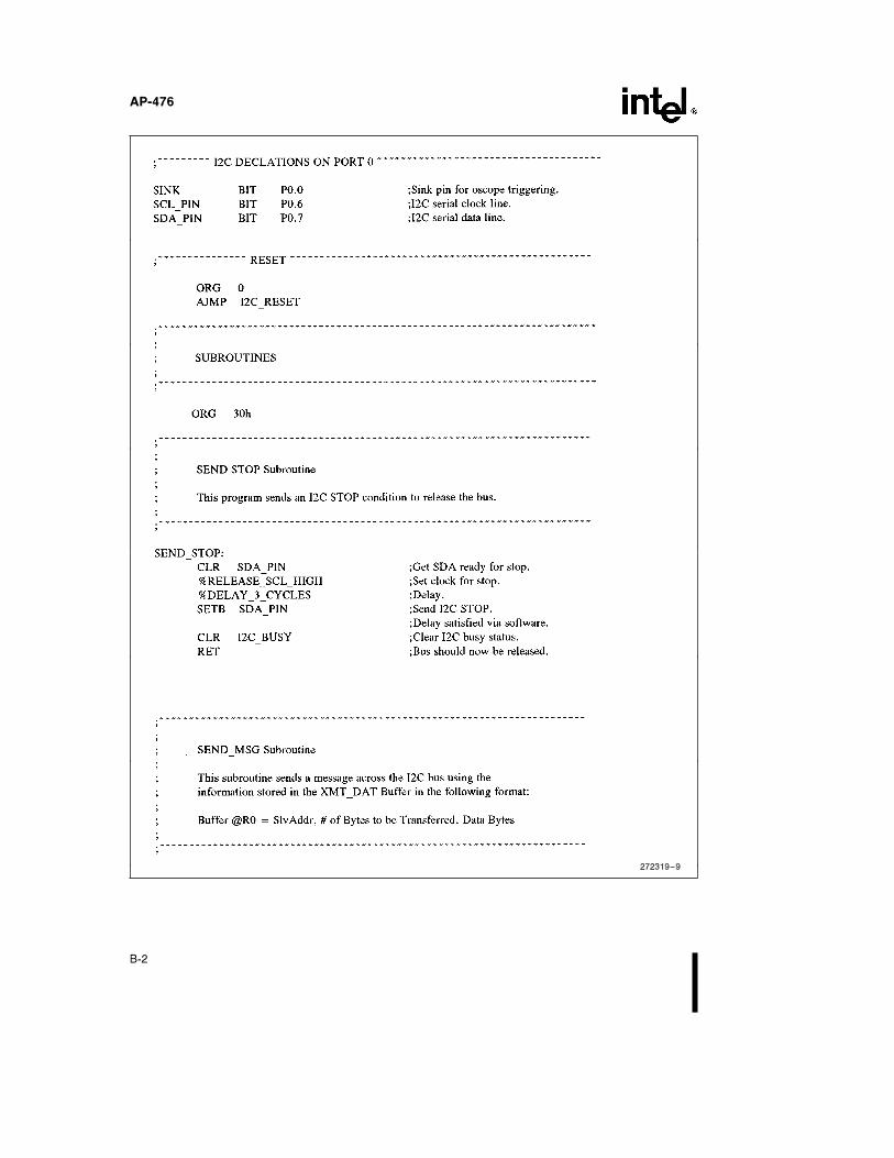
Upon gaining control of the bus, the Master musttransfer data across the system. After a complete datatransfer, the Master must release the bus by generatinga STOP (P) condition. The SENDÐSTOP subroutinedescribed in a later section ends data communicationsby sending an I2C STOP.
Data Transfers
The Slave address and data being transferred across thebus must conform to specific byte formats. The onlybyte transmission requirement is that data must betransferred with its Most Significant Bit (MSB) first.However, the number of bytes that can be transmittedper transfer is unrestricted. For both Master Transmit/Receive, the MASTERÐCONTROLLER subroutinedescribed in a later section performs these functions.
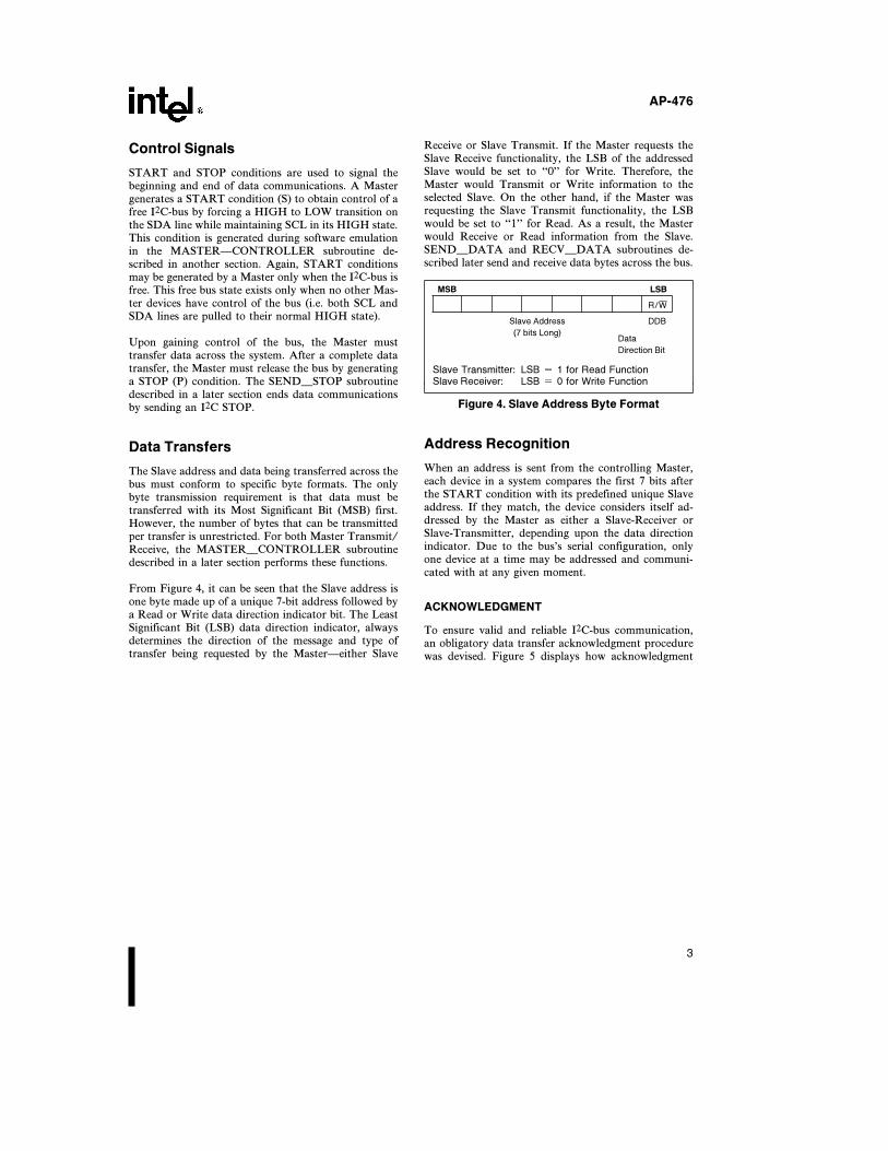
From Figure 4, it can be seen that the Slave address isone byte made up of a unique 7-bit address followed bya Read or Write data direction indicator bit. The LeastSignificant Bit (LSB) data direction indicator, alwaysdetermines the direction of the message and type oftransfer being requested by the MasterÐeither Slave
Receive or Slave Transmit. If the Master requests theSlave Receive functionality, the LSB of the addressedSlave would be set to ‘‘0’’ for Write. Therefore, theMaster would Transmit or Write information to theselected Slave. On the other hand, if the Master wasrequesting the Slave Transmit functionality, the LSBwould be set to ‘‘1’’ for Read. As a result, the Masterwould Receive or Read information from the Slave.SENDÐDATA and RECVÐDATA subroutines de-scribed later send and receive data bytes across the bus.
MSB LSB
R/W
Slave Address DDB
(7 bits Long)Data
Direction Bit
Slave Transmitter: LSB e 1 for Read FunctionSlave Receiver: LSB e 0 for Write Function
Figure 4. Slave Address Byte Format
Address Recognition
When an address is sent from the controlling Master,each device in a system compares the first 7 bits afterthe START condition with its predefined unique Slaveaddress. If they match, the device considers itself ad-dressed by the Master as either a Slave-Receiver orSlave-Transmitter, depending upon the data directionindicator. Due to the bus’s serial configuration, onlyone device at a time may be addressed and communi-cated with at any given moment.
ACKNOWLEDGMENT
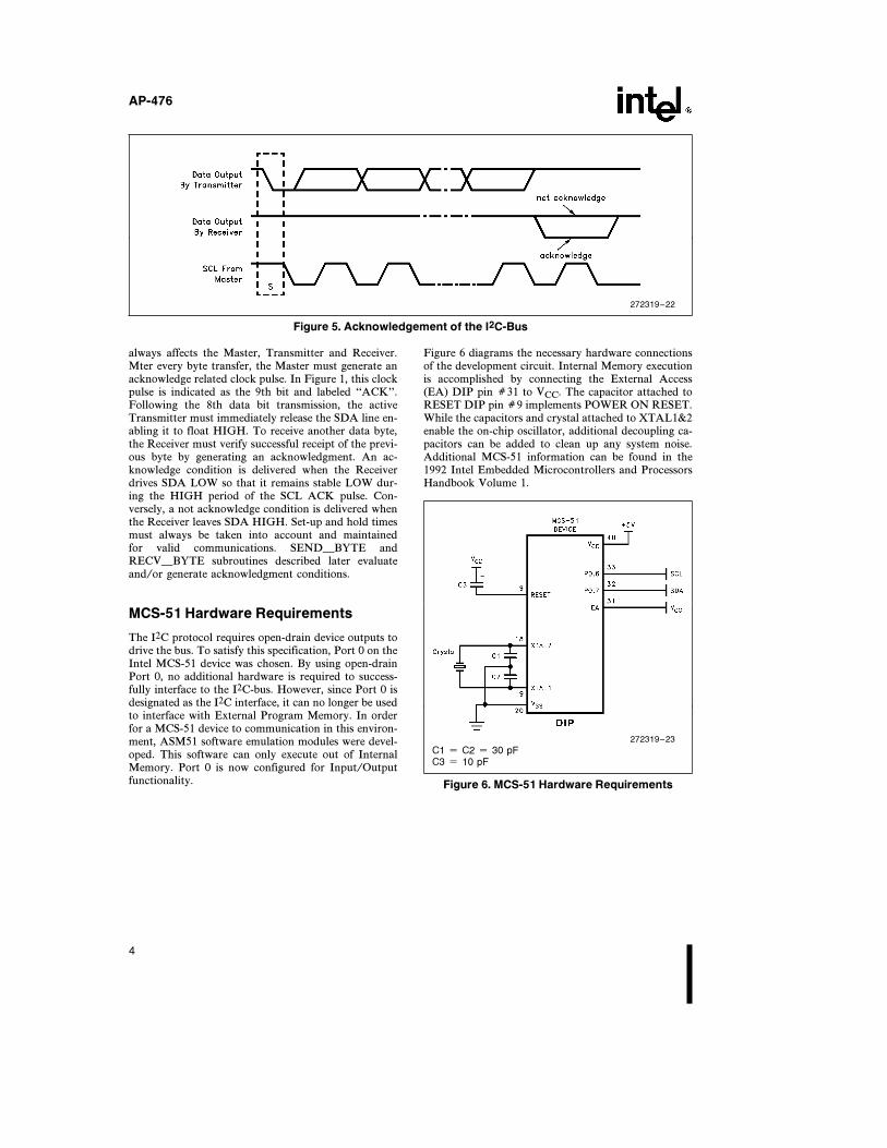
To ensure valid and reliable I2C-bus communication,an obligatory data transfer acknowledgment procedurewas devised. Figure 5 displays how acknowledgment
3
AP-476
272319–22
Figure 5. Acknowledgement of the I2C-Bus
always affects the Master, Transmitter and Receiver.Mter every byte transfer, the Master must generate anacknowledge related clock pulse. In Figure 1, this clockpulse is indicated as the 9th bit and labeled ‘‘ACK’’.Following the 8th data bit transmission, the activeTransmitter must immediately release the SDA line en-abling it to float HIGH. To receive another data byte,the Receiver must verify successful receipt of the previ-ous byte by generating an acknowledgment. An ac-knowledge condition is delivered when the Receiverdrives SDA LOW so that it remains stable LOW dur-ing the HIGH period of the SCL ACK pulse. Con-versely, a not acknowledge condition is delivered whenthe Receiver leaves SDA HIGH. Set-up and hold timesmust always be taken into account and maintainedfor valid communications. SENDÐBYTE andRECVÐBYTE subroutines described later evaluateand/or generate acknowledgment conditions.
MCS-51 Hardware Requirements
The I2C protocol requires open-drain device outputs todrive the bus. To satisfy this specification, Port 0 on theIntel MCS-51 device was chosen. By using open-drainPort 0, no additional hardware is required to success-fully interface to the I2C-bus. However, since Port 0 isdesignated as the I2C interface, it can no longer be usedto interface with External Program Memory. In orderfor a MCS-51 device to communication in this environ-ment, ASM51 software emulation modules were devel-oped. This software can only execute out of InternalMemory. Port 0 is now configured for Input/Outputfunctionality.
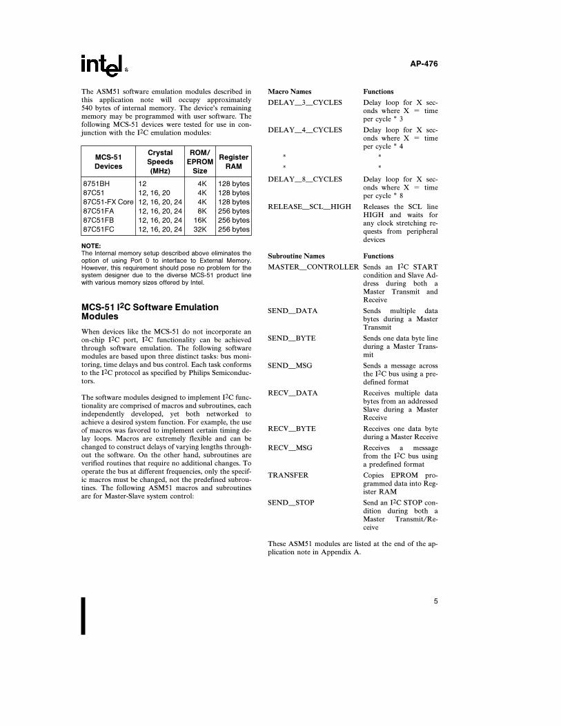
Figure 6 diagrams the necessary hardware connectionsof the development circuit. Internal Memory executionis accomplished by connecting the External Access(EA) DIP pin Ý31 to VCC. The capacitor attached toRESET DIP pin Ý9 implements POWER ON RESET.While the capacitors and crystal attached to XTAL1&2enable the on-chip oscillator, additional decoupling ca-pacitors can be added to clean up any system noise.Additional MCS-51 information can be found in the1992 Intel Embedded Microcontrollers and ProcessorsHandbook Volume 1.
272319–23
C1 e C2 e 30 pFC3 e 10 pF
Figure 6. MCS-51 Hardware Requirements
4
AP-476
The ASM51 software emulation modules described inthis application note will occupy approximately540 bytes of internal memory. The device’s remainingmemory may be programmed with user software. Thefollowing MCS-51 devices were tested for use in con-junction with the I2C emulation modules:
MCS-51Crystal ROM/
Register
DevicesSpeeds EPROM
RAM(MHz) Size
8751BH 12 4K 128 bytes
87C51 12, 16, 20 4K 128 bytes
87C51-FX Core 12, 16, 20, 24 4K 128 bytes
87C51FA 12, 16, 20, 24 8K 256 bytes
87C51FB 12, 16, 20, 24 16K 256 bytes
87C51FC 12, 16, 20, 24 32K 256 bytes
NOTE:The Internal memory setup described above eliminates theoption of using Port 0 to interface to External Memory.However, this requirement should pose no problem for thesystem designer due to the diverse MCS-51 product linewith various memory sizes offered by Intel.
MCS-51 I2C Software EmulationModules
When devices like the MCS-51 do not incorporate anon-chip I2C port, I2C functionality can be achievedthrough software emulation. The following softwaremodules are based upon three distinct tasks: bus moni-toring, time delays and bus control. Each task conformsto the I2C protocol as specified by Philips Semiconduc-tors.
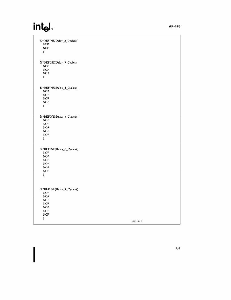
The software modules designed to implement I2C func-tionality are comprised of macros and subroutines, eachindependently developed, yet both networked toachieve a desired system function. For example, the useof macros was favored to implement certain timing de-lay loops. Macros are extremely flexible and can bechanged to construct delays of varying lengths through-out the software. On the other hand, subroutines areverified routines that require no additional changes. Tooperate the bus at different frequencies, only the specif-ic macros must be changed, not the predefined subrou-tines. The following ASM51 macros and subroutinesare for Master-Slave system control:
Macro Names Functions
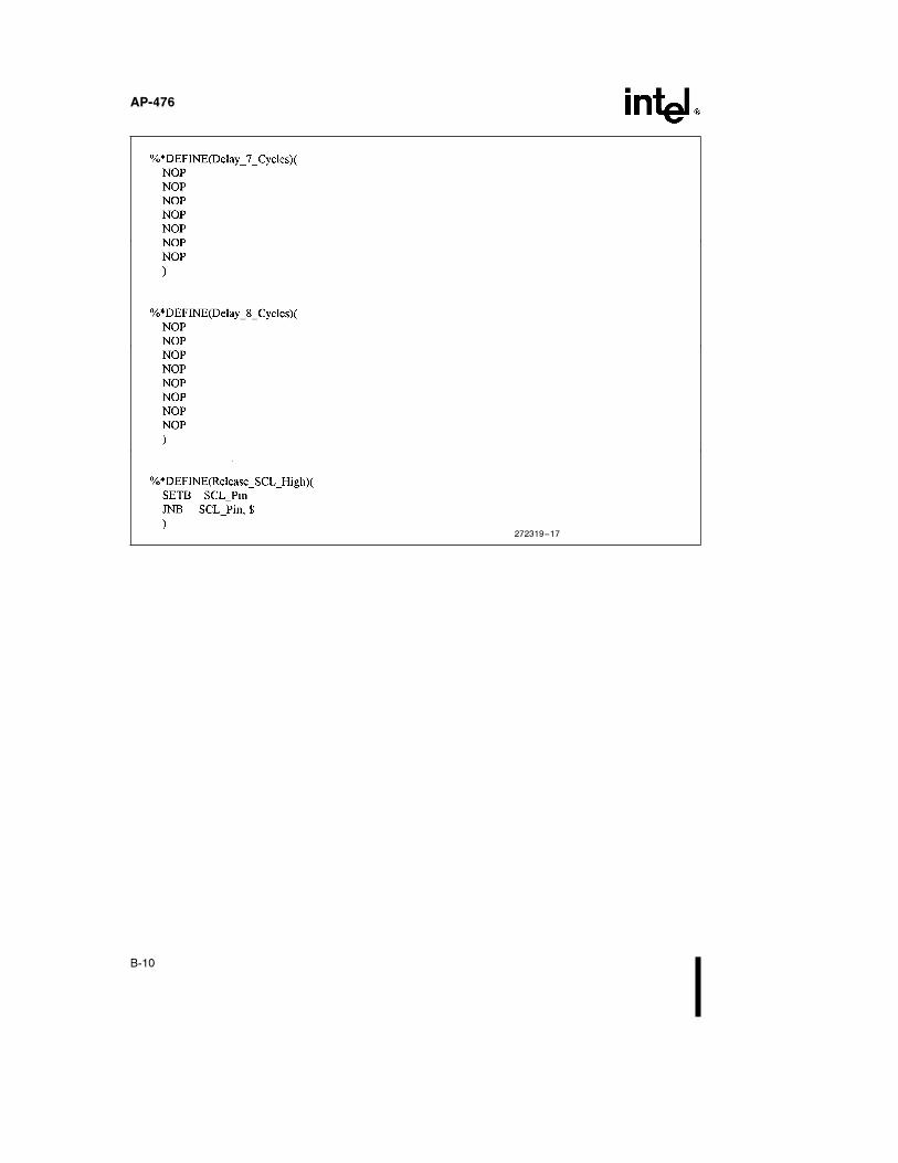
DELAYÐ3ÐCYCLES Delay loop for X sec-onds where X e timeper cycle * 3
DELAYÐ4ÐCYCLES Delay loop for X sec-onds where X e timeper cycle * 4
* ** *
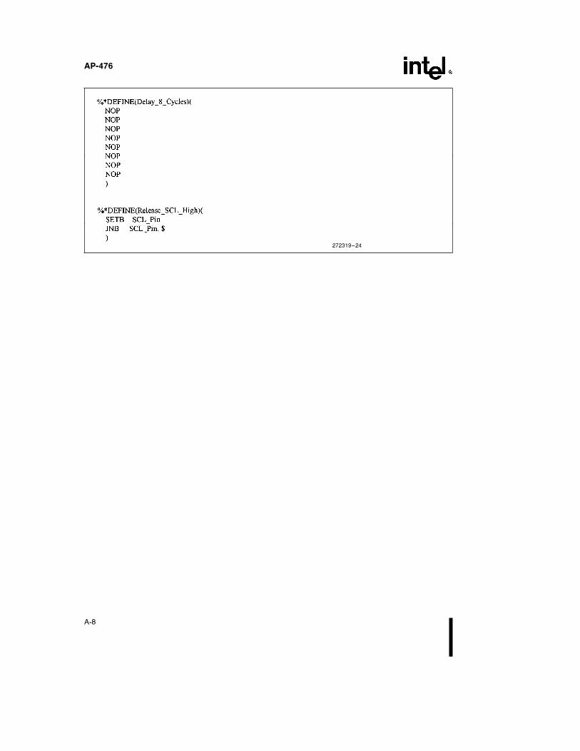
DELAYÐ8ÐCYCLES Delay loop for X sec-onds where X e timeper cycle * 8
RELEASEÐSCLÐHIGH Releases the SCL lineHIGH and waits forany clock stretching re-quests from peripheraldevices
Subroutine Names Functions
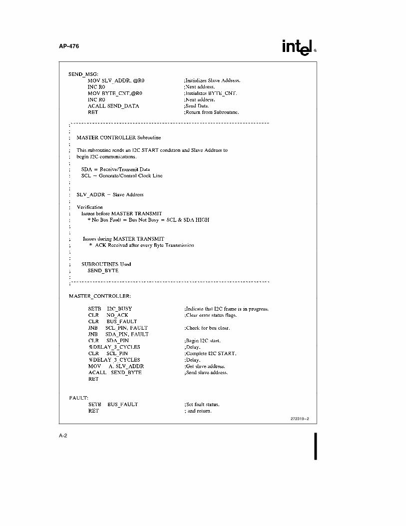
MASTERÐCONTROLLER Sends an I2C STARTcondition and Slave Ad-dress during both aMaster Transmit andReceive
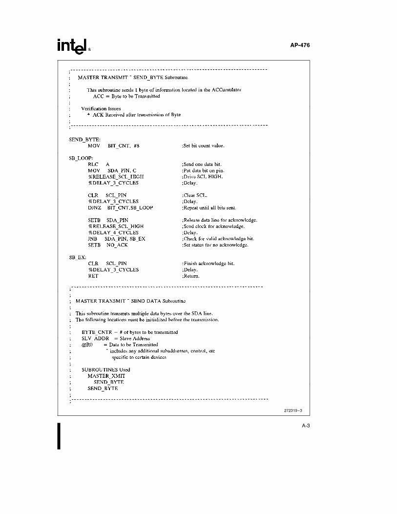
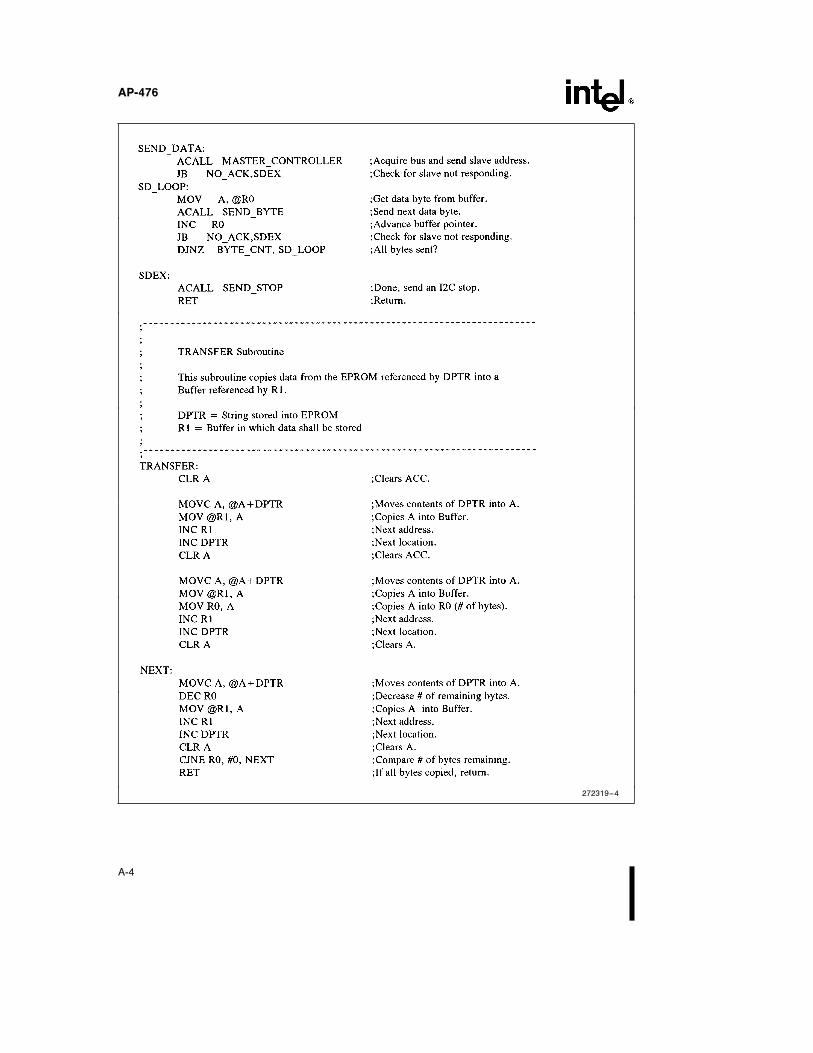
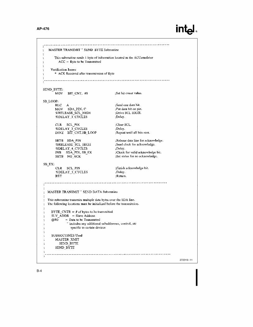
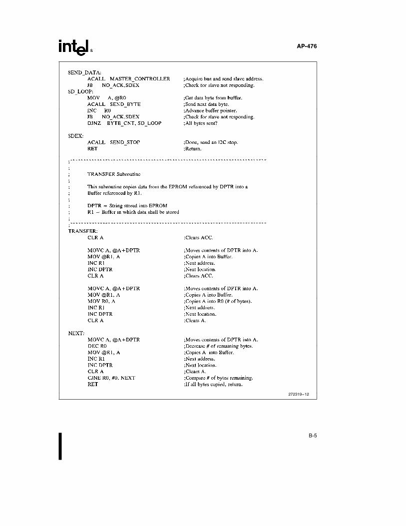
SENDÐDATA Sends multiple databytes during a MasterTransmit
SENDÐBYTE Sends one data byte lineduring a Master Trans-mit
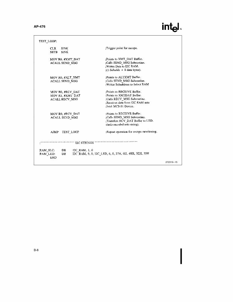
SENDÐMSG Sends a message acrossthe I2C bus using a pre-defined format
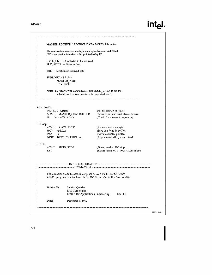
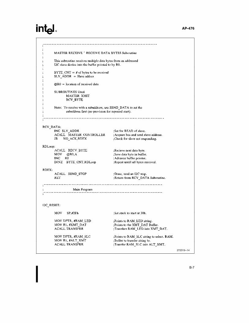
RECVÐDATA Receives multiple databytes from an addressedSlave during a MasterReceive
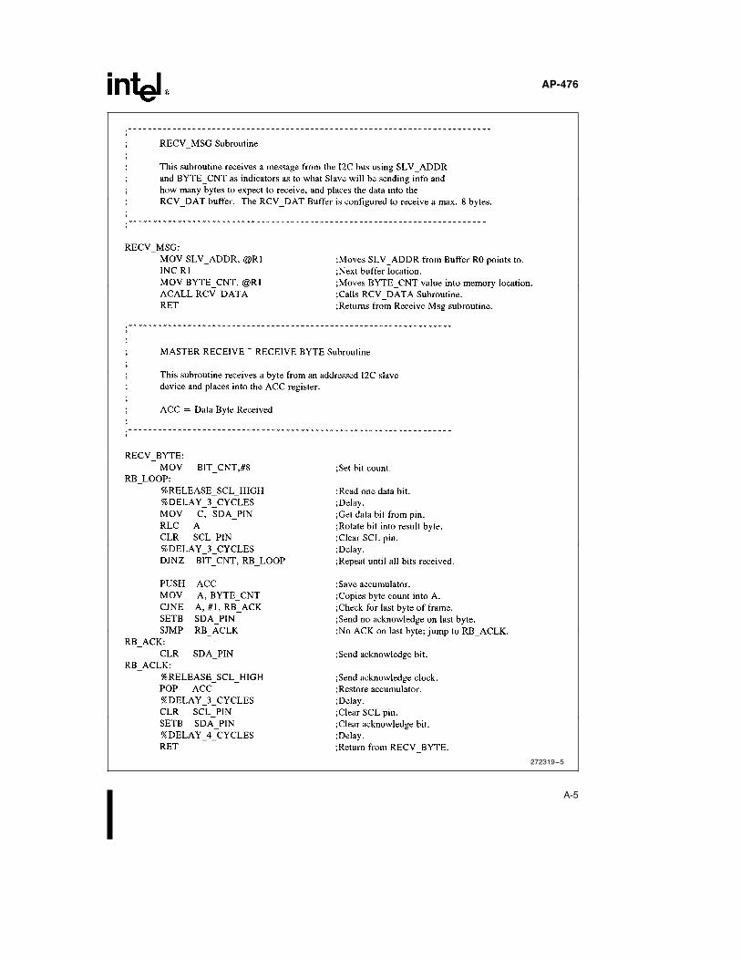
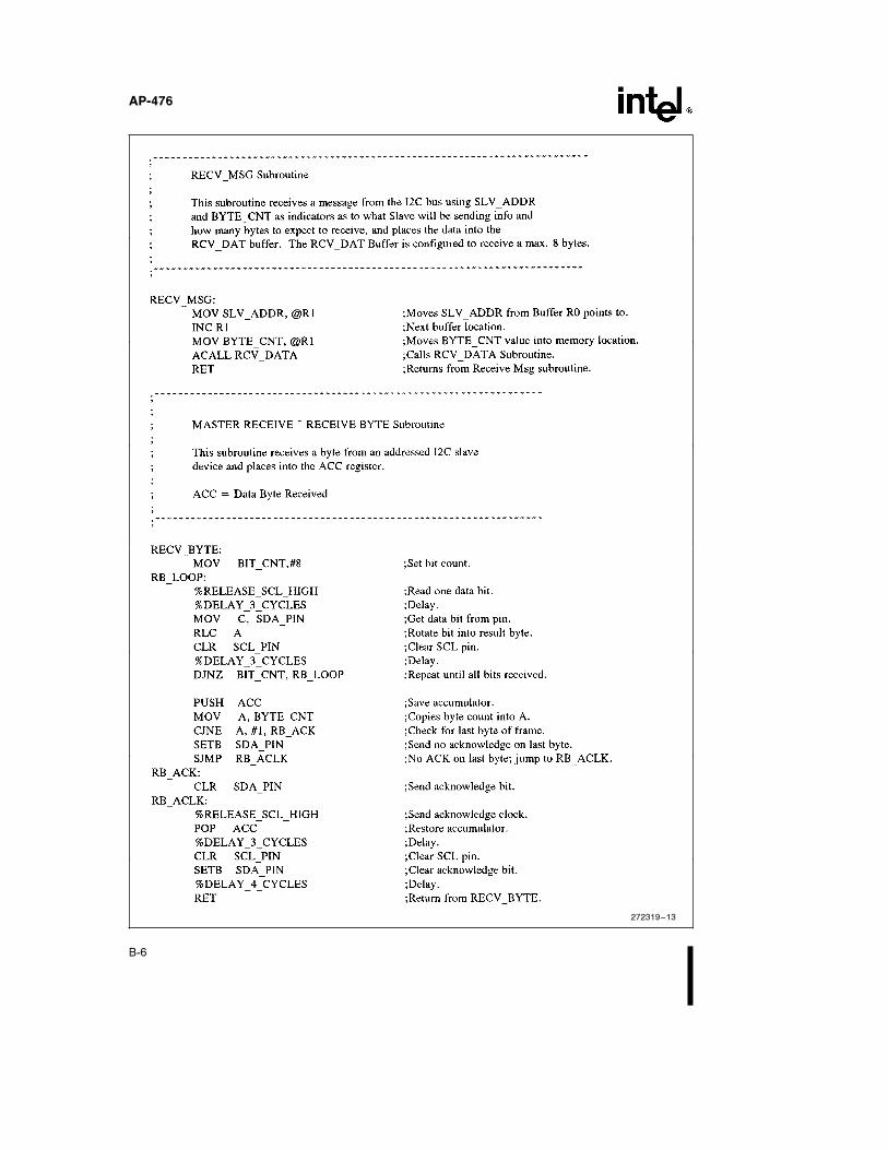
RECVÐBYTE Receives one data byteduring a Master Receive
RECVÐMSG Receives a messagefrom the I2C bus usinga predefined format
TRANSFER Copies EPROM pro-grammed data into Reg-ister RAM
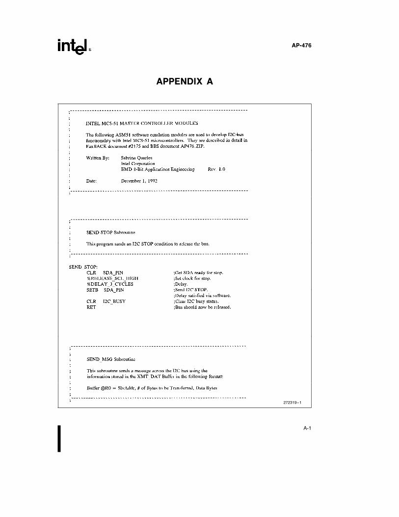
SENDÐSTOP Send an I2C STOP con-dition during both aMaster Transmit/Re-ceive
These ASM51 modules are listed at the end of the ap-plication note in Appendix A.
5
AP-476
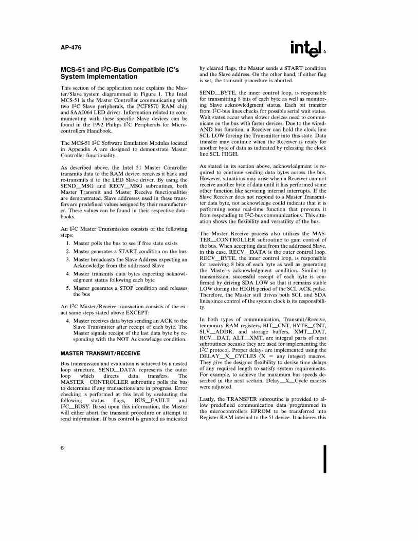
MCS-51 and I2C-Bus Compatible IC’sSystem Implementation
This section of the application note explains the Mas-ter/Slave system diagrammed in Figure 1. The IntelMCS-51 is the Master Controller communicating withtwo I2C Slave peripherals, the PCF8570 RAM chipand SAAI064 LED driver. Information related to com-municating with these specific Slave devices can befound in the 1992 Philips I2C Peripherals for Micro-controllers Handbook.
The MCS-51 I2C Software Emulation Modules locatedin Appendix A are designed to demonstrate MasterController functionality.
As described above, the Intel 51 Master Controllertransmits data to the RAM device, receives it back andre-transmits it to the LED Slave driver. By using theSENDÐMSG and RECVÐMSG subroutines, bothMaster Transmit and Master Receive functionalitiesare demonstrated. Slave addresses used in these trans-fers are predefined values assigned by their manufactur-er. These values can be found in their respective data-books.
An I2C Master Transmission consists of the followingsteps:
1. Master polls the bus to see if free state exists
2. Master generates a START condition on the bus
3. Master broadcasts the Slave Address expecting anAcknowledge from the addressed Slave
4. Master transmits data bytes expecting acknowl-edgment status following each byte
5. Master generates a STOP condition and releasesthe bus
An I2C Master/Receive transaction consists of the ex-act same steps stated above EXCEPT:
4. Master receives data bytes sending an ACK to theSlave Transmitter after receipt of each byte. TheMaster signals receipt of the last data byte by re-sponding with the NOT Acknowledge condition.
MASTER TRANSMIT/RECEIVE
Bus transmission and evaluation is achieved by a nestedloop structure. SENDÐDATA represents the outerloop which directs data transfers. TheMASTERÐCONTROLLER subroutine polls the busto determine if any transactions are in progress. Errorchecking is performed at this level by evaluating thefollowing status flags, BUSÐFAULT andI2CÐBUSY. Based upon this information, the Masterwill either abort the transmit procedure or attempt tosend information. If bus control is granted as indicated
by cleared flags, the Master sends a START conditionand the Slave address. On the other hand, if either flagis set, the transmit procedure is aborted.
SENDÐBYTE, the inner control loop, is responsiblefor transmitting 8 bits of each byte as well as monitor-ing Slave acknowledgment status. Each bit transferfrom I2C-bus lines checks for possible serial wait states.Wait states occur when slower devices need to commu-nicate on the bus with faster devices. Due to the wired-AND bus function, a Receiver can hold the clock lineSCL LOW forcing the Transmitter into this state. Datatransfer may continue when the Receiver is ready foranother byte of data as indicated by releasing the clockline SCL HIGH.
As stated in its section above, acknowledgment is re-quired to continue sending data bytes across the bus.However, situations may arise when a Receiver can notreceive another byte of data until it has performed someother function like servicing internal interrupts. If theSlave Receiver does not respond to a Master Transmit-ter data byte, not acknowledge could indicate that it isperforming some real-time function that prevents itfrom responding to I2C-bus communications. This situ-ation shows the flexibility and versatility of the bus.
The Master Receive process also utilizes the MAS-TERÐCONTROLLER subroutine to gain control ofthe bus. When accepting data from the addressed Slave,in this case, RECVÐDATA is the outer control loop.RECVÐBYTE, the inner control loop, is responsiblefor receiving 8 bits of each byte as well as generatingthe Master’s acknowledgment condition. Similar totransmission, successful receipt of each byte is con-firmed by driving SDA LOW so that it remains stableLOW during the HIGH period of the SCL ACK pulse.Therefore, the Master still drives both SCL and SDAlines since control of the system clock is its responsibili-ty.
In both types of communication, Transmit/Receive,temporary RAM registers, BITÐCNT, BYTEÐCNT,SLVÐADDR, and storage buffers, XMTÐDAT,RCVÐDAT, ALTÐXMT, are integral parts of mostsubroutines because they are used for implementing theI2C protocol. Proper delays are implemented using theDELAYÐXÐCYCLES (X e any integer) macros.They give the designer flexibility to devise time delaysof any required length to satisfy system requirements.For example, to achieve the maximum bus speeds de-scribed in the next section, DelayÐXÐCycle macroswere adjusted.
Lastly, the TRANSFER subroutine is provided to al-low predefined communication data programmed inthe microcontrollers EPROM to be transferred intoRegister RAM internal to the 51 device. It achieves this
6
AP-476
when used in conjunction with the SENDÐMSG andRECVÐMSG subroutines. However, when utilizingTRANSFER, the designer must conform their designto existing device Register RAM availability and to thefollowing message format:
Slave Address, Ý of Bytes to be Transmitted/Received, DataBytes (For Transmit Only)
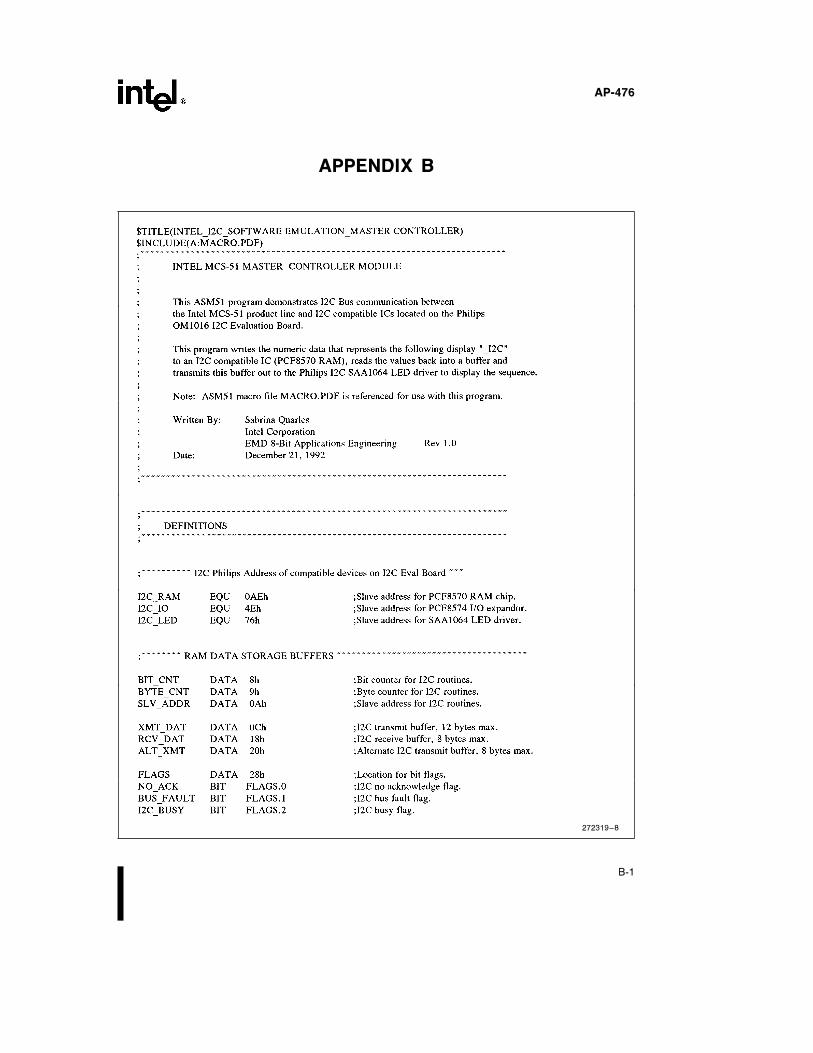
The ASM-51 program demonstrating a complete Mas-ter Controller system is listed at the end of the applica-tion note in Appendix B. It writes the numeric datathat represents the following display ‘‘ÐI2C’’ to an I2Ccompatible IC (PCF8570 RAM), reads the values backinto a buffer and transmits this buffer out to the PhilipsI2C SAA1064 LED driver to display the sequence.
I2C Software Emulation Performance
As demonstrated above, the Intel MCS-51 product linecan successfully implement the I2C Master Controllerfunctionality while maintaining data integrity and reli-able performance. The system outlined in Figure 1 wasevaluated for maximum bus performance and adher-ence to all I2C-bus specifications. Performance charac-terization was conducted at various crystal speeds onall devices listed in the MCS-51 Hardware Require-ments section of this application note.
When designing I2C software emulation systems, keepin mind that the designer has the flexibility to imple-ment large frequency ranges up to the I2C-bus maxi-mum. However, by making software changes to adjustbus frequencies, the newly modified program may nolonger meet required specifications and desired reliabil-ity standards. Therefore, designers should first alwaystake into consideration the bus performance level theywant to reach. After deciding this, an appropriate crys-tal can be chosen to achieve that implementation speed.The table below gives a few examples of system per-formance for two of the MCS-51 devices:
MCS-51 CrystalI2C Bus
Devices SpeedMaximum
Performance
8751BH 12 MHz 66.7 kHz
87C51 (FX-Core) 24 MHz 80.0 kHz
CONCLUSION
As a result of this evaluation, Intel MCS-51 microcon-trollers can be successfully interfaced to an I2C-bus sys-tem as a Master controller. The interface communicatesby ASM51 software emulation modules that have beentested on a wide array of I2C devices ranging from seri-al RAMS, Displays and a DTMF generators. No com-patibility problems have been seen to date. Therefore,when considering the implementation of your next I2C-bus Master Controller serial communication system,you have the option of using the Intel MCS-51 ProductLine.
REFERENCES
I2CBITS.ASM, G. Goodhue, Philips Semiconductors,August 1992.
The I2C-Bus and How to Use It (Including Specifica-tion), Philips Semiconductors, January 1992.
I2C Peripherals for Microcontrollers, Philips Semicon-ductors, 1992 Data Handbook.
OM1016 I2C Evaluation Board, E. Rodgers and G.Moss, Philips Components Applications Lab Auck-land, New Zealand.
Programming the I2C Interface, Mitchell Kahn, SeniorEngineer, Intel Corporation.
7

AP-476
APPENDIX A
272319–1
A-1
AP-476
272319–2
A-2
AP-476
272319–3
A-3
AP-476
272319–4
A-4
AP-476
272319–5
A-5
AP-476
272319–6
A-6
AP-476
272319–7
A-7
AP-476
272319–24
A-8
AP-476
APPENDIX B
272319–8
B-1
AP-476
272319–9
B-2
AP-476
272319–10
B-3
AP-476
272319–11
B-4
AP-476
272319–12
B-5
AP-476
272319–13
B-6
AP-476
272319–14
B-7
AP-476
272319–15
B-8

AP-476
AP-476
272319–17
B-10