how to build an arduino-compatible physical computing ... to build... · if your breadboard looks...
TRANSCRIPT
DaleWheat.com 1 September 2009
How to Build an Arduino-compatible Physical Computing Platform on a
Solderless Breadboard
Build your own Arduino-compatible microcomputer in about an h our – with your bare hands !
Dale Wheat – Version 1.1 – September 2009
Prerequisites: Personal computer running the Arduino IDE (see http://arduino.cc for details), USB port
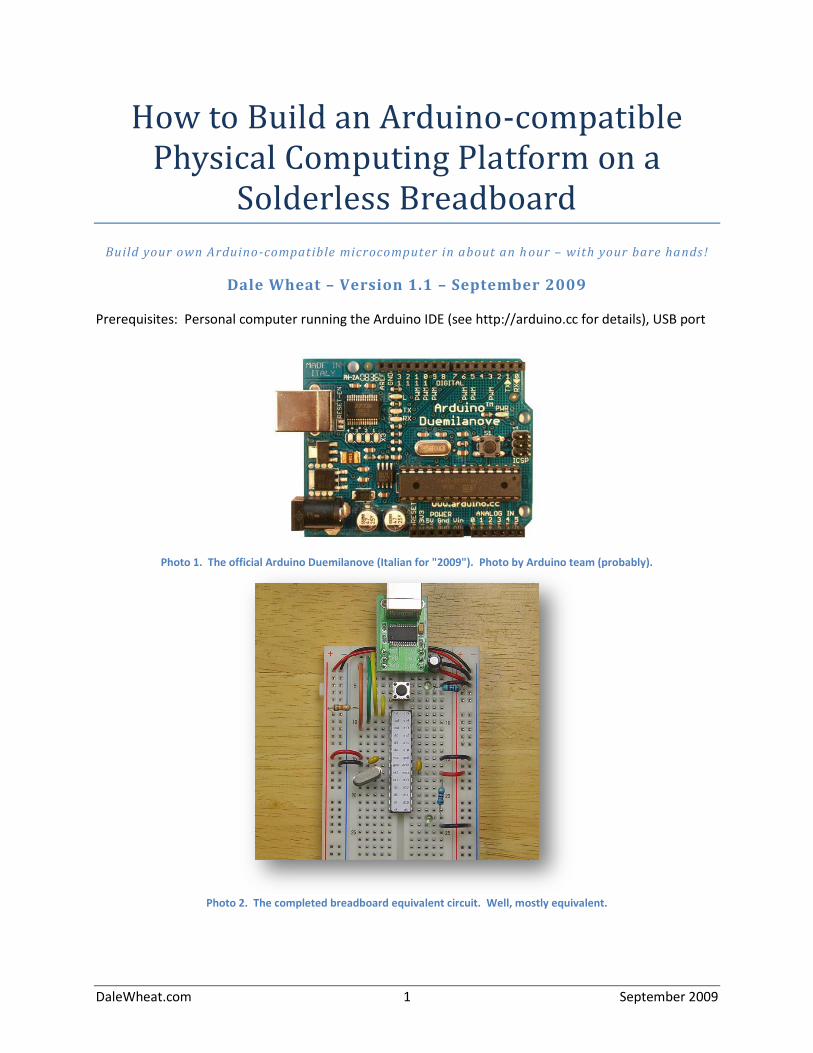
Photo 1. The official Arduino Duemilanove (Italian for "2009"). Photo by Arduino team (probably).
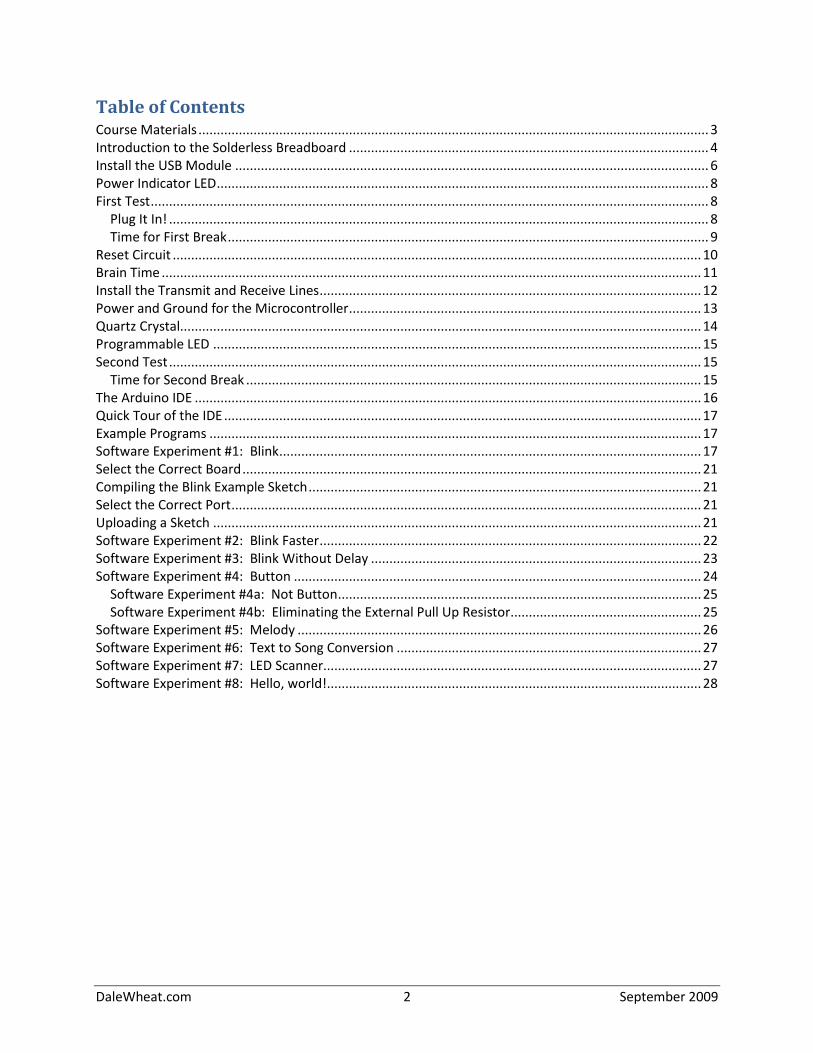
Photo 2. The completed breadboard equivalent circuit. Well, mostly equivalent.
DaleWheat.com 2 September 2009
Table of Contents Course Materials ........................................................................................................................................... 3 Introduction to the Solderless Breadboard .................................................................................................. 4 Install the USB Module ................................................................................................................................. 6 Power Indicator LED ...................................................................................................................................... 8 First Test ........................................................................................................................................................ 8
Plug It In! ................................................................................................................................................... 8 Time for First Break ................................................................................................................................... 9
Reset Circuit ................................................................................................................................................ 10 Brain Time ................................................................................................................................................... 11 Install the Transmit and Receive Lines ........................................................................................................ 12 Power and Ground for the Microcontroller ................................................................................................ 13 Quartz Crystal.............................................................................................................................................. 14 Programmable LED ..................................................................................................................................... 15 Second Test ................................................................................................................................................. 15
Time for Second Break ............................................................................................................................ 15 The Arduino IDE .......................................................................................................................................... 16 Quick Tour of the IDE .................................................................................................................................. 17 Example Programs ...................................................................................................................................... 17 Software Experiment #1: Blink ................................................................................................................... 17 Select the Correct Board ............................................................................................................................. 21 Compiling the Blink Example Sketch ........................................................................................................... 21 Select the Correct Port ................................................................................................................................ 21 Uploading a Sketch ..................................................................................................................................... 21 Software Experiment #2: Blink Faster ........................................................................................................ 22 Software Experiment #3: Blink Without Delay .......................................................................................... 23 Software Experiment #4: Button ............................................................................................................... 24
Software Experiment #4a: Not Button ................................................................................................... 25 Software Experiment #4b: Eliminating the External Pull Up Resistor.................................................... 25
Software Experiment #5: Melody .............................................................................................................. 26 Software Experiment #6: Text to Song Conversion ................................................................................... 27 Software Experiment #7: LED Scanner....................................................................................................... 27 Software Experiment #8: Hello, world!...................................................................................................... 28
DaleWheat.com 3 September 2009
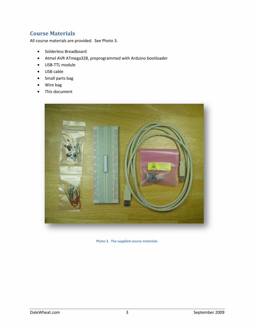
Course Materials All course materials are provided. See Photo 3.
Solderless Breadboard
Atmel AVR ATmega328, preprogrammed with Arduino bootloader
USB-TTL module
USB cable
Small parts bag
Wire bag
This document
Photo 3. The supplied course materials.
DaleWheat.com 4 September 2009
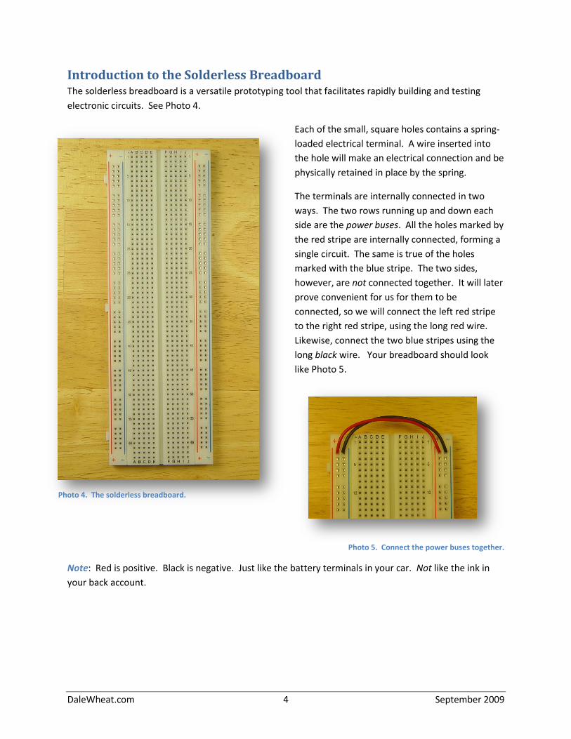
Introduction to the Solderless Breadboard The solderless breadboard is a versatile prototyping tool that facilitates rapidly building and testing
electronic circuits. See Photo 4.
Each of the small, square holes contains a spring-
loaded electrical terminal. A wire inserted into
the hole will make an electrical connection and be
physically retained in place by the spring.
The terminals are internally connected in two
ways. The two rows running up and down each
side are the power buses. All the holes marked by
the red stripe are internally connected, forming a
single circuit. The same is true of the holes
marked with the blue stripe. The two sides,
however, are not connected together. It will later
prove convenient for us for them to be
connected, so we will connect the left red stripe
to the right red stripe, using the long red wire.
Likewise, connect the two blue stripes using the
long black wire. Your breadboard should look
like Photo 5.
Photo 5. Connect the power buses together.
Note: Red is positive. Black is negative. Just like the battery terminals in your car. Not like the ink in
your back account.
Photo 4. The solderless breadboard.
DaleWheat.com 5 September 2009
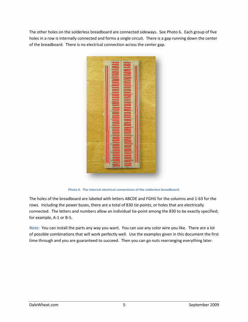
The other holes on the solderless breadboard are connected sideways. See Photo 6. Each group of five
holes in a row is internally connected and forms a single circuit. There is a gap running down the center
of the breadboard. There is no electrical connection across the center gap.
Photo 6. The internal electrical connections of the solderless breadboard.
The holes of the breadboard are labeled with letters ABCDE and FGHIJ for the columns and 1-63 for the
rows. Including the power buses, there are a total of 830 tie-points, or holes that are electrically
connected. The letters and numbers allow an individual tie-point among the 830 to be exactly specified;
for example, A-1 or B-5.
Note: You can install the parts any way you want. You can use any color wire you like. There are a lot
of possible combinations that will work perfectly well. Use the examples given in this document the first
time through and you are guaranteed to succeed. Then you can go nuts rearranging everything later.
DaleWheat.com 6 September 2009
Install the USB Module To install the USB module, carefully remove the USB module from the pink static bag. Hold the module
by the board edges. Try not to touch the pins. The module is fairly hardy but can be damaged by static
electricity.
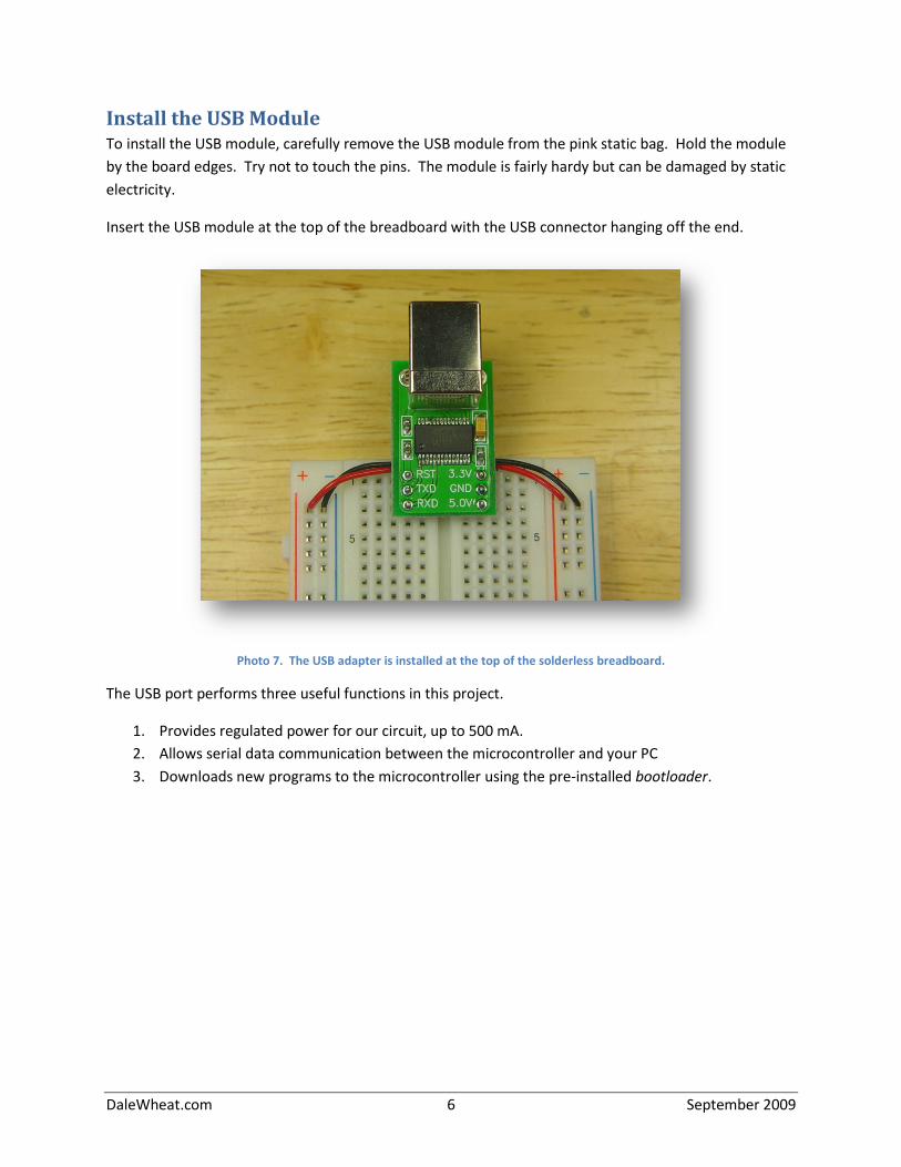
Insert the USB module at the top of the breadboard with the USB connector hanging off the end.
Photo 7. The USB adapter is installed at the top of the solderless breadboard.
The USB port performs three useful functions in this project.
1. Provides regulated power for our circuit, up to 500 mA.
2. Allows serial data communication between the microcontroller and your PC
3. Downloads new programs to the microcontroller using the pre-installed bootloader.
DaleWheat.com 7 September 2009
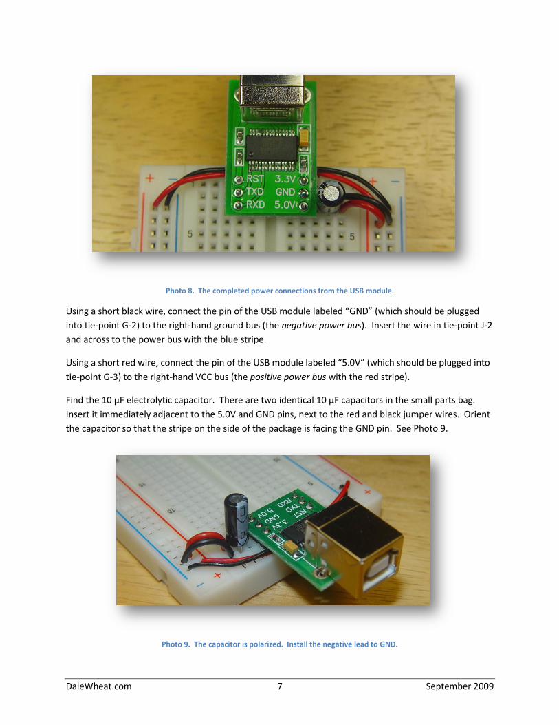
Photo 8. The completed power connections from the USB module.
Using a short black wire, connect the pin of the USB module labeled “GND” (which should be plugged
into tie-point G-2) to the right-hand ground bus (the negative power bus). Insert the wire in tie-point J-2
and across to the power bus with the blue stripe.
Using a short red wire, connect the pin of the USB module labeled “5.0V” (which should be plugged into
tie-point G-3) to the right-hand VCC bus (the positive power bus with the red stripe).
Find the 10 μF electrolytic capacitor. There are two identical 10 μF capacitors in the small parts bag.
Insert it immediately adjacent to the 5.0V and GND pins, next to the red and black jumper wires. Orient
the capacitor so that the stripe on the side of the package is facing the GND pin. See Photo 9.
Photo 9. The capacitor is polarized. Install the negative lead to GND.
DaleWheat.com 8 September 2009
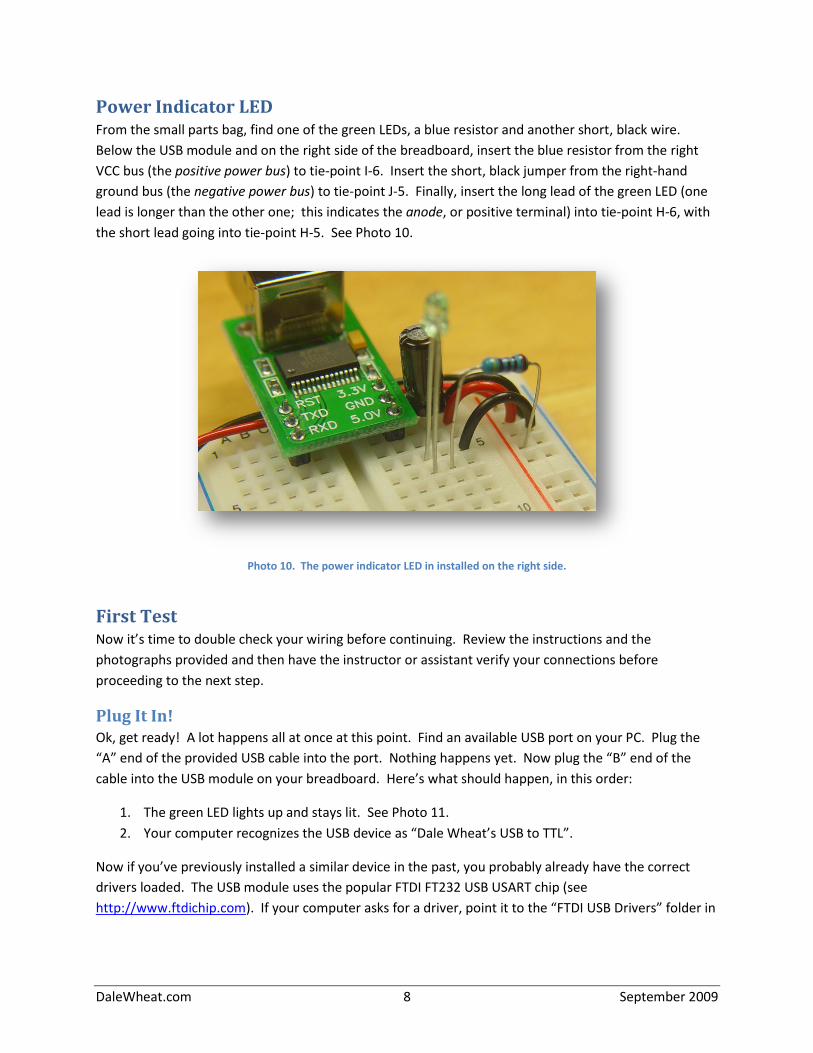
Power Indicator LED From the small parts bag, find one of the green LEDs, a blue resistor and another short, black wire.
Below the USB module and on the right side of the breadboard, insert the blue resistor from the right
VCC bus (the positive power bus) to tie-point I-6. Insert the short, black jumper from the right-hand
ground bus (the negative power bus) to tie-point J-5. Finally, insert the long lead of the green LED (one
lead is longer than the other one; this indicates the anode, or positive terminal) into tie-point H-6, with
the short lead going into tie-point H-5. See Photo 10.
Photo 10. The power indicator LED in installed on the right side.
First Test Now it’s time to double check your wiring before continuing. Review the instructions and the
photographs provided and then have the instructor or assistant verify your connections before
proceeding to the next step.
Plug It In! Ok, get ready! A lot happens all at once at this point. Find an available USB port on your PC. Plug the
“A” end of the provided USB cable into the port. Nothing happens yet. Now plug the “B” end of the
cable into the USB module on your breadboard. Here’s what should happen, in this order:
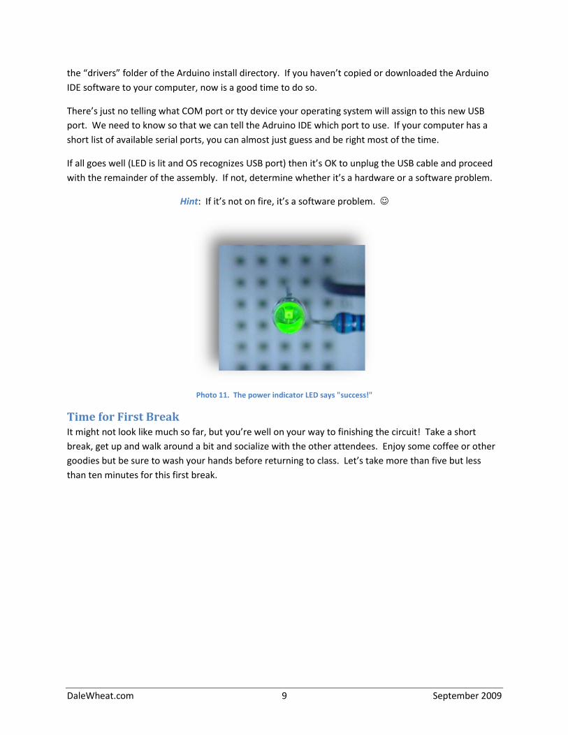
1. The green LED lights up and stays lit. See Photo 11.
2. Your computer recognizes the USB device as “Dale Wheat’s USB to TTL”.
Now if you’ve previously installed a similar device in the past, you probably already have the correct
drivers loaded. The USB module uses the popular FTDI FT232 USB USART chip (see
http://www.ftdichip.com). If your computer asks for a driver, point it to the “FTDI USB Drivers” folder in
DaleWheat.com 9 September 2009
the “drivers” folder of the Arduino install directory. If you haven’t copied or downloaded the Arduino
IDE software to your computer, now is a good time to do so.
There’s just no telling what COM port or tty device your operating system will assign to this new USB
port. We need to know so that we can tell the Adruino IDE which port to use. If your computer has a
short list of available serial ports, you can almost just guess and be right most of the time.
If all goes well (LED is lit and OS recognizes USB port) then it’s OK to unplug the USB cable and proceed
with the remainder of the assembly. If not, determine whether it’s a hardware or a software problem.
Hint: If it’s not on fire, it’s a software problem.
Photo 11. The power indicator LED says "success!"
Time for First Break It might not look like much so far, but you’re well on your way to finishing the circuit! Take a short
break, get up and walk around a bit and socialize with the other attendees. Enjoy some coffee or other
goodies but be sure to wash your hands before returning to class. Let’s take more than five but less
than ten minutes for this first break.
DaleWheat.com 10 September 2009
Reset Circuit One of the nice things about the current Arduino design is that it can be remotely reset by the host PC.
You can also reset it locally using a push button. We duplicate both features in this circuit.
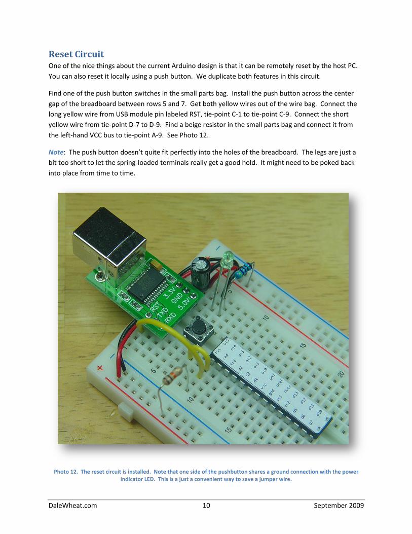
Find one of the push button switches in the small parts bag. Install the push button across the center
gap of the breadboard between rows 5 and 7. Get both yellow wires out of the wire bag. Connect the
long yellow wire from USB module pin labeled RST, tie-point C-1 to tie-point C-9. Connect the short
yellow wire from tie-point D-7 to D-9. Find a beige resistor in the small parts bag and connect it from
the left-hand VCC bus to tie-point A-9. See Photo 12.
Note: The push button doesn’t quite fit perfectly into the holes of the breadboard. The legs are just a
bit too short to let the spring-loaded terminals really get a good hold. It might need to be poked back
into place from time to time.
Photo 12. The reset circuit is installed. Note that one side of the pushbutton shares a ground connection with the power indicator LED. This is a just a convenient way to save a jumper wire.
DaleWheat.com 11 September 2009
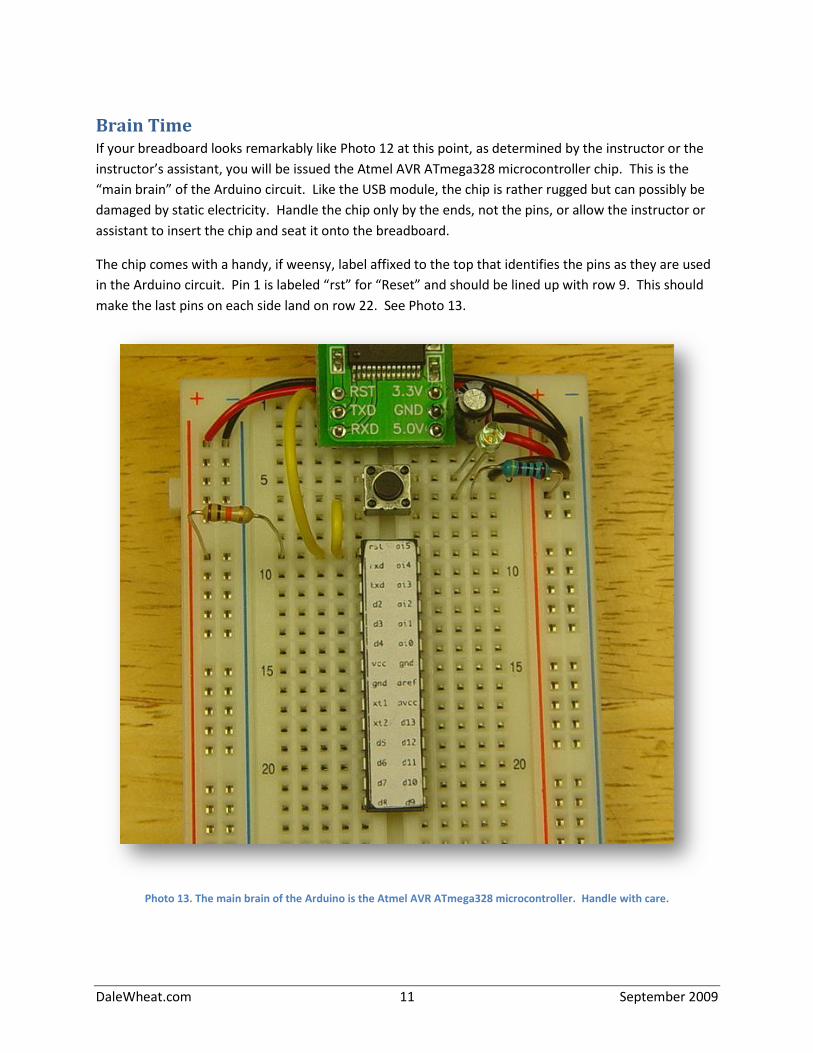
Brain Time If your breadboard looks remarkably like Photo 12 at this point, as determined by the instructor or the
instructor’s assistant, you will be issued the Atmel AVR ATmega328 microcontroller chip. This is the
“main brain” of the Arduino circuit. Like the USB module, the chip is rather rugged but can possibly be
damaged by static electricity. Handle the chip only by the ends, not the pins, or allow the instructor or
assistant to insert the chip and seat it onto the breadboard.
The chip comes with a handy, if weensy, label affixed to the top that identifies the pins as they are used
in the Arduino circuit. Pin 1 is labeled “rst” for “Reset” and should be lined up with row 9. This should
make the last pins on each side land on row 22. See Photo 13.
Photo 13. The main brain of the Arduino is the Atmel AVR ATmega328 microcontroller. Handle with care.
DaleWheat.com 12 September 2009
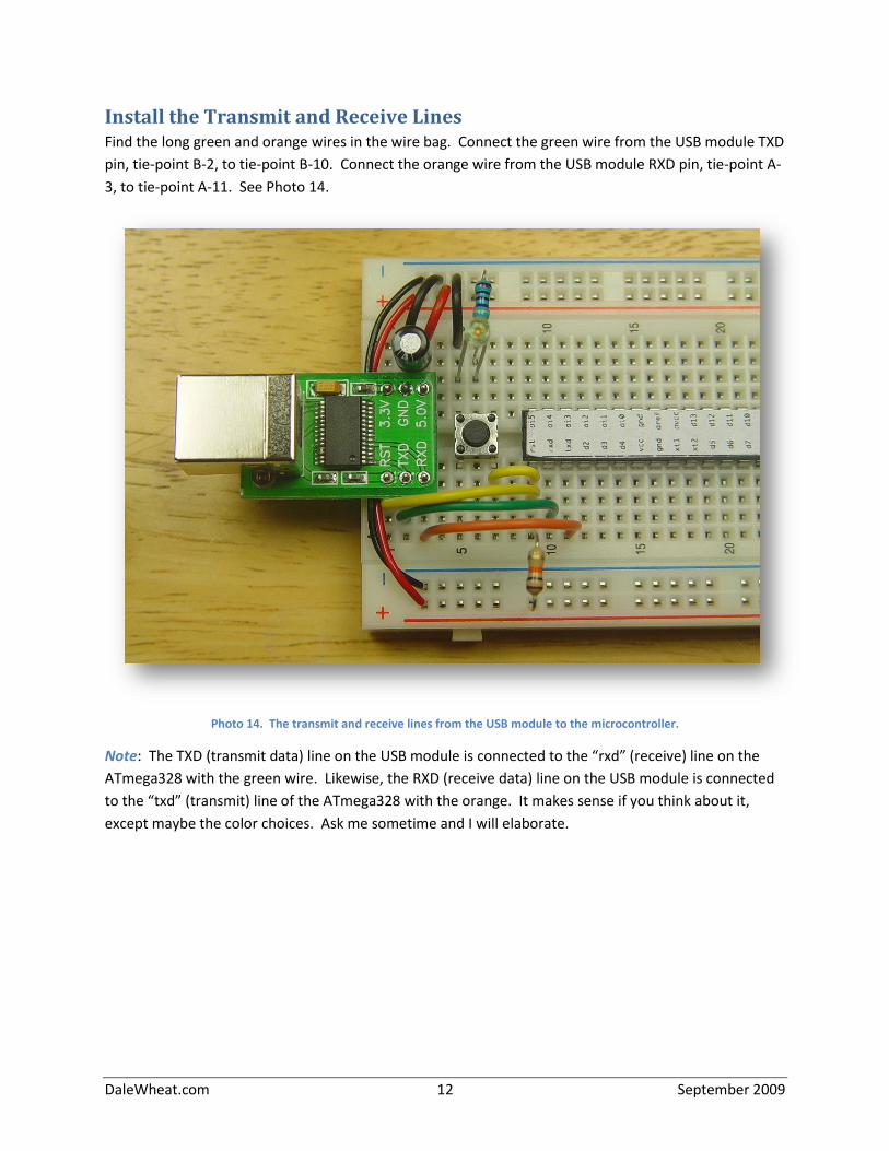
Install the Transmit and Receive Lines Find the long green and orange wires in the wire bag. Connect the green wire from the USB module TXD
pin, tie-point B-2, to tie-point B-10. Connect the orange wire from the USB module RXD pin, tie-point A-
3, to tie-point A-11. See Photo 14.
Photo 14. The transmit and receive lines from the USB module to the microcontroller.
Note: The TXD (transmit data) line on the USB module is connected to the “rxd” (receive) line on the
ATmega328 with the green wire. Likewise, the RXD (receive data) line on the USB module is connected
to the “txd” (transmit) line of the ATmega328 with the orange. It makes sense if you think about it,
except maybe the color choices. Ask me sometime and I will elaborate.
DaleWheat.com 13 September 2009
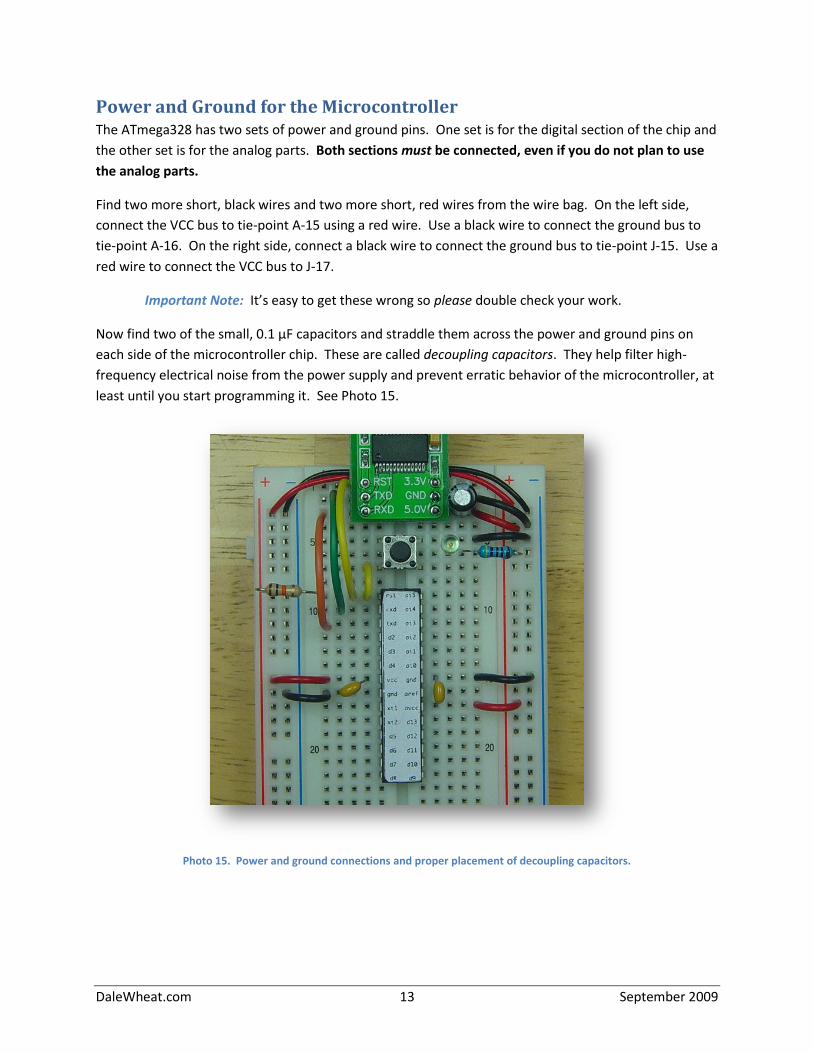
Power and Ground for the Microcontroller The ATmega328 has two sets of power and ground pins. One set is for the digital section of the chip and
the other set is for the analog parts. Both sections must be connected, even if you do not plan to use
the analog parts.
Find two more short, black wires and two more short, red wires from the wire bag. On the left side,
connect the VCC bus to tie-point A-15 using a red wire. Use a black wire to connect the ground bus to
tie-point A-16. On the right side, connect a black wire to connect the ground bus to tie-point J-15. Use a
red wire to connect the VCC bus to J-17.
Important Note: It’s easy to get these wrong so please double check your work.
Now find two of the small, 0.1 μF capacitors and straddle them across the power and ground pins on
each side of the microcontroller chip. These are called decoupling capacitors. They help filter high-
frequency electrical noise from the power supply and prevent erratic behavior of the microcontroller, at
least until you start programming it. See Photo 15.
Photo 15. Power and ground connections and proper placement of decoupling capacitors.
DaleWheat.com 14 September 2009
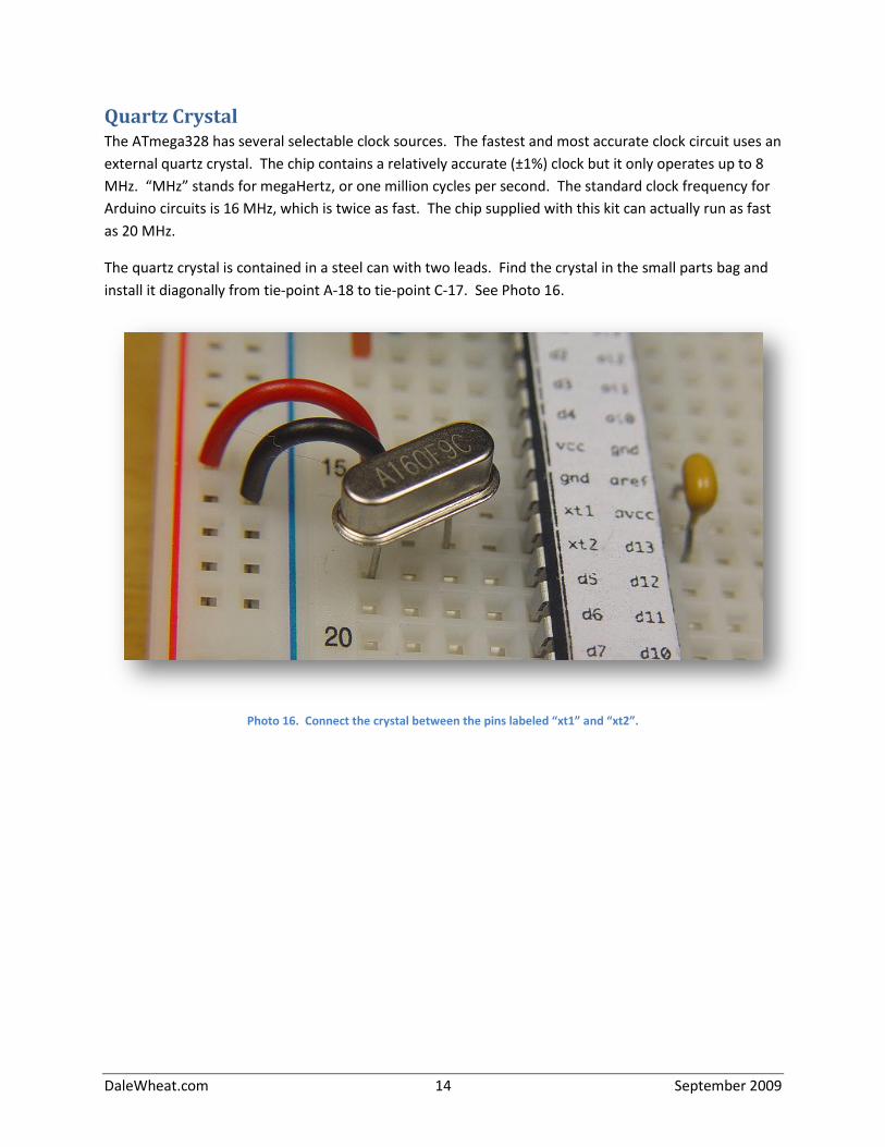
Quartz Crystal The ATmega328 has several selectable clock sources. The fastest and most accurate clock circuit uses an
external quartz crystal. The chip contains a relatively accurate (±1%) clock but it only operates up to 8
MHz. “MHz” stands for megaHertz, or one million cycles per second. The standard clock frequency for
Arduino circuits is 16 MHz, which is twice as fast. The chip supplied with this kit can actually run as fast
as 20 MHz.
The quartz crystal is contained in a steel can with two leads. Find the crystal in the small parts bag and
install it diagonally from tie-point A-18 to tie-point C-17. See Photo 16.
Photo 16. Connect the crystal between the pins labeled “xt1” and “xt2”.
DaleWheat.com 15 September 2009
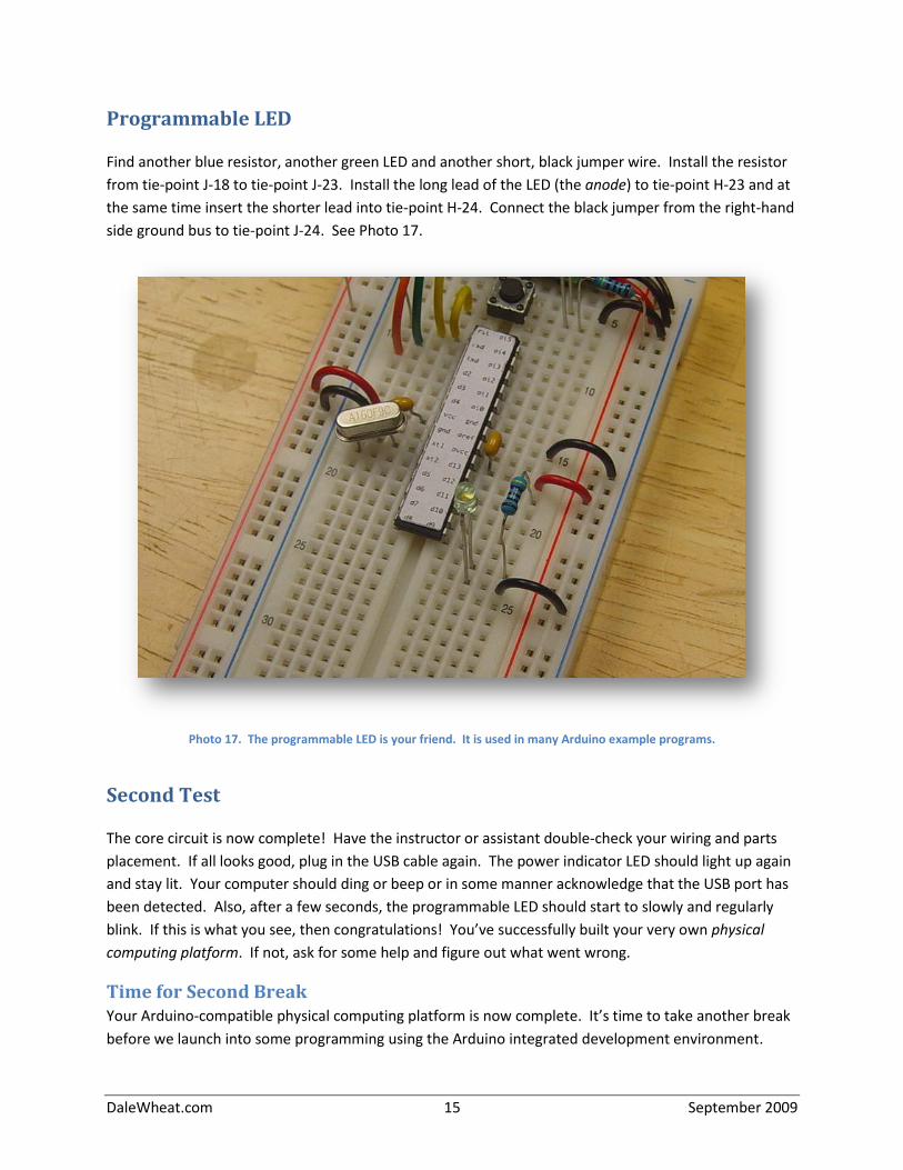
Programmable LED
Find another blue resistor, another green LED and another short, black jumper wire. Install the resistor
from tie-point J-18 to tie-point J-23. Install the long lead of the LED (the anode) to tie-point H-23 and at
the same time insert the shorter lead into tie-point H-24. Connect the black jumper from the right-hand
side ground bus to tie-point J-24. See Photo 17.
Photo 17. The programmable LED is your friend. It is used in many Arduino example programs.
Second Test
The core circuit is now complete! Have the instructor or assistant double-check your wiring and parts
placement. If all looks good, plug in the USB cable again. The power indicator LED should light up again
and stay lit. Your computer should ding or beep or in some manner acknowledge that the USB port has
been detected. Also, after a few seconds, the programmable LED should start to slowly and regularly
blink. If this is what you see, then congratulations! You’ve successfully built your very own physical
computing platform. If not, ask for some help and figure out what went wrong.
Time for Second Break Your Arduino-compatible physical computing platform is now complete. It’s time to take another break
before we launch into some programming using the Arduino integrated development environment.
DaleWheat.com 16 September 2009
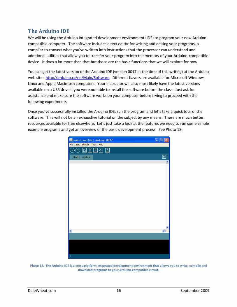
The Arduino IDE We will be using the Arduino integrated development environment (IDE) to program your new Arduino-
compatible computer. The software includes a text editor for writing and editing your programs, a
compiler to convert what you’ve written into instructions that the processor can understand and
additional utilities that allow you to transfer your program into the memory of your Arduino-compatible
device. It does a lot more than that but those are the basic functions that we will explore for now.
You can get the latest version of the Arduino IDE (version 0017 at the time of this writing) at the Arduino
web site: http://arduino.cc/en/Main/Software. Different flavors are available for Microsoft Windows,
Linux and Apple Macintosh computers. Your instructor will also most likely have the latest versions
available on a USB drive if you were not able to install the software before the class. Just ask for
assistance and make sure the software works on your computer before trying to proceed with the
following experiments.
Once you’ve successfully installed the Arduino IDE, run the program and let’s take a quick tour of the
software. This will not be an exhaustive tutorial on the subject by any means. There are much better
resources available for free elsewhere. Let’s just take a look at the features we need to run some simple
example programs and get an overview of the basic development process. See Photo 18.
Photo 18. The Arduino IDE is a cross-platform integrated development environment that allows you to write, compile and download programs to your Arduino-compatible circuit.
DaleWheat.com 17 September 2009
Quick Tour of the IDE Take another look at Photo 18. The important parts for our purposes are the menus, the Toolbar, the
text editor and the status area.
The menus are at the top of the window and are labeled “File Edit Sketch Tools Help”. Clicking on these
menu items brings down a list of commands grouped by function. For the purposes of this class it is
assumed you already know how to use menus.
Menu items are logically linked in a cascading style. For example, to start a new sketch, you would click
on the “File” menu heading, which brings down the list of file-related commands and then click on the
item in the list labeled “New”. As a shortcut in this document, this sequence of actions will be
shortened to just “Please select the File/New menu item”, as it takes much longer to describe than to
do. Some commands are more deeply nested, e.g., “File/Examples/Digital/Blink”.
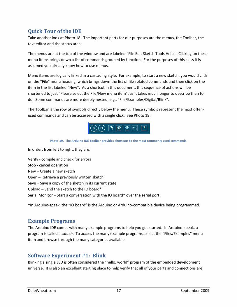
The Toolbar is the row of symbols directly below the menu. These symbols represent the most often-
used commands and can be accessed with a single click. See Photo 19.
Photo 19. The Arduino IDE Toolbar provides shortcuts to the most commonly used commands.
In order, from left to right, they are:
Verify - compile and check for errors
Stop - cancel operation
New – Create a new sketch
Open – Retrieve a previously written sketch
Save – Save a copy of the sketch in its current state
Upload – Send the sketch to the IO board*
Serial Monitor – Start a conversation with the IO board* over the serial port
*In Arduino-speak, the “IO board” is the Arduino or Arduino-compatible device being programmed.
Example Programs The Arduino IDE comes with many example programs to help you get started. In Arduino-speak, a
program is called a sketch. To access the many example programs, select the “Files/Examples” menu
item and browse through the many categories available.
Software Experiment #1: Blink Blinking a single LED is often considered the “hello, world” program of the embedded development
universe. It is also an excellent starting place to help verify that all of your parts and connections are
DaleWheat.com 18 September 2009
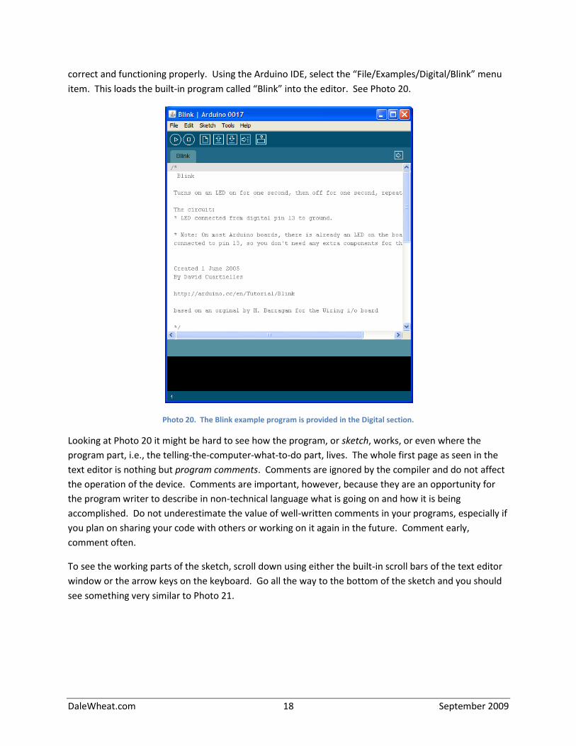
correct and functioning properly. Using the Arduino IDE, select the “File/Examples/Digital/Blink” menu
item. This loads the built-in program called “Blink” into the editor. See Photo 20.
Photo 20. The Blink example program is provided in the Digital section.
Looking at Photo 20 it might be hard to see how the program, or sketch, works, or even where the
program part, i.e., the telling-the-computer-what-to-do part, lives. The whole first page as seen in the
text editor is nothing but program comments. Comments are ignored by the compiler and do not affect
the operation of the device. Comments are important, however, because they are an opportunity for
the program writer to describe in non-technical language what is going on and how it is being
accomplished. Do not underestimate the value of well-written comments in your programs, especially if
you plan on sharing your code with others or working on it again in the future. Comment early,
comment often.
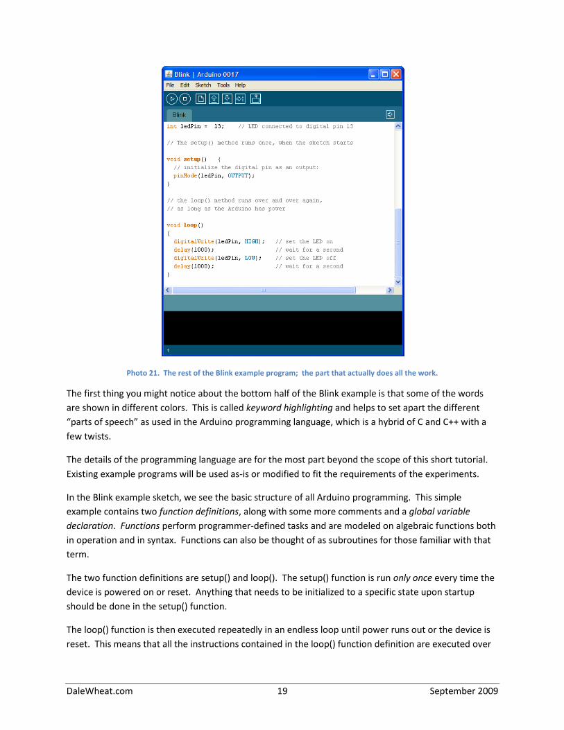
To see the working parts of the sketch, scroll down using either the built-in scroll bars of the text editor
window or the arrow keys on the keyboard. Go all the way to the bottom of the sketch and you should
see something very similar to Photo 21.
DaleWheat.com 19 September 2009
Photo 21. The rest of the Blink example program; the part that actually does all the work.
The first thing you might notice about the bottom half of the Blink example is that some of the words
are shown in different colors. This is called keyword highlighting and helps to set apart the different
“parts of speech” as used in the Arduino programming language, which is a hybrid of C and C++ with a
few twists.
The details of the programming language are for the most part beyond the scope of this short tutorial.
Existing example programs will be used as-is or modified to fit the requirements of the experiments.
In the Blink example sketch, we see the basic structure of all Arduino programming. This simple
example contains two function definitions, along with some more comments and a global variable
declaration. Functions perform programmer-defined tasks and are modeled on algebraic functions both
in operation and in syntax. Functions can also be thought of as subroutines for those familiar with that
term.
The two function definitions are setup() and loop(). The setup() function is run only once every time the
device is powered on or reset. Anything that needs to be initialized to a specific state upon startup
should be done in the setup() function.
The loop() function is then executed repeatedly in an endless loop until power runs out or the device is
reset. This means that all the instructions contained in the loop() function definition are executed over

DaleWheat.com 20 September 2009
and over again. Why this is useful should hopefully become apparent soon as we look at more
examples.
Notice that both the setup() and loop() functions call, i.e., execute other functions that are not defined
in the Blink example sketch. For example, in the setup() function, the pinMode() function is called with
two parameters, or values. The value of the ledPin variable identifies the input or output (I/O) pin of
interest and the OUTPUT predefined constant value indicates the desired mode. The pinMode()
function is defined in a library of commonly useful functions that are available to all Arduino sketches.
A list of available functions and other handy Arduino-specific information is available on the Arduino
web site at http://arduino.cc/en/Reference/HomePage or by selecting the “Help/Reference” menu item
from the Arduino IDE.
The pinMode() function must be called from the setup() function because, by default, all of the I/O pins
of the Atmel AVR ATmega328 (the Arduino’s brain chip) are configured as inputs when the chip first
starts. To use the pin to blink an LED, it has to be reconfigured as an output. The pinMode() function
takes care of that for us. It only has to be executed once and the pin stays in the output mode until
something else comes along and changes it. If nothing else ever changes it, it stays that way until the
chip loses power or is otherwise reset.
Now take a look at the loop() function. The first function called is digitalWrite(), which is passed the
parameters to identify the pin to write as well as the value to be written. The ledPin variable still
contains the number of the pin we want to blink (all pins are individually numbered for easy reference in
Arduino-Land). The predefined constant HIGH tells the function to write a digital value of 1, i.e., a digital
high level, to the pin. Since you wired up the user programmable LED to this pin in the previous section,
this will cause the LED to light.
Next a call is made to the delay() function. The parameter specifies the number of milliseconds, or
thousandths of a second to wait. Nothing useful happens during the waiting period; time passes and
that is all. Since 1,000 milliseconds were specified, one full second elapses and then the delay function
returns.
Another call to the digitalWrite() function occurs but this time the value to be written is LOW. This
writes a digital low level to the I/O pin, effectively turning off the LED. Another call to the delay()
function is made and the loop() function terminates.
The delay() function is required in this example because the ATmega328, operating at 16 MHz, can turn
the LED on and off many thousands of times a second, which we would perceive as being lit up as a
steady dot with about half the normal brightness. Since we want a human-perceptible blinking of the
LED, the delay() function slows things down enough for our eyes to tell what is happening.
Since the loop() function is called over and over again, the cycle repeats, ad infinitum. The LED blinks on
and off until the novelty wears off and we make it do something else.
DaleWheat.com 21 September 2009
Select the Correct Board The Arduino IDE needs to know which of the many Arduino variants is attached, as it currently has no
way to determine this information itself. Using the “Tools/Board” menu item, select the “Arduino
Duemilanove or Nano w/ ATmega328”, as those are functionally identical to the circuit you just built.
You MUST select the correct board before compiling the sketch. Different boards have different
memory capacities and this is handled automatically by the Arduino software once the correct board is
specified.
Compiling the Blink Example Sketch Let’s test out the Blink example exactly as it was delivered to us. Click on the “Verify” button in the
Toolbar. “Verify” is Arduino-speak for “compile”. It’s true that the process of compilation reveals errors
so there is a “verification” aspect to this action. You should see the message “Compiling…” displayed in
the status area at the bottom of the Arduino IDE. This can take several seconds to complete depending
on your computer’s resources. Once completed, you should see a “Done compiling.” status message
and the following message below that:
Binary sketch size: 896 bytes (of a 30720 byte maximum)
If not, please ask for assistance at this point. Something is not configured correctly.
Select the Correct Port The Arduino IDE is likewise unaware of which port to use to talk to your device. With your board
plugged in to the USB port of your computer, select the “Tools/Serial Port” menu item and select the
appropriate port from the available list. Your breadboarded Arduino MUST be plugged in and powered
on and working for the right port to be listed in the menu.
Uploading a Sketch Now it is time to send the Blink sketch down the wire from your computer to your device. This process
is called “uploading” in Arduino-speak. You may also hear people refer to this process as (device)
programming, writing, flashing or downloading. If all the above steps have been completed successfully,
click on the “Upload” Toolbar button. You should see the status message “Uploading to I/O Board…”
while the sketch is sent from the big computer to the little computer. This will take several seconds to
complete. During the upload process, the user programmable LED will blink sporadically. Once finished,
you should see the status message change to “Done uploading”. The LED should start to blink slowly on
and off: one second on, one second off, repeat.
If not, please doubled check that everything is connected properly and that the correct board and serial
port are selected within the Arduino IDE.
DaleWheat.com 22 September 2009
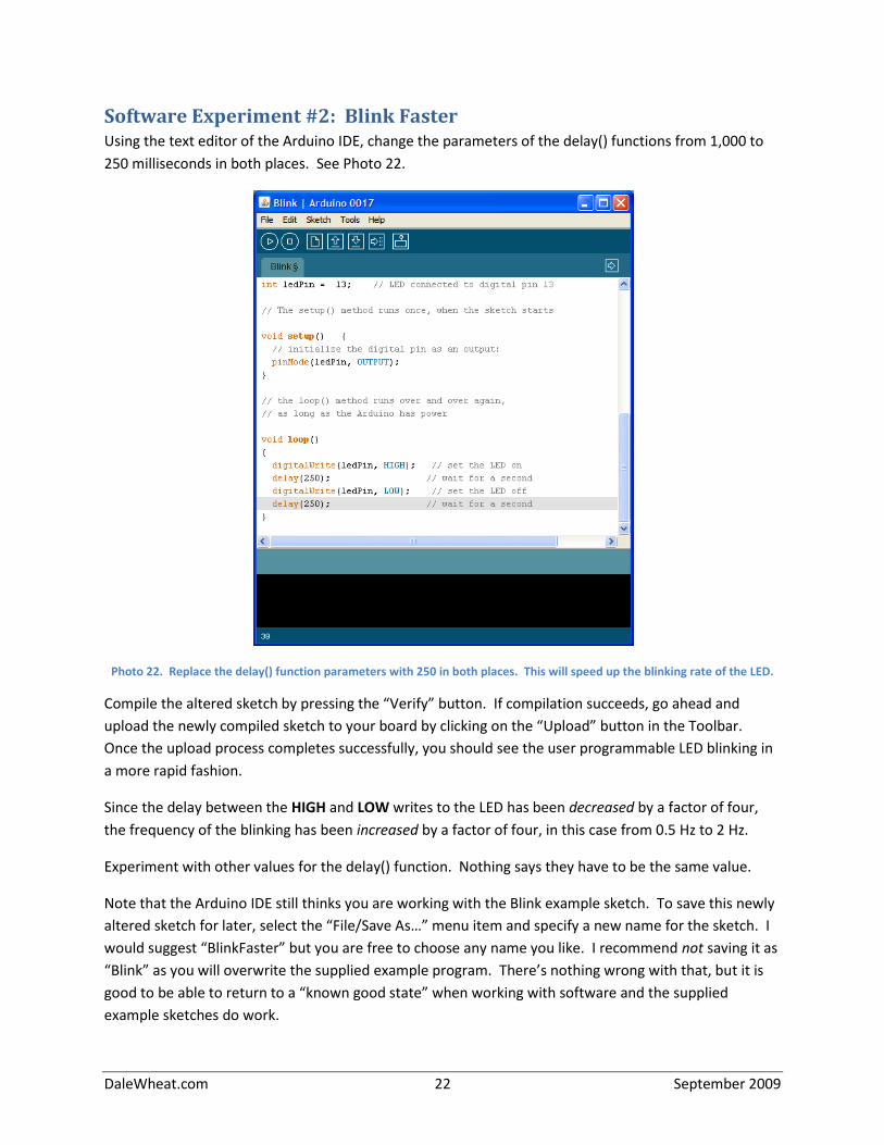
Software Experiment #2: Blink Faster Using the text editor of the Arduino IDE, change the parameters of the delay() functions from 1,000 to
250 milliseconds in both places. See Photo 22.
Photo 22. Replace the delay() function parameters with 250 in both places. This will speed up the blinking rate of the LED.
Compile the altered sketch by pressing the “Verify” button. If compilation succeeds, go ahead and
upload the newly compiled sketch to your board by clicking on the “Upload” button in the Toolbar.
Once the upload process completes successfully, you should see the user programmable LED blinking in
a more rapid fashion.
Since the delay between the HIGH and LOW writes to the LED has been decreased by a factor of four,
the frequency of the blinking has been increased by a factor of four, in this case from 0.5 Hz to 2 Hz.
Experiment with other values for the delay() function. Nothing says they have to be the same value.
Note that the Arduino IDE still thinks you are working with the Blink example sketch. To save this newly
altered sketch for later, select the “File/Save As…” menu item and specify a new name for the sketch. I
would suggest “BlinkFaster” but you are free to choose any name you like. I recommend not saving it as
“Blink” as you will overwrite the supplied example program. There’s nothing wrong with that, but it is
good to be able to return to a “known good state” when working with software and the supplied
example sketches do work.
DaleWheat.com 23 September 2009
Software Experiment #3: Blink Without Delay As mentioned previously in the discussion of the original Blink example sketch, the microcontroller
wastes time in the delay() function to provide a slow-enough or human-perceptible delay between
events, in this case the turning on and off of the LED, which otherwise would be an imperceptible blur.
This time is literally wasted, as no useful work is performed, nor can it be when using this technique.
An alternative to wasting this time is to use it to do some other task and then periodically check to see if
it is time to turn the LED on or off. This involves a little more work on the part of the programmer but
then enables the Arduino to appear to be doing more than one thing at a time.
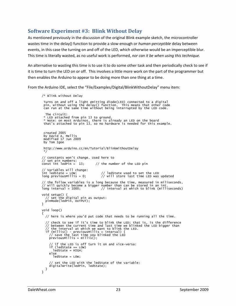
From the Arduino IDE, select the “File/Examples/Digital/BlinkWithoutDelay” menu item:
/* Blink without Delay Turns on and off a light emitting diode(LED) connected to a digital pin, without using the delay() function. This means that other code can run at the same time without being interrupted by the LED code. The circuit: * LED attached from pin 13 to ground. * Note: on most Arduinos, there is already an LED on the board that's attached to pin 13, so no hardware is needed for this example. created 2005 by David A. Mellis modified 17 Jun 2009 by Tom Igoe http://www.arduino.cc/en/Tutorial/BlinkWithoutDelay */ // constants won't change. Used here to // set pin numbers: const int ledPin = 13; // the number of the LED pin // Variables will change: int ledState = LOW; // ledState used to set the LED long previousMillis = 0; // will store last time LED was updated // the follow variables is a long because the time, measured in miliseconds, // will quickly become a bigger number than can be stored in an int. long interval = 1000; // interval at which to blink (milliseconds) void setup() { // set the digital pin as output: pinMode(ledPin, OUTPUT); } void loop() { // here is where you'd put code that needs to be running all the time. // check to see if it's time to blink the LED; that is, is the difference // between the current time and last time we blinked the LED bigger than // the interval at which we want to blink the LED. if (millis() - previousMillis > interval) { // save the last time you blinked the LED previousMillis = millis(); // if the LED is off turn it on and vice-versa: if (ledState == LOW) ledState = HIGH; else ledState = LOW; // set the LED with the ledState of the variable: digitalWrite(ledPin, ledState); } }
DaleWheat.com 24 September 2009
Software Experiment #4: Button This software experiment requires the addition of some extra hardware to the circuit. Look in the small
parts bag and find the other push button. You installed the first push button as part of the reset
circuitry when originally building your circuit. You also need another beige resistor and the short orange
jumper wire.
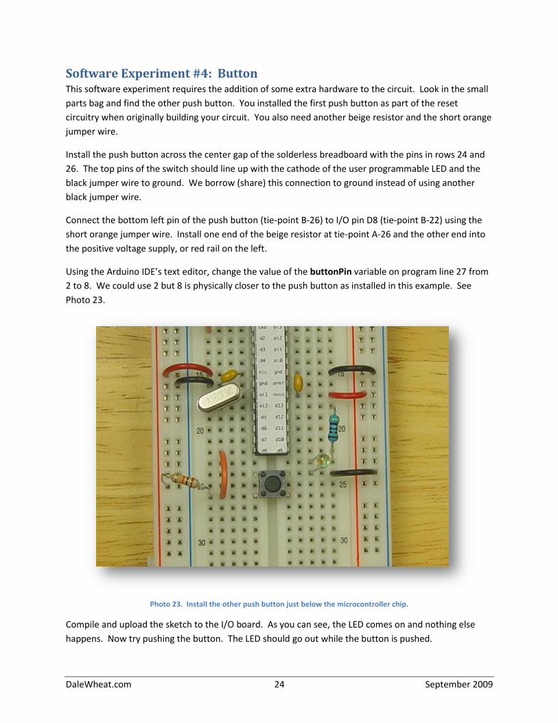
Install the push button across the center gap of the solderless breadboard with the pins in rows 24 and
26. The top pins of the switch should line up with the cathode of the user programmable LED and the
black jumper wire to ground. We borrow (share) this connection to ground instead of using another
black jumper wire.
Connect the bottom left pin of the push button (tie-point B-26) to I/O pin D8 (tie-point B-22) using the
short orange jumper wire. Install one end of the beige resistor at tie-point A-26 and the other end into
the positive voltage supply, or red rail on the left.
Using the Arduino IDE’s text editor, change the value of the buttonPin variable on program line 27 from
2 to 8. We could use 2 but 8 is physically closer to the push button as installed in this example. See
Photo 23.
Photo 23. Install the other push button just below the microcontroller chip.
Compile and upload the sketch to the I/O board. As you can see, the LED comes on and nothing else
happens. Now try pushing the button. The LED should go out while the button is pushed.
DaleWheat.com 25 September 2009
Software Experiment #4a: Not Button On program line 46, change the double equal signs (“==”) to an exclamation point and a single equal
sign, with no intervening spaces (“!=”). This changes the program meaning from “is equal to” to “is not
equal to” in the evaluation section of the sketch. Those just happen to be the symbols used by the C
programming language to represent those operators. Recompile the sketch and upload it. Now the LED
stays off until the push button is pushed. It stays lit as long as the button remains pressed.
Being able to change the logic of a program gives you a lot of versatility in designing user interface
circuits and other applications. You could also require the button to be pressed for a certain length of
time before starting some process. There are a lot of possible variations.
Software Experiment #4b: Eliminating the External Pull Up Resistor The beige resistor in this circuit acts as a pullup resistor. The push button either connects the
microcontroller input to ground (when pressed) or to nothing at all (when released). In the released
state, there is nothing connected in the circuit to influence the voltage at that point, other than stray
interference from radio waves in the air. With the addition of the pullup resistor, the voltage present at
the input to the microcontroller pin is always at a known high state until the push button is pressed, at
which time the voltage drops to nearly zero. The relatively high resistance of the pullup resistor only
permits a very small amount of current to flow through the circuit.
Remove the beige pullup resistor from the circuit and observe the resulting behavior. Sometimes it will
work and sometimes it won’t. Reinstall the resistor to confirm that it works properly again.
An alternative to using the external pullup resistor is to enable the pullup resistor that is present on
every input of the microcontroller chip. This is done by writing a digital high value to the pin even
though it is configured as an input. Add this line to the setup() function:
digitalWrite(buttonPin, HIGH);
Recompile the program and upload it to the board. Remove the beige pullup resistor from the circuit
and confirm that it is working properly, even with the pullup missing from the circuit.
DaleWheat.com 26 September 2009
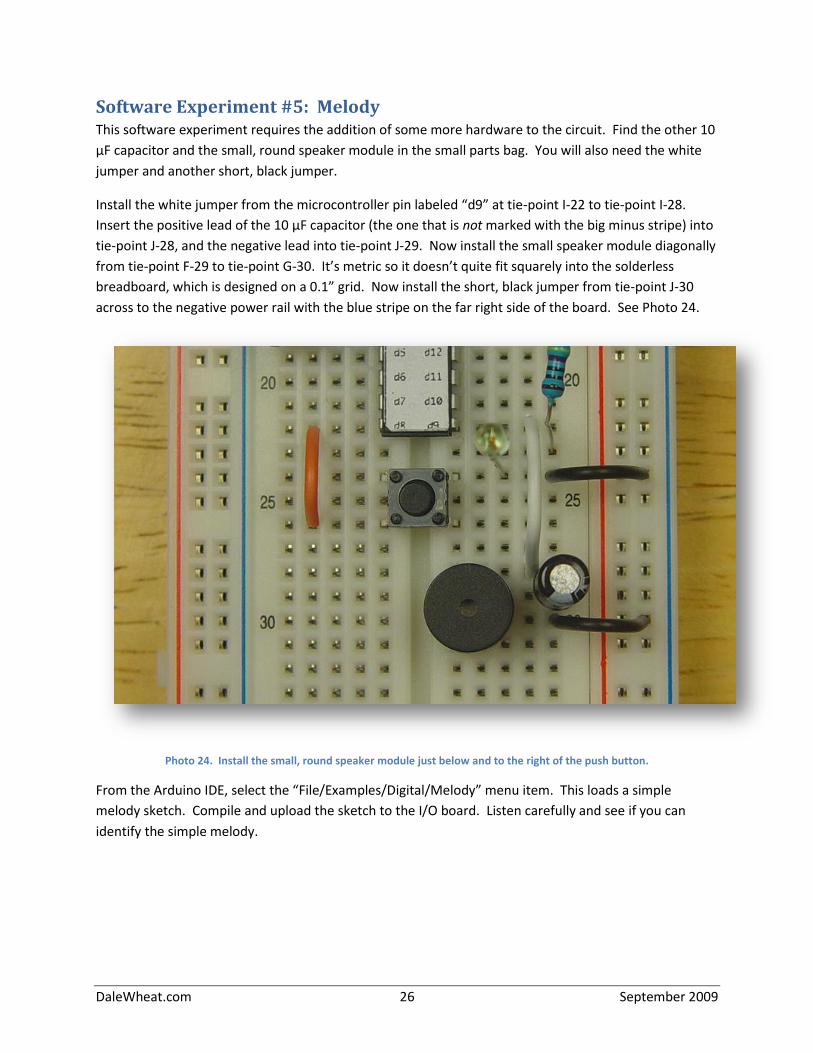
Software Experiment #5: Melody This software experiment requires the addition of some more hardware to the circuit. Find the other 10
μF capacitor and the small, round speaker module in the small parts bag. You will also need the white
jumper and another short, black jumper.
Install the white jumper from the microcontroller pin labeled “d9” at tie-point I-22 to tie-point I-28.
Insert the positive lead of the 10 μF capacitor (the one that is not marked with the big minus stripe) into
tie-point J-28, and the negative lead into tie-point J-29. Now install the small speaker module diagonally
from tie-point F-29 to tie-point G-30. It’s metric so it doesn’t quite fit squarely into the solderless
breadboard, which is designed on a 0.1” grid. Now install the short, black jumper from tie-point J-30
across to the negative power rail with the blue stripe on the far right side of the board. See Photo 24.
Photo 24. Install the small, round speaker module just below and to the right of the push button.
From the Arduino IDE, select the “File/Examples/Digital/Melody” menu item. This loads a simple
melody sketch. Compile and upload the sketch to the I/O board. Listen carefully and see if you can
identify the simple melody.
DaleWheat.com 27 September 2009
Software Experiment #6: Text to Song Conversion Just for fun, copy the file “speech_daisybell.pde” (supplied by your instructor) to your Arduino IDE
installation folder. From the Arduino IDE, select the “File/Open” menu item and select the file
“speech_daisybell”. It may complain that it needs to be in its own folder but will offer to fix the problem
for you. Allow it to do so and it will correctly load the sketch. Compile and upload to your I/O board.
You will need to move the white wire from D9 to D11 as this is the output used by the sketch.
Now listen very carefully. You should hear a decidedly artificial voice singing a song. It’s not perfect by
any means but it shows what can be done with some clever programming.
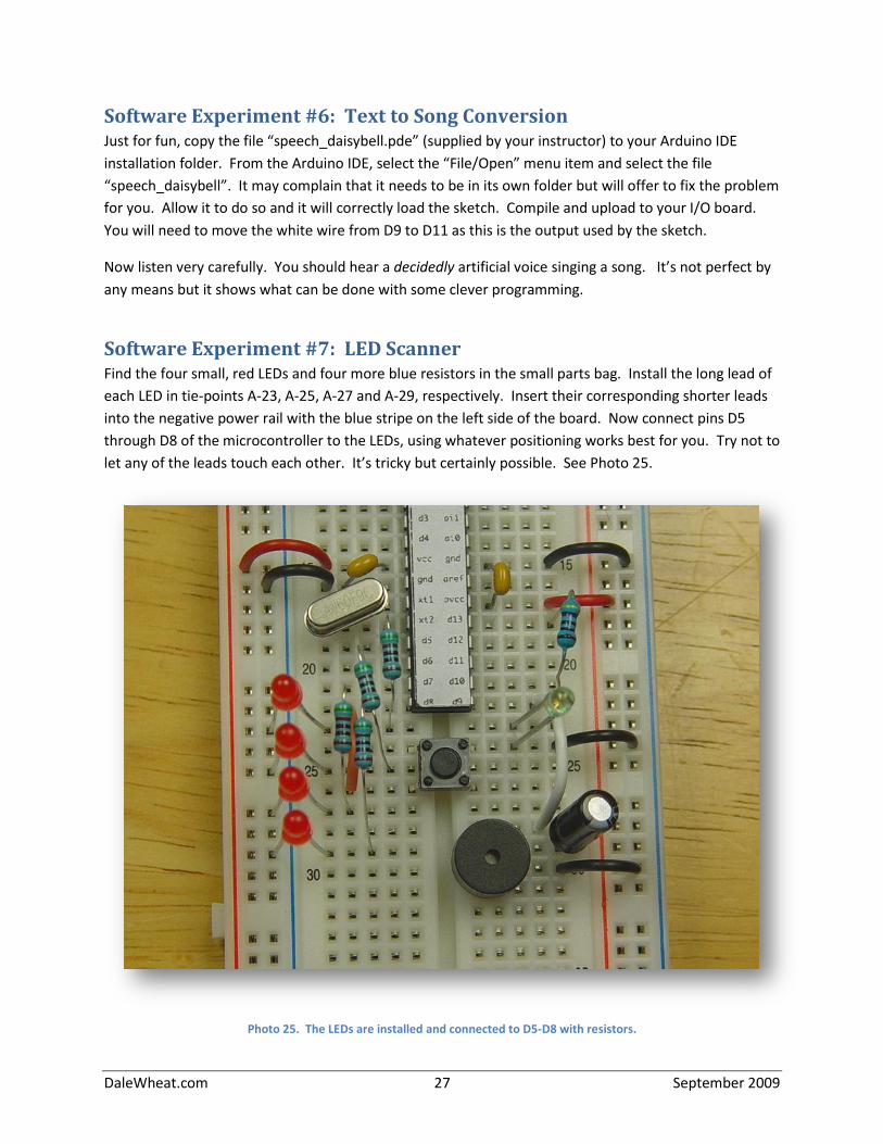
Software Experiment #7: LED Scanner Find the four small, red LEDs and four more blue resistors in the small parts bag. Install the long lead of
each LED in tie-points A-23, A-25, A-27 and A-29, respectively. Insert their corresponding shorter leads
into the negative power rail with the blue stripe on the left side of the board. Now connect pins D5
through D8 of the microcontroller to the LEDs, using whatever positioning works best for you. Try not to
let any of the leads touch each other. It’s tricky but certainly possible. See Photo 25.
Photo 25. The LEDs are installed and connected to D5-D8 with resistors.
DaleWheat.com 28 September 2009
From the Arduino IDE, select the “File/Examples/Control/ForLoopIteration” menu item. This loads one
of the sample sketches that illustrates a very useful control structure called a for loop. A for loop
executes a statement or group of statements a certain number of times, determined by the way the
loop is written.
Some small changes will need to be made to the code in the example sketch for it to match our
hardware. Change the numbers in line 22 and line 29 to look like this:
for (int thisPin = 5; thisPin < 9; thisPin++) {
Change the numbers in line 38 to look like this:
for (int thisPin = 7; thisPin >= 6; thisPin--) {
Compile the sketch and upload it to your I/O board. The LEDs should light up one at a time in an
animated pattern. Remind you of anything, hmmm?
Software Experiment #8: Hello, world! For this software experiment, no additional hardware is required.
From the Arduino IDE, select the “File/Examples/Stubs/HelloWorld” menu item. This loads the “stub” or
skeletal version of the classic “Hello, World!” program that is used as an introduction to many
programming languages. Notice that it lacks any sort of programmer comments and only contains the
bare minimum of code needed to get the job done.
Compile the sketch and upload. It will appear that nothing is happening but that is not the case. Plenty
of activity is going on but you are not yet able to perceive it. Now click on the “Serial Monitor” button
on the Toolbar. Starting with version 0017 of the Arduino IDE, this opens a new window for
communicating with the serial port. Previous versions displayed the serial terminal in the main window.
At first you may only see random garbage characters displayed in the window. This is most likely
because of a serial port baud rate mismatch. Look in the lower right corner of the serial monitor
window and you will find an unlabeled drop-down control that contains various baud rates that are
supported by the serial monitor. Select “9600” and the monitor should soon start showing multiple
lines of “Hello World!” Remember that the loop() function is called repeatedly in Arduino programs.
Note that the baud rate is specified within the sketch in the setup() function. The parameter passed to
the Serial.begin() function is the requested baud rate. Try changing this baud rate to 300 (a very slow
baud rate) and recompiling and uploading the modified sketch to your I/O board. Launch the serial
monitor if it is not already visible and adjust the baud rate there to 300 as well. Give it a second or two
to synchronize. Once everyone is in step, you should see the phrase “Hello World!” printed at a leisurely
pace.
You can also use the serial port to talk back to the Arduino but that is a story for another time.