houdini (tm) -ii remotely operated vehicle systeminfohouse.p2ric.org/ref/13/12771.pdf · houdini-i...
TRANSCRIPT
DOE/EM-0495
Houdini TM-IIRemotely Operated Vehicle
System
Industry Programs andRobotics Crosscutting Program
Prepared forU.S. Department of Energy
Office of Environmental ManagementOffice of Science and Technology
December 1999
Houdini TM-IIRemotely Operated Vehicle
System
OST/TMS ID 2085(Houdini: OST/TM ID 98)
Industry Programs andRobotics Crosscutting Program
Demonstrated atGunite and Associated Tanks Operable Unit
Oak Ridge National LaboratoryOak Ridge, Tennessee

iii
Purpose of this document
Innovative Technology Summary Reports are designed to provide potential users with theinformation they need to quickly determine whether a technology would apply to a particularenvironmental management problem. They are also designed for readers who may recommendthat a technology be considered by prospective users.
Each report describes a technology, system, or process that has been developed and tested withfunding from DOE’s Office of Science and Technology (OST). A report presents the full range ofproblems that a technology, system, or process will address and its advantages to the DOEcleanup in terms of system performance, cost, and cleanup effectiveness. Most reports includecomparisons to baseline technologies as well as other competing technologies. Informationabout commercial availability and technology readiness for implementation is also included.Innovative Technology Summary Reports are intended to provide summary information.References for more detailed information are provided in an appendix.
Efforts have been made to provide key data describing the performance, cost, and regulatoryacceptance of the technology. If this information was not available at the time of publication, theomission is noted.
All published Innovative Technology Summary Reports are available on the OST Web site athttp://ost.em.doe.gov under “Publications.”
iv
TABLE OF CONTENTS
1. SUMMARY page 1
2. TECHNOLOGY DESCRIPTION page 5
3. PERFORMANCE page 9
4. TECHNOLOGY APPLICABILITY AND ALTERNATIVES page 17
5. COST page 19
6. REGULATORY AND POLICY ISSUES page 23
7. LESSONS LEARNED page 25
APPENDICES
A. REFERENCES page 29
B. COST MODEL page 30
C. ACRONYMS AND ABBREVIATIONS page 33

U.S. Department of Energy 1
SECTION 1
Technology Summary
ProblemThe U.S. Department of Energy (DOE) is responsible for cleaning up and closing 273 large, aging,underground tanks it has used to store tens of millions of gallons of high- and low-level radioactive andmixed waste. The waste’s radioactivity precludes humans from working in the tanks. Therefore, a remote-controlled retrieval method must be used. The Houdini robot (as pictured in Fig. 1) addresses the need forvehicle-based, rugged, remote manipulation systems that can perform waste retrieval, characterization, andinspection tasks. The DOE Office of Science and Technology (OST) funded development of the originalHoudini system as described in the Innovative Technology Summary Report (ITSR) listed in Reference 1. Lessons learned during the field deployment of this unit were later incorporated into the redesign andfabrication of a second-generation system known as the Houdini-II. This report provides an update to theprevious Houdini ITSR and covers the performance of both generations of the Houdini Remotely OperatedVehicle System through September 1999.
Houdini folds up for entry through 24-in. risers(as pictured in Fig. 2), which are openings in thetanks’ ceilings. After its entry, Houdini unfolds forwork. Houdini allows work to be performed thatwould otherwise be difficult if not impossible toaccomplish because of confined spaces andradiological and hazardous environments.
While several bulk waste retrieval techniques areavailable, Houdini offers a unique solution forremoving the remnant “heel” material left behindafter sluicing. The system has also proveneffective at removing discarded nonpumpableobjects and in-tank hardware. The need for thistechnology is immediate because standardsluicing has already been attempted at someDOE sites. Mixing systems offer anaternativebut with limited effectiveness forwaste heels. Another lternative—manned entry
to these confined and hazardous paces—would be costly and impractical.
How it worksHoudini is a remotely controlled, folding, work platform that can pass through24-in. openings called risers and then expand to become a 4 x 5-ft minibulldozer, complete with a plow blade; a dextrous, high-payload manipulator;and remote camera systems. A single-operator control console can be locatedup to a few hundred feet away. Though training is straightforward with nospecial qualifications needed, inexperienced operators can easily damage thesystem; therefore, the need for operators to practice in cold tests is critical tomission success.
Houdini can deploy a variety of tools fitted with appropriate grasp points andcan manipulate objects up to 250 lb. It can shovel waste or deploy localizedsluicing systems for heel removal, cut and remove in-tank debris, deploy
SUMMARY
Fig. 1. Houdini unfolded for work.
Fig. 2. Houdinifolded for entrythrough risers.
2 U.S. Department of Energy
tools to obtain core samples, and perform characterization and inspection missions. It has successfully andextensively manipulated a localized sluicer that uses high-pressure water to dislodge and then pump avariety of physical waste forms.
Houdini is lowered from an enclosed and shielded deployment package, which houses the tether reel andthe robot for stowage and maintenance. Power to control and hoist Houdini’s in-tank remote hardware isprovided by an external unit. Hydraulic fluid and electrical power pass to Houdini through a customizedtether.
If there is a loss of power, the system has a fail-safe feature that allows the robot chassis to collapse undergravity so that it can then be extracted from the tank. The system is designed for full submersion inradiological and hazardous environments although the tethers on both Houdini-I and Houdini-II haveexperienced some in-leakage. Attempts are still being made to correct this problem. Houdini’s primarylimitations are that it can reach only about 6 ft up tank walls, its capability to travel over or through deepwaste is currently uncertain, and it requires frequent maintenance.
Potential marketsHoudini is designed primarily for radioactive waste retrieval in underground storage tanks and has directapplicability to a number of sites in the DOE complex, including Oak Ridge National Laboratory (ORNL),Fernald, Hanford, the Idaho National Engineering and Environmental Laboratory (INEEL), and theSavannah River Site (SRS).
Houdini-IThe Houdini-I, was demonstrated and operated at the Gunite and Associated Tanks (GAAT) Operable Unit(OU) at ORNL from June 1997 until August 1998. A Houdini-II unit was built in 1998 to take advantage oflessons learned in early system usage. Upon completion of cold testing, this system was deployed for thefirst time at GAAT on January 28, 1999. Houdini is manufactured by RedZone Robotics, Inc., a smallbusiness in Pittsburgh, Pennsylvania.
Houdini-I was designed under a Research Opportunity Announcement from the Industry Programs at theFederal Energy Technology Center (FETC) in Morgantown, West Virginia. Research staff at CarnegieMellon University’s Robotics Institute first proposed the concept of a folding robotic work platform in 1992for use at Fernald. Carnegie Mellon researchers collaborated with RedZone during the early design stagesof the Houdini-I project.
The final product reflects significant input, from conception to completion, of DOE’s Office of EnvironmentalRestoration (EM-40) remediation contractors at both ORNL and Fernald. System requirements werederived from technical needs for remediation of K-65 silos at Fernald’s OU4, although the unit wassubsequently redirected to ORNL, with some minor modifications, to meet schedule requirements for thegunite tanks project. DOE field office counterparts at those sites have endorsed and supported the project,along with two OST (EM-50) organizations—the Robotics Crosscut Program (RBX) and the Tanks FocusArea (TFA).
Commercial availabilityHoudini is manufactured by RedZone Robotics, and its development has been fostered by a multiple siteand multiple program team funded by OST. Based upon lessons learned during the demonstration of thevehicle system at ORNL’s North Tank Farm (NTF), RedZone overhauled the design of Houdini-I. During thesummer of 1998, Houdini-II was delivered to ORNL for demonstration and deployment at the South TankFarm (STF).
Demonstration Summary
This report covers Houdini-I and Houdini-II project activities from the inception in fiscal year (FY) 1995 toSeptember 1999.

U.S. Department of Energy 3
GAAT demonstration at ORNLThe GAAT OU contains 16 tanks of varying size, a majority of which are in two areas—the NTF and theSTF. Constructed during the 1940s and 1950s, the 12 underground tanks are made of a specialized type ofconcrete, gunite, and are 20, 25, or 50 ft in diameter and 12 ft deep with few access ports. None of theaccess ports are larger in diameter than 30 in. The tanks have been taken out of service due to their ageand uncertain condition.
The bulk of the waste was removed during the 1980s using standard hydraulic sluicing techniques.However, a waste "heel" remains to be removed, along with objects left in the tanks after previouscampaigns. The heel consists of sludge of varying consistency, with depths of up to 3 ft and radiation levelsup to 200 R/hr. Each tank also has supernatant water above the sludge at depths ranging from inches toseveral feet.
Because of the NTF’s location in the heart of the ORNL complex, aggressive targets were set for removingwaste from NTF tanks as part of the GAAT Treatability Study. NTF tanks had lower radioactivity levels thanthose in the STF, and there was no sluicing of those tanks in the 1980s. After successful operations in theless hostile NTF tanks, the equipment was relocated to the STF to initiate the GAAT Remediation Project.
Demonstration statusHoudini-I was delivered to ORNL in September 1996, deployed in a cold-test facility in November, and firstdeployed in GAAT in June 1997. The unit played a critical role in the cleanup of three gunite tanks, W-3, W-4 and W-6, before it was retired from service following the delivery of the Houdini-II system. Whileoperating, Houdini-I proved rugged, capable of waste retrieval, and able to withstand high reaction forceoperations such as wall core sampling. The unit was even able to operate while hanging, which was thecase when Houdini-I was used to cut and remove cables and steel pipes hanging below manways in TanksW-3 and W-4.
Houdini-II was delivered to ORNL in September 1998. After completing some open fabrication items andreworking the system containment structure, the unit underwent several weeks of cold testing before itsdelivery to the tank farm in January 1999. The vehicle was deployed into tank W-7 for the first time onJanuary 28, 1999, and continued to plow, remove debris, and take core samples of the tank walls untilMarch 13, 1999.
Both the Houdini-I and Houdini-II vehicle systems have played key roles in the full suite of remotetechnologies that has been put to the test at GAAT and that has been found to work well together. Eachtechnology has made unique and important contributions to overall mission success. Houdini has interfacedwith other retrieval equipment developed by TFA, such as the mini sluicer and the Modified Light Duty UtilityArm (MLDUA), a programmable long-reach robot arm.
Advantages over baselineThe advantages of both Houdini systems over the baseline technology of manned entry are self-evident,but they were not specifically measured. It would be too dangerous, impractical, and costly to send workersinto the tanks just to compare approaches. A cost model in Sect. 5, however, calculates a possible paybackof better than 10 to 1 for OST’s investment in this technology—through the use of Houdini-I at the ORNLGAAT OU alone. The basis of the calculation is the dollar value of avoided radiation exposure. The modelis presented with disclaimers as to its absolute accuracy.
Regulatory concernsRegulatory issues are limited to the selection of the type of hydraulic fluid for the system. Under manycircumstances, petroleum-based fluids normally used are unacceptable because of their potential to affectwaste classification if sufficient quantities leaked into the tank. Fortunately, several water- and mineral-oil-based products are available and have been used in these systems as alternative working fluids.
4 U.S. Department of Energy
Houdini limitationsAs could be expected from most first-generation systems, Houdini-I demonstrated a number of deficienciesand areas for improvement during the GAAT deployment:• Maintenance was much more difficult and more frequently required than desirable.• The vehicle was not always centered over the riser.• The robot stowage compartment was too small, making system deployment and retrieval difficult for
the operators and occasionally hazardous to the equipment.
Based upon the lessons learned from the first unit at ORNL, Houdini’s design was completely overhauledand a second generation system, Houdini-II, was built with funds from the OST RBX. This second unit wasintended to offer improved system modularity, reliability, durability, and maintainability. As in-tank timeaccrued on the system, it became apparent that while many design issues had been resolved, reliability andmaintainability still have much room for improvement (see Sect. 5 “Lessons Learned”). Additional Houdiniunits are obtainable from RedZone Robotics.
Contacts
Technical informationBarry Burks, The Providence Group, (423) 927-5519, [email protected] Slifko, RedZone Robotics, (412) 765-3064, [email protected]
OST contactsLinton Yarbrough, DOE (Albuquerque), (505) 845-6569, [email protected] Kothari, DOE (FETC), (304) 285-4579, [email protected] De Gregory, DOE (Headquarters), (301) 903-7949, [email protected]
GAAT project contactsCavanaugh Mims, DOE (Oak Ridge), (423) 576-9481, [email protected] Noble-Dial, DOE (Oak Ridge), (423) 241-6184, [email protected] Van Hoesen, ORNL, (423) 574-7264,David Vesco, The Providence Group, (423) 927-5519,
Licensing informationThis system is available for purchase from RedZone Robotics. Inc.
OtherAll published Innovative Technology Summary Reports are available on the OST Web site at http://em-50.em.doe.gov under “Publications.” The Technology Management System, also available through theOST Web site, provides information about OST programs, technologies, and problems. The OST referencenumber for Houdini-I is 98; the number for Houdini-II is 2085.
U.S. Department of Energy 5
SECTION 2
Overall Process Definition
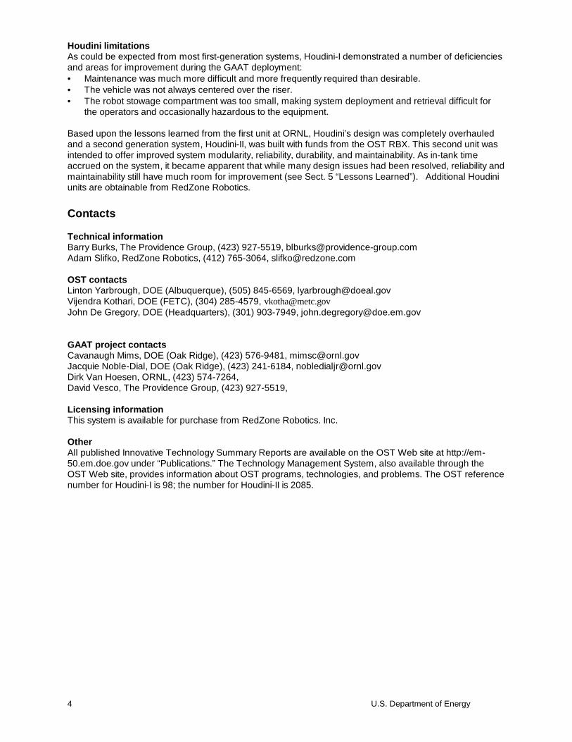
ComponentsHoudini consists of five main components: thevehicle, tether, tether management anddeployment system (TMADS), power distributionand control unit (PDCU), and the control console.Fig. 3 is a conceptual drawing of the Houdinisystem, which shows some of the tools that canbe deployed. A “suitcase” controller or button boxfacilitates maintenance in case of controls failureand may also be used to bring the system on-linequickly in the field.
The centerpiece and workhorse of the Houdinisystem is the vehicle. With a 22.5-in-diameterprofile when folded, it is designed to pass throughopenings as small as 24 in. Once deployed, itunfolds to provide a powerful work platform with asubstantial footprint. Given sufficient surfacefriction, the vehicle can turn in place, climb a 35°ramp and remain stable on slopes up to 45°.
ApplicationsHoudini was developed to provide mobile waste retrieval capability for remediating radioactive wastestorage tanks across the DOE complex, with specific emphasis on ORNL and Fernald requirements.Rugged design and sturdy construction make it well suited for heavy work and waste mobilization.
Houdini can withstand high-pressure-water decontamination. It is designed to be relocated between tankrisers and can be deployed in enclosed spaces, such as theequipment rooms proposed for Fernald silos remediation, as well asfully exposed to the elements as is the case on the open equipmentplatforms erected for the ORNL GAAT project. References 2, 3, and4 in Section 8 give design details for interested readers.
Figures 4 through 9 illustrate a few of the many waste retrieval andtool deployment tasks that Houdini can successfully perform. Thesystem has been designed to be outfitted optionally with the Positionand Orientation Tracking System (POTS)—an ORNL-developed,OST-funded sensor technology that can precisely report vehicleposition within the tank. With the exception of expendable cameraelements, Houdini is designed to operate in radiation fields of up to
TECHNOLOGY DESCRIPTION
Fig. 3. Houdini system elements.
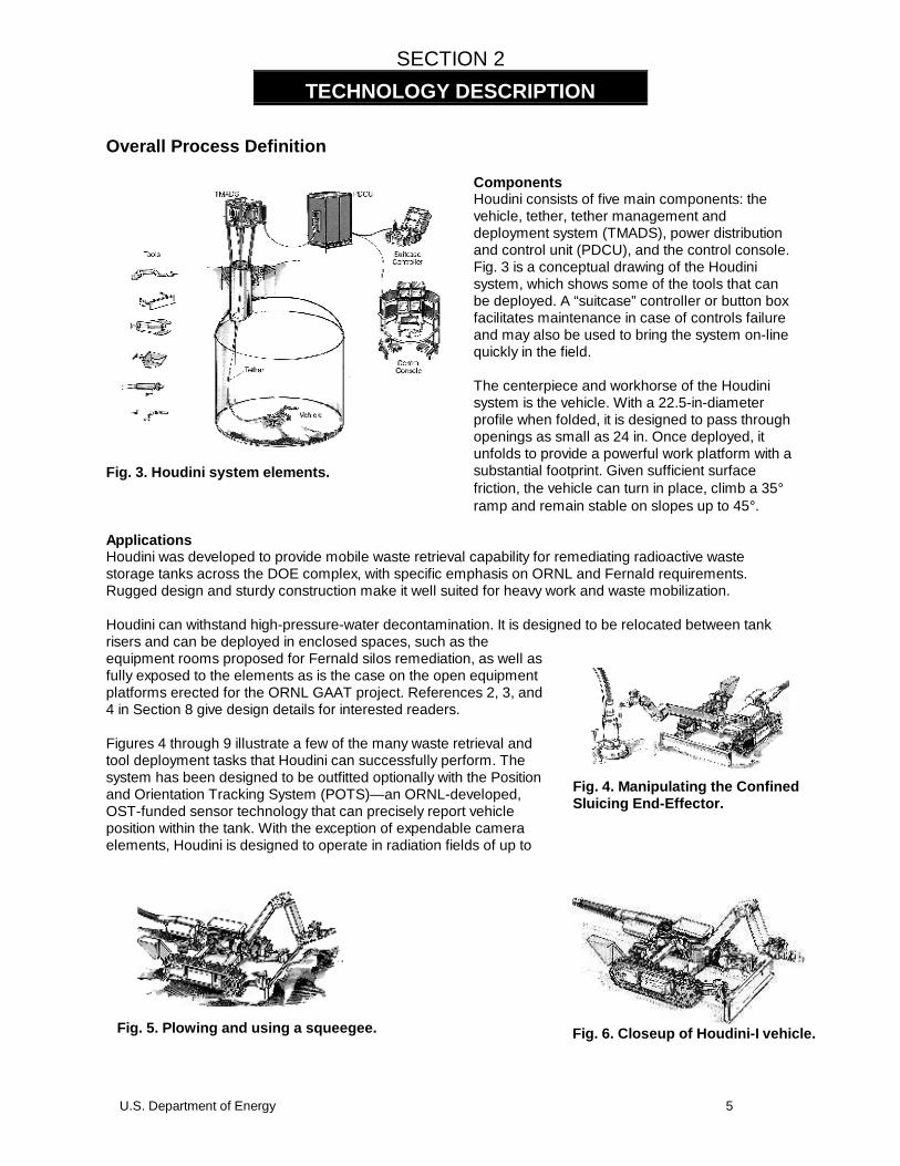
Fig. 4. Manipulating the ConfinedSluicing End-Effector.
Fig. 5. Plowing and using a squeegee. Fig. 6. Closeup of Houdini-I vehicle.

6 U.S. Department of Energy
100 R/hr with cumulative exposures of up to 105 R.
Houdini vehicle detailsThe 1,000-lb vehicle is teleoperated, which means it iscontrolled directly by an operator in a remote location with nopreprogrammed routines. It is also skid-steered; that is, itsspeed and direction are controlled by the relative position oftwo joysticks or, if selected, foot pedals, each of whichcorresponds to one tread’s motion. The treads arecommercially available and easily replaced. Maximum speedis 1 ft/s.
Four vehicle-frame members form a parallelogram that isopened by a hydraulic cylinder pushing across diagonalcorners. Should power be lost and the robot requires
extraction, the plow, frame, and manipulator collapse under gravity for easy removal from the tank.
The manipulator is a Schilling Titan-III, which is controlled from the console by the master arm, a smallmultilink input device with the same kinematics as the in-tank slave arm. The arm can lift 250 lb (113 kg) ata full reach of 76 in. (1.9 m). The plow blade has a squeegee attached and can be raised or lowered.
Two cameras and a microphone are provided to give operators a telepresence in the tank. One camera isdirectly fixed to the wrist of the robot arm, and the other is mounted on a pan and tilt module on the rear ofthe vehicle. A system feature allows fouled camera lenses tobe cleaned with a shot of water followed by a burst of airsprayed through installed nozzles.
The nearly 3-in-diam tether terminates at the rear of thevehicle. The tether is pivoted to reduce reaction forces. Acounterweight is provided to assist in heavy manipulation andlocomotion. On Houdini-I, the controller for the robot arm ismounted in this area; on Houdini-II, the controller has beenmoved into the tether reel in the TMADS.
The tether is the vehicle’s lifeline. It provides hydraulic fluid,electrical power, signal lines, and a small water circuit forcamera cleaning. The tether is rated at 10,000-lb strength,ensuring that the machine will not get stuck inside the tank.
The tether is payed out from the TMADS, which also serves as the interface for the robot between the in-tank and external environments. Both the Houdini-I and Houdini-II TMADS structures are shielded andenclosed with sealed doors that lead to the tank riser. Glove ports, a spray wand, and access features areprovided for maintenance and decontamination. On Houdini-II, one steel sidepanel is hinged and can be
opened for vehicle removal.
Fig. 7. Cutting/shearing.
Fig. 8. Non-pumpable ob ject removal.
Fig. 9. Scooping waste.

U.S. Department of Energy 7
Support systemsAt the PDCU, the switchgear, programmable controls, and hydraulic power supply are situated well awayfrom the radiological exclusion zone. Tether lines from the vehicle to the TMADS pass from the rotatingtether reel to fixed bulkhead connections, using slip rings and rotary hydraulic unions. Electric, water, andcompressed air utility feeds are made at the PDCU. Commands are sent to the controller in the PDCU fromthe operator control station.
The TMADS provides a convenient docking area for the robot, allowing operators to remotely manage andstore the vehicle and tether. Sealed and shielded, it simplifies installing and relocating the system tomultiple tanks in a waste retrieval campaign. Lexan panels, glove ports, and pass-through ports on theTMADS allow many maintenance activities to be performed on the system without breaking containment.
A spray wand is provided for removal of residual waste. Additional structural elements include acontainment bezel that provides extra height to the containment structure for storage and maintenance, butcan be removed for applications at other sites where headspace is limited; a riser interface that mates thecontainment bezel to the decontamination spray ring; and a TMADS stand, which is a steel structure forsupport against potentially high winds. The decontamination spray ring and riser sleeve then lead the rest ofthe way into the tank.
Installation and deploymentThe TMADS is where the generically capable Houdini system meets the specific physical limitations fordeployment at a particular location. At ORNL, the TMADS is hoisted onto its stand on the GAAT projectbridge structure. The TMADS can also be suspended overhead or laid on its side if some other applicationwarrants. Sitting directly over a riser is the riser interface, a simple, spool-like piece that mates to thecontainment bezel, which is attached to the TMADS.
To deploy Houdini-I, the TMADS door is opened, the manipulator is uncurled, and the folded robot is slowlylowered into the tank. For Houdini-II, there is no need to uncurl the manipulator. In either case, once thevehicle reaches an open area, the frame unfolds, in mid-air and the vehicle is then lowered to the tank floor.
The manipulator is configured so that the elbow touches down first, allowing the vehicle to pivot around theelbow and plow until the tracks touch, at which point they are driven slowly forward so that the vehicle landsin the right orientation. Video from cameras in the TMADS, mounted in the tank and on the robot, helpguide the operators.
Once landed, Houdini can then start its mission of plowing and object retrieval. During operation, the tetheris payed out by the operator as needed as the vehicle is driven around in the tank.
For Houdini-I, a large port on the containment bezel below the TMADS allows the passage of tools,nonpumpables, and other objects in and out of the tank using vinyl bags. Similar items are transferredthrough a pass-through port mounted in a sidewall on the Houdini-II TMADS. Tools with T-Handles can belowered down and then grabbed and operated.
Some operations are possible with the robot arm while Houdini is hanging by its tether. For instance, pipesand cables were cut from around two risers at ORNL while Houdini was suspended. However, the unittended to sway, so good operator skills were required.
System retrieval is basically the reverse of deployment, with the additional step of aligning the plow andmanipulator before folding the vehicle. Waste on the treads and vehicle is washed off in a high-pressurewater spray ring below the riser interface. Once the vehicle has been retracted into TMADS, a spray wandattached to a pressure washer may be used for further decontamination, if necessary.
System Operation
The Houdini console consists of two joysticks to control vehicle motion, a manipulator master controller,video displayed from two on-board cameras and up to six off-board cameras, as well as status displays,and other controls (see Fig. 10). The system can be run by a single operator. Foot pedals can be providedto override and replace joystick control of vehicle motion. Access to the programmable controller that runsthe overall system is possible with an additional personal computer (PC) and appropriate software. This

8 U.S. Department of Energy
level of control, down to individual devices such as sensors and actuating cylinders, has been found to beuseful at the GAAT project for troubleshooting and maintenance.
Data from the robot arm can be integrated with sensor data to report the status of the robot’s configurationand location within the tank. POTS is an ORNL-developed, RBX-funded technology that provides thecapability to sense and then display the robot’s position, orientation, and configuration to 1-in. accuracy in80-ft-diam tanks.
Although not needed for the GAAT project, provision has been made to install a target box on Houdini andpass POTS signals through the tether. POTS works by using scanning laser pods in two risers to spreadstructured light around a target box mounted on Houdini, where the timing of signals arriving from each podand triangulation are used to deduce vehicle position.
Figure 10. Houdini controls.
U.S. Department of Energy 9
SECTION 3
Demonstration at the GAAT OU
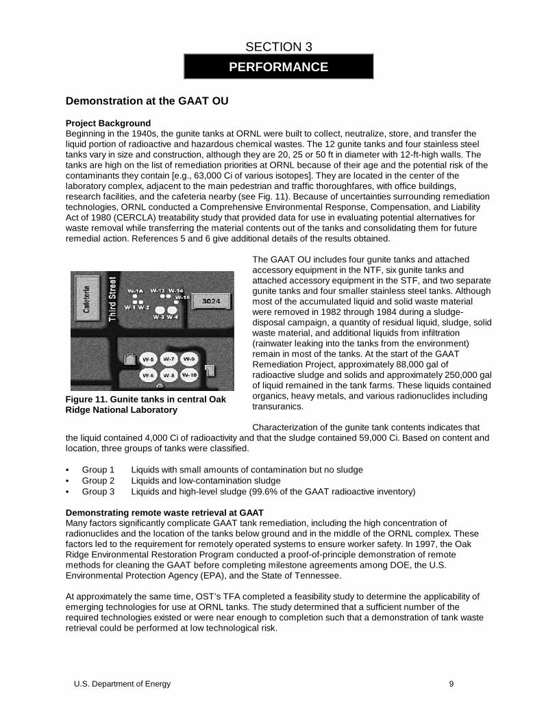
Project BackgroundBeginning in the 1940s, the gunite tanks at ORNL were built to collect, neutralize, store, and transfer theliquid portion of radioactive and hazardous chemical wastes. The 12 gunite tanks and four stainless steeltanks vary in size and construction, although they are 20, 25 or 50 ft in diameter with 12-ft-high walls. Thetanks are high on the list of remediation priorities at ORNL because of their age and the potential risk of thecontaminants they contain [e.g., 63,000 Ci of various isotopes]. They are located in the center of thelaboratory complex, adjacent to the main pedestrian and traffic thoroughfares, with office buildings,research facilities, and the cafeteria nearby (see Fig. 11). Because of uncertainties surrounding remediationtechnologies, ORNL conducted a Comprehensive Environmental Response, Compensation, and LiabilityAct of 1980 (CERCLA) treatability study that provided data for use in evaluating potential alternatives forwaste removal while transferring the material contents out of the tanks and consolidating them for futureremedial action. References 5 and 6 give additional details of the results obtained.
The GAAT OU includes four gunite tanks and attachedaccessory equipment in the NTF, six gunite tanks andattached accessory equipment in the STF, and two separategunite tanks and four smaller stainless steel tanks. Althoughmost of the accumulated liquid and solid waste materialwere removed in 1982 through 1984 during a sludge-disposal campaign, a quantity of residual liquid, sludge, solidwaste material, and additional liquids from infiltration(rainwater leaking into the tanks from the environment)remain in most of the tanks. At the start of the GAATRemediation Project, approximately 88,000 gal ofradioactive sludge and solids and approximately 250,000 galof liquid remained in the tank farms. These liquids containedorganics, heavy metals, and various radionuclides includingtransuranics.
Characterization of the gunite tank contents indicates thatthe liquid contained 4,000 Ci of radioactivity and that the sludge contained 59,000 Ci. Based on content andlocation, three groups of tanks were classified.
• Group 1 Liquids with small amounts of contamination but no sludge• Group 2 Liquids and low-contamination sludge• Group 3 Liquids and high-level sludge (99.6% of the GAAT radioactive inventory)
Demonstrating remote waste retrieval at GAATMany factors significantly complicate GAAT tank remediation, including the high concentration ofradionuclides and the location of the tanks below ground and in the middle of the ORNL complex. Thesefactors led to the requirement for remotely operated systems to ensure worker safety. In 1997, the OakRidge Environmental Restoration Program conducted a proof-of-principle demonstration of remotemethods for cleaning the GAAT before completing milestone agreements among DOE, the U.S.Environmental Protection Agency (EPA), and the State of Tennessee.
At approximately the same time, OST’s TFA completed a feasibility study to determine the applicability ofemerging technologies for use at ORNL tanks. The study determined that a sufficient number of therequired technologies existed or were near enough to completion such that a demonstration of tank wasteretrieval could be performed at low technological risk.
PERFORMANCE
Figure 11. Gunite tanks in central OakRidge National Laboratory

10 U.S. Department of Energy
A plan was developed to remove sludge and liquid wastes and transfer them to the ORNL Melton ValleyStorage Tanks. Nonpumpable objects in the tanks would also be retrieved, and a layer of scale would beremoved from the inner tank surfaces to reduce contamination. To support closure decisions, surfaceswere to be characterized using sensors and remotely collected samples, including wall corings. Remotesystems would first be used on Group 2 Tanks W-3 and W-4 in the NTF (see Fig. 12) before they wereused in Group 3 tanks in the STF. The consolidated waste would be transferred to the Melton ValleyStorage Tanks and would then be treated, packaged, and eventually shipped to the Waste Isolation PilotPlant. This approach was recently incorporated into an Interim Record of Decision.
A partnership was formed that resulted in TFA, RBX, and FETC OST organizations providing much of thehardware and controls technology, including Houdini, that together compose the GAAT Remotely OperatedTank Waste Retrieval System. The Oak Ridge EM-40 Program funded tank sampling and analysis, sitepreparation, and balance-of-plant activities and shared retrieval system development costs with EM-50programs. The net result was that only 30 months after the GAAT Treatability Study was initiated, the entiresystem was assembled and undergoing operational tests.
System development started in May 1994 and culminated in December 1996 when all major hardwaresystems were integrated for testing at ORNL’s Tanks Technology Cold Test Facility (TTCTF). An openhouse in December 1996 demonstrated the Remotely Operated Tank Waste Retrieval System to morethan 230 people from across the DOE complex. System operability evaluations and operator training thencontinued at TTCTF until May 1997.
The equipment, along with operations, support, and radiological control trailers, was then relocated to theGAAT NTF, where it was installed on a platform erected over tanks W-3 and W-4. In-tank operations inTank W-3 began in June 1997, and were completed in September 1997. The equipment was thenrelocated to Tank W-4, where operations were started in November 1997 and concluded in February 1998.In March 1998, equipment was relocated to STF, where operations began in Tank W-6 June 1998. Operations in Tank W-6 were completed inAugust 1998. Operations in Tank W-7 wereperformed from October 1998 to March 1999. Operations in Tank W-10 commenced in May1999. At this writing Tank W-10 wasteretrieval is more than 80% complete with aprojected completion date in early October1999. Waste retrieval from the remaining twotanks, W-8 and W-9, is projected to becomplete by October 2000.
GAAT waste retrieval equipmentThe major remotely operated systems forretrieving waste from the gunite tanks includeHoudini I and II; the Waste Dislodging andConveyance System, featuring the Confined Sluicing End-Effector (CSEE); the MLDUA; balance-of-plantsystems; and instrumentation and control systems. These systems can be operated independently orcooperatively in other potential applications.
Auxiliary systems for containment, decontamination, remote lighting, and observation have been developedfor each major system, along with tools that can be deployed by the arm or vehicle for tank and wastecharacterization and wall scarifying. Innovative Technology Summary Reports (ITSRs) were prepared in1998 by the TFA that more fully describes the MLDUA and CSEE (see Ref. 7and 8).
Confined sluicing, in which waste in a localized area is broken up and then pumped out using high-pressurewater, was selected because it offered an effective means of mobilizing a wide variety of waste densitiesfrom liquids to thick sludges or even material as hard as concrete. Deployment options included Houdiniand the MLDUA. ORNL demonstrated both systems and has since found them to be complementary, witheach retaining an advantage in certain applications. See Reference 9 for more information.
Fig. 12. Waste retrieval equipment at NTF.
U.S. Department of Energy 11
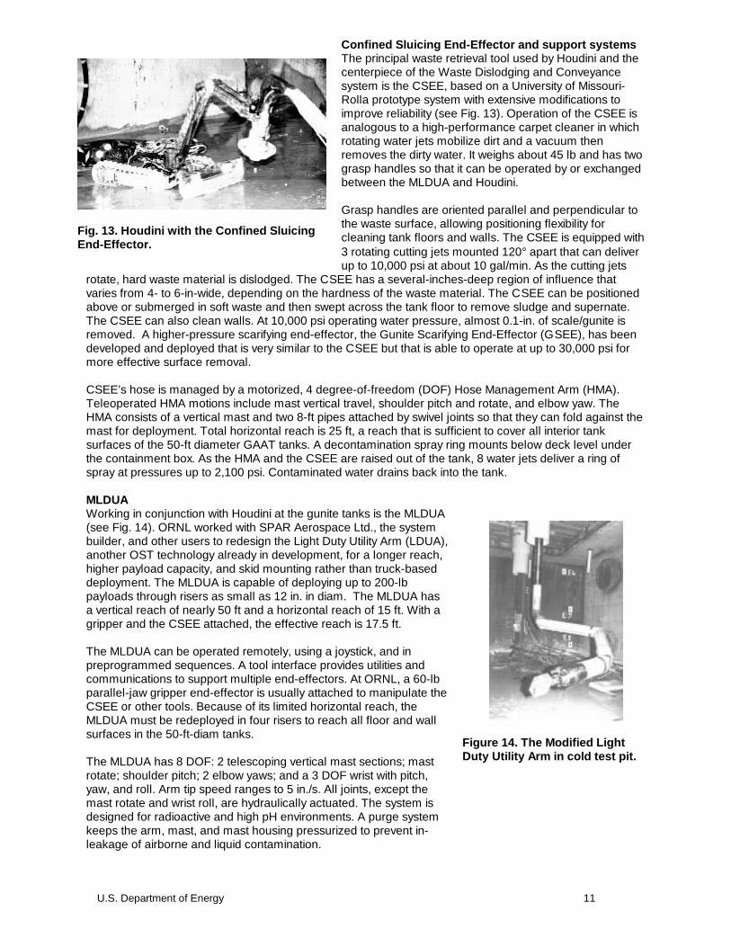
Confined Sluicing End-Effector and support systemsThe principal waste retrieval tool used by Houdini and thecenterpiece of the Waste Dislodging and Conveyancesystem is the CSEE, based on a University of Missouri-Rolla prototype system with extensive modifications toimprove reliability (see Fig. 13). Operation of the CSEE isanalogous to a high-performance carpet cleaner in whichrotating water jets mobilize dirt and a vacuum thenremoves the dirty water. It weighs about 45 lb and has twograsp handles so that it can be operated by or exchangedbetween the MLDUA and Houdini.
Grasp handles are oriented parallel and perpendicular tothe waste surface, allowing positioning flexibility forcleaning tank floors and walls. The CSEE is equipped with3 rotating cutting jets mounted 120° apart that can deliverup to 10,000 psi at about 10 gal/min. As the cutting jets
rotate, hard waste material is dislodged. The CSEE has a several-inches-deep region of influence thatvaries from 4- to 6-in-wide, depending on the hardness of the waste material. The CSEE can be positionedabove or submerged in soft waste and then swept across the tank floor to remove sludge and supernate.The CSEE can also clean walls. At 10,000 psi operating water pressure, almost 0.1-in. of scale/gunite isremoved. A higher-pressure scarifying end-effector, the Gunite Scarifying End-Effector (GSEE), has beendeveloped and deployed that is very similar to the CSEE but that is able to operate at up to 30,000 psi formore effective surface removal.
CSEE’s hose is managed by a motorized, 4 degree-of-freedom (DOF) Hose Management Arm (HMA).Teleoperated HMA motions include mast vertical travel, shoulder pitch and rotate, and elbow yaw. TheHMA consists of a vertical mast and two 8-ft pipes attached by swivel joints so that they can fold against themast for deployment. Total horizontal reach is 25 ft, a reach that is sufficient to cover all interior tanksurfaces of the 50-ft diameter GAAT tanks. A decontamination spray ring mounts below deck level underthe containment box. As the HMA and the CSEE are raised out of the tank, 8 water jets deliver a ring ofspray at pressures up to 2,100 psi. Contaminated water drains back into the tank.
MLDUAWorking in conjunction with Houdini at the gunite tanks is the MLDUA(see Fig. 14). ORNL worked with SPAR Aerospace Ltd., the systembuilder, and other users to redesign the Light Duty Utility Arm (LDUA),another OST technology already in development, for a longer reach,higher payload capacity, and skid mounting rather than truck-baseddeployment. The MLDUA is capable of deploying up to 200-lbpayloads through risers as small as 12 in. in diam. The MLDUA hasa vertical reach of nearly 50 ft and a horizontal reach of 15 ft. With agripper and the CSEE attached, the effective reach is 17.5 ft.
The MLDUA can be operated remotely, using a joystick, and inpreprogrammed sequences. A tool interface provides utilities andcommunications to support multiple end-effectors. At ORNL, a 60-lbparallel-jaw gripper end-effector is usually attached to manipulate theCSEE or other tools. Because of its limited horizontal reach, theMLDUA must be redeployed in four risers to reach all floor and wallsurfaces in the 50-ft-diam tanks.
The MLDUA has 8 DOF: 2 telescoping vertical mast sections; mastrotate; shoulder pitch; 2 elbow yaws; and a 3 DOF wrist with pitch,yaw, and roll. Arm tip speed ranges to 5 in./s. All joints, except themast rotate and wrist roll, are hydraulically actuated. The system isdesigned for radioactive and high pH environments. A purge systemkeeps the arm, mast, and mast housing pressurized to prevent in-leakage of airborne and liquid contamination.
Fig. 13. Houdini with the Confined SluicingEnd-Effector.
Figure 14. The Modified LightDuty Utility Arm in cold test pit.

12 U.S. Department of Energy
OperationsA graphical user interface allows a single operator to remotely control CSEE, HMA, and balance-of-plantsystems. A controls trailer also houses operator consoles for Houdini and MLDUA, additional remotecameras, and video recording equipment.
Cold testing the waste retrieval systemTo support the cold test program, a test facility was assembled from two unused underground experimentcells at ORNL. An observation deck was constructed in one of the cells. Above the other cell, which wasestablished as the mock storage tank, a platform was constructed to support the tank waste retrievalsystem. Risers were placed at the same separations as those in GAAT. A surrogate waste mixture ofkaolin clay, sand, gravel, and water was placed in the mock storage tank.
The TTCTF was then ready for the retrieval systems to arrive. RedZone Robotics, the vendor, completedthe production of Houdini-I in the summer of 1996 and delivered the system to ORNL in September. Delivery followed extensive testing in a mockup area at RedZone’s Pittsburgh facility. This testing includedevaluations specific to both ORNL and Fernald applications, durability runs, and final acceptance tests.
By November 1996, all equipment for the overall waste retrieval system had been delivered and installed atthe ORNL TTCTF. Meanwhile, facility modifications to support waste removal in tanks W-3 and W-4 in NTFbegan in October 1996. Modifications included adding seven 24-in. tank access ports, erecting a 40 by 70-ft steel platform to support retrieval equipment, and installing a high-efficiency, particulate air filter (HEPA)ventilation system and utilities. Individual subsystems were tested and integrated throughout the summer
and fall with each new arrival. Figures 14 and 15 showthe MLDUA and Houdini being checked out before theirhot deployment.
The test program, lasting until May of 1997, focused onthree objectives: functional checkout of all systems,validation of operating and maintenance procedures, andoperator training. The tests were structured so operatorscould validate and/or debug new procedures whileperforming tasks as would be required during hotoperations.
In the process of accomplishing these tests, many hourswere logged, enabling the operators to become familiarwith the equipment and procedures. These quality-controlled, structured tests, as well as equipmentinstallation and maintenance and repair activities, werealso used to develop and test contamination controlprocedures while still in the uncontaminated test area.
Houdini-I System PerformanceIn May 1997, Houdini was disconnected fromTTCTF and moved to the North Tank Farm. Thesystem was positioned over the north riser of TankW-3 and was powered up for the first time on June12 using the suitcase controller. Figures 16 and 17illustrate Houdini’s folding capability that allow it toenter tanks through 24-in-risers.
The system logged 150 hours of tank operationsand was deployed in the tank on 27 workdays. It wasused on numerous occasions to remove in-tankdebris including tape, pipes, cord, hand tools, plasticbags, and bottles. Houdini performed a variety oftasks, as seen in Table 1.
Fig. 15. Houdini-1 operational checkout.
Fig. 16. Houdini-Ientering
Fig. 17. Houdini-Iunfolding
U.S. Department of Energy 13
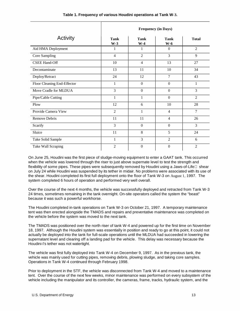
Table 1. Frequency of various Houdini operations at Tank W -3.
Frequency (in Days)
Activity TankW-3
TankW-4
TankW-6
Total
Aid HMA Deployment 1 1 0 2
Core Sampling 4 2 3 9
CSEE Hand-Off 10 4 13 27
Decontaminate 13 11 10 34
Deploy/Retract 24 12 7 43
Floor Cleaning End-Effector 1 0 0 1
Move Cradle for MLDUA 3 0 0 3
Pipe/Cable Cutting 1 1 0 2
Plow 12 6 10 28
Provide Camera View 2 1 4 7
Remove Debris 11 11 4 26
Scarify 3 0 0 3
Sluice 11 8 5 24
Take Solid Sample 1 3 2 6
Take Wall Scraping 2 0 0 2
On June 25, Houdini was the first piece of sludge-moving equipment to enter a GAAT tank. This occurredwhen the vehicle was lowered through the riser to just above supernate level to test the strength andflexibility of some pipes. These pipes were subsequently removed by Houdini using a Jaws-of-Life shearon July 24 while Houdini was suspended by its tether in midair. No problems were associated with its use ofthe shear. Houdini completed its first full deployment onto the floor of Tank W-3 on August 1, 1997. Thesystem completed 6 hours of operation and performed very well overall.
Over the course of the next 4 months, the vehicle was successfully deployed and retracted from Tank W-324 times, sometimes remaining in the tank overnight. On-site operators called the system the “beast”because it was such a powerful workhorse.
The Houdini completed in-tank operations on Tank W-3 on October 21, 1997. A temporary maintenancetent was then erected alongside the TMADS and repairs and preventative maintenance was completed onthe vehicle before the system was moved to the next tank.
The TMADS was positioned over the north riser of tank W-4 and powered up for the first time on November18, 1997. Although the Houdini system was essentially in position and ready to go at this point, it could notactually be deployed into the tank for full-scale operations until the MLDUA had succeeded in lowering thesupernatant level and clearing off a landing pad for the vehicle. This delay was necessary because theHoudini-I’s tether was not watertight.
The vehicle was first fully deployed into Tank W-4 on December 9, 1997. As in the previous tank, thevehicle was mainly used for cutting pipes, removing debris, plowing sludge, and taking core samples. Operations in Tank W-4 continued through February 1998.
Prior to deployment in the STF, the vehicle was disconnected from Tank W-4 and moved to a maintenancetent. Over the course of the next few weeks, minor maintenance was performed on every subsystem of thevehicle including the manipulator and its controller, the cameras, frame, tracks, hydraulic system, and the
14 U.S. Department of Energy
plow and tether. Modifications to the containment structure were also completed at this time. A moredetailed account of the maintenance activities performed can be found in Reference 10.
By July 17, 1998 the Houdini system had been repositioned and reconnected on Tank W-6. During the nextmonth and a half the vehicle was deployed and retracted from Tank W-6 a total of 7 times and loggedapproximately 102 hours of in-tank operations. As in Tank W-4, the vehicle was retracted only for periodicinspections and to trouble shoot and repair known problems.
Since the new and improved Houdini-II Remotely Operated Vehicle (ROV) System was scheduled to takeover tank farm operations starting with the next tank, W-7, the original Houdini system was disconnected onAugust 28, 1998.
Overall reviewEven though Houdini-I was still a prototype system during its GAAT deployments, it proved its versatility: Ithas been used more frequently and tested in applications far beyond those originally planned:• It deployed sluicing and characterization end-effectors.• It plowed waste to the CSEE as the confined sluicer was being held by the MLDUA for maximum
retrieval efficiency.• It removed nonpumpable objects.• It proved to be the only system capable of deploying such tools as the Jaws-of-Life, a mobile-
hydraulic shear, and a wall-coring end-effector for sampling gunite tank walls.
The Houdini-I system had significantly more downtime than anticipated. Such heavy-duty testing of a first-generation system resulted in numerous breakdowns that brought many design issues to light. Furtherdiscussion of maintenance issues is found in Sect. 7. The most consistent failure of the system washydraulic leaks. The Titan-III manipulator wrist rotate joint performed erratically while the Houdini was takinga bulk sludge sample from Tank W-3 on August 6. The erratic performance of the manipulator continued tobe a problem during its use on Tank W-4. Although temporarily corrected by replacing a resolver duringthe maintenance campaign before beginning Tank W-6 operations, the problem reappeared before wasteremoval from that tank was completed.
Houdini-II System Performance
Houdini-II was powered up and checked out for the first time on Tank W-7 on January 26, 1999. The firstdeployment and retraction of the vehicle occurred on January 28 when the system was lowered into thetank to perform a final procedure verification and to ensure that all systems were functioning properly.
Full-scale operations began in earnest on January 29, 1999. Over the next 6 weeks the vehicle spent abouteighty hours picking up debris and plowing sludge to the CSEE while the end-effector was held in positionby the MLDUA. Five core samples were also removed from the tank walls during one shift as the Houdini-IIwielded the coring end-effector.
A number of minor hardware failures were encountered and corrected during the Tank W-7 operations. The tilt-down function of the body camera was lost during the first full day of operation; however, the effectof this failure on plowing operations was negligible. A few hydraulic leaks also sprung up in variouslocations such as on the Titan III manipulator, on the plow cylinder and on both the left and right track drivemotors. The manifold plugs and frame bolts loosened periodically and had to be inspected and tightened. All of these failures were successfully repaired while the vehicle was stowed in the TMADS.
On March 10, 1999 the Titan III manipulator began to demonstrate some disturbing characteristics. Thewrist rotate and gripper open/close functions failed. In addition, the arm began to shake vigorously (as if inthe throes of an epileptic seizure) whenever the manipulator hydraulics were enabled. Since wasteremoval operations were nearly complete on tank W-7 at this point, the arm was positioned out of theplow’s way and then disabled or “frozen” in place. Plowing operations were completed on March 13, 1999.
The Houdini-II system lead spent several weeks troubleshooting the manipulator malfunction(s), with someassistance from the Schilling Development Corp. field technician. After swapping out the master controllerand several of the printed circuit boards on the slave controller, the problem was eventually traced to afailure at the tether termination on the vehicle. Fluid had leaked into the termination canister and caused
U.S. Department of Energy 15
several wires on the manipulator controller cable to short together until the wires burnt in two. Also duringthis period, a tear developed in the outer jacket of the tether. Neither failure of the tether could be repairedsatisfactorily so the tether had to be replaced. Installation of the new tether was completed in lateSeptember 1999. During final editing of this ITSR, the system was being relocated from the MaintenanceTent to tank W-10 to assist in the final clean-out of sludge waste, debris, and in collection of core samples.
Waste retrieval performanceThe Houdini systems and the MLDUA worked well both independently and together. Sluicing operationswere most efficient when the plow on Houdini pushed sludge toward the MLDUA. The MLDUA worked bestfor bulk wall cleaning, while Houdini was better at collecting the residual (<8 in.) sludge on the floor andplowing it to the CSEE while it was held by the MLDUA.
Houdini was used on numerous occasions to assist the MLDUA by retrieving and handing off end-effectorsthat were either out of the arm’s reach or not in the proper orientation for the MLDUA to pick up. Additionaltools were quickly integrated and used by Houdini, based upon emerging situations encountered during thecampaign. These tools included the shear tool, a wall scraper, and a small modified vacuum cleaner usedfor final cleaning.
Houdini obtained core samples that revealed that more than 90% of the wall contamination was in the first1/8 in of depth. Walls were cleaned using the MLDUA with either the CSEE or the GSEE to remove much ofthe scale and loose contamination. During wall cleaning, a dense fog limited visibility. The MLDUA wasmore suitable for scarifying under these conditions since the scarifying paths could be preprogrammed. Asurvey of the walls by characterization end-effectors showed that the dose rate from the walls was reducedby about 20% in the NTF and about 50% in the more highly contaminated walls in the STF. Visualobservation indicated that almost all of the wall scale was removed with the GSEE.
After water from the wall cleaning was pumped out, a small amount of grit remained on the tank floor. Anattempt was made to plow the material into piles, but this was unsuccessful. A new end-effector wasdesigned to link up to a vacuum system for final tank cleaning without adding any more water.
Success measures in Tanks W-3, W-4, W-6 and W-7• Approximately 35,500 gal of supernate, 26,000 gal of sludge, and various in-tank debris were removed.• Total radioactivity in Tanks W-3, W-4, W-6 and W-7 was reduced from 8092 Ci to 795 Ci, a 90%
reduction of inventory.• Residual liquid and sludge was estimated at 1500 gal.• The State of Tennessee agreed that the Interim Record of Decision (IROD) goals had been achieved
for Tank W-3, W-4, W-6 and W-7.
16 U.S. Department of Energy
SECTION 4
Competing Technologies
Past practice for tank waste retrieval is to use large volumes of water to mobilize and remove the wastematerial. Although this approach has been found to be acceptable for bulk removal of some physical wasteforms, it is not appropriate for hard or adhesive wastes and does not address residual quantities leftafterwards (the heel) or the management and removal of in-tank debris.
Before remote systems became available for tank remediation projects, the only baseline alternatives wereimpractical:• Manned entry through existing ports.• Development and use of long-handled manual tools.• Overburden and tank-dome removal, construction of a containment building, and then manned entry.
Within the class of remote systems, two types of complementary and nonexclusive approaches have beenconsidered:• Long-reach arms and• ROVs like Houdini.
Different approaches and systems have been developed in both subcategories, and the marketplace is stillgrowing in part due to successes noted in this Houdini program. For now, however, the focus is on thosesystems that have been demonstrated and deployed.
Long-reach armsLong-reach arms are deployed into tanks through a single access port and then extend too much of theinterior surface and volume of the tank. The MLDUA, used on the GAAT project and previously introducedin this report, is an example of this approach. The long extension of the arm results in lower payloadcapacity and gives it a tendency to vibration and tip location inaccuracy. Limitations of arm motions oftenresult in surface and volume areas being unreachable in certain configurations, such as above the elbow. Ifheadspace is limited, the arm may not be able to enter the tank.
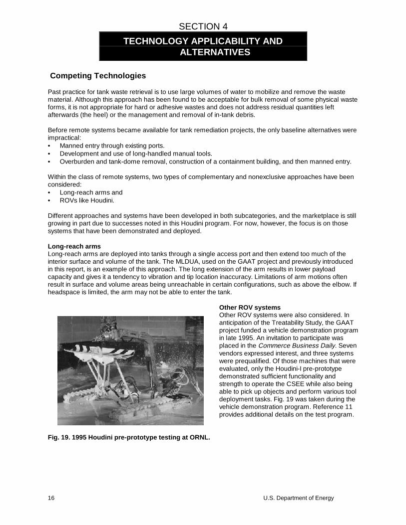
Other ROV systemsOther ROV systems were also considered. Inanticipation of the Treatability Study, the GAATproject funded a vehicle demonstration programin late 1995. An invitation to participate wasplaced in the Commerce Business Daily. Sevenvendors expressed interest, and three systemswere prequalified. Of those machines that wereevaluated, only the Houdini-I pre-prototypedemonstrated sufficient functionality andstrength to operate the CSEE while also beingable to pick up objects and perform various tooldeployment tasks. Fig. 19 was taken during thevehicle demonstration program. Reference 11provides additional details on the test program.
TECHNOLOGY APPLICABILITY ANDALTERNATIVES
Fig. 19. 1995 Houdini pre-prototype testing at ORNL.
U.S. Department of Energy 17
Technology Applicability
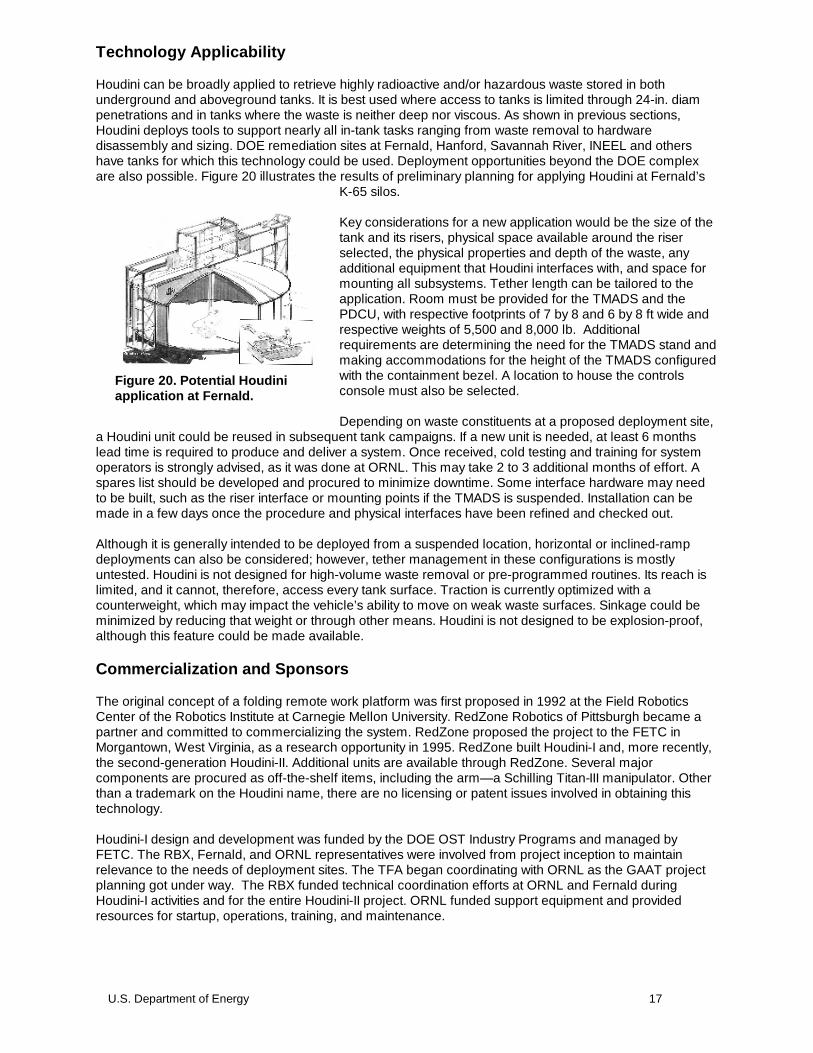
Houdini can be broadly applied to retrieve highly radioactive and/or hazardous waste stored in bothunderground and aboveground tanks. It is best used where access to tanks is limited through 24-in. diampenetrations and in tanks where the waste is neither deep nor viscous. As shown in previous sections,Houdini deploys tools to support nearly all in-tank tasks ranging from waste removal to hardwaredisassembly and sizing. DOE remediation sites at Fernald, Hanford, Savannah River, INEEL and othershave tanks for which this technology could be used. Deployment opportunities beyond the DOE complexare also possible. Figure 20 illustrates the results of preliminary planning for applying Houdini at Fernald’s
K-65 silos.
Key considerations for a new application would be the size of thetank and its risers, physical space available around the riserselected, the physical properties and depth of the waste, anyadditional equipment that Houdini interfaces with, and space formounting all subsystems. Tether length can be tailored to theapplication. Room must be provided for the TMADS and thePDCU, with respective footprints of 7 by 8 and 6 by 8 ft wide andrespective weights of 5,500 and 8,000 lb. Additionalrequirements are determining the need for the TMADS stand andmaking accommodations for the height of the TMADS configuredwith the containment bezel. A location to house the controlsconsole must also be selected.
Depending on waste constituents at a proposed deployment site,a Houdini unit could be reused in subsequent tank campaigns. If a new unit is needed, at least 6 monthslead time is required to produce and deliver a system. Once received, cold testing and training for systemoperators is strongly advised, as it was done at ORNL. This may take 2 to 3 additional months of effort. Aspares list should be developed and procured to minimize downtime. Some interface hardware may needto be built, such as the riser interface or mounting points if the TMADS is suspended. Installation can bemade in a few days once the procedure and physical interfaces have been refined and checked out.
Although it is generally intended to be deployed from a suspended location, horizontal or inclined-rampdeployments can also be considered; however, tether management in these configurations is mostlyuntested. Houdini is not designed for high-volume waste removal or pre-programmed routines. Its reach islimited, and it cannot, therefore, access every tank surface. Traction is currently optimized with acounterweight, which may impact the vehicle’s ability to move on weak waste surfaces. Sinkage could beminimized by reducing that weight or through other means. Houdini is not designed to be explosion-proof,although this feature could be made available.
Commercialization and Sponsors
The original concept of a folding remote work platform was first proposed in 1992 at the Field RoboticsCenter of the Robotics Institute at Carnegie Mellon University. RedZone Robotics of Pittsburgh became apartner and committed to commercializing the system. RedZone proposed the project to the FETC inMorgantown, West Virginia, as a research opportunity in 1995. RedZone built Houdini-I and, more recently,the second-generation Houdini-II. Additional units are available through RedZone. Several majorcomponents are procured as off-the-shelf items, including the arm—a Schilling Titan-III manipulator. Otherthan a trademark on the Houdini name, there are no licensing or patent issues involved in obtaining thistechnology.
Houdini-I design and development was funded by the DOE OST Industry Programs and managed byFETC. The RBX, Fernald, and ORNL representatives were involved from project inception to maintainrelevance to the needs of deployment sites. The TFA began coordinating with ORNL as the GAAT projectplanning got under way. The RBX funded technical coordination efforts at ORNL and Fernald duringHoudini-I activities and for the entire Houdini-II project. ORNL funded support equipment and providedresources for startup, operations, training, and maintenance.
Figure 20. Potential Houdiniapplication at Fernald.

18 U.S. Department of Energy
SECTION 5
Methodology
For Houdini, standard analysis of cost and benefits, as compared to baseline budgets and technicalapproaches, is not possible since Houdini was used in situations for which there are no other legitimateapproaches for tackling waste retrieval tasks. However, significant savings and schedule acceleration canand have been quantified for the overall GAAT project at ORNL, where Houdini was one of the keyenabling technologies contributing to the project’s success. In the following subsection, three methods ofapproximating the cost savings attributable to Houdini are presented, using different bases of analysis andpresented in increasing level of detail:
1. GAAT project baseline reduction2. Worker annual dose limits, productivity, and initial training costs3. Radiation dosage reduction and comprehensive life-cycle costs
Because baseline data for the overall GAAT project is available, an estimate of Houdini’s contribution canbe made. However, it is impossible to accurately quantify the cost savings from each individual wasteretrieval technology deployed at GAAT.
Another approach for estimating Houdini’s contribution to cost reduction is to calculate a dollar value thatrepresents workers’ avoidance of radiation exposure. This value is based on the minimum number ofworkers required for manned entry, which is affected by annual radiation dosage limitations imposed byALARA requirements. The occupational exposure limit varies by site across DOE, but in practice it is limitedto 1,000 to 1,500 mR/year.
Costs avoided through reducing worker dosage can be estimated using a cost model developed by theradiation engineering organization at INEEL. (See Appendix A). Though the absolute accuracy of the modelhas not been extensively tested, it illustrates, at a greater level of detail, the many elements of cost that areinherent with work in high-radiation environments—not only high levels of background and job-specifictraining, but also expensive consumerable personal protective equipment (PPE), such as suits andbreathing apparatus that reduce productivity and eventually contribute to contaminated waste. Thisinvestigation of costs to mitigate the hazards of manned entry highlights the clear superiority of remoteoperations from the perspectives of cost, worker safety, and production efficiency.
All these results collectively and qualitatively demonstrate the elements of cost savings and how theycombine to yield significant benefit. As is shown below, all three analyses indicate the same range ofsavings for the deployment of Houdini at GAAT—in the range of $30 to $50 million. Comparing this savingsto OST’s investment of $4 to $5 million yields a return on investment as high as 10 to 1. Furthermore, thesesavings apply to Houdini’s use at ORNL alone; the use of this technology at other sites would yieldadditional cost savings.
Cost Analysis
First costing method: GAAT project baseline reduction
Preliminary cost information obtained from GAAT Project Management supports the conclusion that wasteretrieval equipment at the GAA project, including Houdini, accelerated waste retrieval operations by 13years and yielded $120 million in cost savings. Retrieval equipment reduced overall costs from $196million to $76 million and shortened the projected completion date from 2015 to 2002. Assuming that 25%of the savings is attributable to Houdini (with the remainder being attributable to the other systems),Houdini’s share of overall cost savings would be about $30 million.
COST
U.S. Department of Energy 19
Second costing method: Worker annual dose limits, productivity, and initial training costs
Planning work in a highly radioactive environment involves many considerations. Foremost are therestrictions on worker radiation dose, with whole-body occupational exposure limits ranging from 1,000 to1,500 mR per year at various DOE sites. Generally, about twice as many workers are required to perform atask within a highly radioactive environment as compared to workers in a standard industrial setting. Forinstance, suiting up and getting out of PPE is both costly and time-consuming, resulting in lower than 50%actual productivity. Much PPE is consumable, such as outer gloves and suits, and becomes contaminatedtrash, compounding the problem of waste generation. Stay times are also limited, and frequent breaks arerequired; thus the total number of entries into the tank (and thus new PPE and generated waste) is typicallyat least four per day for an individual worker.
The objective in this section is to calculate the cost savings that accrue from avoiding the exposure ofworkers to the radiation in tanks. The total dose that would be incurred if workers entered the tanks is basedon the time it actually took for Houdini to perform inside the tanks since there are no similar tasks doneoutside the tanks. Using occupational dose restrictions that limit individual workers to 1,500 mR per year,the number of workers for manned entry is derived—the minimum number of workers that are required toavoid any worker exceeding the dose limitation. Finally, using a coarse and conservative estimate of thecosts to train that many workers, a dollar value is estimated for the radiation dose avoided.
If this job were actually done with manned entry, every effort would be made by health physics and safetyteams to design procedures and shielding to protect workers while still getting the essential work done. Thecost of those activities and related equipment would certainly exceed any savings associated with thereduced worker dose.
For the purposes of this estimate then, simplifying the basis to training costs alone is a reasonablyconservative assumption. Training is the single greatest cost in preparing workers for the rigors of work inradioactive environments. At the least, initial training includes Occupational Safety and HealthAdministration (OSHA) Hazardous Worker, Radiation Worker-II, and respirator training over 3 weeks.Annual refresher courses are needed thereafter and are conservatively estimated to take a week tocomplete. In addition, job- and site-specific training are required. From the INEEL study (Appendix A, p.A-2),total initial training is reported to be about $4,000/worker.
At ORNL, Houdini has seen 270 hours of service operating in Tanks W-3 and W-4 at the GAATdemonstration over a period of 4 months. A two-man crew would be required to perform the same numberof hours of activity because of the extensive work requirements. Average radioactivity inside the NTF tankswas 500 mR/h, and thus, the crew would receive a total exposure of 270 man-rem as follows:
500 mR/h x 2 workers x 270 hours of service = 270 man-rem
Conservatively assuming the higher 1,500 mR/year limit, that amount of exposure would require at least 90workers over which to spread the dose to avoid any one worker exceeding the dose restriction:
270 man-rem / 1,500 mR/year = 90 workers
Activities at NTF have only removed about 600 Ci, or 0.95% of the total curie content in the GAAT OU of63,000 Ci. The potential radiation exposure in man-rem saved for the overall gunite tanks project (and thuscost savings) is directly proportional to both the relative curie content and also dose as measured in Rads(R or mR).
If removal of 1% of the curie inventory takes 90 workers, then the entire job will take 100 times as many, or9,000 workers—the population of a moderate-sized town. With each worker costing at least $4,000 to train(in 1995 dollars), the total cost avoided through the use of Houdini is $36 million (9,000 workers x$4K/each). If workers are reused in subsequent years, retraining costs are reduced, although the figure of$4K/worker significantly understates current year training costs. Given the conservative estimates in thisanalysis, the actual costs would probably be much higher.

20 U.S. Department of Energy
Third costing method: Radiation dosage reduction and comprehensive life-cycle costs
This analysis compares Houdini and manned entry on the basis of life-cycle operations costs and ispredicated on the referenced INEEL study that was completed in 1995. This analysis results in a value forthe cost incurred per man-rem of worker occupational radiation exposure. As the INEEL study shows, life-cycle costs are dominated by worker training but also include many other elements, such as the cost ofsuits, respirator equipment, management of secondary waste, and prejob briefings. In the followinganalysis, elements of cost from the INEEL model are combined with additional health physics (HP) supportand the cost of the workers themselves, and adjusted for inflation. Starting with the lower figure of $3,795(see the second table in Appendix A, p. A-2), the overall cost can be conservatively estimated at $5K/man-rem, as shown Table 1.
Table 1. Calculating the value of avoided radiation exposure
Description Factor 1 Factor 2 Cost ($) Assumptions
Estimate plus 3 years’escalation (FY95–98)
$3,795 5%/year =15.7%
4,393 - 5% escalation per year- 125 mR/h whole body exposure rate- Worker and HP costs in present dollars using ORNL-loaded rates- Full-time HP oversight required- 8 hours in-tank per man-rem- Full PPE required
HP support 10 h $69/h 690
Worker 12 h $51/h 612
Total cost 5,695
Typical cost per man-rem $5,000
As shown in the second analysis, a manned crew would receive a total exposure of 270 man-rem in theexecution of NTF in-tank activities. Thus, at the conservative estimate of $5,000/man-rem, $1,350,000 wassaved in exposure costs just in the two tanks at NTF as follows:
$5,000 x 270 man-rem = $1,350,000
The overall GAAT project has had monthly operating costs of about $25,000 per day. Conservativelyassuming that 25% of the operating costs, including maintenance, training, spares, and operator labor, areattributable to Houdini, a total of $760K in Houdini operating costs were incurred during the 4-month-longcampaign in both tanks:
$25K/d x 25% x 4/12 months x 365 d/year = $760,000
Thus, total cost savings are $590K ($1,350K - $760K) for Houdini’s use at NTF alone. More operations andsavings are expected in the STF tanks with their much higher radioactivity levels. With 600 Ci, or 0.95% ofthe total curie inventory removed, a cost savings of $590K was achieved. Assuming that 95% of total curieinventory is also removed from contents of the remaining tanks (100% ~1% = 99%), an additional 94%(95% x 99%) of the total potential man-rem dose savings will be accrued. With total savings proportional torelative dose, a total savings of $55 million is derived from the ratio of achieved and future avoidedexposure as follows:
Savings = (94%/1%) x $590K = $55.4M
Clearly, some uncertainty exists as to the scaling of the cost model to various radiological hazard levels.Quite possibly, though, in the highest radiation-level cases, the value jumps disproportionately higher sincethose are the cases where there is really no other way to do the job.

U.S. Department of Energy 21
Cost Conclusions
Three cost models, using data ranging from net savings over the baseline approach to rough worker burn-out estimates and conservative assumptions, have demonstrated cost savings between $32 million and $55million. Deducting OST’s $5 million investment in Houdini’s development (both Houdini-I and Houdini-II), areturn on investment as high as 10 to 1 can be achieved at ORNL’s GAAT project alone.
22 U.S. Department of Energy
SECTION 6
Regulatory Considerations
No special permits are required to operate either of the Houdini systems. In radioactive tank cleanup, theywould generally be used as part of a CERCLA or RCRA project with all necessary permitting andenvironmental impact issues considered. That was the case with the Houdini demonstration at ORNL,where the waste retrieval demonstration was in support of treatability studies that led to the definition of theretrieval approach for the remaining tanks in the OU. Because Houdini has contributed only to the overallremediation, information was not needed on the nine specific CERCLA criteria.
Houdini is far superior to baseline technologies in complying with ALARA exposure goals because itdramatically reduces worker exposure.
Secondary waste streams generated during Houdini operations include expended parts; decontaminationsupplies; and, ultimately, disposal of the robot itself. Parts expended in operations will be contaminated andmust be disposed of as waste. Expended decontamination supplies will be limited, however, if a water-based cleaning system can be used with runoff draining back into the tank. If this is not possible, othermethods of decontamination may result in secondary waste. A minor amount of waste consists ofcontaminated glove bags that are used to pass objects for retrieval or maintenance.
The robot can be reused at subsequent sites if the hazardous and radiologic constituents of the waste arecompatible. Since it cannot be completely decontaminated, some material will remain in the vehicle andstorage system, which could cross-contaminate a new site if the materials are incompatible (such as mixinghazardous and radioactive waste). At the end of its useful life, the robot will, therefore, have to be disposedof as waste.
Because of the regulatory complications that come along with creating mixed waste, the selection ofworking fluid for Houdini’s hydraulic system should be carefully considered. Normal hydraulic fluid ispetroleum based, and amounts over a certain threshold that leak into the tank from ruptured hoses andfittings could cause regulatory problems. The exact amount that would cause a problem depends on thetype of waste and is subject to interpretation. Alternatives are available, however. Water/glycol-based fluidsdo not present regulatory difficulty, but they will reduce the life of the equipment through increased wear(see Sect. 7 for more details). Mineral- and vegetable-oil-based fluids are also now being marketed thathave better lubricity.
Safety, Risks, and Community Reaction
Houdini reduces the risks associated with high exposure to radiation while following good ALARA andindustrial hygiene practices. As with any piece of heavy machinery, though, hazards exist that must bemitigated. The primary danger exists during equipment maintenance when workers may come into contactwith contaminated material stuck to the robot in the TMADS. The steel panels help mitigate that potential,however. In the redesigned TMADS for Houdini-II, even more consideration has been given to improvingease of maintenance so as to lower exposures during repair.
During nonroutine maintenance, the potential for contaminant release must be carefully controlled sincetemporary containment structures and glove bags have to be used to get the vehicle out of the TMADS forrepair. HEPA-filtered negative pressure in the tank and the TMADS compartments can minimize the risk ofthese leaks.
Safety reviewers have questioned whether a Houdini collision into tank walls could affect waste-confinement integrity. Assuming a failure in all speed-limiting hardware and operation at the highest systempressure available, the vehicle would travel at only 3 ft/s, which would not affect any tank with at leastminimally acceptable structural integrity. Other potential hazards from the hydraulic system (3000 psi) and
REGULATORY AND POLICYISSUES
U.S. Department of Energy 23
electrical energy (480 VAC) associated with the Houdini systems are mitigated by using standard industrialcontrols.
The most significant physical hazards are those associated with hoisting, and precautions have been takenin the design to account for them. At cold-test facilities, workers could conceivably be under the robot as ithangs in the TMADS. Safety chains have been included to give additional protection, supplementing fail-safe brakes on the tether drum drive motor. When reviewed at Fernald, the tether and its connections to thedrum and vehicle were given the next highest hazard category beyond that for standard industrial hazards.The rationale for this hazard category is that losing Houdini in the tank could adversely affect the overallmission. In response, RedZone overdesigned these components and implemented destructive testing of asample of the tether, with a minimum required proof load of 10,000 lb, 10 times the normal vehicle weight.This is also over 3 times the 3,000-lb maximum pull force developed by the tether drive motor.
Since, in the balance, Houdini is an important tool in lowering risks through successful waste retrieval whereit would otherwise not be possible, the public’s and community’s perception of the system has been quitepositive. Being a novel remote system, it’s an object of the public’s interest and curiosity. The only potentialliability or risk to the community would be contaminant leakage during repairs. That risk can easily bemitigated through standard glove bagging, negative air pressure, and other radiological controls.
24 U.S. Department of Energy
SECTION 7
Implementation Considerations
Technical and regulatory constraints must be considered early in any proposed waste retrieval project, andadequate lead time for equipment design, integration, and most particularly operator training must beprovided. This section describes technical deficiencies in Houdini-I and how they were addressed in theHoudini-II design and finally how successfully those changes were implemented in that system.
Houdini maintenance experienceAlthough Houdini-I has had the reliability of a prototype, ORNL operators report that no showstoppers havebeen found. Experience gained from maintenance activities, while unwelcome, have provided a wealth ofdata for system improvements for Houdini-II. Many of these design improvements were incorporated intothe next system to make it more reliable.
Some significant problems were brought to light and corrected while the Houdini-I system was stillundergoing cold testing at ORNL. For instance, a water/glycol fluid initially used for the hydraulic systemwas found to cause an inordinate number of failures in the valves located on the vehicle and in the TMADS.The electrically conductive water/glycol fluid also caused electrical short circuits on the manipulator when afailed servo valve allowed the fluid to flood the arm’s housing. The water/glycol fluid was replaced by ShellTellus 32, a mineral-oil-based fluid before Houdini was moved to the NTF.
The manipulator supplied with Houdini-I had to be replaced before deployment of that system. The housingon the original Titan-II was open at the shoulder and allowed handfuls of sludge to collect inside the armduring mock retrieval and decontamination operations. These pockets of sludge could be removed only bydisassembling the arm. Therefore, the Titan-II was replaced with a Titan-III since the housing on thatversion is sealed at the shoulder.
Leaking or damaged hydraulic hoses, electrical cables, and connectors have been the most persistentproblems with the Houdini-I system. Many of the connectors were subject to damage or loosening when thevehicle was folded during retractions and deployments. The most common failure point was at the elbowfittings to the track drive manifolds. The connectors loosened and had to be tightened weekly. It was alsoduring these operations that the hoses sometimes pinched. Fixes on the Houdini-I system were limited tocontrolling hose routing with wire ties, daily inspections of all hoses, and weekly tightening of all connectors.Loosening of fasteners was also a frequent complaint. Following numerous in-service repairs accomplishedthrough the glove ports on the TMADS during Tank W-3 operations, the robot was refurbished before it wasrelocated to Tank W-4. A maintenance tent was erected on the GAAT platform next to the TMADS. Aplastic corridor supported by wood framing was built between the two structures to maintain containmentwhile a side panel on the TMADS was opened and Houdini was pulled out and lowered onto a table in thetent. Every fitting, connection, and fastener on the vehicle was tightened.
The relief valve for the manipulator (located on the azimuth) was damaged during a retraction of the vehiclefrom the tank. This valve was easily replaced while the vehicle was stored in the TMADS. Both vehicle-mounted cameras sustained damage during deployments and retractions. On the manipulator camera,power and signal cables were cut and had to be respliced in the containment bezel. This was an extremelydifficult operation to perform through glove ports. A connector was added at the tether termination so that inthe future the entire cable can be replaced if necessary. Mounting screws on the body camera loosenedfrequently even when a thread-locking compound was applied. The unit was, in general, prone to damageduring deployments and retractions and loosening of fasteners from vibration during normal tankoperations.
The Houdini-I TMADS door is hydraulically actuated and occasionally has failed to open or close. Thisproblem was traced to a faulty counterbalance valve system and leakage across valve ports. When thehydraulic valve that controlled the latch failed, there was no way to reach the valve without cutting a hole inthe frame. This was done, and a bolt-on panel was added in case the need should arise to access thepanel again in the future.
LESSONS LEARNED
U.S. Department of Energy 25
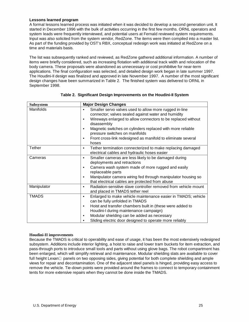
Lessons learned programA formal lessons learned process was initiated when it was decided to develop a second generation unit. Itstarted in December 1996 with the bulk of activities occurring in the first few months. ORNL operators andsystem leads were frequently interviewed, and potential users at Fernald reviewed system requirements.Input was also solicited from the system vendor, RedZone. The items were then compiled into a master list.As part of the funding provided by OST’s RBX, conceptual redesign work was initiated at RedZone on atime and materials basis.
The list was subsequently ranked and reviewed, as RedZone gathered additional information. A number ofitems were briefly considered, such as increasing flotation with additional track width and relocation of thebody camera. These proposals were abandoned as unnecessary or cost prohibitive for near-termapplications. The final configuration was selected, and detailed design work began in late summer 1997.The Houdini-II design was finalized and approved in late November 1997. A number of the most significantdesign changes have been summarized in Table 2. The finished system was delivered to ORNL inSeptember 1998.
Table 2. Significant Design Improvements on the Houdini-II System
Subsystem Major Design ChangesManifolds • Smaller servo valves used to allow more rugged in-line
connector; valves sealed against water and humidity• Wireways enlarged to allow connectors to be replaced without
disassembly• Magnetic switches on cylinders replaced with more reliable
pressure switches on manifolds• Front cross-link redesigned as manifold to eliminate several
hosesTether • Tether termination connecterized to make replacing damaged
electrical cables and hydraulic hoses easierCameras • Smaller cameras are less likely to be damaged during
deployments and retractions• Camera wash system made of more rugged and easily
replaceable parts• Manipulator camera wiring fed through manipulator housing so
that electrical cables are protected from abuseManipulator • Radiation-sensitive slave controller removed from vehicle mount
and placed in TMADS tether reelTMADS • Enlarged to make vehicle maintenance easier in TMADS; vehicle
can be fully unfolded in TMADS• Hoist and transfer chambers built in (these were added to
Houdini-I during maintenance campaign)• Modular shielding can be added as necessary• Sliding electric door designed to operate more reliably
Houdini-II improvementsBecause the TMADS is critical to operability and ease of usage, it has been the most extensively redesignedsubsystem. Additions include interior lighting, a hoist to raise and lower tram buckets for item extraction, andpass-through ports to introduce small tools and parts without using glove bags. The robot compartment hasbeen enlarged, which will simplify retrieval and maintenance. Modular shielding slats are available to coverfull height Lexan panels on two opposing sides, giving potential for both complete shielding and ampleviews for repair and decontamination. One of the adjacent steel panels is hinged, providing easy access toremove the vehicle. Tie-down points were provided around the frames to connect to temporary containmenttents for more extensive repairs when they cannot be done inside the TMADS.

26 U.S. Department of Energy
As shown in Fig. 22, the TMADS on Houdini-II has a more rectangular profile so that it can be free-standingalthough the heavy steel stand is still used at ORNL as continued precaution against high winds. The semi-sealed door at the bottom now closes with a linear motion across the opening. It is a sealed module with anelectric motor, guides, and seals enclosed. The containment bezel has been incorporated as an integratedpart of the TMADS, giving extra height in the compartment to retract the robot without needing to fold itsarm.
Bolt patterns on both the top and bottom of the containment bezel are the same, with the door usuallymating below it and the remainder of the TMADS above. To improve its usefulness at other deployment
sites, the containment bezel may be optionally removed so that TMADS can be reduced from its normalheight of 19 ft to just over 16 ft, making it easier to fit into an interior space such as at Fernald.
The vehicle has been extensively redesigned for improved durability (see Fig. 22). Hydraulic hoses andloose electric wires have been eliminated in some cases and rerouted in others. Additional pinned andlocking elements have been added to strengthen frame connections. The plow blade, hydraulic manifoldand valves, and tether termination designs have been improved. The controller for the robot arm has beenmoved up to the TMADS, and new cameras have been selected. Due to the many revisions, the numberand type of lines that pass through the tether have changed. Significant revisions have been made to thehydraulic pump in the PDCU as well as the overall hydraulic circuit. Many other improvements have beenmade.
Figure 21 The Houdini-II TMADS (picture do right) provided a sleeker design with more room formaintenance activities than the Houdini-I TMADS had provided (pictured on left).
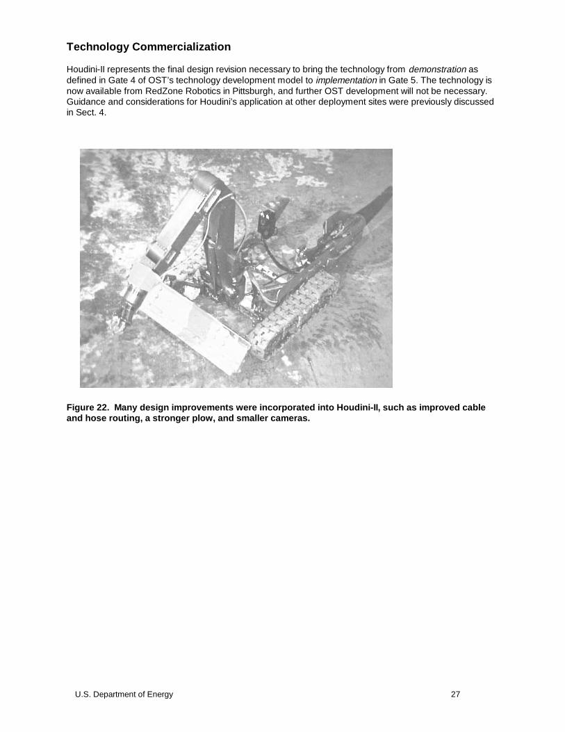
U.S. Department of Energy 27
Technology Commercialization
Houdini-II represents the final design revision necessary to bring the technology from demonstration asdefined in Gate 4 of OST’s technology development model to implementation in Gate 5. The technology isnow available from RedZone Robotics in Pittsburgh, and further OST development will not be necessary.Guidance and considerations for Houdini’s application at other deployment sites were previously discussedin Sect. 4.
Figure 22. Many design improvements were incorporated into Houdini-II, such as improved cableand hose routing, a stronger plow, and smaller cameras.
28 U.S. Department of Energy
APPENDIX A
1. DOE/EM-0363, Houdini I and II Remotely Operated Vehicle System Innovative TechnologySummary Report, July, 1998.
2. Denmeade, T. J., A. D. Slifko, and B. R. Thompson. “HoudiniTM: A Remote Mobile Platform forTank Waste Retrieval Tasks,” pp. 682-689 in Proc. ANS Seventh Topical Meeting on Robotics andRemote Systems, Augusta, Georgia, April 27–May 1, 1997.
3. RedZone Robotics. Houdini: Reconfigurable In-Tank Robot Pre-fabrication Design Document,9411-REPT-012.1, Feb. 12, 1996.
4. RedZone Robotics. Houdini-II: Reconfigurable In-Tank Robot Pre-fabrication Design Document,97005-REPT-003.2, Nov. 24, 1997.
5. Oak Ridge National Laboratory. Addendum to the Remedial Investigation/Baseline RiskAssessment for the Gunite and Associated Tanks Operable Unit at Waste Area Grouping 1 at theOak Ridge National Laboratory, DOE/OR/02-1275&D2/A1, Oak Ridge, Tenn.
6. Oak Ridge National Laboratory. Gunite and Associated Tanks Operable Unit Baseline Report andTreatability Study Work Plan, Document DOE/OR/02-1325&D2, Oak Ridge, TN. October 1995.
7. DOE/EM-0406, Light Duty Utility Arm Innovative Technology Summary Report, December 1998.
8. DOE/EM-0372, Confined Sluicing End-Effector Innovative Technology Summary Report,September 1998.
9. Randolph, J. D., P. D. Lloyd, M. A. Johnson, B. L. Burks, J. Blank, D. Summers, M. W. Rinker, D.Mullen, and D. Alberts. “Development of a Waste Dislodging and Retrieval System for Use in theOak Ridge National Laboratory Gunite Tanks,” pp. 894-906 in Proc ANS Seventh Topical Meetingon Robotics and Remote Systems, Augusta, GA, April 27–May 1, 1997.
10. Falter, D. D., Burks, B. L., Glover, W. H., Hazen, F. B., Vesco, D. P. and Slifko, A. “Deployment andPerformance of the Houdini Remotely Operated Vehicle System in the Gunite and AssociatedTanks at Oak Ridge National Laboratory, Oak Ridge, Tennessee,” Proceedings of the ANS EighthTopical Meeting on Robotics and Remote Systems, Pittsburgh, PA, April 25–29, 1999.
11. Oak Ridge National Laboratory. Evaluation of Remotely Operated Vehicle Systems for Deploymentin Inactive Waste Tanks, Document ORNL/ER-352, Oak Ridge, Tenn., April 1996.
REFERENCES
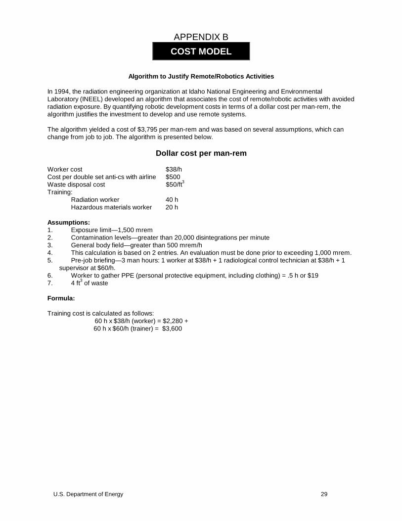
U.S. Department of Energy 29
APPENDIX B
Algorithm to Justify Remote/Robotics Activities
In 1994, the radiation engineering organization at Idaho National Engineering and EnvironmentalLaboratory (INEEL) developed an algorithm that associates the cost of remote/robotic activities with avoidedradiation exposure. By quantifying robotic development costs in terms of a dollar cost per man-rem, thealgorithm justifies the investment to develop and use remote systems.
The algorithm yielded a cost of $3,795 per man-rem and was based on several assumptions, which canchange from job to job. The algorithm is presented below.
Dollar cost per man-rem
Worker cost $38/hCost per double set anti-cs with airline $500Waste disposal cost $50/ft3
Training:Radiation worker 40 hHazardous materials worker 20 h
Assumptions:1. Exposure limit—1,500 mrem2. Contamination levels—greater than 20,000 disintegrations per minute3. General body field—greater than 500 mrem/h4. This calculation is based on 2 entries. An evaluation must be done prior to exceeding 1,000 mrem.5. Pre-job briefing—3 man hours: 1 worker at $38/h + 1 radiological control technician at $38/h + 1
supervisor at $60/h.6. Worker to gather PPE (personal protective equipment, including clothing) = .5 h or $197. 4 ft3 of waste
Formula:
Training cost is calculated as follows:60 h x $38/h (worker) = $2,280 +
60 h x $60/h (trainer) = $3,600
COST MODEL

30 U.S. Department of Energy
Costs are as depicted in the following table:
Type Cost ($)
Worker training 2,280.00
Trainer 3,600.00
Waste disposal 200.00
Pre-job briefing 136.00
Gather PPE 19.00
Double set anti-cs with airlines 500.00
Total Cost 6,735.00
Because the worker can be used to work in other areas, the training cost per man-rem is reduced to theamount indicated in the following table:
Type Cost ($)
Worker 1,140.00
Trainer 1,800.00
Waste disposal 200.00
Pre-job briefing 136.00
Gather PPE 19.00
Double set anti-cs with airlines 500.00
Total Cost 3,795.00

U.S. Department of Energy 31
Note: The cost of anti-cs is based on one 50-ft of airline hose per entry. The cost will increase with additional airline hoses. Cost perairline hose is $200/50 ft.
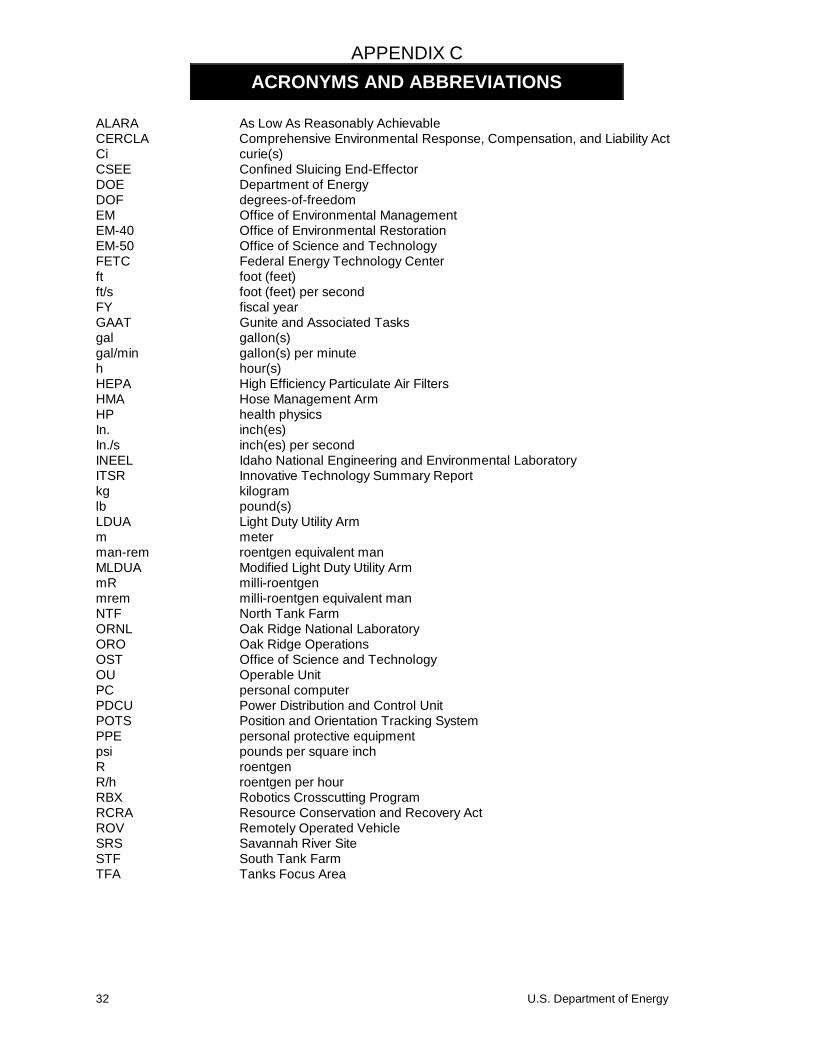
32 U.S. Department of Energy
APPENDIX C
ALARA As Low As Reasonably AchievableCERCLA Comprehensive Environmental Response, Compensation, and Liability ActCi curie(s)CSEE Confined Sluicing End-EffectorDOE Department of EnergyDOF degrees-of-freedomEM Office of Environmental ManagementEM-40 Office of Environmental RestorationEM-50 Office of Science and TechnologyFETC Federal Energy Technology Centerft foot (feet)ft/s foot (feet) per secondFY fiscal yearGAAT Gunite and Associated Tasksgal gallon(s)gal/min gallon(s) per minuteh hour(s)HEPA High Efficiency Particulate Air FiltersHMA Hose Management ArmHP health physicsIn. inch(es)In./s inch(es) per secondINEEL Idaho National Engineering and Environmental LaboratoryITSR Innovative Technology Summary Reportkg kilogramlb pound(s)LDUA Light Duty Utility Armm meterman-rem roentgen equivalent manMLDUA Modified Light Duty Utility ArmmR milli-roentgenmrem milli-roentgen equivalent manNTF North Tank FarmORNL Oak Ridge National LaboratoryORO Oak Ridge OperationsOST Office of Science and TechnologyOU Operable UnitPC personal computerPDCU Power Distribution and Control UnitPOTS Position and Orientation Tracking SystemPPE personal protective equipmentpsi pounds per square inchR roentgenR/h roentgen per hourRBX Robotics Crosscutting ProgramRCRA Resource Conservation and Recovery ActROV Remotely Operated VehicleSRS Savannah River SiteSTF South Tank FarmTFA Tanks Focus Area
ACRONYMS AND ABBREVIATIONS

U.S. Department of Energy 33
TTCTF Tanks Technology Cold Test FacilityTMADS Tether Management and Deployment System