hose and flexible tubing (ms-01-180;rev_12;en-us;catalog)
TRANSCRIPT
Hose and Flexible Tubing 1 HOSE /
FLEXIBLE TUBING
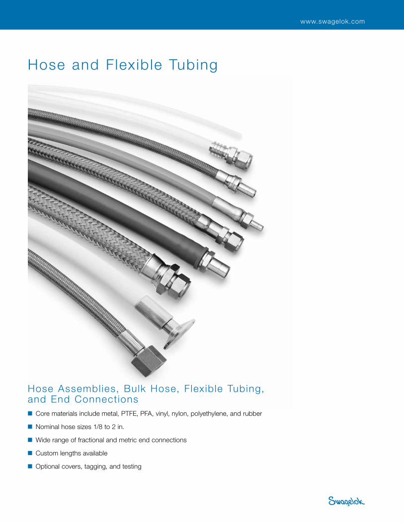
Hose and Flex ib le Tubing
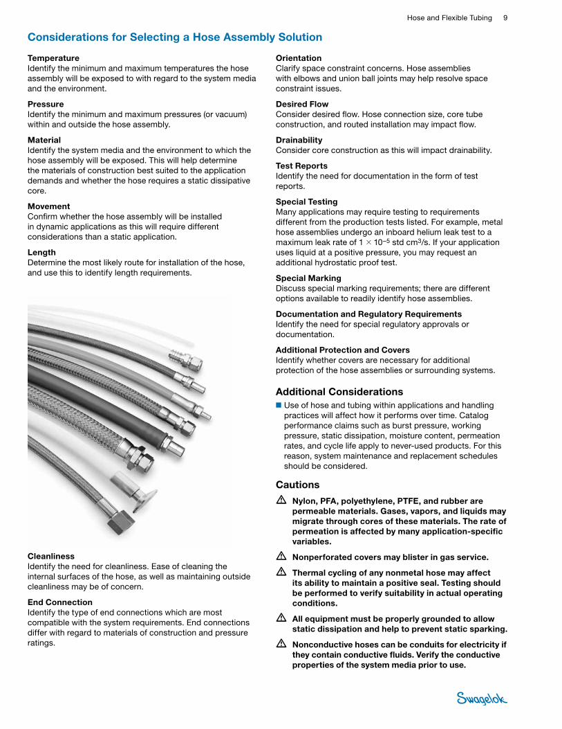
Hose Assembl ies, Bulk Hose, F lex ib le Tubing, and End Connections■ Core materials include metal, PTFE, PFA, vinyl, nylon, polyethylene, and rubber
■ Nominal hose sizes 1/8 to 2 in.
■ Wide range of fractional and metric end connections
■ Custom lengths available
■ Optional covers, tagging, and testing
www.swagelok.com
2 Hose, Quick-Connects, and Sample CylindersHO
SE /
FLEX
IBLE
TU
BING
Swagelok® Hose and Flexible Tubing Nomenclature, 4
Swagelok Hose and Flexible Tubing Selection Guide, 7
Considerations for Selecting a Hose Assembly Solution, 9
Swagelok Hose and Flexible Tubing Installation and Use Guide, 10
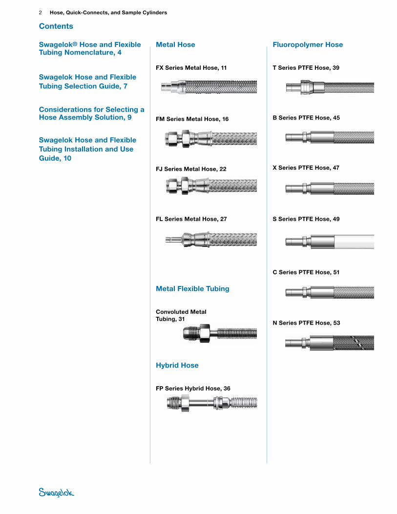
Metal Hose
FX Series Metal Hose, 11
FM Series Metal Hose, 16
FJ Series Metal Hose, 22
FL Series Metal Hose, 27
Metal Flexible Tubing
Convoluted Metal Tubing, 31
Hybrid Hose
FP Series Hybrid Hose, 36
SWAGELOK
SWAGELOK
Contents
Fluoropolymer Hose
T Series PTFE Hose, 39
B Series PTFE Hose, 45
X Series PTFE Hose, 47
S Series PTFE Hose, 49
C Series PTFE Hose, 51
N Series PTFE Hose, 53
Hose and Flexible Tubing 3 HOSE /
FLEXIBLE TUBING
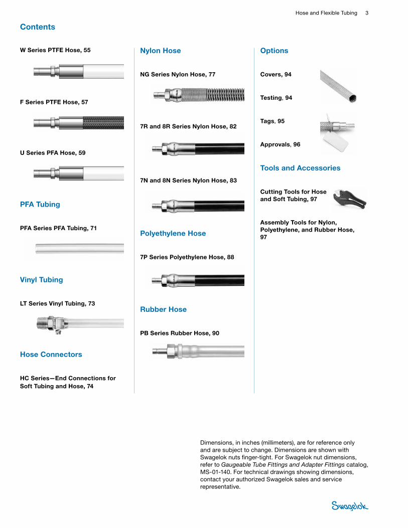
W Series PTFE Hose, 55
F Series PTFE Hose, 57
U Series PFA Hose, 59
PFA Tubing
PFA Series PFA Tubing, 71
Vinyl Tubing
LT Series Vinyl Tubing, 73
Hose Connectors
HC Series—End Connections for Soft Tubing and Hose, 74
Nylon Hose
NG Series Nylon Hose, 77
7R and 8R Series Nylon Hose, 82
7N and 8N Series Nylon Hose, 83
Polyethylene Hose
7P Series Polyethylene Hose, 88
Rubber Hose
PB Series Rubber Hose, 90
Options
Covers, 94
Testing, 94
Tags, 95
Approvals, 96
Tools and Accessories
Cutting Tools for Hose and Soft Tubing, 97
Assembly Tools for Nylon, Polyethylene, and Rubber Hose, 97
Contents
Dimensions, in inches (millimeters), are for reference only and are subject to change. Dimensions are shown with Swagelok nuts finger-tight. For Swagelok nut dimensions, refer to Gaugeable Tube Fittings and Adapter Fittings catalog, MS-01-140. For technical drawings showing dimensions, contact your authorized Swagelok sales and service representative.
4 Hose, Quick-Connects, and Sample CylindersHO
SE /
FLEX
IBLE
TU
BING
SWAGELO
KSWAGELO
K
SWAGELO
K
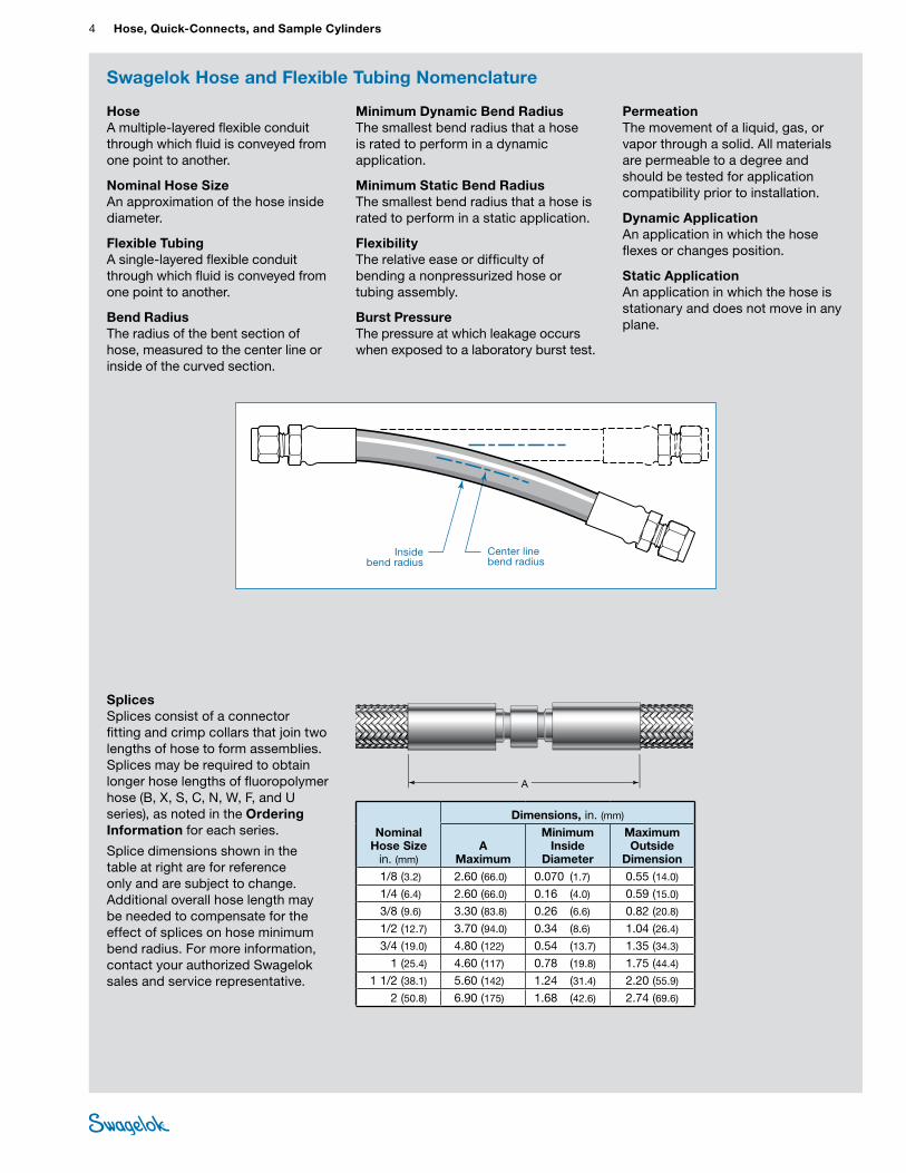
Center line bend radius
Inside bend radius
Minimum Dynamic Bend Radius The smallest bend radius that a hose is rated to perform in a dynamic application.
Minimum Static Bend Radius The smallest bend radius that a hose is rated to perform in a static application.
Flexibility The relative ease or difficulty of bending a nonpressurized hose or tubing assembly.
Burst Pressure The pressure at which leakage occurs when exposed to a laboratory burst test.
Hose A multiple-layered flexible conduit through which fluid is conveyed from one point to another.
Nominal Hose Size An approximation of the hose inside diameter.
Flexible Tubing A single-layered flexible conduit through which fluid is conveyed from one point to another.
Bend Radius The radius of the bent section of hose, measured to the center line or inside of the curved section.
Permeation The movement of a liquid, gas, or vapor through a solid. All materials are permeable to a degree and should be tested for application compatibility prior to installation.
Dynamic Application An application in which the hose flexes or changes position.
Static Application An application in which the hose is stationary and does not move in any plane.
Nominal Hose Size
in. (mm)
Dimensions, in. (mm)
A Maximum
Minimum Inside
Diameter
Maximum Outside
Dimension1/8 (3.2) 2.60 (66.0) 0.070 (1.7) 0.55 (14.0)
1/4 (6.4) 2.60 (66.0) 0.16 (4.0) 0.59 (15.0)
3/8 (9.6) 3.30 (83.8) 0.26 (6.6) 0.82 (20.8)
1/2 (12.7) 3.70 (94.0) 0.34 (8.6) 1.04 (26.4)
3/4 (19.0) 4.80 (122) 0.54 (13.7) 1.35 (34.3)
1 (25.4) 4.60 (117) 0.78 (19.8) 1.75 (44.4)
1 1/2 (38.1) 5.60 (142) 1.24 (31.4) 2.20 (55.9)
2 (50.8) 6.90 (175) 1.68 (42.6) 2.74 (69.6)
CA-PH-1294-DM
A
Swagelok Hose and Flexible Tubing Nomenclature
Splices Splices consist of a connector fitting and crimp collars that join two lengths of hose to form assemblies. Splices may be required to obtain longer hose lengths of fluoropolymer hose (B, X, S, C, N, W, F, and U series), as noted in the Ordering Information for each series.
Splice dimensions shown in the table at right are for reference only and are subject to change. Additional overall hose length may be needed to compensate for the effect of splices on hose minimum bend radius. For more information, contact your authorized Swagelok sales and service representative.
Hose and Flexible Tubing 5 HOSE /
FLEXIBLE TUBING
Swagelok Hose and Flexible Tubing Nomenclature
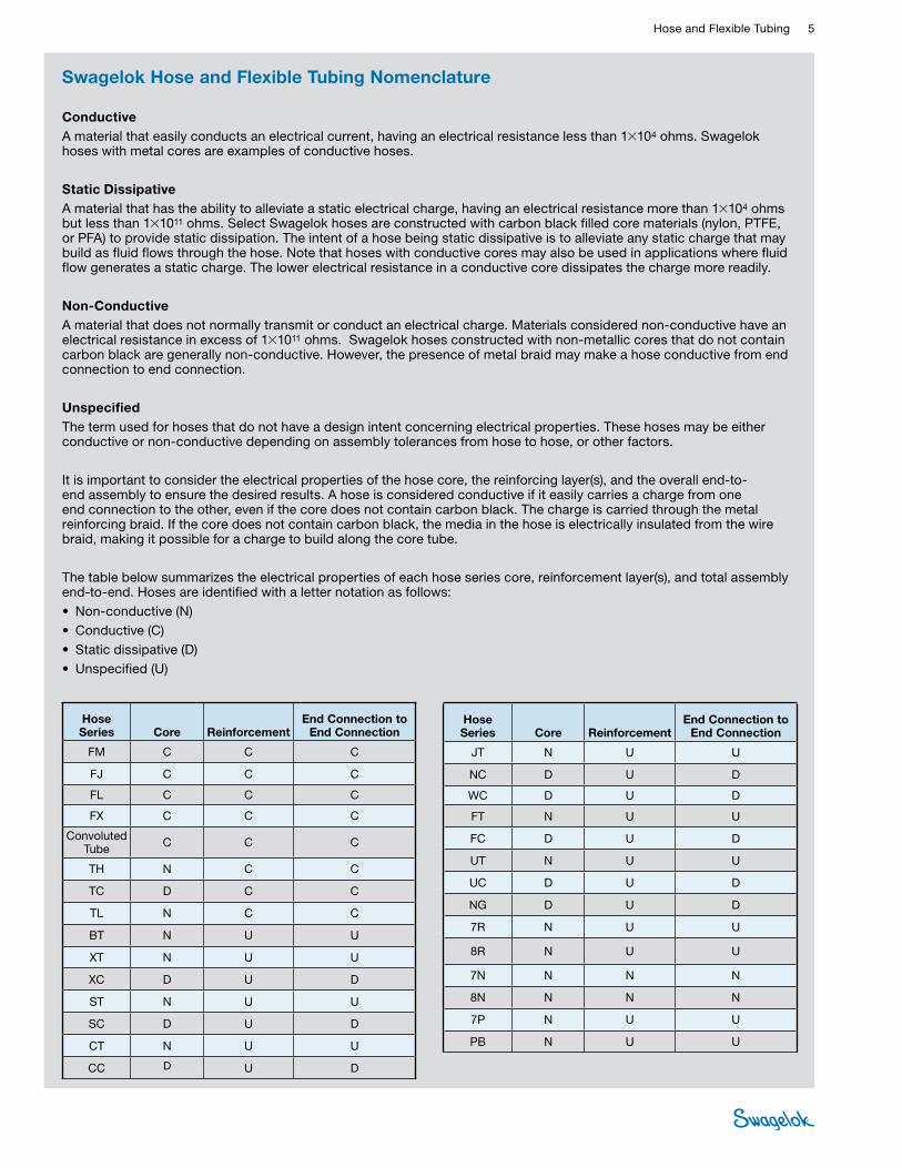
Conductive A material that easily conducts an electrical current, having an electrical resistance less than 1×10⁴ ohms. Swagelok hoses with metal cores are examples of conductive hoses.
Static Dissipative A material that has the ability to alleviate a static electrical charge, having an electrical resistance more than 1×10⁴ ohms but less than 1×10¹¹ ohms. Select Swagelok hoses are constructed with carbon black filled core materials (nylon, PTFE, or PFA) to provide static dissipation. The intent of a hose being static dissipative is to alleviate any static charge that may build as fluid flows through the hose. Note that hoses with conductive cores may also be used in applications where fluid flow generates a static charge. The lower electrical resistance in a conductive core dissipates the charge more readily.
Non-Conductive A material that does not normally transmit or conduct an electrical charge. Materials considered non-conductive have an electrical resistance in excess of 1×10¹¹ ohms. Swagelok hoses constructed with non-metallic cores that do not contain carbon black are generally non-conductive. However, the presence of metal braid may make a hose conductive from end connection to end connection.
Unspecified The term used for hoses that do not have a design intent concerning electrical properties. These hoses may be either conductive or non-conductive depending on assembly tolerances from hose to hose, or other factors.
It is important to consider the electrical properties of the hose core, the reinforcing layer(s), and the overall end-to-end assembly to ensure the desired results. A hose is considered conductive if it easily carries a charge from one end connection to the other, even if the core does not contain carbon black. The charge is carried through the metal reinforcing braid. If the core does not contain carbon black, the media in the hose is electrically insulated from the wire braid, making it possible for a charge to build along the core tube.
The table below summarizes the electrical properties of each hose series core, reinforcement layer(s), and total assembly end-to-end. Hoses are identified with a letter notation as follows:• Non-conductive (N)• Conductive (C)• Static dissipative (D)• Unspecified (U)
Hose Series Core Reinforcement
End Connection to End Connection
FM C C C
FJ C C C
FL C C C
FX C C C
Convoluted Tube C C C
TH N C C
TC D C C
TL N C C
BT N U U
XT N U U
XC D U D
ST N U U
SC D U D
CT N U U
CC D U D
Hose Series Core Reinforcement
End Connection to End Connection
JT N U U
NC D U D
WC D U D
FT N U U
FC D U D
UT N U U
UC D U D
NG D U D
7R N U U
8R N U U
7N N N N
8N N N N
7P N U U
PB N U U
6 Hose, Quick-Connects, and Sample CylindersHO
SE /
FLEX
IBLE
TU
BING
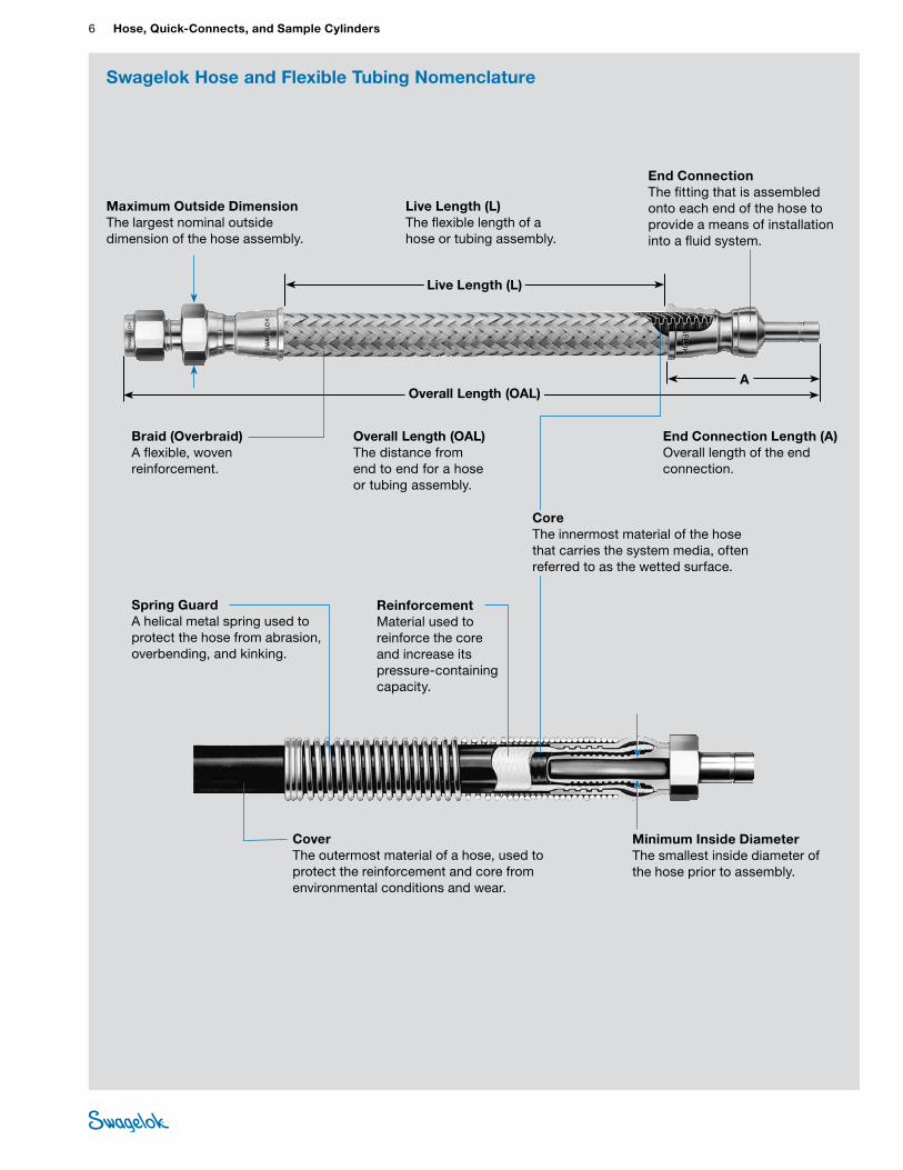
Spring Guard A helical metal spring used to protect the hose from abrasion, overbending, and kinking.
Reinforcement Material used to reinforce the core and increase its pressure-containing capacity.
Minimum Inside Diameter The smallest inside diameter of the hose prior to assembly.
Cover The outermost material of a hose, used to protect the reinforcement and core from environmental conditions and wear.
Braid (Overbraid) A flexible, woven reinforcement.
Maximum Outside Dimension The largest nominal outside dimension of the hose assembly.
End Connection The fitting that is assembled onto each end of the hose to provide a means of installation into a fluid system.
Live Length (L) The flexible length of a hose or tubing assembly.
Live Length (L)
Overall Length (OAL) The distance from end to end for a hose or tubing assembly.
Swagelok Hose and Flexible Tubing Nomenclature
A
End Connection Length (A) Overall length of the end connection.
Core The innermost material of the hose that carries the system media, often referred to as the wetted surface.
Overall Length (OAL)
Hose and Flexible Tubing 7 HOSE /
FLEXIBLE TUBING
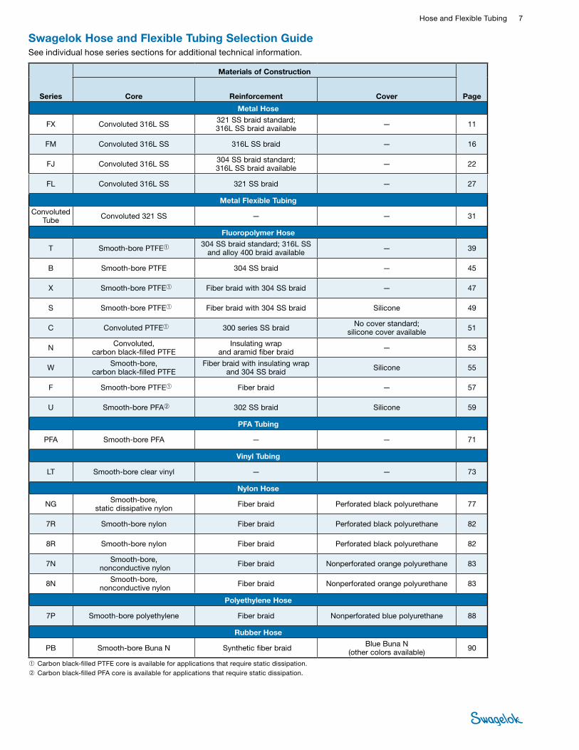
Series
Materials of Construction
PageCore
Reinforcement Cover
Metal Hose
FX Convoluted 316L SS 321 SS braid standard; 316L SS braid available — 11
FM Convoluted 316L SS 316L SS braid — 16
FJ Convoluted 316L SS 304 SS braid standard; 316L SS braid available — 22
FL Convoluted 316L SS 321 SS braid — 27
Metal Flexible TubingConvoluted
Tube Convoluted 321 SS — — 31
Fluoropolymer Hose
T Smooth-bore PTFE➀ 304 SS braid standard; 316L SS and alloy 400 braid available — 39
B Smooth-bore PTFE 304 SS braid — 45
X Smooth-bore PTFE➀ Fiber braid with 304 SS braid — 47
S Smooth-bore PTFE➀ Fiber braid with 304 SS braid Silicone 49
C Convoluted PTFE➀ 300 series SS braid No cover standard; silicone cover available 51
N Convoluted, carbon black-filled PTFE
Insulating wrap and aramid fiber braid — 53
W Smooth-bore, carbon black-filled PTFE
Fiber braid with insulating wrap and 304 SS braid Silicone 55
F Smooth-bore PTFE➀ Fiber braid — 57
U Smooth-bore PFA➁ 302 SS braid Silicone 59
PFA Tubing
PFA Smooth-bore PFA — — 71
Vinyl Tubing
LT Smooth-bore clear vinyl — — 73
Nylon Hose
NG Smooth-bore, static dissipative nylon Fiber braid Perforated black polyurethane 77
7R Smooth-bore nylon Fiber braid Perforated black polyurethane 82
8R Smooth-bore nylon Fiber braid Perforated black polyurethane 82
7N Smooth-bore, nonconductive nylon Fiber braid Nonperforated orange polyurethane 83
8N Smooth-bore, nonconductive nylon Fiber braid Nonperforated orange polyurethane 83
Polyethylene Hose
7P Smooth-bore polyethylene Fiber braid Nonperforated blue polyurethane 88
Rubber Hose
PB Smooth-bore Buna N Synthetic fiber braid Blue Buna N (other colors available) 90
Swagelok Hose and Flexible Tubing Selection GuideSee individual hose series sections for additional technical information.
➀ Carbon black-filled PTFE core is available for applications that require static dissipation.➁ Carbon black-filled PFA core is available for applications that require static dissipation.
8 Hose, Quick-Connects, and Sample CylindersHO
SE /
FLEX
IBLE
TU
BING
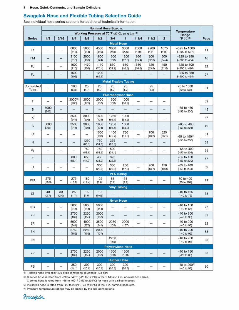
Swagelok Hose and Flexible Tubing Selection GuideSee individual hose series sections for additional technical information.
Series
Nominal Hose Size, in.Temperature
Range °F (°C)④ Page
Working Pressure at 70°F (20°C), psig (bar)④
1/8 3/16 1/4 3/8 1/2 3/4 1 1 1/4 1 1/2 2
Metal Hose
FX — — 6000 (413)
5000 (344)
4500 (310)
3600 (248)
3000 (206)
2600 (179)
2200 (151)
1675 (115)
−325 to 1000 (−200 to 537)
11
FM — — 3100 (213)
2000 (137)
1800 (124)
1500 (103)
1200 (82.6)
950 (65.4)
900 (62.0)
500 (34.4)
−325 to 850 (−200 to 454)
16
FJ — — 1600 (110)
1470 (101)
1110 (76.4)
860 (59.2)
680 (46.8)
680 (46.8)
520 (35.8)
450 (31.0)
−325 to 800 (−200 to 426)
22
FL — — 1500 (103)
— 1200 (82.6)
— — — — — −325 to 850 (−200 to 454)
27
Metal Flexible TubingConvoluted
Tube — — 100 (6.8)
25 (1.7)
25 (1.7)
25 (1.7)
25 (1.7)
— 25 (1.7)
— 70 to 1000 (20 to 537)
31
Fluoropolymer Hose
T — — 3000➀ (206)
2500 (172)
2000 (137)
1500 (103)
1000 (68.9)
— — —
−65 to 450 (−53 to 230)
39
B 3000 (206)
— — — — — — — — — 45
X — — 3500 (241)
3000 (206)
1800 (124)
1250 (86.1)
1000 (68.9)
— — — 47
S 3000 (206)
— 3500 (241)
3000 (206)
1800 (124)
1250 (86.1)
1000 (68.9)
— — — −65 to 400 (−53 to 204)
49
C — — — — 1500 (103)
1100 (75.7)
750 (51.6)
— 700 (48.2)
525 (36.1) −65 to 450➁
(−53 to 230)
51
N — — — 1250 (86.1)
750 (51.6)
375 (25.8)
— — — — 53
W — — — 750 (51.6)
750 (51.6)
500 (34.4)
— — — — −65 to 400 (−53 to 204)
55
F — — 800 (55.1)
650 (44.7)
450 (31.0)
325 (22.3)
— — — — −65 to 450 (−53 to 230)
57
U — — — — 300 (20.6)
300 (20.6)
250 (17.2)
— 200 (13.7)
150 (10.3)
–65 to 400 (–53 to 204)
59
PFA Tubing
PFA 275 (18.9)
— 275 (18.9)
180 (12.4)
125 (8.6)
83 (5.7)
61 (4.2)
— — — 70 to 400 (20 to 204)
71
Vinyl Tubing
LT 40 (2.7)
30 (2.0)
25 (1.7)
15 (1.0)
10 (0.68)
— — — — — −40 to 165 (−40 to 73)
73
Nylon Hose
NG — — 5000 (344)
5000 (344)
5000 (344)
— — — — — −40 to 150 (−40 to 65)
77
7R — — 2750 (189)
2250 (155)
2000 (137)
— — — — — −40 to 200 (−40 to 93)
82
8R — — 5000 (344)
4000 (275)
3500 (241)
2250 (155)
2000 (137)
— — — −40 to 200 (−40 to 93)
82
7N — — 2750 (189)
2250 (155)
2000 (137)
— — — — — −40 to 200 (−40 to 93)
83
8N — — — — — 2250 (155)
— — — — −40 to 200 (−40 to 93)
83
Polyethylene Hose
7P — — 2750 (189)
2250 (155)
2000 (137)
1500 (103)
1500 (103)
— — — −10 to 150 (−23 to 65)
88
Rubber Hose
PB — — 350 (24.1)
300 (20.6)
300 (20.6)
300 (20.6)
300 (20.6)
— — — −40 to 200➂ (−40 to 93)
90
➀ T series hose with alloy 400 braid is rated to 1500 psig (103 bar).
➁ C series hose is rated from −20 to 340°F (−28 to 171°C) in the 1 1/2 and 2 in. nominal hose sizes. C series hose is rated from −65 to 400°F (−53 to 204°C) for hose with a silicone cover.
➂PB series hose is rated from −20 to 200°F (−28 to 93°C) in the 1 in. nominal hose size.➃Pressure-temperature ratings may be limited by the end connections.
Hose and Flexible Tubing 9 HOSE /
FLEXIBLE TUBING
Temperature Identify the minimum and maximum temperatures the hose assembly will be exposed to with regard to the system media and the environment.
Pressure Identify the minimum and maximum pressures (or vacuum) within and outside the hose assembly.
Material Identify the system media and the environment to which the hose assembly will be exposed. This will help determine the materials of construction best suited to the application demands and whether the hose requires a static dissipative core.
Movement Confirm whether the hose assembly will be installed in dynamic applications as this will require different considerations than a static application.
Length Determine the most likely route for installation of the hose, and use this to identify length requirements.
Cleanliness Identify the need for cleanliness. Ease of cleaning the internal surfaces of the hose, as well as maintaining outside cleanliness may be of concern.
End Connection Identify the type of end connections which are most compatible with the system requirements. End connections differ with regard to materials of construction and pressure ratings.
Considerations for Selecting a Hose Assembly Solution
Orientation Clarify space constraint concerns. Hose assemblies with elbows and union ball joints may help resolve space constraint issues.
Desired Flow Consider desired flow. Hose connection size, core tube construction, and routed installation may impact flow.
Drainability Consider core construction as this will impact drainability.
Test Reports Identify the need for documentation in the form of test reports.
Special Testing Many applications may require testing to requirements different from the production tests listed. For example, metal hose assemblies undergo an inboard helium leak test to a maximum leak rate of 1 × 10⁻⁵ std cm3/s. If your application uses liquid at a positive pressure, you may request an additional hydrostatic proof test.
Special Marking Discuss special marking requirements; there are different options available to readily identify hose assemblies.
Documentation and Regulatory Requirements Identify the need for special regulatory approvals or documentation.
Additional Protection and Covers Identify whether covers are necessary for additional protection of the hose assemblies or surrounding systems.
Additional Considerations■Use of hose and tubing within applications and handling
practices will affect how it performs over time. Catalog performance claims such as burst pressure, working pressure, static dissipation, moisture content, permeation rates, and cycle life apply to never-used products. For this reason, system maintenance and replacement schedules should be considered.
Cautions
• Nylon, PFA, polyethylene, PTFE, and rubber are permeable materials. Gases, vapors, and liquids may migrate through cores of these materials. The rate of permeation is affected by many application-specific variables.
• Nonperforated covers may blister in gas service.
• Thermal cycling of any nonmetal hose may affect its ability to maintain a positive seal. Testing should be performed to verify suitability in actual operating conditions.
• All equipment must be properly grounded to allow static dissipation and help to prevent static sparking.
• Nonconductive hoses can be conduits for electricity if they contain conductive fluids. Verify the conductive properties of the system media prior to use.
10 Hose, Quick-Connects, and Sample CylindersHO
SE /
FLEX
IBLE
TU
BING
Swagelok Hose and Flexible Tubing Installation and Use Guide
Inspection Establish an inspection schedule based on system application and replacement history.
Electrostatic Discharge Static electricity can be generated by fluid passing through the hose. Select hose with sufficient conductivity to ground the static electric charge and allow static dissipation. If static electricity generation is possible within an application, choose static dissipative hose and properly ground to earth.
Vibration Evaluate amount of system vibration when selecting hose. Metal hose may not be appropriate for systems with constant or severe vibration.
Length Take into consideration hose movement, system pressurization, and thermal expansion when determining hose length. Installing hose that does not have sufficient length to accommodate these factors may reduce hose life.
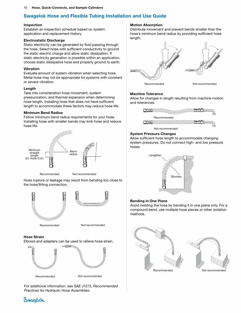
Minimum Bend Radius Follow minimum bend radius requirements for your hose. Installing hose with smaller bends may kink hose and reduce hose life.
Hose rupture or leakage may result from bending too close to the hose/fitting connection.
Hose Strain Elbows and adapters can be used to relieve hose strain.
Motion Absorption Distribute movement and prevent bends smaller than the hose’s minimum bend radius by providing sufficient hose length.
Machine Tolerance Allow for changes in length resulting from machine motion and tolerances.
System Pressure Changes Allow sufficient hose length to accommodate changing system pressures. Do not connect high- and low pressure hoses
For additional information, see SAE J1273, Recommended Practices for Hydraulic Hose Assemblies.
stainless motion absorption
Recommended Not recommended
stainless machine pressure changes
stainless bending in one plane
Stainless hose strain
stainless minimum bend radius
Bend radius
Minimum straight length
(2x Hose O.D.)
Stainless system pressure changes
Lengthen
ShortenRecommended Not recommended
Recommended
Recommended Not recommended
Recommended
Not recommended
Recommended Not recommended
Not recommended
Bending in One Plane Avoid twisting the hose by bending it in one plane only. For a compound bend, use multiple hose pieces or other isolation methods.
Hose and Flexible Tubing 11 HOSE /
FLEXIBLE TUBING
FX Series Metal Hose
Technical Data
Nominal Hose Size
in. (mm)
Inside Diameter in. (mm)
Outside Diameter in. (mm)
Minimum Center Line Bend Radius
in. (cm) Temperature
Range °F (°C)
Working Pressure at
–325 to 100°F (–200 to 37°C) Vacuum to ...
psig (bar)
Minimum Burst
Pressure at 70°F (20°C)
psig (bar)
Bulk Hose
Weightlb/ft (kg/m)Static Dynamic
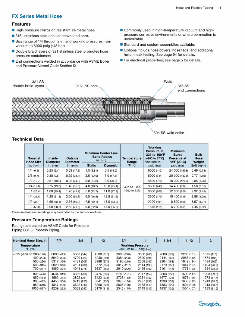
1/4 (6.4) 0.25 (6.4) 0.68 (17.3) 1.5 (3.81) 5.5 (14.0)
–325 to 1000 (–200 to 537)
6000 (413) 24 000 (1653) 0.49 (0.73)
3/8 (9.7) 0.38 (9.5) 0.92 (23.4) 2.5 (6.40) 7.0 (17.8) 5000 (344) 20 000 (1378) 0.77 (1.15)
1/2 (12.7) 0.51 (13.0) 0.98 (24.9) 3.0 (7.62) 8.0 (20.3) 4500 (310) 18 000 (1240) 0.85 (1.26)
3/4 (19.0) 0.75 (19.0) 1.40 (35.6) 4.0 (10.2) 10.0 (25.4) 3600 (248) 14 400 (992) 1.58 (2.35)
1 (25.4) 1.00 (25.4) 1.70 (43.2) 5.0 (12.7) 11.0 (27.9) 3000 (206) 12 000 (826) 2.32 (3.45)
1 1/4 (31.8) 1.25 (31.8) 2.00 (50.8) 6.5 (16.5) 12.5 (31.8) 2600 (179) 10 400 (716) 2.88 (4.29)
1 1/2 (38.1) 1.50 (38.1) 2.36 (59.9) 7.5 (19.1) 13.0 (33.0) 2200 (151) 8 800 (606) 3.57 (5.31)
2 (50.8) 2.00 (50.8) 2.82 (71.6) 9.0 (22.9) 14.0 (35.6) 1675 (115) 6 700 (461) 4.45 (6.62)
321 SS double-braid layers 316L SS core 316 SS
end connections
Features■High-pressure corrosion resistant all-metal hose.
■316L stainless steel annular convoluted core.
■Size range of 1/4 through 2 in. and working pressures from vacuum to 6000 psig (413 bar).
■Double braid layers of 321 stainless steel promotes hose pressure containment.
■End connections welded in accordance with ASME Boiler and Pressure Vessel Code Section IX.
■Commonly used in high-temperature vacuum and high-pressure corrosive environments or where permeation is undesirable.
■Standard and custom assemblies available.
■Options include hose covers, hose tags, and additional helium leak testing. See page 94 for details.
■For electrical properties, see page 5 for details.
Weld
Nominal Hose Size, in. 1/4 3/8 1/2 3/4 1 1 1/4 1 1/2 2
Temperature °F (°C)
Working Pressure Vacuum to ... psig (bar)
–325 (–200) to 300 (148)400 (204) 500 (260) 600 (315) 700 (371)
6000 (413) 5640 (388)5317 (366)5029 (346)4850 (334)
5000 (344)4700 (323)4431 (305)4191 (288)4041 (278)
4500 (310) 4230 (291)3988 (274)3772 (259)3637 (250)
3600 (248)3384 (233)3190 (219)3017 (207)2910 (200)
3000 (206)2820 (194)2658 (183)2514 (193)2425 (167)
2600 (179)2444 (168)2304 (158)2179 (150)2101 (144)
2200 (151)2068 (142)1949 (134)1844 (127)1778 (122)
1675 (115) 1574 (108)1484 (102)1404 (96.7)1354 (93.2)
800 (426) 850 (454) 900 (482) 950 (510)
1000 (537)
4634 (319)4562 (314)4455 (306)4347 (299)4239 (292)
3862 (266)3802 (261)3712 (255)3622 (249)3532 (243)
3476 (239)3422 (235)3341 (230)3260 (224)3179 (219)
2780 (191)2737 (188)2673 (184)2608 (179)2543 (175)
2317 (159)2281 (157)2227 (153)2173 (149)2119 (145)
2008 (138)1977 (136)1930 (132)1883 (129)1837 (126)
1699 (117)1673 (115)1633 (112)1594 (109)1554 (107)
1293 (89.0)1273 (87.7)1243 (85.6)1213 (83.5)1183 (81.5)
Pressure-Temperature RatingsRatings are based on ASME Code for Pressure Piping B31.3, Process Piping.
304 SS weld collar
Pressure-temperature ratings may be limited by the end connections.
12 Hose, Quick-Connects, and Sample CylindersHO
SE /
FLEX
IBLE
TU
BING
FX Series Metal Hose
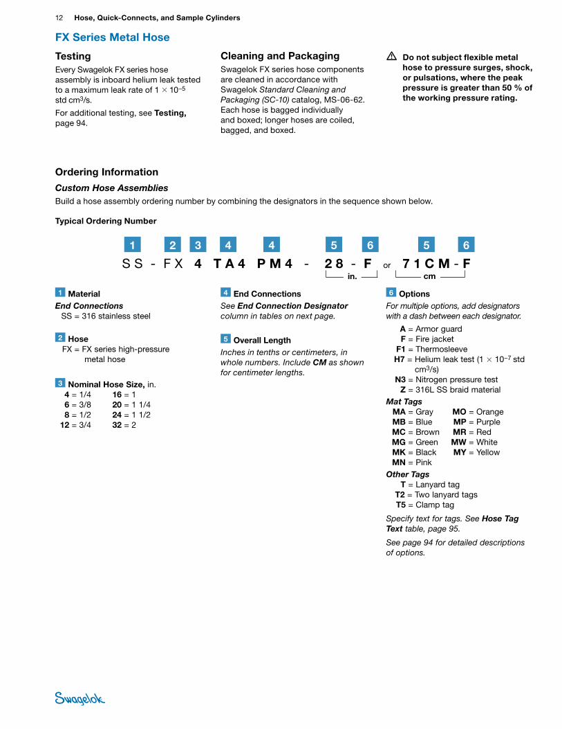
1 MaterialEnd Connections SS = 316 stainless steel
2 Hose FX = FX series high-pressure
metal hose
6 OptionsFor multiple options, add designators with a dash between each designator.
A = Armor guard F = Fire jacket F1 = Thermosleeve H7 = Helium leak test (1 × 10⁻⁷ std
cm3/s) N3 = Nitrogen pressure test Z = 316L SS braid materialMat Tags MA = Gray MO = Orange MB = Blue MP = Purple MC = Brown MR = Red MG = Green MW = White MK = Black MY = Yellow MN = PinkOther Tags T = Lanyard tag T2 = Two lanyard tags T5 = Clamp tag
Specify text for tags. See Hose Tag Text table, page 95.
See page 94 for detailed descriptions of options.
3 Nominal Hose Size, in. 4 = 1/4 6 = 3/8 8 = 1/2 12 = 3/4
16 = 1 20 = 1 1/4 24 = 1 1/2 32 = 2
4 End ConnectionsSee End Connection Designator column in tables on next page.
Typical Ordering Number
5 Overall LengthInches in tenths or centimeters, in whole numbers. Include CM as shown for centimeter lengths.
Ordering Information
Custom Hose Assemblies Build a hose assembly ordering number by combining the designators in the sequence shown below.
S S - F X 4 T A 4 P M 4 - 2 8 - F or 7 1 C M - F2 61 3 44 5 65
in. cm
TestingEvery Swagelok FX series hose assembly is inboard helium leak tested to a maximum leak rate of 1 × 10⁻⁵ std cm3/s.
For additional testing, see Testing, page 94.
• Do not subject flexible metal hose to pressure surges, shock, or pulsations, where the peak pressure is greater than 50 % of the working pressure rating.
Cleaning and PackagingSwagelok FX series hose components are cleaned in accordance with Swagelok Standard Cleaning and Packaging (SC‑10) catalog, MS-06-62. Each hose is bagged individually and boxed; longer hoses are coiled, bagged, and boxed.
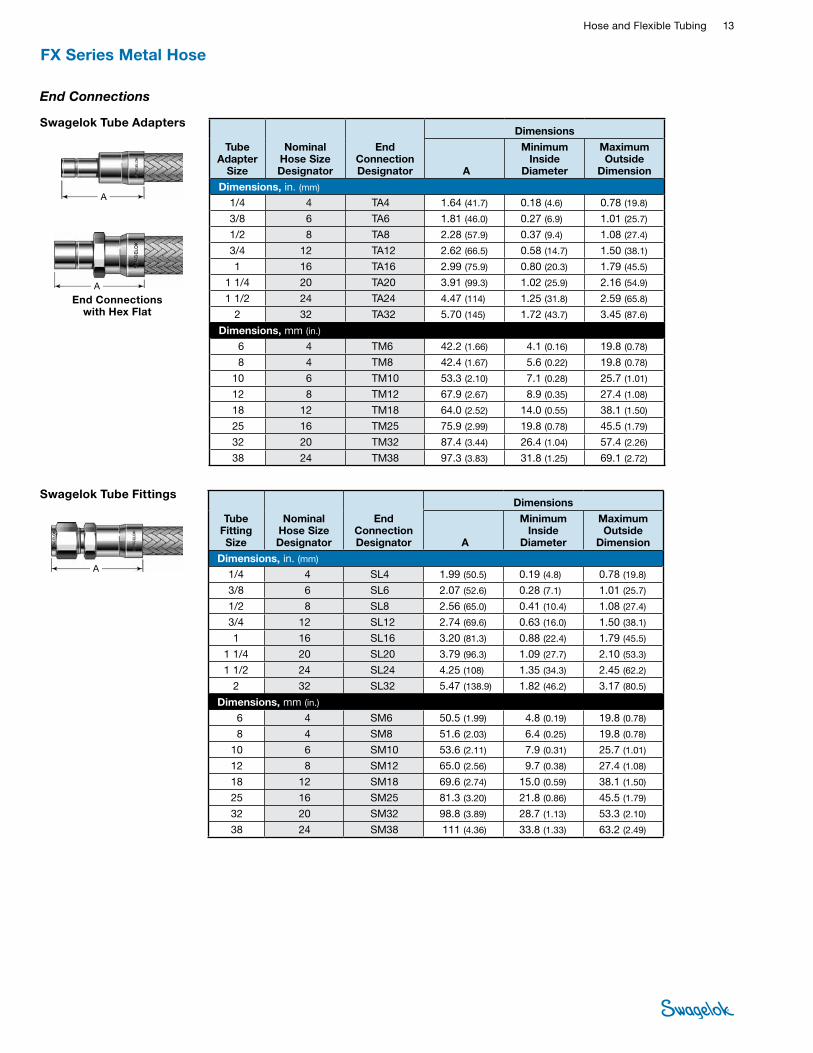
Hose and Flexible Tubing 13 HOSE /
FLEXIBLE TUBING
A
Swagelok Tube Adapters
A
Tube Adapter
Size
Nominal Hose Size Designator
End Connection Designator
Dimensions
A
Minimum Inside
Diameter
Maximum Outside
Dimension
Dimensions, in. (mm)
1/4 4 TA4 1.64 (41.7) 0.18 (4.6) 0.78 (19.8)
3/8 6 TA6 1.81 (46.0) 0.27 (6.9) 1.01 (25.7)
1/2 8 TA8 2.28 (57.9) 0.37 (9.4) 1.08 (27.4)
3/4 12 TA12 2.62 (66.5) 0.58 (14.7) 1.50 (38.1)
1 16 TA16 2.99 (75.9) 0.80 (20.3) 1.79 (45.5)
1 1/4 20 TA20 3.91 (99.3) 1.02 (25.9) 2.16 (54.9)
1 1/2 24 TA24 4.47 (114) 1.25 (31.8) 2.59 (65.8)
2 32 TA32 5.70 (145) 1.72 (43.7) 3.45 (87.6)
Dimensions, mm (in.) 6 4 TM6 42.2 (1.66) 4.1 (0.16) 19.8 (0.78)
8 4 TM8 42.4 (1.67) 5.6 (0.22) 19.8 (0.78)
10 6 TM10 53.3 (2.10) 7.1 (0.28) 25.7 (1.01)
12 8 TM12 67.9 (2.67) 8.9 (0.35) 27.4 (1.08)
18 12 TM18 64.0 (2.52) 14.0 (0.55) 38.1 (1.50)
25 16 TM25 75.9 (2.99) 19.8 (0.78) 45.5 (1.79)
32 20 TM32 87.4 (3.44) 26.4 (1.04) 57.4 (2.26)
38 24 TM38 97.3 (3.83) 31.8 (1.25) 69.1 (2.72)
End Connections with Hex Flat
End Connections
Swagelok Tube Fittings
A
Tube Fitting Size
Nominal Hose Size Designator
End Connection Designator
Dimensions
A
Minimum Inside
Diameter
Maximum Outside
Dimension
Dimensions, in. (mm)
1/4 4 SL4 1.99 (50.5) 0.19 (4.8) 0.78 (19.8)
3/8 6 SL6 2.07 (52.6) 0.28 (7.1) 1.01 (25.7)
1/2 8 SL8 2.56 (65.0) 0.41 (10.4) 1.08 (27.4)
3/4 12 SL12 2.74 (69.6) 0.63 (16.0) 1.50 (38.1)
1 16 SL16 3.20 (81.3) 0.88 (22.4) 1.79 (45.5)
1 1/4 20 SL20 3.79 (96.3) 1.09 (27.7) 2.10 (53.3)
1 1/2 24 SL24 4.25 (108) 1.35 (34.3) 2.45 (62.2)
2 32 SL32 5.47 (138.9) 1.82 (46.2) 3.17 (80.5)
Dimensions, mm (in.) 6 4 SM6 50.5 (1.99) 4.8 (0.19) 19.8 (0.78)
8 4 SM8 51.6 (2.03) 6.4 (0.25) 19.8 (0.78)
10 6 SM10 53.6 (2.11) 7.9 (0.31) 25.7 (1.01)
12 8 SM12 65.0 (2.56) 9.7 (0.38) 27.4 (1.08)
18 12 SM18 69.6 (2.74) 15.0 (0.59) 38.1 (1.50)
25 16 SM25 81.3 (3.20) 21.8 (0.86) 45.5 (1.79)
32 20 SM32 98.8 (3.89) 28.7 (1.13) 53.3 (2.10)
38 24 SM38 111 (4.36) 33.8 (1.33) 63.2 (2.49)
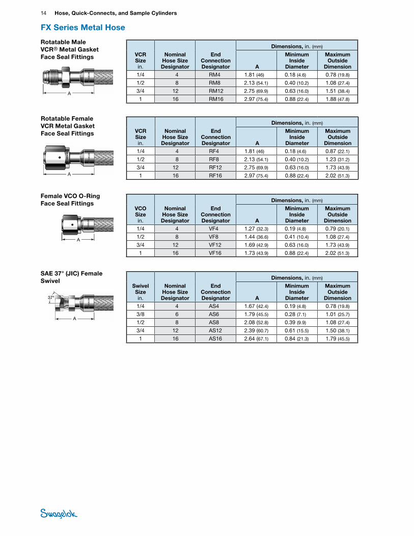
FX Series Metal Hose
14 Hose, Quick-Connects, and Sample CylindersHO
SE /
FLEX
IBLE
TU
BING
FX Series Metal Hose
Female VCO O-Ring Face Seal Fittings
A
VCO Size in.
Nominal Hose Size Designator
End Connection Designator
Dimensions, in. (mm)
A
Minimum Inside
Diameter
Maximum Outside
Dimension 1/4 4 VF4 1.27 (32.3) 0.19 (4.8) 0.79 (20.1)
1/2 8 VF8 1.44 (36.6) 0.41 (10.4) 1.08 (27.4)
3/4 12 VF12 1.69 (42.9) 0.63 (16.0) 1.73 (43.9)
1 16 VF16 1.73 (43.9) 0.88 (22.4) 2.02 (51.3)
Rotatable Male VCR® Metal Gasket Face Seal Fittings VCR
Size in.
Nominal Hose Size Designator
End Connection Designator
Dimensions, in. (mm)
A
Minimum Inside
Diameter
Maximum Outside
Dimension1/4 4 RM4 1.81 (46) 0.18 (4.6) 0.78 (19.8)
1/2 8 RM8 2.13 (54.1) 0.40 (10.2) 1.08 (27.4)
3/4 12 RM12 2.75 (69.9) 0.63 (16.0) 1.51 (38.4)
1 16 RM16 2.97 (75.4) 0.88 (22.4) 1.88 (47.8)
Rotatable Female VCR Metal Gasket Face Seal Fittings
A
VCR Size in.
Nominal Hose Size Designator
End Connection Designator
Dimensions, in. (mm)
A
Minimum Inside
Diameter
Maximum Outside
Dimension1/4 4 RF4 1.81 (46) 0.18 (4.6) 0.87 (22.1)
1/2 8 RF8 2.13 (54.1) 0.40 (10.2) 1.23 (31.2)
3/4 12 RF12 2.75 (69.9) 0.63 (16.0) 1.73 (43.9)
1 16 RF16 2.97 (75.4) 0.88 (22.4) 2.02 (51.3)
SAE 37° (JIC) Female Swivel
A
Swivel Size in.
Nominal Hose Size Designator
End Connection Designator
Dimensions, in. (mm)
A
Minimum Inside
Diameter
Maximum Outside
Dimension 1/4 4 AS4 1.67 (42.4) 0.19 (4.8) 0.78 (19.8)
3/8 6 AS6 1.79 (45.5) 0.28 (7.1) 1.01 (25.7)
1/2 8 AS8 2.08 (52.8) 0.39 (9.9) 1.08 (27.4)
3/4 12 AS12 2.39 (60.7) 0.61 (15.5) 1.50 (38.1)
1 16 AS16 2.64 (67.1) 0.84 (21.3) 1.79 (45.5)
A
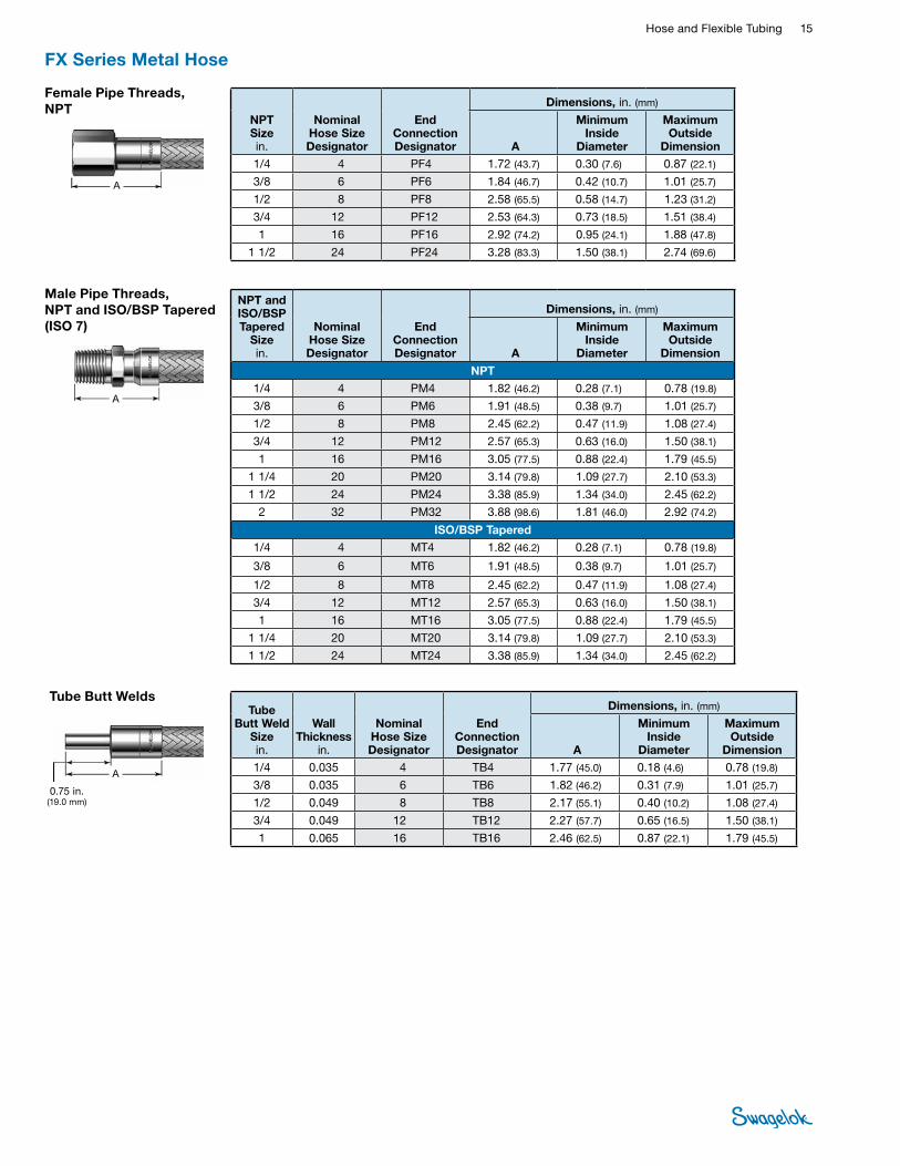
Hose and Flexible Tubing 15 HOSE /
FLEXIBLE TUBING
Female Pipe Threads, NPT
A
NPT Size in.
Nominal Hose Size Designator
End Connection Designator
Dimensions, in. (mm)
A
Minimum Inside
Diameter
Maximum Outside
Dimension 1/4 4 PF4 1.72 (43.7) 0.30 (7.6) 0.87 (22.1)
3/8 6 PF6 1.84 (46.7) 0.42 (10.7) 1.01 (25.7)
1/2 8 PF8 2.58 (65.5) 0.58 (14.7) 1.23 (31.2)
3/4 12 PF12 2.53 (64.3) 0.73 (18.5) 1.51 (38.4)
1 16 PF16 2.92 (74.2) 0.95 (24.1) 1.88 (47.8)
1 1/2 24 PF24 3.28 (83.3) 1.50 (38.1) 2.74 (69.6)
FX Series Metal Hose
Tube Butt Weld
Size in.
Wall Thickness
in.
Nominal Hose Size Designator
End Connection Designator
Dimensions, in. (mm)
A
Minimum Inside
Diameter
Maximum Outside
Dimension1/4 0.035 4 TB4 1.77 (45.0) 0.18 (4.6) 0.78 (19.8)
3/8 0.035 6 TB6 1.82 (46.2) 0.31 (7.9) 1.01 (25.7)
1/2 0.049 8 TB8 2.17 (55.1) 0.40 (10.2) 1.08 (27.4)
3/4 0.049 12 TB12 2.27 (57.7) 0.65 (16.5) 1.50 (38.1)
1 0.065 16 TB16 2.46 (62.5) 0.87 (22.1) 1.79 (45.5)
Tube Butt Welds
A
0.75 in. (19.0 mm)
Male Pipe Threads, NPT and ISO/BSP Tapered (ISO 7)
NPT and ISO/BSP Tapered
Size in.
Nominal Hose Size Designator
End Connection Designator
Dimensions, in. (mm)
A
Minimum Inside
Diameter
Maximum Outside
Dimension
NPT1/4 4 PM4 1.82 (46.2) 0.28 (7.1) 0.78 (19.8)
3/8 6 PM6 1.91 (48.5) 0.38 (9.7) 1.01 (25.7)
1/2 8 PM8 2.45 (62.2) 0.47 (11.9) 1.08 (27.4)
3/4 12 PM12 2.57 (65.3) 0.63 (16.0) 1.50 (38.1)
1 16 PM16 3.05 (77.5) 0.88 (22.4) 1.79 (45.5)
1 1/4 20 PM20 3.14 (79.8) 1.09 (27.7) 2.10 (53.3)
1 1/2 24 PM24 3.38 (85.9) 1.34 (34.0) 2.45 (62.2)
2 32 PM32 3.88 (98.6) 1.81 (46.0) 2.92 (74.2)
ISO/BSP Tapered1/4 4 MT4 1.82 (46.2) 0.28 (7.1) 0.78 (19.8)
3/8 6 MT6 1.91 (48.5) 0.38 (9.7) 1.01 (25.7)
1/2 8 MT8 2.45 (62.2) 0.47 (11.9) 1.08 (27.4)
3/4 12 MT12 2.57 (65.3) 0.63 (16.0) 1.50 (38.1)
1 16 MT16 3.05 (77.5) 0.88 (22.4) 1.79 (45.5)
1 1/4 20 MT20 3.14 (79.8) 1.09 (27.7) 2.10 (53.3)
1 1/2 24 MT24 3.38 (85.9) 1.34 (34.0) 2.45 (62.2)
A
16 Hose, Quick-Connects, and Sample CylindersHO
SE /
FLEX
IBLE
TU
BING
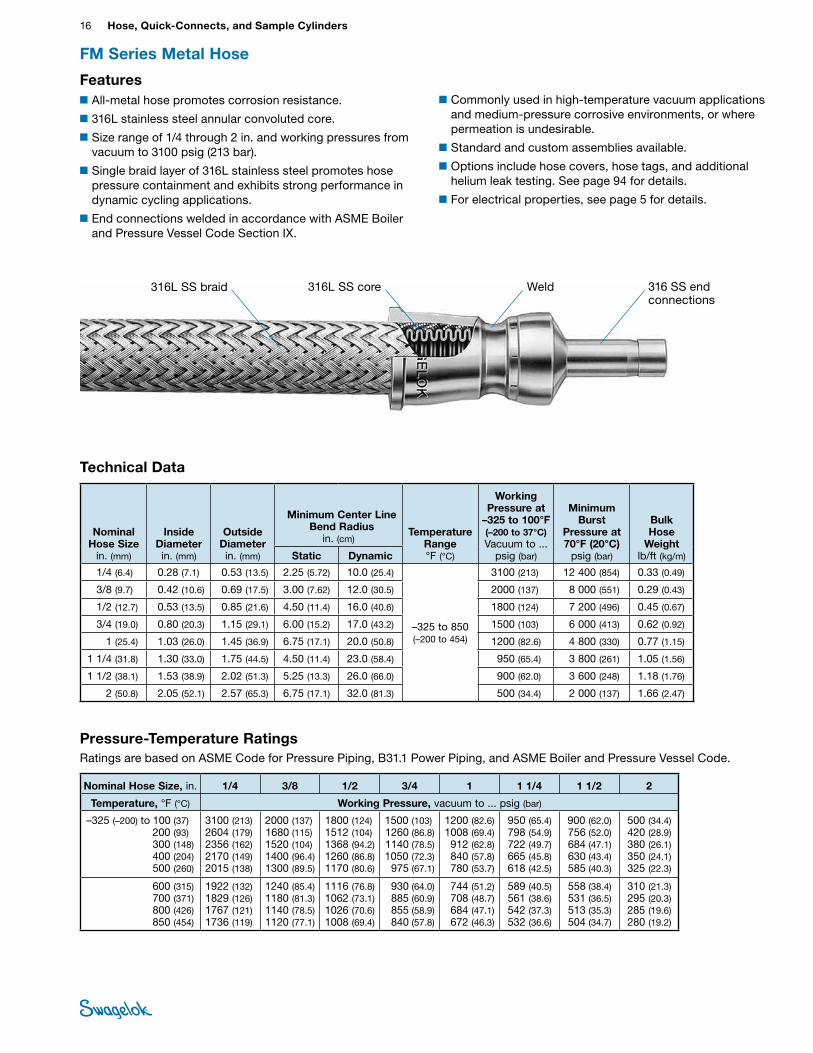
■All-metal hose promotes corrosion resistance.
■316L stainless steel annular convoluted core.
■Size range of 1/4 through 2 in. and working pressures from vacuum to 3100 psig (213 bar).
■Single braid layer of 316L stainless steel promotes hose pressure containment and exhibits strong performance in dynamic cycling applications.
■End connections welded in accordance with ASME Boiler and Pressure Vessel Code Section IX.
■Commonly used in high-temperature vacuum applications and medium-pressure corrosive environments, or where permeation is undesirable.
■Standard and custom assemblies available.
■Options include hose covers, hose tags, and additional helium leak testing. See page 94 for details.
■For electrical properties, see page 5 for details.
Technical Data
FM Series Metal Hose
Nominal Hose Size
in. (mm)
Inside Diameter in. (mm)
Outside Diameter in. (mm)
Minimum Center Line Bend Radius
in. (cm) Temperature
Range °F (°C)
Working Pressure at
–325 to 100°F (–200 to 37°C) Vacuum to ...
psig (bar)
Minimum Burst
Pressure at 70°F (20°C)
psig (bar)
Bulk Hose
Weightlb/ft (kg/m)Static Dynamic
1/4 (6.4) 0.28 (7.1) 0.53 (13.5) 2.25 (5.72) 10.0 (25.4)
–325 to 850 (–200 to 454)
3100 (213) 12 400 (854) 0.33 (0.49)
3/8 (9.7) 0.42 (10.6) 0.69 (17.5) 3.00 (7.62) 12.0 (30.5) 2000 (137) 8 000 (551) 0.29 (0.43)
1/2 (12.7) 0.53 (13.5) 0.85 (21.6) 4.50 (11.4) 16.0 (40.6) 1800 (124) 7 200 (496) 0.45 (0.67)
3/4 (19.0) 0.80 (20.3) 1.15 (29.1) 6.00 (15.2) 17.0 (43.2) 1500 (103) 6 000 (413) 0.62 (0.92)
1 (25.4) 1.03 (26.0) 1.45 (36.9) 6.75 (17.1) 20.0 (50.8) 1200 (82.6) 4 800 (330) 0.77 (1.15)
1 1/4 (31.8) 1.30 (33.0) 1.75 (44.5) 4.50 (11.4) 23.0 (58.4) 950 (65.4) 3 800 (261) 1.05 (1.56)
1 1/2 (38.1) 1.53 (38.9) 2.02 (51.3) 5.25 (13.3) 26.0 (66.0) 900 (62.0) 3 600 (248) 1.18 (1.76)
2 (50.8) 2.05 (52.1) 2.57 (65.3) 6.75 (17.1) 32.0 (81.3) 500 (34.4) 2 000 (137) 1.66 (2.47)
Features
316L SS braid 316L SS core 316 SS end connections
Weld
Pressure-Temperature RatingsRatings are based on ASME Code for Pressure Piping, B31.1 Power Piping, and ASME Boiler and Pressure Vessel Code.
Nominal Hose Size, in. 1/4 3/8 1/2 3/4 1 1 1/4 1 1/2 2
Temperature, °F (°C) Working Pressure, vacuum to ... psig (bar)
–325 (–200) to 100 (37) 200 (93) 300 (148) 400 (204) 500 (260)
3100 (213) 2604 (179)2356 (162)2170 (149)2015 (138)
2000 (137)1680 (115)1520 (104)1400 (96.4)1300 (89.5)
1800 (124) 1512 (104)1368 (94.2)1260 (86.8)1170 (80.6)
1500 (103) 1260 (86.8)1140 (78.5)1050 (72.3)
975 (67.1)
1200 (82.6)1008 (69.4)912 (62.8)840 (57.8)780 (53.7)
950 (65.4) 798 (54.9)722 (49.7)665 (45.8)618 (42.5)
900 (62.0) 756 (52.0)684 (47.1)630 (43.4)585 (40.3)
500 (34.4) 420 (28.9)380 (26.1)350 (24.1)325 (22.3)
600 (315) 700 (371) 800 (426) 850 (454)
1922 (132)1829 (126)1767 (121)1736 (119)
1240 (85.4)1180 (81.3)1140 (78.5)1120 (77.1)
1116 (76.8)1062 (73.1)1026 (70.6)1008 (69.4)
930 (64.0)885 (60.9)855 (58.9)840 (57.8)
744 (51.2)708 (48.7)684 (47.1)672 (46.3)
589 (40.5)561 (38.6)542 (37.3)532 (36.6)
558 (38.4)531 (36.5)513 (35.3)504 (34.7)
310 (21.3)295 (20.3)285 (19.6)280 (19.2)
Hose and Flexible Tubing 17 HOSE /
FLEXIBLE TUBING
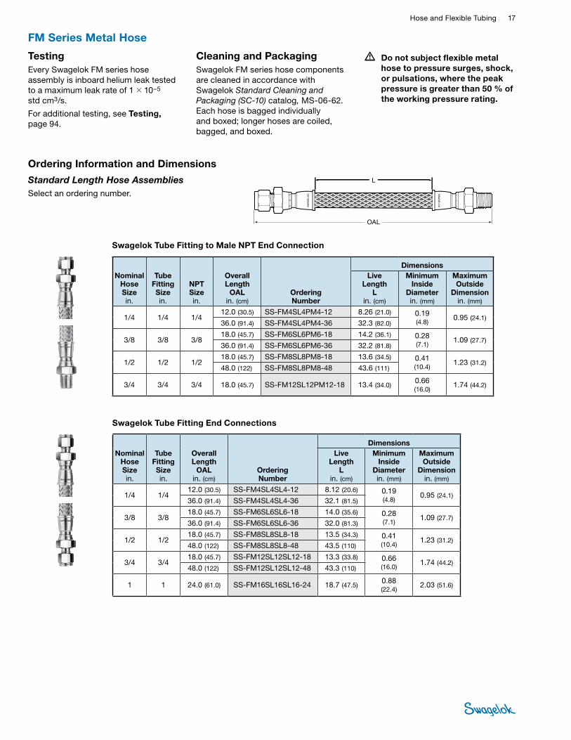
• Do not subject flexible metal hose to pressure surges, shock, or pulsations, where the peak pressure is greater than 50 % of the working pressure rating.
TestingEvery Swagelok FM series hose assembly is inboard helium leak tested to a maximum leak rate of 1 × 10⁻⁵ std cm3/s.
For additional testing, see Testing, page 94.
Cleaning and PackagingSwagelok FM series hose components are cleaned in accordance with Swagelok Standard Cleaning and Packaging (SC‑10) catalog, MS-06-62. Each hose is bagged individually and boxed; longer hoses are coiled, bagged, and boxed.
FM Series Metal Hose
Ordering Information and Dimensions
Standard Length Hose Assemblies Select an ordering number.
OAL
L
Swagelok Tube Fitting End Connections
Nominal Hose Size in.
Tube Fitting Size in.
Overall Length
OAL in. (cm)
Ordering Number
DimensionsLive
Length L
in. (cm)
Minimum Inside
Diameter in. (mm)
Maximum Outside
Dimension in. (mm)
1/4 1/4 12.0 (30.5) SS-FM4SL4SL4-12 8.12 (20.6) 0.19
(4.8) 0.95 (24.1)
36.0 (91.4) SS-FM4SL4SL4-36 32.1 (81.5)
3/8 3/8 18.0 (45.7) SS-FM6SL6SL6-18 14.0 (35.6) 0.28
(7.1) 1.09 (27.7)
36.0 (91.4) SS-FM6SL6SL6-36 32.0 (81.3)
1/2 1/2 18.0 (45.7) SS-FM8SL8SL8-18 13.5 (34.3) 0.41
(10.4) 1.23 (31.2)
48.0 (122) SS-FM8SL8SL8-48 43.5 (110)
3/4 3/4 18.0 (45.7) SS-FM12SL12SL12-18 13.3 (33.8) 0.66
(16.0) 1.74 (44.2)
48.0 (122) SS-FM12SL12SL12-48 43.3 (110)
1 1 24.0 (61.0) SS-FM16SL16SL16-24 18.7 (47.5) 0.88 (22.4)
2.03 (51.6)
Swagelok Tube Fitting to Male NPT End Connection
Nominal Hose Size in.
Tube Fitting Sizein.
NPT Sizein.
Overall Length
OAL in. (cm)
Ordering Number
DimensionsLive
Length L
in. (cm)
Minimum Inside
Diameter in. (mm)
Maximum Outside
Dimension in. (mm)
1/4 1/4 1/4 12.0 (30.5) SS-FM4SL4PM4-12 8.26 (21.0) 0.19
(4.8) 0.95 (24.1)
36.0 (91.4) SS-FM4SL4PM4-36 32.3 (82.0)
3/8 3/8 3/8 18.0 (45.7) SS-FM6SL6PM6-18 14.2 (36.1) 0.28
(7.1) 1.09 (27.7)
36.0 (91.4) SS-FM6SL6PM6-36 32.2 (81.8)
1/2 1/2 1/2 18.0 (45.7) SS-FM8SL8PM8-18 13.6 (34.5) 0.41
(10.4) 1.23 (31.2)
48.0 (122) SS-FM8SL8PM8-48 43.6 (111)
3/4 3/4 3/4 18.0 (45.7) SS-FM12SL12PM12-18 13.4 (34.0) 0.66 (16.0)
1.74 (44.2)
18 Hose, Quick-Connects, and Sample CylindersHO
SE /
FLEX
IBLE
TU
BING
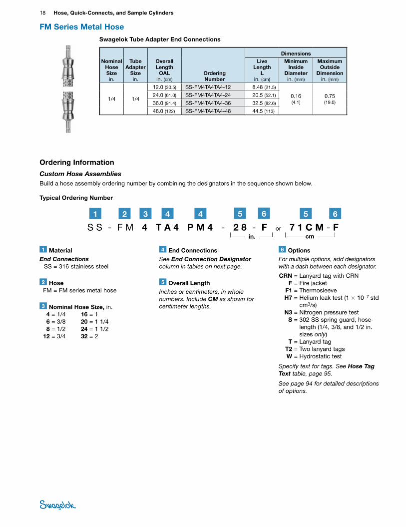
Typical Ordering Number
1 MaterialEnd Connections SS = 316 stainless steel
2 Hose FM = FM series metal hose
6 OptionsFor multiple options, add designators with a dash between each designator.
CRN = Lanyard tag with CRN F = Fire jacket F1 = Thermosleeve H7 = Helium leak test (1 × 10⁻⁷ std
cm3/s) N3 = Nitrogen pressure test S = 302 SS spring guard, hose-
length (1/4, 3/8, and 1/2 in. sizes only)
T = Lanyard tag T2 = Two lanyard tags W = Hydrostatic test
Specify text for tags. See Hose Tag Text table, page 95.
See page 94 for detailed descriptions of options.
3 Nominal Hose Size, in. 4 = 1/4 6 = 3/8 8 = 1/2 12 = 3/4
16 = 1 20 = 1 1/4 24 = 1 1/2 32 = 2
5 Overall LengthInches or centimeters, in whole numbers. Include CM as shown for centimeter lengths.
Ordering Information
Custom Hose Assemblies Build a hose assembly ordering number by combining the designators in the sequence shown below.
S S - F M 4 T A 4 P M 4 - 2 8 - F or 7 1 C M - F2 61 3 44 5
in. cm
65
4 End ConnectionsSee End Connection Designator column in tables on next page.
Swagelok Tube Adapter End Connections
Nominal Hose Size in.
Tube Adapter
Size in.
Overall Length
OAL in. (cm)
Ordering Number
DimensionsLive
Length L
in. (cm)
Minimum Inside
Diameter in. (mm)
Maximum Outside
Dimension in. (mm)
1/4 1/4
12.0 (30.5) SS-FM4TA4TA4-12 8.48 (21.5)
0.16 (4.1)
0.75 (19.0)
24.0 (61.0) SS-FM4TA4TA4-24 20.5 (52.1)
36.0 (91.4) SS-FM4TA4TA4-36 32.5 (82.6)
48.0 (122) SS-FM4TA4TA4-48 44.5 (113)
FM Series Metal Hose
A
Hose and Flexible Tubing 19 HOSE /
FLEXIBLE TUBING
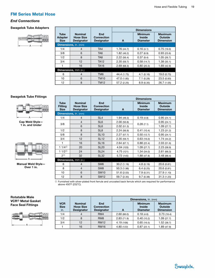
Swagelok Tube Adapters
A
Tube Adapter
Size
Nominal Hose Size Designator
End Connection Designator
Dimensions
A
Minimum Inside
Diameter
Maximum Outside
Dimension
Dimensions, in. (mm)
1/4 4 TA4 1.76 (44.7) 0.16 (4.1) 0.75 (19.0)
3/8 6 TA6 1.82 (46.2) 0.27 (6.9) 0.93 (23.6)
1/2 8 TA8 2.22 (56.4) 0.37 (9.4) 1.05 (26.7)
3/4 12 TA12 2.35 (59.7) 0.58 (14.7) 1.38 (35.1)
1 16 TA16 2.69 (68.3) 0.80 (20.3) 1.69 (42.9)
Dimensions, mm (in.) 6 4 TM6 44.4 (1.75) 4.1 (0.16) 19.0 (0.75)
10 6 TM10 47.0 (1.85) 7.1 (0.28) 23.5 (0.93)
12 8 TM12 57.2 (2.25) 8.9 (0.35) 26.7 (1.05)
End Connections
FM Series Metal Hose
Rotatable Male VCR® Metal Gasket Face Seal Fittings
A
VCR Size in.
Nominal Hose Size Designator
End Connection Designator
Dimensions, in. (mm)
A
Minimum Inside
Diameter
Maximum Outside
Dimension1/4 4 RM4 2.60 (66.0) 0.18 (4.6) 0.73 (18.4)
1/2 8 RM8 2.83 (71.9) 0.40 (10.2) 1.09 (27.7)
3/4 12 RM12 4.19 (106) 0.65 (16.5) 1.52 (38.7)
1 16 RM16 4.80 (122) 0.87 (22.1) 1.89 (47.9)
Swagelok Tube Fittings
A
Cap Weld Style— 1 in. and Under
Manual Weld Style— Over 1 in.
A
Tube Fitting Size
Nominal Hose Size Designator
End Connection Designator
Dimensions
A
Minimum Inside
Diameter
Maximum Outside
Dimension
Dimensions, in. (mm)
1/4 4 SL4 1.94 (49.3) 0.19 (4.8) 0.95 (24.1)
3/8 4 SL6 2.00 (50.8)
0.28 (7.1) 0.95 (24.1)
6 SL6 2.02 (51.3) 1.09 (27.7)
1/2 8 SL8 2.24 (56.9) 0.41 (10.4) 1.23 (31.2)
5/8 8 SL10 2.27 (57.7) 0.50 (12.7) 0.95 (24.1)
3/4 12 SL12 2.35 (59.7) 0.63 (16.0) 1.74 (44.2)
1 16 SL16 2.64 (67.1) 0.88 (22.4) 2.03 (51.6)
1 1/4➀ 20 SL20 4.04 (103) 1.09 (27.7) 2.23 (58.9)
1 1/2➀ 24 SL24 4.75 (121) 1.34 (34.0) 2.61 (66.3)
2➀ 32 SL32 5.72 (145) 1.88 (47.8) 3.48 (88.4)
Dimensions, mm (in.) 6 4 SM6 30.2 (1.19) 4.8 (0.19) 20.6 (0.81)
8 4 SM8 50.3 (1.98) 6.4 (0.25) 20.6 (0.81)
10 6 SM10 51.6 (2.03) 7.9 (0.31) 27.9 (1.10)
12 8 SM12 59.7 (2.35) 9.7 (0.38) 31.3 (1.23)
➀ Furnished with silver-plated front ferrule and uncoated back ferrule which are required for performance above 450˚F (232˚C).
20 Hose, Quick-Connects, and Sample CylindersHO
SE /
FLEX
IBLE
TU
BING
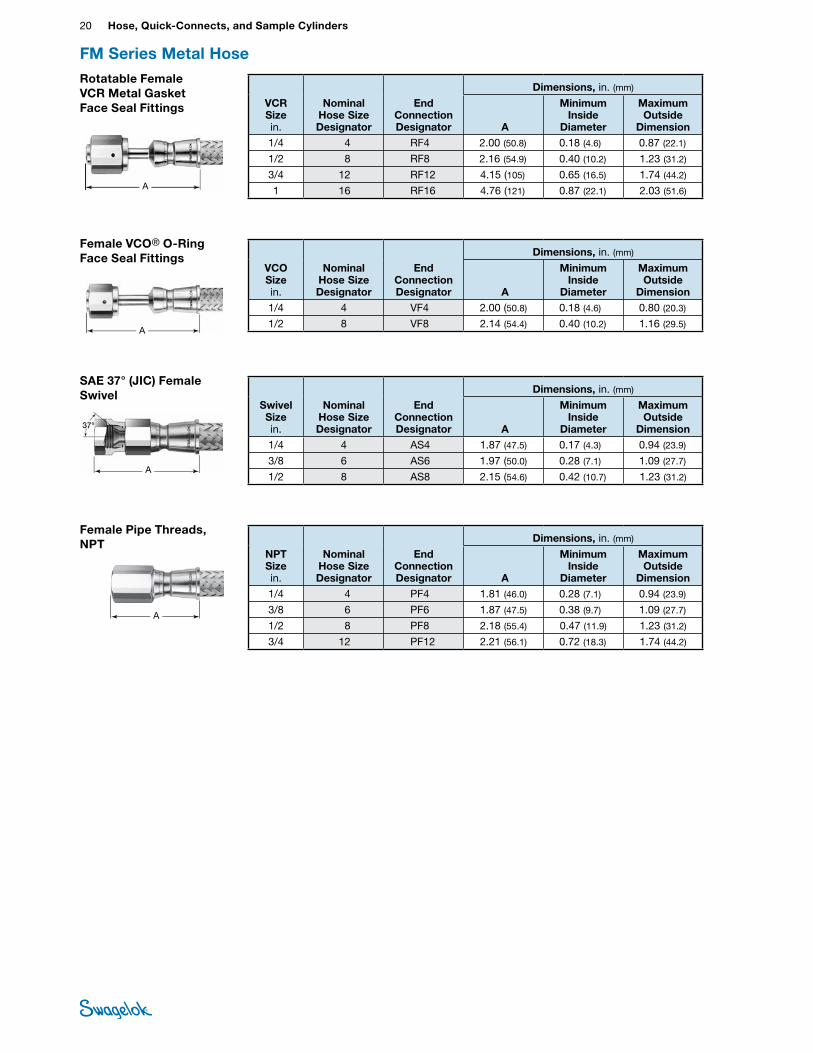
Female VCO® O-Ring Face Seal Fittings
A
VCO Size in.
Nominal Hose Size Designator
End Connection Designator
Dimensions, in. (mm)
A
Minimum Inside
Diameter
Maximum Outside
Dimension1/4 4 VF4 2.00 (50.8) 0.18 (4.6) 0.80 (20.3)
1/2 8 VF8 2.14 (54.4) 0.40 (10.2) 1.16 (29.5)
FM Series Metal Hose
Female Pipe Threads, NPT
A
NPT Size in.
Nominal Hose Size Designator
End Connection Designator
Dimensions, in. (mm)
A
Minimum Inside
Diameter
Maximum Outside
Dimension 1/4 4 PF4 1.81 (46.0) 0.28 (7.1) 0.94 (23.9)
3/8 6 PF6 1.87 (47.5) 0.38 (9.7) 1.09 (27.7)
1/2 8 PF8 2.18 (55.4) 0.47 (11.9) 1.23 (31.2)
3/4 12 PF12 2.21 (56.1) 0.72 (18.3) 1.74 (44.2)
SAE 37° (JIC) Female Swivel
A
Swivel Size in.
Nominal Hose Size Designator
End Connection Designator
Dimensions, in. (mm)
A
Minimum Inside
Diameter
Maximum Outside
Dimension 1/4 4 AS4 1.87 (47.5) 0.17 (4.3) 0.94 (23.9)
3/8 6 AS6 1.97 (50.0) 0.28 (7.1) 1.09 (27.7)
1/2 8 AS8 2.15 (54.6) 0.42 (10.7) 1.23 (31.2)
Rotatable Female VCR Metal Gasket Face Seal Fittings
A
VCR Size in.
Nominal Hose Size Designator
End Connection Designator
Dimensions, in. (mm)
A
Minimum Inside
Diameter
Maximum Outside
Dimension 1/4 4 RF4 2.00 (50.8) 0.18 (4.6) 0.87 (22.1)
1/2 8 RF8 2.16 (54.9) 0.40 (10.2) 1.23 (31.2)
3/4 12 RF12 4.15 (105) 0.65 (16.5) 1.74 (44.2)
1 16 RF16 4.76 (121) 0.87 (22.1) 2.03 (51.6)
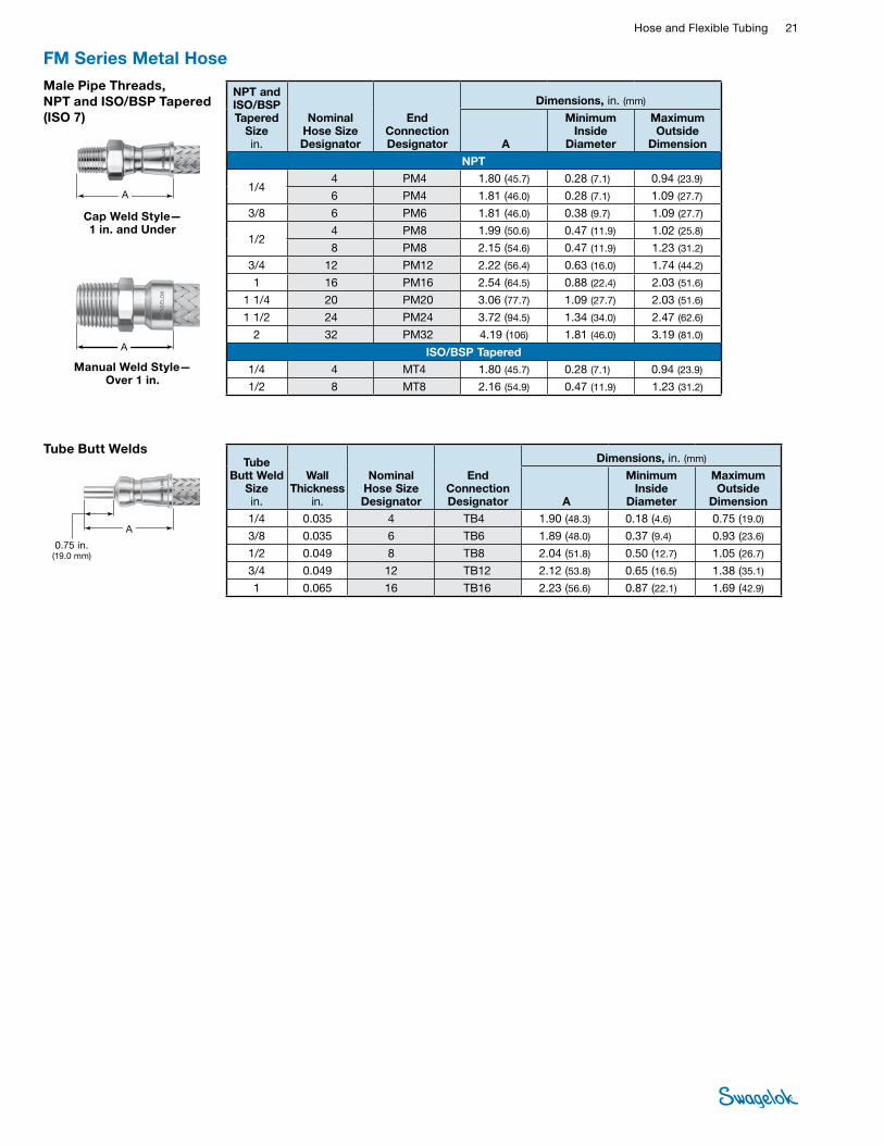
Hose and Flexible Tubing 21 HOSE /
FLEXIBLE TUBING
FM Series Metal HoseMale Pipe Threads, NPT and ISO/BSP Tapered (ISO 7)
A
Cap Weld Style— 1 in. and Under
Manual Weld Style— Over 1 in.
NPT and ISO/BSP Tapered
Size in.
Nominal Hose Size Designator
End Connection Designator
Dimensions, in. (mm)
A
Minimum Inside
Diameter
Maximum Outside
Dimension
NPT
1/4 4 PM4 1.80 (45.7) 0.28 (7.1) 0.94 (23.9)
6 PM4 1.81 (46.0) 0.28 (7.1) 1.09 (27.7)
3/8 6 PM6 1.81 (46.0) 0.38 (9.7) 1.09 (27.7)
1/2 4 PM8 1.99 (50.6) 0.47 (11.9) 1.02 (25.8)
8 PM8 2.15 (54.6) 0.47 (11.9) 1.23 (31.2)
3/4 12 PM12 2.22 (56.4) 0.63 (16.0) 1.74 (44.2)
1 16 PM16 2.54 (64.5) 0.88 (22.4) 2.03 (51.6)
1 1/4 20 PM20 3.06 (77.7) 1.09 (27.7) 2.03 (51.6)
1 1/2 24 PM24 3.72 (94.5) 1.34 (34.0) 2.47 (62.6)
2 32 PM32 4.19 (106) 1.81 (46.0) 3.19 (81.0)
ISO/BSP Tapered1/4 4 MT4 1.80 (45.7) 0.28 (7.1) 0.94 (23.9)
1/2 8 MT8 2.16 (54.9) 0.47 (11.9) 1.23 (31.2)
A
Tube Butt Welds
A
0.75 in. (19.0 mm)
Tube Butt Weld
Size in.
Wall Thickness
in.
Nominal Hose Size Designator
End Connection Designator
Dimensions, in. (mm)
A
Minimum Inside
Diameter
Maximum Outside
Dimension1/4 0.035 4 TB4 1.90 (48.3) 0.18 (4.6) 0.75 (19.0)
3/8 0.035 6 TB6 1.89 (48.0) 0.37 (9.4) 0.93 (23.6)
1/2 0.049 8 TB8 2.04 (51.8) 0.50 (12.7) 1.05 (26.7)
3/4 0.049 12 TB12 2.12 (53.8) 0.65 (16.5) 1.38 (35.1)
1 0.065 16 TB16 2.23 (56.6) 0.87 (22.1) 1.69 (42.9)
22 Hose, Quick-Connects, and Sample CylindersHO
SE /
FLEX
IBLE
TU
BING
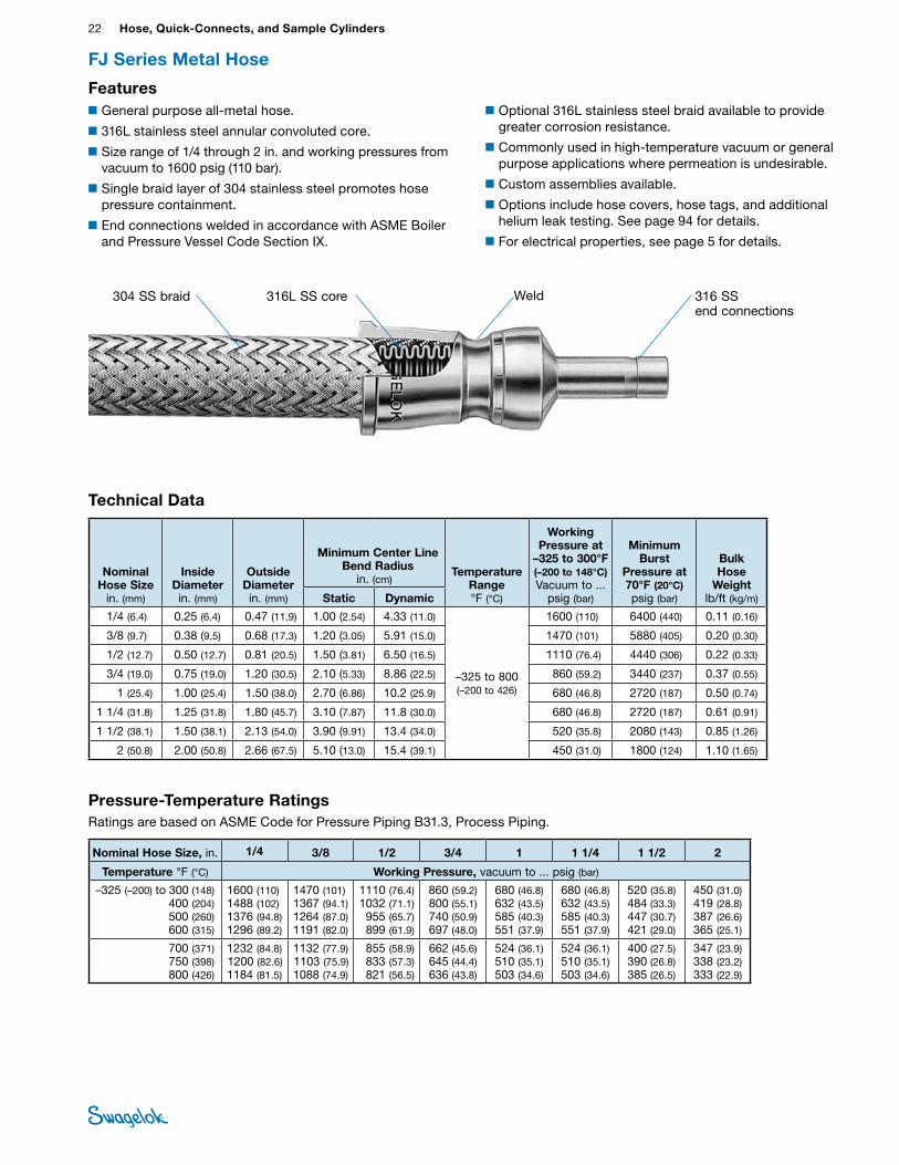
FJ Series Metal Hose
Technical Data
■General purpose all-metal hose.
■316L stainless steel annular convoluted core.
■Size range of 1/4 through 2 in. and working pressures from vacuum to 1600 psig (110 bar).
■Single braid layer of 304 stainless steel promotes hose pressure containment.
■End connections welded in accordance with ASME Boiler and Pressure Vessel Code Section IX.
■Optional 316L stainless steel braid available to provide greater corrosion resistance.
■Commonly used in high-temperature vacuum or general purpose applications where permeation is undesirable.
■Custom assemblies available.
■Options include hose covers, hose tags, and additional helium leak testing. See page 94 for details.
■For electrical properties, see page 5 for details.
Features
Nominal Hose Size
in. (mm)
Inside Diameter in. (mm)
Outside Diameter in. (mm)
Minimum Center Line Bend Radius
in. (cm) Temperature
Range °F (°C)
Working Pressure at
–325 to 300°F (–200 to 148°C) Vacuum to ...
psig (bar)
Minimum Burst
Pressure at 70°F (20°C) psig (bar)
Bulk Hose
Weightlb/ft (kg/m)Static Dynamic
1/4 (6.4) 0.25 (6.4) 0.47 (11.9) 1.00 (2.54) 4.33 (11.0)
–325 to 800 (–200 to 426)
1600 (110) 6400 (440) 0.11 (0.16)
3/8 (9.7) 0.38 (9.5) 0.68 (17.3) 1.20 (3.05) 5.91 (15.0) 1470 (101) 5880 (405) 0.20 (0.30)
1/2 (12.7) 0.50 (12.7) 0.81 (20.5) 1.50 (3.81) 6.50 (16.5) 1110 (76.4) 4440 (306) 0.22 (0.33)
3/4 (19.0) 0.75 (19.0) 1.20 (30.5) 2.10 (5.33) 8.86 (22.5) 860 (59.2) 3440 (237) 0.37 (0.55)
1 (25.4) 1.00 (25.4) 1.50 (38.0) 2.70 (6.86) 10.2 (25.9) 680 (46.8) 2720 (187) 0.50 (0.74)
1 1/4 (31.8) 1.25 (31.8) 1.80 (45.7) 3.10 (7.87) 11.8 (30.0) 680 (46.8) 2720 (187) 0.61 (0.91)
1 1/2 (38.1) 1.50 (38.1) 2.13 (54.0) 3.90 (9.91) 13.4 (34.0) 520 (35.8) 2080 (143) 0.85 (1.26)
2 (50.8) 2.00 (50.8) 2.66 (67.5) 5.10 (13.0) 15.4 (39.1) 450 (31.0) 1800 (124) 1.10 (1.65)
316L SS core304 SS braid 316 SS end connections
Weld
Nominal Hose Size, in. 1/4 3/8 1/2 3/4 1 1 1/4 1 1/2 2
Temperature °F (°C) Working Pressure, vacuum to ... psig (bar)
–325 (–200) to 300 (148) 400 (204) 500 (260) 600 (315)
1600 (110) 1488 (102)1376 (94.8)1296 (89.2)
1470 (101)1367 (94.1)1264 (87.0)1191 (82.0)
1110 (76.4) 1032 (71.1)955 (65.7)899 (61.9)
860 (59.2) 800 (55.1)740 (50.9)697 (48.0)
680 (46.8)632 (43.5)585 (40.3)551 (37.9)
680 (46.8)632 (43.5)585 (40.3)551 (37.9)
520 (35.8) 484 (33.3)447 (30.7)421 (29.0)
450 (31.0) 419 (28.8)387 (26.6)365 (25.1)
700 (371) 750 (398) 800 (426)
1232 (84.8) 1200 (82.6)1184 (81.5)
1132 (77.9) 1103 (75.9)1088 (74.9)
855 (58.9) 833 (57.3)821 (56.5)
662 (45.6) 645 (44.4)636 (43.8)
524 (36.1) 510 (35.1)503 (34.6)
524 (36.1)510 (35.1)503 (34.6)
400 (27.5)390 (26.8)385 (26.5)
347 (23.9)338 (23.2)333 (22.9)
Pressure-Temperature RatingsRatings are based on ASME Code for Pressure Piping B31.3, Process Piping.
Hose and Flexible Tubing 23 HOSE /
FLEXIBLE TUBING
TestingEvery Swagelok FJ series hose assembly is inboard helium leak tested to a maximum leak rate of 1 × 10⁻⁵ std cm3/s.
For additional testing, see Testing, page 94.
• Do not subject flexible metal hose to pressure surges, shock, or pulsations, where the peak pressure is greater than 50 % of the working pressure rating.
Cleaning and PackagingSwagelok FJ series hose components are cleaned in accordance with Swagelok Standard Cleaning and Packaging (SC‑10) catalog, MS-06-62. Each hose is bagged individually and boxed; longer hoses are coiled, bagged, and boxed.
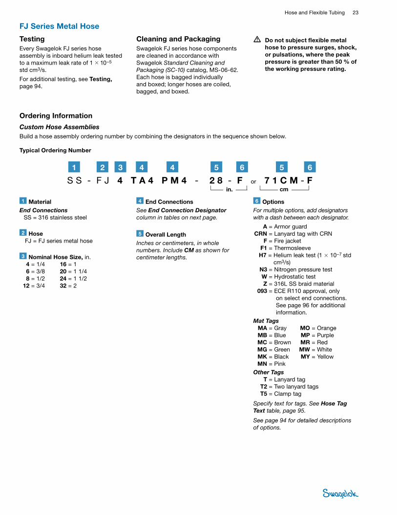
1 MaterialEnd Connections SS = 316 stainless steel
2 Hose FJ = FJ series metal hose
6 OptionsFor multiple options, add designators with a dash between each designator.
A = Armor guard CRN = Lanyard tag with CRN F = Fire jacket F1 = Thermosleeve H7 = Helium leak test (1 × 10⁻⁷ std
cm3/s) N3 = Nitrogen pressure test W = Hydrostatic test Z = 316L SS braid material 093 = ECE R110 approval, only
on select end connections. See page 96 for additional information.
Mat Tags MA = Gray MO = Orange MB = Blue MP = Purple MC = Brown MR = Red MG = Green MW = White MK = Black MY = Yellow MN = PinkOther Tags T = Lanyard tag T2 = Two lanyard tags T5 = Clamp tag
Specify text for tags. See Hose Tag Text table, page 95.
See page 94 for detailed descriptions of options.
3 Nominal Hose Size, in. 4 = 1/4 6 = 3/8 8 = 1/2 12 = 3/4
16 = 1 20 = 1 1/4 24 = 1 1/2 32 = 2
4 End ConnectionsSee End Connection Designator column in tables on next page.
Typical Ordering Number
5 Overall LengthInches or centimeters, in whole numbers. Include CM as shown for centimeter lengths.
Ordering Information
Custom Hose Assemblies Build a hose assembly ordering number by combining the designators in the sequence shown below.
S S - F J 4 T A 4 P M 4 - 2 8 - F or 7 1 C M - F2 61 3 44 5 65
in. cm
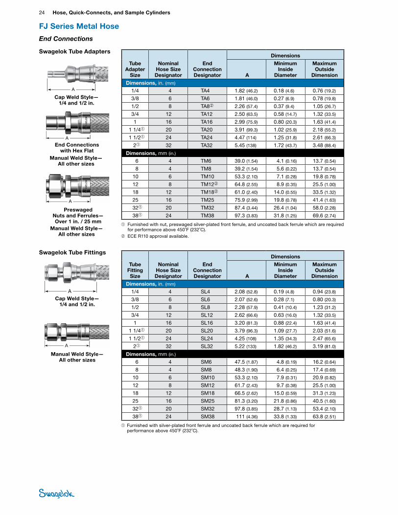
FJ Series Metal Hose
24 Hose, Quick-Connects, and Sample CylindersHO
SE /
FLEX
IBLE
TU
BING
A
A
Swagelok Tube Adapters
Tube Adapter
Size
Nominal Hose Size Designator
End Connection Designator
Dimensions
A
Minimum Inside
Diameter
Maximum Outside
Dimension
Dimensions, in. (mm)
1/4 4 TA4 1.82 (46.2) 0.18 (4.6) 0.76 (19.2)
3/8 6 TA6 1.81 (46.0) 0.27 (6.9) 0.78 (19.8)
1/2 8 TA8➁ 2.26 (57.4) 0.37 (9.4) 1.05 (26.7)
3/4 12 TA12 2.50 (63.5) 0.58 (14.7) 1.32 (33.5)
1 16 TA16 2.99 (75.9) 0.80 (20.3) 1.63 (41.4)
1 1/4➀ 20 TA20 3.91 (99.3) 1.02 (25.9) 2.18 (55.2)
1 1/2➀ 24 TA24 4.47 (114) 1.25 (31.8) 2.61 (66.3)
2➀ 32 TA32 5.45 (138) 1.72 (43.7) 3.48 (88.4)
Dimensions, mm (in.) 6 4 TM6 39.0 (1.54) 4.1 (0.16) 13.7 (0.54)
8 4 TM8 39.2 (1.54) 5.6 (0.22) 13.7 (0.54)
10 6 TM10 53.3 (2.10) 7.1 (0.28) 19.8 (0.78)
12 8 TM12➁ 64.8 (2.55) 8.9 (0.35) 25.5 (1.00)
18 12 TM18➁ 61.0 (2.40) 14.0 (0.55) 33.5 (1.32)
25 16 TM25 75.9 (2.99) 19.8 (0.78) 41.4 (1.63)
32➀ 20 TM32 87.4 (3.44) 26.4 (1.04) 58.0 (2.28)
38➀ 24 TM38 97.3 (3.83) 31.8 (1.25) 69.6 (2.74)
➀ Furnished with nut, preswaged silver-plated front ferrule, and uncoated back ferrule which are required for performance above 450˚F (232˚C).
➁ ECE R110 approval available.
End Connections with Hex Flat
Preswaged Nuts and Ferrules— Over 1 in. / 25 mm
End Connections
FJ Series Metal Hose
Swagelok Tube Fittings
A
Tube Fitting Size
Nominal Hose Size Designator
End Connection Designator
Dimensions
A
Minimum Inside
Diameter
Maximum Outside
Dimension
Dimensions, in. (mm)
1/4 4 SL4 2.08 (52.8) 0.19 (4.8) 0.94 (23.8)
3/8 6 SL6 2.07 (52.6) 0.28 (7.1) 0.80 (20.3)
1/2 8 SL8 2.28 (57.9) 0.41 (10.4) 1.23 (31.2)
3/4 12 SL12 2.62 (66.6) 0.63 (16.0) 1.32 (33.5)
1 16 SL16 3.20 (81.3) 0.88 (22.4) 1.63 (41.4)
1 1/4➀ 20 SL20 3.79 (96.3) 1.09 (27.7) 2.03 (51.6)
1 1/2➀ 24 SL24 4.25 (108) 1.35 (34.3) 2.47 (65.6)
2➀ 32 SL32 5.22 (133) 1.82 (46.2) 3.19 (81.0)
Dimensions, mm (in.) 6 4 SM6 47.5 (1.87) 4.8 (0.19) 16.2 (0.64)
8 4 SM8 48.3 (1.90) 6.4 (0.25) 17.4 (0.69)
10 6 SM10 53.3 (2.10) 7.9 (0.31) 20.9 (0.82)
12 8 SM12 61.7 (2.43) 9.7 (0.38) 25.5 (1.00)
18 12 SM18 66.5 (2.62) 15.0 (0.59) 31.3 (1.23)
25 16 SM25 81.3 (3.20) 21.8 (0.86) 40.5 (1.60)
32➀ 20 SM32 97.8 (3.85) 28.7 (1.13) 53.4 (2.10)
38➀ 24 SM38 111 (4.36) 33.8 (1.33) 63.8 (2.51)
➀ Furnished with silver-plated front ferrule and uncoated back ferrule which are required for performance above 450˚F (232˚C).
ACap Weld Style—
1/4 and 1/2 in.
Manual Weld Style— All other sizes
A
Cap Weld Style— 1/4 and 1/2 in.
Manual Weld Style— All other sizes
Manual Weld Style— All other sizes
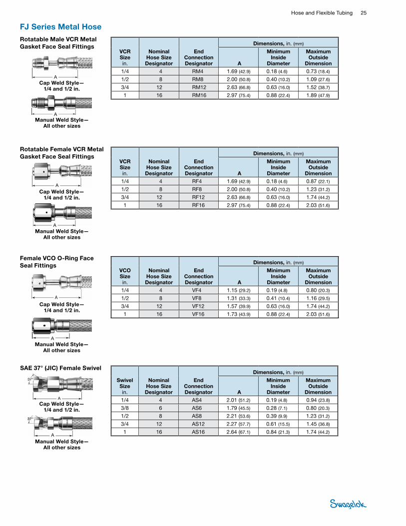
Hose and Flexible Tubing 25 HOSE /
FLEXIBLE TUBING
FJ Series Metal HoseRotatable Male VCR Metal Gasket Face Seal Fittings
A
VCR Size in.
Nominal Hose Size Designator
End Connection Designator
Dimensions, in. (mm)
A
Minimum Inside
Diameter
Maximum Outside
Dimension 1/4 4 RM4 1.69 (42.9) 0.18 (4.6) 0.73 (18.4)
1/2 8 RM8 2.00 (50.8) 0.40 (10.2) 1.09 (27.6)
3/4 12 RM12 2.63 (66.8) 0.63 (16.0) 1.52 (38.7)
1 16 RM16 2.97 (75.4) 0.88 (22.4) 1.89 (47.9)
Female VCO O-Ring Face Seal Fittings
A
VCO Size in.
Nominal Hose Size Designator
End Connection Designator
Dimensions, in. (mm)
A
Minimum Inside
Diameter
Maximum Outside
Dimension 1/4 4 VF4 1.15 (29.2) 0.19 (4.8) 0.80 (20.3)
1/2 8 VF8 1.31 (33.3) 0.41 (10.4) 1.16 (29.5)
3/4 12 VF12 1.57 (39.9) 0.63 (16.0) 1.74 (44.2)
1 16 VF16 1.73 (43.9) 0.88 (22.4) 2.03 (51.6)
Rotatable Female VCR Metal Gasket Face Seal Fittings
A
VCR Size in.
Nominal Hose Size Designator
End Connection Designator
Dimensions, in. (mm)
A
Minimum Inside
Diameter
Maximum Outside
Dimension1/4 4 RF4 1.69 (42.9) 0.18 (4.6) 0.87 (22.1)
1/2 8 RF8 2.00 (50.8) 0.40 (10.2) 1.23 (31.2)
3/4 12 RF12 2.63 (66.8) 0.63 (16.0) 1.74 (44.2)
1 16 RF16 2.97 (75.4) 0.88 (22.4) 2.03 (51.6)
SAE 37° (JIC) Female Swivel
A
Swivel Size in.
Nominal Hose Size Designator
End Connection Designator
Dimensions, in. (mm)
A
Minimum Inside
Diameter
Maximum Outside
Dimension 1/4 4 AS4 2.01 (51.2) 0.19 (4.8) 0.94 (23.8)
3/8 6 AS6 1.79 (45.5) 0.28 (7.1) 0.80 (20.3)
1/2 8 AS8 2.21 (53.6) 0.39 (9.9) 1.23 (31.2)
3/4 12 AS12 2.27 (57.7) 0.61 (15.5) 1.45 (36.8)
1 16 AS16 2.64 (67.1) 0.84 (21.3) 1.74 (44.2)
A
A
A
Cap Weld Style— 1/4 and 1/2 in.
Manual Weld Style— All other sizes
Manual Weld Style— All other sizes
Cap Weld Style— 1/4 and 1/2 in.
Manual Weld Style— All other sizes
Cap Weld Style— 1/4 and 1/2 in.
Manual Weld Style— All other sizes
ACap Weld Style—
1/4 and 1/2 in.
26 Hose, Quick-Connects, and Sample CylindersHO
SE /
FLEX
IBLE
TU
BING
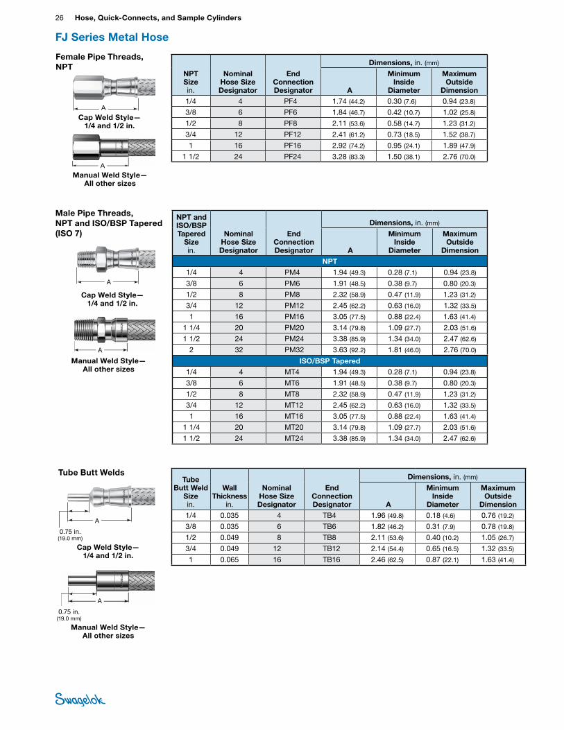
FJ Series Metal Hose
Tube Butt Weld
Size in.
Wall Thickness
in.
Nominal Hose Size Designator
End Connection Designator
Dimensions, in. (mm)
A
Minimum Inside
Diameter
Maximum Outside
Dimension1/4 0.035 4 TB4 1.96 (49.8) 0.18 (4.6) 0.76 (19.2)
3/8 0.035 6 TB6 1.82 (46.2) 0.31 (7.9) 0.78 (19.8)
1/2 0.049 8 TB8 2.11 (53.6) 0.40 (10.2) 1.05 (26.7)
3/4 0.049 12 TB12 2.14 (54.4) 0.65 (16.5) 1.32 (33.5)
1 0.065 16 TB16 2.46 (62.5) 0.87 (22.1) 1.63 (41.4)
Tube Butt Welds
A
0.75 in. (19.0 mm)
Male Pipe Threads, NPT and ISO/BSP Tapered (ISO 7)
NPT and ISO/BSP Tapered
Size in.
Nominal Hose Size Designator
End Connection Designator
Dimensions, in. (mm)
A
Minimum Inside
Diameter
Maximum Outside
Dimension
NPT1/4 4 PM4 1.94 (49.3) 0.28 (7.1) 0.94 (23.8)
3/8 6 PM6 1.91 (48.5) 0.38 (9.7) 0.80 (20.3)
1/2 8 PM8 2.32 (58.9) 0.47 (11.9) 1.23 (31.2)
3/4 12 PM12 2.45 (62.2) 0.63 (16.0) 1.32 (33.5)
1 16 PM16 3.05 (77.5) 0.88 (22.4) 1.63 (41.4)
1 1/4 20 PM20 3.14 (79.8) 1.09 (27.7) 2.03 (51.6)
1 1/2 24 PM24 3.38 (85.9) 1.34 (34.0) 2.47 (62.6)
2 32 PM32 3.63 (92.2) 1.81 (46.0) 2.76 (70.0)
ISO/BSP Tapered1/4 4 MT4 1.94 (49.3) 0.28 (7.1) 0.94 (23.8)
3/8 6 MT6 1.91 (48.5) 0.38 (9.7) 0.80 (20.3)
1/2 8 MT8 2.32 (58.9) 0.47 (11.9) 1.23 (31.2)
3/4 12 MT12 2.45 (62.2) 0.63 (16.0) 1.32 (33.5)
1 16 MT16 3.05 (77.5) 0.88 (22.4) 1.63 (41.4)
1 1/4 20 MT20 3.14 (79.8) 1.09 (27.7) 2.03 (51.6)
1 1/2 24 MT24 3.38 (85.9) 1.34 (34.0) 2.47 (62.6)
A
Female Pipe Threads, NPT
NPT Size in.
Nominal Hose Size Designator
End Connection Designator
Dimensions, in. (mm)
A
Minimum Inside
Diameter
Maximum Outside
Dimension 1/4 4 PF4 1.74 (44.2) 0.30 (7.6) 0.94 (23.8)
3/8 6 PF6 1.84 (46.7) 0.42 (10.7) 1.02 (25.8)
1/2 8 PF8 2.11 (53.6) 0.58 (14.7) 1.23 (31.2)
3/4 12 PF12 2.41 (61.2) 0.73 (18.5) 1.52 (38.7)
1 16 PF16 2.92 (74.2) 0.95 (24.1) 1.89 (47.9)
1 1/2 24 PF24 3.28 (83.3) 1.50 (38.1) 2.76 (70.0)
A
A
Manual Weld Style— All other sizes
Cap Weld Style— 1/4 and 1/2 in.
Cap Weld Style— 1/4 and 1/2 in.
Manual Weld Style— All other sizes
A
0.75 in. (19.0 mm)
Cap Weld Style— 1/4 and 1/2 in.
Manual Weld Style— All other sizes
A
A
Hose and Flexible Tubing 27 HOSE /
FLEXIBLE TUBING
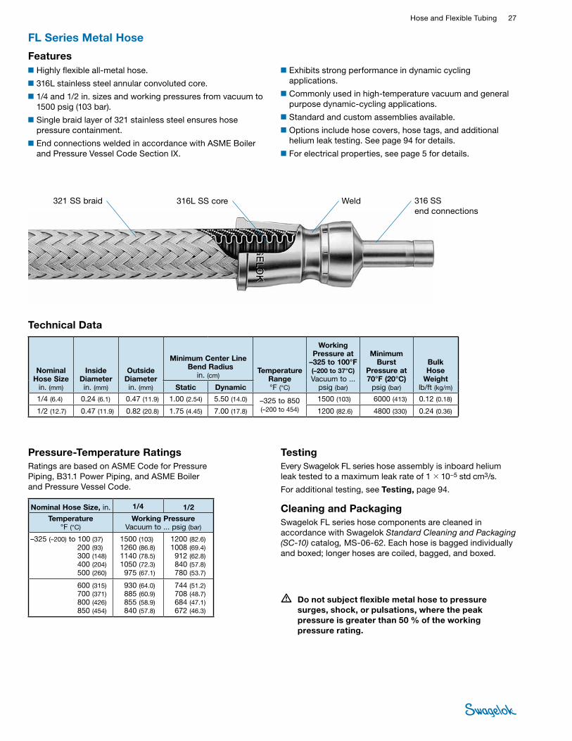
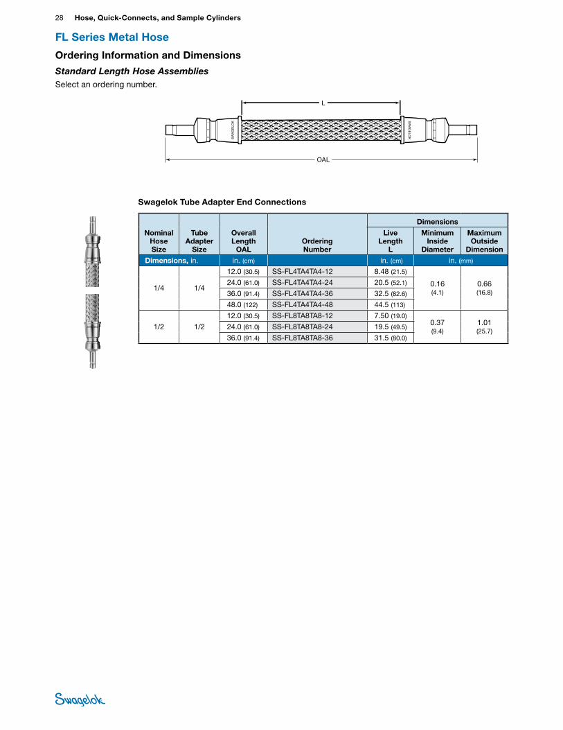
FL Series Metal Hose
Technical Data
Nominal Hose Size
in. (mm)
Inside Diameter in. (mm)
Outside Diameter in. (mm)
Minimum Center Line Bend Radius
in. (cm) Temperature
Range °F (°C)
Working Pressure at
–325 to 100°F (–200 to 37°C) Vacuum to ...
psig (bar)
Minimum Burst
Pressure at 70°F (20°C)
psig (bar)
Bulk Hose
Weightlb/ft (kg/m)Static Dynamic
1/4 (6.4) 0.24 (6.1) 0.47 (11.9) 1.00 (2.54) 5.50 (14.0) –325 to 850 (–200 to 454)
1500 (103) 6000 (413) 0.12 (0.18)
1/2 (12.7) 0.47 (11.9) 0.82 (20.8) 1.75 (4.45) 7.00 (17.8) 1200 (82.6) 4800 (330) 0.24 (0.36)
321 SS braid 316L SS core 316 SS end connections
Features■Highly flexible all-metal hose.
■316L stainless steel annular convoluted core.
■1/4 and 1/2 in. sizes and working pressures from vacuum to 1500 psig (103 bar).
■Single braid layer of 321 stainless steel ensures hose pressure containment.
■End connections welded in accordance with ASME Boiler and Pressure Vessel Code Section IX.
■Exhibits strong performance in dynamic cycling applications.
■Commonly used in high-temperature vacuum and general purpose dynamic-cycling applications.
■Standard and custom assemblies available.
■Options include hose covers, hose tags, and additional helium leak testing. See page 94 for details.
■For electrical properties, see page 5 for details.
Weld
Nominal Hose Size, in. 1/4 1/2
Temperature °F (°C)
Working Pressure Vacuum to ... psig (bar)
–325 (–200) to 100 (37)200 (93) 300 (148) 400 (204) 500 (260)
1500 (103) 1260 (86.8)1140 (78.5)1050 (72.3)975 (67.1)
1200 (82.6) 1008 (69.4)912 (62.8)840 (57.8)780 (53.7)
600 (315) 700 (371) 800 (426) 850 (454)
930 (64.0)885 (60.9)855 (58.9)840 (57.8)
744 (51.2)708 (48.7)684 (47.1)672 (46.3)
Pressure-Temperature RatingsRatings are based on ASME Code for Pressure Piping, B31.1 Power Piping, and ASME Boiler and Pressure Vessel Code.
TestingEvery Swagelok FL series hose assembly is inboard helium leak tested to a maximum leak rate of 1 × 10⁻⁵ std cm3/s.
For additional testing, see Testing, page 94.
Cleaning and PackagingSwagelok FL series hose components are cleaned in accordance with Swagelok Standard Cleaning and Packaging (SC‑10) catalog, MS-06-62. Each hose is bagged individually and boxed; longer hoses are coiled, bagged, and boxed.
• Do not subject flexible metal hose to pressure surges, shock, or pulsations, where the peak pressure is greater than 50 % of the working pressure rating.
Tube Butt Weld
Size in.
Wall Thickness
in.
Nominal Hose Size Designator
End Connection Designator
Dimensions, in. (mm)
A
Minimum Inside
Diameter
Maximum Outside
Dimension1/4 0.035 4 TB4 1.96 (49.8) 0.18 (4.6) 0.76 (19.2)
3/8 0.035 6 TB6 1.82 (46.2) 0.31 (7.9) 0.78 (19.8)
1/2 0.049 8 TB8 2.11 (53.6) 0.40 (10.2) 1.05 (26.7)
3/4 0.049 12 TB12 2.14 (54.4) 0.65 (16.5) 1.32 (33.5)
1 0.065 16 TB16 2.46 (62.5) 0.87 (22.1) 1.63 (41.4)
28 Hose, Quick-Connects, and Sample CylindersHO
SE /
FLEX
IBLE
TU
BING Swagelok Tube Adapter End Connections
OAL
L
Nominal Hose Size
Tube Adapter
Size
Overall Length
OALOrdering Number
Dimensions
Live Length
L
Minimum Inside
Diameter
Maximum Outside
Dimension
Dimensions, in. in. (cm) in. (cm) in. (mm)
1/4 1/4
12.0 (30.5) SS-FL4TA4TA4-12 8.48 (21.5)
0.16 (4.1)
0.66 (16.8)
24.0 (61.0) SS-FL4TA4TA4-24 20.5 (52.1)
36.0 (91.4) SS-FL4TA4TA4-36 32.5 (82.6)
48.0 (122) SS-FL4TA4TA4-48 44.5 (113)
1/2 1/2
12.0 (30.5) SS-FL8TA8TA8-12 7.50 (19.0) 0.37 (9.4)
1.01 (25.7)
24.0 (61.0) SS-FL8TA8TA8-24 19.5 (49.5)
36.0 (91.4) SS-FL8TA8TA8-36 31.5 (80.0)
FL Series Metal Hose
Ordering Information and Dimensions
Standard Length Hose Assemblies Select an ordering number.
Hose and Flexible Tubing 29 HOSE /
FLEXIBLE TUBING
See next page for more end connections.
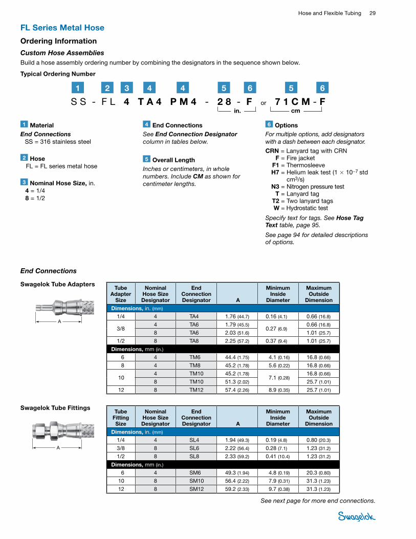
Swagelok Tube Fittings
A
Tube Fitting Size
Nominal Hose Size Designator
End Connection Designator A
Minimum Inside
Diameter
Maximum Outside
Dimension
Dimensions, in. (mm)
1/4 4 SL4 1.94 (49.3) 0.19 (4.8) 0.80 (20.3)
3/8 8 SL6 2.22 (56.4) 0.28 (7.1) 1.23 (31.2)
1/2 8 SL8 2.33 (59.2) 0.41 (10.4) 1.23 (31.2)
Dimensions, mm (in.) 6 4 SM6 49.3 (1.94) 4.8 (0.19) 20.3 (0.80)
10 8 SM10 56.4 (2.22) 7.9 (0.31) 31.3 (1.23)
12 8 SM12 59.2 (2.33) 9.7 (0.38) 31.3 (1.23)
Swagelok Tube Adapters
A
Tube Adapter
Size
Nominal Hose Size Designator
End Connection Designator A
Minimum Inside
Diameter
Maximum Outside
Dimension
Dimensions, in. (mm)
1/4 4 TA4 1.76 (44.7) 0.16 (4.1) 0.66 (16.8)
3/8 4 TA6 1.79 (45.5)
0.27 (6.9) 0.66 (16.8)
8 TA6 2.03 (51.6) 1.01 (25.7)
1/2 8 TA8 2.25 (57.2) 0.37 (9.4) 1.01 (25.7)
Dimensions, mm (in.) 6 4 TM6 44.4 (1.75) 4.1 (0.16) 16.8 (0.66)
8 4 TM8 45.2 (1.78) 5.6 (0.22) 16.8 (0.66)
10 4 TM10 45.2 (1.78)
7.1 (0.28) 16.8 (0.66)
8 TM10 51.3 (2.02) 25.7 (1.01)
12 8 TM12 57.4 (2.26) 8.9 (0.35) 25.7 (1.01)
FL Series Metal Hose
1 MaterialEnd Connections SS = 316 stainless steel
2 Hose FL = FL series metal hose
6 OptionsFor multiple options, add designators with a dash between each designator.
CRN = Lanyard tag with CRN F = Fire jacket F1 = Thermosleeve H7 = Helium leak test (1 × 10⁻⁷ std
cm3/s) N3 = Nitrogen pressure test T = Lanyard tag T2 = Two lanyard tags W = Hydrostatic test
Specify text for tags. See Hose Tag Text table, page 95.
See page 94 for detailed descriptions of options.
3 Nominal Hose Size, in. 4 = 1/4 8 = 1/2
4 End ConnectionsSee End Connection Designator column in tables below.
S S - F L 4 T A 4 P M 4 - 2 8 - F or 7 1 C M - F2 61 3 44 5
5 Overall LengthInches or centimeters, in whole numbers. Include CM as shown for centimeter lengths.
End Connections
Typical Ordering Number
Ordering Information
Custom Hose Assemblies Build a hose assembly ordering number by combining the designators in the sequence shown below.
65
in. cm
30 Hose, Quick-Connects, and Sample CylindersHO
SE /
FLEX
IBLE
TU
BING
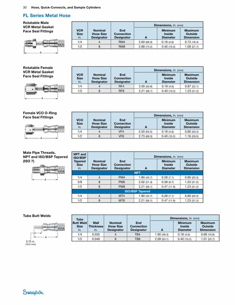
Rotatable Female VCR Metal Gasket Face Seal Fittings
A
VCR Size in.
Nominal Hose Size Designator
End Connection Designator
Dimensions, in. (mm)
A
Minimum Inside
Diameter
Maximum Outside
Dimension1/4 4 RF4 2.00 (50.8) 0.18 (4.6) 0.87 (22.1)
1/2 8 RF8 2.21 (56.1) 0.40 (10.2) 1.23 (31.2)
Rotatable Male VCR Metal Gasket Face Seal Fittings
A
VCR Size in.
Nominal Hose Size Designator
End Connection Designator
Dimensions, in. (mm)
A
Minimum Inside
Diameter
Maximum Outside
Dimension1/4 4 RM4 2.60 (66.0) 0.18 (4.6) 0.73 (18.4)
1/2 8 RM8 2.88 (73.2) 0.40 (10.2) 1.09 (27.7)
Female VCO O-Ring Face Seal Fittings
A
VCO Size in.
Nominal Hose Size Designator
End Connection Designator
Dimensions, in. (mm)
A
Minimum Inside
Diameter
Maximum Outside
Dimension1/4 4 VF4 2.50 (63.5) 0.18 (4.6) 0.80 (20.3)
1/2 8 VF8 2.73 (69.3) 0.40 (10.2) 1.16 (29.5)
Tube Butt Welds
A
0.75 in. (19.0 mm)
Tube Butt Weld
Size in.
Wall Thickness
in.
Nominal Hose Size Designator
End Connection Designator
Dimensions, in. (mm)
A
Minimum Inside
Diameter
Maximum Outside
Dimension1/4 0.035 4 TB4 1.90 (48.3) 0.18 (4.6) 0.66 (16.8)
1/2 0.049 8 TB8 2.09 (53.1) 0.40 (10.2) 1.01 (25.7)
FL Series Metal Hose
Male Pipe Threads, NPT and ISO/BSP Tapered (ISO 7)
A
NPT and ISO/BSP Tapered
Size in.
Nominal Hose Size Designator
End Connection Designator
Dimensions, in. (mm)
A
Minimum Inside
Diameter
Maximum Outside
Dimension
NPT1/4 4 PM4 1.80 (45.7) 0.28 (7.1) 0.80 (20.3)
3/8 8 PM6 2.02 (51.3) 0.38 (9.7) 1.23 (31.2)
1/2 8 PM8 2.21 (56.1) 0.47 (11.9) 1.23 (31.2)
ISO/BSP Tapered1/4 4 MT4 1.80 (45.7) 0.28 (7.1) 0.80 (20.3)
1/2 8 MT8 2.21 (56.1) 0.47 (11.9) 1.23 (31.2)
Hose and Flexible Tubing 31 HOSE /
FLEXIBLE TUBING
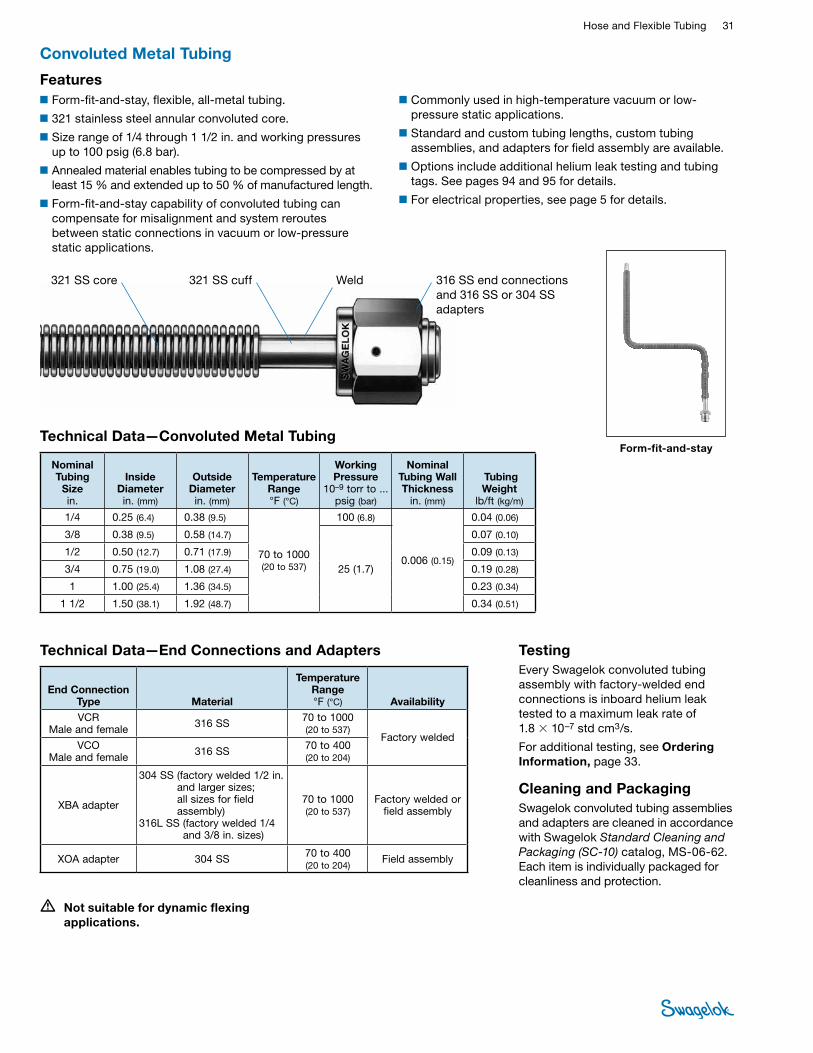
Convoluted Metal Tubing
■Form-fit-and-stay, flexible, all-metal tubing.
■321 stainless steel annular convoluted core.
■Size range of 1/4 through 1 1/2 in. and working pressures up to 100 psig (6.8 bar).
■Annealed material enables tubing to be compressed by at least 15 % and extended up to 50 % of manufactured length.
■Form-fit-and-stay capability of convoluted tubing can compensate for misalignment and system reroutes between static connections in vacuum or low-pressure static applications.
Features■Commonly used in high-temperature vacuum or low-
pressure static applications.
■Standard and custom tubing lengths, custom tubing assemblies, and adapters for field assembly are available.
■Options include additional helium leak testing and tubing tags. See pages 94 and 95 for details.
■For electrical properties, see page 5 for details.
• Not suitable for dynamic flexing applications.
Technical Data—Convoluted Metal Tubing
Nominal Tubing
Sizein.
Inside Diameter in. (mm)
Outside Diameter in. (mm)
Temperature Range °F (°C)
Working Pressure
10–9 torr to ... psig (bar)
Nominal Tubing Wall Thickness
in. (mm)
TubingWeight
lb/ft (kg/m)
1/4 0.25 (6.4) 0.38 (9.5)
70 to 1000 (20 to 537)
100 (6.8)
0.006 (0.15)
0.04 (0.06)
3/8 0.38 (9.5) 0.58 (14.7)
25 (1.7)
0.07 (0.10)
1/2 0.50 (12.7) 0.71 (17.9) 0.09 (0.13)
3/4 0.75 (19.0) 1.08 (27.4) 0.19 (0.28)
1 1.00 (25.4) 1.36 (34.5) 0.23 (0.34)
1 1/2 1.50 (38.1) 1.92 (48.7) 0.34 (0.51)
321 SS core 321 SS cuff 316 SS end connections and 316 SS or 304 SS adapters
Weld
Form-fit-and-stay
End Connection Type Material
Temperature Range °F (°C) Availability
VCR Male and female 316 SS 70 to 1000
(20 to 537) Factory welded
VCO Male and female 316 SS 70 to 400
(20 to 204)
XBA adapter
304 SS (factory welded 1/2 in. and larger sizes; all sizes for field assembly)
316L SS (factory welded 1/4 and 3/8 in. sizes)
70 to 1000 (20 to 537)
Factory welded or field assembly
XOA adapter 304 SS 70 to 400 (20 to 204)
Field assembly
Technical Data—End Connections and Adapters TestingEvery Swagelok convoluted tubing assembly with factory-welded end connections is inboard helium leak tested to a maximum leak rate of 1.8 × 10⁻⁷ std cm3/s.
For additional testing, see Ordering Information, page 33.
Cleaning and PackagingSwagelok convoluted tubing assemblies and adapters are cleaned in accordance with Swagelok Standard Cleaning and Packaging (SC‑10) catalog, MS-06-62. Each item is individually packaged for cleanliness and protection.
32 Hose, Quick-Connects, and Sample CylindersHO
SE /
FLEX
IBLE
TU
BING
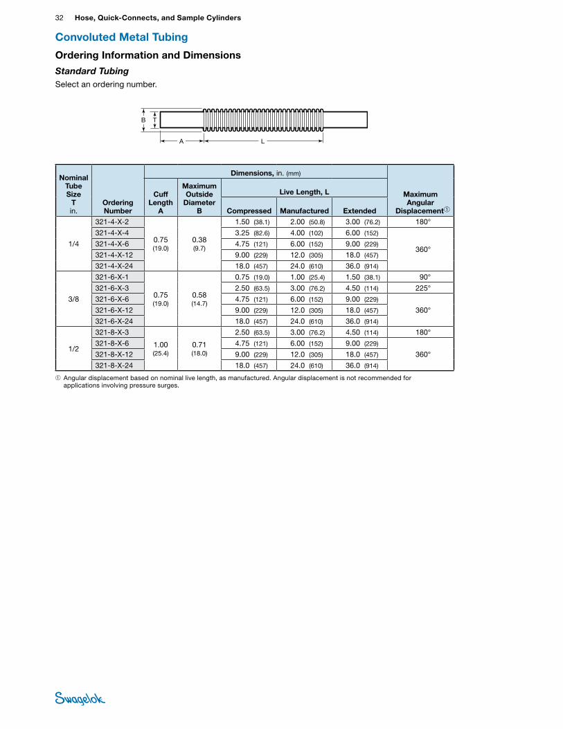
Ordering Information and Dimensions
Standard TubingSelect an ordering number.
Convoluted Metal Tubing
T
LA
B
➀ Angular displacement based on nominal live length, as manufactured. Angular displacement is not recommended for applications involving pressure surges.
NominalTube Size
T in.
Ordering Number
Dimensions, in. (mm)
Maximum Angular
Displacement➀
Cuff Length
A
Maximum Outside
Diameter B
Live Length, L
Compressed Manufactured Extended
1/4
321-4-X-2
0.75 (19.0)
0.38 (9.7)
1.50 (38.1) 2.00 (50.8) 3.00 (76.2) 180°
321-4-X-4 3.25 (82.6) 4.00 (102) 6.00 (152)
360° 321-4-X-6 4.75 (121) 6.00 (152) 9.00 (229)
321-4-X-12 9.00 (229) 12.0 (305) 18.0 (457)
321-4-X-24 18.0 (457) 24.0 (610) 36.0 (914)
3/8
321-6-X-1
0.75 (19.0)
0.58 (14.7)
0.75 (19.0) 1.00 (25.4) 1.50 (38.1) 90°
321-6-X-3 2.50 (63.5) 3.00 (76.2) 4.50 (114) 225°
321-6-X-6 4.75 (121) 6.00 (152) 9.00 (229)
360°321-6-X-12 9.00 (229) 12.0 (305) 18.0 (457)
321-6-X-24 18.0 (457) 24.0 (610) 36.0 (914)
1/2
321-8-X-3
1.00(25.4)
0.71(18.0)
2.50 (63.5) 3.00 (76.2) 4.50 (114) 180°
321-8-X-6 4.75 (121) 6.00 (152) 9.00 (229)
360° 321-8-X-12 9.00 (229) 12.0 (305) 18.0 (457)
321-8-X-24 18.0 (457) 24.0 (610) 36.0 (914)
Hose and Flexible Tubing 33 HOSE /
FLEXIBLE TUBING
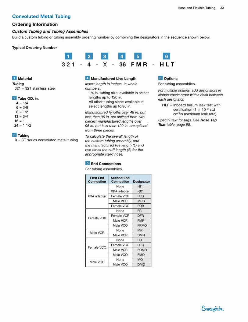
Typical Ordering Number
Convoluted Metal Tubing
1 MaterialTubing 321 = 321 stainless steel
2 Tube OD, in. 4 = 1/4 6 = 3/8 8 = 1/2 12 = 3/4 16 = 1 24 = 1 1/2
5 End Connections For tubing assemblies.
First End Connection
Second End Connection Designator
XBA adapter
None -B1
XBA adapter -B2
Female VCR FRB
Male VCR MRB
Female VCO FOB
Female VCR
None FR
Female VCR DFR
Male VCR FMR
Male VCO FRMO
Male VCRNone MR
Male VCR DMR
Female VCO
None FO
Female VCO DFO
Male VCR FOMR
Male VCO FMO
Male VCONone MO
Male VCO DMO
3 Tubing X = CT series convoluted metal tubing
4 Manufactured Live Length Insert length in inches, in whole numbers. 1/4 in. tubing size: available in select
lengths up to 120 in. All other tubing sizes: available in
select lengths up to 96 in.
Manufactured lengths over 48 in. but less than 96 in. are spliced from two pieces; manufactured lengths over 96 in. but less than 120 in. are spliced from three pieces.
To calculate the overall length of the custom tubing assembly, add the manufactured live length (L) and two times the cuff length (A) for the appropriate sized hose.
3 2 1 - 4 - X - 36 F M R - H L T21 3 54
6 OptionsFor tubing assemblies.
For multiple options, add designators in alphanumeric order with a dash between each designator.
HLT = Inboard helium leak test with certification (1 × 10⁻⁹ std cm3/s maximum leak rate)
Specify text for tags. See Hose Tag Text table, page 95.
6
Ordering Information
Custom Tubing and Tubing AssembliesBuild a custom tubing or tubing assembly ordering number by combining the designators in the sequence shown below.
34 Hose, Quick-Connects, and Sample CylindersHO
SE /
FLEX
IBLE
TU
BING
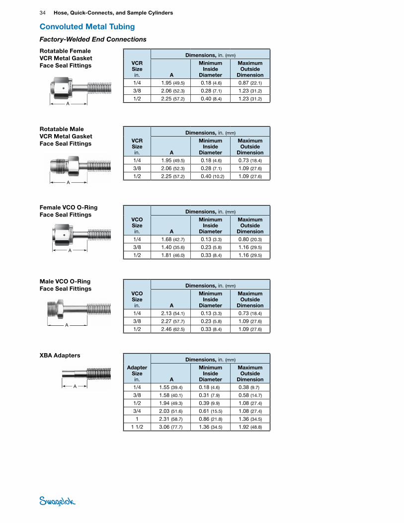
Convoluted Metal Tubing
Rotatable Female VCR Metal Gasket Face Seal Fittings VCR
Size in.
Dimensions, in. (mm)
A
Minimum Inside
Diameter
Maximum Outside
Dimension1/4 1.95 (49.5) 0.18 (4.6) 0.87 (22.1)
3/8 2.06 (52.3) 0.28 (7.1) 1.23 (31.2)
1/2 2.25 (57.2) 0.40 (8.4) 1.23 (31.2) A
AdapterSize in.
Dimensions, in. (mm)
A
Minimum Inside
Diameter
Maximum Outside
Dimension1/4 1.55 (39.4) 0.18 (4.6) 0.38 (9.7)
3/8 1.58 (40.1) 0.31 (7.9) 0.58 (14.7)
1/2 1.94 (49.3) 0.39 (9.9) 1.08 (27.4)
3/4 2.03 (51.6) 0.61 (15.5) 1.08 (27.4)
1 2.31 (58.7) 0.86 (21.8) 1.36 (34.5)
1 1/2 3.06 (77.7) 1.36 (34.5) 1.92 (48.8)
XBA Adapters
A
Rotatable Male VCR Metal Gasket Face Seal Fittings
A
VCR Size in.
Dimensions, in. (mm)
A
Minimum Inside
Diameter
Maximum Outside
Dimension1/4 1.95 (49.5) 0.18 (4.6) 0.73 (18.4)
3/8 2.06 (52.3) 0.28 (7.1) 1.09 (27.6)
1/2 2.25 (57.2) 0.40 (10.2) 1.09 (27.6)
Male VCO O-Ring Face Seal Fittings
A
VCO Size in.
Dimensions, in. (mm)
A
Minimum Inside
Diameter
Maximum Outside
Dimension1/4 2.13 (54.1) 0.13 (3.3) 0.73 (18.4)
3/8 2.27 (57.7) 0.23 (5.8) 1.09 (27.6)
1/2 2.46 (62.5) 0.33 (8.4) 1.09 (27.6)
Female VCO O-Ring Face Seal Fittings
A
VCO Size in.
Dimensions, in. (mm)
A
Minimum Inside
Diameter
Maximum Outside
Dimension1/4 1.68 (42.7) 0.13 (3.3) 0.80 (20.3)
3/8 1.40 (35.6) 0.23 (5.8) 1.16 (29.5)
1/2 1.81 (46.0) 0.33 (8.4) 1.16 (29.5)
Factory-Welded End Connections
Hose and Flexible Tubing 35 HOSE /
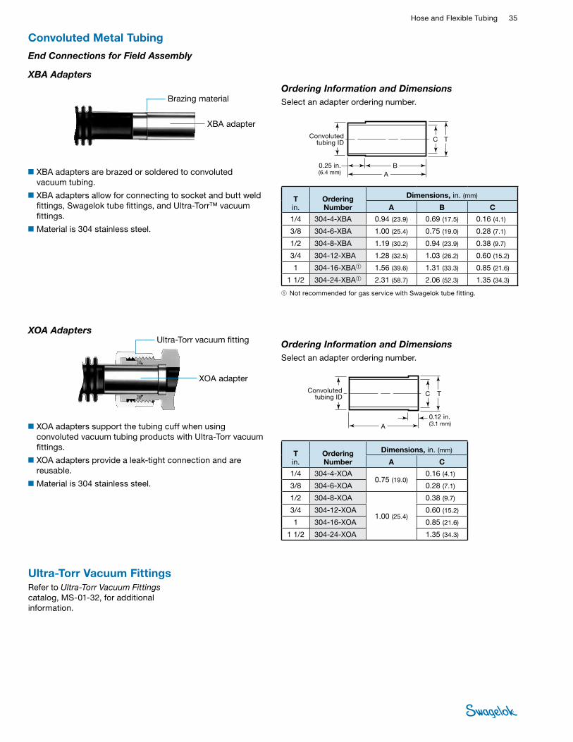
FLEXIBLE TUBING
XBA Adapters
■XBA adapters are brazed or soldered to convoluted vacuum tubing.
■XBA adapters allow for connecting to socket and butt weld fittings, Swagelok tube fittings, and Ultra-Torr™ vacuum fittings.
■Material is 304 stainless steel.
XBA adapter
Brazing material
Convoluted tubing ID
BA
C T
0.25 in. (6.4 mm)
Ordering Information and DimensionsSelect an adapter ordering number.
➀ Not recommended for gas service with Swagelok tube fitting.
T in.
Ordering Number
Dimensions, in. (mm)
A B C
1/4 304-4-XBA 0.94 (23.9) 0.69 (17.5) 0.16 (4.1)
3/8 304-6-XBA 1.00 (25.4) 0.75 (19.0) 0.28 (7.1)
1/2 304-8-XBA 1.19 (30.2) 0.94 (23.9) 0.38 (9.7)
3/4 304-12-XBA 1.28 (32.5) 1.03 (26.2) 0.60 (15.2)
1 304-16-XBA➀ 1.56 (39.6) 1.31 (33.3) 0.85 (21.6)
1 1/2 304-24-XBA➀ 2.31 (58.7) 2.06 (52.3) 1.35 (34.3)
TC
0.12 in. (3.1 mm)
XOA Adapters
XOA adapter
Ultra-Torr vacuum fitting
Convoluted tubing ID
A
Ordering Information and DimensionsSelect an adapter ordering number.
T in.
Ordering Number
Dimensions, in. (mm)
A C
1/4 304-4-XOA 0.75 (19.0)
0.16 (4.1)
3/8 304-6-XOA 0.28 (7.1)
1/2 304-8-XOA
1.00 (25.4)
0.38 (9.7)
3/4 304-12-XOA 0.60 (15.2)
1 304-16-XOA 0.85 (21.6)
1 1/2 304-24-XOA 1.35 (34.3)
■XOA adapters support the tubing cuff when using convoluted vacuum tubing products with Ultra-Torr vacuum fittings.
■XOA adapters provide a leak-tight connection and are reusable.
■Material is 304 stainless steel.
Convoluted Metal Tubing
End Connections for Field Assembly
Ultra-Torr Vacuum FittingsRefer to Ultra‑Torr Vacuum Fittings catalog, MS-01-32, for additional information.
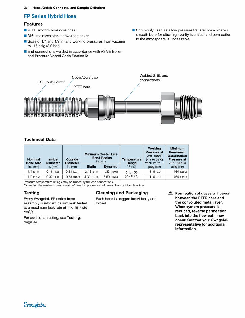
36 Hose, Quick-Connects, and Sample CylindersHO
SE /
FLEX
IBLE
TU
BING
FP Series Hybrid Hose
Technical Data
Nominal Hose Size
in. (mm)
Inside Diameter in. (mm)
Outside Diameter in. (mm)
Minimum Center Line Bend Radius
in. (cm) Temperature
Range °F (°C)
Working Pressure at 0 to 150°F (–17 to 65°C)
Vacuum to ... psig (bar)
Minimum Permanent
Deformation Pressure at 70°F (20°C)
psig (bar) Static Dynamic
1/4 (6.4) 0.18 (4.6) 0.38 (9.7) 2.13 (5.4) 4.33 (10.9) 0 to 150 (–17 to 65)
116 (8.0) 464 (32.0)
1/2 (12.7) 0.37 (9.4) 0.73 (18.5) 4.33 (10.9) 6.50 (16.5) 116 (8.0) 464 (32.0)
SWAGELO
KSW
AGELO
K
316L outer coverPTFE core
Welded 316L end connections
Features■PTFE smooth bore core hose.
■316L stainless steel convoluted cover.
■Sizes of 1/4 and 1/2 in. and working pressures from vacuum to 116 psig (8.0 bar).
■End connections welded in accordance with ASME Boiler and Pressure Vessel Code Section IX.
■Commonly used as a low pressure transfer hose where a smooth bore for ultra-high purity is critical and permeation to the atmosphere is undesirable.
Cover/Core gap
Pressure-temperature ratings may be limited by the end connections. Exceeding the minimum permanent deformation pressure could result in core tube distortion.
Testing Every Swagelok FP series hose assembly is inboard helium leak tested to a maximum leak rate of 1 × 10⁻⁹ std cm3/s.
For additional testing, see Testing, page 94
Cleaning and PackagingEach hose is bagged individually and boxed.
• Permeation of gases will occur between the PTFE core and the convoluted metal layer. When system pressure is reduced, reverse permeation back into the flow path may occur. Contact your Swagelok representative for additional information.
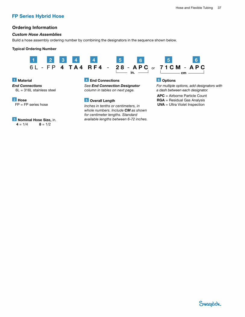
Hose and Flexible Tubing 37 HOSE /
FLEXIBLE TUBING
FP Series Hybrid Hose
1 MaterialEnd Connections 6L = 316L stainless steel
2 Hose FP = FP series hose
6 OptionsFor multiple options, add designators with a dash between each designator.
APC = Airborne Particle Count RGA = Residual Gas Analysis UVA = Ultra Violet Inspection
3 Nominal Hose Size, in. 4 = 1/4 8 = 1/2
4 End ConnectionsSee End Connection Designator column in tables on next page.
Typical Ordering Number
5 Overall LengthInches in tenths or centimeters, in whole numbers. Include CM as shown for centimeter lengths. Standard available lengths between 6‑72 inches.
Ordering Information
Custom Hose Assemblies Build a hose assembly ordering number by combining the designators in the sequence shown below.
6 L - F P 4 T A 4 R F 4 - 2 8 - A P C or 7 1 C M - A P C21 3 44 5 5
in. cm
6 6
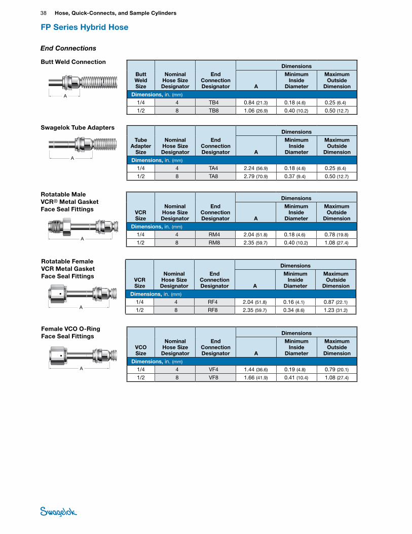
38 Hose, Quick-Connects, and Sample CylindersHO
SE /
FLEX
IBLE
TU
BING
Swagelok Tube Adapters
Tube Adapter
Size
Nominal Hose Size Designator
End Connection Designator
Dimensions
A
Minimum Inside
Diameter
Maximum Outside
Dimension
Dimensions, in. (mm)
1/4 4 TA4 2.24 (56.9) 0.18 (4.6) 0.25 (6.4)
1/2 8 TA8 2.79 (70.9) 0.37 (9.4) 0.50 (12.7)
End Connections
FP Series Hybrid Hose
VCR Size
Nominal Hose Size Designator
End Connection Designator
Dimensions
A
Minimum Inside
Diameter
Maximum Outside
Dimension
Dimensions, in. (mm)
1/4 4 RM4 2.04 (51.8) 0.18 (4.6) 0.78 (19.8)
1/2 8 RM8 2.35 (59.7) 0.40 (10.2) 1.08 (27.4)
VCO Size
Nominal Hose Size Designator
End Connection Designator
Dimensions
A
Minimum Inside
Diameter
Maximum Outside
Dimension
Dimensions, in. (mm)
1/4 4 VF4 1.44 (36.6) 0.19 (4.8) 0.79 (20.1)
1/2 8 VF8 1.66 (41.9) 0.41 (10.4) 1.08 (27.4)
VCR Size
Nominal Hose Size Designator
End Connection Designator
Dimensions
A
Minimum Inside
Diameter
Maximum Outside
Dimension
Dimensions, in. (mm)
1/4 4 RF4 2.04 (51.8) 0.16 (4.1) 0.87 (22.1)
1/2 8 RF8 2.35 (59.7) 0.34 (8.6) 1.23 (31.2)
Rotatable Male VCR® Metal Gasket Face Seal Fittings
Female VCO O-Ring Face Seal Fittings
SWAGELO
KSW
AGELO
K
A
A
Rotatable Female VCR Metal Gasket Face Seal Fittings
Butt Weld Connection
Butt Weld Size
Nominal Hose Size Designator
End Connection Designator
Dimensions
A
Minimum Inside
Diameter
Maximum Outside
Dimension
Dimensions, in. (mm)
1/4 4 TB4 0.84 (21.3) 0.18 (4.6) 0.25 (6.4)
1/2 8 TB8 1.06 (26.9) 0.40 (10.2) 0.50 (12.7)
SWAGELO
KSW
AGELO
K
A
A
SWAGELOK
SWAGELOK
A
AA
SWAGELOK
SWAGELOK
A
AA
SWAGELOK
SWAGELOK
A
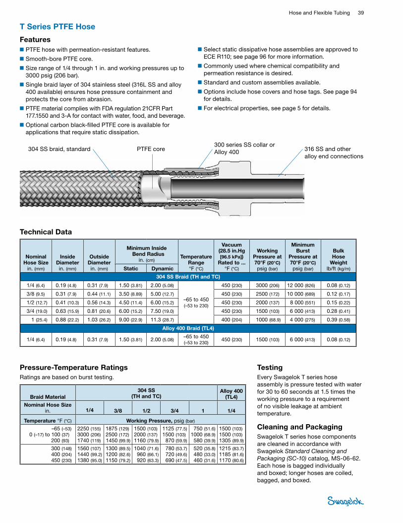
Hose and Flexible Tubing 39 HOSE /
FLEXIBLE TUBING
■Select static dissipative hose assemblies are approved to ECE R110; see page 96 for more information.
■Commonly used where chemical compatibility and permeation resistance is desired.
■Standard and custom assemblies available.
■Options include hose covers and hose tags. See page 94 for details.
■For electrical properties, see page 5 for details.
T Series PTFE Hose
Technical Data
Nominal Hose Size
in. (mm)
Inside Diameter in. (mm)
Outside Diameter in. (mm)
Minimum Inside Bend Radius
in. (cm) Temperature
Range °F (°C)
Vacuum (28.5 in.Hg [96.5 kPa])
Rated to ...°F (°C)
Working Pressure at 70°F (20°C) psig (bar)
Minimum Burst
Pressure at 70°F (20°C) psig (bar)
Bulk Hose
Weightlb/ft (kg/m)Static Dynamic
304 SS Braid (TH and TC)
1/4 (6.4) 0.19 (4.8) 0.31 (7.9) 1.50 (3.81) 2.00 (5.08)
–65 to 450 (–53 to 230)
450 (230) 3000 (206) 12 000 (826) 0.08 (0.12)
3/8 (9.5) 0.31 (7.9) 0.44 (11.1) 3.50 (8.89) 5.00 (12.7) 450 (230) 2500 (172) 10 000 (689) 0.12 (0.17)
1/2 (12.7) 0.41 (10.3) 0.56 (14.3) 4.50 (11.4) 6.00 (15.2) 450 (230) 2000 (137) 8 000 (551) 0.15 (0.22)
3/4 (19.0) 0.63 (15.9) 0.81 (20.6) 6.00 (15.2) 7.50 (19.0) 450 (230) 1500 (103) 6 000 (413) 0.28 (0.41)
1 (25.4) 0.88 (22.2) 1.03 (26.2) 9.00 (22.9) 11.3 (28.7) 400 (204) 1000 (68.9) 4 000 (275) 0.39 (0.58)
Alloy 400 Braid (TL4)
1/4 (6.4) 0.19 (4.8) 0.31 (7.9) 1.50 (3.81) 2.00 (5.08) –65 to 450 (–53 to 230)
450 (230) 1500 (103) 6 000 (413) 0.08 (0.12)
■PTFE hose with permeation-resistant features.
■Smooth-bore PTFE core.
■Size range of 1/4 through 1 in. and working pressures up to 3000 psig (206 bar).
■Single braid layer of 304 stainless steel (316L SS and alloy 400 available) ensures hose pressure containment and protects the core from abrasion.
■PTFE material complies with FDA regulation 21CFR Part 177.1550 and 3-A for contact with water, food, and beverage.
■Optional carbon black-filled PTFE core is available for applications that require static dissipation.
Features
304 SS braid, standard PTFE core 300 series SS collar or Alloy 400 316 SS and other
alloy end connections
TestingEvery Swagelok T series hose assembly is pressure tested with water for 30 to 60 seconds at 1.5 times the working pressure to a requirement of no visible leakage at ambient temperature.
Cleaning and PackagingSwagelok T series hose components are cleaned in accordance with Swagelok Standard Cleaning and Packaging (SC‑10) catalog, MS-06-62. Each hose is bagged individually and boxed; longer hoses are coiled, bagged, and boxed.
Braid Material304 SS
(TH and TC)Alloy 400
(TL4)
Nominal Hose Size in. 1/4 3/8 1/2 3/4 1 1/4
Temperature °F (°C) Working Pressure, psig (bar) –65 (–53)
0 (–17) to 100 (37)200 (93)
2250 (155) 3000 (206) 1740 (119)
1875 (129)2500 (172)1450 (99.9)
1500 (103) 2000 (137)1160 (79.9)
1125 (77.5) 1500 (103)
870 (59.9)
750 (51.6)1000 (68.9)580 (39.9)
1500 (103) 1500 (103)1305 (89.9)
300 (148) 400 (204) 450 (230)
1560 (107)1440 (99.2)1380 (95.0)
1300 (89.5)1200 (82.6)1150 (79.2)
1040 (71.6)960 (66.1)920 (63.3)
780 (53.7)720 (49.6)690 (47.5)
520 (35.8)480 (33.0)460 (31.6)
1215 (83.7)1185 (81.6)1170 (80.6)
Pressure-Temperature RatingsRatings are based on burst testing.
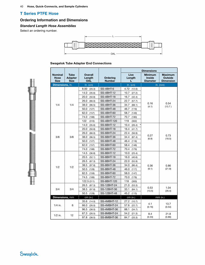
40 Hose, Quick-Connects, and Sample CylindersHO
SE /
FLEX
IBLE
TU
BING
OAL
Swagelok Tube Adapter End Connections
L
Ordering Information and Dimensions
Standard Length Hose Assemblies Select an ordering number.
T Series PTFE Hose
Nominal Hose Size
Tube Adapter
Size
Overall Length
OALOrdering Number
Dimensions
Live Length
L
Minimum Inside
Diameter
Maximum Outside
Dimension
Dimensions, in. in. (cm) in. (cm) in. (mm)
1/4 1/4
8.00 (20.3) SS-4BHT-6 4.72 (12.0)
0.16 (4.1)
0.54 (13.7 )
14.0 (35.6) SS-4BHT-12 10.7 (27.2)
20.0 (50.8) SS-4BHT-18 16.7 (42.4)
26.0 (66.0) SS-4BHT-24 22.7 (57.7)
38.0 (96.5) SS-4BHT-36 34.7 (88.1)
50.0 (127) SS-4BHT-48 46.7 (119)
62.0 (157) SS-4BHT-60 58.7 (149)
74.0 (188) SS-4BHT-72 70.7 (180)
122 (310) SS-4BHT-120 119 (302)
3/8 3/8
14.0 (35.6) SS-6BHT-12 10.4 (26.4)
0.27 (6.9)
0.73 (18.5)
20.0 (50.8) SS-6BHT-18 16.4 (41.7)
26.0 (66.0) SS-6BHT-24 22.4 (56.9)
38.0 (96.5) SS-6BHT-36 34.4 (87.4)
50.0 (127) SS-6BHT-48 46.4 (118)
62.0 (157) SS-6BHT-60 58.4 (148)
74.0 (188) SS-6BHT-72 70.4 (179)
1/2 1/2
14.5 (36.8) SS-8BHT-12 10.0 (25.4)
0.36 (9.1)
0.86 (21.8)
20.5 (52.1) SS-8BHT-18 16.0 (40.6)
26.5 (67.3) SS-8BHT-24 22.0 (55.9)
38.5 (97.8) SS-8BHT-36 34.0 (86.4)
50.5 (128) SS-8BHT-48 46.0 (117)
62.5 (159) SS-8BHT-60 58.0 (147)
74.5 (189) SS-8BHT-72 70.0 (178)
122.5 (311) SS-8BHT-120 118 (300)
3/4 3/4
26.5 (67.3) SS-12BHT-24 21.0 (53.3) 0.53 (13.5)
1.04 (26.4)
38.5 (97.8) SS-12BHT-36 33.1 (84.1)
50.5 (128) SS-12BHT-48 45.2 (115)
Dimensions, mm cm (in.) cm (in.) mm (in.)
1/4 in. 6
35.6 (14.0) SS-4MBHT-12 27.2 (10.7) 4.1
(0.16) 13.7 (0.54)
66.0 (26.0) SS-4MBHT-24 57.6 (22.7)
96.5 (38.0) SS-4MBHT-36 88.1 (34.7)
1/2 in. 12 67.3 (26.5) SS-8MBHT-24 54.2 (21.3) 8.4
(0.33) 21.8 (0.86) 97.8 (38.5) SS-8MBHT-36 84.7 (33.3)
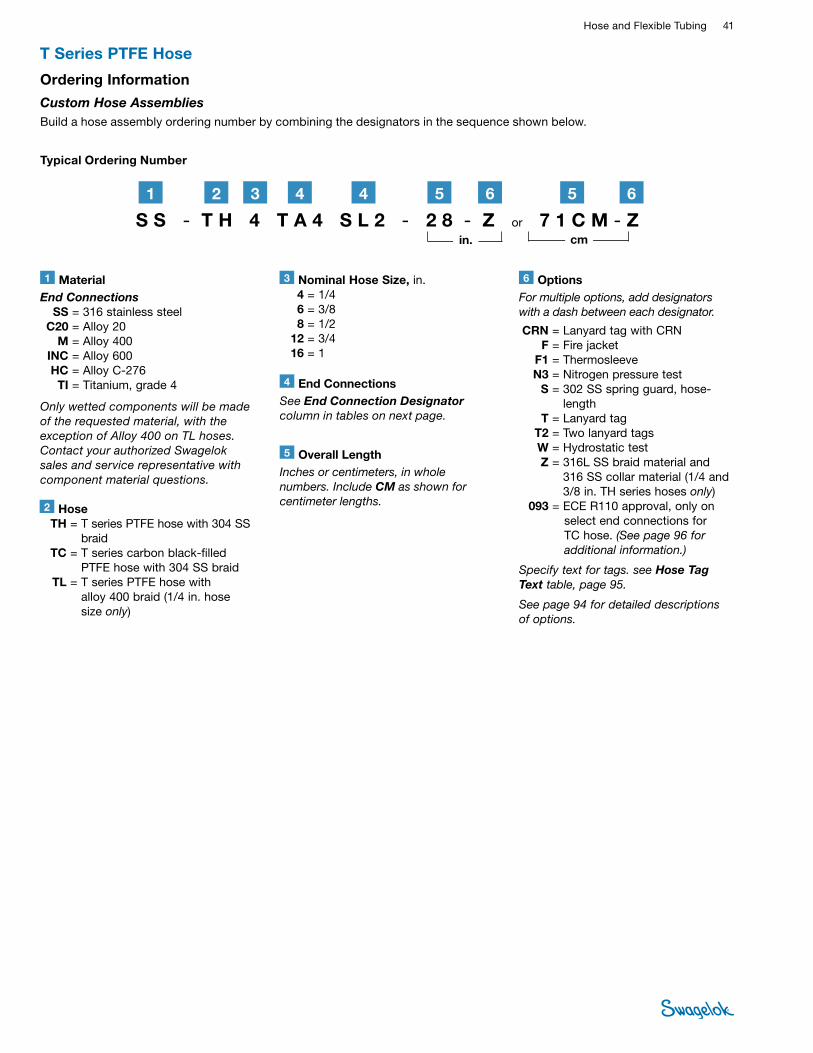
Hose and Flexible Tubing 41 HOSE /
FLEXIBLE TUBING
T Series PTFE Hose
Ordering Information
Custom Hose AssembliesBuild a hose assembly ordering number by combining the designators in the sequence shown below.
1 MaterialEnd Connections SS = 316 stainless steel C20 = Alloy 20 M = Alloy 400 INC = Alloy 600 HC = Alloy C-276 TI = Titanium, grade 4
2 Hose TH = T series PTFE hose with 304 SS
braid TC = T series carbon black-filled
PTFE hose with 304 SS braid TL = T series PTFE hose with
alloy 400 braid (1/4 in. hose size only)
6 OptionsFor multiple options, add designators with a dash between each designator.
CRN = Lanyard tag with CRN F = Fire jacket F1 = Thermosleeve N3 = Nitrogen pressure test S = 302 SS spring guard, hose-
length T = Lanyard tag T2 = Two lanyard tags W = Hydrostatic test Z = 316L SS braid material and
316 SS collar material (1/4 and 3/8 in. TH series hoses only)
093 = ECE R110 approval, only on select end connections for TC hose. (See page 96 for additional information.)
Specify text for tags. see Hose Tag Text table, page 95.
See page 94 for detailed descriptions of options.
3 Nominal Hose Size, in. 4 = 1/4 6 = 3/8 8 = 1/2 12 = 3/4 16 = 1
Typical Ordering Number
S S - T H 4 T A 4 S L 2 - 2 8 - Z or 7 1 C M - Z2 61 3 44 5
5 Overall LengthInches or centimeters, in whole numbers. Include CM as shown for centimeter lengths.
4 End ConnectionsSee End Connection Designator column in tables on next page.
6 5
in. cm
Only wetted components will be made of the requested material, with the exception of Alloy 400 on TL hoses. Contact your authorized Swagelok sales and service representative with component material questions.
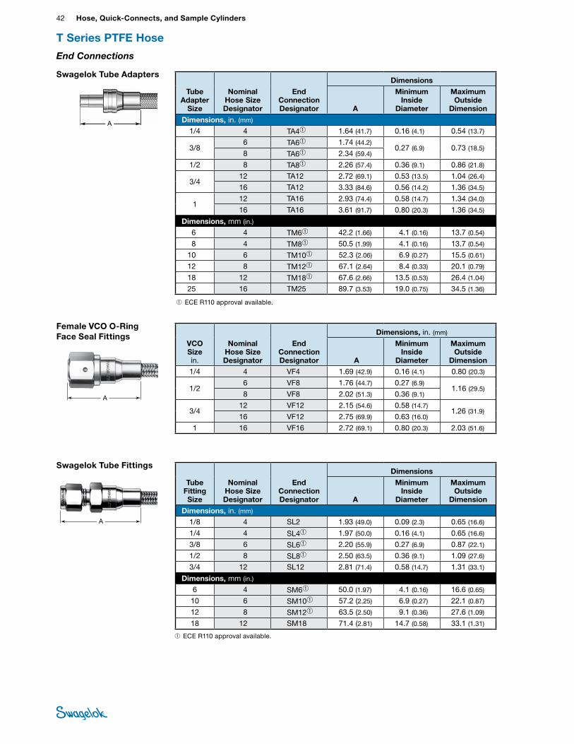
42 Hose, Quick-Connects, and Sample CylindersHO
SE /
FLEX
IBLE
TU
BING
Swagelok Tube Fittings
A
Tube Fitting Size
Nominal Hose Size Designator
End Connection Designator
Dimensions
A
Minimum Inside
Diameter
Maximum Outside
Dimension
Dimensions, in. (mm) 1/8 4 SL2 1.93 (49.0) 0.09 (2.3) 0.65 (16.6)
1/4 4 SL4➀ 1.97 (50.0) 0.16 (4.1) 0.65 (16.6)
3/8 6 SL6➀ 2.20 (55.9) 0.27 (6.9) 0.87 (22.1)
1/2 8 SL8➀ 2.50 (63.5) 0.36 (9.1) 1.09 (27.6)
3/4 12 SL12 2.81 (71.4) 0.58 (14.7) 1.31 (33.1)
Dimensions, mm (in.) 6 4 SM6➀ 50.0 (1.97) 4.1 (0.16) 16.6 (0.65)
10 6 SM10➀ 57.2 (2.25) 6.9 (0.27) 22.1 (0.87)
12 8 SM12➀ 63.5 (2.50) 9.1 (0.36) 27.6 (1.09)
18 12 SM18 71.4 (2.81) 14.7 (0.58) 33.1 (1.31)
Swagelok Tube Adapters
A
Tube Adapter
Size
Nominal Hose Size Designator
End Connection Designator
Dimensions
A
Minimum Inside
Diameter
Maximum Outside
Dimension
Dimensions, in. (mm) 1/4 4 TA4➀ 1.64 (41.7) 0.16 (4.1) 0.54 (13.7)
3/8 6 TA6➀ 1.74 (44.2)
0.27 (6.9) 0.73 (18.5) 8 TA6➀ 2.34 (59.4)
1/2 8 TA8➀ 2.26 (57.4) 0.36 (9.1) 0.86 (21.8)
3/4 12 TA12 2.72 (69.1) 0.53 (13.5) 1.04 (26.4)
16 TA12 3.33 (84.6) 0.56 (14.2) 1.36 (34.5)
1 12 TA16 2.93 (74.4) 0.58 (14.7) 1.34 (34.0)
16 TA16 3.61 (91.7) 0.80 (20.3) 1.36 (34.5)
Dimensions, mm (in.) 6 4 TM6➀ 42.2 (1.66) 4.1 (0.16) 13.7 (0.54)
8 4 TM8➀ 50.5 (1.99) 4.1 (0.16) 13.7 (0.54)
10 6 TM10➀ 52.3 (2.06) 6.9 (0.27) 15.5 (0.61)
12 8 TM12➀ 67.1 (2.64) 8.4 (0.33) 20.1 (0.79)
18 12 TM18➀ 67.6 (2.66) 13.5 (0.53) 26.4 (1.04)
25 16 TM25 89.7 (3.53) 19.0 (0.75) 34.5 (1.36)
Female VCO O-Ring Face Seal Fittings
A
VCO Size in.
Nominal Hose Size Designator
End Connection Designator
Dimensions, in. (mm)
A
Minimum Inside
Diameter
Maximum Outside
Dimension1/4 4 VF4 1.69 (42.9) 0.16 (4.1) 0.80 (20.3)
1/2 6 VF8 1.76 (44.7) 0.27 (6.9)
1.16 (29.5) 8 VF8 2.02 (51.3) 0.36 (9.1)
3/4 12 VF12 2.15 (54.6) 0.58 (14.7)
1.26 (31.9)16 VF12 2.75 (69.9) 0.63 (16.0)
1 16 VF16 2.72 (69.1) 0.80 (20.3) 2.03 (51.6)
T Series PTFE Hose
End Connections
➀ ECE R110 approval available.
➀ ECE R110 approval available.
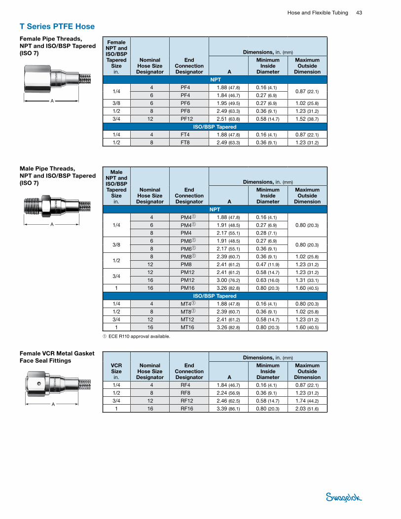
Hose and Flexible Tubing 43 HOSE /
FLEXIBLE TUBING
Male Pipe Threads, NPT and ISO/BSP Tapered (ISO 7)
A
Male NPT and ISO/BSP Tapered
Size in.
Nominal Hose Size Designator
End Connection Designator
Dimensions, in. (mm)
A
Minimum Inside
Diameter
Maximum Outside
Dimension
NPT
1/4
4 PM4➀ 1.88 (47.8) 0.16 (4.1)
0.80 (20.3) 6 PM4➀ 1.91 (48.5) 0.27 (6.9)
8 PM4 2.17 (55.1) 0.28 (7.1)
3/8 6 PM6➀ 1.91 (48.5) 0.27 (6.9)
0.80 (20.3) 8 PM6➀ 2.17 (55.1) 0.36 (9.1)
1/2 8 PM8➀ 2.39 (60.7) 0.36 (9.1) 1.02 (25.8)
12 PM8 2.41 (61.2) 0.47 (11.9) 1.23 (31.2)
3/4 12 PM12 2.41 (61.2) 0.58 (14.7) 1.23 (31.2)
16 PM12 3.00 (76.2) 0.63 (16.0) 1.31 (33.1)
1 16 PM16 3.26 (82.8) 0.80 (20.3) 1.60 (40.5)
ISO/BSP Tapered 1/4 4 MT4➀ 1.88 (47.8) 0.16 (4.1) 0.80 (20.3)
1/2 8 MT8➀ 2.39 (60.7) 0.36 (9.1) 1.02 (25.8)
3/4 12 MT12 2.41 (61.2) 0.58 (14.7) 1.23 (31.2)
1 16 MT16 3.26 (82.8) 0.80 (20.3) 1.60 (40.5)
Female Pipe Threads, NPT and ISO/BSP Tapered (ISO 7)
A
Female NPT and ISO/BSP Tapered
Size in.
Nominal Hose Size Designator
End Connection Designator
Dimensions, in. (mm)
A
Minimum Inside
Diameter
Maximum Outside
Dimension
NPT
1/4 4 PF4 1.88 (47.8) 0.16 (4.1)
0.87 (22.1) 6 PF4 1.84 (46.7) 0.27 (6.9)
3/8 6 PF6 1.95 (49.5) 0.27 (6.9) 1.02 (25.8)
1/2 8 PF8 2.49 (63.3) 0.36 (9.1) 1.23 (31.2)
3/4 12 PF12 2.51 (63.8) 0.58 (14.7) 1.52 (38.7)
ISO/BSP Tapered 1/4 4 FT4 1.88 (47.8) 0.16 (4.1) 0.87 (22.1)
1/2 8 FT8 2.49 (63.3) 0.36 (9.1) 1.23 (31.2)
T Series PTFE Hose
Female VCR Metal Gasket Face Seal Fittings
A
VCR Size in.
Nominal Hose Size Designator
End Connection Designator
Dimensions, in. (mm)
A
Minimum Inside
Diameter
Maximum Outside
Dimension1/4 4 RF4 1.84 (46.7) 0.16 (4.1) 0.87 (22.1)
1/2 8 RF8 2.24 (56.9) 0.36 (9.1) 1.23 (31.2)
3/4 12 RF12 2.46 (62.5) 0.58 (14.7) 1.74 (44.2)
1 16 RF16 3.39 (86.1) 0.80 (20.3) 2.03 (51.6)
➀ ECE R110 approval available.
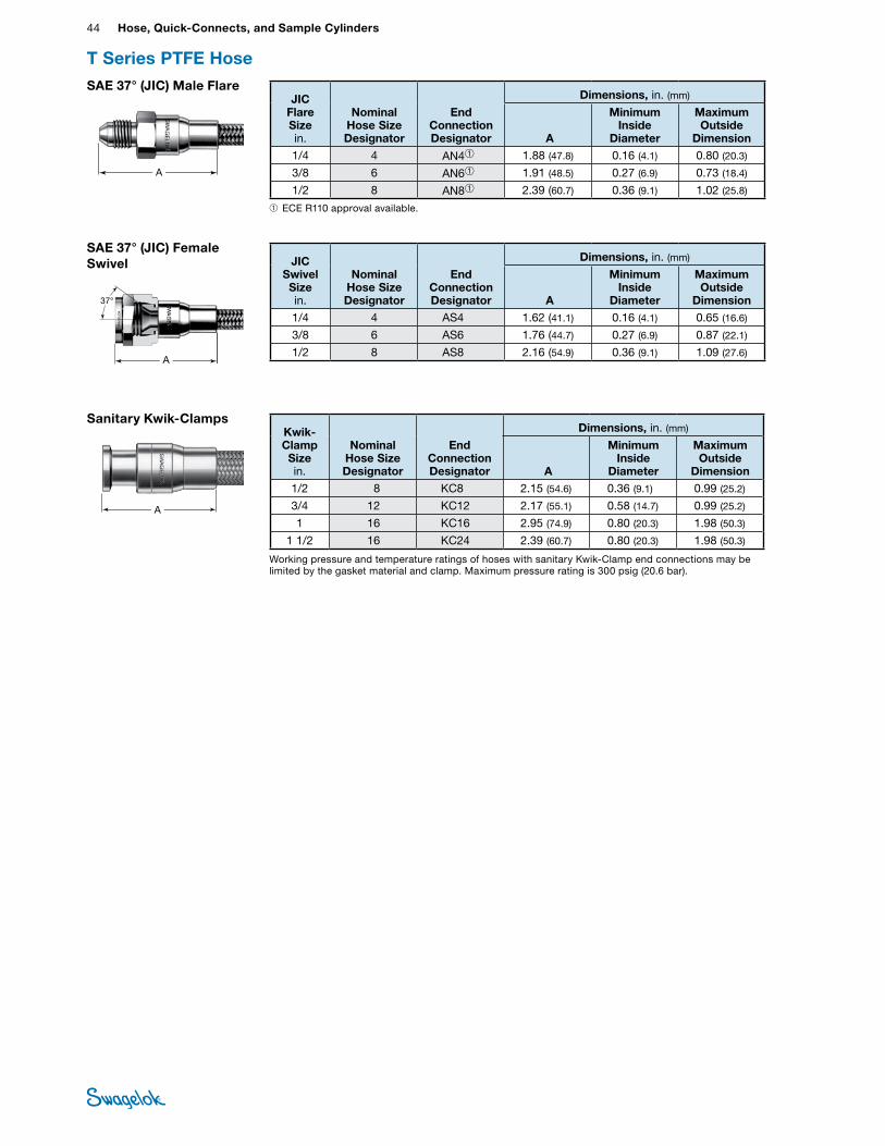
44 Hose, Quick-Connects, and Sample CylindersHO
SE /
FLEX
IBLE
TU
BING
A
Working pressure and temperature ratings of hoses with sanitary Kwik-Clamp end connections may be limited by the gasket material and clamp. Maximum pressure rating is 300 psig (20.6 bar).
Sanitary Kwik-ClampsKwik-Clamp Size in.
Nominal Hose Size Designator
End Connection Designator
Dimensions, in. (mm)
A
Minimum Inside
Diameter
Maximum Outside
Dimension1/2 8 KC8 2.15 (54.6) 0.36 (9.1) 0.99 (25.2)
3/4 12 KC12 2.17 (55.1) 0.58 (14.7) 0.99 (25.2)
1 16 KC16 2.95 (74.9) 0.80 (20.3) 1.98 (50.3)
1 1/2 16 KC24 2.39 (60.7) 0.80 (20.3) 1.98 (50.3)
SAE 37° (JIC) Female Swivel
PTFE hose image update with dimension lines
AS
A
JIC Swivel Size in.
Nominal Hose Size Designator
End Connection Designator
Dimensions, in. (mm)
A
Minimum Inside
Diameter
Maximum Outside
Dimension1/4 4 AS4 1.62 (41.1) 0.16 (4.1) 0.65 (16.6)
3/8 6 AS6 1.76 (44.7) 0.27 (6.9) 0.87 (22.1)
1/2 8 AS8 2.16 (54.9) 0.36 (9.1) 1.09 (27.6)
A
SAE 37° (JIC) Male FlareJIC
Flare Size in.
Nominal Hose Size Designator
End Connection Designator
Dimensions, in. (mm)
A
Minimum Inside
Diameter
Maximum Outside
Dimension1/4 4 AN4➀ 1.88 (47.8) 0.16 (4.1) 0.80 (20.3)
3/8 6 AN6➀ 1.91 (48.5) 0.27 (6.9) 0.73 (18.4)
1/2 8 AN8➀ 2.39 (60.7) 0.36 (9.1) 1.02 (25.8)
T Series PTFE Hose
➀ ECE R110 approval available.
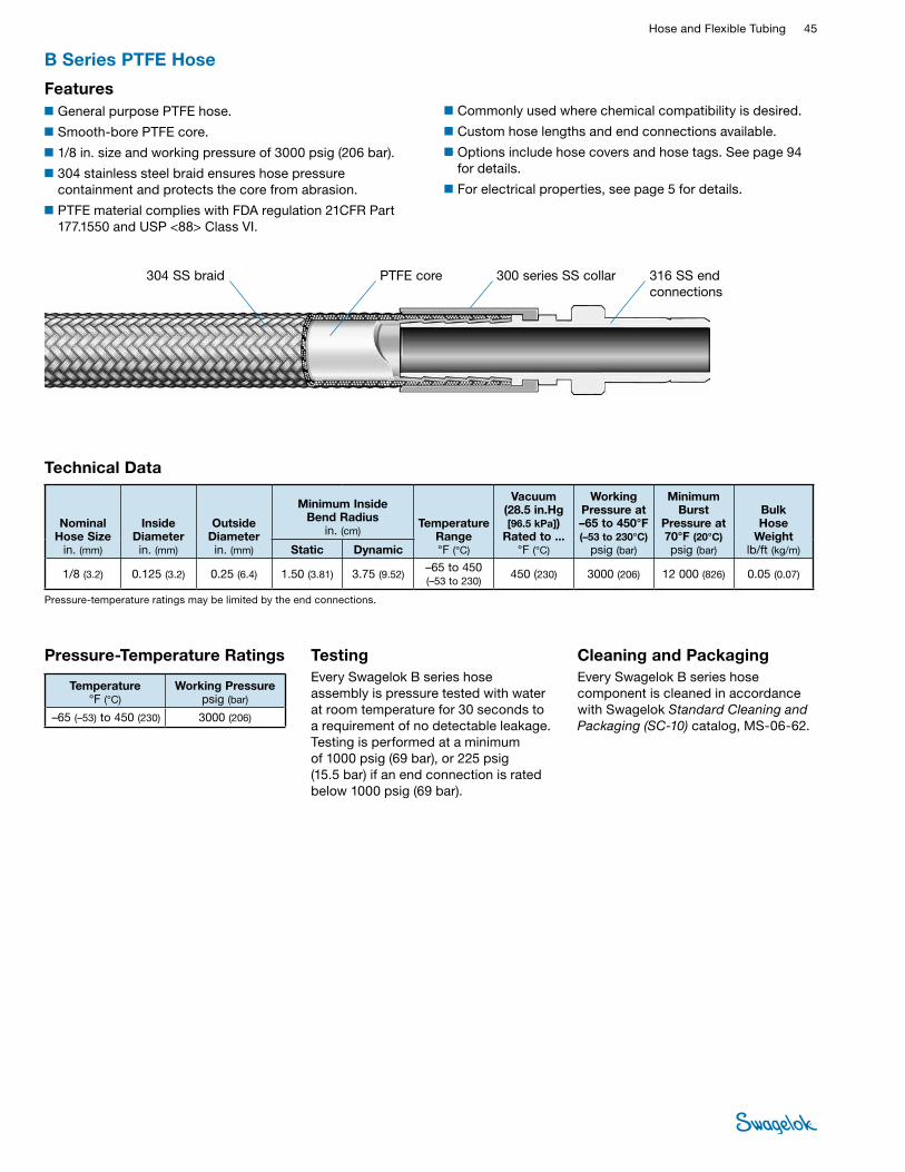
Hose and Flexible Tubing 45 HOSE /
FLEXIBLE TUBING
B Series PTFE Hose
■General purpose PTFE hose.
■Smooth-bore PTFE core.
■1/8 in. size and working pressure of 3000 psig (206 bar).
■304 stainless steel braid ensures hose pressure containment and protects the core from abrasion.
■PTFE material complies with FDA regulation 21CFR Part 177.1550 and USP <88> Class VI.
Features
304 SS braid PTFE core 316 SS end connections
■Commonly used where chemical compatibility is desired.
■Custom hose lengths and end connections available.
■Options include hose covers and hose tags. See page 94 for details.
■For electrical properties, see page 5 for details.
300 series SS collar
Testing Every Swagelok B series hose assembly is pressure tested with water at room temperature for 30 seconds to a requirement of no detectable leakage. Testing is performed at a minimum of 1000 psig (69 bar), or 225 psig (15.5 bar) if an end connection is rated below 1000 psig (69 bar).
Cleaning and PackagingEvery Swagelok B series hose component is cleaned in accordance with Swagelok Standard Cleaning and Packaging (SC‑10) catalog, MS-06-62.
Temperature °F (°C)
Working Pressure psig (bar)
–65 (–53) to 450 (230) 3000 (206)
Pressure-Temperature Ratings
Technical Data
Nominal Hose Size
in. (mm)
Inside Diameter in. (mm)
Outside Diameter in. (mm)
Minimum Inside Bend Radius
in. (cm)Temperature
Range °F (°C)
Vacuum (28.5 in.Hg [96.5 kPa])
Rated to ...°F (°C)
Working Pressure at –65 to 450°F (–53 to 230°C)
psig (bar)
Minimum Burst
Pressure at70°F (20°C) psig (bar)
Bulk Hose
Weightlb/ft (kg/m)Static Dynamic
1/8 (3.2) 0.125 (3.2) 0.25 (6.4) 1.50 (3.81) 3.75 (9.52)–65 to 450 (–53 to 230)
450 (230) 3000 (206) 12 000 (826) 0.05 (0.07)
Pressure-temperature ratings may be limited by the end connections.
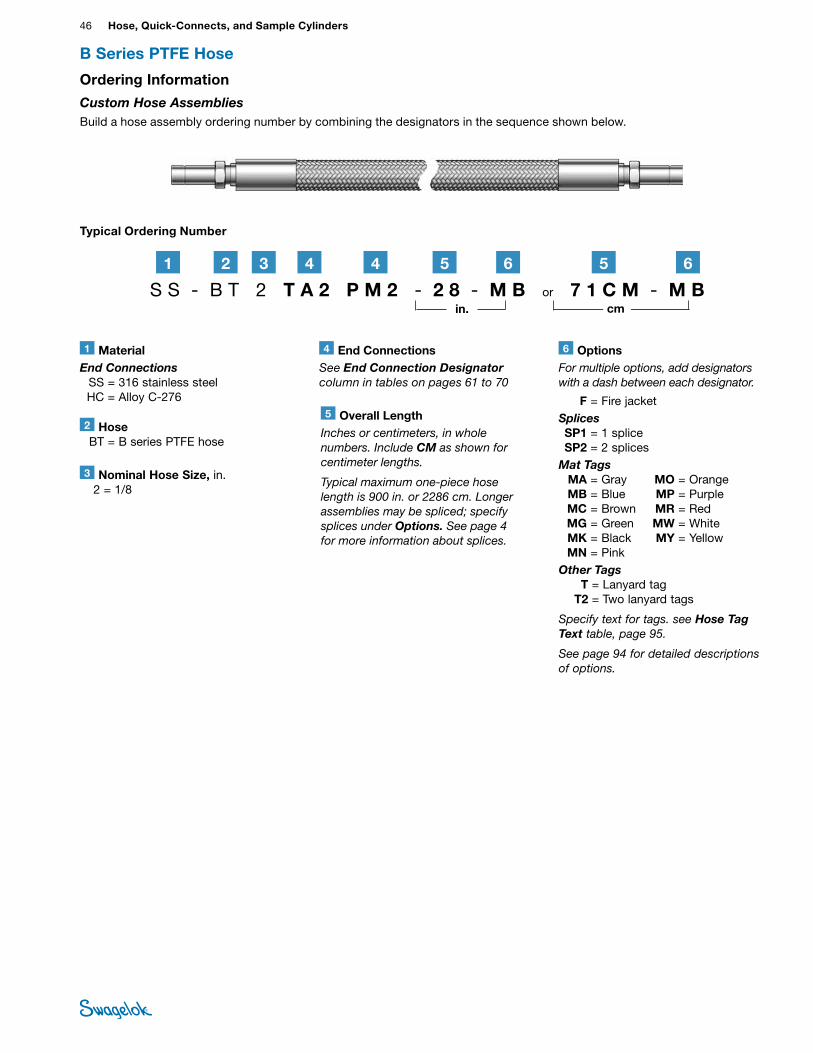
46 Hose, Quick-Connects, and Sample CylindersHO
SE /
FLEX
IBLE
TU
BING
B Series PTFE Hose
Typical Ordering Number
6 OptionsFor multiple options, add designators with a dash between each designator.
F = Fire jacketSplices SP1 = 1 splice SP2 = 2 splicesMat Tags MA = Gray MO = Orange MB = Blue MP = Purple MC = Brown MR = Red MG = Green MW = White MK = Black MY = Yellow MN = PinkOther Tags T = Lanyard tag T2 = Two lanyard tags
Specify text for tags. see Hose Tag Text table, page 95.
See page 94 for detailed descriptions of options.
4 End ConnectionsSee End Connection Designator column in tables on pages 61 to 70
3 Nominal Hose Size, in. 2 = 1/8
2 Hose BT = B series PTFE hose
5 Overall LengthInches or centimeters, in whole numbers. Include CM as shown for centimeter lengths.
Typical maximum one‑piece hose length is 900 in. or 2286 cm. Longer assemblies may be spliced; specify splices under Options. See page 4 for more information about splices.
1 MaterialEnd Connections SS = 316 stainless steel HC = Alloy C-276
S S - B T 2 T A 2 P M 2 - 2 8 - M B or 7 1 C M - M B21 3 4 4 5 6 5 6
in. cm
Ordering Information
Custom Hose AssembliesBuild a hose assembly ordering number by combining the designators in the sequence shown below.
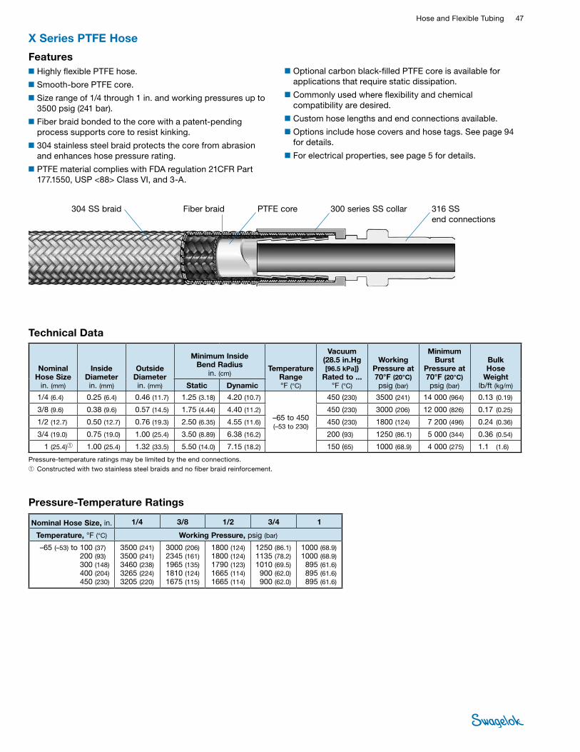
Hose and Flexible Tubing 47 HOSE /
FLEXIBLE TUBING
■Optional carbon black-filled PTFE core is available for applications that require static dissipation.
■Commonly used where flexibility and chemical compatibility are desired.
■Custom hose lengths and end connections available.
■Options include hose covers and hose tags. See page 94 for details.
■For electrical properties, see page 5 for details.
X Series PTFE Hose
■Highly flexible PTFE hose.
■Smooth-bore PTFE core.
■Size range of 1/4 through 1 in. and working pressures up to 3500 psig (241 bar).
■Fiber braid bonded to the core with a patent-pending process supports core to resist kinking.
■304 stainless steel braid protects the core from abrasion and enhances hose pressure rating.
■PTFE material complies with FDA regulation 21CFR Part 177.1550, USP <88> Class VI, and 3-A.
Features
304 SS braid PTFE coreFiber braid 316 SS end connections
300 series SS collar
Technical Data
Nominal Hose Size
in. (mm)
Inside Diameter in. (mm)
Outside Diameter in. (mm)
Minimum Inside Bend Radius
in. (cm) Temperature
Range °F (°C)
Vacuum (28.5 in.Hg [96.5 kPa])
Rated to ...°F (°C)
Working Pressure at 70°F (20°C) psig (bar)
Minimum Burst
Pressure at70°F (20°C) psig (bar)
Bulk Hose
Weightlb/ft (kg/m)Static Dynamic
1/4 (6.4) 0.25 (6.4) 0.46 (11.7) 1.25 (3.18) 4.20 (10.7)
–65 to 450 (–53 to 230)
450 (230) 3500 (241) 14 000 (964) 0.13 (0.19)
3/8 (9.6) 0.38 (9.6) 0.57 (14.5) 1.75 (4.44) 4.40 (11.2) 450 (230) 3000 (206) 12 000 (826) 0.17 (0.25)
1/2 (12.7) 0.50 (12.7) 0.76 (19.3) 2.50 (6.35) 4.55 (11.6) 450 (230) 1800 (124) 7 200 (496) 0.24 (0.36)
3/4 (19.0) 0.75 (19.0) 1.00 (25.4) 3.50 (8.89) 6.38 (16.2) 200 (93) 1250 (86.1) 5 000 (344) 0.36 (0.54)
1 (25.4)➀ 1.00 (25.4) 1.32 (33.5) 5.50 (14.0) 7.15 (18.2) 150 (65) 1000 (68.9) 4 000 (275) 1.1 (1.6)
Pressure-temperature ratings may be limited by the end connections. ➀ Constructed with two stainless steel braids and no fiber braid reinforcement.
Pressure-Temperature Ratings
Nominal Hose Size, in. 1/4 3/8 1/2 3/4 1
Temperature, °F (°C) Working Pressure, psig (bar)
–65 (–53) to 100 (37)200 (93)
300 (148) 400 (204) 450 (230)
3500 (241) 3500 (241)3460 (238)3265 (224)3205 (220)
3000 (206)2345 (161) 1965 (135)1810 (124)1675 (115)
1800 (124)1800 (124) 1790 (123)1665 (114)1665 (114)
1250 (86.1)1135 (78.2)1010 (69.5)900 (62.0)900 (62.0)
1000 (68.9)1000 (68.9)895 (61.6)895 (61.6)895 (61.6)
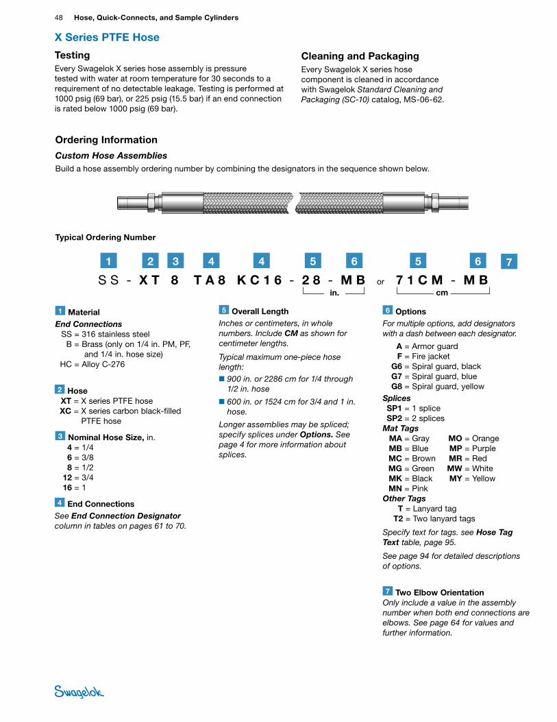
48 Hose, Quick-Connects, and Sample CylindersHO
SE /
FLEX
IBLE
TU
BING
Cleaning and PackagingEvery Swagelok X series hose component is cleaned in accordance with Swagelok Standard Cleaning and Packaging (SC‑10) catalog, MS-06-62.
TestingEvery Swagelok X series hose assembly is pressure tested with water at room temperature for 30 seconds to a requirement of no detectable leakage. Testing is performed at 1000 psig (69 bar), or 225 psig (15.5 bar) if an end connection is rated below 1000 psig (69 bar).
X Series PTFE Hose
3 Nominal Hose Size, in. 4 = 1/4 6 = 3/8 8 = 1/2 12 = 3/4 16 = 1
2 Hose XT = X series PTFE hose XC = X series carbon black-filled
PTFE hose
Typical Ordering Number
1 MaterialEnd Connections SS = 316 stainless steel B = Brass (only on 1/4 in. PM, PF,
and 1/4 in. hose size) HC = Alloy C-276
S S - X T 8 T A 8 K C 1 6 - 2 8 - M B or 7 1 C M - M B
21 3 4 4
6 OptionsFor multiple options, add designators with a dash between each designator.
A = Armor guard F = Fire jacket G6 = Spiral guard, black G7 = Spiral guard, blue G8 = Spiral guard, yellowSplices SP1 = 1 splice SP2 = 2 splicesMat Tags MA = Gray MO = Orange MB = Blue MP = Purple MC = Brown MR = Red MG = Green MW = White MK = Black MY = Yellow MN = PinkOther Tags T = Lanyard tag T2 = Two lanyard tags
Specify text for tags. see Hose Tag Text table, page 95.
See page 94 for detailed descriptions of options.
5 6 5 6
Ordering Information
Custom Hose AssembliesBuild a hose assembly ordering number by combining the designators in the sequence shown below.
in. cm
4 End ConnectionsSee End Connection Designator column in tables on pages 61 to 70.
5 Overall LengthInches or centimeters, in whole numbers. Include CM as shown for centimeter lengths.
Typical maximum one‑piece hose length:■900 in. or 2286 cm for 1/4 through
1/2 in. hose
■600 in. or 1524 cm for 3/4 and 1 in. hose.
Longer assemblies may be spliced; specify splices under Options. See page 4 for more information about splices.
7 Two Elbow OrientationOnly include a value in the assembly number when both end connections are elbows. See page 64 for values and further information.
7
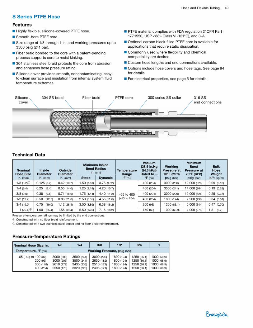
Hose and Flexible Tubing 49 HOSE /
FLEXIBLE TUBING
■PTFE material complies with FDA regulation 21CFR Part 177.1550, USP <88> Class VI (121°C), and 3-A.
■Optional carbon black-filled PTFE core is available for applications that require static dissipation.
■Commonly used where flexibility and chemical compatibility are desired.
■Custom hose lengths and end connections available.
■Options include hose covers and hose tags. See page 94 for details.
■For electrical properties, see page 5 for details.
S Series PTFE Hose
■Highly flexible, silicone-covered PTFE hose.
■Smooth-bore PTFE core.
■Size range of 1/8 through 1 in. and working pressures up to 3500 psig (241 bar).
■Fiber braid bonded to the core with a patent-pending process supports core to resist kinking.
■304 stainless steel braid protects the core from abrasion and enhances hose pressure rating.
■Silicone cover provides smooth, noncontaminating, easy-to-clean surface and insulation from internal system fluid temperature extremes.
Features
Technical Data
Nominal Hose Size
in. (mm)
Inside Diameter in. (mm)
Outside Diameter in. (mm)
Minimum Inside Bend Radius
in. (cm) Temperature
Range °F (°C)
Vacuum (28.5 in.Hg [96.5 kPa])
Rated to ...°F (°C)
Working Pressure at 70°F (20°C) psig (bar)
Minimum Burst
Pressure at70°F (20°C) psig (bar)
Bulk Hose
Weightlb/ft (kg/m)Static Dynamic
1/8 (3.2)➀ 0.125 (3.2) 0.42 (10.7) 1.50 (3.81) 3.75 (9.52)
–65 to 400 (–53 to 204)
400 (204) 3000 (206) 12 000 (826) 0.09 (0.13)
1/4 (6.4) 0.25 (6.4) 0.55 (14.0) 1.25 (3.18) 4.20 (10.7) 400 (204) 3500 (241) 14 000 (964) 0.19 (0.28)
3/8 (9.6) 0.38 (9.6) 0.71 (18.0) 1.75 (4.44) 4.40 (11.2) 400 (204) 3000 (206) 12 000 (826) 0.25 (0.37)
1/2 (12.7) 0.50 (12.7) 0.86 (21.8) 2.50 (6.35) 4.55 (11.6) 400 (204) 1800 (124) 7 200 (496) 0.34 (0.51)
3/4 (19.0) 0.75 (19.0) 1.12 (28.4) 3.50 (8.89) 6.38 (16.2) 200 (93) 1250 (86.1) 5 000 (344) 0.47 (0.70)
1 (25.4)➁ 1.00 (25.4) 1.55 (39.4) 5.50 (14.0) 7.15 (18.2) 150 (65) 1000 (68.9) 4 000 (275) 1.8 (2.7)
Pressure-temperature ratings may be limited by the end connections. ➀Constructed with no fiber braid reinforcement.➁ Constructed with two stainless steel braids and no fiber braid reinforcement.
PTFE coreFiber braidSilicone cover
304 SS braid 316 SS end connections
300 series SS collar
Pressure-Temperature Ratings
Nominal Hose Size, in. 1/8 1/4 3/8 1/2 3/4 1
Temperature, °F (°C) Working Pressure, psig (bar)
–65 (–53) to 100 (37)200 (93)
300 (148) 400 (204)
3000 (206)3000 (206) 2610 (179) 2550 (175)
3500 (241) 3500 (241)3435 (236)3320 (228)
3000 (206)2650 (182) 2510 (172)2495 (171)
1800 (124)1800 (124) 1800 (124)1800 (124)
1250 (86.1)1250 (86.1)1250 (86.1) 1250 (86.1)
1000 (68.9)1000 (68.9)1000 (68.9)1000 (68.9)
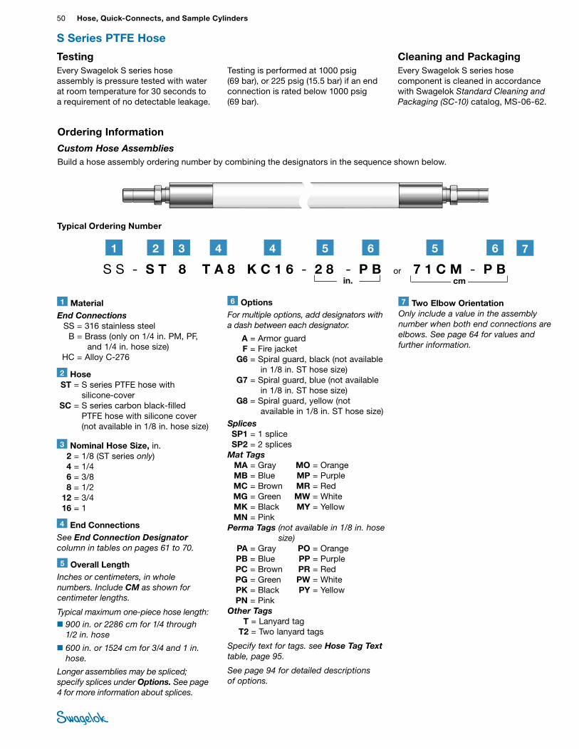
50 Hose, Quick-Connects, and Sample CylindersHO
SE /
FLEX
IBLE
TU
BING
TestingEvery Swagelok S series hose assembly is pressure tested with water at room temperature for 30 seconds to a requirement of no detectable leakage.
Testing is performed at 1000 psig (69 bar), or 225 psig (15.5 bar) if an end connection is rated below 1000 psig (69 bar).
S Series PTFE Hose
Typical Ordering Number
S S - S T 8 T A 8 K C 1 6 - 2 8 - P B or 7 1 C M - P B
21 3 4 4 5 6 5 6
3 Nominal Hose Size, in. 2 = 1/8 (ST series only) 4 = 1/4 6 = 3/8 8 = 1/2 12 = 3/4 16 = 1
2 Hose ST = S series PTFE hose with
silicone-cover SC = S series carbon black-filled
PTFE hose with silicone cover (not available in 1/8 in. hose size)
1 MaterialEnd Connections SS = 316 stainless steel B = Brass (only on 1/4 in. PM, PF,
and 1/4 in. hose size) HC = Alloy C-276
Ordering Information
Custom Hose AssembliesBuild a hose assembly ordering number by combining the designators in the sequence shown below.
in. cm
6 OptionsFor multiple options, add designators with a dash between each designator.
A = Armor guard F = Fire jacket G6 = Spiral guard, black (not available
in 1/8 in. ST hose size) G7 = Spiral guard, blue (not available
in 1/8 in. ST hose size) G8 = Spiral guard, yellow (not
available in 1/8 in. ST hose size)Splices SP1 = 1 splice SP2 = 2 splicesMat Tags MA = Gray MO = Orange MB = Blue MP = Purple MC = Brown MR = Red MG = Green MW = White MK = Black MY = Yellow MN = PinkPerma Tags (not available in 1/8 in. hose
size) PA = Gray PO = Orange PB = Blue PP = Purple PC = Brown PR = Red PG = Green PW = White PK = Black PY = Yellow PN = PinkOther Tags T = Lanyard tag T2 = Two lanyard tags
Specify text for tags. see Hose Tag Text table, page 95.
See page 94 for detailed descriptions of options.
4 End ConnectionsSee End Connection Designator column in tables on pages 61 to 70.
5 Overall LengthInches or centimeters, in whole numbers. Include CM as shown for centimeter lengths.
Typical maximum one‑piece hose length:■900 in. or 2286 cm for 1/4 through
1/2 in. hose
■600 in. or 1524 cm for 3/4 and 1 in. hose.
Longer assemblies may be spliced; specify splices under Options. See page 4 for more information about splices.
Cleaning and PackagingEvery Swagelok S series hose component is cleaned in accordance with Swagelok Standard Cleaning and Packaging (SC‑10) catalog, MS-06-62.
7 Two Elbow OrientationOnly include a value in the assembly number when both end connections are elbows. See page 64 for values and further information.
7
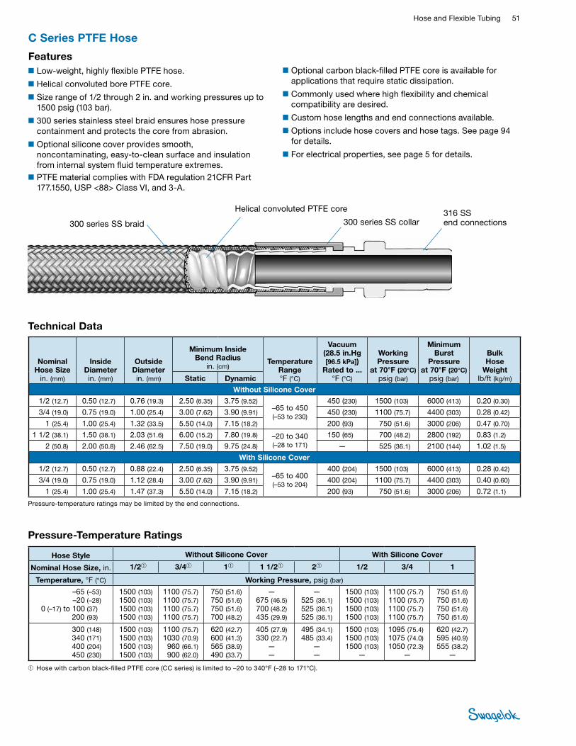
Hose and Flexible Tubing 51 HOSE /
FLEXIBLE TUBING
■Optional carbon black-filled PTFE core is available for applications that require static dissipation.
■Commonly used where high flexibility and chemical compatibility are desired.
■Custom hose lengths and end connections available.
■Options include hose covers and hose tags. See page 94 for details.
■For electrical properties, see page 5 for details.
C Series PTFE Hose
■Low-weight, highly flexible PTFE hose.
■Helical convoluted bore PTFE core.
■Size range of 1/2 through 2 in. and working pressures up to 1500 psig (103 bar).
■300 series stainless steel braid ensures hose pressure containment and protects the core from abrasion.
■Optional silicone cover provides smooth, noncontaminating, easy-to-clean surface and insulation from internal system fluid temperature extremes.
■PTFE material complies with FDA regulation 21CFR Part 177.1550, USP <88> Class VI, and 3-A.
Features
Technical Data
Nominal Hose Size
in. (mm)
Inside Diameter in. (mm)
Outside Diameter in. (mm)
Minimum Inside Bend Radius
in. (cm) Temperature
Range °F (°C)
Vacuum (28.5 in.Hg [96.5 kPa])
Rated to ...°F (°C)
Working Pressure
at 70°F (20°C) psig (bar)
Minimum Burst
Pressure at 70°F (20°C)
psig (bar)
Bulk Hose
Weightlb/ft (kg/m)Static Dynamic
Without Silicone Cover
1/2 (12.7) 0.50 (12.7) 0.76 (19.3) 2.50 (6.35) 3.75 (9.52)–65 to 450 (–53 to 230)
450 (230) 1500 (103) 6000 (413) 0.20 (0.30)
3/4 (19.0) 0.75 (19.0) 1.00 (25.4) 3.00 (7.62) 3.90 (9.91) 450 (230) 1100 (75.7) 4400 (303) 0.28 (0.42)
1 (25.4) 1.00 (25.4) 1.32 (33.5) 5.50 (14.0) 7.15 (18.2) 200 (93) 750 (51.6) 3000 (206) 0.47 (0.70)
1 1/2 (38.1) 1.50 (38.1) 2.03 (51.6) 6.00 (15.2) 7.80 (19.8) –20 to 340 (–28 to 171)
150 (65) 700 (48.2) 2800 (192) 0.83 (1.2)
2 (50.8) 2.00 (50.8) 2.46 (62.5) 7.50 (19.0) 9.75 (24.8) — 525 (36.1) 2100 (144) 1.02 (1.5)
With Silicone Cover
1/2 (12.7) 0.50 (12.7) 0.88 (22.4) 2.50 (6.35) 3.75 (9.52)–65 to 400 (–53 to 204)
400 (204) 1500 (103) 6000 (413) 0.28 (0.42)
3/4 (19.0) 0.75 (19.0) 1.12 (28.4) 3.00 (7.62) 3.90 (9.91) 400 (204) 1100 (75.7) 4400 (303) 0.40 (0.60)
1 (25.4) 1.00 (25.4) 1.47 (37.3) 5.50 (14.0) 7.15 (18.2) 200 (93) 750 (51.6) 3000 (206) 0.72 (1.1)
Pressure-temperature ratings may be limited by the end connections.
300 series SS braid
Helical convoluted PTFE core 316 SS end connections300 series SS collar
Pressure-Temperature Ratings
Hose Style Without Silicone Cover With Silicone Cover
Nominal Hose Size, in. 1/2➀ 3/4➀ 1➀ 1 1/2➀ 2➀ 1/2 3/4 1
Temperature, °F (°C) Working Pressure, psig (bar)
–65 (–53)–20 (–28)
0 (–17) to 100 (37)200 (93)
1500 (103)1500 (103) 1500 (103)1500 (103)
1100 (75.7)1100 (75.7) 1100 (75.7) 1100 (75.7)
750 (51.6)750 (51.6)750 (51.6)700 (48.2)
—675 (46.5)700 (48.2) 435 (29.9)
— 525 (36.1)525 (36.1)525 (36.1)
1500 (103)1500 (103)1500 (103)1500 (103)
1100 (75.7) 1100 (75.7) 1100 (75.7) 1100 (75.7)
750 (51.6)750 (51.6)750 (51.6)750 (51.6)
300 (148) 340 (171)400 (204) 450 (230)
1500 (103) 1500 (103) 1500 (103)1500 (103)
1100 (75.7) 1030 (70.9)960 (66.1)900 (62.0)
620 (42.7)600 (41.3)565 (38.9)490 (33.7)
405 (27.9)330 (22.7)
——
495 (34.1)485 (33.4)
——
1500 (103)1500 (103)1500 (103)
—
1095 (75.4)1075 (74.0)1050 (72.3)
—
620 (42.7)595 (40.9)555 (38.2)
—
➀ Hose with carbon black-filled PTFE core (CC series) is limited to –20 to 340°F (–28 to 171°C).
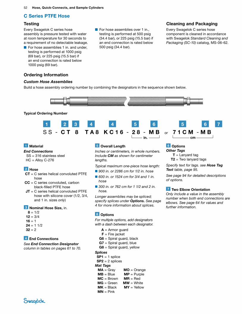
52 Hose, Quick-Connects, and Sample CylindersHO
SE /
FLEX
IBLE
TU
BING
Testing Every Swagelok C series hose assembly is pressure tested with water at room temperature for 30 seconds to a requirement of no detectable leakage.■ For hose assemblies 1 in. and under,
testing is performed at 1000 psig (69 bar), or 225 psig (15.5 bar) if an end connection is rated below 1000 psig (69 bar).
Cleaning and PackagingEvery Swagelok C series hose component is cleaned in accordance with Swagelok Standard Cleaning and Packaging (SC‑10) catalog, MS-06-62.
C Series PTFE Hose
Typical Ordering Number
S S - C T 8 T A 8 K C 1 6 - 2 8 - M B or 7 1 C M - M B 21 3 4 4 5 6 5 6
2 Hose CT = C series helical convoluted PTFE
hose CC = C series convoluted, carbon
black-filled PTFE hose JT = C series helical convoluted PTFE
hose with silicone cover (1/2, 3/4, and 1 in. sizes only)
1 MaterialEnd Connections SS = 316 stainless steel HC = Alloy C-276
3 Nominal Hose Size, in. 8 = 1/2 12 = 3/4 16 = 1 24 = 1 1/2 32 = 2
Ordering Information
Custom Hose AssembliesBuild a hose assembly ordering number by combining the designators in the sequence shown below.
in. cm
6 OptionsFor multiple options, add designators with a dash between each designator.
A = Armor guard F = Fire jacket G6 = Spiral guard, black G7 = Spiral guard, blue G8 = Spiral guard, yellowSplices SP1 = 1 splice SP2 = 2 splicesMat Tags MA = Gray MO = Orange MB = Blue MP = Purple MC = Brown MR = Red MG = Green MW = White MK = Black MY = Yellow MN = Pink
4 End ConnectionsSee End Connection Designator column in tables on pages 61 to 70.
5 Overall LengthInches or centimeters, in whole numbers. Include CM as shown for centimeter lengths.
Typical maximum one‑piece hose length:■900 in. or 2286 cm for 1/2 in. hose
■600 in. or 1524 cm for 3/4 and 1 in. hose
■300 in. or 762 cm for 1 1/2 and 2 in. hose.
Longer assemblies may be spliced; specify splices under Options. See page 4 for more information about splices.
■ For hose assemblies over 1 in., testing is performed at 500 psig (34.4 bar), or 225 psig (15.5 bar) if an end connection is rated below 500 psig (34.4 bar).
7 Two Elbow OrientationOnly include a value in the assembly number when both end connections are elbows. See page 64 for values and further information.
7
6 OptionsOther Tags T = Lanyard tag T2 = Two lanyard tags
Specify text for tags. see Hose Tag Text table, page 95.
See page 94 for detailed descriptions of options.
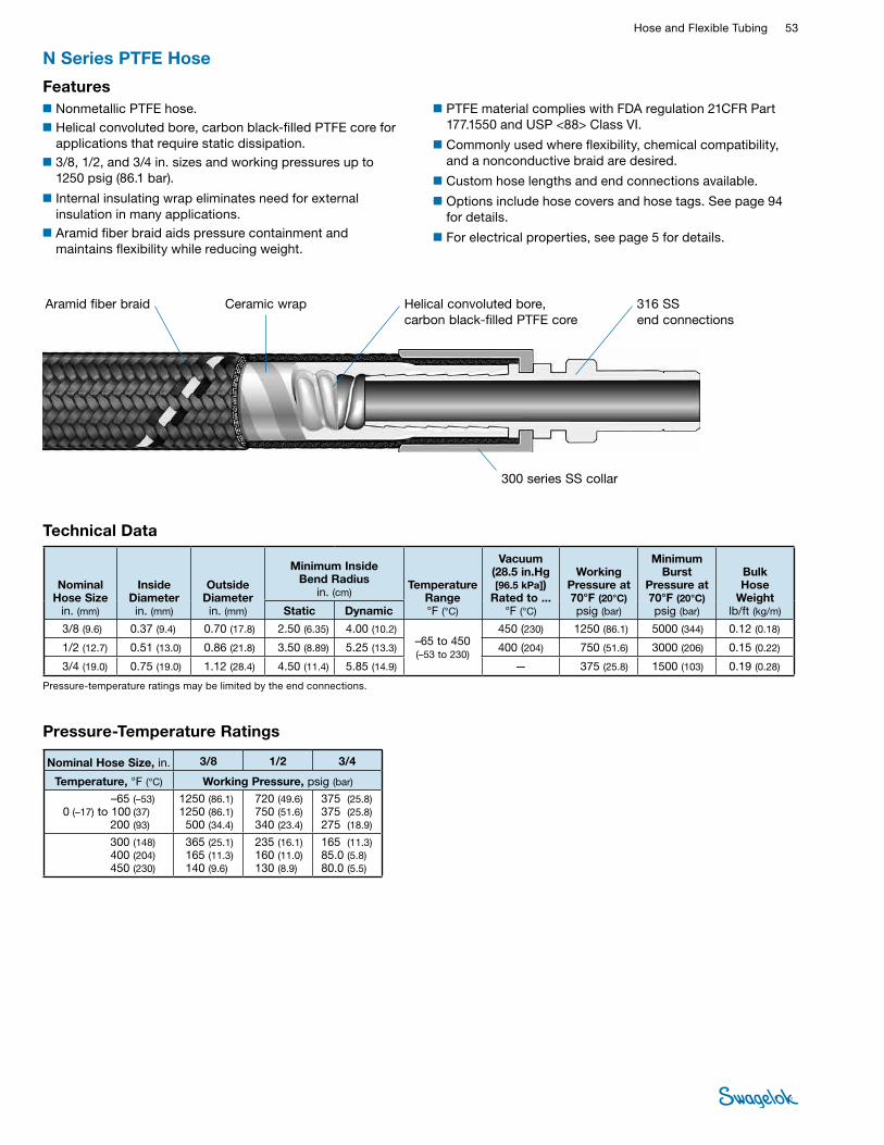
Hose and Flexible Tubing 53 HOSE /
FLEXIBLE TUBING
■PTFE material complies with FDA regulation 21CFR Part 177.1550 and USP <88> Class VI.
■Commonly used where flexibility, chemical compatibility, and a nonconductive braid are desired.
■Custom hose lengths and end connections available.
■Options include hose covers and hose tags. See page 94 for details.
■For electrical properties, see page 5 for details.
N Series PTFE Hose
■Nonmetallic PTFE hose. ■Helical convoluted bore, carbon black-filled PTFE core for
applications that require static dissipation.■3/8, 1/2, and 3/4 in. sizes and working pressures up to
1250 psig (86.1 bar).
■Internal insulating wrap eliminates need for external insulation in many applications.
■Aramid fiber braid aids pressure containment and maintains flexibility while reducing weight.
Features
Technical Data
Nominal Hose Size
in. (mm)
Inside Diameter in. (mm)
Outside Diameter in. (mm)
Minimum Inside Bend Radius
in. (cm) Temperature
Range °F (°C)
Vacuum (28.5 in.Hg [96.5 kPa])
Rated to ...°F (°C)
Working Pressure at 70°F (20°C) psig (bar)
Minimum Burst
Pressure at70°F (20°C) psig (bar)
Bulk Hose
Weightlb/ft (kg/m)Static Dynamic
3/8 (9.6) 0.37 (9.4) 0.70 (17.8) 2.50 (6.35) 4.00 (10.2)–65 to 450 (–53 to 230)
450 (230) 1250 (86.1) 5000 (344) 0.12 (0.18)
1/2 (12.7) 0.51 (13.0) 0.86 (21.8) 3.50 (8.89) 5.25 (13.3) 400 (204) 750 (51.6) 3000 (206) 0.15 (0.22)
3/4 (19.0) 0.75 (19.0) 1.12 (28.4) 4.50 (11.4) 5.85 (14.9) — 375 (25.8) 1500 (103) 0.19 (0.28)
Pressure-temperature ratings may be limited by the end connections.
Helical convoluted bore, carbon black-filled PTFE core
Aramid fiber braid Ceramic wrap 316 SS end connections
300 series SS collar
Pressure-Temperature Ratings
Nominal Hose Size, in. 3/8 1/2 3/4
Temperature, °F (°C) Working Pressure, psig (bar) –65 (–53)
0 (–17) to 100 (37)200 (93)
1250 (86.1) 1250 (86.1)500 (34.4)
720 (49.6) 750 (51.6) 340 (23.4)
375 (25.8) 375 (25.8) 275 (18.9)
300 (148) 400 (204) 450 (230)
365 (25.1) 165 (11.3) 140 (9.6)
235 (16.1)160 (11.0)130 (8.9)
165 (11.3) 85.0 (5.8) 80.0 (5.5)
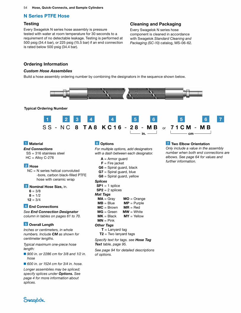
54 Hose, Quick-Connects, and Sample CylindersHO
SE /
FLEX
IBLE
TU
BING
Testing Every Swagelok N series hose assembly is pressure tested with water at room temperature for 30 seconds to a requirement of no detectable leakage. Testing is performed at 500 psig (34.4 bar), or 225 psig (15.5 bar) if an end connection is rated below 500 psig (34.4 bar).
Cleaning and PackagingEvery Swagelok N series hose component is cleaned in accordance with Swagelok Standard Cleaning and Packaging (SC‑10) catalog, MS-06-62.
3 Nominal Hose Size, in. 6 = 3/8 8 = 1/2 12 = 3/4
2 Hose NC = N series helical convoluted
-bore, carbon black-filled PTFE hose with ceramic wrap
Typical Ordering Number
1 MaterialEnd Connections SS = 316 stainless steel HC = Alloy C-276
S S - N C 8 T A 8 K C 1 6 - 2 8 - M B or 7 1 C M - M B
21 3 4 4 5 6 5 6
6 OptionsFor multiple options, add designators with a dash between each designator.
A = Armor guard F = Fire jacket G6 = Spiral guard, black G7 = Spiral guard, blue G8 = Spiral guard, yellowSplices SP1 = 1 splice SP2 = 2 splicesMat Tags MA = Gray MO = Orange MB = Blue MP = Purple MC = Brown MR = Red MG = Green MW = White MK = Black MY = Yellow MN = PinkOther Tags T = Lanyard tag T2 = Two lanyard tags
Specify text for tags. see Hose Tag Text table, page 95.
See page 94 for detailed descriptions of options.
N Series PTFE Hose
Ordering Information
Custom Hose AssembliesBuild a hose assembly ordering number by combining the designators in the sequence shown below.
in. cm
4 End ConnectionsSee End Connection Designator column in tables on pages 61 to 70.
5 Overall LengthInches or centimeters, in whole numbers. Include CM as shown for centimeter lengths.
Typical maximum one‑piece hose length:■900 in. or 2286 cm for 3/8 and 1/2 in.
hose
■600 in. or 1524 cm for 3/4 in. hose.
Longer assemblies may be spliced; specify splices under Options. See page 4 for more information about splices.
7 Two Elbow OrientationOnly include a value in the assembly number when both end connections are elbows. See page 64 for values and further information.
7
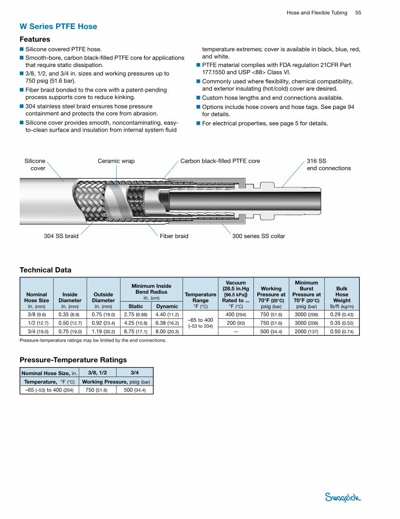
Hose and Flexible Tubing 55 HOSE /
FLEXIBLE TUBING
temperature extremes; cover is available in black, blue, red, and white.
■PTFE material complies with FDA regulation 21CFR Part 177.1550 and USP <88> Class VI.
■Commonly used where flexibility, chemical compatibility, and exterior insulating (hot/cold) cover are desired.
■Custom hose lengths and end connections available.
■Options include hose covers and hose tags. See page 94 for details.
■For electrical properties, see page 5 for details.
W Series PTFE Hose
■Silicone covered PTFE hose. ■Smooth-bore, carbon black-filled PTFE core for applications
that require static dissipation.■3/8, 1/2, and 3/4 in. sizes and working pressures up to
750 psig (51.6 bar).
■Fiber braid bonded to the core with a patent-pending process supports core to reduce kinking.
■304 stainless steel braid ensures hose pressure containment and protects the core from abrasion.
■Silicone cover provides smooth, noncontaminating, easy-to-clean surface and insulation from internal system fluid
Features
Technical Data
Nominal Hose Size
in. (mm)
Inside Diameter in. (mm)
Outside Diameter in. (mm)
Minimum Inside Bend Radius
in. (cm) Temperature
Range °F (°C)
Vacuum (28.5 in.Hg [96.5 kPa])
Rated to ...°F (°C)
Working Pressure at 70°F (20°C) psig (bar)
Minimum Burst
Pressure at70°F (20°C) psig (bar)
Bulk Hose
Weightlb/ft (kg/m)Static Dynamic
3/8 (9.6) 0.35 (8.9) 0.75 (19.0) 2.75 (6.98) 4.40 (11.2)–65 to 400 (–53 to 204)
400 (204) 750 (51.6) 3000 (206) 0.29 (0.43)
1/2 (12.7) 0.50 (12.7) 0.92 (23.4) 4.25 (10.8) 6.38 (16.2) 200 (93) 750 (51.6) 3000 (206) 0.35 (0.52)
3/4 (19.0) 0.75 (19.0) 1.19 (30.2) 6.75 (17.1) 8.00 (20.3) — 500 (34.4) 2000 (137) 0.50 (0.74)
Pressure-temperature ratings may be limited by the end connections.
Pressure-Temperature Ratings
Nominal Hose Size, in. 3/8, 1/2 3/4
Temperature, °F (°C) Working Pressure, psig (bar)
–65 (–53) to 400 (204) 750 (51.6) 500 (34.4)
Carbon black-filled PTFE core
Fiber braid
Silicone cover
304 SS braid
Ceramic wrap 316 SS end connections
300 series SS collar
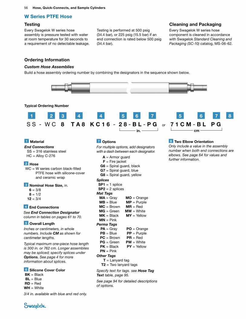
56 Hose, Quick-Connects, and Sample CylindersHO
SE /
FLEX
IBLE
TU
BING
Testing Every Swagelok W series hose assembly is pressure tested with water at room temperature for 30 seconds to a requirement of no detectable leakage.
Cleaning and PackagingEvery Swagelok W series hose component is cleaned in accordance with Swagelok Standard Cleaning and Packaging (SC‑10) catalog, MS-06-62.
W Series PTFE Hose
3 Nominal Hose Size, in. 6 = 3/8 8 = 1/2 12 = 3/4
2 Hose WC = W series carbon black-filled
PTFE hose with silicone-cover and ceramic wrap
Typical Ordering Number
1 MaterialEnd Connections SS = 316 stainless steel HC = Alloy C-276
S S - W C 8 T A 8 K C 1 6 - 2 8 - B L - P G or 7 1 C M - B L P G
21 3 4 4 5 6 5 6
6 Silicone Cover Color BK = Black BL = Blue RD = Red WH = White
3/4 in. available with blue and red only.
7 OptionsFor multiple options, add designators with a dash between each designator.
A = Armor guard F = Fire jacket G6 = Spiral guard, black G7 = Spiral guard, blue G8 = Spiral guard, yellowSplices SP1 = 1 splice SP2 = 2 splicesMat Tags MA = Gray MO = Orange MB = Blue MP = Purple MC = Brown MR = Red MG = Green MW = White MK = Black MY = Yellow MN = PinkPerma Tags PA = Gray PO = Orange PB = Blue PP = Purple PC = Brown PR = Red PG = Green PW = White PK = Black PY = Yellow PN = PinkOther Tags T = Lanyard tag T2 = Two lanyard tags
Specify text for tags. see Hose Tag Text table, page 95.
See page 94 for detailed descriptions of options.
77
in. cm
Ordering Information
Custom Hose AssembliesBuild a hose assembly ordering number by combining the designators in the sequence shown below.
4 End ConnectionsSee End Connection Designator column in tables on pages 61 to 70.
5 Overall LengthInches or centimeters, in whole numbers. Include CM as shown for centimeter lengths.
Typical maximum one‑piece hose length is 300 in. or 762 cm. Longer assemblies may be spliced; specify splices under Options. See page 4 for more information about splices.
Testing is performed at 500 psig (34.4 bar), or 225 psig (15.5 bar) if an end connection is rated below 500 psig (34.4 bar).
8 Two Elbow OrientationOnly include a value in the assembly number when both end connections are elbows. See page 64 for values and further information.
8
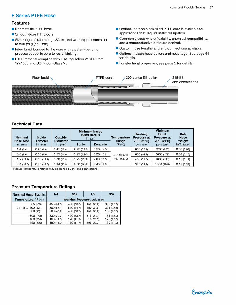
Hose and Flexible Tubing 57 HOSE /
FLEXIBLE TUBING
■Optional carbon black-filled PTFE core is available for applications that require static dissipation.
■Commonly used where flexibility, chemical compatibility, and a nonconductive braid are desired.
■Custom hose lengths and end connections available.
■Options include hose covers and hose tags. See page 94 for details.
■For electrical properties, see page 5 for details.
F Series PTFE Hose
■Nonmetallic PTFE hose.
■Smooth-bore PTFE core.
■Size range of 1/4 through 3/4 in. and working pressures up to 800 psig (55.1 bar).
■Fiber braid bonded to the core with a patent-pending process supports core to resist kinking.
■PTFE material complies with FDA regulation 21CFR Part 177.1550 and USP <88> Class VI.
Features
Technical Data
Nominal Hose Size
in. (mm)
Inside Diameter in. (mm)
Outside Diameter in. (mm)
Minimum Inside Bend Radius
in. (cm) Temperature Range °F (°C)
Working Pressure at 70°F (20°C) psig (bar)
Minimum Burst
Pressure at70°F (20°C) psig (bar)
Bulk Hose
Weightlb/ft (kg/m)Static Dynamic
1/4 (6.4) 0.25 (6.4) 0.41 (10.4) 2.75 (6.99) 5.50 (14.0)
–65 to 450 (–53 to 230)
800 (55.1) 3200 (220) 0.06 (0.09)
3/8 (9.6) 0.38 (9.6) 0.55 (14.0) 3.25 (8.26) 5.20 (13.2) 650 (44.7) 2600 (179) 0.09 (0.13)
1/2 (12.7) 0.50 (12.7) 0.70 (17.8) 5.25 (13.3) 7.88 (20.0) 450 (31.0) 1800 (124) 0.13 (0.19)
3/4 (19.0) 0.75 (19.0) 0.94 (23.9) 6.50 (16.5) 8.45 (21.5) 325 (22.3) 1300 (89.5) 0.18 (0.27)
Pressure-temperature ratings may be limited by the end connections.
Fiber braid PTFE core 316 SS end connections
Pressure-Temperature Ratings
Nominal Hose Size, in. 1/4 3/8 1/2 3/4
Temperature, °F (°C) Working Pressure, psig (bar)
–65 (–53) 0 (–17) to 100 (37)
200 (93)
455 (31.3) 800 (55.1) 700 (48.2)
480 (33.0) 650 (44.7)490 (33.7)
450 (31.0) 450 (31.0)450 (31.0)
325 (22.3)325 (22.3)185 (12.7)
300 (148) 400 (204) 450 (230)
330 (22.7)160 (11.0)160 (11.0)
490 (33.7)170 (11.7)170 (11.7)
315 (21.7)310 (21.3)295 (20.3)
175 (12.0) 175 (12.0)160 (11.0)
300 series SS collar
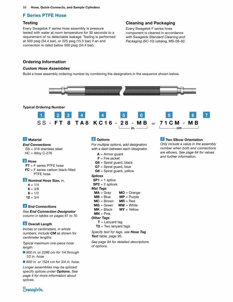
58 Hose, Quick-Connects, and Sample CylindersHO
SE /
FLEX
IBLE
TU
BING
Testing Every Swagelok F series hose assembly is pressure tested with water at room temperature for 30 seconds to a requirement of no detectable leakage. Testing is performed at 500 psig (34.4 bar), or 225 psig (15.5 bar) if an end connection is rated below 500 psig (34.4 bar).
Cleaning and PackagingEvery Swagelok F series hose component is cleaned in accordance with Swagelok Standard Cleaning and Packaging (SC‑10) catalog, MS-06-62.
F Series PTFE Hose
3 Nominal Hose Size, in. 4 = 1/4 6 = 3/8 8 = 1/2 12 = 3/4
2 Hose FT = F series PTFE hose FC = F series carbon black-filled
PTFE hose
Typical Ordering Number
1 MaterialEnd Connections SS = 316 stainless steel HC = Alloy C-276
S S - F T 8 T A 8 K C 1 6 - 2 8 - M B or 7 1 C M - M B 21 3 4 4
6 OptionsFor multiple options, add designators with a dash between each designator.
A = Armor guard F = Fire jacket G6 = Spiral guard, black G7 = Spiral guard, blue G8 = Spiral guard, yellowSplices SP1 = 1 splice SP2 = 2 splicesMat Tags MA = Gray MO = Orange MB = Blue MP = Purple MC = Brown MR = Red MG = Green MW = White MK = Black MY = Yellow MN = PinkOther Tags T = Lanyard tag T2 = Two lanyard tags
Specify text for tags. see Hose Tag Text table, page 95.
See page 94 for detailed descriptions of options.
5 6 5 6
Ordering Information
Custom Hose AssembliesBuild a hose assembly ordering number by combining the designators in the sequence shown below.
in. cm
4 End ConnectionsSee End Connection Designator column in tables on pages 61 to 70.
5 Overall LengthInches or centimeters, in whole numbers. Include CM as shown for centimeter lengths.
Typical maximum one‑piece hose length:■900 in. or 2286 cm for 1/4 through
1/2 in. hose
■600 in. or 1524 cm for 3/4 in. hose.
Longer assemblies may be spliced; specify splices under Options. See page 4 for more information about splices.
7 Two Elbow OrientationOnly include a value in the assembly number when both end connections are elbows. See page 64 for values and further information.
7
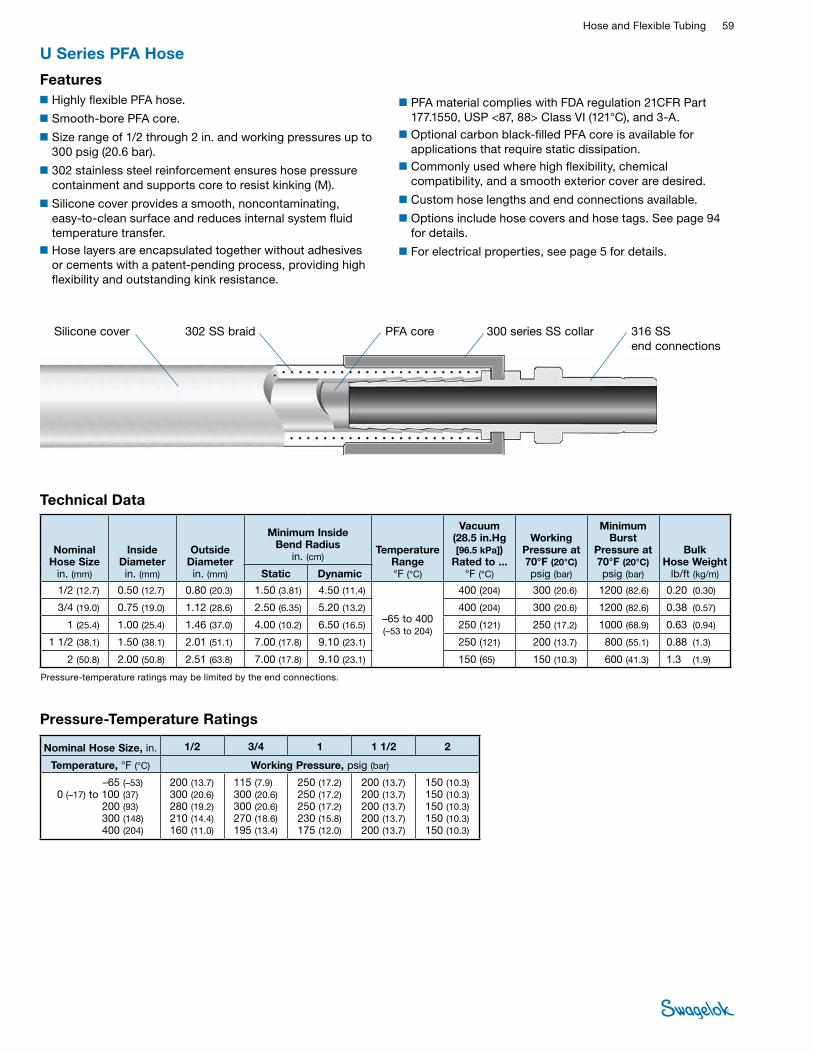
Hose and Flexible Tubing 59 HOSE /
FLEXIBLE TUBING
■PFA material complies with FDA regulation 21CFR Part 177.1550, USP <87, 88> Class VI (121°C), and 3-A.
■Optional carbon black-filled PFA core is available for applications that require static dissipation.
■Commonly used where high flexibility, chemical compatibility, and a smooth exterior cover are desired.
■Custom hose lengths and end connections available.
■Options include hose covers and hose tags. See page 94 for details.
■For electrical properties, see page 5 for details.
U Series PFA Hose
■Highly flexible PFA hose.
■Smooth-bore PFA core.
■Size range of 1/2 through 2 in. and working pressures up to 300 psig (20.6 bar).
■302 stainless steel reinforcement ensures hose pressure containment and supports core to resist kinking (M).
■Silicone cover provides a smooth, noncontaminating, easy-to-clean surface and reduces internal system fluid temperature transfer.
■Hose layers are encapsulated together without adhesives or cements with a patent-pending process, providing high flexibility and outstanding kink resistance.
Features
Technical Data
Nominal Hose Size
in. (mm)
Inside Diameter in. (mm)
Outside Diameter in. (mm)
Minimum Inside Bend Radius
in. (cm) Temperature
Range °F (°C)
Vacuum (28.5 in.Hg [96.5 kPa])
Rated to ...°F (°C)
Working Pressure at 70°F (20°C) psig (bar)
Minimum Burst
Pressure at70°F (20°C) psig (bar)
Bulk Hose Weight
lb/ft (kg/m)Static Dynamic
1/2 (12.7) 0.50 (12.7) 0.80 (20.3) 1.50 (3.81) 4.50 (11.4)
–65 to 400 (–53 to 204)
400 (204) 300 (20.6) 1200 (82.6) 0.20 (0.30)
3/4 (19.0) 0.75 (19.0) 1.12 (28.6) 2.50 (6.35) 5.20 (13.2) 400 (204) 300 (20.6) 1200 (82.6) 0.38 (0.57)
1 (25.4) 1.00 (25.4) 1.46 (37.0) 4.00 (10.2) 6.50 (16.5) 250 (121) 250 (17.2) 1000 (68.9) 0.63 (0.94)
1 1/2 (38.1) 1.50 (38.1) 2.01 (51.1) 7.00 (17.8) 9.10 (23.1) 250 (121) 200 (13.7) 800 (55.1) 0.88 (1.3)
2 (50.8) 2.00 (50.8) 2.51 (63.8) 7.00 (17.8) 9.10 (23.1) 150 (65) 150 (10.3) 600 (41.3) 1.3 (1.9)
Pressure-temperature ratings may be limited by the end connections.
PFA coreSilicone cover 302 SS braid 316 SS end connections
Pressure-Temperature Ratings
Nominal Hose Size, in. 1/2 3/4 1 1 1/2 2
Temperature, °F (°C) Working Pressure, psig (bar)
–65 (–53) 0 (–17) to 100 (37)
200 (93) 300 (148) 400 (204)
200 (13.7) 300 (20.6)280 (19.2) 210 (14.4) 160 (11.0)
115 (7.9) 300 (20.6) 300 (20.6)270 (18.6)195 (13.4)
250 (17.2) 250 (17.2)250 (17.2) 230 (15.8)175 (12.0)
200 (13.7) 200 (13.7) 200 (13.7) 200 (13.7) 200 (13.7)
150 (10.3)150 (10.3)150 (10.3)150 (10.3)150 (10.3)
300 series SS collar
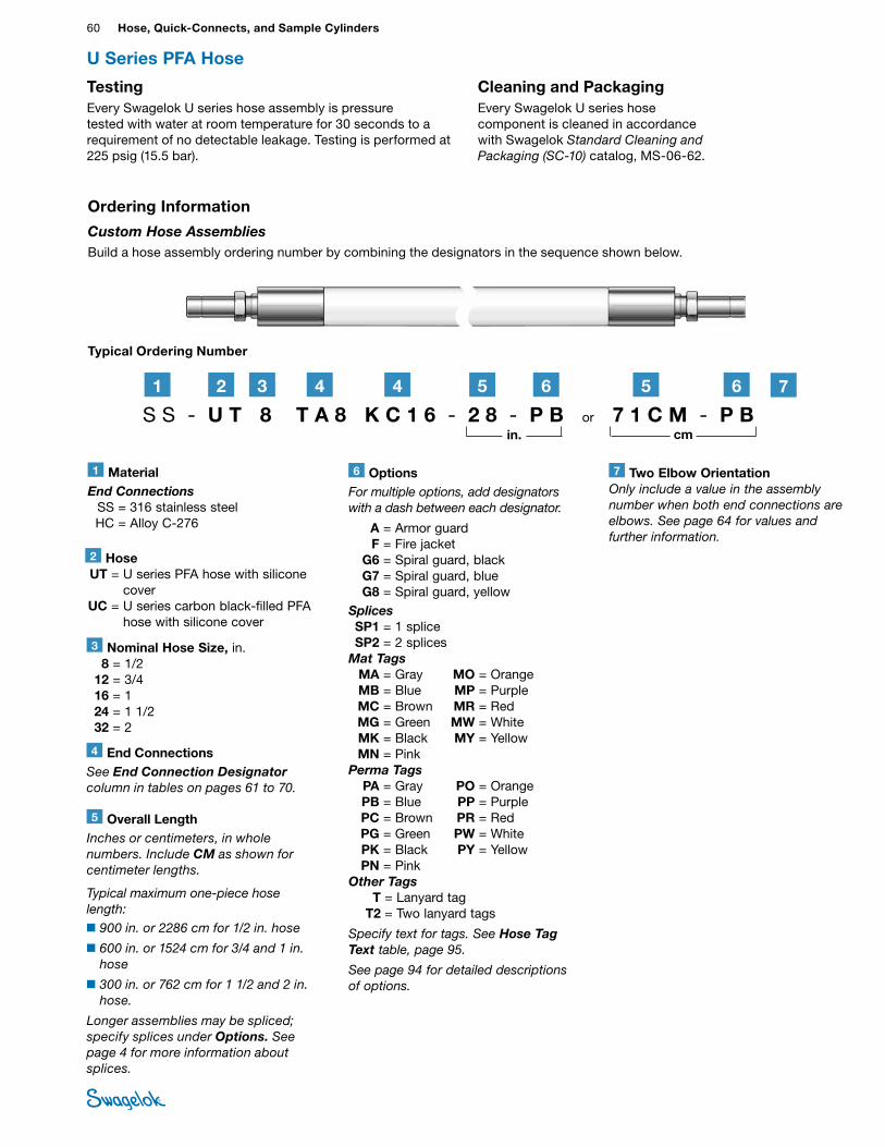
60 Hose, Quick-Connects, and Sample CylindersHO
SE /
FLEX
IBLE
TU
BING
U Series PFA Hose
Typical Ordering Number
S S - U T 8 T A 8 K C 1 6 - 2 8 - P B or 7 1 C M - P B 21 3 4 4 5 6 5 6
4 End ConnectionsSee End Connection Designator column in tables on pages 61 to 70.
5 Overall LengthInches or centimeters, in whole numbers. Include CM as shown for centimeter lengths.
Typical maximum one‑piece hose length:■900 in. or 2286 cm for 1/2 in. hose
■600 in. or 1524 cm for 3/4 and 1 in. hose
■300 in. or 762 cm for 1 1/2 and 2 in. hose.
Longer assemblies may be spliced; specify splices under Options. See page 4 for more information about splices.
2 Hose UT = U series PFA hose with silicone
cover UC = U series carbon black-filled PFA
hose with silicone cover
6 OptionsFor multiple options, add designators with a dash between each designator.
A = Armor guard F = Fire jacket G6 = Spiral guard, black G7 = Spiral guard, blue G8 = Spiral guard, yellowSplices SP1 = 1 splice SP2 = 2 splicesMat Tags MA = Gray MO = Orange MB = Blue MP = Purple MC = Brown MR = Red MG = Green MW = White MK = Black MY = Yellow MN = PinkPerma Tags PA = Gray PO = Orange PB = Blue PP = Purple PC = Brown PR = Red PG = Green PW = White PK = Black PY = Yellow PN = PinkOther Tags T = Lanyard tag T2 = Two lanyard tags
Specify text for tags. See Hose Tag Text table, page 95.
See page 94 for detailed descriptions of options.
1 MaterialEnd Connections SS = 316 stainless steel HC = Alloy C-276
3 Nominal Hose Size, in. 8 = 1/2 12 = 3/4 16 = 1 24 = 1 1/2 32 = 2
Ordering Information
Custom Hose AssembliesBuild a hose assembly ordering number by combining the designators in the sequence shown below.
in. cm
Testing Every Swagelok U series hose assembly is pressure tested with water at room temperature for 30 seconds to a requirement of no detectable leakage. Testing is performed at 225 psig (15.5 bar).
Cleaning and Packaging Every Swagelok U series hose component is cleaned in accordance with Swagelok Standard Cleaning and Packaging (SC‑10) catalog, MS-06-62.
7 Two Elbow OrientationOnly include a value in the assembly number when both end connections are elbows. See page 64 for values and further information.
7
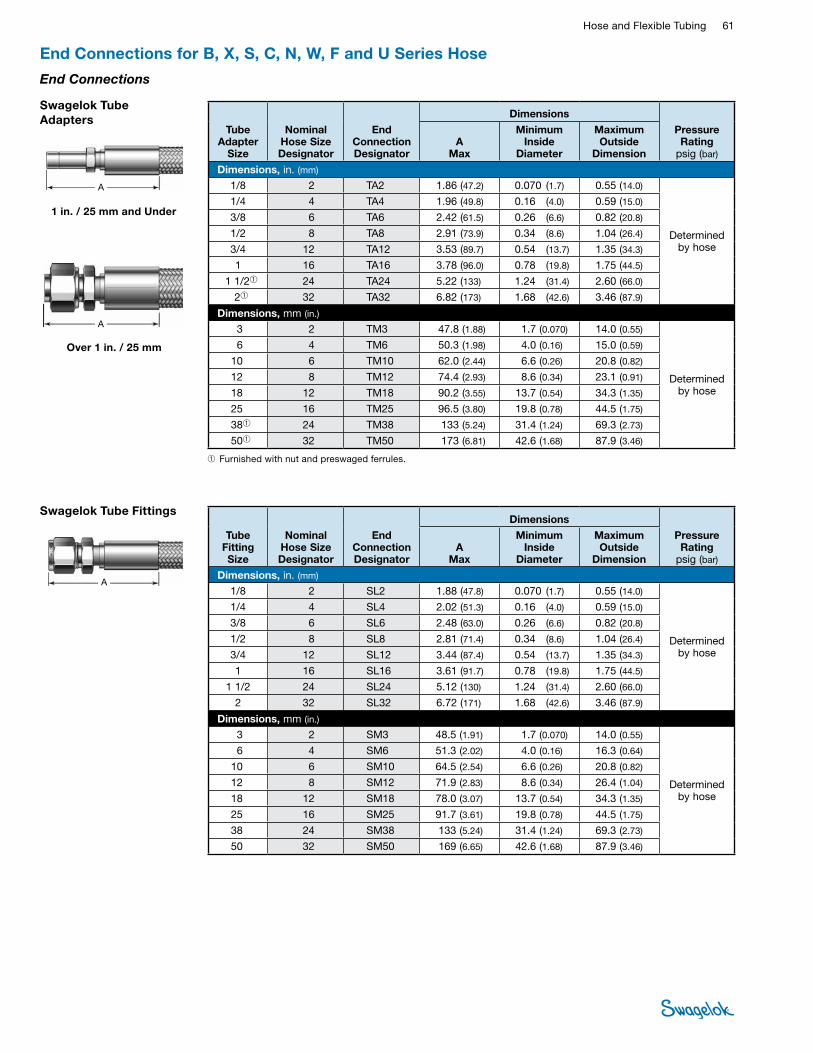
Hose and Flexible Tubing 61 HOSE /
FLEXIBLE TUBING
End Connections for B, X, S, C, N, W, F and U Series Hose
Swagelok Tube Fittings
A
Tube Fitting Size
Nominal Hose Size Designator
End Connection Designator
Dimensions
Pressure Rating
psig (bar)A
Max
Minimum Inside
Diameter
Maximum Outside
Dimension
Dimensions, in. (mm) 1/8 2 SL2 1.88 (47.8) 0.070 (1.7) 0.55 (14.0)
Determined by hose
1/4 4 SL4 2.02 (51.3) 0.16 (4.0) 0.59 (15.0)
3/8 6 SL6 2.48 (63.0) 0.26 (6.6) 0.82 (20.8)
1/2 8 SL8 2.81 (71.4) 0.34 (8.6) 1.04 (26.4)
3/4 12 SL12 3.44 (87.4) 0.54 (13.7) 1.35 (34.3)
1 16 SL16 3.61 (91.7) 0.78 (19.8) 1.75 (44.5)
1 1/2 24 SL24 5.12 (130) 1.24 (31.4) 2.60 (66.0)
2 32 SL32 6.72 (171) 1.68 (42.6) 3.46 (87.9)
Dimensions, mm (in.) 3 2 SM3 48.5 (1.91) 1.7 (0.070) 14.0 (0.55)
Determined by hose
6 4 SM6 51.3 (2.02) 4.0 (0.16) 16.3 (0.64)
10 6 SM10 64.5 (2.54) 6.6 (0.26) 20.8 (0.82)
12 8 SM12 71.9 (2.83) 8.6 (0.34) 26.4 (1.04)
18 12 SM18 78.0 (3.07) 13.7 (0.54) 34.3 (1.35)
25 16 SM25 91.7 (3.61) 19.8 (0.78) 44.5 (1.75)
38 24 SM38 133 (5.24) 31.4 (1.24) 69.3 (2.73)
50 32 SM50 169 (6.65) 42.6 (1.68) 87.9 (3.46)
End Connections
➀Furnished with nut and preswaged ferrules.
Swagelok Tube Adapters
A
A
Tube Adapter
Size
Nominal Hose Size Designator
End Connection Designator
Dimensions
Pressure Rating
psig (bar)A
Max
Minimum Inside
Diameter
Maximum Outside
Dimension
Dimensions, in. (mm) 1/8 2 TA2 1.86 (47.2) 0.070 (1.7) 0.55 (14.0)
Determined by hose
1/4 4 TA4 1.96 (49.8) 0.16 (4.0) 0.59 (15.0)
3/8 6 TA6 2.42 (61.5) 0.26 (6.6) 0.82 (20.8)
1/2 8 TA8 2.91 (73.9) 0.34 (8.6) 1.04 (26.4)
3/4 12 TA12 3.53 (89.7) 0.54 (13.7) 1.35 (34.3)
1 16 TA16 3.78 (96.0) 0.78 (19.8) 1.75 (44.5)
1 1/2➀ 24 TA24 5.22 (133) 1.24 (31.4) 2.60 (66.0)
2➀ 32 TA32 6.82 (173) 1.68 (42.6) 3.46 (87.9)
Dimensions, mm (in.) 3 2 TM3 47.8 (1.88) 1.7 (0.070) 14.0 (0.55)
Determined by hose
6 4 TM6 50.3 (1.98) 4.0 (0.16) 15.0 (0.59)
10 6 TM10 62.0 (2.44) 6.6 (0.26) 20.8 (0.82)
12 8 TM12 74.4 (2.93) 8.6 (0.34) 23.1 (0.91)
18 12 TM18 90.2 (3.55) 13.7 (0.54) 34.3 (1.35)
25 16 TM25 96.5 (3.80) 19.8 (0.78) 44.5 (1.75)
38➀ 24 TM38 133 (5.24) 31.4 (1.24) 69.3 (2.73)
50➀ 32 TM50 173 (6.81) 42.6 (1.68) 87.9 (3.46)
1 in. / 25 mm and Under
Over 1 in. / 25 mm
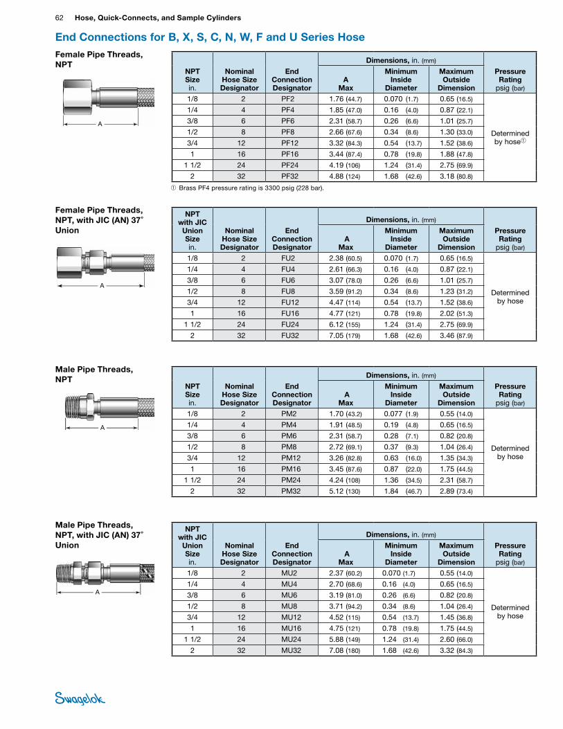
62 Hose, Quick-Connects, and Sample CylindersHO
SE /
FLEX
IBLE
TU
BING
Female Pipe Threads, NPT, with JIC (AN) 37˚ Union
A
NPT with JIC
Union Size in.
Nominal Hose Size Designator
End Connection Designator
Dimensions, in. (mm)
Pressure Rating
psig (bar) A
Max
Minimum Inside
Diameter
Maximum Outside
Dimension1/8 2 FU2 2.38 (60.5) 0.070 (1.7) 0.65 (16.5)
Determined by hose
1/4 4 FU4 2.61 (66.3) 0.16 (4.0) 0.87 (22.1)
3/8 6 FU6 3.07 (78.0) 0.26 (6.6) 1.01 (25.7)
1/2 8 FU8 3.59 (91.2) 0.34 (8.6) 1.23 (31.2)
3/4 12 FU12 4.47 (114) 0.54 (13.7) 1.52 (38.6)
1 16 FU16 4.77 (121) 0.78 (19.8) 2.02 (51.3)
1 1/2 24 FU24 6.12 (155) 1.24 (31.4) 2.75 (69.9)
2 32 FU32 7.05 (179) 1.68 (42.6) 3.46 (87.9)
Male Pipe Threads, NPT, with JIC (AN) 37˚ Union
A
NPT with JIC
Union Size in.
Nominal Hose Size Designator
End Connection Designator
Dimensions, in. (mm)
Pressure Rating
psig (bar) A
Max
Minimum Inside
Diameter
Maximum Outside
Dimension1/8 2 MU2 2.37 (60.2) 0.070 (1.7) 0.55 (14.0)
Determined by hose
1/4 4 MU4 2.70 (68.6) 0.16 (4.0) 0.65 (16.5)
3/8 6 MU6 3.19 (81.0) 0.26 (6.6) 0.82 (20.8)
1/2 8 MU8 3.71 (94.2) 0.34 (8.6) 1.04 (26.4)
3/4 12 MU12 4.52 (115) 0.54 (13.7) 1.45 (36.8)
1 16 MU16 4.75 (121) 0.78 (19.8) 1.75 (44.5)
1 1/2 24 MU24 5.88 (149) 1.24 (31.4) 2.60 (66.0)
2 32 MU32 7.08 (180) 1.68 (42.6) 3.32 (84.3)
End Connections for B, X, S, C, N, W, F and U Series Hose
Male Pipe Threads, NPT
NPT Size in.
Nominal Hose Size Designator
End Connection Designator
Dimensions, in. (mm)
Pressure Rating
psig (bar) A
Max
Minimum Inside
Diameter
Maximum Outside
Dimension1/8 2 PM2 1.70 (43.2) 0.077 (1.9) 0.55 (14.0)
Determined by hose
1/4 4 PM4 1.91 (48.5) 0.19 (4.8) 0.65 (16.5)
3/8 6 PM6 2.31 (58.7) 0.28 (7.1) 0.82 (20.8)
1/2 8 PM8 2.72 (69.1) 0.37 (9.3) 1.04 (26.4)
3/4 12 PM12 3.26 (82.8) 0.63 (16.0) 1.35 (34.3)
1 16 PM16 3.45 (87.6) 0.87 (22.0) 1.75 (44.5)
1 1/2 24 PM24 4.24 (108) 1.36 (34.5) 2.31 (58.7)
2 32 PM32 5.12 (130) 1.84 (46.7) 2.89 (73.4)
A
Female Pipe Threads, NPT
NPT Size in.
Nominal Hose Size Designator
End Connection Designator
Dimensions, in. (mm)
Pressure Rating
psig (bar)A
Max
Minimum Inside
Diameter
Maximum Outside
Dimension1/8 2 PF2 1.76 (44.7) 0.070 (1.7) 0.65 (16.5)
Determined by hose➀
1/4 4 PF4 1.85 (47.0) 0.16 (4.0) 0.87 (22.1)
3/8 6 PF6 2.31 (58.7) 0.26 (6.6) 1.01 (25.7)
1/2 8 PF8 2.66 (67.6) 0.34 (8.6) 1.30 (33.0)
3/4 12 PF12 3.32 (84.3) 0.54 (13.7) 1.52 (38.6)
1 16 PF16 3.44 (87.4) 0.78 (19.8) 1.88 (47.8)
1 1/2 24 PF24 4.19 (106) 1.24 (31.4) 2.75 (69.9)
2 32 PF32 4.88 (124) 1.68 (42.6) 3.18 (80.8)
A
➀Brass PF4 pressure rating is 3300 psig (228 bar).
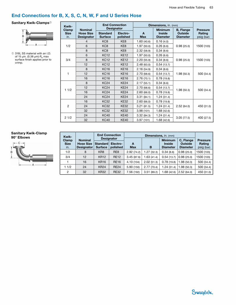
Hose and Flexible Tubing 63 HOSE /
FLEXIBLE TUBING
End Connections for B, X, S, C, N, W, F and U Series HoseSanitary Kwik-Clamps➀
Kwik- Clamp Size in.
Nominal Hose Size Designator
End Connection Designator
Dimensions, in. (mm)
Pressure Rating
psig (bar) A
Max
Minimum Inside
Diameter
B, Flange Outside
DiameterStandard Surface
Electro-polished
1/2
4 KC8 KE8 1.60 (40.6) 0.16 (4.0)
0.98 (25.0) 1500 (103)6 KC8 KE8 1.97 (50.0) 0.26 (6.6)
8 KC8 KE8 2.32 (58.9) 0.34 (8.6)
3/4
6 KC12 KE12 1.97 (50.0) 0.26 (6.6)
0.98 (25.0) 1500 (103)8 KC12 KE12 2.20 (55.9) 0.34 (8.6)
12 KC12 KE12 2.48 (63.0) 0.54 (13.7)
1
8 KC16 KE16 2.16 (54.9) 0.34 (8.6)
1.98 (50.3) 500 (34.4)12 KC16 KE16 2.70 (68.6) 0.54 (13.7)
16 KC16 KE16 2.76 (70.1) 0.78 (19.8)
1 1/2
8 KC24 KE24 2.17 (55.1) 0.34 (8.6)
1.98 (50.3) 500 (34.4)12 KC24 KE24 2.70 (68.6) 0.54 (13.7)
16 KC24 KE24 2.60 (66.0) 0.78 (19.8)
24 KC24 KE24 3.31 (84.1) 1.24 (31.4)
2
16 KC32 KE32 2.60 (66.0) 0.78 (19.8)
2.52 (64.0) 450 (31.0)24 KC32 KE32 3.21 (81.5) 1.24 (31.4)
32 KC32 KE32 3.98 (101) 1.68 (42.6)
2 1/224 KC40 KE40 3.32 (84.3) 1.24 (31.4)
3.05 (77.5) 400 (27.5)32 KC40 KE40 3.97 (101) 1.68 (42.6)
➀ 316L SS material with an I.D. of 15 µin. (0.38 µm) Ra max surface finish applies prior to crimp.
A
B
Sanitary Kwik-Clamp 90° Elbows Kwik-
Clamp Size in.
Nominal Hose Size Designator
End Connection Designator
Dimensions, in. (mm)
Pressure Rating
psig (bar)A
Max B
Minimum Inside
Diameter
C, Flange Outside
DiameterStandard Surface
Electro-polished
1/2 8 KR8 RE8 2.92 (74.2) 1.27 (32.3) 0.34 (8.6) 0.98 (25.0) 1500 (103)
3/4 12 KR12 RE12 3.45 (87.6) 1.63 (41.4) 0.54 (13.7) 0.98 (25.0) 1500 (103)
1 16 KR16 RE16 4.10 (104) 2.02 (51.3) 0.78 (19.8) 1.98 (50.3) 500 (34.4)
1 1/2 24 KR24 RE24 5.90 (150) 2.77 (70.4) 1.24 (31.4) 1.98 (50.3) 500 (34.4)
2 32 KR32 RE32 7.56 (192) 3.51 (89.2) 1.68 (42.6) 2.52 (64.0) 450 (31.0)
A
B
C
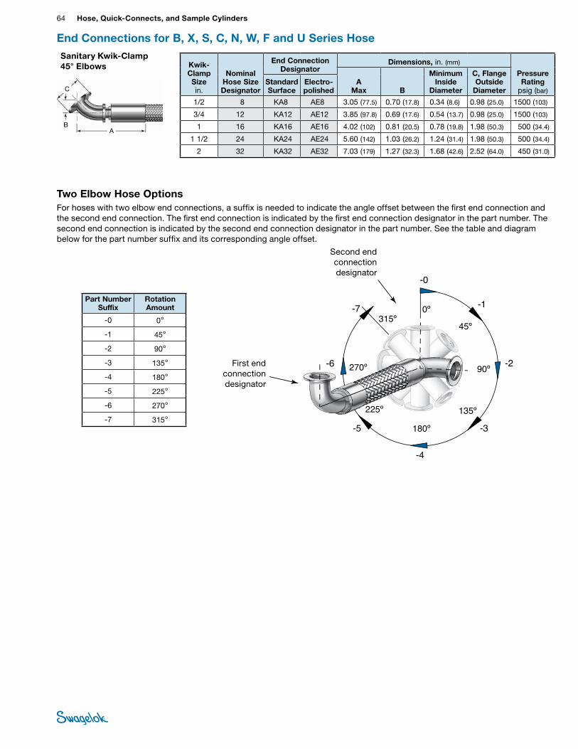
64 Hose, Quick-Connects, and Sample CylindersHO
SE /
FLEX
IBLE
TU
BING
Part Number Suffix
Rotation Amount
-0 0°
-1 45°
-2 90°
-3 135°
-4 180°
-5 225°
-6 270°
-7 315°
Two Elbow Hose OptionsFor hoses with two elbow end connections, a suffix is needed to indicate the angle offset between the first end connection and the second end connection. The first end connection is indicated by the first end connection designator in the part number. The second end connection is indicated by the second end connection designator in the part number. See the table and diagram below for the part number suffix and its corresponding angle offset.
-1
-2
-3
-4
-5
-6
-7 0º
45º
90º
135º
180º
225º
270º
315º
elbow end connection 2a
-0
Kwik- Clamp Size in.
Nominal Hose Size Designator
End Connection Designator
Dimensions, in. (mm)
Pressure Rating
psig (bar)A
Max B
Minimum Inside
Diameter
C, Flange Outside
DiameterStandard Surface
Electro-polished
1/2 8 KA8 AE8 3.05 (77.5) 0.70 (17.8) 0.34 (8.6) 0.98 (25.0) 1500 (103)
3/4 12 KA12 AE12 3.85 (97.8) 0.69 (17.6) 0.54 (13.7) 0.98 (25.0) 1500 (103)
1 16 KA16 AE16 4.02 (102) 0.81 (20.5) 0.78 (19.8) 1.98 (50.3) 500 (34.4)
1 1/2 24 KA24 AE24 5.60 (142) 1.03 (26.2) 1.24 (31.4) 1.98 (50.3) 500 (34.4)
2 32 KA32 AE32 7.03 (179) 1.27 (32.3) 1.68 (42.6) 2.52 (64.0) 450 (31.0)
Sanitary Kwik-Clamp 45° Elbows
A B
C
End Connections for B, X, S, C, N, W, F and U Series Hose
First end connection designator
Second end connection designator
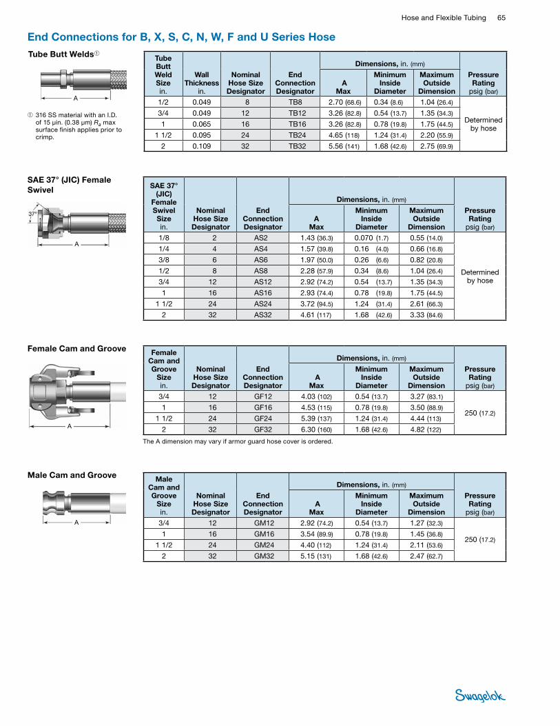
Hose and Flexible Tubing 65 HOSE /
FLEXIBLE TUBING
SAE 37° (JIC) Female Swivel
A
SAE 37° (JIC)
Female Swivel Size in.
Nominal Hose Size Designator
End Connection Designator
Dimensions, in. (mm)
Pressure Rating
psig (bar)A
Max
Minimum Inside
Diameter
Maximum Outside
Dimension1/8 2 AS2 1.43 (36.3) 0.070 (1.7) 0.55 (14.0)
Determined by hose
1/4 4 AS4 1.57 (39.8) 0.16 (4.0) 0.66 (16.8)
3/8 6 AS6 1.97 (50.0) 0.26 (6.6) 0.82 (20.8)
1/2 8 AS8 2.28 (57.9) 0.34 (8.6) 1.04 (26.4)
3/4 12 AS12 2.92 (74.2) 0.54 (13.7) 1.35 (34.3)
1 16 AS16 2.93 (74.4) 0.78 (19.8) 1.75 (44.5)
1 1/2 24 AS24 3.72 (94.5) 1.24 (31.4) 2.61 (66.3)
2 32 AS32 4.61 (117) 1.68 (42.6) 3.33 (84.6)
End Connections for B, X, S, C, N, W, F and U Series Hose
A
Tube Butt Welds➀ Tube Butt Weld Size in.
Wall Thickness
in.
Nominal Hose Size Designator
End Connection Designator
Dimensions, in. (mm)
Pressure Rating
psig (bar) A
Max
Minimum Inside
Diameter
Maximum Outside
Dimension1/2 0.049 8 TB8 2.70 (68.6) 0.34 (8.6) 1.04 (26.4)
Determined by hose
3/4 0.049 12 TB12 3.26 (82.8) 0.54 (13.7) 1.35 (34.3)
1 0.065 16 TB16 3.26 (82.8) 0.78 (19.8) 1.75 (44.5)
1 1/2 0.095 24 TB24 4.65 (118) 1.24 (31.4) 2.20 (55.9)
2 0.109 32 TB32 5.56 (141) 1.68 (42.6) 2.75 (69.9)
➀ 316 SS material with an I.D. of 15 µin. (0.38 µm) Ra max surface finish applies prior to crimp.
A
Female Cam and Groove Female Cam and Groove
Size in.
Nominal Hose Size Designator
End Connection Designator
Dimensions, in. (mm)
Pressure Rating
psig (bar) A
Max
Minimum Inside
Diameter
Maximum Outside
Dimension3/4 12 GF12 4.03 (102) 0.54 (13.7) 3.27 (83.1)
250 (17.2)1 16 GF16 4.53 (115) 0.78 (19.8) 3.50 (88.9)
1 1/2 24 GF24 5.39 (137) 1.24 (31.4) 4.44 (113)
2 32 GF32 6.30 (160) 1.68 (42.6) 4.82 (122)
The A dimension may vary if armor guard hose cover is ordered.
Male Cam and Groove Male Cam and Groove
Size in.
Nominal Hose Size Designator
End Connection Designator
Dimensions, in. (mm)
Pressure Rating
psig (bar) A
Max
Minimum Inside
Diameter
Maximum Outside
Dimension3/4 12 GM12 2.92 (74.2) 0.54 (13.7) 1.27 (32.3)
250 (17.2)1 16 GM16 3.54 (89.9) 0.78 (19.8) 1.45 (36.8)
1 1/2 24 GM24 4.40 (112) 1.24 (31.4) 2.11 (53.6)
2 32 GM32 5.15 (131) 1.68 (42.6) 2.47 (62.7)
A
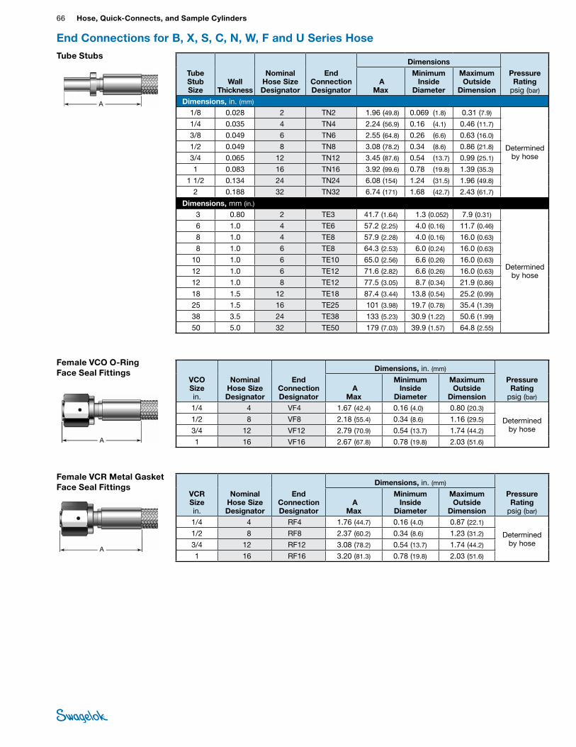
66 Hose, Quick-Connects, and Sample CylindersHO
SE /
FLEX
IBLE
TU
BING
End Connections for B, X, S, C, N, W, F and U Series Hose
Female VCO O-Ring Face Seal Fittings
A
VCO Size in.
Nominal Hose Size Designator
End Connection Designator
Dimensions, in. (mm)
Pressure Rating
psig (bar) A
Max
Minimum Inside
Diameter
Maximum Outside
Dimension1/4 4 VF4 1.67 (42.4) 0.16 (4.0) 0.80 (20.3)
Determined by hose
1/2 8 VF8 2.18 (55.4) 0.34 (8.6) 1.16 (29.5)
3/4 12 VF12 2.79 (70.9) 0.54 (13.7) 1.74 (44.2)
1 16 VF16 2.67 (67.8) 0.78 (19.8) 2.03 (51.6)
Tube Stubs
Tube Stub Size
Wall Thickness
Nominal Hose Size Designator
End Connection Designator
Dimensions
Pressure Rating
psig (bar) A
Max
Minimum Inside
Diameter
Maximum Outside
Dimension
Dimensions, in. (mm) 1/8 0.028 2 TN2 1.96 (49.8) 0.069 (1.8) 0.31 (7.9)
Determined by hose
1/4 0.035 4 TN4 2.24 (56.9) 0.16 (4.1) 0.46 (11.7)
3/8 0.049 6 TN6 2.55 (64.8) 0.26 (6.6) 0.63 (16.0)
1/2 0.049 8 TN8 3.08 (78.2) 0.34 (8.6) 0.86 (21.8)
3/4 0.065 12 TN12 3.45 (87.6) 0.54 (13.7) 0.99 (25.1)
1 0.083 16 TN16 3.92 (99.6) 0.78 (19.8) 1.39 (35.3)
1 1/2 0.134 24 TN24 6.08 (154) 1.24 (31.5) 1.96 (49.8)
2 0.188 32 TN32 6.74 (171) 1.68 (42.7) 2.43 (61.7)
Dimensions, mm (in.) 3 0.80 2 TE3 41.7 (1.64) 1.3 (0.052) 7.9 (0.31)
Determined by hose
6 1.0 4 TE6 57.2 (2.25) 4.0 (0.16) 11.7 (0.46)
8 1.0 4 TE8 57.9 (2.28) 4.0 (0.16) 16.0 (0.63)
8 1.0 6 TE8 64.3 (2.53) 6.0 (0.24) 16.0 (0.63)
10 1.0 6 TE10 65.0 (2.56) 6.6 (0.26) 16.0 (0.63)
12 1.0 6 TE12 71.6 (2.82) 6.6 (0.26) 16.0 (0.63)
12 1.0 8 TE12 77.5 (3.05) 8.7 (0.34) 21.9 (0.86)
18 1.5 12 TE18 87.4 (3.44) 13.8 (0.54) 25.2 (0.99)
25 1.5 16 TE25 101 (3.98) 19.7 (0.78) 35.4 (1.39)
38 3.5 24 TE38 133 (5.23) 30.9 (1.22) 50.6 (1.99)
50 5.0 32 TE50 179 (7.03) 39.9 (1.57) 64.8 (2.55)
A
Female VCR Metal Gasket Face Seal Fittings
A
VCR Size in.
Nominal Hose Size Designator
End Connection Designator
Dimensions, in. (mm)
Pressure Rating
psig (bar) A
Max
Minimum Inside
Diameter
Maximum Outside
Dimension1/4 4 RF4 1.76 (44.7) 0.16 (4.0) 0.87 (22.1)
Determined by hose
1/2 8 RF8 2.37 (60.2) 0.34 (8.6) 1.23 (31.2)
3/4 12 RF12 3.08 (78.2) 0.54 (13.7) 1.74 (44.2)
1 16 RF16 3.20 (81.3) 0.78 (19.8) 2.03 (51.6)
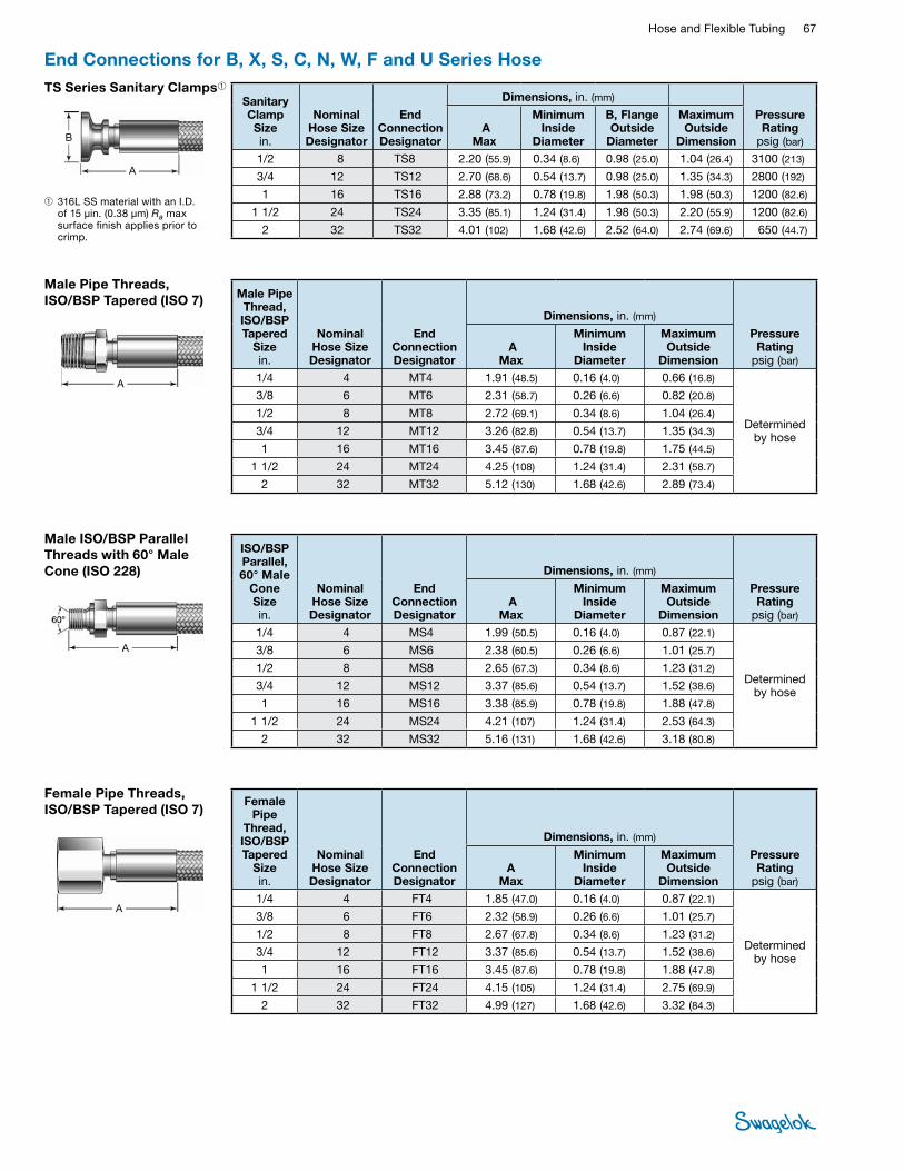
Hose and Flexible Tubing 67 HOSE /
FLEXIBLE TUBING
A
Male ISO/BSP Parallel Threads with 60° Male Cone (ISO 228)
ISO/BSP Parallel, 60° Male
Cone Size in.
Nominal Hose Size Designator
End Connection Designator
Dimensions, in. (mm)
Pressure Rating
psig (bar) A
Max
Minimum Inside
Diameter
Maximum Outside
Dimension1/4 4 MS4 1.99 (50.5) 0.16 (4.0) 0.87 (22.1)
Determined by hose
3/8 6 MS6 2.38 (60.5) 0.26 (6.6) 1.01 (25.7)
1/2 8 MS8 2.65 (67.3) 0.34 (8.6) 1.23 (31.2)
3/4 12 MS12 3.37 (85.6) 0.54 (13.7) 1.52 (38.6)
1 16 MS16 3.38 (85.9) 0.78 (19.8) 1.88 (47.8)
1 1/2 24 MS24 4.21 (107) 1.24 (31.4) 2.53 (64.3)
2 32 MS32 5.16 (131) 1.68 (42.6) 3.18 (80.8)
End Connections for B, X, S, C, N, W, F and U Series Hose
Male Pipe Threads, ISO/BSP Tapered (ISO 7) Male Pipe
Thread, ISO/BSP Tapered
Size in.
Nominal Hose Size Designator
End Connection Designator
Dimensions, in. (mm)
Pressure Rating
psig (bar) A
Max
Minimum Inside
Diameter
Maximum Outside
Dimension1/4 4 MT4 1.91 (48.5) 0.16 (4.0) 0.66 (16.8)
Determined by hose
3/8 6 MT6 2.31 (58.7) 0.26 (6.6) 0.82 (20.8)
1/2 8 MT8 2.72 (69.1) 0.34 (8.6) 1.04 (26.4)
3/4 12 MT12 3.26 (82.8) 0.54 (13.7) 1.35 (34.3)
1 16 MT16 3.45 (87.6) 0.78 (19.8) 1.75 (44.5)
1 1/2 24 MT24 4.25 (108) 1.24 (31.4) 2.31 (58.7)
2 32 MT32 5.12 (130) 1.68 (42.6) 2.89 (73.4)
A
Female Pipe Threads, ISO/BSP Tapered (ISO 7)
Female Pipe
Thread, ISO/BSP Tapered
Size in.
Nominal Hose Size Designator
End Connection Designator
Dimensions, in. (mm)
Pressure Rating
psig (bar)A
Max
Minimum Inside
Diameter
Maximum Outside
Dimension1/4 4 FT4 1.85 (47.0) 0.16 (4.0) 0.87 (22.1)
Determined by hose
3/8 6 FT6 2.32 (58.9) 0.26 (6.6) 1.01 (25.7)
1/2 8 FT8 2.67 (67.8) 0.34 (8.6) 1.23 (31.2)
3/4 12 FT12 3.37 (85.6) 0.54 (13.7) 1.52 (38.6)
1 16 FT16 3.45 (87.6) 0.78 (19.8) 1.88 (47.8)
1 1/2 24 FT24 4.15 (105) 1.24 (31.4) 2.75 (69.9)
2 32 FT32 4.99 (127) 1.68 (42.6) 3.32 (84.3)
A
A
TS Series Sanitary Clamps➀Sanitary Clamp Size in.
Nominal Hose Size Designator
End Connection Designator
Dimensions, in. (mm)
Pressure Rating
psig (bar) A
Max
Minimum Inside
Diameter
B, Flange Outside
Diameter
Maximum Outside
Dimension1/2 8 TS8 2.20 (55.9) 0.34 (8.6) 0.98 (25.0) 1.04 (26.4) 3100 (213)
3/4 12 TS12 2.70 (68.6) 0.54 (13.7) 0.98 (25.0) 1.35 (34.3) 2800 (192)
1 16 TS16 2.88 (73.2) 0.78 (19.8) 1.98 (50.3) 1.98 (50.3) 1200 (82.6)
1 1/2 24 TS24 3.35 (85.1) 1.24 (31.4) 1.98 (50.3) 2.20 (55.9) 1200 (82.6)
2 32 TS32 4.01 (102) 1.68 (42.6) 2.52 (64.0) 2.74 (69.6) 650 (44.7)
➀ 316L SS material with an I.D. of 15 µin. (0.38 µm) Ra max surface finish applies prior to crimp.
B
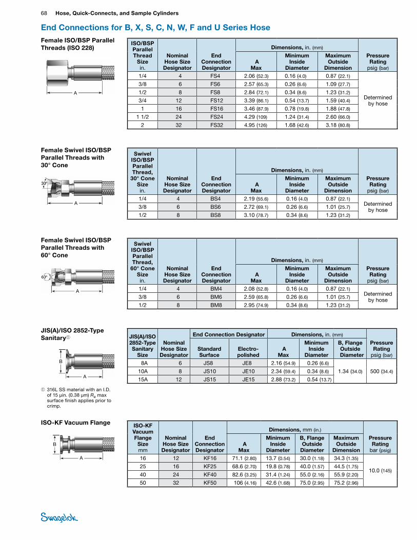
68 Hose, Quick-Connects, and Sample CylindersHO
SE /
FLEX
IBLE
TU
BING
End Connections for B, X, S, C, N, W, F and U Series HoseFemale ISO/BSP Parallel Threads (ISO 228)
ISO/BSP Parallel Thread
Size in.
Nominal Hose Size Designator
End Connection Designator
Dimensions, in. (mm)
Pressure Rating
psig (bar) A
Max
Minimum Inside
Diameter
Maximum Outside
Dimension1/4 4 FS4 2.06 (52.3) 0.16 (4.0) 0.87 (22.1)
Determined by hose
3/8 6 FS6 2.57 (65.3) 0.26 (6.6) 1.09 (27.7)
1/2 8 FS8 2.84 (72.1) 0.34 (8.6) 1.23 (31.2)
3/4 12 FS12 3.39 (86.1) 0.54 (13.7) 1.59 (40.4)
1 16 FS16 3.46 (87.9) 0.78 (19.8) 1.88 (47.8)
1 1/2 24 FS24 4.29 (109) 1.24 (31.4) 2.60 (66.0)
2 32 FS32 4.95 (126) 1.68 (42.6) 3.18 (80.8)
A
Female Swivel ISO/BSP Parallel Threads with 30° Cone
Swivel ISO/BSP Parallel Thread,
30° Cone Size in.
Nominal Hose Size Designator
End Connection Designator
Dimensions, in. (mm)
Pressure Rating
psig (bar) A
Max
Minimum Inside
Diameter
Maximum Outside
Dimension1/4 4 BS4 2.19 (55.6) 0.16 (4.0) 0.87 (22.1)
Determined by hose3/8 6 BS6 2.72 (69.1) 0.26 (6.6) 1.01 (25.7)
1/2 8 BS8 3.10 (78.7) 0.34 (8.6) 1.23 (31.2)
A
Female Swivel ISO/BSP Parallel Threads with 60° Cone
Swivel ISO/BSP Parallel Thread,
60° Cone Size in.
Nominal Hose Size Designator
End Connection Designator
Dimensions, in. (mm)
Pressure Rating
psig (bar) A
Max
Minimum Inside
Diameter
Maximum Outside
Dimension1/4 4 BM4 2.08 (52.8) 0.16 (4.0) 0.87 (22.1)
Determined by hose3/8 6 BM6 2.59 (65.8) 0.26 (6.6) 1.01 (25.7)
1/2 8 BM8 2.95 (74.9) 0.34 (8.6) 1.23 (31.2)
A
JIS(A)/ISO 2852-Type Sanitary➀ JIS(A)/ISO
2852-Type Sanitary
Size
Nominal Hose Size Designator
End Connection Designator Dimensions, in. (mm)
Pressure Rating
psig (bar)Standard Surface
Electro-polished
A Max
Minimum Inside
Diameter
B, Flange Outside
Diameter8A 6 JS8 JE8 2.16 (54.9) 0.26 (6.6)
1.34 (34.0) 500 (34.4)10A 8 JS10 JE10 2.34 (59.4) 0.34 (8.6)
15A 12 JS15 JE15 2.88 (73.2) 0.54 (13.7)A
➀ 316L SS material with an I.D. of 15 µin. (0.38 µm) Ra max surface finish applies prior to crimp.
B
A
ISO-KF Vacuum Flange ISO-KF Vacuum Flange
Size mm
Nominal Hose Size Designator
End Connection Designator
Dimensions, mm (in.)
Pressure Rating
bar (psig) A
Max
Minimum Inside
Diameter
B, Flange Outside
Diameter
Maximum Outside
Dimension16 12 KF16 71.1 (2.80) 13.7 (0.54) 30.0 (1.18) 34.3 (1.35)
10.0 (145)25 16 KF25 68.6 (2.70) 19.8 (0.78) 40.0 (1.57) 44.5 (1.75)
40 24 KF40 82.6 (3.25) 31.4 (1.24) 55.0 (2.16) 55.9 (2.20)
50 32 KF50 106 (4.16) 42.6 (1.68) 75.0 (2.95) 75.2 (2.96)
B
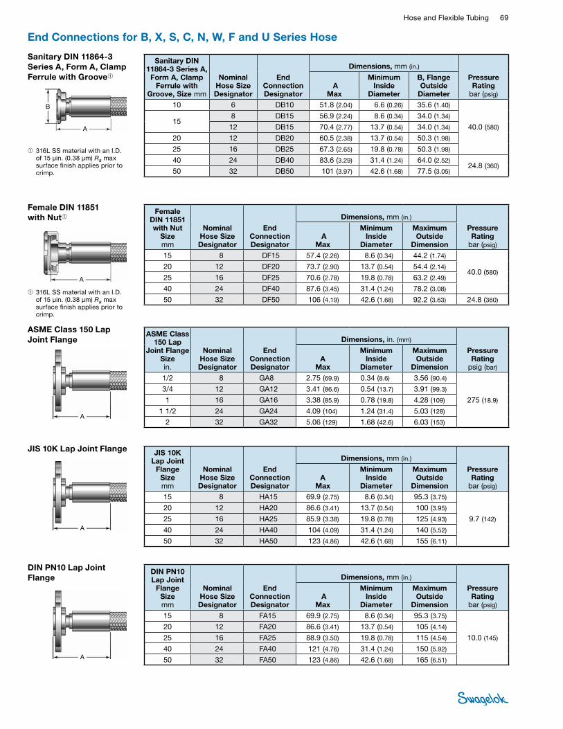
Hose and Flexible Tubing 69 HOSE /
FLEXIBLE TUBING
End Connections for B, X, S, C, N, W, F and U Series Hose
DIN PN10 Lap Joint Flange
DIN PN10 Lap Joint
Flange Size mm
Nominal Hose Size Designator
End Connection Designator
Dimensions, mm (in.)
Pressure Rating
bar (psig) A
Max
Minimum Inside
Diameter
Maximum Outside
Dimension15 8 FA15 69.9 (2.75) 8.6 (0.34) 95.3 (3.75)
10.0 (145)
20 12 FA20 86.6 (3.41) 13.7 (0.54) 105 (4.14)
25 16 FA25 88.9 (3.50) 19.8 (0.78) 115 (4.54)
40 24 FA40 121 (4.76) 31.4 (1.24) 150 (5.92)
50 32 FA50 123 (4.86) 42.6 (1.68) 165 (6.51)A
JIS 10K Lap Joint Flange JIS 10K Lap Joint
Flange Size mm
Nominal Hose Size Designator
End Connection Designator
Dimensions, mm (in.)
Pressure Rating
bar (psig)A
Max
Minimum Inside
Diameter
Maximum Outside
Dimension15 8 HA15 69.9 (2.75) 8.6 (0.34) 95.3 (3.75)
9.7 (142)
20 12 HA20 86.6 (3.41) 13.7 (0.54) 100 (3.95)
25 16 HA25 85.9 (3.38) 19.8 (0.78) 125 (4.93)
40 24 HA40 104 (4.09) 31.4 (1.24) 140 (5.52)
50 32 HA50 123 (4.86) 42.6 (1.68) 155 (6.11)
A
A
ASME Class 150 Lap Joint Flange
ASME Class 150 Lap
Joint Flange Size in.
Nominal Hose Size Designator
End Connection Designator
Dimensions, in. (mm)
Pressure Rating
psig (bar)A
Max
Minimum Inside
Diameter
Maximum Outside
Dimension1/2 8 GA8 2.75 (69.9) 0.34 (8.6) 3.56 (90.4)
275 (18.9)
3/4 12 GA12 3.41 (86.6) 0.54 (13.7) 3.91 (99.3)
1 16 GA16 3.38 (85.9) 0.78 (19.8) 4.28 (109)
1 1/2 24 GA24 4.09 (104) 1.24 (31.4) 5.03 (128)
2 32 GA32 5.06 (129) 1.68 (42.6) 6.03 (153)
A
Female DIN 11851 with Nut➀
Female DIN 11851 with Nut
Sizemm
Nominal Hose Size Designator
End Connection Designator
Dimensions, mm (in.)
Pressure Rating
bar (psig) A
Max
Minimum Inside
Diameter
Maximum Outside
Dimension15 8 DF15 57.4 (2.26) 8.6 (0.34) 44.2 (1.74)
40.0 (580)20 12 DF20 73.7 (2.90) 13.7 (0.54) 54.4 (2.14)
25 16 DF25 70.6 (2.78) 19.8 (0.78) 63.2 (2.49)
40 24 DF40 87.6 (3.45) 31.4 (1.24) 78.2 (3.08)
50 32 DF50 106 (4.19) 42.6 (1.68) 92.2 (3.63) 24.8 (360)➀ 316L SS material with an I.D.
of 15 µin. (0.38 µm) Ra max surface finish applies prior to crimp.
Sanitary DIN 11864-3 Series A, Form A, Clamp Ferrule with Groove➀
Sanitary DIN 11864-3 Series A,
Form A, Clamp Ferrule with
Groove, Size mm
Nominal Hose Size Designator
End Connection Designator
Dimensions, mm (in.)
Pressure Rating
bar (psig) A
Max
Minimum Inside
Diameter
B, Flange Outside
Diameter10 6 DB10 51.8 (2.04) 6.6 (0.26) 35.6 (1.40)
40.0 (580)15
8 DB15 56.9 (2.24) 8.6 (0.34) 34.0 (1.34)
12 DB15 70.4 (2.77) 13.7 (0.54) 34.0 (1.34)
20 12 DB20 60.5 (2.38) 13.7 (0.54) 50.3 (1.98)
25 16 DB25 67.3 (2.65) 19.8 (0.78) 50.3 (1.98)
40 24 DB40 83.6 (3.29) 31.4 (1.24) 64.0 (2.52)24.8 (360)
50 32 DB50 101 (3.97) 42.6 (1.68) 77.5 (3.05)
A
➀ 316L SS material with an I.D. of 15 µin. (0.38 µm) Ra max surface finish applies prior to crimp.
B
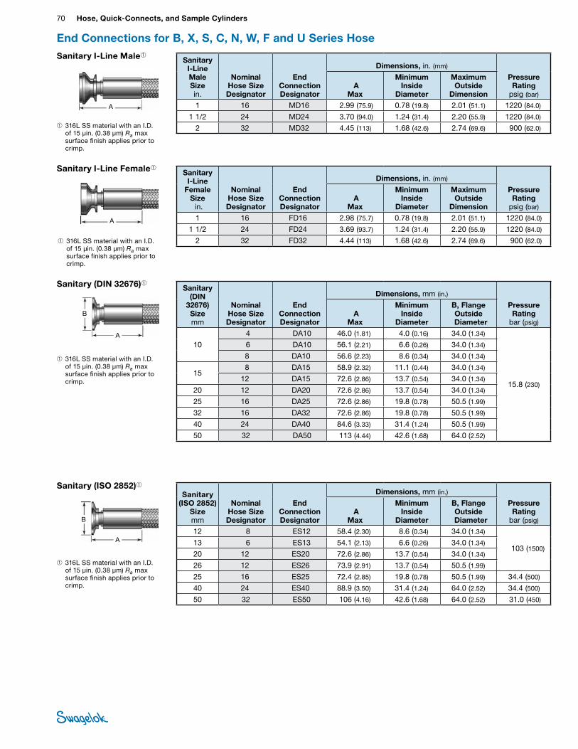
70 Hose, Quick-Connects, and Sample CylindersHO
SE /
FLEX
IBLE
TU
BING
End Connections for B, X, S, C, N, W, F and U Series Hose
Sanitary I-Line Female➀Sanitary
I-Line Female
Size in.
Nominal Hose Size Designator
End Connection Designator
Dimensions, in. (mm)
Pressure Rating
psig (bar) A
Max
Minimum Inside
Diameter
Maximum Outside
Dimension1 16 FD16 2.98 (75.7) 0.78 (19.8) 2.01 (51.1) 1220 (84.0)
1 1/2 24 FD24 3.69 (93.7) 1.24 (31.4) 2.20 (55.9) 1220 (84.0)
2 32 FD32 4.44 (113) 1.68 (42.6) 2.74 (69.6) 900 (62.0)
A
➀ 316L SS material with an I.D. of 15 µin. (0.38 µm) Ra max surface finish applies prior to crimp.
Sanitary (DIN 32676)➀ Sanitary (DIN
32676) Size mm
Nominal Hose Size Designator
End Connection Designator
Dimensions, mm (in.)
Pressure Rating
bar (psig) A
Max
Minimum Inside
Diameter
B, Flange Outside
Diameter
10
4 DA10 46.0 (1.81) 4.0 (0.16) 34.0 (1.34)
15.8 (230)
6 DA10 56.1 (2.21) 6.6 (0.26) 34.0 (1.34)
8 DA10 56.6 (2.23) 8.6 (0.34) 34.0 (1.34)
158 DA15 58.9 (2.32) 11.1 (0.44) 34.0 (1.34)
12 DA15 72.6 (2.86) 13.7 (0.54) 34.0 (1.34)
20 12 DA20 72.6 (2.86) 13.7 (0.54) 34.0 (1.34)
25 16 DA25 72.6 (2.86) 19.8 (0.78) 50.5 (1.99)
32 16 DA32 72.6 (2.86) 19.8 (0.78) 50.5 (1.99)
40 24 DA40 84.6 (3.33) 31.4 (1.24) 50.5 (1.99)
50 32 DA50 113 (4.44) 42.6 (1.68) 64.0 (2.52)
A
➀ 316L SS material with an I.D. of 15 µin. (0.38 µm) Ra max surface finish applies prior to crimp.
B
A
Sanitary (ISO 2852)➀Sanitary
(ISO 2852) Size mm
Nominal Hose Size Designator
End Connection Designator
Dimensions, mm (in.)
Pressure Rating
bar (psig) A
Max
Minimum Inside
Diameter
B, Flange Outside
Diameter12 8 ES12 58.4 (2.30) 8.6 (0.34) 34.0 (1.34)
103 (1500)13 6 ES13 54.1 (2.13) 6.6 (0.26) 34.0 (1.34)
20 12 ES20 72.6 (2.86) 13.7 (0.54) 34.0 (1.34)
26 12 ES26 73.9 (2.91) 13.7 (0.54) 50.5 (1.99)
25 16 ES25 72.4 (2.85) 19.8 (0.78) 50.5 (1.99) 34.4 (500)
40 24 ES40 88.9 (3.50) 31.4 (1.24) 64.0 (2.52) 34.4 (500)
50 32 ES50 106 (4.16) 42.6 (1.68) 64.0 (2.52) 31.0 (450)
➀ 316L SS material with an I.D. of 15 µin. (0.38 µm) Ra max surface finish applies prior to crimp.
B
Sanitary I-Line Male➀Sanitary
I-Line Male Size in.
Nominal Hose Size Designator
End Connection Designator
Dimensions, in. (mm)
Pressure Rating
psig (bar) A
Max
Minimum Inside
Diameter
Maximum Outside
Dimension1 16 MD16 2.99 (75.9) 0.78 (19.8) 2.01 (51.1) 1220 (84.0)
1 1/2 24 MD24 3.70 (94.0) 1.24 (31.4) 2.20 (55.9) 1220 (84.0)
2 32 MD32 4.45 (113) 1.68 (42.6) 2.74 (69.6) 900 (62.0)
A
➀ 316L SS material with an I.D. of 15 µin. (0.38 µm) Ra max surface finish applies prior to crimp.
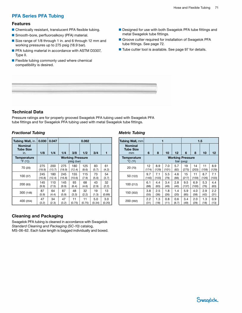
Hose and Flexible Tubing 71 HOSE /
FLEXIBLE TUBING
Technical DataPressure ratings are for properly grooved Swagelok PFA tubing used with Swagelok PFA tube fittings and for Swagelok PFA tubing used with metal Swagelok tube fittings.
Fractional Tubing Metric Tubing
Tubing Wall, in. 0.030 0.047 0.062
Nominal Tube Size
in. 1/8 1/4 1/4 3/8 1/2 3/4 1
Temperature °F (°C)
Working Pressure psig (bar)
70 (20) 275 (18.9)
200 (13.7)
275 (18.9)
180 (12.4)
125 (8.6)
83 (5.7)
61 (4.2)
100 (37) 245 (16.8)
180 (12.4)
245 (16.8)
155 (10.6)
115 (7.9)
73 (5.0)
54 (3.7)
200 (93) 145 (9.9)
110 (7.5)
145 (9.9)
93 (6.4)
68 (4.6)
43 (2.9)
32 (2.2)
300 (148) 87 (5.9)
64 (4.4)
87 (5.9)
48 (3.3)
32 (2.2)
19 (1.3)
13 (0.89)
400 (204) 47 (3.2)
34 (2.3)
47 (3.2)
11 (0.75)
11 (0.75)
5.0 (0.34)
3.0 (0.20)
Tubing Wall, mm 1 1.5
Nominal Tube Size
mm 6 8 10 12 6 8 10 12
Temperature °C (°F)
Working Pressure bar (psig)
20 (70) 12 (174)
8.9 (129)
7.0 (101)
5.7 (82)
19 (275)
14 (203)
11 (159)
8.9 (129)
50 (122) 9.7 (140)
7.1 (103)
5.5 (79)
4.6 (66)
15 (217)
11 (159)
8.7 (126)
7.1 (103)
100 (212) 6.1 (88)
4.4 (63)
3.4 (49)
2.8 (40)
9.5 (137)
6.9 (100)
5.3 (76)
4.4 (63)
150 (302) 3.8 (55)
2.5 (36)
1.8 (26)
1.4 (20)
5.9 (85)
4.0 (58)
2.9 (42)
2.2 (31)
200 (392) 2.2 (31)
1.3 (18)
0.8 (11)
0.6 (8.7)
3.4 (49)
2.0 (29)
1.3 (18)
0.9 (13)
■Designed for use with both Swagelok PFA tube fittings and metal Swagelok tube fittings.
■Groove cutter required for installation of Swagelok PFA tube fittings. See page 72.
■Tube cutter tool is available. See page 97 for details.
■Chemically resistant, translucent PFA flexible tubing.
■Smooth-bore, perfluoroalkoxy (PFA) material.
■Size range of 1/8 through 1 in. and 6 through 12 mm and working pressures up to 275 psig (18.9 bar).
■PFA tubing material in accordance with ASTM D3307, Type II.
■Flexible tubing commonly used where chemical compatibility is desired.
PFA Series PFA Tubing
Features
Cleaning and PackagingSwagelok PFA tubing is cleaned in accordance with Swagelok Standard Cleaning and Packaging (SC‑10) catalog, MS-06-62. Each tube length is bagged individually and boxed.
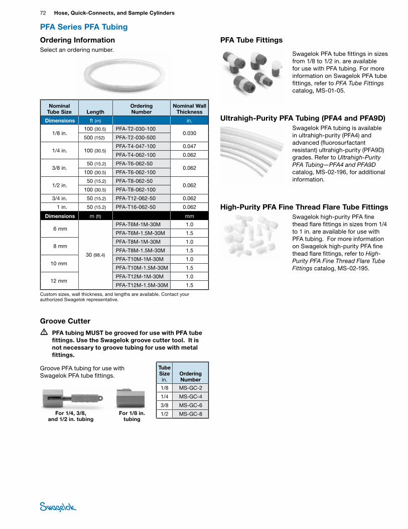
72 Hose, Quick-Connects, and Sample CylindersHO
SE /
FLEX
IBLE
TU
BING
Ordering InformationSelect an ordering number.
Custom sizes, wall thickness, and lengths are available. Contact your authorized Swagelok representative.
Nominal Tube Size Length
Ordering Number
Nominal Wall Thickness
Dimensions ft (m) in.
1/8 in.100 (30.5) PFA-T2-030-100
0.030 500 (152) PFA-T2-030-500
1/4 in. 100 (30.5) PFA-T4-047-100 0.047
PFA-T4-062-100 0.062
3/8 in. 50 (15.2) PFA-T6-062-50
0.062 100 (30.5) PFA-T6-062-100
1/2 in. 50 (15.2) PFA-T8-062-50
0.062 100 (30.5) PFA-T8-062-100
3/4 in. 50 (15.2) PFA-T12-062-50 0.062
1 in. 50 (15.2) PFA-T16-062-50 0.062
Dimensions m (ft) mm
6 mm
30 (98.4)
PFA-T6M-1M-30M 1.0
PFA-T6M-1.5M-30M 1.5
8 mmPFA-T8M-1M-30M 1.0
PFA-T8M-1.5M-30M 1.5
10 mm PFA-T10M-1M-30M 1.0
PFA-T10M-1.5M-30M 1.5
12 mm PFA-T12M-1M-30M 1.0
PFA-T12M-1.5M-30M 1.5
For 1/4, 3/8, and 1/2 in. tubing
For 1/8 in. tubing
Groove Cutter
• PFA tubing MUST be grooved for use with PFA tube fittings. Use the Swagelok groove cutter tool. It is not necessary to groove tubing for use with metal fittings.
Groove PFA tubing for use with Swagelok PFA tube fittings.
Tube Size in.
Ordering Number
1/8 MS-GC-2
1/4 MS-GC-4
3/8 MS-GC-6
1/2 MS-GC-8
PFA Series PFA Tubing
PFA Tube Fittings
Swagelok PFA tube fittings in sizes from 1/8 to 1/2 in. are available for use with PFA tubing. For more information on Swagelok PFA tube fittings, refer to PFA Tube Fittings catalog, MS-01-05.
Ultrahigh-Purity PFA Tubing (PFA4 and PFA9D)Swagelok PFA tubing is available in ultrahigh-purity (PFA4) and advanced (fluorosurfactant resistant) ultrahigh-purity (PFA9D) grades. Refer to Ultrahigh‑Purity PFA Tubing—PFA4 and PFA9D catalog, MS-02-196, for additional information.
High-Purity PFA Fine Thread Flare Tube FittingsSwagelok high-purity PFA fine thead flare fittings in sizes from 1/4 to 1 in. are available for use with PFA tubing. For more information on Swagelok high-purity PFA fine thead flare fittings, refer to High‑Purity PFA Fine Thread Flare Tube Fittings catalog, MS-02-195.
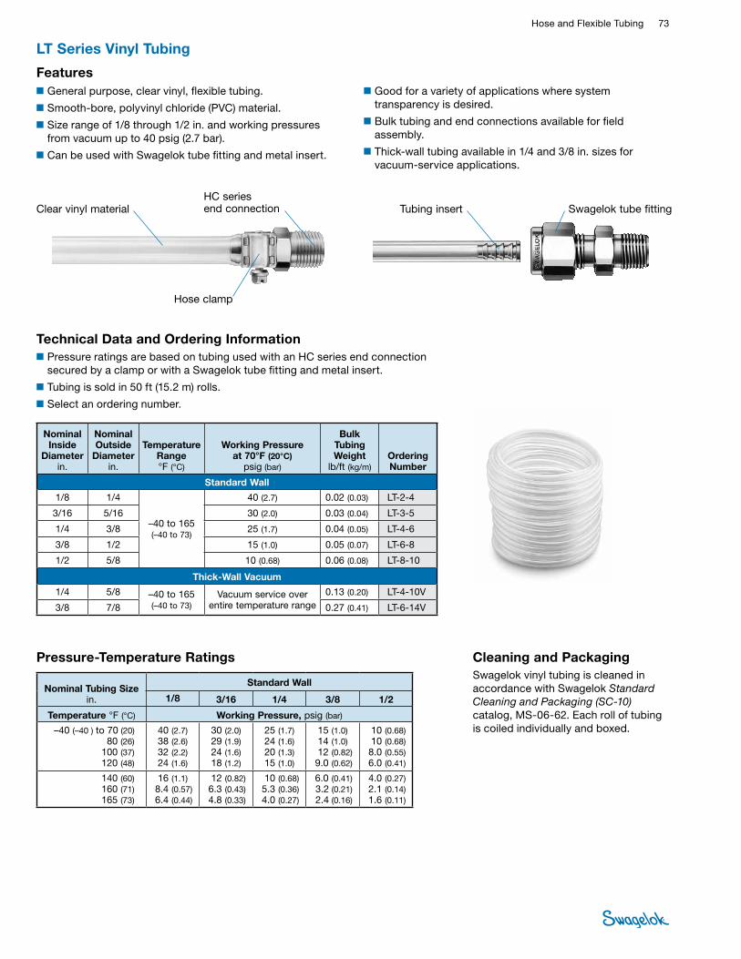
Hose and Flexible Tubing 73 HOSE /
FLEXIBLE TUBING
LT Series Vinyl Tubing
■General purpose, clear vinyl, flexible tubing.
■Smooth-bore, polyvinyl chloride (PVC) material.
■Size range of 1/8 through 1/2 in. and working pressures from vacuum up to 40 psig (2.7 bar).
■Can be used with Swagelok tube fitting and metal insert.
Technical Data and Ordering Information■Pressure ratings are based on tubing used with an HC series end connection
secured by a clamp or with a Swagelok tube fitting and metal insert.
■ Tubing is sold in 50 ft (15.2 m) rolls.
■ Select an ordering number.
■Good for a variety of applications where system transparency is desired.
■Bulk tubing and end connections available for field assembly.
■Thick-wall tubing available in 1/4 and 3/8 in. sizes for vacuum-service applications.
Features
Nominal Inside
Diameter in.
Nominal Outside
Diameter in.
Temperature Range°F (°C)
Working Pressure at 70°F (20°C)
psig (bar)
Bulk Tubing Weight
lb/ft (kg/m)Ordering Number
Standard Wall
1/8 1/4
–40 to 165 (–40 to 73)
40 (2.7) 0.02 (0.03) LT-2-4
3/16 5/16 30 (2.0) 0.03 (0.04) LT-3-5
1/4 3/8 25 (1.7) 0.04 (0.05) LT-4-6
3/8 1/2 15 (1.0) 0.05 (0.07) LT-6-8
1/2 5/8 10 (0.68) 0.06 (0.08) LT-8-10
Thick-Wall Vacuum
1/4 5/8 –40 to 165 (–40 to 73)
Vacuum service over entire temperature range
0.13 (0.20) LT-4-10V
3/8 7/8 0.27 (0.41) LT-6-14V
Clear vinyl material Tubing insert Swagelok tube fittingHC series end connection
Hose clamp
Cleaning and PackagingSwagelok vinyl tubing is cleaned in accordance with Swagelok Standard Cleaning and Packaging (SC‑10) catalog, MS-06-62. Each roll of tubing is coiled individually and boxed.
Nominal Tubing Size in.
Standard Wall
1/8 3/16 1/4 3/8 1/2
Temperature °F (°C) Working Pressure, psig (bar)
–40 (–40 ) to 70 (20) 80 (26)
100 (37) 120 (48)
40 (2.7) 38 (2.6)32 (2.2) 24 (1.6)
30 (2.0)29 (1.9)24 (1.6)18 (1.2)
25 (1.7) 24 (1.6)20 (1.3)15 (1.0)
15 (1.0) 14 (1.0)12 (0.82) 9.0 (0.62)
10 (0.68)10 (0.68)8.0 (0.55)6.0 (0.41)
140 (60) 160 (71) 165 (73)
16 (1.1) 8.4 (0.57)6.4 (0.44)
12 (0.82) 6.3 (0.43)4.8 (0.33)
10 (0.68) 5.3 (0.36)4.0 (0.27)
6.0 (0.41) 3.2 (0.21)2.4 (0.16)
4.0 (0.27) 2.1 (0.14)1.6 (0.11)
Pressure-Temperature Ratings
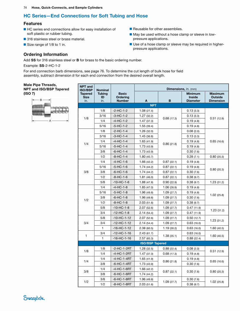
74 Hose, Quick-Connects, and Sample CylindersHO
SE /
FLEX
IBLE
TU
BING
HC Series—End Connections for Soft Tubing and Hose
NPT and ISO/BSP Tapered
Size in.
Nominal Tubing
ID in.
Basic Ordering Number
Dimensions, in. (mm)
A B
Minimum Inside
Diameter
Maximum Outside
DimensionNPT
1/8
1/8 -2-HC-1-2 1.08 (27.4)
0.68 (17.3)
0.13 (3.3)
0.51 (12.9) 3/16 -3-HC-1-2 1.27 (32.2) 0.13 (3.3)
1/4 -4-HC-1-2 1.47 (37.3) 0.19 (4.8)
5/16 -5-HC-1-2 1.55 (39.4) 0.19 (4.8)
1/4
1/8 -2-HC-1-4 1.26 (32.0)
0.86 (21.8)
0.08 (2.0)
0.65 (16.6)
3/16 -3-HC-1-4 1.45 (36.8) 0.13 (3.3)
1/4 -4-HC-1-4 1.65 (41.9) 0.19 (4.8)
5/16 -5-HC-1-4 1.73 (43.9) 0.19 (4.8)
3/8 -6-HC-1-4 1.73 (43.9) 0.30 (7.6)
1/2 -8-HC-1-4 1.80 (45.7) 0.28 (7.1) 0.80 (20.3)
3/8
1/4 -4-HC-1-6 1.66 (42.2) 0.87 (22.1) 0.19 (4.8)
0.80 (20.3) 5/16 -5-HC-1-6 1.74 (44.2) 0.87 (22.1) 0.19 (4.8)
3/8 -6-HC-1-6 1.74 (44.2) 0.87 (22.1) 0.30 (7.6)
1/2 -8-HC-1-6 1.81 (46.0) 0.87 (22.1) 0.38 (9.7)
5/8 -10-HC-1-6 1.88 (47.8) 0.90 (22.9) 0.38 (9.7) 1.23 (31.2)
1/2
1/4 -4-HC-1-8 1.85 (47.0) 1.06 (26.9) 0.19 (4.8)
1.02 (25.8) 5/16 -5-HC-1-8 1.96 (49.8) 1.09 (27.7) 0.19 (4.8)
3/8 -6-HC-1-8 1.96 (49.8) 1.09 (27.7) 0.30 (7.6)
1/2 -8-HC-1-8 2.03 (51.6) 1.09 (27.7) 0.38 (9.7)
5/8 -10-HC-1-8 2.07 (52.6) 1.09 (27.7) 0.47 (11.9) 1.23 (31.2)
3/4 -12-HC-1-8 2.14 (54.4) 1.09 (27.7) 0.47 (11.9)
3/4
5/8 -10-HC-1-12 2.07 (52.6) 1.09 (27.7) 0.50 (12.7)1.23 (31.2)
3/4 -12-HC-1-12 2.14 (54.4) 1.09 (27.7) 0.63 (16.0)
1 -16-HC-1-12 2.38 (60.5) 1.19 (30.2) 0.63 (16.0) 1.60 (40.5)
13/4 -12-HC-1-16 2.43 (61.7)
1.38 (35.1)0.63 (16.0)
1.60 (40.5)1 -16-HC-1-16 2.57 (65.3) 0.88 (22.4)
ISO/BSP Tapered
1/81/8 -2-HC-1-2RT 1.28 (32.5) 0.88 (22.4) 0.08 (2.0)
0.51 (12.9) 1/4 -4-HC-1-2RT 1.47 (37.3) 0.68 (17.3) 0.19 (4.8)
1/41/4 -4-HC-1-4RT 1.65 (41.9)
0.86 (21.8)0.19 (4.8)
0.65 (16.6) 3/8 -6-HC-1-4RT 1.73 (43.9) 0.30 (7.6)
3/81/4 -4-HC-1-6RT 1.66 (42.2)
0.87 (22.1) 0.30 (7.6) 0.80 (20.3) 3/8 -6-HC-1-6RT 1.74 (44.2)
1/23/8 -6-HC-1-8RT 1.96 (49.8)
1.09 (27.7)0.30 (7.6)
1.02 (25.8) 1/2 -8-HC-1-8RT 2.03 (51.6) 0.38 (9.7)
Male Pipe Threads, NPT and ISO/BSP Tapered (ISO 7)
A
B
Features■HC series end connections allow for easy installation of
soft plastic or rubber tubing.
■316 stainless steel or brass material.
■Size range of 1/8 to 1 in.
Ordering InformationAdd SS for 316 stainless steel or B for brass to the basic ordering number.
Example: SS-2-HC-1-2
For end connection barb dimensions, see page 76. To determine the cut length of bulk hose for field assembly, subtract dimension B for each end connection from the desired overall length.
■Reusable for other assemblies.
■May be used without a hose clamp or sleeve in low-pressure applications.
■Use of a hose clamp or sleeve may be required in higher-pressure applications.
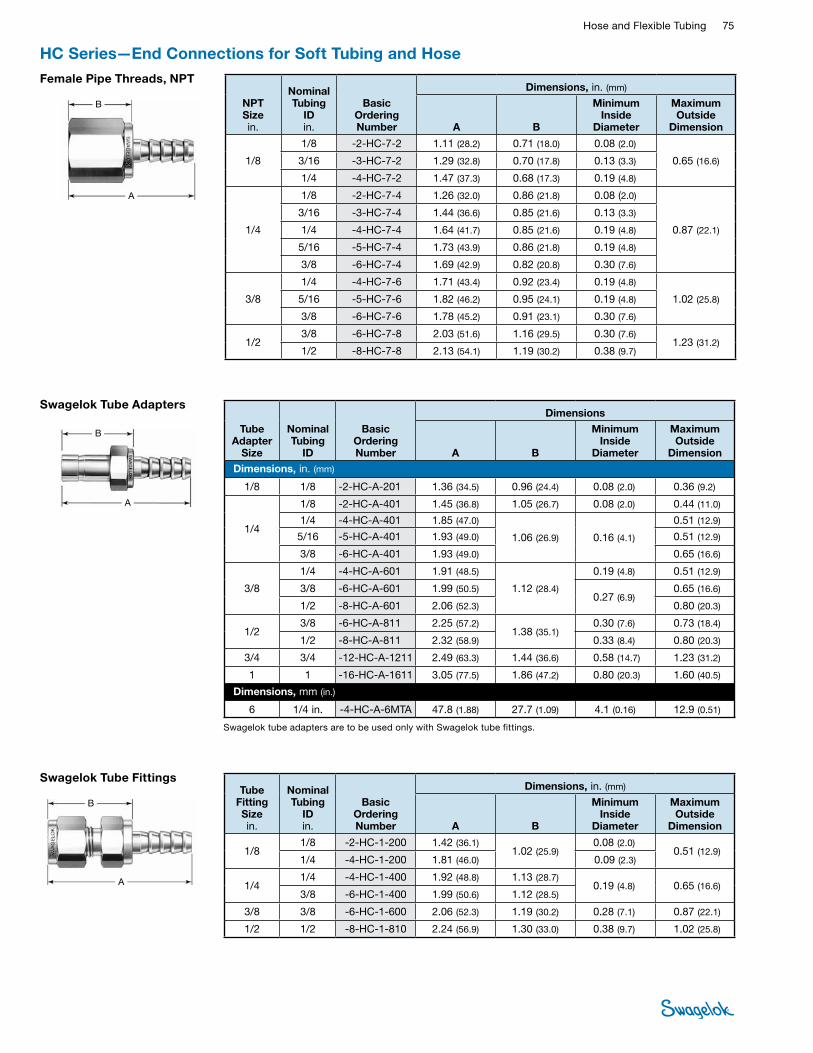
Hose and Flexible Tubing 75 HOSE /
FLEXIBLE TUBING
HC Series—End Connections for Soft Tubing and Hose
Swagelok Tube Adapters
Swagelok tube adapters are to be used only with Swagelok tube fittings.
Tube Adapter
Size
Nominal Tubing
ID
Basic Ordering Number
Dimensions
A B
Minimum Inside
Diameter
Maximum Outside
Dimension Dimensions, in. (mm)
1/8 1/8 -2-HC-A-201 1.36 (34.5) 0.96 (24.4) 0.08 (2.0) 0.36 (9.2)
1/4
1/8 -2-HC-A-401 1.45 (36.8) 1.05 (26.7) 0.08 (2.0) 0.44 (11.0)
1/4 -4-HC-A-401 1.85 (47.0)
1.06 (26.9) 0.16 (4.1)
0.51 (12.9)
5/16 -5-HC-A-401 1.93 (49.0) 0.51 (12.9)
3/8 -6-HC-A-401 1.93 (49.0) 0.65 (16.6)
3/8
1/4 -4-HC-A-601 1.91 (48.5)
1.12 (28.4)
0.19 (4.8) 0.51 (12.9)
3/8 -6-HC-A-601 1.99 (50.5)0.27 (6.9)
0.65 (16.6)
1/2 -8-HC-A-601 2.06 (52.3) 0.80 (20.3)
1/23/8 -6-HC-A-811 2.25 (57.2)
1.38 (35.1)0.30 (7.6) 0.73 (18.4)
1/2 -8-HC-A-811 2.32 (58.9) 0.33 (8.4) 0.80 (20.3)
3/4 3/4 -12-HC-A-1211 2.49 (63.3) 1.44 (36.6) 0.58 (14.7) 1.23 (31.2)
1 1 -16-HC-A-1611 3.05 (77.5) 1.86 (47.2) 0.80 (20.3) 1.60 (40.5)
Dimensions, mm (in.)
6 1/4 in. -4-HC-A-6MTA 47.8 (1.88) 27.7 (1.09) 4.1 (0.16) 12.9 (0.51)
A
B
Female Pipe Threads, NPT
NPT Size in.
Nominal Tubing
ID in.
Basic Ordering Number
Dimensions, in. (mm)
A B
Minimum Inside
Diameter
Maximum Outside
Dimension
1/8
1/8 -2-HC-7-2 1.11 (28.2) 0.71 (18.0) 0.08 (2.0)
0.65 (16.6) 3/16 -3-HC-7-2 1.29 (32.8) 0.70 (17.8) 0.13 (3.3)
1/4 -4-HC-7-2 1.47 (37.3) 0.68 (17.3) 0.19 (4.8)
1/4
1/8 -2-HC-7-4 1.26 (32.0) 0.86 (21.8) 0.08 (2.0)
0.87 (22.1)
3/16 -3-HC-7-4 1.44 (36.6) 0.85 (21.6) 0.13 (3.3)
1/4 -4-HC-7-4 1.64 (41.7) 0.85 (21.6) 0.19 (4.8)
5/16 -5-HC-7-4 1.73 (43.9) 0.86 (21.8) 0.19 (4.8)
3/8 -6-HC-7-4 1.69 (42.9) 0.82 (20.8) 0.30 (7.6)
3/8
1/4 -4-HC-7-6 1.71 (43.4) 0.92 (23.4) 0.19 (4.8)
1.02 (25.8) 5/16 -5-HC-7-6 1.82 (46.2) 0.95 (24.1) 0.19 (4.8)
3/8 -6-HC-7-6 1.78 (45.2) 0.91 (23.1) 0.30 (7.6)
1/23/8 -6-HC-7-8 2.03 (51.6) 1.16 (29.5) 0.30 (7.6)
1.23 (31.2)1/2 -8-HC-7-8 2.13 (54.1) 1.19 (30.2) 0.38 (9.7)
A
B
Swagelok Tube FittingsTube
Fitting Size in.
Nominal Tubing
ID in.
Basic Ordering Number
Dimensions, in. (mm)
A B
Minimum Inside
Diameter
Maximum Outside
Dimension
1/8 1/8 -2-HC-1-200 1.42 (36.1)
1.02 (25.9)0.08 (2.0)
0.51 (12.9) 1/4 -4-HC-1-200 1.81 (46.0) 0.09 (2.3)
1/41/4 -4-HC-1-400 1.92 (48.8) 1.13 (28.7)
0.19 (4.8) 0.65 (16.6)3/8 -6-HC-1-400 1.99 (50.6) 1.12 (28.5)
3/8 3/8 -6-HC-1-600 2.06 (52.3) 1.19 (30.2) 0.28 (7.1) 0.87 (22.1)
1/2 1/2 -8-HC-1-810 2.24 (56.9) 1.30 (33.0) 0.38 (9.7) 1.02 (25.8)
A
B
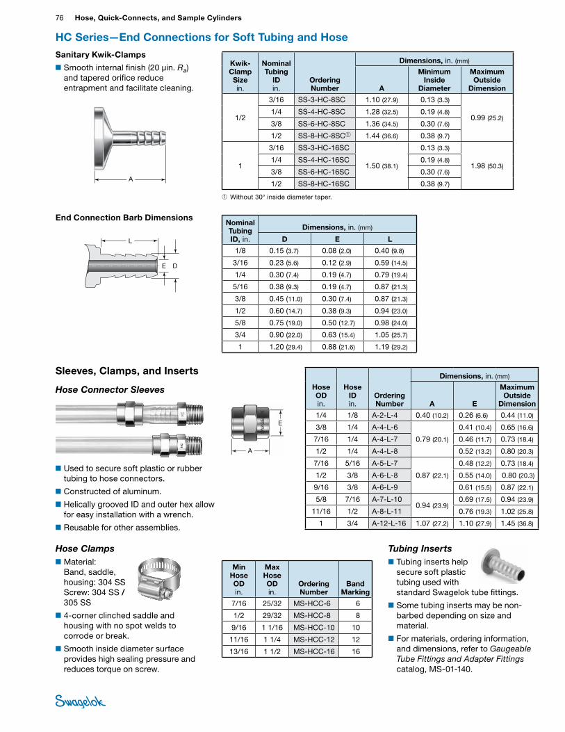
76 Hose, Quick-Connects, and Sample CylindersHO
SE /
FLEX
IBLE
TU
BING
HC Series—End Connections for Soft Tubing and Hose
Kwik-Clamp Size in.
Nominal Tubing
ID in.
Ordering Number
Dimensions, in. (mm)
A
Minimum Inside
Diameter
Maximum Outside
Dimension
1/2
3/16 SS-3-HC-8SC 1.10 (27.9) 0.13 (3.3)
0.99 (25.2)1/4 SS-4-HC-8SC 1.28 (32.5) 0.19 (4.8)
3/8 SS-6-HC-8SC 1.36 (34.5) 0.30 (7.6)
1/2 SS-8-HC-8SC➀ 1.44 (36.6) 0.38 (9.7)
1
3/16 SS-3-HC-16SC
1.50 (38.1)
0.13 (3.3)
1.98 (50.3)1/4 SS-4-HC-16SC 0.19 (4.8)
3/8 SS-6-HC-16SC 0.30 (7.6)
1/2 SS-8-HC-16SC 0.38 (9.7)
Sanitary Kwik-Clamps
■Smooth internal finish (20 µin. Ra) and tapered orifice reduce entrapment and facilitate cleaning.
A
Sleeves, Clamps, and Inserts
Hose Connector Sleeves
■Used to secure soft plastic or rubber tubing to hose connectors.
■Constructed of aluminum.
■Helically grooved ID and outer hex allow for easy installation with a wrench.
■Reusable for other assemblies.
Hose OD in.
Hose ID in.
Ordering Number
Dimensions, in. (mm)
A E
Maximum Outside
Dimension
1/4 1/8 A-2-L-4 0.40 (10.2) 0.26 (6.6) 0.44 (11.0)
3/8 1/4 A-4-L-6
0.79 (20.1)
0.41 (10.4) 0.65 (16.6)
7/16 1/4 A-4-L-7 0.46 (11.7) 0.73 (18.4)
1/2 1/4 A-4-L-8 0.52 (13.2) 0.80 (20.3)
7/16 5/16 A-5-L-7
0.87 (22.1)
0.48 (12.2) 0.73 (18.4)
1/2 3/8 A-6-L-8 0.55 (14.0) 0.80 (20.3)
9/16 3/8 A-6-L-9 0.61 (15.5) 0.87 (22.1)
5/8 7/16 A-7-L-10 0.94 (23.9)
0.69 (17.5) 0.94 (23.9)
11/16 1/2 A-8-L-11 0.76 (19.3) 1.02 (25.8)
1 3/4 A-12-L-16 1.07 (27.2) 1.10 (27.9) 1.45 (36.8)
E
A
Hose Clamps■Material:
Band, saddle, housing: 304 SS Screw: 304 SS / 305 SS
■4-corner clinched saddle and housing with no spot welds to corrode or break.
■Smooth inside diameter surface provides high sealing pressure and reduces torque on screw.
Min Hose OD in.
Max Hose OD in.
Ordering Number
Band Marking
7/16 25/32 MS-HCC-6 6
1/2 29/32 MS-HCC-8 8
9/16 1 1/16 MS-HCC-10 10
11/16 1 1/4 MS-HCC-12 12
13/16 1 1/2 MS-HCC-16 16
➀ Without 30° inside diameter taper.
End Connection Barb DimensionsNominal Tubing ID, in.
Dimensions, in. (mm)
D E L
1/8 0.15 (3.7) 0.08 (2.0) 0.40 (9.8)
3/16 0.23 (5.6) 0.12 (2.9) 0.59 (14.5)
1/4 0.30 (7.4) 0.19 (4.7) 0.79 (19.4)
5/16 0.38 (9.3) 0.19 (4.7) 0.87 (21.3)
3/8 0.45 (11.0) 0.30 (7.4) 0.87 (21.3)
1/2 0.60 (14.7) 0.38 (9.3) 0.94 (23.0)
5/8 0.75 (19.0) 0.50 (12.7) 0.98 (24.0)
3/4 0.90 (22.0) 0.63 (15.4) 1.05 (25.7)
1 1.20 (29.4) 0.88 (21.6) 1.19 (29.2)
DE
L
Tubing Inserts■Tubing inserts help
secure soft plastic tubing used with standard Swagelok tube fittings.
■Some tubing inserts may be non-barbed depending on size and material.
■For materials, ordering information, and dimensions, refer to Gaugeable Tube Fittings and Adapter Fittings catalog, MS-01-140.
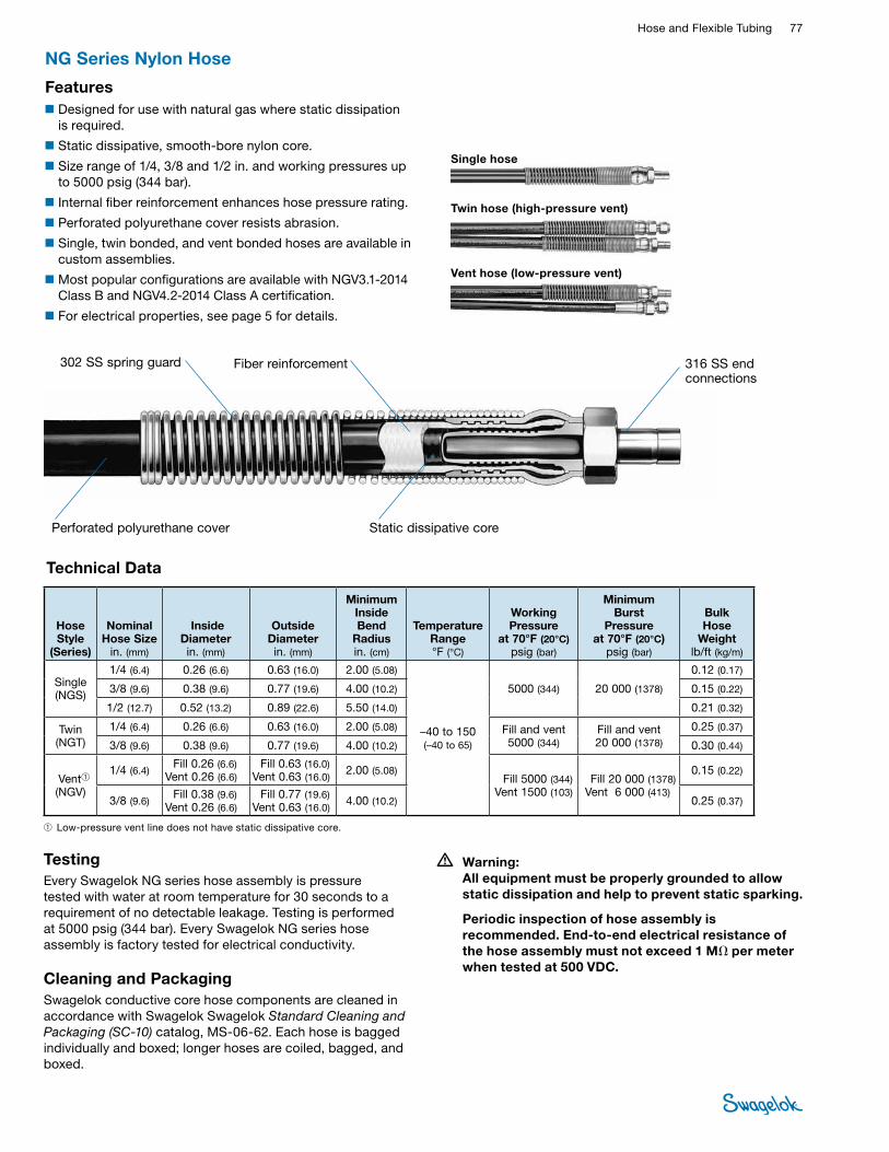
Hose and Flexible Tubing 77 HOSE /
FLEXIBLE TUBING
TestingEvery Swagelok NG series hose assembly is pressure tested with water at room temperature for 30 seconds to a requirement of no detectable leakage. Testing is performed at 5000 psig (344 bar). Every Swagelok NG series hose assembly is factory tested for electrical conductivity.
Cleaning and PackagingSwagelok conductive core hose components are cleaned in accordance with Swagelok Swagelok Standard Cleaning and Packaging (SC‑10) catalog, MS-06-62. Each hose is bagged individually and boxed; longer hoses are coiled, bagged, and boxed.
• Warning: All equipment must be properly grounded to allow static dissipation and help to prevent static sparking.
Periodic inspection of hose assembly is recommended. End-to-end electrical resistance of the hose assembly must not exceed 1 MΩ per meter when tested at 500 VDC.
NG Series Nylon Hose
Perforated polyurethane cover Static dissipative core
Fiber reinforcement302 SS spring guard 316 SS end connections
Technical Data
➀ Low-pressure vent line does not have static dissipative core.
■Designed for use with natural gas where static dissipation is required.
■Static dissipative, smooth-bore nylon core.
■Size range of 1/4, 3/8 and 1/2 in. and working pressures up to 5000 psig (344 bar).
■Internal fiber reinforcement enhances hose pressure rating.
■Perforated polyurethane cover resists abrasion.
■Single, twin bonded, and vent bonded hoses are available in custom assemblies.
■Most popular configurations are available with NGV3.1-2014 Class B and NGV4.2-2014 Class A certification.
■For electrical properties, see page 5 for details.
Single hose
Twin hose (high-pressure vent)
Vent hose (low-pressure vent)
Features
Hose Style
(Series)
Nominal Hose Size
in. (mm)
Inside Diameter in. (mm)
Outside Diameter in. (mm)
Minimum Inside Bend
Radiusin. (cm)
TemperatureRange °F (°C)
Working Pressure
at 70°F (20°C) psig (bar)
Minimum Burst
Pressure at 70°F (20°C)
psig (bar)
Bulk Hose
Weight lb/ft (kg/m)
Single(NGS)
1/4 (6.4) 0.26 (6.6) 0.63 (16.0) 2.00 (5.08)
–40 to 150 (–40 to 65)
5000 (344) 20 000 (1378)
0.12 (0.17)
3/8 (9.6) 0.38 (9.6) 0.77 (19.6) 4.00 (10.2) 0.15 (0.22)
1/2 (12.7) 0.52 (13.2) 0.89 (22.6) 5.50 (14.0) 0.21 (0.32)
Twin (NGT)
1/4 (6.4) 0.26 (6.6) 0.63 (16.0) 2.00 (5.08) Fill and vent 5000 (344)
Fill and vent 20 000 (1378)
0.25 (0.37)
3/8 (9.6) 0.38 (9.6) 0.77 (19.6) 4.00 (10.2) 0.30 (0.44)
Vent➀ (NGV)
1/4 (6.4) Fill 0.26 (6.6) Vent 0.26 (6.6)
Fill 0.63 (16.0) Vent 0.63 (16.0)
2.00 (5.08) Fill 5000 (344)
Vent 1500 (103) Fill 20 000 (1378)
Vent 6 000 (413)
0.15 (0.22)
3/8 (9.6) Fill 0.38 (9.6) Vent 0.26 (6.6)
Fill 0.77 (19.6) Vent 0.63 (16.0)
4.00 (10.2) 0.25 (0.37)
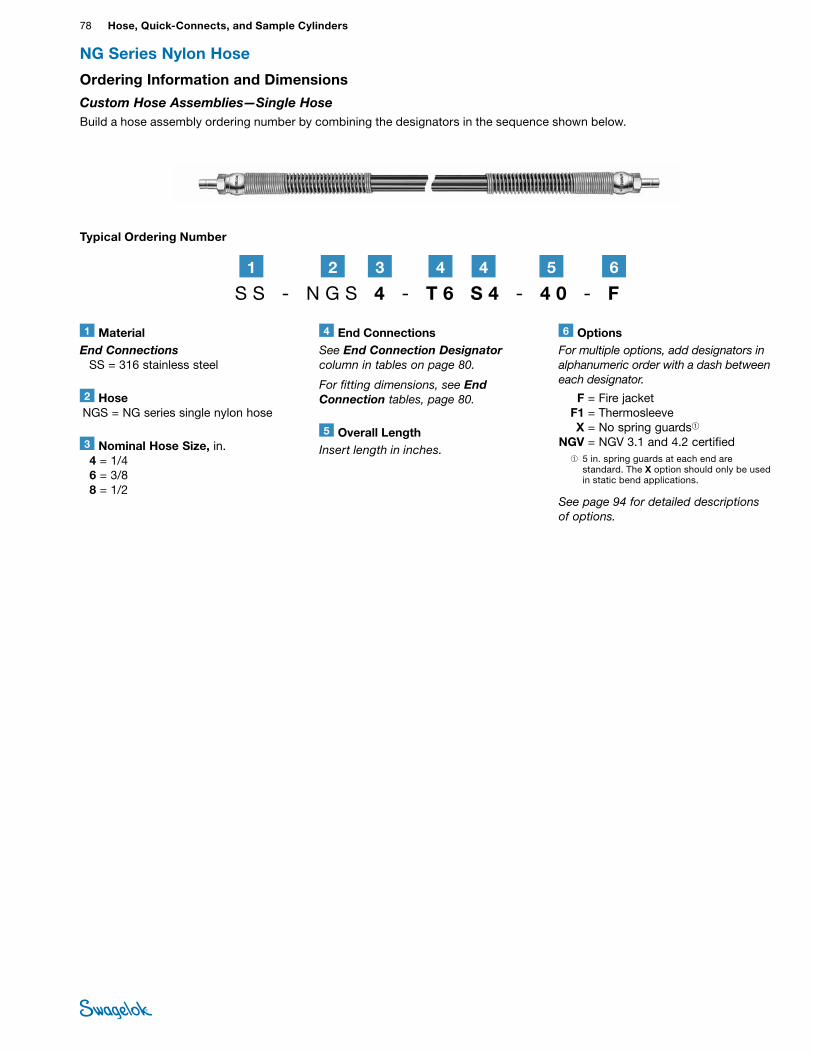
78 Hose, Quick-Connects, and Sample CylindersHO
SE /
FLEX
IBLE
TU
BING
NG Series Nylon Hose
Typical Ordering Number
Ordering Information and Dimensions
Custom Hose Assemblies—Single Hose Build a hose assembly ordering number by combining the designators in the sequence shown below.
2 Hose NGS = NG series single nylon hose
3 Nominal Hose Size, in. 4 = 1/4 6 = 3/8 8 = 1/2
4 End ConnectionsSee End Connection Designator column in tables on page 80.
For fitting dimensions, see End Connection tables, page 80.
6 OptionsFor multiple options, add designators in alphanumeric order with a dash between each designator.
F = Fire jacket F1 = Thermosleeve X = No spring guards➀ NGV = NGV 3.1 and 4.2 certified ➀ 5 in. spring guards at each end are
standard. The X option should only be used in static bend applications.
See page 94 for detailed descriptions of options.
5 Overall LengthInsert length in inches.
S S - N G S 4 - T 6 S 4 - 4 0 - F2 61 3 44 5
1 MaterialEnd Connections SS = 316 stainless steel
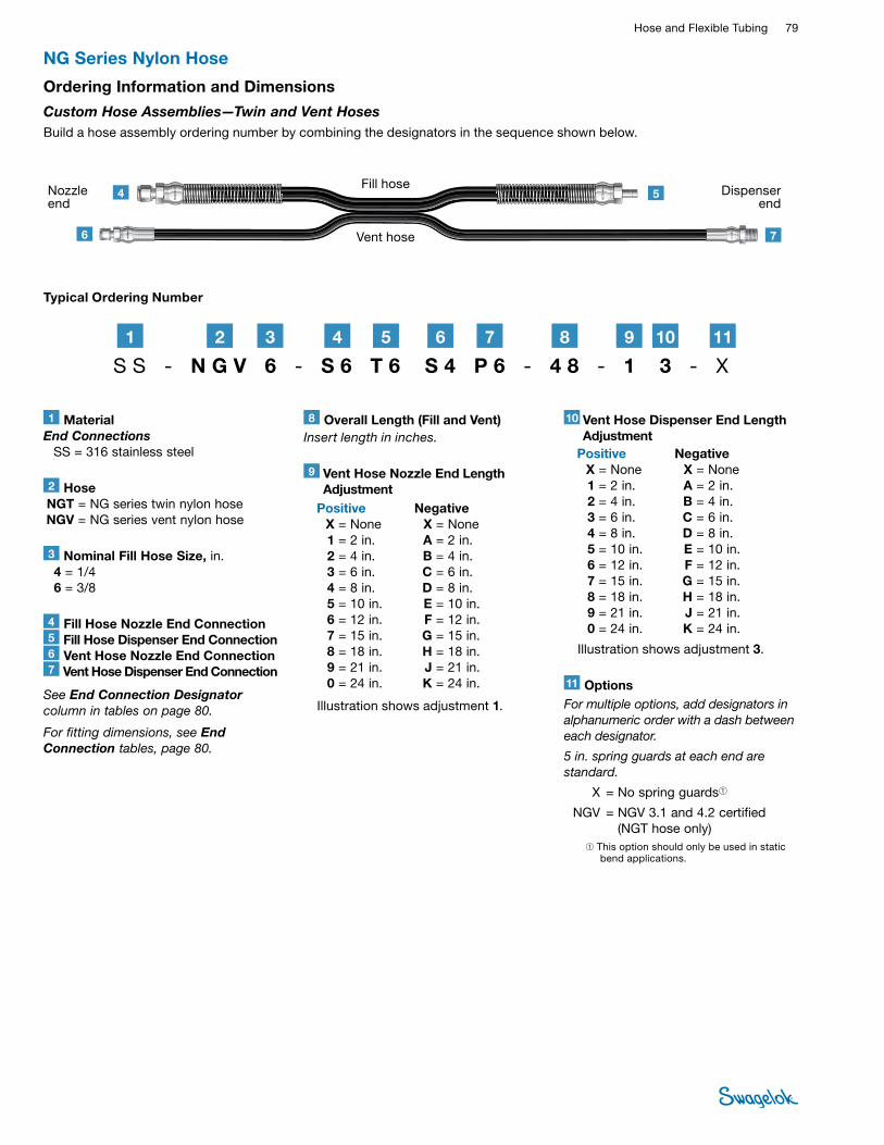
Hose and Flexible Tubing 79 HOSE /
FLEXIBLE TUBING
NG Series Nylon Hose
Ordering Information and Dimensions
Custom Hose Assemblies—Twin and Vent Hoses Build a hose assembly ordering number by combining the designators in the sequence shown below.
Fill hose
Vent hose
Nozzle end
4 5
76
Dispenser end
Typical Ordering Number
11 OptionsFor multiple options, add designators in alphanumeric order with a dash between each designator.
5 in. spring guards at each end are standard.
X = No spring guards➀
NGV = NGV 3.1 and 4.2 certified (NGT hose only)
➀ This option should only be used in static bend applications.
S S - N G V 6 - S 6 T 6 S 4 P 6 - 4 8 - 1 3 - X
1 MaterialEnd Connections SS = 316 stainless steel
2 Hose NGT = NG series twin nylon hose NGV = NG series vent nylon hose
3 Nominal Fill Hose Size, in. 4 = 1/4 6 = 3/8
4 Fill Hose Nozzle End Connection5 Fill Hose Dispenser End Connection6 Vent Hose Nozzle End Connection7 Vent Hose Dispenser End Connection
See End Connection Designator column in tables on page 80.
For fitting dimensions, see End Connection tables, page 80.
2 71 3 54 6
8 Overall Length (Fill and Vent)Insert length in inches.
8 9 1110
Positive X = None 1 = 2 in. 2 = 4 in. 3 = 6 in. 4 = 8 in. 5 = 10 in. 6 = 12 in. 7 = 15 in. 8 = 18 in. 9 = 21 in. 0 = 24 in.
Negative X = None A = 2 in. B = 4 in. C = 6 in. D = 8 in. E = 10 in. F = 12 in. G = 15 in. H = 18 in. J = 21 in. K = 24 in.
9 Vent Hose Nozzle End Length Adjustment
Illustration shows adjustment 1.
Positive X = None 1 = 2 in. 2 = 4 in. 3 = 6 in. 4 = 8 in. 5 = 10 in. 6 = 12 in. 7 = 15 in. 8 = 18 in. 9 = 21 in. 0 = 24 in.
Negative X = None A = 2 in. B = 4 in. C = 6 in. D = 8 in. E = 10 in. F = 12 in. G = 15 in. H = 18 in. J = 21 in. K = 24 in.
10 Vent Hose Dispenser End Length Adjustment
Illustration shows adjustment 3.
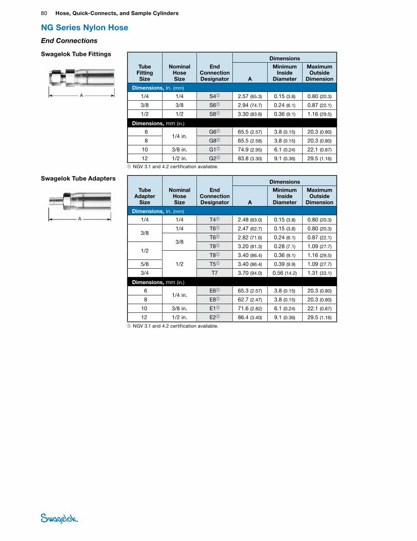
80 Hose, Quick-Connects, and Sample CylindersHO
SE /
FLEX
IBLE
TU
BING
NG Series Nylon Hose
End Connections
Swagelok Tube Fittings
A
Swagelok Tube Adapters
A
TubeFitting Size
Nominal Hose Size
End Connection Designator
Dimensions
A
Minimum Inside
Diameter
Maximum Outside
Dimension
Dimensions, in. (mm)
1/4 1/4 S4➀ 2.57 (65.3) 0.15 (3.8) 0.80 (20.3)
3/8 3/8 S6➀ 2.94 (74.7) 0.24 (6.1) 0.87 (22.1)
1/2 1/2 S8➀ 3.30 (83.8) 0.36 (9.1) 1.16 (29.5)
Dimensions, mm (in.)
61/4 in.
G6➀ 65.5 (2.57) 3.8 (0.15) 20.3 (0.80)
8 G8➀ 65.5 (2.58) 3.8 (0.15) 20.3 (0.80)
10 3/8 in. G1➀ 74.9 (2.95) 6.1 (0.24) 22.1 (0.87)
12 1/2 in. G2➀ 83.8 (3.30) 9.1 (0.36) 29.5 (1.16)
Tube Adapter
Size
Nominal Hose Size
End Connection Designator
Dimensions
A
Minimum Inside
Diameter
Maximum Outside
Dimension
Dimensions, in. (mm)
1/4 1/4 T4➀ 2.48 (63.0) 0.15 (3.8) 0.80 (20.3)
3/8 1/4 T6➀ 2.47 (62.7) 0.15 (3.8) 0.80 (20.3)
3/8 T6➀ 2.82 (71.6) 0.24 (6.1) 0.87 (22.1)
1/2T8➀ 3.20 (81.3) 0.28 (7.1) 1.09 (27.7)
1/2
T8➀ 3.40 (86.4) 0.36 (9.1) 1.16 (29.5)
5/8 T5➀ 3.40 (86.4) 0.39 (9.9) 1.09 (27.7)
3/4 T7 3.70 (94.0) 0.56 (14.2) 1.31 (33.1)
Dimensions, mm (in.)
61/4 in.
E6➀ 65.3 (2.57) 3.8 (0.15) 20.3 (0.80)
8 E8➀ 62.7 (2.47) 3.8 (0.15) 20.3 (0.80)
10 3/8 in. E1➀ 71.6 (2.82) 6.1 (0.24) 22.1 (0.87)
12 1/2 in. E2➀ 86.4 (3.40) 9.1 (0.36) 29.5 (1.16)
➀ NGV 3.1 and 4.2 certification available.
➀ NGV 3.1 and 4.2 certification available.
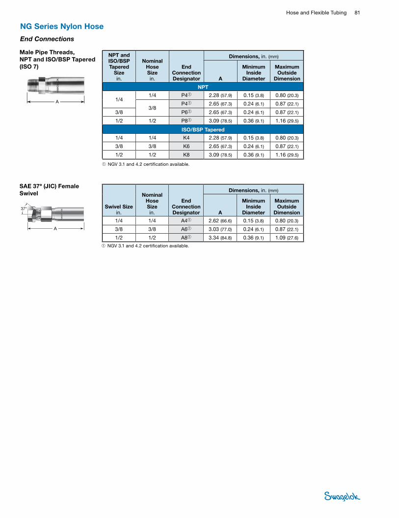
Hose and Flexible Tubing 81 HOSE /
FLEXIBLE TUBING
Swivel Size in.
Nominal Hose Size in.
End Connection Designator
Dimensions, in. (mm)
A
Minimum Inside
Diameter
Maximum Outside
Dimension
1/4 1/4 A4➀ 2.62 (66.6) 0.15 (3.8) 0.80 (20.3)
3/8 3/8 A6➀ 3.03 (77.0) 0.24 (6.1) 0.87 (22.1)
1/2 1/2 A8➀ 3.34 (84.8) 0.36 (9.1) 1.09 (27.6)
SAE 37o (JIC) Female Swivel
NG Series Nylon Hose
End Connections
➀ NGV 3.1 and 4.2 certification available.
A
Male Pipe Threads, NPT and ISO/BSP Tapered (ISO 7)
A
NPT and ISO/BSP Tapered
Size in.
Nominal Hose Size in.
End Connection Designator
Dimensions, in. (mm)
A
Minimum Inside
Diameter
Maximum Outside
Dimension
NPT
1/4 1/4 P4➀ 2.28 (57.9) 0.15 (3.8) 0.80 (20.3)
3/8 P4➀ 2.65 (67.3) 0.24 (6.1) 0.87 (22.1)
3/8 P6➀ 2.65 (67.3) 0.24 (6.1) 0.87 (22.1)
1/2 1/2 P8➀ 3.09 (78.5) 0.36 (9.1) 1.16 (29.5)
ISO/BSP Tapered
1/4 1/4 K4 2.28 (57.9) 0.15 (3.8) 0.80 (20.3)
3/8 3/8 K6 2.65 (67.3) 0.24 (6.1) 0.87 (22.1)
1/2 1/2 K8 3.09 (78.5) 0.36 (9.1) 1.16 (29.5)
➀ NGV 3.1 and 4.2 certification available.
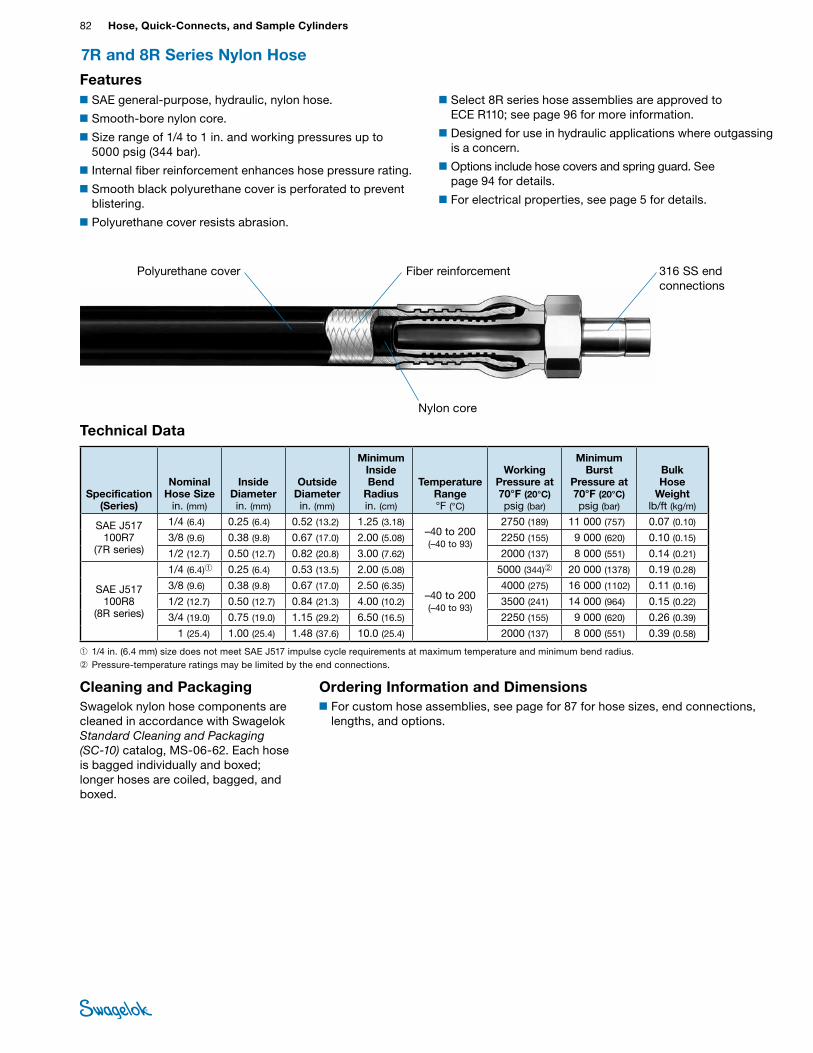
82 Hose, Quick-Connects, and Sample CylindersHO
SE /
FLEX
IBLE
TU
BING
7R and 8R Series Nylon Hose
■SAE general-purpose, hydraulic, nylon hose.
■Smooth-bore nylon core.
■Size range of 1/4 to 1 in. and working pressures up to 5000 psig (344 bar).
■Internal fiber reinforcement enhances hose pressure rating.
■Smooth black polyurethane cover is perforated to prevent blistering.
■Polyurethane cover resists abrasion.
■Select 8R series hose assemblies are approved to ECE R110; see page 96 for more information.
■Designed for use in hydraulic applications where outgassing is a concern.
■Options include hose covers and spring guard. See page 94 for details.
■For electrical properties, see page 5 for details.
Features
Technical Data
Specification (Series)
Nominal Hose Size
in. (mm)
Inside Diameter in. (mm)
Outside Diameter in. (mm)
Minimum Inside Bend
Radius in. (cm)
Temperature Range °F (°C)
Working Pressure at 70°F (20°C) psig (bar)
Minimum Burst
Pressure at 70°F (20°C) psig (bar)
Bulk Hose
Weight lb/ft (kg/m)
SAE J517 100R7
(7R series)
1/4 (6.4) 0.25 (6.4) 0.52 (13.2) 1.25 (3.18) –40 to 200 (–40 to 93)
2750 (189) 11 000 (757) 0.07 (0.10)
3/8 (9.6) 0.38 (9.8) 0.67 (17.0) 2.00 (5.08) 2250 (155) 9 000 (620) 0.10 (0.15)
1/2 (12.7) 0.50 (12.7) 0.82 (20.8) 3.00 (7.62) 2000 (137) 8 000 (551) 0.14 (0.21)
SAE J517 100R8
(8R series)
1/4 (6.4)➀ 0.25 (6.4) 0.53 (13.5) 2.00 (5.08)
–40 to 200 (–40 to 93)
5000 (344)➁ 20 000 (1378) 0.19 (0.28)
3/8 (9.6) 0.38 (9.8) 0.67 (17.0) 2.50 (6.35) 4000 (275) 16 000 (1102) 0.11 (0.16)
1/2 (12.7) 0.50 (12.7) 0.84 (21.3) 4.00 (10.2) 3500 (241) 14 000 (964) 0.15 (0.22)
3/4 (19.0) 0.75 (19.0) 1.15 (29.2) 6.50 (16.5) 2250 (155) 9 000 (620) 0.26 (0.39)
1 (25.4) 1.00 (25.4) 1.48 (37.6) 10.0 (25.4) 2000 (137) 8 000 (551) 0.39 (0.58)
Cleaning and PackagingSwagelok nylon hose components are cleaned in accordance with Swagelok Standard Cleaning and Packaging (SC‑10) catalog, MS-06-62. Each hose is bagged individually and boxed; longer hoses are coiled, bagged, and boxed.
Ordering Information and Dimensions■For custom hose assemblies, see page for 87 for hose sizes, end connections,
lengths, and options.
Fiber reinforcementPolyurethane cover
Nylon core
316 SS end connections
➀ 1/4 in. (6.4 mm) size does not meet SAE J517 impulse cycle requirements at maximum temperature and minimum bend radius.➁ Pressure-temperature ratings may be limited by the end connections.
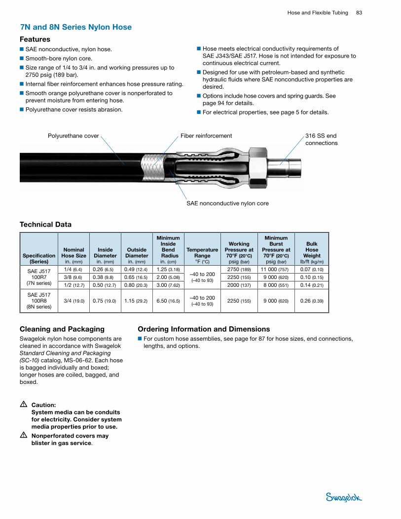
Hose and Flexible Tubing 83 HOSE /
FLEXIBLE TUBING
7N and 8N Series Nylon Hose
■SAE nonconductive, nylon hose.
■Smooth-bore nylon core.
■Size range of 1/4 to 3/4 in. and working pressures up to 2750 psig (189 bar).
■Internal fiber reinforcement enhances hose pressure rating.
■Smooth orange polyurethane cover is nonperforated to prevent moisture from entering hose.
■Polyurethane cover resists abrasion.
■Hose meets electrical conductivity requirements of SAE J343/SAE J517. Hose is not intended for exposure to continuous electrical current.
■Designed for use with petroleum-based and synthetic hydraulic fluids where SAE nonconductive properties are desired.
■Options include hose covers and spring guards. See page 94 for details.
■For electrical properties, see page 5 for details.
Features
Technical Data
Specification (Series)
Nominal Hose Size
in. (mm)
Inside Diameter in. (mm)
Outside Diameter in. (mm)
Minimum Inside Bend
Radius in. (cm)
Temperature Range °F (°C)
Working Pressure at 70°F (20°C) psig (bar)
Minimum Burst
Pressure at 70°F (20°C) psig (bar)
Bulk Hose
Weight lb/ft (kg/m)
SAE J517 100R7
(7N series)
1/4 (6.4) 0.26 (6.5) 0.49 (12.4) 1.25 (3.18) –40 to 200 (–40 to 93)
2750 (189) 11 000 (757) 0.07 (0.10)
3/8 (9.6) 0.38 (9.8) 0.65 (16.5) 2.00 (5.08) 2250 (155) 9 000 (620) 0.10 (0.15)
1/2 (12.7) 0.50 (12.7) 0.80 (20.3) 3.00 (7.62) 2000 (137) 8 000 (551) 0.14 (0.21)
SAE J517 100R8
(8N series)3/4 (19.0) 0.75 (19.0) 1.15 (29.2) 6.50 (16.5)
–40 to 200 (–40 to 93) 2250 (155) 9 000 (620) 0.26 (0.39)
• Caution: System media can be conduits for electricity. Consider system media properties prior to use.
• Nonperforated covers may blister in gas service.
Cleaning and PackagingSwagelok nylon hose components are cleaned in accordance with Swagelok Standard Cleaning and Packaging (SC‑10) catalog, MS-06-62. Each hose is bagged individually and boxed; longer hoses are coiled, bagged, and boxed.
Ordering Information and Dimensions■For custom hose assemblies, see page for 87 for hose sizes, end connections,
lengths, and options.
Fiber reinforcementPolyurethane cover
SAE nonconductive nylon core
316 SS end connections
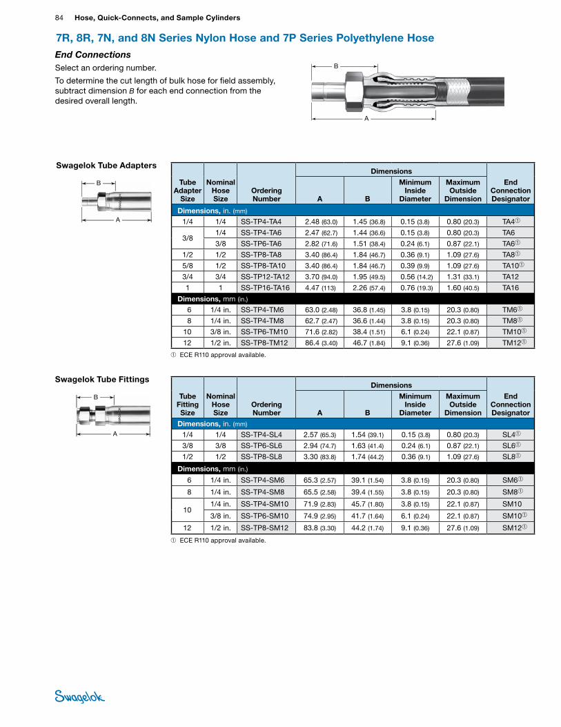
84 Hose, Quick-Connects, and Sample CylindersHO
SE /
FLEX
IBLE
TU
BING
End ConnectionsSelect an ordering number.
To determine the cut length of bulk hose for field assembly, subtract dimension B for each end connection from the desired overall length.
A
B
7R, 8R, 7N, and 8N Series Nylon Hose and 7P Series Polyethylene Hose
Swagelok Tube Adapters
Tube Adapter
Size
Nominal Hose Size
Ordering Number
Dimensions
End Connection DesignatorA B
Minimum Inside
Diameter
Maximum Outside
Dimension
Dimensions, in. (mm) 1/4 1/4 SS-TP4-TA4 2.48 (63.0) 1.45 (36.8) 0.15 (3.8) 0.80 (20.3) TA4➀
3/8 1/4 SS-TP4-TA6 2.47 (62.7) 1.44 (36.6) 0.15 (3.8) 0.80 (20.3) TA6
3/8 SS-TP6-TA6 2.82 (71.6) 1.51 (38.4) 0.24 (6.1) 0.87 (22.1) TA6➀
1/2 1/2 SS-TP8-TA8 3.40 (86.4) 1.84 (46.7) 0.36 (9.1) 1.09 (27.6) TA8➀
5/8 1/2 SS-TP8-TA10 3.40 (86.4) 1.84 (46.7) 0.39 (9.9) 1.09 (27.6) TA10➀
3/4 3/4 SS-TP12-TA12 3.70 (94.0) 1.95 (49.5) 0.56 (14.2) 1.31 (33.1) TA12
1 1 SS-TP16-TA16 4.47 (113) 2.26 (57.4) 0.76 (19.3) 1.60 (40.5) TA16
Dimensions, mm (in.) 6 1/4 in. SS-TP4-TM6 63.0 (2.48) 36.8 (1.45) 3.8 (0.15) 20.3 (0.80) TM6➀
8 1/4 in. SS-TP4-TM8 62.7 (2.47) 36.6 (1.44) 3.8 (0.15) 20.3 (0.80) TM8➀
10 3/8 in. SS-TP6-TM10 71.6 (2.82) 38.4 (1.51) 6.1 (0.24) 22.1 (0.87) TM10➀
12 1/2 in. SS-TP8-TM12 86.4 (3.40) 46.7 (1.84) 9.1 (0.36) 27.6 (1.09) TM12➀
A
B
Swagelok Tube Fittings
Tube Fitting Size
Nominal Hose Size
Ordering Number
Dimensions
End Connection DesignatorA B
Minimum Inside
Diameter
Maximum Outside
Dimension
Dimensions, in. (mm) 1/4 1/4 SS-TP4-SL4 2.57 (65.3) 1.54 (39.1) 0.15 (3.8) 0.80 (20.3) SL4➀
3/8 3/8 SS-TP6-SL6 2.94 (74.7) 1.63 (41.4) 0.24 (6.1) 0.87 (22.1) SL6➀
1/2 1/2 SS-TP8-SL8 3.30 (83.8) 1.74 (44.2) 0.36 (9.1) 1.09 (27.6) SL8➀
Dimensions, mm (in.)
6 1/4 in. SS-TP4-SM6 65.3 (2.57) 39.1 (1.54) 3.8 (0.15) 20.3 (0.80) SM6➀
8 1/4 in. SS-TP4-SM8 65.5 (2.58) 39.4 (1.55) 3.8 (0.15) 20.3 (0.80) SM8➀
10 1/4 in. SS-TP4-SM10 71.9 (2.83) 45.7 (1.80) 3.8 (0.15) 22.1 (0.87) SM10
3/8 in. SS-TP6-SM10 74.9 (2.95) 41.7 (1.64) 6.1 (0.24) 22.1 (0.87) SM10➀
12 1/2 in. SS-TP8-SM12 83.8 (3.30) 44.2 (1.74) 9.1 (0.36) 27.6 (1.09) SM12➀
A
B
➀ ECE R110 approval available.
➀ ECE R110 approval available.
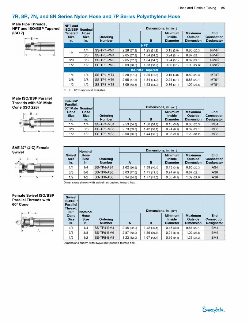
Hose and Flexible Tubing 85 HOSE /
FLEXIBLE TUBING
7R, 8R, 7N, and 8N Series Nylon Hose and 7P Series Polyethylene Hose Male Pipe Threads, NPT and ISO/BSP Tapered (ISO 7)
NPT and ISO/BSP Tapered
Size in.
Nominal Hose Sizein.
Ordering Number
Dimensions, in. (mm)
End Connection DesignatorA B
Minimum Inside
Diameter
Maximum Outside
Dimension
NPT
1/4 1/4 SS-TP4-PM4 2.28 (57.9) 1.25 (31.8) 0.15 (3.8) 0.80 (20.3) PM4➀
3/8 SS-TP6-PM4 2.65 (67.3) 1.34 (34.0) 0.24 (6.1) 0.87 (22.1) PM4➀
3/8 3/8 SS-TP6-PM6 2.65 (67.3) 1.34 (34.0) 0.24 (6.1) 0.87 (22.1) PM6➀
1/2 1/2 SS-TP8-PM8 3.09 (78.5) 1.53 (38.9) 0.36 (9.1) 1.09 (27.6) PM8➀
ISO/BSP Tapered 1/4 1/4 SS-TP4-MT4 2.28 (57.9) 1.25 (31.8) 0.15 (3.8) 0.80 (20.3) MT4➀
3/8 3/8 SS-TP6-MT6 2.65 (67.3) 1.34 (34.0) 0.24 (6.1) 0.87 (22.1) MT6➀
1/2 1/2 SS-TP8-MT8 3.09 (78.5) 1.53 (38.9) 0.36 (9.1) 1.09 (27.6) MT8➀
A
B
A
B
ISO/BSP Parallel, 60° Male
Cone Size in.
Nominal Hose Sizein.
Ordering Number
Dimensions, in. (mm)
End Connection DesignatorA B
Minimum Inside
Diameter
Maximum Outside
Dimension1/4 1/4 SS-TP4-MS4 2.53 (64.3) 1.50 (38.1) 0.15 (3.8) 0.80 (20.3) MS4
3/8 3/8 SS-TP6-MS6 2.73 (69.3) 1.42 (36.1) 0.24 (6.1) 0.87 (22.1) MS6
1/2 1/2 SS-TP8-MS8 3.00 (76.2) 1.44 (36.6) 0.36 (9.1) 1.23 (31.2) MS8
Male ISO/BSP Parallel Threads with 60° Male Cone (ISO 228)
Dimensions shown with swivel nut pushed toward hex.
Female Swivel ISO/BSP Parallel Threads with 60° Cone
Swivel ISO/BSP Parallel Thread,
60° Cone Size in.
Nominal Hose Sizein.
Ordering Number
Dimensions, in. (mm)
End Connection DesignatorA B
Minimum Inside
Diameter
Maximum Outside
Dimension1/4 1/4 SS-TP4-BM4 2.45 (62.2) 1.42 (36.1) 0.15 (3.8) 0.87 (22.1) BM4
3/8 3/8 SS-TP6-BM6 2.87 (72.9) 1.56 (39.6) 0.24 (6.1) 1.02 (25.8) BM6
1/2 1/2 SS-TP8-BM8 3.23 (82.0) 1.67 (42.4) 0.36 (9.1) 1.23 (31.2) BM8
A
B
SAE 37° (JIC) Female Swivel
Dimensions shown with swivel nut pushed toward hex.
Swivel Size in.
Nominal Hose Sizein.
Ordering Number
Dimensions, in. (mm)
End Connection DesignatorA B
Minimum Inside
Diameter
Maximum Outside
Dimension1/4 1/4 SS-TP4-AS4 2.62 (66.6) 1.59 (40.4) 0.15 (3.8) 0.80 (20.3) AS4
3/8 3/8 SS-TP6-AS6 3.03 (77.0) 1.71 (43.4) 0.24 (6.1) 0.87 (22.1) AS6
1/2 1/2 SS-TP8-AS8 3.34 (84.8) 1.77 (45.0) 0.36 (9.1) 1.09 (27.6) AS8 A
B
➀ ECE R110 approval available.
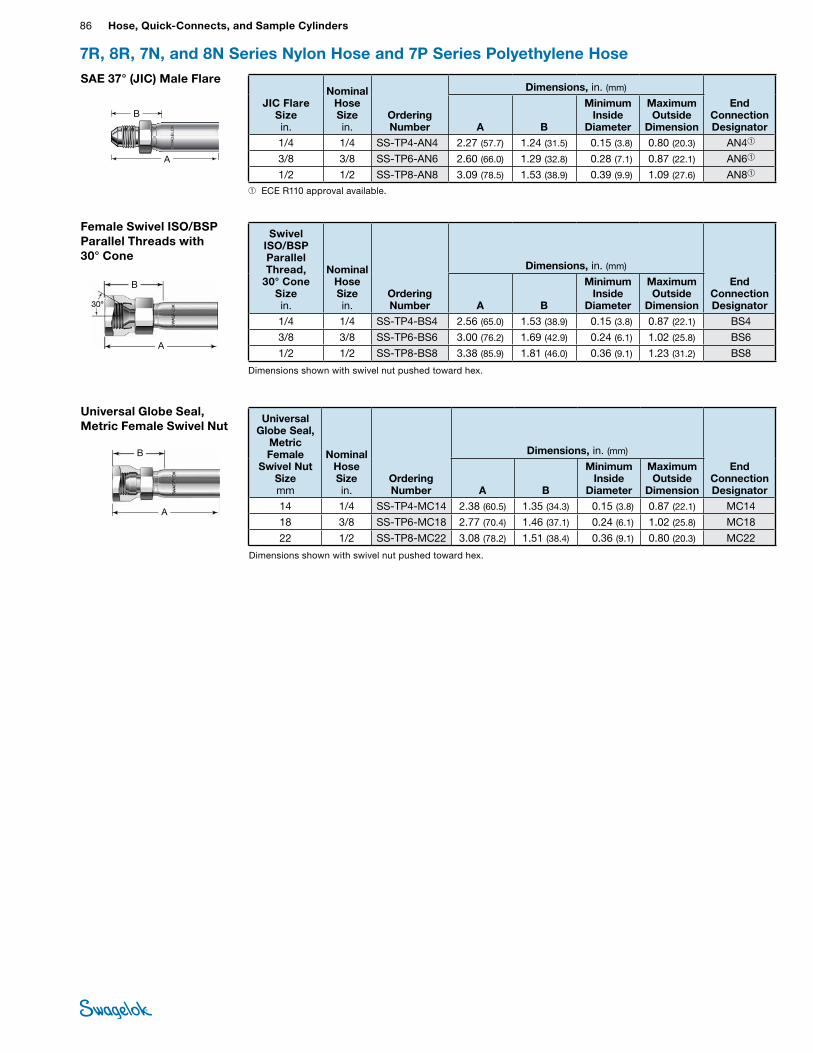
86 Hose, Quick-Connects, and Sample CylindersHO
SE /
FLEX
IBLE
TU
BING
7R, 8R, 7N, and 8N Series Nylon Hose and 7P Series Polyethylene Hose
Female Swivel ISO/BSP Parallel Threads with 30° Cone
Dimensions shown with swivel nut pushed toward hex.
Swivel ISO/BSP Parallel Thread,
30° Cone Size in.
Nominal Hose Sizein.
Ordering Number
Dimensions, in. (mm)
End Connection DesignatorA B
Minimum Inside
Diameter
Maximum Outside
Dimension1/4 1/4 SS-TP4-BS4 2.56 (65.0) 1.53 (38.9) 0.15 (3.8) 0.87 (22.1) BS4
3/8 3/8 SS-TP6-BS6 3.00 (76.2) 1.69 (42.9) 0.24 (6.1) 1.02 (25.8) BS6
1/2 1/2 SS-TP8-BS8 3.38 (85.9) 1.81 (46.0) 0.36 (9.1) 1.23 (31.2) BS8 A
B
Universal Globe Seal, Metric Female Swivel Nut
Dimensions shown with swivel nut pushed toward hex.
Universal Globe Seal,
Metric Female
Swivel Nut Size mm
Nominal Hose Sizein.
Ordering Number
Dimensions, in. (mm)
End Connection DesignatorA B
Minimum Inside
Diameter
Maximum Outside
Dimension14 1/4 SS-TP4-MC14 2.38 (60.5) 1.35 (34.3) 0.15 (3.8) 0.87 (22.1) MC14
18 3/8 SS-TP6-MC18 2.77 (70.4) 1.46 (37.1) 0.24 (6.1) 1.02 (25.8) MC18
22 1/2 SS-TP8-MC22 3.08 (78.2) 1.51 (38.4) 0.36 (9.1) 0.80 (20.3) MC22
A
B
SAE 37° (JIC) Male Flare
➀ ECE R110 approval available.
JIC Flare Size in.
Nominal Hose Sizein.
Ordering Number
Dimensions, in. (mm)
End Connection DesignatorA B
Minimum Inside
Diameter
Maximum Outside
Dimension1/4 1/4 SS-TP4-AN4 2.27 (57.7) 1.24 (31.5) 0.15 (3.8) 0.80 (20.3) AN4➀
3/8 3/8 SS-TP6-AN6 2.60 (66.0) 1.29 (32.8) 0.28 (7.1) 0.87 (22.1) AN6➀
1/2 1/2 SS-TP8-AN8 3.09 (78.5) 1.53 (38.9) 0.39 (9.9) 1.09 (27.6) AN8➀A
B
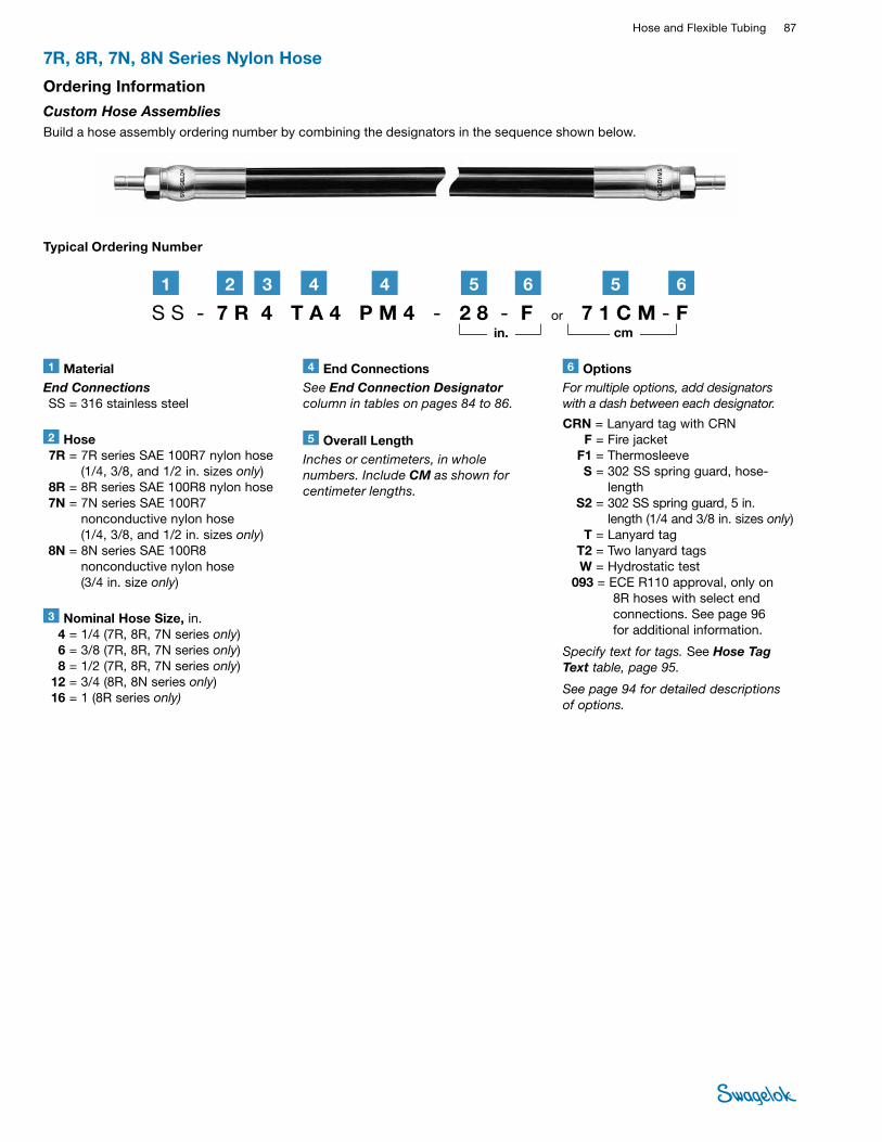
Hose and Flexible Tubing 87 HOSE /
FLEXIBLE TUBING
7R, 8R, 7N, 8N Series Nylon Hose
1 MaterialEnd Connections SS = 316 stainless steel
2 Hose 7R = 7R series SAE 100R7 nylon hose
(1/4, 3/8, and 1/2 in. sizes only) 8R = 8R series SAE 100R8 nylon hose 7N = 7N series SAE 100R7
nonconductive nylon hose (1/4, 3/8, and 1/2 in. sizes only)
8N = 8N series SAE 100R8 nonconductive nylon hose (3/4 in. size only)
6 OptionsFor multiple options, add designators with a dash between each designator.
CRN = Lanyard tag with CRN F = Fire jacket F1 = Thermosleeve S = 302 SS spring guard, hose-
length S2 = 302 SS spring guard, 5 in.
length (1/4 and 3/8 in. sizes only) T = Lanyard tag T2 = Two lanyard tags W = Hydrostatic test 093 = ECE R110 approval, only on
8R hoses with select end connections. See page 96 for additional information.
Specify text for tags. See Hose Tag Text table, page 95.
See page 94 for detailed descriptions of options.
3 Nominal Hose Size, in. 4 = 1/4 (7R, 8R, 7N series only) 6 = 3/8 (7R, 8R, 7N series only) 8 = 1/2 (7R, 8R, 7N series only) 12 = 3/4 (8R, 8N series only) 16 = 1 (8R series only)
Typical Ordering Number
5 Overall LengthInches or centimeters, in whole numbers. Include CM as shown for centimeter lengths.
S S - 7 R 4 T A 4 P M 4 - 2 8 - F or 7 1 C M - F21 3
in. cm
Ordering Information
Custom Hose Assemblies Build a hose assembly ordering number by combining the designators in the sequence shown below.
644 5
4 End ConnectionsSee End Connection Designator column in tables on pages 84 to 86.
65
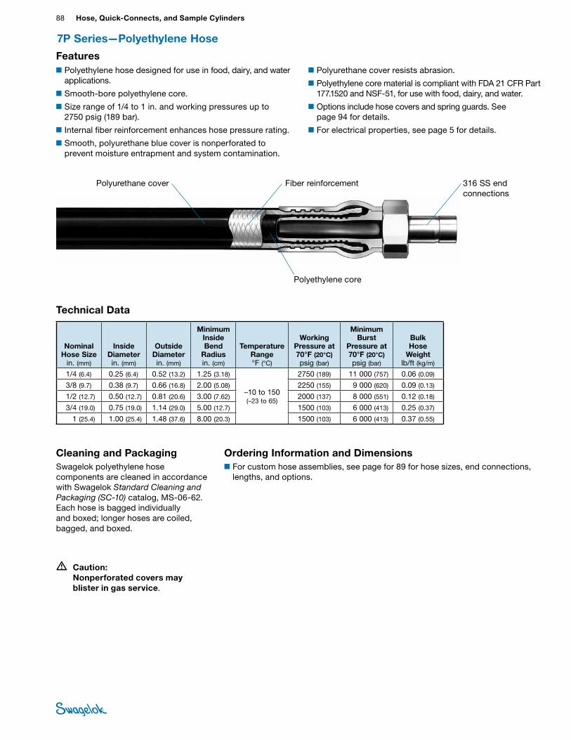
88 Hose, Quick-Connects, and Sample CylindersHO
SE /
FLEX
IBLE
TU
BING
7P Series—Polyethylene Hose
Features
Technical Data
Nominal Hose Size
in. (mm)
Inside Diameter in. (mm)
Outside Diameter in. (mm)
Minimum Inside Bend
Radius in. (cm)
Temperature Range °F (°C)
Working Pressure at 70°F (20°C) psig (bar)
Minimum Burst
Pressure at 70°F (20°C) psig (bar)
Bulk Hose
Weight lb/ft (kg/m)
1/4 (6.4) 0.25 (6.4) 0.52 (13.2) 1.25 (3.18)
–10 to 150 (–23 to 65)
2750 (189) 11 000 (757) 0.06 (0.09)
3/8 (9.7) 0.38 (9.7) 0.66 (16.8) 2.00 (5.08) 2250 (155) 9 000 (620) 0.09 (0.13)
1/2 (12.7) 0.50 (12.7) 0.81 (20.6) 3.00 (7.62) 2000 (137) 8 000 (551) 0.12 (0.18)
3/4 (19.0) 0.75 (19.0) 1.14 (29.0) 5.00 (12.7) 1500 (103) 6 000 (413) 0.25 (0.37)
1 (25.4) 1.00 (25.4) 1.48 (37.6) 8.00 (20.3) 1500 (103) 6 000 (413) 0.37 (0.55)
• Caution: Nonperforated covers may blister in gas service.
Cleaning and PackagingSwagelok polyethylene hose components are cleaned in accordance with Swagelok Standard Cleaning and Packaging (SC‑10) catalog, MS-06-62. Each hose is bagged individually and boxed; longer hoses are coiled, bagged, and boxed.
Ordering Information and Dimensions■For custom hose assemblies, see page for 89 for hose sizes, end connections,
lengths, and options.
Fiber reinforcementPolyurethane cover
Polyethylene core
316 SS end connections
■Polyethylene hose designed for use in food, dairy, and water applications.
■Smooth-bore polyethylene core.
■Size range of 1/4 to 1 in. and working pressures up to 2750 psig (189 bar).
■Internal fiber reinforcement enhances hose pressure rating.
■Smooth, polyurethane blue cover is nonperforated to prevent moisture entrapment and system contamination.
■Polyurethane cover resists abrasion.
■Polyethylene core material is compliant with FDA 21 CFR Part 177.1520 and NSF-51, for use with food, dairy, and water.
■Options include hose covers and spring guards. See page 94 for details.
■For electrical properties, see page 5 for details.
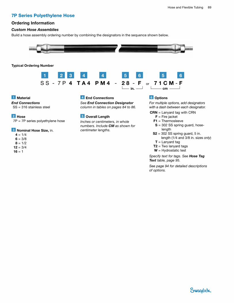
Hose and Flexible Tubing 89 HOSE /
FLEXIBLE TUBING
7P Series Polyethylene Hose
1 MaterialEnd Connections SS = 316 stainless steel
2 Hose 7P = 7P series polyethylene hose
6 OptionsFor multiple options, add designators with a dash between each designator.
CRN = Lanyard tag with CRN F = Fire jacket F1 = Thermosleeve S = 302 SS spring guard, hose-
length S2 = 302 SS spring guard, 5 in.
length (1/4 and 3/8 in. sizes only) T = Lanyard tag T2 = Two lanyard tags W = Hydrostatic test
Specify text for tags. See Hose Tag Text table, page 95.
See page 94 for detailed descriptions of options.
3 Nominal Hose Size, in. 4 = 1/4 6 = 3/8 8 = 1/2 12 = 3/4 16 = 1
5 Overall LengthInches or centimeters, in whole numbers. Include CM as shown for centimeter lengths.
S S - 7 P 4 T A 4 P M 4 - 2 8 - F or 7 1 C M - F2 61 3 44 5
in. cm
Typical Ordering Number
Ordering Information
Custom Hose Assemblies Build a hose assembly ordering number by combining the designators in the sequence shown below.
4 End ConnectionsSee End Connection Designator column in tables on pages 84 to 86.
65
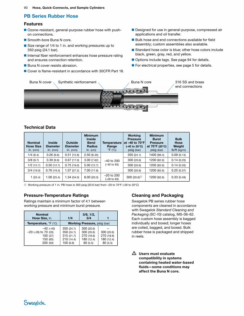
90 Hose, Quick-Connects, and Sample CylindersHO
SE /
FLEX
IBLE
TU
BING
Synthetic reinforcementBuna N cover Buna N c ore
Technical Data
PB Series Rubber Hose
■Ozone-resistant, general-purpose rubber hose with push-on connections.
■Smooth-bore Buna N core.
■Size range of 1/4 to 1 in. and working pressures up to 350 psig (24.1 bar).
■Internal fiber reinforcement enhances hose pressure rating and ensures connection retention.
■Buna N cover resists abrasion.
■Cover is flame-resistant in accordance with 30CFR Part 18.
■Designed for use in general-purpose, compressed air applications and oil transfer.
■Bulk hose and end connections available for field assembly; custom assemblies also available.
■Standard hose color is blue; other hose colors include black, green, gray, red, and yellow.
■Options include tags. See page 94 for details.
■For electrical properties, see page 5 for details.
Cleaning and PackagingSwagelok PB series rubber hose components are cleaned in accordance with Swagelok Standard Cleaning and Packaging (SC‑10) catalog, MS-06-62. Each custom hose assembly is bagged individually and boxed; longer hoses are coiled, bagged, and boxed. Bulk rubber hose is packaged and shipped in reels.
Pressure-Temperature RatingsRatings maintain a minimum factor of 4:1 between working pressure and minimum burst pressure.
Nominal Hose Size
in. (mm)
Inside Diameter in. (mm)
Outside Diameter in. (mm)
Minimum Inside Bend
Radius in. (cm)
Temperature Range °F (°C)
Working Pressure
at –40 to 70°F (–40 to 20°C)
psig (bar)
Minimum Burst
Pressure at 70°F (20°C)
psig (bar)
Bulk Hose
Weight lb/ft (kg/m)
1/4 (6.4) 0.26 (6.6) 0.51 (12.8) 2.50 (6.35)
–40 to 200 (–40 to 93)
350 (24.1) 1400 (96.4) 0.09 (0.13)
3/8 (9.7) 0.39 (9.9) 0.67 (17.0) 3.00 (7.62) 300 (20.6) 1200 (82.6) 0.14 (0.20)
1/2 (12.7) 0.50 (12.7) 0.75 (19.0) 5.00 (12.7) 300 (20.6) 1200 (82.6) 0.14 (0.20)
3/4 (19.0) 0.76 (19.3) 1.07 (27.2) 7.00 (17.8) 300 (20.6) 1200 (82.6) 0.25 (0.37)
1 (25.4) 1.00 (25.4) 1.34 (34.0) 8.00 (20.3)–20 to 200 (–28 to 93)
300 (20.6)➀ 1200 (82.6) 0.33 (0.49)
Nominal Hose Size, in. 1/4
3/8, 1/2, 3/4 1
Temperature, °F (°C) Working Pressure, psig (bar)
–40 (–40) –20 (–28) to 70 (20) 100 (37) 150 (65) 200 (93)
350 (24.1)350 (24.1) 315 (21.7) 210 (14.4) 100 (6.8)
300 (20.6) 300 (20.6) 270 (18.6) 180 (12.4) 80 (5.5)
—300 (20.6) 270 (18.6) 180 (12.4) 80 (5.5)
Features
316 SS and brass end connections
• Users must evaluate compatibility in systems containing heated water-based fluids—some conditions may affect the Buna N core.
➀ Working pressure of 1 in. PB hose is 300 psig (20.6 bar) from –20 to 70°F (-28 to 20°C)
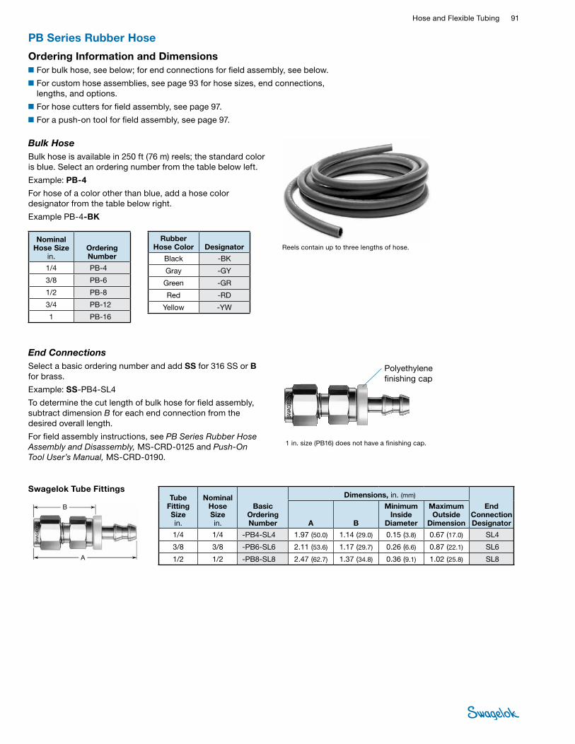
Hose and Flexible Tubing 91 HOSE /
FLEXIBLE TUBING
End ConnectionsSelect a basic ordering number and add SS for 316 SS or B for brass.
Example: SS-PB4-SL4
To determine the cut length of bulk hose for field assembly, subtract dimension B for each end connection from the desired overall length.
For field assembly instructions, see PB Series Rubber Hose Assembly and Disassembly, MS-CRD-0125 and Push‑On Tool User’s Manual, MS-CRD-0190.
A
B
Swagelok Tube FittingsTube
Fitting Size in.
Nominal Hose Size in.
Basic Ordering Number
Dimensions, in. (mm)
End Connection DesignatorA B
Minimum Inside
Diameter
Maximum Outside
Dimension
1/4 1/4 -PB4-SL4 1.97 (50.0) 1.14 (29.0) 0.15 (3.8) 0.67 (17.0) SL4
3/8 3/8 -PB6-SL6 2.11 (53.6) 1.17 (29.7) 0.26 (6.6) 0.87 (22.1) SL6
1/2 1/2 -PB8-SL8 2.47 (62.7) 1.37 (34.8) 0.36 (9.1) 1.02 (25.8) SL8
Polyethylene finishing cap
PB Series Rubber Hose
Bulk HoseBulk hose is available in 250 ft (76 m) reels; the standard color is blue. Select an ordering number from the table below left.
Example: PB-4
For hose of a color other than blue, add a hose color designator from the table below right.
Example PB-4-BK
Reels contain up to three lengths of hose.Nominal
Hose Size in.
Ordering Number
1/4 PB-4
3/8 PB-6
1/2 PB-8
3/4 PB-12
1 PB-16
Rubber Hose Color Designator
Black -BK
Gray -GY
Green -GR
Red -RD
Yellow -YW
Ordering Information and Dimensions■For bulk hose, see below; for end connections for field assembly, see below.
■For custom hose assemblies, see page 93 for hose sizes, end connections, lengths, and options.
■For hose cutters for field assembly, see page 97.
■For a push-on tool for field assembly, see page 97.
1 in. size (PB16) does not have a finishing cap.
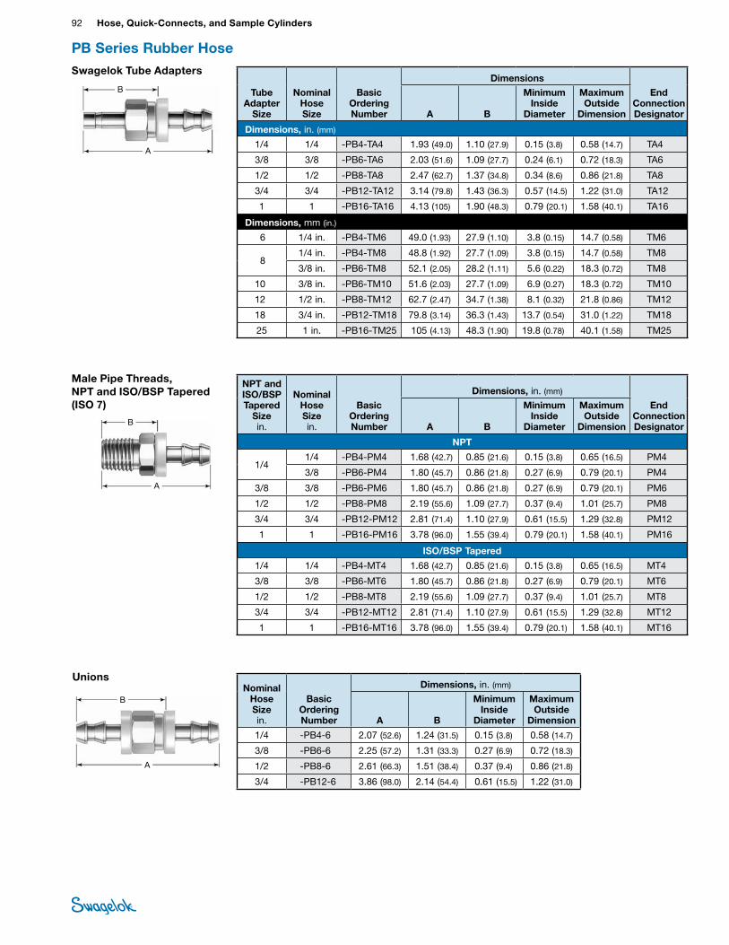
92 Hose, Quick-Connects, and Sample CylindersHO
SE /
FLEX
IBLE
TU
BING
PB Series Rubber Hose
UnionsNominal
Hose Size in.
Basic Ordering Number
Dimensions, in. (mm)
A B
Minimum Inside
Diameter
Maximum Outside
Dimension
1/4 -PB4-6 2.07 (52.6) 1.24 (31.5) 0.15 (3.8) 0.58 (14.7)
3/8 -PB6-6 2.25 (57.2) 1.31 (33.3) 0.27 (6.9) 0.72 (18.3)
1/2 -PB8-6 2.61 (66.3) 1.51 (38.4) 0.37 (9.4) 0.86 (21.8)
3/4 -PB12-6 3.86 (98.0) 2.14 (54.4) 0.61 (15.5) 1.22 (31.0)
A
B
Swagelok Tube Adapters
Tube Adapter
Size
Nominal Hose Size
Basic Ordering Number
Dimensions
End Connection DesignatorA B
Minimum Inside
Diameter
Maximum Outside
Dimension
Dimensions, in. (mm)
1/4 1/4 -PB4-TA4 1.93 (49.0) 1.10 (27.9) 0.15 (3.8) 0.58 (14.7) TA4
3/8 3/8 -PB6-TA6 2.03 (51.6) 1.09 (27.7) 0.24 (6.1) 0.72 (18.3) TA6
1/2 1/2 -PB8-TA8 2.47 (62.7) 1.37 (34.8) 0.34 (8.6) 0.86 (21.8) TA8
3/4 3/4 -PB12-TA12 3.14 (79.8) 1.43 (36.3) 0.57 (14.5) 1.22 (31.0) TA12
1 1 -PB16-TA16 4.13 (105) 1.90 (48.3) 0.79 (20.1) 1.58 (40.1) TA16
Dimensions, mm (in.)
6 1/4 in. -PB4-TM6 49.0 (1.93) 27.9 (1.10) 3.8 (0.15) 14.7 (0.58) TM6
8 1/4 in. -PB4-TM8 48.8 (1.92) 27.7 (1.09) 3.8 (0.15) 14.7 (0.58) TM8
3/8 in. -PB6-TM8 52.1 (2.05) 28.2 (1.11) 5.6 (0.22) 18.3 (0.72) TM8
10 3/8 in. -PB6-TM10 51.6 (2.03) 27.7 (1.09) 6.9 (0.27) 18.3 (0.72) TM10
12 1/2 in. -PB8-TM12 62.7 (2.47) 34.7 (1.38) 8.1 (0.32) 21.8 (0.86) TM12
18 3/4 in. -PB12-TM18 79.8 (3.14) 36.3 (1.43) 13.7 (0.54) 31.0 (1.22) TM18
25 1 in. -PB16-TM25 105 (4.13) 48.3 (1.90) 19.8 (0.78) 40.1 (1.58) TM25
A
B
Male Pipe Threads, NPT and ISO/BSP Tapered (ISO 7)
NPT and ISO/BSP Tapered
Sizein.
Nominal Hose Size in.
Basic Ordering Number
Dimensions, in. (mm)
End Connection DesignatorA B
Minimum Inside
Diameter
Maximum Outside
Dimension
NPT
1/41/4 -PB4-PM4 1.68 (42.7) 0.85 (21.6) 0.15 (3.8) 0.65 (16.5) PM4
3/8 -PB6-PM4 1.80 (45.7) 0.86 (21.8) 0.27 (6.9) 0.79 (20.1) PM4
3/8 3/8 -PB6-PM6 1.80 (45.7) 0.86 (21.8) 0.27 (6.9) 0.79 (20.1) PM6
1/2 1/2 -PB8-PM8 2.19 (55.6) 1.09 (27.7) 0.37 (9.4) 1.01 (25.7) PM8
3/4 3/4 -PB12-PM12 2.81 (71.4) 1.10 (27.9) 0.61 (15.5) 1.29 (32.8) PM12
1 1 -PB16-PM16 3.78 (96.0) 1.55 (39.4) 0.79 (20.1) 1.58 (40.1) PM16
ISO/BSP Tapered
1/4 1/4 -PB4-MT4 1.68 (42.7) 0.85 (21.6) 0.15 (3.8) 0.65 (16.5) MT4
3/8 3/8 -PB6-MT6 1.80 (45.7) 0.86 (21.8) 0.27 (6.9) 0.79 (20.1) MT6
1/2 1/2 -PB8-MT8 2.19 (55.6) 1.09 (27.7) 0.37 (9.4) 1.01 (25.7) MT8
3/4 3/4 -PB12-MT12 2.81 (71.4) 1.10 (27.9) 0.61 (15.5) 1.29 (32.8) MT12
1 1 -PB16-MT16 3.78 (96.0) 1.55 (39.4) 0.79 (20.1) 1.58 (40.1) MT16
A
B
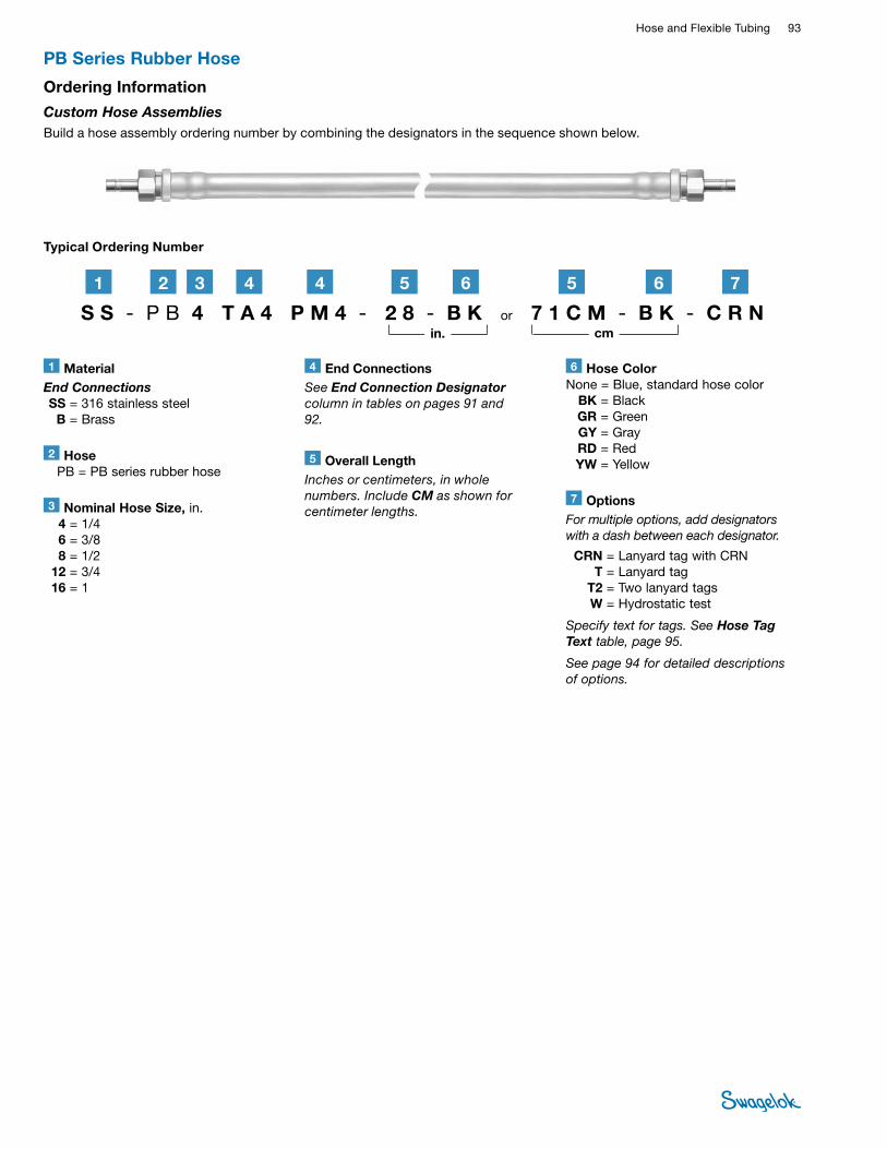
Hose and Flexible Tubing 93 HOSE /
FLEXIBLE TUBING
1 MaterialEnd Connections SS = 316 stainless steel B = Brass
2 Hose PB = PB series rubber hose
6 Hose Color None = Blue, standard hose color BK = Black GR = Green GY = Gray RD = Red YW = Yellow
3 Nominal Hose Size, in. 4 = 1/4 6 = 3/8 8 = 1/2 12 = 3/4 16 = 1
5 Overall LengthInches or centimeters, in whole numbers. Include CM as shown for centimeter lengths.
Typical Ordering Number
Ordering Information
Custom Hose Assemblies Build a hose assembly ordering number by combining the designators in the sequence shown below.
S S - P B 4 T A 4 P M 4 - 2 8 - B K or 7 1 C M - B K - C R N
2 61 3 44 5
in. cm
765
4 End ConnectionsSee End Connection Designator column in tables on pages 91 and 92.
PB Series Rubber Hose
7 OptionsFor multiple options, add designators with a dash between each designator.
CRN = Lanyard tag with CRN T = Lanyard tag T2 = Two lanyard tags W = Hydrostatic test
Specify text for tags. See Hose Tag Text table, page 95.
See page 94 for detailed descriptions of options.
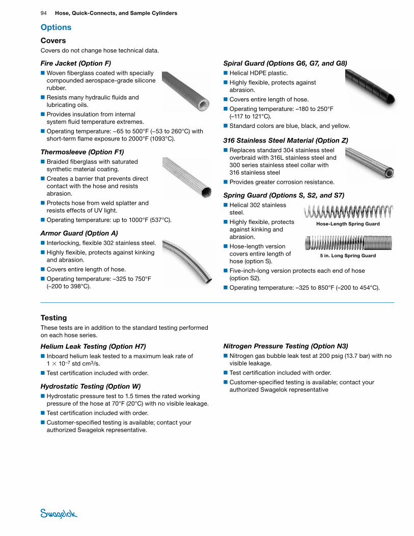
94 Hose, Quick-Connects, and Sample CylindersHO
SE /
FLEX
IBLE
TU
BING
Spiral Guard (Options G6, G7, and G8)■Helical HDPE plastic.
■Highly flexible, protects against abrasion.
■Covers entire length of hose.
■Operating temperature: –180 to 250°F (–117 to 121°C).
■Standard colors are blue, black, and yellow.
316 Stainless Steel Material (Option Z)■Replaces standard 304 stainless steel
overbraid with 316L stainless steel and 300 series stainless steel collar with 316 stainless steel
■Provides greater corrosion resistance.
Spring Guard (Options S, S2, and S7)■Helical 302 stainless
steel.
■Highly flexible, protects against kinking and abrasion.
■Hose-length version covers entire length of hose (option S).
■Five-inch-long version protects each end of hose (option S2).
■Operating temperature: –325 to 850°F (–200 to 454°C).
5 in. Long Spring Guard
Hose-Length Spring Guard
Fire Jacket (Option F)■Woven fiberglass coated with specially
compounded aerospace-grade silicone rubber.
■Resists many hydraulic fluids and lubricating oils.
■Provides insulation from internal system fluid temperature extremes.
■Operating temperature: −65 to 500°F (−53 to 260°C) with short-term flame exposure to 2000°F (1093°C).
Thermosleeve (Option F1)■Braided fiberglass with saturated
synthetic material coating.
■Creates a barrier that prevents direct contact with the hose and resists abrasion.
■Protects hose from weld splatter and resists effects of UV light.
■Operating temperature: up to 1000°F (537°C).
Armor Guard (Option A)■Interlocking, flexible 302 stainless steel.
■Highly flexible, protects against kinking and abrasion.
■Covers entire length of hose.
■Operating temperature: –325 to 750°F (–200 to 398°C).
Options
CoversCovers do not change hose technical data.
TestingThese tests are in addition to the standard testing performed on each hose series.
Helium Leak Testing (Option H7)■Inboard helium leak tested to a maximum leak rate of
1 × 10⁻⁷ std cm3/s.
■Test certification included with order.
Hydrostatic Testing (Option W)■Hydrostatic pressure test to 1.5 times the rated working
pressure of the hose at 70°F (20°C) with no visible leakage.
■Test certification included with order.
■Customer-specified testing is available; contact your authorized Swagelok representative.
Nitrogen Pressure Testing (Option N3)■Nitrogen gas bubble leak test at 200 psig (13.7 bar) with no
visible leakage.
■Test certification included with order.
■Customer-specified testing is available; contact your authorized Swagelok representative
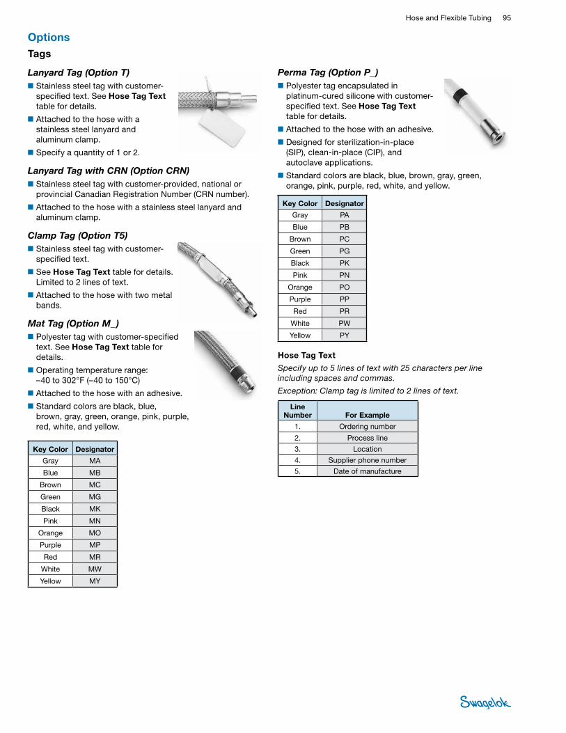
Hose and Flexible Tubing 95 HOSE /
FLEXIBLE TUBING
Perma Tag (Option P_ )■Polyester tag encapsulated in
platinum-cured silicone with customer-specified text. See Hose Tag Text table for details.
■ Attached to the hose with an adhesive.
■Designed for sterilization-in-place (SIP), clean-in-place (CIP), and autoclave applications.
■Standard colors are black, blue, brown, gray, green, orange, pink, purple, red, white, and yellow.
Hose Tag Text
Specify up to 5 lines of text with 25 characters per line including spaces and commas.
Exception: Clamp tag is limited to 2 lines of text.
Line Number For Example
1. Ordering number
2. Process line
3. Location
4. Supplier phone number
5. Date of manufacture
Key Color Designator
Gray PA
Blue PB
Brown PC
Green PG
Black PK
Pink PN
Orange PO
Purple PP
Red PR
White PW
Yellow PY
Tags
Lanyard Tag (Option T)■ Stainless steel tag with customer-
specified text. See Hose Tag Text table for details.
■ Attached to the hose with a stainless steel lanyard and aluminum clamp.
■ Specify a quantity of 1 or 2.
Lanyard Tag with CRN (Option CRN)■ Stainless steel tag with customer-provided, national or
provincial Canadian Registration Number (CRN number).
■ Attached to the hose with a stainless steel lanyard and aluminum clamp.
Clamp Tag (Option T5)■ Stainless steel tag with customer-
specified text.
■ See Hose Tag Text table for details. Limited to 2 lines of text.
■ Attached to the hose with two metal bands.
Mat Tag (Option M_ )■Polyester tag with customer-specified
text. See Hose Tag Text table for details.
■Operating temperature range: –40 to 302°F (–40 to 150°C)
■Attached to the hose with an adhesive.
■Standard colors are black, blue, brown, gray, green, orange, pink, purple, red, white, and yellow.
Options
Key Color Designator
Gray MA
Blue MB
Brown MC
Green MG
Black MK
Pink MN
Orange MO
Purple MP
Red MR
White MW
Yellow MY
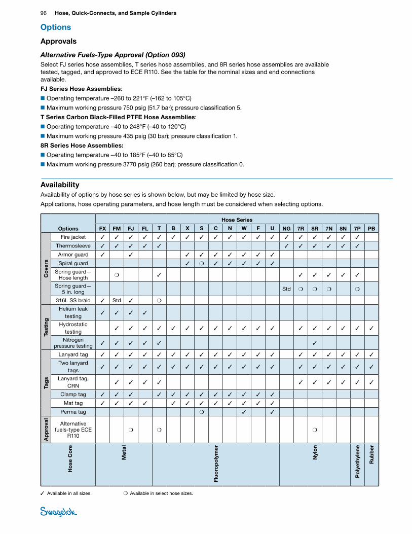
96 Hose, Quick-Connects, and Sample CylindersHO
SE /
FLEX
IBLE
TU
BING
Options
Hose Series
FX FM FJ FL T B X S C N W F U NG 7R 8R 7N 8N 7P PB
Co
vers
Fire jacket ✓ ✓ ✓ ✓ ✓ ✓ ✓ ✓ ✓ ✓ ✓ ✓ ✓ ✓ ✓ ✓ ✓ ✓ ✓
Thermosleeve ✓ ✓ ✓ ✓ ✓ ✓ ✓ ✓ ✓ ✓ ✓
Armor guard ✓ ✓ ✓ ✓ ✓ ✓ ✓ ✓ ✓
Spiral guard ✓ ❍ ✓ ✓ ✓ ✓ ✓
Spring guard— Hose length ❍ ✓ ✓ ✓ ✓ ✓ ✓
Spring guard— 5 in. long Std ❍ ❍ ❍ ❍
316L SS braid ✓ Std ✓ ❍
Test
ing
Helium leak testing
✓ ✓ ✓ ✓
Hydrostatic testing
✓ ✓ ✓ ✓ ✓ ✓ ✓ ✓ ✓ ✓ ✓ ✓ ✓ ✓ ✓ ✓ ✓ ✓
Nitrogen pressure testing ✓ ✓ ✓ ✓ ✓ ✓
Tag
s
Lanyard tag ✓ ✓ ✓ ✓ ✓ ✓ ✓ ✓ ✓ ✓ ✓ ✓ ✓ ✓ ✓ ✓ ✓ ✓ ✓
Two lanyard tags
✓ ✓ ✓ ✓ ✓ ✓ ✓ ✓ ✓ ✓ ✓ ✓ ✓ ✓ ✓ ✓ ✓ ✓ ✓
Lanyard tag, CRN
✓ ✓ ✓ ✓ ✓ ✓ ✓ ✓ ✓ ✓
Clamp tag ✓ ✓ ✓ ✓ ✓ ✓ ✓ ✓ ✓ ✓ ✓ ✓
Mat tag ✓ ✓ ✓ ✓ ✓ ✓ ✓ ✓ ✓ ✓ ✓ ✓
Perma tag ❍ ✓ ✓
Ap
pro
val
Alternative fuels-type ECE
R110❍ ❍ ❍
Ho
se C
ore
Met
al
Fluo
rop
oly
mer
Nyl
on
Po
lyet
hyle
ne
Rub
ber
AvailabilityAvailability of options by hose series is shown below, but may be limited by hose size.
Applications, hose operating parameters, and hose length must be considered when selecting options.
Options
✓ Available in all sizes. ❍ Available in select hose sizes.
Approvals
Alternative Fuels-Type Approval (Option 093)Select FJ series hose assemblies, T series hose assemblies, and 8R series hose assemblies are available tested, tagged, and approved to ECE R110. See the table for the nominal sizes and end connections available.
FJ Series Hose Assemblies:
■Operating temperature –260 to 221°F (–162 to 105°C)
■Maximum working pressure 750 psig (51.7 bar); pressure classification 5.
T Series Carbon Black-Filled PTFE Hose Assemblies:
■Operating temperature –40 to 248°F (–40 to 120°C)
■Maximum working pressure 435 psig (30 bar); pressure classification 1.
8R Series Hose Assemblies:
■Operating temperature –40 to 185°F (–40 to 85°C)
■Maximum working pressure 3770 psig (260 bar); pressure classification 0.
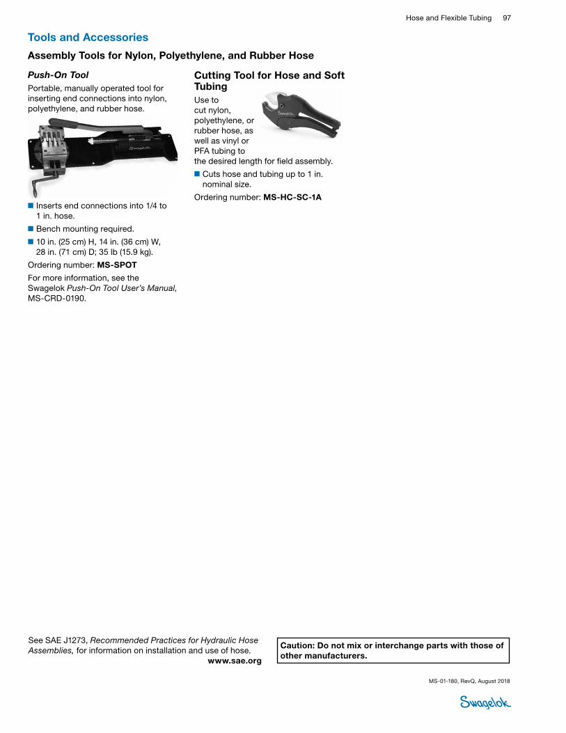
Hose and Flexible Tubing 97 HOSE /
FLEXIBLE TUBING
Assembly Tools for Nylon, Polyethylene, and Rubber Hose
Tools and Accessories
Push-On Tool Portable, manually operated tool for inserting end connections into nylon, polyethylene, and rubber hose.
■Inserts end connections into 1/4 to 1 in. hose.
■Bench mounting required.
■10 in. (25 cm) H, 14 in. (36 cm) W, 28 in. (71 cm) D; 35 lb (15.9 kg).
Ordering number: MS-SPOT
For more information, see the Swagelok Push‑On Tool User’s Manual, MS-CRD-0190.
Cutting Tool for Hose and Soft TubingUse to cut nylon, polyethylene, or rubber hose, as well as vinyl or PFA tubing to the desired length for field assembly.
■Cuts hose and tubing up to 1 in. nominal size.
Ordering number: MS-HC-SC-1A
Caution: Do not mix or interchange parts with those of other manufacturers.
MS-01-180, RevQ, August 2018
See SAE J1273, Recommended Practices for Hydraulic Hose Assemblies, for information on installation and use of hose. www.sae.org
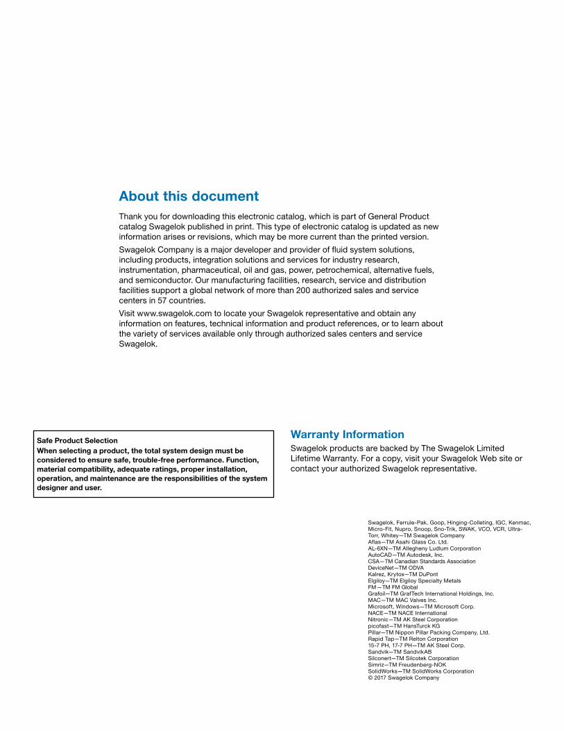
About this documentThank you for downloading this electronic catalog, which is part of General Product catalog Swagelok published in print. This type of electronic catalog is updated as new information arises or revisions, which may be more current than the printed version.
Swagelok Company is a major developer and provider of fluid system solutions, including products, integration solutions and services for industry research, instrumentation, pharmaceutical, oil and gas, power, petrochemical, alternative fuels, and semiconductor. Our manufacturing facilities, research, service and distribution facilities support a global network of more than 200 authorized sales and service centers in 57 countries.
Visit www.swagelok.com to locate your Swagelok representative and obtain any information on features, technical information and product references, or to learn about the variety of services available only through authorized sales centers and service Swagelok.
Safe Product SelectionWhen selecting a product, the total system design must be considered to ensure safe, trouble-free performance. Function, material compatibility, adequate ratings, proper installation, operation, and maintenance are the responsibilities of the system designer and user.
Warranty InformationSwagelok products are backed by The Swagelok Limited Lifetime Warranty. For a copy, visit your Swagelok Web site or contact your authorized Swagelok representative.
Swagelok, Ferrule-Pak, Goop, Hinging-Colleting, IGC, Kenmac, Micro-Fit, Nupro, Snoop, Sno-Trik, SWAK, VCO, VCR, Ultra-Torr, Whitey—TM Swagelok CompanyAflas—TM Asahi Glass Co. Ltd.AL-6XN—TM Allegheny Ludlum CorporationAutoCAD—TM Autodesk, Inc.CSA—TM Canadian Standards AssociationDeviceNet—TM ODVAKalrez, Krytox—TM DuPontElgiloy—TM Elgiloy Specialty Metals FM—TM FM GlobalGrafoil—TM GrafTech International Holdings, Inc.MAC—TM MAC Valves Inc.Microsoft, Windows—TM Microsoft Corp.NACE—TM NACE InternationalNitronic—TM AK Steel Corporationpicofast—TM HansTurck KGPillar—TM Nippon Pillar Packing Company, Ltd.Rapid Tap—TM Relton Corporation15-7 PH, 17-7 PH—TM AK Steel Corp.Sandvik—TM SandvikABSilconert—TM Silcotek CorporationSimriz—TM Freudenberg-NOKSolidWorks—TM SolidWorks Corporation© 2017 Swagelok Company