holographic cylindrical grating for euv spectroscopy in near normal incidence
TRANSCRIPT
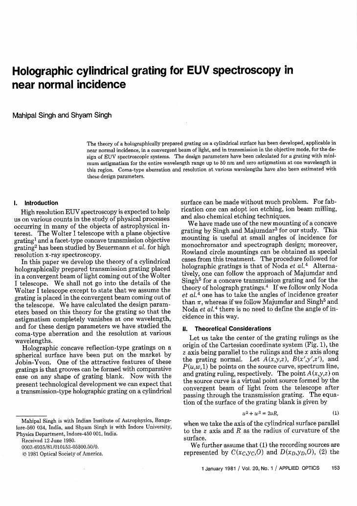
Holographic cylindrical grating for EUV spectroscopy innear normal incidence
Mahipal Singh and Shyam Singh
The theory of a holographically prepared grating on a cylindrical surface has been developed, applicable in
near normal incidence, in a convergent beam of light, and in transmission in the objective mode, for the de-
sign of EUV spectroscopic systems. The design parameters have been calculated for a grating with mini-
mum astigmatism for the entire wavelength range up to 50 nm and zero astigmatism at one wavelength inthis region. Coma-type aberration and resolution at various wavelengths have also been estimated withthese design parameters.
1. Introduction
High resolution EUV spectroscopy is expected to helpus on various counts in the study of physical processesoccurring in many of the objects of astrophysical in-terest. The Wolter I telescope with a plane objectivegrating' and a facet-type concave transmission objectivegrating2 has been studied by Beuermann et al. for highresolution x-ray spectroscopy.
In this paper we develop the theory of a cylindricalholographically prepared transmission grating placedin a convergent beam of light coming out of the WolterI telescope. We shall not go into the details of theWolter I telescope except to state that we assume thegrating is placed in the convergent beam coming out ofthe telescope. We have calculated the design param-eters based on this theory for the grating so that theastigmatism completely vanishes at one wavelength,and for these design parameters we have studied thecoma-type aberration and the resolution at variouswavelengths.
Holographic concave reflection-type gratings on aspherical surface have been put on the market byJobin-Yvon. One of the attractive features of thesegratings is that grooves can be formed with comparativeease on any shape of grating blank. Now with thepresent technological development we can expect thata transmission-type holographic grating on a cylindrical
Mahipal Singh is with Indian Institute of Astrophysics, Banga-lore-560 034, India, and Shyam Singh is with Indore University,Physics Department, Indore-450 001, India.
Received 12 June 1980.0003-6935/81/010153-05$00.50/0.(© 1981 Optical Society of America.
surface can be made without much problem. For fab-rication one can adopt ion etching, ion beam milling,and also chemical etching techniques.
We have made use of the new mounting of a concavegrating by Singh and Majumdar3 for our study. Thismounting is useful at small angles of incidence formonochromator and spectrograph design; moreover,Rowland circle mountings can be obtained as specialcases from this treatment. The procedure followed forholographic gratings is that of Noda et al.4 Alterna-tively, one can follow the approach of Majumdar andSingh5 for a concave transmission grating and for thetheory of holograph gratings. 4 If we follow only Nodaet al.4 one has to take the angles of incidence greaterthan 7r, whereas if we follow Majumdar and Singh5 andNoda et al.4 there is no need to define the angle of in-cidence in this way.
II. Theoretical Considerations
Let us take the center of the grating rulings as theorigin of the Cartesian coordinate system (Fig. 1), thez axis being parallel to the rulings and the x axis alongthe grating normal. Let A(x,y,z), B(x',y',z'), andP(u,w, 1) be points on the source curve, spectrum line,and grating ruling, respectively. The point A (x,y,z) onthe source curve is a virtual point source formed by theconvergent beam of light from the telescope afterpassing through the transmission grating. The equa-tion of the surface of the grating blank is given by
u 2 + w2 2uR, (1)
when we take the axis of the cylindrical surface parallelto the z axis and R as the radius of curvature of thesurface.
We further assume that (1) the recording sources arerepresented by C(xc,ycO) and D(XD,YDO), (2) the
1 January 1981 / Vol. 20, No. 1 / APPLIED OPTICS 153

INCIDENT
A(x.y.z)
e x, yZ')
YD, 0)
AXIS OF THE CYUNDER
Fig. 1. Schematic diagram of the system showing the rectangularcoordinate system.
difference of the distances of these recording sourcesfrom 0 is an integer multiple of XO, the wavelength ofthe recording laser light, and (3) the zeroth groovepasses through 0. Then the nth groove is given by
nAo= [(CP-DP) - (CO-DO)]. (2)
For the ray APB, the light path function F is givenby
F = (AP) + (PB) +- [(CP-DP) - (CO-DO)], (3)ao(sin - sin'y)
where
ao= . (grating constant at w = I = 0, 6 > y);sinb - siny,
(AP)2 = (X -U) 2 + (y - )2 + ( - 1)2;
(pB)2 = (X' U)2 + (y' - w)2 + (z - 1)2;
(Cp)2 = (xc - )2 + (YC -W)2 + 12;
(DP) 2 = (XD - U)2 + (YD -W)2 + 12;
(CO)2 = XC + yC; (DO)2 = X2 + y2;
XC = rc cosy; Yc = rc siny; XD = rD cosb;
YD = rD sinb.
Let us assume that
x = r cosa, x' = r' cosfl,
y = r sina, y' = r' sin#,
where a and , respectively, are the angles of incidenceand diffraction. All these angles a, /3, y, and aremeasured in the X-Y plane. The angles are positivewhen measured counterclockwise from the gratingnormal toward the corresponding ray. The signs of aand should be consistent with the signs of y and . Allthe angles are shown in Fig. 1. Special care should betaken to measure the angle of incidence from the gratingnormal OX up to the incident ray before passingthrough the grating, not from the virtual point sourceA (x,y,z). One can find the approximate relation forAP, PB, CP, DP, CO, and DO by using the binomialtheorem and retaining terms up to the fifth order and
by using Eq. (1) for a cylindrical surface. By substi-tuting these expressions into Eq. (3), one can get acomplete expression for the path function F given by
F = r1 + 1/2 +r( + Z 1/2 sina +Z2 -1/2F r 2 +r 'r2 -wsno -2
+ sin + [F() +F'(1)] -F(1)
+ inflF'(1) + 2 [ si F(1) + sin2 F( ) 12 1sin ~~2r 2 1t r+ 1J -[Z (1 + Z2)-1/2 + Z (1 + Zs-1/2 +! (sina
+ soW ) z snce + s ) + 2) + [F(2)+F'(2)]r' 2 / r r'2 8R 2
8 [r r' R r ) r ( )+ mXw+ mA X W2[SC(1) - SD(1)]
aO ao(sinb - siny) 2W3[sin7, sin6 S (1 w4 [sin2',' C 2 [rc rD 2 r2 SD2)
Sin2 D (1)] + 1 2 [-rD rD
2~ + S R2 )-SD(2)]- - I---+ rJJ] 2 r 8R2 8jj
rD 8R 2 [rc c()r D(]+ l 5
F(1) =-~ ROS2Ce c ; F'(1) cos2 COSr R r' R
F(2) = - s r R I
1- cosF'(2) = I Ir' R
SC(1) =cos 2 Yco ; SD (1) C 2 cosrc R rD R
Sc(2) -- - ; SD(2) -cos (6)(4) rc R rD R
The cylindrical surface is in fact the simplest form oftoroidal surface, and one can obtain it by revolving astraight line around a particular axis. In this case theabove expression for the optical path function can beobtained exactly from the expression of optical pathfunction for a toroidal surface as derived by Masuda etal.,6 by taking the minor radius of curvature equal toinfinity.
Ill. Relations for Spectrum Formation andCalculation of Design Parameters
Using Fermat's principle (F)/(ow) = 0 and (F)/(bl)= 0, we obtain the following relations:
(1 +-\)` (sina + sinf = .- ,
r 0~or, sin5 - sin-y
z Zo
r ro
(7)
(8)
(9)
For the principal ray AOBo [Bo(roj,0oz) being a pointon the principal diffracted ray, AOBo],
154 APPLIED OPTICS / Vol. 20, No. 1 / 1 January 1981

cos2 a cosa + cos2 t cost (sina + sinks I{cos26 cos\
r R r' R \sin6-sinzy 1\ rD R
~~COS2,y CO~y~j (10)(rc R)](01 1 (sina + sin3\( 1 1_ +I _--. . __ (11)r r' sinb - sin'g, I rD rcJ
Equations (10) and (11) give the horizontal focalcurve and vertical focal curve, respectively. Equation(10) can be made to give the following equation:
cos2a cosa cos2/ COS-.r__ _ =or R rl R
(12)
by choosing the recording parameters so that(cos2 6_ cos5 (cos2 y cosy 0. (13)
The solution of Eq. (12), as given in Ref. 3, is (see Fig.2)
R cos2ar = imaginary source curve because a > ir, (14a)
cosa + Kr = COS2 (14b)
cost - KThis is equivalent to a Rowland circle solution for K =0. Singh and Majumdar3 have treated the case for K= -0.5. Solution (14) gives one curve for placing thesource and a different curve for focusing the spectrumfor the same value of K except for K = 0.
Now we shall assume that our virtual source due tothe convergent beam is formed on the source curve givenby Eq. (14a) and that the spectrum is observed on thefocal curve given by Eq. (14b).
IV. Aberrations
The amount of aberration of an image in a plane lo-cated at a distance r from 0 and perpendicular to thediffracted principal ray can be easily computed with theGauss-Seidel theory up to, say, 0(1/W4 ). The dis-placements i\: and Az' in the horizontal and verticaldirections, respectively, from the position (rjoS$ z0)specified by Eqs. (7) and (9) can be computed under theusual assumption.
V. Astigmatism and Calculation of RecordingParameters
Let L be the total length of a groove projected on theZ axis. From Eq. (11) we get the length of astigmaticimages due to a point source
[z']ast = L 1+ cos2 fcosa+KI (cost3 -K) [- coS
2o
(sina + sinl) (R R)] (15)(sinb - sin) rD r
It is evident from this equation that if
(coso - K cosa+ KlI CS +I
cos2 3 cos2 a
sina + sink
(R R
rD rc
sinb - sin-y,(16)
Fig. 2. Primary focal and secondary focal curves.
appropriate value of rD, rc, , and y for the recordingparameters, the astigmatism can be eliminated.
Let us recall the left-hand side term of Eq. (16) byD(ao3), then the recording parameters r and rc forthe assumed values of 6 and y for zero astigmatism aregiven in general by
R R--- Dl(sin3 - siny),
rc rD
R 1
rD cosb + cosY
D1 cos2 -y(sin6 - sin'y)
cos2 6 - cos 2 Y
(17)
(18)
Suitable design parameters are obtained by taking
Dl (a,o) = 0.1 and 0.0875. (19)
This value gives us the design parameters so that theastigmatism is zero at one wavelength in the desiredwavelength region and is very much reduced at the otherwavelength compared with that obtained with the me-chanically ruled concave grating in a Rowland circlearrangement for the same angles of incidence and dif-fraction.
According to these conditions the following sets ofrecording parameters have been obtained:
rc/R = 9.0133 x 10⁻¹
rD/R = 8.6713 X 10⁻¹
'y = -10°
6 = 19.0475°
co = 0.9158 Am = 915.8 nm
rc/R = 9.7079 x 10⁻¹
rD/R = 9.3124 X 10⁻¹
-y = - 100
6 = 19.04750
ao = 0.9158 Am = 915.8 nm
Set I: D1 = 0.1,
(20)
Set II: D1 = 0.0875.
the astigmatism will be zero. Thus by choosing the If we use the wavelength Xo = 457.9 nm of the laser for
1 January 1981 / Vol. 20, No. 1 / APPLIED OPTICS 155
recording the grating (the most suitable availablecommercially for the photoresist material), the gratingconstant is 915.8 nm. The wavelength region coveredwill be up to 50 nm.
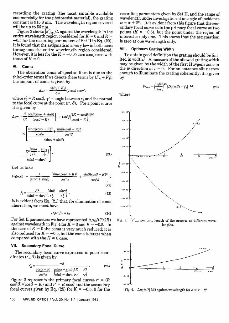
Figure 3 shows [Z']ast/L against the wavelength in theentire wavelength region considered for K = 0 and K =-0.5 for the recording parameters of Set II in Eq. (20).It is found that the astigmatism is very low in both casesthroughout the entire wavelength region considered.However, it is less for the K = -0.05 case compared withthose of K = 0.
VI. Coma
The aberration coma of spectral lines is due to thethird-order terms if we denote these terms by (F4 + F4);the amount of coma is given by
aF4+ F4 ) ApC = a r secO secy',
where r6 = R cost, Y' = angle between r and the normalto the focal curve at the point (r', ). For a point sourceit is given by
12 cosfl(sina + sing) t 2 2K-coS1211/'2
2R (cos - K) + os-K
rsinc(cos + K)2 + sin3(cosfl - K)2
X cos4a cos43
(sina + sinO)
recording parameters given by Set II, and the range ofwavelength under investigation at an angle of incidence
= r + 20. It is evident from this figure that the sec-ondary focal curve cuts the primary focal curve at twopoints (K = -0.5), but the point under the region ofinterest is only one. This shows that the astigmatismis zero at one wavelength only.
Vill. Optimum Grating Width
To obtain good definition the grating should be lim-ited in width.7 A measure of the allowed grating widthmay be given by the width of the first Huygens zone inthe w direction at I = 0. For an entrance slit narrowenough to illuminate the grating coherently, it is givenby
[D3(aOtw- f3]-1/3, (26)
where
10" 10-
8 10
6"10
KK-;
I
I
4 10Th
2" 10"
,2 I(s 2 2 - ) s
(sin - sin-y),
(21)
Let us take
D2(af) = 1 [sina(cosa + K)2 + sinfl(cos# - K)2 1(sina + sin3) cos 4 a cos4
'
(22)
- - 10 -
-0.5
20 30 -- 40 50_o~~~~~~;(M
I -2 10"
-4 10-
-6" 101-
-8" 10'/2= R
2 (sin6 sin.y(sinb - sin'y) rD rc (23)
It is evident from Eq. (21) that, for elimination of comaaberration, we must have
D2 (CeA) = f2- (24)
For Set II parameters we have represented ApC/(12/2R)against wavelength in Fig. 4 for K = 0 and K = -0.5. Inthe case of K = 0 the coma is very much reduced; it isalso reduced for K = -0.5, but the coma is larger whencompared with the K = 0 case.
Vil. Secondary Focal Curve
The secondary focal curve expressed in polar coor-dinates (rh,/) is given by
rh =-R
cosa + K (sina + sin:l _ Rcos2a sin-sin')rD rcl
-lo
-12 1 0o K I =0 "
Fig. 3. []at per unit length of the grooves at different wave-lengths.
4 10
(25) = d
Figure 2 represents the primary focal curves r' = (Rcos2f3)/(cosO - K) and r' = R cosO and the secondaryfocal curves given by Eq. (25) for K = -0.5, 0 for the
K -0.5
C ' __ _ I III
- K-0
-2" 10'
-4 10 'L
Fig. 4. Apc/(12 12R) against wavelength for a = Xr + 2°.
156 APPLIED OPTICS / Vol. 20, No. 1 / 1 January 1981
l l To lo
tor,2 13wopt = _) 1(V
K = -0.5
Resolution cm
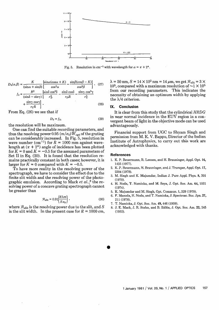
Fig. 5. Resolution in cm-1 with wavelength for a = r + 20.
K =sina(cosa + K) sin3(cos -K)
D3 (aO) = (sina + sinO) cos2a cos2I3
R2 fsinb cos26 sinb cos5 sin' cos2 'yf3 = _ __(sinb - siny) [ rF D rRc
sin'y cos-y
rcR
(27)
From Eq. (26) we see that if
D3 = f3 , (29)
the resolution will be maximum.One can find the suitable recording parameters, and
thus the resolving power 0.95 (m/cr0 ) Wopt of the gratingcan be considerably increased. In Fig. 5, resolution inwave number (cm- 1 ) for R = 1000 mm against wave-length at (Or + 2°) angle of incidence has been plottedfor K = 0 and K = -0.5 for the assumed parameters ofSet II in Eq. (20). It is found that the resolution re-mains practically constant in both cases; however, it islarger for K = 0 compared with K = -0.5.
To have more reality in the resolving power of thespectrograph, we have to consider the effect due to thefinite slit width and the resolving power of the photo-graphic emulsion. According to Mack et al. 8the re-solving power of a concave grating spectrograph cannotbe greater than
slit = 0.91 ) > (30)
where Bslit is the resolving power due to the slit, and Sis the slit width. In the present case for R = 1000 cm,
X = 50 nm, S = 14>X 103 nm = 14 Am, we get Rslit = 3 X10⁵, compared with a maximum resolution of -1 X 10⁵from our recording parameters. This indicates thenecessity of obtaining an optimum width by applyingthe X/4 criterion.
IX. Conclusion
It is clear from this study that the cylindrical HRDGin near normal incidence in the EUV region in a con-vergent beam of light in the objective mode can be usedadvantageously.
Financial support from UGC to Shyam Singh andpermission from M. K. V. Bappu, Director of the IndianInstitute of Astrophysics, to carry out this work areacknowledged with thanks.
References1. K. P. Beuermann, R. Lenzen, and H. Brauninger, Appl. Opt. 16,
1425 (1977).2. K. P. Beuermann, H. Brauninger, and J. Trumper, Appl. Opt. 17,
2304 (1978).3. M. Singh and K. Majumdar, Indian J. Pure Appl. Phys. 8, 201
(1970).4. H. Noda, T. Namioka, and M. Seya, J. Opt. Soc. Am. 64, 1031
(1974).5. K. Majumdar and M. Singh, Opt. Commun. 1, 329 (1970).6. F. Masuda, H. Noda, and T. Namioka, J. Spectrosc. Soc. Jpn. 27,
211 (1978).7. T. Namioka, J. Opt. Soc. Am. 49, 446 (1959).8. J. E. Mack, J. R. Stehn, and B. Edlen, J. Opt. Soc. Am. 22, 245
(1932).
1 January 1981 / Vol. 20, No. 1 / APPLIED OPTICS 157
11 1
9g "
7"-
~~5"
3"
-