hollow chisel mortiser - mike's tools · additional safety rules for hollow chisel mortisers 3...
TRANSCRIPT

INS
TRU
CTIO
NM
AN
UA
LHollow Chisel
Mortiser(Model 14-650)
PART NO. 900651 (011)Copyright © 2001 Delta Machinery
ESPAÑOL: PÁGINA 19To learn more about DELTA MACHINERY visit our website at: www.deltamachinery.com.For Parts, Service, Warranty or other Assistance,
please call 1-800-223-7278 (In Canada call 1-800-463-3582).

2
SAFETY RULESWoodworking can be dangerous if safe and proper operating procedures are not followed. As with all machinery, thereare certain hazards involved with the operation of the product. Using the machine with respect and caution willconsiderably lessen the possibility of personal injury. However, if normal safety precautions are overlooked or ignored,personal injury to the operator may result. Safety equipment such as guards, push sticks, hold-downs, featherboards,goggles, dust masks and hearing protection can reduce your potential for injury. But even the best guard won’t makeup for poor judgment, carelessness or inattention. Always use common sense and exercise caution in the workshop.If a procedure feels dangerous, don’t try it. Figure out an alternative procedure that feels safer. REMEMBER: Yourpersonal safety is your responsibility.
This machine was designed for certain applications only. Delta Machinery strongly recommends that this machine notbe modified and/or used for any application other than that for which it was designed. If you have any questions relativeto a particular application, DO NOT use the machine until you have first contacted Delta to determine if it can or shouldbe performed on the product.
Technical Service ManagerDelta Machinery4825 Highway 45 NorthJackson, TN 38305
(IN CANADA: 505 SOUTHGATE DRIVE, GUELPH, ONTARIO N1H 6M7)
WARNING: FAILURE TO FOLLOW THESE RULES MAY RESULT IN SERIOUS PERSONAL INJURY
1. FOR YOUR OWN SAFETY, READ INSTRUCTIONMANUAL BEFORE OPERATING THE TOOL. Learn thetool’s application and limitations as well as the specifichazards peculiar to it.
2. KEEP GUARDS IN PLACE and in working order.3. ALWAYS WEAR EYE PROTECTION.4. REMOVE ADJUSTING KEYS AND WRENCHES.
Form habit of checking to see that keys and adjustingwrenches are removed from tool before turning it “on”.5. KEEP WORK AREA CLEAN. Cluttered areas and
benches invite accidents.6. DON’T USE IN DANGEROUS ENVIRONMENT. Don’t
use power tools in damp or wet locations, or expose themto rain. Keep work area well-lighted.
7. KEEP CHILDREN AND VISITORS AWAY. All childrenand visitors should be kept a safe distance from work area.
8. MAKE WORKSHOP CHILDPROOF – with padlocks,master switches, or by removing starter keys.
9. DON’T FORCE TOOL. It will do the job better and besafer at the rate for which it was designed.10. USE RIGHT TOOL. Don’t force tool or attachment todo a job for which it was not designed.11. WEAR PROPER APPAREL. No loose clothing, gloves,neckties, rings, bracelets, or other jewelry to get caught inmoving parts. Nonslip footwear is recommended. Wearprotective hair covering to contain long hair.12. ALWAYS USE SAFETY GLASSES. Wear safetyglasses. Everyday eyeglasses only have impact resistantlenses; they are not safety glasses. Also use face or dustmask if cutting operation is dusty. These safety glassesmust conform to ANSI Z87.1 requirements. Note:Approved glasses have Z87 printed or stamped onthem.13. SECURE WORK. Use clamps or a vise to hold workwhen practical. It’s safer than using your hand and freesboth hands to operate tool.14. DON’T OVERREACH. Keep proper footing andbalance at all times.15. MAINTAIN TOOLS IN TOP CONDITION. Keep toolssharp and clean for best and safest performance. Followinstructions for lubricating and changing accessories.16. DISCONNECT TOOLS before servicing and whenchanging accessories such as blades, bits, cutters, etc.17. USE RECOMMENDED ACCESSORIES. The use ofaccessories and attachments not recommended by Deltamay cause hazards or risk of injury to persons.
18. R E D U C E T H E R I S K O F U N I N T E N T I O N A LSTARTING. Make sure switch is in “OFF” position beforeplugging in power cord.19. NEVER STAND ON TOOL. Serious injury could occurif the tool is tipped or if the cutting tool is accidentallycontacted.20. CHECK DAMAGED PARTS. Before further use of thetool, a guard or other part that is damaged should becarefully checked to ensure that it will operate properly andperform its intended function – check for alignment ofmoving parts, binding of moving parts, breakage of parts,mounting, and any other conditions that may affect itsoperation. A guard or other part that is damaged should beproperly repaired or replaced.21. DIRECTION OF FEED. Feed work into a blade orcutter against the direction of rotation of the blade or cutteronly.22. NEVER LEAVE TOOL RUNNING UNATTENDED.TURN POWER OFF. Don’t leave tool until it comes to acomplete stop.23. DRUGS, ALCOHOL, MEDICATION. Do not operatetool while under the influence of drugs, alcohol or anymedication.24. MAKE SURE TOOL IS DISCONNECTED FROMPOWER SUPPLY while motor is being mounted,connected or re-connected.25. THE DUST GENERATED by certain woods and woodproducts can be injurious to your health. Always operatemachinery in well ventilated areas and provide for properdust removal. Use wood dust collection systems wheneverpossible.
26. WARNING: SOME DUST CREATED BYPOWER SANDING, SAWING, GRINDING, DRILLING,AND OTHER CONSTRUCTION ACTIVITIES containschemicals known to cause cancer, birth defects or otherreproductive harm. Some examples of these chemicalsare:· lead from lead-based paints,· crystalline silica from bricks and cement and other
masonry products, and· arsenic and chromium from chemically-treated lumber. Your risk from these exposures varies, depending onhow often you do this type of work. To reduce yourexposure to these chemicals: work in a well ventilatedarea, and work with approved safety equipment, such asthose dust masks that are specially designed to filter outmicroscopic particles.
SAVE THESE INSTRUCTIONS

ADDITIONAL SAFETY RULES FORHOLLOW CHISEL MORTISERS
3
1. DO NOT operate your mortiser until it is completelyassembled and installed according to the instructions.
2. IF YOU ARE NOT thoroughly familiar with the operationof mortisers, obtain advice from your supervisor, instructor, orother qualified person.
3. MAKE CERTAIN the machine is fastened to a supportingsurface to prevent it from tipping over during operation.
4. NEVER turn the mortiser “ON” before clearing thetable of all objects (tools, scrap pieces, etc.).
5. ALWAYS keep hands, fingers and hair away fromthe rotating bit.
6. DO NOT attempt to mortise material that does nothave a flat surface, unless a suitable support is used.
7. ALWAYS position holddown directly over workpieceto prevent workpiece from lifting during operation.
8. ALWAYS support workpiece securely against fenceto prevent rotation.
9. BE SURE drill bit is sharp, not damaged, and properlysecured in the chuck before operation.
10. MAKE SURE chuck key is removed before startingmachine.
11. NEVER turn on the power with the drill bit or chiselcontacting the workpiece.
12. NEVER perform layout, assembly, or set-up work onthe table while the mortiser is operating.
13. ADJUST the depth stop to avoid drilling into thetable.
14. ALWAYS turn off the power before removing scrappieces from the table.
15. SHUT-OFF the power, remove the drill bit and chisel,and clean the table before leaving the machine.
16. FOR YOUR OWN SAFETY – Don’t wear gloves whenoperating the machine.
17. SHOULD any part of your tool be missing, damaged, orfail in any way, or any electrical component fail to performproperly, shut off switch and remove plug from powersupply outlet. Replace missing, damaged, or failed partsbefore resuming operation.
18. THE USE of attachments and accessories notrecommended by Delta may result in the risk of injuries.
19. ADDITIONAL INFORMATION regarding the safeand proper operation of this product is available fromthe National Safety Council, 1121 Spring Lake Drive,Itasca, IL 60143-3201 in the Accident PreventionManual for Industrial Operation and also in the SafetyData Sheets provided by the NSC. Please also refer tothe American National Standards Institute ANSI 01.1Safety Requirements for Woodworking Machinery andthe U.S. Depart-ment of Labor OSHA 1910.213Regulations.
20. GROUND ALL TOOLS. If tool is equipped with three-prong plug, it should be plugged into a three-hole electricalreceptacle. If an adapter is used to accommodate a two-prong receptacle, the adapter lug must be attached to aknown ground. Never remove the third prong.
21. WHEN THE TOOL IS NOT IN USE the switch shouldbe locked in the “OFF” position to prevent unauthorizeduse.
22. SAVE THESE INSTRUCTIONS. Refer to themfrequently and use them to instruct other users.

4
A - Mortising Machine
B - Hydraulic Cylinder
C - Raising and Lowering Handle
D - Special Screw (for raising and lowering handle)
E - Spring (for raising and lowering handle)
F - Table
G - M6 x 35mm Flat Head Screws (for assemblingtable to base)
H - T-Nuts (for assembling table to base)
J - Fence
K - Bar (for mounting holddown)
UNPACKING AND CLEANINGCarefully unpack the mortiser and all loose items from the carton. Remove the protective coating from the machinedsurfaces of the mortiser. This coating may be removed with a soft cloth moistened with kerosene. Do not use acetone,gasoline, or lacquer thinner for this purpose. Fig. 2 illustrates the mortiser and all loose items removed from the carton.
L - Holddown
M - Chuck Key
N - Wrench
O - Tool and Chisel Holder
P - M6 x 25mm Screws (for assembling tool andchisel
holder)
* - Flat Washers (for assembling tool and chisel holder)
R - Fence Locking Handle Assembly
* - Not Shown
Fig. 2
O
P
N
M
B
J
L
K
G
HF
GH
C
ED
R
A

5
ASSEMBLY INSTRUCTIONSWARNING: FOR YOUR OWN SAFETY, DO NOT CONNECT THE MACHINE TO THE POWER SOURCE UNTIL THE
MACHINE IS COMPLETELY ASSEMBLED AND YOU HAVE READ AND UNDERSTOOD THE ENTIRE OWNER’SMANUAL.
Fig. 3
ASSEMBLING RAISINGAND LOWERING HANDLE1. Assemble hub of handle assembly (A) Fig. 3, to endof pinion shaft (B) and fasten handle to pinion shaftusing special screw (C) and spring (D).
Fig. 4
Fig. 5
2. Raise mortising machine head (E) Fig. 4, to the upposition by turning handle (A) clockwise. NOTE: Handle(A) is spring-loaded and can be repositioned by pullingout handle and repositioning it on pinion shaft (B).
ASSEMBLINGHYDRAULIC CYLINDER1. Make sure head (A) Fig. 5, is held in the up positionand assemble the hydraulic cylinder (B) to the twofittings (C), one located on the column and the other onthe back of the head.
D C
AB
B
E
A
AC
C
B

6
Fig. 6
Fig. 7
Fig. 8
ASSEMBLING TABLE1. Assemble the table (A) Fig. 7, to the base using thetwo M6 x 35mm flat head screws (B) and T-nuts (C).Insert the two screws (B) into the two holes (D) in tableboard (A). Place the two T-nuts (C) into the slotsprovided in the bottom of the base and tighten the twoscrews (B) into the two T-nuts (C) securely.
2. The table (A) Fig. 7, can be moved in or out byloosening the two screws (B), and re-positioning thetable, and then tightening screws (B).
ASSEMBLING FENCEAND HOLDDOWN1. Locate handle assembly and remove screw (A) Fig. 8,and spring (B) from handle (C). Seperate handle (C) fromstud (D). Do not lose spring (B).
2. Fig. 6, illustrates the hydraulic cylinder (B) assembledto the machine. The hydraulic cylinder (B) keeps thehead in the up position.
B
A
BC
D
C
AB
D

7
Fig. 9
Fig. 10
Fig. 11
Fig. 12
2. Thread stud (D) Fig. 9, into hole on side of column,as shown. Do not thread stud (D) all the way into hole atthis time.
3. Reassemble handle (C) Fig. 9, on stud (D) and re-place screw (A) and spring (B).
4. Fig. 10 illustrates the handle assembly (C) assembledto the column.
5. Insert bar of fence assembly (E) Fig. 11, throughhole in column as shown. Tighten handle (C) against flaton fence bar to hold fence in position. NOTE: Handle (C)is spring-loaded and can be repositioned on the studlocated underneath the handle by pulling out the handleand repositioning it on the stud.
6. Insert bar (F) Fig. 12, into hole on top of fence asshown, and tighten set screw (G) against flat on bar (F).
D
C BA
C
C
E
F
G

8
Fig. 13
Fig. 14
Fig. 15
7. Assemble the holddown (H) Fig. 13, onto bar (F) asshown, and tighten set screw (J) against flat on bar.
ASSEMBLING TOOLAND CHISEL HOLDER1. Assemble tool and chisel holder (A) Fig. 14, to sideof column using the two M6 x 25mm screws (B) and flatwashers as shown.
2. Fig. 15, illustrates the chuck key (C), wrench (D) andchisels and bits (E) in holes of tool and chisel holder (A)when not in use.
FASTENING MORTISER TO SUPPORTING SURFACE
Fig. 16
This machine must be fastened to a supporting surfaceto prevent it from tipping during operation. Two holes aresupplied in the base casting to accept screws (A) Fig.16, for this purpose.
A
A
A
C
D
E
A
B
F
H
J

9
CONNECTING MORTISER TO POWER SOURCE
POWER CONNECTIONSA separate electrical circuit should be used for your tools. This circuit should not be less than #12 wire and should beprotected with a 20 Amp time lag fuse. If an extension cord is used, use only 3-wire extension cords which have 3-prong grounding type plugs and 3-pole receptacles which accept the tool’s plug. Before connecting the motor to thepower line, make sure the switch is in the “OFF” position and be sure that the electric current is of the samecharacteristics as indicated on the tool. All line connections should make good contact. Running on low voltage willdamage the motor.
GROUNDING INSTRUCTIONSCAUTION: THIS TOOL MUST BE GROUNDED WHILE IN USE TO PROTECT THE OPERATOR FROM ELECTRICSHOCK.
Fig. 17 Fig. 18
GROUNDED OUTLET BOX
CURRENTCARRYING
PRONGS
GROUNDING BLADEIS LONGEST OF THE 3 BLADES
GROUNDED OUTLET BOX
GROUNDING MEANS
ADAPTER
CAUTION: IN ALL CASES, MAKE CERTAIN THER E C E P TA C L E I N Q U E S T I O N I S P R O P E R LYGROUNDED. IF YOU ARE NOT SURE, HAVE AC E R T I F I E D E L E C T R I C I A N C H E C K T H ERECEPTACLE.
This tool is intended for use on a circuit that has an outletand a plug that looks like the one shown in Fig. 17. Atemporary adapter, which looks like the adapter illustratedin Fig. 18, may be used to connect this plug to a 2-polereceptacle, as shown in Fig. 18, if a properly groundedoutlet is not available. The temporary adapter should beused only until a properly grounded outlet can be in-stalled by a qualified electrician. THIS ADAPTER ISNOT APPLICABLE IN CANADA. The green-coloredrigid ear, lug, and the like, extending from the adaptermust be connected to a permanent ground, such as aproperly grounded outlet box, as shown in Fig. 18.
In the event of a malfunction or breakdown, groundingprovides a path of least resistance for electric current toreduce the risk of electric shock. The motor is equippedwith an electric cord having an equipment-groundingconductor and a grounding plug. The plug must beplugged into a matching outlet that is properly installedand grounded in accordance with all local codes andordinances.
Do not modify the plug provided - if it will not fit theoutlet, have the proper outlet installed by a qualifiedelectrician.
Improper connection of the equipment-groundingconductor can result in risk of electric shock. Theconductor with insulation having an outer surface that isgreen with or without yellow stripes is the equipment-grounding conductor. If repair or replacement of theelectric cord or plug is necessary, do not connect theequipment grounding conductor to a live terminal.
Check with a qualified electrician or service personnel ifthe grounding instructions are not completelyunderstood, or if in doubt as to whether the tool isproperly grounded.
Use only 3-wire extension cords that have 3-pronggrounding type plugs and 3-hole receptacles thataccept the tool’s plug, as shown in Fig. 17.
Repair or replace damaged or worn cord immediately.
10
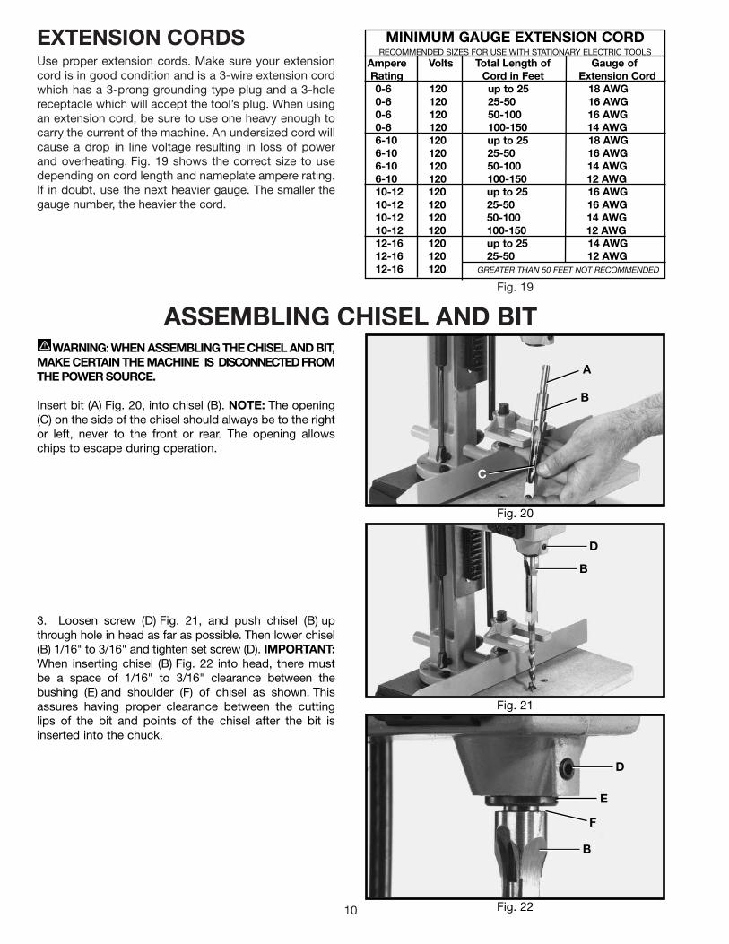
EXTENSION CORDSUse proper extension cords. Make sure your extensioncord is in good condition and is a 3-wire extension cordwhich has a 3-prong grounding type plug and a 3-holereceptacle which will accept the tool’s plug. When usingan extension cord, be sure to use one heavy enough tocarry the current of the machine. An undersized cord willcause a drop in line voltage resulting in loss of powerand overheating. Fig. 19 shows the correct size to usedepending on cord length and nameplate ampere rating.If in doubt, use the next heavier gauge. The smaller thegauge number, the heavier the cord.
Fig. 19
ASSEMBLING CHISEL AND BIT
Fig. 20
Fig. 21
Fig. 22
WARNING: WHEN ASSEMBLING THE CHISEL AND BIT,MAKE CERTAIN THE MACHINE IS DISCONNECTEDFROMTHE POWER SOURCE.
Insert bit (A) Fig. 20, into chisel (B). NOTE: The opening(C) on the side of the chisel should always be to the rightor left, never to the front or rear. The opening allowschips to escape during operation.
3. Loosen screw (D) Fig. 21, and push chisel (B) upthrough hole in head as far as possible. Then lower chisel(B) 1/16" to 3/16" and tighten set screw (D). IMPORTANT:When inserting chisel (B) Fig. 22 into head, there mustbe a space of 1/16" to 3/16" clearance between thebushing (E) and shoulder (F) of chisel as shown. Thisassures having proper clearance between the cuttinglips of the bit and points of the chisel after the bit isinserted into the chuck.
B
E
D
F
D
B
B
A
C
MINIMUM GAUGE EXTENSION CORDRECOMMENDED SIZES FOR USE WITH STATIONARY ELECTRIC TOOLS
Ampere Volts Total Length of Gauge ofRating Cord in Feet Extension Cord0-6 120 up to 25 18 AWG0-6 120 25-50 16 AWG0-6 120 50-100 16 AWG0-6 120 100-150 14 AWG6-10 120 up to 25 18 AWG6-10 120 25-50 16 AWG6-10 120 50-100 14 AWG6-10 120 100-150 12 AWG 10-12 120 up to 25 16 AWG10-12 120 25-50 16 AWG10-12 120 50-100 14 AWG10-12 120 100-150 12 AWG12-16 120 up to 25 14 AWG12-16 120 25-50 12 AWG 12-16 120 GREATER THAN 50 FEET NOT RECOMMENDED

11
Fig. 23
6. The flat portion of the bit should be adjusted to aminimum of 1/16" away from the bottom of the chisel, asshown in Fig. 25. For certain types of wood it may benecessary to increase this distance up to a maximum of3/16" clearance. This method assures having properclearance between the cutting lips of the bit and the pointsof the chisel.
Fig. 24
Fig. 25
5. Loosen set screw (D) Fig. 24, and push chisel (B) upagainst bottom of bushing (E), as shown, and tighten setscrew (D). This should provide the proper distance be-tween the cutting lips of the bit and the points of thechisel.
4. Push bit (A) Fig. 23, up through chisel and intochuck (G) as far as it will go, and then back the bit off1/16", and lock bit in chuck using chuck key supplied.
A
G
E
B
D
PUSHCHISEL UPAGAINSTBUSHING
ADJUST BIT INCHUCK TO GIVE
CLEARANCE
1/16" to 3/16"CLEARANCE TO SUITTYPE OF WOOD

12
OPERATING CONTROLS AND ADJUSTMENTS
Fig. 26
Fig. 27
Fig. 28
RAISING ANDLOWERING THE HEADThe head (A) Fig. 28, is raised and lowered by means ofthe lever (B). For maximum leverage during the mortisingoperation, the lever (B) can be repositioned by pullingout the hub (C) of the lever assembly and repositioninghub on the pinion shaft.
LOCKING SWITCH INTHE “OFF” POSITIONWhen the tool is not in use, the switch be locked in the“OFF” position to prevent unauthorized use. This can bedone by grasping the switch toggle (B) Fig. 27, andpulling it out of the switch, as shown. With the switchtoggle (B) removed, the switch will not operate.However, should the switch toggle be removed while themachine is running, the switch can be turned “OFF”once, but cannot be restarted without inserting theswitch toggle (B).
SWITCHThe switch (A) Fig. 26, is located on the side of themotor. To start the mortiser, move the switch (A) to theup position. To turn the mortiser “OFF” move the switchto the down position
A
B
B
C
A

13
Fig. 29
Fig. 30
Fig. 31
ADJUSTING CHISELPARALLEL TO WORKPIECEThe chisel (A) Fig. 31, can be adjusted parallel to theworkpiece by loosening screw (B) and rotating chiseluntil the back surface of the chisel is touchingworkpiece. Then tighten screw (B).
ADJUSTING FENCEThe fence (A) Fig. 30, can be moved in or out byloosening lever (B), sliding fence to the desired positionand tightening lever (B). NOTE: Lever (B) is spring-loadedand can be repositioned by pulling out on the lever andrepositioning it on the serrated nut located underneaththe lever.
ADJUSTING HOLDDOWNThe purpose of the holddown (C) Fig. 30, is to preventthe workpiece (E) from lifting as the chisel (D) is raisedup, out of the hole. The holddown (C) should be adjustedso it just touches the top of the workpiece (E) and allowsthe workpiece to slide left or right. The holddown (C) canbe turned upside down to accommodate thickerworkpieces. To adjust the holddown (C), loosen screw(F), position holddown, and tighten screw (F).
ADJUSTINGDEPTH STOP RODA depth stop rod (A) Fig. 29, is provided to limit thedepth of the chisel (B). To adjust the depth stop rod (A),loosen screw (C) and lower head until the chisel (B) isat the desired depth. Lower depth stop rod (A) until itcontacts base (D) and tighten screw (C). B
D
A
C
B
A
F
DC
E
B
A

14
Fig. 32
ADJUSTING SLIDINGFIT BETWEEN HEADAND COLUMNA dovetail gib (A) Fig. 32, is provided on the rear of thehead to insure a good sliding fit between the head andthe column when the head is raised and lowered.Adjustment is made by loosening the two screws (B) andturning adjusting screws (C). Then tighten two screws(B). NOTE: Correct adjustment is when a good snugsliding fit is obtained without any side movementbetween the gib and the column. This adjustmentshould not be too tight that it restricts the slidingmovement or too loose that it affects accuracy.
B
A
B
C
OPERATION
Fig. 33
Fig. 34
1. Make sure that chisels and bits are sharp.
2. Fig. 33, illustrates a typical mortising operation.Note that the opening (A) in the chisel is to the right. Thismeans that after the first incision is cut, the workpieceshould be moved to the right for subsequent cuts. Thisallows chips to escape freely through the opening in thechisel.
3. Make sure the workpiece is held firmly against thefence when cutting and that the holddown (B) Fig. 33, isproperly adjusted.The rate of penetration of the chiselmust be fast enough to prevent burning at the tip of thebit, but not too fast as to stall the motor. You may en-counter smoke from the bit or material once the chisel hasengaged the material. The smoke created is a naturaloperating occurrence in hollow chisel mortising and iscaused by material chip friction and the resins in thestock being burned off. Bluing of the chisel after initialuse is not indicative of a dull chisel, but a combinationof friction and resin buildup on the cutting faces of thechisel. A dull chisel can be detected by the amount ofexcess force required to complete a cut.
4. When performing a through mortise, a thin piece ofwood should be placed between the workpiece and thetable. This prevents “chip-out” at the bottom of themortise and also prevents damage to the table.
5. Fig. 34, illustrates the mortising operationcompleted.
B A

15
USING AUXILIARY WOOD FENCE
Fig. 35
When mortising extra high workpieces (A) Fig. 35, anauxiliary fence (B) can be fastened to the fence (C) withwood screws (D) through the two holes in the fence. Thisprovides additional support for the workpiece during themortising operation. Note that the holddown (E) can beturned upside down to accommodate the extra height ofthe workpiece.
ROTATING COLUMN 180 DEGREESThe column (A) Fig. 36, can be rotated 180 degrees, as shown, if it is desired to use workpieces off the table. To rotatethe column, remove three screws, two of which are shown at (B), rotate column (A) 180 degrees and replace the threescrews (B).
Fig. 36
B
C
D
E
A
A
B

16
USING BITS WITH EXTRA LONG SHANKS
Fig. 38
Fig. 37
When using bits with extra long shanks, it will benecessary to remove the extension (A) Fig. 37. This can beaccomplished by inserting screwdriver into center holeof motor end cap (B) Fig. 38, and into slot in end ofarmature shaft. Then using chuck key, unscrew andremove chuck (C) Fig. 37, and extension (A). Removeextension (A) from chuck (C) and replace chuck (C) onend of motor shaft.
A
C
B

17
NOTES

18
PARTS, SERVICE OR WARRANTY ASSISTANCE
Delta Building Trades and Home Shop MachineryTwo Year Limited Warranty
Delta will repair or replace, at its expense and at its option, any Delta machine,machine part, or machine accessory which in normal use has proven to be defectivein workmanship or material, provided that the customer returns the product prepaid toa Delta factory service center or authorized service station with proof of purchase ofthe product within two years and provides Delta with reasonable opportunity to verifythe alleged defect by inspection. Delta may require that electric motors be returnedprepaid to a motor manufacturer’s authorized station for inspection and repair orreplacement. Delta will not be responsible for any asserted defect which has resultedfrom normal wear, misuse, abuse or repair or alteration made or specifically authorizedby anyone other than an authorized Delta Service facility or representative. Under nocircumstances will Delta be liable for incidental or consequential damages resultingfrom defective products. This warranty is Delta’s sole warranty and sets forth thecustomer’s exclusive remedy, with respect to defective products; all other warranties,express or implied, whether of merchantability, fitness for purpose, or otherwise, areexpressly disclaimed by Delta.
All Delta Machines and accessories are manufactured to high quality standards and are serviced by a network of Porter-Cable•Delta Factory Service Centers and Delta Authorized Service Stations. To obtain additional information regardingyour Delta quality product or to obtain parts, service, warranty assistance, or the location of the nearest service outlet,please call 1-800-223-7278, (In Canada call 1-800-463-3582).