holistic approach to engineered, diversion-aided …€¦ · 7⅝” × 9⅝” liner hanger x-over...
TRANSCRIPT

SUMMER 2017 SAUDI ARAMCO JOURNAL OF TECHNOLOGY
ABSTRACT
In the current energy market, operators of unconventional as-sets must explore new methods that promise to dramatically reduce the cost of recovery per barrel of oil equivalent without adversely affecting production. To meet that need, a number of technologies focusing on expanding completion thresholds and mitigating bypassed reserves have recently come on the market. This article discusses an engineered approach to utilizing one such technology. The approach taken is a holistic petrophys-ical analysis, coupled with a novel control pressure pumping (CPP) technique, and deployment of degradable diversion pills within each stage to maximize fracture initiations and stimu-lated volume.
The industry has long assumed that fluid flow through per-forations is a relatively predictable phenomenon, given that little or no extrinsic evidence suggested otherwise. Recently, however, major advances in fiber optic technology, employed during both stimulation and production, have shown that flow is actually not equally distributed. During pumping operations, there can be great temporal variation in casing exit points af-fecting fluid flow; the addition of diversion brings further com-plexity to this already dynamic environment. To resolve this variability, an integrated approach was required. A progressive completion arrangement, aided by using petrophysical anal-ysis to define and select perforation cluster locations, using a new diagnostic fracture breakdown and propagation process to remedy the chaotic nature of initial flow distribution, and using well-defined diversion materials and processes to manage exit point discharge, was implemented.
Wells in the Jafurah area are typically drilled with approxi-mately 5,000 ft laterals. Over time, the challenge of improving cluster efficiency, optimizing cluster spacing and increasing the connected stimulated reservoir volume to enhance long-term well productivity has led to the introduction of several solu-tions, including increasing the number of clusters per stage, while consequently increasing the pumping rate, and using diversion technology.
INTRODUCTION
The development of unconventional resources in Saudi Arabia
is intended to address and meet the challenges of future energy demand at the local scale. The “de-risking” strategy for explo-ration and development of the source rocks builds upon the ex-periences gained from North American analogs. The company has addressed common completion challenges encountered in similar deposits and has developed a road map for testing potential technologies that could maximize a completion’s effi-ciency and overall well production.
The unconventional resources production engineering team studied intra-stage fluid diversion and cluster efficiency as ways to improve efficiency and cost. Previous studies confirmed that both have had an impact on well stimulation and production performance in other plays, along with advancements in the diagnostic tools used for the horizontal well intervention oper-ations, namely distributed acoustic sensing (DAS) and distrib-uted temperature sensing (DTS)1, 2.
Available techniques for evaluating cluster contribution and production have identified flow diversion problems in the Ja-furah Basin unconventional carbonate source rock, which is currently under exploration and development that are similar to problems in the North American plays. In the Jafurah wells, the lateral section historically was completed primarily with 16 stages per lateral, mainly utilizing the plug-and-perf technique, with three clusters per stage for transverse fracture develop-ment3. A transition from three-cluster stages to four-cluster stages was planned in hopes of gaining efficiency and maximiz-ing contact with the reservoir.
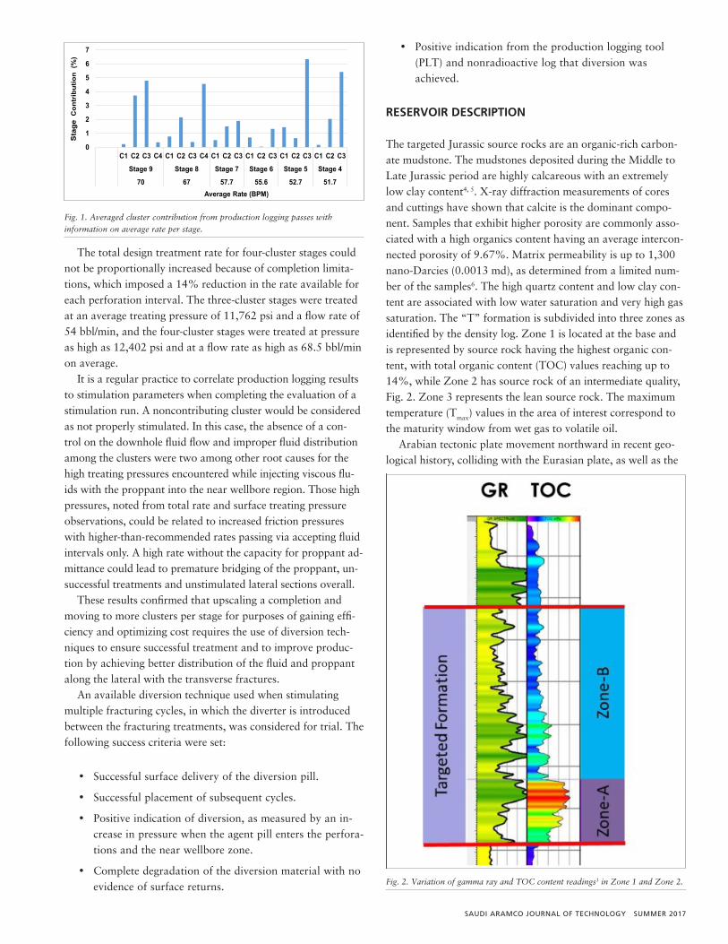
The first well treated with four clusters was landed within the homogeneous reservoir section without significant dip-ping, and geometrical spacing was considered along with the use of a similar treatment design. The initial three stages, with an increased number of perforation intervals at the toe section, resulted in screen outs and the need for subsequent wellbore clean out operations. In response, a conservative design ap-proach had to be applied, with a reduction of clusters back to three per stage. After gaining confidence, the number of clusters was again increased to four clusters in one stage, while still maintaining a conservative approach. The production log after the treatment showed clusters with poor to no contribution, and only one or two sets of perforations within the same stage showed a significant contribution based on a “flush” produc-tion evaluation, Fig. 1.
Holistic Approach to Engineered, Diversion-Aided Completion Providing a New Method of Fracture Isolation
Kirk M. Bartko, Kenneth M. McClelland, Almaz Sadykov, Sohrat Baki, Mohamed Khalifa, Mohamed Zeghouani and John Davis
SAUDI ARAMCO JOURNAL OF TECHNOLOGY SUMMER 2017
The total design treatment rate for four-cluster stages could not be proportionally increased because of completion limita-tions, which imposed a 14% reduction in the rate available for each perforation interval. The three-cluster stages were treated at an average treating pressure of 11,762 psi and a flow rate of 54 bbl/min, and the four-cluster stages were treated at pressure as high as 12,402 psi and at a flow rate as high as 68.5 bbl/min on average.
It is a regular practice to correlate production logging results to stimulation parameters when completing the evaluation of a stimulation run. A noncontributing cluster would be considered as not properly stimulated. In this case, the absence of a con-trol on the downhole fluid flow and improper fluid distribution among the clusters were two among other root causes for the high treating pressures encountered while injecting viscous flu-ids with the proppant into the near wellbore region. Those high pressures, noted from total rate and surface treating pressure observations, could be related to increased friction pressures with higher-than-recommended rates passing via accepting fluid intervals only. A high rate without the capacity for proppant ad-mittance could lead to premature bridging of the proppant, un-successful treatments and unstimulated lateral sections overall.
These results confirmed that upscaling a completion and moving to more clusters per stage for purposes of gaining effi-ciency and optimizing cost requires the use of diversion tech-niques to ensure successful treatment and to improve produc-tion by achieving better distribution of the fluid and proppant along the lateral with the transverse fractures.
An available diversion technique used when stimulating multiple fracturing cycles, in which the diverter is introduced between the fracturing treatments, was considered for trial. The following success criteria were set:
• Successful surface delivery of the diversion pill.
• Successful placement of subsequent cycles.
• Positive indication of diversion, as measured by an in-crease in pressure when the agent pill enters the perfora-tions and the near wellbore zone.
• Complete degradation of the diversion material with no evidence of surface returns.
• Positive indication from the production logging tool (PLT) and nonradioactive log that diversion was achieved.
RESERVOIR DESCRIPTION
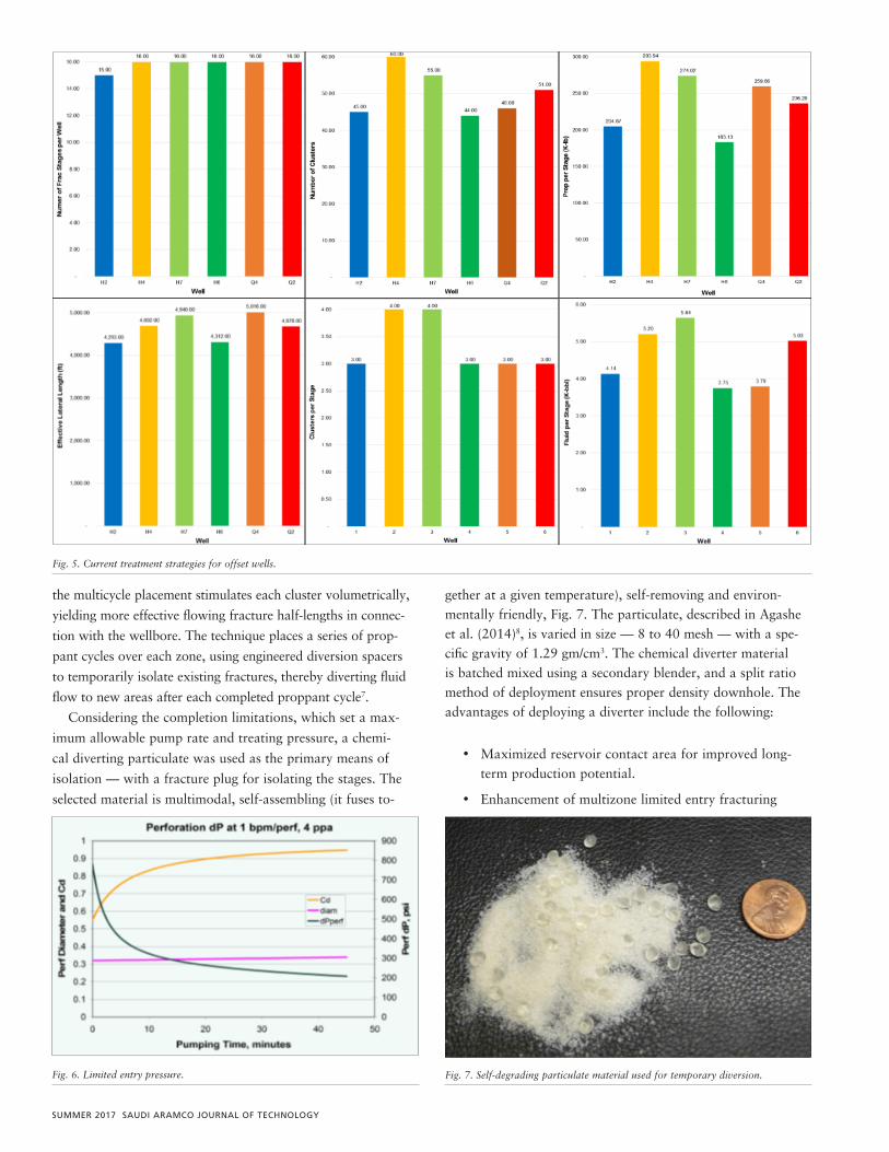
The targeted Jurassic source rocks are an organic-rich carbon-ate mudstone. The mudstones deposited during the Middle to Late Jurassic period are highly calcareous with an extremely low clay content4, 5. X-ray diffraction measurements of cores and cuttings have shown that calcite is the dominant compo-nent. Samples that exhibit higher porosity are commonly asso-ciated with a high organics content having an average intercon-nected porosity of 9.67%. Matrix permeability is up to 1,300 nano-Darcies (0.0013 md), as determined from a limited num-ber of the samples6. The high quartz content and low clay con-tent are associated with low water saturation and very high gas saturation. The “T” formation is subdivided into three zones as identified by the density log. Zone 1 is located at the base and is represented by source rock having the highest organic con-tent, with total organic content (TOC) values reaching up to 14%, while Zone 2 has source rock of an intermediate quality, Fig. 2. Zone 3 represents the lean source rock. The maximum temperature (Tmax) values in the area of interest correspond to the maturity window from wet gas to volatile oil.
Arabian tectonic plate movement northward in recent geo-logical history, colliding with the Eurasian plate, as well as the
Fig. 1
0
1
2
3
4
5
6
7
C1 C2 C3 C4 C1 C2 C3 C4 C1 C2 C3 C1 C2 C3 C1 C2 C3 C1 C2 C3
Stage 9 Stage 8 Stage 7 Stage 6 Stage 5 Stage 4
70 67 57.7 55.6 52.7 51.7
Sta
geC
ontr
ibut
ion
(%)
Average Rate (BPM)
Fig. 1. Averaged cluster contribution from production logging passes with information on average rate per stage.
Fig. 1. Averaged cluster contribution from production logging passes with information on average rate per stage.
Fig. 2. Variation of gamma ray and TOC content readings3 in Zone 1 and Zone 2.
Average Rate (BPM)
Fig. 2. Variation of gamma ray and TOC content readings3 in Zone 1 and Zone 2.

SUMMER 2017 SAUDI ARAMCO JOURNAL OF TECHNOLOGY
opening of the Red Sea determines the stress regime in the area. Overpressured source rock — viewed in light of sonic data in-terpretation, together with the diagnostic fracture injection test (DFIT) to analyze the pressure decline — confirmed a strike-slip stress regime at the target interval, with overburden stress providing an intermediate value of the three principal stresses. Hydraulic fractures in such a stress regime are expected to propagate in the direction parallel to maximum stress (sH), as in the case of a normal stress regime. Subsequently, challenges posed by the breakdown of different perforation clusters could be encountered, given the high laminations within the reservoir and the nonhomogeneous properties of the layers, and the pos-sibility existed of bottom-hole pressure exceeding overburden stress and leading to the development of a horizontal fracture component.
GEOMECHANICAL MODEL
Mechanical property tests were performed on selected core ma-terial to determine the anisotropic nature of the rock. The tests indicated the Jafurah Basin has a medium degree of anisotropy, with a static Young’s modulus ratio (Eh/Ev) of 1.65. The static Poisson’s ratio is approximately 1.38.
Multiple DFITs and mini-fracture diagnostic tests were pumped to estimate pore pressure, fracture closure pressure and fluid efficiency, formation characteristics and leakoff co-efficients. Table 1 summarizes the results of these diagnostics and the typical rock properties for one of the wells in the area of the Jafurah Basin.
COMPLETION STRATEGY
The Jafurah Basin wells average a total lateral length of 5,000 ft, which is based on operation constraints. The horizontal sec-tion is typically completed with a 4½”, Q-125 grade, 15.1 lb/ft cemented liner, Fig. 3, and a floating 5½”, C-95 grade, 20 lb/ft tubing tie-back to a 10,000 psi wellhead tree. All completion jewelry, except the wellhead tree, is rated for 15,000 psi. A well-head isolation tool (WHIT) is required to allow for the pumping of fracture jobs while isolating the wellhead components.
The Jafurah Basin’s horizontal wells were initially com-pleted with 16 fracturing stages; the perforation depths were selected by integrating petrophysics, a geomechanical earth model, image logs, cement bond logs and casing collar location data. The perforation strategy utilized three clusters with a separation of 60 ft to 80 ft. A single cluster was used at the toe to initiate the first fracture stage and to pump the DFIT to cal-ibrate the reservoir properties. Figure 4 shows a typical stage strategy in conjunction with a completion quality log.
Parameter Value Units
Young’s Modulus 3.8 Mpsi
Poisson’s Ratio 0.23 —
Shmin Gradient 0.96 psi/ft
Shmax Gradient 1.2 psi/ft
Pore Pressure Gradient 0.7-0.88 psi/ft
Table 1. DFIT analysis results6
Fig. 1
Fig. 3
30”
24” 18⅝”
5½” TBG
13⅜”
9⅝”
7”
7⅝” × 9⅝” Liner Hanger X-over 5½” × 4½”
No-Go Locator
Seal Unit and Sealbore Extension
Reducing Adapter
4½” Liner
4½”
Fig. 3. Current well completion design for initial wells3.

SAUDI ARAMCO JOURNAL OF TECHNOLOGY SUMMER 2017
Several fracturing strategies were tested to determine the operational efficiency, well performance and economics of the treatment. Initial results indicated a conventional cross-linked fracture treatment was the preferred design. Cross-linked frac-turing treatments became one of the preferred stimulation tech-niques in the basin, mostly due to their greater reliability given the existing wellhead configurations. Table 2 summarizes the typical fracture treatment applied in the Jafurah Basin.
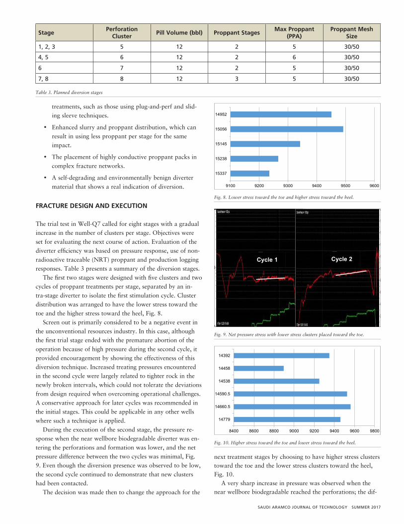
Several challenges were observed with the current comple-tion strategy, which limited the ability to increase the perfora-tion cluster density. Figure 5 provides examples of the current fracture strategies for offset wells.
Challenges related to the equipment limitations are:
• Wellhead configurations rated for 10,000 psi. Fracture operations used a WHIT to overcome this issue; however, using the tool lowered operation efficiency between stages, as extra time was required for rig up and rig down.
• Erosion of the upper section of the tubing, due to hang-ing of the WHIT, and changes on the internal diameter of the wellbore.
• Need to keep the pumping rate at approximately 60 bbl/min to 70 bbl/min to control surface pressure, due to the 4½” × 5½” tie-back completion limitations.
• The organic-rich laminated formations, which exhibited
high stress close to overburden pressures, causing high breakdown pressures.
CANDIDATE WELL SELECTION AND TECHNIQUE APPLIED
The testing of the effect of increasing the number of clusters required geosteering drilling of the lateral section. The criterion for the candidate well selection was a lateral that landed in ei-ther Zone 1 or 2, but did not undulate between the two layers. The goal was to drill the lateral heel in Zone 1 and allow the well to walk into Zone 2. Controlling the well placement al-lowed the perforation clusters to be selected based on expected breakdown pressures, given the geomechanical properties along the lateral. Other factors considered for the cluster spacing de-sign were the degree of stress shadowing, the limited entry pres-sures (approximately 400 psi), Fig. 6, and the rock fabric of the transition zone between the Zone 1 and Zone 2 rock.
Conventional multicluster fracturing techniques rely on lim-ited entry effects, or back pressure, to ensure adequate treat-ment coverage across each cluster. Typically, this is not sufficient to ensure each cluster receives an optimal dosage of the stage treatment. Diagnostic studies have shown that most fracturing treatments do not initiate and propagate a dominant fracture from all of the designed perforation clusters. This fact has been confirmed with PLTs and micro-seismic mapping studies, which have shown that on average only 50% to 60% of the perfor-mance clusters of a well contribute significantly to production. This is in addition to the geomechanical modeling work that has been consistently telling us that stress shadowing makes it very difficult to initiate interior fracture development and that divert-er-enabled sequential injection cycles are necessary to enhance the initiation points and the ultimate stimulated volume.
The intra-stage diversion technique uses multiple proppant cycles separated by diversion spacers to fully stimulate each zone in a primary completion, improving fracture distribution and generating more net pressure, enough to fracture the entire spec-trum of stresses encountered across the interval. Additionally,
Parameter Value Units Young’s Modulus 3.8 Mpsi Poisson’s Ratio 0.23 — Shmin Gradient 0.96 psi/ft Shmax Gradient 1.2 psi/ft Pore Pressure Gradient 0.7-0.88 psi/ft
Table 1. DFIT analysis results6
Fig. 3. Current well completion design for initial wells3.
Fig. 4. Completion quality log with cluster spacing strategy identified6.
Fig. 4. Completion quality log with cluster spacing strategy identified6.
Description Practice
Fluid per cluster 1,000 to 1,400 bbl
Proppant per cluster 100,000 lb
Maximum proppant concentration
4 to 6 ppa
Fracturing treatment rate 40 to 70 bpm
Proppant type100-mesh sand, 40/70,
30/50 and 20/40 ceramic proppant
Table 2. Stimulation design summary
SUMMER 2017 SAUDI ARAMCO JOURNAL OF TECHNOLOGY
the multicycle placement stimulates each cluster volumetrically,
yielding more effective flowing fracture half-lengths in connec-
tion with the wellbore. The technique places a series of prop-
pant cycles over each zone, using engineered diversion spacers
to temporarily isolate existing fractures, thereby diverting fluid
flow to new areas after each completed proppant cycle7.
Considering the completion limitations, which set a max-
imum allowable pump rate and treating pressure, a chemi-
cal diverting particulate was used as the primary means of
isolation — with a fracture plug for isolating the stages. The
selected material is multimodal, self-assembling (it fuses to-
gether at a given temperature), self-removing and environ-mentally friendly, Fig. 7. The particulate, described in Agashe et al. (2014)8, is varied in size — 8 to 40 mesh — with a spe-cific gravity of 1.29 gm/cm3. The chemical diverter material is batched mixed using a secondary blender, and a split ratio method of deployment ensures proper density downhole. The advantages of deploying a diverter include the following:
• Maximized reservoir contact area for improved long-term production potential.
• Enhancement of multizone limited entry fracturing
Description Practice Fluid per cluster 1,000 to 1,400 bbl Proppant per cluster 100,000 lb Maximum proppant concentration
4 to 6 ppa
Fracturing treatment rate 40 to 70 bpm Proppant type 100-mesh sand, 40/70, 30/50 and 20/40 ceramic
proppant Table 2. Stimulation design summary
Fig. 5. Current treatment strategies for offset wells. Fig. 6. Limited entry pressure.
Fig. 6. Limited entry pressure. Fig. 7. Self-degrading particulate material used for temporary diversion.
Stage Perforation
Cluster Pill Volume
(bbl) Proppant Stages
Max Proppant (PPA)
Proppant Mesh Size
1, 2, 3 5 12 2 5 30/50 4, 5 6 12 2 6 30/50 6 7 12 2 5 30/50 7, 8 8 12 3 5 30/50
Table 3. Planned diversion stages
Fig. 8. Lower stress toward the toe and higher stress toward the heel.
Fig. 9. Net pressure stress with lower stress clusters placed toward the toe.
Fig. 7. Self-degrading particulate material used for temporary diversion.
Fig. 5
Fig. 8
9100 9200 9300 9400 9500 9600
15337
15238
15145
15056
14952
Fig. 5. Current treatment strategies for offset wells.
SAUDI ARAMCO JOURNAL OF TECHNOLOGY SUMMER 2017
treatments, such as those using plug-and-perf and slid-ing sleeve techniques.
• Enhanced slurry and proppant distribution, which can result in using less proppant per stage for the same impact.
• The placement of highly conductive proppant packs in complex fracture networks.
• A self-degrading and environmentally benign diverter material that shows a real indication of diversion.
FRACTURE DESIGN AND EXECUTION
The trial test in Well-Q7 called for eight stages with a gradual increase in the number of clusters per stage. Objectives were set for evaluating the next course of action. Evaluation of the diverter efficiency was based on pressure response, use of non-radioactive traceable (NRT) proppant and production logging responses. Table 3 presents a summary of the diversion stages.
The first two stages were designed with five clusters and two cycles of proppant treatments per stage, separated by an in-tra-stage diverter to isolate the first stimulation cycle. Cluster distribution was arranged to have the lower stress toward the toe and the higher stress toward the heel, Fig. 8.
Screen out is primarily considered to be a negative event in the unconventional resources industry. In this case, although the first trial stage ended with the premature abortion of the operation because of high pressure during the second cycle, it provided encouragement by showing the effectiveness of this diversion technique. Increased treating pressures encountered in the second cycle were largely related to tighter rock in the newly broken intervals, which could not tolerate the deviations from design required when overcoming operational challenges. A conservative approach for later cycles was recommended in the initial stages. This could be applicable in any other wells where such a technique is applied.
During the execution of the second stage, the pressure re-sponse when the near wellbore biodegradable diverter was en-tering the perforations and formation was lower, and the net pressure difference between the two cycles was minimal, Fig. 9. Even though the diversion presence was observed to be low, the second cycle continued to demonstrate that new clusters had been contacted.
The decision was made then to change the approach for the
next treatment stages by choosing to have higher stress clusters toward the toe and the lower stress clusters toward the heel, Fig. 10.
A very sharp increase in pressure was observed when the near wellbore biodegradable reached the perforations; the dif-
Fig. 9. Net pressure stress with lower stress clusters placed toward the toe.
StagePerforation
ClusterPill Volume (bbl) Proppant Stages
Max Proppant (PPA)
Proppant Mesh Size
1, 2, 3 5 12 2 5 30/50
4, 5 6 12 2 6 30/50
6 7 12 2 5 30/50
7, 8 8 12 3 5 30/50
Table 3. Planned diversion stages
Fig. 5
Fig. 8
9100 9200 9300 9400 9500 9600
15337
15238
15145
15056
14952
Fig. 8. Lower stress toward the toe and higher stress toward the heel.
Fig. 10. Higher stress toward the toe and lower stress toward the heel.
Fig. 9
Fig. 10
8400 8600 8800 9000 9200 9400 9600 9800
14779
14660.5
14590.5
14538
14458
14392
Cycle 1 Cycle 2
Fig. 9
Fig. 10
8400 8600 8800 9000 9200 9400 9600 9800
14779
14660.5
14590.5
14538
14458
14392
Cycle 1 Cycle 2
Fig. 9
Fig. 10
8400 8600 8800 9000 9200 9400 9600 9800
14779
14660.5
14590.5
14538
14458
14392
Cycle 1 Cycle 2 Cycle 2
Fig. 9
Fig. 10
8400 8600 8800 9000 9200 9400 9600 9800
14779
14660.5
14590.5
14538
14458
14392
Cycle 1 Cycle 2 Cycle 1

SUMMER 2017 SAUDI ARAMCO JOURNAL OF TECHNOLOGY
ference in the net pressure response was substantial between
the two cycles, indicating diverter constrained flow paths and
stimulation of new clusters, Fig. 11.
After the execution of the first treatments and an evaluation
of the formation response to the diversion and of surface effi-
ciency, we had the confidence to target eight clusters with three
cycles separated by two diversion intra-stages.
Figure 12 records where three proppant cycles, separated
with two near wellbore biodegradable diversion intra-stages,
have been successfully placed into the formation through eight clusters.
The main objective of using a diverter on Well-Q7 was to optimize the stimulation parameters by reducing the number of stages while still maintaining the same number of clusters as in the offset wells. Normally, the effective stimulation of a high number of clusters in one stage requires an increase in the pump rate to ensure proper diversion between the clusters. But the pump rate was limited to 60 bbl/min to 70 bbl/min in Well-Q7 because of completion limitations, due to tubing and liner size, and because of surface limitations, attributable to us-ing the WHIT. The use of the diversion technique made it pos-sible to get around the rate limitation and still meet the limited entry perforation friction requirements.
The number of stages was reduced without compromising the stimulated reservoir area and the productivity of the well. Three proppant cycles with eight clusters in each stage were placed successfully in six hours. This showed that it was pos-sible to improve the efficiency of the operations by cutting the number of intervention operations, and thereby eliminating the rig up and rig down necessitated by use of the WHIT, as well as reducing the coiled tubing milling time by having fewer frac-ture plugs in the lateral. Overall, the diversion technique should help to accelerate the process of optimizing the entire uncon-ventional completion operations of the Jafurah Basin.
Fig. 11. Net pressure profile with higher stress clusters placed toward the toe.
Fig. 12. Treatment plot for three cycles.
Fig. 10. Higher stress toward the toe and lower stress toward the heel.
Fig. 11. Net pressure profile with higher stress clusters placed toward the toe.
Fig. 112. Treatment plot for three cycles.
12/28/201521:00 22:00 23:00
12/29/201500:00 01:00
12/29/201502:00
Time
0
2000
4000
6000
8000
10000
12000
14000A
0
20
40
60
80
100
120
140B
0
2
4
6
8
10
12
14
16
18
20C
Treating Pressure (psi) Slurry Rate (bpm)Slurry Proppant Conc (lb/gal) BH Proppant Conc (lb/gal)Backside Pressure (psi)
A BC CA
Customer: SAUDI ARAMCO Job Date: 28-Dec-2015 Sales Order #: 903019119Well Description: QDQD 7 UWI:
Time
Fig. 10. Higher stress toward the toe and lower stress toward the heel.
Fig. 11. Net pressure profile with higher stress clusters placed toward the toe.
Fig. 112. Treatment plot for three cycles.
12/28/201521:00 22:00 23:00
12/29/201500:00 01:00
12/29/201502:00
Time
0
2000
4000
6000
8000
10000
12000
14000A
0
20
40
60
80
100
120
140B
0
2
4
6
8
10
12
14
16
18
20C
Treating Pressure (psi) Slurry Rate (bpm)Slurry Proppant Conc (lb/gal) BH Proppant Conc (lb/gal)Backside Pressure (psi)
A BC CA
Customer: SAUDI ARAMCO Job Date: 28-Dec-2015 Sales Order #: 903019119Well Description: QDQD 7 UWI:
Cycle 2
Cycle 1
SAUDI ARAMCO JOURNAL OF TECHNOLOGY SUMMER 2017
CONTROL PRESSURE PUMPING
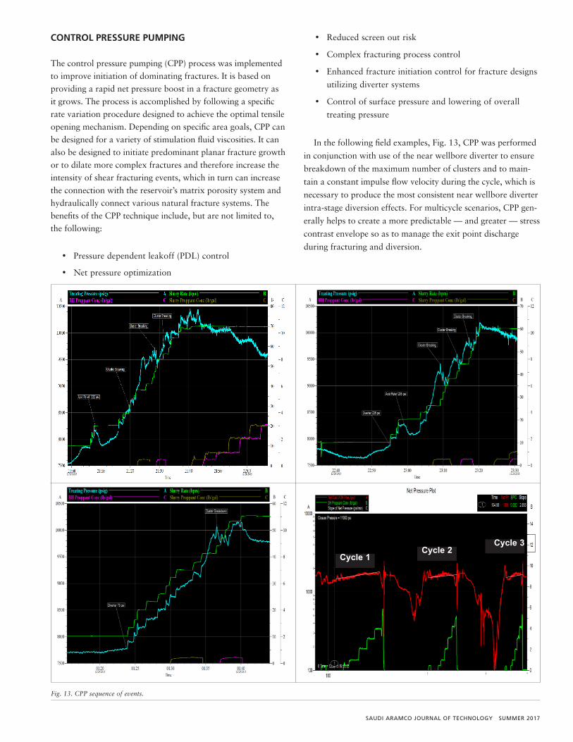
The control pressure pumping (CPP) process was implemented to improve initiation of dominating fractures. It is based on providing a rapid net pressure boost in a fracture geometry as it grows. The process is accomplished by following a specific rate variation procedure designed to achieve the optimal tensile opening mechanism. Depending on specific area goals, CPP can be designed for a variety of stimulation fluid viscosities. It can also be designed to initiate predominant planar fracture growth or to dilate more complex fractures and therefore increase the intensity of shear fracturing events, which in turn can increase the connection with the reservoir’s matrix porosity system and hydraulically connect various natural fracture systems. The benefits of the CPP technique include, but are not limited to, the following:
• Pressure dependent leakoff (PDL) control
• Net pressure optimization
• Reduced screen out risk
• Complex fracturing process control
• Enhanced fracture initiation control for fracture designs
utilizing diverter systems
• Control of surface pressure and lowering of overall
treating pressure
In the following field examples, Fig. 13, CPP was performed
in conjunction with use of the near wellbore diverter to ensure
breakdown of the maximum number of clusters and to main-
tain a constant impulse flow velocity during the cycle, which is
necessary to produce the most consistent near wellbore diverter
intra-stage diversion effects. For multicycle scenarios, CPP gen-
erally helps to create a more predictable — and greater — stress
contrast envelope so as to manage the exit point discharge
during fracturing and diversion.
Fig. 13. CPP sequence of events.
Fig. 213. CPP sequence of events.
Stage Number
Number of Clusters
Number of Cycles
NRT Proppant Amount per Cycle 1
NRT Proppant Amount per Cycle 2
Stage 1 5 Clusters 2 25,000 20,000 Stage 2 5 Clusters 2 — 20,000 Stage 3 6 Clusters 2 25,000 25,000 Stage 4 6 Clusters 2 — 25,000 Stage 5 6 Clusters 2 — 20,000 Stage 6 8 Clusters 3* 25,000 25,000 Stage 7 8 Clusters 2 25,000 25,000 Stage 8 8 Clusters 2 25,000 25,000
Table 4. 30/50 NRT proppant distribution
Cycle 1
Cycle 2 Cycle 3
Fig. 213. CPP sequence of events.
Stage Number
Number of Clusters
Number of Cycles
NRT Proppant Amount per Cycle 1
NRT Proppant Amount per Cycle 2
Stage 1 5 Clusters 2 25,000 20,000 Stage 2 5 Clusters 2 — 20,000 Stage 3 6 Clusters 2 25,000 25,000 Stage 4 6 Clusters 2 — 25,000 Stage 5 6 Clusters 2 — 20,000 Stage 6 8 Clusters 3* 25,000 25,000 Stage 7 8 Clusters 2 25,000 25,000 Stage 8 8 Clusters 2 25,000 25,000
Table 4. 30/50 NRT proppant distribution
Cycle 1
Cycle 2 Cycle 3 Cycle 1
Cycle 2Cycle 3

SUMMER 2017 SAUDI ARAMCO JOURNAL OF TECHNOLOGY
EVALUATION
NRT proppant was pumped in the sequence shown in Table 4 to evaluate the technology by adding NRT proppant logging data to the production log. NRT proppant use in near well-bore applications can be used to accurately identify proppant placement. The NRT proppant pumped during a stimulation treatment contains a high thermal neutron capture compound that is dispersed throughout the proppant during the manufac-turing process. This unique NRT eliminates the need for radio-active tracers and does not degrade over time, thereby allowing logging operations to be conducted throughout the life of the well. The pulsed neutron logging tool should be run before and after performing the main stimulation treatment. The pre-stim-
ulation pulsed neutron log, which will be used as a baseline, should be recorded during open hole logging of the lateral sec-tion. This baseline, when compared to the post-stimulation pulsed neutron log, should identify areas of depressed neutron response, signifying the presence of proppant.
NRT proppant was also used as a tail-in (10%) to determine if proper diversion was achieved. A total amount up to 335 K-lb of 30/50 high strength proppant/NRT proppant was re-quired. In some of the stages, NRT was pumped in the last cy-cle only, to confirm through comparisons with the production log that clusters without NRT proppant were contributing.
The proppant distribution among all clusters was confirmed by the logging run recorded to trace the 30/50 NRT prop-pant, indicating the success of the diversion, Fig. 14. Track 4
Stage Number Number of Clusters Number of CyclesNRT Proppant Amount
per Cycle 1NRT Proppant Amount
per Cycle 2
Stage 1 5 Clusters 2 25,000 20,000
Stage 2 5 Clusters 2 — 20,000
Stage 3 6 Clusters 2 25,000 25,000
Stage 4 6 Clusters 2 — 25,000
Stage 5 6 Clusters 2 — 20,000
Stage 6 8 Clusters 3* 25,000 25,000
Stage 7 8 Clusters 2 25,000 25,000
Stage 8 8 Clusters 2 25,000 25,000
Table 4. 30/50 NRT proppant distribution
Fig. 14. PLT and NRT distribution across the clusters.
Fig. 14. PLT and NRT distribution across the clusters.

SAUDI ARAMCO JOURNAL OF TECHNOLOGY SUMMER 2017
indicates the presence of NRT by its separation of the neutron response. Track 5 provides the contribution per cluster based on the PLT logs. Both logs indicated good contribution between the perforation clusters.
CONCLUSIONS
The success of the near wellbore biodegradable diverter was confirmed by pumping pressure observations and post-logging diagnostics. The volume that went into each cluster could not be assessed because there was no microsiesmic monitoring or DAS/DTS, which would have provided a measurement of the overall effectiveness of the diverter. Production response is not discussed in the article; however, Well-Q7 produced as ex-pected, indicating that the reduction in fracture stages did not impair productivity. Based on pressure data and near wellbore diagnostic tools, the following conclusions can be made:
• The control pressure pumping process appears to have broken down new perforations, based on pressure re-sponses from the individual rate increases. The conserva-tive — nonaggressive — design should be considered as a contingency for subsequent stages.
• Pressure responses to the near wellbore biodegradable diverter and post-analysis indicated that the diversion occurred downhole.
• Eight-cluster stages were successful, with proppant slurry entering each cluster.
• The pulsed neutron log indicates proppant entry into the perforation clusters and transverse fractures development.
• No operational complications resulted from the pumping of the near wellbore biodegradable diverter.
• Additional volume and placement optimization of the near wellbore biodegradable diverter will provide greater success in spreading the proppant slurry among the per-foration clusters.
• Diversion technology can successfully reduce the number of stages and improve operation efficiencies.
• An on-the-fly diverter injection procedure is recom-mended to maintain near wellbore conductivity, rather than the low split ratio method.
ACKNOWLEDGMENTS
The authors would like to thank the management of both Saudi Aramco and Halliburton for permission to publish the article and to the operational personnel on location for suc-cessfully performing the numerous required operations.
This article was presented at the SPE Hydraulic Fractur-ing Technology Conference and Exhibition, The Woodlands, Texas, January 24-26, 2017.
REFERENCES
1. Wheaton, B., Haustveit, K., Deeg, W., Miskimins, J., et al.: “A Case Study of Completion Effectiveness in the Eagle Ford Shale Using DAS/DTS Observations in Hydraulic Fracture Modeling,” SPE paper 179149, presented at the SPE Hydraulic Fracturing Technology Conference, The Woodlands, Texas, February 9-11, 2016.
2. Ramurthy, M., Richardson, J., Brown, M., Sahdev, N., et al.: “Fiber Optics Results from an Intra-Stage Diversion Design Completions Study in the Niobrara Formation of DJ Basin,” SPE paper 179106, presented at the SPE Hydraulic Fracturing Technology Conference, The Woodlands, Texas, February 9-11, 2016.
3. Al-Mulhim, N.I., Korosa, M., Amed, A., Hakami, A., et al.: “Saudi Arabia’s Emerging Unconventional Carbonate Shale Resources: Moving to Horizontals with an Integrated Engineering and Geosciences Approach,” SPE paper 176936, presented at the Asia Pacific Unconventional Resources Conference and Exhibition, Brisbane, Australia, November 9-11, 2015.
4. Al Duhailian, M., Boudjatit, M., Yeh, N-S., Kurison, I.L.C., et al.: “Integrated Analysis of Abnormal Pressures in Source Rocks: Theory and Implications for Jurassic Unconventional Resource Exploration in Saudi Arabia,” URTEC paper 2441597, presented at the Unconventional Resources Technology Conference, San Antonio, Texas, August 1-3, 2016.
5. Hakami, A. and Inan, S.: “A Basin Modeling Study of the Jafurah Sub-Basin, Saudi Arabia: Implications for Unconventional Hydrocarbon Potential of the Jurassic Tuwaiq Mountain Formation,” International Journal of
Coal Geology, Vol. 165, August 2016, pp. 201-222.
6. Al-Momin, A., Kurdi, M., Baki, S., Mechkak, K., et al.: “Proving the Concept of Unconventional Gas Reservoirs in Saudi Arabia through Multistage Fractured Horizontal Wells,” SPE paper 176844, presented at the Asia Pacific Unconventional Resources Conference and Exhibition, Brisbane, Australia, November 9-11, 2015.
7. Loya, R. and Lahman, M.: “New Interventionless Fracturing Technique Rescues Stranded Assets,” E&P, September 2014, http://www.epmag.com/new-intervention-less-fracturing-technique-rescues-stranded-assets-721501, accessed October 25, 2016.
8. Agashe, S., Patil, P., Raysoni, N. and Pandya, N.: “Design and Development of Non-aqueous Suspension for Suspending Varied Sized Solid Particulates as a Conventional Diverter,” SPE paper 172201, presented at the SPE Saudi Arabia Section Annual Technical Symposium and Exhibition, al-Khobar, Saudi Arabia, April 21-24, 2014.

SUMMER 2017 SAUDI ARAMCO JOURNAL OF TECHNOLOGY
BIOGRAPHIES
Kirk M. Bartko is a Senior Petroleum Engineering Consultant with Saudi Aramco’s Unconventional Gas Operations Department. He is a member of the Technical Support Unit focusing on trial testing of new technologies for completions and
stimulation. In 2000, Kirk joined Saudi Aramco, where he works to support hydraulic fracturing and completion technologies across all Saudi Arabia operations. His experience includes 19 years with ARCO supporting U.S. and international operations through various global assignments in locations including Texas, Alaska, Algeria and the Research Technology Center.
Kirk has authored and coauthored more than 40 technical papers on well stimulation and is a recipient of four U.S. granted patents. He has been actively involved in the Society of Petroleum Engineers (SPE) since 1977.
Kirk received his B.S. degree in Petroleum Engineering from the University of Wyoming, Laramie, WY.
Kenneth M. McClelland joined Saudi Aramco in 2013. He is currently the Technical Support Unit Supervisor for the Unconventional Production Engineering Division of the Well Completion Operations and Production Engineering Department.
Kenneth has 18 years of experience in the oil and gas industry, including working as a Team Leader for Santos, Australia; Senior Completions/Operations Engineer for Occidental of Elk Hills, CA; and in various technical and management roles for Schlumberger in Indonesia, Saudi Arabia, Australia, Angola, U.K. and the U.S. He also has operational and technical training in fracking, coiled tubing (CT) and CT-related operations, for both oil and gas wells located onshore and offshore.
Kenneth received his B.S. degree (with honors) in Mechanical Engineering from Curtin University, Perth, Western Australia, and his M.S. degree in Business and Technology from the University of New South Wales, Sydney, Australia.
Almaz Sadykov joined Saudi Aramco in 2013 as a Petroleum Engineer in the Unconventional Production Engineering Division, where he works on rigless activity in the Jafurah, Rub’ al-Khali and South Ghawar areas, with extensive utilization of the
plug-and-perf technique for stimulating unconventional gas wells. Prior to joining Saudi Aramco, Almaz worked for 8 years in stimulation and well production engineering with Schlumberger. In his last 6 years with Schlumberger, he was involved in the design and evaluation of stimulation jobs, completions of oil and gas wells with multistage fracturing systems, and production enhancement.
Almaz received his M.S. degree in Petroleum Engineering from the Ufa State Petroleum Technological University, Ufa, Russia.
Sohrat Baki joined Saudi Aramco in December 2013 as a Petroleum Engineer working in the Unconventional Well Completion Operations Department and Unconventional Production Engineering Division. He started his
professional career in 2004 with Schlumberger Oilfield Services as a Stimulation Field Engineer in Western Siberia, Russia. Sohrat spent 6 years with Schlumberger in Russia, the North Sea and Europe, where he held additional DESC and Technical Support Engineer positions. Sohrat later spent 3 years with two service companies in the North Sea and Turkey, where he gained further experience in unconventional resources stimulation, production and project management.
Sohrat’s upstream expertise covers production engineering, fracturing, wireline, coiled tubing and project management in exploration and development phases.
In 2003, he received his B.S. degree in Petroleum Engineering from Istanbul Technical University, Istanbul, Turkey.

SAUDI ARAMCO JOURNAL OF TECHNOLOGY SUMMER 2017
Mohamed Khalifa is currently the Halliburton Stimulation Technical Lead in Saudi Arabia. He joined Halliburton, working in production enhancement in operations, and worked his way up from Stimulation Engineer to Senior Account
Representative. Mohamed has extensive experience in production engineering, petrophysics, well analysis and stimulation evaluation, in both onshore and offshore wells. He has 15 years of experience in stimulation and well completions, including conventional and unconventional hydraulic fracturing, hybrid fracturing, high rate water fracturing, fracpac, acid fracturing, carbonate acid stimulation, sandstone acid stimulation, pinpoint stimulation for vertical and horizontal wells, AccessFrac and conductor fracture.
Mohamed received his B.S. degree in Mechanics and Evaluation Engineering from Cairo University of Technology, Cairo, Egypt.
Mohamed Zeghouani is a Senior Stimulation Engineer at Halliburton, with more than 10 years of experience in oil and gas reservoir stimulation, production operations and petroleum engineering support. After 5 years of working in coiled tubing engineering,
during which he received several internal awards for successful achievements, Mohamed moved to fracturing engineering, where he was involved in the initial shale gas project in Algeria, coordinating the integrated solutions for the main oil and gas operator in that country.
In 2014, Mohamed joined Halliburton’s Fracturing Team in Saudi Arabia and worked mainly in south Ghawar. He also served as the Senior Fracturing Engineer for unconventional stimulation treatments in remote locations. Mohamed is currently part of the Halliburton Tech Team working with Saudi Aramco’s Gas Reservoir Management Department. He has extensive technical knowledge and experience in stimulation, conformance, reservoir engineering and new oil and gas industry technologies such as diversion, channel fracturing, pinpoint stimulation and water shut-off. Mohamed has total responsibility for Saudi Aramco’s oil and gas producers operating in the major domestic onshore/offshore basins.
In 2003, he received his B.S. degree in Production Engineering from the Algerian National Institute of Hydrocarbon and Chemistry, Boumerdes, Algeria.
John Davis is currently the Technology Manager for the Middle East and North Africa region of the Production Enhancement service line at Halliburton, where his main focus is the application and support of both existing and new technology. This
includes aiding the technical teams of several countries with organic growth support of their efforts to provide optimized solutions for both conventional and unconventional gas/oil reservoirs. John’s expertise is in the area of production enhancement with significant emphasis on acidizing, fracturing and conformance well activities. He has covered a variety of operational, technical and managerial roles in his 14 years in the industry. John has global experience in various regions of the world, including the North Sea (all sectors), the U.S. (various states), West Africa (various countries) and the Middle East (various countries).
He received his B.Eng. degree (with honors) in Offshore (Civil) Engineering and an M.S. degree in Petroleum Engineering, both awarded by Heriot-Watt University, Edinburgh, U.K.