hlb inst hlb 06/15 - downloads.halfen.com · hlb inst_hlb 06/15 assembly instructions •...
TRANSCRIPT
HLB INST_HLB 06/15
Assembly Instructions • Montageanleitung • Notice d‘utilisation • Instrukcja montażu
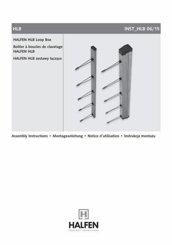
HALFEN HLB Loop Box
Boîtier à boucles de clavetageHALFEN HLB
HALFEN HLB zestawy łączące
2 © 2015 HALFEN · Inst_HLB 06/15 · www.halfen.com
HLB Assembly InstructionsD
euts
chEn
glis
hFr
ança
isPo
lski
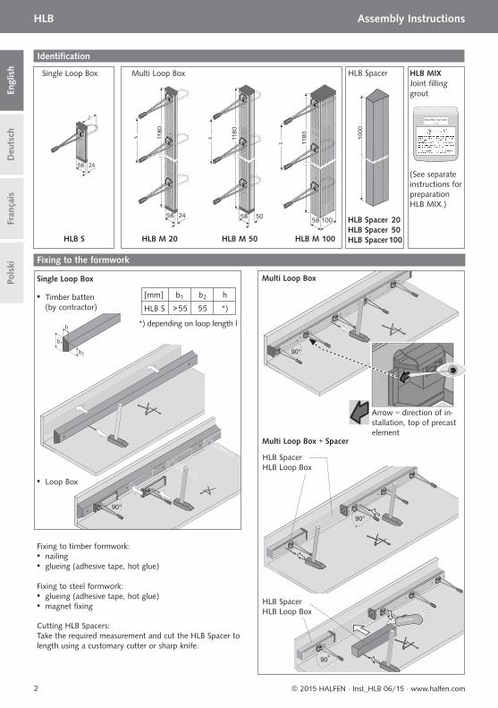
Identifi cation
HLB S
Single Loop Box
HLB M 20 HLB M 50 HLB M 100
Multi Loop Box
HLB Spacer 20HLB Spacer 50HLB Spacer 100
HLB Spacer
(See separate instructions for preparation HLB MIX.)
Joint fi lling grout
HLB MIX
Fixing to the formwork
Single Loop Box
Cutting HLB Spacers:Take the required measurement and cut the HLB Spacer to length using a customary cutter or sharp knife.
Fixing to timber formwork: ▪ nailing ▪ glueing (adhesive tape, hot glue)
Fixing to steel formwork: ▪ glueing (adhesive tape, hot glue) ▪ magnet fi xing
▪ Timber batten (by contractor)
▪ Loop Box
*) depending on loop length l
[mm] b1 b2 h
HLB S > 55 55 *)
HLB SpacerHLB Loop Box
HLB SpacerHLB Loop Box
Multi Loop Box
Multi Loop Box + Spacer
Arrow = direction of in-stallation, top of precast element
3© 2015 HALFEN · Inst_HLB 06/15 · www.halfen.com
HLB Assembly Instructions
Deu
tsch
Engl
ish
Fran
çais
Pols
ki
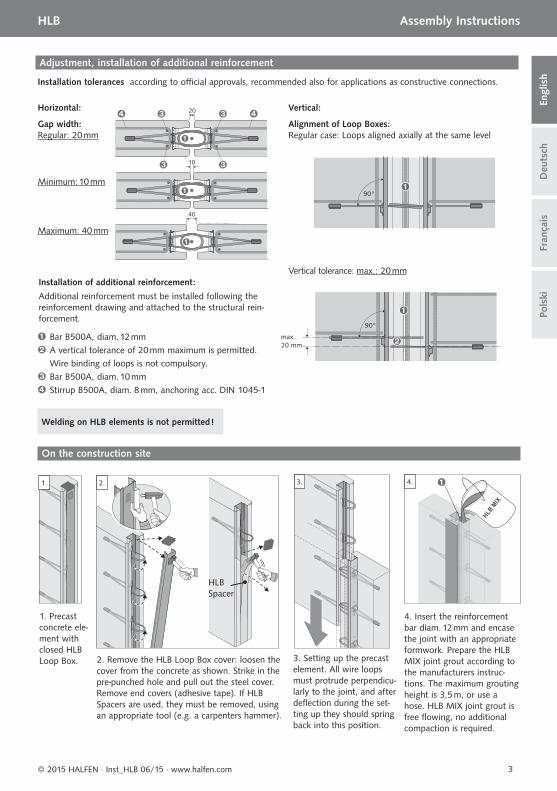
Adjustment, installation of additional reinforcement
Gap width: Regular: 20 mm
Alignment of Loop Boxes: Regular case: Loops aligned axially at the same level
Vertical tolerance: max.: 20 mm
Installation tolerances according to offi cial approvals, recommended also for applications as constructive connections.
Installation of additional reinforcement:
Additional reinforcement must be installed following the reinforcement drawing and attached to the structural rein-forcement.
Horizontal: Vertical:
Bar B500A, diam. 12 mmA vertical tolerance of 20 mm maximum is permitted. Wire binding of loops is not compulsory.Bar B500A, diam. 10 mmStirrup B500A, diam. 8 mm, anchoring acc. DIN 1045-1
Welding on HLB elements is not permitted !
Minimum: 10 mm
Maximum: 40 mm
1. 3. 4.
1. Precast concrete ele-ment with closed HLB Loop Box. 2. Remove the HLB Loop Box cover: loosen the
cover from the concrete as shown. Strike in the pre-punched hole and pull out the steel cover. Remove end covers (adhesive tape). If HLB Spacers are used, they must be removed, using an appropriate tool (e.g. a carpenters hammer).
3. Setting up the precast element. All wire loops must protrude perpendicu-larly to the joint, and after defl ection during the set-ting up they should spring back into this position.
4. Insert the reinforcement bar diam. 12 mm and encase the joint with an appropriate formwork. Prepare the HLB MIX joint grout according to the manufacturers instruc-tions. The maximum grouting height is 3,5 m, or use a hose. HLB MIX joint grout is free fl owing, no additional compaction is required.
2.
HLB Spacer
On the construction site
max.20 mm
4 © 2015 HALFEN · Inst_HLB 06/15 · www.halfen.com
HLB MontageanleitungD
euts
chEn
glis
hFr
ança
isPo
lski
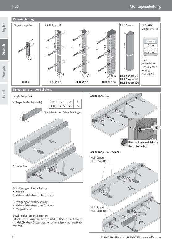
Kennzeichnung
HLB S
Single Loop Box
HLB M 20 HLB M 50 HLB M 100
Multi Loop Box
HLB Spacer 20HLB Spacer 50HLB Spacer 100
HLB Spacer
(Siehe gesonderte Gebrauchsan-leitung HLB MIX.)
VergussmörtelHLB MIX
Befestigung an der Schalung
Single Loop Box
Zuschneiden der HLB Spacer:Erforderliche Länge ausmessen und HLB Spacer mit einem handelsüblichen Cutter oder scharfen Messer auf Maß ab-trennen.
Befestigung an Holzschalung: ▪ Nageln ▪ Kleben (Klebeband, Heißkleber)
Befestigung an Stahlschalung: ▪ Kleben (Klebeband, Heißkleber) ▪ Magnethalter
▪ Trapezleiste (bauseits)
▪ Loop Box
*) abhängig von Schlaufenlänge l
[mm] b1 b2 h
HLB S > 55 55 *)
HLB SpacerHLB Loop Box
HLB SpacerHLB Loop Box
Multi Loop Box
Multi Loop Box + Spacer
Pfeil = Einbaurichtung Fertigteil oben
5© 2015 HALFEN · Inst_HLB 06/15 · www.halfen.com
HLB Montageanleitung
Deu
tsch
Engl
ish
Fran
çais
Pols
ki
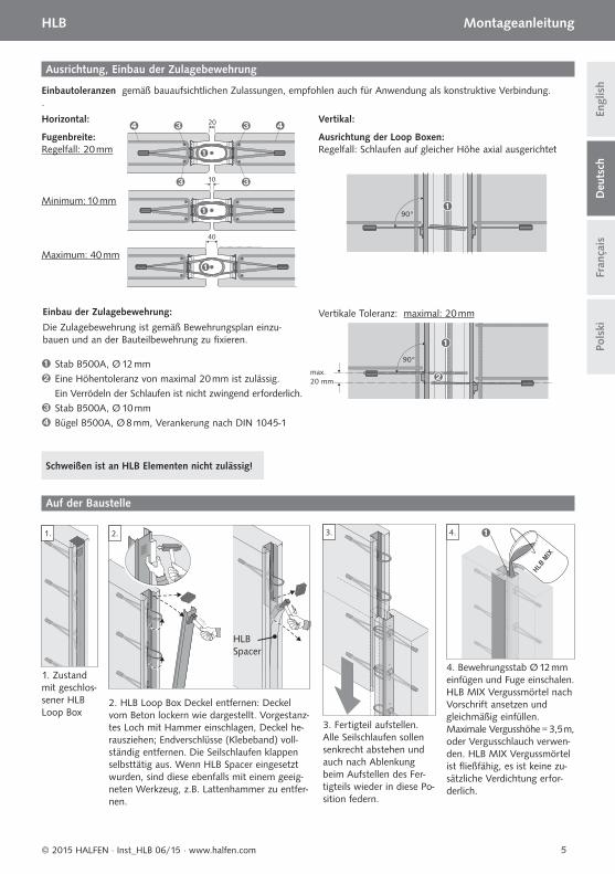
Ausrichtung, Einbau der Zulagebewehrung
Fugenbreite:Regelfall: 20 mm
Ausrichtung der Loop Boxen: Regelfall: Schlaufen auf gleicher Höhe axial ausgerichtet
Vertikale Toleranz: maximal: 20 mm
Einbautoleranzen gemäß bauaufsichtlichen Zulassungen, empfohlen auch für Anwendung als konstruktive Verbindung..
Einbau der Zulagebewehrung:
Die Zulagebewehrung ist gemäß Bewehrungsplan einzu-bauen und an der Bauteilbewehrung zu fi xieren.
Horizontal: Vertikal:
Stab B500A, Ø 12 mm Eine Höhentoleranz von maximal 20 mm ist zulässig. Ein Verrödeln der Schlaufen ist nicht zwingend erforderlich. Stab B500A, Ø 10 mmBügel B500A, Ø 8 mm, Verankerung nach DIN 1045-1
Schweißen ist an HLB Elementen nicht zulässig!
Minimum: 10 mm
Maximum: 40 mm
1.
1. Zustand mit geschlos-sener HLB Loop Box
3.
3. Fertigteil aufstellen. Alle Seilschlaufen sollen senkrecht abstehen und auch nach Ablenkung beim Aufstellen des Fer-tigteils wieder in diese Po-sition federn.
4.
4. Bewehrungsstab Ø 12 mm einfügen und Fuge einschalen. HLB MIX Vergussmörtel nach Vorschrift ansetzen und gleichmäßig einfüllen. Maximale Vergusshöhe = 3,5 m, oder Vergusschlauch verwen-den. HLB MIX Vergussmörtel ist fl ießfähig, es ist keine zu-sätzliche Verdichtung erfor-derlich.
2.
2. HLB Loop Box Deckel entfernen: Deckel vom Beton lockern wie dargestellt. Vorgestanz-tes Loch mit Hammer einschlagen, Deckel he-rausziehen; Endverschlüsse (Klebeband) voll-ständig entfernen. Die Seilschlaufen klappen selbsttätig aus. Wenn HLB Spacer eingesetzt wurden, sind diese ebenfalls mit einem geeig-neten Werkzeug, z.B. Lattenhammer zu entfer-nen.
HLB Spacer
Auf der Baustelle
max.20 mm
6 © 2015 HALFEN · Inst_HLB 06/15 · www.halfen.com
HLB Notice d‘utilisationD
euts
chEn
glis
hFr
ança
isPo
lski
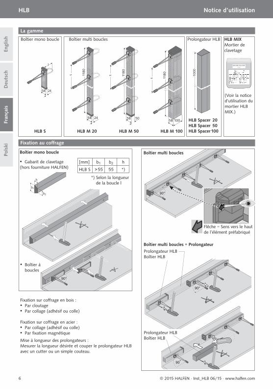
La gamme
HLB S
Boîtier mono boucle
HLB M 20 HLB M 50 HLB M 100
Boîtier multi boucles
HLB Spacer 20HLB Spacer 50HLB Spacer 100
Prolongateur HLB
(Voir la notice d‘utilisation du mortier HLB MIX.)
Mortier de clavetage
HLB MIX
Fixation au coff rage
Boîtier mono boucle
Mise à longueur des prolongateurs :Mesurer la longueur désirée et couper le prolongateur HLB avec un cutter ou un simple couteau.
Fixation sur coff rage en bois : ▪ Par cloutage ▪ Par collage (adhésif ou colle)
Fixation sur coff rage en acier : ▪ Par collage (adhésif ou colle) ▪ Par fi xation magnétique
▪ Gabarit de clavetage(hors fourniture HALFEN)
▪ Boîtier à boucles
*) Selon la longueur de la boucle l
[mm] b1 b2 h
HLB S > 55 55 *)
Prolongateur HLBBoîtier HLB
Prolongateur HLBBoîtier HLB
Boîtier multi boucles
Boîtier multi boucles + Prolongateur
Flêche = Sens vers le haut de l’élément préfabriqué
7© 2015 HALFEN · Inst_HLB 06/15 · www.halfen.com
HLB Notice d‘utilisation
Deu
tsch
Engl
ish
Fran
çais
Pols
ki
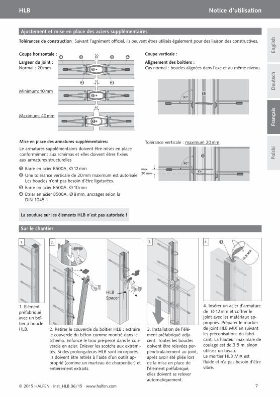
Ajustement et mise en place des aciers supplémentaires
Largeur du joint :Normal : 20 mm
Alignement des boîtiers : Cas normal : boucles alignées dans l‘axe et au même niveau.
Tolérance verticale : maximum 20 mm
Tolérances de construction Suivant l’agrément offi ciel, ils peuvent êtres utilisés également pour des liaison des constructives.
Mise en place des armatures supplémentaires:
Le armatures supplémentaires doivent être mises en place conformément aux schémas et elles doivent êtres fi xées aux armatures structurelles
Coupe horizontale : Coupe verticale :
Barre en acier B500A, Ø 12 mm Une tolérance verticale de 20 mm maximum est autorisée. Les boucles n’ont pas besoin d’être ligaturées. Barre en acier B500A, Ø 10 mmEtrier en acier B500A, Ø 8 mm, ancrages selon la DIN 1045-1
La soudure sur les élements HLB n’est pas autorisée !
Minimum: 10 mm
Maximum: 40 mm
1.
1. Elément préfabriqué avec un boî-tier à boucle HLB.
3.
3. Installation de l’élé-ment préfabriqué adja-cent. Toutes les boucles doivent être relevées per-pendiculairement au joint, après avoir été pliée lors de la mise en place de l’élément préfabriqué, elles doivent se relever automatiquement.
4.
4. Insérer un acier d’armature de Ø 12 mm et coff rer le joint avec les matériaux ap-propriés. Préparer le mortier de joint HLB MIX en suivant les préconisations du fabri-cant. La hauteur maximale de coulage est de 3,5 m, sinon utilisez un tuyau. Le mortier HLB MIX est fl uide et n’a pas besoin d’être vibré.
2.
2. Retirer le couvercle du boîtier HLB : extraire le couvercle du béton comme montré dans le schéma. Enfoncé le trou pré-percé dans le cou-vercle en acier. Enlever les scotchs aux extrémi-tés. Si des prolongateurs HLB sont incorporés, ils doivent être retirés à l’aide d’un outils ap-proprié (comme un marteau de charpentier) et entièrement extraits.
HLB Spacer
Sur le chantier
max.20 mm
8 © 2015 HALFEN · Inst_HLB 06/15 · www.halfen.com
HLB Instrukcja montażuD
euts
chEn
glis
hFr
ança
isPo
lski
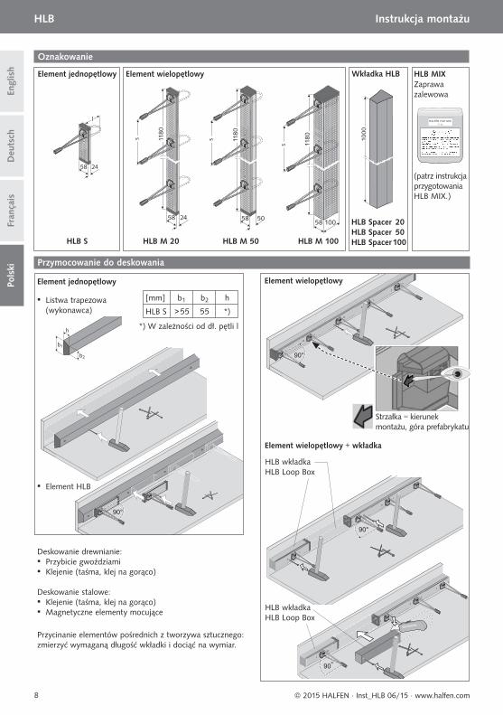
Oznakowanie
HLB S
Element jednopętlowy
HLB M 20 HLB M 50 HLB M 100
Element wielopętlowy
HLB Spacer 20HLB Spacer 50HLB Spacer 100
Wkładka HLB
(patrz instrukcja przygotowania HLB MIX.)
Zaprawa zalewowa
HLB MIX
Przymocowanie do deskowania
Element jednopętlowy
Przycinanie elementów pośrednich z tworzywa sztucznego:zmierzyć wymaganą długość wkładki i dociąć na wymiar.
Deskowanie drewnianie: ▪ Przybicie gwoździami ▪ Klejenie (taśma, klej na gorąco)
Deskowanie stalowe: ▪ Klejenie (taśma, klej na gorąco) ▪ Magnetyczne elementy mocujące
▪ Listwa trapezowa (wykonawca)
▪ Element HLB
*) W zależności od dł. pętli l
[mm] b1 b2 h
HLB S > 55 55 *)
HLB wkładkaHLB Loop Box
HLB wkładkaHLB Loop Box
Element wielopętlowy
Element wielopętlowy + wkładka
Strzałka = kierunek montażu, góra prefabrykatu
9© 2015 HALFEN · Inst_HLB 06/15 · www.halfen.com
HLB Instrukcja montażu
Deu
tsch
Engl
ish
Fran
çais
Pols
ki
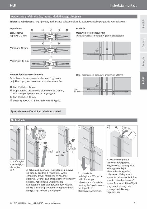
Ustawianie prefabrykatów, montaż dodatkowego zbrojenia
Szer. spoiny:Typowa: 20 mm
Ustawienie elementów HLB:Typowe: Ustawienie pętli w jednej płaszczyźnie
Dop. przesunięcie pionowe: maximum 20 mm
Tolerancja wbudowania wg Aprobaty Technicznej, zalecane także do zastosowań jako połączenia konstrukcyjne.
Montaż dodatkowego zbrojenia:
Dodatkowe zbrojenie należy wbudować zgodnie z projektem i przymocować do zbrojenia elementów.
w poziomie: w pionie:
Pręt B500A, Ø 12 mm Dopuszczalne przesunięcie pionowe max. 20 mm, Wiązanie pętli parami nie jest wymagane Pręt B500A, Ø 10 mmStrzemię B500A, Ø 8 mm, zakotwienie wg EC2
Spawanie elementów HLB jest niedopuszczalne!
Minimum: 10 mm
Maximum: 40 mm
1.
1. Prefabrykat z zamkniętym elementem HLB.
3.
3. Ustawienie prefabrykatu. Wszystkie pętle linowe po ustawieniu prefabrykatu powinny być usytuowane prostopadle do płaszczyzny połączenia.
4.
4. Wstawienie pręta i szalowanie połączenia. Przygotować zaprawę HLB MIX wg instrukcji i równomiernie wypełnić połączenie. Maksymalna wysokość betonowania 3,5 m, w razie potrzeby stosować rękaw. Zaprawa HLB MIX jest konystencji płynnej i nie wymaga dodatkowego zagęszczenia.
2. Usunięcie pokrywy HLB: odspoić pokrywę od betonu zgodnie z rysunkiem. Wybić oznaczony otwór młotkiem. Wyciągnąć pokrywę. Usunąć zamknięcia końcowe z taśmy klejącej. Pętle linowe wyprosują się samoczynnie. Jeśli wbudowane były wkładki, należy je usunąć przy pomocy odpowiednich narzędzi np. młotka ciesielskiego.
2.
HLB wkładka
Na budowie
max.20 mm

10 © 2015 HALFEN · Inst_HLB 06/15 · www.halfen.com
NOTES REGARDING THIS DOCUMENTTechnical and design changes reserved. The information in this publication is based on state-of-the-art technology at the time of publication. We reserve the right to make technical and design changes at any time. Halfen GmbH shall not accept liability for the accuracy of the information in this publication or for any printing errors.
The Quality Management System of Halfen GmbH is certifi ed for the locations in Germany, France, the Netherlands, Austria, Poland, Switzerland and the Czech Republic acc. to DIN EN ISO 9001:2008, Certifi cate No. QS-281 HH.
Furthermore HALFEN is represented with sales offi ces and distributors worldwide.
Austria HALFEN Gesellschaft m.b.H.Leonard-Bernstein-Str. 101220 Wien
Phone: +43 - 1 - 259 6770 E-Mail: offi [email protected]: www.halfen.at
Fax: +43 - 1 - 259 - 6770 99
Belgium /Luxembourg
HALFEN N.V.Borkelstraat 1312900 Schoten
Phone: +32 - 3 - 658 07 20E-Mail: [email protected]: www.halfen.be
Fax: +32 - 3 - 658 15 33
China HALFEN Construction Accessories Distribution Co.Ltd.Room 601 Tower D, Vantone CentreNo.A6 Chao Yang Men Wai StreetChaoyang District Beijing · P.R. China 100020
Phone: +86 - 10 5907 3200E-Mail: [email protected]: www.halfen.cn
Fax: +86 - 10 5907 3218
Czech Republic HALFEN s.r.o.Business Center ŠafránkovaŠafránkova 1238/1155 00 Praha 5
Phone: +420 - 311 - 690 060E-Mail: [email protected]: www.halfen-deha.cz
Fax: +420 - 235 - 314308
France HALFEN S.A.S.18, rue Goubet75019 Paris
Phone: +33 - 1 - 445231 00E-Mail: [email protected]: www.halfen.fr
Fax: +33 - 1 - 445231 52
Germany HALFEN Vertriebsgesellschaft mbHLiebigstr. 14 40764 Langenfeld
Phone: +49 - 2173 - 970 0E-Mail: [email protected]: www.halfen.de
Fax: +49 - 2173 - 970 225
Italy HALFEN S.r.l. Soc. UnipersonaleVia F.lli Bronzetti N° 2824124 Bergamo
Phone: +39 - 035 - 0760711E-Mail: [email protected]: www.halfen.it
Fax: +39 - 035 - 0760799
Netherlands HALFEN b.v.Oostermaat 37623 CS Borne
Phone: +31 - 74-267 14 49E-Mail: [email protected]: www.halfen.nl
Fax: +31 - 74-2 67 26 59
Norway HALFEN ASPostboks 20804095 Stavanger
Phone: +47 - 51 82 34 00E-Mail: [email protected]: www.halfen.no
Fax: +47 - 51 82 34 01
Poland HALFEN Sp. z o.o.Ul. Obornicka 28760-691 Poznan
Phone: +48 - 61 - 622 14 14E-Mail: [email protected]: www.halfen.pl
Fax: +48 - 61 - 622 14 15
Sweden Halfen ABVädursgatan 5412 50 Göteborg
Phone: +46 - 31 - 98 58 00E-Mail: [email protected]: www.halfen.se
Fax: +46 - 31 - 98 58 01
Switzerland HALFEN Swiss AGHertistrasse 25 8304 Wallisellen
Phone: +41 - 44 - 849 78 78E-Mail: [email protected]: www.halfen.ch
Fax: +41 - 44 - 849 78 79
United Kingdom /Ireland
HALFEN Ltd.A1/A2 Portland CloseHoughton Regis LU5 5AW
Phone: +44 - 1582 - 47 03 00E-Mail: [email protected]: www.halfen.co.uk
Fax: +44 - 1582 - 47 03 04
United States of America
HALFEN USA Inc.8521 FM 1976P.O. Box 547Converse, TX 78109
Phone: +1 800.423.91 40E-Mail: [email protected]: www.halfenusa.com
Fax: +1 877 . 683.4910
For countries not listed HALFEN International
HALFEN International GmbHLiebigstr. 14 40764 Langenfeld / Germany
Phone: +49 - 2173 - 970 - 0 E-Mail: [email protected]: www.halfen.com
Fax: +49 - 2173 - 970 - 849
CONTACT HALFEN WORLDWIDE
HALFEN is represented by subsidiar ies in the fol lowing 14 countr ies, please contact us:
Please contact us: www.halfen.com

© 2
015
HA
LFEN
Gm
bH, G
erm
any
appl
ies
also
to
copy
ing
in e
xtra
cts.
U -
306
- 06/
15
06/
1550
6