hitachi programmable automation controller series · (1) incorrect use as directed in this manual...
TRANSCRIPT

HITACHI PROGRAMMABLE AUTOMATION CONTROLLER
Series
APPLICATION MANUAL (Hardware) (SERVICE MANUAL)
NJI-637(X)

Warranty period and coverage
The warranty period is the shorter period either 18 months from the date of manufacture or 12 months from the date of installation. However even within the warranty period, the warranty will be void if the fault is due to; (1) Incorrect use as directed in this manual and / or in the application manual.
(2) Malfunction or failure caused by external device.
(3) Attempted repair by unauthorized personnel.
(4) Other force majeure, such as natural disasters, which beyond the responsibility of manufacturer.
The warranty is for the PAC only, any damage caused to third party equipment by malfunction of the PAC is not covered by the warranty.
Repair
Any investigation or repair after the warranty period cannot be covered as free of charge. Also any faults caused by above (1) to (4), will be charged for its repair (or for its investigation), even if the product is within the warranty period. In case of any contact, please ask your supplier or local Hitachi distributor. (Depending on failure part, investigation may not be possible to apply)
Ordering parts or asking questions
In case of repair, replacement parts ordering, or any other inquiries, please have the following details ready before contacting the place of purchase. (1) Model
(2) Manufacturing number (MFG.NO.)
(3) Details of the malfunction
Reader of this manual
This manual is described for the following person. ・Person considering to install PAC ・PAC system engineer ・Person handling PAC ・Person who maintain the installed PAC
Warning
(1) This manual may not be reproduced in its entirety or ant portion thereof without prior consent. (2) The content of this document may be changed without notice. (3) This document has been created with utmost care. However, if errors or questionable areas are found,
please contact us.
Windows is registered trademarks of America and other registered countries of Microsoft Corp. of the United States.
CODESYS is registered trademarks of 3S-Smart Software Solutions GmbH.
EtherCAT is registered trademark and patented technology, licensed by Beckhoff Automation GmbH, Germany.
Ethernet is registered trademarks of Fuji Xerox Co., Ltd.
Company name or a product name is trademark or a registered trademark.
Safety Precautions
Read this manual and related documents thoroughly before installing, operating, performing preventive maintenance or
performing inspection, and be sure to use the unit correctly. Use this product after acquiring adequate knowledge of the
unit, all safety information, and all cautionary information. Also, make sure this manual enters the possession of the
chief person in charge of safety maintenance.
Safety caution items are classifies as “Danger” and “Caution” in this document.
DANGER
: Cases where if handled incorrectly a dangerous circumstance may be created, resulting in
possible death or severe injury.
CAUTION
: Cases where if handled incorrectly a dangerous circumstance may be created, resulting in
possible minor to medium injury to the body, or only mechanical damage
However, depending on the circumstances, items marked with may result in major accidents.
In any case, they both contain important information, so please follow them closely.
Icons for prohibited items and required items are shown below:
: Indicates prohibited items (items that may not be performed). For example, when open flames are prohibited,
is shown.
: Indicates required items (items that must be performed). For example, when grounding must be performed,
is shown.
1. About installation
CAUTION
Use this product in an environment as described in the catalog and this document. If this product is used in an environment subject to high temperature, high humidity, excessive dust, corrosive gases, vibration or shock, it may result in electric shock, fire or malfunction.
Perform installation according to this manual. If installation is not performed adequately, it may result in dropping, malfunction or an operational error in the unit.
Do not allow foreign objects such as wire chips to enter the unit. They may become the cause of fire, malfunction or failure.
CAUTION

2. About wiring
REQUIRED
Always perform grounding (FE terminal). If grounding is not performed, there is a risk of electric shocks and malfunctions.
CAUTION
Connect power supply that meets rating. If a power supply that does not meet rating is connected, fire may be caused.
The wiring operation should be performed by a qualified personnel. If wiring is performed incorrectly, it may result in fire, damage, or electric shock.
3. Precautions when using the unit
DANGER
Do not touch the terminals while the power is on. There is a risk of electric shock.
Structure the emergency stop circuit, interlock circuit, etc. outside the programmable automation controller (hereinafter referred to as PAC). Damage to the equipment or accidents may occur due to failure of the PAC. However, do not interlock the unit to external load via relay drive power supply of the relay output module.
CAUTION
When performing program change, forced output, RUN, STOP, etc., while the unit is running, be sure to verify safety. Damage to the equipment or accidents may occur due to operation error.
Supply power according to the power–up order. Damage to the equipment or accidents may occur due to malfunctions.
CAUTION
Use power supply unit of EH series or HX series for supplying electric power.
CAUTION
Do not connect DC power supply module EH-PSD to a master power circuit. Supply a power to EH-PSD through an appropriate isolation transformer less than up to 150 VA by all means.

4. About preventive maintenance
DANGER
Do not connect the +, - of the battery in reverse. Also, do not charge, disassemble, heat, place in fire, or short circuit the battery. There is a risk of explosion or fire.
PROHIBITED
Do not disassemble or modify the unit. Electric shock, malfunction or failure may result.
CAUTION
Turn off the power supply before removing or attaching module/unit. Electric shock, malfunction or failure may result.

Revision History
No. Description of revision Date of revision
Manual number
1 The first edition 2016.11 NJI-637(X)

Table of Contents
Chapter 1 Introduction 1-1 to 1-4
1.1 Doing after Unpacking .................................................................................................................. 1-1 1.2 About Manuals .............................................................................................................................. 1-2
Chapter 2 Features 2-1 to 2-10
2.1 Features of HX Series ................................................................................................................... 2-1 2.2 Integrated Development System HX-CODESYS .......................................................................... 2-5 2.3 Communication Function .............................................................................................................. 2-9 2.4 System Configuration .................................................................................................................... 2-10
Chapter 3 General Specifications 3-1 to 3-6
3.1 General Specifications .................................................................................................................. 3-1 3.2 List of System Equipment ............................................................................................................. 3-2 3.3 List of Current Consumption ......................................................................................................... 3-6
Chapter 4 CPU Module 4-1 to 4-14
4.1 Outline ........................................................................................................................................... 4-1 4.2 Performance Specifications .......................................................................................................... 4-5 4.3 Ethernet Port Specifications .......................................................................................................... 4-8 4.4 USB Port Specifications ................................................................................................................ 4-10 4.5 SD Card Specifications ................................................................................................................. 4-11 4.6 Serial Port Specifications .............................................................................................................. 4-12 4.7 Battery Specifications ................................................................................................................... 4-13
Chapter 5 Power Supply, Base, I/O Controller 5-1 to 5-8
5.1 Power Supply Module ................................................................................................................... 5-1 5.2 Base Unit....................................................................................................................................... 5-5 5.3 I/O Controller ................................................................................................................................. 5-8
Chapter 6 Digital I/O Module 6-1 to 6-34
6.1 Outline ........................................................................................................................................... 6-1 6.2 Specifications ................................................................................................................................ 6-4
Chapter 7 Analog I/O Module, Resistance Temperature Detector Input Module, Thermocouple Input Module 7-1 to 7-30
7.1 12-bit Analog I/O Module .............................................................................................................. 7-1 7.2 14-bit Analog I/O Module .............................................................................................................. 7-12 7.3 Isolated Analog I/O Module ........................................................................................................... 7-17 7.4 Resistance Temperature Detector Input Module .......................................................................... 7-22 7.5 Thermocouple Input Module ......................................................................................................... 7-27
Chapter 8 Positioning and Counter Module 8-1 to 8-8
8.1 Single-axis Positioning Module ..................................................................................................... 8-1 8.2 High Speed Counter Module ......................................................................................................... 8-4

Chapter 9 Communication and Network Module 9-1 to 9-20
9.1 CPU Link Module .......................................................................................................................... 9-1 9.2 PROFIBUS-DP Master Module 2 .................................................................................................. 9-4 9.3 PROFIBUS-DP Slave Controller 2 ................................................................................................ 9-9 9.4 EtherCAT Slave Controller ............................................................................................................ 9-13 9.5 FL-net Module 3 ............................................................................................................................ 9-17
Chapter 10 Accessories 10-1 to 10-6
10.1 Dummy Module ............................................................................................................................. 10-1 10.2 Expansion Cable ........................................................................................................................... 10-1 10.3 Terminal Block for 32/64 Points I/O Module ................................................................................. 10-2 10.4 Cable for 32 / 64-Point Module ..................................................................................................... 10-4 10.5 Cable for Counter Input Module .................................................................................................... 10-5
Chapter 11 PAC Installation, Mounting, Wiring 11-1 to 11-10
11.1 Installation ..................................................................................................................................... 11-1 11.2 Mounting Module ........................................................................................................................... 11-3 11.3 Wiring ............................................................................................................................................ 11-4
Chapter 12 Maintenance and Inspection 12-1 to 12-2
12.1 Daily and Periodic Inspection ........................................................................................................ 12-1 12.2 Life of Product ............................................................................................................................... 12-2
Chapter 13 Troubleshooting 13-1 to 13-6
13.1 Error Code .................................................................................................................................... 13-1 13.2 Corrective Actions when Error Occurs .......................................................................................... 13-4 13.3 Error Libraries .............................................................................................................................. 13-6

1 – 1
Chapter 1 Introduction Thank you very much for choosing Hitachi Programmable Automation Controller (hereinafter referred to as PAC) HX
series.
This application manual informs hardware of HX series which is a high-performance PAC system suitable for IoT.
The contents relevant to programming has been separated as an application manual (software) and a command
reference manual.
Please read this manual and the following manuals carefully when constructing a system using HX series.
Table 1.1 List of Description materials
Items Title of material Manual number
HX series Application manual (Hardware) NJI-637*1(X) Application manual (Software) NJI-638*1(X) Command reference manual NJI-639*1(X)
*1 The last alphabet of the manual No. stands for version starting from blank, A, B, C...
1.1 Doing after Unpacking
(1) Preparation of programming software HX-CODESYS
The programming software HX-CODESYS more than Ver3.5 SP8 Patch4 is necessary to use HX series CPU module
(hereinafter referred to as HX-CPU).
Because programming software EHV-CODESYS for the Hitachi programmable controller EHV+ series does not
support HX-CPU module, please do not use it.
(2) Initializing of user program
Since a memory in the HX-CPU is not set at first, error code to mean memory error may be displayed on the
7-segment LED. Please initialize the memory in the HX-CPU first by using HX-CODESYS.
(3) Battery error indication
HX-CPU is shipped without a lithium battery. The battery is sold separately from CPU.
Therefore when Battery error detection*2 (OK LED blinking in the battery error) of HX-CODESYS is set Enable,
HX-CPU detects a battery error, and "71" is displayed in 7-segment LED. When you want to invalidate battery error
detection, please set this parameter in Disable (invalidity).
*2 The tab of Configuration in Device of the project tree has the setting of Battery error detection.
Battery error detection is set in Enable in initial setup.

Chapter 1 Introduction
1 – 2
1.2 About Manuals
Various modules for EH-150 / EHV series shown in Table 1.2 are able to be used with HX-CPU. There is some
module that HX-CPU does not support yet. Un-supported modules are going to be supported.
Please refer to manuals shown in Table 1.2 for the detail specification of various modules. Please refer to chapter 5 or
after of this manual for modules which manual number are blank in Table 1.2.
Table 1.2 Related manuals to HX-CPU (1/2)
Product name
Model name Specifications
Manual number Japanese English
Power supply module
EH-PSA Input 100 to 240 V AC Output - - EH-PSD Input 21.6 to 26.4 V DC Output - - EH-PSR Input 100 to 240 V AC Output for redundancy - -
I/O controller EH-IOCH2 I/O controller for expansion unit - - Digital input module
EH-XD8 8 points, 24 V DC input - - EH-XD16 16 points, 24 V DC input - - EH-XDL16 16 points, 24 V DC input, Intensified filter - - EH-XDS16 16 points, 24 V DC Fast input - - EH-XD32 32 points, 24 V DC input - - EH-XDL32 32 points, 24 V DC input, Intensified filter - - EH-XDS32 32 points, 24 V DC Fast input - - EH-XD32E 32 points, 24 V DC input, Spring type terminal block - - EH-XDL32E 32 points, 24 V DC input, Spring type terminal block, Intensified filter - - EH-XD32H 32 points, 24 V DC input, Compatible connecter with EM and H-200 - - EH-XD64 64 points, 24 V DC input - - EH-XA16 16 points, 100 to 120 V AC input - - EH-XAH16 16 points, 200 to 240 V AC input - -
Digital output module
EH-YR8B 8 points, relay output (isolated contact point), 100 / 240VAC, 24V DC - - EH-YR12 12 points, relay output, 100 / 240 V AC, 24 V DC - - EH-YR16 16 points, relay output, 100 / 240 V AC, 24 V DC, 16 points / 1 common - - EH-YR16D 16 points, relay output, 100 / 240 V AC, 24 V DC, 8 points / 1 common - - EH-YT8 8 points, transistor output, 12 / 24 V DC (sink type) - - EH-YTP8 8 points, transistor output, 12 / 24 V DC (source type) - - EH-YT16 16 points, transistor output, 12 / 24 V DC (sink type) - - EH-YTP16 16 points, transistor output, 12 / 24 V DC (source type) - - EH-YTP16S 16 points, transistor output, 12 / 24 V DC (source type),
short-circuit protection - -
EH-YT32 32 points, transistor output, 12 / 24 V DC (sink type) - - EH-YTP32 32 points, transistor output, 12 / 24 V DC (source type) - -
EH-YT32E 32 points, transistor output, 12 / 24 V DC (sink type) Spring terminal block - -
EH-YTP32E 32 points, transistor output, 12 / 24 V DC (source type) Spring terminal block - -
EH-YT32H 32 points, transistor output, 5 / 12 / 24 V DC (sink type) Compatible connecter with EM and H-200 - -
EH-YT64 64 points, transistor output, 12 / 24 V DC (sink type) - - EH-YTP64 64 points, transistor output, 12 / 24 V DC (source type) - - EH-YS16 16 points, triac output, 100 / 240 V AC - -
* The last alphabet of the manual No. stands for version starting from blank, A, B, C...

Chapter 1 Introduction
1 – 3
Table 1.2 Related manuals to HX-CPU (2/2)
Product name Model name Specifications Manual number
Japanese English Analog input module
EH-AX44 12 bits analog input (4 to 20 mA, 0 to 10 V) each 4 ch. - - EH-AX8V 12 bits analog input 8 ch., Voltage (0 to +10 V) - - EH-AX8H 12 bits analog input 8 ch., Voltage (-10 to +10 V) - - EH-AX8I 12 bits analog input 8 ch., Current (4 to 20 mA) - - EH-AX8IO 12 bits analog input 8 ch., Current (0 to 22 mA) - -
EH-AXH8M 14 bits analog input 8 ch. (0 to 22 mA, 4 to 22 mA, -10 to +10 V, 0 to 10 V) - -
EH-AXG5M Isolation between channels, 16 bits analog input 5ch. (0 to 22 mA, 4 to 22 mA, -10 to +10 V, 0 to 10 V) - -
Analog output module
EH-AY22 12 bits analog output (4 to 20 mA, 0 to 10 V) each 2 ch. - - EH-AY2H 12 bits analog output 2 ch., Voltage (-10 to +10 V) - - EH-AY4V 12 bits analog output 4 ch., Voltage (0 to +10 V) - - EH-AY4H 12 bits analog output 4 ch., Voltage (-10 to +10 V) - - EH-AY4I 12 bits analog output 4 ch., Current (4 to 20 mA) - - EH-AYH8M 14 bits analog output 8 ch., (0 to 22 mA, 4 to 22 mA, 0 to 10 V) - - EH-AYG4M Isolation between channels, 16 bits analog output 4 ch.
(0 to 22 mA, 4 to 22 mA, -10 to +10 V, 0 to 10 V) - -
RTD input module EH-PT4
4 channels resistance temperature detector, Signed 15 bits Platinum (Pt 100 Ω / Pt 1000 Ω) NJI-323* NJI-324*(X)
EH-RTD8 6/8 channels resistance temperature detector, Signed 15 bits Platinum (Pt 100 Ω / Pt 1000 Ω) - -
Thermocouple input module EH-TC8
Signed 15 bits, Thermocouple input (K, E, J, T, B, R, S, N) 8 channels - -
Positioning and counter module EH-CU
2 channels high-speed counter input, Maximum frequency of 100 kHz, 1/2-phases switchover, 4-point opened collector output NJI-321* NJI-321*(X)
EH-CUE 1 channel high-speed counter input, Maximum frequency of 100 kHz, 1/2-phases switchover, 2-point opened collector output - -
EH-POS 1-axis pulse positioning module NJI-314* NJI-315*(X) Communication module
EH-RMP2 PROFIBUS-DP master module, 512 / 512 words I/O, 8 units per CPU can be installed NJI-621* NJI-621*(X)
EH-IOCP2 PROFIBUS-DP slave controller, 122 / 122 words I/O NJI-612* NJI-612*(X)
EH-IOCA EtherCAT slave controller, 176 words I/O NJI-599* NJI-599*(X) EH-FLN3 FL-net interface module NJI-410* - EH-LNK CPU link module (coaxial), 8 units per CPU can be mounted NJI-381* NJI-381*(X) EH-OLNK CPU link module (optical fiber), 8 units per CPU can be mounted NJI-395* NJI-395*(X) EH-OLNKG CPU link module (support optical fiber GI50 / 125 µm cable),
8 units per CPU can be mounted NJI-395* NJI-395*(X)
EH-OLNKE CPU link module (support optical fiver GI62.5 / 125 µm cable), 8 units per CPU can be mounted NJI-395* NJI-395*(X)
* The last alphabet of the manual No. stands for version starting from blank, A, B, C...

Chapter 1 Introduction
1 – 4
MEMO

2 – 1
Chapter 2 Features 2.1 Features of HX Series
Open standards, High-performance, TCO reduction*1 (1) Open standards
The Hitachi HX Series supports global manufacturing by standardized programming with
5 programming languages compatible with the IEC61131-3 international standard. The integrated EtherCAT master
function (industrial open network) enables interconnection of a wide range of devices. Seamless data transfer from
field level to cloud is achieved via OPC-Unified Architecture.
(2) High-performance
Through the effective combination of up-to-date developed high-performance CPU with CODESYS software, Hitachi
provides sequential control (logic) and motion control*3 on one CPU platform with very fast execution speed.
(3) TCO reduction*1
HX Series are designed to provide the functionality of PAC Controller (Programmable Automation Controller) which
has both features of PLC and IPC.
HX series contribute to TCO (Total cost of ownership) reduction by drive down cost of installation, development and
maintenance.
ERP : Enterprise Resource Planning, MES : Manufacturing Execution System
WMS : Warehouse Management System, IPC : Industrial PC
PLC : Programmable Logic Controller
*1 Total Cost of Ownership
*2 HF-W / IoT is a product of Hitachi Industry and Control Solutions, Ltd.
*3 Motion model is available with PLCopen based motion control function block. This model is planned to be
released in near future.
MES WMS
ERP ERP
Network
Cloud
Data
Order
Enterprise Management
Operation
Supervision Control
Field Sensors
Seamless connectivity
Machines Devices
IPC based
I oT PAC system
Controller
HF-W/IoT *2
PLC PLC
HX serirs
Logic control
Communication
Soft motion
Supporting various field networks
3 Ethernet port as standard (Full function model)
Various communication modes between master, controller and slave units by one CPU.
*3
Chapter 2 Features
2 – 2
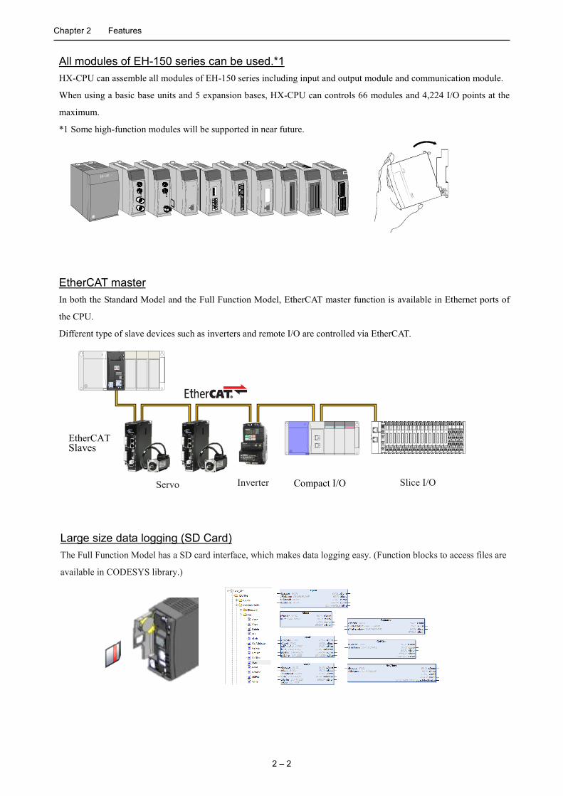
All modules of EH-150 series can be used.*1 HX-CPU can assemble all modules of EH-150 series including input and output module and communication module.
When using a basic base units and 5 expansion bases, HX-CPU can controls 66 modules and 4,224 I/O points at the
maximum.
*1 Some high-function modules will be supported in near future.
3 2 1 0 7 6 5 4 1
1
9 8 1
1
1
1
3 2 1 0 7 6 5 4 1
1
9 8 1
1
1
1
EtherCAT master In both the Standard Model and the Full Function Model, EtherCAT master function is available in Ethernet ports of
the CPU.
Different type of slave devices such as inverters and remote I/O are controlled via EtherCAT.
EtherCAT Slaves
Compact I/O Inverter Servo Slice I/O
Large size data logging (SD Card) The Full Function Model has a SD card interface, which makes data logging easy. (Function blocks to access files are
available in CODESYS library.)
Chapter 2 Features
2 – 3
OPC UA Server The OPC UA (Unified Architecture) is a software interface between different manufacturers’ apparatuses and host
system based on the concept to unify industrial field and IT field.
HX-CPU has OPC-UA server function as standard. OPC-UA server allows easy connectivity with ERP, MES,
SCADA, SAP, and various management and analysis software in host system.
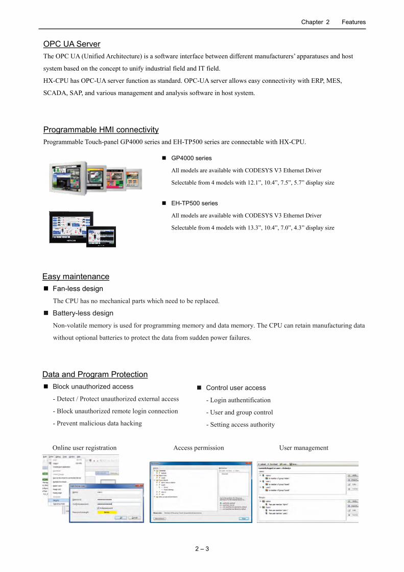
Programmable HMI connectivity Programmable Touch-panel GP4000 series and EH-TP500 series are connectable with HX-CPU.
Easy maintenance Fan-less design
The CPU has no mechanical parts which need to be replaced.
Battery-less design
Non-volatile memory is used for programming memory and data memory. The CPU can retain manufacturing data
without optional batteries to protect the data from sudden power failures.
Data and Program Protection Block unauthorized access
- Detect / Protect unauthorized external access
- Block unauthorized remote login connection
- Prevent malicious data hacking
Online user registration Access permission User management
GP4000 series
All models are available with CODESYS V3 Ethernet Driver
Selectable from 4 models with 12.1”, 10.4”, 7.5”, 5.7” display size
EH-TP500 series
All models are available with CODESYS V3 Ethernet Driver
Selectable from 4 models with 13.3”, 10.4”, 7.0”, 4.3” display size
Control user access
- Login authentification
- User and group control
- Setting access authority
Chapter 2 Features
2 – 4
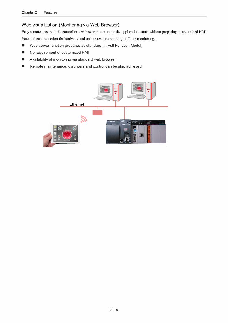
Web visualization (Monitoring via Web Browser) Easy remote access to the controller´s web server to monitor the application status without preparing a customized HMI.
Potential cost reduction for hardware and on site resources through off site monitoring.
Web server function prepared as standard (in Full Function Model)
No requirement of customized HMI
Availability of monitoring via standard web browser
Remote maintenance, diagnosis and control can be also achieved
Ethernet

Chapter 2 Features
2 – 5
2.2 Integrated Development System HX-CODESYS
CODESYS is the widest-spread IEC61131-3 development system in the world. Over 350 controller manufacturers rely
on CODESYS, in addition to tens of thousands of end users from a wide variety of industries.
HX-CODESYS -integrating various support functions in every phase of development
Project tree allow you collective management of device, task and program of application.
Integrated configurator for EtherCAT and Modbus can connect I/O channels on slaves to IEC variables.
HX-CODESYS is including editors for all 5 IEC 61131-3 compliant implementation languages.
The tool display language supports Japanese, English German, French, Italian, Spanish, Russian,
Chinese, eight languages in total.
Optional object-oriented programming according to IEC 61131-3 (3rd Edition).
Compiler for optimized powerful machine code of HX-CPU.
Various function such as automatic input completion and assistance, syntax error check, debug and
simulation allow you efficient development.

Chapter 2 Features
2 – 6
IEC61131-3 compliant 5 languages available to skill and application
LD (Ladder Diagram) LD is a graphical language based on relay circuit. LD is suitable for the bit operation such as interlock processes.
FBD (Function Block Diagram) FBD is a graphic language which the flow of data and the signal is easy to watch.
ST (Structured Text) ST is a text language based on PASCAL. It is suitable for branch, repetition and the arithmetic operation that were weak points in LD.
IL (Instruction List) IL is a text language suitable for traditional PLC. It is suitable for high speed operation and convenient for read out and collate program.
SFC (Sequential Function Chart) SFC is a graphic language which can express state transition. It is suitable for process control to step. Each step is able to be described with LD, FBD and IL.
CFC (Continuous Function Chart) CFC is a graphical language with unrestricted layout of POUs and connections, including feedback paths. (CFC is not IEC61131-3 compliant language.)

Chapter 2 Features
2 – 7
Reduction of development time and cost of IEC 61131-3 compliant applications
Local variable and Global variable
You can define Local variables that are effective only in each program and Global variables that are effective in
all program. You can make application program having high reusability by using a local variable and global
variable properly.
Structured programming
You can make programs and function blocks with multi-layer structure. This structured programming improves
readability of program, maintenance characteristics and reliability. As a result, application development efficiency
increases.
Library
Frequently used program or function can be registered as library, which can be called from other projects. Library
contents can able to be non-indicated for the distribution use to end users.
Substantial library Various libraries such as PID or various conversion are incorporated as a standard library other than IEC61131-3
standard command.
PID
Analog output with Slew Rate
ASCII conversion
BCD conversion
Gray code conversion
String operation
Analog hysteresis
Minimum, Maximum, Mean,
Variance
Trial run Debug Programming System design
Reduction

Chapter 2 Features
2 – 8
Convenient functions HX-CODESYS improves programming efficiency, debug efficiency in various convenient functions.
Automatic input completion and assistance avoiding compile error because of input error.
Color-coded syntax highlighting, for example keywords and connected brackets.
In LD editor and FBD editor, you can use ST language in function block.
You can change any circuit or command to comment with right-click.
Powerful debugging functions Powerful debugging functions features save commissioning cost.
Online-monitor
Offline-simulation
Breakpoint
Force value
Single step execution
Single cycle execution
Flow control
Program change during run
Trace
Visualization
Web visualization
About HX-CODESYS
HX-CODESYS is IEC61131-3 compliant integrated development system for only HX series.
CODESYS® is a registered trademark of 3S-Smart Software Solutions GmbH. HX-CODESYS is the same tool with
CODESYS, but is preinstalled device description files and libraries for HX series.

Chapter 2 Features
2 – 9
2.3 Communication Function
HX-CPU of Full function model has 3 Ethernet ports.(HX-CPU of standard model has 2 Ethernet ports) HX-CPU can
communicate with host system, controller, and field devices individually. In addition, by a combination of how to use,
HX-CPU can realize various communications.
Figure 2.1 Ethernet Communication port
You can build a flexible system with HX-CPU and Hitachi EtherCAT slave products such as coupler type slave
(EH-IOCA) and Inverter and Servo. EH-IOCA is a coupler type slave and can be connected with 22 modules per slave
node. Therefore, EH-IOCA can control 1,408 points in digital I/O. (176 channels in analog I/O) The configuration
example is shown in Figure 2.2.
[Configuration Example]
EtherCAT master (HX-CPU)
EH-IOCA
LAN cable (More over CAT5, maximum 100m between slaves)
EH-IOCA
Slave Slave
I/O controller EH-IOCH2
Redundant power supply
Slave controller EH-IOCA
Configuration with redundant power supply is possible.
You can increase I/O points with
adding Expansion base unit.
ADV series
WJ200 series
Servo amplifier and Motor ADV series HTW motor series
Inverter WJ200 series
Figure 2.2 EtherCAT configuration
Ethernet
Ethernet
OPC-UA
Cloud
Host system
Communication toward 3 direction
Chapter 2 Features
2 – 10
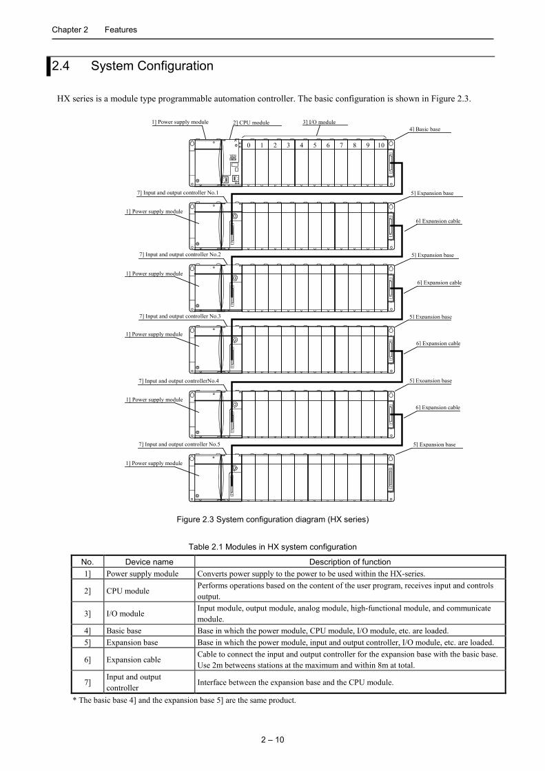
2.4 System Configuration
HX series is a module type programmable automation controller. The basic configuration is shown in Figure 2.3.
1] Power supply module 2] CPU module 3] I/O module
0 1 2 3 4 5 6 7 8 9 10
7] Input and output controller No.1
7] Input and output controller No.2
7] Input and output controller No.3
7] Input and output controllerNo.4
5] Expansion base
6] Expansion cable
5] Expansion base
6] Expansion cable
5] Expansion base
6] Expansion cable
5] Exoansion base
4] Basic base
1] Power supply module
1] Power supply module
1] Power supply module
1] Power supply module
1] Power supply module
7] Input and output controller No.5 5] Expansion base
6] Expansion cable
Figure 2.3 System configuration diagram (HX series)
Table 2.1 Modules in HX system configuration
No. Device name Description of function 1] Power supply module Converts power supply to the power to be used within the HX-series.
2] CPU module Performs operations based on the content of the user program, receives input and controls output.
3] I/O module Input module, output module, analog module, high-functional module, and communicate module.
4] Basic base Base in which the power module, CPU module, I/O module, etc. are loaded. 5] Expansion base Base in which the power module, input and output controller, I/O module, etc. are loaded.
6] Expansion cable Cable to connect the input and output controller for the expansion base with the basic base. Use 2m betweens stations at the maximum and within 8m at total.
7] Input and output controller
Interface between the expansion base and the CPU module.
* The basic base 4] and the expansion base 5] are the same product.
3 – 1
Chapter 3 General Specifications
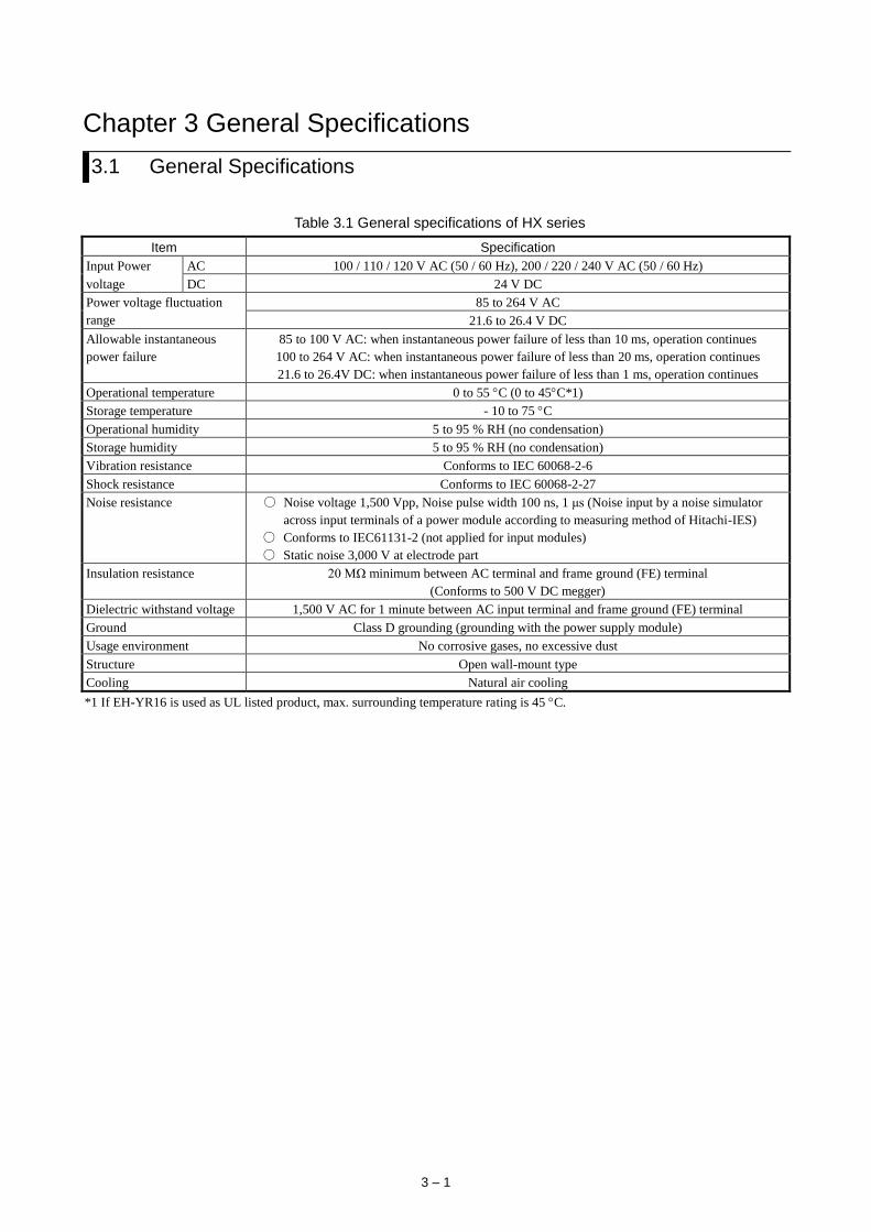
3.1 General Specifications
Table 3.1 General specifications of HX series
Item Specification
Input Power AC 100 / 110 / 120 V AC (50 / 60 Hz), 200 / 220 / 240 V AC (50 / 60 Hz)
voltage DC 24 V DC
Power voltage fluctuation
range
85 to 264 V AC
21.6 to 26.4 V DC
Allowable instantaneous
power failure
85 to 100 V AC: when instantaneous power failure of less than 10 ms, operation continues
100 to 264 V AC: when instantaneous power failure of less than 20 ms, operation continues
21.6 to 26.4V DC: when instantaneous power failure of less than 1 ms, operation continues
Operational temperature 0 to 55 C (0 to 45C*1)
Storage temperature - 10 to 75 C
Operational humidity 5 to 95 % RH (no condensation)
Storage humidity 5 to 95 % RH (no condensation)
Vibration resistance Conforms to IEC 60068-2-6
Shock resistance Conforms to IEC 60068-2-27
Noise resistance Noise voltage 1,500 Vpp, Noise pulse width 100 ns, 1 μs (Noise input by a noise simulator
across input terminals of a power module according to measuring method of Hitachi-IES)
Conforms to IEC61131-2 (not applied for input modules)
Static noise 3,000 V at electrode part
Insulation resistance 20 MΩ minimum between AC terminal and frame ground (FE) terminal
(Conforms to 500 V DC megger)
Dielectric withstand voltage 1,500 V AC for 1 minute between AC input terminal and frame ground (FE) terminal
Ground Class D grounding (grounding with the power supply module)
Usage environment No corrosive gases, no excessive dust
Structure Open wall-mount type
Cooling Natural air cooling
*1 If EH-YR16 is used as UL listed product, max. surrounding temperature rating is 45 C.
Chapter 3 General Specifications
3 – 2
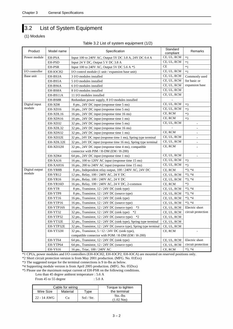
3.2 List of System Equipment
(1) Modules
Table 3.2 List of system equipment (1/2)
Product Model name Specification Standard compliant
Remarks
Power module EH-PSA Input 100 to 240V AC, Output 5V DC 3.8 A, 24V DC 0.4 A CE, UL, RCM *1
EH-PSD Input 24 V DC, Output 5 V DC 3.8 A CE, UL, RCM *1
EH-PSR Input 100 to 240V AC, Output 5V DC 5.6 A *5 CE *1
I/O controller EH-IOCH2 I/O control module (1 unit / expansion base unit) CE, UL, RCM *1
Base unit EH-BS3A 3 I/O modules installed CE, UL, RCM Commonly used
for basic or
expansion base
EH-BS5A 5 I/O modules installed CE, UL, RCM
EH-BS6A 6 I/O modules installed CE, UL, RCM
EH-BS8A 8 I/O modules installed CE, UL, RCM
EH-BS11A 11 I/O modules installed CE, UL, RCM
EH-BS8R Redundant power supply, 8 I/O modules installed -
Digital input
module EH-XD8 8 pts., 24V DC input (response time 5 ms) CE, UL, RCM *3
EH-XD16 16 pts., 24V DC input (response time 5 ms) CE, UL, RCM *3
EH-XDL16 16 pts., 24V DC input (response time 16 ms) CE, RCM *3
EH-XDS16 16 pts., 24V DC input (response time 1 ms) CE, RCM *3
EH-XD32 32 pts., 24V DC input (response time 5 ms) CE, UL, RCM -
EH-XDL32 32 pts., 24V DC input (response time 16 ms) - -
EH-XDS32 32 pts., 24V DC input (response time 1 ms) CE, RCM -
EH-XD32E 32 pts., 24V DC input (response time 1 ms), Spring type terminal CE, UL, RCM -
EH-XDL32E 32 pts., 24V DC input (response time 16 ms), Spring type terminal CE, UL, RCM -
EH-XD32H 32 pts., 24V DC input (response time 4 ms), compatible
connector with PIM / H-DM (EM / H-200)
CE, RCM -
EH-XD64 64 pts., 24V DC input (response time 1 ms) CE, UL, RCM -
EH-XA16 16 pts., 100 to 120V AC input (response time 15 ms) CE, UL, RCM *3
EH-XAH16 16 pts., 200 to 240V AC input (response time 15 ms) CE, UL, RCM *3
Digital output
module EH-YR8B 8 pts., Independent relay output, 100 / 240V AC, 24V DC CE, RCM *3, *4
EH-YR12 12 pts., Relay, 100 / 240V AC, 24 V DC CE, UL, RCM *3, *4
EH-YR16 16 pts., Relay, 100 / 240V AC, 24 V DC CE, UL, RCM *3, *4
EH-YR16D 16 pts., Relay, 100 / 240V AC, 24 V DC, 2-common CE, RCM *3
EH-YT8 8 pts., Transistor, 12 / 24V DC (sink type) CE, UL, RCM *3, *4
EH-YTP8 8 pts., Transistor, 12 / 24V DC (source type) CE, UL, RCM *3, *4
EH-YT16 16 pts., Transistor, 12 / 24V DC (sink type) CE, UL, RCM *3, *4
EH-YTP16 16 pts., Transistor, 12 / 24V DC (source type) CE, UL, RCM *3, *4
EH-YTP16S 16 pts., Transistor, 12 / 24V DC (source type) *3 CE, UL, RCM Electric short
circuit protection
EH-YT32 32 pts., Transistor, 12 / 24V DC (sink type) *2 CE, UL, RCM
EH-YTP32 32 pts., Transistor, 12 / 24V DC (source type) *2 CE, UL, RCM
EH-YT32E 32 pts., Transistor, 12 / 24V DC (sink type), Spring type terminal CE, UL, RCM
EH-YTP32E 32 pts., Transistor, 12 / 24V DC (source type), Spring type terminal CE, UL, RCM
EH-YT32H 32 pts., Transistor, 5 / 12 / 24V DC (sink type),
compatible connector with POM / H-DM (EM / H-200)
CE, RCM -
EH-YT64 64 pts., Transistor, 12 / 24V DC (sink type) CE, UL, RCM Electric short
circuit protection
EH-YTP64 64 pts., Transistor, 12 / 24V DC (source type) CE, UL, RCM
EH-YS16 16 pts., Triac, 100 / 240V AC CE, RCM *3, *4
*1 CPUs, power modules and I/O controllers (EH-IOCH2, EH-IOCP2, EH-IOCA) are mounted on reserved positions only.
*2 Short circuit protection version is from May 2001 production. (MFG. No. 01Exx)
*3 The suggested torque for the terminal connections is 9 in-lbs as below.
*4 Supporting module version is from April 2005 production. (MFG. No. 05Dxx)
*5 Please use the maximum output current of EH-PSR on the following conditions.
Less than 45 degree ambient temperature : 5.6 A
From 45 to 55 degree : 5.0 A
Cable for wiring Torque to tighten the terminal Wire Size Material Type
22 - 14 AWG Cu Sol / Str. 9in.-lbs
(1.02 Nm)
Chapter 3 General Specifications
3 – 3
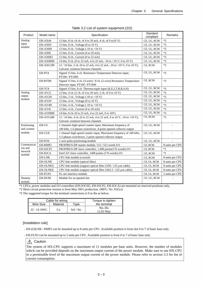
Table 3.2 List of system equipment (2/2)
Product Model name Specification Standard compliant
Remarks
Analog
input
module
EH-AX44 12 bits, 8 ch. (4 ch. of 4 to 20 mA, 4 ch. of 0 to10 V) CE, UL, RCM *3
EH-AX8V 12 bits, 8 ch., Voltage (0 to 10 V) CE, UL, RCM *3
EH-AX8H 12 bits, 8 ch., Voltage (-10 to +10 V) CE, UL, RCM *3
EH-AX8I 12 bits, 8 ch., Current (4 to 20 mA) CE, UL, RCM *3
EH-AX8IO 12 bits, 8 ch., Current (0 to 22 mA) CE, UL, RCM *3
EH-AXH8M 14 bits, 8 ch. (0 to 22 mA, 4 to 22 mA, -10 to +10 V, 0 to 10 V) CE, UL, RCM *3
EH-AXG5M 12 / 16 bits, 5 ch. (0 to 22 mA, 4 to 22 mA, -10 to +10 V, 0 to 10 V),
Galvanic isolation between channels
CE, RCM *3
EH-PT4 Signed 15 bits, 4 ch. Resistance Temperature Detector input,
PT100 / PT1000
CE, UL, RCM *3
EH-RTD8 Signed 15 bits, 6 ch. (3-wire) / 8 ch. (2-wire) Resistance Temperature
Detector input, PT100 / PT1000
CE, RCM *3
EH-TC8 Signed 15 bits, 8 ch. Thermocouple input (K,E,J,T,B,R,S,N) CE, UL, RCM *3
Analog
output
module
EH-AY22 12 bits, 4 ch. (2 ch. of 4 to 20 mA, 2 ch. of 0 to 10 V) CE, UL, RCM *3
EH-AY2H 12 bits, 2 ch., Voltage (-10 to +10 V) CE, UL, RCM *3
EH-AY4V 12 bits, 4 ch., Voltage (0 to 10 V) CE, UL, RCM *3
EH-AY4H 12 bits, 4 ch., Voltage (-10 to +10 V) CE, UL, RCM *3
EH-AY4I 12 bits, 4 ch., Current (4 to 20 mA) CE, UL, RCM *3
EH-AYH8M 14 bits, 8 ch. (0 to 22 mA, 4 to 22 mA, 0 to 10V) CE, UL, RCM *3
EH-AYG4M 12 / 16 bits, 4 ch. (0 to 22 mA, 4 to 22 mA, 0 to 10 V, -10 to +10 V),
Galvanic isolation between channels
CE, RCM *3
Positioning
and counter
module
EH-CU 2 channels high-speed counter input, Maximum frequency of
100 kHz, 1/2-phases switchover, 4-point opened collector output
CE, UL, RCM -
EH-CUE
1 channel high-speed counter input, Maximum frequency of 100 kHz,
1/2-phases switchover, 2-point opened collector output
CE, UL, RCM -
EH-POS 1-axis pulse positioning module CE, UL, RCM -
Communicat
ion and
network
module
EH-RMP2 PROFIBUS-DP master module, 512 / 512 words I/O CE, RCM 8 units per CPU
EH-IOCP2 PROFIBUS-DP slave controller, 1,408 points(176 words) I/O CE, RCM *1
EH-IOCA EterCAT slave controller, 1408 points (176 words) I/O CE, RCM *1
EH-LNK CPU link module (coaxial) CE, RCM 8 units per CPU
EH-OLNK CPU link module (optical fiber) CE, UL, RCM 8 units per CPU
EH-OLNKG CPU link module (support optical fiber GI50 / 125 m cable) CE, UL, RCM 8 units per CPU
EH-OLNKE CPU link module (support optical fiber GI62.5 / 125 m cable) CE, UL, RCM 8 units per CPU
EH-FLN3 FL-net interface module CE, UL, RCM 2 units per CPU
Dummy
module EH-DUM Module for an opened slot CE, UL, RCM -
*1 CPUs, power modules and I/O controllers (EH-IOCH2, EH-IOCP2, EH-IOCA) are mounted on reserved positions only.
*2 Short circuit protection version is from May 2001 production. (MFG. No. 01Exx)
*3 The suggested torque for the terminal connections is 9 in-lbs as below.
Cable for wiring Torque to tighten the terminal Wire Size Material Type
22 - 14 AWG Cu Sol / Str. 9in.-lbs
(1.02 Nm)
[Installation rule]
- EH-(O)LNK / RMP2 can be mounted up to 8 units per CPU. Available position is from slot 0 to 7 of basic base only.
- EH-FLN3 can be mounted up to 2 units per CPU. Available position is from 0 to 7 of basic base only.
! Caution
The system of HX-CPU supports a maximum of 11 modules per base units. However, the number of modules
which can be provided depends on the maximum output current of the power module. Make sure to use HX-CPU
in a permissible level of the maximum output current of the power module. Please refer to section 3.3 for list of
current consumption.

Chapter 3 General Specifications
3 – 4
(2) Peripheral devices
Table 3.3 Peripheral device of HX series
Product Model name Specification Remarks
HX-CODESYS HX-CDS IEC 61131-3 compliant programming software with ST (Structured Text), SFC
(Sequential Function Chart), FBD (Function Block Diagram ),
LD (Ladder Logic Diagram) and IL (Instruction List).
Supported operating system:
Windows XP, Windows 7 (32 / 64 bit), Windows 8, Windows 8.1,
Windows 10
Multilingual support (Japanese, English, German, Spanish, French, Italy, Russian,
Chinese)
-
* Please refer to "Software manual of HX series" for the PC operating environment necessary to use it.
Chapter 3 General Specifications
3 – 5
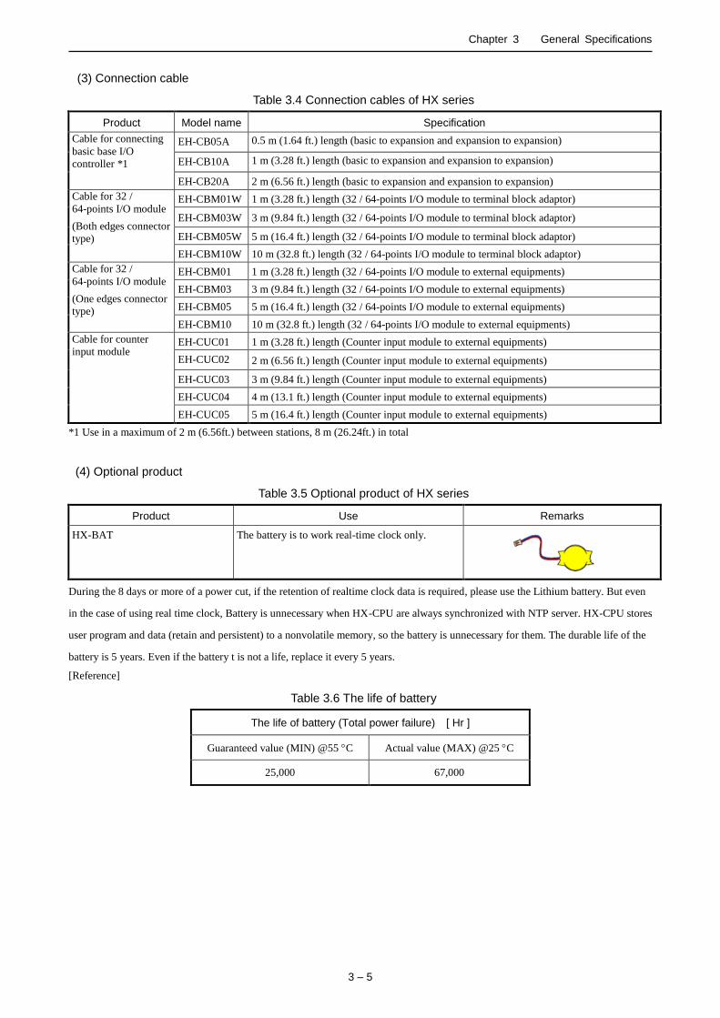
(3) Connection cable
Table 3.4 Connection cables of HX series
Product Model name Specification
Cable for connecting
basic base I/O
controller *1
EH-CB05A 0.5 m (1.64 ft.) length (basic to expansion and expansion to expansion)
EH-CB10A 1 m (3.28 ft.) length (basic to expansion and expansion to expansion)
EH-CB20A 2 m (6.56 ft.) length (basic to expansion and expansion to expansion)
Cable for 32 /
64-points I/O module
(Both edges connector
type)
EH-CBM01W 1 m (3.28 ft.) length (32 / 64-points I/O module to terminal block adaptor)
EH-CBM03W 3 m (9.84 ft.) length (32 / 64-points I/O module to terminal block adaptor)
EH-CBM05W 5 m (16.4 ft.) length (32 / 64-points I/O module to terminal block adaptor)
EH-CBM10W 10 m (32.8 ft.) length (32 / 64-points I/O module to terminal block adaptor)
Cable for 32 /
64-points I/O module
(One edges connector
type)
EH-CBM01 1 m (3.28 ft.) length (32 / 64-points I/O module to external equipments)
EH-CBM03 3 m (9.84 ft.) length (32 / 64-points I/O module to external equipments)
EH-CBM05 5 m (16.4 ft.) length (32 / 64-points I/O module to external equipments)
EH-CBM10 10 m (32.8 ft.) length (32 / 64-points I/O module to external equipments)
Cable for counter
input module EH-CUC01 1 m (3.28 ft.) length (Counter input module to external equipments)
EH-CUC02 2 m (6.56 ft.) length (Counter input module to external equipments)
EH-CUC03 3 m (9.84 ft.) length (Counter input module to external equipments)
EH-CUC04 4 m (13.1 ft.) length (Counter input module to external equipments)
EH-CUC05 5 m (16.4 ft.) length (Counter input module to external equipments)
*1 Use in a maximum of 2 m (6.56ft.) between stations, 8 m (26.24ft.) in total
(4) Optional product
Table 3.5 Optional product of HX series
Product Use Remarks
HX-BAT The battery is to work real-time clock only.
During the 8 days or more of a power cut, if the retention of realtime clock data is required, please use the Lithium battery. But even
in the case of using real time clock, Battery is unnecessary when HX-CPU are always synchronized with NTP server. HX-CPU stores
user program and data (retain and persistent) to a nonvolatile memory, so the battery is unnecessary for them. The durable life of the
battery is 5 years. Even if the battery t is not a life, replace it every 5 years.
[Reference]
Table 3.6 The life of battery
The life of battery (Total power failure) [ Hr ]
Guaranteed value (MIN) @55 C Actual value (MAX) @25 C
25,000 67,000
Chapter 3 General Specifications
3 – 6
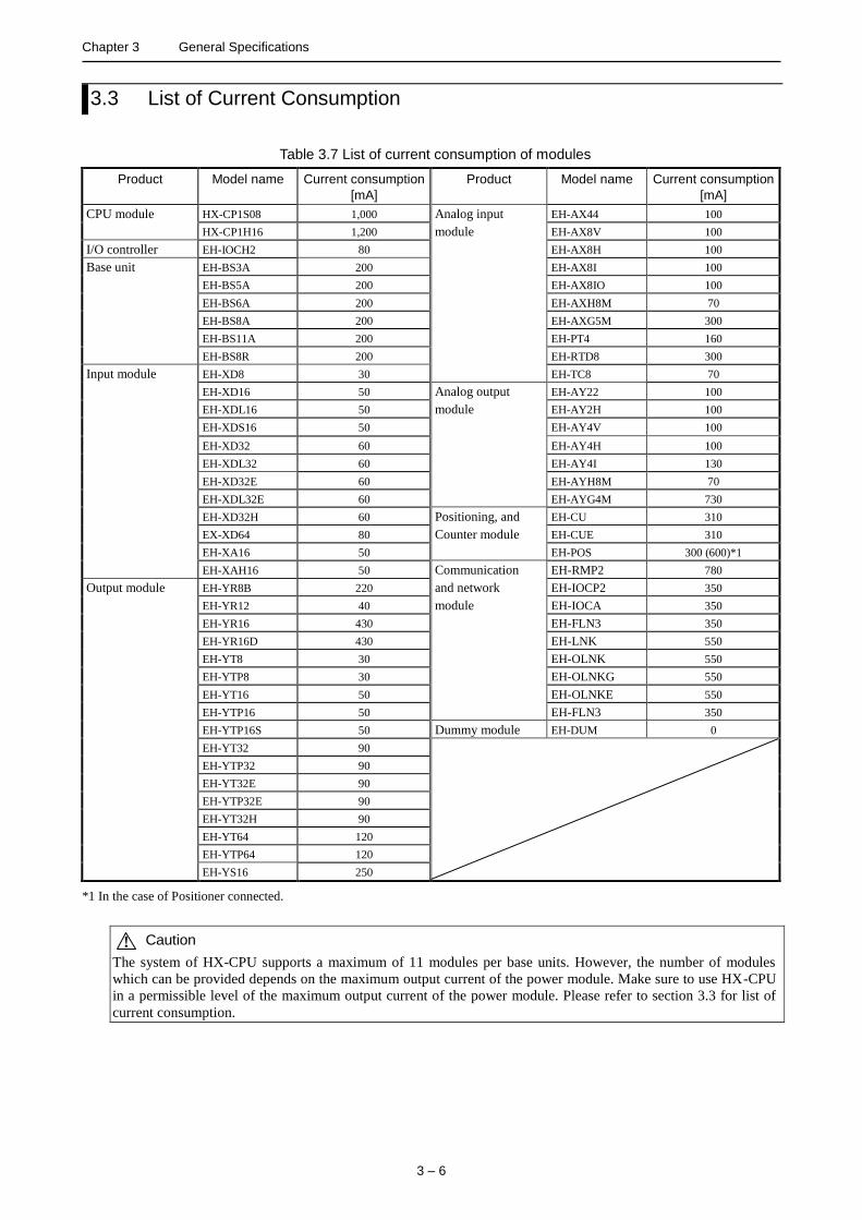
3.3 List of Current Consumption
Table 3.7 List of current consumption of modules
Product Model name Current consumption
[mA]
Product Model name Current consumption
[mA]
CPU module HX-CP1S08 1,000 Analog input EH-AX44 100
HX-CP1H16 1,200 module EH-AX8V 100
I/O controller EH-IOCH2 80 EH-AX8H 100
Base unit EH-BS3A 200 EH-AX8I 100
EH-BS5A 200 EH-AX8IO 100
EH-BS6A 200 EH-AXH8M 70
EH-BS8A 200 EH-AXG5M 300
EH-BS11A 200 EH-PT4 160
EH-BS8R 200 EH-RTD8 300
Input module EH-XD8 30 EH-TC8 70
EH-XD16 50 Analog output EH-AY22 100
EH-XDL16 50 module EH-AY2H 100
EH-XDS16 50 EH-AY4V 100
EH-XD32 60 EH-AY4H 100
EH-XDL32 60 EH-AY4I 130
EH-XD32E 60 EH-AYH8M 70
EH-XDL32E 60 EH-AYG4M 730
EH-XD32H 60 Positioning, and EH-CU 310
EX-XD64 80 Counter module EH-CUE 310
EH-XA16 50 EH-POS 300 (600)*1
EH-XAH16 50 Communication EH-RMP2 780
Output module EH-YR8B 220 and network EH-IOCP2 350
EH-YR12 40 module EH-IOCA 350
EH-YR16 430 EH-FLN3 350
EH-YR16D 430 EH-LNK 550
EH-YT8 30 EH-OLNK 550
EH-YTP8 30 EH-OLNKG 550
EH-YT16 50 EH-OLNKE 550
EH-YTP16 50 EH-FLN3 350
EH-YTP16S 50 Dummy module EH-DUM 0
EH-YT32 90
EH-YTP32 90
EH-YT32E 90
EH-YTP32E 90
EH-YT32H 90
EH-YT64 120
EH-YTP64 120
EH-YS16 250
*1 In the case of Positioner connected.
! Caution
The system of HX-CPU supports a maximum of 11 modules per base units. However, the number of modules
which can be provided depends on the maximum output current of the power module. Make sure to use HX-CPU
in a permissible level of the maximum output current of the power module. Please refer to section 3.3 for list of
current consumption.
4 – 1
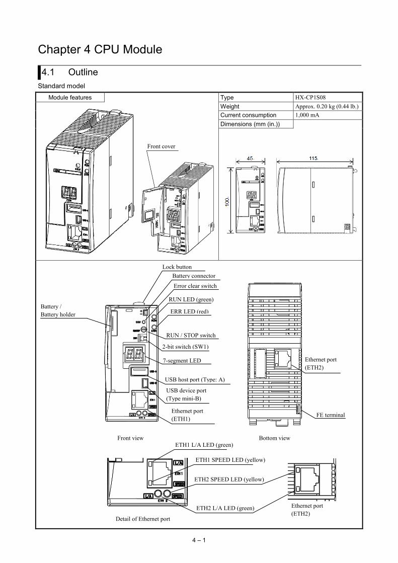
Chapter 4 CPU Module
4.1 Outline Standard model
Module features Type HX-CP1S08
Front cover
Weight Approx. 0.20 kg (0.44 lb.) Current consumption 1,000 mA Dimensions (mm (in.))
Front view Bottom view
RUN LED (green)
ERR LED (red) Battery / Battery holder
Error clear switch
RUN / STOP switch
USB host port (Type: A)
USB device port (Type mini-B)
Ethernet port (ETH1)
Ethernet port (ETH2)
FE terminal
Battery connector
2-bit switch (SW1)
7-segment LED
Lock button
Detail of Ethernet port
ETH1 L/A LED (green)
ETH1 SPEED LED (yellow)
ETH2 L/A LED (green)
ETH2 SPEED LED (yellow)
Ethernet port (ETH2)

Chapter 4 CPU Module
4 – 2
Full function model
Module features Type HX-CP1H16
Front cover
Weight Approx. 0.24 kg (0.53 lb.) Current consumption 1,200 mA Dimensions (mm (in.))
Ethernet port (ETH2)
Front view Bottom view
RUN LED (green)
ERR LED (red)
READY LED (green)
ACCESS LED (yellow)
Battery / Battery holder
Error clear switch
RUN/STOP switch
USB host port (Type: A)
USB device port (Type: mini-B)
Ethernet port (ETH1)
Ethernet port (ETH3)
Ethernet port (ETH2)
Serial port
FE terminal
SD card switch (SW2)
Battery connector
SD card slot
4-bit switch (SW3)
2-bit switch (SW1)
7-segment LED
Lock button
Detail of Ethernet port
ETH3 L/A LED (green)
ETH3 SPEED LED (yellow)
ETH1 L/A LED (green)
ETH1 SPEED LED (yellow)
ETH2 L/A LED (green)
ETH2 SPEED LED (yellow)

Chapter 4 CPU Module
4 – 3
Table 4.1 Each description of items in CPU module
No. Item Description 1 RUN LED Indicates operation status. (Green lighting: RUN / off: STOP) 2 ERR LED Indicates error status. (Red blinking: battery error, I/O module mismatch or initialization
of RTC (real time clock) etc. / red lighting: other errors / off: no error) 3 7-segment LED Indicates error code.
And indicates the status of the USB memory with dot LED “.” on the right. (Lighting: mounting, off: unmount)
4 USB host port (Type:A)
USB host function (Data logging) is supported. User program is needed to use data logging (File read / write / compare). Support device is USB memory only.
5 USB device port (Type:mini-B)
USB port supports gateway function (with HX-CODESYS) only. USB cable is not included with CPU package nor supplied by Hitachi-IES. Use type Mini-B USB cable.
6 Serial port (Full function model)
Serial communication port has a RS-485 interface with terminal. It is supporting Modbus-RTU (master / slave) and general purpose. User program is needed to use general purpose.
7 Ethernet port (ETH 1,2)
Ethernet port 1, 2 have both gateway function (with HX-CODESYS / HMI / OPC) and IEC programming function supporting global network variable, EtherCAT master, Modbus-TCP client / server and OPC-UA server. Do not use other function if EtherCAT master can be used.
8 Ethernet port (ETH 3) (Full function model)
Ethernet port 3 has both gateway function (with HX-CODESYS / HMI / OPC) and IEC programming function supporting global network variable, Modbus-TCP client / server and OPC-UA server. EtherCAT master function is not supported.
9 SD card slot (Full function model)
SD / SDHC card are supported. Data logging function is supported. User program is needed to use data logging (File read / write / compare).
10 RUN / STOP switch When this switch position is in RUN (left), CPU start executing program. At the same time, remote controlling is enabled, in which case, CPU is started or stopped by HX-CODESYS over communication. When this switch position is in STOP (right), CPU stop executing program. In this status, remote controlling is disabled.
11 Error clear switch (E.CLR)
If any error occurs, error code is displayed in 7-segment LED and remains after the error cause is deactivated. When pressing this button, error code is cleared. If the error cause is still remaining, error code will be displayed again.
12 SD card switch(SW2) (Full function model)
When pressing this switch, SD card is unmounted. Please check lights-out of READY LED before pull out SD card.
13 ACCESS LED (Full function model)
Not supported.
14 READY LED (Full function model)
Indicates the status of SD card. Do not pull out SD card during lighting. (Green lighting: mounting, off: unmount)
15 SPEED LED Indicates communication speed of each Ethernet port. (Yellow lighting: 100Mbps, off: 10Mbps or link-down)
16 L/A LED Indicates the status of each Ethernet communication. (Green lighting: Ethernet link-up, blinking: Data is sent or received, off: link-down)
17 2-bit switch (SW1) User program can be downloaded, uploaded or verified according to switch position.* Resetting the factory default settings. Please refer to section 13.2.
18 4-bit switch (SW3) (Full function model)
Not supported. Please keep off.
19 Lock button Press this button to dismount from the base units. Module can be fixed firmly by a screw of M4×10mm (0.39 in.).
20 Front cover Open this cover when operating the switch, button or replacing the battery. Keep the cover closed while cpu execute program.
21 Battery holder Battery connector
RTC (real time clock) data is retained by battery. Data specified as RETAIN and PERSISTENT and user program are retained without battery. -The battery has polarity. When plugging in, check the polarity carefully. -The battery is not included with CPU package. -Replace the battery every five years even when doesn’t reach the end of the battery.
22 FE terminal Connect to Class D grounding. * User program download function will be supported in near future.
USB memory STATUS
Reserved

Chapter 4 CPU Module
4 – 4
! Caution Note the cautions for the communication ports. Since EtherCAT supports 100 Mbps only, communication error might occur depending on installation environment, cable length or external noise. In this case, check your installation environments and take appropriate countermeasures to reduce noise.

Chapter 4 CPU Module
4 – 5
4.2 Performance Specifications
Table 4.2 Performance specifications
Item Specification
HX-CP1S08 HX-CP1H16 Model Standard Model Full Function Model User program memory *1 8 MB 16 MB Source file memory *1 8 MB 16 MB *2 Data memory (non-retain) *1 8 MB 16 MB Data memory (retain) *1 250 kB Data memory (persistent) *1 250 kB Field bus / Marker memory 48 kB Number of expansion base units 5 units Expansion cables Between stations : 0.5 m, 1 m, 2 m, Total length: 8 m or less Number of I/O points (using 64 points module) 4,224 points I/O modules Common with EH-150 / EHV series (Refer to section 3.2 for detail) Programming language IEC61131-3 compliant 5 languages + CFC
LD : Ladder Logic Diagram FBD : Function Block Diagram SFC : Sequential Function Chart IL : Instruction List ST : Structured Text CFC : Continuous Function Chart
I/O update cycle Refresh processing Execution speed Boolean instruction min. 1.0 ns
Double-precision floating point min. 6.6 ns Communication interfaces
Protocol CODESYS V3 protocol USB device 1port (Mini-B type connector, USB 2.0 High speed) USB host 1 port (A type connector, USB 2.0 High speed) for USB memory *3 Ethernet 2 ports (10BASE-T / 100BASE-TX) 3 ports (10BASE-T / 100BASE-TX) Serial - 1 port (RS-485)
Available communication
OPC UA Web Visualization - NTP (network time protocol) FTP (server) EtherCAT Master*6 (Communication cycle) min. 1ms Modbus-TCP Client Modbus-TCP Server (Maximum number of clients : 16) Modbus-RTU Client - Modbus-RTU Server -
SD memory card slot - 1 slot (SD / SDHC) Display and switch
Display RUN LED, ERR LED, 7-segmented LED (2digits) RUN / STOP switch STOP / RUN (Remote control of RUN / STOP over communication from
HX-CODESYS is enable when switch position is in RUN.) Error clear switch Clear of error code 2-bit switch (SW1) Reserved for future 4-bit switch (SW3) - Reserved for future
Real-time clock Built-in RTC (deviation ±60 s/month at 25 °C) Battery (Option for RTC) HX-BAT (for RTC) *4 Startup time About 20 to 30 s *5 Maintenance function
Self-diagram microcomputer error, watchdog timer error, memory error, program error, system ROM / RAM error, scan time error, battery under-voltage detection,
and others Compliant CE, RCM Version of CODESYS runtime 3.5.8.21 or later 3.5.8.22 or later Available version of CODESYS 3.5 SP8 patch4 or later *1 Because the additional information of the program is stored, it becomes slightly smaller than a specification level. *2 The source file memory is shared with files for Web visualization. *3 For data storage. *4 The battery is option for RTC. *5 It depends on the size of the user program. *6 EtherCAT master function must be configured it alone. Do not configure the other function with EtherCAT master function.

Chapter 4 CPU Module
4 – 6
Table 4.3 EtherCAT functional specifications
Item Specification Protocol EtherCAT® protocol (CoE) Supported communication profiles CoE (PDO , SDO) Synchronization (DC) Supported Physical layer 100BASE-TX Modulation system Baseband communication Transmission speed 100 Mbps (100BASE-TX) Duplex mode Full duplex / Auto MDI Topology Daisy-chain, tree Transmission medium Twisted pair cable more over category 5 with shield Transmission range 100 m or less between nodes (IEEE802.3) Maximum number of slaves 255 Maximum process data size Input 5,736 bytes / Output 5,736 bytes Maximum data size of slave Input 1,434 bytes / Output 1,434 bytes Maximum massage size 2,048 bytes Communication cycle time 1 ms or more Process data communication ・PDO Mapping with the CoE protocol
・Redundant communication even in a slave malfunction ・Stop operation in a slave malfunction
SDO communication CoE ・Emergency message server (receive from slave) ・SDO request / Response
Configuration ・Setting node address by network scan from programming tool (HX-CODESYS) ・Display of network information
RAS function ・Slave configuration check in the network starting ・Read-out of the error information ・Trouble shoot information
Slave information ・Slave valid / invalid ・joining / out-network of a slave (Slave option)
Mail box ・CoE (CAN open / CAN application layer over EtherCAT)

Chapter 4 CPU Module
4 – 7
Table 4.4 Programming functional specifications
Item Specification
Task Specifi- cations
Number of periodic task 32 periodic task priority 0 to 31 Number of event task 8 System event 25 kinds such as Run / Stop Number of status task 8 Number of freewheeling task 1
Kinds of POU Program, Function block, Function Data Types Bool BOOL, BYTE, WORD, DWORD, LWORD
Integer SINT, INT, DINT, LINT Unsigned integer USINT, UINT, UDINT, ULINT Real REAL, LREAL String STRING, WSTRING Time TIME (T), LTIME (LT) Date / time of day TIME_OF_DAY (TOD), DATE_AND_TIME (DT), DATE (D) Others STRUCT, UNION, ARRAY, ENUMERATION, SUBRANGE, REFERENCE,
POINTER, ANY, BIT Array number of dimensions 3
Instructions Arithmetic instructions ADD, MUL, SUB, DIV, MOD, MOVE Boolean instructions AND, OR, XOR, NOT Bit shift SHL, SHR, ROL, ROR Selection SEL, MAX, MIN, LIMIT, MUX Comparison GT, LT, LE, GE, EQ, NE Call CAL Type conversion BOOL_TO_INT, WORD_TO_INT, and so on Arithmetic Functions ABS, SQRT, LN, LOG, EXP, SIN, COS, TAN, ASIN, ACOS, ATAN, EXPT IEC extension DELETE, ISVALIDREF, NEW, QUERYINTERFACE, QUERYPOINTER,
AND_THEN, OR_ELSE, TRY, CATCH, FINALLY, ENDTRY, INDEXOF, ADR, BITADR, INDEXOF, SIZEOF, ANDN, ORN, XORN
Standard library
Flip-Flop RS, SR Counter CTD, CTU, CTUD STRING Functions CONCAT, DELETE, FIND, INSERT, LEFT, LEN, MID, REPLACE, RIGHT Timer TOF, TON, TP Edge Detection F_TRIG, R_TRIG Others RTC
Other library (extract)
UTIL BCD Conversions BCD_TO_INT, INT_TO_BCD Bit / Byte Functions EXTRACT, PACK, PUTBIT, UNPACK Mathematic Auxiliary Functions
DEREVATIVE, INTEGRAM LIN_TRAFO, STATISTICS_INT, STATISTICS_REAL,VARIANCE
PID PD, PID, PID_FIXCYCLE Signal Generators BLINK, FREQ_MEASURE, GEN Function Manipulators
CHARCURVE, RAMP_INT, RAMP_REAL
Analog Value Processing
HYSTERESIS, LIMITALARM
FILE Directory DirClose, DirCreate, DirList, DirOpen, DirRemove, DirRename File Close, Copy, Delet, EOF, Flush, GetAttribute, GetPos, GetSize,
GetTime, Open, Read, Rename, SetPos, Write DTU GetDateAndTime, SetDateAndTime
Chapter 4 CPU Module
4 – 8
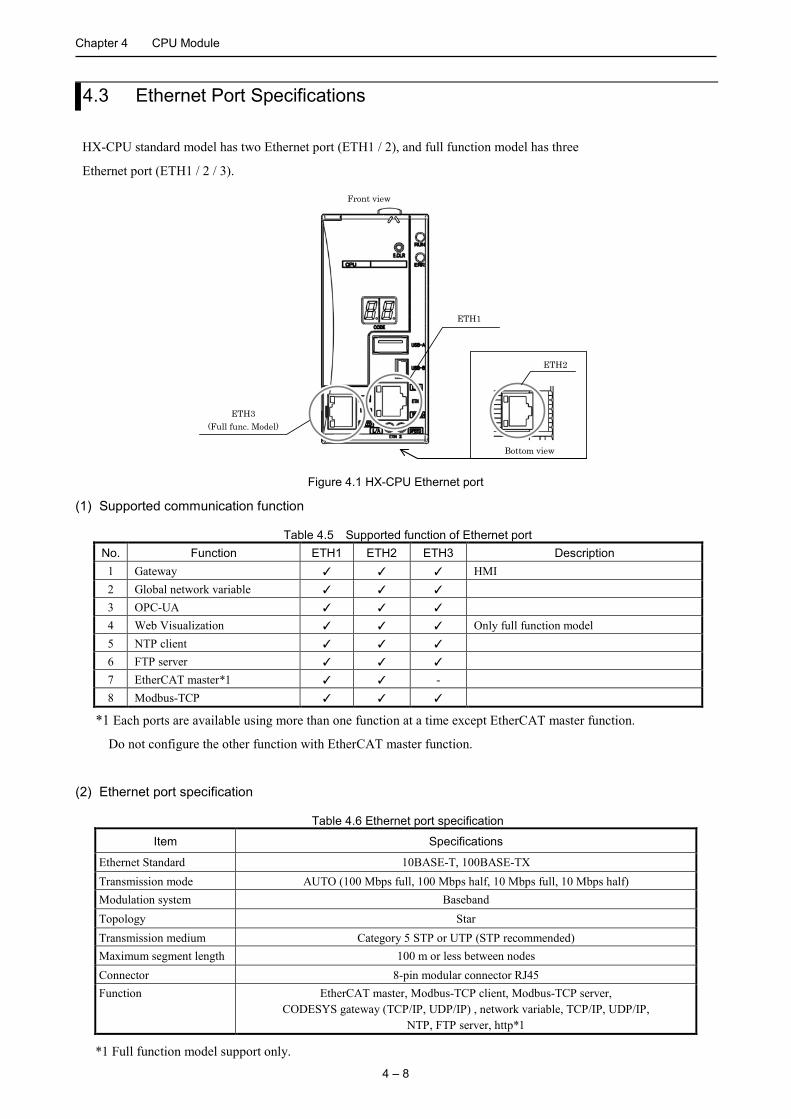
4.3 Ethernet Port Specifications
HX-CPU standard model has two Ethernet port (ETH1 / 2), and full function model has three
Ethernet port (ETH1 / 2 / 3).
ETH3 (Full func. Model)
ETH1
ETH2
Bottom view
Front view
Figure 4.1 HX-CPU Ethernet port
(1) Supported communication function
Table 4.5 Supported function of Ethernet port No. Function ETH1 ETH2 ETH3 Description
1 Gateway HMI 2 Global network variable 3 OPC-UA 4 Web Visualization Only full function model 5 NTP client 6 FTP server 7 EtherCAT master*1 - 8 Modbus-TCP
*1 Each ports are available using more than one function at a time except EtherCAT master function.
Do not configure the other function with EtherCAT master function.
(2) Ethernet port specification
Table 4.6 Ethernet port specification
Item Specifications
Ethernet Standard 10BASE-T, 100BASE-TX Transmission mode AUTO (100 Mbps full, 100 Mbps half, 10 Mbps full, 10 Mbps half) Modulation system Baseband Topology Star Transmission medium Category 5 STP or UTP (STP recommended) Maximum segment length 100 m or less between nodes Connector 8-pin modular connector RJ45 Function EtherCAT master, Modbus-TCP client, Modbus-TCP server,
CODESYS gateway (TCP/IP, UDP/IP) , network variable, TCP/IP, UDP/IP, NTP, FTP server, http*1
*1 Full function model support only.
Chapter 4 CPU Module
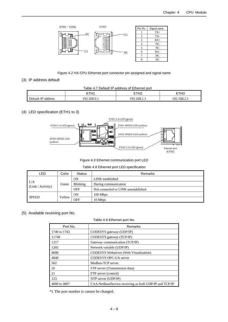
4 – 9
Pin No. Signal name
1 TX+
2 TX-
3 RX+
4 NC
5 NC
6 RX-
7 NC
8 NC
ETH1・ETH2
[8]
[1]
ETH3
[1]
[8]
Figure 4.2 HX-CPU Ethernet port connector pin assigned and signal name
(3) IP address default
Table 4.7 Default IP address of Ethernet port
ETH1 ETH2 ETH3
Default IP address 192.168.0.1 192.168.1.1 192.168.2.1
(4) LED specification (ETH1 to 3)
ETH1 L/A LED (green)
ETH1 SPEED LED (yellow)
ETH2 SPEED LED (yellow)
ETH2 L/A LED (green)
ETH3 L/A LED (green)
ETH3 SPEED LED
(yellow)
Ethernet port
(ETH2)
Figure 4.3 Ethernet communication port LED
Table 4.8 Ethernet port LED specification
LED Color Status Remarks
L/A
(Link / Activity) Green
ON LINK established
Blinking During communication
OFF Not connected or LINK unestablished
SPEED Yellow ON 100 Mbps
OFF 10 Mbps
(5) Available receiving port No.
Table 4.9 Ethernet port No.
Port No. Remarks
1740 to 1743 CODESYS gateway (UDP/IP)
11740 CODESYS gateway (TCP/IP)
1217 Gateway communication (TCP/IP)
1202 Network variable (UDP/IP)
8080 CODESYS Webserver (Web Visualization)
4840 CODESYS OPC-UA server
502 Modbus-TCP server
20 FTP server (Transmission data)
21 FTP server (control)
123 NTP server (UDP/IP)
4000 to 4007 CAA.NetBaseService receiving as both UDP/IP and TCP/IP
*1 The port number is cannot be changed.

Chapter 4 CPU Module
4 – 10
4.4 USB Port Specifications
USB-A (Host)
Front view
USB-B (Device)
Figure 4.4 USB port
(1) USB-A(Host)
USB-A port is a USB host port that can connect a USB memory. (Connector:Type-A)
It supports the data storage function. To operate the file, creating a user program is required. Enabled devices is the
only USB memory. When USB memory is used, please check an environmental condition of the USB memory and
use in the rated range of use. The specifications of the USB memory may be changed by a maker and may not work
normally. Please use under customer's responsibility.
(2) USB-B(Device)
USB-B port supports a gateway (Connection with a HX-CODESYS) function. (Connector:Type-miniB) Use a
commercial USB cable with ferrite core.
Table 4.10 USB port specification
Items Specification
USB-A (Host)
Standard USB 2.0 High Speed (480 Mbps) Connector A type File system FAT16 / 32, ext2 Maximum Volume 32 GB 1 file maximum volume
2 GB
Bus power 500 mA Distance 5 m Function Access USB memory (Data logging, file operation, etc.)
USB-B (Device)
Standard USB 2.0 High Speed (480 Mbps) Connector mini-B type Distance 5 m Function CODESYS gateway

Chapter 4 CPU Module
4 – 11
4.5 SD Card Specifications
SDcard slot
Figure 4.5 SD card
HX-CPU(Full function model) is supporting a SD card. To operate the file, creating a user program is required. When
SD card is used, please check an environmental condition of the SD card and use in the rated range of use. The
specifications of the SD card memory may be changed by a maker and may not work normally. Please use under
customer's responsibility.
Table 4.11 SD card specification
Items Specification
SD card
Standard SD (up to 2 GB) , SDHC (2 to 32 GB) Bus interface Normal speed, High speed Bus speed Maximum 25 MB/s Version 2.00 File system FAT16 / 32, ext2 Maximum volume 32 GB 1 file maximum size 2 GB Function Access SD card (Data logging, File operation, etc.)
Chapter 4 CPU Module
4 – 12
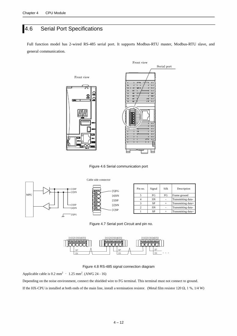
4.6 Serial Port Specifications
Full function model has 2-wired RS-485 serial port. It supports Modbus-RTU master, Modbus-RTU slave, and
general communication.
Front view
Front view
Serial port
Figure 4.6 Serial communication port
MPU
[5]FG
[1]SP
[2]SN
[4]SN [3]SP
Pin no. Signal Silk Description
5 FG FG Frame ground
4 SN - Transmitting data-
3 SP + Transmitting data+
2 SN - Transmitting data-
1 SP + Transmitting data+
[5]FG
[4]SN
[3]SP
[2]SN
[1]SP
Cable side connector
Figure 4.7 Serial port Circuit and pin no.
・・・ SP SN
SP SN
SP SN
[1] [2] [3] [4] [5] [1] [2] [3] [4] [5] [1] [2] [3] [4] [5]
Figure 4.8 RS-485 signal connection diagram
Applicable cable is 0.2 mm2 – 1.25 mm2. (AWG 24 - 16)
Depending on the noise environment, connect the shielded wire to FG terminal. This terminal must not connect to ground.
If the HX-CPU is installed at both ends of the main line, install a termination resistor. (Metal film resistor 120 Ω, 1 %, 1/4 W)

Chapter 4 CPU Module
4 – 13
4.7 Battery Specifications
The battery is not attached. (Option) In the case of the following, use the battery.
- During the 8 days or more of an interruption of the power supply, if the retention of realtime clock data
is required
- When HX-CPU is used by more than 50 of environment.
In the case of the following, the battery is not required. User memory and retain memory are retained by
nonvolatile memory.
- When the time is synchronous with a NTP server.
Type : HX-BAT
Figure 4.9 HX-CPU battery (option)
How to install a battery to HX-CPU in the following steps. Be careful about the polarity of a battery.
How to install the battery
1] Prepare a new battery.(HX-BAT)
2] Replace the battery while the power supply for the basic base is turned on.
3] Remove the consumed lithium battery from the battery case, and remove the connector on the battery side.
4] Insert the connector on the battery side to the CPU module connector.
Insert the red lead wire to + and the black lead wire to -.
5] Fold the excess lead wire and store it in the space for lead wire storage.
(Otherwise, the wire may be severed by the front cover.)
If replacing the battery without power supplied, power off time should be less than 30 minute.
Battery connector
Front view
Front cover
Battery connector
Battery
Battery holder
[+] lead (Red)
[ - ] lead( Black)
Figure 4.10 Install battery
Chapter 4 CPU Module
4 – 14
Refer to the following tables in the lifetime of the battery. Table 4.12 Battery life
Battery life (Total time interruption of power supply ) [ Hr ]
Guaranteed value (MIN) @55 °C Actual value (MAX) @25 °C
25,000 67,000
- When using the battery, enable the battery error detection. Refer to the manual section 2.6 Configuration of HX
series application manual (Software).
- The life time of the battery means the total time of interruption of power supply for PAC.
- When ERR LED is displayed flashing or the 7-segment LED is displayed 71, replace the battery within 7 days.
- The durable life of the battery is 5 years. Even if the battery is not a life, replace it every 5 years.
DANGER
Precaution when handling the battery. Use HX-BAT for the new battery. Be careful because a false replacement may cause the battery to explode. Do not connect + and - of the battery reversely, do not charge disassemble, heat them, throw them into the fire, short circuit them.
CAUTION
Disposal (collection) of the battery Old battery should be individually put in plastic bag of similar (to prevent short circuit) and a disposal company should be requested to dispose of them.
!
!
5 – 1
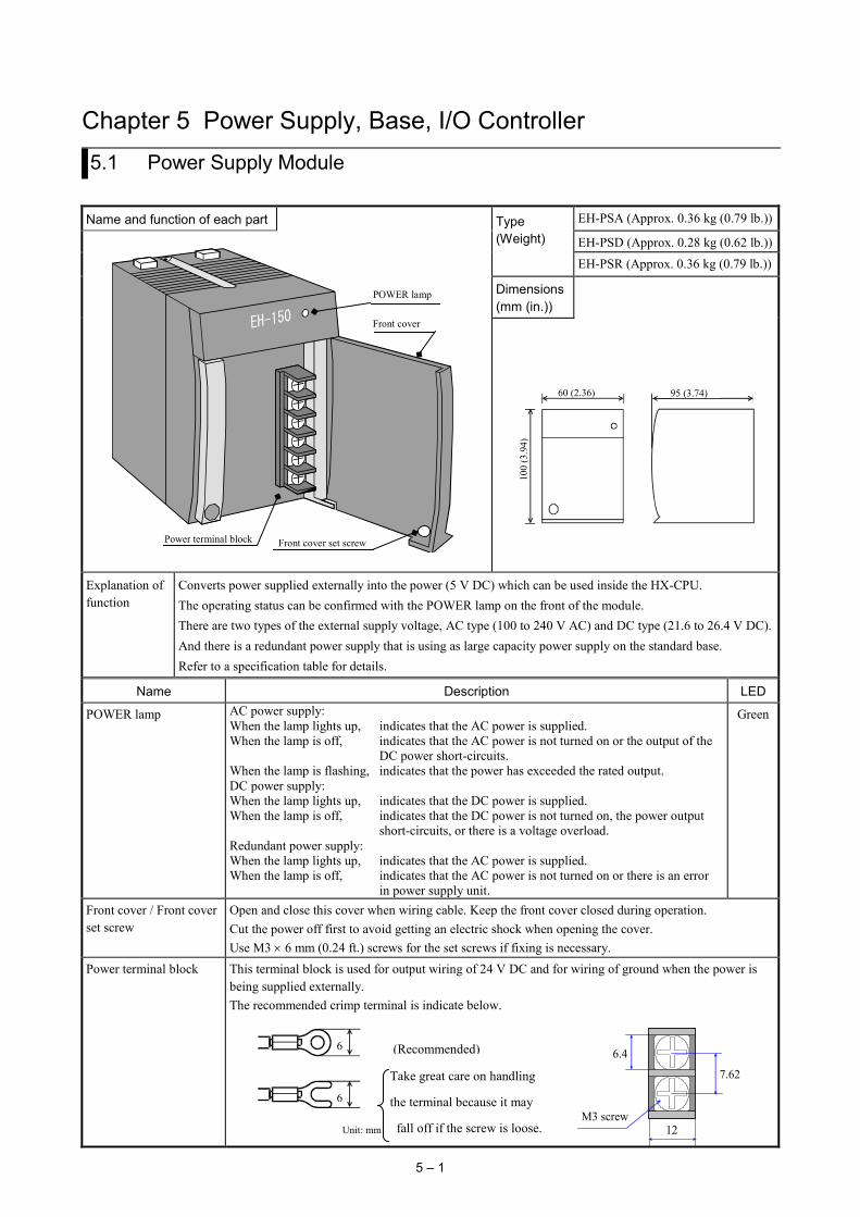
Chapter 5 Power Supply, Base, I/O Controller 5.1 Power Supply Module
Name and function of each part Type (Weight)
EH-PSA (Approx. 0.36 kg (0.79 lb.))
EH-PSD (Approx. 0.28 kg (0.62 lb.))
EH-PSR (Approx. 0.36 kg (0.79 lb.))
Dimensions (mm (in.))
60 (2.36)
100
(3.9
4)
95 (3.74)
Explanation of function
Converts power supplied externally into the power (5 V DC) which can be used inside the HX-CPU. The operating status can be confirmed with the POWER lamp on the front of the module. There are two types of the external supply voltage, AC type (100 to 240 V AC) and DC type (21.6 to 26.4 V DC). And there is a redundant power supply that is using as large capacity power supply on the standard base. Refer to a specification table for details.
Name Description LED
POWER lamp AC power supply: When the lamp lights up, indicates that the AC power is supplied. When the lamp is off, indicates that the AC power is not turned on or the output of the DC power short-circuits. When the lamp is flashing, indicates that the power has exceeded the rated output. DC power supply: When the lamp lights up, indicates that the DC power is supplied. When the lamp is off, indicates that the DC power is not turned on, the power output short-circuits, or there is a voltage overload. Redundant power supply: When the lamp lights up, indicates that the AC power is supplied. When the lamp is off, indicates that the AC power is not turned on or there is an error in power supply unit.
Green
Front cover / Front cover set screw
Open and close this cover when wiring cable. Keep the front cover closed during operation. Cut the power off first to avoid getting an electric shock when opening the cover. Use M3 × 6 mm (0.24 ft.) screws for the set screws if fixing is necessary.
Power terminal block This terminal block is used for output wiring of 24 V DC and for wiring of ground when the power is being supplied externally. The recommended crimp terminal is indicate below.
POWER lamp
Front cover
Power terminal block Front cover set screw
6
6
Unit: mm
(Recommended)
Take great care on handling
the terminal because it may
fall off if the screw is loose.
7.62
6.4
12 M3 screw

Chapter 5 Power Supply, Base, I/O Controller,
5 – 2
(1) EH-PSA
Item Specification
Rated output voltage 5 V DC 24 V DC Maximum DC output current 3.8 A 0.4 A Efficiency 65 % or more (Load of 5 V 3.8 A 24 V 0.4 A after conducting electricity for 5 minutes at room
temperature and humidity) Input voltage range 85 to 264 V AC wide range Input current 1 A or less (85 to 264 V AC) Input rush current 50 A or less (Ta=25 °C) , 100 A or less (Ta=55 °C) Output overcurrent protection Output short-circuit protection Instantaneous power failure guarantee
Less than 10 ms (85 to 100 V AC), less than 20 ms (Exceed 100 V AC to 264 V AC)
Input leak current 3.5 mA or less (60 Hz, 264 V AC) Dielectric withstand voltage 1 minute at 1,500 V AC between (AC input) and (DC output)
1 minute at 750 V AC between (DC output) and (FE) Insulation resistance 20 MΩ or more (500 V DC) (1) Between AC input and FE
(2) Between AC input and DC output
Terminal configuration Diagram of internal circuit
[1]
[2]
[3]
[4]
[5]
[6]
[1] 24 V DC+ Connect when using 24 V DC.
AC / DC Converter
24 V DC
100 to 240 V AC
FE
5 V DC
Fuse
Fuse Output
Input Output
*1
*1
+ –
+ –
[2] 24 V DC-
[3] N.C. Do not connect.
[4] 100 to 240 V AC Connect the input power.
[5] 100 to 240 V AC
[6] FE Connect to Class D grounding.
*1 The POWER lamp does not light up if a fuse blows. And the module needs repairs. User cannot replace the fuse.

Chapter 5 Power Supply, Base, I/O Controller
5 – 3
(2) EH-PSD
Item Specification
Rated output voltage 5 V DC Maximum DC output current 3.8 A Efficiency 70 % or more (Load at 5 V DC 3.8 A) Input voltage range 21.6 to 26.4 V DC Input current 1.25 A or less (with 24 V DC) Input rush current 50 A or less (Ta=25 °C), 100 A or less (Ta=55 °C) Output overcurrent protection Output short-circuit protection Instantaneous power failure guarantee 1 ms or more (21.6 to 26.4 V DC) Dielectric withstand voltage 1 minute at 1,500 V AC between DC input and FE Insulation resistance 20 MΩ or more (500 V DC) (Between DC input and FE) Insulation method Non insulation
Terminal configuration Diagram of internal circuit
[1]
[2]
[3]
[1] 24 V DC+ Connect the input power.
DC / DC Converter
24V DC
FE
Fuse *1
Input Output 5V DC
[2] 24 V DC-
[3] FE Connect to Class D grounding. Connect with 24 V DC(-) because of supporting CE marking.
Note Be sure to remove the connection between FE and 24V DC(-) in the insulation resistance measurement and the dielectric withstand voltage test.
*1 The POWER lamp does not light up if a fuse blows. And the module needs repairs. User cannot replace the fuse.

Chapter 5 Power Supply, Base, I/O Controller,
5 – 4
(3) EH-PSR
Item Specifications
Rated output voltage 5 V DC
Maximum output current 5.6 A(up to 45 deg ambient temp), 5.0 A(from 45 to 55 deg)
Efficiency 65 % or more (Load of 5 V 5.6 A after energizing for 5 minutes at room temperature and humidity)
Input rated voltage range 85 to 264 V AC wide range
Input current 1 A or less (85 to 264 V AC)
Input rush current 50 A or less (Ta=25 °C), 100 A or less (Ta=55 °C) Output over current protection Output short circuit protection Instantaneous power failure guarantee less than 5 ms (85 to 100 V AC), less than 20 ms (100 to 264 V AC) Input leak current 3.5 mA or less (60 Hz, 264 V AC) Dielectric withstand voltage 1 minute at 1,500 V AC between (AC input) and (DC output)
1 minute at 750 V AC between (DC output) and (FE) Insulation resistance 20 M ohm or more (500 V DC)(1) Between AC input and FE
(2) Between AC input and DC output Error output Relay 24 V DC, 0.5A
Terminal configuration Diagram of internal circuit
[1]
[2]
[3]
[4]
[5]
[6]
[1] Error output Relay contact for error output
100 to 240 V AC
FE
5 V DC
AC / DC converter
+ –
Fuse *1 output
Input Output
Error
[2] Error output
[3] N.C. Don't connect any wire.
[4] 100 to 240 V AC Connect
AC power [5] 100 to 240 V
AC
[6] FE Connect to ground
*1 When fuse was blown, the POWER lamp don't light. Also the module must repair by manufacture. It is impossible to replace the blown flow by customer. [ Available combination ]
Base・Power supply CPU type
EH-PSA / PSD EH-PSR EH-BS8R EH-BS3A,5A,6A,8A EH-BS11A EH-BS8R EH-BS3A,5A,6A,8A EH-BS11A
HX-CP1S08 / HX-CP1H16 Not available *1
Available Available Available in redundant power supply system
Restricted use *2 Restricted use *2
*1 EH-PSA/PSD are not mounted in EH-BS8R. And it cannot monitor the operation status. *2 Redundant power supply module (EH-PSR) is possible to use as large capacity power supply on the standard base. But it can not
monitor the operation status. [ Monitor of operation status ]
Combination of EH-PSR+HX-CP1S08 or EH-PSR + HX-CP1H16, operation status can monitor as input data of slot A.
In EH-BS8R, 8 IO modules are available. The status of power supply can monitor as input data of slot A. Input %IX*.0:power supply 0 operation is correct Input %IX*.1:power supply 1 operation is correct “*” is variable depending on the mounting situations of the module. Pow 0 Pow1

Chapter 5 Power Supply, Base, I/O Controller
5 – 5
5.2 Base Unit (1) Standard base unit
Name and function of each part Type EH-BS3A (Approx. 0.22 kg (0.48 lb.))
(Weight) EH-BS5A (Approx. 0.28 kg (0.62 lb.)) EH-BS6A (Approx. 0.31 kg (0.68 lb.)) EH-BS8A (Approx. 0.36 kg (0.79 lb.)) EH-BS11A (Approx. 0.4 kg (0.88 lb.)) Dimensions
(mm (in.))
L1
100
(3.9
1)
14 (0.55)
L2
90 (3
.54)
Communication slot (Slot for only communication module)
L1 (Outer dimensions)
L2 (Mounted dimensions)
EH-BS3A Slot 0 to 2 EH-BS3A 222.5(8.76) 207(8.15)
EH-BS5A Slot 0 to 4 EH-BS5A 282.5(11.2) 267(10.51) EH-BS6A Slot 0 to 5 EH-BS6A 312.5(12.31) 297(10.70)
EH-BS8A Slot 0 to 7 EH-BS8A 372.5(14.67) 357(14.06)
EH-BS11A Slot 0 to 7 (Slot 8,9,A cannot install EH-BS11A 462.5(18.21) 447(17.6)
a communication module.)
Explanation of function This is a basic unit for installing all modules. Power is supplied from the power module to each of the other modules, using the base unit. Also, signals are transmitted to each module from the CPU module or the I/O controller. Select the base unit according to the number of I/O modules to be used.
Item Description Connector for power module This is a connector for installing the power module. Connector for CPU module This is a connector for installing the CPU module. This becomes a connector for installing the I/O
controller when using the unit as an expansion base. Connector for I/O module This is a connector for installing the I/O module.
Expansion cable connector This is a connector for connecting the expansion cable. Mounting hole (4 locations) These are used when attaching the base unit to a panel, etc. Use M4×20 mm (0.79 in.) screws. Mounting lever for fixing to DIN rail
This is used when mounting to a DIN rail.
Cover for expansion cable connector
This cover is used for protecting the expansion cable connector when it is not used.
*1 Not use in HX series.
Connector for CPU module Mounting hole×4 Connector for power module
Mounting lever for fixing to DIN rail×2 Connector for I/O module
Expansion cable connector
Cover for expansion cable connector
Connector for Optional board*1
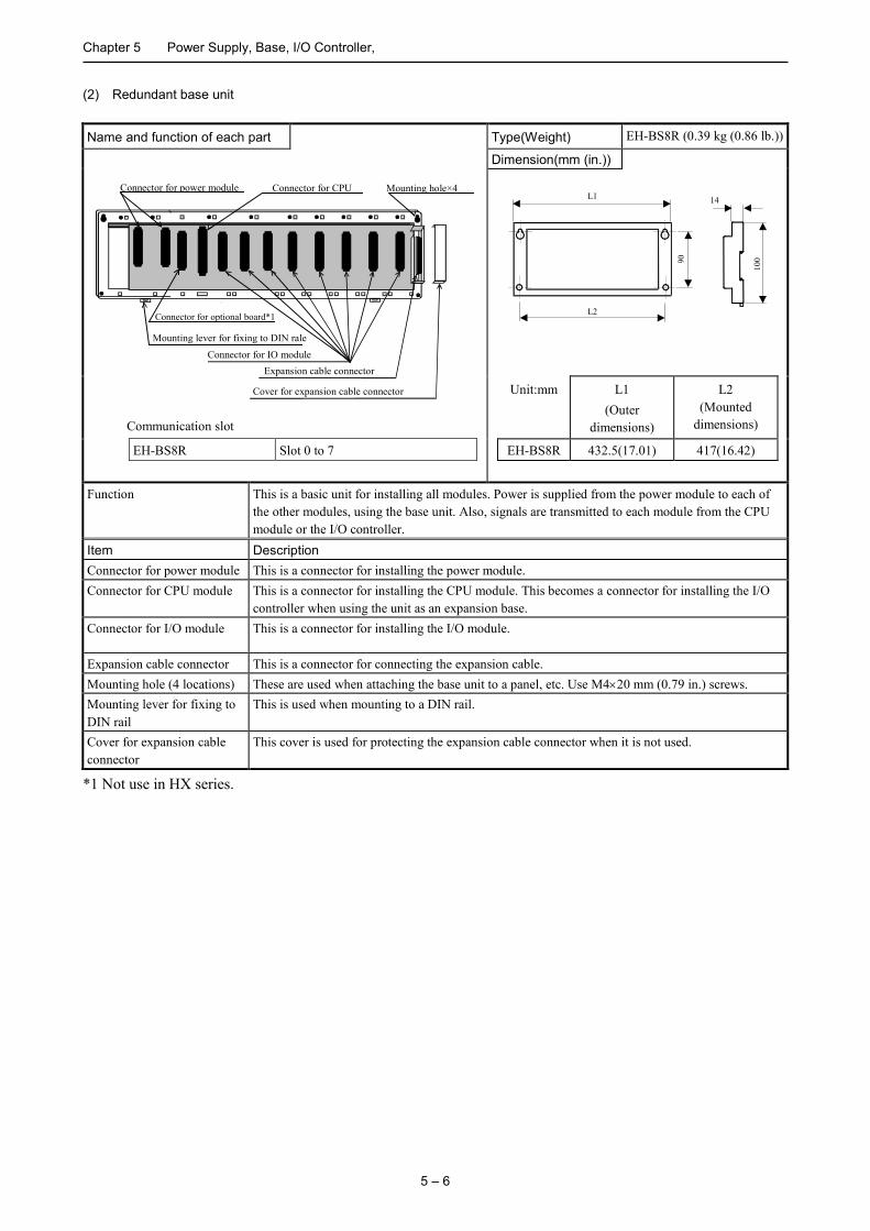
Chapter 5 Power Supply, Base, I/O Controller,
5 – 6
(2) Redundant base unit
Name and function of each part Type(Weight) EH-BS8R (0.39 kg (0.86 lb.))
Dimension(mm (in.))
L1
100
14
L2
90
Communication slot
Unit:mm L1 (Outer
dimensions)
L2 (Mounted
dimensions)
EH-BS8R Slot 0 to 7 EH-BS8R 432.5(17.01) 417(16.42)
Function This is a basic unit for installing all modules. Power is supplied from the power module to each of the other modules, using the base unit. Also, signals are transmitted to each module from the CPU module or the I/O controller.
Item Description Connector for power module This is a connector for installing the power module. Connector for CPU module This is a connector for installing the CPU module. This becomes a connector for installing the I/O
controller when using the unit as an expansion base. Connector for I/O module This is a connector for installing the I/O module.
Expansion cable connector This is a connector for connecting the expansion cable. Mounting hole (4 locations) These are used when attaching the base unit to a panel, etc. Use M4×20 mm (0.79 in.) screws. Mounting lever for fixing to DIN rail
This is used when mounting to a DIN rail.
Cover for expansion cable connector
This cover is used for protecting the expansion cable connector when it is not used.
*1 Not use in HX series.
Connector for CPU Mounting hole×4 Connector for power module
Mounting lever for fixing to DIN rale Connector for IO module
Expansion cable connector
Cover for expansion cable connector
Connector for optional board*1

Chapter 5 Power Supply, Base, I/O Controller
5 – 7
[ Error output, Operation status ] Error output and operation status will be change according to occurrence of error and power ON / OFF as follows.
[ Replacement of fault power supply module ] In case of fault the power supply module, it is possible to replace while operating another power supply module. 1. To easily replace the fault module, install the circuit breaker to each power line. 2. Please replace the fault module as the power off. Please attention the electric shock, because another power supply module is operating. Please design the system of 5V capacity is used as one power supply module when the redundant power supply.
Pow 0 Pow1 Operation status
Input %IX*.0
* is variable depending on the mounting
situations of the module..
FFB0 FFB1
FFB0
FFB1
Operation status of Pow 0 %IX*.0
Error output 0
Error output 1
ON OFF
ON OFF
ON: normal OFF :abnormal
ON: normal OFF: abnormal
ON: abnormal OFF: normal
ON: abnormal OFF: normal
Time chart of Error output and Operation status
Both power turn ON The other side power turn ON
Pow0 output trouble occur Pow0 return from trouble
Pow1 return from trouble Pow1 output trouble occur
Operation status of Pow 1 %IX*.1

Chapter 5 Power Supply, Base, I/O Controller,
5 – 8
5.3 I/O Controller
Name and function of each part Type (Weight) EH-IOCH2 (Approx 0.14 kg (0.31 lb.))
Unit No. switch
Expansion cable connector
Lock button
At shipment: 1 Setable range: 1 to 5
Dimensions (mm (in.))
45 (1.77) 95 (3.74)
100
(3.9
4)
Explanation of function I/O controller is a module to output the output signal from the CPU module to the output module mounted on the expansion base unit and to transmit the input signal of the input module to the CPU module. I/O controller is attached adjacent to the power module of the expansion base unit on the right side. For the unit No. switch, please set 1 to 5 from the unit closer to the CPU module in order. Note) - If other than 1 to 5 of the unit No. switch is set, it does not operate normally.
Item Description Lock button Press this button to dismount. Module can be fixed firmly by a screw of
M4 × 10 mm (0.39 in.). Unit No. switch This is a rotary switch for setting the unit No.
Please set 1 to 5 from the unit closer to the CPU module in order. Example) 1 -> 2 -> 3, 2 -> 4 -> 5, 1 -> 3 -> 5 Always turns off the power supply when setting. Take care because it may operate abnormally if the unit No. is not set in order.
Expansion cable connector
This is a connector to connect an expansion cable. Connect with the former base unit using the expansion cable.

6 – 1
Chapter 6 Digital I/O Module
6.1 Outline
(1) The appearance of 16-point I/O module
Name and function of each part
Type
(Weight)
EH-XD8(Approx.0.16 kg(0.35 lb.))
Terminal block cover
Terminal block
EH-XD16, XDL16(Approx.0.16 kg(0.35 lb.))
EH-XDS16(Approx.0.16 kg(0.35 lb.))
EH-XA16,XAH16(Approx.0.18 kg(0.41 lb.))
EH-YT8,EH-YTP8(Approx.0.16 kg(0.35 lb.))
EH-YT16,EH-YTP16(Approx.0.16 kg(0.35 lb.))
EH-YTP16S(Approx.0.16 kg(0.35 lb.))
EH-YR8B(Approx.0.16 kg(0.35 lb.))
EH-YR12(Approx.0.20 kg(0.44 lb.))
EH-YR16,EH-YR16D(Approx.0.24 kg(0.53 lb.))
EH-YS16(Approx.0.23 kg(0.51 lb.))
Dimensions
(mm (in.))
30 (1.18)
100
(3
.94
)
95 (3.74)
Name Description
Terminal block This is a terminal block for connecting the I/O signals. The terminal block can be connected and
disconnected.
The screws for the terminal block are M3 screws. Use a crimp terminal fitting a screw diameter.
The maximum thickness of the cable should be 0.75 mm2. (Use 0.5 mm2 cable when attaching 2 crimp
terminals to the same terminal.)
The recommended crimp terminal is indicated below.
Terminal block cover This is a cover for installing on the terminal block.
A front view of LED Indicated contents
0 1 2 3
DC INPUT EH-XD16
4 5 6 7
8 9 10 11
12 13 14 15
LED of the number that the I/O signal turns on lights up.
EHVの同様の内容を記載願います。
6 (0.24)
6 (0.24)
Unit: mm (in.)
(Recommended)
Take great care on handling
the terminal because it may
fall off if the screw is loose.
7.6
6.4
8.2 M3 screw

Chapter 6 Digital I/O Module
6 – 2
(2) The appearance of 32-point I/O module
Name and function of each part Type
(Weight)
EH-XD32, XDL32 (Approx. 0.15 kg (0.33 lb.))
LED display switch
External wiring connector
ON
OFF
EH-XDS32 (Approx. 0.15 kg (0.33 lb.))
EH-YT32, YTP32 (Approx. 0.15 kg (0.33 lb.))
Dimensions
(mm (in.))
30 (1.18)
100
(3
.94
)
95 (3.74)
LED display switch
External wiring connector
ON
OFF
Type
(Weight)
EH-XD32E, XDL32E (Approx. 0.15 kg (0.33 lb.))
EH-YT32E, YTP32E (Approx. 0.15 kg (0.33 lb.))
Dimensions
(mm (in.))
30 (1.18)
100
(3
.94
)
104 (4.09)
LED display switch
External wiring connector
(Compatible with EM/H-200
series)
ON
OFF
Type
(Weight)
EH-XD32H (Approx. 0.12 kg (0.26 lb.))
EH-YT32H (Approx. 0.12 kg (0.26 lb.))
Dimensions
(mm (in.))
30 (1.18)
100
(3.9
4)
95 (3.74)
Name Specification
LED display switch This switch is used to switch the group to be displayed, in the I/O display.
External wiring connector This is a connector for connecting the I/O signal.

Chapter 6 Digital I/O Module
6 – 3
A front view of LED Indicated contents
0 1 2 3
DC INPUT EH-XD32
4 5 6 7
8 9 10 11
12 13 14 15
+16
LED of the number that the I/O signal turns on lights up.
LED display switch is switched as follows.
Switch LED +16 Display group
OFF No lighting 0 to 15
ON Lighting 16 to 31
(3) The appearance of 64-point I/O module
Name and function of each part Type
(Weight)
EH-XD64 (Approx. 0.14 kg (0.31 lb.))
LED display switch
External wiring connector
SW2 SW1
EH-YT64, YTP64 (Approx. 0.13 kg
(0.29 lb.))
Dimensions
(mm (in.))
30 (1.18)
100
(3
.94
)
95 (3.74)
Item Description
LED display switch This switch is used to switch the group to be displayed, in the I/O display.
External wiring connector This is a connector for connecting the I/O signals.
A front view of LED Indicated contents
0 1 2 3
DC INPUT EH-XD64
4 5 6 7
8 9 10 11
12 13 14 15
16
32
LED of the number that the I/O signal turns on lights up.
LED display switch is switched as follows.
SW1 SW2 LED 16 LED 32 Display group
OFF OFF Non- lighting Non-lighting 0 to 15
ON OFF Lighting Non-lighting 16 to 31
OFF ON Non-lighting Lighting 32 to 47
ON ON Lighting Lighting 48 to 63
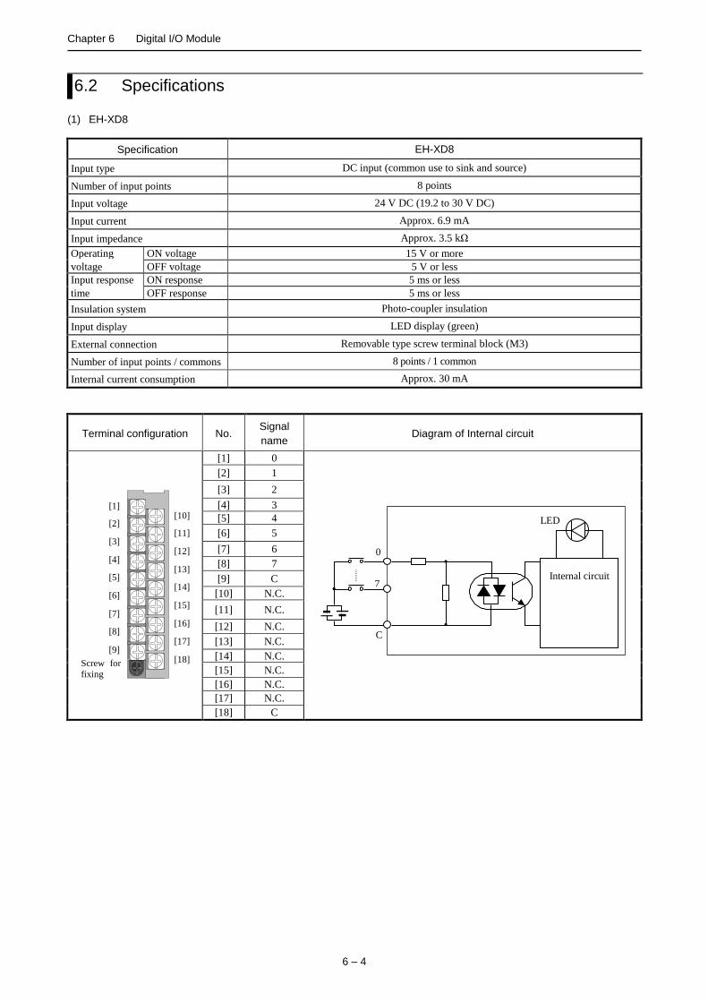
Chapter 6 Digital I/O Module
6 – 4
6.2 Specifications (1) EH-XD8
Specification EH-XD8
Input type DC input (common use to sink and source)
Number of input points 8 points
Input voltage 24 V DC (19.2 to 30 V DC)
Input current Approx. 6.9 mA
Input impedance Approx. 3.5 kΩ
Operating ON voltage 15 V or more
voltage OFF voltage 5 V or less
Input response ON response 5 ms or less
time OFF response 5 ms or less
Insulation system Photo-coupler insulation
Input display LED display (green)
External connection Removable type screw terminal block (M3)
Number of input points / commons 8 points / 1 common
Internal current consumption Approx. 30 mA
Terminal configuration No. Signal
name Diagram of Internal circuit
[1]
[2]
[3]
[4]
[5]
[6]
[7]
[8]
[9]
[10]
[11]
[12]
[13]
[14]
[15]
[16]
[17]
[18] Screw for
fixing
[1] 0
0
C
7
LED
Internal circuit
[2] 1
[3] 2
[4] 3
[5] 4
[6] 5
[7] 6
[8] 7
[9] C
[10] N.C.
[11] N.C.
[12] N.C.
[13] N.C.
[14] N.C.
[15] N.C.
[16] N.C.
[17] N.C.
[18] C

Chapter 6 Digital I/O Module
6 – 5
(2) EH-XD16
Specification EH-XD16
Input type DC input (common use to sink and source)
Number of input points 16 points
Input voltage 24 V DC (19.2 to 30 V DC)
Input current Approx. 4.0 mA
Input impedance Approx. 5.9 kΩ
Operating ON voltage 15 V or more
voltage OFF voltage 5 V or less
Input response ON response 5 ms or less
time OFF response 5 ms or less
Insulation system Photo-coupler insulation
Input display LED display (green)
External connection Removable type screw terminal block (M3)
Number of input points / commons 16 points / 1 common (common terminal is 2 points.)
Internal current consumption Approx. 50 mA
Terminal configuration No. Signal
name Diagram of Internal circuit
[1]
[2]
[3]
[4]
[5]
[6]
[7]
[8]
[9]
[10]
[11]
[12]
[13]
[14]
[15]
[16]
[17]
[18] Screw for
fixing
[1] 0
0
C
15
LED
Internal circuit
[2] 1
[3] 2
[4] 3
[5] 4
[6] 5
[7] 6
[8] 7
[9] C
[10] 8
[11] 9
[12] 10
[13] 11
[14] 12
[15] 13
[16] 14
[17] 15
[18] C

Chapter 6 Digital I/O Module
6 – 6
(3) EH-XDL16
Specification EH-XDL16
Input type DC input (common use to sink and source)
Number of input points 16 points
Input voltage 24 V DC (19.2 to 30 V DC)
Input current Approx. 4.0 mA
Input impedance Approx. 5.9 kΩ
Operating ON voltage 15 V or more
voltage OFF voltage 5 V or less
Input response ON response 16 ms or less
time OFF response 16 ms or less
Insulation system Photo-coupler insulation
Input display LED display (green)
External connection Removable type screw terminal block (M3)
Number of input points / commons 16 points / 1 common (Common terminal is 2 points.)
Internal current consumption Approx. 50 mA
Terminal configuration No. Signal
name Diagram of internal circuit
[1]
[2]
[3]
[4]
[5]
[6]
[7]
[8]
[9]
[10]
[11]
[12]
[13]
[14]
[15]
[16]
[17]
[18] Screw for
fixing
[1] 0
0
C
15
LED
Internal circuit
[2] 1
[3] 2
[4] 3
[5] 4
[6] 5
[7] 6
[8] 7
[9] C
[10] 8
[11] 9
[12] 10
[13] 11
[14] 12
[15] 13
[16] 14
[17] 15
[18] C

Chapter 6 Digital I/O Module
6 – 7
(4) EH-XDS16
Specification EH-XDS16
Input type DC input (common use to sink and source)
Number of input points 16 points
Input voltage 24 V DC (19.2 to 30 V DC)
Input current Approx. 4.0 mA
Input impedance Approx. 5.9 kΩ
Operating
voltage
ON voltage 15 V or more
OFF voltage 5 V or less
Input response
time
ON response 1 ms or less
OFF response 1 ms or less
Insulation system Photo-coupler insulation
Input display LED display (green)
External connection Removable type screw terminal block (M3)
Number of input points / commons 16 points / 1 common (Common terminal is 2 points.)
Internal current consumption Approx. 50 mA
Terminal configuration No. Signal
name Diagram of internal circuit
[1]
[2]
[3]
[4]
[5]
[6]
[7]
[8]
[9]
[10]
[11]
[12]
[13]
[14]
[15]
[16]
[17]
[18] Screw for
fixing
[1] 0
0
C
15
LED
Internal circuit
[2] 1
[3] 2
[4] 3
[5] 4
[6] 5
[7] 6
[8] 7
[9] C
[10] 8
[11] 9
[12] 10
[13] 11
[14] 12
[15] 13
[16] 14
[17] 15
[18] C

Chapter 6 Digital I/O Module
6 – 8
(5) EH-XA16
Specification EH-XA16
Input type AC input
Number of input points 16 points
Input voltage 100 to 120 V AC (85 to 132 V AC)
Input current 4.8 to 7.6 mA (100 V AC / 50Hz)
Input impedance Approx. 16 kΩ (50 Hz) / Approx. 13 kΩ (60 Hz)
Operating ON voltage 79 V AC or more
voltage OFF voltage 20 V AC or less
Input response ON response 15 ms or less
time OFF response 25 ms or less
Insulation system Photo-coupler insulation
Input display LED display (green)
External connection Removable type screw terminal block (M3)
Number of input points / commons 16 points / 1 common (Common terminal is 2 points.)
Internal current consumption Approx. 50 mA
Terminal configuration No. Signal
name Diagram of Internal circuit
[1]
[2]
[3]
[4]
[5]
[6]
[7]
[8]
[9]
[10]
[11]
[12]
[13]
[14]
[15]
[16]
[17]
[18] Screw for
fixing
[1] 0
0
C
15
LED
Internal circuit
[2] 1
[3] 2
[4] 3
[5] 4
[6] 5
[7] 6
[8] 7
[9] C
[10] 8
[11] 9
[12] 10
[13] 11
[14] 12
[15] 13
[16] 14
[17] 15
[18] C

Chapter 6 Digital I/O Module
6 – 9
(6) EH-XAH16
Specification EH-XAH16
Input type AC input
Number of input points 16 points
Input voltage 200 to 240 V AC (170 to 264 V AC)
Input current 4.3 to 8.0 mA (200 V AC / 50 Hz)
Input impedance Approx. 32 kΩ (50 Hz) / Approx. 27 kΩ (60 Hz)
Operating ON voltage 164 V AC or more
voltage OFF voltage 40 V AC or less
Input response ON response 15 ms or less
time OFF response 25 ms or less
Insulation system Photo-coupler insulation
Input display LED display (green)
External connection Removable type screw terminal block (M3)
Number of input points / commons 16 points / 1 common (Common terminal is 2 points.)
Internal current consumption Approx. 50 mA
Terminal configuration No. Signal
name Diagram of Internal circuit
[1]
[2]
[3]
[4]
[5]
[6]
[7]
[8]
[9]
[10]
[11]
[12]
[13]
[14]
[15]
[16]
[17]
[18] Screw for
fixing
[1] 0
0
C
15
LED
Internal circuit
[2] 1
[3] 2
[4] 3
[5] 4
[6] 5
[7] 6
[8] 7
[9] C
[10] 8
[11] 9
[12] 10
[13] 11
[14] 12
[15] 13
[16] 14
[17] 15
[18] C
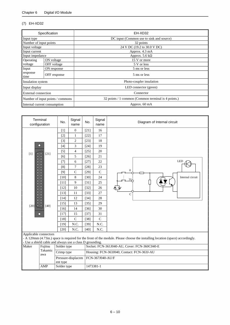
Chapter 6 Digital I/O Module
6 – 10
(7) EH-XD32
Specification EH-XD32
Input type DC input (Common use to sink and source)
Number of input points 32 points
Input voltage 24 V DC (19.2 to 30.0 V DC)
Input current Approx. 4.3 mA
Input impedance Approx. 5.6 kΩ
Operating
voltage
ON voltage 15 V or more
OFF voltage 5 V or less
Input
response
time
ON response 5 ms or less
OFF response 5 ms or less
Insulation system Photo-coupler insulation
Input display LED connector (green)
External connection Connector
Number of input points / commons 32 points / 1 common (Common terminal is 4 points.)
Internal current consumption Approx. 60 mA
Terminal
configuration No.
Signal
name No.
Signal
name Diagram of Internal circuit
[40]
[21]
[20]
[1]
[1] 0 [21] 16
0
C
31
LED
Internal circuit
[2] 1 [22] 17
[3] 2 [23] 18
[4] 3 [24] 19
[5] 4 [25] 20
[6] 5 [26] 21
[7] 6 [27] 22
[8] 7 [28] 23
[9] C [29] C
[10] 8 [30] 24
[11] 9 [31] 25
[12] 10 [32] 26
[13] 11 [33] 27
[14] 12 [34] 28
[15] 13 [35] 29
[16] 14 [36] 30
[17] 15 [37] 31
[18] C [38] C
[19] N.C. [39] N.C.
[20] N.C. [40] N.C.
Applicable connectors
- A 120mm (4.73in.) space is required for the front of the module. Please choose the installing location (space) accordingly.
- Use a shield cable and always use a class D grounding.
Maker Fujitsu
Takamiz
awa
Solder type Socket: FCN-361J040-AU, Cover: FCN-360C040-E
Crimp type Housing: FCN-363J040, Contact: FCN-363J-AU
Pressure-displacem
ent type
FCN-367J040-AU/F
AMP Solder type 1473381-1
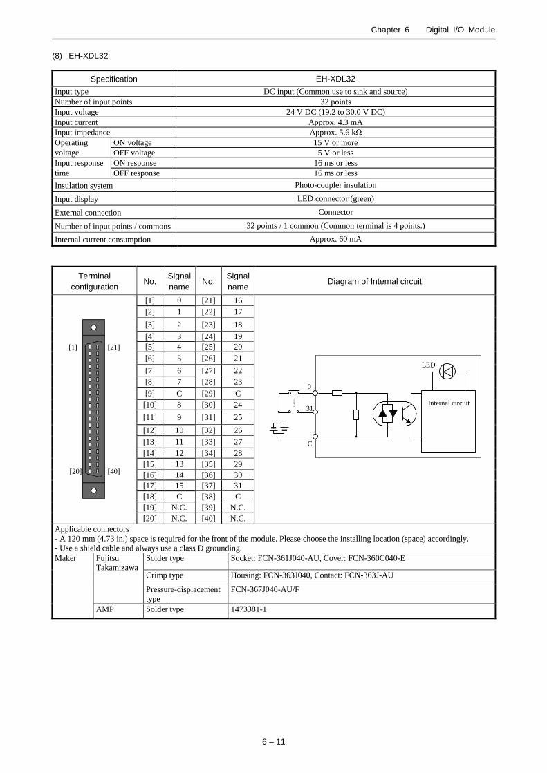
Chapter 6 Digital I/O Module
6 – 11
(8) EH-XDL32
Specification EH-XDL32
Input type DC input (Common use to sink and source)
Number of input points 32 points
Input voltage 24 V DC (19.2 to 30.0 V DC)
Input current Approx. 4.3 mA
Input impedance Approx. 5.6 kΩ
Operating ON voltage 15 V or more
voltage OFF voltage 5 V or less
Input response ON response 16 ms or less
time OFF response 16 ms or less
Insulation system Photo-coupler insulation
Input display LED connector (green)
External connection Connector
Number of input points / commons 32 points / 1 common (Common terminal is 4 points.)
Internal current consumption Approx. 60 mA
Terminal
configuration No.
Signal
name No.
Signal
name Diagram of Internal circuit
[40]
[21]
[20]
[1]
[1] 0 [21] 16
0
C
31
LED
Internal circuit
[2] 1 [22] 17
[3] 2 [23] 18
[4] 3 [24] 19
[5] 4 [25] 20
[6] 5 [26] 21
[7] 6 [27] 22
[8] 7 [28] 23
[9] C [29] C
[10] 8 [30] 24
[11] 9 [31] 25
[12] 10 [32] 26
[13] 11 [33] 27
[14] 12 [34] 28
[15] 13 [35] 29
[16] 14 [36] 30
[17] 15 [37] 31
[18] C [38] C
[19] N.C. [39] N.C.
[20] N.C. [40] N.C.
Applicable connectors
- A 120 mm (4.73 in.) space is required for the front of the module. Please choose the installing location (space) accordingly.
- Use a shield cable and always use a class D grounding.
Maker Fujitsu
Takamizawa
Solder type Socket: FCN-361J040-AU, Cover: FCN-360C040-E
Crimp type Housing: FCN-363J040, Contact: FCN-363J-AU
Pressure-displacement
type
FCN-367J040-AU/F
AMP Solder type 1473381-1

Chapter 6 Digital I/O Module
6 – 12
(9) EH-XDS32
Specification EH-XDS32
Input type DC input (Common use to sink and source)
Number of input points 32 points
Input voltage 24 V DC (19.2 to 30.0 V DC)
Input current Approx. 4.3 mA
Input impedance Approx. 5.6 kΩ
Operating ON voltage 15 V or more
voltage OFF voltage 5 V or less
Input response ON response 1 ms or less
time OFF response 1 ms or less
Insulation system Photo-coupler insulation
Input display LED connector (green)
External connection Connector
Number of input points / commons 32 points / 1 common (Common terminal is 4 points.)
Internal current consumption Approx. 60 mA
Terminal
configuration No.
Signal
name No.
Signal
name Diagram of Internal circuit
[40]
[21]
[20]
[1]
[1] 0 [21] 16
0
C
31
LED
Internal circuit
[2] 1 [22] 17
[3] 2 [23] 18
[4] 3 [24] 19
[5] 4 [25] 20
[6] 5 [26] 21
[7] 6 [27] 22
[8] 7 [28] 23
[9] C [29] C
[10] 8 [30] 24
[11] 9 [31] 25
[12] 10 [32] 26
[13] 11 [33] 27
[14] 12 [34] 28
[15] 13 [35] 29
[16] 14 [36] 30
[17] 15 [37] 31
[18] C [38] C
[19] N.C. [39] N.C.
[20] N.C. [40] N.C.
Applicable connectors
- A 120mm (4.73in.) space is required for the front of the module. Please choose the installing location (space) accordingly.
- Use a shield cable and always use a class D grounding.
Maker Fujitsu
Takamizawa
Solder type Socket: FCN-361J040-AU, Cover: FCN-360C040-E
Crimp type Housing: FCN-363J040, Contact: FCN-363J-AU
Pressure-displacement
type
FCN-367J040-AU/F
AMP Solder type 1473381-1

Chapter 6 Digital I/O Module
6 – 13
(10) EH-XD32E
Specification EH-XD32E
Input type DC input (Common use to sink and source)
Number of input points 32 points
Input voltage 24 V DC (19.2 to 30.0 V DC)
Input current Approx. 4.3 mA
Input impedance Approx. 5.6 kΩ
Operating
voltage
ON voltage 15 V or more
OFF voltage 5 V or less
Input response
time
ON response 1 ms or less
OFF response 1 ms or less
Insulation system Photo-coupler insulation
Input display LED display (green)
External connection Spring type terminal block (removable type)
Number of input points / commons 8 points / 1 common (Common terminal is 2 points each. 4 system common is independent.)
Internal current consumption Approx. 60 mA
Terminal
configuration No.
Signal
name No.
Signal
name Diagram of Internal circuit
[10]
[1]
[11]
[20]
[21]
[30]
[31]
[40]
[1] 0 [21] 16
0
C1
7
LED
Internal circuit
[2] 1 [22] 17
[3] 2 [23] 18
[4] 3 [24] 19
[5] 4 [25] 20
[6] 5 [26] 21
[7] 6 [27] 22
[8] 7 [28] 23
[9] C1 [29] C3
[10] C1 [30] C3
[11] 8 [31] 24
[12] 9 [32] 25
[13] 10 [33] 26
[14] 11 [34] 27
[15] 12 [35] 28
[16] 13 [36] 29
[17] 14 [37] 30
[18] 15 [38] 31
[19] C2 [39] C4
[20] C2 [40] C4
Applicable connectors Applicable cable
Manufacturer: Weidmuller
Type: B2L3.5/20AUOR
Product No.: 175736
0.5 mm2 - 1.0 mm2 (shared at a twisted pair cable and a single core cable)
AWG 28 - 18
A crimp terminal cannot be used.

Chapter 6 Digital I/O Module
6 – 14
(11) EH-XDL32E
Specification EH-XDL32E
Input type DC input (Common use to sink and source)
Number of input points 32 points
Input voltage 24 V DC (19.2 to 30 V DC)
Input current Approx. 4.3 mA
Input impedance Approx. 5.6 kΩ
Operating ON voltage 15 V or more
voltage OFF voltage 5 V or less
Input response ON response 16 ms or less
time OFF response 16 ms or less
Insulation system Photo-coupler insulation
Input display LED display (green)
External connection Spring type terminal block (removable type)
Number of input points / commons 8 points / 1 common (Common terminal is 2 points each. 4 system common is independent.)
Internal current consumption Approx. 60 mA
Terminal
configuration No.
Signal
name No.
Signal
name Diagram of Internal circuit
[10]
[1]
[11]
[20]
[21]
[30]
[31]
[40]
[1] 0 [21] 16
0
C1
7
LED
Internal circuit
[2] 1 [22] 17
[3] 2 [23] 18
[4] 3 [24] 19
[5] 4 [25] 20
[6] 5 [26] 21
[7] 6 [27] 22
[8] 7 [28] 23
[9] C1 [29] C3
[10] C1 [30] C3
[11] 8 [31] 24
[12] 9 [32] 25
[13] 10 [33] 26
[14] 11 [34] 27
[15] 12 [35] 28
[16] 13 [36] 29
[17] 14 [37] 30
[18] 15 [38] 31
[19] C2 [39] C4
[20] C2 [40] C4
Applicable connectors Applicable cable
Manufacturer: Weidmuller
Type: B2L3.5/20AUOR
Product No.175736
0.5 mm2 - 1.0 mm2 (Shared at a twisted pair cable and a single core cable.)
AWG 28 - 18
A crimp terminal cannot be used.

Chapter 6 Digital I/O Module
6 – 15
(12) EH-XD32H
Item EH-XD32H PIM-DM, PIH-DM (for replacing)
Series HX / EH-150 EM / EM-Ⅱ, H-200 / 250 / 252B / 252C
Input specification DC input (Common use to source)
Number of input points 32 points
Input voltage 24 V DC (21.6 to 26.0 V DC)
Input current (24V DC) Approx. 4.1 mA Approx. 4.7 mA
Input impedance Approx. 5.9 k Approx. 5.1 k
Operating ON voltage 19 V or more
voltage OFF voltage 7 V or less
Input
response
time
ON response 4 ms or less
OFF
response 4 ms or less
Insulation system Photo-coupler insulation
Number of input points /
commons 32 points / 1 common (common terminal is 4 *1)
Input display LED (green) *2 LED (red)
polarity Common terminal (+)
External connection Connector (50 pins)
Internal current
consumption
Approx. 60 mA Approx. 20 mA
*1 Common terminals are connected internally.
*2 There are 16 points for each LED display. The displayed group is toggled using a switch.
Specification of external wiring connector Wire
Product name Manufacturer Product No. Connection method
Plug connector Hirose Electric Co., Ltd.
DX30-50P Untie crimping
AWG#30
DX30A-50P AWG#28
DX31-50P Crimping
AWG#30
DX31A-50P AWG#28
DX40-50P Soldering -
Die cast cover DX-50-CV1 - -
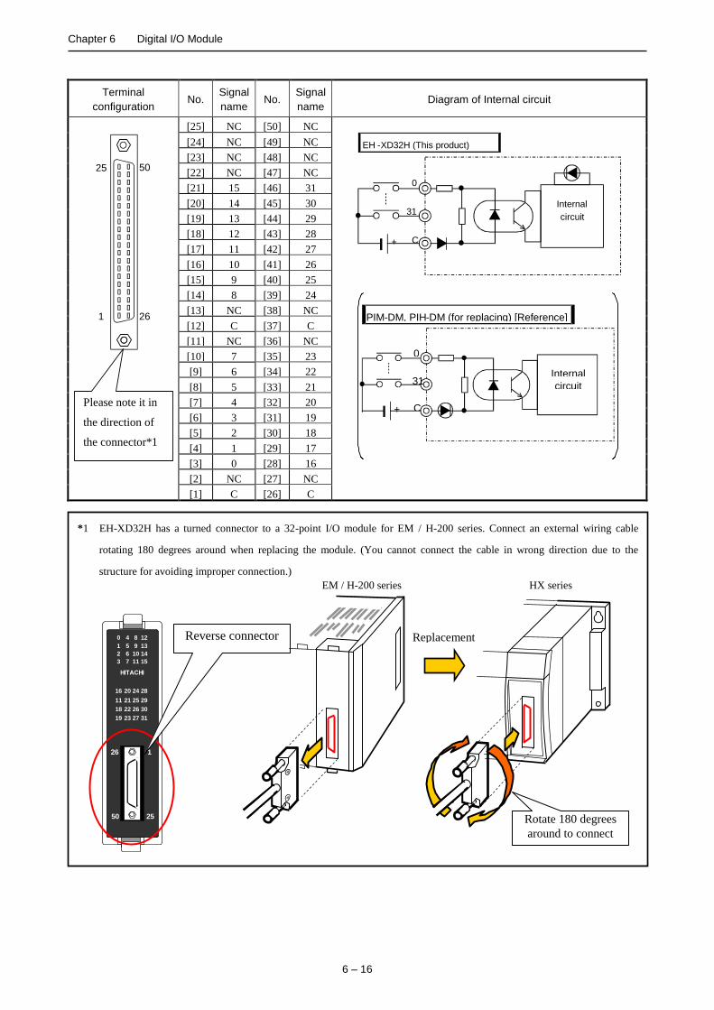
Chapter 6 Digital I/O Module
6 – 16
*1 EH-XD32H has a turned connector to a 32-point I/O module for EM / H-200 series. Connect an external wiring cable
rotating 180 degrees around when replacing the module. (You cannot connect the cable in wrong direction due to the
structure for avoiding improper connection.)
126
2550
120 4 8
131 5 9
142 6 10
153 7 11
2816 20 24
2911 21 25
3018 22 26
3119 23 27
HITACHI
Terminal
configuration No.
Signal
name No.
Signal
name Diagram of Internal circuit
26
50
1
25
Please note it in
the direction of
the connector*1
[25] NC [50] NC
EH - XD32H (This product)
0
31
C
Internal circuit
+
0
31
C
Internal circuit
PIM - DM, PIH - DM (for replacing) [Reference]
+
[24] NC [49] NC
[23] NC [48] NC
[22] NC [47] NC
[21] 15 [46] 31
[20] 14 [45] 30
[19] 13 [44] 29
[18] 12 [43] 28
[17] 11 [42] 27
[16] 10 [41] 26
[15] 9 [40] 25
[14] 8 [39] 24
[13] NC [38] NC
[12] C [37] C
[11] NC [36] NC
[10] 7 [35] 23
[9] 6 [34] 22
[8] 5 [33] 21
[7] 4 [32] 20
[6] 3 [31] 19
[5] 2 [30] 18
[4] 1 [29] 17
[3] 0 [28] 16
[2] NC [27] NC
[1] C [26] C
Reverse connector
Rotate 180 degrees
around to connect
Replacement
EM / H-200 series HX series

Chapter 6 Digital I/O Module
6 – 17
(13) EH-XD64
Specification EH-XD64
Input type DC input (Common used to sink and source)
Number of input points 64 points
Input voltage 24 V DC (19.2 to 30.0 V DC)
Input current Approx. 4.3 mA
Input impedance Approx. 5.6 kΩ
Operating ON voltage 15 V or more
voltage OFF voltage 5 V or less
Input response ON response 1 ms or less
time OFF response 1 ms or less
Insulation system Photo-coupler insulation
Input display LED display (green)*1
External connection Connector
Number of input points / commons 32 points / 1 common
(Common terminal is 4 points each. 2 system common is independent.*2)
Internal current consumption Approx. 80 mA
*1 There are 16 points of LED indication. The indication group is switched by toggle switch. *2 2 groups(C1,C2) are separated. 4 common terminals in one group are connected internally.
Terminal configuration No. Signal
name No.
Signal
name No.
Signal
name No.
Signal
name Diagram of Internal circuit
[20]
[1]
[60]
[41]
[80]
[61] [21]
[40]
C
N
1
C
N
2
[41] 32 [61] 48 [1] 0 [21] 16
0
C1
7
LED
Internal circuit
[42] 33 [62] 49 [2] 1 [22] 17
[43] 34 [63] 50 [3] 2 [23] 18
[44] 35 [64] 51 [4] 3 [24] 19
[45] 36 [65] 52 [5] 4 [25] 20
[46] 37 [66] 53 [6] 5 [26] 21
[47] 38 [67] 54 [7] 6 [27] 22
[48] 39 [68] 55 [8] 7 [28] 23
[49] C2 [69] C2 [9] C1 [29] C1
[50] 40 [70] 56 [10] 8 [30] 24
[51] 41 [71] 57 [11] 9 [31] 25
[52] 42 [72] 58 [12] 10 [32] 26
[53] 43 [73] 59 [13] 11 [33] 27
[54] 44 [74] 60 [14] 12 [34] 28
[55] 45 [75] 61 [15] 13 [35] 29
[56] 46 [76] 62 [16] 14 [36] 30
[57] 47 [77] 63 [17] 15 [37] 31
[58] C2 [78] C2 [18] C1 [38] C1
[59] N.C. [79] N.C. [19] N.C. [39] N.C.
[60] N.C. [80] N.C. [20] N.C. [40] N.C.
Applicable connectors
- A 120 mm (4.73 in.) space is required for the front of the module. Please choose the installing location (space) accordingly.
- Use a shield cable and always use a class D grounding.
Manufacturer Fujitsu
Takamizawa
Solder type Socket: FCN-361J040-AU, Cover: FCN-360C040-E
Crimp type Housing: FCN-363J040, Contact: FCN-363J-AU
Pressure-displacement
type
FCN-367J040-AU/F
AMP Solder type 1473381-1
0 10 20 30 40 50 20
40
60
80
100
24V DC
26.4V DC 28.8V DC
Derating diagram
Ambient temperature (ºC)
ON
rat
e (%
)

Chapter 6 Digital I/O Module
6 – 18
(14) EH-YT8
Specification EH-YT8
Output specification Transistor output (sink type)
Number of output points 8 points
Rated load voltage 12 / 24 V DC (+10 %, -15 %)
Minimum switching current 1 mA
Leak current 0.1 mA
Maximum load
current
1 circuit 0.5 A(0.3 A MFG NO.02F** or before)*1
1 common 2.4 A
Output
response time
OFFON 0.3 ms or less
ONOFF 1 ms or less
Insulation system Photo-coupler insulation
Output display LED display (green)
External connection Removable type screw terminal block (M3)
Number of output points / commons 8 points / 1 common
Surge removal circuit Diode
Fuse*2 4 A / 1 common
External power supply (for supplying
power to S-terminal) 12 / 24 V DC (+10 %, -15 %) (30 mA at the maximum)
Internal current consumption Approx. 30 mA
Short-circuit protection function None
*1 MFG NO. (02F**) indicates products of June 2002.
*2 The module needs to be repaired in case the short-circuited load causes the fuse to blown out.
But, users cannot replace the fuse.
Terminal configuration No. Signal
name Diagram of Internal circuit
[1]
[2]
[3]
[4]
[5]
[6]
[7]
[8]
[9]
[10]
[11]
[12]
[13]
[14]
[15]
[16]
[17]
[18] Screw for
fixing
[1] 0
LED
Internal
circuit
S
0
C
7
[2] 1
[3] 2
[4] 3
[5] 4
[6] 5
[7] 6
[8] 7
[9] C
[10] N.C.
[11] N.C.
[12] N.C.
[13] N.C.
[14] N.C.
[15] N.C.
[16] N.C.
[17] N.C.
[18] S
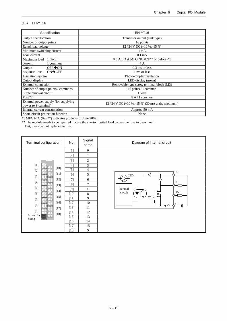
Chapter 6 Digital I/O Module
6 – 19
(15) EH-YT16
Specification EH-YT16
Output specification Transistor output (sink type)
Number of output prints 16 points
Rated load voltage 12 / 24 V DC (+10 %, -15 %)
Minimum switching current 1 mA
Leak current 0.1 mA
Maximum load
current
1 circuit 0.5 A(0.3 A MFG NO.02F** or before)*1
1 common 4 A
Output
response time
OFFON 0.3 ms or less
ONOFF 1 ms or less
Insulation system Photo-coupler insulation
Output display LED display (green)
External connection Removable type screw terminal block (M3)
Number of output points / commons 16 points / 1 common
Surge removal circuit Diode
Fuse*2 8 A / 1 common
External power supply (for supplying
power to S-terminal) 12 / 24 V DC (+10 %, -15 %) (30 mA at the maximum)
Internal current consumption Approx. 50 mA
Short-circuit protection function None
*1 MFG NO. (02F**) indicates products of June 2002.
*2 The module needs to be repaired in case the short-circuited load causes the fuse to blown out.
But, users cannot replace the fuse.
Terminal configuration No. Signal
name Diagram of Internal circuit
[1]
[2]
[3]
[4]
[5]
[6]
[7]
[8]
[9]
[10]
[11]
[12]
[13]
[14]
[15]
[16]
[17]
[18] Screw for
fixing
[1] 0
LED
Internal
circuit
S
0
C
15
[2] 1
[3] 2
[4] 3
[5] 4
[6] 5
[7] 6
[8] 7
[9] C
[10] 8
[11] 9
[12] 10
[13] 11
[14] 12
[15] 13
[16] 14
[17] 15
[18] S

Chapter 6 Digital I/O Module
6 – 20
(16) EH-YTP8
Specification EH-YTP8
Output specification Transistor output (source type)
Number of output points 8 points
Rated load voltage 12 / 24 V DC (+10 %, -15 %)
Minimum switching current 1 mA
Leak current 0.1 mA
Maximum load
current
1 circuit 0.5 A(0.3 A MFG NO.02F** or before)*1
1 common 2.4 A
Output
response time
OFFON 0.3 ms or less
ONOFF 1 ms or less
Insulation system Photo-coupler insulation
Output display LED display (green)
External connection Removal type screw terminal block (M3)
Number of output points / commons 8 points / 1 common
Surge removal circuit Diode
Fuse*2 4 A / 1 common
External power supply (for supplying
power to S-terminal) 12 / 24 V DC (+10 %, -15 %) (30 mA at the maximum)
Internal current consumption Approx. 30 mA
Short-circuit protection function None
*1 MFG NO. (02F**) indicates products of June 2002.
*2 The module needs to be repaired in case the short-circuited load causes the fuse to blown-out.
But, users cannot replace the fuse.
Terminal configuration No. Signal
name Diagram of Internal circuit
[1]
[2]
[3]
[4]
[5]
[6]
[7]
[8]
[9]
[10]
[11]
[12]
[13]
[14]
[15]
[16]
[17]
[18] Screw for
fixing
[1] 0
LED
Internal
circuit
S
0
C
7
[2] 1
[3] 2
[4] 3
[5] 4
[6] 5
[7] 6
[8] 7
[9] C
[10] N.C.
[11] N.C.
[12] N.C.
[13] N.C.
[14] N.C.
[15] N.C.
[16] N.C.
[17] N.C.
[18] S

Chapter 6 Digital I/O Module
6 – 21
(17) EH-YTP16
Specification EH-YTP16
Output specification Transistor output (source type)
Number of output points 16 points
Rated load voltage 12 / 24 V DC (+10 %, -15 %)
Minimum switching current 1 mA
Leak current 0.1 mA
Maximum load
current
1 circuit 0.5 A (0.3 A MFG NO.02F** or before*1)
1 common 4 A
Output
response time
OFFON 0.3 ms or less
ONOFF 1 ms or less
Insulation system Photo-coupler insulation
Output display LED display (green)
External connection Removable type screw terminal block (M3)
Number of output points / commons 16 points / 1 common
Surge removal circuit Diode
Fuse*2 8 A / 1 common
External power supply (for supplying
power to S-terminal) 12 / 24 V DC (+10 %, -15 %) (30 mA at the maximum)
Internal current consumption Approx. 50 mA
Short-circuit protection function None
*1 MFG NO. (02F**) indicates products of June 2002.
*2 The module needs to be repaired in case the short-circuited load causes the fuse to blown out.
But, users cannot replace the fuse.
Terminal configuration No. Signal
name Diagram of Internal circuit
[1]
[2]
[3]
[4]
[5]
[6]
[7]
[8]
[9]
[10]
[11]
[12]
[13]
[14]
[15]
[16]
[17]
[18] Screw for
fixing
[1] 0
LED
Internal
circuit
S
0
C
15
[2] 1
[3] 2
[4] 3
[5] 4
[6] 5
[7] 6
[8] 7
[9] C
[10] 8
[11] 9
[12] 10
[13] 11
[14] 12
[15] 13
[16] 14
[17] 15
[18] S

Chapter 6 Digital I/O Module
6 – 22
(18) EH-YTP16S
Specification EH-YTP16S
Output specification Transistor output (source type)
Number of output points 16 points
Raged load voltage 12 / 24 V DC (+10 %, -15 %)
Minimum switching current 1 mA
Leak current 0.1 mA
Maximum load
current
1 circuit 0.8 A
1 common 5 A
Output
response time
OFFON 0.3 ms or less
ONOFF 1 ms or less
Insulation system Photo-coupler insulation
Output display LED display (green)
External connection Removable type screw terminal block (M3)
Number of output points / commons 16 points / 1 common
Surge removal circuit Built-in
Fuse None
External power supply
(for supplying power to S-terminal) 12 / 24 V DC (+10 %, -15 %) (30 mA at the maximum)
Internal current consumption Approx. 50 mA
Short-circuit protection function Available
Terminal configuration No. Signal
name Diagram of Internal circuit
[1]
[2]
[3]
[4]
[5]
[6]
[7]
[8]
[9]
[10]
[11]
[12]
[13]
[14]
[15]
[16]
[17]
[18] Screw for
fixing
[1] 0
LED
Internal
circuit
S
0
C
15
[2] 1
[3] 2
[4] 3
[5] 4
[6] 5
[7] 6
[8] 7
[9] C
[10] 8
[11] 9
[12] 10
[13] 11
[14] 12
[15] 13
[16] 14
[17] 15
[18] S

Chapter 6 Digital I/O Module
6 – 23
(19) EH-YR8B
Specification EH-YR8B
Output specification Relay output
Number of output points 8 points
Rated load voltage 100 / 240 V AC , 24 V DC
Minimum switching current 1 mA(5 V DC), except after a great current switching
Leak current None
Maximum load
current
1 circuit 2 A
1 common 2 A
Output
response time
OFFON 10 ms or less
ONOFF 10 ms or less
Insulation system Relay insulation
Output display LED display (green)
External connection Removable type screw terminal block (M3)
Number of output points / commons 1 point / 1 common (Each channel is independent.)
Surge removal circuit Varistor (Varistor voltage 423 to 517 V)
Fuse None
External power supply Not used
Internal current consumption (5V DC) Approx. 220 mA
Terminal configuration No. Signal
name Diagram of Internal circuit
[1]
[2]
[3]
[4]
[5]
[6]
[7]
[8]
[9]
[10]
[11]
[12]
[13]
[14]
[15]
[16]
[17]
[18] Screw for
fixing
[1] 0
LED
Internal
circuit
0
C
[2] 1
[3] 2
[4] 3
[5] 4
[6] 5
[7] 6
[8] 7
[9] N.C.
[10] C0
[11] C1
[12] C2
[13] C3
[14] C4
[15] C5
[16] C6
[17] C7
[18] N.C.

Chapter 6 Digital I/O Module
6 – 24
(20) EH-YR12
Specification EH-YR12
Output specification Relay output
Number of output points 12 points
Rated load voltage 100 / 240 V AC, 24 V DC
Minimum switching current 1 mA (5 V DC), except a great current switching
Leak current None
Maximum load
current
1 circuit 2 A
1 common 5 A
Output
response time
OFFON 10 ms or less
ONOFF 10 ms or less
Insulation system Photo-coupler insulation
Output display LED display (green)
External connection Removable type screw terminal block (M3)
Number of output points / commons 12 points / 1 common (Common terminal is 2 points.)
Surge removal circuit None
Fuse None
External power supply 24 V DC (+10 %, -15 %) (70 mA at the maximum)
Internal current consumption (5V DC) Approx. 40 mA
Terminal configuration No. Signal
name Diagram of Internal circuit
[1]
[2]
[3]
[4]
[5]
[6]
[7]
[8]
[9]
[10]
[11]
[12]
[13]
[14]
[15]
[16]
[17]
[18] Screw for
fixing
[1] 24V DC+
LED
24 V DC+
0
C
24 V DC-
11 Internal
circuit
[2] N.C.
[3] 0
[4] 1
[5] 2
[6] 3
[7] 4
[8] 5
[9] C
[10] 24V DC-
[11] N.C.
[12] 6
[13] 7
[14] 8
[15] 9
[16] 10
[17] 11
[18] C

Chapter 6 Digital I/O Module
6 – 25
(21) EH-YR16 / EH-YR16D
Item Specification
Type EH-YR16 EH-YR16D
Output specification Relay output
Rated load voltage 100 / 240 V AC, 24 V DC
Minimum switching current 1 mA
Leak current None
Maximum load 1 circuit 2 A
current 1 common 8 A (Ambient temperature 40 ºC)
See the below derating table
4 A (Ambient temperature 40 ºC)
See the below derating table
Output response OFF ON 10 ms or less
time ON OFF 10 ms or less
Number of output points 16 points / module
Number of common points 16 points / 1 common
(Common terminal is 2)*1
8 points / 1 common
(Common terminal is 2)*2
Surge removal circuit There is no Surge removal circuit and Fuse internal of this module.
Please Install proper device in the each output and / or the common line. Fuse
Insulation system Relay insulation
Output display LED (green)
External connection Removable type screw terminal block (M3)
Internal current consumption (5 V DC) Approximately 430 mA
*1 The common terminals are connected internally.
*2 The common terminals are separated.
Terminal configuration No. Signal name Diagram of Internal circuit
[1]
[2]
[3]
[4]
[5]
[6]
[7]
[8]
[9]
[10]
[11]
[12]
[13]
[14]
[15]
[16]
[17]
[18] Screw for
fixing
YR16 YR16D
C
15
0
5 V DC
Ry
C0
0 8
1
9
C1
EH-YR16 EH-YR16D
C
20 30 40 50 55
Ambient temperature ()
8
7
6
5
4
3
2
1
0
Max
. co
mm
on
cu
rren
t (A
)
EH-YR16
EH-YR16D
3.5 A
Derating table
[1] 0 0
[2] 1 1
[3] 2 2
[4] 3 3
[5] 4 4
[6] 5 5
[7] 6 6
[8] 7 7
[9] C C0
[10] 8 8
[11] 9 9
[12] 10 10
[13] 11 11
[14] 12 12
[15] 13 13
[16] 14 14
[17] 15 15
[18] C C1

Chapter 6 Digital I/O Module
6 – 26
(22) EH-YS16
Specification EH-YS16
Output specification Triac output
Number of output points 16 points
Rated load voltage 100 / 240 V AC (85 to 250 V AC)
Minimum switching current 10 mA
Leak current 2 mA or less
Maximum load
current
1 circuit 0.3 A
1 common 4 A (Ambient temperature 45 C), see the following derating table
Output
response time
OFFON 1 ms or less
ONOFF 1 ms + 1/2 cycle or less
Insulation system Photo-coupler triac insulation
Output display LED display (green)
External connection Removable type screw terminal block (M3)
Number of output points / commons 16 pints / 1 common
Surge removal circuit Varistor
Fuse 6.3 A (Mounting a fuse to external is necessary.)
Internal current consumption Approx. 250 mA
Terminal configuration No. Signal
name Diagram of Internal output
[1]
[2]
[3]
[4]
[5]
[6]
[7]
[8]
[9]
[10]
[11]
[12]
[13]
[14]
[15]
[16]
[17]
[18] Screw for
fixing
[1] 0 LED
Internal
circuit
0
15
C
Tri
gg
er c
ircu
it
Max
imu
m c
om
mo
n c
urr
en
t (A
)
4
3
2
1
0 20 30 40 45 50 55
Ambient temperature (C)
Derating table
[2] 1
[3] 2
[4] 3
[5] 4
[6] 5
[7] 6
[8] 7
[9] C
[10] 8
[11] 9
[12] 10
[13] 11
[14] 12
[15] 13
[16] 14
[17] 15
[18] C

Chapter 6 Digital I/O Module
6 – 27
(23) EH-YT32
Specification EH-YT32
Output specification Transistor output (sink type)
Number of output points 32 points
Rated load voltage 12 / 24 V DC (+10 %, -15 %)
Minimum switching current 1 mA
Leak current 0.1 mA
Maximum load
current
1 circuit 0.2 A
1 common 6.4 A*1
Output
response time
OFFON 0.3 ms or less
ONOFF 1 ms or less
Insulation system Photo-coupler insulation
Output display LED display (green)*2
External connection Connector
Number of output points / commons 32 points / 1 common (Common terminal is 4 points.)
Surge removal circuit Diode
Fuse*3 10 A / 1 common
External power supply
(for supplying power to S-terminal) 12 / 24 V DC (+10 %, -15 %) (30 mA at the maximum)
Internal current consumption (5V DC) Approx. 90 mA
Short-circuit protection function Available*4
*1 Total current of 4 common pins.
For each common pin of a connector, please make common current which is sent into one common pin into 3A or less.
*2 There are 16 points for each LED display. The display group is switched using a switch.
*3 The module needs to be repaired in case a fuse is blown out. But, users cannot replace the fuse.
*4 MFG No.01E** or later are applied.(MFG No.01E** indicates products of May 2001.)
Terminal
configuration No.
Signal
name No.
Signal
name Diagram of Internal circuit
[40]
[21]
[20]
[1]
[1] 0 [21] 16
LED
Internal
circuit
S
0
C
31
[2] 1 [22] 17
[3] 2 [23] 18
[4] 3 [24] 19
[5] 4 [25] 20
[6] 5 [26] 21
[7] 6 [27] 22
[8] 7 [28] 23
[9] C [29] C
[10] S [30] S
[11] 8 [31] 24
[12] 9 [32] 25
[13] 10 [33] 26
[14] 11 [34] 27
[15] 12 [35] 28
[16] 13 [36] 39
[17] 14 [37] 30
[18] 15 [38] 31
[19] C [39] C
[20] S [40] S
Applicable connector
- A 120mm (4.73in.) space is required for the front of the module. Please choose the installing location (space) accordingly.
- Use a shield cable and always use a class D grounding.
Manufacturer Fujitsu
Takamizawa
Solder type Socket: FCN-361J040-AU, Cover: FCN-360C040-E
Crimp type Housing: FCN-363J040, Contact: FCN-363J-AU
Pressure-displacement
type
FCN-367J040-AU/F
AMP Solder type 1473381-1
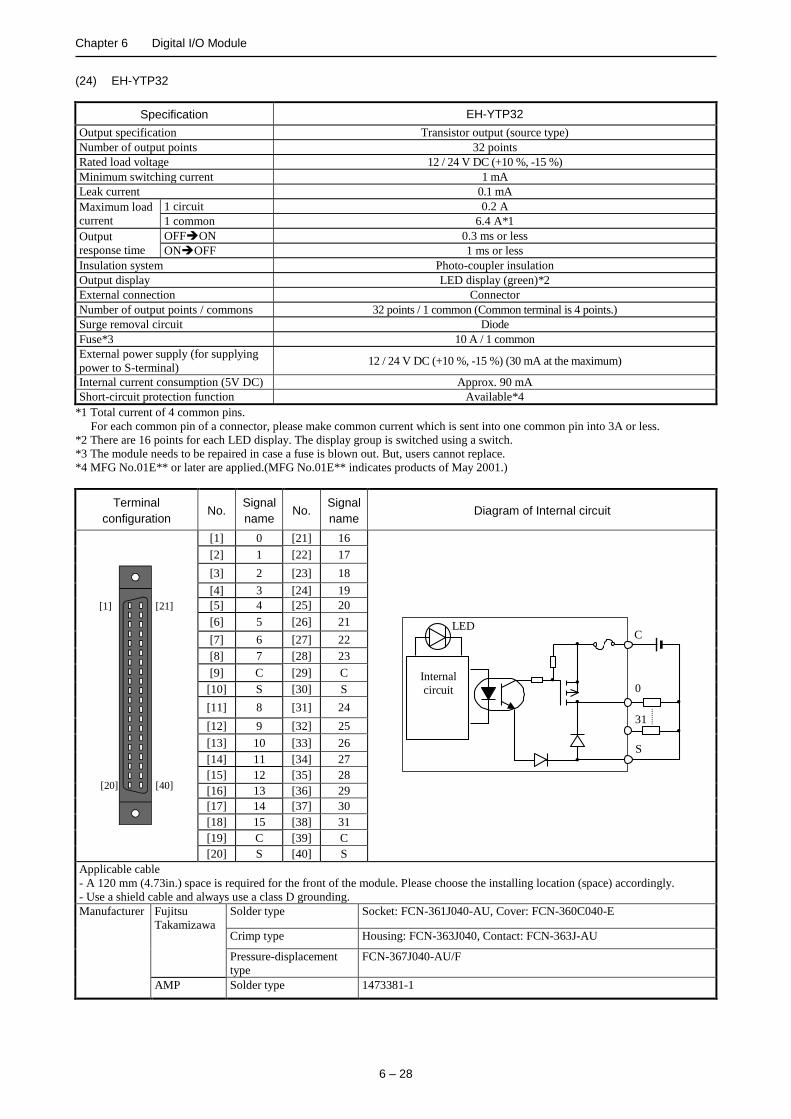
Chapter 6 Digital I/O Module
6 – 28
(24) EH-YTP32
Specification EH-YTP32
Output specification Transistor output (source type)
Number of output points 32 points
Rated load voltage 12 / 24 V DC (+10 %, -15 %)
Minimum switching current 1 mA
Leak current 0.1 mA
Maximum load
current
1 circuit 0.2 A
1 common 6.4 A*1
Output
response time
OFFON 0.3 ms or less
ONOFF 1 ms or less
Insulation system Photo-coupler insulation
Output display LED display (green)*2
External connection Connector
Number of output points / commons 32 points / 1 common (Common terminal is 4 points.)
Surge removal circuit Diode
Fuse*3 10 A / 1 common
External power supply (for supplying
power to S-terminal) 12 / 24 V DC (+10 %, -15 %) (30 mA at the maximum)
Internal current consumption (5V DC) Approx. 90 mA
Short-circuit protection function Available*4
*1 Total current of 4 common pins.
For each common pin of a connector, please make common current which is sent into one common pin into 3A or less.
*2 There are 16 points for each LED display. The display group is switched using a switch.
*3 The module needs to be repaired in case a fuse is blown out. But, users cannot replace.
*4 MFG No.01E** or later are applied.(MFG No.01E** indicates products of May 2001.)
Terminal
configuration No.
Signal
name No.
Signal
name Diagram of Internal circuit
[40]
[21]
[20]
[1]
[1] 0 [21] 16
LED
Internal
circuit
S
0
C
31
[2] 1 [22] 17
[3] 2 [23] 18
[4] 3 [24] 19
[5] 4 [25] 20
[6] 5 [26] 21
[7] 6 [27] 22
[8] 7 [28] 23
[9] C [29] C
[10] S [30] S
[11] 8 [31] 24
[12] 9 [32] 25
[13] 10 [33] 26
[14] 11 [34] 27
[15] 12 [35] 28
[16] 13 [36] 29
[17] 14 [37] 30
[18] 15 [38] 31
[19] C [39] C
[20] S [40] S
Applicable cable
- A 120 mm (4.73in.) space is required for the front of the module. Please choose the installing location (space) accordingly.
- Use a shield cable and always use a class D grounding.
Manufacturer Fujitsu
Takamizawa
Solder type Socket: FCN-361J040-AU, Cover: FCN-360C040-E
Crimp type Housing: FCN-363J040, Contact: FCN-363J-AU
Pressure-displacement
type
FCN-367J040-AU/F
AMP Solder type 1473381-1
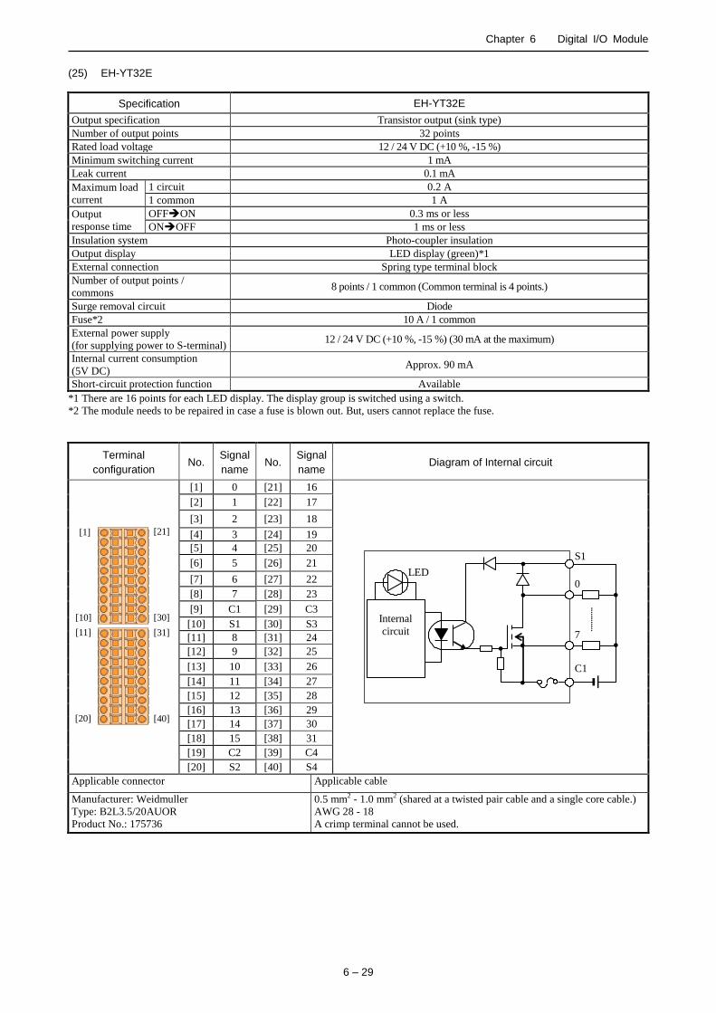
Chapter 6 Digital I/O Module
6 – 29
(25) EH-YT32E
Specification EH-YT32E
Output specification Transistor output (sink type)
Number of output points 32 points
Rated load voltage 12 / 24 V DC (+10 %, -15 %)
Minimum switching current 1 mA
Leak current 0.1 mA
Maximum load
current
1 circuit 0.2 A
1 common 1 A
Output
response time
OFFON 0.3 ms or less
ONOFF 1 ms or less
Insulation system Photo-coupler insulation
Output display LED display (green)*1
External connection Spring type terminal block
Number of output points /
commons 8 points / 1 common (Common terminal is 4 points.)
Surge removal circuit Diode
Fuse*2 10 A / 1 common
External power supply
(for supplying power to S-terminal) 12 / 24 V DC (+10 %, -15 %) (30 mA at the maximum)
Internal current consumption
(5V DC) Approx. 90 mA
Short-circuit protection function Available
*1 There are 16 points for each LED display. The display group is switched using a switch.
*2 The module needs to be repaired in case a fuse is blown out. But, users cannot replace the fuse.
Terminal
configuration No.
Signal
name No.
Signal
name Diagram of Internal circuit
[10]
[1]
[11]
[20]
[21]
[30]
[31]
[40]
[1] 0 [21] 16
LED
Internal
circuit
S1
0
C1
7
[2] 1 [22] 17
[3] 2 [23] 18
[4] 3 [24] 19
[5] 4 [25] 20
[6] 5 [26] 21
[7] 6 [27] 22
[8] 7 [28] 23
[9] C1 [29] C3
[10] S1 [30] S3
[11] 8 [31] 24
[12] 9 [32] 25
[13] 10 [33] 26
[14] 11 [34] 27
[15] 12 [35] 28
[16] 13 [36] 29
[17] 14 [37] 30
[18] 15 [38] 31
[19] C2 [39] C4
[20] S2 [40] S4
Applicable connector Applicable cable
Manufacturer: Weidmuller
Type: B2L3.5/20AUOR
Product No.: 175736
0.5 mm2 - 1.0 mm2 (shared at a twisted pair cable and a single core cable.)
AWG 28 - 18
A crimp terminal cannot be used.

Chapter 6 Digital I/O Module
6 – 30
(26) EH-YTP32E
Specification EH-YTP32E
Output specification Transistor output (source type)
Number of output points 32 points
Rated load voltage 12 / 24 V DC (+10 %, -15 %)
Minimum switching current 1 mA
Leak current 0.1 mA
Maximum load
current
1 circuit 0.2 A
1 common 1 A
Output
response time
OFFON 0.3 ms or less
ONOFF 1 ms or less
Insulation system Photo-coupler insulation
Output display LED display (green)*1
External connection Spring type terminal block
Number of output points / commons 8 points / 1 common (Common terminal is 4 points.)
Surge removal circuit Diode
Fuse*2 10 A / 1 common
External power supply
(for supplying power to S-terminal) 12 / 24 V DC (+10 %, -15 %) (30 mA at the maximum)
Internal current consumption
(5V DC) Approx. 90 mA
Short-circuit protection function Available
*1 There are 16 points for each LED display. The display group is switched using a switch.
*2 The module needs to be repaired in case a fuse is blown out. But, users cannot replace the fuse.
Terminal
configuration No.
Signal
name No.
Signal
name Diagram of Internal circuit
[10]
[1]
[11]
[20]
[21]
[30]
[31]
[40]
[1] 0 [21] 16
LED
Internal
circuit
S1
0
C1
7
[2] 1 [22] 17
[3] 2 [23] 18
[4] 3 [24] 19
[5] 4 [25] 20
[6] 5 [26] 21
[7] 6 [27] 22
[8] 7 [28] 23
[9] C1 [29] C3
[10] S1 [30] S3
[11] 8 [31] 24
[12] 9 [32] 25
[13] 10 [33] 26
[14] 11 [34] 27
[15] 12 [35] 28
[16] 13 [36] 29
[17] 14 [37] 30
[18] 15 [38] 31
[19] C2 [39] C4
[20] S2 [40] S4
Applicable connectors Applicable cable
Manufacturer: Weidmuller
Type: B2L3.5/20AUOR
Product No.: 175736
0.5 mm2 - 1.0 mm2 (shared at a twisted pair cable and a single core cable.
AWG 28 - 18
A crimp terminal cannot be used.

Chapter 6 Digital I/O Module
6 – 31
(27) EH-YT32H
Item EH-YT32H POM-TM, POH-TM (for replacing)
Series HX / EH-150
EM / EM-II, H-200 / 250 / 252
Output specification Transistor output (sink type)
Number of output points 32 points
Rated load voltage 5 / 12 / 24 V DC (5 to 27 V DC)
Minimum switching current 1 mA
Leak current 0.05 mA or less
Maximum output saturation voltage 1 V or less
Maximum 1 point 0.1 A
load current 1 common 0.8 A
A Output OFFON 1 ms or less
response time ONOFF 1 ms or less
Insulation method Photo-coupler insulation
Output display LED (green)*2 LED (red)
External connection Connector (50 pins)
Number of common points 8 points / 1 common
Surge removal circuit Diode (Connecting case of the S terminal)
Fuse*1 2 A / 1 common 1.5 A / 1 common
External power supply*3
(For supplying power to the S terminal)
5 to 27 V DC
(maximum 100 mA)
Internal current consumption (5 V DC) Approx. 90 mA Approx. 70 mA
Short-circuit protection None
*1 The module needs to be repaired in case a load short causes a blown fuse. Further more, it is not allowed for user to replace a
fuse as safety reason.
*2 There are 16 points for each LED display. The display group is toggled using a switch. And, LED display is renewed by
refresh processing.
*3 It is necessary to supply 12 / 24 V DC to the S terminals.
Specification of external wiring connector Wire
Product name Manufacturer Product No. Connection method
Plug connector Hirose Electric Co., Ltd.
DX30-50P Untie crimping
AWG#30
DX30A-50P AWG#28
DX31-50P Crimping
AWG#30
DX31A-50P AWG#28
DX40-50P Soldering -
Die cast cover DX-50-CV1 - -
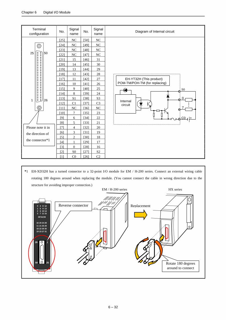
Chapter 6 Digital I/O Module
6 – 32
*1 EH-XD32H has a turned connector to a 32-point I/O module for EM / H-200 series. Connect an external wiring cable
rotating 180 degrees around when replacing the module. (You cannot connect the cable in wrong direction due to the
structure for avoiding improper connection.)
126
2550
120 4 8
131 5 9
142 6 10
153 7 11
2816 20 24
2911 21 25
3018 22 26
3119 23 27
HITACHI
Terminal
configuration No.
Signal
name No.
Signal
name Diagram of Internal circuit
26
50
1
25
Please note it in
the direction of
the connector*1
[25] NC [50] NC
Internal circuit
S0
0
7
C0 +
EH-YT32H (This product)
POM-TM/POH-TM (for replacing)
[24] NC [49] NC
[23] NC [48] NC
[22] NC [47] NC
[21] 15 [46] 31
[20] 14 [45] 30
[19] 13 [44] 29
[18] 12 [43] 28
[17] 11 [42] 27
[16] 10 [41] 26
[15] 9 [40] 25
[14] 8 [39] 24
[13] S1 [38] S3
[12] C1 [37] C3
[11] NC [36] NC
[10] 7 [35] 23
[9] 6 [34] 22
[8] 5 [33] 21
[7] 4 [32] 20
[6] 3 [31] 19
[5] 2 [30] 18
[4] 1 [29] 17
[3] 0 [28] 16
[2] S0 [27] S2
[1] C0 [26] C2
Reverse connector
Rotate 180 degrees
around to connect
Replacement
EM / H-200 series HX series
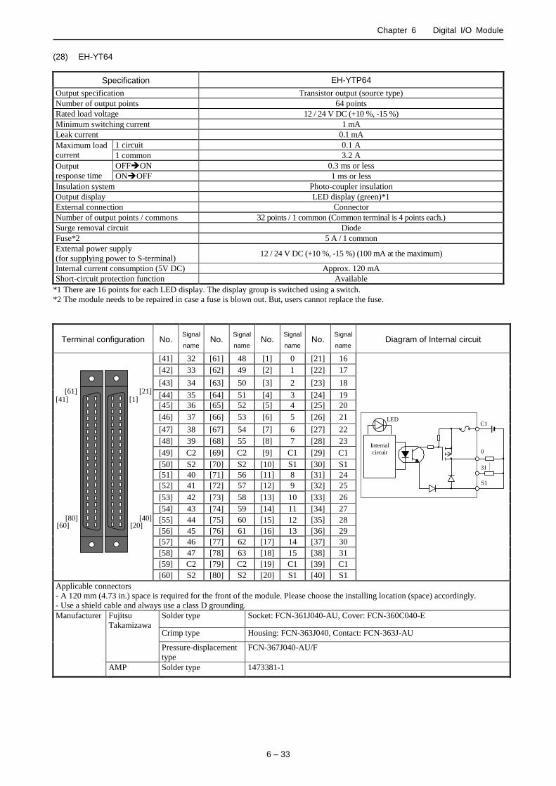
Chapter 6 Digital I/O Module
6 – 33
(28) EH-YT64
Specification EH-YTP64
Output specification Transistor output (source type)
Number of output points 64 points
Rated load voltage 12 / 24 V DC (+10 %, -15 %)
Minimum switching current 1 mA
Leak current 0.1 mA
Maximum load
current
1 circuit 0.1 A
1 common 3.2 A
Output
response time
OFFON 0.3 ms or less
ONOFF 1 ms or less
Insulation system Photo-coupler insulation
Output display LED display (green)*1
External connection Connector
Number of output points / commons 32 points / 1 common (Common terminal is 4 points each.)
Surge removal circuit Diode
Fuse*2 5 A / 1 common
External power supply
(for supplying power to S-terminal) 12 / 24 V DC (+10 %, -15 %) (100 mA at the maximum)
Internal current consumption (5V DC) Approx. 120 mA
Short-circuit protection function Available
*1 There are 16 points for each LED display. The display group is switched using a switch.
*2 The module needs to be repaired in case a fuse is blown out. But, users cannot replace the fuse.
Terminal configuration No. Signal
name No.
Signal
name No.
Signal
name No.
Signal
name Diagram of Internal circuit
[20]
[1]
[60]
[41]
[80]
[61] [21]
[40]
[41] 32 [61] 48 [1] 0 [21] 16
LED
Internal
circuit
S1
0
C1
31
[42] 33 [62] 49 [2] 1 [22] 17
[43] 34 [63] 50 [3] 2 [23] 18
[44] 35 [64] 51 [4] 3 [24] 19
[45] 36 [65] 52 [5] 4 [25] 20
[46] 37 [66] 53 [6] 5 [26] 21
[47] 38 [67] 54 [7] 6 [27] 22
[48] 39 [68] 55 [8] 7 [28] 23
[49] C2 [69] C2 [9] C1 [29] C1
[50] S2 [70] S2 [10] S1 [30] S1
[51] 40 [71] 56 [11] 8 [31] 24
[52] 41 [72] 57 [12] 9 [32] 25
[53] 42 [73] 58 [13] 10 [33] 26
[54] 43 [74] 59 [14] 11 [34] 27
[55] 44 [75] 60 [15] 12 [35] 28
[56] 45 [76] 61 [16] 13 [36] 29
[57] 46 [77] 62 [17] 14 [37] 30
[58] 47 [78] 63 [18] 15 [38] 31
[59] C2 [79] C2 [19] C1 [39] C1
[60] S2 [80] S2 [20] S1 [40] S1
Applicable connectors
- A 120 mm (4.73 in.) space is required for the front of the module. Please choose the installing location (space) accordingly.
- Use a shield cable and always use a class D grounding.
Manufacturer Fujitsu
Takamizawa
Solder type Socket: FCN-361J040-AU, Cover: FCN-360C040-E
Crimp type Housing: FCN-363J040, Contact: FCN-363J-AU
Pressure-displacement
type
FCN-367J040-AU/F
AMP Solder type 1473381-1

Chapter 6 Digital I/O Module
6 – 34
(29) EH-YTP64
Specification EH-YTP64
Output specification Transistor output (source type)
Number of output points 64 points
Rated load voltage 12 / 24 V DC (+10 %, -15 %)
Minimum switching current 1 mA
Leak current 0.1 mA
Maximum load
current
1 circuit 0.1 A
1 common 3.2 A
Output
response time
OFFON 0.3 ms or less
ONOFF 1 ms or less
Insulation system Photo-coupler insulation
Output display LED display (green)*1
External connection Connector
Number of output points / commons 32 points / 1 common (Common terminal is 4 points each.)
Surge removal circuit Diode
Fuse*2 5 A / 1 common
External power supply
(for supplying power to S-terminal) 12 / 24 V DC (+10 %, -15 %) (100 mA at the maximum)
Internal current consumption (5V DC) Approx. 120 mA
Short-circuit protection function Available
*1 There are 16 points for each LED display. The display group is switched using a switch.
*2 The module needs to be repaired in case a fuse is blown out. But, users cannot replace the fuse.
Terminal configuration No. Signal
name No.
Signal
name No.
Signal
name No.
Signal
name Diagram of Internal circuit
[20]
[1]
[60]
[41]
[80]
[61] [21]
[40]
[41] 32 [61] 48 [1] 0 [21] 16
LED
Internal
circuit
S1
0
C1
31
[42] 33 [62] 49 [2] 1 [22] 17
[43] 34 [63] 50 [3] 2 [23] 18
[44] 35 [64] 51 [4] 3 [24] 19
[45] 36 [65] 52 [5] 4 [25] 20
[46] 37 [66] 53 [6] 5 [26] 21
[47] 38 [67] 54 [7] 6 [27] 22
[48] 39 [68] 55 [8] 7 [28] 23
[49] C2 [69] C2 [9] C1 [29] C1
[50] S2 [70] S2 [10] S1 [30] S1
[51] 40 [71] 56 [11] 8 [31] 24
[52] 41 [72] 57 [12] 9 [32] 25
[53] 42 [73] 58 [13] 10 [33] 26
[54] 43 [74] 59 [14] 11 [34] 27
[55] 44 [75] 60 [15] 12 [35] 28
[56] 45 [76] 61 [16] 13 [36] 29
[57] 46 [77] 62 [17] 14 [37] 30
[58] 47 [78] 63 [18] 15 [38] 31
[59] C2 [79] C2 [19] C1 [39] C1
[60] S2 [80] S2 [20] S1 [40] S1
Applicable connectors
- A 120 mm (4.73 in.) space is required for the front of the module. Please choose the installing location (space) accordingly.
- Use a shield cable and always use a class D grounding.
Manufacturer Fujitsu
Takamizawa
Solder type Socket: FCN-361J040-AU, Cover: FCN-360C040-E
Crimp type Housing: FCN-363J040, Contact: FCN-363J-AU
Pressure-displacement
type
FCN-367J040-AU/F
AMP Solder type 1473381-1
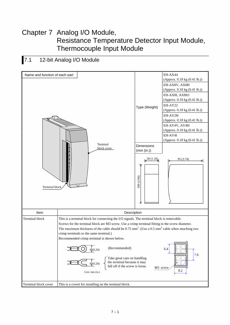
7 – 1
Chapter 7 Analog I/O Module, Resistance Temperature Detector Input Module, Thermocouple Input Module
7.1 12-bit Analog I/O Module
Terminal
block cover
Terminal block
Type (Weight)
EH-AX44
(Approx. 0.18 kg (0.41 lb.))
EH-AX8V, AX8H
(Approx. 0.18 kg (0.41 lb.))
EH-AX8I, AX8IO
(Approx. 0.18 kg (0.41 lb.))
EH-AY22
(Approx. 0.18 kg (0.41 lb.))
EH-AY2H
(Approx. 0.18 kg (0.41 lb.))
EH-AY4V, AY4H
(Approx. 0.18 kg (0.41 lb.))
EH-AY4I
(Approx. 0.18 kg (0.41 lb.))
Dimensions
(mm (in.))
30 (1.18)
100
(3
.94
)
95 (3.74)
Item Description
Terminal block This is a terminal block for connecting the I/O signals. The terminal block is removable.
Screws for the terminal block are M3 screw. Use a crimp terminal fitting to the screw diameter.
The maximum thickness of the cable should be 0.75 mm2. (Use a 0.5 mm2 cable when attaching two
crimp terminals to the same terminal.)
Recommended crimp terminal is shown below.
Terminal block cover This is a covert for installing on the terminal block.
6 (0.24)
6 (0.24)
Unit: mm (in.)
(Recommended)
Take great care on handling
the terminal because it may
fall off if the screw is loose.
7.6
6.4
8.2 M3 screw
Name and function of each part
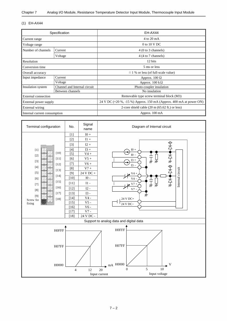
Chapter 7 Analog I/O Module, Resistance Temperature Detector Input Module, Thermocouple Input Module
7 – 2
(1) EH-AX44
Specification EH-AX44
Current range 4 to 20 mA
Voltage range 0 to 10 V DC
Number of channels Current 4 (0 to 3 channels)
Voltage 4 (4 to 7 channels)
Resolution 12 bits
Conversion time 5 ms or less
Overall accuracy ±1 % or less (of full-scale value)
Input impedance Current Approx. 100 Ω
Voltage Approx. 100 kΩ
Insulation system Channel and Internal circuit Photo-coupler insulation
Between channels No insulation
External connection Removable type screw terminal block (M3)
External power supply 24 V DC (+20 %, -15 %) Approx. 150 mA (Approx. 400 mA at power ON)
External wiring 2-core shield cable (20 m (65.62 ft.) or less)
Internal current consumption Approx. 100 mA
Terminal configuration No. Signal
name Diagram of Internal circuit
[1]
[2]
[3]
[4]
[5]
[6]
[7]
[8]
[9]
[10]
[11]
[12]
[13]
[14]
[15]
[16]
[17]
[18] Screw for
fixing
[1] I0 +
Inte
rnal
cir
cuit
24 V DC+
24 V DC-
I0 +
I0 -
I3 +
I3 -
V4 +
V4 -
V7 +
V7 -
[2] I1 +
[3] I2 +
[4] I3 +
[5] V4 +
[6] V5 +
[7] V6 +
[8] V7 +
[9] 24 V DC +
[10] I0 -
[11] I1 -
[12] I2 -
[13] I3 -
[14] V4 -
[15] V5 -
[16] V6 -
[17] V7 -
[18] 24 V DC -
Support to analog data and digital data
H0FFF
H07FF
H0000
4 12 20
Input current
mA
H0FFF
H07FF
H0000
0 5 10
Input voltage
V

Chapter 7 Analog I/O Module, Resistance Temperature Detector Input Module, Thermocouple Input Module
7 – 3
(2) EH-AX8V
Specification EH-AX8V
Current range -
Voltage range 0 to 10 V DC
Number of channels Current -
Voltage 8 (0 to 7 channels)
Resolution 12 bits
Conversion time 5 ms or less
Overall accuracy ±1 % or less (of full-scale value)
Input impedance Current -
Voltage Approx. 100 kΩ
Insulation system Channel and Internal circuit Photo-coupler insulation
Between channels No insulation
External connection Removable type screw terminal block (M3)
External power supply 24 V DC (+20 %, -15 %) Approx. 150 mA (Approx. 400 mA at power ON)
External wiring 2-core shield cable (20 m or less)
Internal current consumption Approx. 100 mA
Terminal configuration No. Signal
name Diagram of Internal circuit
[1]
[2]
[3]
[4]
[5]
[6]
[7]
[8]
[9]
[10]
[11]
[12]
[13]
[14]
[15]
[16]
[17]
[18] Screw for
fixing
[1] V0 +
Inte
rnal
cir
cuit
24 V DC+
24 V DC-
V0 +
V0 -
V7 +
V7 -
[2] V1 +
[3] V2 +
[4] V3 +
[5] V4 +
[6] V5 +
[7] V6 +
[8] V7 +
[9] 24 V DC +
[10] V0 -
[11] V1 -
[12] V2 -
[13] V3 -
[14] V4 -
[15] V5 -
[16] V6 -
[17] V7 -
[18] 24 V DC -
Support to analog data and digital data
H0FFF
H07FF
H0000
0 5 10
Input voltage
V

Chapter 7 Analog I/O Module, Resistance Temperature Detector Input Module, Thermocouple Input Module
7 – 4
(3) EH-AX8H
Specification EH-AX8H
Current range -
Voltage range + / - 10 V DC
Number of channels Current -
Voltage 8 (0 to 7 channels)
Resolution 12 bits
Conversion time 5 ms or less
Overall accuracy ±1 % or less (of full-scale value)
Input impedance Current -
Voltage Approx. 100 kΩ
Insulation system Channel and Internal circuit Photo-coupler insulation
Between channels No insulation
External connection Removable type screw terminal block (M3)
External power supply 24 V DC (+20 %, -15 %) Approx. 150 mA (Approx. 400 mA at power ON)
External wiring 2-core shield cable (20 m or less)
Internal current consumption Approx. 100 mA
Terminal configuration No. Signal
name Diagram of Internal circuit
[1]
[2]
[3]
[4]
[5]
[6]
[7]
[8]
[9]
[10]
[11]
[12]
[13]
[14]
[15]
[16]
[17]
[18] Screw for
fixing
[1] V0 +
Inte
rnal
cir
cuit
24 V DC+
24 V DC-
V0 +
V0 -
V7 +
V7 -
[2] V1 +
[3] V2 +
[4] V3 +
[5] V4 +
[6] V5 +
[7] V6 +
[8] V7 +
[9] 24 V DC +
[10] V0 -
[11] V1 -
[12] V2 -
[13] V3 -
[14] V4 -
[15] V5 -
[16] V6 -
[17] V7 -
[18] 24 V DC -
Support to analog data and digital data
-10
H07FF
H0800
0 +10
Input voltage
V
(A complement of 2)
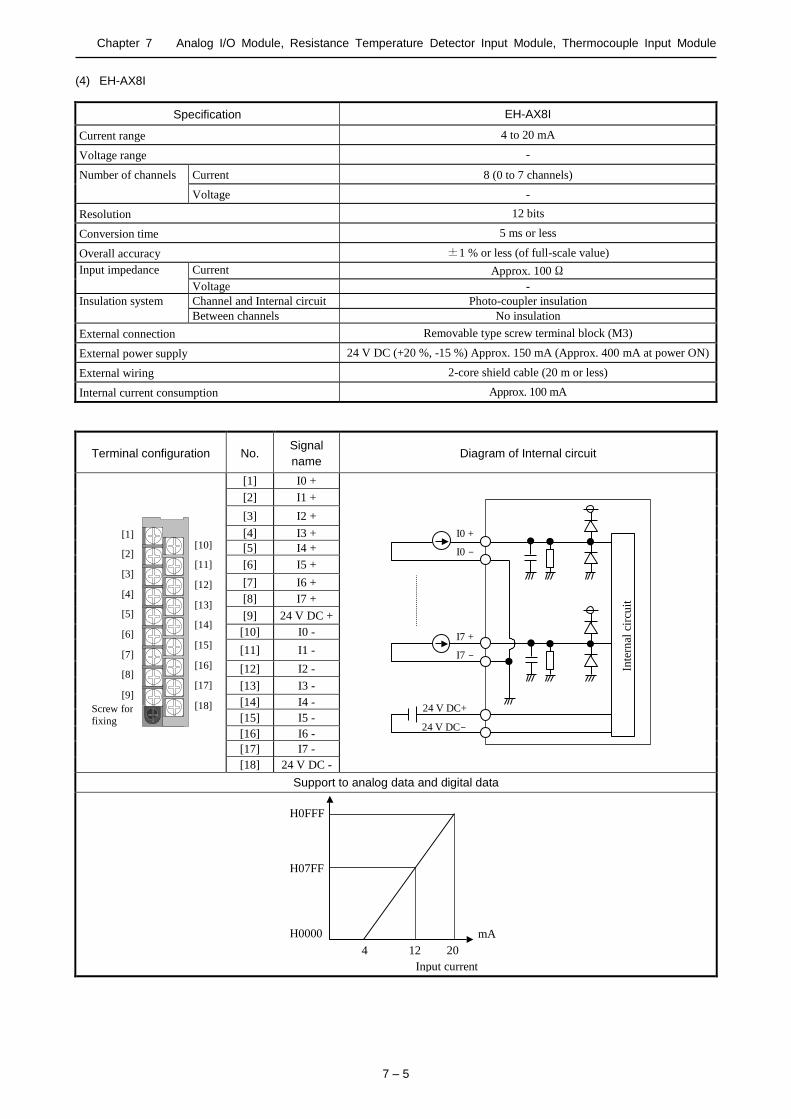
Chapter 7 Analog I/O Module, Resistance Temperature Detector Input Module, Thermocouple Input Module
7 – 5
(4) EH-AX8I
Specification EH-AX8I
Current range 4 to 20 mA
Voltage range -
Number of channels Current 8 (0 to 7 channels)
Voltage -
Resolution 12 bits
Conversion time 5 ms or less
Overall accuracy ±1 % or less (of full-scale value)
Input impedance Current Approx. 100 Ω
Voltage -
Insulation system Channel and Internal circuit Photo-coupler insulation
Between channels No insulation
External connection Removable type screw terminal block (M3)
External power supply 24 V DC (+20 %, -15 %) Approx. 150 mA (Approx. 400 mA at power ON)
External wiring 2-core shield cable (20 m or less)
Internal current consumption Approx. 100 mA
Terminal configuration No. Signal
name Diagram of Internal circuit
[1]
[2]
[3]
[4]
[5]
[6]
[7]
[8]
[9]
[10]
[11]
[12]
[13]
[14]
[15]
[16]
[17]
[18] Screw for
fixing
[1] I0 +
Inte
rnal
cir
cuit
24 V DC+
24 V DC-
I0 +
I0 -
I7 +
I7 -
[2] I1 +
[3] I2 +
[4] I3 +
[5] I4 +
[6] I5 +
[7] I6 +
[8] I7 +
[9] 24 V DC +
[10] I0 -
[11] I1 -
[12] I2 -
[13] I3 -
[14] I4 -
[15] I5 -
[16] I6 -
[17] I7 -
[18] 24 V DC -
Support to analog data and digital data
H0FFF
H07FF
H0000
4 12 20
Input current
mA

Chapter 7 Analog I/O Module, Resistance Temperature Detector Input Module, Thermocouple Input Module
7 – 6
(5) EH-AX8IO
Specification EH-AX8IO
Current range 0 to 22 mA
Voltage range -
Number of channels Current 8 (0 to 7 channels)
Voltage -
Resolution 12 bits
Conversion time 5 ms or less
Overall accuracy ±1% or less (of full-scale value)
Input impedance Current Approx. 100 Ω
Voltage -
Insulation system Channel and Internal circuit Photo-coupler insulation
Between channels No insulation
External connection Removable type screw terminal block (M3)
External power supply 24 V DC (+20 %, -15 %) Approx. 150 mA (Approx. 400 mA at power ON)
External wiring 2-core shield cable (20 m or less)
Internal current consumption Approx. 100 mA
Terminal configuration No. Signal
name Diagram of Internal circuit
[1]
[2]
[3]
[4]
[5]
[6]
[7]
[8]
[9]
[10]
[11]
[12]
[13]
[14]
[15]
[16]
[17]
[18] Screw for
fixing
[1] I0 +
Inte
rnal
cir
cuit
24 V DC+
24 V DC-
I0 +
I0 -
I7 +
I7 -
[2] I1 +
[3] I2 +
[4] I3 +
[5] I4 +
[6] I5 +
[7] I6 +
[8] I7 +
[9] 24 V DC +
[10] I0 -
[11] I1 -
[12] I2 -
[13] I3 -
[14] I4 -
[15] I5 -
[16] I6 -
[17] I7 -
[18] 24 V DC -
Support to analog data and digital data
H0FFF
H07FF
H0000
0 11 22
Input current
mA

Chapter 7 Analog I/O Module, Resistance Temperature Detector Input Module, Thermocouple Input Module
7 – 7
(6) EH-AY22
Specification EH-AY22
Current range 4 to 20 mA
Voltage range 0 to 10 V DC
Number of channels Current 2 (2 to 3 channels)
Voltage 2 (0 to 1 channels)
Resolution 12 bits
Conversion time 5 ms or less
Overall accuracy ±1 % or less (of full-scale value)
External
load resistance
Current 0 to 500 Ω
Voltage 10 kΩ or more
Insulation system Channel and Internal circuit Photo-coupler insulation
Between channels No insulation
External connection Removable type screw terminal block (M3)
External power supply 24 V DC (+20 %, -15 %) Approx. 150 mA (Approx. 500 mA at power ON)
External wiring 2-core shield cable (20 m or less)
Internal current consumption Approx. 100 mA
Terminal configuration No. Signal
name Diagram of Internal circuit
[1]
[2]
[3]
[4]
[5]
[6]
[7]
[8]
[9]
[10]
[11]
[12]
[13]
[14]
[15]
[16]
[17]
[18] Screw for
fixing
[1] V0 +
Inte
rnal
cir
cuit
24 V DC+
24 V DC-
V0 +
V0 -
V1 +
V1 -
I2 +
I2 -
I3 +
I3 -
[2] V1 +
[3] I2 +
[4] I3 +
[5] N.C.
[6] N.C.
[7] N.C.
[8] N.C.
[9] 24 V DC +
[10] V0 -
[11] V1 -
[12] I2 -
[13] I3 -
[14] N.C.
[15] N.C.
[16] N.C.
[17] N.C.
[18] 24 V DC -
Support to analog data and digital data
H0FFF H07FF H0000
4
Ou
tput
curr
ent
(mA
)
12
20
H0FFF H07FF H0000 0
Ou
tput
vo
ltag
e (V
)
5
10

Chapter 7 Analog I/O Module, Resistance Temperature Detector Input Module, Thermocouple Input Module
7 – 8
(7) EH-AY2H
Specification EH-AY2H
Current range -
Voltage range + / - 10 V DC
Number of channels Current -
Voltage 2 (0 to 1 channels)
Resolution 12 bits
Conversion time 5 ms or less
Overall accuracy ±1 % or less (of full-scale value)
External
load resistance
Current -
Voltage 10 kΩor more
Insulation system Channel and Internal circuit Photo-coupler insulation
Between channels No insulation
External connection Removable type screw terminal block (M3)
External power supply 24 V DC (+20 %, -15 %) Approx. 150 mA (Approx. 500 mA at power ON)
External wiring 2-core shield cable (20 m or less)
Internal current consumption Approx. 100 mA
Terminal configuration No. Signal
name Diagram of Internal circuit
[1]
[2]
[3]
[4]
[5]
[6]
[7]
[8]
[9]
[10]
[11]
[12]
[13]
[14]
[15]
[16]
[17]
[18] Screw for
fixing
[1] V0 +
Inte
rnal
cir
cuit
24 V DC+
24 V DC-
V0 +
V0 -
V1 +
V1 -
[2] V1 +
[3] N.C.
[4] N.C.
[5] N.C.
[6] N.C.
[7] N.C.
[8] N.C.
[9] 24 V DC +
[10] V0 -
[11] V1 -
[12] N.C.
[13] N.C.
[14] N.C.
[15] N.C.
[16] N.C.
[17] N.C.
[18] 24 V DC -
Support to analog data and digital data
-10
H07FF
H0800
0
Ou
tput
volt
age V
(A complement of 2)
+10

Chapter 7 Analog I/O Module, Resistance Temperature Detector Input Module, Thermocouple Input Module
7 – 9
(8) EH-AY4I
Specification EH-AY4I
Current range 4 to 20 mA
Voltage range -
Number of channels Current 4 (0 to 3 channels)
Voltage -
Resolution 12 bits
Conversion time 5 ms or less
Overall accuracy ±1 % or less (of full-scale value)
External
load resistance
Current 0 to 350Ω
Voltage -
Insulation system Channel and Internal circuit Photo-coupler insulation
Between channels No insulation
External connection Removable type screw terminal block (M3)
External power supply 24 V DC (+20 %, -15 %) Approx. 150 mA (Approx. 500 mA at power ON)
External wiring 2-core shield cable (20 m or less)
Internal current consumption Approx. 130 mA
Terminal configuration No. Signal
name Diagram of Internal circuit
[1]
[2]
[3]
[4]
[5]
[6]
[7]
[8]
[9]
[10]
[11]
[12]
[13]
[14]
[15]
[16]
[17]
[18] Screw for
fixing
[1] I0 +
Inte
rnal
cir
cuit
24 V DC+
24 V DC-
I0 +
I0 -
I1 +
I1 -
I2 +
I2 -
I3 +
I3 -
[2] I1 +
[3] I2 +
[4] I3 +
[5] N.C.
[6] N.C.
[7] N.C.
[8] N.C.
[9] 24 V DC +
[10] I0 -
[11] I1 -
[12] I2 -
[13] I3 -
[14] N.C.
[15] N.C.
[16] N.C.
[17] N.C.
[18] 24 V DC -
Support to analog data and digital data
H0FFF H07FF H0000
4
Ou
tput
curr
ent
(mA
)
12
20
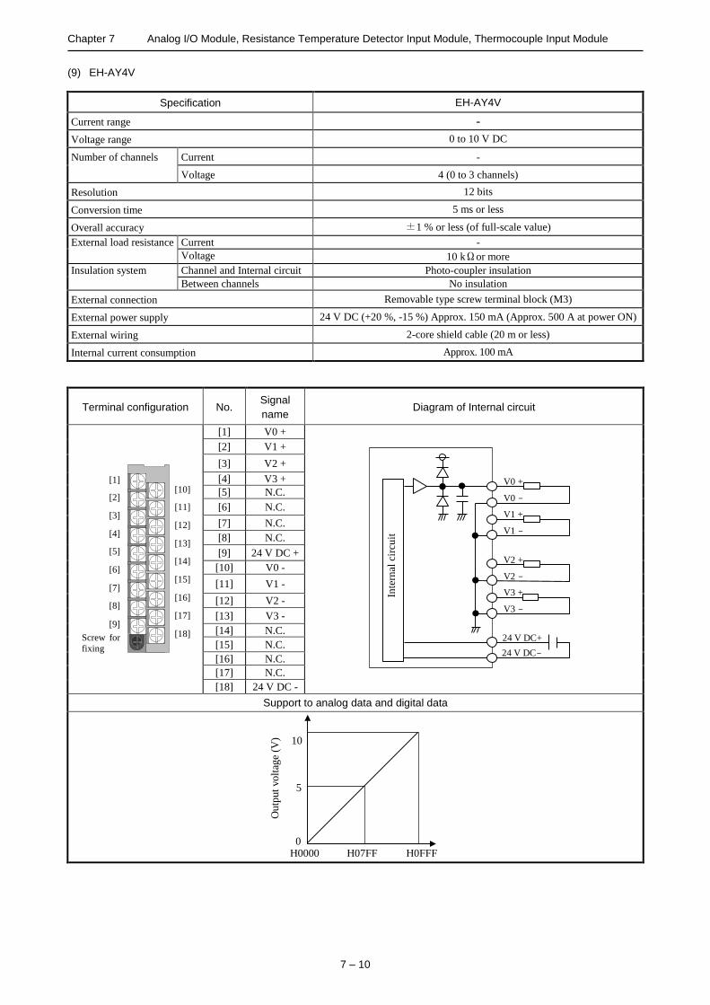
Chapter 7 Analog I/O Module, Resistance Temperature Detector Input Module, Thermocouple Input Module
7 – 10
(9) EH-AY4V
Specification EH-AY4V
Current range -
Voltage range 0 to 10 V DC
Number of channels Current -
Voltage 4 (0 to 3 channels)
Resolution 12 bits
Conversion time 5 ms or less
Overall accuracy ±1 % or less (of full-scale value)
External load resistance Current -
Voltage 10 kΩor more
Insulation system Channel and Internal circuit Photo-coupler insulation
Between channels No insulation
External connection Removable type screw terminal block (M3)
External power supply 24 V DC (+20 %, -15 %) Approx. 150 mA (Approx. 500 A at power ON)
External wiring 2-core shield cable (20 m or less)
Internal current consumption Approx. 100 mA
Terminal configuration No. Signal
name Diagram of Internal circuit
[1]
[2]
[3]
[4]
[5]
[6]
[7]
[8]
[9]
[10]
[11]
[12]
[13]
[14]
[15]
[16]
[17]
[18] Screw for
fixing
[1] V0 +
Inte
rnal
cir
cuit
24 V DC+
24 V DC-
V0 +
V0 -
V1 +
V1 -
V2 +
V2 -
V3 +
V3 -
[2] V1 +
[3] V2 +
[4] V3 +
[5] N.C.
[6] N.C.
[7] N.C.
[8] N.C.
[9] 24 V DC +
[10] V0 -
[11] V1 -
[12] V2 -
[13] V3 -
[14] N.C.
[15] N.C.
[16] N.C.
[17] N.C.
[18] 24 V DC -
Support to analog data and digital data
H0FFF H07FF H0000 0
Ou
tput
vo
ltag
e (V
)
5
10
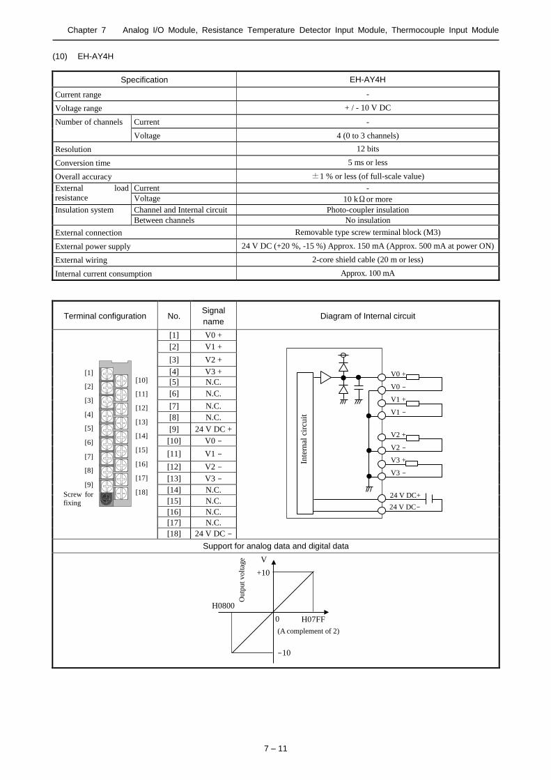
Chapter 7 Analog I/O Module, Resistance Temperature Detector Input Module, Thermocouple Input Module
7 – 11
(10) EH-AY4H
Specification EH-AY4H
Current range -
Voltage range + / - 10 V DC
Number of channels Current -
Voltage 4 (0 to 3 channels)
Resolution 12 bits
Conversion time 5 ms or less
Overall accuracy ±1 % or less (of full-scale value)
External load
resistance
Current -
Voltage 10 kΩor more
Insulation system Channel and Internal circuit Photo-coupler insulation
Between channels No insulation
External connection Removable type screw terminal block (M3)
External power supply 24 V DC (+20 %, -15 %) Approx. 150 mA (Approx. 500 mA at power ON)
External wiring 2-core shield cable (20 m or less)
Internal current consumption Approx. 100 mA
Terminal configuration No. Signal
name Diagram of Internal circuit
[1]
[2]
[3]
[4]
[5]
[6]
[7]
[8]
[9]
[10]
[11]
[12]
[13]
[14]
[15]
[16]
[17]
[18] Screw for
fixing
[1] V0 +
Inte
rnal
cir
cuit
24 V DC+
24 V DC-
V0 +
V0 -
V1 +
V1 -
V2 +
V2 -
V3 +
V3 -
[2] V1 +
[3] V2 +
[4] V3 +
[5] N.C.
[6] N.C.
[7] N.C.
[8] N.C.
[9] 24 V DC +
[10] V0 -
[11] V1 -
[12] V2 -
[13] V3 -
[14] N.C.
[15] N.C.
[16] N.C.
[17] N.C.
[18] 24 V DC -
Support for analog data and digital data
-10
H07FF
H0800
0
Ou
tput
volt
age V
(A complement of 2)
+10

Chapter 7 Analog I/O Module, Resistance Temperature Detector Input Module, Thermocouple Input Module
7 – 12
7.2 14-bit Analog I/O Module
EH-AXH8M
Setting switch
Current and voltage switch
Type (Weight)
EH-AXH8M (Approx. 0.15 kg
(0.34 lb.))
EH-AYH8M (Approx. 0.18 kg
(0.41 lb.))
Dimensions
(mm (in.))
30 (1.18)
10
0 (
3.9
4)
95 (3.74)
EH-AYH8M
Setting switch
Current and
voltage
switch
Name Description
Setting switch Sets the switching of the I/O range, valid / invalid of the input filter, and resolution.
Current and voltage switch Switches current and voltage depending on the range of a setting switch.
Front view of LED Indicating contents
OK
ANAROG IN EH-AXH8M
0 1 2 3
4 5 6 7
OK: Light is on when the module is normal.
0 to 7: Light is off when normal.
[EH-AXH8M]
LED corresponding to the channel flashes if the input becomes 2mA or less when the range is 4 to 22 mA.
(when selecting 0.002 mA resolution.)
[EH-AYH8M]
LED corresponding to the channel flashes if the data outside the output range is set.
Name and function of each part
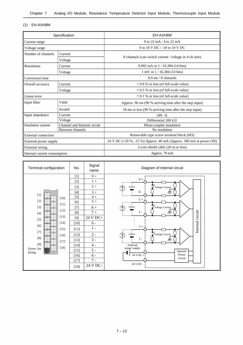
Chapter 7 Analog I/O Module, Resistance Temperature Detector Input Module, Thermocouple Input Module
7 – 13
(1) EH-AXH8M
Specification EH-AXH8M
Current range 0 to 22 mA / 4 to 22 mA
Voltage range 0 to 10 V DC / -10 to 10 V DC
Number of channels Current 8 channels (can switch current / voltage in 4-ch unit)
Voltage
Resolution Current 0.002 mA or 1 / 16,384 (14 bits)
Voltage 1 mV or 1 / 16,384 (14 bits)
Conversion time 8.9 ms / 8 channels
Overall accuracy Current ±0.8 % or less (of full-scale value)
Voltage ±0.5 % or less (of full-scale value)
Linear error ±0.1 % or less (of full-scale value)
Input filter
Valid Approx. 90 ms (90 % arriving time after the step input)
Invalid 18 ms or less (90 % arriving time after the step input)
Input impedance Current 249 Ω
Voltage Differential 200 kΩ
Insulation system Channel and Internal circuit Photo-coupler insulation
Between channels No insulation
External connection Removable type screw terminal block (M3)
External power supply 24 V DC (+20 %, -15 %) Approx. 40 mA (Approx. 300 mA at power ON)
External wiring 2-core shield cable (20 m or less)
Internal current consumption Approx. 70 mA
Terminal configuration No. Signal
name Diagram of Internal circuit
[1]
[2]
[3]
[4]
[5]
[6]
[7]
[8]
[9]
[10]
[11]
[12]
[13]
[14]
[15]
[16]
[17]
[18] Screw for
fixing
[1] 0 +
Internal
Power
circuit 24 V DC +
24 V DC -
Inte
rnal
cir
cuit
0 +
0 -
VoltageCurrent
切替
1 +
1 -
7 +
7 -
External power supply
VoltageCurrent
切替
VoltageCurrent
切替
[2] 1 +
[3] 2 +
[4] 3 +
[5] 4 +
[6] 5 +
[7] 6 +
[8] 7 +
[9] 24 V DC+
[10] 0 -
[11] 1 -
[12] 2 -
[13] 3 -
[14] 4 -
[15] 5 -
[16] 6 -
[17] 7 -
[18] 24 V DC-
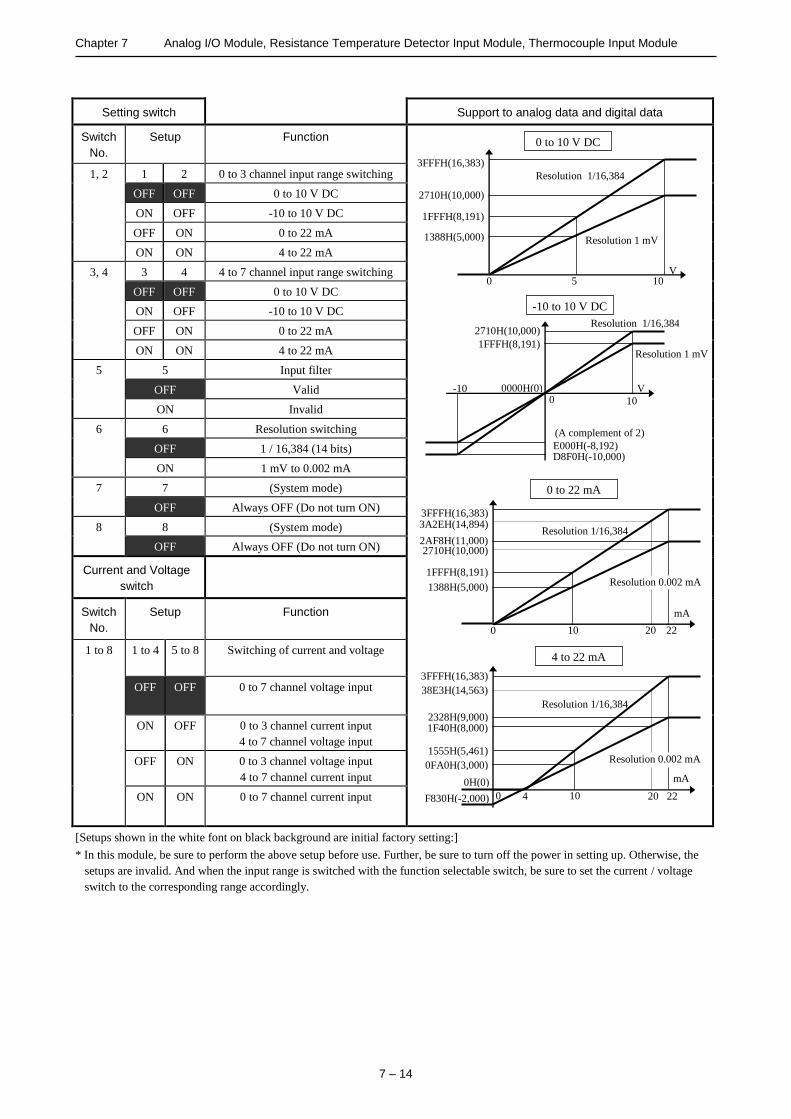
Chapter 7 Analog I/O Module, Resistance Temperature Detector Input Module, Thermocouple Input Module
7 – 14
Setting switch Support to analog data and digital data
Switch
No.
Setup Function
1, 2 1 2 0 to 3 channel input range switching
OFF OFF 0 to 10 V DC
ON OFF -10 to 10 V DC
OFF ON 0 to 22 mA
ON ON 4 to 22 mA
3, 4 3 4 4 to 7 channel input range switching
OFF OFF 0 to 10 V DC
ON OFF -10 to 10 V DC
OFF ON 0 to 22 mA
ON ON 4 to 22 mA
5 5 Input filter
OFF Valid
ON Invalid
6 6 Resolution switching
OFF 1 / 16,384 (14 bits)
ON 1 mV to 0.002 mA
7 7 (System mode)
OFF Always OFF (Do not turn ON)
8 8 (System mode)
OFF Always OFF (Do not turn ON)
Current and Voltage
switch
Switch
No.
Setup Function
1 to 8 1 to 4 5 to 8 Switching of current and voltage
OFF OFF 0 to 7 channel voltage input
ON OFF 0 to 3 channel current input
4 to 7 channel voltage input
OFF ON 0 to 3 channel voltage input
4 to 7 channel current input
ON ON 0 to 7 channel current input
[Setups shown in the white font on black background are initial factory setting:]
* In this module, be sure to perform the above setup before use. Further, be sure to turn off the power in setting up. Otherwise, the
setups are invalid. And when the input range is switched with the function selectable switch, be sure to set the current / voltage
switch to the corresponding range accordingly.
0 to 10 V DC
Resolution 1/16,384
Resolution 1 mV
5 10 V
3FFFH(16,383)
2710H(10,000)
0
1FFFH(8,191)
1388H(5,000)
-10 to 10 V DC
-10 V 0
1FFFH(8,191)
2710H(10,000)
E000H(-8,192) D8F0H(-10,000)
(A complement of 2)
0000H(0)
Resolution 1 mV
10
Resolution 1/16,384
0 to 22 mA
10 22
mA
0
3FFFH(16,383)
2AF8H(11,000)
1FFFH(8,191)
1388H(5,000)
Resolution 1/16,384
20
3A2EH(14,894)
2710H(10,000)
Resolution 0.002 mA
4 to 22 mA
10 22
mA
0 4
3FFFH(16,383)
2328H(9,000)
1555H(5,461)
0FA0H(3,000)
F830H(-2,000)
0H(0)
Resolution 1/16,384
Resolution 0.002 mA
38E3H(14,563)
20
1F40H(8,000)

Chapter 7 Analog I/O Module, Resistance Temperature Detector Input Module, Thermocouple Input Module
7 – 15
(2) EH-AYH8M
Specification EH-AYH8M
Current range 0 to 22 mA / 4 to 22 mA
Voltage range 0 to 10 V DC
Number of
channels
Current 8 channels (can switch current and voltage in 4-ch unit)
Voltage
Resolution Current 0.002 mA or 1 / 16,384 (14 bits)
Voltage 1 mV or 1 / 16,384 (14 bits)
Conversion time 8.9 ms / 8 channels
Overall
accuracy
Current ±0.8 % or less (of full-scale value)
Voltage ±0.8 % or less (of full-scale value)
Linear error ±0.2 % or less (of full-scale value) (range from 0 to 10 V and from 0.05 to 22 mA)
Output filter
Valid Approx. 200 ms or less (90 % arriving time after setting)
Invalid Approx. 18 ms or less (90 % arriving time after setting)
Output
impedance
Current 400 Ωor less
Voltage 10 kΩor less
Insulation
system
Channel and Internal circuit Photo-coupler insulation
Between channels No insulation
External connection Removable type screw terminal block (M3)
External power supply 24 V DC (+20 %, -15 %) Approx. 150 mA (Approx. 400 mA at power ON)
External wiring 2-core shield cable (20 m or less)
Internal current consumption Approx. 70 mA
Terminal configuration No. Signal name Diagram of Internal circuit
[1]
[2]
[3]
[4]
[5]
[6]
[7]
[8]
[9]
[10]
[11]
[12]
[13]
[14]
[15]
[16]
[17]
[18] Screw for
fixing
[1] 0 +
Internal
power
circuit
+ 24 V DC
+
Inte
rnal
cir
cuit
0 +
0 -
1 +
1 -
7 +
7 -
VoltageCurrent
切替
External power supply
- 24 V DC
+
[2] 1 +
[3] 2 +
[4] 3 +
[5] 4 +
[6] 5 +
[7] 6 +
[8] 7 +
[9] 24 V DC+
[10] 0 -
[11] 1 -
[12] 2 -
[13] 3 -
[14] 4 -
[15] 5 -
[16] 6 -
[17] 7 -
[18] 24 V DC-
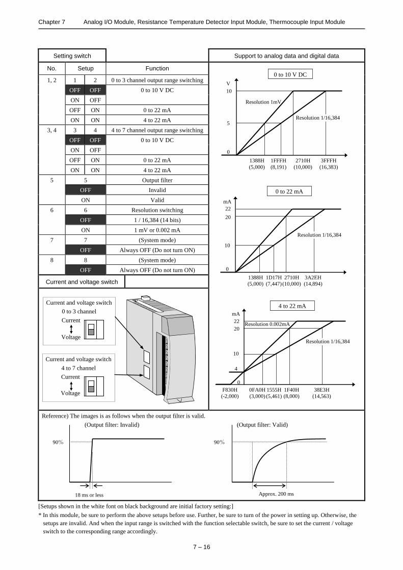
Chapter 7 Analog I/O Module, Resistance Temperature Detector Input Module, Thermocouple Input Module
7 – 16
Setting switch Support to analog data and digital data
No. Setup Function
1, 2 1 2 0 to 3 channel output range switching
OFF OFF 0 to 10 V DC
ON OFF
OFF ON 0 to 22 mA
ON ON 4 to 22 mA
3, 4 3 4 4 to 7 channel output range switching
OFF OFF 0 to 10 V DC
ON OFF
OFF ON 0 to 22 mA
ON ON 4 to 22 mA
5 5 Output filter
OFF Invalid
ON Valid
6 6 Resolution switching
OFF 1 / 16,384 (14 bits)
ON 1 mV or 0.002 mA
7 7 (System mode)
OFF Always OFF (Do not turn ON)
8 8 (System mode)
OFF Always OFF (Do not turn ON)
Current and voltage switch
Reference) The images is as follows when the output filter is valid.
(Output filter: Invalid) (Output filter: Valid)
[Setups shown in the white font on black background are initial factory setting:]
* In this module, be sure to perform the above setups before use. Further, be sure to turn of the power in setting up. Otherwise, the
setups are invalid. And when the input range is switched with the function selectable switch, be sure to set the current / voltage
switch to the corresponding range accordingly.
Resolution 1mV
0 to 10 V DC
10
V
3FFFH
(16,383)
2710H
(10,000)
0
1FFFH
(8,191)
1388H
(5,000)
5
4 to 22 mA
0 to 22 mA
Current and voltage switch
4 to 7 channel
Current
Voltage
Current and voltage switch
0 to 3 channel
Current
Voltage
90%
18 ms or less
90%
Approx. 200 ms
Resolution 1/16,384
10
20
mA
0
3A2EH
(14,894)
2710H
(10,000)
1D17H
(7,447)
1388H
(5,000)
Resolution 1/16,384 Resolution
0.002mA
22
22
mA
0
10
4
38E3H
(14,563)
1F40H
(8,000)
1555H
(5,461)
0FA0H
(3,000)
F830H
(-2,000)
Resolution 1/16,384
Resolution 0.002mA 20
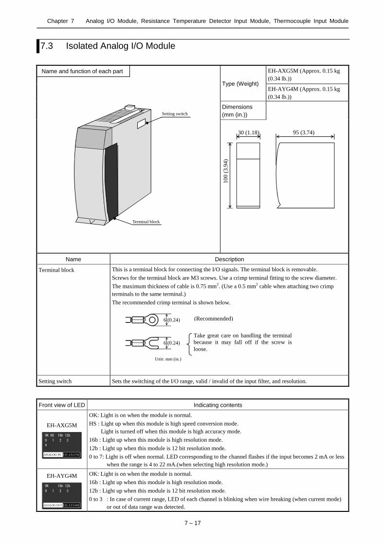
Chapter 7 Analog I/O Module, Resistance Temperature Detector Input Module, Thermocouple Input Module
7 – 17
7.3 Isolated Analog I/O Module
Setting switch
Terminal block
Type (Weight)
EH-AXG5M (Approx. 0.15 kg
(0.34 lb.))
EH-AYG4M (Approx. 0.15 kg
(0.34 lb.))
Dimensions
(mm (in.))
30 (1.18)
10
0 (
3.9
4)
95 (3.74)
Name Description
Terminal block This is a terminal block for connecting the I/O signals. The terminal block is removable.
Screws for the terminal block are M3 screws. Use a crimp terminal fitting to the screw diameter.
The maximum thickness of cable is 0.75 mm2. (Use a 0.5 mm2 cable when attaching two crimp
terminals to the same terminal.)
The recommended crimp terminal is shown below.
Setting switch Sets the switching of the I/O range, valid / invalid of the input filter, and resolution.
Front view of LED Indicating contents
EH-AXG5M
OK HS 16b 12b
ANALOG IN EH-AXG5M
0 1 2 3
4
OK: Light is on when the module is normal.
HS : Light up when this module is high speed conversion mode.
Light is turned off when this module is high accuracy mode.
16b : Light up when this module is high resolution mode.
12b : Light up when this module is 12 bit resolution mode.
0 to 7: Light is off when normal. LED corresponding to the channel flashes if the input becomes 2 mA or less
when the range is 4 to 22 mA.(when selecting high resolution mode.)
EH-AYG4M
OK 16b 12b
ANALOG OUT EH-AYG4M
0 1 2 3
OK: Light is on when the module is normal.
16b : Light up when this module is high resolution mode.
12b : Light up when this module is 12 bit resolution mode.
0 to 3 : In case of current range, LED of each channel is blinking when wire breaking (when current mode)
or out of data range was detected.
6 (0.24)
6 (0.24)
Unit: mm (in.)
(Recommended)
)
Take great care on handling the terminal
because it may fall off if the screw is
loose.
Name and function of each part

Chapter 7 Analog I/O Module, Resistance Temperature Detector Input Module, Thermocouple Input Module
7 – 18
(1) EH-AXG5M
Specification EH-AXG5M
Current range 0 to 22 mA / 4 to 22 mA
Voltage range 0 to 10 V DC / -10 to 10 V DC
Number of channels Current 5 channels (can switch current / voltage)
Voltage
Resolution Current 0 to 64,000, -7,111 to 32,000 or 0 to 4,095 (20 mA)
Voltage 0 to 64,000 or 0 to 4,095
Conversion time 8 ms or 0.25 ms / 5 channels
Overall accuracy*1,*2 At 25 C -0.05 to +0.05 % or less (of full-scale value)
Temperature coefficient -80 to +80 ppm / C or less (of full-scale value)
Absolute maximum ratings Voltage: -15 to 15 V Current :30 mA*3
Input filter 1 kHz
Input impedance Current 249 Ω
Voltage Differential 200 kΩ
Insulation system Channel and Internal circuit Transformer (1,000 V AC, 1 minutes)
Between channels Transformer (1,000 V DC, 1 minutes)
External connection Removable type screw terminal block (M3)
External power supply None
External wiring 2-core shield cable (20 m or less)
Internal current consumption (5 V DC) Approx. 300 mA
*1 Example) Accuracy at 40 C is calculated as follows,
0.05 % (accuracy at 25 C) + 0.008 %/ C (Temperature coefficient) * 15 C (difference form 25 C) = 0.17 %
*2 The accuracy indicates the value after 15 minutes from the power-up. The value may become a lightly higher immediately after
the power-up.
*3 It is the momentary current value that does not destroy the resistance in the module.
Terminal configuration No. Signal
name Diagram of Internal circuit
[1]
[2]
[3]
[4]
[5]
[6]
[7]
[8]
[9]
[10]
[11]
[12]
[13]
[14]
[15]
[16]
[17]
[18] Screw for
fixing
[1] (NC)
[2] (NC)
[3] 0 -
[4] 1 +
[5] 1JP
[6] 2 -
[7] 3 +
[8] 3JP
[9] 4 -
[10] (NC)
[11] 0 +
[12] 0JP
[13] 1 -
[14] 2 +
[15] 2JP
[16] 3 -
[17] 4 +
[18] 4JP
Inte
rnal
cir
cuit
4+
4-
0+
0-
0JP
4JP

Chapter 7 Analog I/O Module, Resistance Temperature Detector Input Module, Thermocouple Input Module
7 – 19
Setting switch Support to analog data and digital data
Switch No.
Setup Function
1, 2 1 2 Input range switching
OFF OFF 0 to 10 V DC
ON OFF -10 to 10 V DC
OFF ON 0 to 22 mA
ON ON 4 to 22 mA
3, 4 3 4 Moving Average data number
OFF OFF Not use moving Average
ON OFF 4
OFF ON 16
ON ON 64
5 5 Resolution
OFF High resolution mode (equally 16 bit)
ON 12 bit mode
6 6 Conversion time
OFF High accuracy, 8 ms (whole channel)
ON High speed,0.25 ms (whole channel)
7 7 For system
OFF Always OFF (should not turn ON)
8 8 For system
OFF Always OFF (should not turn ON)
[Setups shown in the white font on black background are initial
factory setting:]
* In this module, be sure to perform the above setup before use.
Further, be sure to turn off the power in setting up. Otherwise,
the setups are invalid.
0 to 10 V DC
-10 to 10 V DC
4 to 22 mA
0 to 22 mA
5 10
V
FA00H(64,000)
0FFFH(4,095)
0
7D00H(32,000)
07FFH(2,047)
High
resolution
12 bit
resolution
-10
10
V
0
07FFH(2,047)
7D00H(32,000)
F800H(-2,048)
8300H(-32,000)
Signed 16 bits
0000H(0)
FA00H(64,000)
0FFFH(4,095)
20 22
mA
0
E346H(58,182)
20 22 mA
0 4
7D00H(32,000)
6F1CH(28,444)
0FFFH(4,095)
E439H(-7,111)
0H(0)
High
resolution
12 bit
resolution
High
resolution
12 bit
resolution
High
resolution
12 bit
resolution

Chapter 7 Analog I/O Module, Resistance Temperature Detector Input Module, Thermocouple Input Module
7 – 20
(2) EH-AYG4M
Specification EH-AYG4M
Current range 0 to 22 mA / 4 to 22 mA
Voltage range 0 to 10 V DC / -10 to 10 V DC
Number of channels Current 4 channels (can switch current / voltage)
Voltage
Resolution Current 0 to 64,000, -7,111 to 32,000 or 0 to 4,095 (20 mA)
Voltage 0 to 64,000 or 0 to 4,095
Conversion time 0.25 ms / 4 channels
Overall accuracy*1,*2 At 25 C -0.1 to +0.1 % or less (of full-scale value)
Temperature coefficient -80 to +80 ppm / C or less (of full-scale value)
Absolute maximum ratings Voltage: -15 to 15 V Current :24 mA
Output impedance Current More than 1 k Voltage Less than 600
Insulation system Channel and Internal circuit Transformer (1,000 V AC, 1 minutes) Between channels Transformer (1,000 V DC, 1 minutes)
External connection Removable type screw terminal block (M3)
External power supply None
External wiring 2-core shield cable (20 m or less)
Internal current consumption (5 V DC) *3 Max. 730 mA
*1 Example) Accuracy at 40 C is calculated as follows,
0.1 % (accuracy at 25 C) + 0.008 %/ C (Temperature coefficient) * 15 C (difference form 25 C) = 0.22 %
*2 The accuracy indicates the value after 15 minutes from the power-up. The value may become a lightly higher immediately after
the power-up.
*3 480 mA ( All channel output 10 V voltage output with 10 k impedance )
600 mA ( All channel output 10 V voltage output with 1 k impedance ) or ( All channel output 11 mA current output )
730 mA ( All channel output 22 mA current output )
Terminal configuration No. Signal
name Diagram of Internal circuit
[1]
[2]
[3]
[4]
[5]
[6]
[7]
[8]
[9]
[10]
[11]
[12]
[13]
[14]
[15]
[16]
[17]
[18] Screw for
fixing
[1] (NC) [2] (NC)
[3] 0 -
[4] (NC)
[5] 1 -
[6] (NC)
[7] 2 -
[8] (NC)
[9] 3 -
[10] (NC)
[11] V0 +
[12] I0 +
[13] V1 +
[14] I1 +
[15] V2 +
[16] I2 +
[17] V3 +
[18] I3 +
I0+
V0+
0-
Voltage load
1 k to 1 M
Current load
0 to 600
I3+
V3+
3-
Inte
rnal
cir
cuit
* Voltage output and
current output can
not use at the same
time.

Chapter 7 Analog I/O Module, Resistance Temperature Detector Input Module, Thermocouple Input Module
7 – 21
Setting switch Support to analog data and digital data
Switch No.
Setup Function
1, 2 1 2 Output range switching
OFF OFF 0 to 10 V DC
ON OFF -10 to 10 V DC
OFF ON 0 to 22 mA
ON ON 4 to 22 mA
3, 4 3 4 Slew Rate
OFF OFF OFF
ON OFF 0.1 s
OFF ON 1 s
ON ON 10 s
5 5 Resolution
OFF High resolution mode (equally 16 bit)
ON 12 bit mode
6 OFF For system
ON Always OFF (should not turn ON)
7 7 For system
OFF Always OFF (should not turn ON)
8 8 For system
OFF Always OFF (should not turn ON)
Slew Rate function
Slew Rate is a function to change the time of signal change ratio.
It defines the time for the full scale value. The image is as follows.
Example1)
In the case that the signal
setting changes 0 to 5V
[ Mode setting ]
Output range:0 to 10 V DC
Slew Rate :1 s
Example2)
In the case that the signal
setting changes 4 to 22
mA, it is changed to 13
mA before completion of
the setting.
[ Mode setting ]
Output range : 4 to 22 mA
Slew Rate : 10 s
[Setups shown in the white font on black background are initial factory setting:]
* In this module, be sure to perform the above setup before use. Further, be sure to turn off the power in setting up. Otherwise, the
setups are invalid.
10 V
0.5 s
0 V
5 V
1 s
22 mA
4 mA
13 mA
10 s
Set output value 22 mA
Set output value 13 mA
Same ratio
10
V
FA00H
(64,000)
7D00H
(32,000)
0
0FFFH
(4,095)
07FFH
(2,047)
5
FA00H
(64,000)
0FFFH
(4,095)
20
mA
0
E346H
(58,182)
22
0H
(0)
4
7D00H
(32,000)
6F1CH
(28,444)
0FFFH
(4,095)
E439H
(-7,111)
0H
(0)
20
mA
0
22
0 to 10 V DC
High
resolution
12 bit
resolution
-10 to 10 V DC
12 bit
resolution
0 to 22 mA
High
resolution
4 to 22 mA
12 bit
resolution High
resolution
High
resolution
-10
10 V
0 07FFH
(2,047)
7D00H
(32,000)
F800H
(-2,048)
8300H
(-32,000)
Two's complement
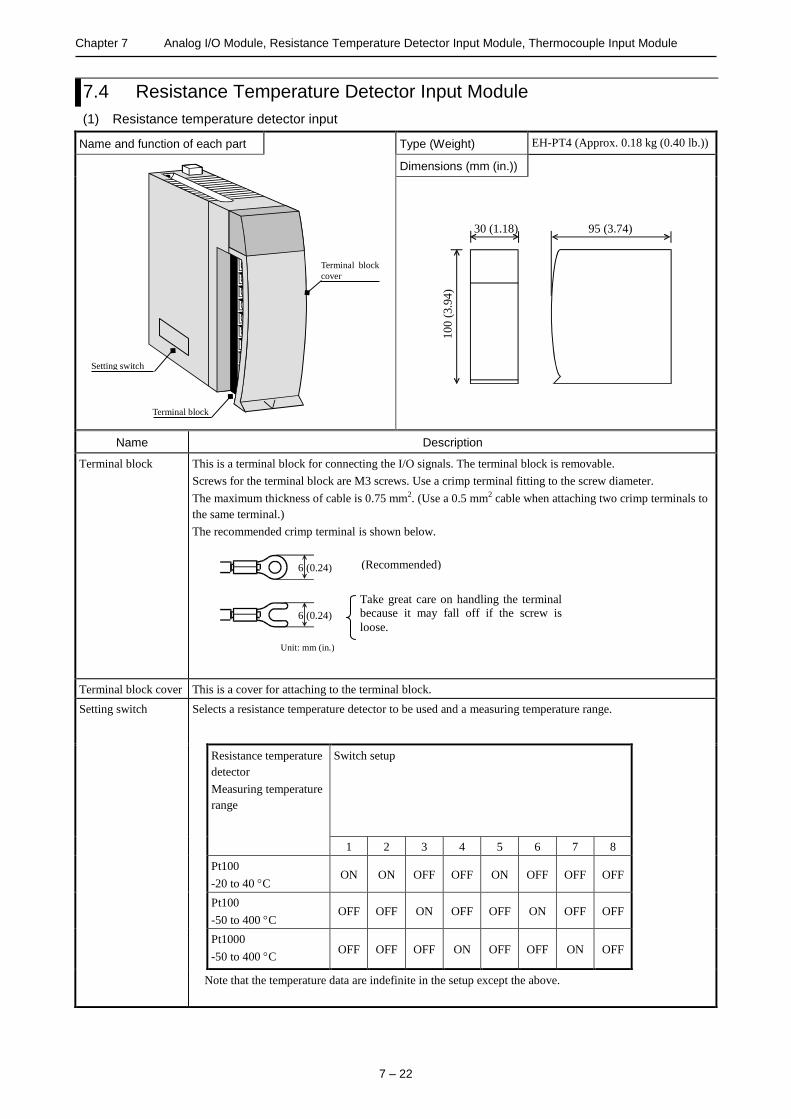
Chapter 7 Analog I/O Module, Resistance Temperature Detector Input Module, Thermocouple Input Module
7 – 22
7.4 Resistance Temperature Detector Input Module
(1) Resistance temperature detector input
Name and function of each part Type (Weight) EH-PT4 (Approx. 0.18 kg (0.40 lb.))
Terminal block
cover
Terminal block
Setting switch
Dimensions (mm (in.))
30 (1.18)
10
0 (
3.9
4)
95 (3.74)
Name Description
Terminal block This is a terminal block for connecting the I/O signals. The terminal block is removable.
Screws for the terminal block are M3 screws. Use a crimp terminal fitting to the screw diameter.
The maximum thickness of cable is 0.75 mm2. (Use a 0.5 mm2 cable when attaching two crimp terminals to
the same terminal.)
The recommended crimp terminal is shown below.
Terminal block cover This is a cover for attaching to the terminal block.
Setting switch Selects a resistance temperature detector to be used and a measuring temperature range.
Resistance temperature
detector
Measuring temperature
range
Switch setup
1 2 3 4 5 6 7 8
Pt100
-20 to 40 C ON ON OFF OFF ON OFF OFF OFF
Pt100
-50 to 400 C OFF OFF ON OFF OFF ON OFF OFF
Pt1000
-50 to 400 C OFF OFF OFF ON OFF OFF ON OFF
Note that the temperature data are indefinite in the setup except the above.
6 (0.24)
6 (0.24)
Unit: mm (in.)
(Recommended)
)
Take great care on handling the terminal
because it may fall off if the screw is
loose.
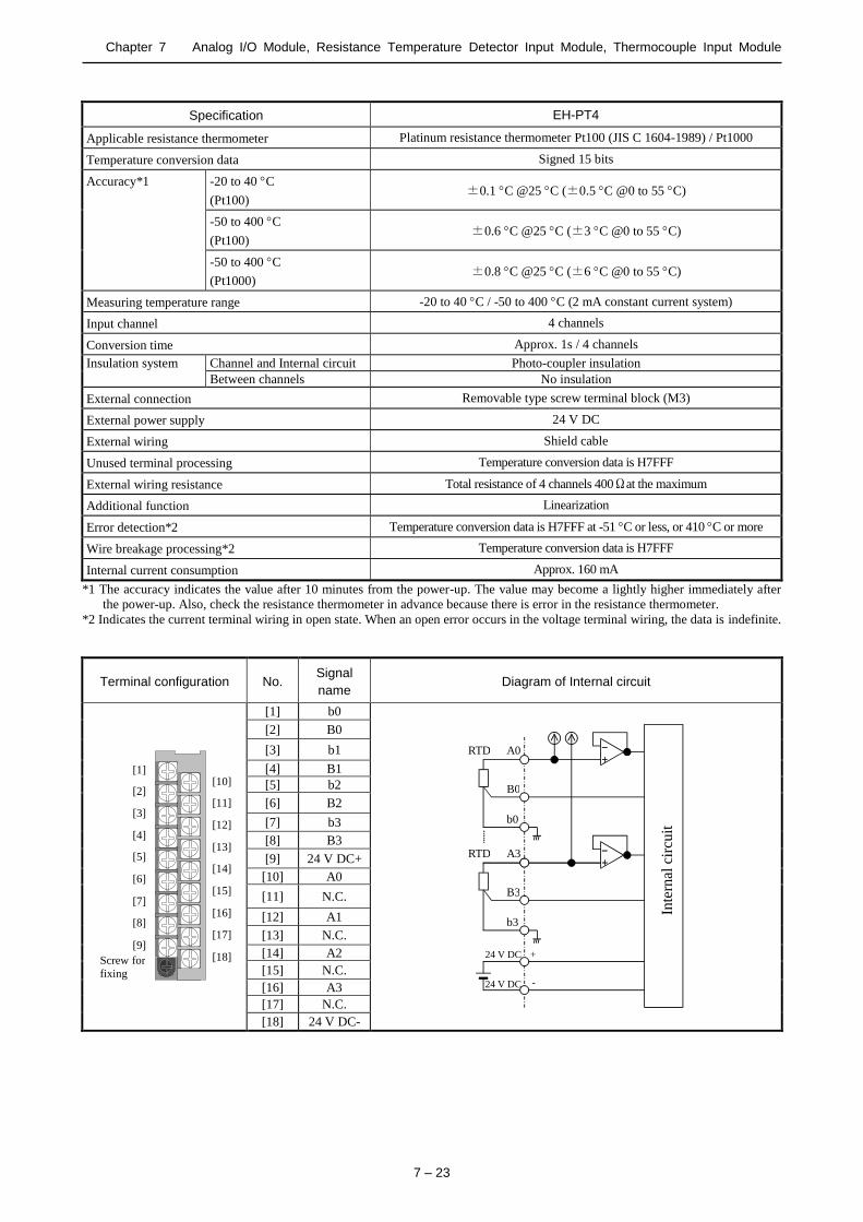
Chapter 7 Analog I/O Module, Resistance Temperature Detector Input Module, Thermocouple Input Module
7 – 23
Specification EH-PT4
Applicable resistance thermometer Platinum resistance thermometer Pt100 (JIS C 1604-1989) / Pt1000
Temperature conversion data Signed 15 bits
Accuracy*1 -20 to 40 C
(Pt100) ±0.1 C @25 C (±0.5 C @0 to 55 C)
-50 to 400 C
(Pt100) ±0.6 C @25 C (±3 C @0 to 55 C)
-50 to 400 C
(Pt1000) ±0.8 C @25 C (±6 C @0 to 55 C)
Measuring temperature range -20 to 40 C / -50 to 400 C (2 mA constant current system)
Input channel 4 channels
Conversion time Approx. 1s / 4 channels
Insulation system Channel and Internal circuit Photo-coupler insulation
Between channels No insulation
External connection Removable type screw terminal block (M3)
External power supply 24 V DC
External wiring Shield cable
Unused terminal processing Temperature conversion data is H7FFF
External wiring resistance Total resistance of 4 channels 400Ωat the maximum
Additional function Linearization
Error detection*2 Temperature conversion data is H7FFF at -51 C or less, or 410 C or more
Wire breakage processing*2 Temperature conversion data is H7FFF
Internal current consumption Approx. 160 mA
*1 The accuracy indicates the value after 10 minutes from the power-up. The value may become a lightly higher immediately after
the power-up. Also, check the resistance thermometer in advance because there is error in the resistance thermometer.
*2 Indicates the current terminal wiring in open state. When an open error occurs in the voltage terminal wiring, the data is indefinite.
Terminal configuration No. Signal
name Diagram of Internal circuit
[1]
[2]
[3]
[4]
[5]
[6]
[7]
[8]
[9]
[10]
[11]
[12]
[13]
[14]
[15]
[16]
[17]
[18] Screw for
fixing
[1] b0
A0
A3
B0
b0
RTD
RTD
B3
b3
24 V DC
24 V DC
Inte
rnal
cir
cuit
- +
- +
+
-
[2] B0
[3] b1
[4] B1
[5] b2
[6] B2
[7] b3
[8] B3
[9] 24 V DC+
[10] A0
[11] N.C.
[12] A1
[13] N.C.
[14] A2
[15] N.C.
[16] A3
[17] N.C.
[18] 24 V DC-

Chapter 7 Analog I/O Module, Resistance Temperature Detector Input Module, Thermocouple Input Module
7 – 24
(2) 6 ch.(3-wire) / 8 ch.(2-wire) resistance temperature detector input
Name and function of each part Model name
(Weight)
EH-RTD8(Approx. 0.15 kg
(0.33 lb.))
Dimensions
(mm (in.))
30 (1.18)
10
0 (
3.9
4)
95 (3.74)
Name Function
Lock button Press this button to dismount. Module can be fixed firmly by a screw of
M4 10 mm (0.39 in.).
I/O cover This is the cover attached to the terminal block area.
Terminal The screws for the terminal block are M3 screws. Use a crimp terminal that fits the screw diameter. The
maximum thickness of the cable should be only up to 0.75 mm2. (Use 0.5 mm2 cable when two crimp terminals
are attached to the same terminal.)
The recommended crimp terminal is indicated below.
6
6
Unit : mm
LED display The status of module and input signal are indicated in this LED.
OK : Green : Normal status
2W : Green : 2-wire mode Off : 3-wire mode
AMB : Green : -40 to 60 C mode Off : -200 to 850 C mode
HS : Green : High speed conversion time (0.5 s)
Off : Normal conversion time (1.6 s)
0 to 7 : Blinking red : Open-wire or out-of-range is detected in corresponding channel number (0.5 s cycle)
Mode
Setting
DIP switch
LED display
I/O cover
Terminal
Lock button
Handle very carefully since cable could be detached when screw is loose.
(Recommended)
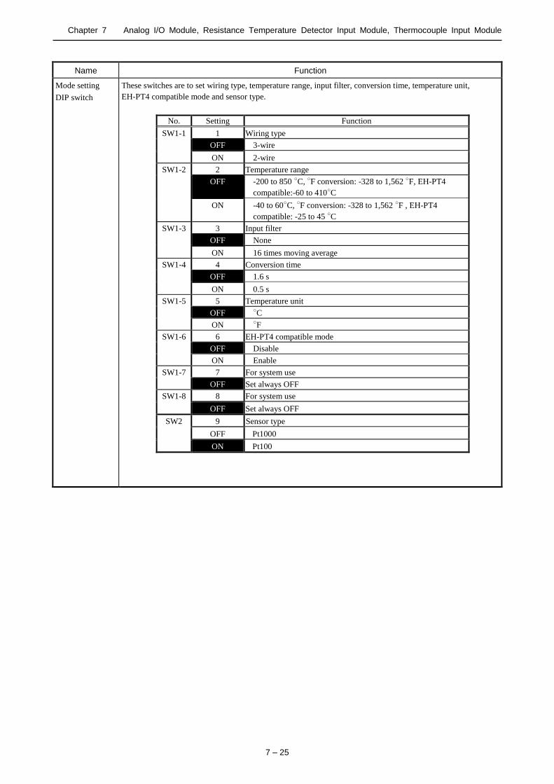
Chapter 7 Analog I/O Module, Resistance Temperature Detector Input Module, Thermocouple Input Module
7 – 25
Name Function
Mode setting
DIP switch
These switches are to set wiring type, temperature range, input filter, conversion time, temperature unit,
EH-PT4 compatible mode and sensor type.
No. Setting Function
SW1-1 1 Wiring type
OFF 3-wire
ON 2-wire
SW1-2 2 Temperature range
OFF -200 to 850 C, F conversion: -328 to 1,562 F, EH-PT4
compatible:-60 to 410C
ON -40 to 60C, F conversion: -328 to 1,562 F , EH-PT4
compatible: -25 to 45 C
SW1-3 3 Input filter
OFF None
ON 16 times moving average
SW1-4 4 Conversion time
OFF 1.6 s
ON 0.5 s
SW1-5 5 Temperature unit
OFF C
ON F
SW1-6 6 EH-PT4 compatible mode
OFF Disable
ON Enable
SW1-7 7 For system use
OFF Set always OFF
SW1-8 8 For system use
OFF Set always OFF
SW2 9 Sensor type
OFF Pt1000
ON Pt100
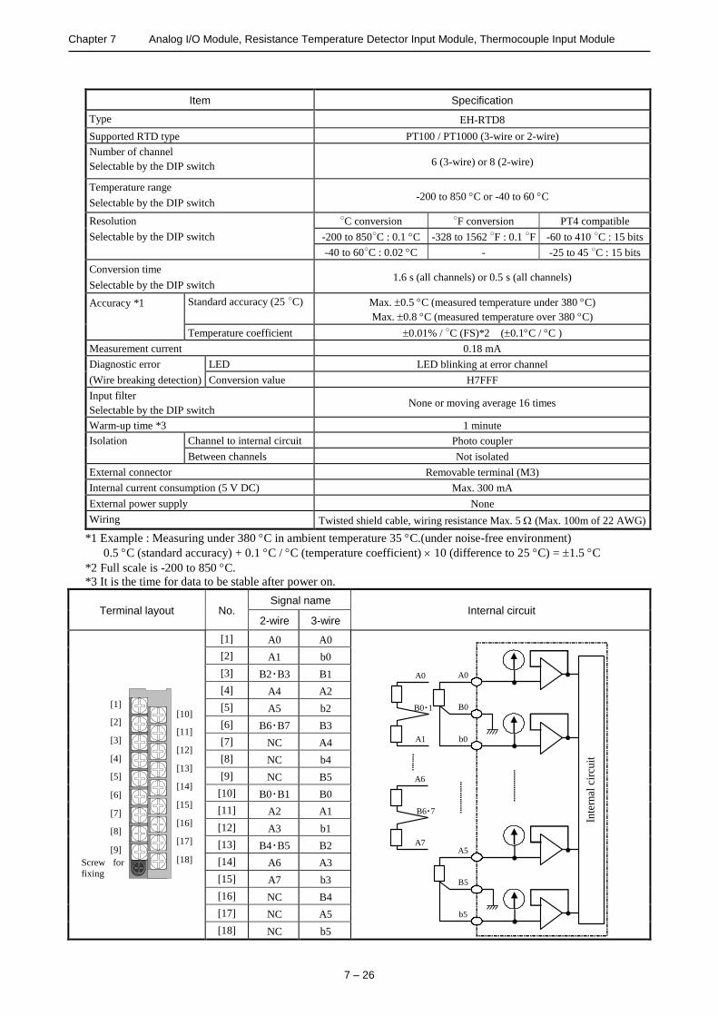
Chapter 7 Analog I/O Module, Resistance Temperature Detector Input Module, Thermocouple Input Module
7 – 26
Item Specification
Type EH-RTD8
Supported RTD type PT100 / PT1000 (3-wire or 2-wire)
Number of channel
Selectable by the DIP switch 6 (3-wire) or 8 (2-wire)
Temperature range
Selectable by the DIP switch -200 to 850 C or -40 to 60 C
Resolution
Selectable by the DIP switch
C conversion F conversion PT4 compatible
-200 to 850C : 0.1 C -328 to 1562 F : 0.1 F -60 to 410 C : 15 bits
-40 to 60C : 0.02 C
0.02
- -25 to 45 C : 15 bits
Conversion time
Selectable by the DIP switch 1.6 s (all channels) or 0.5 s (all channels)
Accuracy *1
Standard accuracy (25 C) Max. 0.5 C (measured temperature under 380 C)
Max. 0.8 C (measured temperature over 380 C)
Temperature coefficient 0.01% / C (FS)*2 (0.1C / C )
Measurement current 0.18 mA
Diagnostic error LED LED blinking at error channel
(Wire breaking detection) Conversion value H7FFF
Input filter
Selectable by the DIP switch None or moving average 16 times
Warm-up time *3 1 minute
Isolation Channel to internal circuit Photo coupler
Between channels Not isolated
External connector Removable terminal (M3)
Internal current consumption (5 V DC) Max. 300 mA
External power supply None
Wiring Twisted shield cable, wiring resistance Max. 5 (Max. 100m of 22 AWG)
*1 Example : Measuring under 380 C in ambient temperature 35 C.(under noise-free environment)
0.5 C (standard accuracy) + 0.1 C / C (temperature coefficient) 10 (difference to 25 C) = 1.5 C
*2 Full scale is -200 to 850 C.
*3 It is the time for data to be stable after power on.
Terminal layout No. Signal name
Internal circuit 2-wire 3-wire
[1]
[2]
[3]
[4]
[5]
[6]
[7]
[8]
[9]
[10]
[11]
[12]
[13]
[14]
[15]
[16]
[17]
[18] Screw for
fixing
[1] A0 A0
A0
b0
B0
A0
A1
B0・1
A5
b5
B5
Inte
rnal
cir
cuit
A6
A7
B6・7
[2] A1 b0
[3] B2・B3 B1
[4] A4 A2
[5] A5 b2
[6] B6・B7 B3
[7] NC A4
[8] NC b4
[9] NC B5
[10] B0・B1 B0
[11] A2 A1
[12] A3 b1
[13] B4・B5 B2
[14] A6 A3
[15] A7 b3
[16] NC B4
[17] NC A5
[18] NC b5

Chapter 7 Analog I/O Module, Resistance Temperature Detector Input Module, Thermocouple Input Module
7 – 27
7.5 Thermocouple Input Module
Name and function of each part Type (Weight) EH-TC8 (Approx. 0.16 kg (0.35 lb.))
Terminal block
cover
Terminal block
Setting switch
Dimensions
(mm (in.))
30 (1.18)
10
0 (
3.9
4)
95 (3.74)
Name Description
Terminal block This is a terminal block for connecting the I/O signals. The terminal block is removable.
Screws for the terminal block are M3 screws. Use a crimp terminal fitting to the screw diameter.
The maximum thickness of cable is 0.75 mm2. (Use 0.5 mm2 cable when attaching two crimp terminals to
the same terminal.)
The recommended crimp terminal is shown below.
Terminal block cover This is a cover for attaching to the terminal block.
Select switch Sets the switching of the temperature range, Celsius / Fahrenheit, etc.
Front view of LED Indicating contents
OK
ANAROG IN EH-AXH8M
0 1 2 3
4 5 6 7
OK: Light is on when the module is normal.
0 to 7: Light is off when normal LED corresponding to the channel which detected the error flashes.
6 (0.24)
6 (0.24)
Unit: mm (in.)
(Recommended)
)
Take great care on handling the terminal
because it may fall off if the screw is
loose.
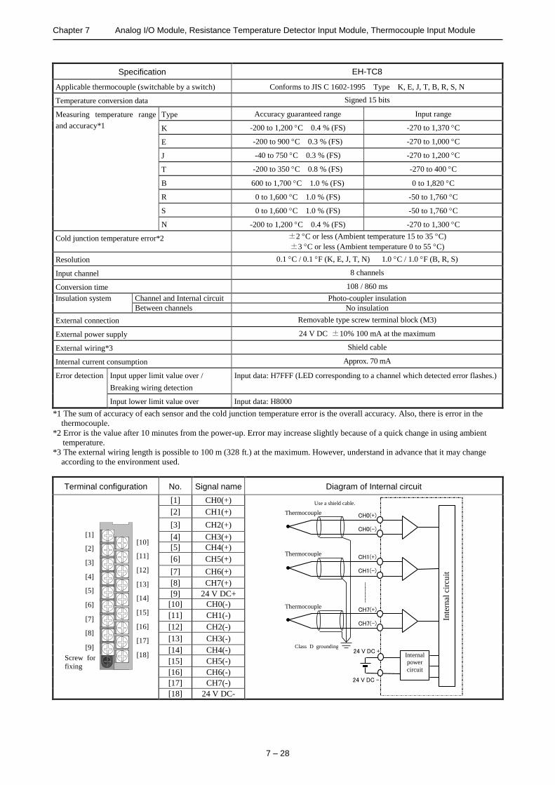
Chapter 7 Analog I/O Module, Resistance Temperature Detector Input Module, Thermocouple Input Module
7 – 28
Specification EH-TC8
Applicable thermocouple (switchable by a switch) Conforms to JIS C 1602-1995 Type K, E, J, T, B, R, S, N
Temperature conversion data Signed 15 bits
Measuring temperature range
and accuracy*1
Type Accuracy guaranteed range Input range
K -200 to 1,200 C 0.4 % (FS) -270 to 1,370 C
E -200 to 900 C 0.3 % (FS) -270 to 1,000 C
J -40 to 750 C 0.3 % (FS) -270 to 1,200 C
T -200 to 350 C 0.8 % (FS) -270 to 400 C
B 600 to 1,700 C 1.0 % (FS) 0 to 1,820 C
R 0 to 1,600 C 1.0 % (FS) -50 to 1,760 C
S 0 to 1,600 C 1.0 % (FS) -50 to 1,760 C
N -200 to 1,200 C 0.4 % (FS) -270 to 1,300 C
Cold junction temperature error*2 ±2 C or less (Ambient temperature 15 to 35 C)
±3 C or less (Ambient temperature 0 to 55 C)
Resolution 0.1 C / 0.1 F (K, E, J, T, N) 1.0 C / 1.0 F (B, R, S)
Input channel 8 channels
Conversion time 108 / 860 ms
Insulation system Channel and Internal circuit Photo-coupler insulation
Between channels No insulation
External connection Removable type screw terminal block (M3)
External power supply 24 V DC ±10% 100 mA at the maximum
External wiring*3 Shield cable
Internal current consumption Approx. 70 mA
Error detection Input upper limit value over /
Breaking wiring detection
Input data: H7FFF (LED corresponding to a channel which detected error flashes.)
Input lower limit value over Input data: H8000
*1 The sum of accuracy of each sensor and the cold junction temperature error is the overall accuracy. Also, there is error in the
thermocouple.
*2 Error is the value after 10 minutes from the power-up. Error may increase slightly because of a quick change in using ambient
temperature.
*3 The external wiring length is possible to 100 m (328 ft.) at the maximum. However, understand in advance that it may change
according to the environment used.
Terminal configuration No. Signal name Diagram of Internal circuit
[1]
[2]
[3]
[4]
[5]
[6]
[7]
[8]
[9]
[10]
[11]
[12]
[13]
[14]
[15]
[16]
[17]
[18] Screw for
fixing
[1] CH0(+)
Internal power
circuit
Thermocouple CH0(+)
CH0(-)
CH1(+)
CH1(-)
24 V DC +
24 V DC -
CH7(+)
CH7(-)
Inte
rnal
cir
cuit
Use a shield cable.
Class D grounding
Thermocouple
Thermocouple
[2] CH1(+)
[3] CH2(+)
[4] CH3(+)
[5] CH4(+)
[6] CH5(+)
[7] CH6(+)
[8] CH7(+)
[9] 24 V DC+
[10] CH0(-)
[11] CH1(-)
[12] CH2(-)
[13] CH3(-)
[14] CH4(-)
[15] CH5(-)
[16] CH6(-)
[17] CH7(-)
[18] 24 V DC-
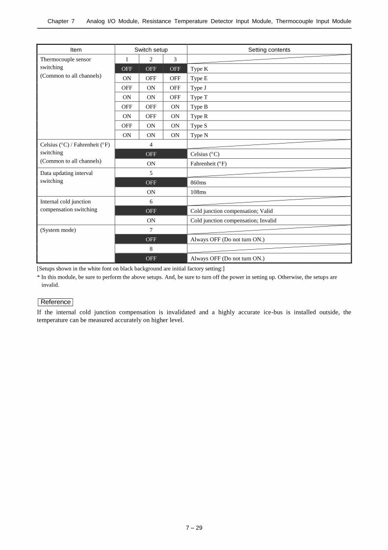
Chapter 7 Analog I/O Module, Resistance Temperature Detector Input Module, Thermocouple Input Module
7 – 29
Item Switch setup Setting contents
Thermocouple sensor
switching
(Common to all channels)
1 2 3
OFF OFF OFF Type K
ON OFF OFF Type E
OFF ON OFF Type J
ON ON OFF Type T
OFF OFF ON Type B
ON OFF ON Type R
OFF ON ON Type S
ON ON ON Type N
Celsius (C) / Fahrenheit (F)
switching
(Common to all channels)
4
OFF Celsius (C)
ON Fahrenheit (F)
Data updating interval
switching
5
OFF 860ms
ON 108ms
Internal cold junction
compensation switching
6
OFF Cold junction compensation; Valid
ON Cold junction compensation; Invalid
(System mode) 7
OFF Always OFF (Do not turn ON.)
8
OFF Always OFF (Do not turn ON.)
[Setups shown in the white font on black background are initial factory setting:]
* In this module, be sure to perform the above setups. And, be sure to turn off the power in setting up. Otherwise, the setups are
invalid.
Reference
If the internal cold junction compensation is invalidated and a highly accurate ice-bus is installed outside, the
temperature can be measured accurately on higher level.

Chapter 7 Analog I/O Module, Resistance Temperature Detector Input Module, Thermocouple Input Module
7 – 30
MEMO
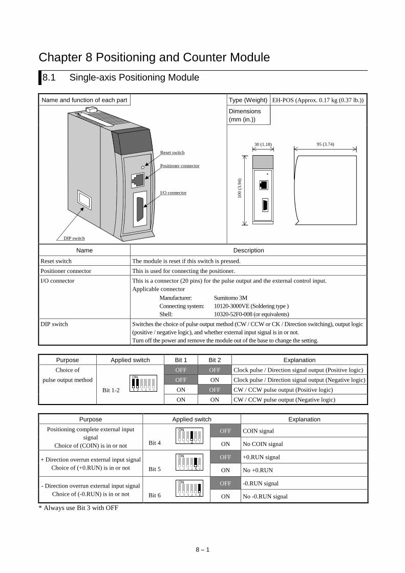
8 – 1
Chapter 8 Positioning and Counter Module
8.1 Single-axis Positioning Module
Name and function of each part Type (Weight) EH-POS (Approx. 0.17 kg (0.37 lb.))
Reset switch
Positioner connector
I/O connector
DIP switch
Dimensions
(mm (in.))
30 (1.18)
10
0 (
3.9
4)
95 (3.74)
Name Description
Reset switch The module is reset if this switch is pressed.
Positioner connector This is used for connecting the positioner.
I/O connector This is a connector (20 pins) for the pulse output and the external control input.
Applicable connector
Manufacturer: Sumitomo 3M
Connecting system: 10120-3000VE (Soldering type )
Shell: 10320-52F0-008 (or equivalents)
DIP switch Switches the choice of pulse output method (CW / CCW or CK / Direction switching), output logic
(positive / negative logic), and whether external input signal is in or not.
Turn off the power and remove the module out of the base to change the setting.
Purpose Applied switch Bit 1 Bit 2 Explanation
Choice of
Bit 1-2
ON
1 2 3 4 5 6
OFF OFF Clock pulse / Direction signal output (Positive logic)
pulse output method OFF ON Clock pulse / Direction signal output (Negative logic)
ON OFF CW / CCW pulse output (Positive logic)
ON ON CW / CCW pulse output (Negative logic)
Purpose Applied switch Explanation
Positioning complete external input
signal
Choice of (COIN) is in or not Bit 4
ON
1 2 3 4 5 6
OFF COIN signal
ON No COIN signal
+ Direction overrun external input signal
Choice of (+0.RUN) is in or not Bit 5
ON
1 2 3 4 5 6
OFF +0.RUN signal
ON No +0.RUN
- Direction overrun external input signal
Choice of (-0.RUN) is in or not Bit 6
ON
1 2 3 4 5 6
OFF -0.RUN signal
ON No -0.RUN signal
* Always use Bit 3 with OFF
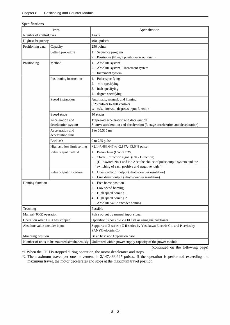
Chapter 8 Positioning and Counter Module
8 – 2
Specifications
Item Specification
Number of control axes 1 axis
Highest frequency 400 kpulse/s
Positioning data Capacity 256 points
Setting procedure 1. Sequence program
2. Positioner (Note, a positioner is optional.)
Positioning Method 1. Absolute system
2. Absolute system + Increment system
3. Increment system
Positioning instruction 1. Pulse specifying
2. μm specifying
3. inch specifying
4. degree specifying
Speed instruction Automatic, manual, and homing
6.25 pulse/s to 400 kpulse/s
μ m/s、inch/s、degree/s input function
Speed stage 10 stages
Acceleration and
deceleration system
Trapezoid acceleration and deceleration
S-curve acceleration and deceleration (3-stage acceleration and deceleration)
Acceleration and
deceleration time
1 to 65,535 ms
Backlash 0 to 255 pulse
High and low limit setting +2,147,483,647 to -2,147,483,648 pulse
Pulse output method 1. Pulse chain (CW / CCW)
2. Clock + direction signal (CK / Direction)
(DIP switch No.1 and No.2 set the choice of pulse output system and the
switching of each positive and negative logic.)
Pulse output procedure 1. Open collector output (Photo-coupler insulation)
2. Line driver output (Photo-coupler insulation)
Homing function 1. Free home position
2. Low speed homing
3. High speed homing 1
4. High speed homing 2
5. Absolute value encoder homing
Teaching Possible
Manual (JOG) operation Pulse output by manual input signal
Operation when CPU has stopped Operation is possible via I/O set or using the positioner
Absolute value encoder input Supports to series / II series by Yasukawa Electric Co. and P series by
SANYO electric Co.
Mounting position Basic base and Expansion base
Number of units to be mounted simultaneously Unlimited within power supply capacity of the power module
(continued on the following page)
*1 When the CPU is stopped during operation, the motor decelerates and stops.
*2 The maximum travel per one movement is 2,147,483,647 pulses. If the operation is performed exceeding the
maximum travel, the motor decelerates and stops at the maximum travel position.

Chapter 8 Positioning and Counter Module
8 – 3
Specifications (continued from the preceding page)
Item Specification
Output Pulse chain (CW / CCW) output
Clock + Direction signal
(CK / Direction) pulse output
1. Open collector output photo-coupler insulation
(30 V DC at the maximum, 30 mA resistive load)
2. Line driver output photo-coupler insulation (5 V DC)
Maximum leak current 100 A or less
Maximum voltage drop at ON 0.8 V at the maximum (at output current 30 mA)
Input Input voltage 10.8 to 30 V DC
Input impedance Approx. 2.2 kΩ
Input current Approx. 10 mA (24 V DC)
Operating
voltage
Minimum ON voltage 9 V
Maximum OFF voltage 3.6 V
Input lag ON OFF 1 ms or less
OFF ON 1 ms or less
Polarity Only encoder signal input uses the plus common inside the unit, and other inputs do
not specify polarity.
Insulation system Photo-coupler
A) Specifications of Positioner connector (CN1): conforms to RS-422
Terminal configuration No. Signal Signal name Diagram of Internal circuit
1
8
......
1 Do - Driver output -
8 7 6 5
2 1
4 3
Po
siti
oner
Internal
circuit -12 V GND
5 V
5 V
GND
2 Do + Driver output +
3 Ri - Receiver input -
4 Ri + Receiver input +
5 5 V DC + + 5 V
6 0 V GND
7 0 V GND
8 12 V DC - -12 V
B) Specifications of I/O connector (CN2)
Terminal configuration No. Signal Signal name Diagram of Internal circuit
11
20
1
10
. . . . . .
. . . . . .
1 5 V DC + Pulse output power
supply
Internal circuit
5 V
20
2
3, 4
1
5, 7
5 V
6, 8
9, 11
10, 12
13 to 19
2 0 V
3 CW Open collector pulse
output 4 CCW
5 CW +
Line driver pulse
output
6 CW -
7 CCW +
8 CCW -
9 C + Encoder C phase
10 C -
11 PS - Encoder position
signal 12 PS +
13 COIN Positioning complete
14 PROG Home position LS
15 + 0.RUN + Overrun
16 - 0.RUN - Overrun
17 MODE - SEL Control mode switch
18 M - CW Manual CW
19 M - CCW Manual CCW
20 24 V DC + Control power supply
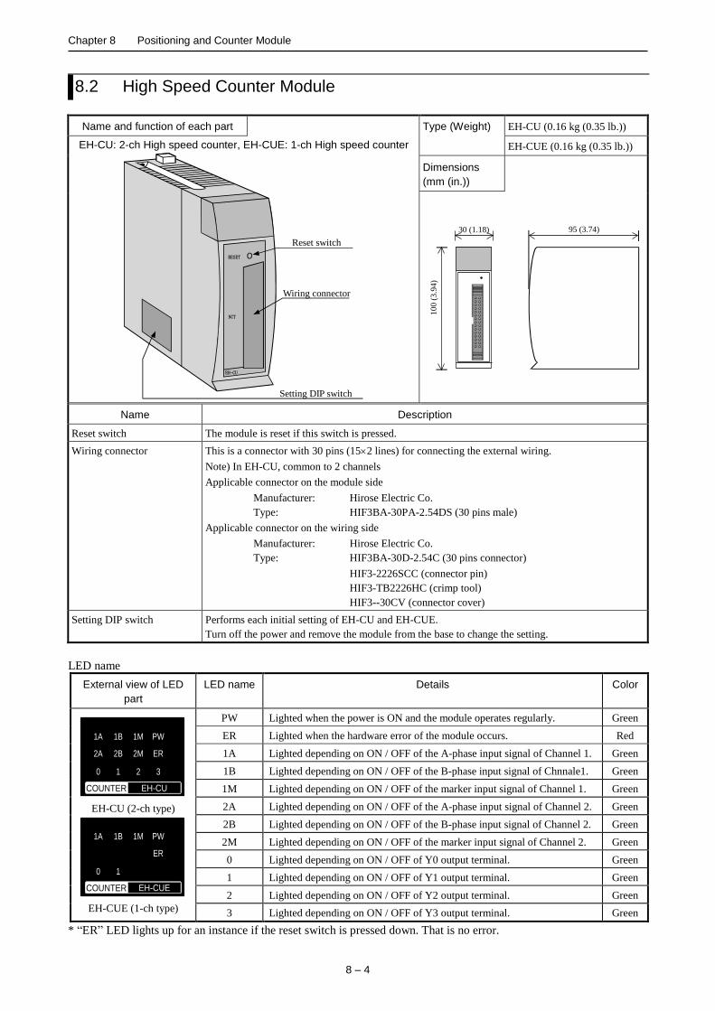
Chapter 8 Positioning and Counter Module
8 – 4
8.2 High Speed Counter Module
Name and function of each part Type (Weight) EH-CU (0.16 kg (0.35 lb.))
EH-CU: 2-ch High speed counter, EH-CUE: 1-ch High speed counter
RESET
NCT
EH-CU
Wiring connector
Reset switch
Setting DIP switch
EH-CUE (0.16 kg (0.35 lb.))
Dimensions
(mm (in.))
30 (1.18)
10
0 (
3.9
4)
95 (3.74)
Name Description
Reset switch The module is reset if this switch is pressed.
Wiring connector This is a connector with 30 pins (152 lines) for connecting the external wiring.
Note) In EH-CU, common to 2 channels
Applicable connector on the module side
Manufacturer: Hirose Electric Co.
Type: HIF3BA-30PA-2.54DS (30 pins male)
Applicable connector on the wiring side
Manufacturer: Hirose Electric Co.
Type: HIF3BA-30D-2.54C (30 pins connector)
HIF3-2226SCC (connector pin)
HIF3-TB2226HC (crimp tool)
HIF3--30CV (connector cover)
Setting DIP switch Performs each initial setting of EH-CU and EH-CUE.
Turn off the power and remove the module from the base to change the setting.
LED name
External view of LED
part
LED name Details Color
COUNTER EH-CU
1A
2A
0
1B
2B
1
1M
2M
2
PW
ER
3
EH-CU (2-ch type)
COUNTER EH-CUE
1A
0
1B
1
1M PW
ER
EH-CUE (1-ch type)
PW Lighted when the power is ON and the module operates regularly. Green
ER Lighted when the hardware error of the module occurs. Red
1A Lighted depending on ON / OFF of the A-phase input signal of Channel 1. Green
1B Lighted depending on ON / OFF of the B-phase input signal of Chnnale1. Green
1M Lighted depending on ON / OFF of the marker input signal of Channel 1. Green
2A Lighted depending on ON / OFF of the A-phase input signal of Channel 2. Green
2B Lighted depending on ON / OFF of the B-phase input signal of Channel 2. Green
2M Lighted depending on ON / OFF of the marker input signal of Channel 2. Green
0 Lighted depending on ON / OFF of Y0 output terminal. Green
1 Lighted depending on ON / OFF of Y1 output terminal. Green
2 Lighted depending on ON / OFF of Y2 output terminal. Green
3 Lighted depending on ON / OFF of Y3 output terminal. Green
* “ER” LED lights up for an instance if the reset switch is pressed down. That is no error.

Chapter 8 Positioning and Counter Module
8 – 5
Purpose Applied switch Bit1 Bit 2 Explanation
Select the counter mode
(Common between
channels)
Bit 1, 2
ON
1 2 3 4 5 6 7 8 9 10
OFF OFF 2-phase counter (100 kHz at the maximum)
OFF ON 1-phase counter (CW, CCW)
ON OFF 1-phase counter (CK, UP / DOWN)
ON ON 2-phase multiplied by 4 counter (25 kHz at the maximum)
Purpose Applied switch Explanation
Select the marker polarity
Bit 3
ON
1 2 3 4 5 6 7 8 9 10
OFF Channel 1 Detects the marker at the input OFF edge.
ON Channel 1 Detects the marker at the input ON edge.
Bit 4
ON
1 2 3 4 5 6 7 8 9 10
OFF Channel 2 Detects the marker at the input OFF edge.
ON Channel 2 Detects the marker at the input ON edge.
Select counting operation
during STOP Bit 5
ON
1 2 3 4 5 6 7 8 9 10
OFF Channel 1 Stops counting while the CPU module stops.
ON Channel 1 Keeps counting while the CPU module stops.
Bit 6
ON
1 2 3 4 5 6 7 8 9 10
OFF Channel 2 Stops counting while the CPU module stops.
ON Channel 2 Keeps counting while the CPU module stops.
Select normal counter /
ring counter Bit 7
ON
1 2 3 4 5 6 7 8 9 10
OFF Channel 1 Normal counter
ON Channel 1 Ring counter
Bit 8
ON
1 2 3 4 5 6 7 8 9 10
OFF Channel 2 Normal counter
ON Channel 2 Ring counter
Select the test mode
Bit 9
ON
1 2 3 4 5 6 7 8 9 10
OFF Normal operation
ON Test mode (Program for checking is started up.)
* Always use Bit 10 with OFF.

Chapter 8 Positioning and Counter Module
8 – 6
Specifications
Item Specification
Type EH-CU EH-CUE
Number of channels 2 channels 1 channel
Number of counts at the maximum 32 bits (0 to 4,294,967,295)
Maximum frequency 100 k Hz (25 k Hz at multiplied by 4)
Count mode Select by setting of DIP switch. (EH-CU is common to both channels.)
2-phase, 1-phase (CW / CCW, CK, U / D), 2-phase multiplied by 4
Differential input current 4 mA or more
Differential input voltage 12 to 24 V DC
Minimum ON voltage 10 V DC
Maximun OFF voltage 4 V DC
Insulation system Photo-coupler
Number of input
points
3 points / CH
A:A, CW, CK Phase difference of each channel (A - B) during 2-phase counting
+45 to +125 when up, -45 to -125 when down B:B, CCW, U / D
M: Marker (z)
Minimum counter pulse width ON: 4 s or more, OFF: 4 s or more
Minimum marker pulse width 10 s or more (detected at ON edge)
External wiring method 30-pin batch connector for both channels 30-pin connector
External wiring Wired with twisted pair cables and batch shielded cables
Output voltage 12 / 24 V DC (30 V DC at the maximum)
Load current 20 mA / point at the maximum
Output method Open collector output
Minimum load current 1 mA
Output delay time ON OFF 1 ms or less
OFF ON 1 ms or less
Voltage down at ON 1.5 V at the maximum
Number of external output points 4 points / module
External terminal of output destination
can be specified for each channel
2 points / module
Normal counter Current value = Set value 1, or Current value > Set value 1
Ring counter Current value = Set value 2
Leak current 0.5 mA at the maximum
Polarity (-) common within the module
External power supply 12 / 24 V DC (30 V DC at the maximum)
Insulation system Photo-coupler
Mounting position Basic base, Expansion base (cannot mount on the remote base)
Number of units to be mounted
simultaneously
Unlimited within power supply capacity of the power module.

Chapter 8 Positioning and Counter Module
8 – 7
Specifications of I/O terminal
EH-CU Terminal
configuration No. CH2 No. CH1 Meaning of signal
RESET
EH-CU
CH2 CH1
16 1
30 15
CN1
16 Vin A 1 Vin A
Phase A
Connects to a 12 to 24 V DC power supply at using voltage input.
17 A (+) 2 A (+) Connects (+) polarity at using differential input.
18 A (-) 3 A (-)
Connects an open collector signal at using voltage input. Connects (-) polarity at using differential input.
19 Vin B 4 Vin B
Phase B
Connects to a 12 to 24 V DC power supply at using voltage input.
20 B (+) 5 B (+) Connects (+) polarity at using differential input.
21 B (-) 6 B (-)
Connects an open collector signal at using voltage input. Connects (-) polarity at using differential input.
22 Vin M 7 Vin M
Marker
Connects to a 12 to 24 V DC power supply at using voltage input.
23 M (+) 8 M (+) Connects (+) polarity at using differential input.
24 M (-) 9 M (-)
Connects an open collector signal at using voltage input.
Connects (-) polarity at using differential input.
25 to 27 N.C. 10 to 12 N.C. Connect nothing.
28 Y2 13 Y0
Output
Coincidence output. Connects to the other input.
29 Y3 14 Y1 Coincidence output. Connects to the other input.
30 Com2 15 Com1 (-) common for coincidence common.
Commons 1 and 2 are independent.
* Pin No. defined in EH-CU does not accord with pin No. defined by connector maker.
EH-CUE Terminal
configuration No. CH2 No. CH1 Meaning of signal
RESET
EH-CUE
CH2 CH1
16 1
30 15
CN1
16 N.C. 1 Vin A
Phase A
Connects to a 12 to 24 V DC power supply at using voltage input.
17 N.C. 2 A (+) Connects (+) polarity at using differential input.
18 N.C. 3 A (-)
Connects an open collector signal at using voltage input. Connects (-) polarity at using differential input.
19 N.C. 4 Vin B
Phase B
Connects to a 12 to 24 V DC power supply at using voltage input.
20 N.C. 5 B (+) Connects (+) polarity at using differential input.
21 N.C. 6 B (-)
Connects an open collector signal at using voltage input. Connects (-) polarity at using differential input.
22 N.C. 7 Vin M
Marker
Connects to a 12 to 24 V DC power supply at using voltage input.
23 N.C. 8 M (+) Connects (+) polarity at using differential input.
24 N.C. 9 M (-)
Connects an open collector signal at using voltage input. Connects (-) polarity at using differential input.
25 to 27 N.C. 10 to 12 N.C. Connect nothing.
28 N.C. 13 Y0
Output
Coincidence output. Connects to the other input.
29 N.C. 14 Y1 Coincidence output. Connects to the other input.
30 N.C. 15 Com1 (-) common for coincidence output.
* Pin No. defined in EH-CUE does not accord with pin No. defined by the connector maker.

Chapter 8 Positioning and Counter Module
8 – 8
MEMO
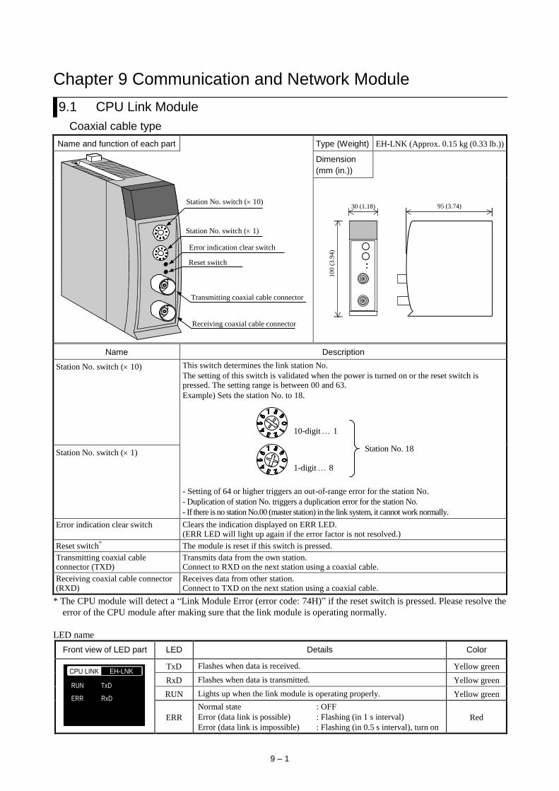
9 – 1
Chapter 9 Communication and Network Module
9.1 CPU Link Module
Coaxial cable type
Name and function of each part Type (Weight) EH-LNK (Approx. 0.15 kg (0.33 lb.))
Transmitting coaxial cable connector
Receiving coaxial cable connector
Error indication clear switch
Station No. switch ( 1)
Station No. switch ( 10)
Reset switch
Dimension
(mm (in.))
30 (1.18)
10
0 (
3.9
4)
95 (3.74)
Name Description
Station No. switch ( 10)
This switch determines the link station No.
The setting of this switch is validated when the power is turned on or the reset switch is pressed. The setting range is between 00 and 63.
Example) Sets the station No. to 18.
Station No. 18
10-digit 1
1-digit 8
- Setting of 64 or higher triggers an out-of-range error for the station No.
- Duplication of station No. triggers a duplication error for the station No.
- If there is no station No.00 (master station) in the link system, it cannot work normally.
Station No. switch ( 1)
Error indication clear switch Clears the indication displayed on ERR LED. (ERR LED will light up again if the error factor is not resolved.)
Reset switch* The module is reset if this switch is pressed.
Transmitting coaxial cable connector (TXD)
Transmits data from the own station. Connect to RXD on the next station using a coaxial cable.
Receiving coaxial cable connector (RXD)
Receives data from other station. Connect to TXD on the next station using a coaxial cable.
* The CPU module will detect a “Link Module Error (error code: 74H)” if the reset switch is pressed. Please resolve the
error of the CPU module after making sure that the link module is operating normally.
LED name
Front view of LED part LED Details Color
CPU LINK EH-LNK
RUN
ERR
TxD
RxD
TxD Flashes when data is received. Yellow green
RxD Flashes when data is transmitted. Yellow green
RUN Lights up when the link module is operating properly. Yellow green
ERR
Normal state : OFF
Error (data link is possible) : Flashing (in 1 s interval)
Error (data link is impossible) : Flashing (in 0.5 s interval), turn on
Red
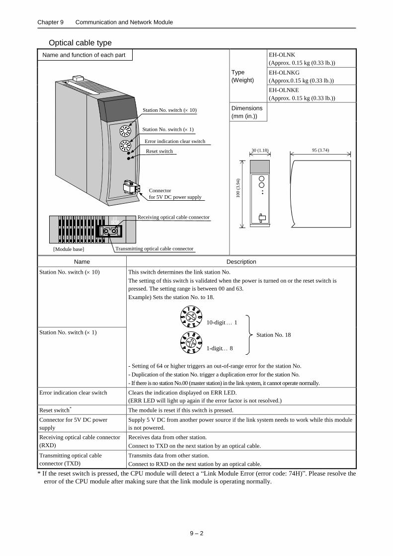
Chapter 9 Communication and Network Module
9 – 2
Optical cable type
RX
D
TX
D
Error indication clear switch
Station No. switch ( 1)
Station No. switch ( 10)
Connector
for 5V DC power supply
Transmitting optical cable connector
Reset switch
[Module base]
Receiving optical cable connector
Type
(Weight)
EH-OLNK
(Approx. 0.15 kg (0.33 lb.))
EH-OLNKG
(Approx.0.15 kg (0.33 lb.))
EH-OLNKE
(Approx. 0.15 kg (0.33 lb.))
Dimensions
(mm (in.))
30 (1.18)
10
0 (
3.9
4)
95 (3.74)
Name Description
Station No. switch ( 10) This switch determines the link station No.
The setting of this switch is validated when the power is turned on or the reset switch is
pressed. The setting range is between 00 and 63.
Example) Sets the station No. to 18.
Station No. 18
10-digit 1
1-digit 8
- Setting of 64 or higher triggers an out-of-range error for the station No.
- Duplication of the station No. trigger a duplication error for the station No.
- If there is no station No.00 (master station) in the link system, it cannot operate normally.
Station No. switch ( 1)
Error indication clear switch Clears the indication displayed on ERR LED.
(ERR LED will light up again if the error factor is not resolved.)
Reset switch* The module is reset if this switch is pressed.
Connector for 5V DC power
supply
Supply 5 V DC from another power source if the link system needs to work while this module
is not powered.
Receiving optical cable connector
(RXD)
Receives data from other station.
Connect to TXD on the next station by an optical cable.
Transmitting optical cable
connector (TXD)
Transmits data from other station.
Connect to RXD on the next station by an optical cable.
* If the reset switch is pressed, the CPU module will detect a “Link Module Error (error code: 74H)”. Please resolve the
error of the CPU module after making sure that the link module is operating normally.
Name and function of each part
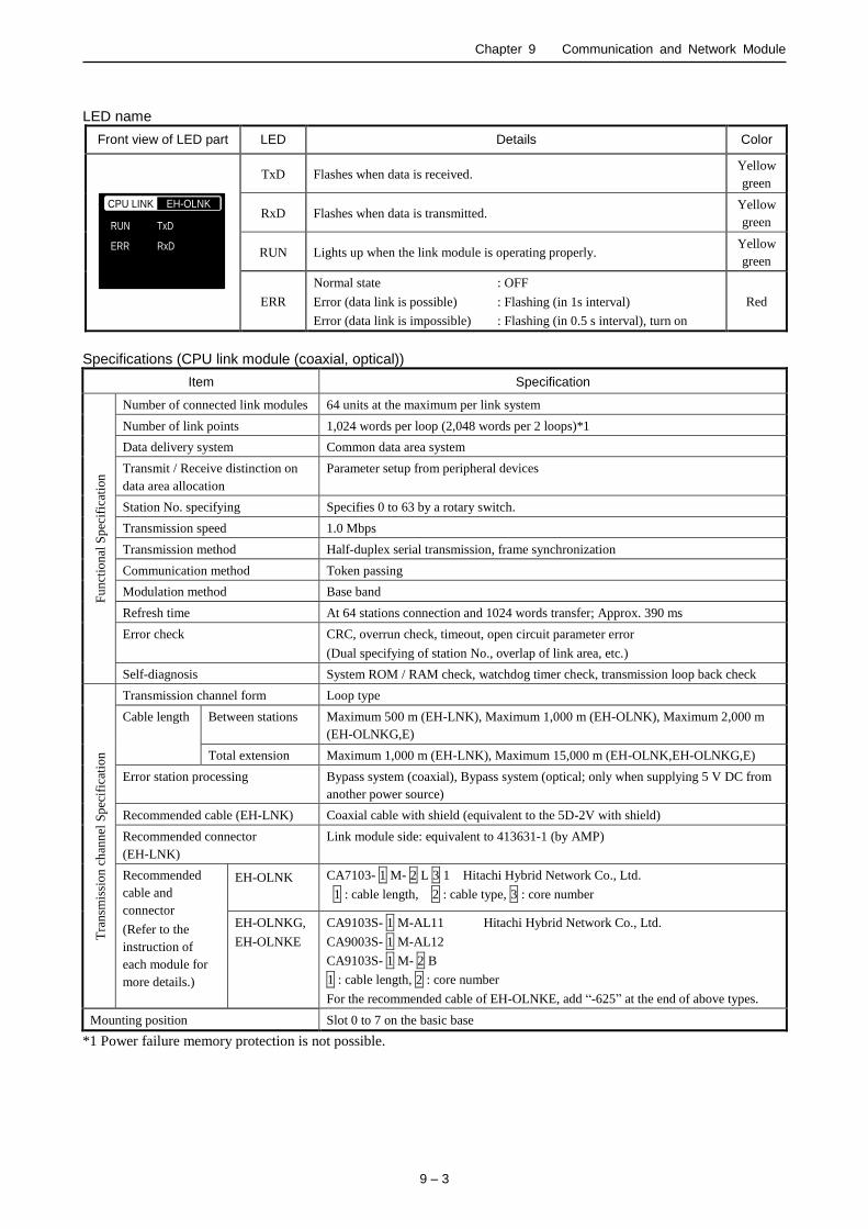
Chapter 9 Communication and Network Module
9 – 3
LED name
Front view of LED part LED Details Color
CPU LINK EH-OLNK
RUN
ERR
TxD
RxD
TxD Flashes when data is received. Yellow
green
RxD Flashes when data is transmitted. Yellow
green
RUN Lights up when the link module is operating properly. Yellow
green
ERR
Normal state : OFF
Error (data link is possible) : Flashing (in 1s interval)
Error (data link is impossible) : Flashing (in 0.5 s interval), turn on
Red
Specifications (CPU link module (coaxial, optical))
Item Specification
Fu
nct
ion
al S
pec
ific
atio
n
Number of connected link modules 64 units at the maximum per link system
Number of link points 1,024 words per loop (2,048 words per 2 loops)*1
Data delivery system Common data area system
Transmit / Receive distinction on
data area allocation
Parameter setup from peripheral devices
Station No. specifying Specifies 0 to 63 by a rotary switch.
Transmission speed 1.0 Mbps
Transmission method Half-duplex serial transmission, frame synchronization
Communication method Token passing
Modulation method Base band
Refresh time At 64 stations connection and 1024 words transfer; Approx. 390 ms
Error check CRC, overrun check, timeout, open circuit parameter error
(Dual specifying of station No., overlap of link area, etc.)
Self-diagnosis System ROM / RAM check, watchdog timer check, transmission loop back check
Tra
nsm
issi
on
ch
ann
el S
pec
ific
atio
n
Transmission channel form Loop type
Cable length Between stations Maximum 500 m (EH-LNK), Maximum 1,000 m (EH-OLNK), Maximum 2,000 m
(EH-OLNKG,E)
Total extension Maximum 1,000 m (EH-LNK), Maximum 15,000 m (EH-OLNK,EH-OLNKG,E)
Error station processing Bypass system (coaxial), Bypass system (optical; only when supplying 5 V DC from
another power source)
Recommended cable (EH-LNK) Coaxial cable with shield (equivalent to the 5D-2V with shield)
Recommended connector
(EH-LNK)
Link module side: equivalent to 413631-1 (by AMP)
Recommended
cable and
connector
(Refer to the
instruction of
each module for
more details.)
EH-OLNK
CA7103- 1 M- 2 L 3 1 Hitachi Hybrid Network Co., Ltd.
1 : cable length, 2 : cable type, 3 : core number
EH-OLNKG,
EH-OLNKE
CA9103S- 1 M-AL11 Hitachi Hybrid Network Co., Ltd.
CA9003S- 1 M-AL12
CA9103S- 1 M- 2 B
1 : cable length, 2 : core number
For the recommended cable of EH-OLNKE, add “-625” at the end of above types.
Mounting position Slot 0 to 7 on the basic base
*1 Power failure memory protection is not possible.
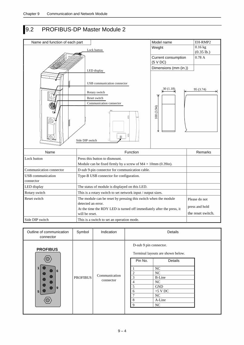
Chapter 9 Communication and Network Module
9 – 4
9.2 PROFIBUS-DP Master Module 2
Name and function of each part Model name EH-RMP2
USB communication connector
Communication connector
LED display
Reset switch
Lock button
Side DIP switch
Rotary switch
Weight 0.16 kg
(0.35 lb.)
Current consumption
(5 V DC)
0.78 A
Dimensions (mm (in.))
30 (1.18)
100
(3.9
4)
95 (3.74)
Name Function Remarks
Lock button Press this button to dismount.
Module can be fixed firmly by a screw of M4 × 10mm (0.39in).
Communication connector D-sub 9-pin connector for communication cable.
USB communication
connector
Type-B USB connector for configuration.
LED display The status of module is displayed on this LED.
Rotary switch This is a rotary switch to set network input / output sizes.
Reset switch The module can be reset by pressing this switch when the module
detected an error.
At the time the RDY LED is turned off immediately after the press, it
will be reset.
Please do not
press and hold
the reset switch.
Side DIP switch This is a switch to set an operation mode.
Outline of communication
connector
Symbol Indication Details
PROFIBUS
1
5
6
9
PROFIBUS Communication
connector
D-sub 9 pin connector.
Terminal layouts are shown below.
Pin No. Details
1 NC
2 NC
3 B-Line
4 NC
5 GND
6 +5 V DC
7 NC
8 A-Line
9 NC

Chapter 9 Communication and Network Module
9 – 5
Description of LED display
LED LED
name Indication Details
RDY
STATUS
RUN ERR
REM
PROFIBUS EH-RMP2
RDY Hardware status
(Green / Red)
Display EH-RMP2 hardware status.
State Details
Off Hardware error
Power supply error
Flash in green or red Initialization
Lit in red Hardware error
Lit in green No error
STATUS System status
(Green / Red)
Display EH-RMP2 system status.
State Details
Off Power supply error
Flash in red Internal error
Lit in red WDT error
Fifth-flash in green Side DIP switch setting error
Forth-flash in green Link parameter error
Triple-flash in green Configuration data error
Double-flash in green CPU module error
Single-flash in green Initialization
Lit in green No error
RUN Network status
(Green)
Display PROFIBUS network status.
State Details
Off No communication established
Blinking Under communication establishment
On Communication established
ERR Error status
(Red)
Display PROFIBUS error status.
State Details
Off Communication established
Blinking Slave units at least one are not
established
On All slave units are not established
REM Operating mode
(Green) No use. It is always off.
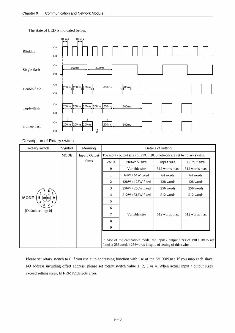
Chapter 9 Communication and Network Module
9 – 6
The state of LED is indicated below.
Triple-flash
Single-flash
Double-flash
On
Off
On
Off
On
Off
200ms 200ms
500ms
200ms 200ms 200ms 200ms 600ms
200ms 200ms 200ms 600ms
Blinking
On
Off
100ms
n times-flash
On
Off
200ms 200ms 200ms 200ms
1 2 n
100ms
500ms
600ms
Description of Rotary switch
Rotary switch Symbol Meaning Details of setting
MODE 4
0
8
1 2 3
9
5
6 7
[Default setting: 0]
MODE Input / Output
Sizes
The input / output sizes of PROFIBUS network are set by rotary switch.
Value Network size Input size Output size
0 Variable size 512 words max 512 words max
1 64W / 64W fixed 64 words 64 words
2 128W / 128W fixed 128 words 128 words
3 256W / 256W fixed 256 words 256 words
4 512W / 512W fixed 512 words 512 words
5
Variable size 512 words max 512 words max
6
7
8
9
In case of the compatible mode, the input / output sizes of PROFIBUS are
fixed at 256words / 256words in spite of setting of this switch.
Please set rotary switch to 0 if you use auto addressing function with use of the SYCON.net. If you map each slave
I/O address including offset address, please set rotary switch value 1, 2, 3 or 4. When actual input / output sizes
exceed setting sizes, EH-RMP2 detects error.
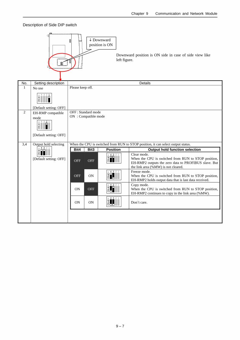
Chapter 9 Communication and Network Module
9 – 7
Description of Side DIP switch
No. Setting description Details
1 No use
1
ON
2
3
4
[Default setting: OFF]
Please keep off.
2 EH-RMP compatible
mode
ON
2
3
4
1
[Default setting: OFF]
OFF : Standard mode
ON : Compatible mode
3,4 Output hold selecting
ON
2
3
4
1
[Default setting: OFF]
When the CPU is switched from RUN to STOP position, it can select output status.
Bit4 Bit3 Position Output hold function selection
OFF OFF
3
4
1
ON
2
Clear mode.
When the CPU is switched from RUN to STOP position,
EH-RMP2 outputs the zero data to PROFIBUS slave. But
the link area (%MW) is not cleared.
OFF ON 3
4
1
ON
2
Freeze mode.
When the CPU is switched from RUN to STOP position,
EH-RMP2 holds output data that is last data received.
ON OFF 3
4
1
ON
2
Copy mode.
When the CPU is switched from RUN to STOP position,
EH-RMP2 continues to copy in the link area (%MW).
ON ON 3
4
1
ON
2
Don’t care.
Downward position is ON side in case of side view like
left figure.
Downward
position is ON

Chapter 9 Communication and Network Module
9 – 8
Performance specification
Item
Specifications
EH-RMP2 EH-RMP
(Existing model) Standard mode Compatible mode
Co
mm
un
icat
ion
sp
ecif
icat
ion
s
Communication protocol PROFIBUS-DP V0
Range of node address 0 to 125: Setting by configuration tool
Maximum I/O size Input: 512 words, output: 512 words
(Setting by rotary switch)
Input: 256 words, output: 256 words
Connector D-sub 9 pin
Topology BUS
Communication cable PROFIBUS cable
Segment length,
Transmit speed
9.6
19.2
93.75
187.5
500
1,500
3
6
12
kbps
kbps
kbps
kbps
kbps
kbps
Mbps
Mbps
Mbps
: 1,200 m
: 1,200 m
: 1,200 m
: 1,000 m
: 400 m
: 200 m
: 100 m
: 100 m
: 100 m
Maximum connectable
number of slaves 125 slaves
Output hold Supported (Clear mode, Freeze mode, Copy mode)
Termination Not built-in Built-in
Configuration tool SYCON.net SyCon
Func
tiona
l spe
cific
atio
ns
ons
Number of modules 8 modules / CPU
Self-check WDT check
WDT check
System memory check
Error indication LED
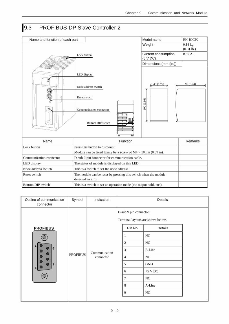
Chapter 9 Communication and Network Module
9 – 9
9.3 PROFIBUS-DP Slave Controller 2
Name and function of each part Model name EH-IOCP2
Node address switch
Communication connector
LED display
Reset switch
Lock button
Bottom DIP switch
Weight 0.14 kg
(0.31 lb.)
Current consumption
(5 V DC)
0.35 A
Dimensions (mm (in.))
45 (1.77) 95 (3.74)
10
0 (
3.9
4)
Name Function Remarks
Lock button Press this button to dismount.
Module can be fixed firmly by a screw of M4 × 10mm (0.39 in).
Communication connector D-sub 9-pin connector for communication cable.
LED display The status of module is displayed on this LED.
Node address switch This is a switch to set the node address.
Reset switch The module can be reset by pressing this switch when the module
detected an error.
Bottom DIP switch This is a switch to set an operation mode (the output hold, etc.).
Outline of communication
connector
Symbol Indication Details
PROFIBUS
1
5
6
9
PROFIBUS Communication
connector
D-sub 9 pin connector.
Terminal layouts are shown below.
Pin No. Details
1 NC
2 NC
3 B-Line
4 NC
5 GND
6 +5 V DC
7 NC
8 A-Line
9 NC
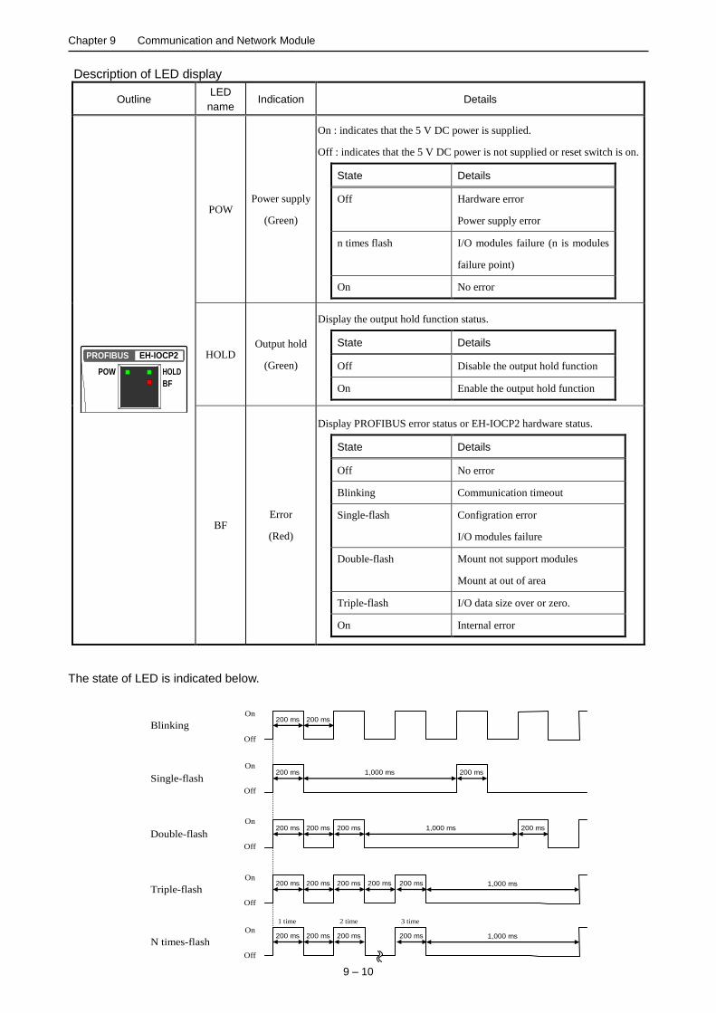
Chapter 9 Communication and Network Module
9 – 10
Description of LED display
The state of LED is indicated below.
Outline LED
name Indication Details
HOLD
BF
POW
PROFIBUS EH-IOCP2
POW Power supply
(Green)
On : indicates that the 5 V DC power is supplied.
Off : indicates that the 5 V DC power is not supplied or reset switch is on.
State Details
Off Hardware error
Power supply error
n times flash I/O modules failure (n is modules
failure point)
On No error
HOLD Output hold
(Green)
Display the output hold function status.
State Details
Off Disable the output hold function
On Enable the output hold function
BF Error
(Red)
Display PROFIBUS error status or EH-IOCP2 hardware status.
State Details
Off No error
Blinking Communication timeout
Single-flash Configration error
I/O modules failure
Double-flash Mount not support modules
Mount at out of area
Triple-flash I/O data size over or zero.
On Internal error
Triple-flash
Single-flash
Double-flash
On
Off
On
Off
On
Off
200 ms 200 ms
200 ms 200 ms
200 ms 200 ms 200 ms 200 ms
1,000 ms
1,000 ms
200 ms 200 ms 200 ms 1,000 ms
Blinking
On
Off
200 ms 200 ms
N times-flash
On
Off
200 ms 200 ms 200 ms 200 ms 1,000 ms
1 time 2 time 3 time

Chapter 9 Communication and Network Module
9 – 11
Description of Rotary switch
Rotary switch Symbol Meaning Details of setting
ADR
×10
4
0
8
1 2 3
9
5
6 7
×1
4
0
8
1 2 3
9
5
6 7
[Default setting : 00]
×10
(Tens place)
Station No.
(00 to 99)
The station No. of PROFIBUS network is set from 00 to 99.
The tens place set by upper rotary switch. The ones place set by
lower rotary switch.
×1
(Ones place)
Description of Bottom DIP switch
8
3
4
5
6
7
2
1
ON
No. Setting description Details
1 Output hold function
selecting
3
4
2
ON
1
[Default setting: OFF]
When the PROFIBUS master’s communication stopped, it is selected whether the output data
from the master is held or not. (Hold means the last data received properly is fixed.)
Output hold function may be changed action depending on master unit. Please read master’s
manual and check the combination master unit and EH-IOCP2, before using output hold function
of EH-IOCP2.
Bit1 Position Output hold function selection
OFF
3
4
2
ON
1
Disable the output hold function (Turn off all output data
from the master at the communication stopped.)
ON
3
4
2
ON
1
Enable the output hold function (At the communication
stopped, output data from master is held with last data
received properly.)
2 EH-IOCP compatible mode
selecting
3
4
1
ON
2
[Default setting: OFF]
It can select whether the EH-IOCP2 operates as standard mode or compatible mode.
Bit2 Position EH-IOCP compatible mode selection
OFF
3
4
1
ON
2
Standard mode (EH-IOCP2)
ON
3
4
1
ON
2
Compatible mode (EH-IOCP)
3 Data swap function
selecting
2
4
1
ON
3
[Default setting: OFF]
It can select whether it performs byte swap by a word unit.
Bit3 Position Data swap function selection
OFF
2
4
1
ON
3
Disable the data swap function
ON
2
4
1
ON
3
Enable the data swap function
4 No use
3
2
1
ON
4
[Default setting: OFF]
Please keep off.
Downward position is ON side in case of bottom view
like left figure.
Downward
position is ON
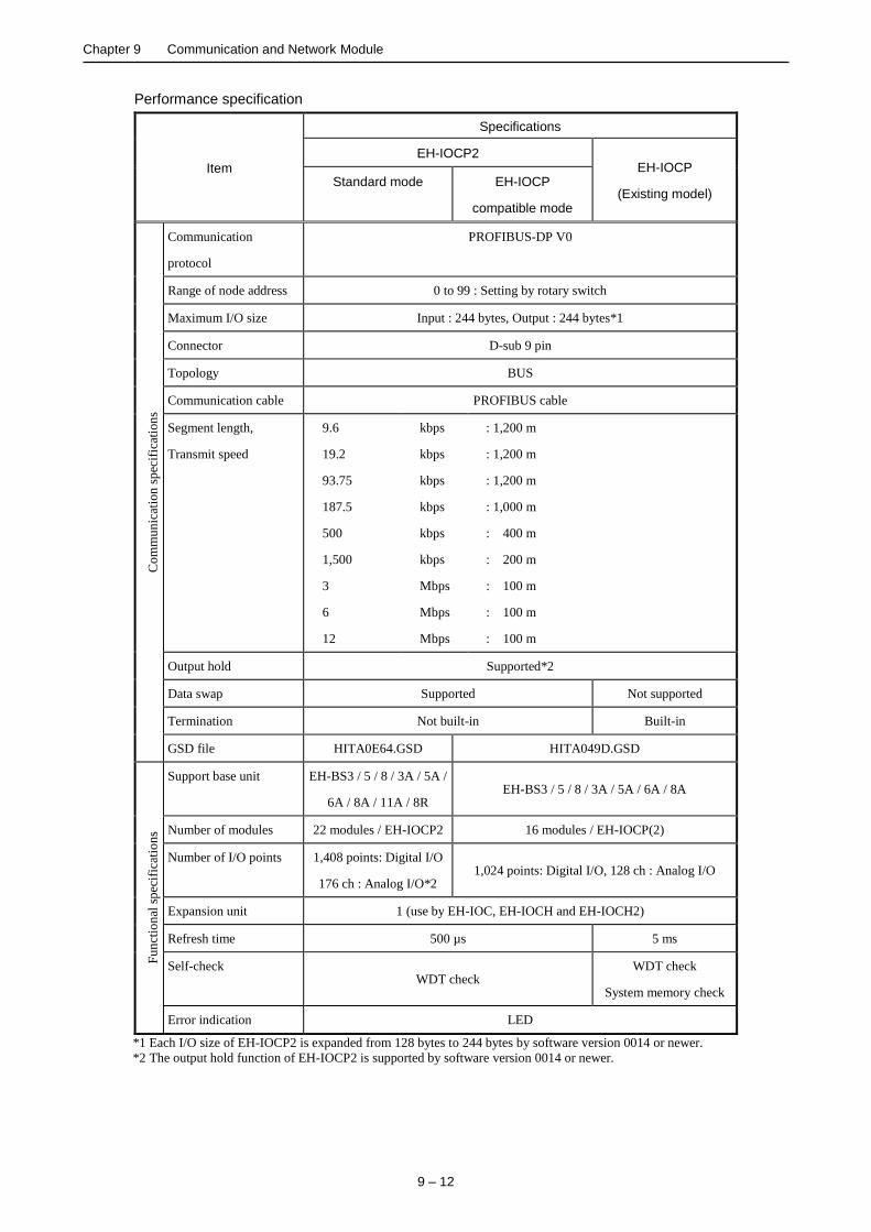
Chapter 9 Communication and Network Module
9 – 12
Performance specification
Item
Specifications
EH-IOCP2 EH-IOCP
(Existing model) Standard mode EH-IOCP
compatible mode
Co
mm
un
icat
ion
sp
ecif
icat
ion
s
Communication
protocol
PROFIBUS-DP V0
Range of node address 0 to 99 : Setting by rotary switch
Maximum I/O size Input : 244 bytes, Output : 244 bytes*1
Connector D-sub 9 pin
Topology BUS
Communication cable PROFIBUS cable
Segment length,
Transmit speed
9.6
19.2
93.75
187.5
500
1,500
3
6
12
kbps
kbps
kbps
kbps
kbps
kbps
Mbps
Mbps
Mbps
: 1,200 m
: 1,200 m
: 1,200 m
: 1,000 m
: 400 m
: 200 m
: 100 m
: 100 m
: 100 m
Output hold Supported*2
Data swap Supported Not supported
Termination Not built-in Built-in
GSD file HITA0E64.GSD HITA049D.GSD
Fu
nct
ion
al s
pec
ific
atio
ns
Support base unit EH-BS3 / 5 / 8 / 3A / 5A /
6A / 8A / 11A / 8R EH-BS3 / 5 / 8 / 3A / 5A / 6A / 8A
Number of modules 22 modules / EH-IOCP2 16 modules / EH-IOCP(2)
Number of I/O points 1,408 points: Digital I/O
176 ch : Analog I/O*2 1,024 points: Digital I/O, 128 ch : Analog I/O
Expansion unit 1 (use by EH-IOC, EH-IOCH and EH-IOCH2)
Refresh time 500 µs 5 ms
Self-check WDT check
WDT check
System memory check
Error indication LED
*1 Each I/O size of EH-IOCP2 is expanded from 128 bytes to 244 bytes by software version 0014 or newer.
*2 The output hold function of EH-IOCP2 is supported by software version 0014 or newer.

Chapter 9 Communication and Network Module
9 – 13
9.4 EtherCAT Slave Controller
Name and function of each part Model name EH-IOCA
LED display
Reset switch
Communication connector
(IN)
Lock button
Communication connector
(OUT)
Node address switch
Weight 0.14 kg
(0.31 lb.)
Dimensions (mm (in.))
45 (1.77) 95 (3.74)
10
0 (
3.9
4)
Name Function
Lock button Press this button to dismount.
Module can be fixed firmly by a screw of M4 × 10 mm (0.39 in).
LED display The status of module is displayed on this LED.
Node address switch This is a switch to set the node address.
Reset switch The module can be reset by pressing this switch when error such as the module abnormal
occurred.
Communication connector
(IN)
This is a connector to connect a cable for communication.
Communication connector
(OUT)
This is a connector to connect a cable for communication.
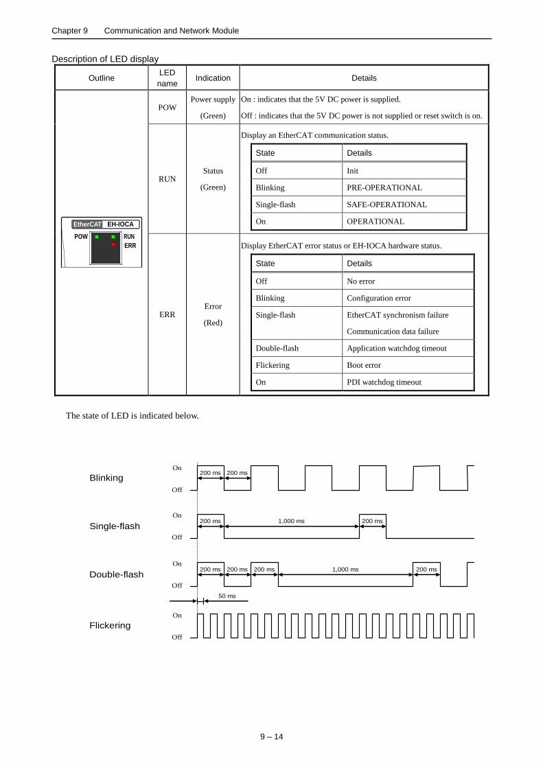
Chapter 9 Communication and Network Module
9 – 14
Description of LED display
The state of LED is indicated below.
Outline LED
name Indication Details
RUN
ERR
POW
EtherCAT EH-IOCA
POW Power supply
(Green)
On : indicates that the 5V DC power is supplied.
Off : indicates that the 5V DC power is not supplied or reset switch is on.
RUN Status
(Green)
Display an EtherCAT communication status.
State Details
Off Init
Blinking PRE-OPERATIONAL
Single-flash SAFE-OPERATIONAL
On OPERATIONAL
ERR Error
(Red)
Display EtherCAT error status or EH-IOCA hardware status.
State Details
Off No error
Blinking Configuration error
Single-flash EtherCAT synchronism failure
Communication data failure
Double-flash Application watchdog timeout
Flickering Boot error
On PDI watchdog timeout
Flickering
Blinking
Single-flash
Double-flash
On
Off
On
Off
On
Off
On
Off
50 ms
200 ms 200 ms
200 ms 200 ms
200 ms 200 ms 200 ms 200 ms
1,000 ms
1,000 ms

Chapter 9 Communication and Network Module
9 – 15
Description of Rotary switch
Rotary switch Symbol Meaning Details of setting
ADR
×10
4
0
8
1 2 3
9
5
6 7
×1
4
0
8
1 2 3
9
5
6 7
[Default setting : 00]
×10
(Tens place)
Station No.
(1 to 99)
The station No. of EtherCAT network is set from 1 to 99.
The tens place set by upper rotary switch. The ones place set by
lower rotary switch.
×1
(Ones place)
Node address of EH-IOCA is set by node address method of EtherCAT master unit. If EtherCAT master use fixed
node address method, rotary switch of EH-IOCA is valid. If EtherCAT master use logic node address method or
auto increment address method, rotary switch of EH-IOCA is invalid. If EtherCAT master use logic nodes address
method or auto increment address method, please set the rotary switch to “00”.
Description of Connector
Connector Symbol Indication Details
IN 8
1
8
1
LINK
ACT
LINK
ACT
OUT
IN Communication
connector RJ45 8-pin connector.
Terminal layouts are shown below.
Pin No. Details
1 Send data + (TD+)
2 Send data - (TD-)
3 Receive data + (RD+)
4 NC
5 NC
6 Receive data - (RD-)
7 NC
8 NC
OUT
LINK LINK LED
(Green)
LINK LED light up if the communication device are connected
with a cable.
ACT ACT LED
(Orange)
ACT LED is flashing during operation.
Recommended cable
Recommended cable of EH-IOCA is shown below. But if EH-IOCA is used in noisy environment, we recommend
cables with double, aluminum tape and braided shielding.
Item Details
Twisted pair cable 100BASE-TX (CAT 5 or higher)
STP cable
RJ45 connector CAT 5 or higher, Shielded
The maximum cable length between connected nodes is 100 m. Note that some cables do not guarantee 100 m. In
general, if the conductors are strand wire, the transmission performance will be lower than solid wire and the
operation at 100 m distance cannot be guaranteed. Confirm details with the cable manufacturer.
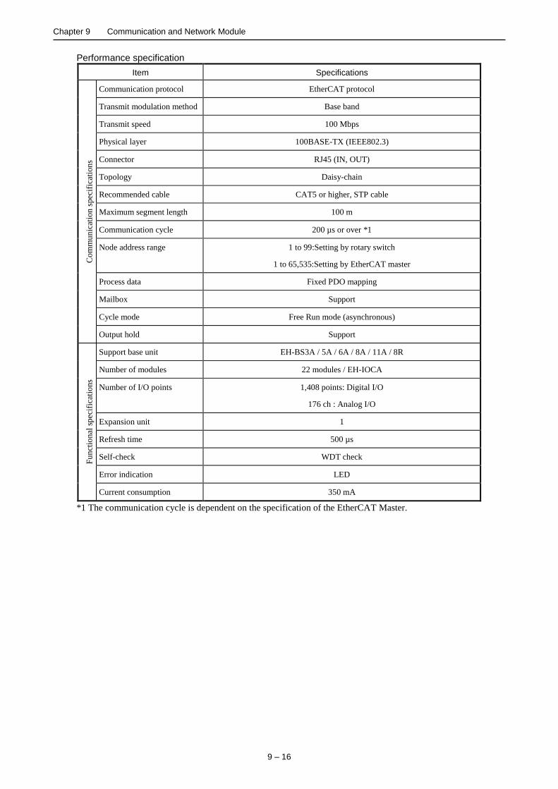
Chapter 9 Communication and Network Module
9 – 16
Performance specification
Item Specifications
Co
mm
un
icat
ion
sp
ecif
icat
ion
s Communication protocol EtherCAT protocol
Transmit modulation method Base band
Transmit speed 100 Mbps
Physical layer 100BASE-TX (IEEE802.3)
Connector RJ45 (IN, OUT)
Topology Daisy-chain
Recommended cable CAT5 or higher, STP cable
Maximum segment length 100 m
Communication cycle 200 µs or over *1
Node address range 1 to 99:Setting by rotary switch
1 to 65,535:Setting by EtherCAT master
Process data Fixed PDO mapping
Mailbox Support
Cycle mode Free Run mode (asynchronous)
Output hold Support
Fu
nct
ion
al s
pec
ific
atio
ns
Support base unit EH-BS3A / 5A / 6A / 8A / 11A / 8R
Number of modules 22 modules / EH-IOCA
Number of I/O points 1,408 points: Digital I/O
176 ch : Analog I/O
Expansion unit 1
Refresh time 500 µs
Self-check WDT check
Error indication LED
Current consumption 350 mA
*1 The communication cycle is dependent on the specification of the EtherCAT Master.

Chapter 9 Communication and Network Module
9 – 17
9.5 FL-net Module 3
Name and function of each part Model name EH-FLN3
LED display
Communication connector
Lock button
Reset switch
Weight 0.12 kg
(0.26 lb.)
Dimensions (mm (in.))
30 (1.18)
100
(3.9
4)
95 (3.74)
Name Function Remarks
Lock button Press this button to dismount.
Module can be fixed firmly by a screw of M4 × 10mm (0.39 in).
Communication connector RJ45 type connector.
LINK / ACT LED is turned on green at the time of cable connection and blinking
during communicating.
100M LED is turned on orange at 100 Mbps, and is turned off at 10 Mbps.
LED display The status of module is displayed on this LED.
Reset switch The module can be reset by pressing this switch when the module detected an error.
LINK / ACT
100M

Chapter 9 Communication and Network Module
9 – 18
Description of LED display
LED LED
name Indication Details
POW
LNK
TxD
FL-net
RxD
EH-FLN3
PER
HER
POW Power supply
(Green)
Display the power(5 V DC) status.
State Details
Off Power off
Lit in green Power on
LNK Network status
(Green)
Display the entry state of FL-net network.
State Details
Off Not participation in network
Lit in green Participation in network
TxD Transmit
(Green)
Display transmission status.
State Details
Off Not sending data
Lit in green Sending data
RxD Receive
(Green)
Display receiving status.
State Details
Off Not receiving data
Lit in green Receiving data
PER Parameter error
(Red)
Display parameter status.
State Details
Off No error
Lit in red Parameter error
HER Hardware error
(Red)
Display hardware status.
State Details
Off No error
Lit in red Hardware error

Chapter 9 Communication and Network Module
9 – 19
Description of Side DIP switch
No. Setting description Details
1 Communication mode
selecting
ON
2
3
4
1
[Default setting: OFF]
Sets up the communication speed.
Bit1 Position Communication mode
OFF 3
4
1
ON
2
10M / 100 Mbps Auto negotiation
ON 3
4
1
ON
2
10 Mbps fixed
2 No use
ON
2
3
4
1
[Default setting: OFF]
Please keep off.
3 No use
ON
2
3
4
1
[Default setting: OFF]
Please keep off.
4 No use
ON
2
3
4
1
[Default setting: OFF]
Please keep off.
Downward position is ON side in case of side
view like left figure.
Downward
Position is ON
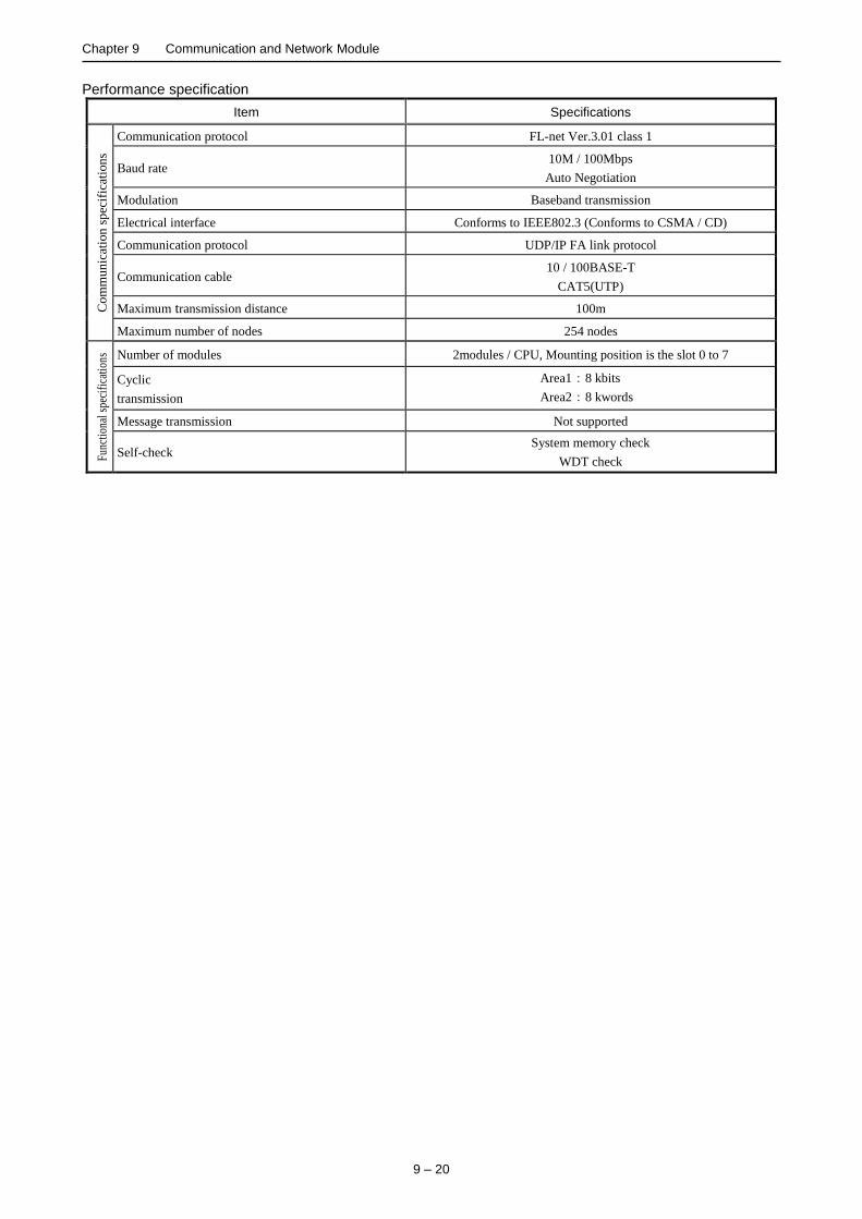
Chapter 9 Communication and Network Module
9 – 20
Performance specification
Item Specifications C
om
mu
nic
atio
n s
pec
ific
atio
ns
Communication protocol FL-net Ver.3.01 class 1
Baud rate 10M / 100Mbps
Auto Negotiation
Modulation Baseband transmission
Electrical interface Conforms to IEEE802.3 (Conforms to CSMA / CD)
Communication protocol UDP/IP FA link protocol
Communication cable 10 / 100BASE-T
CAT5(UTP)
Maximum transmission distance 100m
Maximum number of nodes 254 nodes
Func
tion
al s
peci
fica
tion
s Number of modules 2modules / CPU, Mounting position is the slot 0 to 7
Cyclic
transmission
Area1:8 kbits
Area2:8 kwords
Message transmission Not supported
Self-check System memory check
WDT check
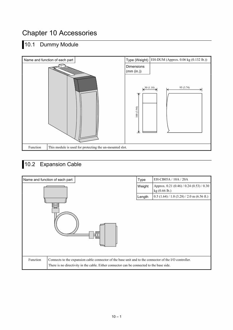
10 – 1
Chapter 10 Accessories 10.1 Dummy Module
Name and function of each part Type (Weight) EH-DUM (Approx. 0.06 kg (0.132 lb.))
Dimensions (mm (in.))
30 (1.18)
100
(3.9
4)
95 (3.74)
Function This module is used for protecting the un-mounted slot.
10.2 Expansion Cable
Name and function of each part Type EH-CB05A / 10A / 20A
Weight Approx. 0.21 (0.46) / 0.24 (0.53) / 0.30 kg (0.66 lb.)
Length 0.5 (1.64) / 1.0 (3.28) / 2.0 m (6.56 ft.)
Function Connects to the expansion cable connector of the base unit and to the connector of the I/O controller. There is no directivity in the cable. Either connector can be connected to the base side.
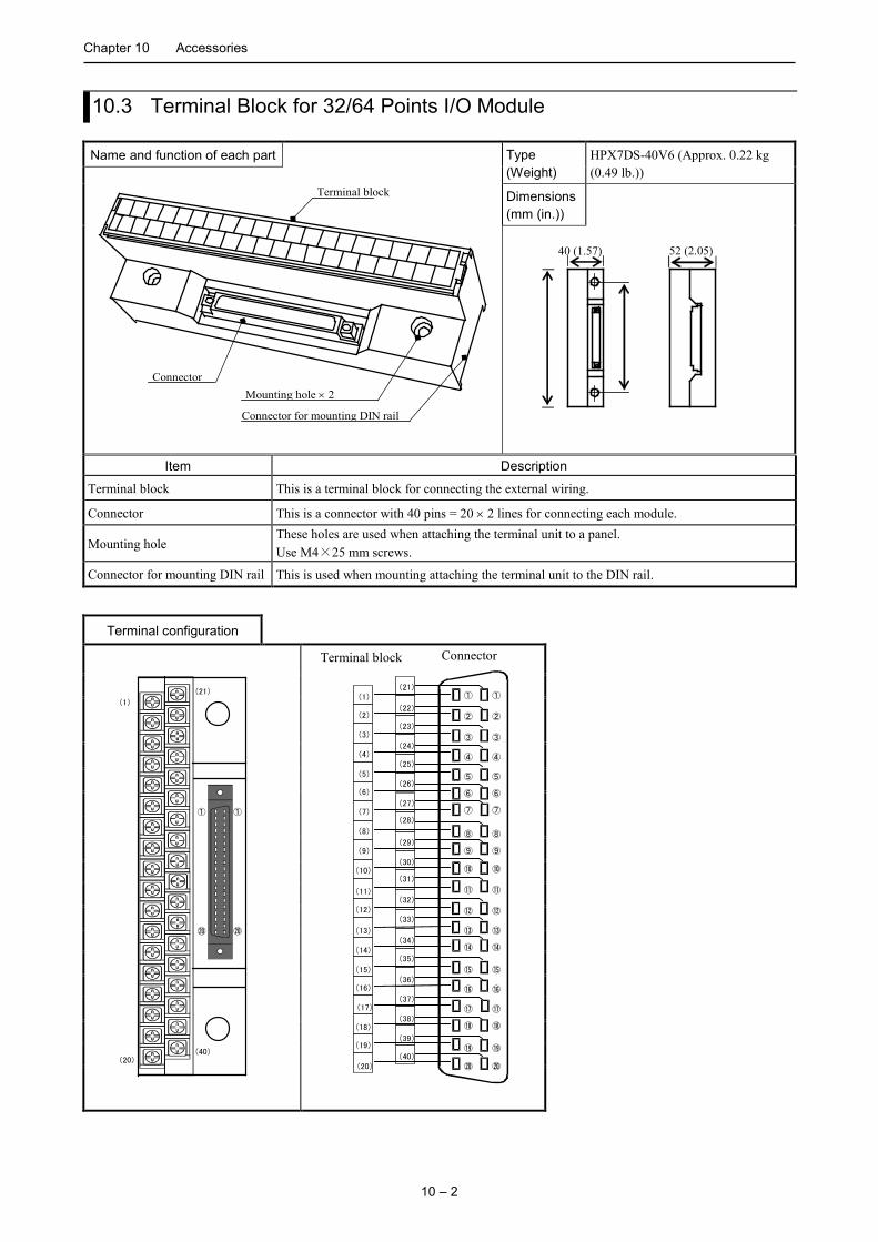
Chapter 10 Accessories
10 – 2
10.3 Terminal Block for 32/64 Points I/O Module
Name and function of each part Type (Weight)
HPX7DS-40V6 (Approx. 0.22 kg (0.49 lb.))
Connector
Terminal block
Mounting hole × 2
Connector for mounting DIN rail
Dimensions (mm (in.))
40 (1.57)
52 (2.05)
Item Description
Terminal block This is a terminal block for connecting the external wiring.
Connector This is a connector with 40 pins = 20 × 2 lines for connecting each module.
Mounting hole These holes are used when attaching the terminal unit to a panel. Use M4×25 mm screws.
Connector for mounting DIN rail This is used when mounting attaching the terminal unit to the DIN rail.
Terminal configuration
(21)
(40)
(1)
(20)
① ①
⑳ ⑳
(1) ①
(2)
(3)
(9)
(5)
(6)
(7)
(8)
(4)
(10)
(11)
(12)
(13)
(14)
(15)
(16)
(17)
(18)
(19)
(20)
(21)
(22)
(23)
(24)
(25)
(26)
(27)
(28)
(29)
(30)
(31)
(32)
(33)
(34)
(35)
(36)
(37)
(38)
(39)
(40)
①
② ②
③ ③
④ ④
⑤ ⑤
⑥ ⑥
⑦ ⑦
⑧ ⑧
⑨ ⑨
⑩ ⑩
⑪ ⑪
⑫ ⑫
⑬ ⑬
⑭ ⑭
⑮ ⑮
⑯ ⑯
⑰ ⑰
⑱ ⑱
⑲ ⑲
⑳ ⑳
Terminal block Connector
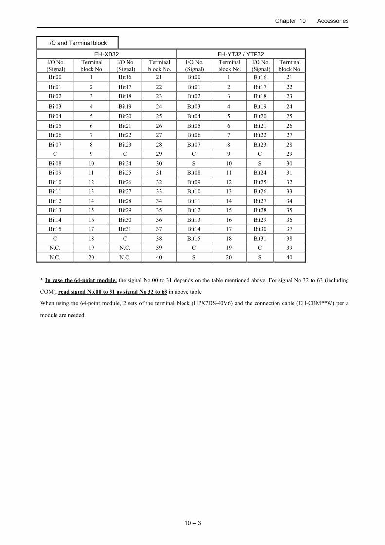
Chapter 10 Accessories
10 – 3
I/O and Terminal block
EH-XD32 EH-YT32 / YTP32 I/O No. (Signal)
Terminal block No.
I/O No. (Signal)
Terminal block No.
I/O No. (Signal)
Terminal block No.
I/O No. (Signal)
Terminal block No.
Bit00 1 Bit16 21 Bit00 1 Bit16 21
Bit01 2 Bit17 22 Bit01 2 Bit17 22 Bit02 3 Bit18 23 Bit02 3 Bit18 23
Bit03 4 Bit19 24 Bit03 4 Bit19 24
Bit04 5 Bit20 25 Bit04 5 Bit20 25 Bit05 6 Bit21 26 Bit05 6 Bit21 26 Bit06 7 Bit22 27 Bit06 7 Bit22 27 Bit07 8 Bit23 28 Bit07 8 Bit23 28
C 9 C 29 C 9 C 29 Bit08 10 Bit24 30 S 10 S 30 Bit09 11 Bit25 31 Bit08 11 Bit24 31 Bit10 12 Bit26 32 Bit09 12 Bit25 32 Bit11 13 Bit27 33 Bit10 13 Bit26 33 Bit12 14 Bit28 34 Bit11 14 Bit27 34 Bit13 15 Bit29 35 Bit12 15 Bit28 35 Bit14 16 Bit30 36 Bit13 16 Bit29 36 Bit15 17 Bit31 37 Bit14 17 Bit30 37
C 18 C 38 Bit15 18 Bit31 38 N.C. 19 N.C. 39 C 19 C 39 N.C. 20 N.C. 40 S 20 S 40
* In case the 64-point module, the signal No.00 to 31 depends on the table mentioned above. For signal No.32 to 63 (including
COM), read signal No.00 to 31 as signal No.32 to 63 in above table.
When using the 64-point module, 2 sets of the terminal block (HPX7DS-40V6) and the connection cable (EH-CBM**W) per a
module are needed.
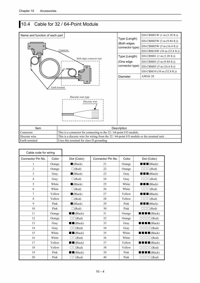
Chapter 10 Accessories
10 – 4
10.4 Cable for 32 / 64-Point Module
Name and function of each part Type (Length) (Both edges connector type)
EH-CBM01W (1 m (3.28 ft.))
Connector
Earth terminal
Both edges connector type
Discrete wire Discrete wire type
EH-CBM03W (3 m (9.84 ft.))
EH-CBM05W (5 m (16.4 ft.)) EH-CBM10W (10 m (32.8 ft.))
Type (Length) EH-CBM01 (1 m (3.28 ft.))
(One edge connector type)
EH-CBM03 (3 m (9.84 ft.)) EH-CBM05 (5 m (16.4 ft.)) EH-CBM10 (10 m (32.8 ft.))
Diameter AWG# 28
Item Description Connector This is a connector for connecting to the 32 / 64-point I/O module. Discrete wire This is a discrete wire for wiring from the 32 / 64-point I/O module or the terminal unit. Earth terminal Uses this terminal for class D grounding
Cable code for wiring
Connector Pin No. Color Dot (Color) Connector Pin No. Color Dot (Color)
1 Orange (Black) 21 Orange (Black) 2 Orange (Red) 22 Orange (Red) 3 Gray (Black) 23 Gray (Black)
4 Gray (Red) 24 Gray (Red)
5 White (Black) 25 White (Black) 6 White (Red) 26 White (Red) 7 Yellow (Black) 27 Yellow (Black) 8 Yellow (Red) 28 Yellow (Red) 9 Pink (Black) 29 Pink (Black)
10 Pink (Red) 30 Pink (Red) 11 Orange (Black) 31 Orange (Black) 12 Orange (Red) 32 Orange (Red) 13 Gray (Black) 33 Gray (Black) 14 Gray (Red) 34 Gray (Red) 15 White (Black) 35 White (Black) 16 White (Red) 36 White (Red) 17 Yellow (Black) 37 Yellow (Black) 18 Yellow (Red) 38 Yellow (Red) 19 Pink (Black) 39 Pink (Black) 20 Pink (Red) 40 Pink (Red)

Chapter 10 Accessories
10 – 5
10.5 Cable for Counter Input Module
Name and function of each part
Type (Length) (One edge connector type)
EH-CUC01 (1 m (3.28 ft.))
Connector Discrete wire
1
2
Wire No. corresponding to the terminal No. is
EH-CUC02 (2 m (6.56 ft.))
EH-CUC03 (3 m (9.84 ft.)) EH-CUC04 (4 m (13.1 ft.)) EH-CUC05 (5 m (16.4 ft.))
Diameter AWG# 24
Item Description Connector This is a connector for connecting to the counter input module. Discrete wire This is a discrete wire for wiring from the counter input module.

Chapter 10 Accessories
10 – 6
MEMO

11 – 1
Chapter 11 PAC Installation, Mounting, Wiring For safety use, avoid installing the PAC in the following locations.
- Excessive dusts, salty air, and / or conductive materials (iron powder, etc.)
- Direct sunlight
- Temperature less than 0 °C or more than 55 °C
- Dew condensation
- Humidity less than 5 % or more than 95 %
- Direct vibration and / or impact to the unit
- Corrosive, explosive and / or combustible gasses
- Water, chemicals and / or oil splashing on the PAC
- Close to noise emission devices
11.1 Installation
(1) Installing location and environment
(a) Use the module in the “3.1 General Specification” environment when installing the HX-CPU.
(b) Mount the PAC onto the metal plate.
(c) Install the PAC in a suitable enclosure such as a cabinet which opens with a key, tool, etc.
(2) Installation of a base unit
(a) Precaution when installing the base unit
1] Fix the base unit securely with screws in 4 places (M4, length 20 mm (0.79 in.)or longer) or DIN rail
when installing it.
2] To keep using the unit within the ambient temperature range.
a) Allow ample space for air circulation. (50 mm (1.97 in.) or more at top and bottom, 10 mm (0.39 in.) or
more at right and left)
b) Avoid installing the unit directly above equipment that generates a lot of heat (heater, transformer,
large-capacity resistance, etc.).
c) Install a fan or a cooler to lower the ambient temperature to below 55 °C when the temperature reaches
more than 55 °C.
3] Avoid mounting inside a panel where high-voltage equipment is installed.
4] Install 200 mm (7.87 in.) or more away from high-voltage wires or power wires.
5] Avoid mounting the unit upside down, in vertical, or in horizontal.
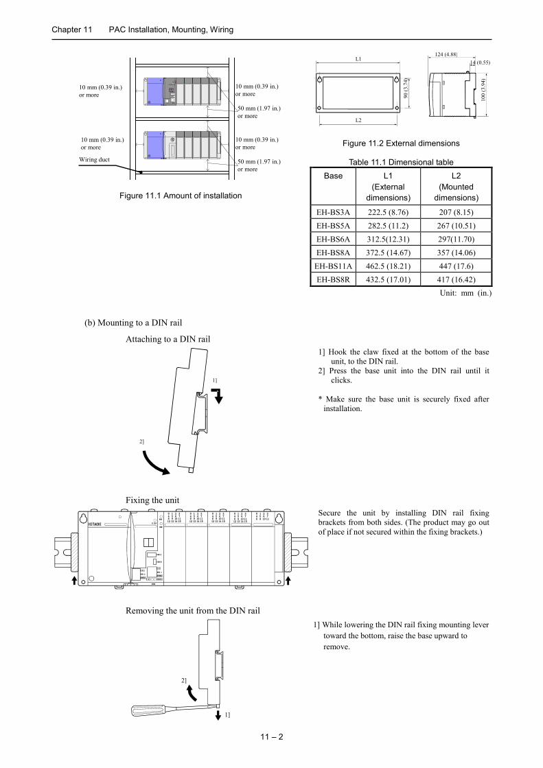
Chapter 11 PAC Installation, Mounting, Wiring
11 – 2
L1 124 (4.88)
100
(3.9
4)
14 (0.55)
L2
90 (3
.74)
Figure 11.2 External dimensions
Table 11.1 Dimensional table Base L1
(External dimensions)
L2 (Mounted
dimensions)
EH-BS3A 222.5 (8.76) 207 (8.15) EH-BS5A 282.5 (11.2) 267 (10.51) EH-BS6A 312.5(12.31) 297(11.70) EH-BS8A 372.5 (14.67) 357 (14.06) EH-BS11A 462.5 (18.21) 447 (17.6) EH-BS8R 432.5 (17.01) 417 (16.42)
Unit: mm (in.)
(b) Mounting to a DIN rail
Attaching to a DIN rail
2]
1]
1] Hook the claw fixed at the bottom of the base unit, to the DIN rail.
2] Press the base unit into the DIN rail until it clicks.
* Make sure the base unit is securely fixed after
installation.
Fixing the unit
0 1 2 3 4 5 6 7 8 9 10 11 12 13 14 15
0 1 2 3 4 5 6 7 8 9 10 11
USB-B
ETH 1
HITACHI 0 1 2 3 4 5 6 7 8 9 10 11 12 13 14 15
0 1 2 3 4 5 6 7 8 9 10 11 12 13 14 15
0 1 2 3 4 5 6 7 8 9 10 11 12 13 14 15
SPEED
L/A
ETH2
SPEED L/A
ETH 3
SPEED
L/A
USB-A
RUN
ERR
E.CLR
Secure the unit by installing DIN rail fixing brackets from both sides. (The product may go out of place if not secured within the fixing brackets.)
Removing the unit from the DIN rail
2]
1]
1] While lowering the DIN rail fixing mounting lever toward the bottom, raise the base upward to remove.
Wiring duct
10 mm (0.39 in.) or more
10 mm (0.39 in.) or more
10 mm (0.39 in.) or more
50 mm (1.97 in.) or more
10 mm (0.39 in.) or more
50 mm (1.97 in.) or more
Figure 11.1 Amount of installation
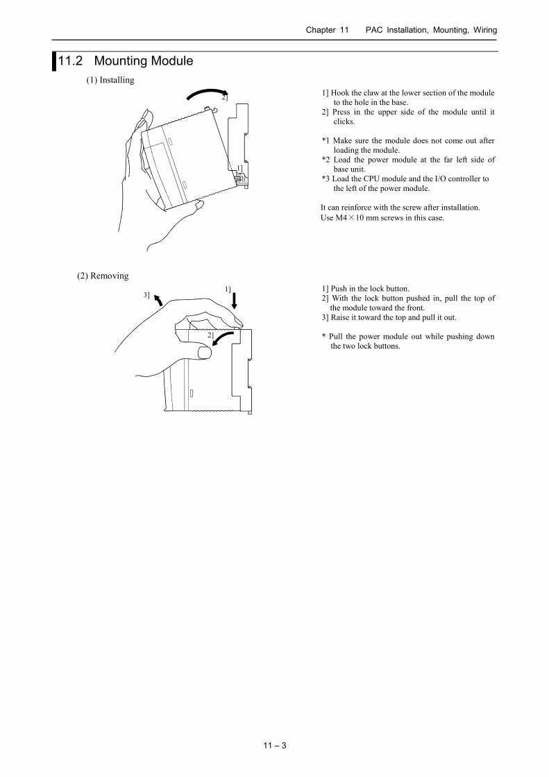
Chapter 11 PAC Installation, Mounting, Wiring
11 – 3
11.2 Mounting Module (1) Installing
2]
1]
1] Hook the claw at the lower section of the module to the hole in the base.
2] Press in the upper side of the module until it clicks.
*1 Make sure the module does not come out after
loading the module. *2 Load the power module at the far left side of
base unit. *3 Load the CPU module and the I/O controller to
the left of the power module. It can reinforce with the screw after installation. Use M4×10 mm screws in this case.
(2) Removing
2]
1] 3]
1] Push in the lock button. 2] With the lock button pushed in, pull the top of
the module toward the front. 3] Raise it toward the top and pull it out. * Pull the power module out while pushing down
the two lock buttons.

Chapter 11 PAC Installation, Mounting, Wiring
11 – 4
11.3 Wiring (1) Separation of the power system
There is power for the HX-CPU unit / power for I/O signal / power for general equipment as the power supply.
These power supplies should be wired from separate systems as much as possible.
When these power supplied are supplied from one main power source, separate the wiring with a transformer or
similar devices, so that each power supply is a separate system.
NF Main power supply 100 V AC
to 200 V AC
Transformer Power for HX-CPU unit
NF: Noise filter NF
Transformer Power for I/O signals
NF Power for general equipment
Figure 11.3 Example of power system diagram
(2) Regarding fail safe
1] Construct an interlock circuit outside the PAC.
When the PAC power supply is turned ON / OFF, the lag time and the difference in the startup time between
the PAC unit power and the external power (particular DC power supply) for the PAC I/O module signals
may temporarily cause the I/O not to operate normally.
Do not control the power for the EH-YR12 relays to have it perform an interlock with the external load, etc.
The relay may turn on even when the power has not been supplied by an aluminum electrolytic condenser
inside the module to drive the relay.
Also, it is conceivable that a fault in the external power and a failure in the PAC unit lead to abnormal
actions. To prevent such actions from causing abnormal operation in the entire system, and from a point of
view of creating a fail safe mechanism, construct ladder such as an emergency stop circuit, the protect
circuit, and the interlock circuit, for the sections that lead to a mechanical breakdown and accident from
abnormal actions outside the PAC.
2] Install a lightning arrester
To prevent damage to equipment as a result of being struck by lightning, we recommend setting up a
lightning arrester for each PAC power supply ladder.
The HX-CPU detects power failures from a voltage drop of the internal 5 V DC power supply. For this reason,
the load in the 5 V DC power of the unit is light, the 5 V DC is retained for a long time and operations may
continue for more than 100 ms. Therefore, when using the AC input module, an OFF delay timer for
coordinating with the internal 5 V DC is needed because the AC input signal turns off more quickly than the
internal.

Chapter 11 PAC Installation, Mounting, Wiring
11 – 5
(3) Wiring to the power module
0 1 4 5 8 9 12 13 HITACHI POWER
Power supply for sensor
Leak
100 V AC to 200 V AC
Noise filter
USB-B
ETH 1
SPEED
L/A
ETH2 SPEED
USB-A
L/A
RUN
ERR E.CLR
Insulation transformer with shield
Figure 11.4 Wiring power diagram
(a) For power supply wiring, use a cable of 2 mm2 (0.0031 in2.) or more to prevent a voltage drop from occurring.
(b) The function ground terminal (FE terminal) should use a cable of 2 mm2 (0.0031 in2) or more and Class D grounding (100 Ω or less). The appropriate distance for ground cable is within 20 m (65.62 ft.).
1] Shared with instrumentation panel, relay panel grounding.
2] Avoid joint grounding with equipment that can generate noise such as high-frequency heating furnace, large power panel (several kW or more), thyristor exchanger, electric welders, etc.
3] Be sure to connect a noise filter (NF) to the power cable.
(c) A terminal screw is an M3. Tighten screws within a torque range of 0.49 to 0.78 N・m when wiring.
(d) Use the same power supply system for the basic and expansion units.
(4) Wiring cable for I/O signals
Screw for each terminal is M3. Tighten within a torque range of 0.49 to 0.78 N・m. Use a crimp terminal with an outer diameter ot 6 mm (0.24 in.) or less when using it. Use only up to 2 crimp terminals in the same terminal. Avoid claming down more than 3 at the same time. Use a cable thickness of 0.75 mm2 (0.0011 in2.) at the maximum. (Use a 0.5 mm2 (0.00075 in2.) cable when adding 2 crimp terminals in the same terminal.) * Use shielded cable for the relay output module when corresponding to CE marking EMC command is necessary.
Attaching the terminal block
1]
4]
2]
3]
1] Align the tip of a terminal block mounting screw to the screw section of the I/O cover insertion fittings.
2] Push in the top of the terminal block until the I/O cover claw section locks with a click.
3] Tighten terminal block mounting screws while holding down the upper part of the terminal block.
4] Pull on the top of the terminal block to make cure that it is locked and cannot come out.
* Always reinstall it following the instructions above if the terminal block is removed.

Chapter 11 PAC Installation, Mounting, Wiring
11 – 6
(5) Input wiring for the input module
DC input
(EH-XD16、EH-XD8)
AC input
(EH-XA16、EH-XAH16)
1 2 3 4 5 6 7
8 9
10 11 12 13 14 15
C
0
C Current-output-type
proximity switch
24 V DC
(Example of EH-XD16)
+
1 2 3 4 5 6 7
8 9 10 11 12 13 14 15
C
0
C AC100 V
(Example of EH-XA16)
Figure 11.5 Input wiring
(a) DC input module
1] When all input terminal and the common terminal (C) are loaded with 24 V DC, the input changes to ON,
and approximately 6.9 mA current in case of EH-XD8, or approximately 4 mA current in case of
EH-XD16, flow to the external input contacts.
2] For sensors such as a proximity switch and photoelectric switch, current-output-type (transistor open
collector) can be directly connected. For voltage-output-type sensors, connect them to the input terminal
after first going through the transistor.
3] Measures to prevent contact failure in high load current contact.
High load
current contact
3 W 560
Approx. 50 mA
24 V DC
+
0
C
The current that flows to a contact when external contacts
are closed is approximately 6.9 mA for the EH-XD8, and
approximately 4 mA for EH-XD16. If it is necessary high
load current to the contact, add resistance as shown in the
diagram at left and supply sufficient current to the contact
to prevent a contact failure .
4] Limit the wiring length within 30 m (98.43 ft.).
(b) Wiring for 32 / 64-point input module (EH-XD32, EH-XD64) (Based on CE marking)
*1 Wire only the signal line through the shield cable, and provide class D grounding on the shield
cable side.
*2 Do not wire the common line or S terminal line through the shield cable. Be sure to wire them
independently and separately from the power line, I/O lines or power supply line.
*3 The supply line to the external power supply should be wired as close as possible to the common
terminal of the output module.
External power supply
0
1
2
31
C Common
terminal
Class D grounding
Signal line
Common line
Shield cable
+
+
EH-XD32 / 64

Chapter 11 PAC Installation, Mounting, Wiring
11 – 7
(c) AC input module
When using the AC input module, if the wiring route gets longer, voltage may be generated on the input
terminal though there are no actual signal, because the leak current may flow by the stray capacity between
wirings..
External device
AC input module
There are the following two methods 1] and 2] as its countermeasures. Please limit the voltage caused by the
electrostatic combination on the input terminal, to half the maximum OFF voltage level of the input module.
1] Lower impedance of the input module by connecting the dummy resistance with the input terminal in
parallel.
2] Connect the external power supply to the external device side.
External device
AC input module
Dummy resistance
(6) Output wiring for the output module
Item Relay output (EH-YR12)
Relay output (EH-YR16)
Transistor output (sink type)
(EH-YT16, EH-YT8)
Transistor output (source type)
(EH-YTP16、EH-YTP16S, EH-YTP8)
Exte
rnal
wiri
ng
+ -
NO NO
0 6
1 7
2 8
3 9
4 10
5 11
C C
FUSE
24 V DC 100 / 240 V AC
24 V DC + Surge killer
or Diode
0
8 1
9 2
10 3
11 4
12 5
13 6
14 7
15 C
C
FUSE
24 V DC 100 / 240 V AC
Surge killer or
Diode
0
8 1
9 2
10 3
11 4
12 5
13 6
14 7
15 C
S 12 / 24 V DC FUSE
Diode
+ (Example of EH-YT16)
0
8 1
9 2
10 3
11 4
12 5
13 6
14 7
15 C
S FUSE 12 / 24 V DC
Diode
+ (Example of EH-YTP16)
Figure 11.6 Output wiring

Chapter 11 PAC Installation, Mounting, Wiring
11 – 8
(a) Wiring for the relay output module
1] Life of relay contact Life curve of relay contact
1000 500
100
10
1 0.1 0.5 1 2
24 V DC L load
24 V DC R load 240 V AC R load
240 V AC L load Sw
itchi
ng li
fe (1
0,00
0 tim
es)
Shut-off current (A)
Life of the contact is also in squared reverse proportion to the current, so be aware that interrupting rush current or directly driving the condenser load will drastically reduce the life of the relay. When switching is done with high frequency, use a transistor output module.
2] Surge killer
For inductive load, connect a surge killer (condenser 0.1 µF, + resistance of around 100 Ω) in parallel to
the load. Also, for DC load, connect a flywheel diode.
3] Fuse
A fuse is not built in this module. Install a 6A fuse in the common to prevent the external wiring from
burning out.
4] Power supply for driving the relay
If a 24 V DC power supply is connected to drive the relay, take care with respect to the polarity when
connecting. There is a risk that the internal circuit will be damaged if the wiring is done incorrectly. Also,
do not perform an interlock, etc. to the external load with the power supply for driving the relay.
(b) Wiring for the transistor output module
1] Flywheel diode
For inductive load, connect a flywheel diode in parallel.
2] S and C terminals
Always connect an S terminal and C (common) terminal. If the module is used without connecting these
terminals, the internal flywheel diode does not function and there is a risk that the module will
malfunction or breakdown.
3] Fuse
A fuse is inserted in the common to prevent the external wiring from burning out, but this does not protect
transistor elements. Therefore, note that these elements are destroyed when the external load is
short-circuited. Please contact us for repair if the external load short-circuits.
Also, if the fuse blows, there will be no output even if the LED lights up. (The fuse out lamp for the
module at this time as well as a CPU module error will not be displayed.)
* If the fuse is melted or blown, do not supply power to the module after changing the fuse without
eliminating the source of the problem. Damage escalation, smoke, etc., may otherwise result.
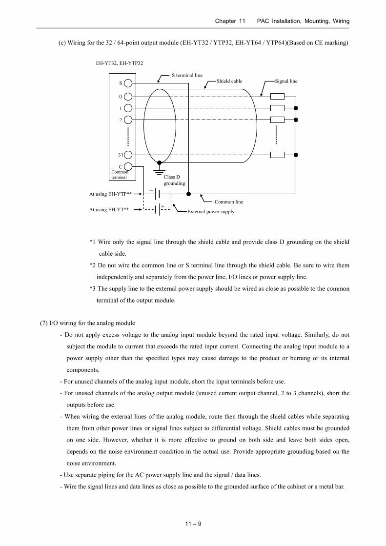
Chapter 11 PAC Installation, Mounting, Wiring
11 – 9
(c) Wiring for the 32 / 64-point output module (EH-YT32 / YTP32, EH-YT64 / YTP64)(Based on CE marking)
*1 Wire only the signal line through the shield cable and provide class D grounding on the shield
cable side.
*2 Do not wire the common line or S terminal line through the shield cable. Be sure to wire them
independently and separately from the power line, I/O lines or power supply line.
*3 The supply line to the external power supply should be wired as close as possible to the common
terminal of the output module.
(7) I/O wiring for the analog module
- Do not apply excess voltage to the analog input module beyond the rated input voltage. Similarly, do not
subject the module to current that exceeds the rated input current. Connecting the analog input module to a
power supply other than the specified types may cause damage to the product or burning or its internal
components.
- For unused channels of the analog input module, short the input terminals before use.
- For unused channels of the analog output module (unused current output channel, 2 to 3 channels), short the
outputs before use.
- When wiring the external lines of the analog module, route then through the shield cables while separating
them from other power lines or signal lines subject to differential voltage. Shield cables must be grounded
on one side. However, whether it is more effective to ground on both side and leave both sides open,
depends on the noise environment condition in the actual use. Provide appropriate grounding based on the
noise environment.
- Use separate piping for the AC power supply line and the signal / data lines.
- Wire the signal lines and data lines as close as possible to the grounded surface of the cabinet or a metal bar.
0
1
2
31
C Common terminal Class D
grounding
Signal line
Common line
External power supply
Shield cable
+
+
EH-YT32, EH-YTP32
S
S terminal line
At using EH-YTP**
At using EH-YT**
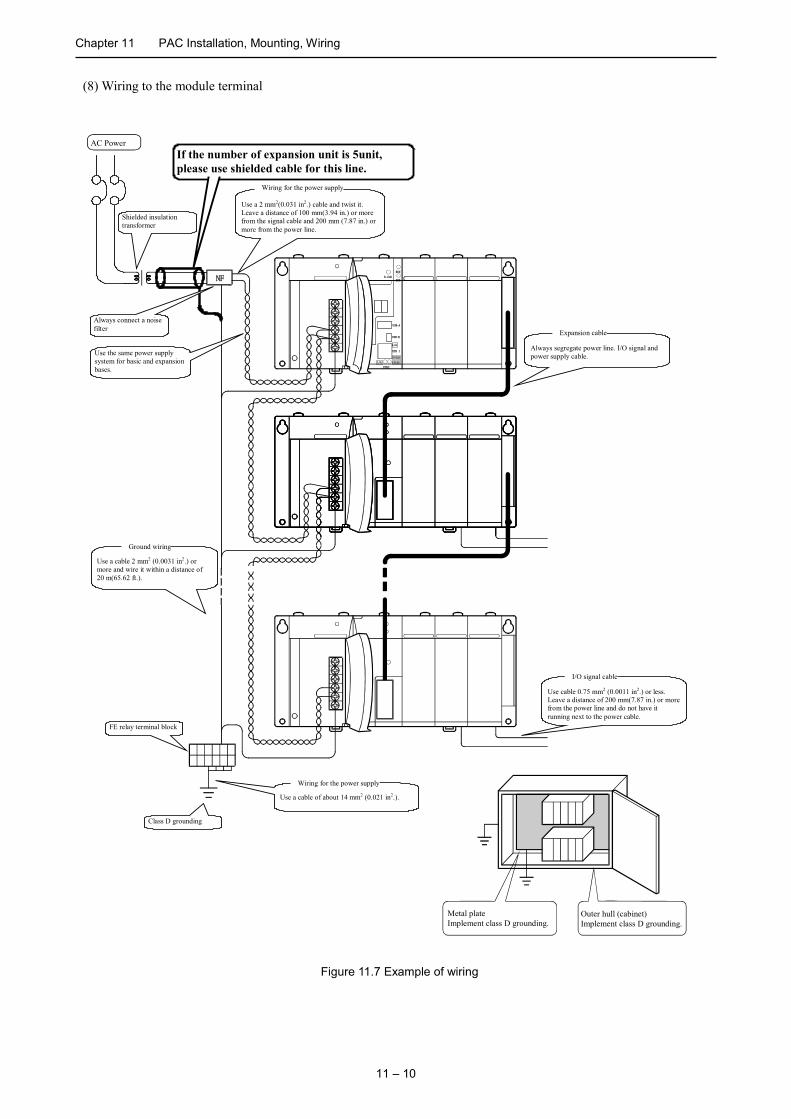
Chapter 11 PAC Installation, Mounting, Wiring
11 – 10
(8) Wiring to the module terminal
Metal plate Implement class D grounding.
Outer hull (cabinet) Implement class D grounding.
NF
AC Power
Shielded insulation transformer
Use a 2 mm2(0.031 in2.) cable and twist it. Leave a distance of 100 mm(3.94 in.) or more from the signal cable and 200 mm (7.87 in.) or more from the power line.
Wiring for the power supply
Always connect a noise filter
Use the same power supply system for basic and expansion bases.
Use a cable of about 14 mm2 (0.021 in2.).
Wiring for the power supply
Class D grounding
FE relay terminal block
Use cable 0.75 mm2 (0.0011 in2.) or less. Leave a distance of 200 mm(7.87 in.) or more from the power line and do not have it running next to the power cable.
I/O signal cable
Always segregate power line. I/O signal and power supply cable.
Expansion cable
Use a cable 2 mm2 (0.0031 in2.) or more and wire it within a distance of 20 m(65.62 ft.).
Ground wiring
If the number of expansion unit is 5unit, please use shielded cable for this line.
USB-B
ETH 1
SPEED
L/A
ETH2 SPEED
USB-A
L/A
RUN
ERR E.CLR
Figure 11.7 Example of wiring

12 – 1
Chapter 12 Maintenance and Inspection In order to use the HX-CPU functions in the most desirable condition and maintain the system to operate normally, it is
necessary to conduct daily and periodic inspections.
12.1 Daily and Periodic Inspection (1) Daily inspection
Verify the following items while the system is running.
Table 12.1 Items for daily inspection
Item LED display Inspection method
Normal status Main cause of error
Power module display POW Visual check ON Power supply error, etc. CPU module display RUN Visual check ON
(Running) OFF: Microprocessor error, memory error, etc. Refer to chapter 3 for further information.
ERR Visual check OFF ON: Serious errors such as microprocessor error or memory error, etc. Refer to chapter 3. Blink: 7x error
7-segment Visual check 00 Self-diagnosis error code is displayed. *1 If power off time is more than 1 week, realtime clock data could be lost due to super capacitor.
(2) Periodic inspection
Turn off the power for the external I/O circuit, and check the following items once every six months.
Table 12.2 Items for periodic inspection
Part Item Check criteria Remarks Programming device to CPU
Check the operation of the programming device
All switch and display lamps work properly.
Power supply Check for the voltage fluctuations EH-PSA, EH-PSR: 85 to 264 V AC EH-PSD: 21.6 to 26.4V DC
Tester
I/O module Output relay life Electrical life 200,000 times Mechanical life 10 million times
Refer to the relay contact file curve (chapter 11).
LED Turns ON / OFF correctly External power voltage Within the specification for each
I/O module. Refer to the specifications of I/O module
Battery (Lithium battery)
Check voltage and life ERR lamp flashes. Within 5 years after replacement.
Installation and connecting areas
(1) All module are securely fixed. (2) All command fits snugly. (3) All screw is tight. (4) All cables are normal.
No defects Tighten Check insertion Tighten Visual check
Ambient environment (1) Temperature (2) Humidity (3) Others
0 to 55 °C 5 to 95 % RH (no condensation) No dust, foreign matter, vibration
Visual check
Spare part Check the number of parts, the storage condition
No defects Visual check
Program Check program contents Compare the contents of the latest program saved and CPU contents, and make sure they are the same.
Check both master and backup.

Chapter 12 Maintenance and Inspection
12 – 2
12.2 Life of Product
The lifetime of electrolytic capacitors used in the power module is limited. Electrolytic capacitors are used in some of
I/O modules to improve noise resistance. If the lifetime is exceeded, performance of product is not guaranteed. Be sure
to conduct inspection and maintenance as follows.
(1) Power module
Many electrolytic capacitors are used in the power module. It is said that lifetime of electrolytic capacitor
would be half when ambient temperature increases 10 C.
If lifetime of electrolytic capacitor is exceeded, output power becomes unstable especially when output current
is high due to many point of outputs are activated for example.
Prepare spare units with considering 5 years lifetime in case ambient temperature is 30 C. For longer lifetime,
take account of installation location in terms of temperature and air circulation around power unit and.
(2) CPU module
Some electrolytic capacitors are used in CPU module also. If lifetime of electrolytic capacitor is exceeded,
more errors could happen since noise resistance is not enough. Be sure to overhaul CPU module periodically.
CPU module has a capacitor to maintain realtime clock data. Backup time with the capacitor is 7 days. The life
of the capacitor is approximately 31,000 hours, the ambient temperature influences the life of the capacitor.
When the capacitor is life, the backup time becomes short. When the time is not synchronous with a NTP
server. In the case of the following, use the battery.
- During the 8 days or more of a power cut, if the retention of realtime clock data is required
- When HX-CPU is used by more than 50 of environment.
Be noted following points about lifetime of battery.
- Refer to the following tables in the lifetime of the battery.
- When using the battery, enable the battery error detection. Refer to the manual section 2.6 Configuration
of HX series application manual (Software).
- The life time of the battery means the total time of interruption of power supply for PAC.
- When ERR LED is displayed flashing or the 7-segment LED is displayed 71, replace the battery within 7
days.
- The durable life of the battery is 5 years. Even if the battery is not a life, replace it every 5 years.
Battery life (Total power failure time)[Hr]
Guaranteed value (MIN) @55 C Actual value (MAX) @25 C
25,000 67,000

13 – 1
Chapter 13 Troubleshooting 13.1 Error Code HX-CPU has 7-segment display and error LED to indicate an error code as listed below. If two or more errors are detected at the same time, smaller error code has higher priority to be displayed. If error is detected, read the description following countermeasures depending on error level.
Error code Error level Countermeasure 88, 11 to 1F Serious error Cycle power. If it does not solve, contact your local supplier. 20 to 34 Exception Exception status is cleared only by Reset operation.
Execute Reset cold / warm / origin by HX-CODESYS 70 to 79 Warning User program execution does not stop by warning. If you need to activate alarm or
any action by warning, use CmpHIESErrors_HX library. Press E.CLR button to clear error code.
Err.
code
Error name
[Detected when]
Description PAC
System*
Applica-
tion
ERR
LED 88 Hardware watchdog
error [Always] The watchdog timer detected a microcomputer overload error because the microcomputer did not operate according to the system program.
Stop Stop
11 System ROM error (OS)
[Power on] Checksum value of system program (OS) in FLASH does not match the checksum calculated.
Stop Stop
12 Read / Write check failed
in RAM [Power on]
Read / write check for system RAM has failed. Stop Stop
17 System ROM error (File system) [Power on]
Checksum value of system program (File system) in FLASH does not match the checksum calculated.
Stop Stop
18 MAC address error
[Power on] MAC address is missing or wrong value. Stop Stop
1A Initialize failed in power
management device [Power on]
Initialization of power supply has failed. Stop Stop
1F Flash access failed [Power on]
Access to a FLASH memory has failed. Stop Stop
:ON, :Blink, :OFF * When a PAC system stops, because a system program of PAC stops, you can't communicate with HX-CODESYS.
7-segment LED
ERR LED (Red)
RUN LED (Green)
Error clear switch

Chapter 13 Troubleshooting
13 – 2
Err.
code
Error name
[Detected when]
Description PAC
System
Applica-
tion
ERR
LED 20 Illegal instruction
[Always] Illegal instruction was detected in a processor. Run Stop
21 Retain identify mismatch
[Power on] Error of checksum value for retain memory data was detected.
Run Stop
23 Unresolved external
references [Always]
A library doesn't exist in CPU. Run Stop
24 Software watchdog error
[Always] Actual cycle time has exceeded watchdog time. Set longer watchdog time.
Run Stop
25 Processorload watchdog
[Always] The processor load exceeded 80 %. Run Stop
27 Division by zero
[Always] The divisor of division command is 0 in IEC program.
Run Stop
28 FPU* Division by zero
[Always]
The divisor of division command is 0 in IEC program (FPU).
Run Stop
29 Access violation
[Always]
Access violation was detected in a processor. Run Stop
2A Overflow
[Always]
Overflow was detected in a processor. Run Stop
2B FPU* Overflow
[Always]
FPU overflow was detected in a processor. Run Stop
2C FPU* Underflow
[Always]
FPU underflow was detected in a processor. Run Stop
2E FPU* Invalid operation
[Always]
FPU Invalid operation was detected in a processor.
Run Stop
31 Load bootproject failed
[Power on]
Checksum value of user program in FLASH does not match the checksum calculated.
Run Stop
32 IoConfig Error
[Always]
The setting of modbus specification outside value was detected.
Run Stop
34 Config file Error
[Power on]
Config file Error was detected in a processor. Run Stop
* FPU means a Floating Point Unit of main processor in the HX-CPU.
:ON, :Blink, :OFF

Chapter 13 Troubleshooting
13 – 3
Err.
code
Error name
[Detected when]
Description PAC
System
Applica-
tion
ERR
LED 70 I/O Configuration Error
[Always] I/O configuration does not match with actual I/O modules.
Run Stop
71 Battery error [Always]
Battery voltage is low or battery is disconnected.
Run Stop
72 Special module failure [Always]
Hardware error is detected in special module or communication module.
Run Stop
74 Comm. module configuration error [Always]
Configuration error is detected in communication module.
Run Stop
77 FLASH writing failure [FLASH writing]
Failure has been detected in writing FLASH memory or the number of writing times (100,000 times) has been exceeded.
Run Stop
78 Checksum mismatch in
Flash (IP address) [Power on]
Checksum value of IP address in FLASH does not match the checksum calculated.
Run Stop
79 Realtime clock initialized [Power on]
Realtime clock was initialized, because power cut time exceeds the 7 days of the guarantee time.
Run Stop
:ON, :Blink, :OFF
* If error cause is removed, error code remains except for error code 71 (battery error).
71 Error and ERR LED blinking automatically disappear if battery is replaced to new one.
It's possible to invalidate I/O configuration Error detection and battery error detection in PAC Parameters setting.
For details, please refer to an application manual [Software].
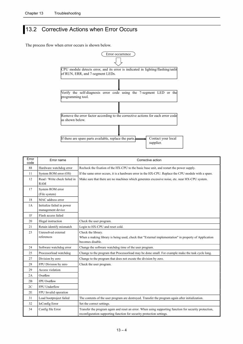
Chapter 13 Troubleshooting
13 – 4
13.2 Corrective Actions when Error Occurs
The process flow when error occurs is shown below.
CPU module detects error, and its error is indicated in lighting/flashing/unlit of RUN, ERR, and 7-segment LEDs.
Error occurrence
Verify the self-diagnosis error code using the 7-segment LED or the programming tool.
Remove the error factor according to the corrective actions for each error code as shown below.
If there are spare parts available, replace the parts. Contact your local supplier.
Error code
Error name Corrective action
88 Hardware watchdog error Recheck the fixation of the HX-CPU to the basic base unit, and restart the power supply.
11 System ROM error (OS) If the same error occurs, it is a hardware error in the HX-CPU. Replace the CPU module with a spare.
12 Read / Write check failed in RAM
Make sure that there are no machines which generates excessive noise, etc. near HX-CPU system.
17 System ROM error (File system)
18 MAC address error
1A Initialize failed in power management device
1F Flash access failed
20 Illegal instruction Check the user program.
21 Retain identify mismatch Login to HX-CPU and reset cold.
23 Unresolved external references
Check the library. When a making library is being used, check that "External implementation" in property of Application becomes disable.
24 Software watchdog error Change the software watchdog time of the user program.
25 Processorload watchdog Change to the program that Processorload may be done small. For example make the task cycle long.
27 Division by zero Change to the program that does not excute the division by zero.
28 FPU Division by zero Check the user program.
29 Access violation
2A Overflow
2B FPU Overflow
2C FPU Underflow
2E FPU Invalid operation
31 Load bootproject failed The contents of the user program are destroyed. Transfer the program again after initialization.
32 IoConfig Error Set the correct settings.
34 Config file Error Transfer the program again and reset an error. When using supporting function for security protection, reconfiguration supporting function for security protection settings.

Chapter 13 Troubleshooting
13 – 5
Error code
Error name Corrective action
70 I/O Configuration Error Check the I/O assignment once more. Recheck the fixation of each I/O module and I/O controller, and the connection of the expansion cable.
71 Battery error Replace the battery with a new one. Check the connection of the battery connector. When operating in the battery-less, set to disable the “Battery error detection”.
72 Special module failure Refer to the error code of the special module, perform the error recovery processing.
74 Comm. module configuration error
Refer to the error code of the comm module, perform the error recovery processing.
77 FLASH writing failure After the initialization, download the user program again. If the same error occurs, it is a hardware error in the CPU module. Replace the CPU module with a spare.
78 Checksum mismatch in Flash (IP address)
Set the IP address (ETH1, 2, 3) again.
79 Realtime clock initialized Set the time in the Realtime clock. Refer to ”SetDateAndTime” an application manual [Command references ].
Reseting the factory default settings When that does not solve the problem even after you restart and when the online connection to the HX-CODESYS has become impossible, it's possible to reset HX-CPU to factory default settings. < How to reset the factory default settings > (1) Remove power from the PAC. (2) Toggle the RUN / STOP switch to STOP position. (3) Turn on all 2 bits switches (SW1). (4) Supply power to the PAC with E.CLR button pressed until “SP” is displayed in the 7-segment LED.
(5) Toggle the RUN / STOP switch to RUN position. (6) It takes a few seconds to delete boot project. Then “Fn” is displayed in the 7-segment LED.
(7) Turn off all 2 bits switches (SW1).
When turning on the power next time, it starts with the factory default settings.
RUN / STOP switch
2-bit switch
Error clear switch
7-segment LED

Chapter 13 Troubleshooting
13 – 6
13.3 Error Libraries
As for warnings (error code 70 to 78), special libraries called “CmpHIESErrors_HX” are available as below. Use them
in your application program if necessary. If it is not registered in your library repository, install
CmpHIESErrors_HX.compiled-library by choosing [Tools]-[Install library...].
Error
code
Libraries (CmpHIESErrors_HX) Input Output
all
- Last detected error code
(WORD)
All
Execution bit to
clear error code
(BOOL)
Result (BOOL)
70
(FB)
- 70 Error bit (BOOL)
Unit number (WORD)
Slot number (WORD)
71
- 71 Error bit (BOOL)
72
(FB)
- 72 Error bit (BOOL)
Unit number (WORD)
Slot number (WORD)
74
(FB)
- 74 Error bit (BOOL)
Unit number (WORD)
Slot number (WORD)
77
- 77 Error bit (BOOL)
78
- 78 Error bit (BOOL)