highway plan reading manual - pages · highway plan reading manual ... plan signatures and notes...
TRANSCRIPT
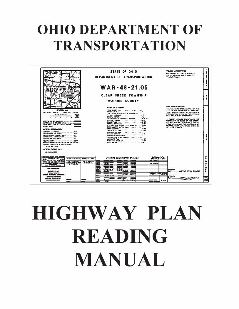
OHIO DEPARTMENT OF
TRANSPORTATION
HIGHWAY PLAN
READING
MANUAL

Highway Plan
Reading
Manual
Ohio Department of Transportation
Office of Production
An Equal Opportunity Employer
Highway Plan Reading Manual February, 2014
i
TABLE OF CONTENTS
ACKNOWLEDGMENTS ......................................................................... 1
STATE MAP ............................................................................................. 2
GENERAL INTRODUCTION ................................................................. 3
PART I: CONSTRUCTION PLANS ...................................................................... 4
1. TITLE SHEET ............................................................................................ 5
A. Project Designation ......................................................................... 5 B. Project Description .......................................................................... 6 C. Location Map & Scale ..................................................................... 6 D. Design Designation and Design Exceptions ................................... 7 E. Index of Sheets ............................................................................... 7 F. Standard Drawings and Supplemental Specifications .................... 7 G. Limited Access Declaration, Plan Signatures and Notes ................ 7 H. Title Block ....................................................................................... 8
2. SCHEMATIC PLAN ................................................................................... 8
A. Alignment ........................................................................................ 8 B. Stationing ........................................................................................ 9 C. Project and Work Limits .................................................................. 9 D. Curve Data .................................................................................... 10 E. Centerline References .................................................................. 10
Quiz 1............................................................................................ 11
3. UTILITY PLAN ........................................................................................ 12
4. TYPICAL SECTIONS .............................................................................. 12
A. Sections and Stationing ................................................................ 12 B. Horizontal and Vertical Dimensions .............................................. 12 C. Slopes ........................................................................................... 13 D. Superelevation .............................................................................. 13 E. Profile Grade Line ......................................................................... 14 F. Pavement Build-up ........................................................................ 14 G. Legend .......................................................................................... 14
Quiz 2............................................................................................ 15
5. GENERAL NOTES .................................................................................. 16
6. MAINTENANCE OF TRAFFIC PLANS ................................................... 16

Highway Plan Reading Manual February, 2014
ii
7. GENERAL SUMMARY ............................................................................ 16
8. PROJECT SITE PLAN ............................................................................ 16
Quiz 3 ................................................................................. 17
9. PLAN AND PROFILE SHEETS ............................................................... 18
A. Plan View ...................................................................................... 18 1. Standard CADD/Drafting Symbols ..................................... 18 2. Scale .................................................................................. 18 3. Station and Offset .............................................................. 18 4. Bearings ............................................................................. 19 5. Horizontal Curves ............................................................... 19 6. Items of Work ..................................................................... 20
B. Profile View ................................................................................... 21 1. Scale .................................................................................. 22 2. Station and Elevation ......................................................... 22 3. Profile Grade Line .............................................................. 22 4. Slopes and Grades ............................................................ 23 5. Vertical Curves ................................................................... 23 6. Drainage and Utilities ......................................................... 24
Quiz 4 ................................................................................. 24
10. CROSS SECTIONS .............................................................................. 25
A. Scales ........................................................................................... 25 B. Station and Offset ......................................................................... 25 C. Slopes ........................................................................................... 26 D. Existing and Proposed Right of Way ............................................ 26 E. Drainage and Utilities.................................................................... 26 F. Seeding and Earthwork ................................................................. 27 G. Partial Sections ............................................................................. 27
Quiz 5............................................................................................ 28
11. MISCELLANEOUS DETAILS .............................................................. 29
A. Drive Details ................................................................................. 29 B. Drainage Details ........................................................................... 30
12. SIGNING AND PAVEMENT MARKING PLAN .................................. 30
Highway Plan Reading Manual February, 2014
iii
PART II: RIGHT OF WAY PLANS ................................................................... 31
1. LEGEND SHEET ................................................................................... 31
A. Index of Sheets ............................................................................. 31 B. Structure Key ................................................................................ 32 C. Utility Easement, List and Note ..................................................... 32 D. Conventional Symbols .................................................................. 32 E. Project Description ........................................................................ 32 F. Plans Prepared By ........................................................................ 32 E. Survey Certification ....................................................................... 33 F. Parcel Identifier Legend ................................................................ 33
2. CENTERLINE PLAT ............................................................................. 33
A. Local Orientation ........................................................................... 33 B. Centerline Monumentation ............................................................ 34 C. Public Land Surveys and Political Subdivision Boundaries .......... 34 D. Basis for Bearings ......................................................................... 34 E. Survey Certification ....................................................................... 35 F. Recording Block ............................................................................ 35
Quiz 6............................................................................................ 36
3. PROPERTY MAP .................................................................................. 37
A. Ownership Name and Number ...................................................... 37 B. Property Lines ............................................................................... 37 C. Public Land Surveys and Political Subdivision Boundaries .......... 37 D. Buildings, Structures and Drives ................................................... 37 E. Limit Flags..................................................................................... 39 F. Service Roads ............................................................................... 39 G. Landlocked Parcels or Residues .................................................. 39
4. UTILITY PLAN ....................................................................................... 39
Quiz 7............................................................................................ 40
5. SUMMARY OF ADDITIONAL RIGHT OF WAY SHEET ................... 41
A. Parcel Number and Owner Identification ...................................... 41 B. Owners Record ............................................................................. 41 C. Auditor=s Parcel Number .............................................................. 41
D. Record Area .................................................................................. 42 E. Total PRO ..................................................................................... 42 F. Take Areas and Residuals ............................................................ 42 G. Funding ......................................................................................... 44 H. Temporary Parcel Duration ........................................................... 44 I. Encroachments ............................................................................. 44
Quiz 8............................................................................................ 45
Highway Plan Reading Manual February, 2014
iv
6. SCHEMATIC PLAN............................................................................... 46
7. DETAIL RIGHT OF WAY PLAN SHEETS .......................................... 46
A. Local Orientation ........................................................................... 46 B. Existing Topographic Features ..................................................... 46 C. Utilities .......................................................................................... 46 D. Waterways and Railroads ............................................................. 47 E. Land Use ....................................................................................... 47 F. Property Lines ............................................................................... 48 G. Survey Data .................................................................................. 49 H Right of Way Limits ....................................................................... 49 I. Station and Offset ......................................................................... 49 J. Parcel Balloons ............................................................................. 49 K. Items of Work ................................................................................ 49 L. Right of Way Fence ...................................................................... 50 M. Construction Limits ....................................................................... 50
Quiz 9............................................................................................ 51
APPENDIXES
A. County Abbreviations ......................................................................................... 53 B. Scales ................................................................................................................. 55
Practice in using the Scale ................................................................................. 56 C. Parcel Identifiers ................................................................................................ 57 D. Sample Legal Description and Plat .................................................................... 64

Highway Plan Reading Manual February, 2014
1
ACKNOWLEDGMENTS
Various resources were consulted during the development of this revision to the Highway Plan Reading Manual. The original manual was utilized in part for it’s presentation style which included course material followed by quiz inserts. Construction and right of way plans that were more recently developed were selected to be included in the manual plan set to better reflect current plan preparation techniques. Current ODOT standards were researched and applied to update a majority of the course material included in the original manual. The following is a list of the ODOT standards that were consulted:
The Real Estate Policies and Procedures Manual
The Right of Way Manual
The Location and Design Manual
The Location and Design Sample Plan Sheets
Survey & Mapping Specifications
The Highway Plan Reading Manual
The Standard Construction Drawings
The Construction and Material Specifications
The Supplemental Specifications
The CADD Engineering Standards Manual
THE OHIO DEPARTMENT OF TRANSPORTATION OFFICE OF PRODUCTION
REVISED February, 2014
Highway Plan Reading Manual February, 2014
2
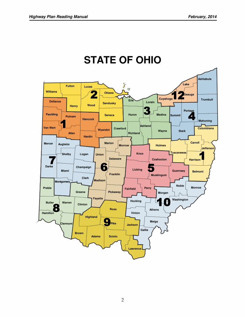
2222
1111
7777
8888
9999
11110000
6666
3333
5555
1111
4444
12121212
MadisonMontgomery
Clermont
Cuyahoga Erie
Huron
Lorain
Geauga
Portage
Ashtabula
Trumbull
Medina
Wayne Stark
Mahoning
Holmes
Columbiana
Carroll
Delaware
Marion
Hardin
Union
Fayette
Knox
Coshocton
Licking
Morgan
Perry Fairfield
Hocking
Ross
Pike
Franklin
Noble
Guernsey
Harrison
Belmont
Monroe
Athens Vinton
Meigs
Gallia
Hamilton
Clinton Butler Warren
Brown Adams
Highland
Auglaize
Miami
Shelby
Paulding
Van Wert
Allen
Mercer
Darke
Logan
Champaign
Clark
Preble Greene
Hancock
Wyandot
Ottawa
Sandusky
Seneca
Wood
Lucas
Williams
Defiance Henry
Fulton
Putnam
Pickaway
Lawrence
Jackson
Washington
Tuscarawas
Summit
Lake
Richland
Crawford
Morrow
Muskingum
Scioto
Ashland
Jefferson
STATE OF OHIO
Highway Plan Reading Manual February, 2014
3
GENERAL INTRODUCTION
Highway plans are developed to provide a pictorial view of the existing facilities and proposed improvements on a particular portion of roadway. They convey information about the construction project itself ranging from the amount of construction materials used on the project to the amount of land necessary to accommodate the work. Various sections make up a complete set of highway plans and those that are included depend on the type of construction taking place. Many highway plan sets have sections on roadway items, erosion control, drainage, pavement, maintenance of traffic, traffic control, lighting, landscaping and right of way. ODOT separates its highway plans into two main categories; the construction portion of the plan set and right of way portion of the plan set. These areas are seen as two distinctly different development phases but must be combined together to form the overall highway plan. The construction portion of the plan set is used to convey information about the design of the roadway itself, the amount and type of construction materials used for the project and the types of construction methods used to complete the work. Designers, estimators and construction workers all use the construction plans to assist them with their work when determining current standards, estimating the cost of the project or constructing the improvement. The right of way portion of the plan set is used to convey information about the right of way boundaries and adjacent property lines, the property ownerships and acreage involved in the takes and the overall impact the improvement will have to the particular property owners. Appraisers, negotiators and attorneys all use the right of way plans to assist them with their work when determining fair market value, negotiating with the property owner or explaining a condemnation case to a jury. ODOT has numerous standards that apply when preparing a set of highway plans. In general, the Location and Design Manuals provide information on current roadway and drainage design standards and general plan preparation techniques. The Right of Way Plan Manual provides information on current right of way standards, right of way plan preparation techniques and includes sample right of way plan sheets for reference purposes. Each highway plan should be prepared in accordance with these standards and, in addition, should utilize standard drafting and design symbols as presented in the CADD Engineering Standards Manual in order to provide a uniform format for conveying information that is easily understood by all users.
Highway Plan Reading Manual February, 2014
4
This manual has been prepared to introduce the general aspects of highway plan preparation techniques and to assist in the interpretation of both construction and right of way plans. Since different standards have been applicable throughout the years, no two highway plans may look identical. However, with additional exposure to various types of highway plans coupled with the general plan preparation information provided in this course, any individual should be able to methodically interpret and easily understand the information being conveyed in any highway plan set they encounter.
PART I: CONSTRUCTION PLANS
The construction plans form the foundation of a standard set of highway plans. The plans are usually developed by various design professionals. ODOT uses in-house designers and outside consultants to prepare construction plans. Construction plans provide users with detailed, technical information regarding the type of work being performed on a construction project. Construction plans are a very important part of the project development process on the whole. Contractors, as well as various subcontractors, utilize construction plans in order to construct the project. Estimators use construction plans to assign a reasonable cost associated with the work required to complete the project. The plan set serves as a public record showing the documented centerline of a roadway and all associated information. Every set of construction plans contains certain standard information that provides insight into the type of work and the method of construction used to complete the project. Each project may have unique features and, as such, may require special additions, such as details, notes, etc. Most construction plans contain a title sheet, a schematic plan, typical sections, general notes, maintenance of traffic sheets, estimated quantities, plan and profile sheets, cross sections, traffic control and miscellaneous details such as drainage details, drive details, etc. The information provided in this section will help to acquaint you with the different parts that are developed and assembled to form a construction plan and will assist you in interpreting the roadway details presented.

Highway Plan Reading Manual February, 2014
5
1. TITLE SHEET
The first sheet in your set of plans is called the TITLE SHEET. The title sheet gives a brief description of the work involved and includes the following:
• Indicates the length of the project • Shows the general location of the project • Sets up the specifications under which the project is to be built • States whether traffic is to be maintained or detoured • Gives an index of all sheets in the plan • Lists standard construction drawings and supplemental specifications • Contains the signature of approval by the proper officials
A. Project Designation
The project designation consists of three parts: County Route Section
WAR - 48 - 21.05
a. County (WAR) - The county (or counties) in which the project is located is identified by an abbreviation consisting of three letters. The abbreviations for each county are shown in Appendix A.
b. Route (48) - The route number is identified as the actual route number assigned to the highway on which the improvement is located.
c. Section Number (21.05) - The section number is determined by the straight line mileage (SLM). This is the distance in miles measured along the centerline1 of the highway from the point where the highway enters the
county, starting from west to east for east-west routes or from south to north for north-south routes. The (SLM) is accurate to the nearest hundredth of a mile (0.01).
When a project extends into an adjacent county, a project designation must be shown for each county. For example Counties Route Section
FRA/DEL - 3 – 26.18/0.00
1The centerline is defined as a line which serves as a horizontal base of reference for the
construction and right of way on a given project.
Highway Plan Reading Manual February, 2014
6
B. Project Description The project description is a brief paragraph describing the primary purpose of the improvement and shows the project length. The project length is the total distance between the beginning and ending project points. In addition, the project description includes other incidental construction. Incidental construction may include the following items: bridge work, interchanges, major connecting roads, lighting, traffic control, etc. (unless they are included in the primary construction).
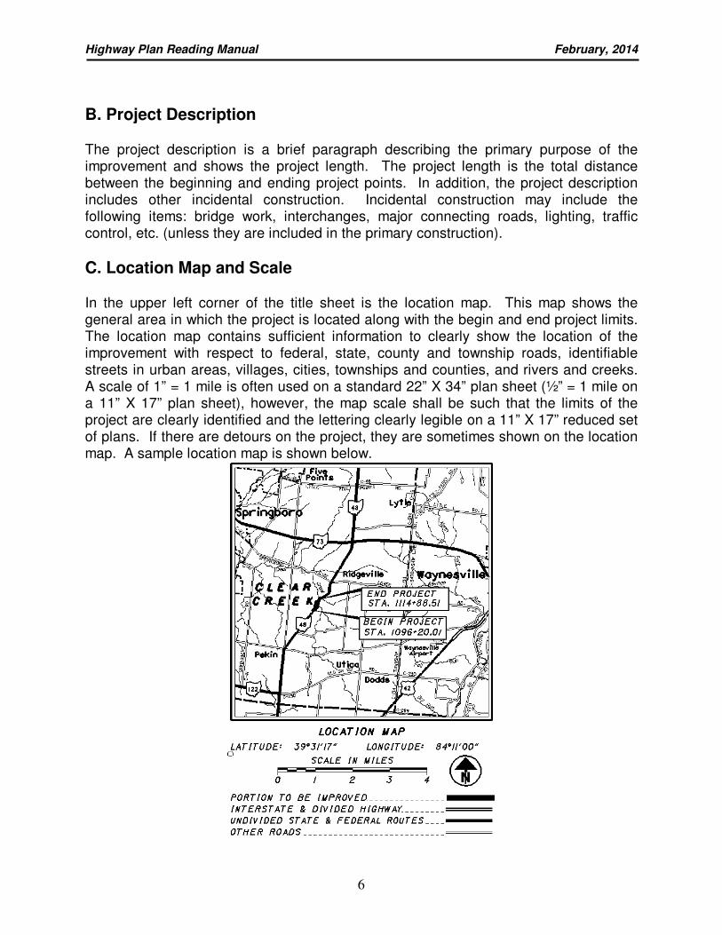
C. Location Map and Scale In the upper left corner of the title sheet is the location map. This map shows the general area in which the project is located along with the begin and end project limits. The location map contains sufficient information to clearly show the location of the improvement with respect to federal, state, county and township roads, identifiable streets in urban areas, villages, cities, townships and counties, and rivers and creeks. A scale of 1” = 1 mile is often used on a standard 22” X 34” plan sheet (½” = 1 mile on a 11” X 17” plan sheet), however, the map scale shall be such that the limits of the project are clearly identified and the lettering clearly legible on a 11” X 17” reduced set of plans. If there are detours on the project, they are sometimes shown on the location map. A sample location map is shown below.
Highway Plan Reading Manual February, 2014
7
D. Design Designation and Design Exceptions The design designation is an expression of the basic factors which control the design of the highway (i.e. average daily traffic (ADT), design speed, percentage of truck traffic, etc.). It may be included in the plan for any type of construction project, but it is required on any improvement having pavement work or geometric changes. If only one design designation is used, it is shown on the title sheet. Projects involving interchanges, major intersections, or other major traffic generators that affect traffic volumes require additional design designations. On improvements requiring more than one design designation, they are shown on a special sheet or on the Schematic Plan with the location noted in the index of sheets. A design exception is identified on the title sheet and on the appropriate plan sheet in the construction plan when the designer can not meet the normal design criteria. If there are no design exceptions, it will be identified as “None Required” on the title sheet.
E. Index of Sheets The index of sheets serves as a table of contents for the entire set of plans. Soil profile and structure foundation sheets are shown in the index of sheets but are not numbered. Sheet numbers that are not used are noted as “Not Used.” In rare circumstances, sheets may be inserted into the plan by alphabetizing (Example: 88A, 88B, 88C, etc.). All alphabetized sheets should be shown in the Index of Sheets.
F. Standard Drawings and Supplemental Specifications ODOT publishes three sets (Roadway, Bridge, and Traffic) of “STANDARD CONSTRUCTION DRAWINGS” that list the drawings individually and show the dates on which the drawings were last approved or revised. Standard drawings are used by production engineers to standardize various types of construction items, construction methods and construction activities. The approval and revision date are listed so that the contractor can determine that he or she has the specific drawings to which the designer makes reference. The supplemental specifications are detailed specifications supplementing to or superseding the construction and material specifications and the standard construction drawings.
G. Limited Access Declaration, Plan Signatures and Notes The limited access note is shown on the title sheet when either the existing or proposed right-of-way is designated as limited access.
Highway Plan Reading Manual February, 2014
8
Plan signatures are listed along the right side of the title sheet. A series of approval spaces are shown that are signed by the appropriate officials of the agencies involved. Any additional notes that are important to the entire plan may be shown on the right side of the title sheet. These items may be in the form of specification notes, maintenance of traffic notes, etc.
H. Title Block All plan sheets display a title block that will have all or part of the following information:
• Plan Sheet Number • Project Designation • Sheet Title • Railroad Involvement • Construction Project Number
• PID Number • Federal Project Number • Quantity Validation • Plan Scales • North Arrow
2. SCHEMATIC PLAN The Schematic Plan shows the geometric location of the proposed roadway segments in relation to the existing roadway segments, as well as other significant features. All projects include a Schematic Plan unless the project is short enough to be shown entirely on less than four plan and profile sheet. The Schematic Plans are normally prepared to a scale of 1”=100, 1”=200’ or 1”=400’ and are usually shown on one or two sheets.
A. Alignment A line drawn from point A to point B (or from a beginning point to an ending point) where all the information to the right and left of the line is referenced is called an alignment. There are two types of highway alignments, namely, the horizontal and the vertical alignments. The horizontal alignment controls the lateral location of the highway. The vertical alignment controls the rise or fall of the highway.
Highway Plan Reading Manual February, 2014
9
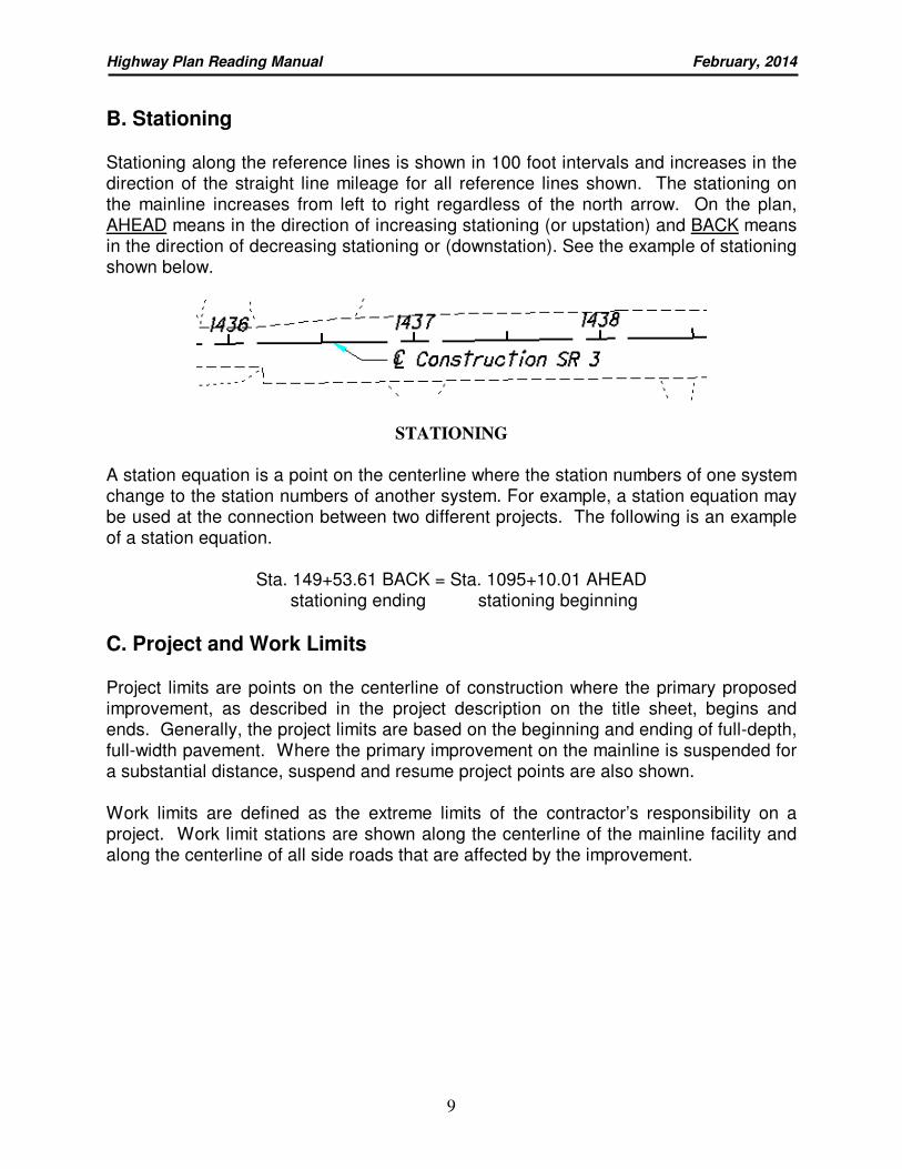
B. Stationing Stationing along the reference lines is shown in 100 foot intervals and increases in the direction of the straight line mileage for all reference lines shown. The stationing on the mainline increases from left to right regardless of the north arrow. On the plan, AHEAD means in the direction of increasing stationing (or upstation) and BACK means in the direction of decreasing stationing or (downstation). See the example of stationing shown below.
STATIONING A station equation is a point on the centerline where the station numbers of one system change to the station numbers of another system. For example, a station equation may be used at the connection between two different projects. The following is an example of a station equation.
Sta. 149+53.61 BACK = Sta. 1095+10.01 AHEAD stationing ending stationing beginning
C. Project and Work Limits
Project limits are points on the centerline of construction where the primary proposed improvement, as described in the project description on the title sheet, begins and ends. Generally, the project limits are based on the beginning and ending of full-depth, full-width pavement. Where the primary improvement on the mainline is suspended for a substantial distance, suspend and resume project points are also shown. Work limits are defined as the extreme limits of the contractor’s responsibility on a project. Work limit stations are shown along the centerline of the mainline facility and along the centerline of all side roads that are affected by the improvement.
Highway Plan Reading Manual February, 2014
10
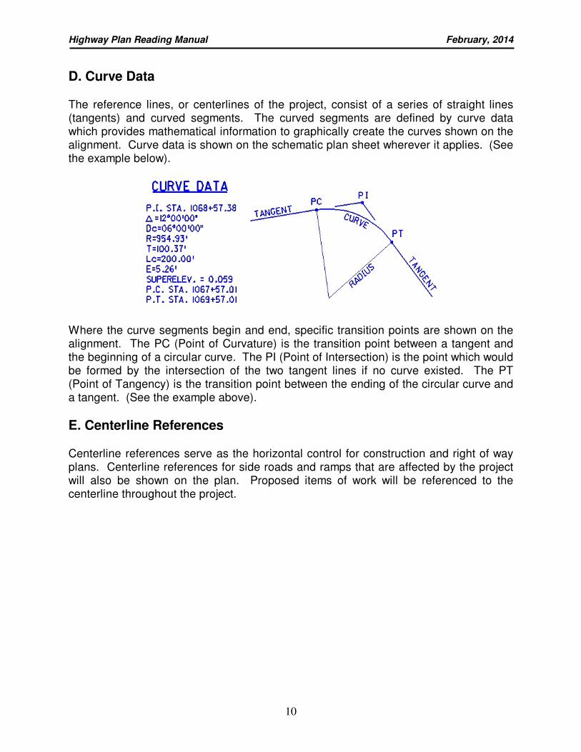
D. Curve Data
The reference lines, or centerlines of the project, consist of a series of straight lines (tangents) and curved segments. The curved segments are defined by curve data which provides mathematical information to graphically create the curves shown on the alignment. Curve data is shown on the schematic plan sheet wherever it applies. (See the example below).
Where the curve segments begin and end, specific transition points are shown on the alignment. The PC (Point of Curvature) is the transition point between a tangent and the beginning of a circular curve. The PI (Point of Intersection) is the point which would be formed by the intersection of the two tangent lines if no curve existed. The PT (Point of Tangency) is the transition point between the ending of the circular curve and a tangent. (See the example above).
E. Centerline References Centerline references serve as the horizontal control for construction and right of way plans. Centerline references for side roads and ramps that are affected by the project will also be shown on the plan. Proposed items of work will be referenced to the centerline throughout the project.
Highway Plan Reading Manual February, 2014
11
QUIZ 1
Using the WAR-48-21.05 Title and Schematic Plan, answer the following: 1. What is the complete project designation (CRS) for the project plans used in this
course? ______________________________________________________
2. The Right of Way is located on what sheet numbers? _____________________
3. What is the year of the specifications that apply to this project?
______________
4. What is the primary purpose of this project? _____________________________
________________________________________________________________
5. What is the project PID number? _______________
6. What is the design speed of S. R. 48? ________________
7. (a) What is the “Begin Project” station for this project? _____________________
(b) What is the “End Work” station for this project? _______________________
8. Is there a waterway that crosses the centerline of S. R. 48? _________
If so, what is the name of this waterway? _______________________________
9. What are the stations of the PI for Curve #1 and Curve #2?
Curve #1 ______________________ Curve #2 ________________________
10. Are there any station equations located on the centerline of this project? ______
If so, what are they? _______________________________________________
________________________________________________________________
Highway Plan Reading Manual February, 2014
12
3. UTILITY PLAN
Depending on the complexity of the project and/or the number of utilities affected and their involvement, a utility plan sheet may be included in either the construction plan sheets or the right of way plan sheets. If a separate utility plan sheet is not required, all utility companies involved are listed in the general notes of the construction section and the same data is shown on the legend sheet of the right of way section.
4. TYPICAL SECTIONS
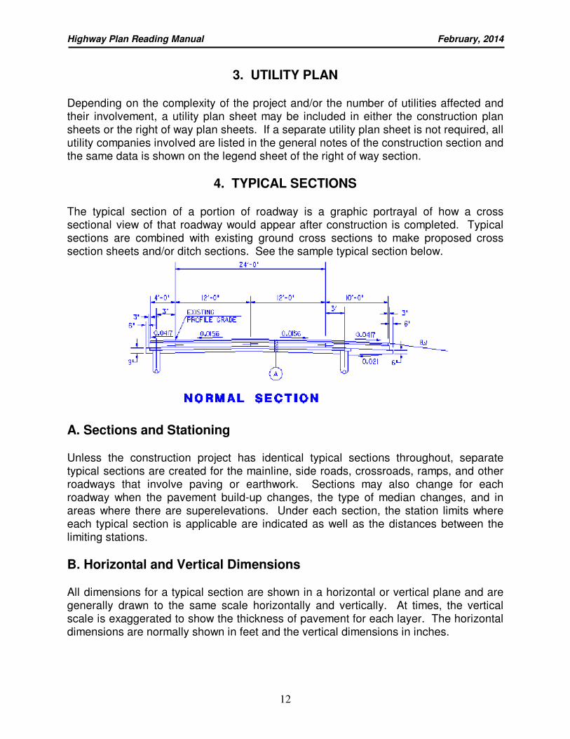
The typical section of a portion of roadway is a graphic portrayal of how a cross sectional view of that roadway would appear after construction is completed. Typical sections are combined with existing ground cross sections to make proposed cross section sheets and/or ditch sections. See the sample typical section below.
A. Sections and Stationing Unless the construction project has identical typical sections throughout, separate typical sections are created for the mainline, side roads, crossroads, ramps, and other roadways that involve paving or earthwork. Sections may also change for each roadway when the pavement build-up changes, the type of median changes, and in areas where there are superelevations. Under each section, the station limits where each typical section is applicable are indicated as well as the distances between the limiting stations.
B. Horizontal and Vertical Dimensions All dimensions for a typical section are shown in a horizontal or vertical plane and are generally drawn to the same scale horizontally and vertically. At times, the vertical scale is exaggerated to show the thickness of pavement for each layer. The horizontal dimensions are normally shown in feet and the vertical dimensions in inches.
Highway Plan Reading Manual February, 2014
13
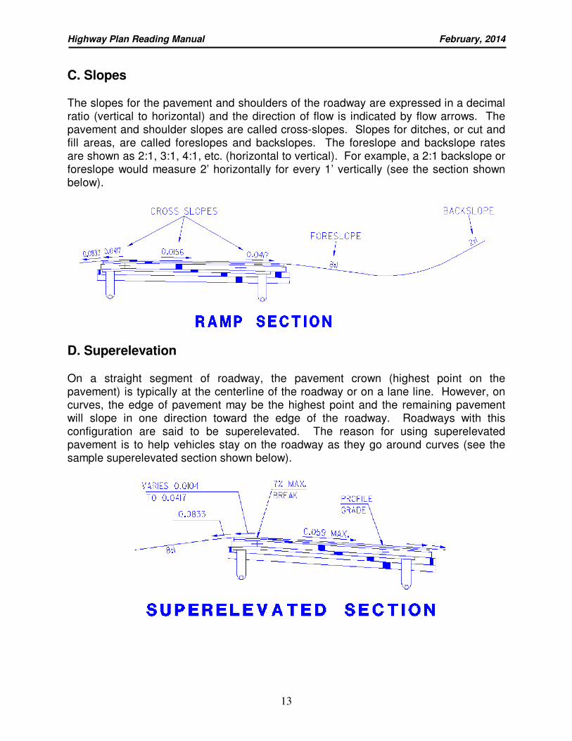
C. Slopes The slopes for the pavement and shoulders of the roadway are expressed in a decimal ratio (vertical to horizontal) and the direction of flow is indicated by flow arrows. The pavement and shoulder slopes are called cross-slopes. Slopes for ditches, or cut and fill areas, are called foreslopes and backslopes. The foreslope and backslope rates are shown as 2:1, 3:1, 4:1, etc. (horizontal to vertical). For example, a 2:1 backslope or foreslope would measure 2’ horizontally for every 1’ vertically (see the section shown below).
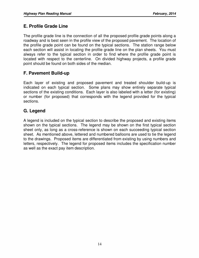
D. Superelevation On a straight segment of roadway, the pavement crown (highest point on the pavement) is typically at the centerline of the roadway or on a lane line. However, on curves, the edge of pavement may be the highest point and the remaining pavement will slope in one direction toward the edge of the roadway. Roadways with this configuration are said to be superelevated. The reason for using superelevated pavement is to help vehicles stay on the roadway as they go around curves (see the sample superelevated section shown below).
Highway Plan Reading Manual February, 2014
14
E. Profile Grade Line The profile grade line is the connection of all the proposed profile grade points along a roadway and is best seen in the profile view of the proposed pavement. The location of the profile grade point can be found on the typical sections. The station range below each section will assist in locating the profile grade line on the plan sheets. You must always refer to the typical section in order to find where the profile grade point is located with respect to the centerline. On divided highway projects, a profile grade point should be found on both sides of the median.
F. Pavement Build-up Each layer of existing and proposed pavement and treated shoulder build-up is indicated on each typical section. Some plans may show entirely separate typical sections of the existing conditions. Each layer is also labeled with a letter (for existing) or number (for proposed) that corresponds with the legend provided for the typical sections.
G. Legend A legend is included on the typical section to describe the proposed and existing items shown on the typical sections. The legend may be shown on the first typical section sheet only, as long as a cross-reference is shown on each succeeding typical section sheet. As mentioned above, lettered and numbered balloons are used to tie the legend to the drawings. Proposed items are differentiated from existing by using numbers and letters, respectively. The legend for proposed items includes the specification number as well as the exact pay item description.
Highway Plan Reading Manual February, 2014
15
QUIZ 2
Using the WAR-48-21.05 Typical Section sheets, answer the following: 1. What is the cross-slope of the proposed pavement on Typical Section 2? _________
2. (a) What is the width of the Graded Shoulder on the left side of Typical Section 4?
____________________
(b) What is the maximum paved shoulder width? ________________
3. What does balloon “10” refer to on Typical Section 4? ________________________
4. What is the maximum superelevation rate shown on the Typical Sections? ________
5. What thickness and type of material will be used for the surface course (top course)
of the proposed roadway and paved shoulders on Typical Section 1?
__________________________________________________________________
_
6. What is the maximum back slope permitted at station 1115+50 Rt.?_____________
7. Which Typical Sections show the placement of Item 844 - Class HP Concrete,
Bridge Deck (Parapet)? _________________________________
8. What is the distance required for rounding at the bottom of the ditch? ___________
9. What are the limiting stations for Typical Section 6?
__________________________________________________________________
_
10. Where is the Profile Grade located on the Typical Sections?
___________________________________________________________________
Highway Plan Reading Manual February, 2014
16
5. GENERAL NOTES
The general notes shown on a roadway plan contain those plan notes required to clarify construction items that are not satisfactorily covered by the specifications or plan details and cannot be shown graphically (i.e. “As Per Plan” items may have a plan note explaining the deviation(s) from the standard item). The general notes include information regarding the administration and procedure of the work as opposed to specific construction details. They are unique for each project. Unless otherwise stated, the general notes will take precedence over other general provisions (such as the Construction and Material Specifications) which would normally apply to the project.
6. MAINTENANCE OF TRAFFIC PLANS
The maintenance of traffic plans tell the contractor how traffic will be maintained while construction is being performed. When through traffic is detoured during the entire construction period, the detour route is shown on either the title sheet, location map, schematic plan, within the general notes, or on its own sheet. If the detour is shown somewhere other than the title sheet location map, it is referenced in the index of sheets. When traffic is maintained during construction, the plan will normally require a number of maintenance of traffic notes along with several details such as sequence of operations, section details for maintaining traffic, plan insert sheets, crossover details, temporary barrier details, etc.
7. GENERAL SUMMARY
The general summary sheets list the quantities of all the materials that are used to construct the highway project. It is also a summary of the quantities calculated on each subsequent plan sheet. The quantities are presented in such a manner that they may be traced to their origin by using a system of cross-references. These quantities are totaled on the general summary sheet and are used by the State in preparing its engineering estimate and by the contractors in preparing their bids. The location of “As Per Plan” and “Special” item details should be cross-referenced in the “See Sheet No.” column in the General Summary.
8. PROJECT SITE PLAN The Project Site Plan is included on projects having 1 or more acres of earth disturbing activities or projects classified as maintenance that have earth disturbing activities exceeding 5 acres. The project site plan is an overview of the project area similar in appearance to the schematic plan discussed earlier in this manual. The construction contractor uses this plan to prepare a Storm Water Pollution Prevention Plan (SWPPP) meeting Ohio EPA and NPDES (National Pollutant Discharge Elimination System) requirements.
Highway Plan Reading Manual February, 2014
17
QUIZ 3
Using the WAR-48-21.05 General Notes, Maintenance of Traffic, and General Summary sheets, answer the following:
1. Between what stations is Rock and/or Shale excavation expected to be necessary?
__________________________________________________________________
_
2. What plan sheet identifies details about Item 604-Catch Basin, No. 3, APP(As Per
Plan)? _____________
3. What plan sheet shows the location of monuments? __________
4. How many trees, 15" in diameter or larger, are being removed? __________
5. Is there a designated local detour for this project? __________
6 Which State Routes are being used for the official detour route?________________
7. (a) How much Item-410 Traffic Compacted Surface, APP is provided? ___________
(b) What makes this Item of work As Per Plan? _____________________________
__________________________________________________________________
_
8. (a) How much Item 606-Guardrail, Type 5 is being used on the project? __________
(b) What sheet(s) carry quantities to the Gen. Summary for this item? ___________
9. (a) How much Item 602-Concrete Masonry, APP is being used on the project?
_____________
(b) What plan sheet(s) provide additional information on the placement of this Item?
____________
10. What plan sheet contains the estimated quantities for Structure WAR-48-2102? ___
Highway Plan Reading Manual February, 2014
18
9. PLAN AND PROFILE SHEETS Plan and profile sheets depict the existing area and also show what the proposed area will resemble after the roadway construction is completed. In addition, they show quantities, dimensions, and other miscellaneous items that are required to layout and construct the project.
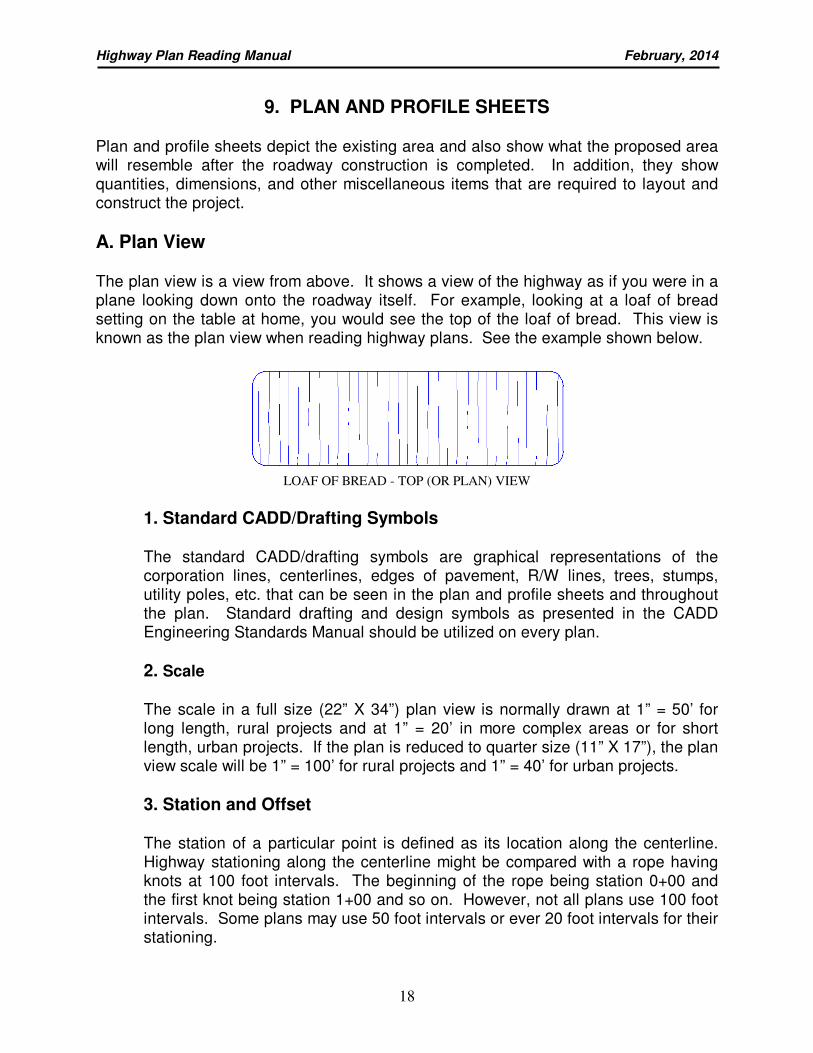
A. Plan View The plan view is a view from above. It shows a view of the highway as if you were in a plane looking down onto the roadway itself. For example, looking at a loaf of bread setting on the table at home, you would see the top of the loaf of bread. This view is known as the plan view when reading highway plans. See the example shown below.
LOAF OF BREAD - TOP (OR PLAN) VIEW
1. Standard CADD/Drafting Symbols
The standard CADD/drafting symbols are graphical representations of the corporation lines, centerlines, edges of pavement, R/W lines, trees, stumps, utility poles, etc. that can be seen in the plan and profile sheets and throughout the plan. Standard drafting and design symbols as presented in the CADD Engineering Standards Manual should be utilized on every plan.
2. Scale
The scale in a full size (22” X 34”) plan view is normally drawn at 1” = 50’ for long length, rural projects and at 1” = 20’ in more complex areas or for short length, urban projects. If the plan is reduced to quarter size (11” X 17”), the plan view scale will be 1” = 100’ for rural projects and 1” = 40’ for urban projects.
3. Station and Offset
The station of a particular point is defined as its location along the centerline. Highway stationing along the centerline might be compared with a rope having knots at 100 foot intervals. The beginning of the rope being station 0+00 and the first knot being station 1+00 and so on. However, not all plans use 100 foot intervals. Some plans may use 50 foot intervals or ever 20 foot intervals for their stationing.
Highway Plan Reading Manual February, 2014
19
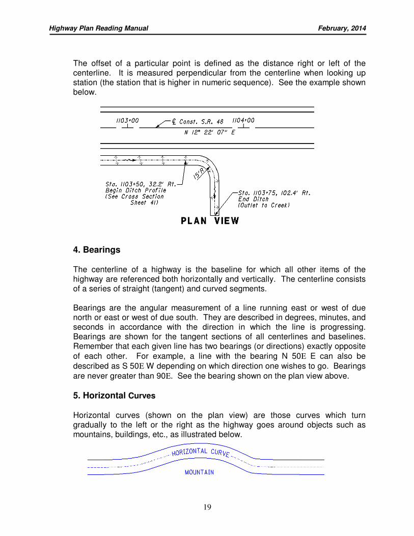
The offset of a particular point is defined as the distance right or left of the centerline. It is measured perpendicular from the centerline when looking up station (the station that is higher in numeric sequence). See the example shown below.
4. Bearings
The centerline of a highway is the baseline for which all other items of the highway are referenced both horizontally and vertically. The centerline consists of a series of straight (tangent) and curved segments. Bearings are the angular measurement of a line running east or west of due north or east or west of due south. They are described in degrees, minutes, and seconds in accordance with the direction in which the line is progressing. Bearings are shown for the tangent sections of all centerlines and baselines. Remember that each given line has two bearings (or directions) exactly opposite
of each other. For example, a line with the bearing N 50Ε E can also be
described as S 50Ε W depending on which direction one wishes to go. Bearings
are never greater than 90Ε. See the bearing shown on the plan view above.
5. Horizontal Curves
Horizontal curves (shown on the plan view) are those curves which turn gradually to the left or the right as the highway goes around objects such as mountains, buildings, etc., as illustrated below.
Highway Plan Reading Manual February, 2014
20
Horizontal curve data for simple curves is shown on the plan view. Horizontal curve data for spiral curves (where the curve radius is not constant) may only show the P.I. station, delta and degree of curve on the plan and profile sheet if the entire curve data has been shown on the schematic plan.
6. Items of Work
All existing features of the topography are shown on the plan and profile sheet. The disposition of all such items within the existing and/or proposed right of way is indicated as well as all proposed features. Existing features, except buildings, are shown using dashed lines. Proposed features are shown with solid dark lines. Some of the items that you will consistently see on plans are bridges, edges of pavement, curbs, shoulders, drives, guardrails, trees and stumps, streams, creeks, ponds, lakes, utility poles, property lines, right of way lines, drainage items, construction limits and government boundaries.
The balloons containing numbers and letters that are shown on the plan and profile sheets are called reference balloons. The designations within the balloons correspond to the reference designation in the estimated quantities box. The reference designation is usually a combination of letters and numbers that indicates the general description of the item and differentiates them between similar items. For example, a UD or U is used to denote underdrain, a GR or G is used to denote guardrail, a D is used to denote drainage, etc. D-1, D-2 and D-3 are be used when there are three drainage items all appearing on the same plan and profile sheet.
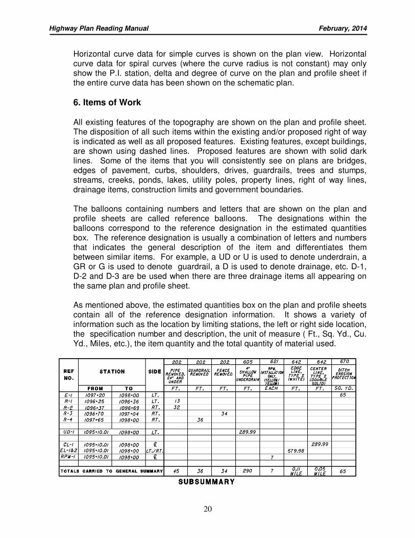
As mentioned above, the estimated quantities box on the plan and profile sheets contain all of the reference designation information. It shows a variety of information such as the location by limiting stations, the left or right side location, the specification number and description, the unit of measure ( Ft., Sq. Yd., Cu. Yd., Miles, etc.), the item quantity and the total quantity of material used.
Highway Plan Reading Manual February, 2014
21
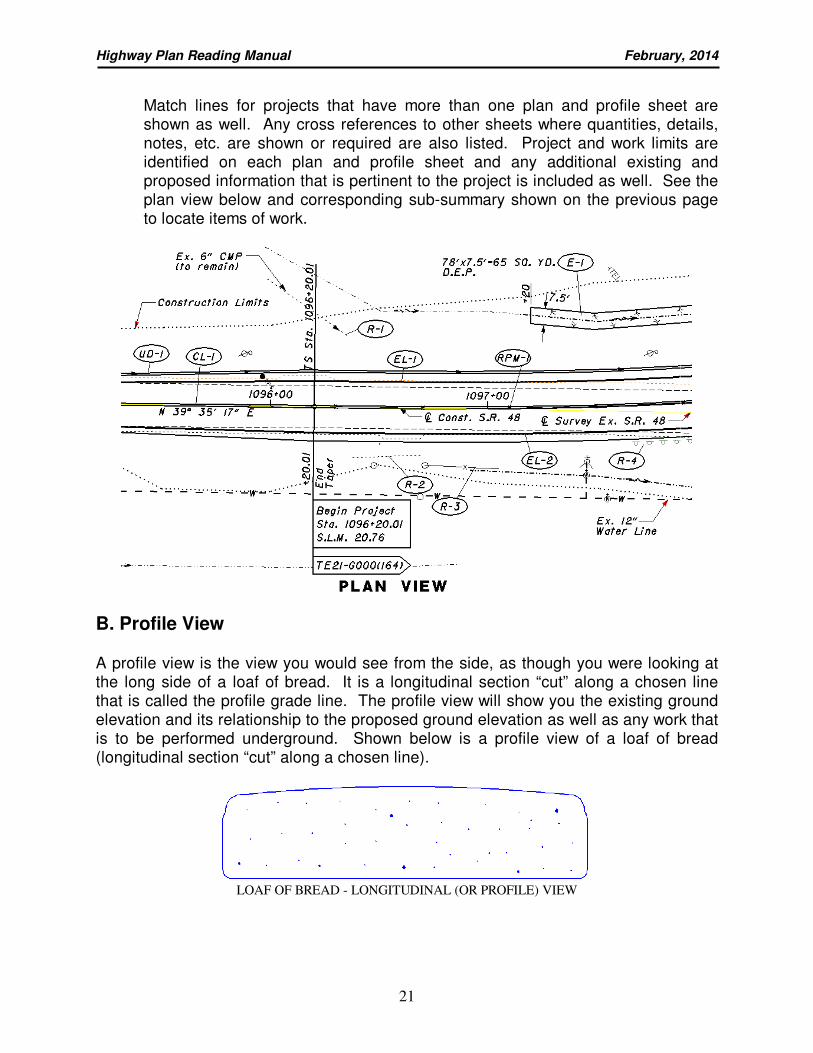
Match lines for projects that have more than one plan and profile sheet are shown as well. Any cross references to other sheets where quantities, details, notes, etc. are shown or required are also listed. Project and work limits are identified on each plan and profile sheet and any additional existing and proposed information that is pertinent to the project is included as well. See the plan view below and corresponding sub-summary shown on the previous page to locate items of work.
B. Profile View A profile view is the view you would see from the side, as though you were looking at the long side of a loaf of bread. It is a longitudinal section “cut” along a chosen line that is called the profile grade line. The profile view will show you the existing ground elevation and its relationship to the proposed ground elevation as well as any work that is to be performed underground. Shown below is a profile view of a loaf of bread (longitudinal section “cut” along a chosen line).
LOAF OF BREAD - LONGITUDINAL (OR PROFILE) VIEW
Highway Plan Reading Manual February, 2014
22
1. Scale
The horizontal scale in the profile view is the same as that of the horizontal scale in the plan view. The vertical scale is usually 1”=5’ or 1” =10’ for a full size (22” X 34”) plan sheet. If the plan is reduced 50% (11"x 17"), the scale for the profile view would be 1” = 10’ or 1” = 20’. Since the profile view uses a grid system, elevations can be found and measurements can be taken in ways other than by measuring with a scale. Each large square on the full size profile view grid represents 20’ horizontally, but only 5’ vertically. Similarly for the reduced sheets, the profile view grid represents 40’ horizontally and 10’ vertically.
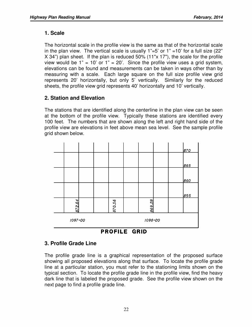
2. Station and Elevation
The stations that are identified along the centerline in the plan view can be seen at the bottom of the profile view. Typically these stations are identified every 100 feet. The numbers that are shown along the left and right hand side of the profile view are elevations in feet above mean sea level. See the sample profile grid shown below.
3. Profile Grade Line
The profile grade line is a graphical representation of the proposed surface showing all proposed elevations along that surface. To locate the profile grade line at a particular station, you must refer to the stationing limits shown on the typical section. To locate the profile grade line in the profile view, find the heavy dark line that is labeled the proposed grade. See the profile view shown on the next page to find a profile grade line.
Highway Plan Reading Manual February, 2014
23
4. Slopes and Grades
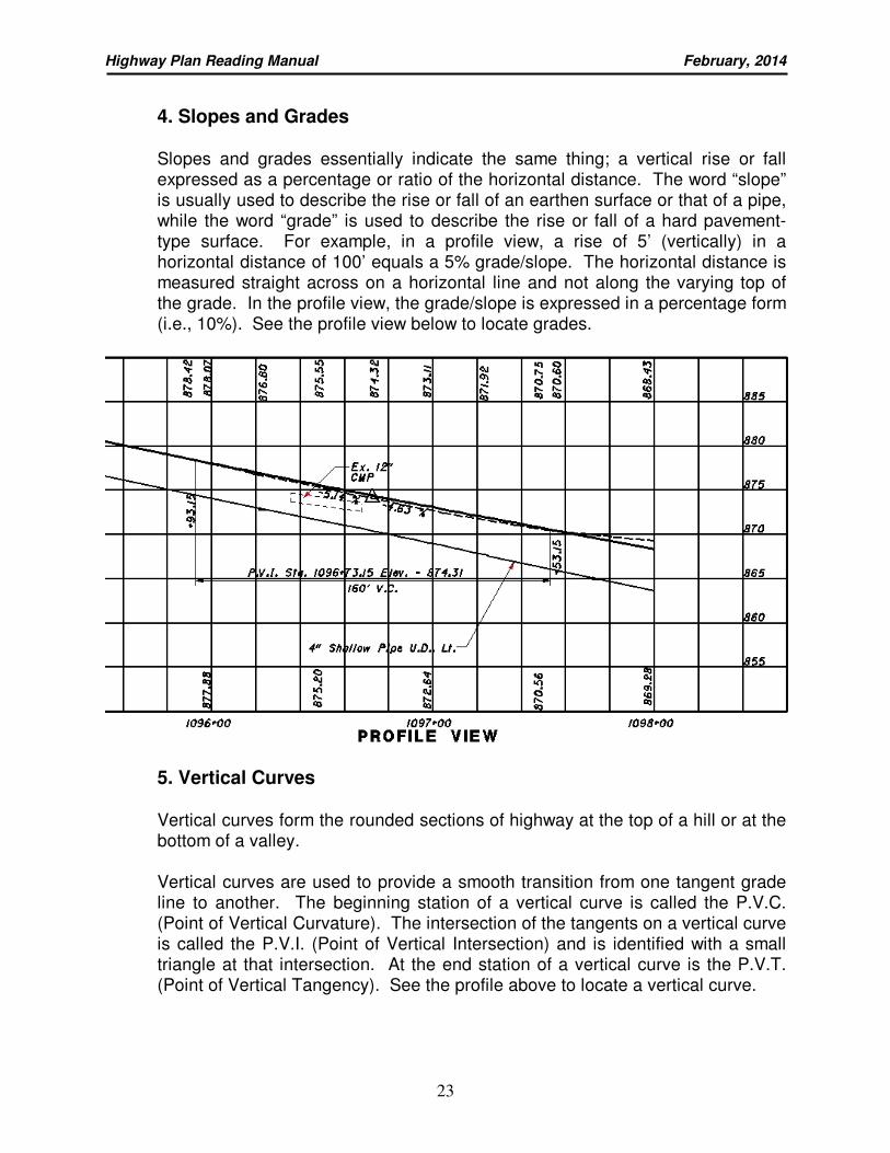
Slopes and grades essentially indicate the same thing; a vertical rise or fall expressed as a percentage or ratio of the horizontal distance. The word “slope” is usually used to describe the rise or fall of an earthen surface or that of a pipe, while the word “grade” is used to describe the rise or fall of a hard pavement-type surface. For example, in a profile view, a rise of 5’ (vertically) in a horizontal distance of 100’ equals a 5% grade/slope. The horizontal distance is measured straight across on a horizontal line and not along the varying top of the grade. In the profile view, the grade/slope is expressed in a percentage form (i.e., 10%). See the profile view below to locate grades.
5. Vertical Curves
Vertical curves form the rounded sections of highway at the top of a hill or at the bottom of a valley.
Vertical curves are used to provide a smooth transition from one tangent grade line to another. The beginning station of a vertical curve is called the P.V.C. (Point of Vertical Curvature). The intersection of the tangents on a vertical curve is called the P.V.I. (Point of Vertical Intersection) and is identified with a small triangle at that intersection. At the end station of a vertical curve is the P.V.T. (Point of Vertical Tangency). See the profile above to locate a vertical curve.
Highway Plan Reading Manual February, 2014
24
6. Drainage and Utilities
In the profile view, information will be shown regarding the roadway drainage. Underdrains, field drains and any other type of drainage items needed to complete the project are shown. In addition, major structures such as bridges and culvert pipes and any underground utility information are shown here. See the profile view above for underdrain information.
QUIZ 4 Using the WAR-48-21.05 Plan and Profile sheets, answer the following: 1. At the beginning of the project does the existing roadway slope upward or
downward (heading up station)? _______________
2. What percentage of slope does the proposed roadway have at station 1100+00?
_______________
3. (a) What is the existing grade elevation at station1101+00? ________________
(b) What is the proposed grade elevation at station1101+00? _______________
4. What quantity of Shallow Pipe Underdrain is used on sheet 29? _____________
5. (a) Balloon “D -1" on sheet 30 refers to how many Items of work? ____________
(b) What are these Item(s) of work? ___________________________________
________________________________________________________________
6. (a) What is the width of Item 670-Ditch Erosion Protection placed on sheet 30 to
the right of the centerline of construction?_______________
(b) What is the maximum distance right of the centerline of construction that this
item will be placed at station 1103+75? _______________
7. Where are the totals from the subsummary on sheet 30 carried? ____________
________________________________________________________________
8. What Drainage Item is being placed at station 1109+00 Rt.?
_______________________________________________________________
9. How much guardrail is being removed on sheet 31? ______________________
10. How wide is the existing driveway at station 1115+03.55 Rt.?________________
Highway Plan Reading Manual February, 2014
25
10. CROSS SECTIONS
A cross sectional view is the view you would see if you were looking at the front (short side) of a loaf of bread and pulled the first three slices away. The next piece of bread that you would see would be considered a cross section of the loaf of bread. See the example below.
SLICE OF BREAD - CROSS SECTION
The main purpose for using cross sections is to show end areas and surface dimensions for the calculation of earthwork and seeding quantities. They also show a wealth of additional information that will be discussed in the following paragraphs.
A. Scales Cross sections sheets are usually plotted to a scale of 1” = 5’ or 1” = 10’, both horizontally and vertically. The elevations are labeled along each side of the sheet at 1” intervals. If the sheet is reduced 50%, the scales become 1” = 10’ or 1” = 20’.
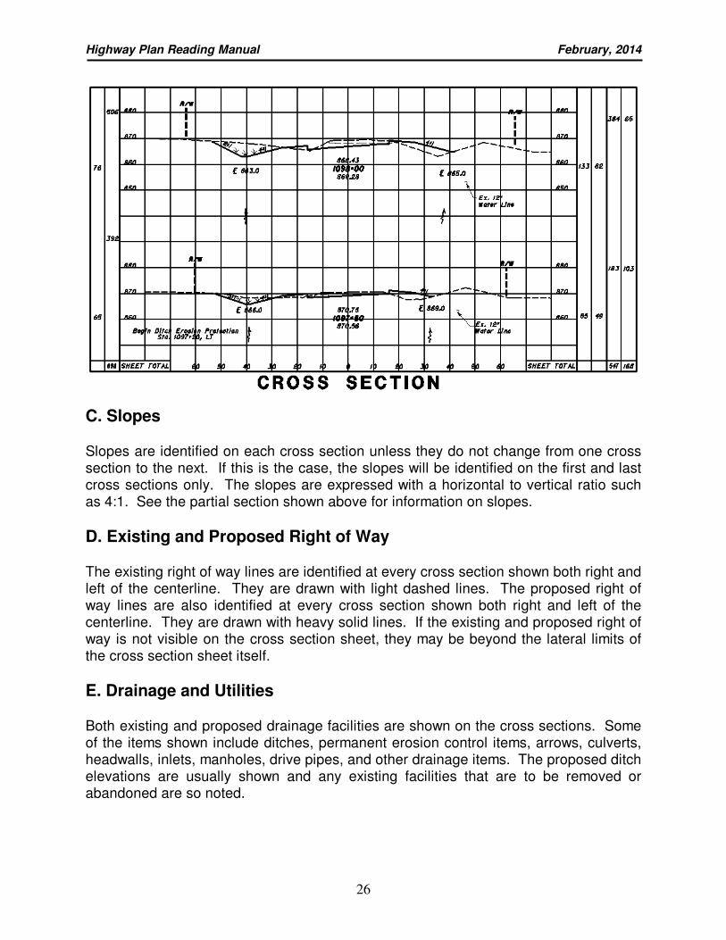
B. Station and Offset Each cross section is “cut” at a certain station along the centerline and that station is shown below the cross section itself. Also shown are the existing elevation and the proposed elevation of the profile grade point at that station. The spacing between cross sections may vary from 25’ to a maximum of 100’ depending on the project type and the terrain involved. The offset distance, shown both left and right of the centerline, is labeled at the top and bottom of each cross section sheet. See the partial section shown on the next page for station and offset information.
Highway Plan Reading Manual February, 2014
26
C. Slopes Slopes are identified on each cross section unless they do not change from one cross section to the next. If this is the case, the slopes will be identified on the first and last cross sections only. The slopes are expressed with a horizontal to vertical ratio such as 4:1. See the partial section shown above for information on slopes.
D. Existing and Proposed Right of Way The existing right of way lines are identified at every cross section shown both right and left of the centerline. They are drawn with light dashed lines. The proposed right of way lines are also identified at every cross section shown both right and left of the centerline. They are drawn with heavy solid lines. If the existing and proposed right of way is not visible on the cross section sheet, they may be beyond the lateral limits of the cross section sheet itself.
E. Drainage and Utilities Both existing and proposed drainage facilities are shown on the cross sections. Some of the items shown include ditches, permanent erosion control items, arrows, culverts, headwalls, inlets, manholes, drive pipes, and other drainage items. The proposed ditch elevations are usually shown and any existing facilities that are to be removed or abandoned are so noted.
Highway Plan Reading Manual February, 2014
27
All existing and proposed underground utilities are shown on the cross sections. Some of the items shown include telephone lines, gas lines, sanitary sewer lines, TV cable lines, and other utility items. Existing utilities to be removed or abandoned are so noted. See the partial section shown on the previous page for drainage information.
F. Seeding and Earthwork Seeding quantities show the areas that will be seeded after the project is complete. End widths and seeding areas are shown in the columns on the left side of the cross section sheet. The seeding width that is calculated for each individual cross section is known as the end width and is calculated in feet. The seeding area is then calculated by multiplying the average of two end widths by the distance between the cross sections and is shown in square yards. Earthwork is the removal (cut) or addition (fill) of dirt or rock that is needed to complete the project. End areas and earthwork volumes are shown for cuts and fills in columns on the right side of the cross section sheet. The cut and fill areas that are calculated for each cross section is called the end area. The end areas are calculated in square feet. Earthwork volumes are the cut and fill areas between cross sections or the area calculated from one station to the next station. The earthwork volumes are calculated in cubic yards. See the partial section shown on the previous page for seeding and earthwork quantities.
G. Partial Sections Partial sections are used when important information is located between cross sections or when information is located too far to the right or left of the section and does not fit on the cross section sheet. These sections are inserted between the regular cross sections.
Highway Plan Reading Manual February, 2014
28
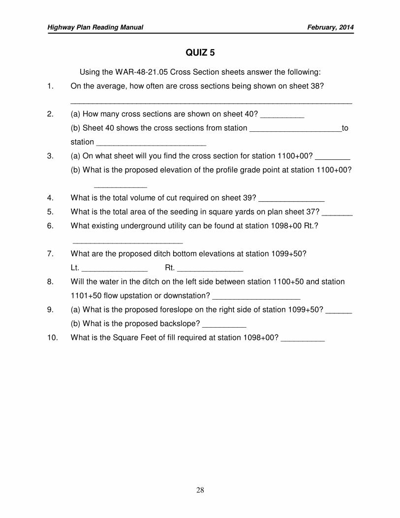
QUIZ 5
Using the WAR-48-21.05 Cross Section sheets answer the following:
1. On the average, how often are cross sections being shown on sheet 38?
________________________________________________________________
2. (a) How many cross sections are shown on sheet 40? __________
(b) Sheet 40 shows the cross sections from station _____________________to
station _________________________
3. (a) On what sheet will you find the cross section for station 1100+00? ________
(b) What is the proposed elevation of the profile grade point at station 1100+00?
____________
4. What is the total volume of cut required on sheet 39? _______________
5. What is the total area of the seeding in square yards on plan sheet 37? _______
6. What existing underground utility can be found at station 1098+00 Rt.?
_________________________
7. What are the proposed ditch bottom elevations at station 1099+50?
Lt. _______________ Rt. _______________
8. Will the water in the ditch on the left side between station 1100+50 and station
1101+50 flow upstation or downstation? ____________________
9. (a) What is the proposed foreslope on the right side of station 1099+50? ______
(b) What is the proposed backslope? __________
10. What is the Square Feet of fill required at station 1098+00? __________
Highway Plan Reading Manual February, 2014
29
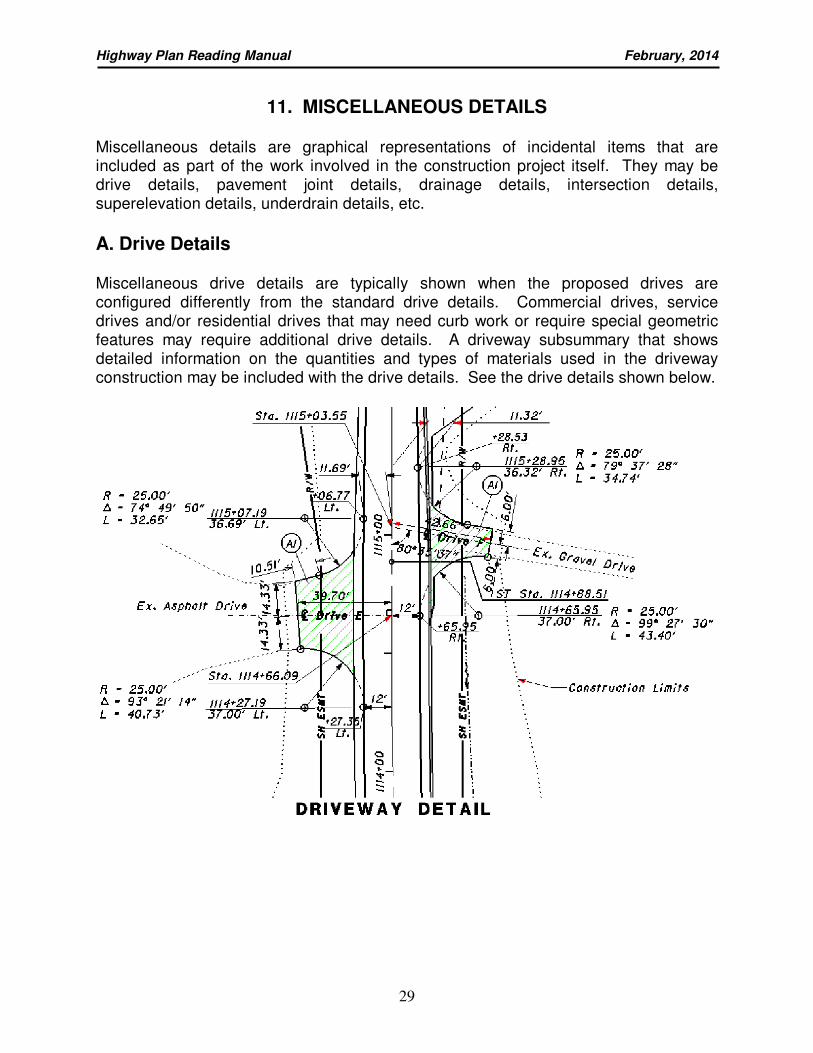
11. MISCELLANEOUS DETAILS
Miscellaneous details are graphical representations of incidental items that are included as part of the work involved in the construction project itself. They may be drive details, pavement joint details, drainage details, intersection details, superelevation details, underdrain details, etc.
A. Drive Details
Miscellaneous drive details are typically shown when the proposed drives are configured differently from the standard drive details. Commercial drives, service drives and/or residential drives that may need curb work or require special geometric features may require additional drive details. A driveway subsummary that shows detailed information on the quantities and types of materials used in the driveway construction may be included with the drive details. See the drive details shown below.
Highway Plan Reading Manual February, 2014
30
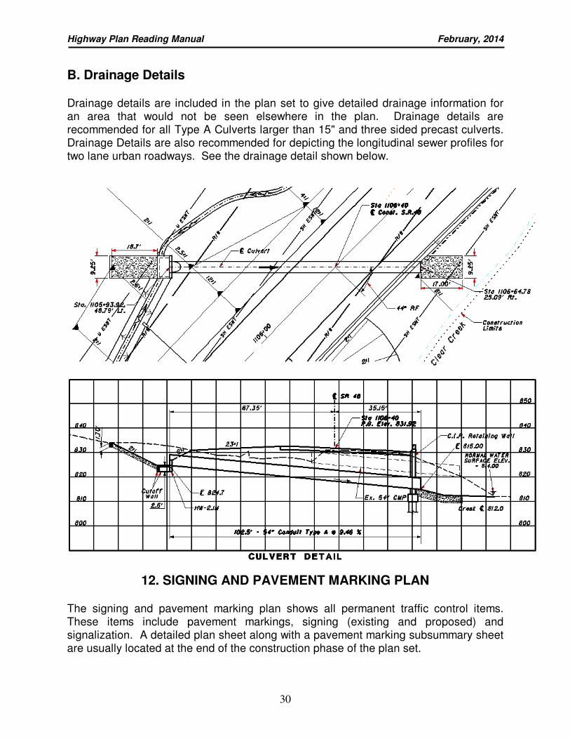
B. Drainage Details
Drainage details are included in the plan set to give detailed drainage information for an area that would not be seen elsewhere in the plan. Drainage details are recommended for all Type A Culverts larger than 15" and three sided precast culverts. Drainage Details are also recommended for depicting the longitudinal sewer profiles for two lane urban roadways. See the drainage detail shown below.
12. SIGNING AND PAVEMENT MARKING PLAN
The signing and pavement marking plan shows all permanent traffic control items. These items include pavement markings, signing (existing and proposed) and signalization. A detailed plan sheet along with a pavement marking subsummary sheet are usually located at the end of the construction phase of the plan set.
Highway Plan Reading Manual February, 2014
31
PART II: RIGHT OF WAY PLANS
The right of way plans are an integral part of a standard set of highway plans, however, not all construction plans will contain an associated set of right of way plans. Only those construction projects that require the purchase of additional right of way in order to complete the work will have right of way plans in the plan set. Similar to construction plans, right of way plans are developed by various design professionals. ODOT uses both in-house designers and outside consultants to prepare right of way plans. A registered surveyor is required to sign the legend sheet and centerline plat sheet, “if one is to be included in the plan”. Right of way plans provide numerous users with detailed, technical information in order to perform the appraisal and acquisition of rights of way. They show the required takes, the information needed to acquire the land and also serve as documentation of ODOT’s right of way. Appraisers utilize the right of way plans to establish fair market value by determining all items of value to be taken and their effect on the value of any remaining residual. Negotiators utilize the right of way plans to explain to the individual property owners exactly what changes are being made to their particular properties. Relocation agents utilize the right of way plans to determine whether there will be a displacement of persons on a particular project. Usually every set of right of way plans contains certain standard information that provides insight into the particular phases of the right of way acquisition process. Each project may have its own unique features and, as such, may require special additions, such as a utility plan, a railroad plat, etc., be added to the right of way plan. Other conditions, such as minimal takes areas or low fair market or unit value, may dictate the use of an alternate right of way plan format instead of the traditional right of way plan format. Most right of way plans contain a legend sheet, centerline plat sheet(s), property map sheet(s), summary of additional right of way sheet(s) and right of way detail sheet(s). Additionally some right of way plans will contain a utility plan sheet and/or schematic plan sheet. The information provided in this manual will help to acquaint you with the different sections that are developed and assembled to form a right of way plan and will assist you in interpreting the right of way details presented.
1. LEGEND SHEET
A. Index of Sheets
The index serves as a table of contents for the right of way plan. When a sheet is added after the Right of Way Tracing are submitted or just before, sheets may be inserted into the plan by alphabetizing (Example: current sheet = 10, new sheets = 10A, 10B, etc.) All alphabetized sheets must be shown in the index of sheets.
Highway Plan Reading Manual February, 2014
32
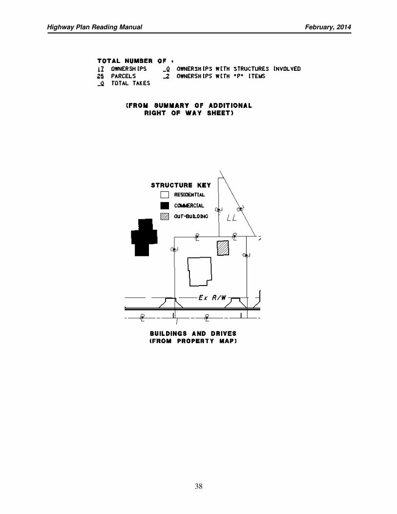
B. Structure Key
A structure key is provided to illustrate whether the buildings are residential, commercial or out buildings.
C. Utility Easements, List and Note
When a separate utility plan is not required, significant utility easements and all corresponding utility data are shown on the property map. The list will show the particular office that will serve as a contact for the project and will include the name, address and phone number of all affected utilities. There will also be an underground utility note describing how the utility information was obtained in order to plot the underground utilities shown.
D. Conventional Symbols Commonly used symbols and line styles throughout the right of way plans are displayed here. It is the responsibility of the Right of Way Plan Designer to update the Conventional Symbols for each set of plans prepared.
E. Project Description The project description is a brief paragraph describing the primary purpose of the improvement and shows the project length. The project length is the total distance between the beginning and ending project points. This description should mirror the project description listed on the title sheet of the construction plans.
D. Plans Prepared By Provides the name of the firm that designed the plans, the name of the right of way plan designer and the right of way plan reviewer and the date in which the right of way plans were competed. The completion date is the date the design agency has complied with all review comments and submitted the plans as the Right of Way Tracings. The individual that performs the field review shall provide their signature and the date in which the review was performed. The designer shall sign and date the day they completed updating the ownership information which must be within 15 working days of submitting the Right of Way Tracings.
Highway Plan Reading Manual February, 2014
33
E. Survey Certification The survey certification is a statement required on the legend sheet and centerline plat. The certification statement identifies the surveyor(s) name, registration number, and the surveyor’s signature and seal. The surveyor is required to provide a brief description of what is being certified and indicate that he/she either personally performed the work or supervised its completion.
F. Parcel Identifier Legend
The Parcel Identifier Legend denotes the abbreviation for each parcel identifier used in the plan, and presents the full name of each abbreviation.
2. CENTERLINE PLAT
The centerline plat sheet or sheets is a plat of the centerline of a project and serves two major purposes. The first is to define the proposed centerline and relate it precisely to its geographical and boundary-related location. The second is to show the exact location of new monuments that are set in order to maintain the physical location of the centerline. The centerline plat is filed in the county recorder’s office in the county where the project is located.
A. Local Orientation
The local orientation describes exactly where the project is located. At the top of the centerline plat, the county, route and section information is shown, followed by the original public land survey, city, village, civil township and county in which the projected is located. The township, range and survey section data should be shown with the local orientation. See the local orientation data shown below.
WAR-48-21.05
SECTION 35 & 36
TOWNSHIP 4 EAST RANGE 4 NORTH
CLEAR CREEK TOWNSHIP
WARREN COUNTY
Highway Plan Reading Manual February, 2014
34
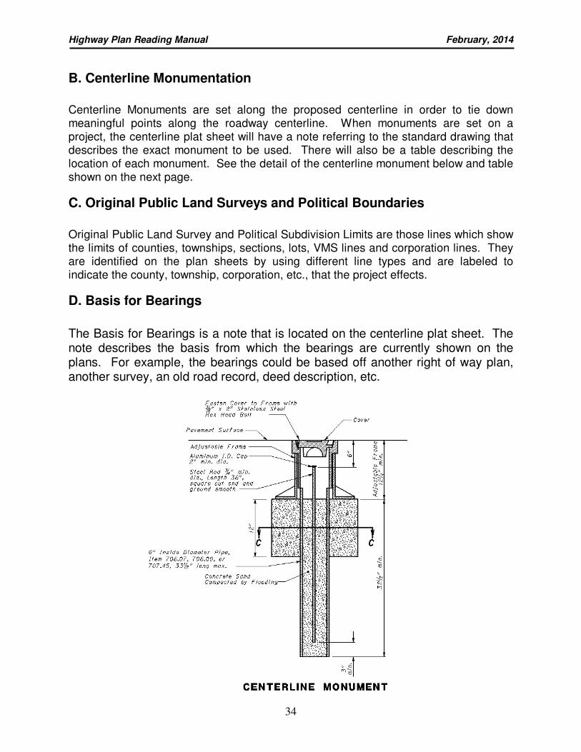
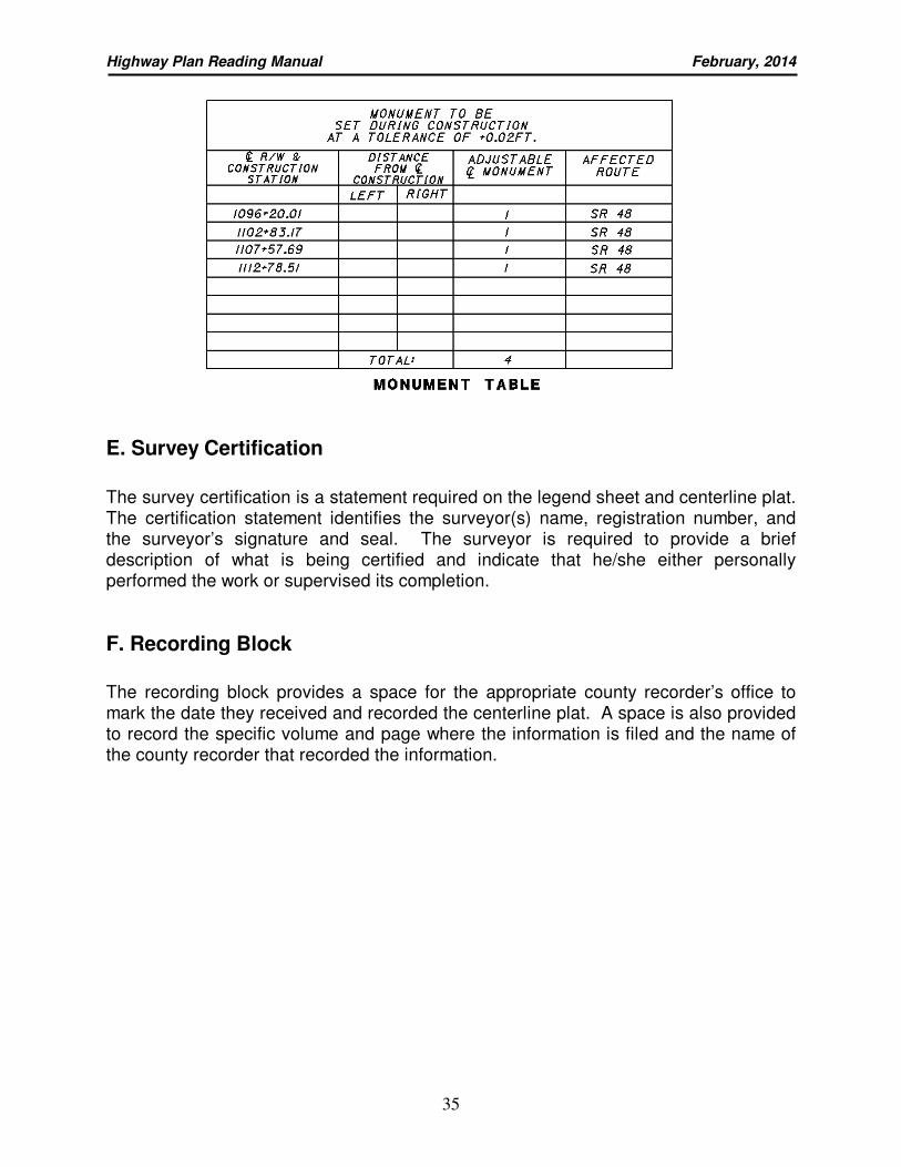
B. Centerline Monumentation
Centerline Monuments are set along the proposed centerline in order to tie down meaningful points along the roadway centerline. When monuments are set on a project, the centerline plat sheet will have a note referring to the standard drawing that describes the exact monument to be used. There will also be a table describing the location of each monument. See the detail of the centerline monument below and table shown on the next page.
C. Original Public Land Surveys and Political Boundaries
Original Public Land Survey and Political Subdivision Limits are those lines which show the limits of counties, townships, sections, lots, VMS lines and corporation lines. They are identified on the plan sheets by using different line types and are labeled to indicate the county, township, corporation, etc., that the project effects.
D. Basis for Bearings
The Basis for Bearings is a note that is located on the centerline plat sheet. The note describes the basis from which the bearings are currently shown on the plans. For example, the bearings could be based off another right of way plan, another survey, an old road record, deed description, etc.
Highway Plan Reading Manual February, 2014
35
E. Survey Certification
The survey certification is a statement required on the legend sheet and centerline plat. The certification statement identifies the surveyor(s) name, registration number, and the surveyor’s signature and seal. The surveyor is required to provide a brief description of what is being certified and indicate that he/she either personally performed the work or supervised its completion.
F. Recording Block
The recording block provides a space for the appropriate county recorder’s office to mark the date they received and recorded the centerline plat. A space is also provided to record the specific volume and page where the information is filed and the name of the county recorder that recorded the information.
Highway Plan Reading Manual February, 2014
36
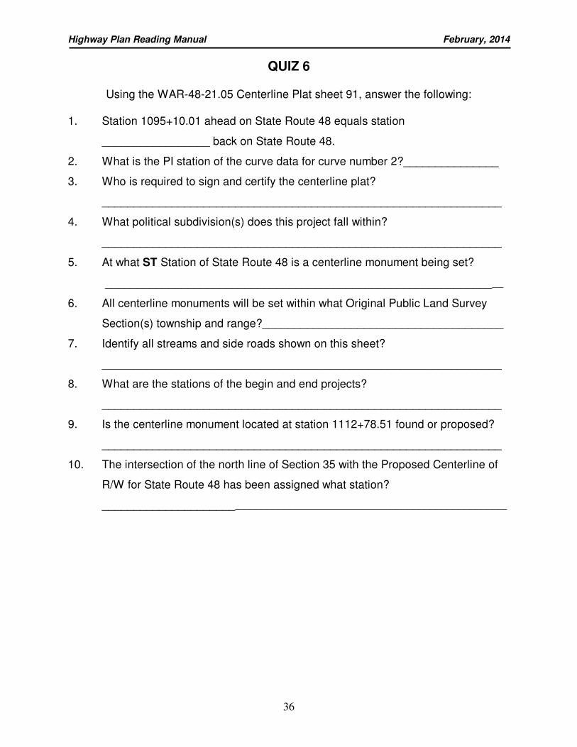
QUIZ 6
Using the WAR-48-21.05 Centerline Plat sheet 91, answer the following: 1. Station 1095+10.01 ahead on State Route 48 equals station
_________________ back on State Route 48.
2. What is the PI station of the curve data for curve number 2?_______________
3. Who is required to sign and certify the centerline plat?
_______________________________________________________________
4. What political subdivision(s) does this project fall within?
_______________________________________________________________
5. At what ST Station of State Route 48 is a centerline monument being set?
_______________________________________________________________
6. All centerline monuments will be set within what Original Public Land Survey
Section(s) township and range?______________________________________
7. Identify all streams and side roads shown on this sheet?
_______________________________________________________________
8. What are the stations of the begin and end projects?
_______________________________________________________________
9. Is the centerline monument located at station 1112+78.51 found or proposed?
_______________________________________________________________
10. The intersection of the north line of Section 35 with the Proposed Centerline of
R/W for State Route 48 has been assigned what station?
_____________________________________________________________________

Highway Plan Reading Manual February, 2014
37
3. PROPERTY MAP
The property map is a representation of the current auditor’s tax map on which the proposed highway right of way has been superimposed. The primary purpose of the property map is to present a good overall picture of the right of way requirements and show the relationship of the proposed right of way to each entire ownership of the project. The property map shows the property ownership lines, the approved alignment, the general limits of the right of way required and the residual lands on either side of the highway facility.
A. Ownership Name and Number
The owner’s name appears in every ownership area shown on the property map. If space is restricted and the name cannot be placed on the property itself, the property will be identified by using a number shown within the property that is referenced to a list of property owners located on the same plan sheet.
B. Property Lines
Property lines are drawn to show the end of one property and the beginning of the next property. All properties involved in the project will have their property lines shown on the sheet and will be clearly labeled.
C. Original Public Land Surveys and Political Boundaries
A boundary is something that marks or fixes a limit. Original public land surveys and political boundaries that mark counties, townships, sections, lots, VMS or corporation boundaries are labeled and drawn according to the information shown in the Conventional Signs or Standard CADD/Drafting symbols.
D. Buildings, Structures and Drives
The location of all buildings, structures and drives on the properties are shown and clearly identified. A structure key is provided on the Legend Sheet to illustrate whether the buildings are residential, commercial or out buildings and whether the buildings and/or drives are to remain or are to be removed. See the example shown on the next page.
Highway Plan Reading Manual February, 2014
38
Highway Plan Reading Manual February, 2014
39
E. Limit Flags
Three types of limit flags are typically shown on the property map. The first type of limit flags are used to show the “begin project” and “end project” locations. They are determined by the construction plans. The second type of limit flags are used to show the “begin work” and “end work” locations. These are also determined by the construction plans. The “begin work” and “end work” limits are the limits within which we must be concerned with encroachments. The third type of limit flags are used to show the “begin acquisition” and “end acquisition” locations. These are determined by locating the stations that are opposite the extreme points of new right of way, either permanent or temporary, that is required for the project.
F. Service Roads
Service roads may be provided for those property owners that have either landlocked property as a result of the construction or that may have had direct access to the road prior to the new construction project.
G. Landlocked Parcels or Residues
Landlocked parcels and residues are those pieces of land that have no roadway access. Landlocked parcels or residues are marked on the plan sheet as “LL” (or landlocked areas) and are also known as “E” parcels. See the drawing on the previous page for an example of a landlocked parcel.
4. UTILITY PLAN SHEET
The need for a separate utility plan will depend largely on the nature, complexity of a project, the number of utilities affected and their involvement. If a separate utility plan is not required, all utility ownership information shall be shown on both the general notes of the construction plan and property map of the right of way plans. While detailed information is shown on plan and profile sheets of the construction plans and right of way detail sheets of the right of way plans. For additional information refer to sections 8100 and 8200 of the Real Estates Policies and Procedures Manual.
Highway Plan Reading Manual February, 2014
40
QUIZ 7
Using the WAR-48-21.05 Property Map sheet 92, answer the following:
1. Is there an easement that crosses parcels 8, 9 and 10? yes_____/no_____
If so, what is the recording information and what is it for?
_______________________________ ______________________________
recording information purpose
2. Who is the utility contact for cable tv?
________________________________________________________________
3. What is the symbol for a utility telecommunications pole?
_______________________________________________________________
4. CountryTyme, Inc. owns a parcel of land located near the southern portion of the
project. What auditor’s parcel number does it have?
________________________________________________________________
5. At what station does right of way acquisition begin on State Route 48?
________________________________________________________________
6. Identify a parcel of land that is landlocked on this project ?
_______________________________________________________________
7. Common ownership of contiguous parcels will be indicated by the symbol?
___________ (sometimes called a landhook)
8. Will the proposed right of way surrounding the project be LA-R/W or R/W?
_______________________________________________________________
9. Does the proposed centerline of R/W for route 48 cross clear creek?
_______________________________________________________________
If so, at about what station does this occur?
_______________________________________________________________
10. Who is the owner of the parcel designated by the balloon ∈?
_______________________________________________________________
Highway Plan Reading Manual February, 2014
41
5. SUMMARY OF ADDITIONAL RIGHT OF WAY
The summary of additional right of way sheet is a tabular listing of all parcels affected by the project. It summarizes the types of taking and all other aspects of the particular land areas involved in the acquisition.
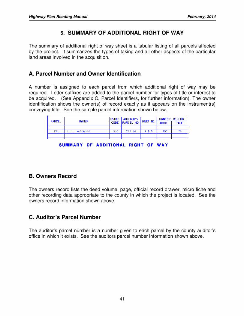
A. Parcel Number and Owner Identification
A number is assigned to each parcel from which additional right of way may be required. Letter suffixes are added to the parcel number for types of title or interest to be acquired. (See Appendix C, Parcel Identifiers, for further information). The owner identification shows the owner(s) of record exactly as it appears on the instrument(s) conveying title. See the sample parcel information shown below.
B. Owners Record
The owners record lists the deed volume, page, official record drawer, micro fiche and other recording data appropriate to the county in which the project is located. See the owners record information shown above.
C. Auditor’s Parcel Number
The auditor’s parcel number is a number given to each parcel by the county auditor’s office in which it exists. See the auditors parcel number information shown above.
Highway Plan Reading Manual February, 2014
42
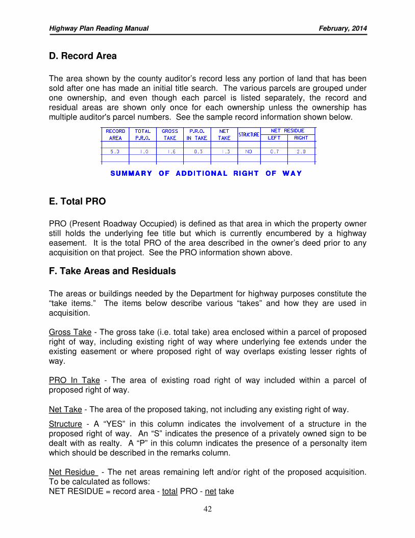
D. Record Area
The area shown by the county auditor’s record less any portion of land that has been sold after one has made an initial title search. The various parcels are grouped under one ownership, and even though each parcel is listed separately, the record and residual areas are shown only once for each ownership unless the ownership has multiple auditor's parcel numbers. See the sample record information shown below.
E. Total PRO
PRO (Present Roadway Occupied) is defined as that area in which the property owner still holds the underlying fee title but which is currently encumbered by a highway easement. It is the total PRO of the area described in the owner’s deed prior to any acquisition on that project. See the PRO information shown above.
F. Take Areas and Residuals
The areas or buildings needed by the Department for highway purposes constitute the “take items.” The items below describe various “takes” and how they are used in acquisition. Gross Take - The gross take (i.e. total take) area enclosed within a parcel of proposed right of way, including existing right of way where underlying fee extends under the existing easement or where proposed right of way overlaps existing lesser rights of way. PRO In Take - The area of existing road right of way included within a parcel of proposed right of way.
Net Take - The area of the proposed taking, not including any existing right of way.
Structure - A “YES” in this column indicates the involvement of a structure in the proposed right of way. An “S” indicates the presence of a privately owned sign to be dealt with as realty. A “P” in this column indicates the presence of a personalty item which should be described in the remarks column. Net Residue - The net areas remaining left and/or right of the proposed acquisition. To be calculated as follows: NET RESIDUE = record area - total PRO - net take
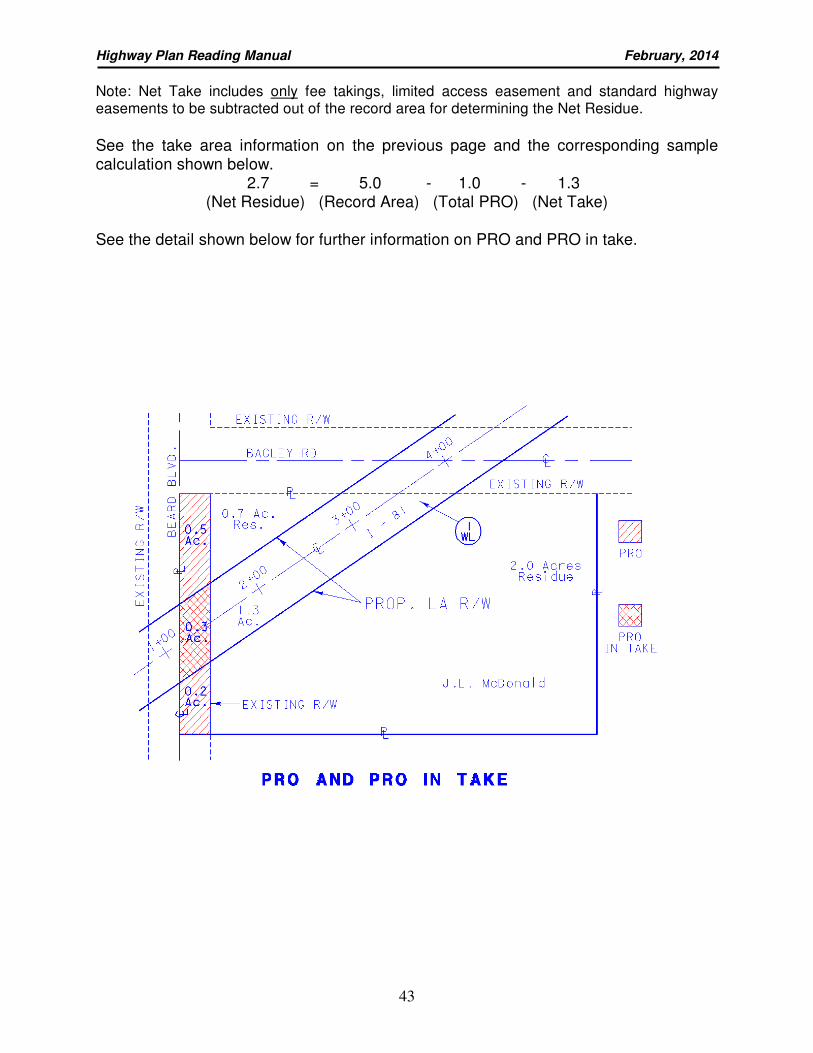
Highway Plan Reading Manual February, 2014
43
Note: Net Take includes only fee takings, limited access easement and standard highway easements to be subtracted out of the record area for determining the Net Residue.
See the take area information on the previous page and the corresponding sample calculation shown below.
2.7 = 5.0 - 1.0 - 1.3 (Net Residue) (Record Area) (Total PRO) (Net Take)
See the detail shown below for further information on PRO and PRO in take.
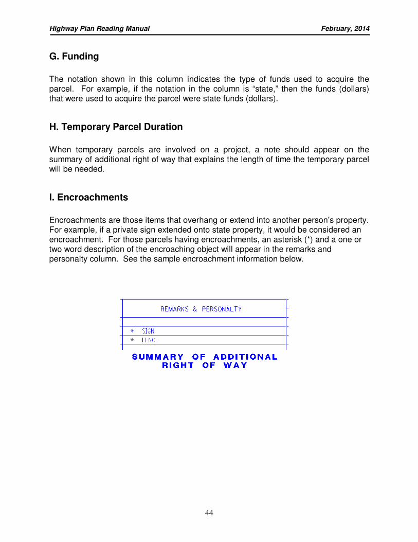
Highway Plan Reading Manual February, 2014
44
G. Funding
The notation shown in this column indicates the type of funds used to acquire the parcel. For example, if the notation in the column is “state,” then the funds (dollars) that were used to acquire the parcel were state funds (dollars).
H. Temporary Parcel Duration
When temporary parcels are involved on a project, a note should appear on the summary of additional right of way that explains the length of time the temporary parcel will be needed.
I. Encroachments
Encroachments are those items that overhang or extend into another person’s property. For example, if a private sign extended onto state property, it would be considered an encroachment. For those parcels having encroachments, an asterisk (*) and a one or two word description of the encroaching object will appear in the remarks and personalty column. See the sample encroachment information below.
Highway Plan Reading Manual February, 2014
45
QUIZ 8
Using the WAR-48-21.05 Summary of Additional R/W sheet 94, answer the following:
1. What type of take does the symbol “WD” stand for? _______ (See Appendix C)
(a) fee simple reservation of access (b) fee simple for mineral rights (c) fee simple with limitation of access (d) none of the above
2. What type of take does the symbol “SL” stand for? _______ (See Appendix C)
(a) channel easement (b) slope easement (c) warranty deed for land acquired in excess of that needed for right of way (d) none of the above
3. What is the “Gross Take” of parcel 15-T?
_______________________________________________________________
4. Who is the owner of parcel 12-WD?
_______________________________________________________________
5. Does parcel 14-WD have residue? yes_____/no_____
If so, what is the net residue of this parcel? _____________________________
6. On what plan sheet page(s) would you find detailed information regarding parcel
16-WD? _________________________
7. What type of funding is the right of way being purchased with?______________
8. Identify the last revision made on Plan Sheet 94/101 and the date it was made?
_______________________________________________________________
9. What is the “Net take” for parcel 11-WD?
_______________________________________________________________
10. How many different auditor's parcel numbers does parcel 11 have ?
_______________________________________________________________
(a) What are they?
_______________________________________________________________
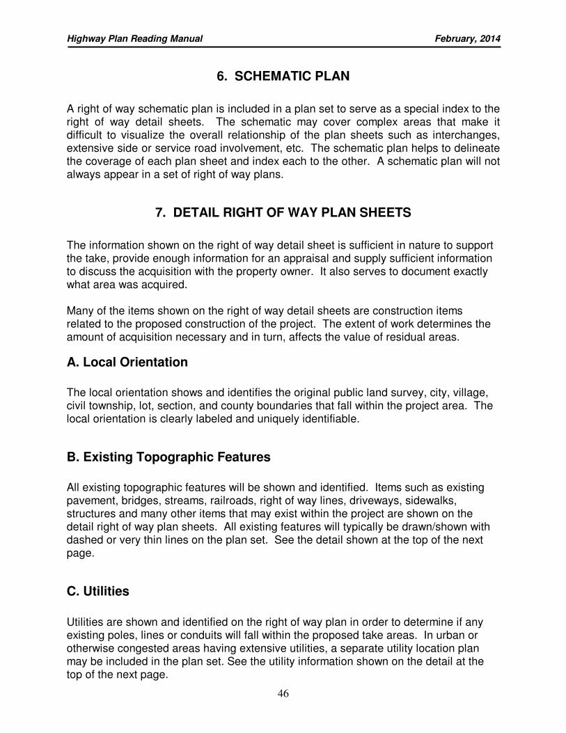
Highway Plan Reading Manual February, 2014
46
6. SCHEMATIC PLAN
A right of way schematic plan is included in a plan set to serve as a special index to the right of way detail sheets. The schematic may cover complex areas that make it difficult to visualize the overall relationship of the plan sheets such as interchanges, extensive side or service road involvement, etc. The schematic plan helps to delineate the coverage of each plan sheet and index each to the other. A schematic plan will not always appear in a set of right of way plans.
7. DETAIL RIGHT OF WAY PLAN SHEETS
The information shown on the right of way detail sheet is sufficient in nature to support the take, provide enough information for an appraisal and supply sufficient information to discuss the acquisition with the property owner. It also serves to document exactly what area was acquired. Many of the items shown on the right of way detail sheets are construction items related to the proposed construction of the project. The extent of work determines the amount of acquisition necessary and in turn, affects the value of residual areas.
A. Local Orientation
The local orientation shows and identifies the original public land survey, city, village, civil township, lot, section, and county boundaries that fall within the project area. The local orientation is clearly labeled and uniquely identifiable.
B. Existing Topographic Features
All existing topographic features will be shown and identified. Items such as existing pavement, bridges, streams, railroads, right of way lines, driveways, sidewalks, structures and many other items that may exist within the project are shown on the detail right of way plan sheets. All existing features will typically be drawn/shown with dashed or very thin lines on the plan set. See the detail shown at the top of the next page.
C. Utilities
Utilities are shown and identified on the right of way plan in order to determine if any existing poles, lines or conduits will fall within the proposed take areas. In urban or otherwise congested areas having extensive utilities, a separate utility location plan may be included in the plan set. See the utility information shown on the detail at the top of the next page.
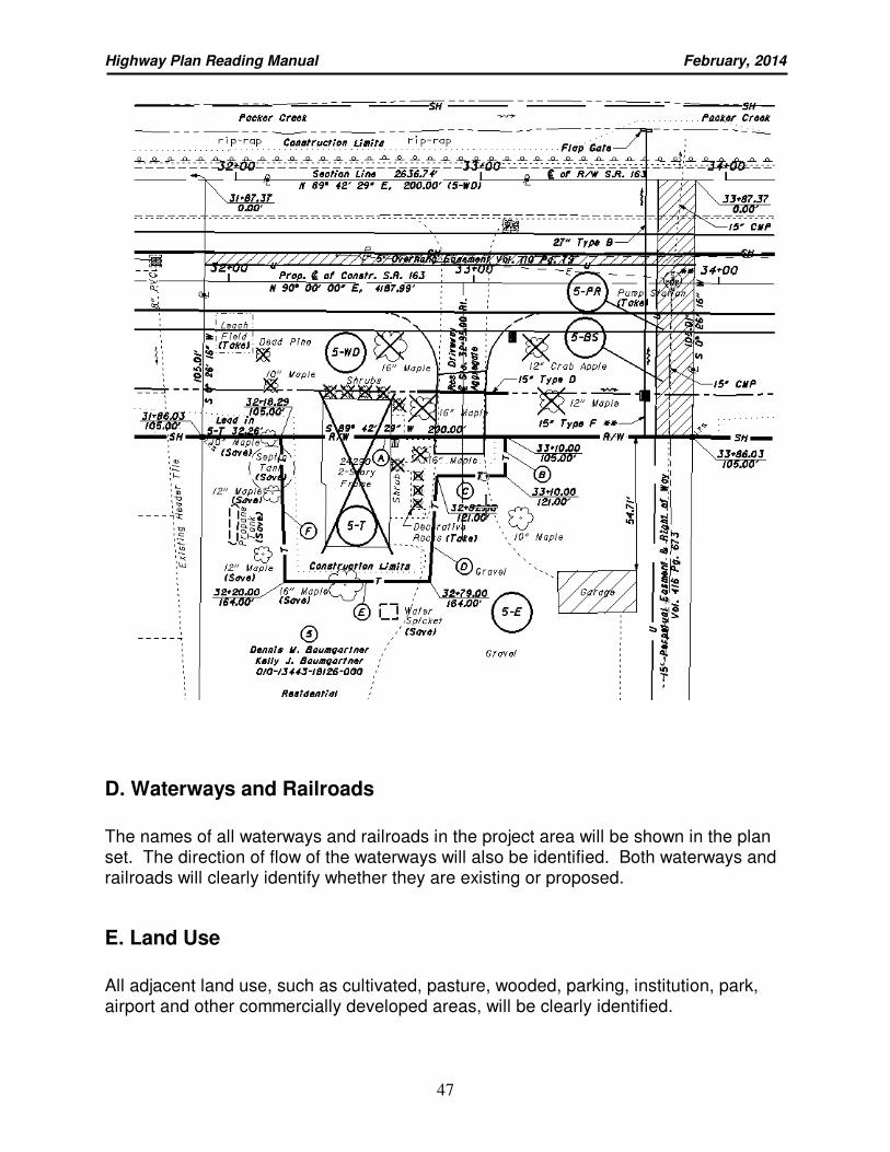
Highway Plan Reading Manual February, 2014
47
D. Waterways and Railroads
The names of all waterways and railroads in the project area will be shown in the plan set. The direction of flow of the waterways will also be identified. Both waterways and railroads will clearly identify whether they are existing or proposed.
E. Land Use
All adjacent land use, such as cultivated, pasture, wooded, parking, institution, park, airport and other commercially developed areas, will be clearly identified.
Highway Plan Reading Manual February, 2014
48
G. Property Lines
Property lines within the project area will be shown and clearly labeled on all plan sheets.
Highway Plan Reading Manual February, 2014
49
H. Survey Data
Survey data provides the information needed to create centerlines for all roadways, railroads, property lines, streams and waterways. This information consists of stationing, bearings, distances and curve data such as PI’s, PT’s, PC’s, etc. The curve data will be shown at least once per sheet for every curve that appears on that sheet.
I. Right of Way Limits
Proposed right of way lines will be shown as the darkest and heaviest lines on the right of way plan sheets and labeled as such. Straight segments of the right of way lines will show bearing and distances. Curved segments will show the radius, chord bearing, chord distance and arc length for each curve. The information will be shown on each sheet that the curve appears. Where iron pins are set on the new right of way line, they will be shown with the appropriate standard symbol. See the detail shown on the previous page for existing and proposed right of way limits.
J. Station and Offset
Where an angle, break, intersection, easement and/or property lines intersect the proposed right of way lines, a station and offset call will be placed. Station and offset labels will also be shown on all iron pins, pipes and survey monuments that are found as well as when cross references switch from one centerline to another. See the detail on the previous page for station and offset information.
K. Parcel Balloons
Parcel balloons are those balloons that appear on the detail right of way plan sheet and show an ownership number and parcel identifier in them. The parcel number that appears in the balloon is carried to the parcel number column on the summary of additional right of way sheet for reference purposes. See the detail on the previous page for parcel balloon information.
L. Items of Work
All proposed items of work are shown including the disposition of all such items within the existing and proposed right of way. Proposed items of work are shown with solid darker lines as compared to the existing items present. Some of the items of work that are consistently shown on the plans are driveways, drainage structures, sewers, edges of pavement, curbs and gutters, shoulders, trees and stumps, streams, creeks, ponds, lakes, utility poles, etc. See the detail shown on the previous page for items of work.
Highway Plan Reading Manual February, 2014
50
M. Right of Way Fence
All proposed and existing right of way fence will be shown on the plan. Woven wire fence Type 47 is usually placed two (2) feet inside the proposed right of way line and chain link fence is usually placed one (1) foot inside the proposed right of way line.
N. Construction Limits
The construction limits are shown as short dashed lines. They start at the beginning of construction and show both longitudinal and lateral work limits until the end of construction. See the detail shown on page 47 for the construction limits.
Highway Plan Reading Manual February, 2014
51
QUIZ 9
Using the WAR-48-21.05 Right of Way Plan sheets 95-101 to answer the following:
1. What type of general land use exists on parcel 6?
_______________________________________________________________
2. Sheet 95 was last revised when and for what reason?
________________________________________________________________
3. What was found 36.72 feet left of station 1103+69.26?
_______________________________________________________________
4. What is the size of the existing plastic pipe (to be removed) that crosses parcels
3-WD and 7-
WD?__________________________________________________
5. Who owns parcels 3A?
________________________________________________________________
6. Examine and explain the purpose/need for the Temporary of parcel 3?
________________________________________________________________
________________________________________________________________
7. What recording information declared the existing right of way width be 60'?
________________________________________________________________
________________________________________________________________
8. Several pine trees on parcel 14 will be removed during construction. What are
the sizes of these trees?
_______________________________________________________________
________________________________________________________________
9. What are the different types of R/W takes shown on plan sheet 96/101?
________________________________________________________________
10. Identify the name of the subdivision located west of S.R. 48 and list which lot
numbers within that subdivision will be affected by this project?
________________________________________________________________
________________________________________________________________
Highway Plan Reading Manual February, 2014
52
APPENDIXES
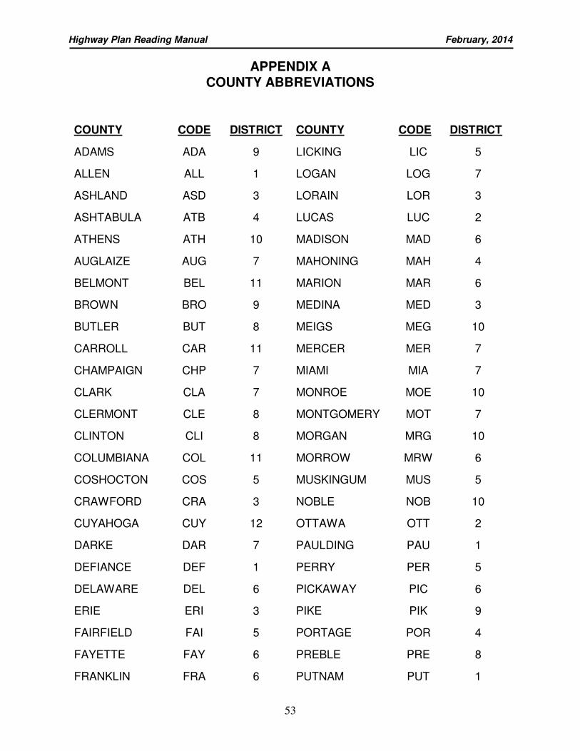
Highway Plan Reading Manual February, 2014
53
APPENDIX A COUNTY ABBREVIATIONS
COUNTY CODE DISTRICT COUNTY CODE DISTRICT
ADAMS ADA 9 LICKING LIC 5
ALLEN ALL 1 LOGAN LOG 7
ASHLAND ASD 3 LORAIN LOR 3
ASHTABULA ATB 4 LUCAS LUC 2
ATHENS ATH 10 MADISON MAD 6
AUGLAIZE AUG 7 MAHONING MAH 4
BELMONT BEL 11 MARION MAR 6
BROWN BRO 9 MEDINA MED 3
BUTLER BUT 8 MEIGS MEG 10
CARROLL CAR 11 MERCER MER 7
CHAMPAIGN CHP 7 MIAMI MIA 7
CLARK CLA 7 MONROE MOE 10
CLERMONT CLE 8 MONTGOMERY MOT 7
CLINTON CLI 8 MORGAN MRG 10
COLUMBIANA COL 11 MORROW MRW 6
COSHOCTON COS 5 MUSKINGUM MUS 5
CRAWFORD CRA 3 NOBLE NOB 10
CUYAHOGA CUY 12 OTTAWA OTT 2
DARKE DAR 7 PAULDING PAU 1
DEFIANCE DEF 1 PERRY PER 5
DELAWARE DEL 6 PICKAWAY PIC 6
ERIE ERI 3 PIKE PIK 9
FAIRFIELD FAI 5 PORTAGE POR 4
FAYETTE FAY 6 PREBLE PRE 8
FRANKLIN FRA 6 PUTNAM PUT 1
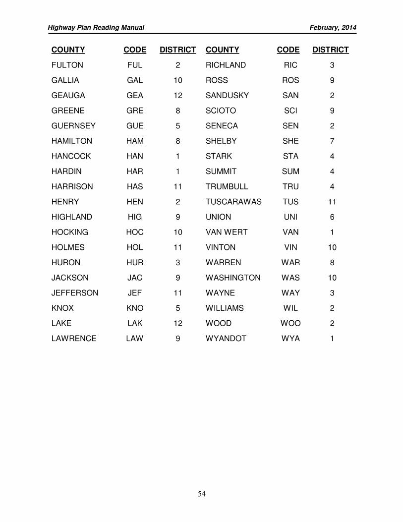
Highway Plan Reading Manual February, 2014
54
COUNTY CODE DISTRICT COUNTY CODE DISTRICT
FULTON FUL 2 RICHLAND RIC 3
GALLIA GAL 10 ROSS ROS 9
GEAUGA GEA 12 SANDUSKY SAN 2
GREENE GRE 8 SCIOTO SCI 9
GUERNSEY GUE 5 SENECA SEN 2
HAMILTON HAM 8 SHELBY SHE 7
HANCOCK HAN 1 STARK STA 4
HARDIN HAR 1 SUMMIT SUM 4
HARRISON HAS 11 TRUMBULL TRU 4
HENRY HEN 2 TUSCARAWAS TUS 11
HIGHLAND HIG 9 UNION UNI 6
HOCKING HOC 10 VAN WERT VAN 1
HOLMES HOL 11 VINTON VIN 10
HURON HUR 3 WARREN WAR 8
JACKSON JAC 9 WASHINGTON WAS 10
JEFFERSON JEF 11 WAYNE WAY 3
KNOX KNO 5 WILLIAMS WIL 2
LAKE LAK 12 WOOD WOO 2
LAWRENCE LAW 9 WYANDOT WYA 1
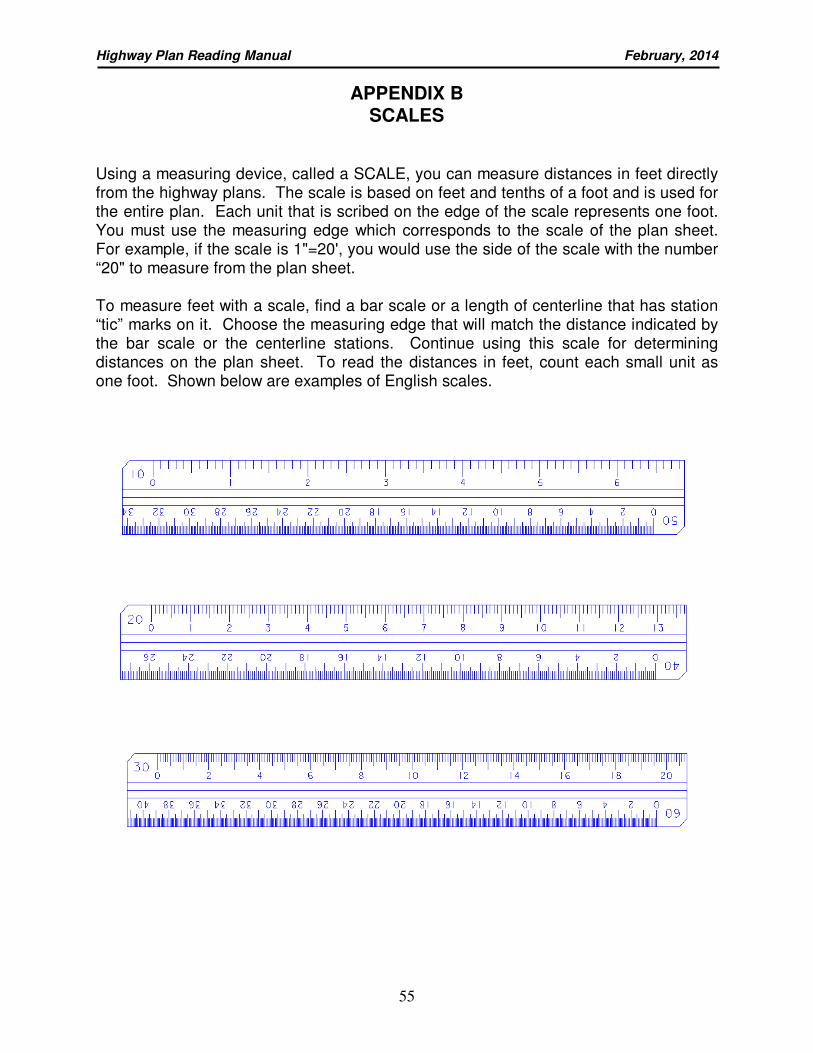
Highway Plan Reading Manual February, 2014
55
APPENDIX B SCALES
Using a measuring device, called a SCALE, you can measure distances in feet directly from the highway plans. The scale is based on feet and tenths of a foot and is used for the entire plan. Each unit that is scribed on the edge of the scale represents one foot. You must use the measuring edge which corresponds to the scale of the plan sheet. For example, if the scale is 1"=20', you would use the side of the scale with the number “20" to measure from the plan sheet. To measure feet with a scale, find a bar scale or a length of centerline that has station “tic” marks on it. Choose the measuring edge that will match the distance indicated by the bar scale or the centerline stations. Continue using this scale for determining distances on the plan sheet. To read the distances in feet, count each small unit as one foot. Shown below are examples of English scales.
Highway Plan Reading Manual February, 2014
56
PRACTICE IN USING THE SCALE
Using the English scale, try the questions shown below as a test of your skill in using the scale with the R/W plan sheets included with your course manual.
Using WAR-48-21.05 Right of Way Detail sheet 96, answer the following questions:
1. What is the approximate width of the proposed permanent R/W at station
1102+00?
________________________________________________________________
2. From the proposed centerline of right of way, what is the offset of the easterly
end of the 4" plastic pipe extending into parcel 7?
_______________________________
3. What is the approximate width of the construction limits at station 1101+00?
________________________________________________________________
4. The proposed centerline of right of way and construction for S.R. 48 has moved
how many feet from the existing centerline of S.R. 48 at station 1103+00?
________________________________________________________________
5. What is the distance from the existing westerly R/W line to the building setback
line at station 1099+50? ____________________________________________
Highway Plan Reading Manual February, 2014
57
APPENDIX C PARCEL IDENTIFIERS
The following are brief descriptions of various types of title to be acquired and their associated parcel identifiers. For detailed information on types of title to be acquired, see Section 3200 of the Office of Real Estate’s Policies and Procedures Manual.
Fee Simple Title
Fee simple title will be acquired for permanent rights of way on new location, limited access, and urban area facilities, except for aerial and footer easements on operating railroad rights of way and rights outside of the main right of way for drainage (channel, sewers, etc.). Fee simple title may also be acquired for any other type of project or for specific ownerships as beneficial to the Department.
Fee simple title is further classified by the intended use within the highway facility. The following parcel identifiers describe these classifications:
WL - Fee Simple With Limitation of Access
Use this identifier to acquire fee simple title for highway rights of way where a plan requires full limitation of access to the facility. The WL instrument may be for whole takes on fully limited access highways even though a portion of the taking lies outside the limited access boundary. The right of way plan will show the portion outside the boundary as a WD area if control of access is not needed.
The form presumes full limitation of access. When design requires less than full limitation of access, such as on a controlled access facility, a limiting feature may be inserted immediately following the description, for example, "Except 12 foot wide residential drive left from station 10+50 to station 10+62".
WD - Fee Simple Reservation of Access
Use this identifier to acquire fee simple title where limitation of access is not to be acquired. The WD form states that the grantor retains the right of ingress and egress to and from any residual area.
BS - Bill of Sale
Use this identifier for an agreement to acquire improvements on the land independent of the conveyance of title.
Highway Plan Reading Manual February, 2014
58
PRW - Property Right Fee Simple
Use this identifier for an agreement to compensate for the impairment of the right of ingress and egress, when such impairment is directly attributable to the proposed highway facility yet there is no physical acquisition of land. Use the “PRW” identifier when the associated highway right of way is owned in fee. In all cases where "PRW" is used, the Remark's Column of the Summary of Additional Right of Way Sheet shall briefly indicate the specific impairment being compensated for. When it is unclear as whether a “PRW” take is necessary contact the District Real Estate Administrator.
E - Fee Simple Excess Land
Use this identifier for excess property that at some future date will be considered for either acquisition as an EL or ER parcel, or disposed of by sale or exchange. The Summary of Additional Right of Way Sheet and Right of Way Detail Plan Sheet shall show any excess land as an “E” parcel until it is disposed of or acquired.
EL - Acquired Fee Simple Excess Land If ODOT acquires the fee simple of any excess land, except an uneconomic remnant, then the former “E” parcel will be re-identified as “EL”.
ER - Fee Simple Uneconomic Remnant
If ODOT acquires the fee simple of excess land considered to be an uneconomic remnant [i.e., “a parcel of real property in which the owner is left with an interest after the partial acquisition of the owner's property and which the head of the agency concerned has determined has little or no value or utility to the owner.” See Ohio Rev. Code Section 163.59(K)], then the former “E” parcel will be re-identified as “ER.”
ES - Excess Land Sold or “Swapped” [See Ohio Rev. Code Section
5501.34]
Once the Director has declared certain parcels to be excess land no longer needed for highway purposes, they may be sold (either directly to abutters or at auction, depending on its value), or “swapped” to an owner as part of the consideration for other property being acquired from that owner along the same highway corridor as the excess land.
Highway Plan Reading Manual February, 2014
59
Easements
Highway easements convey, in perpetuity, the right to construct and maintain a highway facility on the land of the fee holder. The owner retains the underlying fee. The following are the two types of highway easements identifiers.
SH - Standard Highway Easement
Use this identifier to acquire rights of way for a highway improvement where fee simple title is not required and limitation of access from adjoining land is not desired.
LA - Limited Access Easement
Use this identifier to acquire a permanent easement for highway rights of way where a plan requires full limitation of access to the facility. The form presumes full limitation of access. When design requires less than full limitation of access, such as, on a controlled access facility, a limiting feature may be inserted immediately following the description. For example, "Except 12 foot wide residential drive left from station 10+50 to station 10+62".
When the easement needs from one owner are partially limited access and partially non-limited access, the separate easement needs shall be acquired as separate parcels. The suffix LA is used for the limited access parcel and SH is used for the non-limited access parcel. The description of the LA parcel is put on an LA Easement Description Sheet and the non-limited access parcel is put on an Easement for Highway Purposes Description Sheet and both are combined into one instrument.
Non-highway easements convey rights associated with the highway facility. The owner retains the underlying fee and can continue to use the property, within limits. The following identifiers describe the various types and uses of non-highway easements.
T - Temporary Easement Use this identifier for a temporary easement for specific purposes, outside permanent rights of way. Because the duration of a temporary easement is essential for appraisal purposes, a temporary easement must always state its duration in months, starting from the date of entry by ODOT or its contractor and ending when the proposed work has been completed and accepted. Temporary easements are most often used to make adjoining terrain, normally maintained by the owner, conform to new construction. Other uses for temporary easements include temporary detours, construction working areas, temporary access roads, and channel work not requiring a channel easement. A temporary easement is not to be used for parking or for storage of materials or equipment. No structures can be erected within a temporary easement without the owner’s written agreement. Temporary Easements must be in the name of the agency administering the construction; therefore “TV” takes should be used sparingly.
Highway Plan Reading Manual February, 2014
60
SL - Slope Easement
Use this identifier to acquire a continuing right for the construction and maintenance of slopes until such time as the owner desires to remove or build on the slope, provided that the proper preservation of a highway will not be impaired by such removal or occupancy of the slopes.
S - Sewer Easement
Use this identifier to acquire the right to construct and maintain a sewer outside regular highway rights of way. If additional land is needed to construct the sewer, the right of way plan must clearly show and delineate this land as a temporary parcel.
CH - Channel Easement
Use this identifier to acquire the right to construct and maintain, a perpetual watercourse within the area described in the easement. The grantor retains the right to use the area for any other purpose provided that this use does not impair the proper functioning of the channel.
This type of easement is used for the construction of an open watercourse channel that falls outside of the regular highway rights of way. It may also be used for a large, open channel that parallels a highway to avoid a riparian right controversy.
FL - Flowage Easement Use this identifier to acquire the perpetual right to cause water to flow over a described area, such as, temporary impoundment of storm water upstream from a channel restriction.
U - Easement For a Railroad or Public Utility Use this identifier to acquire an easement in the name of a railroad or public utility owning similar facilities for the readjustment or relocation of its facility when fee simple title is not desired. The Summary of Additional Right of Way Sheet and Right of Way Detail Plan Sheet shall show by note name in which the easement will be acquired when this type of easement is needed. An agreement is required between the Department and the Grantee giving the Department authority to acquire the parcel in the name of the Grantee and stipulating that the Grantee accepts the parcel.
A - Aerial Easement
Use this identifier to acquire an aerial easement to construct and maintain an elevated facility. Acquisition of aerial easements is independent of other easement rights that may need to be acquired under the aerial easements. For example, standard highway easements footer easements or sewer easements may need to be acquired under an aerial easement. The area of overlap of easements is to be shown on an overlap table on the right of way plan sheets.
Highway Plan Reading Manual February, 2014
61
PRE - Property Right
Use this identifier for an agreement to compensate for the impairment of the right of ingress and egress, when such impairment is directly attributable to the proposed highway facility yet there is no physical acquisition of land. Use the “PRE” identifier when the associated highway right of way is owned in highway easement. In all cases where "PRE" is used, the Remark's Column of the Summary of Additional Right of Way Sheet shall briefly indicate the specific impairment being compensated for. When it is unclear as whether a “PRE” take is necessary contact the District Real Estate Administrator.
SC - Scenic Easement
Use this identifier to acquire the right to preserve the use and development of an area adjacent to the highway in a manner consistent with the nature and intent of the highway beautification program.
Additional Modifiers "V" and "R" designations are modifiers used to identify either which political authority will be the eventual owner of the appropriated land or which special rights are expressly reserved for the landowner respectively. When "V" and "R" are used in the same parcel the "V" should precede "R". These identifiers are not to be used with any designations identified in 3205 Agreements.
V - In The Name of Another State Agency, LPA, etc. Use this identifier when acquiring property rights in the name of an entity other than the Department, such as another State Agency, political subdivision, etc. The Summary of Additional Right of Way Sheet shall show the name in which the property rights will be acquired. An agreement is required between the Department and the Grantee giving the Department authority to acquire the parcel in the name of the Grantee and stipulating that the Grantee accepts the parcel.
R - Special Reservation Use this identifier where certain rights in the area to be acquired (other than direct access rights) are reserved for the owner. Reservation may include mineral rights (such as coal below a stated elevation), limited rights of access over or under limited access rights of way (such as access under a viaduct), or other reservation which is special in nature. In all cases where "R" is used, the Remarks Column of the Summary of Additional Right of Way Sheet shall indicate briefly the type of reservation, i.e., special access, mineral, etc.
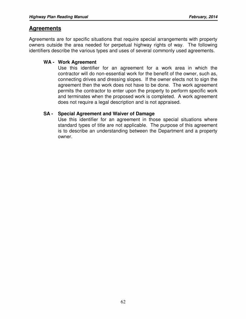
Highway Plan Reading Manual February, 2014
62
Agreements
Agreements are for specific situations that require special arrangements with property owners outside the area needed for perpetual highway rights of way. The following identifiers describe the various types and uses of several commonly used agreements.
WA - Work Agreement
Use this identifier for an agreement for a work area in which the contractor will do non-essential work for the benefit of the owner, such as, connecting drives and dressing slopes. If the owner elects not to sign the agreement then the work does not have to be done. The work agreement permits the contractor to enter upon the property to perform specific work and terminates when the proposed work is completed. A work agreement does not require a legal description and is not appraised.
SA - Special Agreement and Waiver of Damage Use this identifier for an agreement in those special situations where standard types of title are not applicable. The purpose of this agreement is to describe an understanding between the Department and a property owner.
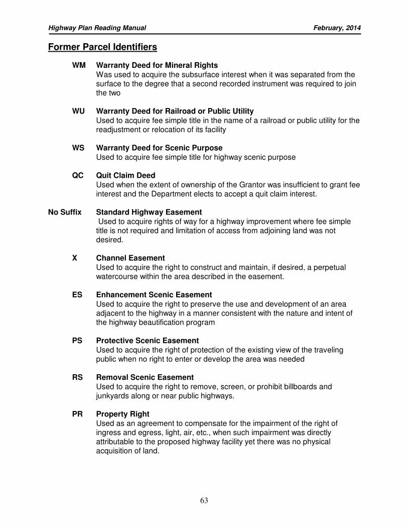
Highway Plan Reading Manual February, 2014
63
Former Parcel Identifiers
WM Warranty Deed for Mineral Rights
Was used to acquire the subsurface interest when it was separated from the surface to the degree that a second recorded instrument was required to join the two
WU Warranty Deed for Railroad or Public Utility
Used to acquire fee simple title in the name of a railroad or public utility for the readjustment or relocation of its facility
WS Warranty Deed for Scenic Purpose
Used to acquire fee simple title for highway scenic purpose
QC Quit Claim Deed
Used when the extent of ownership of the Grantor was insufficient to grant fee interest and the Department elects to accept a quit claim interest.
No Suffix Standard Highway Easement
Used to acquire rights of way for a highway improvement where fee simple title is not required and limitation of access from adjoining land was not desired.
X Channel Easement
Used to acquire the right to construct and maintain, if desired, a perpetual watercourse within the area described in the easement.
ES Enhancement Scenic Easement
Used to acquire the right to preserve the use and development of an area adjacent to the highway in a manner consistent with the nature and intent of the highway beautification program
PS Protective Scenic Easement
Used to acquire the right of protection of the existing view of the traveling public when no right to enter or develop the area was needed
RS Removal Scenic Easement
Used to acquire the right to remove, screen, or prohibit billboards and junkyards along or near public highways.
PR Property Right
Used as an agreement to compensate for the impairment of the right of ingress and egress, light, air, etc., when such impairment was directly attributable to the proposed highway facility yet there was no physical acquisition of land.
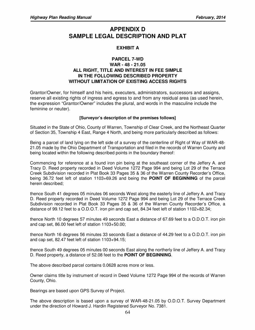
Highway Plan Reading Manual February, 2014
64
APPENDIX D SAMPLE LEGAL DESCRIPTION AND PLAT
EXHIBIT A
PARCEL 7-WD
WAR - 48 - 21.05
ALL RIGHT, TITLE AND INTEREST IN FEE SIMPLE
IN THE FOLLOWING DESCRIBED PROPERTY
WITHOUT LIMITATION OF EXISTING ACCESS RIGHTS
Grantor/Owner, for himself and his heirs, executers, administrators, successors and assigns, reserve all existing rights of ingress and egress to and from any residual area (as used herein, the expression “Grantor/Owner” includes the plural, and words in the masculine include the feminine or neuter).
[Surveyor’s description of the premises follows]
Situated in the State of Ohio, County of Warren, Township of Clear Creek, and the Northeast Quarter of Section 35, Township 4 East, Range 4 North, and being more particularly described as follows: Being a parcel of land lying on the left side of a survey of the centerline of Right of Way of WAR-48-21.05 made by the Ohio Department of Transportation and filed in the records of Warren County and being located within the following described points in the boundary thereof: Commencing for reference at a found iron pin being at the southeast corner of the Jeffery A. and Tracy D. Reed property recorded in Deed Volume 1272 Page 994 and being Lot 29 of the Terrace Creek Subdivision recorded in Plat Book 33 Pages 35 & 36 of the Warren County Recorder’s Office, being 36.72 feet left of station 1103+69.26 and being the POINT OF BEGINNING of the parcel herein described; thence South 41 degrees 05 minutes 06 seconds West along the easterly line of Jeffery A. and Tracy D. Reed property recorded in Deed Volume 1272 Page 994 and being Lot 29 of the Terrace Creek Subdivision recorded in Plat Book 33 Pages 35 & 36 of the Warren County Recorder’s Office, a distance of 99.12 feet to a O.D.O.T. iron pin and cap set, 84.34 feet left of station 1102+82.34; thence North 10 degrees 57 minutes 49 seconds East a distance of 67.69 feet to a O.D.O.T. iron pin and cap set, 86.00 feet left of station 1103+50.00; thence North 16 degrees 56 minutes 33 seconds East a distance of 44.29 feet to a O.D.O.T. iron pin and cap set, 82.47 feet left of station 1103+94.15; thence South 49 degrees 05 minutes 00 seconds East along the northerly line of Jeffery A. and Tracy D. Reed property, a distance of 52.08 feet to the POINT OF BEGINNING. The above described parcel contains 0.0628 acres more or less. Owner claims title by instrument of record in Deed Volume 1272 Page 994 of the records of Warren County, Ohio. Bearings are based upon GPS Survey of Project. The above description is based upon a survey of WAR-48-21.05 by O.D.O.T. Survey Department under the direction of Howard J. Hardin Registered Surveyor No. 7381.
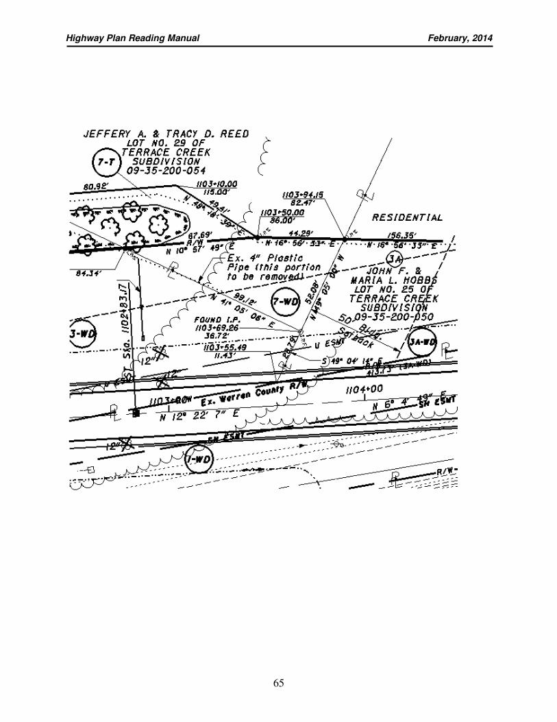
Highway Plan Reading Manual February, 2014
65