highway drainage manual - maryland · manual mary lan d department of f ransportation ... division...
TRANSCRIPT
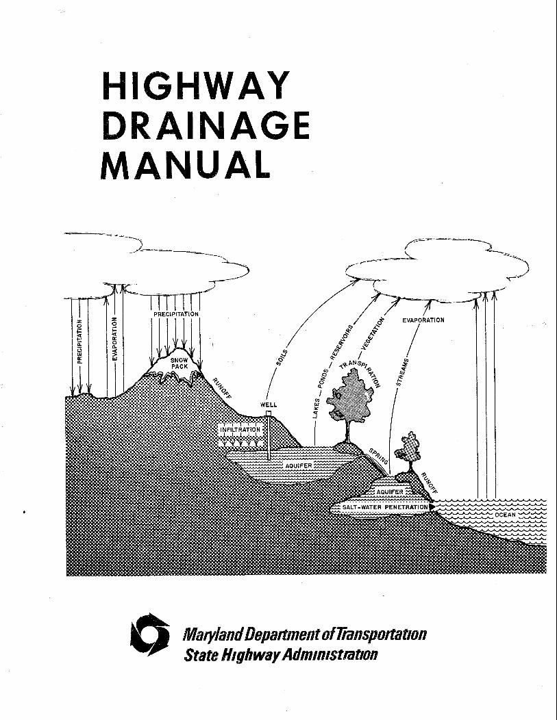
GHWAY
Maryland Depapament of &nspo~at~on State Highway Adm~nfstmtlon

GHWAV
MANUAL
MARY LAN D DEPARTMENT OF f RANSPORTATION
STATE HIGHWAY ADMINISTRATION
PREFACE
I n 1966 House Document 465 was p u b l i s h e d by t h e Task Fo rce on Federa l F l o o d C o n t r o l Po l i c y . Such a c t was l a t e r f o l l o w e d by t h e 1969 Env i ronmen ta l P r o t e c - t i on Act . A f t e r numerous i n t e r v e n i n g l e g a l a c t s assoc i a t e d w i t h env i ronmenta l m a t t e r s , t h e U.S. Water Resources Counc i l pub1 i s h e d t h e f o l l o w i n g document "A U n i f i e d N a t i o n a l Program f o r F l o o d P l a i n Management", da ted September 1979. Such document s e t s f o r t h t h e Federa l requ i remen ts t o meet E x e c u t i v e Order 11998. The S t a t e o f Maryland, s i n c e t h e f o r m a t i o n o f t h e Department o f N a t u r a l Resources, i n 1972, has s t e a d i l y pursued t h e t a s k o f d e v e l o p i n g p l a n s f o r r e g u l a t i n g and /o r a s s i s t i n g i n t h e r e g u l a t i o n o f a c t i v i t i e s w i t h i n t h e 100 y e a r f l o o d p l a i n . The Mary land General Assembly i n an e f f o r t t o more c l o s e l y c o n t r o l S t a t e funded a c t i v i t i e s i n t h e 100 y e a r f l o o d p l a i n , passed t h e "F lood Hazard Management A c t o f 1976.
As one o f t h e means f o r e x e r c i s i n g c o n t r o l over a c t i v i t i e s w i t h i n t h e 100 y e a r f l o o d p l a i n , t h e Water Resources A d m i n i s t r a t i o n promulgated t h e i r "Rules and n-- ~ - L L - - - n e y u I ~ L lor15 govern ing c v n s t r u t t i o n on Non-T ida l l j a t e r s and Fiooci P l a i n s " da ted August 11, 1978 and t h e "Mary land I n t e r i m Watershed Management P o l i c y " o f 1977. The Federa l and S t a t e f l o o d p l a i n r e g u l a t i o n s were i n a c o n s t a n t s t a t e o f change and f o r m a t i o n d u r i n g t h e e n t i r e decade f rom 1970 t o 1980. Such s t a t e o f change n a t u r a l l y caused c o n s i d e r a b l e c o n f u s i o n i n t h e f i e l d s o f h y d r o l o g y and hydrau- l i c s e s p e c i a l l y i n r e l a t i o n t o highway c o n s t r u c t i o n w i t h i n t h e 100 y e a r f l o o d p l a i n .
I n an e f f o r t t o e l i m i n a t e much o f t h e c o n f u s i o n and t o s e t f o r t h c r i t e r i a S t a t e Highway A d m i n i s t r a t i o n (S.H.A.) deems necessary t o meet t h e F e d e r a l and S t a t e r e g u l a t o r y requ i rements , i n c l u d i n g t h o s e o f t h e F e d e r a l Highway A d m i n i s t r a t i o n , t h e S.H.A. has deve loped t h i s p r e s e n t document.
W h i l e s p e c i a l problems may r e q u i r e un ique s o l u t i o n s , t h e des ign o f most d r a i n a g e f a c i 1 i t i e s can be accompl i s h e d by r o u t i n e procedures. T h i s c r i t e r i a w i l l be used i n c o n j u n c t i o n w i t h t h e c u r r e n t Standard P l a t e s o f t h e BOOK OF STANDARDS, HIGHWAY AND INCIDEKTAL STRUCTURES, Mary land S t a t e Highway A d m i n i s t r a t i ~ n .
T h i s document p r i o r t o i t s p r o m u l g a t i o n has been rev iewed by t h e Mary land S t a t e Water Resources A d m i n i s t r a t i o n and t h e B a l t i m o r e O f f i c e o f t h e F e d e r a l Highway A d m i n i s t r a t i o n . S i n c e t h i s document i s a p a r t o f t h e S.H.A. ' s e f f o r t t o comply w i t h Federa l and S t a t e regu1ator.y requ i remen ts , t h e need f o r p e r i o d i c u p d a t i n g i s apparent ; t h e r e f o r e , r e c o r d s o f persons, f i rms, etc., u t i 1 i z i ng t h e s u b j e c t document must be a c c u r a t e l y k e p t f o r u p d a t i n g purposes. Users c o o p e r a t i o n i n t h i s m a t t e r i s r e s p e c t f u l l y requested.
CONTENTS
PREFACE. . . . . . . . . . . . . . . . . . . . . . . . . . . . . . . . . . i
INTRODUCTION
. . . . . . . . . . . . . . . . . . . . . . A. O r g a n i z a t i o n o f Document x v . . . . . . . . . . . . . . . . . . . . . . . . . B. S.H.A. O b j e c t i v e s . xv C. Pub1 i c Invo lvemen t . . . . . . . . . . . . . . . . . . . . . . . . . x v i i D. L o c a t i o n H y d r a u l i c S t u d i e s . . . . . . . . . . . . . . . . . . . . . x v i i E. On ly P r a c t i c a b l e A1 t e r n a t i v e F i n d i n g s . . . . . . . . . . . . . . . . x v i i F. Design Storms. . . . . . . . . . . . . . . . . . . . . . . . . . . . x v i i G. Leve l o f Env i ronmen ta l S t u d i e s by P r o j e c t P l a n n i n g . . . . . . . . x v i i i
. . . . . . . . . . . . . . . . . . . . . . LIST OF TABLES AND CHARTS. x x i - x x i i
iii
PART I . DIVISION OF HIGHWAY DEVELOPMENT
CHAPTER 1 . DESIGN CRITERIA
. . . . . . . . . . . . . . . . . . . . . . . A . S.H.A. Computat ions I -1 -A-1 . . . . . . . . . . . . . . . . . . . . . . . B . P r i v a t e Development I -1 -B-1
CHAPTER 2 . BASIC CONCEPTS
. . . . . . . . . . . . . . . . . . . . . . . . . . . . A . Hydro logy I -2 -A-1
. . . . . . . . . . . . . . . . . . . . . . 1 The R a t i o n a l Method I -2 -A -1 . . . . . . . . . . . . . . . . . . . . . a R u n o f f C o e f f i c i e n t I -2 -A-1 . . . . . . . . . . . . . . . . . . . b Time o f C o n c e n t r a t i o n I-2-A-10 . . . . . . . . . . . . . . . . . . . . . c R a i n f a l l I n t e n s i t y I-2-A-27 . . . . . . . . . . . . . . d . R a i n f a l l I n t e n s i t y C o e f f i c i e n t I-2-A-27 . . . . . . . . . . . . . . . . . . . . . . e . Dra inage Area I-2-A-27
. . . . . . . . . . . . 2 . The S o i l C o n s e r v a t i o n S e r v i c e Methods I -2-A-49 . . . . . . . . . . . . . . . . . . . a . R u n o f f Curve Numbers I-2-A-49 . . . . . . . . . . . . . . . . . . b . Time o f C o n c e n t r a t i o n I -2-A-52 . . . . . . . . . . . . . . . . . . . . . . c . R a i n f a i i Data I-2-A-52 . . . . . . . . . . . . . . d . Dra inage on t h e E a s t e r n Shore I-2-A-52 . . . . . . . . . . . . . . . . . . . . . e . TR-20 I n p u t Data I-2-A-68
B . Hydrau l i cs
. . . . . . . . . . . . . . . . . . . . . . 1 . Mann ing ' s Formula I -2 -B-1 . . . . . . . . . . . . . . . . . . . 2 . The C o n t i n u i t y E q u a t i o n I -2-B-11 . . . . . . . . . . . . . . . . . . 3 . Ent rance C o n t r o l Headwater I -2 -B-11 . . . . . . . . . . . . . . . . . . . 4 . O u t l e t C o n t r o l Headwater I-2-B-12
CHAPTER 3 . OPEN DRAINAGE
A . D i t c h e s . G u t t e r s and Channels
1 . Geiiera: L i m i t a t i o n s . 2 . Design . . . . . . . . 3 . Median D i t c h e s . . . . 4 . Berm D i t c h e s . . . . . 5 . Bench D i t c h e s . . . . 6 . S i d e D i t c h e s . . . . . 7 . S u r f a c e D r a i n D i t c h e s 8 . O u t l e t D i t c h e s . I n l e t
Channel Improvements . B . I n l e t s
. . . . . . . . . . . . . . . . . . . . i-3-A-i . . . . . . . . . . . . . . . . . . . . 1 . 3 . A.l . . . . . . . . . . . . . . . . . . . . I-3-A-1 . . . . . . . . . . . . . . . . . . . . I-3-A-1 . . . . . . . . . . . . . . . . . . . . 1 . 3 . A.l . . . . . . . . . . . . . . . . . . . . I-3-A-1 . . . . . . . . . . . . . . . . . . . . I-3-A-2 D i t c h e s and Othe r . . . . . . . . . . . . . . . . . . . . 1 . 3 . A.2
. . . . . . . . . . . . . . . . . . . . . 1 . General L i m i t a t i o n s I -3 -B-1 . . . . . . . . . . . . . . . . . . . . . . . . 2 . Median I n l e t s I -3-B-1 . . . . . . . . . . . . . . . . . . . . 3 . Standard Curb Openings I -3 -B -1
CONTENTS
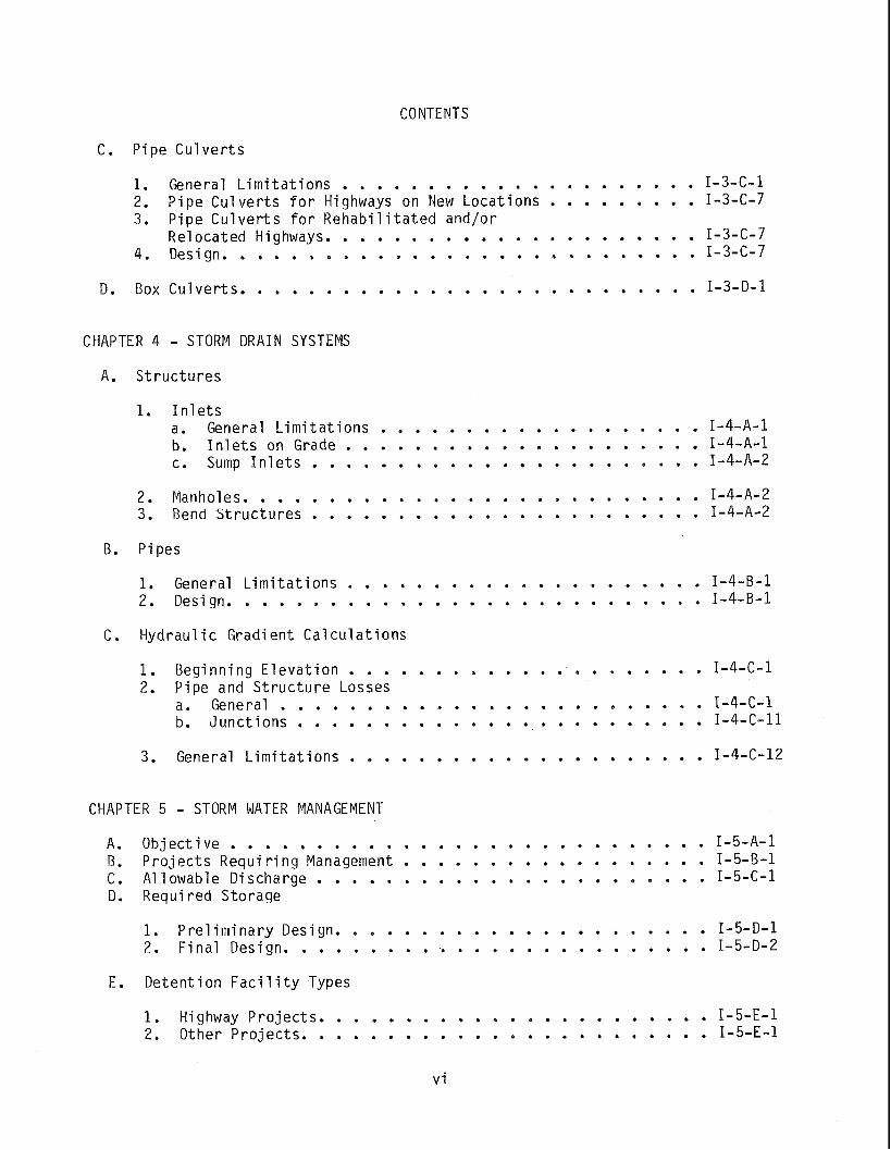
C . P i p e C u l v e r t s
. . . . . . . . . . . . . . . . . . . . . . 1 General L i m i t a t i o n s I -3-C-1 . . . . . . . . . 2 . P i p e C u l v e r t s f o r Highways on New L o c a t i o n s I-3-C-7 3 . P i p e C u l v e r t s f o r R e h a b i l i t a t e d and/or . . . . . . . . . . . . . . . . . . . . . . R e l o c a t e d Highways I-3-C-7 . . . . . . . . . . . . . . . . . . . . . . . . . . . . 4 . Design I-3-C-7
. . . . . . . . . . . . . . . . . . . . . . . . . . . D . Box C u l v e r t s I -3 -D-1
CHAPTER 4 . STORM DRAIN SYSTEMS
A . S t r u c t u r e s
1 . I n l e t s . . . . . . . . . . . . . . . . . . . a . General L i m i t a t i o n s I -4 -A -1 . . . . . . . . . . . . . . . . . . . . . b . I n l e t s on Grade I -4-A-1 . . . . . . . . . . . . . . . . . . . . . . . c . Sump I n l e t s I-4-A-2
. . . . . . . . . . . . . . . . . . . . . . . . . . . . 2 Manholes I-4-A-2 . . . . . . . . . . . . . . . . . . . . . . . . 3 Bend S t r u c t u r e s I-4-A-2
B . Pipes
. . . . . . . . . . . . . . . . . . . . . 1 . General L i m i t a t i o n s I -4 -B-1 . . . . . . . . . . . . . . . . . . . . . . . . . . . . . 2 Design I -4 -B-1
C . Hydrau l i c G r a d i e n t C a l c u l a t i o n s
. . . . . . . . . . . . . . . . . . . . . 1 . B e g i n n i n g E l e v a t i o n I -4-C-1 2 . P i p e and S t r u c t u r e Losses . . . . . . . . . . . . . . . . . . . . . . . . . a . General I -4-C-1 . . . . . . . . . . . . . . . . . . . . . . . . b . J u n c t i o n s I -4-C-11
. . . . . . . . . . . . . . . . . . . . . . 3 General L i m i t a t i o n s I-4-C-12
CHAPTER 5 . STORM WATER MANAGEMENT
. . . . . . . . . . . . . . . . . . . . . . . . . . . . A . O b j e c t i v e I -5 -A -1 . . . . . . . . . . . . . . . . . . 5 . P r o j e c t s R e q u i r i n g Management I -5 -B-1 . . . . . . . . . . . . . . . . . . . . . . . C . A1 1 owable D ischarge I -5-C-1 D . Requ i red S to rage
. . . . . . . . . . . . . . . . . . . . . . . 1 P r e l i m i n a r y Des ign I -5-D-1 . . . . . . . . . . . . . . . . . . . . . . . . . . 2 . F i n a l Des ign I-5-D-2
E . D e t e n t i o n F a c i l i t y Types
. . . . . . . . . . . . . . . . . . . . . . . 1 . Highway P r o j e c t s I -5 -E -1 . . . . . . . . . . . . . . . . . . . . . . . . 2 . Other P r o j e c t s I -5 -E-1

CONTENTS
. . . . . . . . . . . . . . . . . . . . . . . . . . F . Release Rates I -5-F-1 . . . . . . . . . . . . . . . . . . . . . . . . . G Cont ro l S t r uc tu res I-5-G-1
CHAPTER 6 . KARST TOPOGRAPHY
. . . . . . . . . . . . . . . . . . . . . . . . . . . . . . A General I -6-A-1 . . . . . . . . . . . . . . . . . . . . . . . 0 Sinkholes as O u t f a l l s I -6-B-1
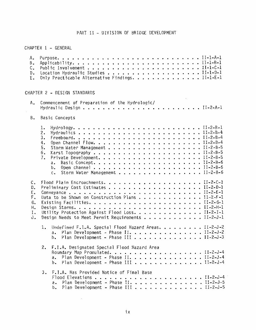
PART I 1 . DIVISION OF BRIDGE DEVELOPMENT
CHAPTER 1 . GENERAL
. . . . . . . . . . . . . . . . . . . . . . . . . . . . . A . Purpose 11-1-A-1 . . . . . . . . . . . . . . . . . . . . . . . . . . B . A p p l i c a b i l i t y 11-1-B-1 . . . . . . . . . . . . . . . . . . . . . . . C . P u b l i c I nvo lvemen t 11-1-C-1 . . . . . . . . . . . . . . . . . . . D . L o c a t i o n H y d r a u l i c S t u d i e s 11-1-0-1 E . Only P r a c t i c a b l e A l t e r n a t i v e F i n d i n g s . . . . . . . . . . . . . . 11-1-E-1
CHAPTER 2 . DESIGN STANDARDS
A . Commencement o f P r e p a r a t i o n o f t h e H y d r o l o g i c / H y d r a u l i c Des ign . . . . . . . . . . . . . . . . . . . . . . . . 11-2-A-1
B . B a s i c Concepts
1 . Hydro1 ogy . . . . . . . . . . . . . . . . . . . . . . . . . . 2 . H y d r a u l i c s . . . . . . . . . . . . . . . . . . . . . . . . . 3 . Freeboard . . . . . . . . . . . . . . . . . . . . . . . . . . . . . . . . . . . . . . . . . . . . . . . . 4 . Open Channel F l o w . . . . . . . . . . . . . . . . . . . 5 . Storm Water Management 6 . K a r s t Topography . . . . . . . . . . . . . . . . . . . . . . . . . . . . . . . . . . . . . . . . . . . 7 . P r i v a t e Development . . . . . . . . . . . . . . . . . . . . . . a . B a s i c Concept
b . Openchanne l . . . . . . . . . . . . . . . . . . . . . . c . Storm Water Management . . . . . . . . . . . . . . . . .
Flood P l a i n Encroachments . . . . . . . . . . . . . . . . . . . . 11-2-C-1 Pre1iminar.y Cos t E s t i m a t e s . . . . . . . . . . . . . . . . . . . 11-2-D-1 Conveyance . . . . . . . . . . . . . . . . . . . . . . . . . . . 11-2-E-1 Data t o be Shown on C o n s t r u c t i o n P l a n s . . . . . . . . . . . . . 11-2-F-1 E x i s t i n g F a c i l i t i e s . . . . . . . . . . . . . . . . . . . . . . . 11-2-G-1 Des ign Storms . . . . . . . . . . . . . . . . . . . . . . . . . . 11-2-H-1 U t i l i t y P r o t e c t i o n A g a i n s t F l o o d Loss . . . . . . . . . . . . . . 11-2-1-1 Des ign Needs t o Meet P e r m i t Requirements . . . . . . . . . . . . 11-2-J-1
. . . . . . . . . i . Undef ined F.I.A. S p e c i a i F l o o d Hazard Areas 11-2-4-2 . . . . . . . . . . . . . . . . a . P l a n Development Phase I 1 11-2-J-2 . . . . . . . . . . . . . . . b . P l a n Development Phase I11 11-2-J-3
2 . F.I.A. Des igna ted S p e c i a l F l o o d Hazard Area Boundary Map Promula ted . . . . . . . . . . . . . . . . . . . 11-2-J-4 a . P l a n Development . Phase I 1 . . . . . . . . . . . . . . . 11-2-J-4
. . . . . . . . . . . . . . . b . P l a n Development Phase 111 11-2-J-4
3 . F.I.A. Has P r o v i d e d N o t i c e o f F i n a l Base . . . . . . . . . . . . . . . . . . . . . . F l o o d E l e v a t i o n s 11-2-J-4 a . P lan Development . Phase I 1 . . . . . . . . . . . . . . . 11-2-J-5 b . P l a n Development . Phase I 1 1 . . . . . . . . . . . . . . 11-2-J-5
CONTENTS
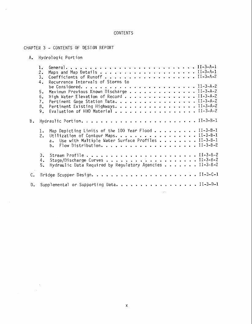
CHAPTER 3 . CONTENTS OF DESIGN REPORT
A . H y d r o l o g i c P o r t i o n
1 . General . . . . . . . . . . . . . . . . . . . . . 2 . Maps and Map D e t a i l s . . . . . . 3 . C o e f f i c i e n t s o f Runoff 4 . Recur rence I n t e r v a l s o f Storms t o . . . . . . . . . . . be Cons idered 5 . Maximum Prev ious Known D ischarge . 6 . High Water E l e v a t i o n o f Record . . . . . . . 7 P e r t i n e n t Gage S t a t i o n Data . . . . . 8 P e r t i n e n t E x i s t i n g Highways . . . . . 9 E v a l u a t i o n o f HlJD M a t e r i a l
. . . . . . . . . . . . . . . . . . . . . . . . B . H y d r a u l i c P o r t i o n 11-3-B-1
. . . . . . . . . . 1 Map D e p i c t i n g L i m i t s o f t h e 100 Year F l o o d 11-3-B-1 . . . . . . . . . . . . . . . . . . 2 U t i l i z a t i o n of Contour Maps 11-3-B-1 . . . . . . . . a . Use w i t h M u l t i p l e Water S u r f a c e P r o f i l e s 11-3-B-1 . . . . . . . . . . . . . . . . . . . . b . Flow D i s t r i b u t i o n 11-3-B-2
. . . . . . . . . . . . . . . . . . . . . . . . 3 S t r e a m p r o f i l e 11-3-B-2 . . . . . . . . . . . . . . . . . . . . 4 S tage ID ischarge Curves 11-3-B-2 . . . . . . . . 5 Hydrau l i c Data Requ i red by R e g u l a t o r y Agencies 11-3-B-2
. . . . . . . . . . . . . . . . . . . . . . C . B r i d g e Scupper Des ign 11-3-C-1
. . . . . . . . . . . . . . . . . D . Supplemental o r S u p p o r t i n g Data 11-3-D-1
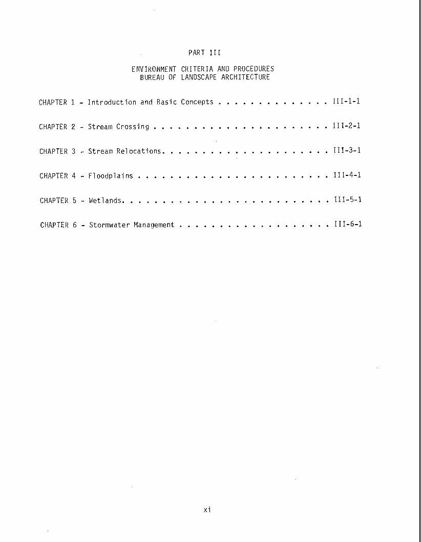
PART I11
ENVIRONMENT CRITERIA AND PROCEDURES BUREAU OF LANDSCAPE ARCHITECTURE
. . . . . . . . . . . . . . CHAPTER 1 . I n t r o d u c t i o n and B a s i c Concepts 111-1-1
. . . . . . . . . . . . . . . . . . . . . . CHAPTER 2 . Stream C r o s s i n g 111-2-1
. . . . . . . . . . . . . . . . . . . . . CHAPTER 3 . Stream R e l o c a t i o n s 111-3-1
. . . . . . . . . . . . . . . . . . . . . . . . CHAPTER 4 . F l o o d p l a i n s 111-4-1
. . . . . . . . . . . . . . . . . . . . . . . . . . CHAPTER 5 . Wetlands 111-5-1
. . . . . . . . . . . . . . . . . . . CHAPTER 6 . Stormwater Management 111-6-1
PART I V APPENDICIES
ALL AREAS OF RESPONSIBILITY
. . . . . . . . . . . . . . . . . . . . . . . . . . . . . . 1 . Glossary IV-1-1
. . . . . . . . . . . . . . . . . . . . . . . . . . . . . 2 . References IV -2 -1
. . . . . . . . . . . . . . . . . . . . . . . . . . . 3 . Design Char ts IV -3 -1
4 . Design o f Cor ruga ted Meta l and . . . . . . . . . . . . . . . . . . . . . . . . . . . A1 umi num Pipes IV-4-1
x i i i
INTRODUCTION
A. O r g a n i z a t i o n o f Document
T h i s document has been assembled i n f o u r p a r t s . P a r t s I and I V p e r t a i n m a i n l y t o t h e hydro1 o g i c / h y d r a u l i c c r i t e r i a deve loped by t h e D i v i s i o n o f Highway Design. P a r t I 1 has been developed j o i n t l y by t h e Bureau o f P r o j e c t P l a n n i n g and t h e Bureau o f B r i d g e Design. P a r t I 1 I has been developed by t h e Bureau o f Landscape A r c h i t e c t u r e . The r e f e r e n c e and Glossary s e c t i o n s o f P a r t I V a r e a p p l i c a b l e t o t h e d i s c i p l i n e s o f a l l t h e S.H.A. r e s p o n s i b i - li t y c e n t e r s .
The D i v i s i o n o f Highway D e s i g n ' s P a r t I and p o r t i o n s o f P a r t I V g e n e r a l l y a p p l y t o d r a i n a g e areas l e s s t h a n 400 acres. An e x c e p t i o n t o t h e 400 a c r e c r i t e r i a i s where t h e h y d r o l o g i c / h y d r a u l i c needs o f l a r g e r d r a i n a g e a reas can be met w i t h t h e use o f p i p e and /o r p i p e a r c h c o n s t r u c t i o n . (Such work t h e n fa1 1 s w i t h i n t h e D i v i s i o n o f Highway Development I s a rea o f r e s p o n s i b i 1 - i t y ) . I n t h e even t t h e d r a i n a g e area i s l e s s t h a n 400 ac res and c o n c r e t e box c u l v e r t , b r i d g e and/or c o n c r e t e a rch c o n s t r u c t i o n i s r e q u i r e d , t h e r e s p o n s i b i l i t y f o r such work w i l l f a l l w i t h i n t h e D i v i s i o n o f B r i d g e Devel opment . The Bureau o f P r o j e c t P l a n n i n g and Bureau o f B r i d g e D e s i g n ' s P a r t I 1 gener - a l l y a p p l i e s t o a reas 400 ac res o r g r e a t e r . As no ted above, r e g a r d l e s s o f t h e s i z e o f t h e d r a i n a g e area, when t h e s t r u c t u r e requ i remen ts cannot be met by t h e use o f p i p e and/or p i p e a r c h c o n s t r u c t i o n , t h e work w i l l f a l l w i t h i n t h e D i v i s i on o f B r i dge Devel opment I s area o f respons i b i 1 i t y . P a r t I 1 1 has been developed by t h e Bureau o f Landscape A r c h i t e c t u r e . Measures as s e t f o r t h t h e r e i n a r e a t tempts by t h e S.H.A. t o m i t i g a t e impac ts caused by S.H.A. a c t i v i t i e s wh ich f a l l w i t h i n t h e 100 y e a r f l o o d p l a i n .
The Bureau o f P r o j e c t P lann ing , i n a d d i t i o n t o P a r t 11, has deve loped m a t e r i a l as necessary f o r t h e i r a rea o f r e s p o n s b i l i t y and has p l a c e d same t h r o u g h o u t t h e f o u r p a r t s as needed.
P a r t I V c o n s i s t s o f a g l o s s a r y , re fe rences , d e s i g n c h a r t s and des igns a ids . The r e f e r e n c e and g f e s s a r y app ly t~ a ? ? p;rts ~f +h- ie LII l a A n m t m n m + uuLulllcllL. Thn I IIc A n e i ucs I nn yll
c h a r t s app ly m a i n l y t o P a r t I, b u t t h e i r use i s n o t n e c e s s a r i l y 1 i r n i t e d t o t h a t p o r t i o n o f t h e document.
B. S.H.A. O b j e c t i v e s :
It shou ld be unders tood t h a t i t i s n o t u n l a w f u l t o encroach on t h e base f l o o d p l a i n . S.H.A. procedures do n o t r e q u i r e n o r encourage a r b i t r a r y span- n i n g o f t h e base f l o o d p l a i n . The S.H.A. r e q u i r e s i d e n t i f i c a t i o n o f p r a c t i - c a b l e a l t e r n a t e s t o c a r r y i n g o u t an a c t i o n i n t h e f l o o d p l a i n . A t t e n t i o n i s d i r e c t e d t o pages VI-13 and 14 o f t h e Reference No. 2. "Trade O f f s " a r e r e f e r r e d t o on pages 11-5 and 111-3 o f t h e above re fe rence . The f o l l o w - i n g a r e o b j e c t i v e s o f t h e S.H.A.:

1. t o coopera te i n a b road and u n i f i e d e f f o r t t o p r e v e n t uneconomic, haza r - dous, o r imcompat ib le use and development o f t h e S t a t e ' s f l o o d p l a i n s .
2. t o a v o i d 1 ong i t u d i n a l encroachments, where p r a c t i c a b l e .
3. t o a v o i d s i g n i f i c a n t encroachments where p r a c t i c a b l e .
4. t o m i n i m i z e impac ts o f highway agency a c t i o n s wh ich a d v e r s e l y a f f e c t base f l o o d p l a i n s .
5. where p r a c t i c a b l e , t o r e s t o r e and p r e s e r v e t h e n a t u r a l and b e n e f i c i a1 f l o o d p l a i n va lues t h a t a r e a d v e r s e l y impacted by highway agency a c t i o n s .
6. t o a v o i d where p r a c t i c a b l e , suppor t o f imcompat iab le f l o o d p l a i n deve l opment.
7. t o be c o n s i s t e n t w i t h t h e i n t e n t o f t h e Standards and c r i t e r i a o f t h e N a t i o n a l F l o o d Insu rance Program, where a p p r o p r i a t e .
8. t o i n c o r p o r a t e "A U n i f i e d N a t i o n a l Program f o r F l o o d P l a i n Management" o f t h e U.S. Water Resources C o u n c i l i n t o S.H.A. procedures.
9. t o comply w i t h t h e l a t e s t Md. Water Resources A d m i n i s t r a t i o n ' s "Ru les and R e g u l a t i o n s Governing C o n s t r u c t i o n on N o n - t i a a i Waters and F i o o d P l a i n s " and t o comply w i t h t h e l a t e s t W.R.A. " I n t e r i m P o l i c y on S to rm Water Management, F l o o d P l a i n Management, F l o o d C o n t r o l and A g r i c u l t u r a l Dra inage" . A t t e n t i o n i s d i r e c t e d t o t h e Md. W.R.A. v a r i a n c e o f a maxi- mum c u m u l a t i v e backwater i n c r e a s e o f 1 f o o t f o r b r i d g e s and c u l v e r t s * . The S.H.A. i n t e r p r e t s t h i s one f o o t v a r i a n c e t o be c o n s i s t e n t w i t h t h e p r e s e n t S t a t e o f t h e a r t wh ich does n o t enab le one t o compute t h e p r e - s e n t and f u t u r e base f l o o d w a t e r s u r f a c e e l e v a t i o n s t o a more reasonab le degree o f accuracy. S.H.A. p r a c t i c e i s t h a t when base f l o o d w a t e r s u r - f a c e e l e v a t i o n s f o r c o n d i t i o n s b e f o r e and a f t e r S.H.A. c o n s t r u c t i o n do n o t change by more t h a n one f o o t , such compu ta t i ons a r e i n t e r p r e t e d t o i n d i c a t e t h a t t h e r e a r e no reasonab ly a c c u r a t e measurable a f f e c t s on t h e base f l o o d w a t e r s u r f a c e e l e v a t i o n s due t o p r e s e n t l y p roposed S.H.A. c o n s t r u c t i o n . Based on such r a t i o n a l e :
a. When changes i n t h e e x i s t i n g and f u t u r e base f l o o d w a t e r s u r f a c e alnnr3+- inn 1 2SS + h 3 " .FAA+ C h - C U A , . , 4 1 1 ,-4-..l., - - + 4 G . , h,, C Z I C V U ~ IUII UI c LIIUII UIIC I V U L L I I C J.II.~. vv I I I 3 1111ply IIUL I I Y uy
r e g i s t e r e d l e t t e r a f f e c t e d p r o p e r t y owners o f t h e h y p o t h e t i c a l f i n d i n g s by t h i s A d m i n i s t r a t i o n .
b. When changes i n t h e e x i s t i n g and f u t u r e base f l o o d wa te r s u r f a c e e l e v a t i o n s var.y by more t h a n one f o o t , t h e S.H.A. w i l l i n t e r p r e t such changes a r e s u l t o f p r e s e n t l y proposed S.H.A. c o n s t r u c t i o n i n t h e base f l o o d p l a i n . Such a d d i t i o n a l i n u n d a t i o n s h a l l be b r o u g h t t o t h e a t t e n t i o n o f a f f e c t e d p r o p e r t y owners. Such a d d i t i o n a l i n u n - d a t e d area s h a l l be purchased, p l a c e d i n des igna ted f l o o d easement o r d e a l t w i t h b y means a c c e p t a b l e t o t h e p r o p e r t y owner, S.H.A., W.R.A. and F.H.W.A., when a p p l i c a b l e .
*W.R.A. v a r i a n c e o f backwa te r i n c r e a s e s up t o one f o o t may n o t be a l l o w e d if s t r u c t u r e s and /o r deve loped p r o p e r t y e x i t w i t h i n t h e a rea o f t h e backwa te r i nc rease .
c. Des ign procedures wh ich n e c e s s i t a t e t h e need f o r t r a d e - o f f s o f N.R.A. and S.H.A. backwa te r s tandards s h o u l d be avo ided as a genera l r u l e . When such des igns a r e p r u d e n t l y j u s t i f i e d , t h e W.R.A. must be c o n t a c t e d i n t h e e a r l y s tages o f p l a n development so as t o o b t a i n concep tua l app rova ls o f des igns which i n c r e a s e s h y p o t h e t i c a l f l o o d i n g by one f o o t o r more t o o t h e r s , even though such i n d i c a t e d f l o o d i n g may be o f an i n s i g n i f i c a n t na tu re .
10. t o comply w i t h a l l t h e l a t e s t a p p l i c a b l e U.S. Army and U.S. Coast Guard p e r m i t programs.
C. Pub1 i c I n v o l vement
I n o r d e r t o meet t h e l a t e s t Federa l and S t a t e r e g u l a t i o n s g o v e r n i n g a c t i v i - t i e s i n t h e 100 y e a r f l o o d p l a i n , t h e S.H.A. has deve loped procedures f o r compl iance o f same. S e c t i o n C, Chapter 1 o f P a r t I 1 covers t h i s s u b j e c t i n d e t a i l , b u t t h e concept a p p l i e s t o a l l 100 y e a r f l o o d p l a i n a c t i v i t y , r e g a r d l e s s o f watershed s i ze .
D. L o c a t i o n H y d r a u l i c S t u d i e s
Such s t u d i e s a r e a v i t a l and necessary p a r t o f P l a n Development. Such s t u d i e s f u r n i s h documentary ev idence t h a t o t h e r a1 t e r n a t i v e s were c o n s i d e r e d i n d e t a i l b e f o r e t h e f i n a l d e c i s i o n s r e l a t i v e t o f l o o d p l a i n a c t i v i t y were adopted. T h i s i t e m i s expounded upon i n S e c t i o n D, Chap te r I P a r t I1 o f t h i s document, b u t t h e p r i n c i p a l s and concepts a p p l y t o a l l a c t i v i t i e s w i t h i n t h e 100 y e a r f l o o d p l a i n , r e g a r d l e s s o f t h e s i z e o f t h e watershed.
E. O n l y P r a c t i c a b l e A l t e r n a t i v e F i n d i n g s
As a necessary requ i remen t t o meet S t a t e and Federa l r e g u l a t o r y r e q u i r e - ments, t h e S.H.A. must show t h a t any a c t i o n wh ich i n c l u d e s a s i g n i f i c a n t encroachment has been s e l e c t e d a f t e r i t has been proven t h a t such s e l e c t e d a c t i o n c o n s t i t u t e s t h e o n l y p r a c t i c a b l e a l t e r n a t e . T h i s s u b j e c t i s d e a l t w i t h i n d e t a i l i n S e c t i o n E, Chap te r 1 o f P a r t II. Such a c t i o n a p p l i e d t o a l l a c t i v i t i e s i n t h e 100 y e a r f l o o d p l a i n , r e g a r d l e s s o f t h e s i z e o f t h e watershed i n v o l v e d .
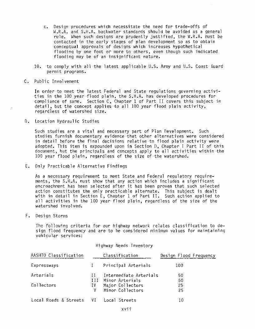
F. Des ign Storms
Thn Cnl 1 n t . , i nn P n i +fin; -\ C,, , l a m h; nh,.,-,, ,A+..,AL-.~, I l ly L I I I v u l I I I ~ I I W ~ J l l c L w v ~ n re:ates c l a s s i f f c a t i o i i t o Se-
s i g n f l o o d f r e q u e n c y and a r e t o be c o n s i d e r e d minimum va lues f o r m a i n t a i n i n g v e h i c u l a r s e r v i c e s :
Highway Needs I n v e n t o r y
AASHTO C l a s s i f i c a t i o n C l a s s i f i c a t i o n Desi gn F l ood Frequency
Expressways I P r i n c i p a l A r t e r i a l s 100
A r t e r i a l s
Co l 1 e c t o r s
I 1 I n t e r m e d i a t e A r t e r i a l s 5 0 111 M i n o r A r t e r i a l s 5 0 I V M a j o r C o l l e c t o r s 2 5
V M i n o r Col l e c t o r s 2 5
L o c a l Roads & S t r e e t s V I Loca l S t r e e t s 10
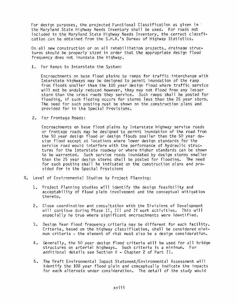
F o r d e s i g n purposes, t h e p r o j e c t e d F u n c t i o n a l C l a s s i f i c a t i o n as g i v e n i n t h e Mary land S t a t e Highway Needs I n v e n t o r y s h a l l be used. F o r roads n o t i n c l u d e d i n t h e Mary land S t a t e Highway Needs I n v e n t o r y , t h e c o r r e c t c l a s s f i - c a t i o n can be o b t a i n e d f r o m t h e S.H.A.'s Bureau o f Highway S t a t i s t i c s .
On a1 1 new c o n s t r u c t i o n o r on a1 1 r e h a b i l i t a t i o n p r o j e c t s , d r a i n a g e s t r u c - t u r e s s h o u l d be p r o p e r l y s i z e d i n o r d e r t h a t t h e a p p r o p r i a t e des ign f l o o d f requency does n o t i n u n d a t e t h e highway.
1. F o r Ramps t o I n t e r s t a t e t h e System:
Encroachments on base f l o o d p l a i n s by ramps f o r t r a f f i c i n t e r c h a n g e w i t h I n t e r s t a t e h ighways may be des igned t o p e r m i t i n u n d a t i o n o f t h e ramp f r o m f l o o d s s m a l l e r t h a n t h e 100 y e a r des ign f l o o d where t r a f f i c s e r v i c e w i l l n o t be undu ly reduced however, t h e y may n o t f l o o d frorn any l e s s e r s t o r m t h a n t h e c r o s s roads t h e y s e r v i c e . Such ramps s h a l l be pos ted f o r f l o o d i n g , i f such f l o d i n g occu rs f o r storms l e s s t h a n t h e 25 y e a r storm. The need f o r such p o s t i n g must be shown on t h e c o n s t r u c t i o n p l a n s and p r o v i d e d f o r i n t h e S p e c i a l P r o v i s i o n s .
2. F o r F r o n t a g e Roads:
Encroachments on base f l o o d p l a i n s b y I n t e r s t a t e h ighway s e r v i c e roads o r f r o n t a g e roads may be des igned t o p e r m i t i n u n d a t i o n o f t h e road f r o m t h e 50 y e a r d e s i g n f i o o a o r des ign f l o o d s s m a i i e r t h a n t h e 50 y e a r ae- s i g n f l o o d except a t l o c a t i o n s where l ower des ign s tandards f o r t h e s e r v i c e r o a d would i n t e r f e r e w i t h t h e performance o f hyd rau l i c s t r u c - t u r e s f o r t h e I n t e r s t a t e roadway o r where h i g h e r s tandards can be shown t o be war ranted. Such s e r v i c e roads i n u n d a t e d by d e s i g n s torms s m a l l e r t h a n t h e 25 y e a r d e s i g n s torms s h a l l be pos ted f o r f l o o d i n g . The need f o r such p o s t i n g s h a l l be i n d i c a t e d on t h e c o n s t r u c t i o n p l a n s and p ro - v i d e d f o r i n t h e S p e c i a l P r o v i s i o n s
G. Leve l o f Env i ronmen ta l S t u d i e s by P r o j e c t P lann ing :
1. P r o j e c t P l a n n i n g s t u d i e s w i l l i d e n t i f y t h e d e s i g n f e a s i b i l i t y and a c c e p t a b i 1 i t y o f f l o o d p l a i n i n v o l vement and t h e concep tua l m i t i g a t i o n t h e r e t o .
2. C lose c o o r d i n a t i o n and c o n s u l t a t i o n w i t h t h e D i v i s i o n s o f Development a . a < l l - ~ n + < * a n - A n n - < m - DL-,-- T T w l I LUllL l l lUtl UUl rlla3tl 11, 111 aiid I?' ~ 6 i . k z c t i v i t i e s . T h i s w i l l e s p e c i a l l y be t r u e where s i g n i f i c a n t encroachments were i d e n t i f i e d .
3. Design Year f l o o d f requency c r i t e r i a may be d i f f e r e n t f o r each f a c i l i t y . C r i t e r i a , based on t h e highway c l a s s i f i c a t i o n , s h a l l be c o n s i d e r e d m i n i - mum c r i t e r i a - t h e e lement o f r i s k must a l s o be a des ign c o n s i d e r a t i o n .
4. Genera l l y , t h e 50 y e a r des ign f l o o d c r i t e r i a w i l l be used f o r a l l b r i d g e s t r u c t u r e s on a r t e r i a l highways. Such c r i t e r i a i s a minimum. F o r a d d i t i o n a l d e t a i l s see S e c t i o n H - Chapter 2 o f P a r t 11.
5. The D r a f t Env i ronmen ta l Impact Sta tement /Env i ronmenta l Assessment w i l l i d e n t i f y t h e 100 y e a r f l o o d p l a i n and c o n c e p t u a l l y i n d i c a t e t h e impac ts f o r each a l t e r n a t e under c o n s i d e r a t i o n . The d e t a i l o f t h e s t u d y wou ld

depend on t h e s i g n f i c a n c e o f t h e f l o o d p l a i n i nvo l vemen t . However, s t u d i e s w i l l a lways p o r t r a y t h e maximum t o l e r a b l e impac ts f o r t h e a l t e r n a t e s cons ide red , so t h a t t h e A d m i n i s t r a t o r may c o n s i d e r t h e "worse case impac t " , a l o n g w i t h t h e m i t i g a t i o n proposed i n t h e d e c i s i o n mak ing process.
6. The F i n a l Env i ronmen ta l Impact Statement/FONSI w i 11 , i f r e q u i r e d , p r o v i de t h e necessary eng i n e e r i ng and e n v i ronmental d e t a i 1 necessary, f o r r e v i e w by t h e r e v i e w and p e r m i t agencies, f o r t h o s e s i g n i f i c a n t encroachments and o f f e r t h e r e v i e w p a r t i e s t h e o p p o r t u n i t y t o weigh and judge t h e p r o p o s a l s and t h u s ease p e r m i t a c t i o n d u r i n g f i n a l des ign.
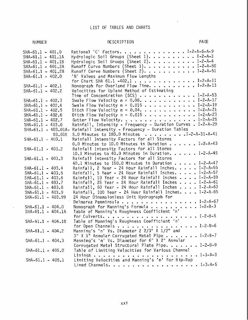
LIST OF TABLES AND CHARTS
NUMBER DESCRIPTION PA GE
. . . . . . . . . . . . . . R a t i o n a l ' C ' Fac to rs I-2-A-6-A-9 . . . . . . . . . . Hydro1 o g i c S o i l Groups (Sheet 1 ) I-2-A-3 . . . . . . . . . . H y d r o l o g i c S o i l Groups (Sheet 2) I-2-A-4 . . . . . . . . . . . Runof f Curve Numbers (Sheet 1) I-2-A-50 . . . . . . . . . . . Runof f Curve Numbers (Sheet 2) I-2-A-51 I N ' Values and Maximum Flow Lengths . . . . . . . . . . . . . f o r Char t SHA 61.1 .402.1 I-2-A-11 . . . . . . . . . . Nomograph f o r Over land Flow Time I-2-A-13 V e l o c i t i e s f o r Upland Method o f E s t i m a t i n g . . . . . . . . . . . . Time o f C o n c e n t r a t i o n (SCS) I-2-A-53 . . . . . . . . . . . . Swale F low V e l o c i t y n 0.06. I-2-A-17 . . . . . . . . . . . . Swale Flow V e l o c i t y n 0.015 I-2-A-19 . . . . . . . . . . . . D i t c h F low V e l o c i t y n 0.04. I-2-A-21 . . . . . . . . . . . . D i t c h F low V e l o c i t y n 0.015 I-2-A-23 . . . . . . . . . . . . . . . . Gut te r F low V e l o c i t y I-2-A-25 R a i n f a l l . I n t e n s i t y . Frequency . D u r a t i o n Curves . I-2-A-29 R a i n f a l l I n t e n s i t y . Frequency . D u r a t i o n Tables . . . . . . . . 5.0 M inu tes t o 180.0 Minutes .1.2.A.31. A.41 R a i n f a l l I n t e n s i t y F a c t o r s f o r a1 1 Storms . . . . . . 0 . 0 M i n u t e s t o 1 0 . 0 M i n u t e s i n D u r a t i o n I-2-A-43 Rai n f a l 1 I n t e n s i t y F a c t o r s f o r a1 1 Storms . . . . . . 10.1 M inu tes t o 40.0 Minutes i n D u r a t i o n I-2-A-45 R a i n f a l l I n t e n s i t y Fac to rs f o r a l l Storms . . . . . 40.1 Minutes t o 150.0 Minutes i n D u r a t i o n I-2-A-47 . . . . . R a i n f a l l . 2 Year . 24 Hour R a i n f a l l Inches I-2-A-55 . . . . . R a i n f a l l . 5 Year . 24 Hour R a i n f a l l Inches I-2-A-57 . . . . R a i n f a l l . 10 Year . 24 Hour R a i n f a l l Inches I-2-A-59 . . . . R a i n f a l l . 25 Year . 24 Hour R a i n f a l l Inches I-2-A-61 . . . . . R a i n f a l l . 50 Year 24 Hour R a i n f a l l Inches I-2-A-63 . . . . R a i n f a l l . PO0 Year . 24 Hour R a i n f a l l Inches I-2-A-65 24 Hour Dimensionless U n i t Hydrograph f o r . . . . . . . . . . . . . . . . Delmarva Penn insu la I-2-A-67 . . . . . . . . . . Nomograph f o r Manning' s Formula I-2-B-3 Table o f Manning's Roughness C o e f f i c i e n t ' n ' . . . . . . . . . . . . . . . . . . . . f o r C u l v e r t s 1-2-6-5 Table o f Manning 's Roughness C o e f f i c i e n t ' n ' . . . . . . . . . . . . . . . . . f o r Open Channels I-2-B-6 Manning's ' n ' Vs . Diameter 2 213" X 1 /2" and . . . . . . . 3 " X 1" Annu la r Corrugated Meta l P i p e I-2-B-7 Manning's ' n ' Vs . Diameter f o r 6 " X 2" Annular . . . . . . . Corrugated Meta l S t r u c t u r a l P l a t e P ipe I-2-B-9 Table o f L i m i t i n g V e l o c i t i e s f o r Var ious Channel . . . . . . . . . . . . . . . . . . . . . . L i n i n g s I-3-A-3 L i m i t i n g V e l o c i t i e s and Manning 's I n ' f o r Rip-Rap . . . . . . . . . . . . . . . . . . . L ined Channel s I-3-A-5
x x i
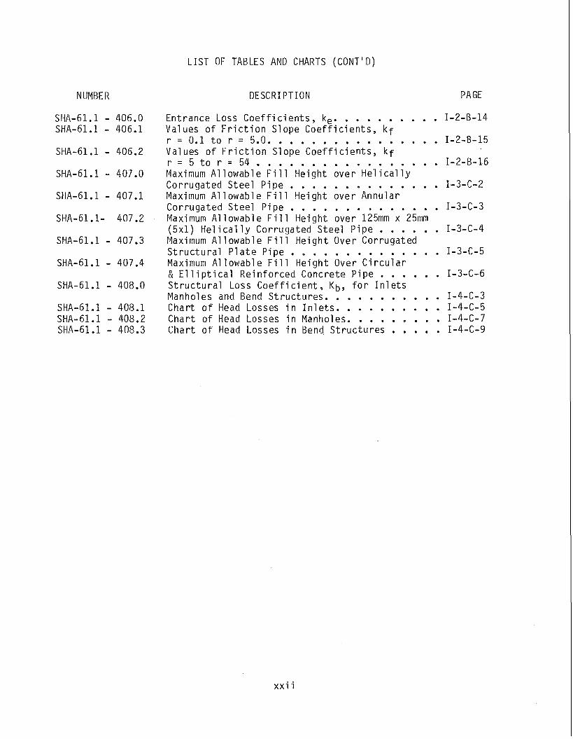
LIST OF TABLES AND CHARTS (CONT'D)
NUMBER DESCRIPTION PAGE
. . . . . . . . . . Ent rance Loss C o e f f i c i e n t s . ke I-2-B-14 Val ues o f F r i c t i o n S lope C o e f f i c i e n t s . k f r = 0.1 t o r = 5.0. . . . . . . . . . . . . . . . 1-2-9-15 Val ues o f F r i c t i o n S lope C o e f f i c i e n t s . k f
= . . . . . . . . . . . . . . . . . r = 5 t o r 54 I-2-B-16 Maximum A l l o w a b l e F i l l He igh t o v e r H e l i c a l l y . . . . . . . . . . . . . . Cor ruga ted S t e e l P i p e I-3-C-2 Maximum A1 1 owabl e F i l l H e i g h t o v e r Annu la r . . . . . . . . . . . . . . Cor ruga ted S t e e l P i p e I-3-C-3 Maximum A l l o w a b l e F i l l H e i g h t ove r 125mm x 25mm . . . . . . (5x1) H e l i c a l l y Cor ruga ted S t e e l P i p e I-3-C-4 Maximum A1 1 owabl e F i l l H e i g h t Over Cor ruga ted . . . . . . . . . . . . . . S t r u c t u r a l P l a t e P i p e I-3-C-5 Maximum A1 l o w a b l e F i l l H e i g h t Over C i r c u l a r . . . . . . & E l l i p t i c a l R e i n f o r c e d Conc re te P i p e I-3-C-6 S t r u c t u r a l Loss C o e f f i c i e n t . Kb. f o r I n 1 e t s . . . . . . . . . . . Manholes and Bend S t r u c t u r e s I-4-C-3 . . . . . . . . . . C h a r t o f Head Losses i n I n l e t s I-4-C-5 . . . . . . . . . C h a r t o f Head Losses i n Manholes I - 4 4 - 7 . . . . . C h a r t o f Head Losses i n Bend S t r u c t u r e s I-4-C-9
x x i i
PART I
C R I T E R I A AND PROCEDURES
FOR
HYDROLOGIC AND HYDRAULIC COMPUTATIONS
- -- k UK
DRAINAGE AREAS LESS THAN 400 ACRES
MARYLAND STATE HIGHWAY A D M I N I S T R A T I O N
D I V I S I O N OF HIGHWAY DEVELOPMENT
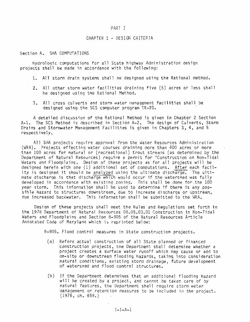
CHAPTER 1 - DESIGN CRITERIA
S e c t i o n A. SHA COMPUTATIONS
Hydro1 o q i c compu ta t i ons f o r a1 1 S t a t e h ighway Admi n i s t r a t i 0 1 1 d e s i g n p r o j e c t s s h a l l be made i n accordance w i t h t h e f o l l o w i n g :
1. A l l s t o r m d r a i n systems s h a l l be des igned u s i n g t h e R a t i o n a l method.
2. A l l o t h e r s t o r m w a t e r f a c i l i t i e s d r a i n i n g f i v e ( 5 ) a c r e s o r l e s s s h a l l be des igned u s i n g t h e R a t i o n a l Method.
3. A1 1 c r o s s c u l v e r t s and s t o r m w a t e r management f a c i l i t i e s sha l l be des igned u s i n g t h e SCS computer program TR-20.
A d e t a i l e d d i s c u s s i o n o f t h e R a t i o n a l Method i s g i v e n i n Chapter 2 S e c t i o n A-1. The SCS Method i s d e s c r i b e d i n S e c t i o n A-2. The d e s i g n o f C u l v e r t s , S torm D r a i n s and S to rmwate r Management F a c i l i t i e s i s g i v e n i n Chap te rs 3 , 4, and 5 r e s p e c t i v e l y .
A l l SHA p r o j e c t s i -eqt i i r? app rova l f ro i i i t h e Gate7 R e s o ~ r c e s A d m i n i s t r a t i o n (WRA). P r o j e c t s e f f e c t i n g w a t e r cou rses d r a i n i n g more t h a n 400 acres o r more t h a n 100 ac res f o r n a t u r a l o r ( r e c r e a t i o n a l ) t r o u t s t reams ( a s de te rm ined b y t h e Department o f N a t u r a l Resources) r e q u i r e a p e r m i t f o r " C o n s t r u c t i o n on Non-T ida l Waters and F l o o d p l a i n s . Des ign o f t h e s e p r o j e c t s as f o r a1 1 p r o j e c t s w i l l be des igned h e r e i n w i t h one ( 1 ) a d d i t i o n a l s e t o f compu ta t i ons . A f t e r each f a c i l - i t y i s des igned i t s h o u l d be a n a l y z e d u s i n g t h e u l t i m a t e d i s c h a r g e . The u l t i - mate d i s c h a r g e i s t h a t d i s c h a r g e wh ich wou ld o c c u r i f t h e wa te rshed was f u l l y deve loped i n accordance w i t h e x i s t i n q zon inq. T h i s s h a l l be done f o r t h e 100 y e a r storm. T h i s i n f o r m a t i o n s h a l l be used t o d e t e r m i n e i f t h e r e i s any pos- s i b l e haza rd t o s t r u c t u r e s downstream, due t o i ncrease d i scharge o r ups t ream, due i n c r e a s e d backwater . T h i s i n f o r m a t i o n s h a l l be s u b m i t t e d t o t h e WRA.
Des ign o f t h e s e p r o j e c t s s h a l l meet t h e Ru les and R e g u l a t i o n s s e t f o r t h i n t h e 1978 Depar tment o f N a t u r a l Resources 08.05.03.01 C o n s t r u c t i o n i n Non-T ida l Waters and F l o o d p l a i n s and S e c t i o n 8-905 of t h e N a t u r a l Resources A r t i c l e Anno ta t& Code o f Mary land wh ich i s r e p r i n t e d beiow:
8-905. F l ood c o n t r o l measures i n S t a t e c o n s t r u c t i o n p r o j e c t s .
( a ) B e f o r e a c t u a l c o n s t r u c t i o n o f a1 1 S t a t e p lanned o r f i n a n c e d c o n s t r u c t i o n p r o j e c t s , t h e Department s h a l l d e t e r m i n e whe the r a p r o j e c t c r e a t e s a s u r f a c e w a t e r r u n o f f wh ich may cause o r add t o o n - s i t e o r downstream f l o o d i n g hazards , t a k i n g i n t o c o n s i d e r a t i o n n a t u r a l c o n d i t i o n s , e x i s t i n g s t o r m d r a i n a g e , f u t u r e development o f wa te rshed and f l o o d c o n t r o l s t r u c t u r e s .
( b ) I f t h e Department de te rm ines t h a t an a d d i t i o n a l f l o o d i n g h a z a r d w i l l be c r e a t e d by a p r o j e c t , and cannot be t a k e n c a r e o f by n a t u r a l f e a t u r e s , t h e Department s h a l l r e q u i r e s t o r m w a t e r management o r r e t e n t i o n measures t o be i n c l u d e d i n t h e p r o j e c t . (1976, ch. 659.)

S e c t i o n B - PRIVATE DEYELOPMENT
1. General
It i s d e s i r a b l e t h a t s t o r m d r a i n and s t o r m w a t e r management f a c i 1 i t i e s f o r a l l p r i v a t e developments be des igned t o con fo rm w i t h t h e SHA c r i t e r i a s e t f o r t h i n t h i s p u b l i c a t i o n . However, t h e degree o f c o n t r o l e x e r c i s e d by t h e S t a t e Highway A d m i n i s t r a t i o n w i l l d i f f e r a c c o r d i n g t o t h e e x t e n t t o + ih i ch t h e deve- l o p e r ' s c o n s t r u c t i o n i s d i r e c t l y i n v o l ved w i t h S t a t e Highway f a c i l S t i e s .
A l l i n l e t s , p i p e s and o t h e r s t o r m d r a i n f a c i l i t i e s c o n s t r u c t e d w i t h i n t h e S t a t e Highway A d m i n i s t r a t i o n ' s r i g h t o f way must conform w i t h t h e same c r i t e r i a used f o r t h e d e s i g n o f S t a t e Highway A d m i n i s t r a t i o n p r o j e c t s and must be rev iewed and approved b y t h e S t a t e Highway A d m i n i s t r a t i o n .
I f t h e proposed d r a i n a g e f a c i l i t i e s f r o m t h e development a r e t o connect d i r e c t l y t o S t a t e Highway A d m i n i s t r a t i o n d r a i n a g e f a c i 1 i t i e s f rom ups t ream o r downstream, t h e o n - s i t e s t o r m d r a i n f a c i l i t i e s must con fo rm w i t h t h e S t a t e Highway Admini s t r a t i o n ' s c r i t e r i a . I f t h e development i t s e l f d r a i n s t o w a r d t h e s t a t e h ighway, t h e s t o r m w a t e r management f a c i l i t i e s must a l s o con fo rm w i t h t h i s c r i t e r i a . P l a n s f o r t h e s e p r o j e c t s must be rev iewed and approved by t h e S t a t e Highway A d m i n i s t r a t i o n .
I f t h e proposed d r a i n a q e f a c i l i t i e s do n o t connect d i r e c t l y t o S t a t e Highway A d m i n i s t r a t i o n d r a i n a g e f a c i l i t i e s , t h e S t a t e Hlghway A d m i n i s t r a t i o n w i l l r e v i e w t h e o n - s i t e d r a i n a g e system and s t o r m w a t e r management f a c i 7 i t i e s . Compl iance w i t h t h e S t a t e Highway A d m i n i s t r a t i o n ' s comments w i l l n o t be manda- t o r y ; b u t i f t h e d e v e l o p e r e l e c t s n o t t o comply, t h e S t a t e Highway A d m i n i s t r a - t i o n w i l l h o l d t h e d e v e l o p e r l i a b l e f o r damages t o t h e highway and f o r c o r - r e c t i v e a c t i o n s h o u l d f l o o d i n g o f t h e highway r e s u l t f r o m t h e d e v e l o p e r ' s c o n s t r u c t i o n .
The f o l l o w i n g p rocedures w i l l be used i n r e v i e w i n g hyd ro1 o g i c c o m p u t a t i o n s s u b m i t t e d t o t h e S t a t e Highway A d m i n i s t r a t i o n and 1:t i s recommended t h a t t h e y be used by t h e d e v e l o p e r ' s e n g i n e e r i n p r e p a r i n g h i s d e s i g n compu ta t i ons .
1. A l l s t o r m d r a i n systems w i l l be r e v i e w e d u s i n g t h e R a e i o n a l Method.
2. A l l s t o r m w a t e r f a c i l i t i e s d r a i n i n g f i v e ( 5 ) ac res o r l e s s w i l l b e r e v i e w e d u s i n q t h e R a t i o n a l Method.
3. A1 1 c r o s s c u l v e r t s and s t o r m w a t e r management f a c i l i t i e s d r a i n i n g more t h a n f i v e ( 5 ) ac res w i l l be r e v i e w e d u s i n g t h e " U n i t e d S t a t e s S o i l C o n s e r v a t i o n S e r v i c e Hydrograph Method" u t i 1 ' z i ng e . i ~ h e r (1) t h e TR-20 computer program o r ( 2 ) t h e TR-55 t a b u l a r Hydrograph Method.
2. C o n t r o l S t r u c t u r e s
I f t h e d e v e l o p e r ' s c o n t r o l s t r u c t ~ r e i s connecxed d i r e c e . / y t o a S t a t e Highway Admi n i s t r a t i o n c u l v e r t , some means o f p h y s i c a l access i ! ; ~ ~ s i be p r o v i d e d a t t h e r i g h t - o f - w a y l i n e . The C o n t r o l s t r ~ c z u r e s musc be s i z e d f o r p r o p e r 2-year , 10 -yea r , and 100-year r e l e a s e r a t e s r e g a r d l e s s o f ~ h e s i z e of t h e p i p e o r o r i f i c e requ red . (See Chap te r I V - S l o r ~ ~ ~ ~ a t e r Management j
I n a1 1 ,cases t h e d e s i g n e r s h o u l d cons i i l - t f s d e r a i , 1oc;l a n d ozher s t a t e agenc ies f o r a d d i t i o n a l s t o r m w a t e r management r e g u l a t i o n s ,
I -1-B-1
PART 1
CHAPTER 2 - BASIC CONCEPTS
S e c t i o n A.
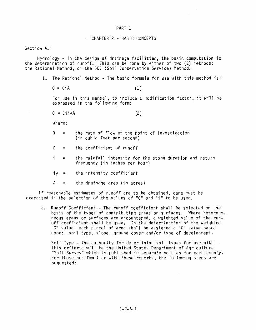
Hydro logy - I n t h e d e s i g n o f d ra inage f a c i l i t i e s , t h e b a s i c compu ta t i on i s t h e d e t e r m i n a t i o n o f r u n o f f . T h i s can be done by e i t h e r o f two ( 2 ) methods: t h e R a t i o n a l Method, o r t h e SCS ( S o i l C o n s e r v a t i o n S e r v i c e ) Method.
1. The R a t i o n a l Method - The b a s i c f o r m u l a f o r use w i t h t h i s method i s :
Q = CiA (1 1
For use i n t h i s manual, t o i n c l u d e a m o d i f i c a t i o n f a c t o r , i t w i l l b e expressed i n t h e f o l l o w i n g form:
where:
Q = t h e r a t e o f f l o w a t t h e p o i n t o f i n v e s t i g a t i o n ( i n c u b i c f e e t p e r second)
C = t h e c o e f f i c i e n t o f r u n o f f
i = t h e r a i n f a l l i n t e n s i t y f o r t h e s to rm d u r a t i o n and r e t u r n f requency ( i n i nches p e r hou r )
if = t h e i n t e n s i t y c o e f f i c i e n t
A = t h e d r a i n a g e area ( i n a c r e s )
I f reasonab le es t ima tes o f r u n o f f a r e t o be ob ta ined , c a r e must be e x e r c i s e d i n t h e s e l e c t i o n o f t h e va lues o f " C " and " i " t o be used.
a. R u n o f f C o e f f i c i e n t - The r u n o f f c o e f f i c i e n t s h a l l be s e l e c t e d on t h e b a s i s o f t h e t y p e s o f c o n t r i b u t i n g areas o r su r faces . Where he te roge- neous areas o r s u r f a c e s a r e encountered, a we igh ted v a l u e o f t h e run- o f f c o e f f i c i e n t s h a l l be used. I n t h e d e t e r m i n a t i o n o f t h e we igh ted I! ,. I, L - va lue , each p a r c e l o f a rea s h a i i be ass igned a ';Cii v a l u e based
upon: s o i l t y p e , s lope , ground c o v e r and/or t y p e o f development.
S o i l Type - The a u t h o r i t y f o r d e t e r m i n i n g s o i l t y p e s f o r use w i t h t h i s c r i t e r i a w i l l be t h e U n i t e d S t a t e s Department o f A g r i c u l t u r e " S o i l Survey" wh ich i s p u b l i s h e d i n s e p a r a t e volumes f o r each county . F o r t h o s e n o t f a m i l i a r w i t h t h e s e r e p o r t s , t h e f o l l o w i n g s t e p s a r e suggested:
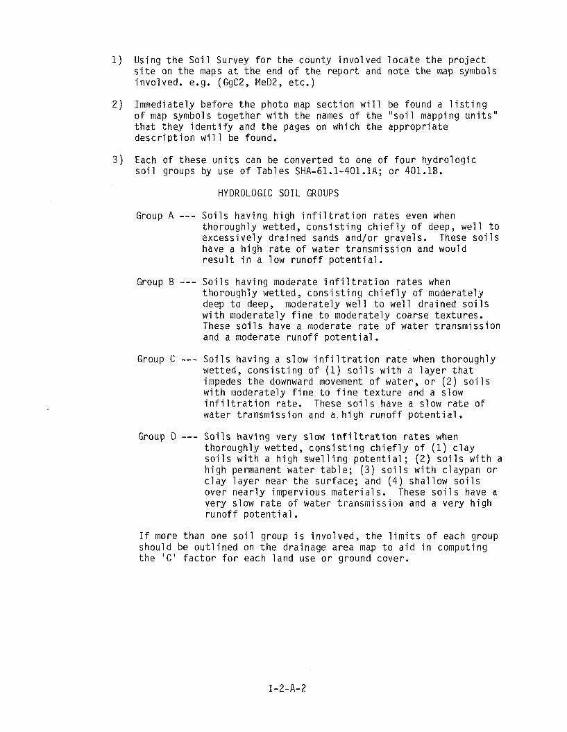
1 ) Using t h e S o i l Survey f o r t h e county i n v o l v e d l o c a t e t h e p r o j e c t s i t e on t h e maps a t t h e end o f t h e r e p o r t and no te t h e map symbols invo lved . e.g. (GgC2, MeD2, etc.)
2 ) Immediately be fo re t h e photo map s e c t i o n w i l l be found a l i s t i n g o f map symbols t oge the r w i t h t h e names o f t h e " s o i l mapping u n i t s " t h a t they i d e n t i f y and t h e pages on which t h e app rop r i a t e d e s c r i p t i o n w i l l be found.
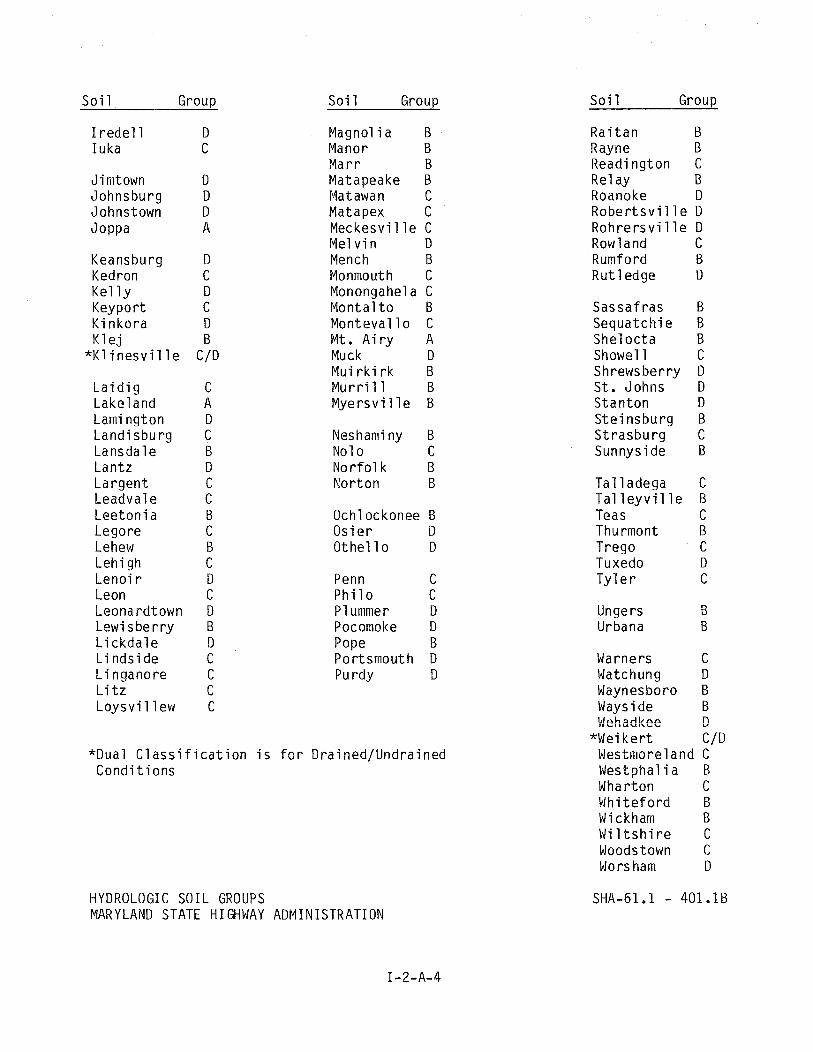
3 ) Each o f these u n i t s can be conver ted t o one o f f o u r h y d r o l o g i c s o i l groups by use o f Tables SHA-61.1-401.1A; o r 401.1B.
HYDROLOGIC SOIL GROUPS
Group A --- S o i l s hav ing h i gh i n f i l t r a t i o n r a t e s even when thorough ly wetted, c o n s i s t i n g c h i e f l y o f deep, w e l l t o excess i ve l y d ra ined sands and/or grave ls . These s o i l s have a h igh r a t e o f wa te r t r ansm iss i on and would r e s u l t i n a low r u n o f f p o t e n t i a l .
Group B --- S o i l s hav ing moderate i n f i l t r a t i o n r a t e s when t ho rough l y wet ted, cons i s t i n g c h i e f l y o f moderate ly deep t o deep, moderate ly we1 1 t o we1 1 d ra i ned so i 1s w i t h moderate ly f i ne t o moderate ly coarse t ex tu res . -. lnese s o i l s have a moderate r a t e o f water t ransmiss ion and a moderate r u n o f f p o t e n t i a l .
Group C --- S o i l s hav ing a s low i n f i l t r a t i o n r a t e when t ho rough l y wetted, c o n s i s t i n g o f ( 1 ) s o i l s w i t h a l a y e r t h a t impedes t h e downward movement o f water, o r ( 2 ) so i 1s w i t h moderately f i n e t o f i n e t e x t u r e and a s low i n f i l t r a t i o n r a te . These s o i l s have a s low r a t e o f water t r ansm iss i on and a, h i g h r u n o f f p o t e n t i a1 .
Group D --- S o i l s hav ing very slow i n f i l t r a t i o n r a t e s when t ho rough l y wetted, c o n s i s t i n g c h i e f l y o f ( 1 ) c l a y s o i l s w i t h a h i g h s w e l l i n g p o t e n t i a l ; ( 2 ) s o i l s w i t h a h i g h permanent water t a b l e ; ( 3 ) s o i l s w i t h c laypan o r c l a y l a y e r near t h e sur face; and ( 4 ) sha l low s o i l s over n e a r l y imperv ious m a t e r i a l s . These s o i l s have a .,- -., v r r y slow r a t e o f water t ra i i sn i i ss ion and a v e r y h i g h r u n o f f p o t e n t i a l .
I f more than one s o i l group i s invo lved , t h e l i m i t s o f each group should be o u t l i n e d on t h e dra inage area map t o a i d i n computing t h e ' C ' f a c t o r f o r each l a n d use o r ground cover.
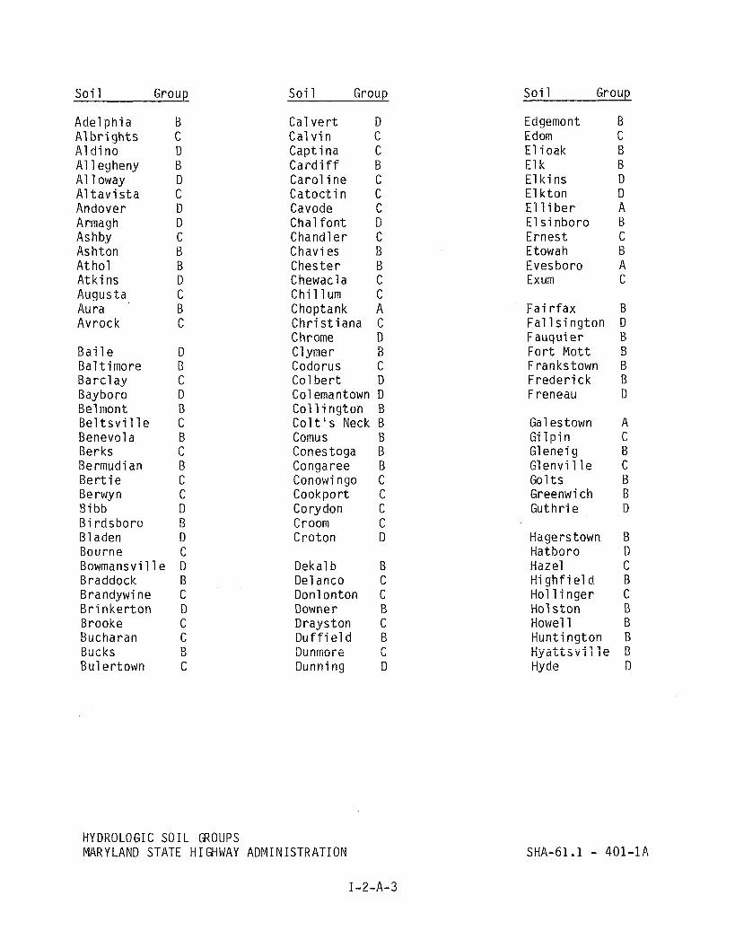
Soi 1 G r o u ~
Adel p h i a A1 b r i gh ts A1 d i no A1 1 egheny A1 1 oway A1 t a v i s t a Andover Armagh Ashby Ash t on A t ho l A t k i ns Augusta Aura Avrock
B a i l e D Ba l t imo re B Ba rc l ay C Bayboro D Belmont B B e l t s v i i i e C Benevol a B Berks C Bermudi an B B e r t i e C Be rwyn C B i bb D B i rdsboro B B l aden D Bourne C Bowmansvi 11 e D Braddock B Brandywine C B r i n k e r t o n D Brooke C Bucharan C R o ~ r l , r U U L r \ J DU Bul er town C
Soi 1 Group
Cal v e r t D Cal v i n C Capt i na C C a r d i f f B C a r o l i n e C C a t o c t i n C Cavode C Cha l f on t D Chandler C Chavi es B Chester B Chewacla C C h i l l u m C Choptank A C h r i s t i a n a C Chrome D C l ymer B Codorus C Col b e r t D Col emantown D C o l l i n g t o n B C o i t ' s Neck B Comus B Conestoga B Congaree B Conowingo C Cookport C Corydon C Croom C Croton D
Dekal b B Del anco C Donlonton C Downer B Drayston C D u f f i e l d B Biiiiiiiore C Dunning D
HYDROLOGIC SOIL GROUPS MARYLAND STATE HIGHWAY ADMINISTRATION
Soi 1 Group
Edgemont B Edom C E l i oak B E l k B E l k i ns D E l k t on D E l 1 i be r A E l s i n b o r o B Ernes t C Etowah B Eves boro A Exum C
F a i r f a x B Fa1 1 s i ngton D Fauquier B F o r t M o t t B Frankstown B F rede r i c k B F reneau D
Galestown A G i l p i n C Glenei g B G l e n v i l l e C Go1 t s B Greenwich B Guth r ie D
Hagerstown B Hatboro D Hazel C H i g h f i e l d B H o l l i n g e r C Hol s t o n B Howel 1 B Hunt ing ton B Hyatis.". i i -ie B
Hyde D
S o i 1 Group
I r e d e l 1 D Iuka C
Jimtown D Johnsburg D Johnstown D JoPPa A
Keansburg D Kedron C Ke l l y D Keypor t C K i nko ra D K l e j B
" K l i n e s v i l l e C/D
L a i d i g Lake land Lami ng ton Land i sbu r g Lansda le i a n t z L a r g e n t Leadval e L e e t o n i a Legore Lehew L e h i gh Leno i r Leon Leona r d t o w n L e w i s b e r r y L i c k d a l e L i n d s i d e L i nganore L i t z L o y s v i 1 1 ew
So i 1 Group
Magnol ia B Manor B M a r r B Matapeake B Matawan C Matapex C Meckesvi 1 l e C Me1 v i n D Mench B Monmouth C Monongahel a C M o n t a l t o B Monteval l o C Mt. A i r y A Muck D Mui r k i r k B M u r r i 11 B M y e r s v i l l e B
Neshaminy B No1 o C N o r f o i i< €3 No r ton B
Ochl ockonee B O s i e r D Othe l l o D
Penn C P h i l o C P l ummer D Pocomoke D Pope B Por tsmouth D Pu r d y D
*Dual C l a s s i f i c a t i o n i s f o r Dra ined/Undra ined C o n d i t i o n s
HYDROLOGIC SOIL GROUPS MARYLAND STATE HIGHWAY ADMINISTRATION
So i 1 Group
Rai t a n B Rayne B Read ington C Re1 ay B Roanoke D R o b e r t s v i l l e D R o h r e r s v i l l e D Rowland C Rumford B Rut1 edge D
Sassa f ras Sequatch i e She1 o c t a Showel 1 Shrewsberry St . Johns S t a n t o n S t e i n s h u r g S t r a s b u r g Sunnyside
T a l l a d e g a C T a l l e y v i l l e B Teas C Thu rmont B Trego C Tuxedo D T y l e r C
Unge r s B Urbana B
Warners C Watchung D Waynesboro B Ways i de B gehadkee D
*Wei k e r t C/D Westmoreland C Westphal i a B Wharton C M h i t e f o r d B Wickham B M i l t s h i r e C Woodstown C Wors ham D

Slope - Photogrammetr ic Maps, U.S.G.S. Quadrang le maps o r p r e l i m i - n a r y survey s h o u l d be used t o d e t e r m i n e e x i s t i n g ground s lopes. C o n s t r u c t i o n p l a n s and s i t e g r a d i n g p l a n s w i l l p r o v i d e d a t a f o r d e t e r m i n i n g t h e proposed ground s lopes.
Ground Cover - A e r i a l Photographs may be used t o make a p r e l i m i n a r y d e t e r m i n a t i o n o f ground cove r i n r u r a l a reas, b u t t h i s da ta s h o u l d a lways be con f i rmed by a f i e l d i n s p e c t i o n o f t h e e n t i r e d r a i n a g e area. Values o f t h e ' C ' f a c t o r a r e s e l e c t e d f r o m T a b l e SHA 61.1-401.0 P a r t 1 RURAL LAND USES OR PARTS 2A and B - AGRICULTURAL LAND USES.
Type o f Development - Whenever p l a n s a r e a v a i l a b l e f o r e i t h e r e x i s t i n g o r proposed deve loped areas, t h e d r a i n a g e a rea s h o u l d be reduced t o r o o f a reas , v a r i o u s t y p e s o f paved areas, and areas o f v a r i o u s v e g e t a t i v e types. I f d e t a i l e d p l a n s a r e n o t a v a i l a b l e , t h e ' C ' f a c t o r can be computed f o r genera l c a t a g o r i e s t o r e f l e c t s l o p e and s o i l group and, i n t h e case o f r e s i d e n t i a l l o t development, a c t u a l l o t s i z e . Urban. l a n d use " C " f a c t o r s a r e l i s t e d on p a r t 3 o f T a b l e SHA 61.1-401.0.
The f o r m u l a f o r t h e we igh ted ' C ' f a c t o r i s :
Where A1, A2 ... A i a r e subareas w i t h i n a d r a i n a g e a rea C 1 , C2 ... C i a r e c o r r e s p o n d i n g r u n o f f c o e f f i c i e n t s f o r t h e subareas.
T h i s f o r m u l a may be expanded f o r any number o f subareas, A i .
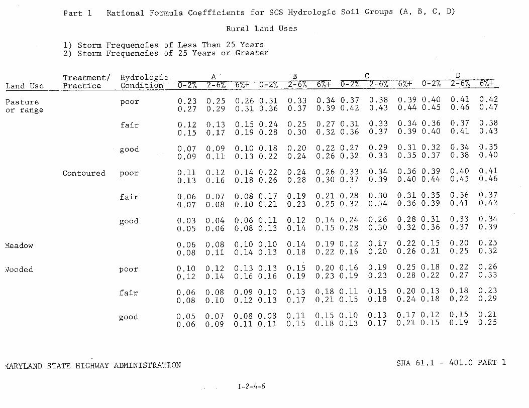
Part 1 Rational Formula Coefficients for SCS Hydrologic Soil Groups (A, B, C, D)
Rural Land Uses
1) Storm Frequencies of Less Than 25 Years 2) Storm Frequencies of 25 Years or Greater
~reatment/ Hydrologilc A 13 C D Condition 0-2% 2-67, 6%+ 0-2% 2-67, 6%+ 0-2% 2-6% 6%+ 0-2% 2-6% 6%+ Land Use Practice
Pasture or range
poor 0.23 0.25 0.26 0.31 0.33 0.34 0.37 0.38 0.39 0.40 0.41 0.42 0.27 0.29 0.31 0.36 0.37 0.39 0.42 0.43 0.44 0.45 0.46 0.47
fair 0.12 0.13 0.15 0.24 0.25 0.27 0.31 0.33 0.34 0.36 0.37 0.38 0.15 0.17 0.19 0.28 0.30 0.32 0.36 0.37 0.39 0.40 0.41 0.43
good 0.07 0.09 0.10 0.18 0.20 0.22 0.27 0.29 0.31 0.32 0.34 0.35 0.09 0.11 0.13 0.22 0.24 0.26 0.32 0.33 0.35 0.37 0.38 0.40
Contoured poor
fair 0.06 0.07 0.08 0.17 0,19 0.21 0.28 0.30 0.31 0.35 0.36 0.37 0.07 0.08 0.10 0.21 0.23 0.25 0.32 0.34 0.36 0.39 0.41 0.42
good 0.03 0.04 0.06 0.11 0,12 0.14 0.24 0.26 0.28 0.31 0.33 0.34 0.05 0.06 0.08 0.13 0.,14 0.15 0.28 0.30 0.32 0.36 0.37 0.39
poor 0.10 0.12 0.13 0.13 0.15 0.20 0.16 0.19 0.25 0.18 0.22 0.26 0.12 0.14 0.16 0.16 0.19 0.23 0.19 0.23 0.28 0.22 0.27 0.33
fair 0.06 0.08 0.09 0.10 0.13 0.18 0.11 0.15 0.20 0.13 0.18 0.23 0.08 0.10 0.12 0.13 0.17 0.21 0.15 0.18 0.24 0.18 0.22 0.29
good
URYLAND STATE HIGHWAY ADMINISTRA'l.'ION
1-2-8-5
SHA 61.1 - 401.0 PART 1
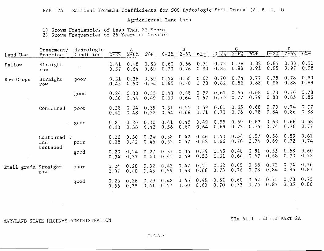
PART 2A Rational Formula Coefficients for SCS Hydrologic Soil Groups (A, B, C, D)
Agricultural Land TJs es
1) Storm Frequencies of Less Than 25 Years 2) Storm Frequencies of 25 Years or Greater
Treatment/ Hydrologic A B C D Land Use Practice Condition 0-27, 2-6% 6%+ -2- 0-2% 2-6% 6%+ -
Fallow Straight 0.41 0.48 0.53 0.60 0.66 0.71 0.72 0.78 0.82 0.84 0.88 0.91 row 0.57 0.64 0.69 0.70 0.76 0.80 0.83 0.88 0.91 0.95 0.97 0.98
Row Crops Straight row
Contoured
Contoured and terraced
small grain Straight row
poor
good
poor
good
poor
good
poor
good
WRYLAND STATE HIGHWAY ADMINISTWCI ON
I-2-A-7
SHA 61.1 - 401.0 PART 2A
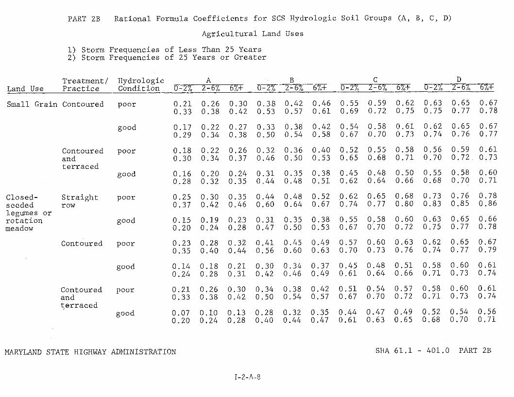
PART 2B Rational Formula Coefficients for SCS Hydrologic Soil Groups (A, B, C, D)
Agricultural Land Uses
1) Storm Frequencies of Less Than 25 Years 2) Storm Frequencies of 25 Years or Greater
Treatment/ Hydrologic A B C D Land Use Practice Condition 0-2% 2-6% 6%+ -2-6% 6%+ 0-2% 2-6% 6x4- - 6x4-
Small Grain Contoured poor 0.21 0.26 0.30 0.38 0.42 0.46 0.55 0.59 0.62 0.63 0.65 0.67 0.33 0.38 0.42 0.53 0.57 0.61 0.69 0.72 0.75 0.75 0.77 0.78
good 0.17 0.22 0.27 0.33 0.38 0.42 0.54 0.58 0.61 0.62 0.65 0.67 0.29 0.34 0.38 0.50 0.54 0.58 0.67 0.70 0.73 0.74 0.76 0.77
Contoured poor 0.18 0.22 0.26 0.32 0.36 0.40 0.52 0.55 0.58 0.56 0.59 0.61 and 0.30 0.34 0.37 0.46 0.50 0.53 0.65 0.68 0.71 0.70 0.72 0.73 terraced
good
Closed- Straight poor 0.25 0.30 0.35 0.44 0.48 0.52 0.62 0.65 0.68 0.73 0.76 0.78 seeded row 0.37 0.42 0.46 0.60 0.64 0.67 0.74 0.77 0.80 0.83 0.85 0.86 legumes or rotation meadow
good
Contoured poor 0.23 0.28 0.32 0.41 0.45 0.49 0.57 0.60 0.63 0.62 0.65 0.67 0.35 0.40 0.44 0.56 0.60 0.63 0.70 0.73 0.76 0.74 0.77 0.79
good 0.14 0.18 0.21 0.30 0.34 0.37 0.45 0.48 0.51 0.58 0.60 0.61 0.24 0.28 0.31 0.42 0.46 0.49 0.61 0.64 0.66 0.71 0.73 0.74
Contoured poor 0.21 0.26 0.30 0.34 0.38 0.42 0.51 0.54 0.57 0.58 0.60 0.61 and 0.33 0.38 0.42 0.50 0.54 0.57 0.67 0.70 0.72 0.71 0.73 0.74 qerraced
good 0.07 0.10 0.13 0.28 0.32 0.35 0.44 0.47 0.49 0.52 0.54 0.56 0.20 0.24 0.28 0.40 0.44 0.47 0.61 0.63 0.65 0.68 0.70 0.71
MARYLAND STATE HIGHWAY ADMINISTRATION SHA 61.1 - 401.0 PART 2B

PART 3 R a t i o n a l Formula C o e f f i c i e n t s f o r SCS Hydrologic S o i l Groups (A, B , C, D)
Urban Land Uses
1 ) Storm Frequencies of Less Than 25 Years 2) Storm Frequencies o f 25 Years and Greater
Treatment / Hydrologic: A B C D 6%+ j J J - 6 % 6%+ 0-2% 2-6% 6 % r 0-2% 2 - 69 Condi t ion 0-2% 2 - 64 6%+ Land Use P r a c t i c e
?aved Areas $ Impervious sur faces
)pen Space- Lawns e t c .
Cndus t r i a l
<es i d e n t a l
Lot S i z e 118 a c r e
Lot S i z e 114 a c r e
Lot S i z e 113 a c r e
Lot S i z e 112 a c r e
Lot S i z e 1 a c r e
URYLAND STATE HIGHWAY ADMINISTRATION SHA 6 1 . 1 - 401.0 PART 3

b. Time o f C o n c e n t r a t i o n - The t i m e o f c o n c e n t r a t i o n i s d e f i n e d as t h e i n t e r v a l o f t i m e r e q u i r e d f o r t h e f l o w a t t h e p o i n t o f i n v e s t i g a t i o n t o become a maximum. S ince t h e d e s i g n e r w i l l work w i t h s e v e r a l s t o r m f r e q u e n c i e s t h e compu ta t i on s h o u l d be s i m p l i f i e d by d e t e r m i n i n g t h e t i m e o f c o n c e n t r a t i o n f o r t h e 10 y e a r f requency s t o r m and u s i n g t h i s t i m e f o r a l l f r equenc ies . I n t h e case o f homogeneous d r a i n a g e areas, t h e t i m e o f c o n c e n t r a t i o n w i l l be t h e t o t a l t i m e r e q u i r e d f o r t h e r u n o f f t o f l o w f rom t h e most h y d r a u l i c a l l y remote p o i n t i n t h e d r a i n a g e area t o t h e p o i n t o f i n v e s t i g a t i o n . The same method a p p l i e s t o heterogeneous d ra inage areas t h a t have a h i g h e r "CA p ro - d u c t " i n t h e most d i s t a n t p o r t i o n s o f t h e d r a i n a g e area. However, i n t h e case o f heterogeneous d r a i n a g e areas where t h e most d i s t a n t p o r t i o n s have a 1 ower "CA p r o d u c t " t h a n t h e p o r t i o n s n e a r e s t t h e p o i n t o f i n v e s t i g a t i o n , t h a t may n o t be v a l i d . I n t h i s i n s t a n c e maximum f l o w may occu r b e f o r e runo f f f r o m t h e most d i s t a n t p o r t i o n s o f t h e d r a i n a g e area has reached t h e p o i n t o f i n v e s t i g a t i o n . When t h i s occu rs , b o t h t h e t i m e o f c o n c e n t r a t i o n and t h e d r a i n a g e a rea shou ld be reduced t o r e f l e c t t h i s c o n d i t i o n . The f l o w p a t h shou ld be c a r e f u l l y s e l e c t e d t o be r e p r e s e n t a t i v e o f t h e d ra inage area as a who1 e. F o r example, panhandle shaped d r a i n a g e areas may y i e l d e x t r e m e l y l o n g t i m e s o f c o n c e n t r a t i o n t h a t a r e n o t t y p i c a l f o r t h e watershed. It i s suggested t h a t more t h a n one p a t h be i n v e s t i g a t e d . When a t i m e o f l e s s t h a n f i v e m inu tes i s encounted, a f i v e m i n u t e d u r a t i o n w i l l be used t o de te rm ine t h e i n t e n s i t y . However, t h e a c t u a l t i m e w i l l be used t o c a l c u l a t e t h e t o t a l t i m e o f c o n c e n t r a t i o n f o r t h e watershed.
The t i m e s o f c o n c e n t r a t i o n t i c ) Ss t h e sum o f t h e t i m e inc remen ts f o r a l l t y p e s o f f l o w such as: o v e r l a n d f l o w ( t o ) , swale f l o w (t,), d i t c h f l o w ( t d ) , g u t t e r f l o w ( t g ) and p i p e f l o w ( t p ) , each i f a p p l i c a b l e . F o r "Over1 and F l ow" t h e s u r f a c e roughness c o e f f i c i e n t s and maximum a1 1 owable f l o w l e n g t h s a r e o b t a i n e d f o r m SHA-61.1-402.0 and to i s read f rom t h e nomograph SHA-61 .l-402.1. The t o t a l l e n g t h o f o v e r l a n d f l o w s h o u l d n o t exceed 400 f e e t except o v e r paved areas. It i s assumed t h a t w i t h i n t h i s d i s t a n c e some f o r m o f c o n c e n t r a t e d f l o w w i l l occur.
A l l o t h e r t i m e inc remen ts (t,, t d , tg, and t p ) a r e o b t a i n e d by e s t i - m a t i n g t h e average v e l o c i t y i n each reach and d i v i d i n g i t i n t o t h e t o t a l l e n g t h o f t h a t reach. T h i s i s done by Manning 's f o r m u l a o r t h e a p p r o p r i a t e c h a r t whenever a v a i l a b l e . F o r ts and t d t h i s i s a t r i a l and e r r o r p r o - cedure as f o l l o w s : ( r e f e r t o f i g u r e 1 )
tc 8 p o i n t A i s known A - *
Assume an average v e l o c i t y , V , i n t h e d i t c h o r swale and c a l c u l a t e tc @ p o i n t B.
Use t h i s t i m e t o compute t h e d i s c h a r g e i n t h e d i t c h . Us ing t h e appro- p r i a t e c h a r t , read t h e i nstantaneous v e l o c i t y V i . C a l c u l a t e t h e average v e l o c i t y V a by t a k i n g 75% o f V i . I f V a = V, t h e assump- t i o n i s c o r r e c t . C o n t i n u e on t o t h e n e x t s e c t i o n .
I f V a t V , Use V a as t h e n e x t assumpt ion. C o n t i n u e t h i s p rocess u n t i l V a = V.
FIG. I

RECOMMENDED "N" VALUES FOR USE WITH CHART SHA-61.1-402.1
AVERAGE "N" VALUES
RURAL AND NATURAL AREAS TYPE OF SURFACE I'N " CULTIVATED FIELDS 0.30 PASTURE OR AVERAGE GRASS 0.40 WOODS 0.60
PAVED AND DEVELOPED AREAS
TYPE OF SURFACE "N" PAVED SURFACE 0.02 COMMERCIAL OR INDUSTRIAL DEVELOPMENT 0.0 5 ACROSS AVERAGE HIGHWAY PAVEMENT AND SHOULDER
TO SURFACE DRAIN DITCH 0.10 APARTMENT DEVELOPMENT 0 . i ~ RESIDENTIAL DEVELOPMENT 0.20
THE ENTIRE OVERLAND SHEET FLOW TIME MUST BE DETERMINED BY A SINGLE COMPUTATION. IT CAN NOT BE COMPUTED IN SEGMENTS.1F MORE THAN ONE TYPE OF SURFACE IS INVOLVED IN THE FLOW PATH, COMPUTE A WEIGHTED "N" PROPORTIONAL TO THE LENGTH OF FLOW OVER EACH SURFACE.
OVERLAND FLOW LENGTH
ONERODABLE SURFACES THE MAXIMUM ALLOWABLE OVERLAND FLOW LENGTH IS 4 0 0 FEET. HOWEVER, THE DESIGNER SHOULD CONSIDER SLOPE AND SOIL TYPE BEFORE DEFIPdDNG OVERLAND F i 0 - w ~ E N G S ~ .
I
ON NON-ERODABLE SURFACES THERE IS NO LIMIT ON OVERLAND FLOW LENGTH. IT IS DETERMINED FROM CONTOURS ALONE. OVERLAND FLOW MUST NEVER BE CONTINUED BEYOND THE POINT AT WHICH PLANS OR CONTOURS INDICATE THE PRESENCE OF GUTTER, SWALE OR OTHER WATERCOURSE.
I MARYLAND STATE HIGHWAY ADMINISTRATION SHA-61.1- 402.0

I FOR RECOMMENDED VALUES OF IN' AND 'L' SEE TABLE SHA- 61.1-402.0
1 2 0 0 1000
8 0 0
6 0 0
/ /
/ /
/
EXAMPLE:
L = 100 FT.
N = 0 . 4 0
s = , I %
READ T = 13.6 MIN.
SOURCE ARTICLE BY W.S. KERBY MARCH 1959 ISSUE
OVERLAND SHEET FLOW MARYLAND STATE HIGHWAY ADMINISTRATION
SHA -61.1- 402.1 REVISED 1 - 1 - 77
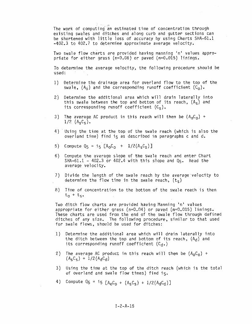
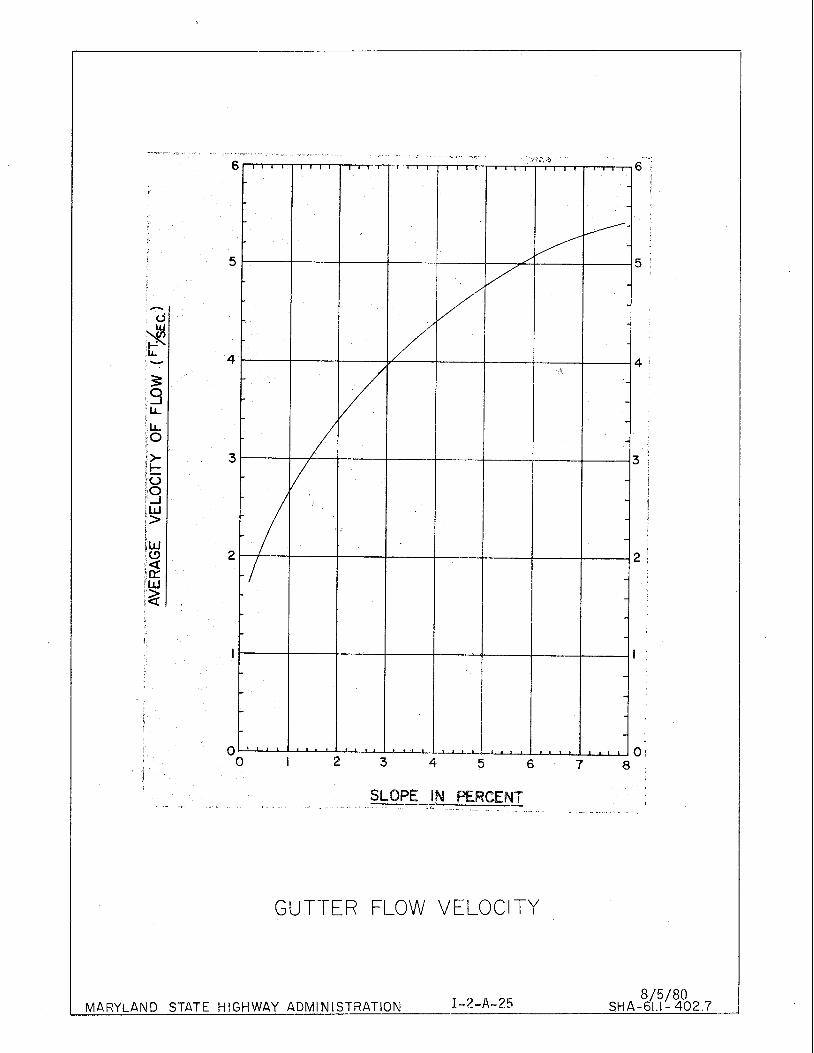
The work o f comput ing an e s t i m a t e d t i m e o f c o n c e n t r a t i o n t h r o u g h e x i s t i n g swales and d i t c h e s and a l o n g c u r b and g u t t e r s e c t i o n s can be s h o r t e n e d w i t h l i t t l e l o s s o f accuracy by u s i n g C h a r t s SHA-61.1 -402.3 t o 402.7 t o de te rm ine approx imate average v e l o c i t y .
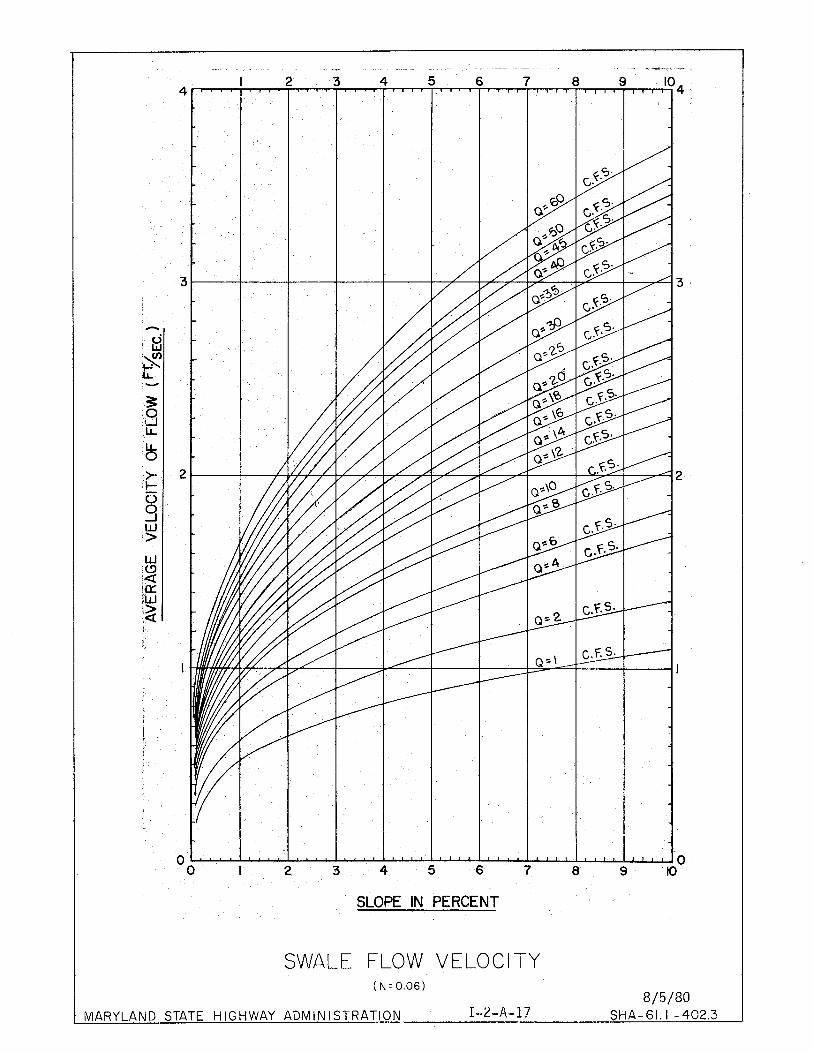
Two swal e f l o w c h a r t s a r e p r o v i d e d h a v i n g manning ' n ' va lues appro- p r i a t e f o r e i t h e r g rass (n=0.06) o r paved (n=0.015) l i n i n g s .
To de te rm ine t h e average v e l o c i t y , t h e f o l l o w i n g p rocedure s h o u l d be used:
1 ) Determine t h e d r a i n a g e area f o r o v e r l a n d f l o w t o t h e t o p of t h e swale, (Ao) and t h e c o r r e s p o n d i n g r u n o f f c o e f f i c i e n t (C,).
2 ) Determine t h e a d d i t i o n a l a rea which w i l l d r a i n l a t e r a l l y i n t o t h i s swale between t h e t o p and bo t tom o f i t s reach, (As) and i t s c o r r e s p o n d i n g r u n o f f c o e f f i c i e n t (C,).
3 ) The average AC p r o d u c t i n t h i s reach w i l l t h e n be (AoCo) + 1 / 2 (ASCS).
4 ) Us ing t h e t i m e a t t h e t o p o f t h e swale reach (wh ich i s a l s o t h e o v e r l a n d t i m e ) f i n d i 5 as d e s c r i b e d i n paragraphs c and d.
5 ) Compute Q5 = i 5 CAoCo + 1 / 2 ( A s C s ) l
6 ) Compute t h e average s l o p e o f t h e swale reach and e n t e r C h a r t SHA-61.1 - 402.3 o r 402.4 w i t h t h i s s l o p e and Q5. Read t h e average v e l o c i t y .
7 ) D i v i d e t h e l e n g t h o f t h e swale reach by t h e average v e l o c i t y t o d e t e r m i n e t h e f l o w t i m e i n t h e swale reach, (t,)
8 ) Time o f c o n c e n t r a t i o n t o t h e bo t tom o f t h e swale reach i s t h e n to + ts.
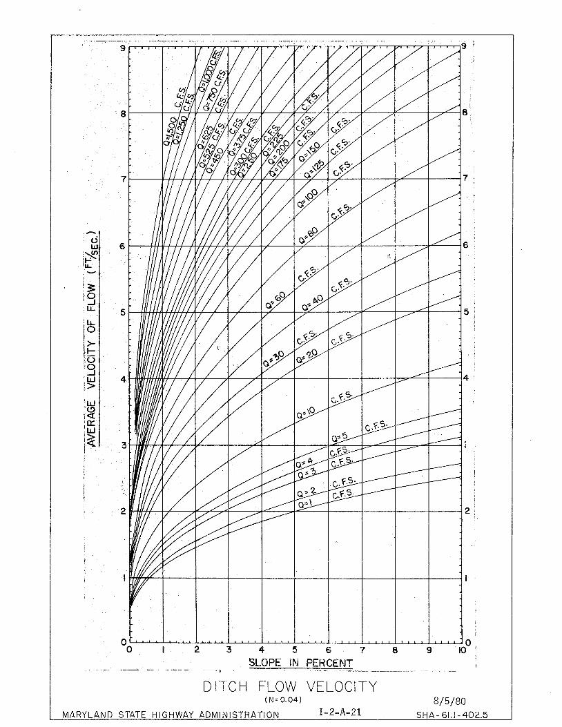
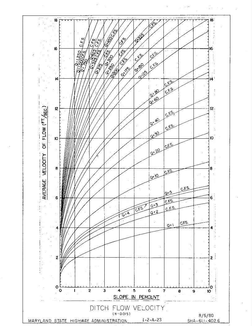
Two d i t c h f l o w c h a r t s a r e p r o v i d e d h a v i n g Manning ' n ' v a l u e s a p p r o p r i a t e f o r e i t h e r g rass (n=0.04) o r paved (n=0.015) l i n i n g s . These c h a r t s a r e used f rom t h e end o f t h e swale f l o w t h r o u g h d e f i n e d d i t c h e s o f any s i ze . The f o l l o w i n g procedure , s i m i l a r t o t h a t used f o r swale f l o w s , s h o u l d be used f o r d i t c h e s :
1 ) Determine t h e a d d i t i o n a l a r e a wh ich w i l l d r a i n l a t e r a l l y i n t o t h e d i t c h between t h e t o p and bo t tom o f i t s reach, (Ad) and i t s c o r r e s p o n d i n g r u n o f f c o e f f i c i e n t (Cd. )
2 ) The average AC p r o d u c t i n t h i s reach w i l l t h e n be (/loco) + ( AsCs ) + 1/2 ( AdCd)
3 ) U s i n g t h e t i m e a t t h e t o p o f t h e d i t c h reach (wh ich i s t h e t o t a l o f o v e r l a n d and swale f l o w t i m e s ) f i n d i 5 .
5 ) Compute t h e average s l o p e f o r t h e d i t c h reach and e n t e r C h a r t SHA-61.1 - 402.5 o r 402.6 w i t h t h i s s l o p e and Q5 and read t h e average v e l o c i t y .
When c u r b and g u t t e r f l o w forms a p a r t o f t h e f l o w path , average v e l o c i t y can be determined f rom Char t SHA-61.1 - 402.7 by e n t e r i n g t h e c h a r t w i t h t h e s t r e e t grade and r e a d i n g t h e v e l o c i t y d i r e c t l y .
The method o u t l i n e d above i s i n t e n d e d t o save work i n d e t e r m i n i n g t h e t i m e o f c o n c e n t r a t i o n t o some p o i n t o f i n v e s t i g a t i o n and no a t t e m p t s h o u l d be made t o use t h e above c h a r t s as a s u b s t i t u t e f o r Manning c h a r t s when d e s i g n i n g d i t c h e s o r swales o r e v a l u a t i n g t h e i r o p e r a t i o n s i n c e t h e y w i l l n o t supp ly i n s t a n t a n e o u s v e l o c i t y o r depth o f f low.
- - . . - - A - _
I 2 3 4 5 6 7 8 9 4 - . . , . . I , , P . 3 . r , . . . s o c I . . . , I , , 8 , I , , 1 , 1 , 1 0 4
y C.
I
I
3
h
I <j W
9 :t V
3 .O ?I l.L
% Iz 0 0 -I W > W (3 a fa Fw :> .a !
2
I
I I
!
i 1
0 0 I 2 3 4 5 6 7 8 9 10
SLOPE IN PERCENT
SWALE FLOW VELOCITY ( N = 0.06)
8/5/80 MARYLAND STATE HIGHWAY ADMINISTRATION I-2-A-17 SHA-61.1 - 402.3

9
8
7
'h
: c j W $ LL Y
3 S LL
IL 0
I>-
' I- fG i3 >
I
iY i a '(r W
.k
6
5
4
3
I 2 I
I
I 0 0 I 2 3 4 5 6 7 8 9 10
! SLOPE IN PERCENT - - -
SWALE FLOW VELOCITY ( N -0.015)
8/5/80 MARYLAND STATE HIGHWAY ADMINISTRATION I-2-A-1 9 SHA.-61.1- 4 0 2 . 4
SLOPE IN PERCENT I
1 --- - - - - - -- - - - --- - - - - -- - - - e -
DITCH FLOW VELOCITY ( ~ 2 0 . 0 4 ) 8/5/80
MARYLAND STATE HIGHWAY ADMINISTRATION I-2-A-21 SHA- GI. 1 - 402.5
-- SLOPE IN ERCENT --- -
- - . A - -- -
MARYLAN'D
DITCH FLOW VELOCITY (N=0.015) 8/5/80
STATE HIGHWAY ADMINISTRATION I-2-A-23 SHA-61.1- 4 0 2 . 6 1
SLOPE If\l PERCENT - . . .
GUTTER FLOW VELOCITY
I-2-A-25 8/5/80 MARYLAND STATE HIGHWAY ADMlN ISTRATION SHA-61.1- 402.7
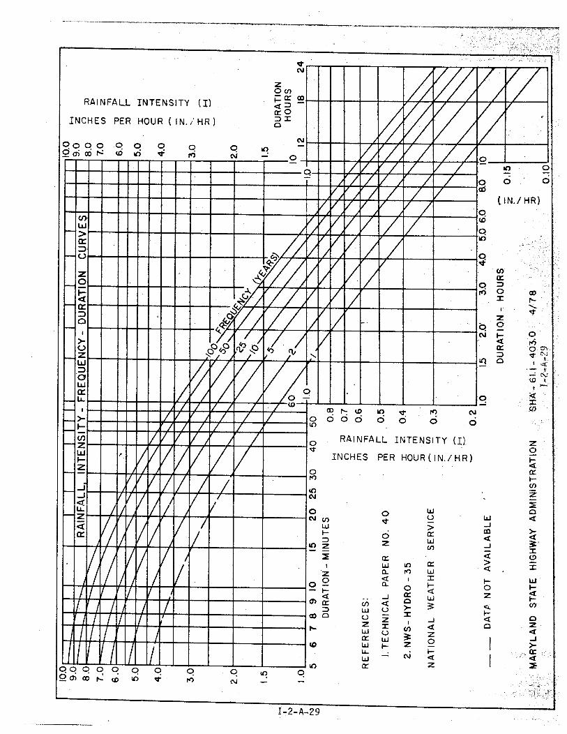
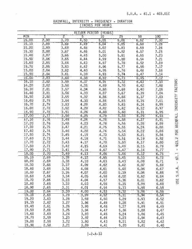
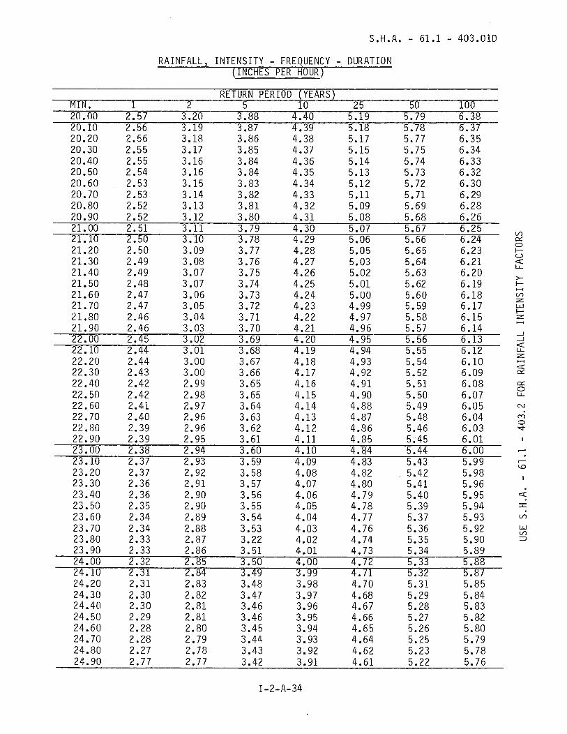
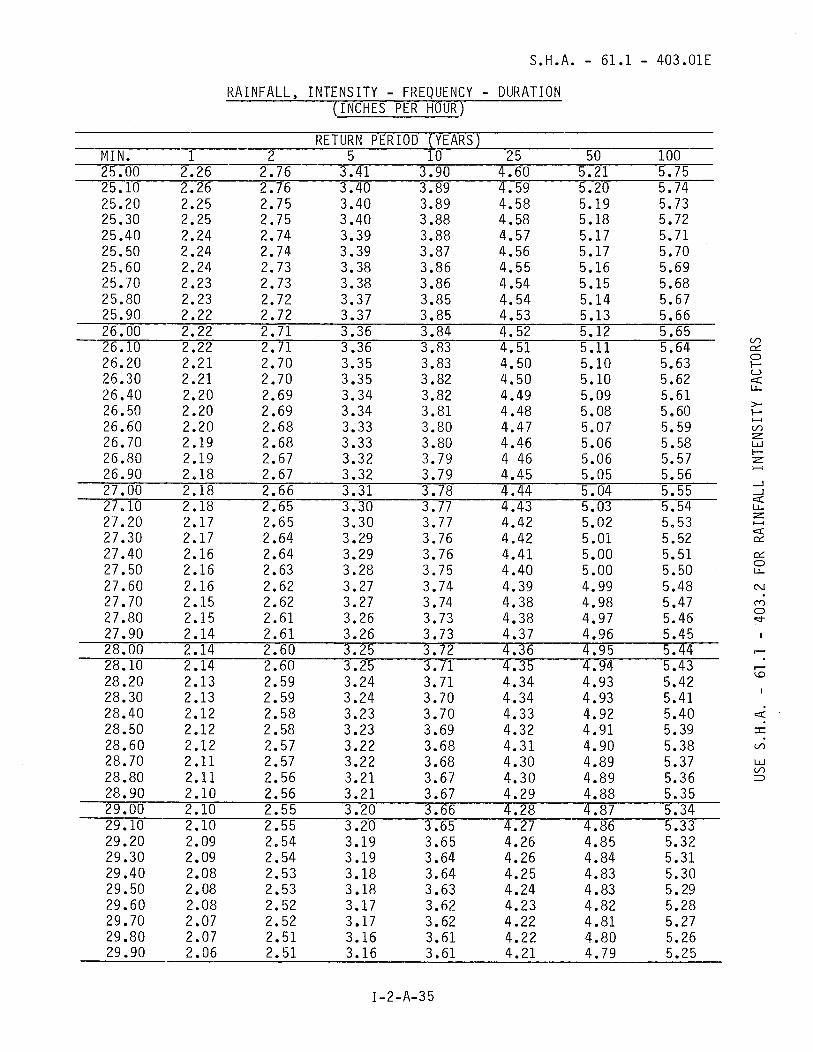
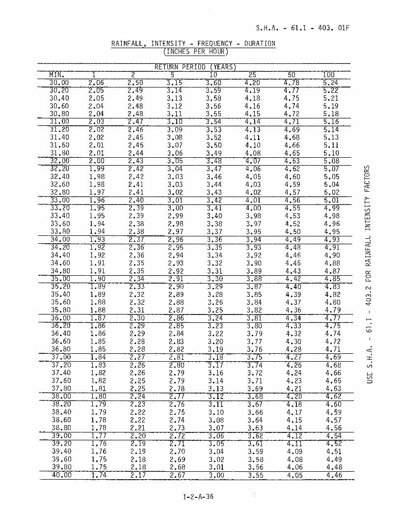
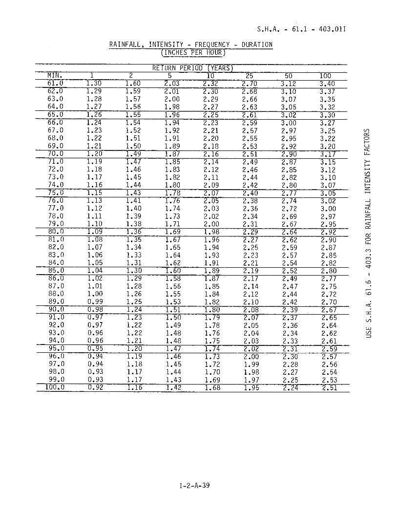
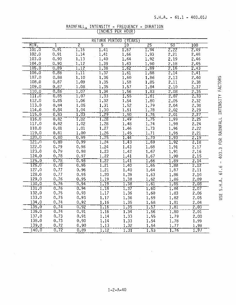
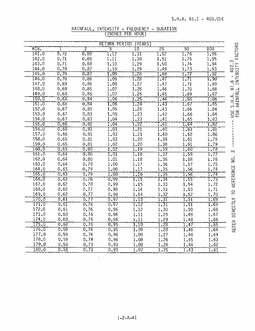
c. R a i n f a l l I n t e n s i t y - To de te rm ine t h e maximum d i s c h a r g e f rom a watershed, f o r a g i v e n s to rm f requency and d u r a t i o n , t h e d e s i g n e r shou ld use t h e r a i n f a l l i n t e n s i t y f o r wh ich t h e d r a i n a g e area w i l l y i e l d t h e g r e a t e s t peak d ischarge. T h i s i s assumed t o o c c u r when t h e d u r a t i o n o f t h e s t o r m equa ls t h e t i m e o f c o n c e n t r a t i o n . The b a s i c i n t e n s i t y f o r t h i s s to rm i s read d i r e c t l y f rom C h a r t SHA-61.1-403.0 o r f r o m Tab les SHA 61.1-403.01A t h r u K.
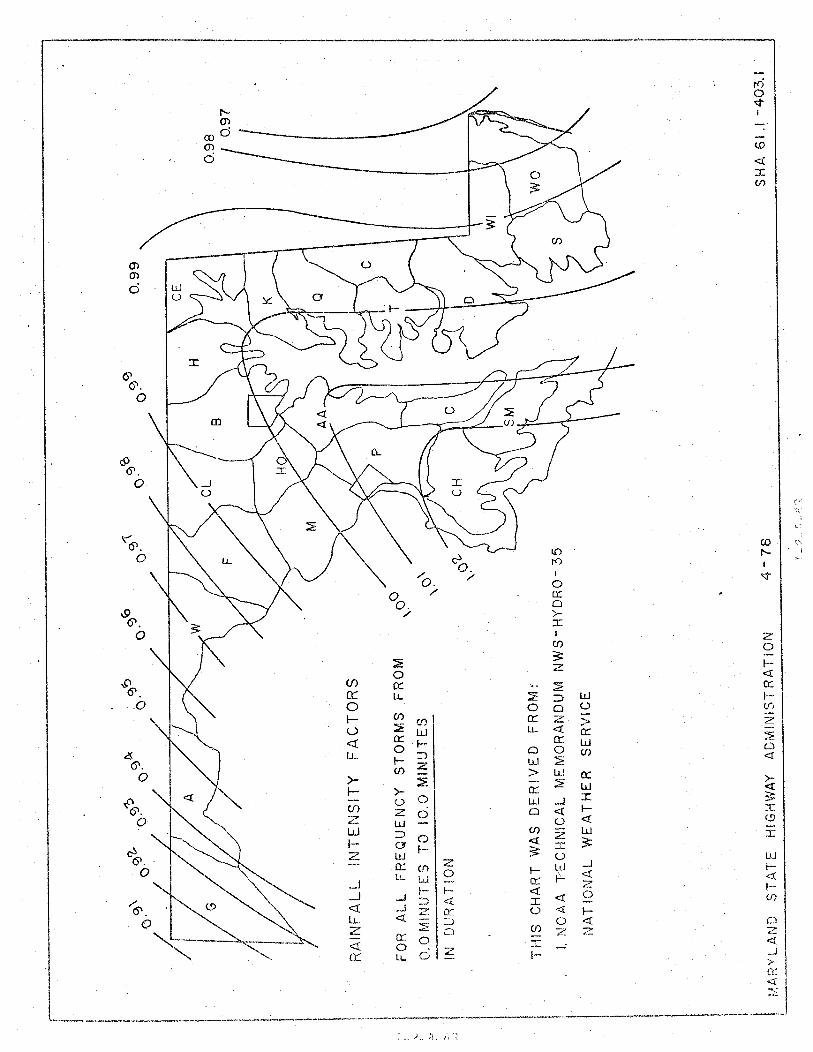
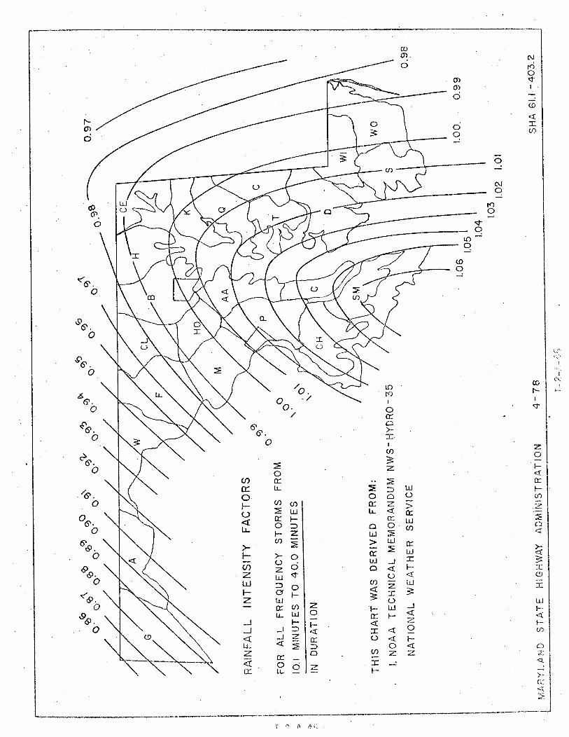
d. R a i n f a l l I n t e n s i t y C o e f f i c i e n t - Due t o t h e geograph ic e f f e c t s o f t h e Appa lach ian mountains and t h e Chesapeake Bay, r a i n f a l l i n t e n s i t y v a r i e s t h r o u g h o u t t h e s t a t e . To account f o r t h e s e e f f e c t s , t h e b a s i c i n t e n s i t y i s m o d i f i e d by a r a i n f a l l i n t e n s i t y c o e f f i c i e n t found i n t h e SHA-61.1-403 s e r i e s c h a r t s . The des ign i n t e n s i t y i s de te rm ined as f o l l ows:
Us ing t h e SHA-61.1-403.0 c h a r t w i t h a d u r a t i o n range t h a t i n c l u d e s t h e t i m e o f c o n c e n t r a t i o n , l o c a t e t h e s i t e and i n t e r - p o l a t e t h e p r o p e r i n t e n s i t y c o e f f i c i e n t . Mu1 t i p l y t h e b a s i c i n t e n s i t y f r o m C h a r t SHA 61.1 - 403.0 by t h e above f a c t o r t o o b t a i n t h e des ign i n t e n s i t y . The SHA 61.1-403 c h a r t used by t h e d e s i g n e r w i l l , o f course, change where t h e t i m e o f concen- t r a t i o n reaches 10.0 m inu tes and 40.0 m inu tes , r e s p e c t i v e l y .
e. Dra inage Area - The d r a i n a g e area c o n t r i b u t i n g r u n o f f t o t h e p o i n t o f i n v e s t i g a t i o n s h o u l d f i r s t be o u t i i n e d on a t o p o g r a p h i c map. B e f o r e making any compu ta t i ons , t h e l i m i t s o f t h e d r a i n a g e area shou ld be f i e l d checked, e s p e c i a l l y d r a i n a g e areas w i t h e x i s t i n g s t o r m sewer systems. These systems may d i v e r t r u n o f f i n t o o r away from t h e area under s tudy . A f t e r d e t e r m i n i n g t h e a c t u a l l i m i t s o f t h e watershed, t h e area must be computed i n acres.
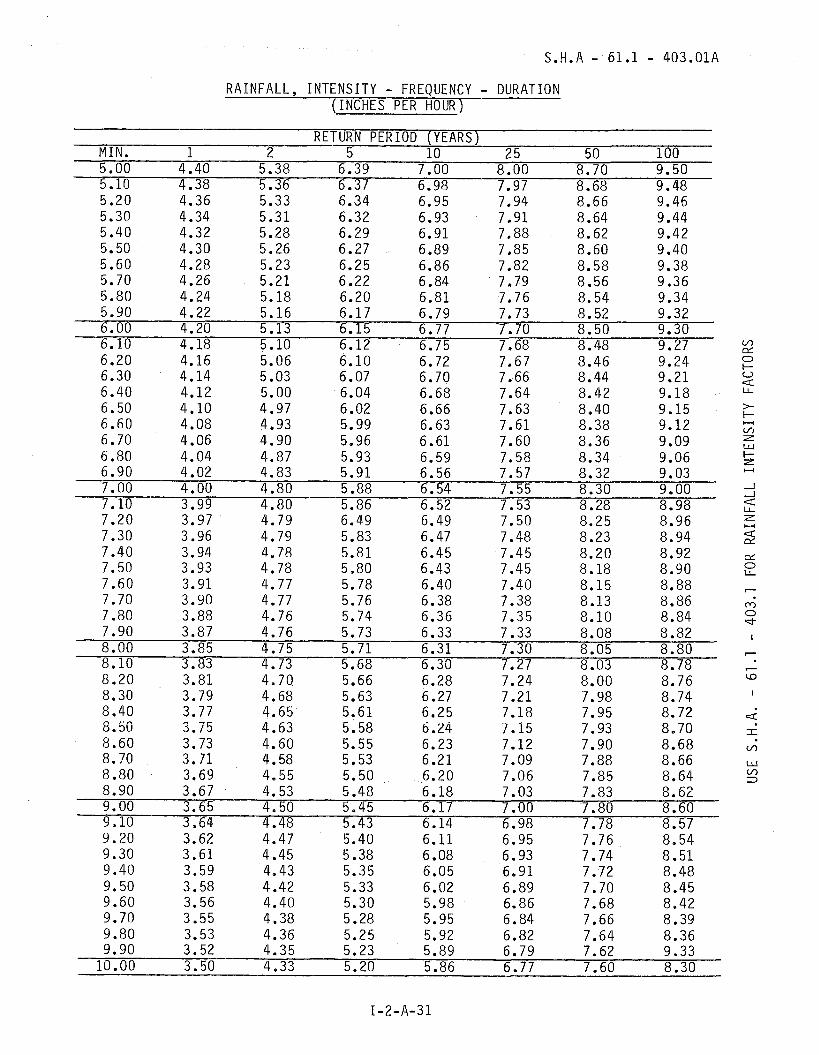
RAINFALL, INTENSITY - FREQUENCY - DURATION (INCHES PER HOUR)
RETURN PERIOD (YEARS) MIN. 1 2 5 10 2 5 50 100 5.00 4.40 5.38 6.39 7.00 8.00 8.70 9.50 5.10 4.38 5.36 6.37 6.98 7.97 8.68 9.48 5.20 4.36 5.33 6.34 6.95 7.94 8.66 9.46 5.30 4.34 5.31 6.32 6.93 7.91 8.64 9.44 5.40 4.32 5.28 6.29 6.91 7.88 8.62 9.42 5.50 4.30 5.26 6.27 6.89 7.85 8.60 9.40 5.60 4.28 5.23 6.25 6.86 7.82 8.58 9.38 5.70 4.26 5.21 6.22 6.84 7.79 8.56 9.36 5.80 4.24 5.18 6.20 6.81 7.76 8.54 9.34 5.90 4.22 5.16 6.17 6.79 7.73 8.52 9.32 6.00 4.20 5.13 6.15 6.77 7.70 8.50 9.30 6.10 4.18 5.10 6.12 6.75 7.68 8.48 9.27 6.20 4.16 5.06 6.10 6.72 7.67 8.46 9.24 6.30 4.14 5.03 6.07 6.70 7.66 8.44 9.21 6.40 4.12 5.00 6.04 6.68 7.64 8.42 9.18 6.50 4.10 4.97 6.02 6.66 7.63 8.40 9.15 6.60 4.08 4.93 5.99 6.63 7.61 8.38 9.12 6.70 4.06 4.90 5.96 6.61 7.60 8.36 9.09 6.80 4.04 4.87 5.93 6.59 7.58 8.34 9.06

S.H.A. - 61.1 - 403.018
RAINFALL, INTENSITY - FREQUENCY - DURATION (INCHES PER HOURI
RETURN PERIOD (YEARS) M I N . 1 2 5 10 2 5 50 100 10.10 3.49 4.32 5.19 5.84 6.75 7.58 8.28
RAINFALL, INTENSITY - FREQUENCY - DURATION (INCHES PER HOUR)
RETURN P E R I O D (YEARS) M I N 1 2 5 10 2 5 50 100 15.00 2.90 3.70 4.50 5.05 5.86 6.62 7.30 15.10 2.89 3.69 4.49 5.04 5.85 6.60 7.28 15.20 2.89 3.68 4.48 5.02 5.83 6.59 7.26 15.30 2.88 3.67 4.46 5.01 5.82 6.57 7.25 15.40 2.87 3.66 4.45 5.00 5.81 6.55 7.23 15.50 2.86 3.65 4.44 4.99 5.80 6.54 7.21 15.60 2.85 3.64 4.43 4.97 5.78 6.52 7.19 15.70 2.85 3.63 4.42 4.96 5.77 6.50 7.17 15.80 2.84 3.62 4.40 4.95 5.76 6.48 7.16 15.90 2.84 3.61 4.39 4.93 5.74 6.47 7.14 16.00 2.83 3.60 4.38 4.92 5.73 6.45 7.12 16.10 2.82 3.59 4.37 4.91 5.72 6.43 7.10
RAINFALL, INTENSITY - FREQUENCY - DURATION (INCHES PER HOUR)
RETURN PERIOD (YEARS) M I N . 1 2 5 10 2 5 5 0 100 20.00 2.57 3.20 3.88 4.40 5.19 5.79 6.38 20.10 2.56 3.19 3.87 4.39 5.18 5.78 6.37 20.20 2.56 3.18 3.86 4.38 5.17 5.77 6.35 20.30 2.55 3.17 3.85 4.37 5.15 5.75 6.34 20.40 2.55 3.16 3.84 4.36 5.14 5.74 6.33 20.50 2.54 3.16 3.84 4.35 5.13 5.73 6.32 20.60 2.53 3.15 3.83 4.34 5.12 5.72 6.30 20.70 2.53 3.14 3.82 4.33 5.11 5.71 6.29 20.80 2.52 3.13 3.81 4.32 5.09 5.69 6.28 20.90 2.52 3.12 3.80 4.31 5.08 5.68 6.26 21 .OO 2.51 3.11 3.79 4.30 5.07 5.67 6.25 21.10 2.50 3.10 3.78 4.29 5.06 5.66 6.24
S.H.A. - 61.1 - 403.01E
RAINFALL, INTENSITY - FREQUENCY - DURATION (INCHES PER HOUR)
RETURN PERIOD (YEARS) MIN. 1 2 5 10 2 5 5 0 100 25.00 2.26 2.76 3.41 3.90 4.60 5.21 5.75 25.10 2.26 2.76 3.40 3.89 4.59 5.20 5.74 25.20 2.25 2.75 3.40 3.89 4.58 5.19 5.73 25.30 2.25 2.75 3.40 3.88 4.58 5.18 5.72 25.40 2.24 2.74 3.39 3.88 4.57 5.17 5.71 25.50 2.24 2.74 3.39 3.87 4.56 5.17 5.70 25.60 2.24 2.73 3.38 3.86 4.55 5.16 5.69 25.70 2.23 2.73 3.38 3.86 4.54 5.15 5.68 25.80 2.23 2.72 3.37 3.85 4.54 5.14 5.67
R A I N F A L L , I N T E N S I T Y - FREQUENCY - DURATION ( INCHES PER HOUR)
RETURN PERIOD (YEARS) M I N . 1 2 5 10 2 5 50 100
M 0 Ti-

RAINFALL, INTENSITY - FREQUENCY - DURATION (INCHES PER HOURI
RETURN PERIOD (YEARS) M I N 1 2 5 10 2 5 50 100
40.00 1.74 2.17 2.67 3.00 3.55 4.05 4.46 40.20 1.73 2.16 2.66 2.99 3.54 4.04 4.45 40.40 1.73 2.15 2.65 2.98 3.53 4.02 4,43 40.60 1.72 2.14 2.64 2.97 3.52 4.01 4.42 40.80 1.72 2.14 2.63 2.96 3.51 4.00 4.41 41.00 1.71 2.13 2.62 2.96 3.50 3.99 4.39 41.20 1.70 2.12 2.61 2.95 3.49 3.97 4.38 41.40 1.70 2.11 2 .60 2.94 3.48 3.96 4.37 41.60 1.69 2.10 2.59 2.93 3.47 3.95 4.35 41.80 1.69 2.09 2.58 2.92 3.46 3.93 4.34 42.00 1.68 2.09 2.57 2.91 3.45 3.92 4.33 42.20 1.67 2.08 2.56 2.90 3.44 3.91 4.31

RAINFALL, INTENSITY - FREQUENCY - DURATION (INCHES PER HOUR)
RETURN PERIOD (YEARS) MIN. 1 2 5 10 2 5 50 100 50.2 1.47 1.85 2.29 2.62 3.12 3.54 3.88 50.4 1.46 1.85 2.29 2.62 3.11 3.53 3.87 50.6 1.46 1.84 2.28 2.61 3.10 3.52 3.86 50.8 1.46 1.84 2.27 2.60 3.09 3.51 3.85
RAINFALL, INTENSITY - FREQUENCY - DURATION (INCHES P E R HOUR)
RETURN PERIOD (YEARS) MIN. 1 2 5 10 2 5 5 0 100 61.0 1.30 1.60 2.03 2.32 2.70 3.12 3.40 62.0 1.29 1.59 2.01 2.30 2.68 3.10 3.37 63.0 1.28 1.57 2.00 2.29 2.66 3.07 3.35
S.H.A. - 61.1 - 403.015
RAINFALL, INTENSITY - FREQUENCY - DURATION (INCHES PER HOUR)
RETURN PERIOD (YEARS) M I N . 1 2 5 10 2 5 5 0 100 101 .O 0.91 1.15 1.41 1.67 1.94 2.22 2.49 102 .O 0.91 1.14 1.41 1.66 1.93 2.21 2.48 103 .O 0.90 1.13 1.40 1.64 1.92 2.19 2.46 104.0 0.90 1.12 1.39 1.63 1.90 2.18 2.45 105.0 0.89 1.12 1.38 1.62 1.89 2.16 2.43 106.0 0.88 1.11 1.37 1.61 1.88 2.14 2.41 107.0 0.88 1.10 1.36 1.60 1.86 2.13 2.40 108.0 0.87 1.09 1.35 1.58 1.85 2.11 2.38
RAINFALL, INTENSITY - FREQUENCY - DURATION (INCHES PER HOUR)
RETURN PERIOD (YEARS) MIN. 1 2 5 10 2 5 5 0 100 141.0 0.72 0.89 1.12 1.31 1.52 1.76 1.96 142 .O 0.71 0.88 1.11 1.30 1.51 1.75 1.95 143.0 0.71 0.88 1.10 1.29 1.50 1.74 1.94 144.0 0.70 0.87 1.10 1.29 1.49 1.73 1.93 145.0 0.70 0.87 1.09 1.28 1.48 1.72 1.92 146.0 0.70 0.86 1.09 1.28 1.47 1.71 1.90

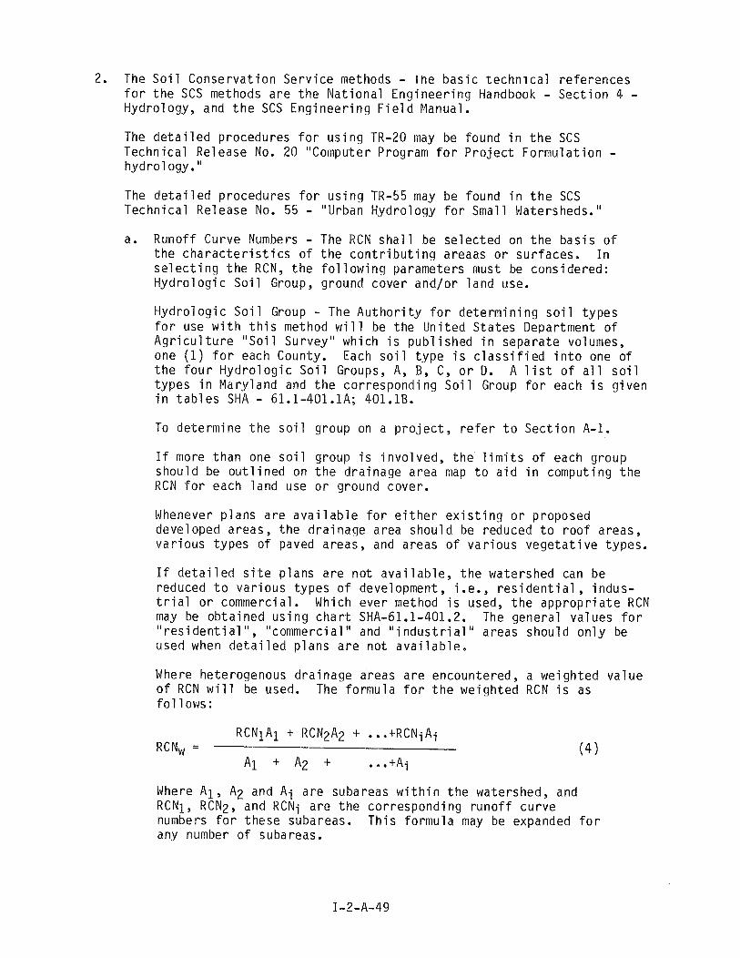
The S o i l C o n s e r v a t i o n S e r v i c e methods - i h e b a s i c t e c h n i c a l r e f e r e n c e s f o r t h e SCS methods a r e t h e N a t i o n a l E n g i n e e r i n g Handbook - S e c t i o n 4 - Hydro logy, and t h e SCS E n g i n e e r i n g F i e 1 d Manual.
The d e t a i l e d procedures f o r u s i n g TR-20 may be found i n t h e SCS Techn ica l Re lease No. 20 "Computer Program f o r P r o j e c t F o r m u l a t i o n - hydro1 ogy. "
The d e t a i l e d p rocedures f o r u s i n g TR-55 may be found i n t h e SCS T e c h n i c a l Release No. 55 - "Urban Hydro logy f o r Smal l Watersheds."
a. Runo f f Curve Numbers - The RCN s h a l l be s e l e c t e d on t h e b a s i s o f t h e c h a r a c t e r i s t i c s o f t h e c o n t r i b u t i n g areaas o r su r faces . I n s e l e c t i n g t h e RCN, t h e f o l l o w i n g parameters must be cons ide red : H y d r o l o g i c S o i l Group, ground cove r and /o r l a n d use.
H y d r o l o g i c S o i l Group - The A u t h o r i t y f o r d e t e r m i n i n g s o i l t y p e s f o r use w i t h t h i s method w i l l be t h e U n i t e d S t a t e s Department o f A g r i c u l t u r e "So i 1 Survey" wh ich i s pub1 i shed i n separa te volumes, one ( 1 ) f o r each County. Each s o i l t y p e i s c l a s s i f i e d i n t o one o f t h e f o u r H y d r o l o g i c S o i l Groups, A, B y C, o r D. A 1 i s t o f a l l s o i l t y p e s i n Mary land and t h e c o r r e s p o n d i n g S o i l Group f o r each i s g i v e n i n t a b l e s SHA - 61.1-401.1A; 401.1B.
- l o de te rm ine t h e s o i l group on a p r o j e c t , r e f e r t o S e c t i o n A-1.
I f more t h a n one s o i l group i s i n v o l v e d , t h e l i m i t s o f each group s h o u l d be o u t l i n e d on t h e d r a i n a g e a rea map t o a i d i n comput ing t h e RCN f o r each l a n d use o r ground cover.
Whenever p l a n s a r e a v a i l a b l e f o r e i t h e r e x i s t i n g o r proposed deve loped areas, t h e d r a i n a g e area s h o u l d be reduced t o r o o f a reas, v a r i o u s t y p e s o f paved areas, and areas o f v a r i o u s v e g e t a t i v e t ypes .
I f d e t a i l e d s i t e p l a n s a r e n o t a v a i l a b l e , t h e watershed can be reduced t o v a r i o u s t y p e s o f development, i .e., r e s i d e n t i a l , i n d u s - t r i a l o r commercia l . Which e v e r method i s used, t h e a p p r o p r i a t e RCN may be o b t a i n e d u s i n g c h a r t SHA-61.1-401.2. The genera l va lues f o r " r e s i d e n t i a l ", "commerc ia l " and " i n d u s t r i a l " areas s h o u l d o n l y be used when d e t a i l e d p l a n s a r e n o t a v a i l a b l e .
Where heterogenous d r a i n a g e areas a r e encountered, a w e i g h t e d v a l u e o f RCN w i l l be used. The f o r m u l a f o r t h e w e i g h t e d RCN i s as f o l 1 ows :
Where A1, A2 and A i a r e subareas w i t h i n t h e watershed, and RCNl, RCN2, and RCNi a r e t h e c o r r e s p o n d i n g r u n o f f c u r v e numbers f o r t h e s e subareas. T h i s f o r m u l a may be expanded f o r any number o f subareas.
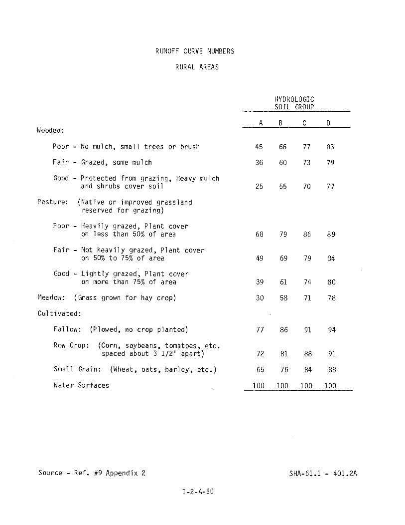
RUNOFF CURVE NUMBERS
RURAL AREAS
HYDROLOGIC SOIL GROUP
Wooded :
Poor - No mulch, sma l l t r e e s o r b rush
F a i r - Grazed, some mulch
Good - P r o t e c t e d f rom g r a z i n g , Heavy mulch and shrubs cove r s o i l
Pas tu re : ( N a t i v e o r improved g r a s s l a n d rese rved f o r g r a z i n g )
Poor - H e a v i l y grazed, P l a n t cove r on i e s s t h a n 50% o f area
F a i r - Not h e a v i l y grazed, P l a n t c o v e r on 50% t o 75% o f area
Good - L i g h t l y grazed, P l a n t c o v e r on more t h a n 75% o f area
Meadow: (Grass grown f o r hay c r o p )
C u l t i v a t e d :
F a l l o w : (Plowed, no c r o p p l a n t e d )
Row Crop: (Corn, soybeans, tomatoes, e t c . spaced about 3 112 ' a p a r t )
Smal l Gra in : (Wheat, o a t s , b a r l e y , e t c . )
Water Su r faces
Source - Ref. #9 Appendix 2

RUNOFF CURVE NUMBERS
URBAN AREAS
HYDROLOGIC SOIL GROUP
A B C D
Open Spaces, Lawns, Parks, Go1 f courses, Cemeter ies
Grass covers 75% o r more o f a rea 39 61 74 80
Grass covers 50% t o 75% o r area 49 69 79 84
Paved Areas, Roofs 98 98 98 98
S t r e e t s and Roads
Paved, Curb and G u t t e r 98 98 98 98
Hard Sur faced ( I n c l u d e s R / W ) 74 84 90 92
Gravel 76 85 89 9 1
D i r t ( I n c l u d e s R / W ) 72 82 87 89
Res i d e n t i a1 Devel opment
Row Houses o r Town Houses 80 85 90 95
118 a c r e l o t s Average 65% i m p e r v i o u s 77 85 90 92
114 a c r e l o t s Average 38% i m p e r v i o u s 61 75 83 87
113 a c r e 1 o t s Average 30% i m p e r v i o u s 57 72 8 1 86
112 a c r e l o t s Average 25% i m p e r v i o u s 54 70 80 85
1 a c r e l o t s Average 20% i m p e r v i o u s 51 68 79 84
2 a c r e l o t s 47 66 77 81
Newly Graded area, no v e g e t a t i o n 8 1 89 93 9 5
Commerci a1 and Bus iness Areas 85% i m p e r v i o u s 89 92 94 95
I n d u s t r i a1 Areas 72% i rnperv i ous 8 1 8 8 9 1 9 3
Source - Ref. # 26 Appendix 2 SHA-61.1 401.2B

b. Time o f C o n c e n t r a t i o n - When u s i n g e i t h e r t h e TR-20 o r t h e TR-55 method, t h e t i m e o f c o n c e n t r a t i o n w i l l be determined by t h e v e l o c i t y method u s i n g t h e a p p r o p r i a t e cu rve f rom c h a r t SHA-61.1.- 402.2 and Manning's Formula (See Chapter 2, S e c t i o n B-1 ) . The curves f o r over land f l o w s h a l l be used un less t h e f l o w t y p e can be d e f i n e d as a ' g r a s s waterway' o r an 'up land g u l l y ' . F o r e s t i m a t i n g f l o w t imes i n p ipes and open channels where t h e c r o s s - s e c t i o n i s known, Manning's Formula shou ld be used assuming f u l l f l o w i n p i p e s and b a n k - f u l l f l o w i n channels.
c. R a i n f a l l Data - The des ign r a i n f a l l f o r t h e SCS methods i s t h e 24 hour s torm . The r e q u i r e d irnput i s t h e r a i n f a l l depth i n inches f o r t h e d e s i r e d r e t u r n f requency and t h e geographic l o c a t i o n o f t h e watershed. T h i s d a t a may be ob ta ined f rom Char ts SHA 61.1 - 403.4 t h r u 403.9.
d. Drainage on t h e Eas te rn Shore - When comput ing r u n o f f hydrographs f o r d ra inage areas on t h e eas te rn shore ( u s i n g TR-20) t h e 24-hour Dimens ion less U n i t Hydrograph f o r use on t h e DELMARVA Pen insu la shou ld be used. T h i s da ta i s found on Table SHA-61.1 - 403.99.

VELOCITIES FOR UPLAND METHOD OF ESTIMATING Tc
MARYLAND STATE HIGHWAY ADMINISTRATION 8 / 5 / 8 0 SHA-61.1- . . 4 0 2 . 2
I - 2 - A - 5 3
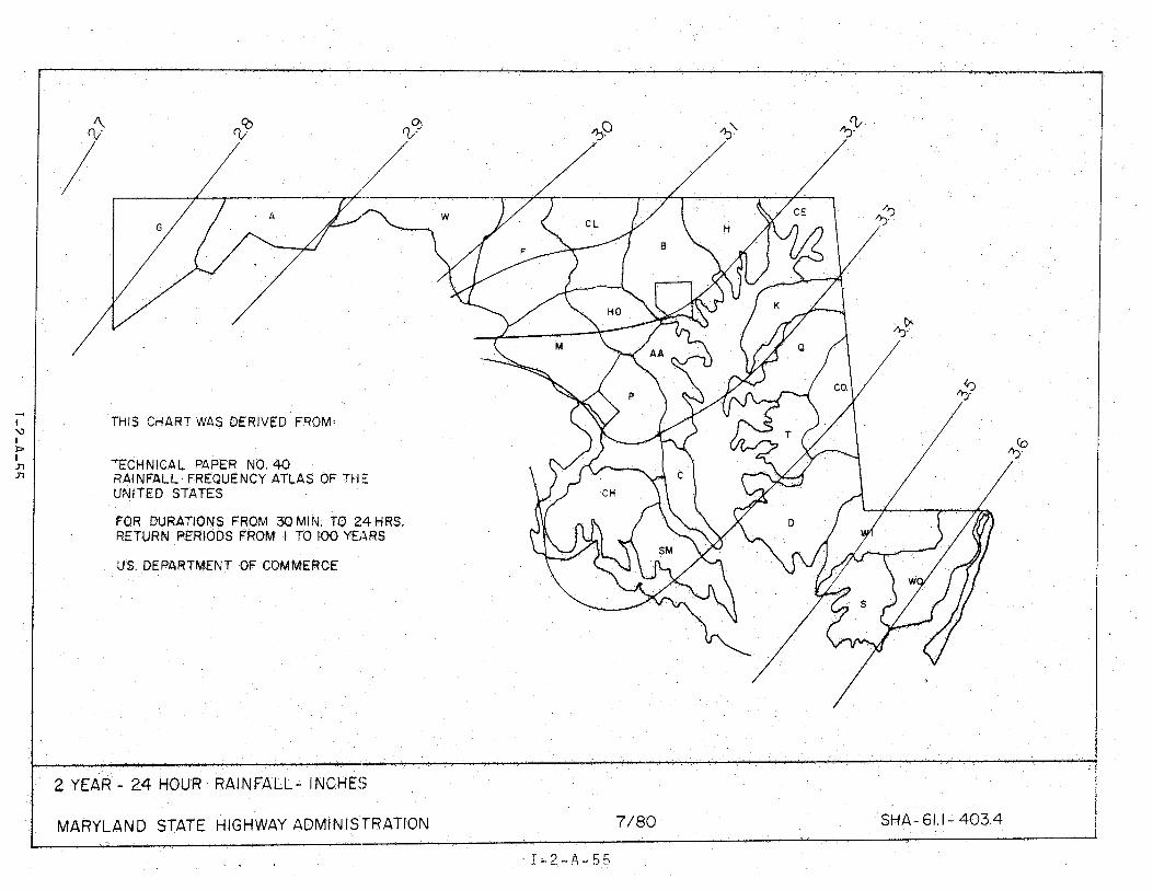
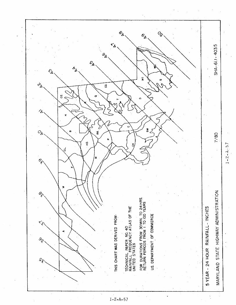


25 YEAR- 24 HOUR RAINFALL- INCHIZS
MARYLAND STATE HIGHWAY ADMINI S'TRAT.ION ~. 7 / 80 SHA- 61. I - 403.7 i
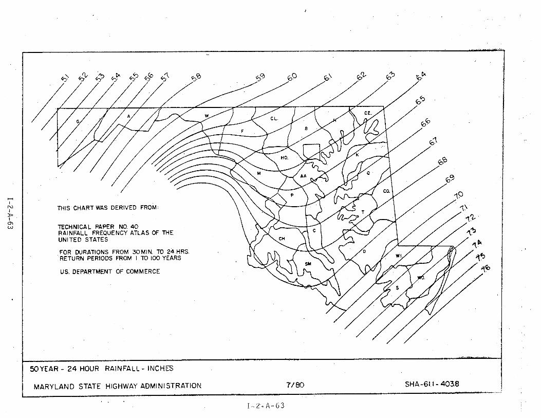
J
SOYEAR - 24 HOUR RAINFALL - INCHkT
MARY LAND STATE HIGHWAY ADMINISTRATION 71 80 SHA-611- 403.8
. . I - 2 - A - 6 3

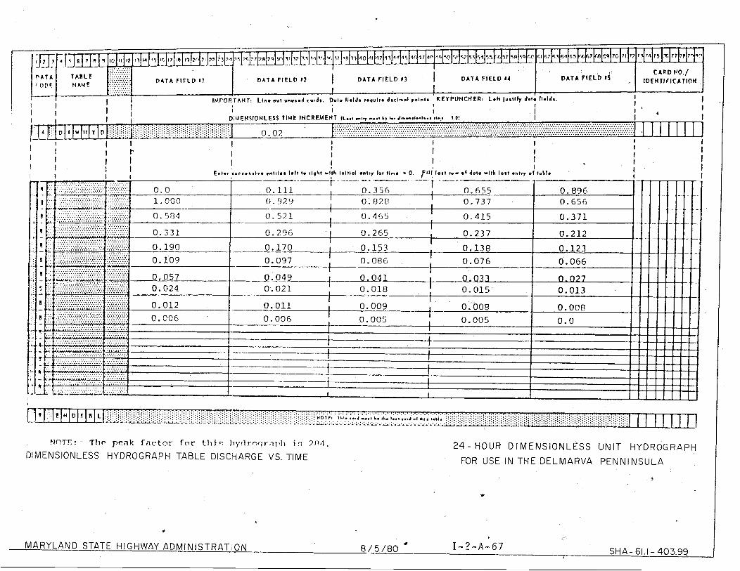
, . C A R D VO./
DATA F I E L D I 1 / D A T A F I E L D 11 D A T A FIELD I S ' IDEMTIFICATIOM I
KEYPUMCHER: Lwh lustily data Il.lds. I 1 I I I t i I I I I I I I I
I I D'IMENSIOHLESS TIME INCREMENT (L.., ,vV nr .~ be kr ~ - m * t r - l s . t 11m; 1.01 I ....................._._.........._...................................................................................................
I .................................................................................................................................... ..................................................................................................................................... ..................................................................................................................................... 0.02 ....................................................................................................................................... 1 1 1 1 1 1 .....................................................................................................................................
1 I I I I I i I I
Enter a u c t . . ~ ~ v . rntr1.s 1.11 te tIqht r l t h lnltfal ontry lor tin. * 0. J t l l loat t v r sf dsto r l t h lost .ntv e l toblr
FJO'TT:! T11p p e a k f a c t o r for t i l i r : t i y c l r o f ! r n ~ l t l i n 71111.
DIMENSIONLESS HYDROGRAPH TABLE DISCHARGE VS. TIME 2 4 - HOUR D IMENSIONLESS UNIT HYDROGRAPH
FOR USE IN THE DELMARVA PENNINSULA
MARYLAND STATE HIGHWAY ADMlNlSTRATliON 8 / 5 /80 Q I - 2 - A - 6 7 SHA- 61.1 - 403.99

e. TR-20 I n p u t Data - The TR-20 Users Manual s h o u l d be c o n s u l t e d f o r each p r o j e c t . However, t h e f o l l o w i n g i s o f f e r e d as an o r d e r o f p rocedure f o r c o l l e c t i n g t h e da ta needed t o complete t h e "Standard C o n t r o l ", " S t r u c t u r e Data" and "Stream Cross S e c t i o n " Data Forms.
GENERAL
1. D e l i n e a t e t h e o v e r a l l d r a i n a g e area t o t h e p o i n t o f i n v e s t i g a t i o n and t h e subarea t o each p o i n t a t wh ich a program s u b r o u t i n g w i l l be performed.
2. Ass ign an i d e n t i f y i n g number t o each c r o s s p o i n t a t wh ich a s u b r o u t i n e may be performed. Numbers may be 001 t o 120.
3. Ass ign an i d e n t i f y i n g number t o each s t r u c t u r e a t wh ich t h e "RESVOR" s u b r o u t i n e may be performed. Numbers may be f r o m 01 t o 60.
STANDARD CONTROL SHA-61.1 - 484
1. "RUNOFF" - Determine t h e area i n square m i l e s t o f o u r decimal p laces. Compute t h e w e i g h t e d r u n o f f c u r v e number f o r a n t e c e n t m o i s t u r e c o n d i t i o n I 1 c o n s i d e r i n g s o i l t ype , l a n d use and/or ground cover. Compute t h e t i m e o f c o n c e n t r a t i o n i n hours t o f o u r decimal p laces.
2. "RESVOR" - Determine t h e i n v e r t e l e v a t i o n o f s t r u c t u r e .
3. "REACH" - Reach i s i d e n t i f i e d by t h e number o f c r o s s s e c t i o n a t t h e l o w e r end. Length o f reach i s de te rm ied by su rvey o r s c a l e d f r o m maps o r p lans .
STRUCTURE DATA SHA-61.1 - 480
F o r each s t r u c t u r e a t wh ich a "RESVOR" s u b r o u t i n e w i l l be per formed, compute t h e d i s c h a r g e f o r v a r i o u s e l e v a t i o n s o f headwater and t h e s t o r a g e a t each o f t h e s e e l e v a t i o n s . A maximum o f t w e n t y e l e v a t i o n s can be used. The range shou ld be fo rm t h e i n v e r t e l e v a t i o n t h r o u g h t h e maximum headwater a t wh ich t h e s t r u c t u r e can be expected t o opera te . The e l e v a t i o n i n c r e - ments need n o t be u n i f o r m and s h o u l d i n c l u d e t h o s e e l e v a t i o n s a t wh ich some d e f i n i t e change t a k e s p l a c e i n t h e s t r u c t u r e o p e r a t i o n o r t h e shape o f t h e s t o r a g e area. D ischarge t h r o u g h c u l v e r t s s h o u l d c o n s i d e r i n 1 e t c o n t r o l and o u t l e t c o n t r o l . Wei r f l o w , i f p r e s e n t , shou ld be i nc luded . Cul v e r t d i s c h a r g e f o r e n t r a n c e c o n t r o l s h o u l d be de te rm ined f r o m t h e a p p r o p r i a t e e n t r a n c e c o n t r o l nomograph when a v a i l a b l e o r approx imated u s i n g f o r m u l a #7 g i v e n i n Chapter 2, S e c t i o n B-3. C u l v e r t d i s c h a r g e f o r o u t l e t c o n t r o l shou ld be computed u s i n g fo rmu las #8 and #9 g i v e n i n Chapter 2, S e c t i o n B-4. Weir f l o w i s computed by f o r m u l a #16 Chap te r 5, S e c t i o n C. D i scharges a r e expressed i n c u b i c f e e t p e r second.
S to rage inc remen ts s h o u l d be computed f rom c o n t o u r s u s i n g t h e p r o d u c t o f average wa te r s u r f a c e and depth. The s t o r a g e volume i s expressed i n a c r e - f e e t .
STREAM CROSS SECTION DATA SHA-61.1 - 481
I f t h e c r o s s s e c t i o n p o i n t s have been p r o p e r l y l o c a t e d , a t y p i c a l channel o r d i t c h may be s e l e c t e d wh ich i s r e p r e s e n t a t i v e i s t h e n a t u r a l o r a r t i f i c a l channel reach above t h e d e s i g n a t e d c r o s s s e c t i o n p o i n t t o wh ich a "REACH" s u b r o u t i n e wi 11 be performed. Compute t h e channel d i scharge a t v a r i o u s w a t e r s u r f a c e e l e v a t i o n s a t t h e " t y p i c a l " l o c a t i o n . The range shou ld be f r o m t h e i n v e r t e l e v a t i o n t o t h e maximum w a t e r s u r f a c e e l e v a t i o n wh ich i s expected t o be encountered. A maximum o f t w e n t y e l e v a t i o n s may be used b u t t h e increment between e l e v a t i o n s need n o t be un i fo rm. E l e v a t i o n s s h o u l d be i n c l u d e d where breaks i n t h e c r o s s s l o p e s occur . D ischarges may be t a k e n f r o m a Manning d i t c h c h a r t , i f a s u i t a b l e one i s a v a i l a b l e , o r computed f rom t h e Manning Formula. See f o r m u l a #5 as g i v e n Chapter 2, S e c t i o n B. The d i s c h a r g e s h o u l d be exp ressed i n c u b i c f e e t p e r second.
The area o f t h e c r o s s s e c t i o n o f t h e w a t e r a t t h e v a r i o u s e l e v a t i o n s s h o u l d be computed by s i m p l e geometry and s t a t e d i n square f e e t .
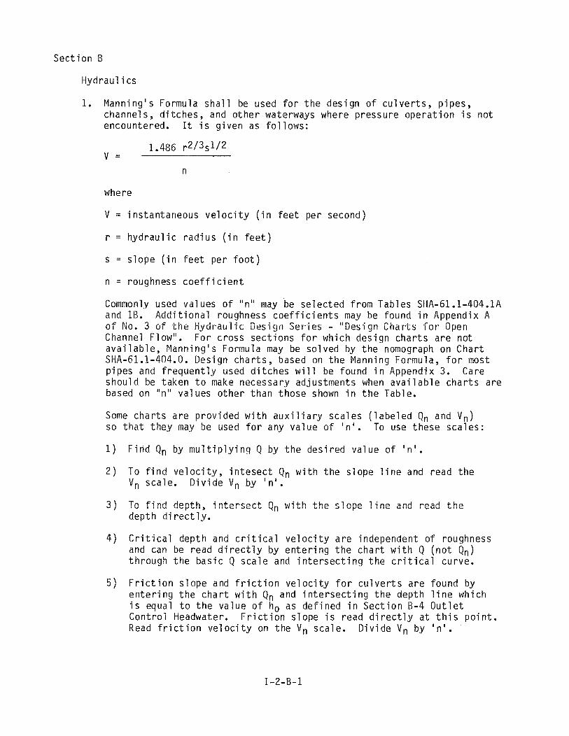
S e c t i o n B
Hydrau l i cs
1. Manning 's Formula s h a l l be used f o r t h e d e s i g n o f c u l v e r t s , p i p e s , channe ls , d i t c h e s , and o t h e r waterways where p r e s s u r e o p e r a t i o n i s n o t encountered. It i s g i v e n as f o l l o w s :
where
V = i n s t a n t a n e o u s v e l o c i t y ( i n f e e t p e r second)
r = h y d r a u l i c r a d i u s ( i n f e e t )
s = s l o p e ( i n f e e t p e r f o o t )
n = roughness c o e f f i c i e n t
Commonly used v a l ues o f " n u may be s e l e c t e d f r o m Tab1 es SHA-61 .l-404.1A and 1B. A d d i t i o n a l roughness c o e f f i c i e n t s may be found i n Appendix A o f No. 3 o f t h e l i yd ra i l i f c D e s i g n S e r i e s - "Des ign C h a r t s f o r Open Channel F low" . F o r c r o s s s e c t i o n s f o r wh ich d e s i g n c h a r t s a r e n o t a v a i l a b l e , Mann ing ' s Formula may be s o l v e d by t h e nomograph on C h a r t SHA-61.1-404.0. Des ign c h a r t s , based on t h e Manning Formula, f o r most p i p e s and f r e q u e n t l y used d i t c h e s w i l l be found i n Appendix 3. Care s h o u l d be t a k e n t o make necessa ry ad jus tmen ts when a v a i l a b l e c h a r t s a r e based on "n " v a l u e s o t h e r t h a n t h o s e shown i n t h e Table.
Some c h a r t s a r e p r o v i d e d w i t h a u x i l i a r y s c a l e s ( l a b e l e d Qn and Vn) so t h a t t h e y may be used f o r any v a l u e o f I n ' . To use t h e s e s c a l e s :
1 ) F i n d Qn by m u l t i p l y i n g Q by t h e d e s i r e d v a l u e o f I n ' .
2 ) To f i n d v e l o c i t y , i n t e s e c t Qn w i t h t h e s l o p e l i n e and r e a d t h e V n sca le . D i v i d e V n by ' n ' .
3 ) Tc f i n d depth, i n t e r s e c t Qn w i t h t h e s l ~ p e l i n e and read t h e d e p t h d i r e c t l y .
4 ) C r i t i c a l dep th and c r i t i c a l v e l o c i t y a r e independent o f roughness and can be read d i r e c t l y by e n t e r i n g t h e c h a r t w i t h Q ( n o t Qn) t h r o u g h t h e b a s i c Q s c a l e and i n t e r s e c t i n g t h e c r i t i c a l curve.
5 ) F r i c t i o n s l o p e and f r i c t i o n v e l o c i t y f o r c u l v e r t s a r e found by e n t e r i n g t h e c h a r t w i t h Qn and i n t e r s e c t i n g t h e dep th l i n e wh ich i s equal t o t h e v a l u e o f t i o as d e f i n e d i n S e c t i o n B-4 O u t l e t C o n t r o l Headwater. F r i c t i o n s l o p e i s read d i r e c t l y a t t h i s p o i n t . Read f r i c t i o n v e l o c i t y on t h e V n sca le . D i v i d e V n by I n ' .
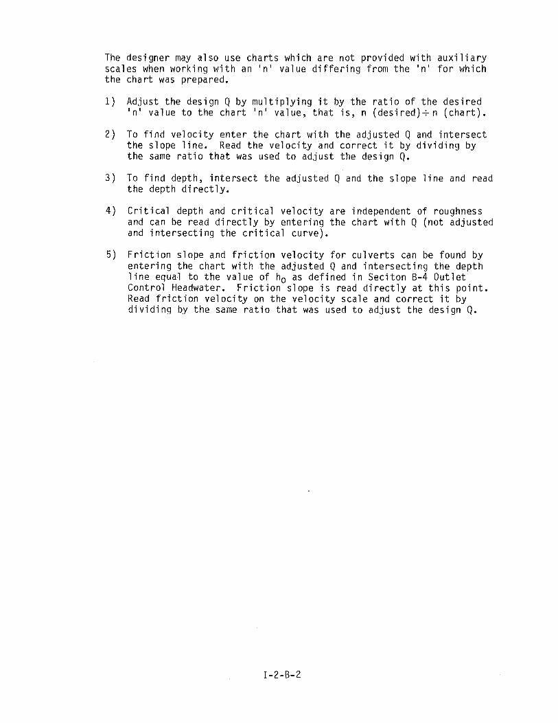
The des igner may a l s o use c h a r t s which a re no t p rov ided w i t h a u x i l i a r y sca les when work ing w i t h an I n ' va lue d i f f e r i n g f rom t h e I n ' f o r which t h e c h a r t was prepared.
1) Adjus t t h e des ign Q by m u l t i p l y i n g i t by t h e r a t i o o f t h e d e s i r e d I n ' va lue t o t h e c h a r t ' n ' va lue, t h a t i s , n ( d e s i r e d ) + n ( c h a r t ) .
2 ) To f i n d v e l o c i t y e n t e r t h e c h a r t w i t h t h e ad jus ted Q and i n t e r s e c t t h e s lope l i n e . Read t h e v e l o c i t y and c o r r e c t i t by d i v i d i n g by t h e same r a t i o t h a t was used t o a d j u s t t he des ign Q.
3 ) To f i n d depth, i n t e r s e c t t h e ad jus ted Q and t h e s lope l i n e and read t h e depth d i r e c t l y .
4 ) C r i t i c a l depth and c r i t i c a l v e l o c i t y a re independent o f roughness and can be read d i r e c t l y by e n t e r i n g t h e c h a r t w i t h Q ( no t ad jus ted and i n t e r s e c t i n g t h e c r i t i c a l curve) .
5 ) F r i c t i o n s lope and f r i c t i o n v e l o c i t y f o r c u l v e r t s can be found by e n t e r i n g t h e c h a r t w i t h t h e ad jus ted Q and i n t e r s e c t i n g t h e depth l i n e equal t o t h e va lue o f ho as de f i ned i n Sec i t on B-4 O u t l e t Con t ro l Headwater. F r i c t i o n s lope i s read d i r e c t l y a t t h i s p o i n t . Read f r i c t i o n v e l o c i t y on t h e v e l o c i t y sca le and c o r r e c t i t by d i v i d i n g by t h e same r a t i o t h a t was used t o a d j u s t t he des ign Q.
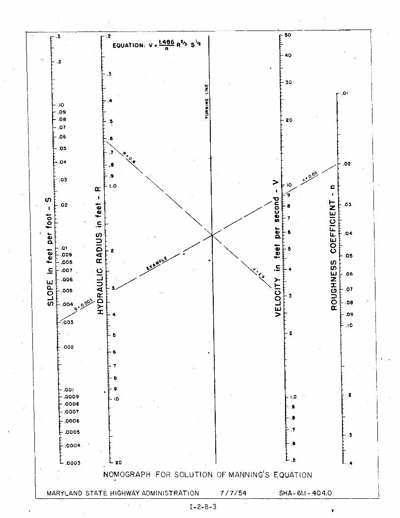
I ' NOMOGRAPH FOR SOLUTION OF MANNING'S EQUATION i ( MARYLAND STATE HIGHWAY ADMlNiSTRATI ON
i 7 / 7/54 SHA- 61.1 - 404.0 1.
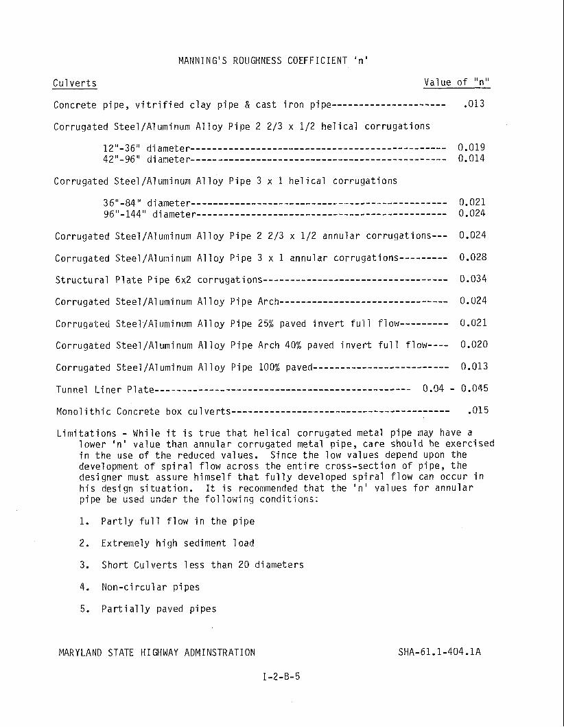
MANNING'S ROUGHNESS COEFFICIENT ' n '
C u l v e r t s Value o f "nu
Concrete p ipe, v i t r i f i e d c l a y p i pe 8 cas t i r o n pipe--------- - - - - - - - - - - - - .013
Corrugated S tee l /A l uminum A1 l o y P ipe 2 213 x 1/2 he1 i c a l c o r r u g a t i o n s
Corrugated S tee l /A1 uminum ~l l o y P ipe 3 x 1 he1 i c a l co r ruga t i ons
Corrugated Steel/Aluminum A l l o y P ipe 2 213 x 112 annular co r ruga t i ons - - - 0.024
Corrugated Steel/Aluminum A l l o y P ipe 3 x 1 annular cor rugat ions- - - - - - - - - 0.028
S t r u c t u r a l P l a t e P i p e 6x2 corrugat ions-------- - - - - - - - - - - - - - - - - - - - - - - - - - - 0.034
Corrugated Steel/Aluminum A l l o y P ipe Arch------------------------------- 0.024
Corrugated S tee i /A i umi num A1 i o y P ipe 25% paved i n v e r t f u i i f low-- - - - - - - - 0.021
Corrugated S tee l /A1 umi num A1 1 oy P ipe Arch 40% paved i n v e r t f u l l f 1 ow---- 0.020
Corrugated Steel/Aluminum A l l o y P ipe 100% paved------------------------- 0.013
L i m i t a t i o n s - Whi le i t i s t r u e t h a t he1 i c a l co r ruga ted metal p i p e may have a l owe r I n ' va l ue than annu la r co r ruga ted metal p i pe , ca re shou ld he exe rc i sed i n t h e use o f t h e reduced values. Since t h e low values depend upon t h e development o f s p i r a l f l o w across t he e n t i r e c ross - sec t i on o f p ipe , t h e des igner must assure h i m s e l f t h a t f u l l y developed s p i r a l f l o w can occur i n h i s design s i t u a t i o n . It i s recommended t h a t t h e ' n ' va lues f o r annu la r p i p e be used undzr t h e f o l low1 ng c o n d i t i o n s ;
1. P a r t l y f u l l f l o w i n t h e p i p e
2. Extremely h i g h sediment l o a d
3. Shor t C u l v e r t s l ess than 20 d iameters
4. Non-ci r c u l a r p ipes
5. P a r t i a l l y paved p ipes
MARYLAND STATE HIGHWAY ADMINSTRATION
I-2-B-5

Gut te rs , D i t c h e s and Channels Va lue o f " n "
Concrete o r b i tuminous l i n e d channels .................................. 0.013
B i tuminous concre te pav ing w i t h concre te gut ter - - - - - - - - - - - - - - - - - - - - - - - - - 0.015
Grass g u t t e r s & d i t c h e s , f l o w g r e a t e r t h a n 6" - - - - - - - - - - - - - - - - - - - - - - - - - - - .040
Grass g u t t e r s & d i t c h e s , f l o w l e s s than 6" - - - - - - - - - - - - - - - - - - - - - - - - - - - - - - .060
Gahions----------------------------------------------------------------- 0.030
Rip-Rap------------------------------------------ Ref. t o Char t SHA-61.1-405.1
Channels no t main ta ined, uncut weeds & brush----- - - - - - - - - - - - - - - - - - - - .08 - -12
E a r t h g u t t e r s and di tches----- - - - - - - - - - - - - - - - - - - - - - - - - - - - - - - - - - - - - - - - - - - .025
D i t c h e s i n rock----- - - - - - - - - - - - - - - - - - - - - - - - - - - - - - - - - - - - - - - - - - - - - - - - - - - - - .037
Seed and Mu1 ch---------------------------------------------------------- .030
S o i l S t a b i l i z a t i o n Matt ing----- - - - - - - - - - - - - - - - - - - - - - - - - - - - - - - - - - - - - - - - - - .030
N a t u r a l Stream channels-- - - - - - - - - - - - - - - - - - - - - - - - - - - - - - - - - - - - - - - - - - .035 - . I50
MARYLAND STATE HIGHWAY ADMINISTRATION
I-2-B-6
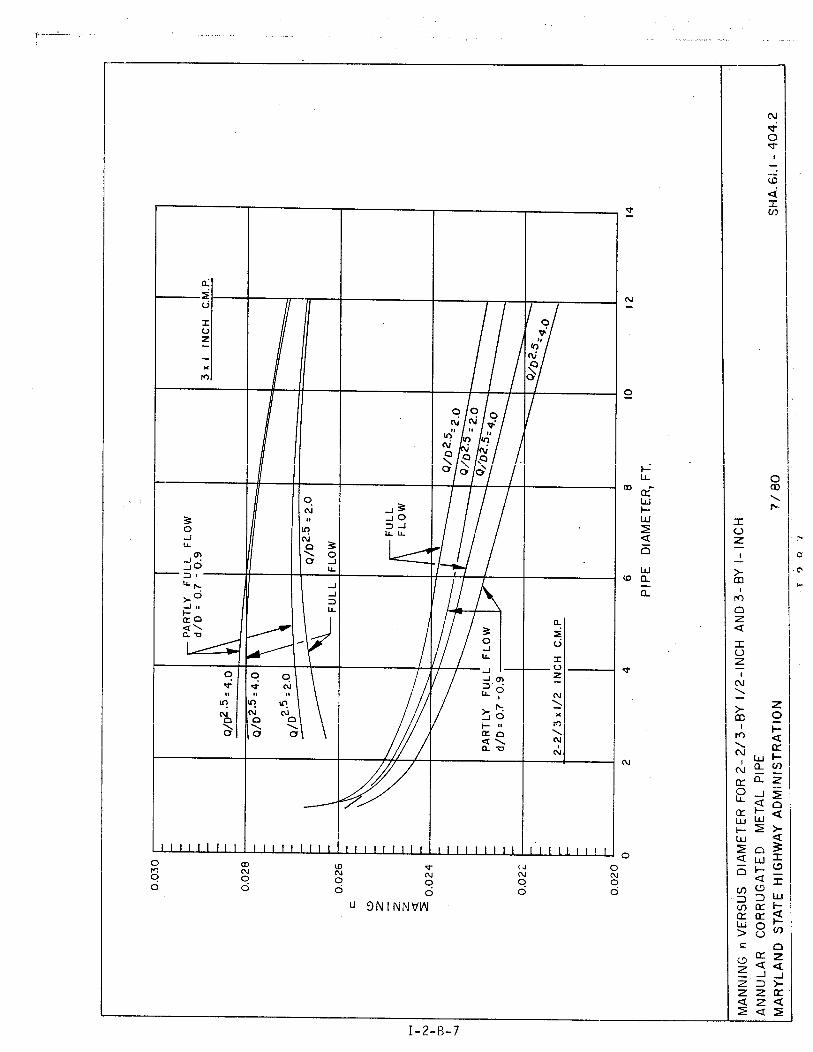


Th+e - C ~ a t i nutty -EquaQilcsn ,a- This eq,uati%crn expresses ,a relat ionship w h i c h i s vaf i d for .t&e *$I-sw :at any poi-nt in .any open ,charmel., cu lve r t , or
:pi p,e Yincl ud i n,g -those .ope~,at i nq under pressuse.
T h e qequat %an i.s g i ven as s f 0 1 1 ews :
Q A + -the r.ata .of. f l o w a t thG point rrf invest iqatirsn ( i n ..cub1 e fwt per ,second)
V + I-nstantan.@ous v~!Iocfty ( i n fee t per'secsnd)
A P crosg s,ectiona'l area .sf -the water ( i n square f e e t )
3, Ent ~ a n c e Cant POI Headwater
badwa",er d i s,&aq$ re1 at isnships T'or- the various types o f ei pcular, el 1 S ptisa1 and p i p ~ ~ a f c k " C U ~ V B P ~ S *flawi n q under entrance ( i n l e t con- t rol ) $ p a zha.5ed can lakora$~.r:y q ? % ~ a r $ k wi t h node? '; and v e ~ V f i a d 7 n sone i.nq.t;anee.s by protcrtype t e s t s . The% research data were analyzed and -nmaqrqphs fo r ds%errni.n+rq culvert capacity fo-r iwlet conerol were developed by the D i vi s i , ~ n o f h'yrir.ograpfiic Research, Btr ~ e a u o f T u b 1 j c Roads, ( see C h a ~ t SH'A-tib,"I - 4%0), CJh-en nonographs d r s not avai lable for the. cu1 vert under investiqats'on, t h e hggdwater depth ne,quired t o discharge a qiu'en f l o w u n d w entrance j i n l e t ) control operstioq may be aprrroxiivated by 'the Fol f owing procedure:
H\*I = the headwater d e p t h a t the upsttean end o f the pipe ( i n f e e t )
d, = Yormal depth ( i n f e e t )
K, = the entrsnce loss coeff icient
V, = n~rmal * /@loc i t$ ( i n fee t per second)
q = acceleration d u e to gravity ( i n f & e t per secand., per second)
I f the slope o f the culvert i s qreater t h a n c r i t i c a l slope use Ac ( q ~ j t i c d f depth) instead of d n a n d 'Jc ( c r i t i c a l veloci ty) instead of V,. ( S A ~ Appendix I I reference W22a). The value of the entrance loss coef f ic ien t ( K , ) for use i n t h i s equation shall be taken from Tab1 q . S M A p 6 1 ,1 - 4US,O,
. I
I-2-8-ll
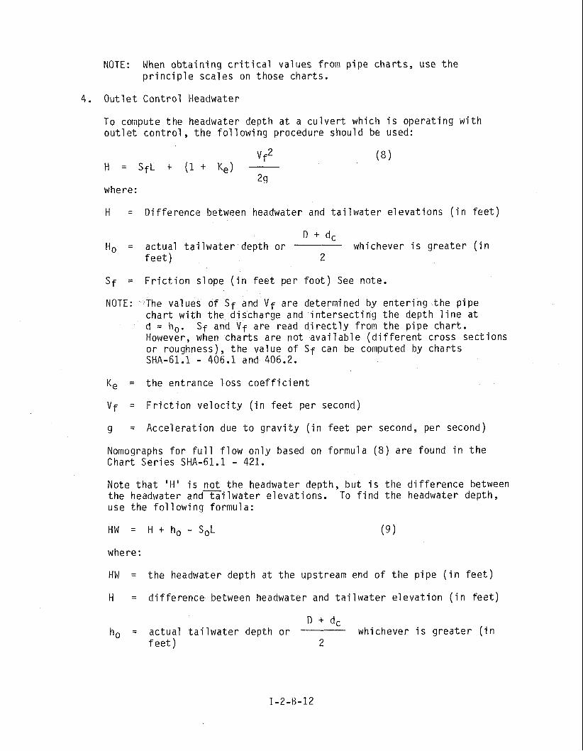
NOTE: When o b t a i n i n g c r i t i c a l va lues f rom p i p e cha r t s , use t h e p r i n c i p l e sca les on those char ts .
4. O u t l e t Con t ro l Headwater
To compute t h e headwater depth a t a c u l v e r t which i s ope ra t i ng w i t h out1 e t c o n t r o l , t h e f o l l owi ng procedure should be used:
where:
H = D i f f e rence between headwater and t a i l w a t e r e l e v a t i o n s ( i n f e e t )
D + dc H, = ac tua l t a i l w a t e r depth o r whichever i s g r e a t e r ( i n
f e e t ) 2
Sf = F r i c t i o n s lope ( i n f e e t pe r f o o t ) See note.
NOTE: The values o f Sf and V f a re determined by e n t e r i n g t h e p i p e c h a r t w i t h t h e d ischarge and i n t e r s e c t i n g t h e depth l i n e a t d = h,. S f and V f a re read d i r e c t l y f rom t h e p i p e cha r t . However, when c h a r t s a re no t a v a i l a b l e ( d i f f e r e n t cross sec t ions o r roughness), t h e va lue o f Sf can be computed by c h a r t s SHA-61.1 - 406.1 and 406.2.
K e = t h e ent rance l o s s c o e f f i c i e n t
V f = F r i c t i o n v e l o c i t y ( i n f e e t pe r second)
g = Acce le ra t i on due t o g r a v i t y ( i n f e e t per second, per second)
Nomographs f o r f u l l f l o w o n l y based on fo rmu la ( 8 ) a re found i n t h e Char t Se r i es SHA-61.1 - 421.
Note t h a t ' H I i s - n o t t h e headwater depth, b u t i s t h e d i f f e r e n c e between t h e headwater and t a i l w a t e r e l eva t i ons . To f i n d t h e headwater depth, use t h e f o l l o w i n g formula:
where:
HW = t h e headwater depth a t t h e upstream end o f t h e p i pe ( i n f e e t )
H = d i f f e r e n c e between headwater and t a i l w a t e r e l e v a t i o n ( i n f e e t )
D + dc ho = ac tua l t a i l w a t e r depth o r whichever i s g r e a t e r ( i n
f e e t ) 2

So = a c t u a l s l o p e o f t h e c u l v e r t ( i n f e e t p e r f o o t )
L = Length o f t h e c u l v e r t ( i n f e e t )
D = D iameter o f r i s e o f c u l v e r t ( i n f e e t )
dc = c r i t i c a l d e p t h ( i n f e e t ) See n o t e under i n l e t c o n t r o l
*NOTE: The v a l u e s o f Sf and V f a r e de te rm ined by e n t e r i n g t h e p i p e c h a r t w i t h t h e d i s c h a r g e and i n t e r s e c t i n g t h e dep th l i n e a t d = ho, Sf and V f a r e read d i r e c t l y f rom t h e p i p e c h a r t . However, when c h a r t s a r e n o t a v a i l a b l e ( d i f f e r e n t c r o s s s e c t i o n s o r roughness), t h e v a l u e o f Sf can be computed by c h a r t s SHA-61.1 - 406.1 and 406.2.

ENTRANCE LOSS COEFFICIENTS
Type o f S t r u c t u r e and Des ign o f E n t r a n c e Coef f i c i e n t Ke
P ipe, Concre te
P r o j e c t i n g f r o m f i 11 , s o c k e t end (groove-end)-- - - - - - - - - - - - - 0.2 P r o j e c t i n g f r o m f i l l , sq. c u t end-------------------------- 0.5 Headwal l o r headwal l and w i n g w a l l s
Socket end o f p i p e (groove-end)-- - - - - - - - - - - - - - - - - - - - - - - - 0.2 Square-edge--------------------------------------------- 0.5 Rounded ( r a d i u s = l/lzD)-------------------------------- 0.2
M i t e r e d t o conform t o fill slope--- - - - - - - - - - - - - - - - - - - - - - - - - - 0.7 *End-Sect ion con fo rm ing t o f i l l s lope--- - - - - - - - - - - - - - - - - - - - - 0.5
P i p e o r P i pe-Arch, Cor ruga ted Me ta l
P r o j e c t i n g f r o m f i l l , (no headwal l ) - - - - - - - - - - - - - - - - - - - - - - - - - 0.9 Headwall o r headwal l and w i n g a l 1s
Square-edge---------------------------------------------- 0.5 M i t e r e d t o conform t o fill slope--- - - - - - - - - - - - - - - - - - - - - - - - - - 0.7 *End-Sect ion con fo rm ing t o f i l l s lope--- - - - - - - - - - - - - - - - - - - - - 0.5
Box, R e i n f o r c e d Concre te
Headwall para1 1 e l t o embankment (no w i ngwa l l s ) Square-edged on 3 edges---------------------------------- 0.5
Rounded on 3 edges t o r a d i u s o f 1/12 b a r r e l l d imension--- - - - - - - - - - - - - - - - - - - - - - - - - - - - - - - - - - - - - - - - - - - - - - 0.2
l d ingwa l l s a t 30 t o 75 t o b a r r e l l Square-edged a t crown---- - - - - - - - - - - - - - - - - - - - - - - - - - - - - - - - - 0.4
Crown edge rounded t o r a d i u s o f 1/12 b a r r e l 1 dimension------------------------------------------------ 0.2
Wingwal ls a t 10 t o 25 t o b a r r e l l Square-edged a t crown------------------------------------ 0.5
Wingwal ls p a r a l l e l ( e x t e n s i o n o f s i d e s ) Square-edged a t crown------------------------------------ 0.7
*NOTE: "End S e c t i o n con fo rm ing t o f i l l s lope," made o f e i t h e r me ta l o r c o n c r e t e , a r e t h e s e c t i o n s commonly a v a i l a b l e f r o m manu fac tu re rs . From l i m i t e d h y d r a u l i c t e s t s t h e y a r e e q u i v a l e n t i n o p e r a t i o n t o headwal l i n b o t h i n l e t and o u t l e t c o n t r o l .
MARYLAND STATE HIGHWAY ADMINISTRATION
1-2-5-14

I VALUES OF K f FOR CORRESPONDING VALUES OF R
I
R= HYDRAULIC RADIUS = AREA OF PIPE / PERIMETER OF PIPE I
1 . 1
COMPUTATION OF FRICTION SLOPE
Sf= ( n v ~ f ' (K f ) WHERE
~=MANNING'S COEFFICIENT (SEE CHART - SHA-61.1-404 I )
V= A- K+= FRICTION SLOPE COEFFICIENT (k4,; f AREA
3 . 4 .0886 .0882 .Of379 .0875 . 0 8 7 2 3.5 . 0 8 5 2 .0849 .0846 , 0 8 4 3 .0839 3 . 6 . 0 8 2 1 .0818 .0815 .0812 .0809 3 . 7 .0791 .0788 .0786 .0783 .0780 3 .8 - 0 7 6 4 . 0 7 6 1 .0758 .0756 .0753 3 . 9 .0738 ,0735 . 0 ? 3 3 .0730 .0725 4 . 0 . a 7 1 3 . 0 7 1 1 .0708 .0706 , 9 7 0 4 4 . 1 .0690 .0685 .0686 .Oh83 . 0 6 8 1 4 . 2 .0668 .0666 . 0 6 6 4 .0662 .0660 4 . 3 .06b8 .0646 . 0 6 4 4 .06L2 .0640 4 . 4 .0628 .0526 . 0 6 2 4 .0622 . 0 6 2 1 4.5 , 0 6 1 0 .0608 .0606 .0604 .COO2 4 . 6 .0592 . 0 5 9 0 .05&9 .0587 .0585 4 . 7 .0575 . 0 5 7 4 . 0 5 7 2 .0570 .0563 4 . 8 , 0 5 5 s . 0 5 5 b .0556 .0555 .0553 4.9 .0544 . 0 5 4 3 . 0 5 4 1 .0540 .0538 5 . 0 . 0 5 3 0 .0528 .0527 .O525 .0514
--
TABLE OF FRICTIOM SLOPE COEFFICIENTS, Ki
MARYLAND STATE HIGHWAY ADM~NISTRAT!ON

I COMPUTATiON OF FRICTION SLOPE
n = MANNING'S COEFF IClENT (SEE CilART - SHA-61.1-404.1 1
v= 0 f AREA
K+= FRICTION SLOPE COEFFICIENT l&?,i
VALUES OF K f FOR CORRESPONDING VALUES OF R
R= HYDRAULIC RADIUS = AREA OF PlPE / PERIMETER OF PlPE
-- ! .o .1 . 2 .3 .4 .5 .6 . 7 . 8 .9
-
TABLE OF FRICTION SLOPE COEFFICIENTS, K f I-- / MARYLAND STATE H!GHWAY ADMINI STHATION 8/78 SHA-61.1-406.2
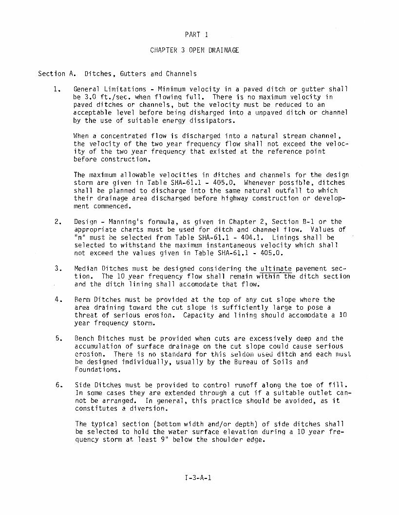
CHAPTER 3 OPEN DRAINAGE
Sec t i on A. D i t ches , Gut ters and Channels
1. General L i m i t a t i o n s - Minimum v e l o c i t y i n a paved d i t c h o r g u t t e r s h a l l be 3.0 f t . / sec . when f l o w i n g f u l l . There i s no maximum v e l o c i t y i n paved d i t ches o r channels, bu t t h e v e l o c i t y must be reduced t o an acceptab le l e v e l be fo re be ing d isharged i n t o a unpaved d i t c h o r channel by t h e use o f s u i t a b l e energy d i s s i p a t o r s .
When a concen t ra ted f l o w i s d ischarged i n t o a n a t u r a l stream channel , t h e v e l o c i t y o f t h e two y e a r f requency f l o w s h a l l no t exceed t h e ve l oc- i t y o f t h e two y e a r f requency t h a t e x i s t e d a t t h e re fe rence p o i n t be fo re cons t ruc t i on .
The maximum a l l owab le v e l o c i t i e s i n d i t c h e s and channels f o r t h e design storm a re g iven i n Tab le SHA-61.1 - 405.0. Whenever poss ib l e , d i t c h e s s h a l l be planned t o d ischarge i n t o t h e same n a t u r a l o u t f a l l t o wh ich t h e i r dra inage area d ischarged be fo re highway c o n s t r u c t i o n o r develop- ment commenced.
2. Design - Manning's formula, as g iven i n Chapter 2, Sec t ion B-1 o r t h e app rop r i a t e cha r t s must be used f o r d i t c h and channel f l ow. Values o f "nu must be se lec ted f rom Table SHA-61.1 - 404.1. L i n i n g s s h a l l be se l ec ted t o w i t hs tand t h e maximum instantaneous v e l o c i t y which s h a l l no t exceed t h e va lues g iven i n Table SHA-61.1 - 405.0.
3. Median D i tches must be designed cons ide r i ng t h e u l t i m a t e pavement sec- t i o n . The 10 yea r f requency f l o w s h a l l remain w i t h i n t h e d i t c h s e c t i o n and t h e d i t c h l i n i n g s h a l l accornodate t h a t f low.
4. Berm D i tches must be p rov i ded a t t h e t o p o f any c u t s lope where t h e area d r a i n i n g toward t h e c u t s lope i s s u f f i c i e n t l y l a r g e t o pose a t h r e a t o f se r ious eros ion. Capac i ty and l i n i n g should accomodate a 10 yea r frequency storm.
5. Bench D i tches must be p rov i ded when cu t s a re excess i ve l y deep and t h e accumulat ion o f su r f ace dra inage on t h e c u t s lope c o u l d cause s e r i o u s ercsjsn. Thzre 4s no standard for t h i s seldom used d i t c h and each muse be designed i n d i v i d u a l l y , u s u a l l y by t h e Bureau o f S o i l s and Foundat ions.
6. S ide D i tches must be p rov i ded t o c o n t r o l r u n o f f a long t h e t o e o f f i l l . I n some cases t hey a re extended th rough a c u t i f a s u i t a b l e o u t l e t can- no t be arranged. I n general , t h i s p r a c t i c e should be avoided, as i t c o n s t i t u t e s a d i ve r s i on .
The t y p i c a l s e c t i o n (bo t tom w i d t h and/or depth) o f s i d e d i t c h e s s h a l l be se l ec ted t o ho ld t h e water su r f ace e l e v a t i o n d u r i n g a 10 y e a r f r e - quency s torm a t l e a s t 9 " below t he shoulder edge.

7. S u r f a c e D r a i n d i t c h e s a r e n o r m a l l y V-shaped d i t c h e s used t o c o l l e c t r u n o f f f rom t h e roadway and s l o p e s t h r o u g h c u t areas. However, when d ra inage f rom s i d e d i t c h e s i s c a r r i e d t h r o u g h a c u t , a f l a t bo t tom d i t c h must be used. I n e i t h e r case, t h e w a t e r s u r f a c e e l e v a t i o n d u r i n g a 10 y e a r f requency s t o r m s h a l l remain a t l e a s t 9" below t h e s h o u l d e r edge.
8. O u t l e t D i t c h e s , I n l e t D i t c h e s , and Other Channel Improvements. Any d i t c h wh ich serves as an o u t l e t o r i n l e t f o r an open c u l v e r t , rega rd - l e s s o f i t s p r i m a r y f u n c t i o n , w i l l be des igned t o accomodate t h e same r u n o f f t h a t t h e c u l v e r t i t serves i s des igned f o r .
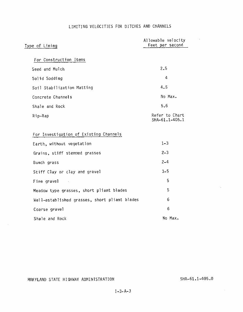
LIMITING VELOCITIES FOR DITCHES AND CHANNELS
Type o f L i n i n g
F o r C o n s t r u c t i o n I tems
Seed and Mulch
So l i d Soddi ng
S o i l S t a b i l i z a t i o n M a t t i n g
Conc re te Channels
Sha le and Rock
R i p-Rap
F o r I n v e s t i g a t i o n o f E x i s t i n g Channels
E a r t h , w i t h o u t v e g e t a t i o n
Gra ins , s t i f f stemmed grasses
Bunch g rass
S t i f f C l a y o r c l a y and g r a v e l
F i n e g r a v e l
Meadow t y p e grasses, s h o r t p l i a n t b lades
W e l l - e s t a b l i s h e d grasses, s h o r t p l i a n t b lades
Coarse g r a v e l
Sha le and Rock
MARYLAND STATE HIGHWAY ADMINISTRATION
I-3-A-3
A1 1 owabl e ve l o c i t y Fee t p e r second
No Max.
5.6
R e f e r t o C h a r t SHA-61.1-405.1
1-3
2-3
2-4
3-5
5
5
6
6
No Max.
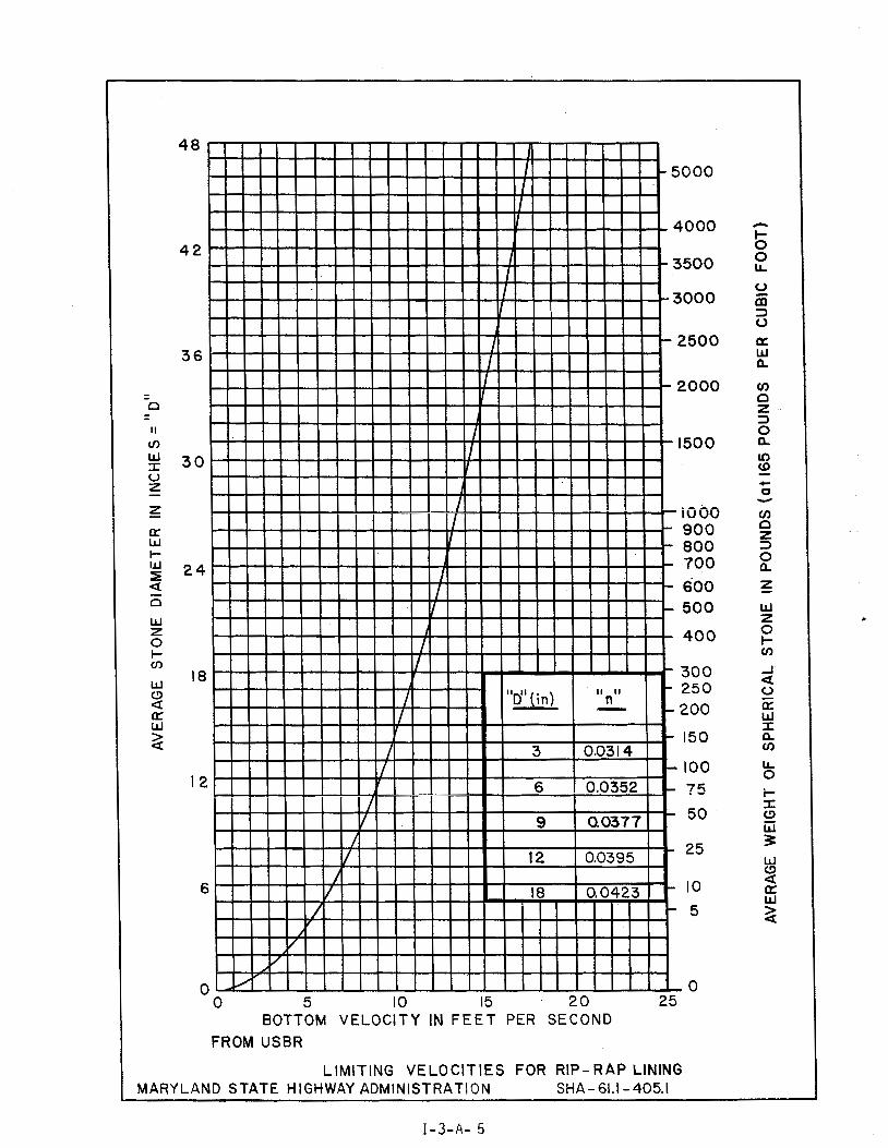
0 5 10 15 20 2 5 BOTTOM VELOCITY IN F E E T PER SECOND
FROM USBR
LIMITING VELOCIT IES FOR RIP- R A P LINING 'LAND STATE HIGHWAY ADMINISTRATION SHA - 61.1 - 405.1
Sec t i on 5. INLETS
1. General L i m i t a t i o n s - I t i s not necessary t o determine t h e capac i t y o f i n l e t s which i n t e r c e p t d i t c h f lows. The assumption i s made t h a t i f t h e p roper s i z e p i pe i s p rov i ded t o d r a i n t h e i n l e t , t h e i n l e t w i l l i n t e r - cept a l l o f t h e water reach ing it.
2. Median I n l e t s w i l l be spaced f o r t h e r u n o f f from t h e 10 y e a r f requency storm, based on t h e c a p a c i t y o f t h e d i t c h sec t i on , b u t they s h a l l no t be more than 1,000 f e e t apa r t . I n l e t s which cou ld be reached by v e h i c l e s must have t r a f f i c bea r i ng g ra tes .
Standard Curb Openings - Curbed pavement sec t ions a re commonly used i n in terchanges and o the r areas w i t h su r f ace d r a i n o r s i d e d i t c h e s con- s t r u c t e d beyond t h e curb. I n these cases, f l o w f rom t h e cu rb and g u t t e r s e c t i o n can be d ischarged t o t h e d i t c h th rough Standard Curb Openings. Curb openings should be spaced as o u t l i n e d i n Chapter 4, Sec t i on A-1. For des ign purposes curb openings s h a l l be t r e a t e d as undepressed curb opening i n l e t s . Chart s e r i e s SHA-61 . l -431 s h a l l be used t o determine capac i t y .
I n areas where t h e d i f f e r e n c e i s e l e v a t i o n between t h e g u t t e r f l o w l i n e and t h e d i t c h f l o w 1 i n e i s g rea te r than 5 f e e t , t h e use o f cu rb openings i s no t recommended and t h e des igner should use s tandard cu rb and g u t t e r i n l e t s d i scha rg i ng t o t h e d i t c h v i a pipe. These i n l e t s s h a l l a l s o be spaced as s p e c i f i e d f o r i n Chapter 4, Sec t i on A-1. Standard curb openings should not be used i n areas where f u t u r e s idewalk o r storm d r a i n c o n s t r u c t i o n may be expected.

S e c t i o n C. PIPE CULVERTS
General L i m i t a t i o n s
Me ta l 1 i c coa ted c o r r u g a t e d me ta l p i p e s (ASSHTO D e s i g n a t i o n M36-81 I ) under a s t a t e h ighways s h a l l be a minimum o f 14 gauge and 16 gauge under ent rances. Minimum gauge based on h e i g h t o f cove r must be d e t e r - mined i n accordance w i t h AASHTO S p e c i f i c a t i o n s S e c t i o n 1.9.2. H e i g h t o f f i l l l i m i t s f o r commonly used s t e e l gauges and p i p e s i z e s a r e g i ven i n Tab les SHA-61.1 - 407.0 t h r u 407.2. H e i g h t o f f i l l l i m i t s f o r t o p and s i d e p l a t e s o f s t r u c t u r a l p l a t e p i p e s a r e g i v e n i n T a b l e SHA 61.1- 407.3. The bo t tom p l a t e s w i l l be o f t h e n e x t h e a v i e r gauge. Cor ruga ted Aluminum A1 l o y p i p e s (AASHTO D e s i g n a t i o n M 196-801) may be used o n l y w i t h pe rm iss ion o f t h e Ch ie f -Bureau o f Highway Design. The p rocedure f o r comput ing t h e r e q u i r e d gauge o f any c o r r u g a t e d meta l p i p e i s e x p l a i n e d i n Appendix 4.
The s tandard d e s i g n i t e m f o r S t a t e p r o j e c t s i s c o r r u g a t e d s t e e l p i p e w i t h 2 2 /3" X 1 /2 " h e l i c a l c o r r u g a t i o n . P i p e w i t h 3" X 1" and /o r a n n u l a r c o r r u g a t i o n s s h o u l d o n l y be c o n s i d e r e d under e x t r e m e l y h i g h f i l l s .
A l l c o r r u g a t e d me ta l p i p e s w i l l n o t be b i t u m i n o u s coated u n l e s s t e s t s s f t h e wa te r i n d i c a t e a d e f i n i t e need f o r it. A i l c o n c r e t e p i p e s s h a i i be a minimum o f C l a s s I V s t r e n g t h when used w i t h i n t h e SHA r i g h t - o f - way. Maximum h e i g h t o f f i l l a1 lowed over c o n c r e t e p i p e i s de te rm ined f r o m Tab le SHA-61.1 - 407.4 and i s measured f r o m t h e t o p o f t h e p i p e t o t h e crown o f t h e pavement. Minimum cover f o r a l l p ipes s h a l l be 0.75 f e e t measured f r o m t h e t o p o f t h e p i p e t o t h e bo t tom o f t h e r o a d me ta l o r a t l e a s t a t o t a l o f one f o o t i n n o n - t r a f f i c areas. V i t r i f i e d c l a y l i n e r s s h a l l be used o n l y when t e s t s o f t h e w a t e r i n d i c a t e a d e f i n i t e need f o r it. E l 1 i p t i c a l c o n c r e t e p i p e l a r g e r t h a n 53" X 34 " s h a l l n o t be used i n t h e S t a t e Highway A d m i n i s t r a t i o n R i g h t o f Way where s u b j e c t t o H-20 l o a d i n g . M u l t i p l e l i n e s o f p i p e o r p i p e arches s h a l l be spaced so t h a t a d j a c e n t o u t s i d e s u r f a c e s a r e as f o l l o w s :
D iameter o r span l e s s t h a n 48" - n o t l e s s t h a n two f e e t a p a r t .
D iamete r o r span g r e a t e r t h a n 48" - one h a l f d i a m e t e r o r t h r e e f e e t a p a r t , whichever i s less.
Pipe end s e c t i o n s s h o u l d n o t be s u b s t i t u t e d f o r endwa l l s i f :
1) Skew o f p i p e i s g r e a t e r t h a n 60 degrees t o t h e normal . 2 ) The p i p e c a r r i e s a c o n s t a n t f l ow .
T ransve rse p i p e s may n o t be s m a l l e r t h a n 18 i n c h e s i n d iamete r . Where t h e l e n g t h o f p i p e exceeds 60 f e e t , t h e minimum i s 24 i n c h e s i n d iameter .
Cor ruga ted me ta l p i p e a r c h c u l v e r t s o r r e i n f o r c e d c o n c r e t e e l 1 i p t i c a l c u l v e r t s may be used o n l y when l a c k o f a v a i l a b l e c o v e r makes use o f round p i p e s i m p r a c t i c a l o r when t h e i r use i s d i c t a t e d by h y d r a u l i c c o n s i d e r a t i o n s .

HEIGHT OF COVER LIMITS*
Th ickness
S i z e
12" 15 18 2 1 24 27 L 30 0 s 36 42 * 48 5 54 'F 'F
na 60 ,c 66 .ft 72 7 8 8 4 90 9 6
Th ickness
S i z e
f o r He1 i c a l l y Cor ruga ted S t e e l P i p e 2 213" x 112" C o r r u a a t i o n s
18. Ga. .052"
16 Ga. 14 Ga. 12 Ga. .064" .079" . l o g "
3 " x 1" C o r r u g a t i o n s
16 Ga. 14 Ga. 12 Ga. 10 Ga. 8 Ga. .064" .079" . l og " .138" .168"
* Values computed a c c o r d i n g t o AASHTO S p e c i f i c a t i o n s f o r B r i d g e s S e c t i o n 1.9.2 C u r r e n t E d i t i o n and I n t e r i m
** and *** See no tes on t a b l e SHA 61.1-407.2
MARY LAND STATE H I GHWAY ADMINISTRATION
I-3-C-2
SHA 61.1-407.0

HEIGHT OF F I L L LIMITS* f o r Annu la r Cor ruga ted S t e e l P i p e
R i v e t e d - 2 2/3" X 112" C o r r u g a t i o n
Th ickness 16 Ga. 14 Ga. 12 Ga. 10 Ga. 8 Ga. .064" .079" 1 0 9 " .138" .168"
S i z e
** ** ** ** S i n g l e R i v e t ** 6 3 56 4 7 49 46 45 Double R i v e t 4 3 4 3 4 2 42 42
*** ***
R i v e t e d - 3" X 1" C o r r u g a t i o n
Th ickness 16 Ga. 14 Ga. 12 Ga. 10 Ga. 8 Ga. .064" .079" . log" .138" .168"
S i z e
36" 5 3 66 7 7 89 100 4 2 4 5 56 64 7 1 78 48 39 49 56 6 1 6 6 54 35 4 4 51 5 5 58 6 0 3 1 3 9 49 5 1 53 66 29 36 47 48 50 72 26 33 4 5 47 48 78 &
s 2 4 3 0 44 4 5 46
8 4 L rb aJ n
2 2 28 4 2 44 4 5 90 S L q 2 1 2 6 39 4 4 44 96 'i2 a, ***
rb n 2 4 36 43 44 *** 102 .v .r 2 3 3 4 4 1 43
108 *** **J, 32 39 4 3 a,= 114 n v *** *** 3 1 37 4 1
120 Z & - - 29 3 5 3 9 126 - - *** 33 3 7 132 - - - 3 2 3 5 138 - - - 30 34 144 - - - *** 32
*Val ues computed a c c o r d i n g t o AASHTO S p e c i f i c a t i o n s f o r B r i d g e s S e c t i o n 1.9.2 C u r r e n t E d i t i o n and I n t e r i m
** and *** See no tes on t a b l e SHA 61.1-407.2
MARYLAND STATE HIGHWAY ADMINISTRATION
I-3-C-3
SHA 61.1-407.1
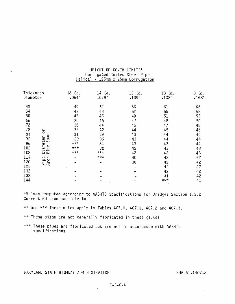
Thickness Diameter
HEIGHT OF COVER LIMITS* Cor ruga ted Coated S t e e l P ipe
H e l i c a l - 125mm x 25mm C o r r u g a t i o n
16 Ga. 14 Ga. 12 Ga. .064" .079" . l o g u
10 Ga. .138"
8 Ga. .168"
*Values computed a c c o r d i n g t o AASHTO S p e c i f i c a t i o n s f o r B r i d g e s S e c t i o n 1.9.2 C u r r e n t E d i t i o n and I n t e r i m
** and *** These no tes app ly t o Tab les 407,n3 407,1, 407=2 and 407,3.
** These s i z e s a r e n o t g e n e r a l l y f a b r i c a t e d i n t h e s e gauges
*** These p i p e s a r e f a b r i c a t e d b u t a r e n o t i n accordance w i t h AASHTO s p e c i f i c a t i o n s
MARYLAND STATE HIGHWAY ADMINISTRATION
I-3-C-4
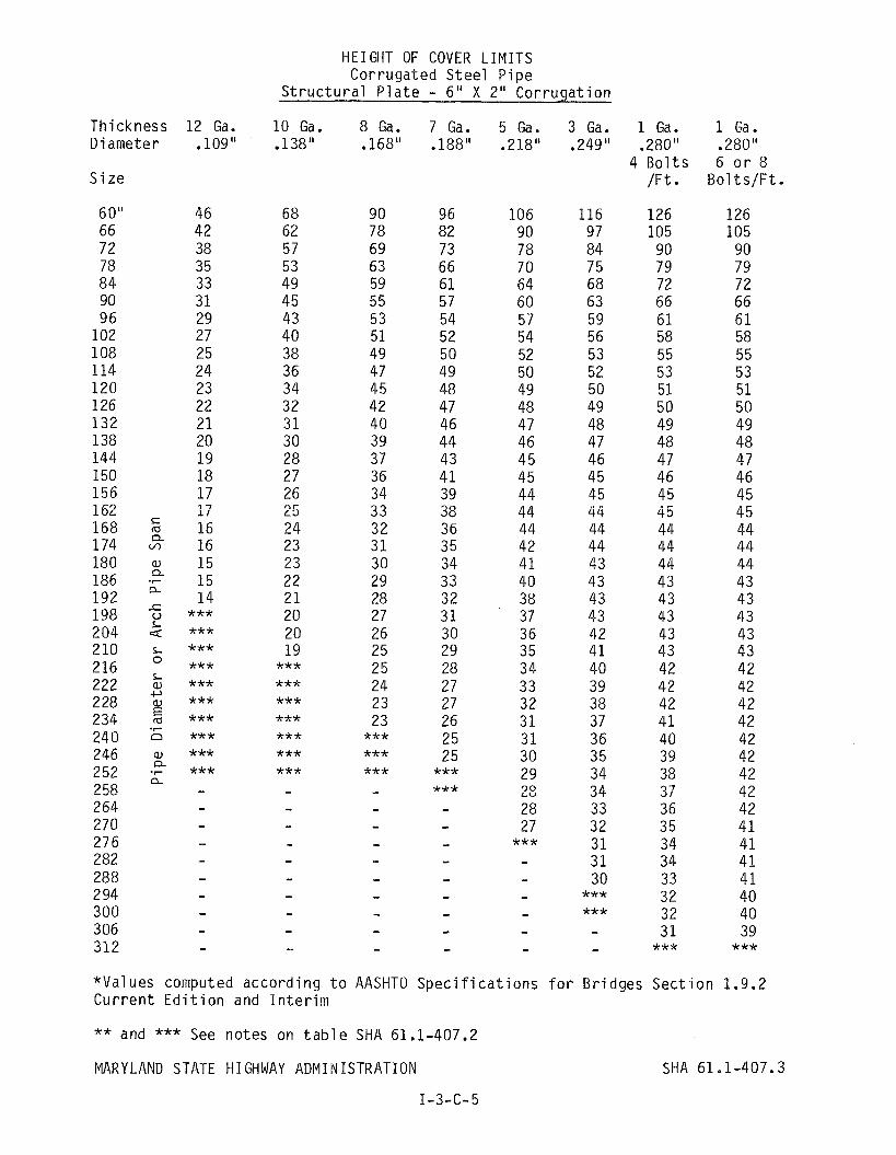
HEIGHT OF COVER LIMITS Cor ruga ted S t e e l P i p e
S t r u c t u r a l P l a t e - 6 " X 2" C o r r u g a t i o n
Th ickness 12 Ga. 10 Ga. 8 G a . 7 G a . 5 G a . 3 Ga. 1 Ga. 1 Ga. D iamete r .109" .138" .168" .188" .218" .249" .280" .280H
4 B o l t s 6 o r 8 S i z e / F t . B o l t s / F t .
*Values computed a c c o r d i n g t o AASHTO S p e c i f i c a t i o n s f o r B r i d g e s S e c t i o n 1.9.2 C u r r e n t E d i t i o n and I n t e r i m
** and *** See no tes on t a b l e SHA 61.1-407.2
MARY LAND STATE HIGHWAY ADMINISTRATION
I -3-C- 5
SHA 61.1-407.3
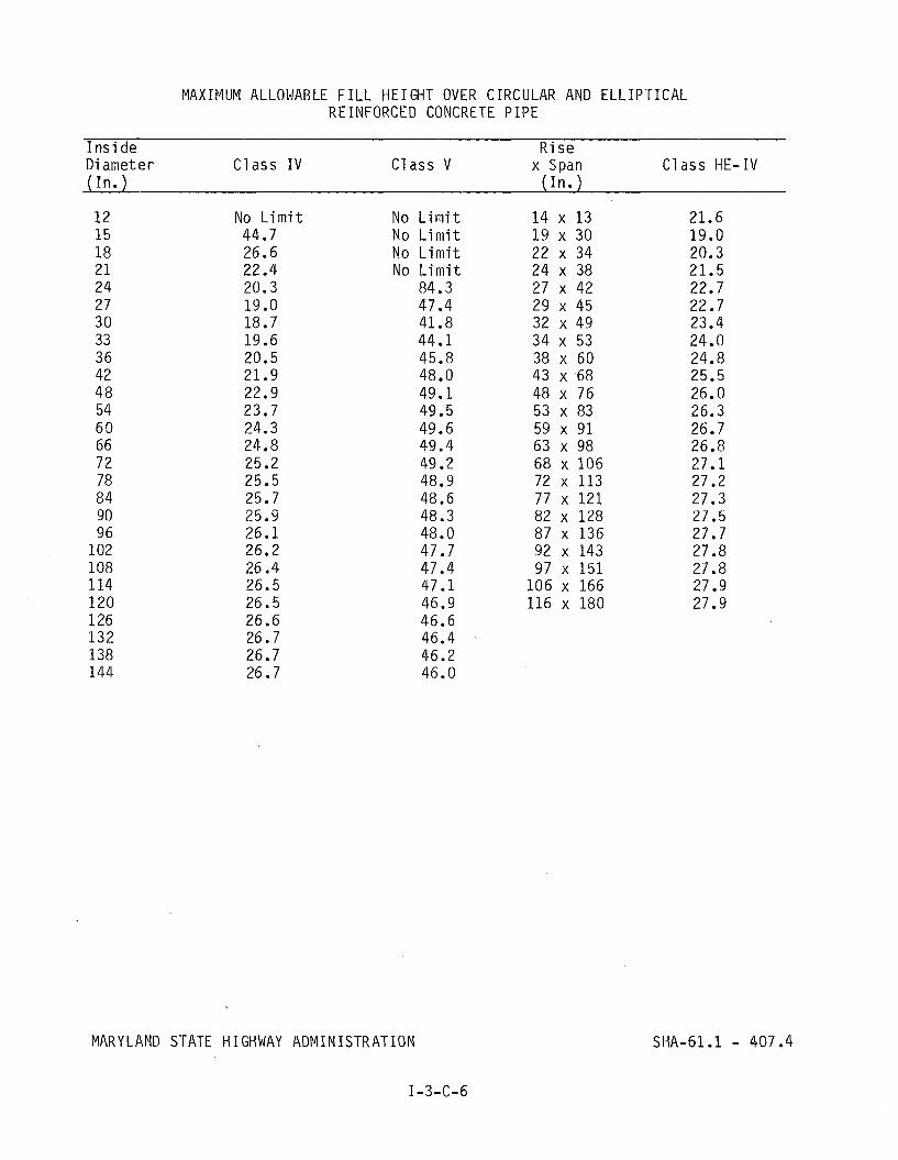
MAXIMUM ALLOWABLE F ILL HEIGHT OVER CIRCULAR AND ELLIPTICAL REINFORCED CONCRETE PIPE
I n s i d e R i s e Diameter C lass I V C lass V x Span C lass HE-IV ( I n . ) ( I n *
12 No L i m i t No L i m i t 14 x 13 21.6 15 44.7 No L i m i t 19 x 30 19.0 18 26.6 No L i m i t 22 x 34 20.3 2 1 22.4 No L i m i t 24 x 38 21.5 24 20.3 84.3 27 x 42 22.7 2 7 19.0 47.4 29 x 45 22.7 3 0 18.7 41.8 32 x 49 23.4 33 19.6 44.1 34 x 53 24.0 3 6 20.5 45.8 38 x 60 24.8 42 21.9 48.0 43 x 68 25.5 48 22.9 49.1 48 x 76 26.0 54 23.7 49.5 53 x 83 26.3 6 0 24.3 49.6 59 x 91 26.7 6 6 24.8 49.4 63 x 98 26.8 72 25.2 49.2 68 x 106 27.1 78 25.5 48.9 72 x 113 27.2 84 25.7 48.6 77 x 121 27.3 90 25.9 48.3 82 x 128 27.5 96 26.1 48.0 87 x 136 27.7
102 26.2 47.7 92 x 143 27.8 108 26.4 47.4 97 x 151 27.8 114 26.5 47.1 106 x 166 27.9 120 26.5 46.9 116 x 180 27.9 126 26.6 46.6 132 26.7 46.4 138 26.7 46.2 144 26.7 46.0
MARYLAND STATE HIGHWAY ADMINISTRATION
I-3-C-6

2. P i p e C u l v e r t s f o r Highways on New L o c a t i o n s - S t r u c t u r e s f o r h ighways on new l o c a t i o n s must be des igned t o accomodate t h e r u n o f f based on e x i s t i n g c o n d i t i o n s from, a t l e a s t , t h e des ign f l o o d .
I n Appendix B o f t h e Mary land S t a t e Highway Needs I n v e n t o r y , F u n c t i o n a l C l a s s i f i c a t i o n i s de f i ned . The Des ign F l o o d Frequency f o r t h e s e c l a s - s i f i c a t i o n s i s as f o l l o w s :
AASHTO Highway Needs I n v e n t o r y Minimum O v e r t o p p i ng C l a s s i f i c a t i o n C l a s s i f i c a t i o n Des ign F l o o d Frequency
Expressways I P r i n c i p a l A r t e r i a1 s 100
A r t e r i a1
Col l e c t o r s
I 1 I n t e r m e d i a t e A r t e r i a l s I 1 1 M i n o r A r t e r i a l s
I V M a j o r C o l l e c t o r s V M i n o r C o l l e c t o r s
Loca l Roads & S t r e e t s V I Loca l S t r e e t s 10
F o r d e s i g n purposes, t h e p r o j e c t e d F u n c t i o n a l C l a s s i f i c a t i o n as g i v e n i n t h e Mary land S t a t e Highway Needs I n v e n t o r y s h a l l be used. F o r roads n o t i n c l u d e d i n t h e Mary land S t a t e Highway Needs I n v e n t o r y , t h e c o r r e c t c l a s s i f i c a t i o n can be o b t a i n e d f r o m S.H.A.'s Bureau o f Highway S t a t i s t i c s .
F o r each highway c a t e g o r y and des ign f l o o d , t h e headwater poo l w i t h i n our r i g h t - o f - w a y w i l l be a l l o w e d t o reach t h e edge o f pavement.
As no g r a d i n g w i l l be p e r m i t t e d i n t h e two-year channe l , t h a t p o r t i o n o f t h e s t r u c t u r e t o be l o c a t e d i n t h e channel must have t h e c a p a c i t y t o hand le t h e two-year r u n o f f . The remainder o f t h e s t r u c t u r e s , i f any, may he p l a c e d i n t h e f l o o d p l a i n . I f necessary, t h e f l o o d p l a i n may be regarded t o accomodate t h e s e a d d i t i o n a l c u l v e r t s .
I n no even t , rega rd1 ess o f t h e Des ign F lood , may t h e new 100 y e a r f l o o d p l a i n be i n c r e a s e d above t h e e l e v a t i o n wh ich e x i s t e d p r i o r t o c o n s t r u c - t i o n . I f t h e v e r t i c a l a1 ignment i s such t h a t t h e l o w e s t pavement edge i s above t h e e x i s t i n g 100 y e a r f l o o d p l a i n , t h e c u l v e r t must be des igned t o pass t h e 100 year f l g ~ d . Any i n c r e a s e i n t h e 100 y e a r f l o o d p l a i n due t o i n c r e a s e d r u n o f f must be c o n t a i n e d w i t h i n t h e r i g h t o f way o r easement.
3. P i p e C u l v e r t s f o r R e h a b i l i t a t e d o r D u a l i z e d Highways - Old o r c o l l a p s e d c u l v e r t s s h o u l d be r e p l a c e d w i t h c u l v e r t s w i t h t h e same c a p a c i t y . I f t h e d e s i g n f l o o d f o r t h a t c l a s s o f highway f l o o d e d t h e road, t h e c u l - v e r t s i z e may be i n c r e a s e d t o accommodate t h e des ign f l o o d and l o w e r t h e headwater t o t h e edge o f pavement.
4. Des ign - When t h e headwater poo l a t t h e e n t r a n c e t o a c u l v e r t o f any g i v e n s i z e can be c o n f i n e d , i t may be s a i d t h a t t h e depth o f t h e head- w a t e r poo l w i l l i n c r e a s e u n t i l s u f f i c i e n t head has been b u i l t t o pass t h e f l o w a t t h e r a t e t h a t i t a r r i v e s a t t h e c u l v e r t . T h i s head may be r e q u i r e d t o :
1 ) p r o v i d e t h e energy necessary t o ge t t h e r e q u i r e d f l o w i n t o t h e c u l v e r t , o r
2 ) p r o v i d e t h e energy necessary t o move t h e r e q u i r e d f l o w t h r o u g h t h e c u l v e r t and d i s c h a r g e it. The head w i l l b u i l d up t o s a t i s f y e i t h e r 1 o r 2, wh ichever i s g r e a t e r .
When t h e g r e a t e r head i s r e q u i r e d t o d i r e c t a g i v e n f l o w i n t o t h e c u l v e r t , t h e c u l v e r t i s s a i d t o be o p e r a t i n g under i n l e t c o n t r o l . T y p i c a l l y , t h e Manning c h a r t w i l l i n d i c a t e t h a t t h e c u l v e r t i s f l o w i n g o n l y p a r t i a l l y f u l l . P r a c t i c a l measures wh ich can be t a k e n t o reduce t h e r e q u i r e d head when t h e r a t e o f f l o w and p i p e s i z e a r e f i x e d a re :
1 ) Add a headwal l t o p r o t r u d i n g p i p e s 2 ) Round t h e edge o f t h e headwal l open ing
When t h e g r e a t e r head i s r e q u i r e d t o move a g i v e n f l o w t h r o u g h t h e c u l v e r t and d i s c h a r g e it, t h e c u l v e r t i s s a i d t o be o p e r a t i n g w i t h o u t l e t c o n t r o l . T y p i c a l ly , t h e Manning 's p i p e c h a r t w i l l i n d i c a t e t h a t t h e c u l v e r t i s f l o w i n g under p r e s s u r e when t h i s t y p e o f o p e r a t i o n i s encountered and/or t h e c u l v e r t w i l l be found t o be d i s c h a r g i n g a g a i n s t c o n s i d e r a b l e t a i l w a t e r . P r a c t i c a l measures wh ich can be t a k e n t o reduce t h e r e q u i r e d head when t h e r a t e o f f l o w and p i p e s i z e a re :
1) I n c r e a s e t h e slope s f t h e p i p e 2 ) Decrease t h e roughness c o e f f i c i e n t
When t h e s e measures a r e i n s u f f i c i e n t , i t may be necessary t o i n c r e a s e p i p e s i z e .
Form SHA-61.1-490 s h a l l be comple ted f o r t h e h y d r a u l i c d e s i g n o f a l l open c u l v e r t s .
The HW/D r e l a t i o n s h i p r e q u i r e d t o comple te t h e "En t rance C o n t r o l : p o r t i o n o f t h i s fo rm s h o u l d be o b t a i n e d f rom nomographs wh ich have been p repared f rom exper imen ta l da ta . When a nomograph i s n o t a v a i l a b l e f o r t h e t y p e and s i z e o f p i p e i n v o l v e d o f when t h e s o l u t i o n i s beyond t h e l i m i t s o f t h e nomograph, an ap rox ima te v a l u e o f HW can be e s t i m a t e d by u s i n g t h e e n t r a n c e c o n t r o l f o r m u l a #7 g i v e n i n Chapter 2, S e c t i o n B-3.
The d e t e r m i n a t i o n o f Head f g r use i n c ~ m p l e t i n g t h e o u t l e t c o n t r o l p o r t i o n o f t h e f o r m can be made f r o m a nomograph o r d i r e c t l y f r o m t h e f o r m u l a wh ich t h e nomograph was de r i ved . See f o r m u l a s #8 and #9 g i v e n i n Chap te r 2, s e c t i o n B-4. I N ALL CASES, BOTH THE INLET CONTROL AND OUTLET CONTROL PORTIONS OF THE FORM MUST BE COMPLETED.
When t e r r a i n i s f l a t and p i p e s occu r i n s e r i e s w i t h r e l a t i v e l y s h o r t i n t e r v e n i n g d i t c h e s , (as i n i n t e r c h a n g e a reas ) t h e d e s i g n e r must check back t o be s u r e t h a t t h e headwater poo l f rom any g i v e n p i p e has n o t caused a t a i l w a t e r f o r t h e p r e v i o u s p i p e and t h e r e b y s h i f t e d c o n t r o l f rom e n t r a n c e c o n t r o l t o o u t l e t c o n t r o l . When a p i p e has an i n l e t s t r u c t u r e on i t s upper end, compute t h e headwater , by t r e a t i n g i t as headwal l .

D. Box C u l v e r t s
Fo r box c u l v e r t des ign and a n a l y s i s , t h e c h a r t s p r o v i d e d i n Appendix 3 f o r v e r t i c a l s i d e d channe ls may be used. Do n o t a l l o w t h e depth o f f l o w t o exceed t h e h e i g h t o f t h e box. F o r f l o w s a t o r above " f u l l f l o w " , compen- s a t i o n f o r a d d i t i o n a l f r i c t i o n a g a i n s t t h e r o o f of t h e box c u l v e r t i s p r o v i d e d by a d j u s t i n g t h e d i scha rge . T h i s ad jus tmen t i s made by t h e equa t ion :
2 8 + 2D 213 = Q x (ad jus tmen t f a c t o r * ) (10)
*See t a b l e below f o r ad jus tmen t f a c t o r s .
where:
Q ' = t h e a d j u s t e d d i s c h a r g e ( i n c u b i c f e e t p e r second) Q = t h e a c t u a l d i s c h a r g e ( i n c u b i c f e e t p e r second) B = t h e w i d t h o f t h e box c u l v e r t ( i n f e e t ) D = t h e h e i g h t o f t h e box c u l v e r t ( i n f e e t )
Headwater compu ta t i ons f o r box c u l v e r t s a r e made s i m i l a r t o p i p e headwater computa t ions . (See Chapter 3, S e c t i o n C-4).
D I B F a c t o r

PART I
CHAPTER 4 STORM DRAIN SYSTEMS
S e c t i o n A. S t r u c t u r e s
1. I n l e t s
a. General L i m i t a t i o n s
I n a d d i t i o n t o t h o s e r e q u i r e d i n sumps, i n l e t s must a r b i t r a r i l y be l o c a t e d upgrade o f a1 1 pub1 i c road connec t ions and b r i d g e s . I n l e t s must be p r o v i d e d i n supere l e v a t i o n t r a n s i s t i o n s a p p r o x i m a t e l y 50 f e e t up grade of t h e s e c t i o n where t h e c r o s s s l o p e i s 0.00 ( l e v e l s e c t i o n )
Curb and g u t t e r i n l e t s w i l l be spaced w i t h t h e r u n o f f f rom t h e t w o y e a r storm. R e t i c u l a r g r a t e i n l e t s o r SHA s t a n d a r d c u r b open ing i n l e t s w i l l be used i n a l l cases, except on i n t e r s t a t e roadways o r w i t h p e r m i s s i o n o f t h e C h i e f , Bureau o f Highway Design. Form SHA-61.1 - 490 must be comple ted f o r a l l i n 1 e t s spacing, i n c l u d i n g sump i n l e t s .
b. I n l e t s on Grade
I n l e t s on grade s h a l l be spaced t o p i c k - u p a t l e a s t 85% o f t h e t o t a l g u t t e r f l o w and t h e maximum a l l o w a b l e spread o f f l o w i n t h e c u r b and g u t t e r s e c t i o n s h a l l be 8 f e e t . The amount o f g u t t e r f l o w i n t e r - cep ted by an i n d i v i d u a l i n l e t and t h e spread i n t h e g u t t e r s e c t i o n s h a l l be o b t a i n e d f rom t h e a p p r o p r i a t e c h a r t s . The g u t t e r f l o w approach ing any i n l e t must be a d j u s t e d t o r e f l e c t t h e bypass f r o m t h e p r e v i o u s i n 1 e t .
Where t h e s t a n d a r d c o n c r e t e b a r r i e r i s used, i t s h a l l be t r e a t e d as a c u r b and i n l e t s s h a l l be spaced on a 2 y e a r s t o r m as d e t a i l e d above. The spread o f w a t e r s h a l l n o t be a l l o w e d t o encroach on t h e t r a v e l - way.
Where r e l a t i v e l y f l a t grades wou ld r e s u l t i n r e t i c u l a r t y p e g r a t e i n l e t s b e i n g spaced c l o s e r t h a n 100 f e e t i n o r d e r t o o b t a i n 85% _ . - A - - - - - A 2 I r lLerLepc lun , t h e d e s i g n s n a i l be m o d i f i e d t o o b t a i n 80% i n t e r c e p t - t i o n t h r o u g h t h e s e areas. I n t h e s e cases, t h e a l l o w a b l e sp read w i l l remain e i g h t f e e t .
The d e s i g n and e v a l u a t i o n o f SHA s t a n d a r d c u r b open ing i n l e t s w i l l be made u s i n g a v a l u e f o r t h e l o c a l dep ress ion o f 1.5 inches. T h i s v a l u e i s s u b j e c t t o change.
The per formance o f e x i s t i n g c u r b open ing i n l e t s and para1 1 e l b a r g r a t e s may be e v a l u a t e d u s i n g t h e a p p r o p r i a t e c h a r t s .
c. Sump I n l e t s
Sump i n l e t s must be designed on a two yea r f requency storm w i t h 100% p ickup and a l i m i t i n g spread o f e i g h t f ee t . I f more than one i n l e t i s r equ i r ed t o s t ay w i t h i n p resc r i bed l i m i t s , t h e a d d i t i o n a l i n l e t ( s ) must be p laced a t p o i n t ( s ) where t h e g u t t e r grade i s 0.2 f e e t above t h e low p o i n t . The des igner should use cha r t s f o r t h e s p e c i f i c t ype o f i n l e t when ava i l ab l e . When cha r t s a re no t a v a i l a b l e an i n l e t g r a t e may be eva lua ted us i ng t h e f o l l o w i n g formula:
where:
Q = Capac i ty ( i n cub i c f e e t per second)
P = per imete r o f g r a t e opening ( i g n o r i n g bars ) ( i n f e e t )
h = head over g r a t e ( i n f e e t )
Th i s fo rmu la i s s t r i c t l y a p p l i c a b l e o n l y where h i s l e s s than 0.4 fee t . When t h i s i s g r e a t e r than 0.4 f e e t , see Appendix 2, Reference #6. I n o rde r t o compensate f o r c l ogg ing , g r a t e i n l e t s ( w i t h no curb opening) w i l l be designed w i t h t h e assumption t h a t o n l y 75% of t h e t o t a l g r a t e per imete r i s usable. I f t h e g ra te i s ad jacen t t o t h e curb, t h e per imete r w i l l f i r s t be reduced by t h e l e n g t h o f t h e s i de a t t h e curb and w i l l t hen be m u l t i p l i e d by 75% t o get t h e l e n g t h o f pe r imete r f o r design.
Combinat ion i n l e t s i n sump areas w i l l be designed w i t h t h e f u l l usab le pe r ime te r and t h e curb opening w i l l be cons idered as a f a c t o r o f s a f e t y aga ins t c logg ing.
2. Manholes must be p rov ided when t h e l e n g t h o f p i p e exceeds 400 f e e t and a t a l l j u n c t i o n s and bends, where i n t h e d e s i g n e r ' s judgement, a means o f phys i ca l access may be necessary f o r maintenance purposes.
3. Bend S t ruc tu res s h a l l be p rov ided on a l l s torm d r a i n s which a re 30 inches i n d iameter and l a r g e r , and when t h e l e n g t h o f bend, as computed by equa t ion ( 12 ) , i s g r e a t e r than 5.0 f e e t . The rad ius o f bend should be a minimum of 2 i j 2 t imes t h e p i p e d iameter . Bend s t r u c t u r e s may be designed u s i n g formulas (12) and (13) .
T = R Tan 1 / 2 A (12)
where:
L = t h e l e n g t h o f bend ( i n f e e t )
4 = t h e d e f l e c t i o n angle ( i n degrees)
R = t h e r ad ius o f t h e c e n t e r l i n e o f t h e bend ( i n f e e t )
T = t h e tangent l e n g t h ( i n f e e t )
I -4-A-2
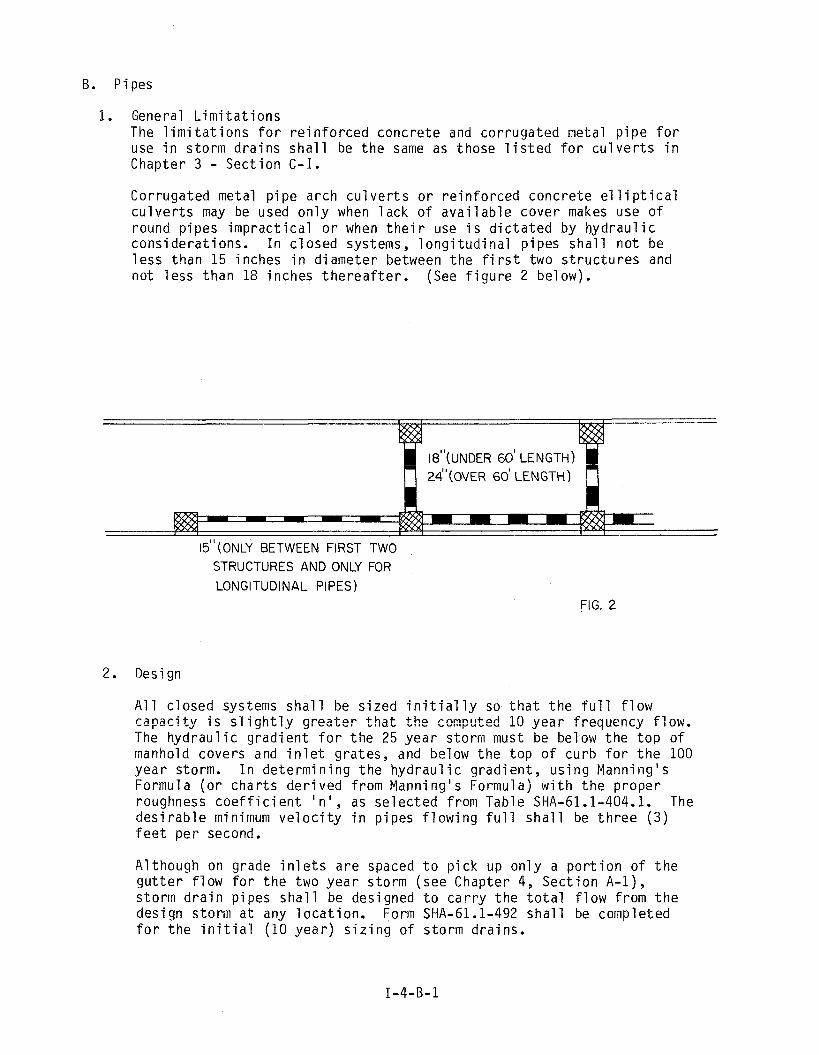
B. Pipes
1. General L i m i t a t i o n s The l i m i t a t i o n s f o r r e i n f o r c e d concre te and cor ruga ted metal p i p e f o r use i n s torm d ra i ns s h a l l be t h e sarne as those l i s t e d f o r c u l v e r t s i n Chapter 3 - Sec t ion C - I .
Corrugated metal p i pe a rch c u l v e r t s o r r e i n f o r c e d concre te e l 1 i p t i c a l c u l v e r t s may be used o n l y when l a c k o f a v a i l a b l e cover makes use of round p ipes i m p r a c t i c a l o r when t h e i r use i s d i c t a t e d by h y d r a u l i c cons idera t ions . I n c l osed systems, l o n g i t u d i n a l p ipes s h a l l no t be l e s s than 15 inches i n d iameter between t h e f i r s t two s t r u c t u r e s and no t l ess than 18 inches t h e r e a f t e r . (See f i g u r e 2 below).
I UNDER 60' LENGTH) OVER 60' LENGTH)
I~" (ONLY BETWEEN FIRST TWO STRUCTURES AND ONLY FOR
LONGITUDINAL PIPES) FIG. 2
2. Design
A l l c losed systems s h a l l be s i zed i n i t i a l l y so t h a t t h e f u l l f l o w capac i ty i s s l i g h t l y g rea te r t h a t t h e cemputed 19 y e a r f requency f lew. The h y d r a u l i c g rad ien t f o r t h e 25 yea r storm must be below t h e t o p o f manhold covers and i n l e t g ra tes , and below t h e t o p o f cu rb f o r t h e 100 y e a r storm. I n de te rm in i ng t h e hydrau l i c g rad ien t , us i ng Manning's Formul a ( o r cha r t s d e r i v e d f rom Manning' s Formula) w i t h t h e p roper roughness c o e f f i c i e n t ' n ' , as se l ec ted from Table SHA-61.1-404.1. The d e s i r a b l e minimum v e l o c i t y i n p ipes f l o w i n g f u l l s h a l l be t h r e e ( 3 ) f e e t pe r second.
A1 though on grade i n l e t s a re spaced t o p i c k up o n l y a p o r t i o n o f t h e g u t t e r f l o w f o r t h e two y e a r s torm (see Chapter 4, Sec t i on A-1), s torm d r a i n p ipes s h a l l be designed t o c a r r y t h e t o t a l f l o w f rom t h e design storrn a t any l o c a t i o n . Form SHA-61.1-492 s h a l l be completed f o r t h e i n i t i a l (10 y e a r ) s i z i n g o f s to rm dra ins .
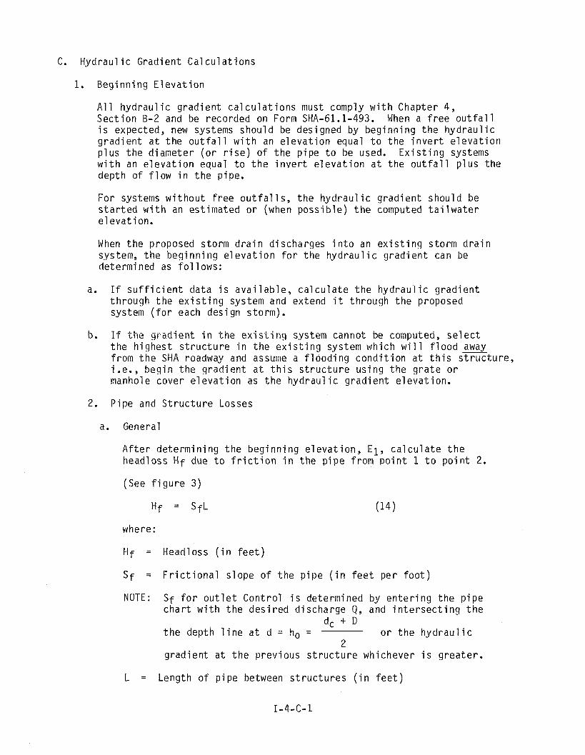
C. Hydrau l i c Grad ien t C a l c u l a t i o n s
1. B e g i n n i n g E l e v a t i o n
A1 1 hyd rau l i c g r a d i e n t c a l c u l a t i o n s must comply w i t h Chapter 4, S e c t i o n B-2 and be reco rded on Form SHA-61.1-493. When a f r e e o u t f a l l i s expected, new systems s h o u l d be des igned by b e g i n n i n g t h e h y d r a u l i c g r a d i e n t a t t h e o u t f a l l w i t h an e l e v a t i o n equal t o t h e i n v e r t e l e v a t i o n p l u s t h e d i a m e t e r ( o r r i s e ) of t h e p i p e t o be used. E x i s t i n g systems w i t h an e l e v a t i o n equa l t o t h e i n v e r t e l e v a t i o n a t t h e o u t f a l l p l u s t h e dep th o f f l o w i n t h e p ipe.
F o r systems w i t h o u t f r e e o u t f a l l s, t h e h y d r a u l i c g r a d i e n t s h o u l d be s t a r t e d w i t h an e s t i m a t e d o r (when p o s s i b l e ) t h e computed t a i l w a t e r e l e v a t i o n .
When t h e proposed s t o r m d r a i n d i scha rges i n t o an e x i s t i n g s t o r m d r a i n system, t h e b e g i n n i n g e l e v a t i o n f o r t h e h y d r a u l i c g r a d i e n t can be determined as f o l 1 ows:
a. I f s u f f i c i e n t d a t a i s a v a i l a b l e , c a l c u l a t e t h e h y d r a u l i c g r a d i e n t t h r o u g h t h e e x i s t i n g system and ex tend i t t h r o u g h t h e proposed system ( f o r each d e s i g n s to rm) .
5. I f t h e g r a d i e n t i n t h e e x i s t i n g system cannot be computed, s e i e c t t h e h i g h e s t s t r u c t u r e i n t h e e x i s t i n g system wh ich w i l l f l o o d away f rom t h e SHA roadway and assume a f l o o d i n g c o n d i t i o n a t t h i s s t r u c t u r e , i .e., b e g i n t h e g r a d i e n t a t t h i s s t r u c t u r e u s i n g t h e g r a t e o r manhole cove r e l e v a t i o n as t h e h y d r a u l i c g r a d i e n t e l e v a t i o n .
2. P i p e and S t r u c t u r e Losses
a. General
A f t e r d e t e r m i n i n g t h e b e g i n n i n g e l e v a t i o n , E l , c a l c u l a t e t h e head loss Hf due t o f r i c t i o n i n t h e p i p e f r o m p o i n t 1 t o p o i n t 2.
(See f i g u r e 3 )
where:
Hf = Head loss ( i n f e e t )
Sf = F r i c t i o n a l s l o p e o f t h e p i p e ( i n f e e t p e r f o o t )
NOTE: Sf f o r o u t l e t C o n t r o l i s de te rm ined by e n t e r i n g t h e p i p e c h a r t w i t h t h e d e s i r e d d i s c h a r g e Q, and i n t e r s e c t i n g t h e
dc +.D t h e depth l i n e a t d = ho = o r t h e h y d r a u l i c
2 g r a d i e n t a t t h e p r e v i o u s s t r u c t u r e wh ichever i s g r e a t e r .
L = Length o f p i p e between s t r u c t u r e s ( i n f e e t )

T h i s head loss i s now added t o t h e b e g i n n i n g e l e v a t i o n , €1. T h i s new e l e v a t i o n , E2, i s t h e h y d r a u l i c g r a d i e n t a t p o i n t 2. Now c a l c u l a t e t h e head loss due t o s t r u c t u r e A. The magni tude of t h e s t r u c t u r e l o s s i s dependent on t h e t y p e o f s t r u c t u r e ( i .e . i n l e t , manhole, o r bend) and t h e a n g l e between t h e i ncoming and o u t g o i n g p i p e s . It i s computed by t h e f o l l o w i n g formula .
where:
hb = Headloss ( i n f e e t )
kb = Headloss c o e f f i c i e n t (See SHA-61.1 - 408.0)
V f = F r i c t i o n a l V e l o c i t y i n t h e o u t l e t p i p e ( i n f e e t p e r second. The v e l o c i t y f o r t h e g i v e n q and d = ho)
9 = A c c e l e r a t i o n due t o g r a v i t y ( i n f e e t p e r second, p e r second).
T h i s l o s s may a l s o be de te rm ined b y t h e a p p r o p r i a t e c h a r t , The s t r u c t u r e l o s s a t a f i e l d c o n n e c t i o n i s t h e same as t h a t f o r a manhole.
HYDRAULIC
GROUND LINE
.
FIG. 3

TABLE OF Kb VALUES
ANGLE I N L E T MANHOLE BEND ANGLE I N L E T MANHOLE BEND STRUCTURE STRUCTURE
MARYLAND STATE HIGHWAY A D M I N I S T R A T I O N SHA-61.1-408.0
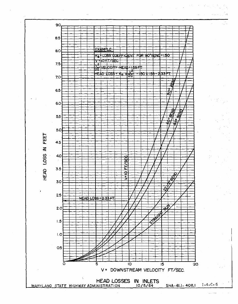
0 5 10 15 20-
V - DOWNSTREAM VELOCITY FTISEC.
HEAD LOSSES IN INLETS MARYLAND STATE HIGHWAY ADMINISTRATI ON 10/5/64 SHA-61.1- 408.1 I-4-C-

0 5 10 15 20 V = DOWNSTREAM VELOCITY FWSEC.
HEAD LOSSES IN MANHOLES MARYLAND STATE HIGHWAY ADMINIST RATION l0/5/64 SHA - 61.1 - 4083

V= DOWNSTREAM VELOCITY FT/SEC.
HEAD LOSSES IN BENDS. ( R= 2 1/2 X PIPE DIA. ) MARYLAND STATE'HIGHWAY ADMINISTRATION 10/5 /64 SHA-61.1- 408.3
I-4-C- 9 - --- ---
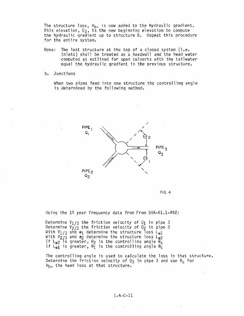
The s t r u c t u r e l o s s , Hb, i s now added t o t h e h y d r a u l i c g r a d i e n t . T h i s e l e v a t i o n , E3, i s t h e new b e g i n n i n g e l e v a t i o n t o compute t h e h y d r a u l i c g r a d i e n t up t o s t r u c t u r e B. Repeat t h i s p rocedure f o r t h e e n t i r e system.
Note: The l a s t s t r u c t u r e a t t h e t o p o f a c l o s e d system ( i . e . I n l e t s ) s h a l l be t r e a t e d as a headwal l and t h e head w a t e r computed as o u t l i n e d f o r open c u l v e r t s w i t h t h e t a i l w a t e r equal t h e h y d r a u l i c g r a d i e n t i n t h e p r e v i o u s s t r u c t u r e .
b. J u n c t i o n s
When two p i p e s feed i n t o one s t r u c t u r e t h e c o n t r o l l i n g a n g l e i s de te rm ined by t h e f o l l o w i n g method.
PIPE , Q I
PIPE
Q2
PIPE
Q3
FIG. 4
Us ing t h e 10 y e a r f requency d a t a f rom From SHA-61.1-492:
De te rm ine V1/3 t h e f r i c t i o n v e l o c i t y o f i n p i p e 3 Determine V2/3 t h e f r i c t i o n v e l o c i t y o f Q2 i n p i p e 3 W i t h V1/3 and e l d e t e r m i n e t h e s t r u c t u r e l o s s L e i W i t h V2/3 and e2 de te rm ine t h e s t r u c t u r e l o s s Le2 I f Le2 i s g r e a t e r , 82 i s t h e c o n t r o l l i n g a n g l e Q c I f L e i i s g r e a t e r , 8 1 i s t h e c o n t r o l l i n g a n g l e 8,
The c o n t r o l l i n g a n g l e i s used t o c a l c u l a t e t h e l o s s i n t h a t s t r u c t u r e . Determine t h e f r i c t i o n v e l o c i t y o f Q3 i n p i p e 3 and use Oc f o r Hb, t h e head l o s s a t t h a t s t r u c t u r e .
3. General L i m i t a t i o n s
When t h e h y d r a u l i c g r a d i e n t i s be ing computed, t h e d e s i g n e r must have a v a i l a b l e e i t h e r a p r o P i l e o f t h e system o r a l i s t o f i n v e r t e l e v a t i o n s and s t r u c t u r e f l o o d i n g e l e v a t i o n s a g a i n s t wh ich each computed g r a d i e n t e l e v a t i o n may be checked.
A f t e r comput ing t h e f r i c t i o n l o s s i n a s e c t i o n o f p i p e and d e t e r m i n i n g t h e h y d r a u l i c g r a d i e n t e l e v a t i o n a t t h e upst ream end o f t h a t s e c t i o n , t h e d e s i g n e r shou ld a l s o compute t h e normal dep th e l e v a t i o n a t t h i s p o i n t . When a p i p e i s f l o w i n g l e s s t h a n f u l l ( n o t under p r e s s u r e ) t h e e l e v a t i o n and t h e w a t e r s u r f a c e e l e v a t i o n a t any p o i n t a r e t h e same. T h i s depth o f f l o w i s c a l l e d t h e normal depth.
The normal dep th e l e v a t i o n i s t h e normal dep th p l u s t h e i n v e r t e l e v a - t i o n a t t h a t p o i n t . I f t h e computed h y d r a u l i c g r a d i e n t e l e v a t i o n i s l o w e r t h a n t h e normal dep th e l e v a t i o n , t h e g r a d i e n t must be a d j u s t e d t o t h e normal dep th e l e v a t i o n a t t h a t p o i n t .
Each t i m e a s t r u c t u r e l o s s i s computed and added t o t h e h y d r a u l i c g r a d i e n t , t h e r e s u l t i n g g r a d i e n t e l e v a t i o n shou ld be compared t o t h e f l o o d i n g e l e v a t i o n f o r t h e s t r u c t u r e . O f course, s t r u c t u r e s w i t h o u t su r face access cannot f l o o d and need n o t be checked. When t h e g r a d i e n t exceeds t h e p r e s c r i b e d l i m i t s , t w o p r a c t i c a l measures a r e a v a i l a b l e t o reduce t h e g r a d i e n t e l e v a t i o n w i t h o u t chang ing a1 ignment and/or s t r u c - t u r e t ype :
a. Lower t h e e n t i r e sys tem o r i f one s e c t i o n o f p i p e f l o w s a t normal depth , l o w e r t h e s e c t i o n o f t h e system above t h a t p ipe .
b. I n c r e a s e t h e c a p a c i t y o f t h e p i p e i m m e d i a t e l y below t h e f l o o d i n g s t r u c t u r e by i n c r e a s i n g s i z e and/or dec reas ing roughness c o e f f i - c i e n t o r , when t h i s i s n o t s u f f i c i e n t , by use o f m u l t i p l e p ipes .
When i t i s necessary t o i n c r e a s e p i p e s i z e , c a r e must be t a k e n t o a v o i d t h e c r e a t i o n o f a f u t u r e maintenance prob lem r e s u l t i n g f r o m d i s c h a r g i n g a p i p e o f g r e a t e r c r o s s s e c t i o n i n t o a p i p e o f l e s s e r c r o s s s e c t i o n . P i p e s i z e ad jus tmen ts may have t o be made down- stream, s e v e r a l s e c t i o n s below t h e one a t wh ich f l o o d i n g i s expe- r i e n c e d i n o r d e r t o keep t h e s i z e s i n p r o p e r sequence. T h i s i s 7 -----I ~ d r - y e t y a t r i a l and e r r o r procedure. i f t h e s e measures a r e i n s u f - f i c i e n t o r i m p r a c t i c a l , t h e d e s i q n e r shou ld i n v e s t i g a t e chang ing a l i gnmen t i n o r d e r t o l o w e r t h e g r a d i e n t .
PART I __ _---
CHAPTER 5 STORM HATER MANAGEMENT
A. Objective
The concept of storm water management has been adopted t o control the r a t e of runoff from any watershed. To be e f f e c t i v e , i t must be pract iced by a l l p a r t i e s , including both public agencies and p r iva te developers, who a r e engaged in changing land use.
The goal is t o s t a b i 1 i z e t h e r a t e of runoff which each subsequent .downstream property owner must accept and convey through h i s property, t o prevent any increase i n t h e f loodpla in , t o prevent channel erosion and property damage, When achieved, i t should keep e x i s t i n g problems from worsening and prevent new problems which otherwise would have developed.
The S t a t e Highway Administration has a two-fold i n t e r e s t i n the concept of s t o m water management.
First, a s an Agency engaged i n changing e x i s t i n g land use by the construc- t ion of highways, i t is responsib le for t h e construct ion of drainage and storm water management f a c i l i t i e s t h a t w i l l comply w i t h S t a t e laws and regul at ions,
Second, a s a downstrean property owner, t h e S t a t e Highway Administration must concern itself d t h t h e a c t i v i t i e s o f upstream developers whose increased runoff could endanger t h e highway and 9 t s users,
For i l l u s t r a t i v e information on t h e following sec t ion see f i g u r e s 5 and 6,

3. Projects Requiring Management
Storm water management is required on a1 1 State flighway' Ami nistration projects where an increase i n t h e discharge rate from 'tfie right of way would result from:
1. An increase i n the runoff coefficient o r runoff curve number,
2. A concentration of runoff a t a given point.
3. An unavoidable diversion of runoff from another watershed-
4, A shortening of the t i m e concentration.
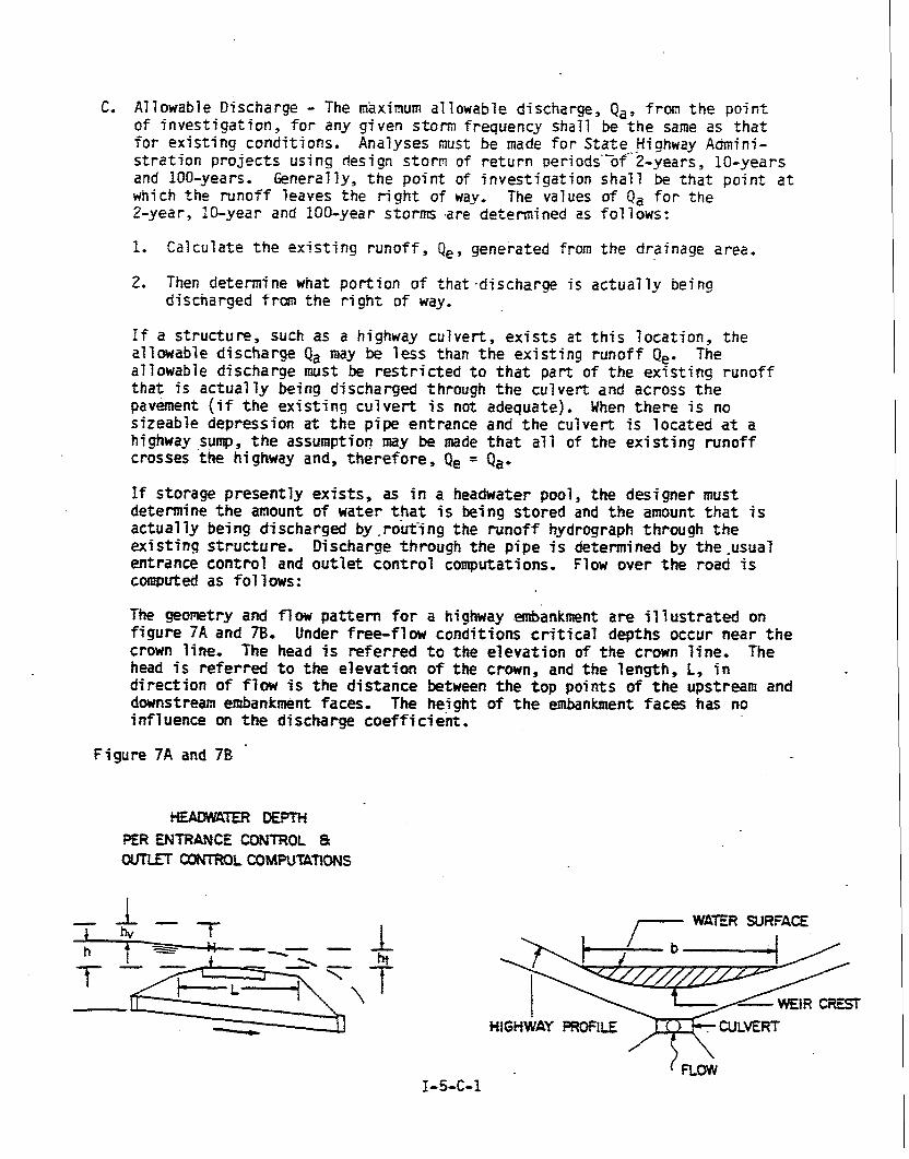
C. Allowable Discharge - The maximum al lowable discharge, Qa, from t h e po in t of i n v e s t i g a t i o n , f o r any given s torm frequency sha l l be t h e same a s t h a t f o r e x i s t i n g condi t ions . Analyses must be made f o r S t a t e ffighway Admini- s t r a t i o n p r o j e c t s us ing design s torm of r e t u r n periodi-of-2-years, l o o y e a r s and 100-years. Generally, t h e po in t of i n v e s t i g a t i o n s h a l l be t h a t po in t a t which t h e runoff leaves the r i g h t of way, The values of Q, f o r t h e 2-year, 10-year and 100-year s torms .are determined as f o l lows:
I. Calcu la te t h e e x i s t i n g r u n o f f , Qe, generated from t h e drainage a rea .
2. Then determine what po r t i on of t h a t .d i scharge is a c t u a l l y being discharged f ran t h e r i g h t of way.
f f a s t r u c t u r e , such as a highway cu lve r t , e x i s t s a t t h i s l o c a t i o n , t h e allowable d i s cha rge Qa may be less than t h e e x i s t i n g runoff Qe. The al lowable d i s cha rge must be restricted t o t h a t part of t h e e x i s t i n g runoff t h a t is a c t u a l l y being d ischarged through t h e cu lve r t and ac ros s t h e pavement ( i f t h e e x i s t i n g c u l v e r t is not adequate) . When t h e r e is no s i z e a b l e depress ion a t the p ipe en t r ance and t h e cu lve r t is loca t ed a t a highway sunrp, t h e assumptior! may be made t h a t a l l of t h e e x i s t i n g runoff c rosses ' the highway and, t h e r e f o r e , Qe = Q,,
If s to rage p r e s e n t l y e x i s t s , as i n a headwater pool, t h e des igne r must determine t h e amount of water t h a t is being s t o r e d and t h e amount t h a t is ac tua l ly being discharged by , rout-i ng the runoff hydrograph through t h e e x i s t i n g s t r u c t u r e , Discharge through t h e p i p e is determined by t h e .usual en t rance c o n t r o l and o u t l e t c o n t r o l computations. Flow over t h e road is computed a s fof 1 ows :
The geometry and f l o w p a t t e r n f o r a highway embankment a r e i 7 l u s t r a t e d on f i g u r e 7A and 7B. Under free-fl w condi t ions c r i t i c a l dep ths occur near t h e crown line. The head is r e f e r r e d t o the e l e v a t i o n of t h e crown l i n e , The head is r e f e r r e d t o the e l e v a t i o n o f the crown, and the l eng th , L, i n d i r e c t i o n of f low is t h e d i s t a n c e between t h e t o p po in t s of t h e upstream and downstream embankment faces. The height of t h e embankment f a c e s has no i n f l uence on t h e d i scharge coeff i ci&t ,
Figu re 7A and 78
HEADWTER DEPTH PER WTRANCE CONTROL 8 OUTLET CONTROL COMPUTATIONS
1- WATER SURFACE
WEiR CREST HIGHWAY PROfllE . CULVERT
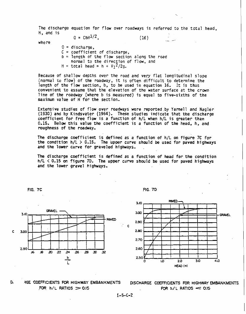
The discharge equation f o r flow over roadways is referred t o the t o t a l head, H, and is
Q = ~ b ~ 3 / 2 , (16) __ __-- where
Q = discharge, C = coef f i c i en t of discharge, b = length of t h e flow section along t h e road
normal t o the d i rec t ion of flow, and H = t o t a l head = h + v ~ ~ / z ~ .
Because of shallow depths over t h e road and ve-ry f l a t longitudinal s l o p e (normal t o fiowj of the roadway, i t is .often d i f f i c u l t t o determine t h e length of t h e flow sect ion , b, t o be used i n equation 16, I t is thus convenient t o assume t h a t t h e elevation of the water surface a t t h e crown l i n e of the roadway (where b is measured) is equal t o f ive-s ix ths of t h e maximum value of H f o r the sect ion.
Extensive studies of flow over roadways were reported .by Yarnell and Nagler (1930) and by Kindsvater (1964). These s t u d i e s indica te t h a t t h e d ischarge coe f f i c i en t f o r f r e e flow is a function of h/F when h/L is grea ter than 0.15. 'Below t h i s value t h e coeff ic ient is a function of the head, h, and roughness of t h e roadway,
The d i s c h a q e coe f f i c i en t is defined as a function of h/L on f i g u r e 7C f o r t h e condition h/L > 0.15. The upper curve should be used fo r paved highways and the lower curve f o r graveled highways, .
The discharge coe f f i c i en t is defined as a function of head f o r t h e condi t ion tt/L < 0.15 on figure ?I). The upper curve should be used fo r paved highways and t h e l ower gravel highways.
GRAVEL - FIG. 70
AGE COEFRCIENTS FOR HIGHWAY EMBANKMENTS DISCHARGE COEfFiCI WTS FOR HIGHWAY EMBANKMENTS. .FOR h/ L RATIOS 7 0.15 FOR h/ L RATIOS L= 0.15
I- 5-C-2
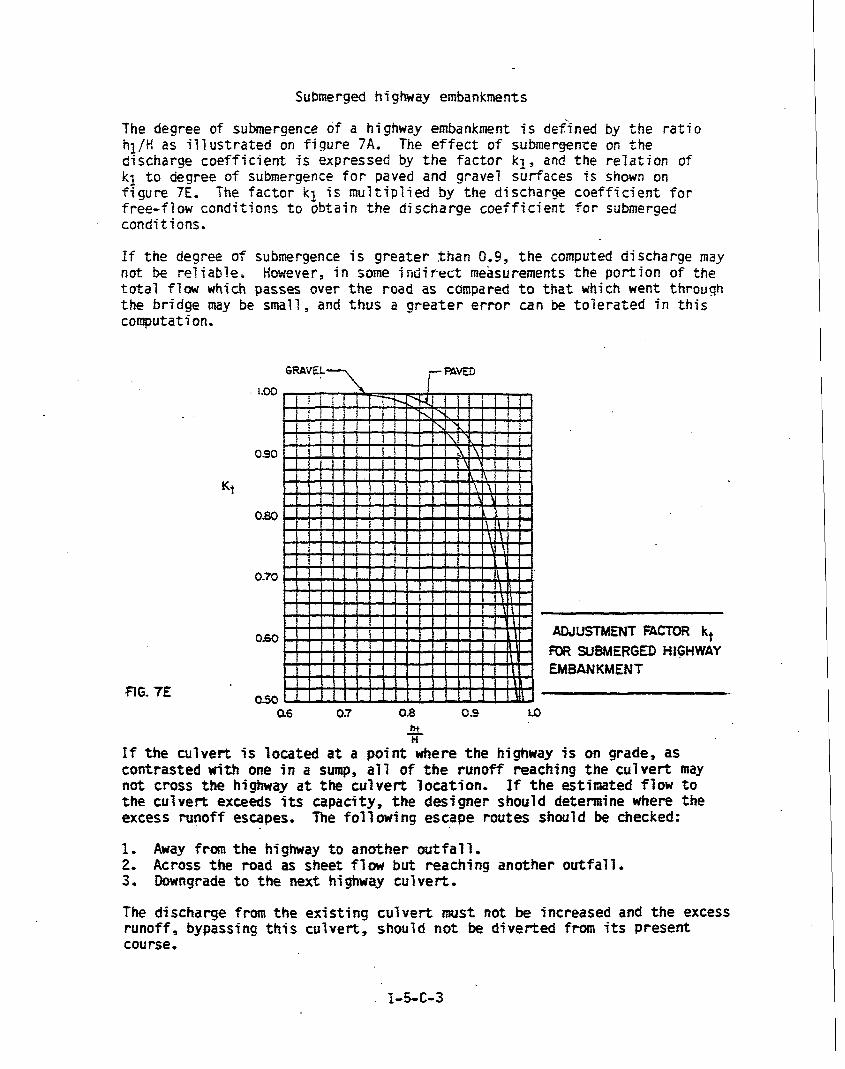
Submerged highway embankments
The degree of submergence df a highway embankment i s defined by t h e r a t i o hl/H a s i l l u s t r a t e d on f i g u r e 7A. The e f f e c t of submergence on t h e discharge c o e f f i c i e n t is expressed by t h e f a c t o r k l , and the r e l a t i o n of k l t o degree of submergence f o r paved and gravel sur faces is shown on f i g u r e 7E, The f a c t o r k l is mul t ip l i ed by the discharge c o e f f i c i e n t f o r free-f low condi t ions t o obta in t h e d ischarge c o e f f i c i e n t f o r submerged condit ions.
I f t h e degree of submergence i s g r e a t e r t h a n 0.9, t h e computed di sciiarge may not be re1 iable* However, f n sme int i? rect measurements t h e port ion of t h e t o t a l flaw which passes over the road as compared t o t h a t which went through the bridge may be small , and t h u s a g r e a t e r e r r o r can be t o l e r a t e d i n this computation,
1 - 0 0
090
KY
oso
0-70
0.60 ADJUSTMENT FACTOR kt FUR SUBMEPGED HIGHWAY EMBANKMENT
RG. 7E 050 46 07 0.8 09 LO
2L H
If t h e c u l v e r t is loca ted a t a p o i n t where t h e highway is on grade, as con t r a s t ed with one i n a sump, a7 7 of t h e runoff reaching t h e c u l v e r t may not cross t h e highway a t t h e c u l v e r t l o c a t i o n , I f t h e est imated flow t o t h e c u l v e r t exceeds its capac i ty , t h e d e s i g n e r should determine where t h e excess runoff escapes, The fo17 w i n g e scape rou te s should be checked:
1, Away from the higbway t o a n o t h e r o u t f a l l . 2, Across t h e road a s sheet flw but reaching ano the r o u t f a l l . 3. Downgrade t o t h e next higbway cu lve r t .
The discharge from t h e existing c u l v e r t must not be increased and t h e excess runoff , bypassing t h i s cu lve r t , should not be d i v e r t e d from its Presen t course .

D. Required S torage
1, Pre l iminary Design
The actiial s t o r a g e volume required t o compensate f o r any inc rease i n runoff can only be determined by a t r i a l and e r r o r procedure of rou t ing a runoff hydrograph through a management s t r u c t u r e * For prel iminary des ign , t h e required s t o r a g e nay be es t imated by one (1 ) of the fol lowing methods:
a, Uhsn d e s i g n i n g by t h e Rational Method.
f o r each s torm frequency
where:
. . S = required s t o r a g e ( in cub ic f e e t ) t, = time of concent ra t ion ( i n seconds) ( e x i s t i n g ) Qp = proposed geak d ischarge ( i n c f s ) Q, = a l lowable r e l e a s e r a t e ( i n c f s )
b. When designing by t h e SCS TR-55 Method,
V,, t h e volume of s to r age , i s detemined by the method ou t l i ned i n Chapter 7 o f TR-55.
c. When using t h e TR-20 Method.
V,, t h e volume o f s t o r a g e , may be es t imated by running the sub- r o u t i n e "RUNOFF" f o r t h e watershed f o r e x i s t i n g and proposed condi t ions . U t i l i z i n g t h e ou tput op t ion of volume of runoff, t h e i n c r e a s e due t o cons t ruc t ion w i l l be the d i f f e r e n c e i n t h e s e two vat ues,
NOTE: Each of t h e s e methods is for pre l iminary e s t ima te s o f s t o r a g e only, The f i n a l volume depends on t h e i n t r i c a t e i n t e r - a c t i o n o f t h e shape and o r i e n t a t i o n of t h e f a c i l i t y itself and con f igu ra t i on of t h e cont ro l s t r u c t u r e . F4na1 des ign can only be accomplished through t r i a l and e r r o r by rou t ing t h e runoff hydro- graph through t h e f a c i l i t y .
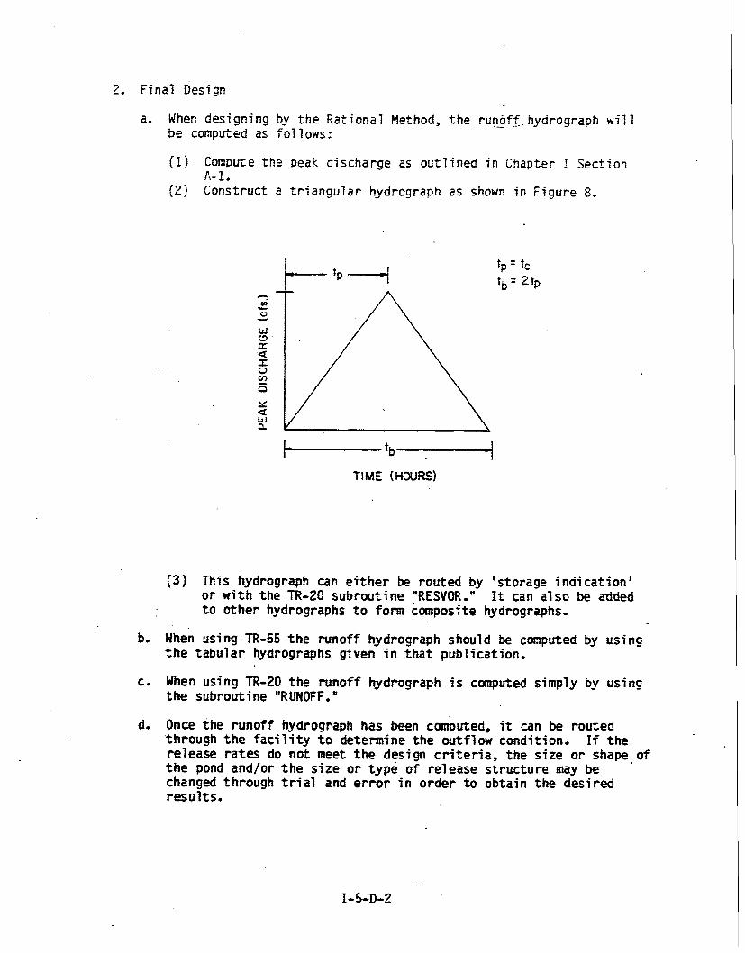
2, Final Design
a, When designing by t h e Rational Method, t h e runoff. . - hydrograph wi17 be computed as fo l 1 ows :
(1) Compute the peak discharge as outl ined i n Chapter I Section A- 1.
(2) Construct a t r i a n g u l a r hydrograph as shown i n Figure 8.
(3) This hydrograph can e i t h e r be routed by 's torage ind ica t ion ' o r w i t h the TR-20 subrout ine "ESVOR," I t can a l s o be added t o o the r hydrographs t o form composite hydrographs-
b. hen using.TR-55 t h e nmoff hydmgraph should be computed by using t h e t a b u l a r hydrographs given i n t h a t publi'cation,
c, When using TR-20 the runoff hydrograph is computed simply by using t h e subroutine "RUNOFF,"
do Once the runoff hydrograph has been computed, i t can be routed through t h e f a c i l i t y t o determine t h e outflow condit ion- If t h e r e l ease rates do not meet t h e design c r i t e r i a , t h e size o r shape.of t h e pond and/or t h e size o r t y p e of r e l ease s t r u c t u r e may be changed through t r i a l and error i n o rde r t o obtain t h e des i red resu l t s .
E. Detention ~ a c i l i t ~ Types
I. Highway Projec ts _ _ _ _ - -
Detention areas adjacent t o S ta te Highway Admini s t r a t i o n culver ts o r grassed areas i n medians o r interchanges wi l l probably prove t o be the most p rac t i ca l and economical means of meeting storage requirements, although i n some cases, underground s torage may be necessary.
Detention may be accompl i s h e d upstream or downstream f born t h e highway. P rac t i ca l considerat ions, such as t h e amount of storage requi red, cos t o r a v a i l a b i l i t y of t h e r i g h t of way o r easement, cos t of the f a c i l i t y and t h e amount of maintenance needed t o assure r e l i a b l e operation w i l l a l l influence t h e locat ion . When a s i z e a b l e amount of s torage capacity is required, s torage upstream from the highway w i l l usually prove more p r a c t i c a l s ince t h e highway embankment wi17 serve t o confine t h e water.
The s torage capacity required t o manage a 100 yea r frequency s t o m must be provided within t h e S t a t e Highway Administration right-of-way o r easement and t h e maximum s torage e leva t ion must not exceed t h e lowest pavement edge elevation.
The S t a t e Highway Administration m u s t acquire any area on which i t is responsible f o r r a i s i n g t h e 100 y e a r f lood plane elevation.
The C h i e f , Bureau of Highway Design should be consulted t o de ternine which f a c i l i t i e s should be fenced t o p ro tec t t h e public.
2, Other P ro jec t s
For l a r g e amounts of s to rage , surface s to rage is a prac t ica l and economial solut ion. If space is a c r i t i c a l f a c t o r , expensive under- ground s torage may be required, If underground s to rage is used, t h e chamberfs) nus t be properly vented t o f i l l t o i ts designed capacity,
For small amaunts of s to rage , parking ' lots or rooftops may provide adequate .s torage volumes,
If s t o n e f i l l e d p i t s a r e t o be used, some means of pos i t ive drainage must be provided, Exceptions t o t h i s r u l e w i l l be considered f o r p i t s which are drained by i n f i l t r a t i o n only; however, t h e designer must s u h i t de ta i l ed support ing canputat ions concerning t h e action of the water t a b l e and s o i l permeability. In either case, t h e S.H.A. w i l l only cons ider 33% of t h e volume of voids t o - be ava i l ab le f o r s to rage unless fil ter c lo th l i n i n g is provided; i n which case 100% of t h e volume o f voids may be considered a v a i l a b l e f o r storage.
When su r face s torage is t o be impounded aga ins t the highway embankment, the a v a i l a b l e s to rage must be computed a s indicated in f igure 9.
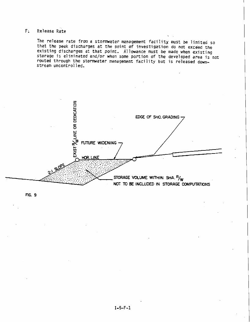
F. Release ate The release rate from a stormwater management facil igr must be 1 imited so t h a t the peak discharges a t the point of investigation do not exceed the existing discharges a t t h a t point. A1 lowance must be made when existing storage is eliminated and/or when some portion of the developed area is not routed through the stormwater management faci 1 i ty but i s released down- stream uncontrol l ed.
-I
FUTURE WIDENING 7
EDGE Of SHO. GRADING 7
1
STORAGE VOLME WITHtN %A. R/, NOT TO BE INCLUDED IN STORAGE COMPUIATtONS
G, Control Structures
In general, control structures can be any arrangementf-simple culverts or "orifice and weir" structures which will provide the multiple stage re1 ease required for the 2 year, 10 year and the 100 year storms.
When simple pipes are used, size, roughness and slope should be selected so t h a t culvert operation (either entrance or outlet control ) w i 71 not discharge more t h a n the allowable release rate when operating under the head resulting from maximum storage.
A transverse highway culvert may not be used as a control structure if i t does not provide the proper release rates for all storms. In these cases, the proper release rates will be achieved by a suitable orifice and/or weir type control structure, Orif ice and weir structures should be designed using the fo1 lowing formulas:
For the Orifice, See Figure 10 next page.
Q = ca, where:
Q = Discharge (in cubic feet per second) C = a Constant (Ref. 19, Appe.ndix 2)
a = the area of the orifice ( i n square feet) g = the acceleration due to gravity (in feet per second, per second) h = the head measured from the water surface to the center of the
orifice ( i n feet)
Values of "C" w i l l be approximately 0~60 .
However, i n most release structures, the orifice will be partially or f u l l y submerged, The same formula i s used except the "ha i s the difference i n water surface elevations. In a1 7 cases, King 's "Handbook of Hydraul ic" should be consulted for tabulated values of "C" to f i t the particular orifice design,
For t h e weir, t h e usual design approximates that of a sharp crested weir.
One Formula for which is: See Figure 10 next page
Q = 3-33 1~312 where:
(19)
Q = discharge ( i n cubic feet per second) L = length of the weir ( i n feet) H = the head ( i n feet)
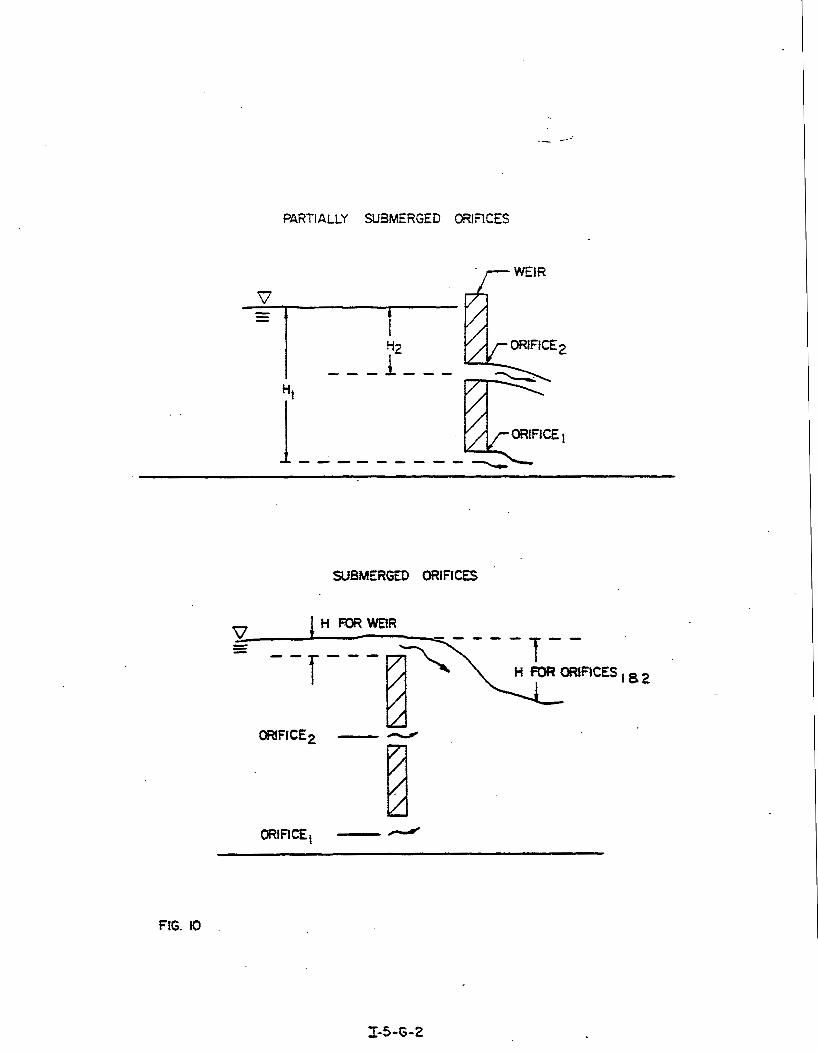
PARTIALLY SUBMERGED ORIFICES
WEIR
SUBMERGED ORlFlCfS
- - - - - g*?TXv- H FOR ORIFICES ,a*
ORIFICE2 -
I ORIFICEt --
FIG. I0
PART I .- .-- -
C H A P T E R 6 KARST TOPOCXAPHY
Some areas, mainly i n Frederick and Washington counties, have underlying limestone s t r a t a i n which sizeable subsurface channels have been produced by the natural erosive forces of water. Considerable areas may discharge t h e i r surface runoff into these channels via ."sinkhe!es" thtts redstcing the expected flow of surface drainage through, normal surf ace .water course. Since these channels are i r regular i n shape and the i r subsurface route i s unpredictable, t h e i r capacity cannot be estimated w i t h any degree of accuracy.

5. Sinkholes a s O u t f a l l s
When cons t ruc t ion o r devel opment a c t i v i t i e s occur i n these areas these channels may be destroyed. Therefore, t h e designer m'tEfconsider t h e i r operation t o be only temporary and i f they a r e t o form a part of h i s drainage scheme, an a1 t e r n a t e design m u s t be provided. If the designer e l ec t s t o use a s inkhole as h i s o u t f a l l , he should a l s o design t h e remainder of the dra inage f a c i l i t i e s w h i c h will be required t o car ry t h e runoff t o an adequate s u r f a c e watercourse i n t he event of f a i l u r e of the underground natural drainage and acquire t h e r igh t of way o r easement which would be required f o r t h e cons t ruct ion ,