higher national diploma (hnd) welding and … · 1.2 higher national diploma (hnd) programme: ......
TRANSCRIPT

NATIONAL BOARD FOR TECHNICAL EDUCATION, KADUNA.
HIGHER NATIONAL DIPLOMA (HND)
WELDING AND FABRICATION TECHNOLOGY
CURRICULUMS AND COURSE SPECIFICATIONS

2
GENERAL INFORMATION Goal of Welding & Fabrication Technology Programme 1.0 The programme is intended to impart theoretical knowledge and practical skill to students on engineering design practice, planning, management, operation and maintenance of Welding & Fabrication Technology Programme system and equipment suitable for a technician. 1.1 General Entry Requirements: (a) NATIONAL DIPLOMA (ND) The general entry requirement for the ND programme is General Certificate of Education (GCE) Ordinary Level, or the SeniorSecondary School Certificate (SSSC) with credit passes in four relevant subjects. The relevant subjects are: Mathematics, Physics, Chemistry and one other subject from Metal Work, Wood Work, Technical Drawing, Basic Electronics, Economics, Statistics, English Language, Additional Mathematics plus a pass in English Language at not more than two sittings. (b) Passes at credit level in the four relevant subjects at the Preliminary National Diploma Examination. (c) The National Technical Certificate (NTC) with credit passes in the four relevant subjects and a pass in English Language. 1.2 Higher National Diploma (HND) Programme: The general entry requirements for the HND programme include: (a) all the requirements for admission into the ND programme as stated above; (b) a minimum of lower credit pass (CGPA 2.50 and above) in the cognate ND examination; and (c) a minimum of one year cognate work experience. In exceptional cases, ND diplomates with a pass (CGPA 2.00-2.49) in the ND Examination that had two or more years of cognate experience in the specific field may be considered for admission into the HND programme.

3
2.0 Curriculum: 2.1 The curriculum of all ND and HND programmes consist of four main components. These are: i) General Studies/Education ii) Foundation Courses iii) Professional Courses iv) Supervised Industrial Work Experience Scheme (SIWES) 2.2 The General Education Component shall include courses in: Art and Humanities- English Language, Communication, History. Social Studies- Citizenship (the Nigerian Constitution) Political Science, Sociology, Philosophy, Geography, Enterpreneurship Studies. 2.3 The General Education component shall account for not more than 15% of total contact hours for the programme. 2.4 Foundation Courses include courses in Mathematics, Pure Science, Technical Drawing, Descriptive Geometry, etc. The number of hours will be about 10-15% of the total contact hours. 2.5 Professional Courses are courses which give the student the theory and practical skills he needs to practice his field of calling at the technician/technologist level. These may account for between 60-70% of the contact hours. 2.6 Student Industrial Work Experience Scheme (SIWES) shall be taken during the long vacation following the end of the second semester of the first year. See details of SIWES at paragraph 7.0. 3.0 Curriculum Structure: 3.1 ND Programme

4
The structure of the ND programme consist of four semester of classroom, laboratory and workshop activities in the college and a semester (3-4 months) of Student Industrial Work Experience Scheme (SIWES). Each semester shall be of 17 weeks of duration made up as follows: 15 contact weeks of teaching, i.e. recitation, practical exercises, quizzes, test, etc; and 2 weeks for examinations and registration. SIWES shall take place at the end of the second semester of the first year. 3.2 HND Programme: The structure of the programme is similar to that of the ND save that the SIWES at the end of the first year is not compulsory. 4.0 ACCREDITATION Each programme offered either at the ND or HND level shall be accredited by the NBTE before the diplomates can be awarded either of the two diploma certificates. Details about the process of accrediting a programme for the award of the ND or HND are available from the Executive Secretary, Programme Division, National Board for Technical Education, Plot B Bida Road, P.M.B. 2239, Kaduna, Nigeria. 5.0 Conditions for the Award of the ND/HND: Institutions offering accredited programmes will award will award the National Diploma to candidates who successfully completed the programme after passing prescribed course-work examinations, diploma project and the supervised industrial work experience. Such candidates should have completed a minimum of between 72 and 80 semester credit units. 6.0 Guidance Note for Teachers Teaching the Programme: 6.1 The new curriculum is drawn in unit courses. This is in keeping with the provisions of the National Policy on Education which stress the need to introduce the semester credit units which will enable a student who so wish to transfer the units already completed in an institution of similar standard from which he is transferring.
5
6.2 In designing the units, the principle of the modular system by product has been adopted, thus making each of the professional modules, when completed provides the student with technician operative skills, which can be used for employment purposes. 6.3 As the success of the credit unit system depends on the articulation of programmes between the institution and industry, the curriculum content has been written in behavioural objectives, so that it is clear to all the expected performance of the student who successfully completed some of the courses or the diplomates of the programme. There is a slight departure in the presentation of the performance based curriculum which requires the conditions under which the performance are expected to be carried out and the criteria for the acceptable levels of performance. It is a deliberate attempt to further involve the staff of the department teaching the programme to write their own curriculum stating the conditions existing in their institution under which the performance can take place and to follow that with the criteria for determining an acceptable level of performance. Departmental submission on the final curriculum may be vetted by the Academic Board of the institution. Our aim is to continue to see to it that a solid internal evaluation system exists in each institution for ensuring minimum standard and quality of education in the programmes offered throughout the polytechnic system. 6.4 The teaching of the theory and practical work should, as much as possible, be integrated. Practical exercises, especially those in professional courses and laboratory work should not be taught in isolation from the theory. For each course, there should be a balance of theory to practice in the ratio of 50:50 or 60:40 or the reverse. 7.0 GUIDELINES ON SIWES PROGRAMME. 7.1 For the smooth operation of the SIWES the following g guidelines shall apply: Responsibility for placement of students a) Institutions offering the ND programme shall arrange to place the students in industry. by April 30 of each year, six copies of the master list showing where each student has been placed shall be submitted to the Executive Secretary, NBTE which shall in turn, authenticate the list and forward it to the Industrial Training Fund, Jos. b) The Placement Officer should discuss and agree with industry on the following:

6
i) a task inventory of what the students should be expected to experience during the period of attachment. It may be wise to adopt the one already approved for each field. ii) the industry-based supervisor of the students during the period, likewise the institution based supervisor. iii) the evaluation of the student during the period. It should be noted that the final grading of the student during the period of the attachment should be weighted more on the evaluation by his industry-based supervisor. 7.2 Evaluation of students during the SIWES In the evaluation of the student, cognizance should be taken of the following items: a) Punctuality b) Attendance c) General Attitude to Work d) Respect for authority e) Interest in the field/technical area f) Technical competence as a potential technician in his field. 7.3 Grading of SIWES To ensure uniformity of grading scales, the institution should ensure that the uniform grading of students’ work which has been agreed to by all polytechnics is adopted. 7.4 The Institution Based supervisor The institution-based supervisor should initial the log book during each visit. This will enable him to check and determine to what extent the objective of the scheme are being met and to assist students having any problems regarding the specific assignments given to them by their industry-based supervisor. 7.5 Frequency of visit Institution should ensure that students placed on attachment are visited within one month of their placement. Other visits shall be arranged so that: (1) there is another visit six weeks after the first visits; and (2) a final visit in the last month of the attachment. 7.6 Stipends for Students in SIWES

7
The rate of stipend payable shall be determine from time to time by the Federal Government after due consultation with the Federal Ministry of Education, the Industrial Training Fund and the NBTE. .7.7 SIWES as a Component of the Curriculum The completion of SIWES is important in the final determination of whether the student is successful in the programme or not. Failure in the SIWES is an indication that the student has not shown sufficient interest in the field or has no potential to become a skilled technician in his field. The SIWES should be graded on a fail or pass basis. Where a student has satisfied all other requirements but failed SIWES, he may only be allowed to repeat another four months SIWES at his own expense. National Board for Technical Education Kaduna.

8
1ST SEMESTER: HND I Course Code Course Title L T P CU CH GNS 311 Engineer in Society 2 - - 2.0 2.0 MTH 311 Advanced Algebra 2 - - 2.0 2.0 ICT 201 Computer Aided Design - - 3 3.0 3.0 MEC 312 Engineering Design 1 2 - 3.0 3.0 MEC 301 Strength of Materials 2 - 3 5.0 5.0 WEC 310 Advanced Welding Metallurgy I 2 - - 2.0 2.0 WEC 311 Advanced Welding Technology I 2 - 3 5.0 5.0 WEC 312 Advanced Weld Design 1 - 3 4.0 4.0 WEC 313 Pipe Work Technology 1 - 3 4.0 4.0 TOTAL 13 2 15 30.0 30.0 2ND SEMESTER: HND I Course Code Course Title L T P CU CH GNS 413 Industrial Management 2 - - 2.0 2.0 MTH 312 Advanced Calculus 2 - - 2.0 2.0 MEC 302 Structural Analysis 2 - - 2.0 2.0 MEC 323 Fluid Mechanics 2 - 2 4.0 4.0 WEC 320 Advanced Welding Metallurgy II 2 - 3 5.0 5.0 WEC 321 Advanced Welding Technology II 2 - 3 5.0 5.0 WEC 322 Corrosion Technology* 2 - - 2.0 2.0 WEC 323 Weld Inspection and Control I. 1 - 3 4.0 4.0 MEC 405 Thermodynamics 2 - 3 5.0 5.0 TOTAL 17 - 14 31.0 31.0
9
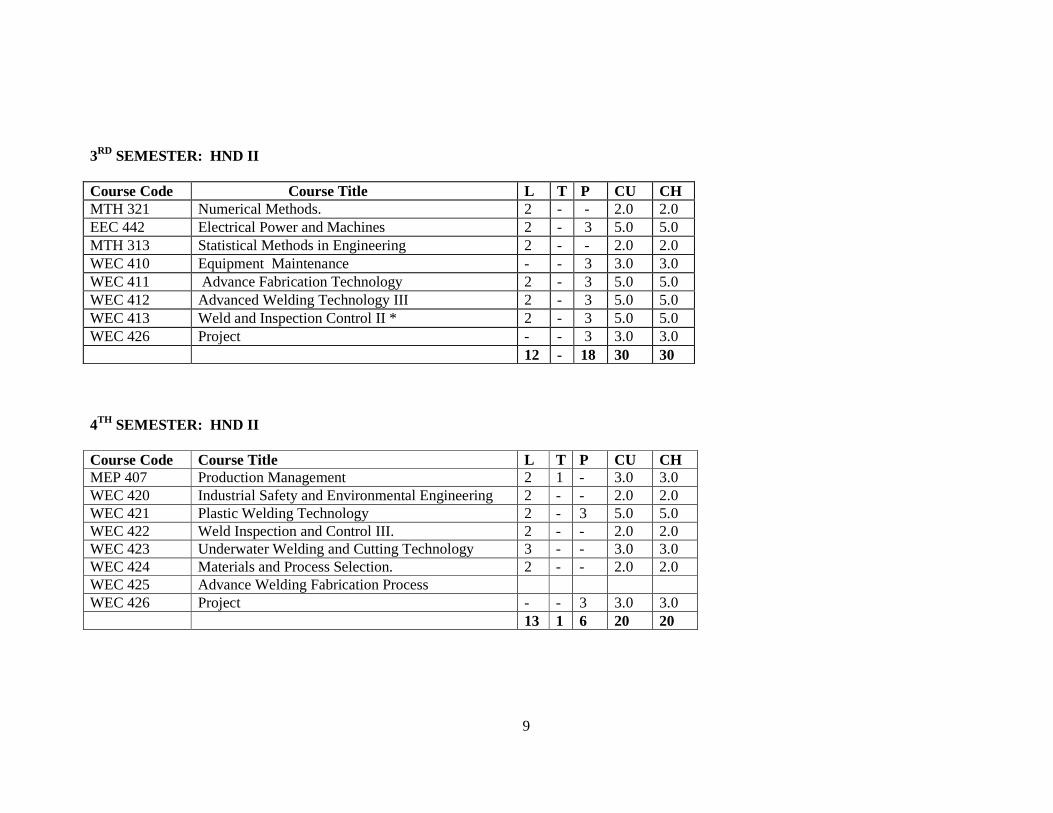
3RD SEMESTER: HND II Course Code Course Title L T P CU CH MTH 321 Numerical Methods. 2 - - 2.0 2.0 EEC 442 Electrical Power and Machines 2 - 3 5.0 5.0 MTH 313 Statistical Methods in Engineering 2 - - 2.0 2.0 WEC 410 Equipment Maintenance - - 3 3.0 3.0 WEC 411 Advance Fabrication Technology 2 - 3 5.0 5.0 WEC 412 Advanced Welding Technology III 2 - 3 5.0 5.0 WEC 413 Weld and Inspection Control II * 2 - 3 5.0 5.0 WEC 426 Project - - 3 3.0 3.0 12 - 18 30 30 4TH SEMESTER: HND II Course Code Course Title L T P CU CH MEP 407 Production Management 2 1 - 3.0 3.0 WEC 420 Industrial Safety and Environmental Engineering 2 - - 2.0 2.0 WEC 421 Plastic Welding Technology 2 - 3 5.0 5.0 WEC 422 Weld Inspection and Control III. 2 - - 2.0 2.0 WEC 423 Underwater Welding and Cutting Technology 3 - - 3.0 3.0 WEC 424 Materials and Process Selection. 2 - - 2.0 2.0 WEC 425 Advance Welding Fabrication Process WEC 426 Project - - 3 3.0 3.0 13 1 6 20 20

10
PROGRAMME: HIGHER NATIONAL DIPLOMA IN WELDING AND F ABRICATION TECHNOLOGY COURSE: Advance Welding Metallurgy I Course Code: WEC 310 Contact Hours: 2-0-0 Course Specification: Theoretical Content WEEK General Objectives1.0: Understand nucleation and grain growth. Specific Learning Outcomes Teachers Activities Resources 1 - 4 1.1 Define homogenous and heterogeneous
nucleation. 1.2 Describe the mechanism of nucleation and
growth of crystals. 1.3 Explain the methods of growth of single crystals. 1.4 Explain the effect of cooling rate on nucleation
and growth of crystals. 1.5 Relate volume to surface area ratio with cooling
rate. 1.6 Describe heat flow in castings, ingots and welds.
Differentiate between homogeneous and heterogeneous nucleation. Explain the contribution of homogeneous and heterogeneous nucleation in the process of solidification. Explain growth mechanism of single crystals. Explain the effect of cooling rate on grain structure during solidification.
Reference Textbooks.
General Objectives2.0: Understand plain front solidification of single-phase alloys. 5 - 7 2.1 Explain equilibrium solidification under
condition of: a) no solid diffusion b) limited liquid diffusion c) no convection d) under the effect of convection currents.
Explain with illustration equilibrium solidification under conditions a) – d) in 2.1.
Reference Textbooks.
General Objectives3.0: Understand types of cellular structures in solidification. 8 – 11 3.1 Distinguish constitutional super cooling from
thermal super cooling. 3.2 Explain cell formation. 3.3 Describe cell structure, formation of dendrites,
cellular dendritic transition and cell spacing in
Explain constitutional thermal super cooling. State conditions necessary for cell formation and dendritic growth. State the conditions necessary for lamellar, cylindrical rod and faceted and non-faceted
Reference Textbooks.

11
binary and tertiary alloys. 3.4 Describe lamellar eutectic growth, cylindrical rod
eutectic growth, faceted and non-faceted growth.
structures.
General Objectives4.0: Understand the solidification of fusion welds and castings. 11 – 15 4.1 Describe with diagrams, equiaxed grain structure,
columnar grain structure and chilled grain structure.
4.2 Relate the structures in 4.1 above to that of fusion welds.
4.3 Explain micro- and macro- segregation. 4.4 Define coring. 4.5 Explain homogenisation. 4.6 Describe how the structure of welds can affect
their mechanical properties.
Describe chill, columnar and equiaxe structures. Explain solidification defects. Relate the structure of a weld to its mechanical properties.
Reference Textbooks.
12
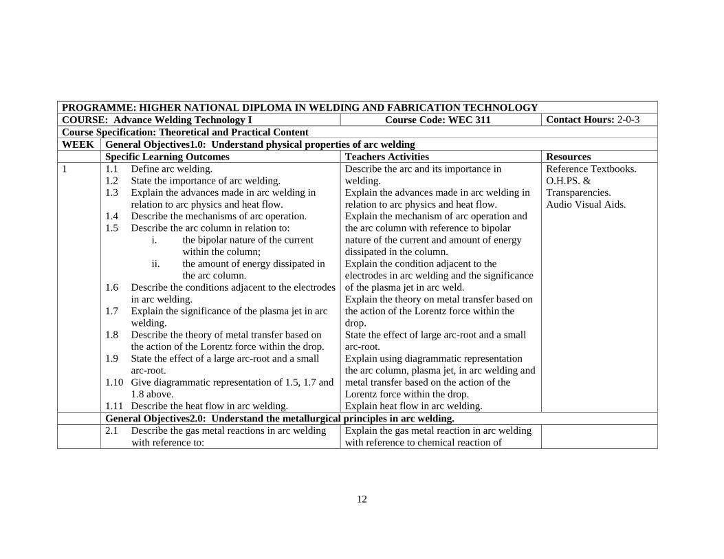
PROGRAMME: HIGHER NATIONAL DIPLOMA IN WELDING AND F ABRICATION TECHNOLOGY COURSE: Advance Welding Technology I Course Code: WEC 311 Contact Hours: 2-0-3 Course Specification: Theoretical and Practical Content WEEK General Objectives1.0: Understand physical properties of arc welding Specific Learning Outcomes Teachers Activities Resources 1 1.1 Define arc welding.
1.2 State the importance of arc welding. 1.3 Explain the advances made in arc welding in
relation to arc physics and heat flow. 1.4 Describe the mechanisms of arc operation. 1.5 Describe the arc column in relation to:
i. the bipolar nature of the current within the column;
ii. the amount of energy dissipated in the arc column.
1.6 Describe the conditions adjacent to the electrodes in arc welding.
1.7 Explain the significance of the plasma jet in arc welding.
1.8 Describe the theory of metal transfer based on the action of the Lorentz force within the drop.
1.9 State the effect of a large arc-root and a small arc-root.
1.10 Give diagrammatic representation of 1.5, 1.7 and 1.8 above.
1.11 Describe the heat flow in arc welding.
Describe the arc and its importance in welding. Explain the advances made in arc welding in relation to arc physics and heat flow. Explain the mechanism of arc operation and the arc column with reference to bipolar nature of the current and amount of energy dissipated in the column. Explain the condition adjacent to the electrodes in arc welding and the significance of the plasma jet in arc weld. Explain the theory on metal transfer based on the action of the Lorentz force within the drop. State the effect of large arc-root and a small arc-root. Explain using diagrammatic representation the arc column, plasma jet, in arc welding and metal transfer based on the action of the Lorentz force within the drop. Explain heat flow in arc welding.
Reference Textbooks. O.H.PS. & Transparencies. Audio Visual Aids.
General Objectives2.0: Understand the metallurgical principles in arc welding. 2.1 Describe the gas metal reactions in arc welding
with reference to: Explain the gas metal reaction in arc welding with reference to chemical reaction of

13
i. reaction in which gas combines chemically with the molten metal;
ii. reaction in which gas goes in to solution.
2.2 Describe the slag-metal reactions in arc welding. 2.3 Explain the following metallurgical problems in
arc welding: • cracking in the fuse zone. • cracking in the heat affected zone (HAZ)s
three forms). • unsatisfactory structures giving poor
mechanical properties and lower corrosion resistance.
2.4 Describe the following crackings which sometimes occur in the heat affected zone (HAZ):
• hot cracking; • under bead cracking in medium carbon and low
alloy steels; • reheating cracking in austenitic or creep
resisting steels. 2.5 State the causes of 2.4 above. 2.6 Investigate the variation in hardness across a
welded joint in a naturally ageing aluminium alloy.
2.7 Explain the occurrence of weld-decay in 18/8 stainless steel welded joints.
combine gas with metal, reaction in which gas goes into solution. Describe how metal react with slag in arc welding. Explain how cracking in (HAZ), in fused zone, in unsatisfactory structure given poor mechanical properties and lower corrosion resistance becomes a metallurgical problem in arc welding. Explain the following cracks sometimes found in (HAZ):
• Hot Cracking; • Reheating Cracking in austenitic or
creep resistance steels; • Unbending Cracking in medium
carbon and low alloy steels. State the causes of cracks stated above. Explain how to investigate the variation in hardness across a welded joint in a naturally ageing aluminium alloy immediately after welding and ageing. Explain the occurrence of weld-decay in 18/8 stainless steel welded joints.

14
General Objectives3.0: Understand the power supply in arc welding. 3.1 State the two types of power supplies in arc
welding (e.g. AC supply and DC generating system).
3.2 Explain with the aid of sketches the two types of power supplies in 3.1 above.
3.3 Sate the advantage of a direct current supplies over an AC supplies in arc welding.
3.4 Describe the variation of arc voltage with current for an electric arc.
3.5 Describe the “dropping characteristics” of a generator used for metallic arc welding which interacts with the arc characteristic to produce an arc operating an arc operating with equal values of current and voltage.
3.6 Explain diagrammatically the self-adjustment of arc length with a slightly sloping power source characteristics in TIG welding.
Explain using diagrammatic representation the two types power supply used in welding(AC supply and DC generating system). Explain the advantages of a DC current over an AC supplies in arc welding. Explain the dropping characteristic of a generator used for metal arc welding which interacts with characteristics to produce an arc operation with equal values of current and voltage. Using sketches, explain the variation of arc voltage with current for an electric arc. With the aid of a diagrammatic representation, explain the self adjustment of arc-length with slightly sloping power source characteristics in TIG welding.
Reference Textbooks. O.H.PS. & Transparencies. Audio Visual Aids.
General Objectives4.0: Understand arc welding practice. 1.1 Describe carbon arc welding and metallic arc
welding. 1.2 State the application of 4.1 above. 1.3 Explain the use of coated electrodes in welding. 1.4 State the function of slag produce by the
electrode coating during welding. 1.5 Describe the submerged-arc welding as a
modified continues type of metallic arc welding process.
1.6 State the applications of submerged arc welding
Explain the use of coated electrode in welding. State the functions of the principal materials used in electrode coating. Explain the application of carbon-arc welding and metallic-arc welding. State the functions of slag produced by the electrode coating during welding. Explain submerge arc welding as modified continues type of metallic welding process.
Reference Textbooks. O.H.PS. & Transparencies. Audio Visual Aids. Diagrams.
15
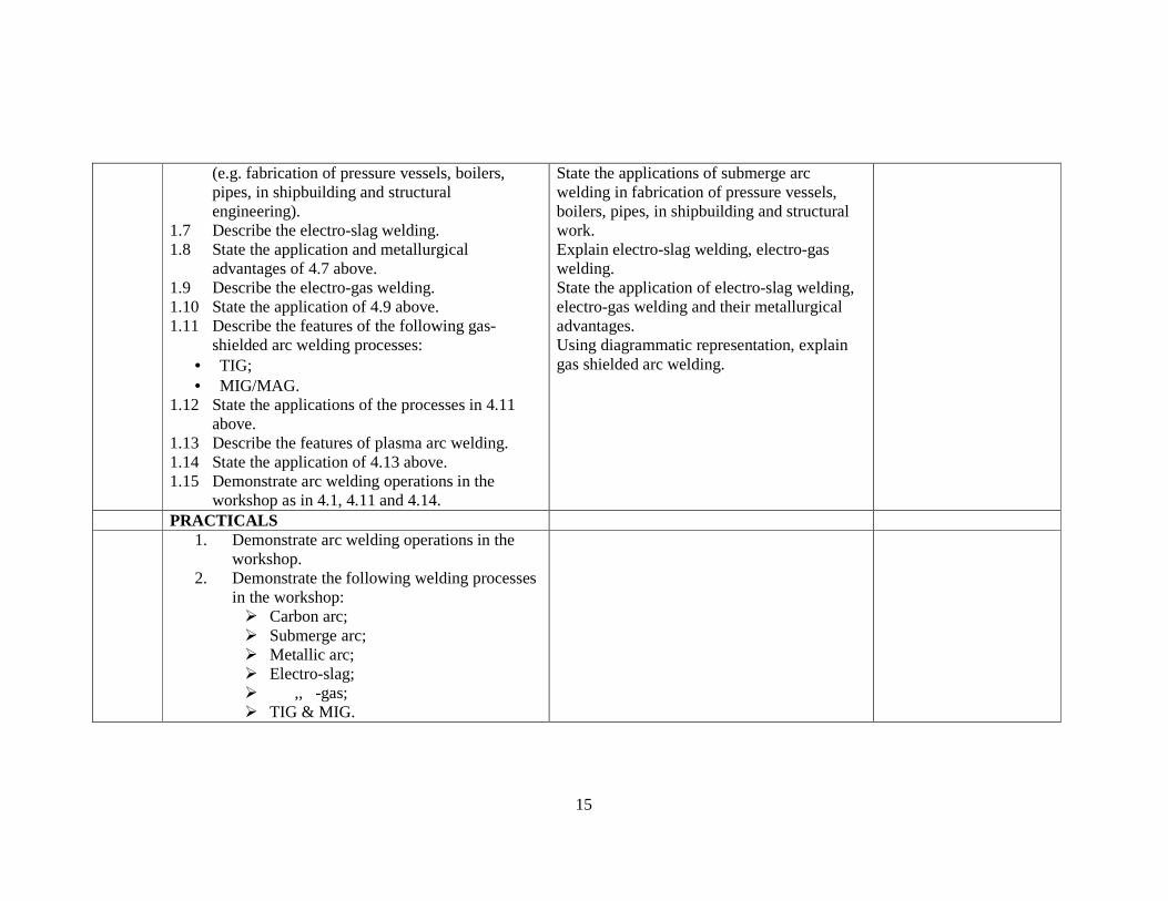
(e.g. fabrication of pressure vessels, boilers, pipes, in shipbuilding and structural engineering).
1.7 Describe the electro-slag welding. 1.8 State the application and metallurgical
advantages of 4.7 above. 1.9 Describe the electro-gas welding. 1.10 State the application of 4.9 above. 1.11 Describe the features of the following gas-
shielded arc welding processes: • TIG; • MIG/MAG.
1.12 State the applications of the processes in 4.11 above.
1.13 Describe the features of plasma arc welding. 1.14 State the application of 4.13 above. 1.15 Demonstrate arc welding operations in the
workshop as in 4.1, 4.11 and 4.14.
State the applications of submerge arc welding in fabrication of pressure vessels, boilers, pipes, in shipbuilding and structural work. Explain electro-slag welding, electro-gas welding. State the application of electro-slag welding, electro-gas welding and their metallurgical advantages. Using diagrammatic representation, explain gas shielded arc welding.
PRACTICALS 1. Demonstrate arc welding operations in the
workshop. 2. Demonstrate the following welding processes
in the workshop: � Carbon arc; � Submerge arc; � Metallic arc; � Electro-slag; � ,, -gas; � TIG & MIG.

16
PROGRAMME: HIGHER NATIONAL DIPLOMA IN WELDING AND F ABRICATION TECHNOLOGY COURSE: Advance Weld Design Course Code: WEC 312 Contact Hours: 1-0-3 Course Specification: Theoretical and Practical Content WEEK General Objectives1.0: Understand welding design features Specific Learning Outcomes Teachers Activities Resources 1 1.1 Explain the factors that affect welded joint
design. � Service Requirement; � Economic; � Equipment Availability; � Fabrication.
1.2 Explain welding position of joint accessibility.
Explain how the factors that affects the selection of a joint design for application.
General Objectives2.0: Understand welded joint designs and welds.. 2.1 Explain weld types.
2.2 Describe weld joints. 2.3 Illustrate the different joint types and edge
preparation types that can
Explain the various weld types, e.g. fillet, groove, slot, spot etc. that can be carried out. Describe the equipment required in above. Illustrate different joint types. Describe edge preparation and applications in joint types. Carry out practical edge preparation.
Welding Equipment.
General Objectives3.0: Understand the evaluation of design criteria for a given application. 3.1 Explain the relevance and evaluation of the
following design criteria: - Static Strength - Fatigue Strength - Torsion - Bending Moment - Shearing Stress - Brittle Fracture
Explain how to evaluate a design based on individual and combined factors. Explain how to use the combine effect in selecting a given joint design. Derive expressions to determine the size of required weld joint and the stress levels. Give the specifications to guide in the selection of weld sizes in 2.5 & 2.6.

17
- Corrosion Resistance. 3.2 Calculate the stress and dimensions of welded
joints. 3.3 Describe the following defects which can occur at
a welded joints; (a) slag inclusions (b) porosity (c) lack of penetration (d) lack of sidewall fusion (e) liquation cracking (f) solidification cracking (g) hydrogen cracking, etc.
3.4 Explain how defects in 2.3 above can be avoided. 3.5 Explain with diagrams the specification for
welded sizes in butt welds and fillet welds. 3.6 Explain with diagrams the dimensional
requirement for butt and fillet welded branched connections in structural, tubular and rectangular hollow sections.
3.7 Explain design conversion to weldments aimed at reducing cost or economics and quality improvements.
Explain how an existing design can be converted to a weldment and the benefits that could be derived. Carry out design exercises. Practical sizing to weld structures in 2.6.
General Objectives4.0: Understand the incidents of distortion in welding and its correction achieve by good design. 4.1 Explain the causes of distortion in welding.
4.2 Explain how amount of distortion depends upon the heat input and the degree of localisation of heat.
4.3 Describe the following modes of distortion on welded joints:
Illustrate the various joints for brazing and compare them to welded joints. Explain the expressions to determine the depth of lap, brazed area in a sarfed joint length of brazing. Compare brazing joint to welding joint by
18
- bending - shrinkage - bowing.
4.4 Explain the control of distortion through good design; e.g.
- use of double U or V joints instead of U or V.
- use of a narrow weld zone and concentrated heat source instead of slow welding spreeds and a diffuse heat source.
using similar joint for welding and brazing through joint evaluation.
General Objectives5.0: Understand the principles of non-permanent joint design. 5.1 Classify types of joints into permanent and non-
permanent. 5.2 Describe different types of rivets. 5.3 Calculate the stress and dimensions of riveted
joints. 5.4 Draw different type of threads (V-threads, square
threads, ACME threads, buttress threads, etc.). 5.5 Draw different types of bolts and nuts. 5.6 State the application of 5.5 above. 5.7 Calculate the force acting on a loaded thread
(butt, square and vee). 5.8 Determine the size of bolts subjected to tension
and shear.
Explain types of distortions that could result from welding. Explain the condition under which a joint can be classified as permanent & non-permanent joint. Describe types of rivets and bolts Explain the application of bolts and rivets. Explain how to determine the size of rivet and bolt base on type of loading and allowable stress. Draw types of threads and nuts. Describe types and uses of threads and nuts. Carry out joint design for bolting and riveting.
19
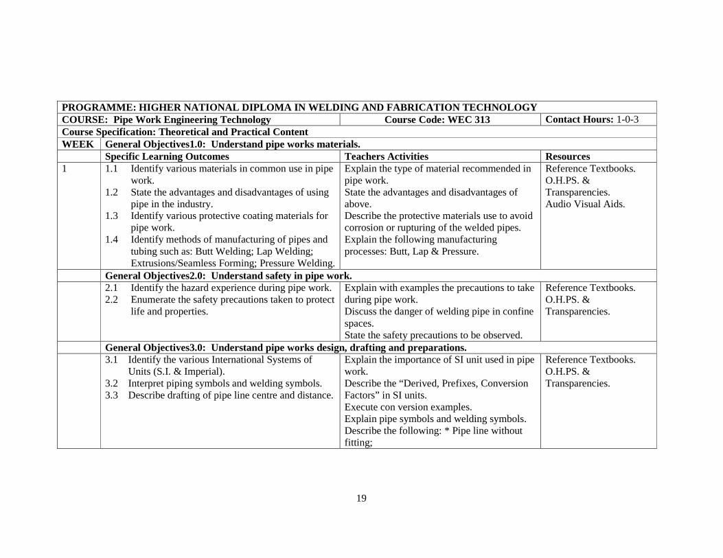
PROGRAMME: HIGHER NATIONAL DIPLOMA IN WELDING AND F ABRICATION TECHNOLOGY COURSE: Pipe Work Engineering Technology Course Code: WEC 313 Contact Hours: 1-0-3 Course Specification: Theoretical and Practical Content WEEK General Objectives1.0: Understand pipe works materials. Specific Learning Outcomes Teachers Activities Resources 1 1.1 Identify various materials in common use in pipe
work. 1.2 State the advantages and disadvantages of using
pipe in the industry. 1.3 Identify various protective coating materials for
pipe work. 1.4 Identify methods of manufacturing of pipes and
tubing such as: Butt Welding; Lap Welding; Extrusions/Seamless Forming; Pressure Welding.
Explain the type of material recommended in pipe work. State the advantages and disadvantages of above. Describe the protective materials use to avoid corrosion or rupturing of the welded pipes. Explain the following manufacturing processes: Butt, Lap & Pressure.
Reference Textbooks. O.H.PS. & Transparencies. Audio Visual Aids.
General Objectives2.0: Understand safety in pipe work. 2.1 Identify the hazard experience during pipe work.
2.2 Enumerate the safety precautions taken to protect life and properties.
Explain with examples the precautions to take during pipe work. Discuss the danger of welding pipe in confine spaces. State the safety precautions to be observed.
Reference Textbooks. O.H.PS. & Transparencies.
General Objectives3.0: Understand pipe works design, drafting and preparations. 3.1 Identify the various International Systems of
Units (S.I. & Imperial). 3.2 Interpret piping symbols and welding symbols. 3.3 Describe drafting of pipe line centre and distance.
Explain the importance of SI unit used in pipe work. Describe the “Derived, Prefixes, Conversion Factors” in SI units. Execute con version examples. Explain pipe symbols and welding symbols. Describe the following: * Pipe line without fitting;
Reference Textbooks. O.H.PS. & Transparencies.

20
• Pipe line with fittings staggered; • Pipe line without fitting not staggered.
General Objectives4.0: Understand pipe works joints and fittings design. 4.1 Identify the various pipe works standard design
data. 4.2 Describe the methods of constructing pipe
anchors, supports and caudices. 4.3 Describe types of pipe joints and design needed
during pipe works welding. 4.4 Describe piping system representation. 4.5 Explain symbols for representing all types of
valves, flanges, tees, elbows, unions etc. 4.6 Explain piping system in isometric. 4.7 Explain development techniques for interaction
of the following: • pipes with pipes; • pipes with cylinders; • pipes with conic sections.
Explain how to apply pipe works design data. Describe constructing features/jigs used in holding pipe. Explain the application of various pipe joints according to their design features. Evaluate general pipe works stress analysis for radial and longitudinal joints.
Reference Textbooks. O.H.PS. & Transparencies. Audio Visual Aids.
General Objectives5.0: Understand various pipe line welding processes. 5.1 Identify faults in pipe during works processes.
5.2 Explain welding techniques e.g. root pass etc.. 5.3 Explain marking of templates from results of 4.7
above. 5.4 Explain marking out, punching & cutting and
dressing preparatory to welding. 5.5 Describe the procedure of laying bead and
padding and padding with metal arc welding. 5.6 Describe various type of pipe work such as:
• rotational pipe welding;
Describe how faults are created and prevented during pipe works processes. Explain pipe fitting and tacking of parts, emphasizing the clearance necessary in relation to thickness of pipes. Explain the technique of manipulating the weld pool and onion hole in all positions in pipe work.
AC/DC Welding Machine. Welding Accessories.
Reference Textbooks. O.H.PS. & Transparencies. Audio Visual Aids.

21
• conventional pipe welding; • stove pipe welding.

22
PROGRAMME: HIGHER NATIONAL DIPLOMA IN WELDING AND F ABRICATION TECHNOLOGY COURSE: Advance Welding Metallurgy II Course Code: WEC 320 Contact Hours: 2-0-3 Course Specification: Theoretical & Practical Content WEEK General Objectives1.0: Understand the definition and classification of heat treatment processes. Specific Learning Outcomes Teachers Activities Resources 1 1.1 Define heat treatment.
1.2 Explain the TTT-curve application to heat treatment.
1.3 Classify heat treatment into: i. ordinary thermal treatment involving bulk
solid state changes in materials. ii. thermo-chemical treatments involving surface
changes in materials.
Define Heat treatment. Classify Heat treatment according to importance/application. Describe TTT-curve.
Reference Textbooks.
General Objectives2.0: Understand heat treatment processes involving Bulk Solid State changes in materials. 2.1 Use phase diagrams to explain solid-state changes
in materials. 2.2 Describe normalising. 2.3 State the application of 2.1 above. 2.4 Describe the following annealing processes:
i. full annealing ii. sub-critical annealing iii. isothermal annealing iv. stress relieving annealing v. homogenising annealing.
2.5 State the application of 2.4 above. 2.6 Carry out 2.2 and 2.4 in the laboratory using
welded and non welded steel samples. 2.7 Describe quenching and tempering treatment. 2.8 List quenching media.
Draw phase diagram. Use the diagram above to explain solid state changes. Describe normalizing and its application. State types of annealing. Describe quenching media and tempering. Describe the joining and quench test. Discuss ageing. Explain Mar-tempering and Aus-tempering.
Reference Textbooks. Heat treatment furnance. Hypo-Entectoid Steel Steel Forging/Casting. Tongs and other tools.

23
2.9 State the application of 2.8 above. 2.10 Carry out 2.7 with steel samples of different
carbon contents and at different quenching media. 2.11 Explain the heating and cooling rate effects on
section size and shape. 2.12 Describe the joining quench test. 2.13 Carry out water and oil quenching on carbon steel
of different sizes in the laboratory. 2.14 Explain martempering and austempering
treatments. 2.15 Carry out 2.14 above using steel samples. 2.16 Examine structure of samples metallographically. 2.17 Describe ageing treatments of aluminium alloy-
sheet (natural and artificial, the structural changes involved and application).
2.18 Perform ageing treatment on aluminium alloy sheet.
General Objectives3.0: Understand the hazards in welding engineering. 3.1 Describe the following thermo-chemical
treatments: i. Carbonitriding ii. Carburising iii. Nitriding.
3.2 Explain how treatments in 3.1 above can be carried out in liquid, gas and vacuum media.
3.3 State advantages and disadvantages of 3.2 above. 3.4 Carry out the treatments in 3.1 above in a salt-
bath furnace, using low carbon steel plates.
Define thermo-chemical treatment. Describe: a) Carburising; b) Nitriding; c) Carbonitriding. State advantages and disadvantages of the above.
Reference Textbooks Journals Samples of Steel Alloys Quenching Bath Field Trips.
24
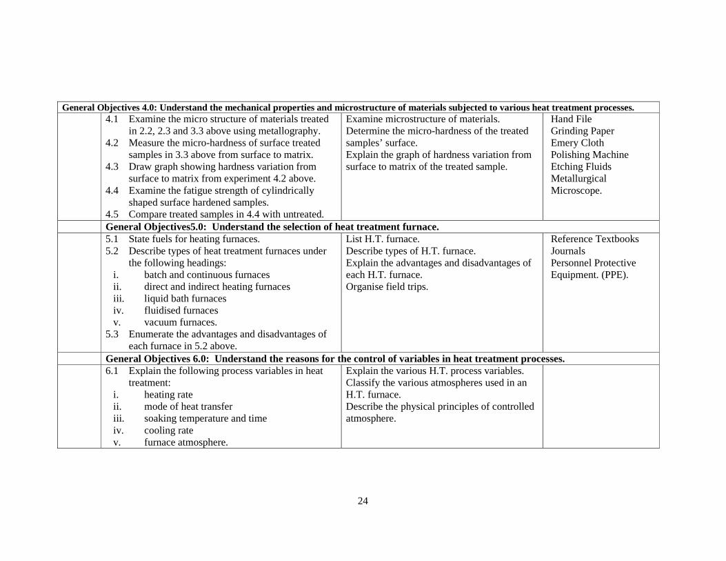
General Objectives 4.0: Understand the mechanical properties and microstructure of materials subjected to various heat treatment processes. 4.1 Examine the micro structure of materials treated
in 2.2, 2.3 and 3.3 above using metallography. 4.2 Measure the micro-hardness of surface treated
samples in 3.3 above from surface to matrix. 4.3 Draw graph showing hardness variation from
surface to matrix from experiment 4.2 above. 4.4 Examine the fatigue strength of cylindrically
shaped surface hardened samples. 4.5 Compare treated samples in 4.4 with untreated.
Examine microstructure of materials. Determine the micro-hardness of the treated samples’ surface. Explain the graph of hardness variation from surface to matrix of the treated sample.
Hand File Grinding Paper Emery Cloth Polishing Machine Etching Fluids Metallurgical Microscope.
General Objectives5.0: Understand the selection of heat treatment furnace. 5.1 State fuels for heating furnaces.
5.2 Describe types of heat treatment furnaces under the following headings:
i. batch and continuous furnaces ii. direct and indirect heating furnaces iii. liquid bath furnaces iv. fluidised furnaces v. vacuum furnaces.
5.3 Enumerate the advantages and disadvantages of each furnace in 5.2 above.
List H.T. furnace. Describe types of H.T. furnace. Explain the advantages and disadvantages of each H.T. furnace. Organise field trips.
Reference Textbooks Journals Personnel Protective Equipment. (PPE).
General Objectives 6.0: Understand the reasons for the control of variables in heat treatment processes. 6.1 Explain the following process variables in heat
treatment: i. heating rate ii. mode of heat transfer iii. soaking temperature and time iv. cooling rate v. furnace atmosphere.
Explain the various H.T. process variables. Classify the various atmospheres used in an H.T. furnace. Describe the physical principles of controlled atmosphere.

25
6.2 Classify controlled atmosphere applications into protective and chemically active.
6.3 Describe the physical principles of controlled atmosphere with respect to:
i. exidation control ii. carburisation and decarburisation control.
General Objectives 6.0: Understand the origin and control of heat treatment defects. 7.1 Explain the following defects:
i. distortion and warpage ii. cracking iii. surface sealing and/or contamination iv. grain growth v. insufficient hardness or soft spots.
7.2 Identify the defects in 7.1 above. 7.3 Describe the control procedures for the defects in
7.1 above. 7.4 Describe the formula for the calculation of pre-
heating temperature.
Discuss the Identified H.T. Defects. Explain the causes and prevention of H.T. defects.
Hammer Hacksaw Reference Textbooks. Polishing Machine Etching Fluids

26
PROGRAMME: HIGHER NATIONAL DIPLOMA IN WELDING AND F ABRICATION TECHNOLOGY COURSE: Advance Welding Technology II Course Code: WEC 321 Contact Hours: 2-0-3 Course Specification: Theoretical WEEK General Objectives1.0: Understand the various types of pressure welding. Specific Learning Outcomes Teachers Activities Resources 1 1.1 Define pressure welding.
1.2 Give brief explanation of he following welding processes:
� electrical resistance welding � oxy-acetylene pressure welding � friction welding � cold pressure welding � explosive welding � ultrasonic welding � diffusion welding.
Explain pressure welding with reference to the following types of pressure welding operations:
� Electrical Resistance Welding; � Oxy-acetylene Welding; � Friction Welding etc..
General Objectives2.0: Understand the principle and practice of electrical resistance welding. 2.1 Classify electrical resistance welding processes as
spot, scam, butt and flash welding operations. 2.2 Describe each types of operations in 2.1 above. 2.3 Explain how each of the following process
variables affect the: � weld quality of spot, scam and projection
processes; � type of material to be welded; � welding current; � weld time; � solidification time; � electrical force; � diameter of the tip of the electrode relative to the
Explain the classification of electrical resistance welding. Explain how different variables affect the quality of weld produced from resistance welding. Using derivation, explain the expression for welding temperature. Explain the two types of thermal treatment in resistance welding.

27
thickness of metal between the electrodes – (2.5 DT)mm where T = total metal thickness;
� post-heat treatment. 2.4 Explain with diagram weld defects which occur
in spot and scam processes. 2.5 State how the above can be avoided. 2.6 State various methods that could be used to
inspect and test weld made with spot, projection and scam processes.
2.7 Demonstrate spot, scam and projection welding practice in the workshop using suitable metal thickness and electrodes tip diameter.
2.8 Perform inspection and testing of weld quality from sample in 2.7 above using methods in 2.6 above.
2.9 Explain the expression H=KI2Rt which is the heat developed in the region of a spot weld, where K is a factor which takes account of heat losses.
2.10 Explain sources of heat loss in spot welding, which K takes account of.
2.11 Explain how total resistance between the electrodes is three separate resistance viz:
(b) the specific resistance of the parts being jointed.
(c) the resistance of the metal interface between the parts jointed.
(d) the resistance at the points of contact between the electrodes and the metal parts.

28
2.12 Explain how 2.11 (a) and (b) above would be affected by the following variables:
- The pressure applied by the electrodes.
- The shape and size and surface condition of the electrodes.
- The surface condition of the parts being jointed (extent of surface oxidation).
2.13 Derive the expression for welding temperature T using 2.9 above and
H = {π d2/2 . 2L . S . C . (T - To)}, the quantity of heat necessary to raise the cylinder of metal diameter d, and height 2L, held between the ends of the electrodes to the welding temperature (T) where: S = relative density of the metal being welded (kg/m3). C = its specific heat (J/kgoC). To = temperature of surrounding atmosphere (oC). 2.14 Describe the various machines available for spot,
seam and projection welding. 2.15 Describe the resistance Butt welding and flash
welding processes. 2.16 Explain the defect “flat – spots” inherent in flash
welds. 2.17 State the application of flash welding (e.g. joining
together the ends of sheets, wires and tubes). 2.18 Carryout the operations in 2.15 above in the

29
workshop. 2.19 Give diagrammatic explanation of the following
during resistance welding: (ii) the overall variation of
resistance between the welding electrodes with welding time.
(iii) variation of interface resistance with electrodes pressure.
2.20 Describe with diagram the two types of thermal treatment used in resistance welding to control the structure of HAZ (e.g. prevention of hardening and tempering the hardened core.).
2.21 Demonstrate the operations in 2.19 above on resistance welded samples.
General Objectives3.0: Understand the production of seam welding tubes. 3.1 State the uses of seam welded tubes and pipes
(e.g. as conduit for electrical cables and for carrying water and gas at low pressure, furniture frames, boiler tubes, etc.).
3.2 Describe with diagrams: (a) the butt welded process
of tube making. (b) the lap weld process of
tube making. (c) the continuous – butt
weld process. (d) the electrical resistance
Explain the uses of seam welding in tubes, pipes etc.. Using sketches, explain butt weld process.

30
weld process of tube making.
General Objectives4.0: Understand the principles and practice of other pressure welding processes. 4.1 Describe the following pressure welding
processes: (i) Friction welding (ii) Cold pressure welding (iii) Explosive welding (iv) Ultrasonic welding (v) Diffusion welding.
4.2 Explain how the following parameters affect pressure welding processes in 4.1 above:
- surface preparation - temperature - oxide solubility - crystal structure - pressure.
4.3 State the application of the processes in 4.2 above.
4.4 State the main requirement of the material being cold welded (i.e. high ductility to withstand heavy reduction necessitated by the process).
4.5 Explain the need for the treatment of the joint after cold welding.
Explain pressure welding processes. Describe how various parameters affect pressure welding. Explain material need for cold welding. Explain the need for the treatment of joint after cold welding.
Model of Pressure welding Machine. Model of Cold Welding Machine.
PRACTICALS 1. Demonstrate spot, seam and projection welding
in the workshop using suitable metal thickness and electrode tip diameter.
31
2. Demonstrate the inspection and testing of weld quality produced from the process above.
3. Demonstrate resistance Butt & Flash welding process in the workshop.
4. Demonstrate thermal treatment on welded sample of resistance welding process.

32
PROGRAMME: HIGHER NATIONAL DIPLOMA IN WELDING AND F ABRICATION TECHNOLOGY COURSE: Corrosion Technology Course Code: WEC 322 Contact Hours: 2-0-0 Course Specification: Theoretical WEEK General Objectives1.0: Know the importance of corrosion. Specific Learning Outcomes Teachers Activities Resources 1 1.1 Define corrosion.
1.2 Explain corrosion damage on materials. 1.3 Explain some beneficial cases of corrosion, e.g.; � Batteries � Electro-chemical machining.
Explain corrosion and its consequences on materials, environment and overall economy. Discuss beneficial cases of corrosion.
General Objectives2.0: Understand the principle of corrosion. 2.1 Explain corrosion as an electro-chemical process
with particular reference to anoidic and cathodic site reactions.
2.2 Explain the environmental effects of corrosion. 2.3 Derive Nernst’s equation. 2.4 State Tafel equation. 2.5 Explain pour – Baix diagram and its relevance. 2.6 Describe Evans diagram. 2.7 Explain the metallurgical effects of corrosion.
Explain electrochemical nature of corrosion (equilibra & kinetics). Discuss the derivation of Neernst equation from first principles. Explain the use of Pambaix diagrams in corrosion studies. Give illustrations. State Tatel’s equations. Explain how the above is applied in cathodic protection by impresso current. Explain the application of Erams diagrams in corrosion studies. Give exercises.
General Objectives3.0: Know the common types of corrosion. 3.1 Describe the occurrence and features of the
following forms of corrosion: � uniform attack � galvanic corrosion
Explain the different types of corrosion. Give examples of occurrences of above. Explain the standard expression for corrosion rate and how it relates to each type.

33
� crevice corrosion � pitting corrosion � intergranular corrosion � selective leaching � erosion corrosion � stress corrosion cracking � hydrogen damage � corrosion fatigue
Give practical situation and predict likely types of corrosion rate and how it relates to each type. Give practical situation and predict likely types of corrosion. Give exercise.
General Objectives4.0: Know corrosion testing methods. 4.1 Classify corrosion testing methods and
equipments. 4.2 State the limitations of 4.1 above. 4.3 Describe major testing methods. 4.4 Explain the standard expressions for corrosion
rate.
Discuss corrosion monitoring techniques and equipment used. Explain the limitation of each technique.
General Objectives5.0: Know corrosion control and prevention. 5.1 Explain the principles underlying corrosion
control and prevention. 5.2 Describe corrosion controls and prevention
techniques under the following: � material selection � design � alteration of the environment � cathodic and anodic protection � coatings.
Explain corrosion control prevention methods, highlighting underlying principles and their applications.
General Objectives4.0: Understand the . 6.1 Enumerate the corrosion rates of various sections
of steel weldment. 6.2 Give account of corrosion in the following
Analyse corrosion occurrence in weldments, petroleum facilities i.e. down hole, topside, pipe line structures and hydrocarbon plant.

34
petroleum operating regions: � down hole � topside facilities � pipelines � structures � hydrocarbon plant. 6.3 Given account of corrosion in the steel,
transportation and non-oil & chemical industries.
And also transportation and non oil chemical industries.
35
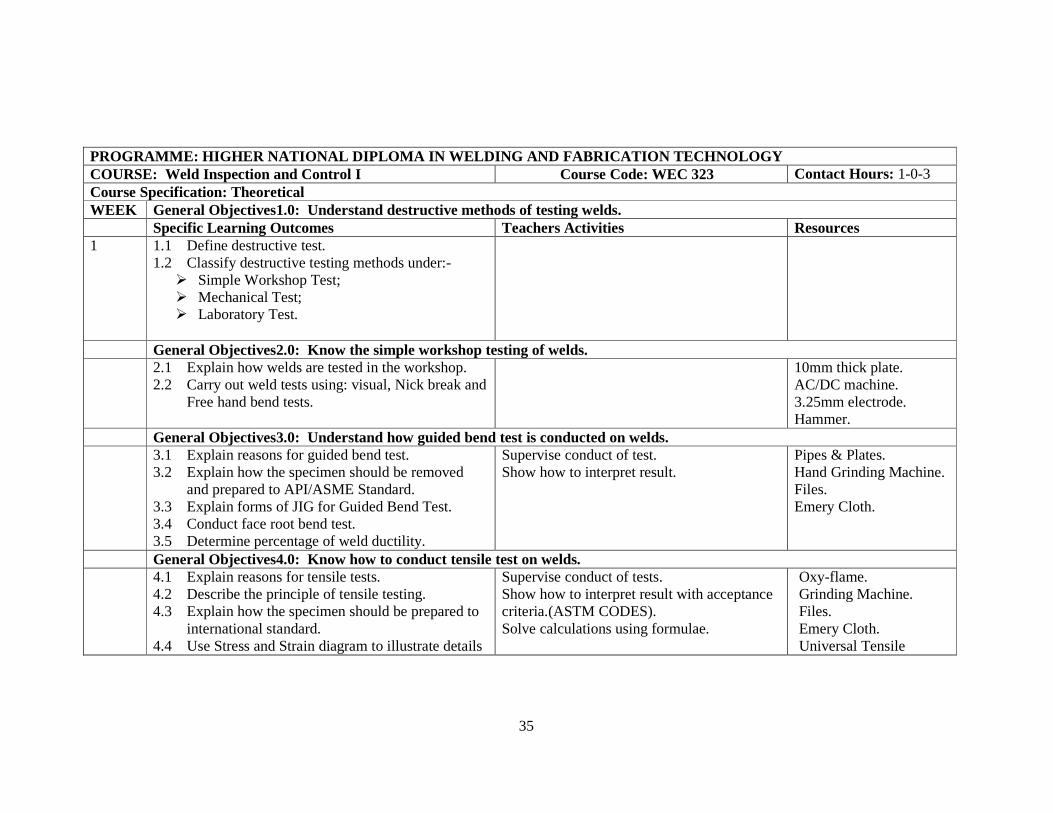
PROGRAMME: HIGHER NATIONAL DIPLOMA IN WELDING AND F ABRICATION TECHNOLOGY COURSE: Weld Inspection and Control I Course Code: WEC 323 Contact Hours: 1-0-3 Course Specification: Theoretical WEEK General Objectives1.0: Understand destructive methods of testing welds. Specific Learning Outcomes Teachers Activities Resources 1 1.1 Define destructive test.
1.2 Classify destructive testing methods under:- � Simple Workshop Test; � Mechanical Test; � Laboratory Test.
General Objectives2.0: Know the simple workshop testing of welds. 2.1 Explain how welds are tested in the workshop.
2.2 Carry out weld tests using: visual, Nick break and Free hand bend tests.
10mm thick plate. AC/DC machine. 3.25mm electrode. Hammer.
General Objectives3.0: Understand how guided bend test is conducted on welds. 3.1 Explain reasons for guided bend test.
3.2 Explain how the specimen should be removed and prepared to API/ASME Standard.
3.3 Explain forms of JIG for Guided Bend Test. 3.4 Conduct face root bend test. 3.5 Determine percentage of weld ductility.
Supervise conduct of test. Show how to interpret result.
Pipes & Plates. Hand Grinding Machine. Files. Emery Cloth.
General Objectives4.0: Know how to conduct tensile test on welds. 4.1 Explain reasons for tensile tests.
4.2 Describe the principle of tensile testing. 4.3 Explain how the specimen should be prepared to
international standard. 4.4 Use Stress and Strain diagram to illustrate details
Supervise conduct of tests. Show how to interpret result with acceptance criteria.(ASTM CODES). Solve calculations using formulae.
Oxy-flame. Grinding Machine. Files. Emery Cloth. Universal Tensile
36
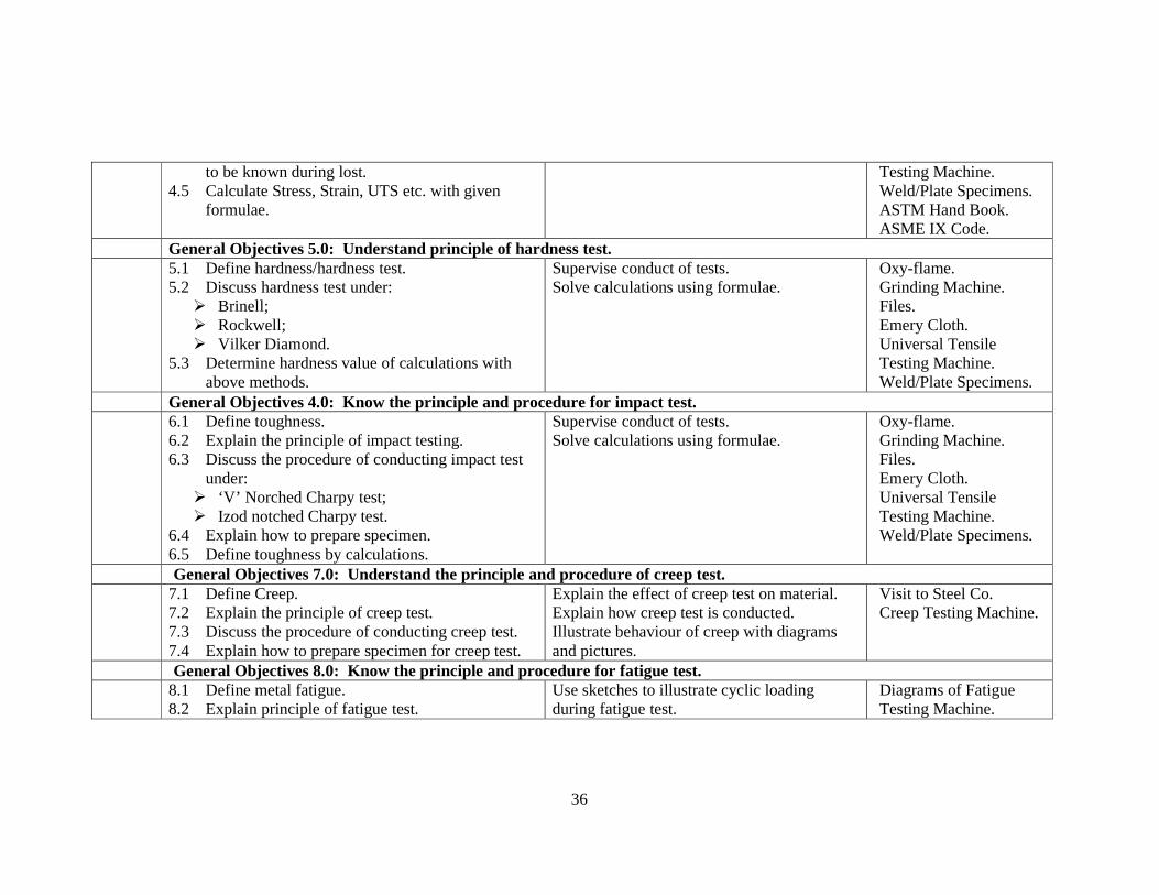
to be known during lost. 4.5 Calculate Stress, Strain, UTS etc. with given
formulae.
Testing Machine. Weld/Plate Specimens. ASTM Hand Book. ASME IX Code.
General Objectives 5.0: Understand principle of hardness test. 5.1 Define hardness/hardness test.
5.2 Discuss hardness test under: � Brinell; � Rockwell; � Vilker Diamond.
5.3 Determine hardness value of calculations with above methods.
Supervise conduct of tests. Solve calculations using formulae.
Oxy-flame. Grinding Machine. Files. Emery Cloth. Universal Tensile Testing Machine. Weld/Plate Specimens.
General Objectives 4.0: Know the principle and procedure for impact test. 6.1 Define toughness.
6.2 Explain the principle of impact testing. 6.3 Discuss the procedure of conducting impact test
under: � ‘V’ Norched Charpy test; � Izod notched Charpy test.
6.4 Explain how to prepare specimen. 6.5 Define toughness by calculations.
Supervise conduct of tests. Solve calculations using formulae.
Oxy-flame. Grinding Machine. Files. Emery Cloth. Universal Tensile Testing Machine. Weld/Plate Specimens.
General Objectives 7.0: Understand the principle and procedure of creep test. 7.1 Define Creep.
7.2 Explain the principle of creep test. 7.3 Discuss the procedure of conducting creep test. 7.4 Explain how to prepare specimen for creep test.
Explain the effect of creep test on material. Explain how creep test is conducted. Illustrate behaviour of creep with diagrams and pictures.
Visit to Steel Co. Creep Testing Machine.
General Objectives 8.0: Know the principle and procedure for fatigue test. 8.1 Define metal fatigue.
8.2 Explain principle of fatigue test. Use sketches to illustrate cyclic loading during fatigue test.
Diagrams of Fatigue Testing Machine.

37
8.3 Discuss the procedure of conducting fatigue test. 8.4 Discuss factors that affect fatigue limit.
Sketch fatigue curve. Show fatigue limit on the curve. Sketch structure of fatigue failure.
AWS Hand Book.
General Objectives 9.0: Understand metallographic testing of welds. 9.1 Define metallography.
9.2 Explain how to use metallographic testing to determine soundness of welds.
9.3 Describe macro-graphic testing procedure. 9.4 Prepare specimen for macro-test. 9.5 Prepare chemicals suitable for metallographic
inspection. 9.6 Conduct interpretation of macro-examination
result. 9.7 Describe the procedure for micro-examination. 9.8 Describe the operation of metallurgical
microscope in testing welds. 9.9 Conduct interpretation of micro-examination
result of 9.8 above.
Explain micro-examination procedures. Illustrate with sketches how macro-specimen are prepared. Supervise students during preparation of etching reagent. Conduct micro-examination. Allow students to interpret result of test above. Demonstrate micro-testing procedures in the laboratory. Supervise students during specimen preparation. Supervise students during micro investigation
Polishing Machine. Metallurgical Microscope.
General Objectives 10.0: Understand chemical testing of welds. 10.1 Explain chemical testing of metal.
10.2 Describe how it is used to determine: � Composition of weld metal; � Corrosion resistance of weld metal.
Explain chemical analytical test under: � Quantitative analysis; � Qualitative analysis.
Ask students to find out other suitable chemicals for use in conducting chemical test.
AWS Hand Book. ASTM Hand Book.

38
PROGRAMME: HIGHER NATIONAL DIPLOMA IN WELDING AND F ABRICATION TECHNOLOGY COURSE: Equipment Maintenance Management Course Code: WEC 410 Contact Hours: 2-0-0 Course Specification: Theoretical WEEK General Objectives1.0: Know the meaning, importance types and characteristics of maintenance system. Specific Learning Outcomes Teachers Activities Resources 1 1.1 Define the following:
� Maintenance; � Management. 1.2 Relate the above definitions to welding
equipment. 1.3 Explain management functions e.g. Planning,
Organising, Staffing, Directing, Controlling, Coordinating and Motivating.
1.4 Describe maintenance strategies e.g. Preventive, Planned Breakdown, Shutdown, Running and Contract.
1.5 Explain the characteristics of each type of maintenance system.
1.6 State the functions of each of the maintenance system.
1.7 Describe the precautions and planning techniques for shutdown maintenance.
1.8 State the advantages or benefits derived from a successful maintenance system.
1.9 Explain the importance of maintenance in industries.
Describe maintenance management, planning, organizing, and staffing e.t.c. as management functions. Explain in detail the following maintenance strategies and characteristics:- preventative, planned, breakdown and shutdown e.t.c.. Describe in detail the functions of each of the maintenance system above. Describe the precautionary measures when planning for shutdown maintenance to avoid total breakdown of the organisational system. Explain in detail the advantages and benefits derived from a successful maintenance system. Explain the importance of maintenance in industries.
Reference Textbooks O.H.P. & Transparencies.
General Objectives2.0: Understand the organisation of a maintenance department. 2.1 Define maintenance organisation.
2.2 Identify maintenance services required within a Explain in detail 2.1 – 2.3. Explain the high, middle and low level
Complete Engineering Tool Box.

39
given enterprise. 2.3 List the basic organisational guidelines for
carrying out maintenance functions. 2.4 Describe the main levels of management that
exists within functions of the maintenance organisation.
management that exist within the functions of the maintenance organisation. Guide the student to replace the faulty parts of the machines.
New Functional Parts for Replacement. O.H.P. & Transparencies.
General Objectives3.0: Understand preventive maintenance techniques. 3.1 Describe the components of planned maintenance
system. 3.2 Explain the problems involved in planning for
preventive maintenance. 3.3 State advantages of preventive maintenance. 3.4 Describe the method of establishing preventive
maintenance in an industry. 3.5 Explain the methods of avoiding problems
resulting from improper operating procedures of welding and associated machines and equipment in the fabrication workshop.
3.6 Explain the advantages of routine inspection. 3.7 Describe different levels, of equipment
monitoring. 3.8 Identify the relevant equipment records for
maintenance purposes. 3.9 Analyse equipment records available in a welding
and fabrication shop.
Describe the components of planned maintenance system. Explain the problems encountered in planning for preventive maintenance. Explain the advantages of preventive maintenance.
Reference Textbooks O.H.P. & Transparencies. Available Equipment Records.
General Objectives4.0: Know the maintenance control procedures. 4.1 Define maintenance control.
4.2 Explain sources of control data and their inter-relationship.
Describe source of control data and their inter-relationship. Describe the procedure for maintenance
Reference Textbooks O.H.P. & Transparencies.

40
4.3 State the procedures for maintenance budgeting. 4.4 Define operational controls. 4.5 List performance ratios. 4.6 Explain Tero technology. 4.7 Apply 4.6 to welding equipment. 4.8 Describe stock control techniques and spare parts
management.
budgeting. Explain in detail 4.6 – 4.8.
General Objectives5.0: Understand maintenance report presentation. 5.1 Explain the purpose of reporting.
5.2 State guidelines for reporting to management. 5.3 Develop a format for reporting and evaluating
maintenance work. 5.4 Apply 5.3 above to maintenance of specific
equipment/machines in a welding and fabrication shop.
Explain the purpose and guideline for reporting to management. Elaborate on 5.2 – 5.4.
Reference Textbooks O.H.P. & Transparencies.
PRACTICALS. 1. Identify the non functioning welding machines
and gas welding equipments in the workshop. 2. Ascertain their faulty parts. 3. Teacher should guide the students to effect the
replacement of the faulty part in 2. above. 4. Update equipment records in the welding shop. 5. Students should be guided in updating spare
parts records in the shop. 6. Students should develop equipment machines
report forms.
Guide in the execution of item 1 – 6.

41
PROGRAMME: HIGHER NATIONAL DIPLOMA IN WELDING AND F ABRICATION TECHNOLOGY COURSE: Advance Fabrication Technology Course Code: WEC 411 Contact Hours: 2-0-3 Course Specification: Theoretical WEEK General Objectives1.0: Understand classification of metal working processes. Specific Learning Outcomes Teachers Activities Resources 1 1.1 Define metal working.
1.2 Classify metal working into primary & secondary processes.
1.3 Relate metal working to elastic & plastic deformation.
1.4 Explain the effect of temperature on metal working processes.
1.5 Distinguish between hot and cold working.
Explain the classification of metal working into primary & secondary processes. Explain with aid of diagrams where necessary 1.3 –1.5. Conduct experiments on cold & hot working of metals.
General Objectives2.0: Understand rolling of metals. 2.1 Identify rolled products by their correct
terminology. 2.2 Classify rolling mills according to products. 2.3 Classify rolling processes. 2.4 Describe the continuous process for producing
billets, bars, plates & metal sheets. 2.5 State possible rolling defects on bars. 2.6 Explain how to identify 2.5 above. 2.7 Enumerate control measures for the defects in 2.5
above. 2.8 State steel grades that can be rolled to produce the
following: � ribbed bars. � plain bars. � wire coils.
Describe rolled products by their correct terminology. Identify possible defects on bars. Describe steel grades that can be rolled to produce the following:
- ribbed bars - wire coils - plain bars.
Demonstrate fabrication of items using the products in 2.7 above. Give exercises.

42
2.9 State uses of the products in 2.8 above in fabrication works.
2.10 Demonstrate fabrication of items using the products in 2.8 above.
2.11 Demonstrate appropriate joining techniques of 2.10 above.
General Objectives3.0: Understand cold working. 3.1 Classify sheet metal forming processes.
3.2 Describe the following sheet metal operations: � shearing � bending � stretching � deep drawing, etc.
3.3 Explain the factors effecting deep draw-ability and stretch-ability of sheet metals.
3.4 State deep-drawing defects and causes. 3.5 Demonstrate the operations in 3.2 above, using
mild steel and aluminium alloy sheet to produce suitable items.
3.6 Explain stiffening in fabrication of metal sheet and plates.
3.7 Describe the following methods of stiffening sheet metal:
� wired edge � folded edge � swaging etc.
3.8 Describe the following methods of stiffening plates and structural members:
� web stiffening
Describe sheet metal forming processes. Explain with sketches where necessary 3.2. Identify drawing defects. State the causes of above. Carry out operations in 3.2 using mild steel & aluminium alloy sheet to produce suitable items. Carry out operations of stiffening sheet, plates & structural members using the various methods in 3.7 & 3.8. Give exercises.

43
� troughing � channelling � ribbing.
3.9 Demonstrate stiffening operations on sheet metal and plates.
44
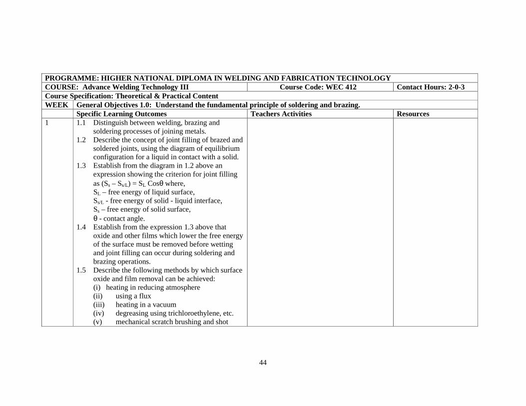
PROGRAMME: HIGHER NATIONAL DIPLOMA IN WELDING AND F ABRICATION TECHNOLOGY COURSE: Advance Welding Technology III Course Code: WEC 412 Contact Hours: 2-0-3 Course Specification: Theoretical & Practical Content WEEK General Objectives 1.0: Understand the fundamental principle of soldering and brazing. Specific Learning Outcomes Teachers Activities Resources 1 1.1 Distinguish between welding, brazing and
soldering processes of joining metals. 1.2 Describe the concept of joint filling of brazed and
soldered joints, using the diagram of equilibrium configuration for a liquid in contact with a solid.
1.3 Establish from the diagram in 1.2 above an expression showing the criterion for joint filling as (Ss – Ss/L) = SL Cosθ where,
SL – free energy of liquid surface, Ss/L - free energy of solid - liquid interface, Ss – free energy of solid surface, θ - contact angle. 1.4 Establish from the expression 1.3 above that
oxide and other films which lower the free energy of the surface must be removed before wetting and joint filling can occur during soldering and brazing operations.
1.5 Describe the following methods by which surface oxide and film removal can be achieved:
(i) heating in reducing atmosphere (ii) using a flux (iii) heating in a vacuum (iv) degreasing using trichloroethylene, etc. (v) mechanical scratch brushing and shot

45
blasting. 1.6 Demonstrate surface cleaning of metals to be
soldered and brazed using methods in 1.5 above. 1.7 Describe the metallurgical principles of brazed
joints in terms of: (i) flow of filler material (ii) joints strength.
General Objectives 2.0: Understand the types of fluxes and their roles in soldering and brazing. 2.1 Describe with diagram the action of a suitable
flux during soldering operation. 2.2 State the properties which a soldering flux should
possess. 2.3 Describe the following soldering fluxes:
(a) solutions containing inorganic substances, (e.g. zinc chloride, ammonium chloride and hydrochloric acid).
(b) fluxes based on resin. 2.4 State the advantages of (a) and (b) above. 2.5 State the brazing fluxes for brazing at high and
low temperatures.
General Objectives 3.0: Understand soldering and brazing practice. 3.1 Using a graph, describe the Lead - Tin thermal
equilibrium. 3.2 Identify in the diagram 3.1 above the regions
representing the following solders: (i) Plumber’s solder (ii) Coarse Tinman’s solder (iii) Tinman’s solder.
46
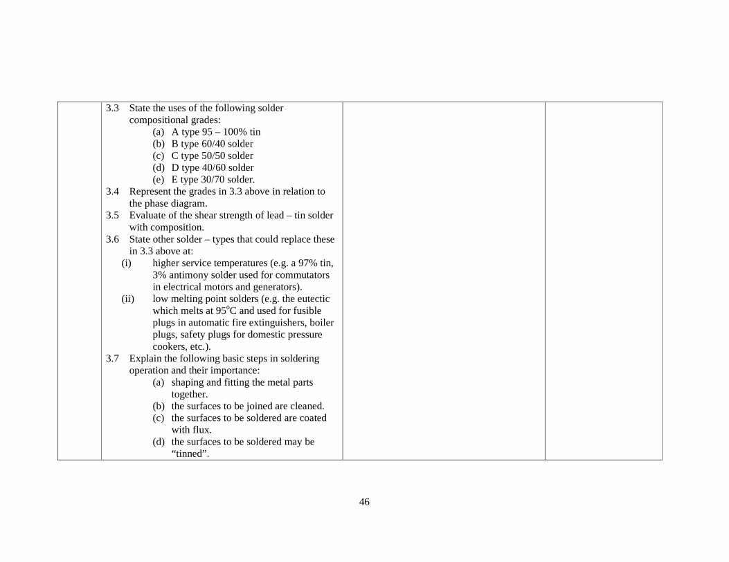
3.3 State the uses of the following solder compositional grades:
(a) A type 95 – 100% tin (b) B type 60/40 solder (c) C type 50/50 solder (d) D type 40/60 solder (e) E type 30/70 solder.
3.4 Represent the grades in 3.3 above in relation to the phase diagram.
3.5 Evaluate of the shear strength of lead – tin solder with composition.
3.6 State other solder – types that could replace these in 3.3 above at:
(i) higher service temperatures (e.g. a 97% tin, 3% antimony solder used for commutators in electrical motors and generators).
(ii) low melting point solders (e.g. the eutectic which melts at 95oC and used for fusible plugs in automatic fire extinguishers, boiler plugs, safety plugs for domestic pressure cookers, etc.).
3.7 Explain the following basic steps in soldering operation and their importance:
(a) shaping and fitting the metal parts together.
(b) the surfaces to be joined are cleaned. (c) the surfaces to be soldered are coated
with flux. (d) the surfaces to be soldered may be
“tinned”.

47
(e) surplus solder is removed and the joint allowed to cool.
3.8 Produce tin – cans and other articles by soldering using the steps in 3.7 above.
3.9 State the advantages of brazing over soldering. 3.10 State the properties which brazing filler metals
should possess. 3.11 Give the compositions of the following brazing
filler metals: (i) Brazing brasses. (ii) Phosphorus – bearing brazing alloys. (iii) Silver solders. (iv) Aluminium brazing.
3.12 State the applications of i - iv in 3.11 above. 3.13 Describe the following brazing processes:
(a) Torch brazing (b) Furnace brazing in an air atmosphere (c) Furnace brazing in vacuum (d) Dip brazing in a salt bath (e) Induction brazing (f) Resistance brazing.
3.14 State the application of a - f in 3.13 above. 3.15 Demonstrate brazing operations in the workshop
using methods in 3.13 above and suitable filler metal and flux.
General Objectives 4.0: Understand the application of special welding processes. 4.1 Describe the following special processes:
(i) GTAW (TIG). (ii) GMAW (MIG).

48
(iii) Submerge Arc (iv) Resistance Welding (Spot, Flash-bar). (v) Plasma Arc. (vi) Flux Core.
4.2 State advantages of each process above. 4.3 Demonstrate operations in the workshop using
methods in 4.1.

49
PROGRAMME: HIGHER NATIONAL DIPLOMA IN WELDING AND FABRICATION TECHNOLOGY COURSE: Weld Inspection & Control II Course Code: WEC 413 Contact Hours: l2, P3 Course Specification: Theoretical & Practical WEEK General Objectives1.0: Understand General principles of Non-destructive Testing & practice in Industry. Specific Learning Outcomes Teachers Activities Resources 1 1.1 Define non-destructive Testing
1.2 Enumerate advantages & disadvantages of NDT over destructive methods
1.3 Understand classification of NDT Personnel 1.4 Know NDT Professional bodies’ certification
requirements.
Explain and confirm student understanding of importance of NDT methods in Quality control.
_
General Objectives2.0: Understand and perform visual inspection of welds 2.1 Explain the principles of Visual Inspection.
2.2 Describe how to use the visual inspection kit 2.3 Determine defects via visual inspection 2.4 Explain limitations of visual inspection 2.5 Carry out visual inspection of welded plates.
Explain and confirm students ability to carry out visual inspection.
Visual inspection Kit.
General Objectives3.0: Understand liquid penetrant Testing Method 3.1 Explain the principles of liquid (dye)
penetrant testing method. 3.2 Explain how to carry out a liquid penetrant
inspection on weld samples. 3.3 Explain the use of visible dye and florescence
dye in liquid penetrant method 3.4 Explain the limitations of the method. 3.5 Carry out liquid penetrant test with visible
dye & florescence dye.
Explain and confirm student’s ability to carry out liquid penetrant test.
2. Visible dye treatment test Kit
3. florescence dye penetrant test Kit.
General Objectives4.0: Understand Magnetic Particle method. 4.1 Explain the principles of magnetic particle Explain and confirm students ability to carry 1. Permanent

50
method. 4.2 Explain the procedure for magnetic particle
inspection method. 4.3 Explain the limitations of the method. 4.4 Carry out magnetic particle test on weld
samples.
out magnetic particles testing. magnet 2. electro magnet 3. solenoid 4. head shot 5. prodes 6. standard
specimen General Objectives5.0: Understand Ultrasonic testing method. 5.1 Explain the principles of Ultrasonic testing
method. 5.2 Explain how to carry out for Ultrasonic testing
materials. 5.3 Carry out ultrasonic testing for thickness
measurement and weld inspection.
Explain ands confirm student ability to carry out and interpret results of Ultrasonic testing.
2. D-Meters 3. UT Flow
detectors 4. calibration blocks 5. standard
specimen General Objectives6.0: Understand Radiographic Testing Method 6.1 Explain the principles of Radiographic
testing method 6.2 Explain how to carry out the procedure for
radiographic testing. 6.3 Know safety precautions in industrial
radiography 6.4 Carry out radiographic testing of welds
Explain and confirm students ability to carry out and interpret results of radiographic testing.
2. Gamma ray radiographic projector.
3. x-ray industrial radiographic machines
4. dark room facility and accessories.
5. Exposure bunker.
51
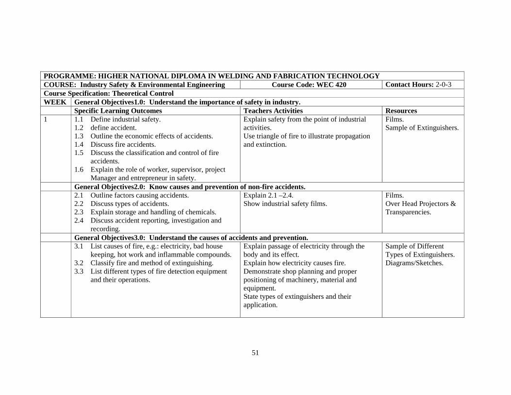
PROGRAMME: HIGHER NATIONAL DIPLOMA IN WELDING AND F ABRICATION TECHNOLOGY COURSE: Industry Safety & Environmental Engineering Course Code: WEC 420 Contact Hours: 2-0-3 Course Specification: Theoretical Control WEEK General Objectives1.0: Understand the importance of safety in industry. Specific Learning Outcomes Teachers Activities Resources 1 1.1 Define industrial safety.
1.2 define accident. 1.3 Outline the economic effects of accidents. 1.4 Discuss fire accidents. 1.5 Discuss the classification and control of fire
accidents. 1.6 Explain the role of worker, supervisor, project
Manager and entrepreneur in safety.
Explain safety from the point of industrial activities. Use triangle of fire to illustrate propagation and extinction.
Films. Sample of Extinguishers.
General Objectives2.0: Know causes and prevention of non-fire accidents. 2.1 Outline factors causing accidents.
2.2 Discuss types of accidents. 2.3 Explain storage and handling of chemicals. 2.4 Discuss accident reporting, investigation and
recording.
Explain 2.1 –2.4. Show industrial safety films.
Films. Over Head Projectors & Transparencies.
General Objectives3.0: Understand the causes of accidents and prevention. 3.1 List causes of fire, e.g.: electricity, bad house
keeping, hot work and inflammable compounds. 3.2 Classify fire and method of extinguishing. 3.3 List different types of fire detection equipment
and their operations.
Explain passage of electricity through the body and its effect. Explain how electricity causes fire. Demonstrate shop planning and proper positioning of machinery, material and equipment. State types of extinguishers and their application.
Sample of Different Types of Extinguishers. Diagrams/Sketches.

52
General Objectives4.0: Understand the factory acts and laws. 4.1 Define factory as given by the factory act.
4.2 Explain the role of factory act in industrial activity.
4.3 Give a general view of the Factory Act as it affects:
� use and maintenance of machinery. � factory buildings. � HSE management policy of any company.
Explain origin of Factory Acts. Examine the contents and implementation of Factory Acts. Discuss handling, care, storage and use of tools and machinery. Examine HSE management policy as it affects industrial outfits.
Slide Projector. O.H.P. & Transparencies. Posters/Sketches.
General Objectives5.0: Understand environmental pollution and its effects. 5.1 Define environmental pollution.
5.2 List pollutants. 5.3 State the effects of 5.2 on man, plants and
animals. 5.4 Classify pollution into air, land and sea
pollutions. 5.5 Explain types of hazardous wastes: radioactive,
chemical, biological and flammable.
Examine the environment as the surroundings, including the vegetation, man, animal, air, water and soil. List pollutants and the activities of man in pollution. List nature, industry, homes and traffics as sources of pollution.
O.H.P. & Transparencies. Diagrams/Sketches
General Objectives 6.0: Know the generation and management of solid wastes. 6.1 Define solid waste.
6.2 Explain sources of solid wastes: � Animal � Agricultural � Commercial � Municipal � Industrial.
6.3 Discuss constituents of solid waste: garbage, rubbish, trash, ashes, carcass,
Explain each of the sample of solid waste. Examine the composition of solid waste. Explain the existing practices in solid waste management. Organise site visitations.
O.H.P. & Transparencies.

53
construction/demolition abandoned vehicles, etc. 6.4 Explain the following methods of solid waste
disposal: � Open chimping � Sea chimping � Composting � Recycling � Incineration � Reclamation � Sanitary landfill.
6.5 Discuss solid waste as sources of energy. General Objectives 7.0: Understand air and water pollution control. 7.1 Define air and water pollution.
7.2 Explain air pollutants, their sources, effects and control.
7.3 Explain water pollutants and control. 7.4 Discuss waste water treatment:
- Purification - Primary treatment - Secondary treatment.
Explain pollution as the concentration of harmful matter in the air and water. Discuss smoking, traffic and industrial emission as the principal source of air pollution. Examine Industrial, Agricultural and Municipal Wastes as sources of water pollution. State methods of control for both air and water pollution.
Pictures O.H.P.
General Objectives 8.0: Understand oil spill and prevention/containment. 8.1 Explain consequences of oil spill.
8.2 Discuss spill management: - Spill response - Spill containment - Spill recovery.
Explain sources of spill as aging equipment, transportation, corrosion of pipelines, sabotage, wars and natural disasters. Show the use of spill containment; sorbets like boom, pads etc.
- do - Sample of Sorbets.

54
General Objectives 9.0: Know government legislation on environmental control. 9.1 Discuss early regulations on the environment.
9.2 Explain oil pollution statutes in Nigeria. 9.3 Discuss the role of FEPA (Federal Environmental
Protection Agency).
Examine the role of state and federal governments in environmental protection. Explain the legislation and bodies controlling the exploration and exploitation of natural resources. Discuss the formation and role of FEPA.
Ditto.
55
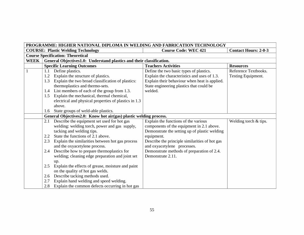
PROGRAMME: HIGHER NATIONAL DIPLOMA IN WELDING AND F ABRICATION TECHNOLOGY COURSE: Plastic Welding Technology Course Code: WEC 421 Contact Hours: 2-0-3 Course Specification: Theoretical WEEK General Objectives1.0: Understand plastics and their classification. Specific Learning Outcomes Teachers Activities Resources 1 1.1 Define plastics.
1.2 Explain the structure of plastics. 1.3 Explain the two broad classification of plastics:
thermoplastics and thermo-sets. 1.4 List members of each of the group from 1.3. 1.5 Explain the mechanical, thermal chemical,
electrical and physical properties of plastics in 1.3 above.
1.6 State groups of weld-able plastics.
Define the two basic types of plastics. Explain the characteristics and uses of 1.3. Explain their behaviour when heat is applied. State engineering plastics that could be welded.
Reference Textbooks. Testing Equipment.
General Objectives2.0: Know hot air(gas) plastic welding process. 2.1 Describe the equipment set used for hot gas
welding: welding torch, power and gas supply, tacking and welding tips.
2.2 State the functions of 2.1 above. 2.3 Explain the similarities between hot gas process
and the oxyacetylene process. 2.4 Describe how to prepare thermoplastics for
welding; cleaning edge preparation and joint set up.
2.5 Explain the effects of grease, moisture and paint on the quality of hot gas welds.
2.6 Describe tacking methods used. 2.7 Explain hand welding and speed welding. 2.8 Explain the common defects occurring in hot gas
Explain the functions of the various components of the equipment in 2.1 above. Demonstrate the setting up of plastic welding equipment. Describe the principle similarities of hot gas and oxyacetylene processes. Demonstrate methods of preparation of 2.4. Demonstrate 2.11.
Welding torch & tips.

56
plastic welding and their prevention. 2.9 Explain the factors that effect the quality of hot
gas weld: i. joint preparation ii. temperature of the welding gas iii. pressure (on rod) iv. quality of base and filler v. skill of welder.
2.10 Describe safety measures in hot gas welding: safety of personnel and equipment.
2.11 Carry out welding in butt and fillet joints. General Objectives3.0: Know other plastic welding processes. 3.1 List other plastic welding processes: hot plate,
electric fusion, ultrasonic friction and vibration processes.
3.2 Explain the principles and practice of the processes listed in 3.1 above.
3.3 Explain plastics that could be weld using processes in 3.1.
Explain the four factors that may affect the quality of weld. Carry out plastic welding using appropriate methods.
Plastic welding equipments.
General Objectives4.0: Understand inspection and evaluation of plastic welds. 4.1 Explain the importance of testing weld.
4.2 State the three broad groups of plastics weld testing:
i. Destructive: tensile, bend, impact testing and filler rod removal;
ii. Non-destructive: visual, leak, spark and radiographic tests.
4.3 Explain the factors affecting the strength of welds done with hot gas process e.g. temperature,
Enumerate reasons for weld testing. Explain the following factors that may affect the strength of the weld:
- Strength of the weld. - temperature of the welding gas. - pressure on welding rod during
welding. - type of welding. - preparation of plastic edge before
Welding Machines. Welded Joints. Specimens/Models. Testing Equipment.

57
pressure and skill. 4.4 Carry out plastic weld testing and evaluation
using appropriate methods.
welding. - skill of welder.

58
PROGRAMME: HIGHER NATIONAL DIPLOMA IN WELDING AND F ABRICATION TECHNOLOGY COURSE: Weld Inspection & Control III Course Code: WEC 422 Contact Hours: 2L Course Specification: Theoretical Course WEEK General Objectives1.0: Understand Welding Codes & Standards Specific Learning Outcomes Teachers Activities Resources 1-3
1.5 Understand classes of standards & codes in welding.
1.6 Identify acceptance criteria as per standard codes.
1.7 Understanding Inspection & control of pre-fabricated materials.
1.8 Understanding inspection & control of manufacturing processes.
Explain and confirm students understanding of classes & Inspection & control procedures.
1. ANSI/AWS D1.1 Structural welding code.
2. BS 1295 Pipe code. 3. ASTMIX Welding
Code 4. Ap1 1104 5. ASME B31.1 Power
piping code. General Objectives2.0: Understand Duties and roles of weld inspection professional 4-7 2.1 Understand duty of inspector under the following:
• Interpretation of drawings & specifications; • Qualification of procedure and welder; • Checking the application of approved welding
procedure; • Selection of production test samples; • Evaluation of Test results. 2.2 Explain the categories, essential requirements &
desirable characteristics of an inspector.
Explain and confirm students understanding of objectives. Ask students to interpret drawing specification and welding procedure.
-
General Objectives3.0: Understand some special procedures Requirements in Weld Inspection 7-10 3.1 Define pre-heating treatments.
3.2 Explain inter-pass temperature control. 3.3 Define post-heating treatments.
Explain why special heat treatment procedures are required in codes.
-

59
General Objectives4.0: Understand the Preparation of Weld Procedures & Welders Qualification 4.1 Identify codes for specific welding jobs.
4.2 Understand how to write procedures for welding operation.
4.3 Explain how to prepare welders Qualification test samples.
4.4 Explain how to evaluate a weld procedure specification.
Confirm students understanding of procedures explained in 4.1-4.4. Test students’ ability to perform objectives.
-

60
PROGRAMME: HIGHER NATIONAL DIPLOMA IN WELDING AND F ABRICATION TECHNOLOGY COURSE: Underwater Welding & Cutting Course Code: WEC 423 Contact Hours: 2-0-3 Course Specification: Theoretical Content WEEK General Objectives1.0: Understand underwater welding. Specific Learning Outcomes Teachers Activities Resources 1-3 1.1 Define underwater welding process.
1.2 Discuss the equipment used under the following: - power source - positive operating safety
switch - electrode holder - protective clothing - earthing.
1.3 State the procedure for underwater welding. 1.4 Compare weld produced underwater with that
done on surface in terms of ductility and strength. 1.5 Explain why fillet welds are usually
recommended for all underwater welding.
Explain underwater welding process. With sketches/diagrams where necessary describe the equipments used in underwater welding. State underwater welding process and the operating principles of shielded metal arc welding. Explain the welding processes and technique, materials and preparation:
- self consuming technique.
- manipulative technique.
Explain the following: - under welding
arcs; - adverse
conditions - underwater
welding limitations;
- underwater fillet welds/strength.

61
General Objectives2.0: Understand underwater cutting. 4-6 2.1 State the principles of operation for underwater
cutting. 2.2 State the various underwater cutting processes. 2.3 State the main gas used in underwater cutting. 2.4 Explain how to light the torch on land. 2.5 Explain how the lighted torch my be lowered
underwater. 2.6 Explain how to light the torch underwater. 2.7 Describe the actual cutting operation using either
arc or gas process. 2.8 Explain the difference between underwater
cutting torch and surface cutting torch. 2.9 Explain how the cutting flame will be tested
before passing it on to the diver. 2.10 Explain the meaning of the term “drag technique”
in underwater cutting. 2.11 State on the points to remember always.
Explain underwater cutting and various processes. Describe the operating principles of:
- oxygen arc cutting;
- shielded metal arc cutting
- thermic lance. Mention the gas used and its importance. Explain torch lighting underwater. With diagrammatic illustrations describe cutting operation using arc and gas. Explain the difference between underwater torch and surface cutting torch. List the materials used for various techniques e.g.:
- steel tubular electrodes;
- ultrathermic electrodes.
Enumerate the important points to remember.
Electrodes and Cutting Tools.
General Objectives3.0: Know the safety precautions to be observed in underwater welding cutting operations. 7-8 3.1 State the sources of hazards in underwater
welding and cutting. 3.2 State the all safety precautions to be observed
during underwater welding and cutting.
Explain the general precautions for arc cutting and welding. Explain sources of hazards of:
� topside operation of arc cutting and welding.
� electrode holds and cutting torches.
O.H.P. & Transparencies. Video Documentaries.
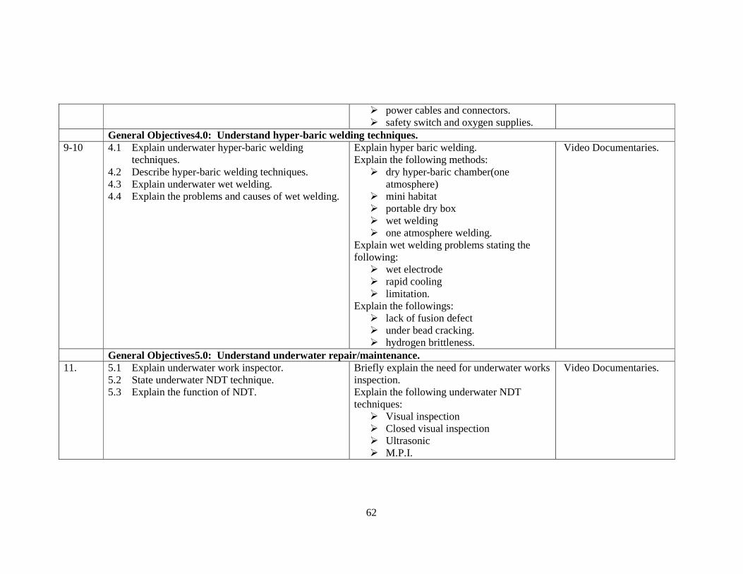
62
� power cables and connectors. � safety switch and oxygen supplies.
General Objectives4.0: Understand hyper-baric welding techniques. 9-10 4.1 Explain underwater hyper-baric welding
techniques. 4.2 Describe hyper-baric welding techniques. 4.3 Explain underwater wet welding. 4.4 Explain the problems and causes of wet welding.
Explain hyper baric welding. Explain the following methods:
� dry hyper-baric chamber(one atmosphere)
� mini habitat � portable dry box � wet welding � one atmosphere welding.
Explain wet welding problems stating the following:
� wet electrode � rapid cooling � limitation.
Explain the followings: � lack of fusion defect � under bead cracking. � hydrogen brittleness.
Video Documentaries.
General Objectives5.0: Understand underwater repair/maintenance. 11. 5.1 Explain underwater work inspector.
5.2 State underwater NDT technique. 5.3 Explain the function of NDT.
Briefly explain the need for underwater works inspection. Explain the following underwater NDT techniques:
� Visual inspection � Closed visual inspection � Ultrasonic � M.P.I.
Video Documentaries.

63
� X-Ray. Explain repair procedure and underwater activities using:
� underwater welding technique � NDT inspections � State reasons for choosing NDT
technique. General objective 6.0: Understand underwater repair works and maintenance. 12-15 6.1 Explain standards and weld specification.
6.2 Give the function of classification societies. 6.3 Describe repair procedure and techniques. 6.4 Explain report working skills.
Explain the importance of specifications. State the relevant agencies:
� API � Lloyd Register of shipping � B.S.
Explain repair procedure and underwater activities such as:
� wet welding � hyper-baric techniques � NDT inspections
State the step by step technical report working for:
� underwater inspection � equipment and component uses � observation and suggestions.
Video Documentaries.

64
PROGRAMME: HIGHER NATIONAL DIPLOMA IN WELDING AND F ABRICATION TECHNOLOGY COURSE: Material and Process Selection Course Code: WEC 424 Contact Hours: 2-0-3 Course Specification: Theoretical WEEK General Objectives1.0: Know factors involved in materials selection. Specific Learning Outcomes Teachers Activities Resources 1 1.1 Describe the following factors that affect
materials selection for fabrication purposes: � Materials properties (weld-ability, strength, etc.) � Materials data � Cost � Reliability and Safety. 1.2 State sources of data on materials (e.g. standard
handbook, manufacturers’ data sheets, reference books, etc.).
1.3 Define reliability. 1.4 State elements of reliability considered in
selection. 1.5 Define “factor of safety”. 1.6 Explain its relevance in materials selection.
Explain the factors involved in materials selection (economic availability, ease of fabrication, cost). Explain types of engineering materials and their features. Explain how reliability & factor of safety affect material selection. Give exercises.
Standards. Handbooks. Manufacturers Data Book.
General Objectives2.0: Understand the relationship between performance in service and materials properties. 2.1 Describe the stresses to which pipe lines and
other welded structures are subjected. 2.2 State the mechanical properties required to
counteract them. 2.3 Explain the role played by the following material
properties on performance: � Ultimate tensile strength or maximum stress. � young’s modulus � ductility/malleability
Explain the properties of engineering materials in mechanical, chemical, physical, dimensional, electrical, etc. Give expressions relating properties to measurable quantities. Explain how the properties can serve as a classifier for materials. Give exercises.

65
� toughness � fatigue strength � Susceptibility to chemical corrosion. 2.4 State materials that could be used in sheet metal
fabrication. 2.5 Explain the relevance of the following properties
on the formability of sheet metals used in fabrications:
� deep drawability � Stretch-ability.
General Objectives3.0: Understand the relationship between the process selected and materials properties. 3.1 Describe joining processes.
3.2 State the joining processes applicable to the following materials:
� plain carbon steel � low alloy steel � heat resisting steel � aluminium and its alloys � cast iron � stainless steel. � dissimilar materials. 3.3 Explain the welding techniques to be employed
when welding a project that will operate at low or high temperature.
3.4 State the properties of metals that can operate at: � low temperature condition � high temperature condition. 3.5 Explain the importance of knowing the service
condition of a project before selecting a metal and
Categorise welding processes. Explain the features of the above processes, their advantages and drawbacks. Select specific applications. Demonstrate the process of selecting a material and joining process. Give assignment on material and process selection for particular applications.
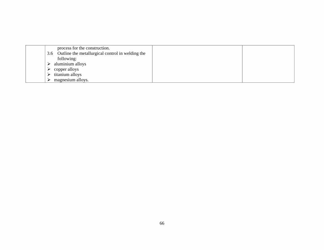
66
process for the construction. 3.6 Outline the metallurgical control in welding the
following: � aluminium alloys � copper alloys � titanium alloys � magnesium alloys.
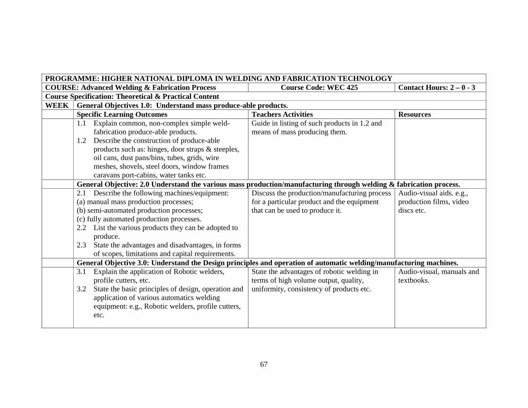
67
PROGRAMME: HIGHER NATIONAL DIPLOMA IN WELDING AND F ABRICATION TECHNOLOGY COURSE: Advanced Welding & Fabrication Process Course Code: WEC 425 Contact Hours: 2 – 0 - 3 Course Specification: Theoretical & Practical Content WEEK General Objectives 1.0: Understand mass produce-able products. Specific Learning Outcomes Teachers Activities Resources 1.1 Explain common, non-complex simple weld-
fabrication produce-able products. 1.2 Describe the construction of produce-able
products such as: hinges, door straps & steeples, oil cans, dust pans/bins, tubes, grids, wire meshes, shovels, steel doors, window frames caravans port-cabins, water tanks etc.
Guide in listing of such products in 1.2 and means of mass producing them.
General Objective: 2.0 Understand the various mass production/manufacturing through welding & fabricat ion process. 2.1 Describe the following machines/equipment:
(a) manual mass production processes; (b) semi-automated production processes; (c) fully automated production processes. 2.2 List the various products they can be adopted to
produce. 2.3 State the advantages and disadvantages, in forms
of scopes, limitations and capital requirements.
Discuss the production/manufacturing process for a particular product and the equipment that can be used to produce it.
Audio-visual aids. e.g., production films, video discs etc.
General Objective 3.0: Understand the Design principles and operation of automatic welding/manufacturing machines. 3.1 Explain the application of Robotic welders,
profile cutters, etc. 3.2 State the basic principles of design, operation and
application of various automatics welding equipment: e.g., Robotic welders, profile cutters, etc.
State the advantages of robotic welding in terms of high volume output, quality, uniformity, consistency of products etc.
Audio-visual, manuals and textbooks.

68
General Objective: 4.0 Understand welding and fabrication automation tools. 4.1 Explain the application of CAD and CAM tools.
4.2 Describe welding & fabrication processes in mass production and manufacturing with the following equipment:
(a) Robotic welders; (b) EDM; (c) Electric Discharge Cutting (EDC); (d) Profilers & Shapers; (e) Laser Cutters and welders etc.
Discuss choice of software. Lab/workshop Audio-visual.
General Objective: 5.0 Knowledge Application Mass Welding Fabrication Manufacturing & Production Aids & Tools 5.1 Explain the transformation design concepts into
models and prototypes for mass welding production.
5.2 Discuss the choice and application of jigs, fixtures and dies, moulds templates, profilers in mass welding and fabrication production and manufacturing process standards and quality maintenance.
5.3 Explain the application of tolerance and fits in mass welding & fabrication, production and manufacturing process.
Discuss and guide students, Issue assignment on a complete production, manufacturing process for a particular product and what equipment that can be used.
Audio-visual aids. e.g., production films, video discs etc.
General Objective: 6.0 Knowledge of Application of Mass Welding & Fabrication Surface Finishing Methods 6.1 Explain the importance of surface finishing.
6.2 Describe the following surface finishing methods: painting, ceramic and enamel coating, electroplating, galvanizing, polishing etc c. choice of surface finishing systems.
List surface finishing methods. Discuss surface finishing in terms of aesthetics, protection and ergonomic impartation to products.
Workshop.

69
General Objective: 7.0 Understand the application of mass welding & fabrication production economics 7.1 Explain cost analysis elements in mass welding &
fabrication production and manufacturing. 7.2 Describe the formulation and application of cost
indices. 7.3 Explain Cost/Time shrinking methods in terms of
planning, scheduling sequencing, layouts, material control and mgt., products storage, packaging and delivery.
7.4 Discuss the application of work study and ergonomics in time/cost shrinking.
7.5 Explain the various computer-based welding production and planning software e.g. Weldplan III from FORCE Technology UK.
Discuss production procedures of welding/fabrication, processes in terms of costing, material, logistics, energy etc. Discuss the use of software packages in welding for production planning.
General Objective 8.0: Understand entrepreneurship in welding and fabrication production. 8.1 Explain the following:
a). Job/contract tendering and bidding b). Contract laws and business ethics c). Feasibility report writing d). Funds syndicating e). Financial risk management f). Sales, marketing, production techniques, product modeling/manipulation (modeling and remodeling).
Guide in the preparation of a feasibility report of a product. Discuss sale, marketing and promotion techniques.

70
LIST OF EQUIPMENTS/TOOLS
(A) WORKSHOPS/STUDIOS
(1) FITTING/MACHINE SHOP FITTING
1. Work benches for 30 Students 10 2. Bench Vices 20 3. Pillar Drilling Machine 1 4. Marking out Table 1 5. Surface plate 2 6. Bench Drilling Machine 1 7. Radial Drilling Machine 1 8. Pedestal Grinding Machine 1 9. Power Hacksaw 1 10. Arbor Press 1 11. Flat Rough File (300mm) 20 12. Round (Rough & Smooth) File (300mm) 20each 13. Square Rough File (300mm) 20 14. Flat Smooth File (250mm) 20 15. Half-Round Rough File (150mm) 20 16. Triangular Rough File (150mm) 20 17. Half-Round Smooth File (250mm) 20 18. Triangular Smooth File (150mm) 20 19. Try Square 20 20. Dividers 20 21. Wallet of Wording File 10 sets 22. Scribers 10 23. Vee Block and Clamp 2
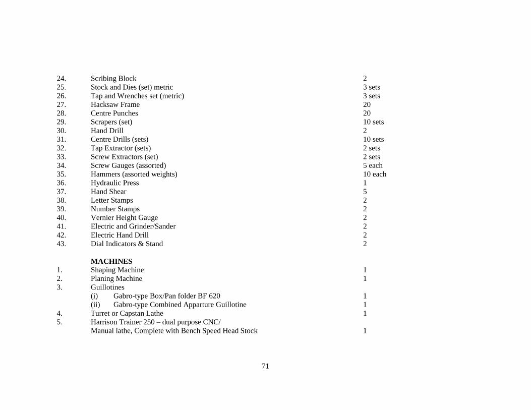
71
24. Scribing Block 2 25. Stock and Dies (set) metric 3 sets 26. Tap and Wrenches set (metric) 3 sets 27. Hacksaw Frame 20 28. Centre Punches 20 29. Scrapers (set) 10 sets 30. Hand Drill 2 31. Centre Drills (sets) 10 sets 32. Tap Extractor (sets) 2 sets 33. Screw Extractors (set) 2 sets 34. Screw Gauges (assorted) 5 each 35. Hammers (assorted weights) 10 each 36. Hydraulic Press 1 37. Hand Shear 5 38. Letter Stamps 2 39. Number Stamps 2 40. Vernier Height Gauge 2 41. Electric and Grinder/Sander 2 42. Electric Hand Drill 2 43. Dial Indicators & Stand 2 MACHINES 1. Shaping Machine 1 2. Planing Machine 1 3. Guillotines (i) Gabro-type Box/Pan folder BF 620 1 (ii) Gabro-type Combined Apparture Guillotine 1 4. Turret or Capstan Lathe 1 5. Harrison Trainer 250 – dual purpose CNC/ Manual lathe, Complete with Bench Speed Head Stock 1

72
6. Bench Lathe (Melcer -3 model) 1 7. Riveting Machine 1 8. Pliers (Engineer’s Combination, multi-groove, vice grip, diagonal cutting, Long nose, slide cutting) 6 each 9. Screw Driver (i) Standard Tip (6 x 100mm) 5 (ii) Standard Tip (4 x 400mm) 5 (iii) Offset Straight Up 1 & 2 5 each (iv) Straight Tip Spring Chip (12 x 150mm) 5 (v) Philips (2 – 6mm) 5 each 10. Spanners (i) BSW Spanner & Wrench 5 sets (ii) Open-Ended Spanner sets British Whitworth set (metric) 3 sets (iii) Ring Spanner Sets 3 sets (iv) Miniature Spanner Set 3 sets (v) Socket Spanner Set (12mm drive) 3 each 11. Micrometers (three sizes with capacities 0 – 25mm – 50mm 50 – 75mm) outside & inside sets 3 each
(2) FABRICATION/WELDING/HEAT TREATMENT WORKSHOP (i) Welding Section
1. Spot Welding Machine 5 2. TIG Welding Machine 5 3. Manual Arc Welding Machine 5 4. MIG/MAG Welding Machine 5 5. Welding Machine Generator 5 6. Welding Machine Transformer 5 7. Oxygen Cylinders 5

73
8. Acetylene Cylinders 5 9. Argon Cylinders 5 10. CO2 5 11. Oxy-Acetylene Welding Manifold 10 12. Weld Joint Teaching Aids (Diagrams) 3 13. Apron 30 14. Hand Gloves 30 pairs 15. Welding Head Shield 30 16. Electrode Oven 1 17. Work Benches for each Welding Machine 20 18. Portable Profile Gas Gutting Machine 1 19. Soldering Iron 10 20. Oxy-Acetylene Regulators 5 each 21. Booth Screen 20 22. Gas Welding Goggles 20 23. Electrode Holder 30 24. Welding Chipping Hammer 15 25. Wire Brush (bench type) 10 26. Gas Cylinder Trolley 2 27. Spark Lighter 56 28. Brazing Rods 10kg 29. Soldering Flux 10 tins 30. Bending Machine for Testing Welds 1 31. Flash Welding Machine 1 32. Submerge-Arc Welding Machine 1 33. Plastic Welding Machine 1 34. Profile Heavy Duty Cutter Gas 1 35. Gas Welding Blow Pipe 5 36. Gas Welding Cutting Blow Pipe 5 37. Oxy-Acetylene Welding Hoses 30 metres each

74
38. MAG (CO2) Regulator 5 39. Welding Face Shield 20 40. Argon Regulator 5 41. Leggings 10 pairs 42. Safety Charts Assorted (ii) Fabrication Section
1. Hand Drilling Machine 2 2. Jig Saw Cutting Machine 2 3. Vernier Calliper 4 4. Calibrated Try Square 5 5. Callipers 4 6. Sup Shear 2 7. Tool Boxes containing Flat Spanners and Socket Spanners 2 8. Panel Beating Tool Set 4 sets 9. Number Stamp 1 sets 10. Giant Ring Spanners 4 11. Long Nose Pliers 5 12. Shifting Pliers 1 13. Allen Keys 10 14. Sledge Hammer 2 15. Giant Socket Spanners 4 16. Bench Grinding Machine 5 17. Anvil and Stand 5 18. Clamp 5 19. Steel Rule 4 20. Twist Drill Set 10 21. Power Saw Cutting Machine 4 sets

75
22. Pipe and Flange Cutting Machine 2 23. Band Saw Machine 2 24. Hand Shearing Machine 1 25. Guillotine Cutting Machine 1 26. Manual Drilling Machine 1 27. Air Compressor 1 28. Break Press Machine 1 29. Screw Press 2 30. Pipe Bending Machine 2 31. Table Tool Grinder 1 32. Work Bench (Wood) 10 33. Work Bench (Metal) 10 34. Vices 30 35. Marking off Table 1 36. Snap Rod Cutter 1 37. Auto Body Fender Set 2 38. Erichsen Cupping Test Machine 1 (iii) Heat Treatment 1. Medium Size Muffle Furnace (0 – 1200 0C) 1 2. Metal Tong 5 3. Thermocouples (assorted) 1 each 4. Pyrometer (optical type) 1 5. Quenching Bath (oil, water, salt solution) Thermostatically controlled. 1 each 6. Salt Bath Furnace (oil fired) 1 7. Cooling Curve Determination Set 1 8. Jominy End-Quench Test Apparatus 1

76
(iv) Engineering Drawing Studio 1. Drawing Table complete with Drafting Machine 2 2. Drawing Board with Tee Squares 30 3. Adjustable Set Squares 2 4. Desk Sharpener 4 5. Scale Rule (triangular and flat) 2 each 6. Black Board Rule 2 7. Black Board Set Square (450, 600) 2 each 8. Black Board Protractor 2 9. Black Board Compasses 2 10. French Curve 2 11. Letter and Number Stencils 2mm, 4mm, 5mm, 7mm, 8mm and 10mm 2 each (v) Computer Studio * Not less than (30 nos.) computer sets should be available for software practice.
(B) LABORATORIES (i) Metallography 1. Metallurgical Microscope (bench type) 2 2. Metallurgical Microscope with built-in transformer And rheostat accessories; 1 (i) Telescope Camera 1 (ii) Films 20 pkts (iii) Development Paper 20 pkts 3. Grinding and Polishing Rotary Machine,

77
203mm wheel, 50 – 500rpm. 2 4. Spare Aluminium Wheel (230mm) for item 3 above 2 5. Four (4) Stage Roll Hand Grinder with water flow 2 6. Grinding Paper (Silicon Carbide) with grits 240, 320, 600, 800 3 pkts each. 7. Metallurgical Sample mounting hydraulic press with Accessories and thermostatically controlled heater 1 8. Paper Disc, 203mm with PSA adhesive back 10 9. Polishing Cloths (micro cloths) 2 pkts 10. Phenolic Powder Dispenser 1 tin 11. Mould Release (Silicone) 1 12. Polishing Powder A1-203 (0.3 micron) 2 tins ,, ,, ,, (0.5 micron) 2 tins ,, ,, ,, (1.0 micron) 2 tins 13. Polishing Suspension CO2O3 (1.0 micron) 1 tin 14. Desiccators Specimen Cabinet 1 15. Cold/Hot Blower (hand operated) 2 16. Etching Reagents (Nital, Ferric Chloride, diluted Sulphuric Acid, diluted Hydrochloric Acid) Assorted 17. Fume Cup-Board 1 (ii) Material Testing Laboratory
(A) DESTRUCTIVE TESTING
1. Floor Mounted Universal Tensile/Compressive Testing Machine With accessories, with loading capacity up to 100KN 1 2. Table Top Tensometer with accessories 1 3. Impact Testing Machine (Izod, Charpy) 1 4. Macro-hardness Testing Machine with accessories

78
(Brinell, Vickers and Rockwell). 1 each 5. Metal cutting-off disc machine 1 6. Macro-hardness Testing Machine 1
(B) NON – DESTRUCTIVE TESTING 7. Dye Penetrant Testing Facility with accessories 1 8. Magnetic Flux Testing Facility with accessories 1 9. Electrical Resistance Testing Facility 1 10. Ultrasonic Testing Equipment with accessories 1 11. Radiography Testing Equipment with accessories 1 (iii) Metrology Laboratory 1. Sine Bars 3 2. Slip Gauges 4 3. Depth Gauges (1/20, 200 mml) 15 4. Vernier Callipers 15 5. Slide Gauges with dial indicators 10 6. Micrometer Screw Gauge (100mm – 200mm) 10 7. Universal Dial Gauge Stand 5 8. Angle Gauges (200 - 300) 5 9. Steel Measure (500mm length) 5 10. Spring headed pointed callipers 10 11. Steel Measuring Tapes (2 metres) 5 12. Inside and Outside Callipers 10 13. Screw Drivers (set of various types) 4 sets 14. Vibratory Engraver 2 15. Horizontal and Vertical Comparator 1 16. Surface Measuring Instrument (tally surf) 1

79
17. Roundness Measuring Instrument (tally round) 1 18. Flatness Inter Ferro-meter 1 19. Optical Bevel Protractor 1 20. Tool Makers Microscope 1 21. Universal Pitch Measuring Machine 1 22. Universal Gear Measuring Machine 1 (iv) Strength of Materials Laboratory 1. Shear Force Apparatus 1 2. Bending Moment Apparatus 1 3. Gyroscope Apparatus 1 4. Polygon of Force Apparatus 1 5. Young’s Modulus Apparatus 1 6. Thick Cylinder Apparatus 1 7. Thin Cylinder Apparatus 1 8. Strut Rig Apparatus 1 9. Universal Cantilever Apparatus 1 10. Beam Apparatus 1 11. Closed Coiled Spring Apparatus 1 12. Leaf Spring Testing Machine 1 13. Static and Dynamic Balance Apparatus 1 14. Universal Vibration Apparatus 1 (v) Thermodynamics/Fluids Mechanics Laboratory 1. Hydraulics Bench with accessories for various experiments in fluid flow measurements 1 2. Floating Body Apparatus 2 3. Manometer 1

80
4. Rotameter 1 5. Laminar Flow Apparatus 1 6. Pilot Static Tube 1 7. Water meter 2 8. Weir Tank 2 9. Water water/stirrer unit with bath 1 10. Resistance Thermometer 1 11. Uncalibrated Mercury in glass thermometer 10 – 1100C 25 12. Bomb Calorimeter 1 13. Boyle Gas Calorimeter 1 14. Grant Gas Analyser 1 15. Tacheometer 1 16. Stroboscope 1 17. Thermal Conductivity Apparatus 1 18. Marcet Boiler 1 19. Laboratory Size Steam Boiler Plant 1 20. Mechanical Equivalent of Heat Apparatus 1 21. Vapour density apparatus 1 22. Falling ball viscometer 1 23. Rotary viscometer 1 24. Thermal anemometer 1 25. Electric anemometer 1 26. Air thermometer (constant-volume) 1 27. Pyrometer (Infra-red type) 1 28. Universal radial flow apparatus 1 29. Free and force vortices apparatus 1 30. Lossess in fitting and pipe bending apparatus 1 31. Friction loss in pipes apparatus 1 32. Bernoulis apparatus 1

81
(vi) Electrical Machines & Power Laboratory
(A) MACHINES
1. Motor generator sets for laboratory use (DC supply source) 2 units 2. Tachogenerator 5 units 3. DC Motors: Series 3 Shunt 3 Compound 3 4. DC Generators: (a) Self excited 3 (capable of being (b) Compound connected as a, b, c & d) 5. AC Motors: - Single phase induction motors (assorted) 5 - 3- phase induction motor 3 - Dynamomet set 2 units - Direct on line starters 4 - Star delta starters 4 - Auto transformer starter 1 6. Transformers: - Demonstration unit 1 - Single phase 4 sets - 3 phase 4 7. Variable Resistance Load 5 8. Variable Inductive Load 5 9. Variable Capacitive Load 2 10. Machine control panel trainer unit 1 11. A/C Machines: - Synchronous machines 2
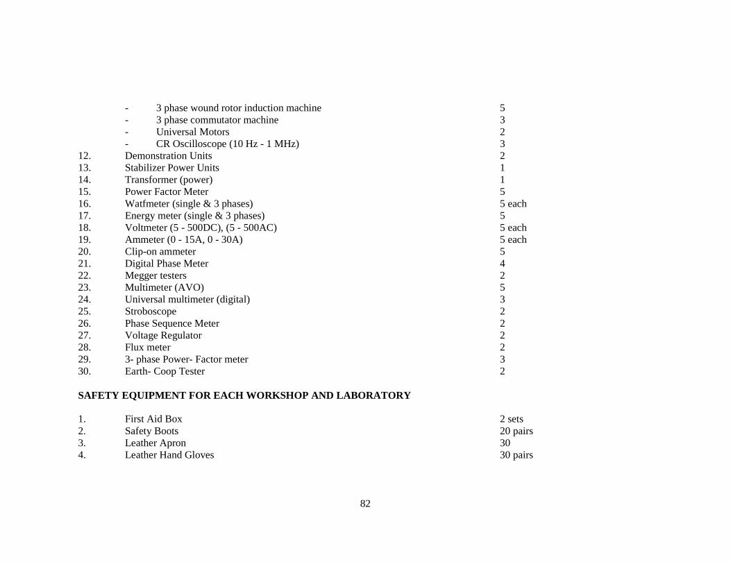
82
- 3 phase wound rotor induction machine 5 - 3 phase commutator machine 3 - Universal Motors 2 - CR Oscilloscope (10 Hz - 1 MHz) 3 12. Demonstration Units 2 13. Stabilizer Power Units 1 14. Transformer (power) 1 15. Power Factor Meter 5 16. Watfmeter (single & 3 phases) 5 each 17. Energy meter (single & 3 phases) 5 18. Voltmeter (5 - 500DC), (5 - 500AC) 5 each 19. Ammeter (0 - 15A, 0 - 30A) 5 each 20. Clip-on ammeter 5 21. Digital Phase Meter 4 22. Megger testers 2 23. Multimeter (AVO) 5 24. Universal multimeter (digital) 3 25. Stroboscope 2 26. Phase Sequence Meter 2 27. Voltage Regulator 2 28. Flux meter 2 29. 3- phase Power- Factor meter 3 30. Earth- Coop Tester 2 SAFETY EQUIPMENT FOR EACH WORKSHOP AND LABORATORY 1. First Aid Box 2 sets 2. Safety Boots 20 pairs 3. Leather Apron 30 4. Leather Hand Gloves 30 pairs

83
5. Fire Extinguishers 30 6. Sand Buckets 30 7. Safety Charts and Drawings assorted.
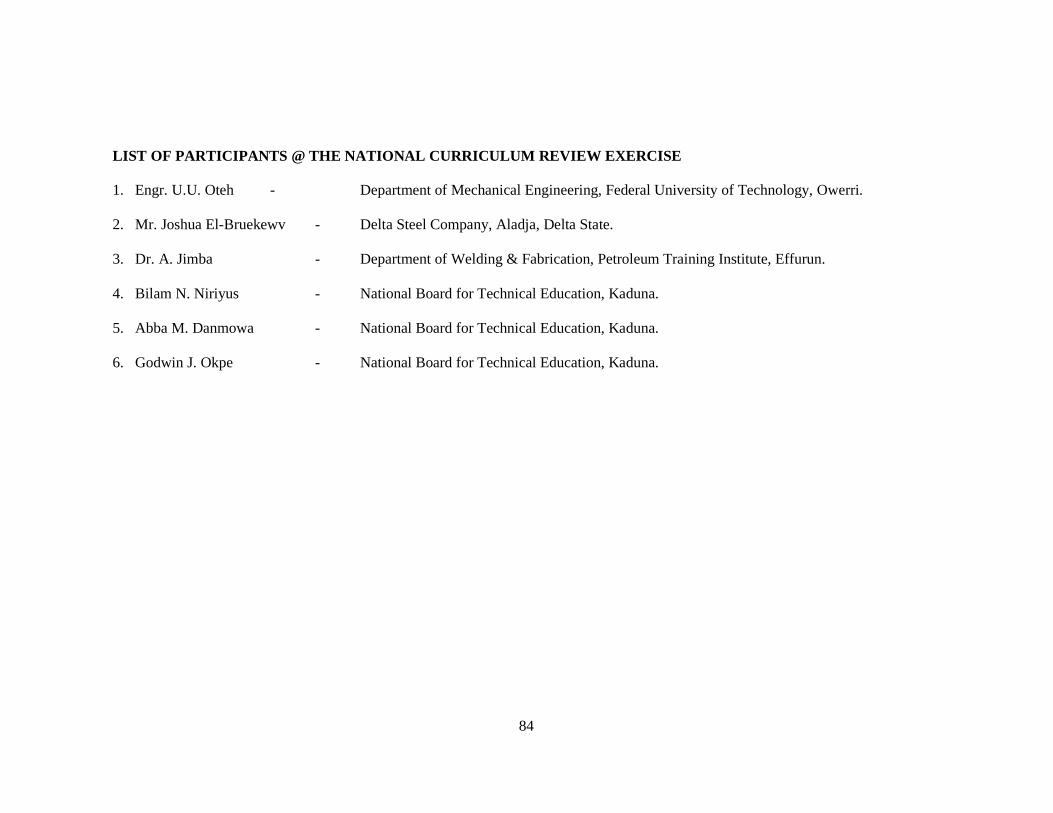
84
LIST OF PARTICIPANTS @ THE NATIONAL CURRICULUM REVI EW EXERCISE 1. Engr. U.U. Oteh - Department of Mechanical Engineering, Federal University of Technology, Owerri. 2. Mr. Joshua El-Bruekewv - Delta Steel Company, Aladja, Delta State. 3. Dr. A. Jimba - Department of Welding & Fabrication, Petroleum Training Institute, Effurun. 4. Bilam N. Niriyus - National Board for Technical Education, Kaduna. 5. Abba M. Danmowa - National Board for Technical Education, Kaduna. 6. Godwin J. Okpe - National Board for Technical Education, Kaduna.