high-temperature behaviour of in 738 lc under isothermal and thermo-mechanical cyclic loading
TRANSCRIPT
ELSEVIER Materials Science and Engineering A230 (1997) 49-57
MATERIAlS SCIENCE &
E~CWEERIWG
A
High-temperature behaviour of IN 738 LC under isothermal and thermo-mechanical cyclic loading
H. Frenz, J. Meersmann, J. Ziebs *, H.-J. Kiihn, R. Sievert, J. Olschewski Bundesanstalt fiir Materialforschung und -prCfung (BAM), Unter den Eic>hen 87, D-12205 Berlin, Germmy
Received 15 July 1996; received in revised form 24 December 1996
Abstract
The temperature dependence of the cyclic behavior of IN 738 LC was studied. Cyclic iso- and non-isothermal tests were performed with proportional and non-proportional tension/torsion strain paths. It was shown that maximum and minimum stress values measured in isothermal strain controlled tests correspond quite well with results of non-isothermal tests. Thermal-mechan- ical constitutive equations based on the viscoplastic Chaboche model were used to describe the non-isothermal stress-strain behavior. 0 1997 Elsevier Science S.A.
Keywords: Nickel-base superalloy IN 738 LC; Thermo-mechanical cyclic behavior; Uni- and multiaxial loading; Constitutive relations; Viscoplastic Chaboche model
1. Introduction
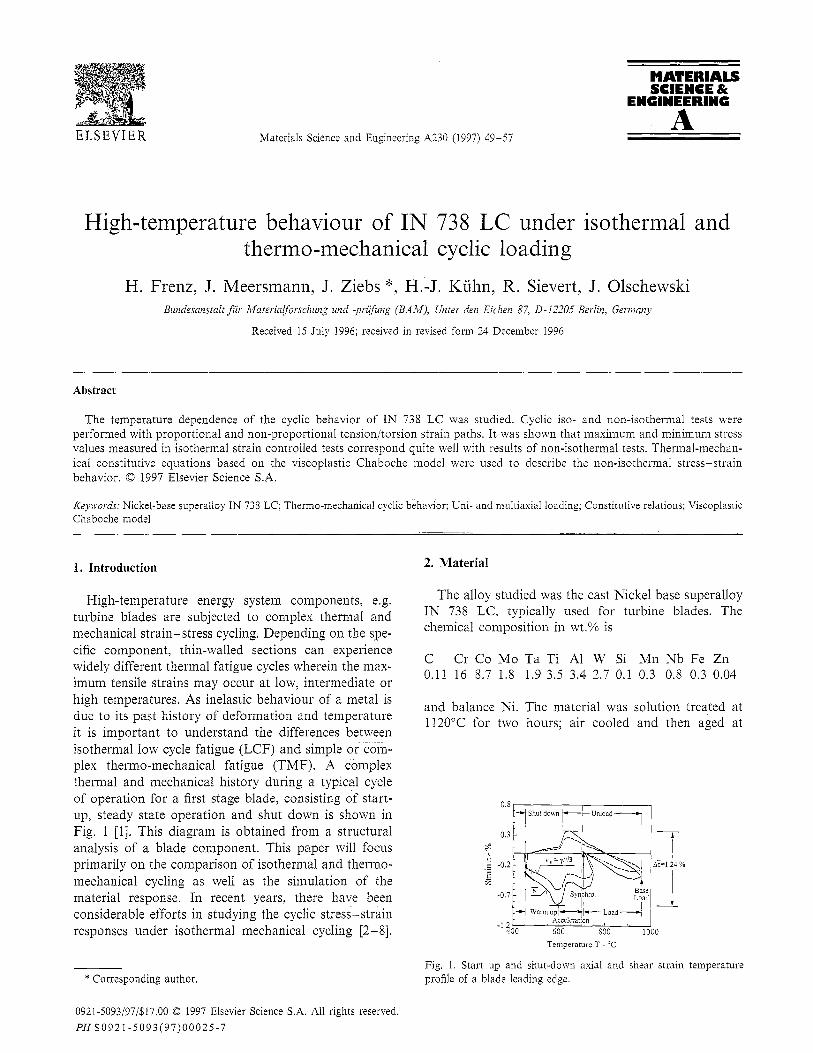
High-temperature energy system components, e.g. turbine blades are subjected to complex thermal and mechanical strain-stress cycling. Depending on the spe- cific component, thin-walled sections can experience widely different thermal fatigue cycles wherein the max- imum tensile strains may occur at low, intermediate or high temperatures. As inelastic behaviour of a metal is due to its past history of deformation and temperature it is important to understand the differences between isothermal low cycle fatigue (LCF) and simple or com- plex thermo-mechanical fatigue (TMF). A complex thermal and mechanical history during a typical cycle of operation for a first stage blade, consisting of start- up, steady state operation and shut down is shown in Fig. 1 [l]. This diagram is obtained from a structural analysis of a blade component. This paper will focus primarily on the comparison of isothermal and thermo- mechanical cycling as well as the simulation of the material response. In recent years, there have been considerable efforts in studying the cyclic stress-strain responses under isothermal mechanical cycling [2-Q.
* Corresponding author.
2. Material
The alloy studied was the cast Nickel base superalloy IN 738 LC, typically used for turbine blades. The chemical composition in wt.% is
C Cr Co MO Ta Ti Al W Si Mn Nb Fe Zn 0.11 16 8.7 1.8 1.9 3.5 3.4 2.7 0.1 0.3 0.8 0.3 0.04
and balance Ni. The material was solution treated at 1120°C for two hours; air cooled and then aged at
Temperature T - ‘C
Fig. 1. Start up and shut-down axial and shear strain temperature profile of a blade leading edge.
0921-5093/97/$17.00 8 1997 Elsevier Science S.A. All rights reserved. P11s0921-5093(97)00025-7
’ f
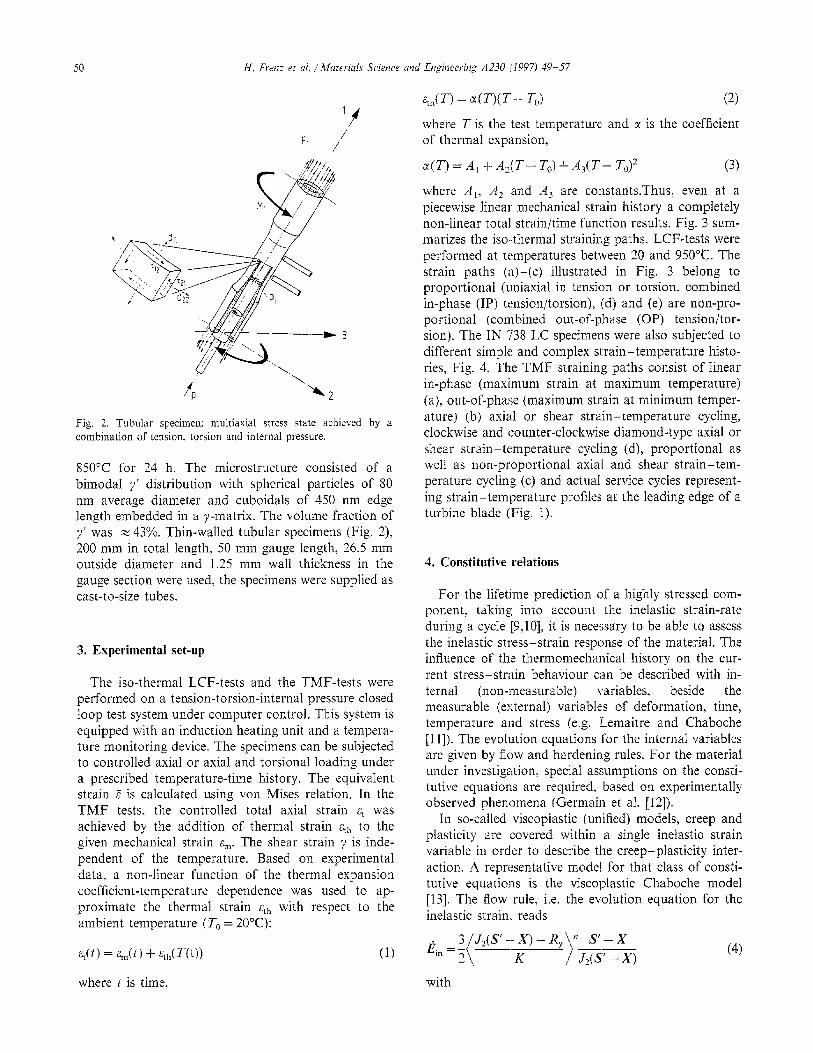
Fig. 2. Tubular specimen: multiaxial stress state achieved by a combination of tension, torsion and internal pressure.
850°C for 24 h. The microstructure consisted of a bimodal y’ distribution with spherical particles of 80 nm average diameter and cuboidals of 450 nm edge length embedded in a y-matrix. The volume fraction of y’ was z 43%. Thin-walled tubular specimens (Fig. 2), 200 mm in total length, 50 mm gauge length, 24.5 mm outside diameter and 1.25 mm wall thickness in the gauge section were used, the specimens were supplied as cast-to-size tubes.
3. Experimental set-up
The iso-thermal LCF-tests and the TMF-tests were performed on a tension-torsion-internal pressure closed loop test system under computer control. This system is equipped with an induction heating unit and a tempera- ture monitoring device. The specimens can be subjected to controlled axial or axial and torsional loading under a prescribed temperature-time history. The equivalent strain E is calculated using von Mises relation. In the TMF tests, the controlled total axial strain & was achieved by the addition of thermal strain qh to the given mechanical strain L. The shear strain 7 is inde- pendent of the temperature. Based on experimental data. a non-linear function of the thermal expansion coefficient-temperature dependence was used to ap- proximate the thermal strain &h with respect to the ambient temperature (To = 20°C):
QltT) = e-x~- To) (2)
where T is the test temperature and x is the coefficient of thermal expansion,
a(T)=A, +A,(T-T,)-tA,(T- T,)” (3)
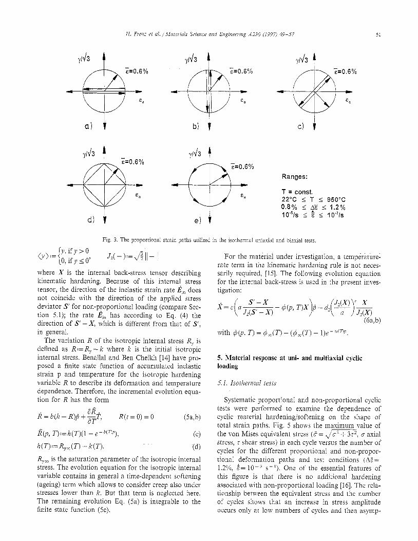
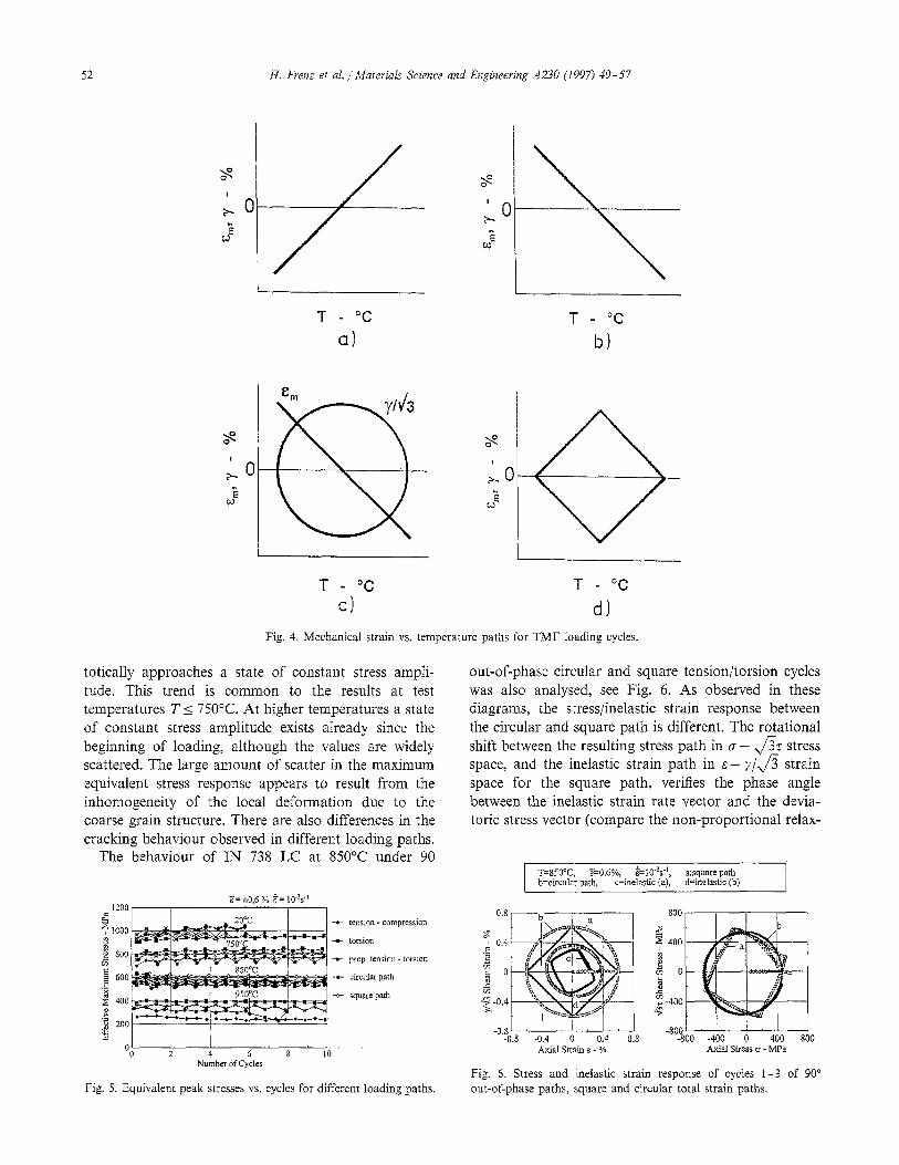
where A,: A, and A, are constants.Thus, even at a piecewise linear mechanical strain history a compIetely non-linear total strain/time function results. Fig. 3 sum- marizes the iso-thermal straining paths. LCF-tests were performed at temperatures between 20 and 950°C. The strain paths (a)-(c) illustrated in Fig. 3 belong to proportional (tmiaxial in tension or torsion, combined in-phase (IP) tension/torsion), (d) and (e) are non-pro- portional (combined out-of-phase (OP) tension/tor- sion). The IN 738 LC specimens were also subjected to different simple and complex strain-temperature histo- ries, Fig. 4. The TMF straining paths consist of linear in-phase (maximum strain at maximum temperature) (a), out-of-phase (maximum strain at minimum temper- ature) (b) axial or shear strain-temperature cycling, clockwise and counter-clockwise diamond-type axial or shear strain-temperature cycling (d), proportional as well as non-proportional axial and shear strain-tem- perature cycling (c) and actual service cycles represent- ing strain-temperature profiles at the leading edge of a turbine blade (Fig. 1).
4. Constitutive relations
For the lifetime prediction of a highly stressed com- ponent? taking into account the inelastic strain-rate during a cycle [9,10]. it is necessary to be able to assess the inelastic stress-strain response of the material. The influence of the thermomechanical history on the cur- rent stress-strain behaviour can be described with in- ternal (non-measurable) variables. beside the measurable (external) variables of deformation, time, temperature and stress (e.g. Lemaitre and Chaboche [I I]). The evolution equations for the internal variables are given by flow and hardening rules. For the material under investigation, special assumptions on the consti- tutive equations are required, based on experimentally observed phenomena (Germain et al. [12]).
In so-called viscoplastic (unified) models, creep and plasticity are covered within a single inelastic strain variable in order to describe the creep-plasticity inter- action. A representative model for that class of consti- tutive equations is the viscoplastic Chaboche model [13]. The flow rule, i.e. the evolution equation for the inelastic strain, reads
n S-X
J&S’ - x)
where t is time, with
(4)
H. Fren; et al. /Materials Science and Engineering AZ30 (1997) 49-57 51
a) f b) t
Ranges:
T = const. 22°C 2 T 2 950°C 0.8% I A’ I 1.2% 1o’5/s I t 5 1 o‘31s
Fig. 3. The proportional strain paths utilized in the isothermal uniaxial and biaxial tests.
()I):= y,
i
if y > 0 0, if y I 0’ J,(-,:=$II-11
where X is the internal back-stress tensor describing kinematic hardening. Because of this internal stress tensor, the direction of the inelastic strain rate ~iii, does not coincide with the direction of the applied stress deviator S’ for non-proportional loading (compare Sec- tion 5.1); the rate ~i’in has according to Eq. (4) the direction of S’ -X, which is different from that of S’, in general.
The variation R of the isotropic internal stress R, is defined as R:= R, - Ic where k is the initial isotropic internal stress. Benallal and Ben Cheikh [14] have pro- posed a finite state function of accumulated inelastic strain p and temperature for the isotropic hardening variable R to describe its deformation and temperature dependence. Therefore, the incremental evolution equa- tion for R has the form
d=b(h-R)o+$$‘, R(t = 0) = 0 (W)
I?(p, T):=h(T)(l - e-b(QJ), cc>
h(T):= R,,(T) -k(T). (4
R,, is the saturation parameter of the isotropic internal stress. The evolution equation for the isotropic internal variable contains in general a time-dependent softening (ageing) term which allows to consider creep also under stresses lower than k. But that term is neglected here. The remaining evolution Eq. (5a) is integrable to the finite state function (5~).
For the material under investigation, a temperature- rate term in the kinematic hardening rule is not neces- sarily required, [15]. The following evolution equation for the internal back-stress is used in the present inves- tigation:
.e=c a i
s-x J,(S’ - X) -#(p,T)X p-d, - -
1’ ?~‘!J~~ bj a,
with d(p, T) = 4,(T) - (d,(T) - l)emWcnp.
5. Material response at uni- and multiaxial cyclic loading
5.1. Isothemnl tests
Systematic proportional and non-proportional cyclic tests were performed to examine the dependence of cyclic material hardening/softening on the shape of total strain paths. Fig. 5 shows the maximum value of the von Mises equivalent stress (5 = ,/m, 0 axial stress, r shear stress) in each cycle versus the number of cycles for the different proportional and non-propor- tional deformation paths and test conditions (A,?= 1.2%, i= 10-3 s-1 ). One of the essential features of this figure is that there is no additional hardening associated with non-proportional loading [16]. The rela- tionship between the equivalent stress and the number of cycles shows that an increase in stress amplitude occurs only at low numbers of cycles and then asymp-
H. Frenz et nl. , Materials Science and Engineering A230 (1997) 49-57
T - “C T - “C
a) b)
T - “C T - “C
cl d)
Fig. 4. Mechanical strain vs. temperature paths for TMF loading cycles.
totically approaches a state of constant stress ampli- tude. This trend is common to the results at test temperatures T I 750°C. At higher temperatures a state of constant stress amplitude exists already since the beginning of loading, although the values are widely scattered. The large amount of scatter in the maximum equivalent stress response appears to result from the inhomogeneity of the local deformation due to the coarse grain structure. There are also differences in the cracking behaviour observed in different loading paths.
The behaviour of IN 738 LC at 850°C under 90
1200
e 1000 B
1 2 800
E D
2 600
2 400 P
g 200
w
tension-compression
torsion
prop. tension . iorsion
circulv path
square path
I I I i 2 4 6 8 ld
Number of Cycles
Fig. 5. Equivalent peak stresses vs. cycles for different loading paths.
out-of-phase circular and square tension/torsion cycles was also analysed, see Fig. 6. As observed in these diagrams, the stress/inelastic strain response between the circular and square path is different. The rotational shift between the resulting stress path in g - $7 stress space, and the inelastic strain path in E- r/$ strain space for the square path, verifies the phase angle between the inelastic strain rate vector and the devia- toric stress vector (compare the non-proportional relax-
T=850T, ?=0.6%, &,o’~s” xsquare path b=circula- path, c=inelastic (a): d=inelastic (b) I
0.8 800
s 0.4 400
z 3 3 j 0 2 0
VT f-O.4
d p -400
4
-0.s’ I t I -800’ ’ -0.8 -0.4 0 0.4 0.8 -800 -400 0 400 800
Axial Strain E - % Axial Stress IS _ MPa
Fig. 6. Stress and inelastic strain response of cycles l-3 of 90” out-of-phase paths, square and circular total strain paths.
H. Fren: et al. / Matehis Science and Enginewing AZ30 (1997) 49-57 53
0 tension-compression - circular path
0 prop. tension -torsion l square path
-1200’ ’ 1 -1200 -600 0 600 1200
Axial Stress o -MB
-1200 -1200 -600 0 600 1200
Axial Stress o - MPa
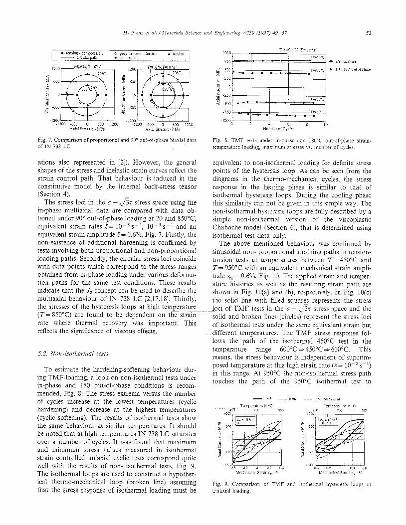
Fig. 7. Comparison of proportional and 90” out-of-phase biaxial data Fig. 8. TMF tests under in-phase and 180°C out-of-phase strain- of IN 738 LC. temperature loading, maximum stresses vs. number of cycles.
ations also represented in [2]). However, the general shapes of the stress and inelastic strain curves reflect the strain control path. That behaviour is induced in the constitutive model by the internal back-stress tensor (Section 4).
The stress loci in the G-J’& stress space using the in-phase multiaxial data are compared with data ob- tained under 90” out-of-phase loading at 20 and 850°C equivalent strain rates i= 10m3 s-l, 10B5 s-i and an equivalent strain amplitude E= 0.6%, Fig. 7. Firstly, the non-existence of additional hardening is confirmed by tests involving both proportional and non-proportional loading paths. Secondly, the circular stress loci coincide with data points which correspond to the stress ranges obtained from in-phase loading under various deforma- tion paths for the same test conditions. These results indicate that the J,-concept can be used to describe the multiaxial behaviour of IN 738 LC [2,17,18]. Thirdly, the stresses of the hysteresis loops at high temperature (T= SSO’C) are found to be dependent on the strain rate where thermal recovery was important. This reflects the significance of viscous effects.
5.2. Non-isothemnl tests
To estimate the hardening-softening behaviour dur- ing TMF-loading, a look on non-isothermal tests under in-phase and 180 out-of-phase conditions is recom- mended, Fig. 8. The stress extrema versus the number of cycles increase at the lowest temperatures (cyclic hardening) and decrease at the highest temperatures (cyclic softening). The results of isothermal tests show the same behaviour at similar temperatures. It should be noted that at high temperatures IN 738 LC saturates over a number of cycles. It was found that maximum and minimum stress values measured in isothermal strain controlled uniaxial cyclic tests correspond quite well with the results of non- isothermal tests, Fig. 9. The isothermal loops are used to construct a hypothet- ical thermo-mechanical loop (broken line) assuming that the stress response of isothermal loading must be
1000 ~z*o$ y. E= lo”s”
750 l = ,= = (0 = /= = ,*
1 T=450°C -a- E/T InPhase
z -250 3 T=950°C 4 -500 - - - = ; = = l
-750 m T=450°C.
-1000 -i - -I ‘, =’ 0 2 4 6 8 10
Number of Cycles
equivalent to non-isothermal loading for definite stress points of the hysteresis loop. As can be seen from the diagrams in the thermo-mechanical cycles, the stress response in the heating phase is similar to that of isothermal hysteresis loops. During the cooling phase this similarity can not be given in this simple way. The non-isothermal hysteresis loops are fully described by a simple non-isothermal version of the viscoplastic Chaboche model (Section 6), that is determined using isothemlal test data only.
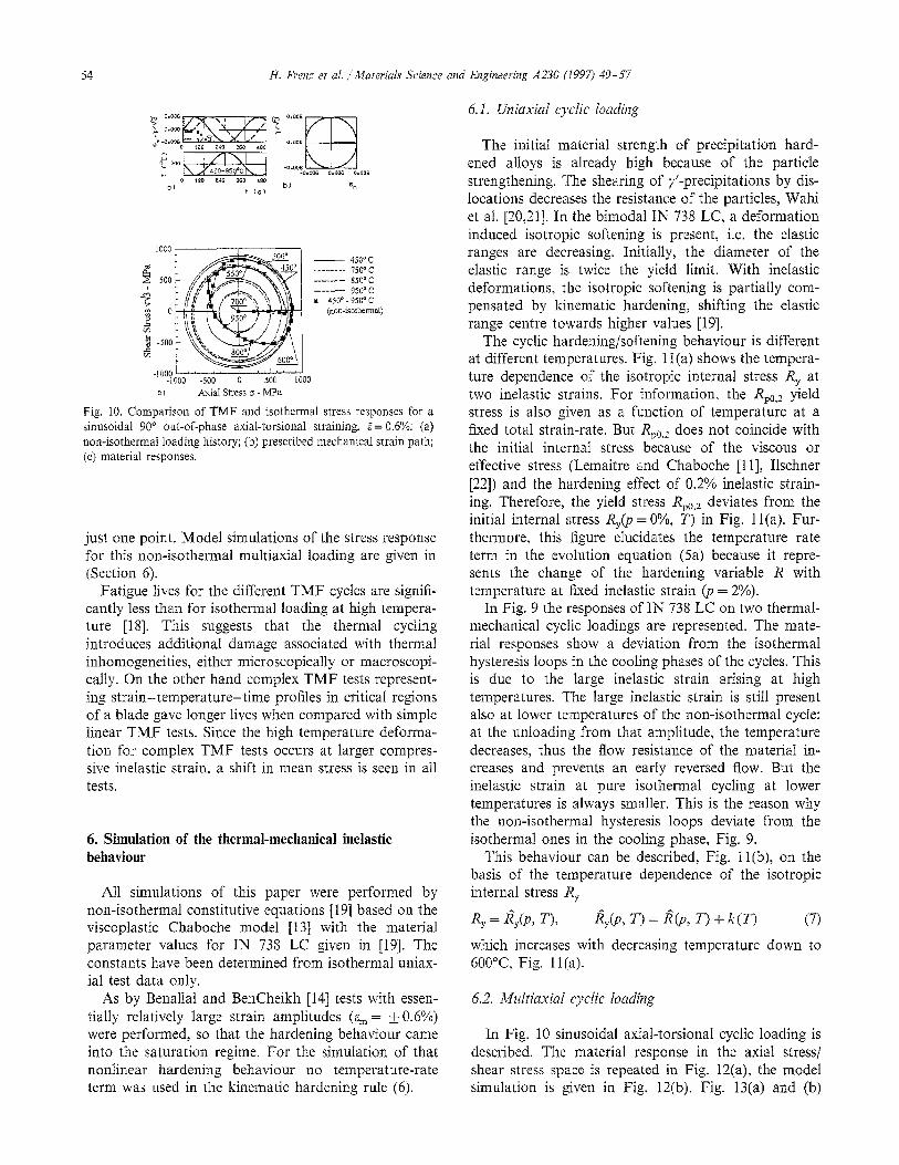
The above mentioned behaviour was confirmed by sinusoidal non- proportional straining paths in tension- torsion tests at temperatures between T= 450°C and T= 950°C with an equivalent mechanical strain ampli- tude & = 0.6%, Fig. 10. The applied strain and temper- ature histories as well as the resulting strain path are shown in Fig. 10(a) and (b), respectively. In Fig. IO(c) the solid line with filled squares represents the stress loci of TMF tests in the G - 37 stress space and the solid and broken lines (circles) represent the stress loci of isothermal tests under the same equivalent strain but different temperatures. The TMF stress response fol- lows the path of the isothermal 450°C test in the temperature range 600°C * 450°C * 600°C. This means, the stress behaviour is independent of superim- posed temperature at this high strain rate (i = 10M3 s-l) in this range. At 950°C the non-isothermal stress path touches the path of the 950°C isothermal test in
Mechamcal Strain E, - %
Fig. 9. Comparison of TMF and isothermal hysteresis loops at uniaxial loading.
54 H. Frenz et al. /‘Materials Science and Engineering A230 (1997) 49-57
- 450ac ______-. 75ooc ---- 8SO’C -__--. 9gyc . 450”. 95O’C
(non-mhemwl)
C) Axial Stress cs - MPa
Fig. 10. Comparison of TMF and isothermal stress responses for a sinusoidal 90” out-of-phase axial-torsional straining, B= 0.60/o: (a) non-isothermal loading history; (b) prescribed mechanical strain path; (cj material responses.
just one point. Model simulations of the stress response for this non-isothermal multiaxial loading are given in (Section 6).
Fatigue lives for the different TMF cycles are signifi- cantly less than for isothermal loading at high tempera- ture [18]. This suggests that the thermal cycling introduces additional damage associated with thermal inhomogeneities, either microscopically or macroscopi- tally. On the other hand complex TMF tests represent- ing strain-temperature-time profiles in critical regions of a blade gave longer lives when compared with simple linear TMF tests. Since the high temperature deforma- tion for complex TMF tests occurs at larger compres- sive inelastic strain, a shift in mean stress is seen in all tests.
6. Simulation of the thermal-mechanical inelastic behaviour
All simulations of this paper were performed by non-isothermal constitutive equations [19] based on the viscoplastic Chaboche model [13] with the material parameter values for IN 738 LC given in [19]. The constants have been determined from isothermal uniax- ial test data only.
As by Benallal and BenCheikh [14] tests with essen- tially relatively large strain amplitudes (E, = i 0.6%) were performed, so that the hardening behaviour came into the saturation regime. For the simulation of that nonlinear hardening behaviour no temperature-rate term was used in the kinematic hardening rule (6).
6.1. Uniaxial cyclic loading
The initial material strength of precipitation hard- ened alloys is already high because of the particle strengthening. The shearing of y’-precipitations by dis- locations decreases the resistance of the particles, Wahi et al. [20:21]. In the bimodal IN 738 LC, a deformation induced isotropic softening is present, i.e. the elastic ranges are decreasing. Initially, the diameter of the elastic range is twice the yield limit. With inelastic deformations, the isotropic softening is partially com- pensated by kinematic hardening, shifting the elastic range centre towards higher values [19].
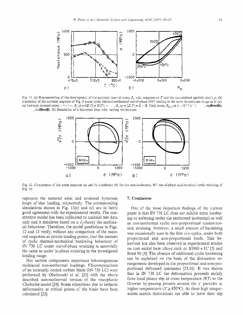
The cyclic hardening/softening behaviour is different at different temperatures. Fig. 1 l(a) shows the tempera- ture dependence of the isotropic internal stress R, at two inelastic strains. For information, the Rp0,2 yield stress is also given as a function of temperature at a fixed total strain-rate. But Rp,,2 does not coincide with the initial internal stress because of the viscous or effective stress (Lemaitre and Chaboche [l 11, Ilschner [22]) and the hardening effect of 0.2% inelastic strain- ing. Therefore, the yield stress Rp0,2 deviates from the initial internal stress R&p = O%, T) in Fig. 1 l(a). Fur- thermore, this figure elucidates the temperature rate term in the evolution equation (5a) because it repre- sents the change of the hardening variable R with temperature at fixed inelastic strain (p = 2%).
In Fig. 9 the responses of IN 738 LC on two thermal- mechanical cyclic loadings are represented. The mate- rial responses show a deviation from the isothermal hysteresis loops in the cooling phases of the cycles. This is due to the large inelastic strain arising at high temperatures. The large inelastic strain is still present also at lower te:mperatures of the non-isothermal cycle: at the unloading from that amplitude, the temperature decreases: thus the flow resistance of the material in- creases and prevents an early reversed flow. But the inelastic strain at pure isothermal cycling at lower temperatures is always smaller. This is the reason why the non-isothermal hysteresis loops deviate from the isothermal ones in the cooling phase, Fig. 9.
This behaviour can be described, Fig. 1 l(b), on the basis of the temperature dependence of the isotropic internal stress R,
R, = fi&, T), i,(p, T) = I&, T) + k(T) (7)
which increases with decreasing temperature down to 600°C. Fig. 11(a).
6.2. Multiaxia~ cyclic loahg
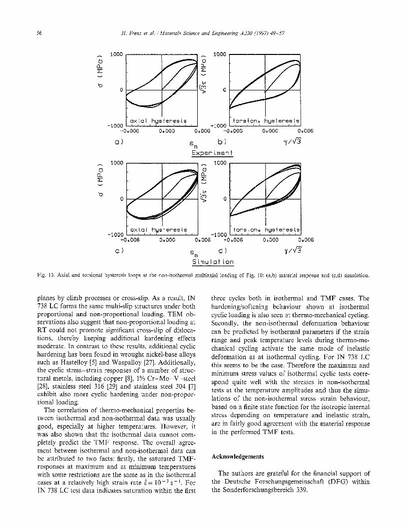
In Fig. 10 sinusoidal axial-torsional cyclic loading is described. The material response in the axial stress/ shear stress space is repeated in Fig. 12(a), the model simulation is given in Fig. 12(b). Fig. 13(a) and (b)
H. Frenz et al. /Materials Science and Engineering A230 (1997) 49-57
b
475.0 71205 950.0 -0.006 0.000 0.006
Cl) T (‘C) b)
Fig. 11. (a) Representation of the development of the isotropic internal stress R, with temperature T and the accumulated inelastic strain p; (b) simulation of the material response of Fig. 9 under cyclic thermal-mechanical out-of-phase (OP) loading in the same temperature range as in (a). (a) Isotropic internal stress: - 2 - * -, R,(p=OZ,T)=K(T);---,R,~=2Z.T)=K+R.Yieldslress,R~,,,at~=lO-j~-’: ,ex$rimk%ht;
, siM. (b) Simulation of a hysteresis loop with varying temperature.
Cl) d (MPa) b) d (MPa)
Fig. 12. Comparison of the stress response (a) and its simulation (b) for the non-isothermal, 90” out-of-phase axial-torsional cyclic straining of Fig. 10.
represent the material axial and torsional hysteresis loops of that loading, respectively. The corresponding simulations shown in Fig. 13(c) and (d) are in fairly good agreement with the experimental results. The con- stitutive model has been calibrated to uniaxial test data only and it simulates based on a J,-theory the multiax- ial behaviour. Therefore, the model predictions in Figs. 12 and 13 verify, without any comparison of the mate- rial responses at certain loading points, that the amount of cyclic thermal-mechanical hardening behaviour of IN 738 LC under out-of-phase straining is essentially the same as under in-phase straining in the investigated loading range.
Hot section components experience inhomogeneous multiaxial non-isothermal loadings. FE-computations of an internally cooled turbine blade (IN 738 LC) were performed by Olschewski et al. [23] with the above described non-isothermal version of the viscoplastic Chaboche model [24]. Stress relaxations due to inelastic deformation at critical points of the blade have been calculated [23].
7. Conclusions
One of the most important findings of the current paper is that IN 738 LC does not exhibit extra harden- ing or softening under the performed isothermal as well as non-isothermal cyclic non-proportional tension/tor- sion straining. However, a small amount of hardening was occasionally seen in the first two cycles, under both proportional and non-proportional loads. This be- haviour has also been observed in experimental studies on cast nickel base alloys such as B1900 + Hf [3] and Renk 80 [4]. The absence of additional cyclic hardening can be explained on the basis of the dislocation ar- rangements developed in the proportional and non-pro- portional deformed specimens [25,26]. It was shown that in IN 738 LC the deformation proceeds mainly from local planar slip at room temperature (RT) to the Orowan by-passing process around the y’ particles at higher temperatures (T> SSO’C). At these high temper- atures matrix dislocations are able to leave their slip
H. Frenz et al. /‘Materials Science and Engineering A230 (1997) 49-57
-1000 -0.006
Cl)
torsiona -1000 3 t
hysteresis 8
0.000 0.006 -0.006 0.000 0.006
%l b) y/lJs
Exper imen t
-1000 -0.006
cl
-1000 0.000 0.006 -0.006 0.000 0.006
Eln d) +&3
Simulation
Fig. 13. Axial and torsional hysteresis loops at the non-isothermal multiaxiai loading of Fig. 10: (a,b) material response and (c,d) simulation.
planes by climb processes or cross-slip. As a result, IN 738 LC forms the same multi-slip structures under both proportional and non-proportional loading. TEM ob- servations also suggest that non-proportional loading at RT could not promote significant cross-slip of disloca- tions, thereby keeping additional hardening effects moderate. In contrast to these results, additional cyclic hardening has been found in wrought nickel-base alloys such as Hastelloy [S] and Waspalloy [27]. Additionally, the cyclic stress-strain responses of a number of struc- tural metals, including copper [8], 1% Cr-MO-V-steel [28], stainless steel 316 [29] and stainless steel 304 [7] exhibit also more cyclic hardening under non-propor- tional loading.
The correlation of thermo-mechanical properties be- tween isothermal and non-isothermal data was usually good, especially at higher temperatures. However, it was also shown that the isothermal data cannot com- pletely predict the TMF response. The overall agree- ment between isothermal and non-isothermal data can be attributed to two facts: firstly, the saturated TMF- responses at maximum and at minimum temperatures with some restrictions are the same as in the isothermal cases at a relatively high strain rate i = 10 -3 s - I. For IN 738 LC test data indicates saturation within the first
three cycles both in isothermal and TMF cases. The hardening/softening behaviour shown at isothermal cyclic loading is also seen at thermo-mechanical cycling. Secondly, the non-isothermal deformation behaviour can be predicted by isothermal parameters if the strain range and peak temperature levels during thermo-me- chanical cycling activate the same mode of inelastic deformation as at isothermal cycling. For IN 738 LC this seems to be the case. Therefore the maximum and minimum stress values of isothermal cyclic tests corre- spond quite well with the stresses in non-isothermal tests at the temperature amplitudes and thus the simu- lations of the non-isothermal stress-strain behaviour, based on a finite state function for the isotropic internal stress depending on temperature and inelastic strain, are in fairly good agreement with the material response in the performed TMF tests.
Acknowledgements
The authors are grateful for the &nancial support of the Deutsche Forschungsgemeinschaft (DFG) within the Sonderforschungsbereich 339.
H. Ren: et al. /Materials Science and Engineering AZ30 (1997) 49-57 57
References
[l] G.T. Embley and ES. Russel, in First Parsons Int. lilrbine ConfereTrce, Inst. Mechanical Engineers, London, Parsons Press, Trinity College, Dublin, 1984, p. 157
[2] J. Ziebs, J. Meersmann and H.-J. Kuhn, Elrr. J. iMe&, A/Solids, 13 (5) (1994) 605.
[3] KS. Chan, US. Lindholm, S.R. Bodner and A. Nagy, J. Engng. Mat. Techn., 112 (1990) 7.
[4] D.C. Stouffer, V.G. Ramaswamy, J.H. L&n, R.H. Van Stone and R. Williams, J. Eng. Muter. Techn., 112 (1990) 241.
[5] U.S. Lindholm, in V. Weiss and W.T. Bakker (eds.), Proc. Conf Life Prodiction for High-Temperature Gas Turbine Materials, Syracuse University, 1985, p. 7-l.
[6] D. Bettge, W. esterle and J. Ziebs, Ser. Metall. Mater., 32 (1995) 1601.
[7] D.L. McDowell, D.R. Stahl, S.R. Stock and SD. Antolovich, Met. Trans. A, 19A (1988) 1271.
[S] H.S. Lamba and O.M. Sidebottom, J. Eng. Maw. Tech., 100 (1978) 96.
[9] C.J. Franklin, in D. Coutsouradis et al. (eds.), High Temperawe Alloys For Gas Turbines, Applied Science, London, 1978, p. 513.
[lo] R. Sievert, J. Meersmann, H.-J. Kuhn, M. Bendig, H. Frenz, J. Olschewski and J. Ziebs, in G. Ltitjering and H. Nowack (eds.), Fatigue’Y6, Vol. II, Pergamon, Elsevier Science, 1996, p. 837.
11 l] J. Lemaitre and J.-L. Chaboche, Mechanics of Solid Muterials, Cambridge University Press, UK, 1990.
1121 P. Gem-rain, Q.S. Nguyen and P. Suquet, J. Appl. Mechanics, 50 (1983) 1010.
:I 3J J.-L. Chaboche, EuIIetin de L ‘Acadetnie des Sciemes XXV, Serie des Sciences Techniques, 1977, p. 33.
1141 A. Benallal and A. Ben Cheikh, in C.S. Desai et al. (eds.), Constittrtive Laws for Engineering Materials, ASME Press, New York, 1987, p, 667.
1151 J.-D. Wang and N. Ohno, Int. J. Plasticity, 7 (1991) 637. :16] J. Ziebs, J. Meersmann and H.-J. Kuhn, in K.T. Rie (ed.), Low
Cycle Fatigue and Elastic-Plastic Behaviour of Materials, Vol. 3, Elsevier Applied Science, London, 1992, p. 248.
[17] J. Olschewski, R. Sievert and A. Bertram. in C.S. Desai et al. (eds.), Constitutite Laws for Engineering Materials, ASME Press, New York, 1991, p. 755.
[18] J. Meersmann, J. Ziebs, H.-J. Kuhn, R. Sievert, J. Olschewski and H. Frenz, in J. Bressers and L. Remy (eds.), Fatigue Under Thermal and Mechanical Loading-Mechanisms, Mechanics and Modelling, Kluwer Academic, Dordrecht, 1996, p, 425.
[19] J. Olschewski, R. Sievert, W. Qi and A. Bertram, in K. Kuss- maul (ed.), Trans. 12th Int. Conf. on Structural Mechanics in Reactor Technology (SMiRT-12), Vol. L, Elsevier Science, Am- sterdam, 1993, p. 17.
1201 R.P. Wahi, W. Chen, V. Singh and V.V. Kutumbarao, Z. Metah’kd., 83 (1992) 144.
[21] F. Jiao, W. Chen, D. Mukherji, J. Zhu and R.P. Wahi, in M. Jono and T. Inoue (eds.), Mechanical Behaviottr of Materials, Vol. VI, Proc. ICM6, Pergamon Press, Oxford, 1992, p. 385.
[22] B. Ilschner, Hochremperatur-Plastizitiit, Springer Verlag, Berlin, 1973.
[23] J. Olschewski, C. Haftaoglu and H.-D. Noack, in G. Liitjering and H. Nowack (eds.), Fatigue’96, Vol. II, Pergamon, Elsevier Science, 1996, p. 1123.
[24] S. Beckmoller, J. Wolters, G. Breitbach, H.J. Penkalla and F. Schubert, in D. Coutsouradis et al. (eds.), Materials for Ad- vanced Power Engineering, Part I, Kluwer Academic, Dordrecht, 1994, p. 829.
1251 S.-H. Doong, D.F. Socie and I.M. Robertson, J. Eng. Marer. Tech., 112 (1990) 457.
[26] M. Clavel and X. Flangas, in A. Pineau, G. Cailletaud and T.C. Lindley (eds.), Multiaxial Fatigue and Design, ESIS-P. 21, Mech. Eng., London, 1996, p. 21.
1271 G. Cailletaud, V. Doquet and A. Pineau, in K. Kussmaul, D. McDarmid and D. Socie (eds.), Fatigue under Biaxial and Multi- axial Loading, ESTS-P. 10, Mech. Eng., London, 1991, p. 131.
[28] K. Kanazawa, K.J. Miller and M.W. Brown, Far. Eng. Marer. Struct., 2 (1979) 217.
1291 E. Tanaka, S. Marukami and M. Doka, J. Mech. Phys. Solids, 33 (1985) 559.