high pressure gear pumps kp 2/ kp 3 -...
TRANSCRIPT
High Pressure Gear Pumps
KP 2 / KP 3
2 KRACHT GmbH · Gewerbestr. 20 · 58791 Werdohl, Germany · Phone +49 23 92.935-0 · Fax +49 23 92.935 209 · Email [email protected] · Web www.kracht.eu
High Pressure Gear Pumps KP2 /KP3
3KRACHT GmbH · Gewerbestr. 20 · 58791 Werdohl, Germany · Phone +49 23 92.935-0 · Fax +49 23 92.935 209 · Email [email protected] · Web www.kracht.eu
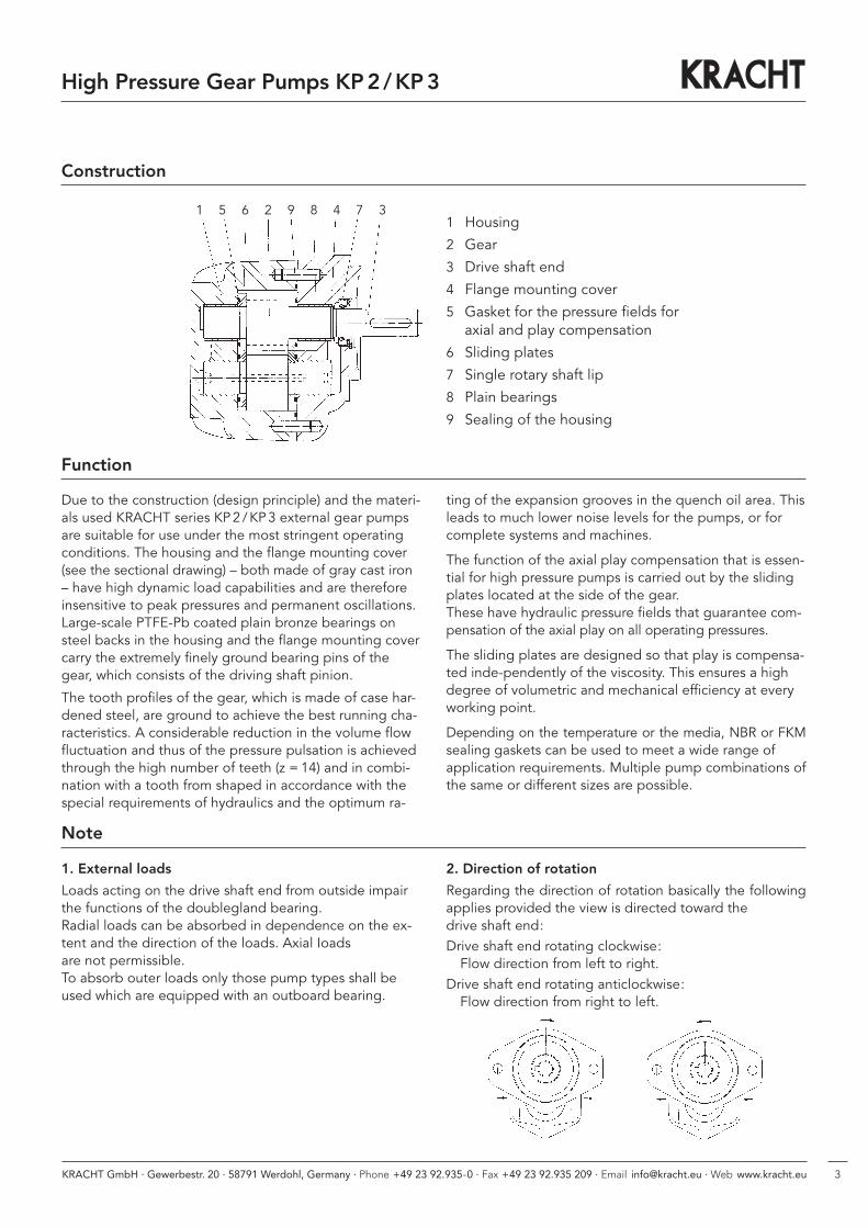
1 Housing
2 Gear
3 Drive shaft end
4 Flange mounting cover
5 Gasket for the pressure fields foraxial and play compensation
6 Sliding plates
7 Single rotary shaft lip
8 Plain bearings
9 Sealing of the housing
Due to the construction (design principle) and the materi-als used KRACHT series KP2 /KP3 external gear pumpsare suitable for use under the most stringent operatingconditions. The housing and the flange mounting cover(see the sectional drawing) – both made of gray cast iron – have high dynamic load capabilities and are thereforeinsensitive to peak pressures and permanent oscillations.Large-scale PTFE-Pb coated plain bronze bearings onsteel backs in the housing and the flange mounting covercarry the extremely finely ground bearing pins of thegear, which consists of the driving shaft pinion.
The tooth profiles of the gear, which is made of case har-dened steel, are ground to achieve the best running cha-racteristics. A considerable reduction in the volume flowfluctuation and thus of the pressure pulsation is achievedthrough the high number of teeth (z = 14) and in combi-nation with a tooth from shaped in accordance with thespecial requirements of hydraulics and the optimum ra-
Function
Construction
ting of the expansion grooves in the quench oil area. Thisleads to much lower noise levels for the pumps, or forcomplete systems and machines.
The function of the axial play compensation that is essen-tial for high pressure pumps is carried out by the slidingplates located at the side of the gear. These have hydraulic pressure fields that guarantee com- pensation of the axial play on all operating pressures.
The sliding plates are designed so that play is compensa-ted inde-pendently of the viscosity. This ensures a highdegree of volumetric and mechanical efficiency at everyworking point.
Depending on the temperature or the media, NBR or FKMsealing gaskets can be used to meet a wide range of application requirements. Multiple pump combinations ofthe same or different sizes are possible.
1 5 6 2 9 8 4 7 3
High Pressure Gear Pumps KP2 /KP3
Note
1. External loads
Loads acting on the drive shaft end from outside impairthe functions of the doublegland bearing.Radial loads can be absorbed in dependence on the ex-tent and the direction of the loads. Axial Ioads are not permissible.To absorb outer loads only those pump types shall beused which are equipped with an outboard bearing.
2. Direction of rotation
Regarding the direction of rotation basically the followingapplies provided the view is directed toward the drive shaft end:Drive shaft end rotating clockwise: Flow direction from left to right.
Drive shaft end rotating anticlockwise:Flow direction from right to left.
4 KRACHT GmbH · Gewerbestr. 20 · 58791 Werdohl, Germany · Phone +49 23 92.935-0 · Fax +49 23 92.935 209 · Email [email protected] · Web www.kracht.eu
High Pressure Gear Pumps KP2 /KP3
Materials
Housing grey cast iron
Bearing composite plain bearing bushes
Journals and gears case hardening steel acc. to DIN 17210surface hardened and ground
Seals NBR rotary shaft lip type sealϑ � 90 °CFKM rotary shaft lip type sealϑ � 150 °C
Characteristics
Mounting flange type
Pipe connection flange
Direction of rotation clockwise or anticlockwise
Weight see dimension sheets
Mounting position optional
Ambient temperature ϑu min = – 20 °Cϑu max = 60 °C
Operating pressure Inlet port pe min = – 0.4 bar (vacuum)pe max = 2 bar
Operating pressure Short time pe max = 5 bar
Operating pressure Outlet port pe max = 300 bar
Fluid temperature range ϑm max 90 °C for NBR rotary shaft lip type sealϑm max 150 °C for FKM rotary shaft lip type seal
Viscosity νmin = 10 mm2/sνmax = 600 mm2/s
Recommended oil cleanliness according to ISO 4406 : 1999 Code 21/19/16� according to NAS 1638 Class 10
Recommended filtration filter with filtration quotientβ25 � 75 for … 300 barβ40 � 75 for … 100 bar
Recommended viscosity range ν = 30…45 mm2/s
Discharge flow see chart page 7 and 8
Input power see chart page 7 and 8
Hydraulic fluids mineral oil acc. to DIN 51524/25engine oil acc. to DIN 51511flame-retardant hydraulic fluids on requestbio-oils of typ „HEES“, can be used up to 70 °C, max. pressure must be reduced minus 20%(use only on request)
ATEX (KP2 only) Products and media on request.

5KRACHT GmbH · Gewerbestr. 20 · 58791 Werdohl, Germany · Phone +49 23 92.935-0 · Fax +49 23 92.935 209 · Email [email protected] · Web www.kracht.eu
Characteristic data, formula signs, units
Discharge flow / input flow Q l/min
Pump /motor displacement Vg cm3/r
Pressure p bar
Speed of rotation n 1/min
Torque M Nm
Power P kW
Total efficiency η tot –
Volumetric efficiency η vol –
Hydr./mech. efficiency ηhm –
Flow velocity v m/s
Pipe diameter d mm
General
Qth = Vg · n, η tot = η vol · ηhm
M = 9549 · v = 21.22 ·Qd2
Pn
High Pressure Gear Pumps KP2 /KP3
Calculation Formulas for Hydraulic Pumps
Approximate values for KRACHT products in the nominal operating point
ηtot ηvol
KP � 0.90 � 0.95
Characteristic data for:
Power
Torque
Volumetric
flow Discharge flow Q =
Vg · n · ηvol103
lmin
Drive torque M =p · Vg
20 · π · ηhm[Nm]
Input power P =p · Q
600 · ηtot[kW]
Q
p
nMP
Pump
KRACHT GmbH · Gewerbestr. 20 · 58791 Werdohl, Germany · Phone +49 23 92.935-0 · Fax +49 23 92.935 209 · Email [email protected] · Web www.kracht.eu6
High Pressure Gear Pumps KP2 /KP3
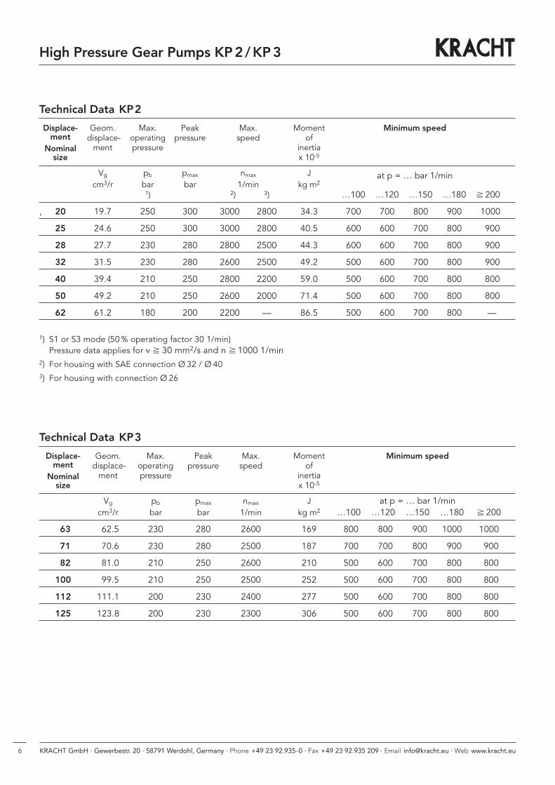
Technical Data KP2
Displace- Geom. Max. Peak Max. Moment Minimum speedment displace- operating pressure speed of
Nominal ment pressure inertiasize x 10-5
Vg pb pmax nmax J at p = … bar 1/mincm3/r bar bar 1/min kg m2
1) 2) 3) …100 …120 …150 …180 � 200
, 20 19.7 250 300 3000 2800 34.3 700 700 800 900 1000
25 24.6 250 300 3000 2800 40.5 600 600 700 800 900
28 27.7 230 280 2800 2500 44.3 600 600 700 800 900
32 31.5 230 280 2600 2500 49.2 500 600 700 800 900
40 39.4 210 250 2800 2200 59.0 500 600 700 800 800
50 49.2 210 250 2600 2000 71.4 500 600 700 800 800
62 61.2 180 200 2200 — 86.5 500 600 700 800 —
1) S1 or S3 mode (50% operating factor 30 1/min) Pressure data applies for ν � 30 mm2/s and n � 1000 1/min
2) For housing with SAE connection Ø 32 / Ø 403) For housing with connection Ø 26
Technical Data KP3
Displace- Geom. Max. Peak Max. Moment Minimum speedment displace- operating pressure speed of
Nominal ment pressure inertiasize x 10-5
Vg pb pmax nmax J at p = … bar 1/mincm3/r bar bar 1/min kg m2 …100 …120 …150 …180 � 200
63 62.5 230 280 2600 169 800 800 900 1000 1000
71 70.6 230 280 2500 187 700 700 800 900 900
82 81.0 210 250 2600 210 500 600 700 800 800
100 99.5 210 250 2500 252 500 600 700 800 800
112 111.1 200 230 2400 277 500 600 700 800 800
125 123.8 200 230 2300 306 500 600 700 800 800
7KRACHT GmbH · Gewerbestr. 20 · 58791 Werdohl, Germany · Phone +49 23 92.935-0 · Fax +49 23 92.935 209 · Email [email protected] · Web www.kracht.eu
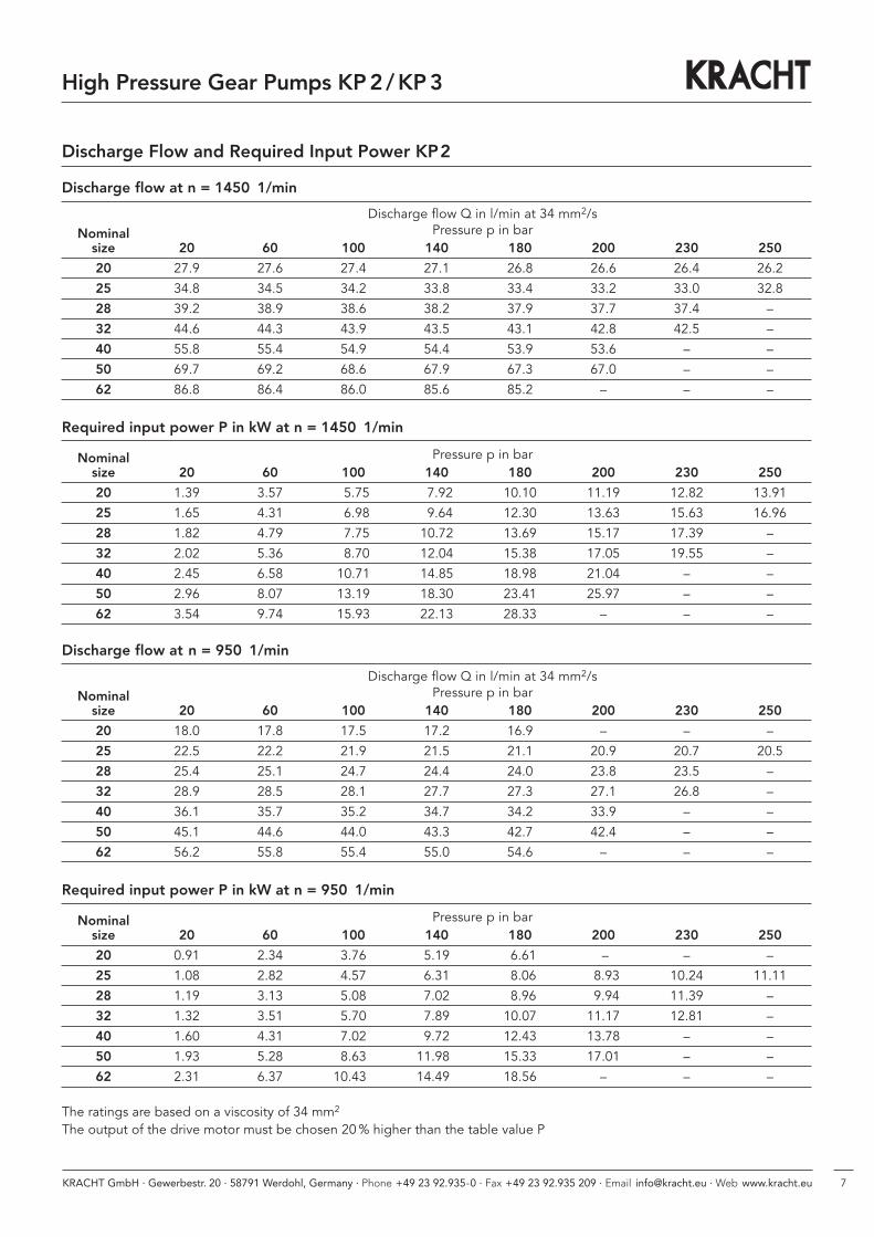
Discharge flow Q in l/min at 34 mm2/sNominal Pressure p in bar
size 20 60 100 140 180 200 230 250
20 27.9 27.6 27.4 27.1 26.8 26.6 26.4 26.2
25 34.8 34.5 34.2 33.8 33.4 33.2 33.0 32.8
28 39.2 38.9 38.6 38.2 37.9 37.7 37.4 –
32 44.6 44.3 43.9 43.5 43.1 42.8 42.5 –
40 55.8 55.4 54.9 54.4 53.9 53.6 – –
50 69.7 69.2 68.6 67.9 67.3 67.0 – –
62 86.8 86.4 86.0 85.6 85.2 – – –
Discharge flow at n = 1450 1/min
Discharge Flow and Required Input Power KP2
Nominal Pressure p in barsize 20 60 100 140 180 200 230 250
20 1.39 3.57 5.75 7.92 10.10 11.19 12.82 13.91
25 1.65 4.31 6.98 9.64 12.30 13.63 15.63 16.96
28 1.82 4.79 7.75 10.72 13.69 15.17 17.39 –
32 2.02 5.36 8.70 12.04 15.38 17.05 19.55 –
40 2.45 6.58 10.71 14.85 18.98 21.04 – –
50 2.96 8.07 13.19 18.30 23.41 25.97 – –
62 3.54 9.74 15.93 22.13 28.33 – – –
Required input power P in kW at n = 1450 1/min
Discharge flow Q in l/min at 34 mm2/sNominal Pressure p in bar
size 20 60 100 140 180 200 230 250
20 18.0 17.8 17.5 17.2 16.9 – – –
25 22.5 22.2 21.9 21.5 21.1 20.9 20.7 20.5
28 25.4 25.1 24.7 24.4 24.0 23.8 23.5 –
32 28.9 28.5 28.1 27.7 27.3 27.1 26.8 –
40 36.1 35.7 35.2 34.7 34.2 33.9 – –
50 45.1 44.6 44.0 43.3 42.7 42.4 – –
62 56.2 55.8 55.4 55.0 54.6 – – –
Discharge flow at n = 950 1/min
Nominal Pressure p in barsize 20 60 100 140 180 200 230 250
20 0.91 2.34 3.76 5.19 6.61 – – –
25 1.08 2.82 4.57 6.31 8.06 8.93 10.24 11.11
28 1.19 3.13 5.08 7.02 8.96 9.94 11.39 –
32 1.32 3.51 5.70 7.89 10.07 11.17 12.81 –
40 1.60 4.31 7.02 9.72 12.43 13.78 – –
50 1.93 5.28 8.63 11.980 15.33 17.01 – –
62 2.31 6.37 10.430 14.490 18.56 – – –
Required input power P in kW at n = 950 1/min
The ratings are based on a viscosity of 34 mm2
The output of the drive motor must be chosen 20% higher than the table value P
High Pressure Gear Pumps KP2 /KP3
8 KRACHT GmbH · Gewerbestr. 20 · 58791 Werdohl, Germany · Phone +49 23 92.935-0 · Fax +49 23 92.935 209 · Email [email protected] · Web www.kracht.eu
High Pressure Gear Pumps KP2 /KP3
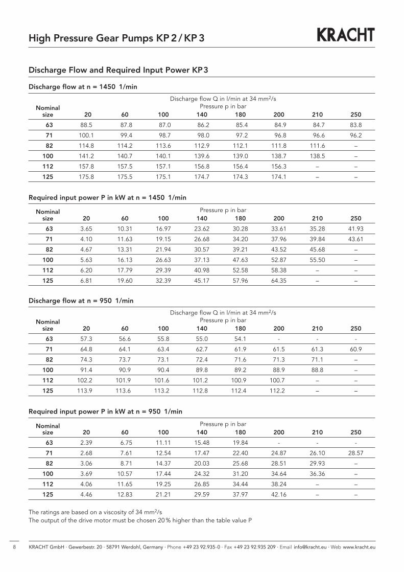
Discharge Flow and Required Input Power KP3
Discharge flow Q in l/min at 34 mm2/sNominal Pressure p in bar
size 20 60 100 140 180 200 210 250
63 88.5 87.8 87.0 86.2 85.4 84.9 84.7 83.8
71 100.1 99.4 98.7 98.0 97.2 96.8 96.6 96.2
82 114.8 114.2 113.6 112.9 112.1 111.8 111.6 –
100 141.2 140.7 140.1 139.6 139.0 138.7 138.5 –
112 157.8 157.5 157.1 156.8 156.4 156.3 – –
125 175.8 175.5 175.1 174.7 174.3 174.1 – –
Discharge flow at n = 1450 1/min
Nominal Pressure p in barsize 20 60 100 140 180 200 210 250
63 3.65 10.31 16.97 23.62 30.28 33.61 35.28 41.93
71 4.10 11.63 19.15 26.68 34.20 37.96 39.84 43.61
82 4.67 13.31 21.94 30.57 39.21 43.52 45.68 –
100 5.63 16.13 26.63 37.13 47.63 52.87 55.50 –
112 6.20 17.79 29.39 40.98 52.58 58.38 – –
125 6.81 19.60 32.39 45.17 57.96 64.35 – –
Required input power P in kW at n = 1450 1/min
Discharge flow Q in l/min at 34 mm2/sNominal Pressure p in bar
size 20 60 100 140 180 200 210 250
63 57.3 56.6 55.8 55.0 54.1 - - -
71 64.8 64.1 63.4 62.7 61.9 61.5 61.3 60.9
82 74.3 73.7 73.1 72.4 71.6 71.3 71.1 –
100 91.4 90.9 90.4 89.8 89.2 88.9 88.8 –
112 102.20 101.90 101.60 101.20 100.90 100.70 – –
125 113.90 113.60 113.20 112.80 112.40 112.20 – –
Discharge flow at n = 950 1/min
Nominal Pressure p in barsize 20 60 100 140 180 200 210 250
63 2.39 6.75 11.11 15.48 19.84 - - -
71 2.68 7.61 12.54 17.47 22.40 24.87 26.10 28.57
82 3.06 8.71 14.37 20.03 25.68 28.51 29.93 –
100 3.69 10.57 17.44 24.32 31.20 34.64 36.36 –
112 4.06 11.65 19.25 26.85 34.44 38.24 – –
125 4.46 12.83 21.21 29.59 37.97 42.16 – –
Required input power P in kW at n = 950 1/min
The ratings are based on a viscosity of 34 mm2/sThe output of the drive motor must be chosen 20% higher than the table value P
9KRACHT GmbH · Gewerbestr. 20 · 58791 Werdohl, Germany · Phone +49 23 92.935-0 · Fax +49 23 92.935 209 · Email [email protected] · Web www.kracht.eu
High Pressure Gear Pumps KP2 /KP3
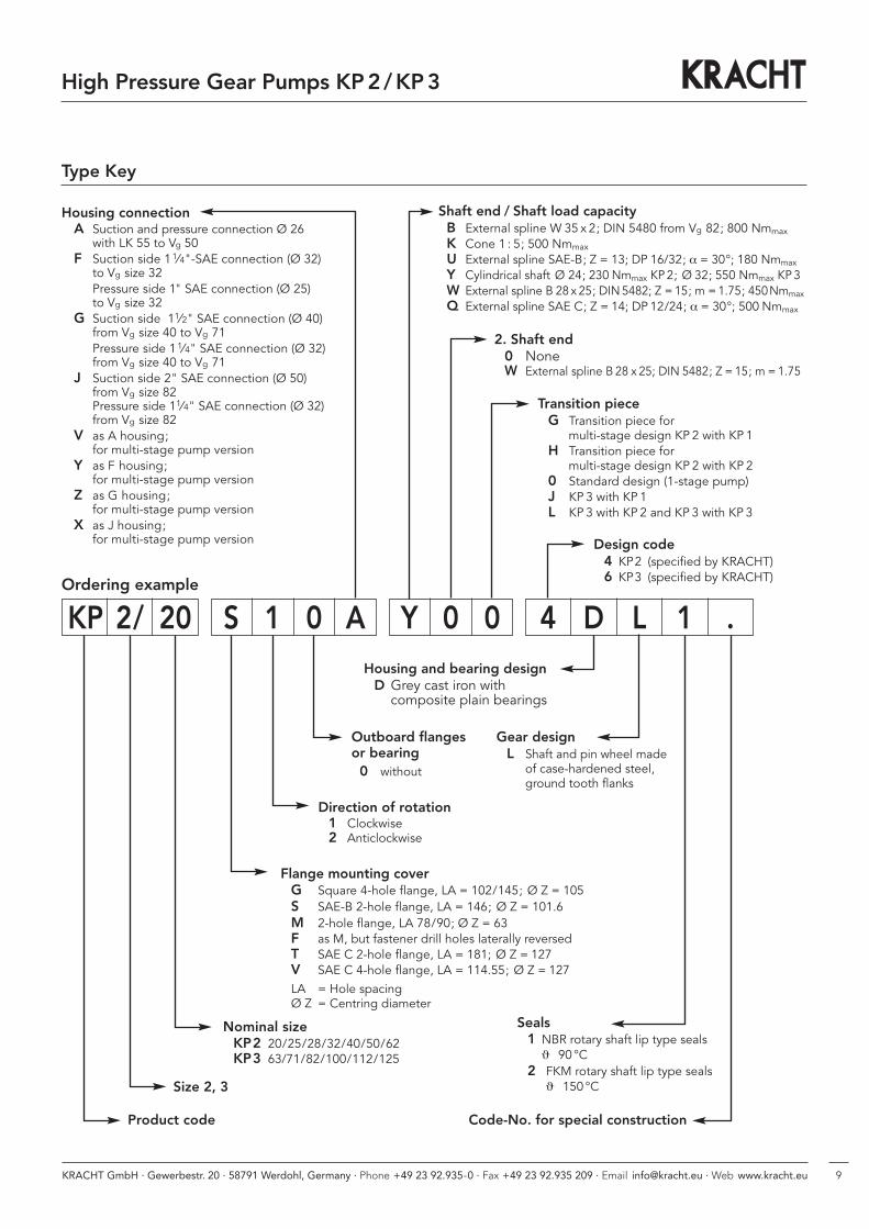
Type Key
Ordering example
Seals 1 NBR rotary shaft lip type seals
ϑ � 90 °C2 FKM rotary shaft lip type seals
ϑ � 150 °CSize 2, 3
Product code
Nominal sizeKP2 20/25/28/32/40/50/62KP3 63/71/82/100/112/125
Flange mounting coverG Square 4-hole flange, LA = 102/145; Ø Z = 105S SAE-B 2-hole flange, LA = 146; Ø Z = 101.6M 2-hole flange, LA 78/90; Ø Z = 63F as M, but fastener drill holes laterally reversedT SAE C 2-hole flange, LA = 181; Ø Z = 127V SAE C 4-hole flange, LA = 114.55; Ø Z = 127LA = Hole spacingØ Z = Centring diameter
Direction of rotation1 Clockwise2 Anticlockwise
Outboard flangesor bearing0 without
Code-No. for special construction
Shaft end / Shaft load capacityB External spline W 35 x 2; DIN 5480 from Vg 82; 800 Nmmax
K Cone 1 : 5; 500 Nmmax
U External spline SAE-B; Z = 13; DP 16/32; α = 30°; 180 Nmmax
Y Cylindrical shaft Ø 24; 230 Nmmax KP2; Ø 32; 550 Nmmax KP3W External spline B 28 x 25; DIN5482; Z = 15; m = 1.75; 450Nmmax
Q External spline SAE C; Z = 14; DP 12/24; α = 30°; 500 Nmmax
Housing connectionA Suction and pressure connection Ø 26
with LK 55 to Vg 50F Suction side 11⁄4"-SAE connection (Ø 32)
to Vg size 32Pressure side 1" SAE connection (Ø 25)to Vg size 32
G Suction side 11⁄2" SAE connection (Ø 40)from Vg size 40 to Vg 71Pressure side 11⁄4" SAE connection (Ø 32)from Vg size 40 to Vg 71
J Suction side 2" SAE connection (Ø 50)from Vg size 82Pressure side 11⁄4" SAE connection (Ø 32)from Vg size 82
V as A housing;for multi-stage pump version
Y as F housing;for multi-stage pump version
Z as G housing;for multi-stage pump version
X as J housing;for multi-stage pump version
Gear designL Shaft and pin wheel made
of case-hardened steel, ground tooth flanks
Housing and bearing designD Grey cast iron withcomposite plain bearings
Design code4 KP2 (specified by KRACHT)6 KP3 (specified by KRACHT)
Transition pieceG Transition piece for
multi-stage design KP 2 with KP 1H Transition piece for
multi-stage design KP 2 with KP 20 Standard design (1-stage pump)J KP 3 with KP 1L KP 3 with KP 2 and KP 3 with KP 3
2. Shaft end0 NoneW External spline B 28 x 25; DIN 5482; Z = 15; m =1.75
KP 2/ 20 S 1 0 A Y 0 0 4 D L 1 .

10 KRACHT GmbH · Gewerbestr. 20 · 58791 Werdohl, Germany · Phone +49 23 92.935-0 · Fax +49 23 92.935 209 · Email [email protected] · Web www.kracht.eu
High Pressure Gear Pumps KP2 /KP3
Flange Types
Square 4-hole flange GKP2 only
SAE B 2-hole flange S
2-hole flange FKP2 only
2-hole flange MKP2 only
SAE C 2-hole flange TKP3 only
SAE C 4-hole flange VKP3 only
11KRACHT GmbH · Gewerbestr. 20 · 58791 Werdohl, Germany · Phone +49 23 92.935-0 · Fax +49 23 92.935 209 · Email [email protected] · Web www.kracht.eu
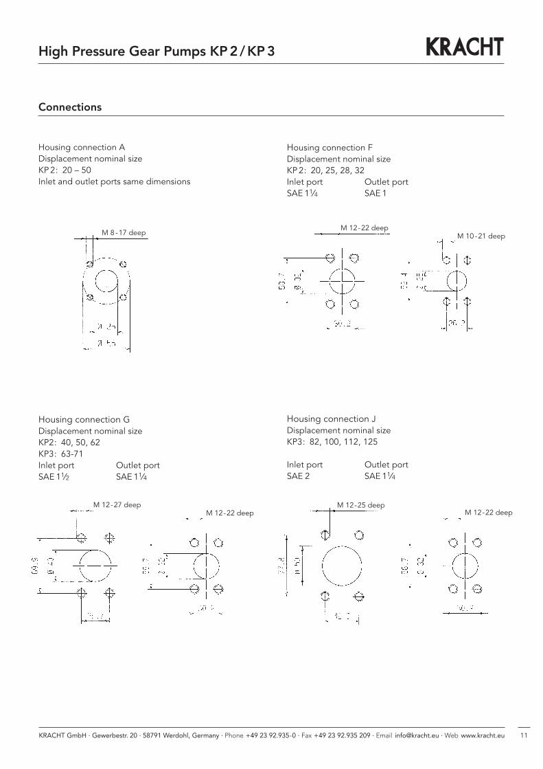
Connections
Housing connection ADisplacement nominal sizeKP2: 20 – 50Inlet and outlet ports same dimensions
Housing connection FDisplacement nominal sizeKP2: 20, 25, 28, 32Inlet port Outlet portSAE 11⁄4 SAE 1
Housing connection GDisplacement nominal sizeKP2: 40, 50, 62KP3: 63-71Inlet port Outlet portSAE 11⁄2 SAE 11⁄4
Housing connection JDisplacement nominal sizeKP3: 82, 100, 112, 125
Inlet port Outlet portSAE 2 SAE 11⁄4
High Pressure Gear Pumps KP2 /KP3
M 12-22 deepM 10 -21 deepM 8 -17 deep
M 12-22 deepM 12-25 deep
M 12-22 deepM 12-27 deep
12 KRACHT GmbH · Gewerbestr. 20 · 58791 Werdohl, Germany · Phone +49 23 92.935-0 · Fax +49 23 92.935 209 · Email [email protected] · Web www.kracht.eu
High Pressure Gear Pumps KP2 /KP3
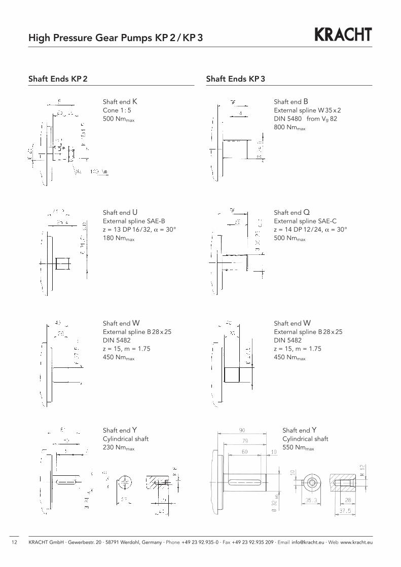
Shaft Ends KP2 Shaft Ends KP3
Shaft end KCone 1: 5500 Nmmax
Shaft end UExternal spline SAE-Bz = 13 DP 16/32, α = 30°180 Nmmax
Shaft end WExternal spline B28 x25DIN 5482z = 15, m = 1.75450 Nmmax
Shaft end YCylindrical shaft230 Nmmax
Shaft end BExternal spline W35x2DIN 5480 from Vg 82800 Nmmax
Shaft end QExternal spline SAE-Cz = 14 DP 12/24, α = 30°500 Nmmax
Shaft end WExternal spline B28 x25DIN 5482z = 15, m = 1.75450 Nmmax
Shaft end YCylindrical shaft550 Nmmax
132 KRACHT GmbH · Gewerbestr. 20 · 58791 Werdohl, Germany · Phone +49 23 92.935-0 · Fax +49 23 92.935 209 · Email [email protected] · Web www.kracht.eu
Beschreibung
Das Druckbegrenzungsventil SPV/SPVF ist ein direkt ge-steuertes Schieberventil für Einbau in Rohrleitungenund dient zur Absicherung von Niederdruck-Hydraulik-Kreisläufen. Der Leitungs-Anschluss kann mittels SAE-Flansch (3000 psi) oder Whitworth-Rohrgewinde (G)vorgenommen werden.
Hinweise- Bei stark lufthaltigen Medien sollte das Ventil vorzugsweise senkrecht, mit der Einstellschraube nach unten, montiert werden.
- Am Tankanschluss T des Ventils darf im durchströmten Zustand (Q > 0) kein Unterdruck entstehen, da an-sonsten keine Entlüftung des Ventils möglich ist und in Folge unerwünschte Schwingungen und Geräusche auftreten können. Sollte dies nicht vermeidbar sein, steht die Sonderlösung (S33) zur Verfügung.
Ventilaufbau
Der Ventilschieber 2 wird durch die Druckfeder 3gegen die Ringfläche a gedrückt und sperrt somit überden Durchmesser d den Druckanschluss P vom Tankanschluss T ab. Bei Erreichen des Öffnungsdrucks,eingestellt durch die Einstellschraube 4, gibt der Ventilschieber 2 den Flüssigkeitsstrom zum Tankanschluss frei. Der Federraum b wird durch die Bohrung c entlastet.Bei Inbetriebnahme des Ventils ist der Federraum b durchdie Entlüftungsschraube 5 (SW 4) zu entlüften.Die Ventile sind in verschiedenen Druckbereichen lieferbar, da jede Druckfeder infolge ihrer Charakteristiknur für einen begrenzten Einstellbereich geeignet ist.
Druckbegrenzungsventile SPV, SPVF direktgesteuert
Aufbau
1 Gehäuse2 Ventilschieber3 Druckfeder4 Einstellschraube5 Entlüftungsschraube6 Schutzkappe
T
Ø d
P
1
a
c
2
3
b
5
4
6
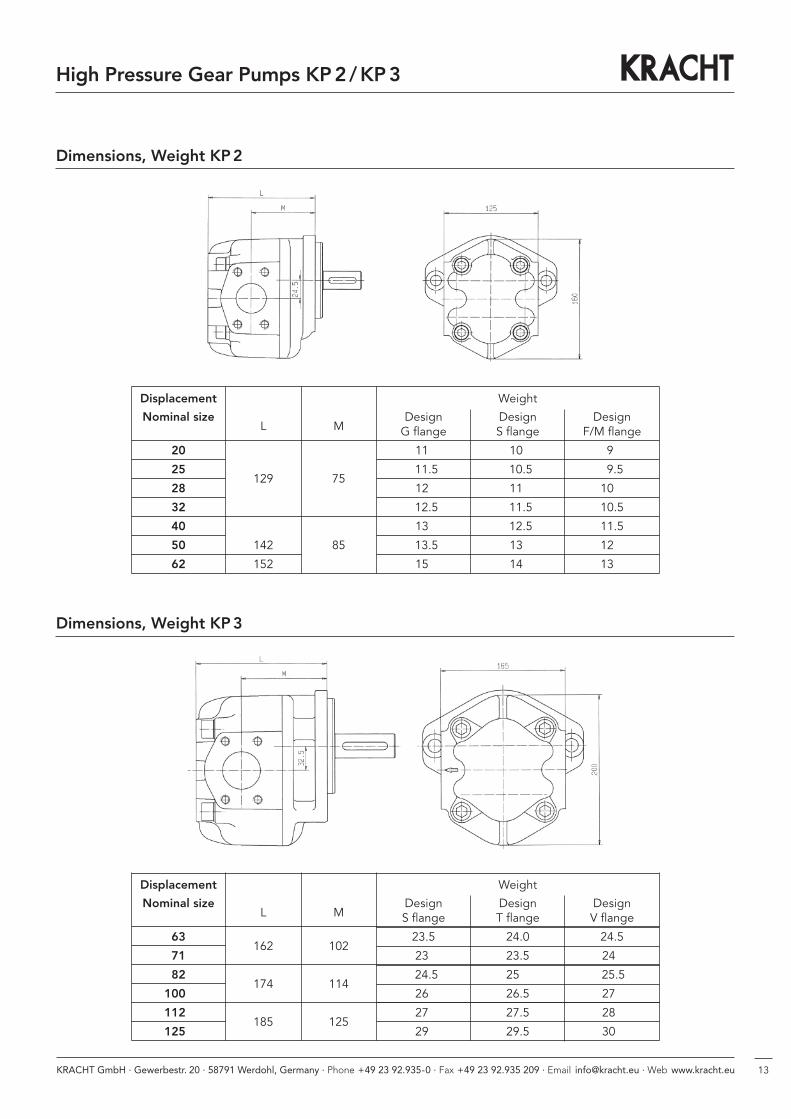
Dimensions, Weight KP2
Displacement Weight
Nominal size Design Design DesignL M G flange S flange F/M flange
20 11. 10. 9.0
25129 75
11.5 10.5 9.5
28 12. 11. 10.0
32 12.5 11.5 10.5
40 13. 12.5 11.5
50 142 85 13.5 13. 12.0
62 152 15. 14. 13.0
Dimensions, Weight KP3
Displacement Weight
Nominal size Design Design DesignL M S flange T flange V flange
63162 102
23.5 24.0 24.5
71 23. 23.5 24 .
82174 114
24.5. 25 . 25.5.
1000 26. 26.5. 27 .
1120185 125
27. 27.5 28 .
1250 29. 29.5. 30 .
High Pressure Gear Pumps KP2 /KP3
2 KRACHT GmbH · Gewerbestr. 20 · 58791 Werdohl, Germany · Phone +49 23 92.935-0 · Fax +49 23 92.935 209 · Email [email protected] · Web www.kracht.eu
Beschreibung
Das Druckbegrenzungsventil SPV/SPVF ist ein direkt ge-steuertes Schieberventil für Einbau in Rohrleitungenund dient zur Absicherung von Niederdruck-Hydraulik-Kreisläufen. Der Leitungs-Anschluss kann mittels SAE-Flansch (3000 psi) oder Whitworth-Rohrgewinde (G)vorgenommen werden.
Hinweise- Bei stark lufthaltigen Medien sollte das Ventil vorzugsweise senkrecht, mit der Einstellschraube nach unten, montiert werden.
- Am Tankanschluss T des Ventils darf im durchströmten Zustand (Q > 0) kein Unterdruck entstehen, da an-sonsten keine Entlüftung des Ventils möglich ist und in Folge unerwünschte Schwingungen und Geräusche auftreten können. Sollte dies nicht vermeidbar sein, steht die Sonderlösung (S33) zur Verfügung.
Ventilaufbau
Der Ventilschieber 2 wird durch die Druckfeder 3gegen die Ringfläche a gedrückt und sperrt somit überden Durchmesser d den Druckanschluss P vom Tankanschluss T ab. Bei Erreichen des Öffnungsdrucks,eingestellt durch die Einstellschraube 4, gibt der Ventilschieber 2 den Flüssigkeitsstrom zum Tankanschluss frei. Der Federraum b wird durch die Bohrung c entlastet.Bei Inbetriebnahme des Ventils ist der Federraum b durchdie Entlüftungsschraube 5 (SW 4) zu entlüften.Die Ventile sind in verschiedenen Druckbereichen lieferbar, da jede Druckfeder infolge ihrer Charakteristiknur für einen begrenzten Einstellbereich geeignet ist.
Druckbegrenzungsventile SPV, SPVF direktgesteuert
Aufbau
1 Gehäuse2 Ventilschieber3 Druckfeder4 Einstellschraube5 Entlüftungsschraube6 Schutzkappe
T
Ø d
P
1
a
c
2
3
b
5
4
6
14
High Pressure Gear Pumps KP2 /KP3
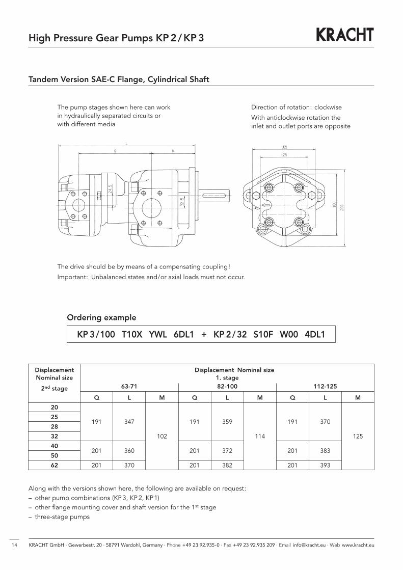
Tandem Version SAE-C Flange, Cylindrical Shaft
The pump stages shown here can workin hydraulically separated circuits orwith different media
The drive should be by means of a compensating coupling!
Important: Unbalanced states and/or axial loads must not occur.
Direction of rotation: clockwise
With anticlockwise rotation the inlet and outlet ports are opposite
Displacement Displacement Nominal sizeNominal size 1. stage
2nd stage 63-71 82-100 112-125
Q L M Q L M Q L M
20
25191 347 191 359 191 370
28
32 102 114 125
40201 360 201 372 201 383
50
62 201 370 201 382 201 393
Ordering example
KP 3/100 T10X YWL 6DL1 + KP 2/32 S10F W00 4DL1
Along with the versions shown here, the following are available on request:– other pump combinations (KP3, KP2, KP1)– other flange mounting cover and shaft version for the 1st stage– three-stage pumps
152 KRACHT GmbH · Gewerbestr. 20 · 58791 Werdohl, Germany · Phone +49 23 92.935-0 · Fax +49 23 92.935 209 · Email [email protected] · Web www.kracht.eu
Beschreibung
Das Druckbegrenzungsventil SPV/SPVF ist ein direkt ge-steuertes Schieberventil für Einbau in Rohrleitungenund dient zur Absicherung von Niederdruck-Hydraulik-Kreisläufen. Der Leitungs-Anschluss kann mittels SAE-Flansch (3000 psi) oder Whitworth-Rohrgewinde (G)vorgenommen werden.
Hinweise- Bei stark lufthaltigen Medien sollte das Ventil vorzugsweise senkrecht, mit der Einstellschraube nach unten, montiert werden.
- Am Tankanschluss T des Ventils darf im durchströmten Zustand (Q > 0) kein Unterdruck entstehen, da an-sonsten keine Entlüftung des Ventils möglich ist und in Folge unerwünschte Schwingungen und Geräusche auftreten können. Sollte dies nicht vermeidbar sein, steht die Sonderlösung (S33) zur Verfügung.
Ventilaufbau
Der Ventilschieber 2 wird durch die Druckfeder 3gegen die Ringfläche a gedrückt und sperrt somit überden Durchmesser d den Druckanschluss P vom Tankanschluss T ab. Bei Erreichen des Öffnungsdrucks,eingestellt durch die Einstellschraube 4, gibt der Ventilschieber 2 den Flüssigkeitsstrom zum Tankanschluss frei. Der Federraum b wird durch die Bohrung c entlastet.Bei Inbetriebnahme des Ventils ist der Federraum b durchdie Entlüftungsschraube 5 (SW 4) zu entlüften.Die Ventile sind in verschiedenen Druckbereichen lieferbar, da jede Druckfeder infolge ihrer Charakteristiknur für einen begrenzten Einstellbereich geeignet ist.
Druckbegrenzungsventile SPV, SPVF direktgesteuert
Aufbau
1 Gehäuse2 Ventilschieber3 Druckfeder4 Einstellschraube5 Entlüftungsschraube6 Schutzkappe
T
Ø d
P
1
a
c
2
3
b
5
4
6
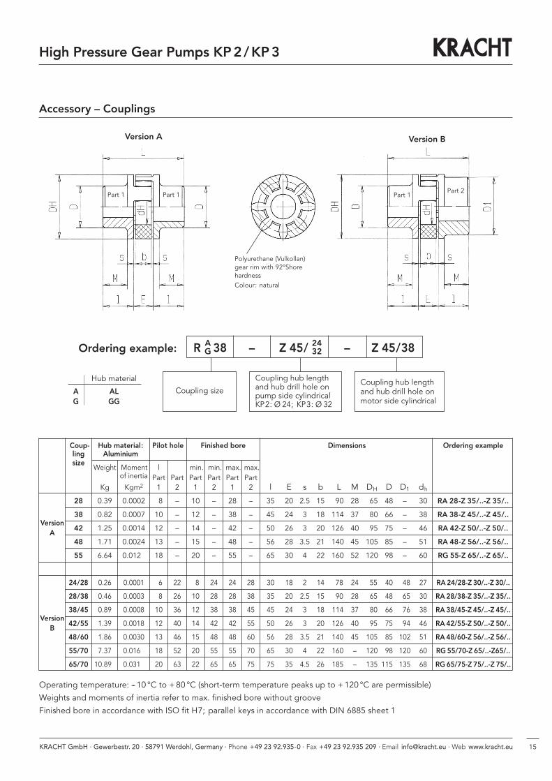
Accessory – Couplings
Coup- Hub material: Pilot hole Finished bore Dimensions Ordering exampleling Aluminiumsize
Weight Moment l min. min. max. max.of inertia Part Part Part Part Part Part
Kg Kgm2 1 2 1 2 1 2 l E s b L M DH D D1 dh28 0.39 0.0002 8 – 10 – 28 – 35 20 2.5 15 90 28 65 48 – 30 RA 28-Z 35/..-Z 35/..
Version38 0.82 0.0007 10 – 12 – 38 – 45 24 3 18 114 37 80 66 – 38 RA 38-Z 45/..-Z 45/..
A42 1.25 0.0014 12 – 14 – 42 – 50 26 3 20 126 40 95 75 – 46 RA 42-Z 50/..-Z 50/..
48 1.71 0.0024 13 – 15 – 48 – 56 28 3.5 21 140 45 105 85 – 51 RA 48-Z 56/..-Z 56/..
55 6.64 0.0120 18 – 20 – 55 – 65 30 4 22 160 52 120 98 – 60 RG 55-Z 65/..-Z 65/..
24/28 0.26 0.0001 6 22 8 24 24 28 30 18 2 14 78 24 55 40 48 27 RA24/28-Z 30/..-Z 30/..
28/38 0.46 0.0003 8 26 10 28 28 38 35 20 2.5 15 90 28 65 48 65 30 RA 28/38-Z 35/..-Z 35/..
Version38/45 0.89 0.0008 10 36 12 38 38 45 45 24 3 18 114 37 80 66 76 38 RA 38/45-Z 45/..-Z 45/..
B42/55 1.39 0.0018 12 40 14 42 42 55 50 26 3 20 126 40 95 75 94 46 RA 42/55-Z 50/..-Z 50/..
48/60 1.86 0.0030 13 46 15 48 48 60 56 28 3.5 21 140 45 105 85 102 51 RA 48/60-Z 56/..-Z 56/..
55/70 7.37 0.0160 18 52 20 55 55 70 65 30 4 22 160 – 120 98 120 60 RG 55/70-Z 65/..-Z65/..
65/70 10.890 0.0310 20 63 22 65 65 75 75 35 4.5 26 185 – 135 1150 135 68 RG 65/75-Z 75/..-Z 75/..
Operating temperature: -- 10 °C to +80 °C (short-term temperature peaks up to +120 °C are permissible)
Weights and moments of inertia refer to max. finished bore without groove
Finished bore in accordance with ISO fit H7; parallel keys in accordance with DIN 6885 sheet 1
Polyurethane (Vulkollan)gear rim with 92°ShorehardnessColour: natural
Version A Version B
Part 1 Part 1 Part 1Part 2
Coupling size
Coupling hub lengthand hub drill hole onpump side cylindricalKP2: Ø 24; KP3: Ø 32
Coupling hub length and hub drill hole onmotor side cylindrical
Ordering example:
Hub material
A ALG GG
High Pressure Gear Pumps KP2 /KP3
R 38 – Z 45/ – Z 45/38AG
2432
2 KRACHT GmbH · Gewerbestr. 20 · 58791 Werdohl, Germany · Phone +49 23 92.935-0 · Fax +49 23 92.935 209 · Email [email protected] · Web www.kracht.eu
Beschreibung
Das Druckbegrenzungsventil SPV/SPVF ist ein direkt ge-steuertes Schieberventil für Einbau in Rohrleitungenund dient zur Absicherung von Niederdruck-Hydraulik-Kreisläufen. Der Leitungs-Anschluss kann mittels SAE-Flansch (3000 psi) oder Whitworth-Rohrgewinde (G)vorgenommen werden.
Hinweise- Bei stark lufthaltigen Medien sollte das Ventil vorzugsweise senkrecht, mit der Einstellschraube nach unten, montiert werden.
- Am Tankanschluss T des Ventils darf im durchströmten Zustand (Q > 0) kein Unterdruck entstehen, da an-sonsten keine Entlüftung des Ventils möglich ist und in Folge unerwünschte Schwingungen und Geräusche auftreten können. Sollte dies nicht vermeidbar sein, steht die Sonderlösung (S33) zur Verfügung.
Ventilaufbau
Der Ventilschieber 2 wird durch die Druckfeder 3gegen die Ringfläche a gedrückt und sperrt somit überden Durchmesser d den Druckanschluss P vom Tankanschluss T ab. Bei Erreichen des Öffnungsdrucks,eingestellt durch die Einstellschraube 4, gibt der Ventilschieber 2 den Flüssigkeitsstrom zum Tankanschluss frei. Der Federraum b wird durch die Bohrung c entlastet.Bei Inbetriebnahme des Ventils ist der Federraum b durchdie Entlüftungsschraube 5 (SW 4) zu entlüften.Die Ventile sind in verschiedenen Druckbereichen lieferbar, da jede Druckfeder infolge ihrer Charakteristiknur für einen begrenzten Einstellbereich geeignet ist.
Druckbegrenzungsventile SPV, SPVF direktgesteuert
Aufbau
1 Gehäuse2 Ventilschieber3 Druckfeder4 Einstellschraube5 Entlüftungsschraube6 Schutzkappe
T
Ø d
P
1
a
c
2
3
b
5
4
6
16
High Pressure Gear Pumps KP2 /KP3
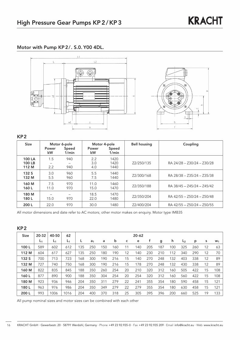
Motor with Pump KP2/. S.0. Y00 4DL.
Size Motor 6-pole Motor 4-pole Bell housing CouplingPower Speed Power SpeedkW 1/min kW 1/min
100 LA 1.5 940 2.2 1420100 LB – – 3.0 1420 Z2/250/135 RA 24/28 – Z30/24 – Z30/28112 M 2.2 940 4.0 1440
132 S 3.0 960 5.5 1440Z2/300/168 RA 28/38 – Z35/24 – Z35/38132 M 5.5 960 7.5 1440
160 M 7.5 970 11.0 1460Z2/350/188 RA 38/45 – Z45/24 – Z45/42160 L 11.0 970 15.0 1470
180 M – – 18.5 1470Z2/350/204 RA 42/55 – Z50/24 – Z50/48180 L 15.0 970 22.0 1480
200 L 22.0 970 30.0 1480 Z2/400/204 RA 42/55 – Z50/24 – Z50/55
All motor dimensions and date refer to AC motors; other motor makes on enquiry. Motor type IMB35
KP2
KP2Size 20-32 40-50 62 20-62
L1 L1 L1 L a1 a b c e f g h L2 p s w1
100 L 589 602 612 135 250 150 160 11 140 205 187 100 325 260 12 63
112 M 604 617 627 135 250 180 190 12 140 230 210 112 340 290 12 70
132 S 700 713 723 168 300 190 216 15 140 270 248 132 403 338 12 89
132 M 727 740 750 168 300 190 216 15 178 270 248 132 430 338 12 89
160 M 822 835 845 188 350 260 254 20 210 320 312 160 505 422 15 108
160 L 877 890 900 188 350 304 254 20 254 320 312 160 560 422 15 108
180 M 923 936 946 204 350 311 279 22 241 355 354 180 590 458 15 121
180 L 963 976 986 204 350 349 279 22 279 355 354 180 630 458 15 121
200 L 993 10060 10160 204 400 370 318 25 305 395 396 200 660 525 19 133
All pump nominal sizes and motor sizes can be combined with each other
172 KRACHT GmbH · Gewerbestr. 20 · 58791 Werdohl, Germany · Phone +49 23 92.935-0 · Fax +49 23 92.935 209 · Email [email protected] · Web www.kracht.eu
Beschreibung
Das Druckbegrenzungsventil SPV/SPVF ist ein direkt ge-steuertes Schieberventil für Einbau in Rohrleitungenund dient zur Absicherung von Niederdruck-Hydraulik-Kreisläufen. Der Leitungs-Anschluss kann mittels SAE-Flansch (3000 psi) oder Whitworth-Rohrgewinde (G)vorgenommen werden.
Hinweise- Bei stark lufthaltigen Medien sollte das Ventil vorzugsweise senkrecht, mit der Einstellschraube nach unten, montiert werden.
- Am Tankanschluss T des Ventils darf im durchströmten Zustand (Q > 0) kein Unterdruck entstehen, da an-sonsten keine Entlüftung des Ventils möglich ist und in Folge unerwünschte Schwingungen und Geräusche auftreten können. Sollte dies nicht vermeidbar sein, steht die Sonderlösung (S33) zur Verfügung.
Ventilaufbau
Der Ventilschieber 2 wird durch die Druckfeder 3gegen die Ringfläche a gedrückt und sperrt somit überden Durchmesser d den Druckanschluss P vom Tankanschluss T ab. Bei Erreichen des Öffnungsdrucks,eingestellt durch die Einstellschraube 4, gibt der Ventilschieber 2 den Flüssigkeitsstrom zum Tankanschluss frei. Der Federraum b wird durch die Bohrung c entlastet.Bei Inbetriebnahme des Ventils ist der Federraum b durchdie Entlüftungsschraube 5 (SW 4) zu entlüften.Die Ventile sind in verschiedenen Druckbereichen lieferbar, da jede Druckfeder infolge ihrer Charakteristiknur für einen begrenzten Einstellbereich geeignet ist.
Druckbegrenzungsventile SPV, SPVF direktgesteuert
Aufbau
1 Gehäuse2 Ventilschieber3 Druckfeder4 Einstellschraube5 Entlüftungsschraube6 Schutzkappe
T
Ø d
P
1
a
c
2
3
b
5
4
6
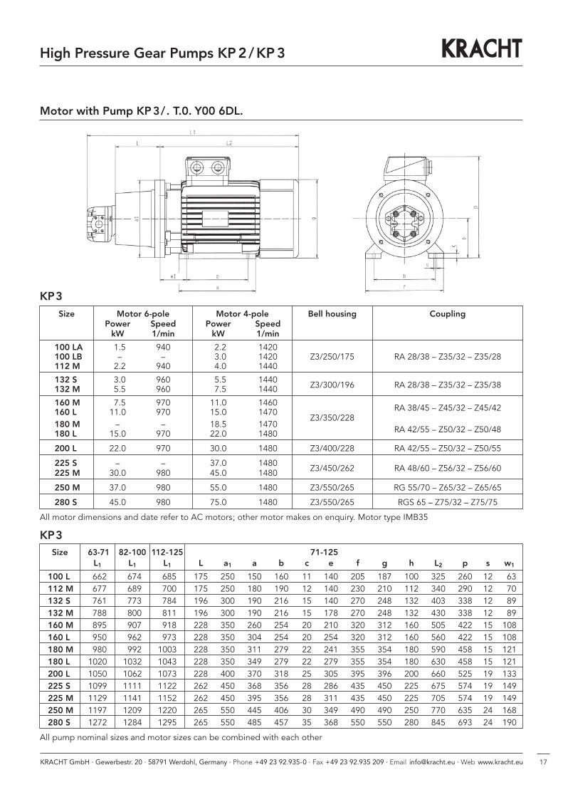
Motor with Pump KP3/. T.0. Y00 6DL.
KP3Size 63-71 82-100 112-125 71-125
L1 L1 L1 L a1 a b c e f g h L2 p s w1
100 L 662 674 685 175 250 150 160 11 140 205 187 100 325 260 12 63112 M 677 689 700 175 250 180 190 12 140 230 210 112 340 290 12 70132 S 761 773 784 196 300 190 216 15 140 270 248 132 403 338 12 89132 M 788 800 811 196 300 190 216 15 178 270 248 132 430 338 12 89160 M 895 907 918 228 350 260 254 20 210 320 312 160 505 422 15 108160 L 950 962 973 228 350 304 254 20 254 320 312 160 560 422 15 108180 M 980 992 1003 228 350 311 279 22 241 355 354 180 590 458 15 121180 L 1020 1032 1043 228 350 349 279 22 279 355 354 180 630 458 15 121200 L 1050 1062 1073 228 400 370 318 25 305 395 396 200 660 525 19 133225 S 1099 1111 1122 262 450 368 356 28 286 435 450 225 675 574 19 149225 M 1129 1141 1152 262 450 395 356 28 311 435 450 225 705 574 19 149250 M 1197 1209 1220 265 550 445 406 30 349 490 490 250 770 635 24 168280 S 1272 1284 1295 265 550 485 457 35 368 550 550 280 845 693 24 190
All pump nominal sizes and motor sizes can be combined with each other
Size Motor 6-pole Motor 4-pole Bell housing CouplingPower Speed Power SpeedkW 1/min kW 1/min
100 LA 1.5 940 2.2 1420100 LB – – 3.0 1420 Z3/250/175 RA 28/38 – Z35/32 – Z35/28112 M 2.2 940 4.0 1440
132 S 3.0 960 5.5 1440Z3/300/196 RA 28/38 – Z35/32 – Z35/38132 M 5.5 960 7.5 1440
160 M 7.5 970 11.0 1460RA 38/45 – Z45/32 – Z45/42160 L 11.0 970 15.0 1470
Z3/350/228180 M – – 18.5 1470
RA 42/55 – Z50/32 – Z50/48180 L 15.0 970 22.0 1480
200 L 22.0 970 30.0 1480 Z3/400/228 RA 42/55 – Z50/32 – Z50/55
225 S – – 37.0 1480Z3/450/262 RA 48/60 – Z56/32 – Z56/60225 M 30.0 980 45.0 1480
250 M 37.0 980 55.0 1480 Z3/550/265 RG 55/70 – Z65/32 – Z65/65
280 S 45.0 980 75.0 1480 Z3/550/265 RGS 65 – Z75/32 – Z75/75
All motor dimensions and date refer to AC motors; other motor makes on enquiry. Motor type IMB35
KP3
High Pressure Gear Pumps KP2 /KP3
2 KRACHT GmbH · Gewerbestr. 20 · 58791 Werdohl, Germany · Phone +49 23 92.935-0 · Fax +49 23 92.935 209 · Email [email protected] · Web www.kracht.eu
Beschreibung
Das Druckbegrenzungsventil SPV/SPVF ist ein direkt ge-steuertes Schieberventil für Einbau in Rohrleitungenund dient zur Absicherung von Niederdruck-Hydraulik-Kreisläufen. Der Leitungs-Anschluss kann mittels SAE-Flansch (3000 psi) oder Whitworth-Rohrgewinde (G)vorgenommen werden.
Hinweise- Bei stark lufthaltigen Medien sollte das Ventil vorzugsweise senkrecht, mit der Einstellschraube nach unten, montiert werden.
- Am Tankanschluss T des Ventils darf im durchströmten Zustand (Q > 0) kein Unterdruck entstehen, da an-sonsten keine Entlüftung des Ventils möglich ist und in Folge unerwünschte Schwingungen und Geräusche auftreten können. Sollte dies nicht vermeidbar sein, steht die Sonderlösung (S33) zur Verfügung.
Ventilaufbau
Der Ventilschieber 2 wird durch die Druckfeder 3gegen die Ringfläche a gedrückt und sperrt somit überden Durchmesser d den Druckanschluss P vom Tankanschluss T ab. Bei Erreichen des Öffnungsdrucks,eingestellt durch die Einstellschraube 4, gibt der Ventilschieber 2 den Flüssigkeitsstrom zum Tankanschluss frei. Der Federraum b wird durch die Bohrung c entlastet.Bei Inbetriebnahme des Ventils ist der Federraum b durchdie Entlüftungsschraube 5 (SW 4) zu entlüften.Die Ventile sind in verschiedenen Druckbereichen lieferbar, da jede Druckfeder infolge ihrer Charakteristiknur für einen begrenzten Einstellbereich geeignet ist.
Druckbegrenzungsventile SPV, SPVF direktgesteuert
Aufbau
1 Gehäuse2 Ventilschieber3 Druckfeder4 Einstellschraube5 Entlüftungsschraube6 Schutzkappe
T
Ø d
P
1
a
c
2
3
b
5
4
6
18
Note
High Pressure Gear Pumps KP2 /KP3

192 KRACHT GmbH · Gewerbestr. 20 · 58791 Werdohl, Germany · Phone +49 23 92.935-0 · Fax +49 23 92.935 209 · Email [email protected] · Web www.kracht.eu
Beschreibung
Das Druckbegrenzungsventil SPV/SPVF ist ein direkt ge-steuertes Schieberventil für Einbau in Rohrleitungenund dient zur Absicherung von Niederdruck-Hydraulik-Kreisläufen. Der Leitungs-Anschluss kann mittels SAE-Flansch (3000 psi) oder Whitworth-Rohrgewinde (G)vorgenommen werden.
Hinweise- Bei stark lufthaltigen Medien sollte das Ventil vorzugsweise senkrecht, mit der Einstellschraube nach unten, montiert werden.
- Am Tankanschluss T des Ventils darf im durchströmten Zustand (Q > 0) kein Unterdruck entstehen, da an-sonsten keine Entlüftung des Ventils möglich ist und in Folge unerwünschte Schwingungen und Geräusche auftreten können. Sollte dies nicht vermeidbar sein, steht die Sonderlösung (S33) zur Verfügung.
Ventilaufbau
Der Ventilschieber 2 wird durch die Druckfeder 3gegen die Ringfläche a gedrückt und sperrt somit überden Durchmesser d den Druckanschluss P vom Tankanschluss T ab. Bei Erreichen des Öffnungsdrucks,eingestellt durch die Einstellschraube 4, gibt der Ventilschieber 2 den Flüssigkeitsstrom zum Tankanschluss frei. Der Federraum b wird durch die Bohrung c entlastet.Bei Inbetriebnahme des Ventils ist der Federraum b durchdie Entlüftungsschraube 5 (SW 4) zu entlüften.Die Ventile sind in verschiedenen Druckbereichen lieferbar, da jede Druckfeder infolge ihrer Charakteristiknur für einen begrenzten Einstellbereich geeignet ist.
Druckbegrenzungsventile SPV, SPVF direktgesteuert
Aufbau
1 Gehäuse2 Ventilschieber3 Druckfeder4 Einstellschraube5 Entlüftungsschraube6 Schutzkappe
T
Ø d
P
1
a
c
2
3
b
5
4
6
Note
High Pressure Gear Pumps KP2 /KP3
KRACHT GmbH · Gewerbestraße 20 · 58791 Werdohl, Germany · fon +49 (0) 23 92 / 935-0 · fax +49 (0) 23 92 / 935 209
mail [email protected] · web www.kracht.eu
SVC / GB /11.14
Gear PumpsGear pumps for lubricating oilsupply equipment, low pressurefilling and feed systems, dosing andmixing systems.
Mobile HydraulicsSingle and multistage high pressuregear pumps, hydraulic motors andvalves for construction machinery,vehicle-mounted machines.
Flow MeasurementGear, turbine and screw type flow meters andelectronics for volume and flow metering technologyin hydraulics, processing and laquering technology.
Industrial Hydraulics /Test Bench ConstructionCetop directional control and proportionalvalves, hydraulic cylinders, pressure, quantityand stop valves for pipe and slab construction,hydraulic accessories for industrial hydraulics(mobile and stationary use).
Technology Test benches / Fluid Test benches.
Product Portfolio
KRACHT GmbH · Gewerbestraße 20 · 58791 Werdohl, Germany · Phone +49 23 92.935-0 · Fax +49 23 92.935 209
Email [email protected] · Web www.kracht.eu
Gear PumpsGear pumps for lubricating oil supply equipment, low pressure filling and feed systems, dosing and mixing systems.
HydraulicsSingle and multistage high pressure gear pumps and hydraulic motors for construction machinery, vehicle-mountedmachines.
Flow MeasurementGear, turbine and screw type flow meters and electronics for volume and flow metering techno logy in hydraulics, processing and laquering technology.
ValvesCetop directional control and proportionalvalves, pressure, quantity and stop valves forpipe and slab construction.
KP2-KP3/GB/05.18technical changes reserved