hidrostatiČni leŽaji hydrostatic bearings for … · hidrostatiČni leŽaji hydrostatic bearings...
TRANSCRIPT
358 Ventil 19 /2013/ 5
HIDROSTATIČNI LEŽAJI
Hydrostatic Bearings for Machine ToolsGeorg MÖRWALD, Jörg EDLER, Heinrich G. HOCHLEITNER
Abstract: Hydrostatic bearings have advantages due to their simple design, wear-free performance and good damping features. These properties make them applicable in machine tools. Hydrostatic bearings are built mostly with throttles, capillaries, separate pumps or progressive rate controllers. To meet the demand of high precision and accuracy, it is necessary to control the bearing gap. For the investigation of such a hydrostatic bearing, a test bed was built at the Institute of Production Engineering at the TU Graz.
This paper shows the construction of a test bed for simulating several operating conditions. The test bed includes six hydrostatic bearings of two kinds. For the measurement, three bearings have to be in operation. Forces up to 15 kN can be set as constant or predefined signals. The measured variables are the height, as well as the pressure of each hydrostatic bearing and the oil temperature. The test bed provides a basis for the development of controllers for hydrostatic bearings.
Key words: hydrostatic bearing, gap hight, pressure difference, measurement, controller
Dipl.-Ing. Georg Mörwald, Dipl.-Ing. Dr. techn. Jörg Edler, Prof. Dipl.-Ing. Dr. techn. Hei-nrich G. Hochleitner; all Institu-te of Production Engineering, TU Graz
■ 1 Introduction
The constant progress in industrial production technology always makes higher demands on precision and accuracy. In the field of machine tools, high precision and dynamics play a major role. Machine tool check rails can be designed in different ways. One of the solutions is a hydrostatic bearing. Good absorbability and fric-tionless movement are advantages over conventional bearings. To raise the accuracy of hydrostatic bearings, a control system is needed. This pa-per shows a test bed for the develo-ping and testing of such a controller.
■ 2 Hydrostatic bearing
The main item of this test bed is the hydrostatic bearing. The bed includes six bearings of two kinds. The bearings have square and ro-
und shapes and are positioned at an angle of 120°. Three bearings of the same kind are necessary for the operation. The three bearings de-fine a plane. The plane is designed in the form of the counterpiece su-pported by the bearing gap.
2.1 Design
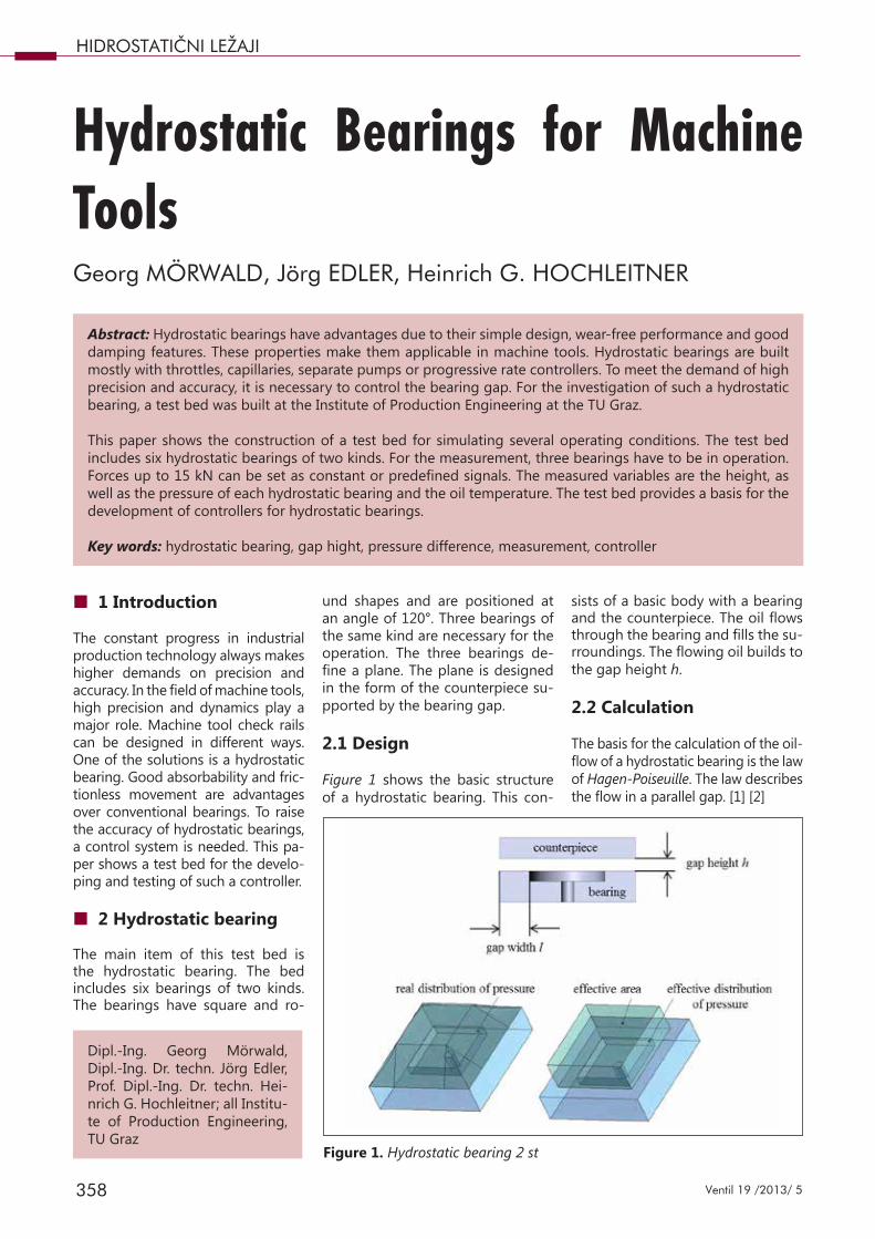
Figure 1 shows the basic structure of a hydrostatic bearing. This con-
sists of a basic body with a bearing and the counterpiece. The oil flows through the bearing and fills the su-rroundings. The flowing oil builds to the gap height h.
2.2 Calculation
The basis for the calculation of the oil-flow of a hydrostatic bearing is the law of Hagen-Poiseuille. The law describes the flow in a parallel gap. [1] [2]
Figure 1. Hydrostatic bearing 2 st
359Ventil 19 /2013/ 5
HIDROSTATIČNI LEŽAJI
lhbpQ⋅⋅⋅⋅∆
=η12
3
effT A
Fp =
(1)
The oilflow Q is calculated with the difference between the pressure inside and outside the bearing Δp. The equation is also influenced by the gap length b and the gap height h, as well as the dynamic viscosity of the oil η and the gap width l.
For the calculation of the bearing pressure, the real distribution of pressure is reduced to an effective distribution. The outcome of this is an effective area Aeff. The bearing pressure pT is solved by the force F divided by the effective area.
effT A
Fp =
(2)
■ 3 Test bed
3.1 Description
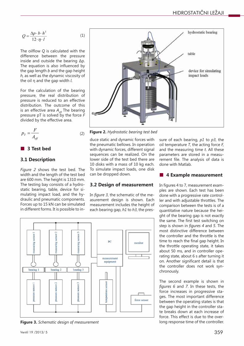
Figure 2 shows the test bed. The width and the length of the test bed are 600 mm. The height is 1310 mm. The testing bay consists of a hydro-static bearing, table, device for si-mulating impact load, and the hy-draulic and pneumatic components. Forces up to 15 kN can be simulated in different forms. It is possible to in-
duce static and dynamic forces with the pneumatic bellows. In operation with dynamic forces, different signal sequences can be realized. On the lower side of the test bed there are 10 disks with a mass of 10 kg each. To simulate impact loads, one disk can be dropped down.
3.2 Design of measurement
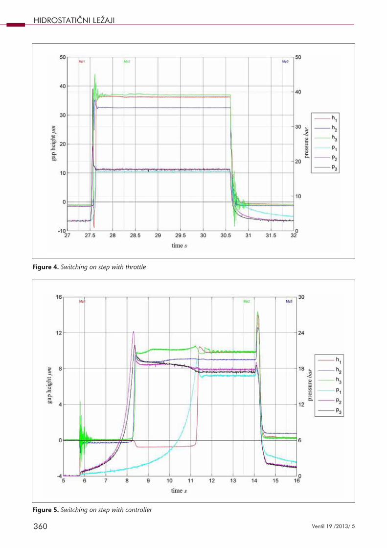
In figure 3, the schematic of the me-asurement design is shown. Each measurement includes the height of each bearing gap, h1 to h3, the pres-
sure of each bearing, p1 to p3, the oil temperature T, the acting force F, and the measuring time t. All these parameters are stored in a measu-rement file. The analysis of data is done with Matlab.
■ 4 Example measurement
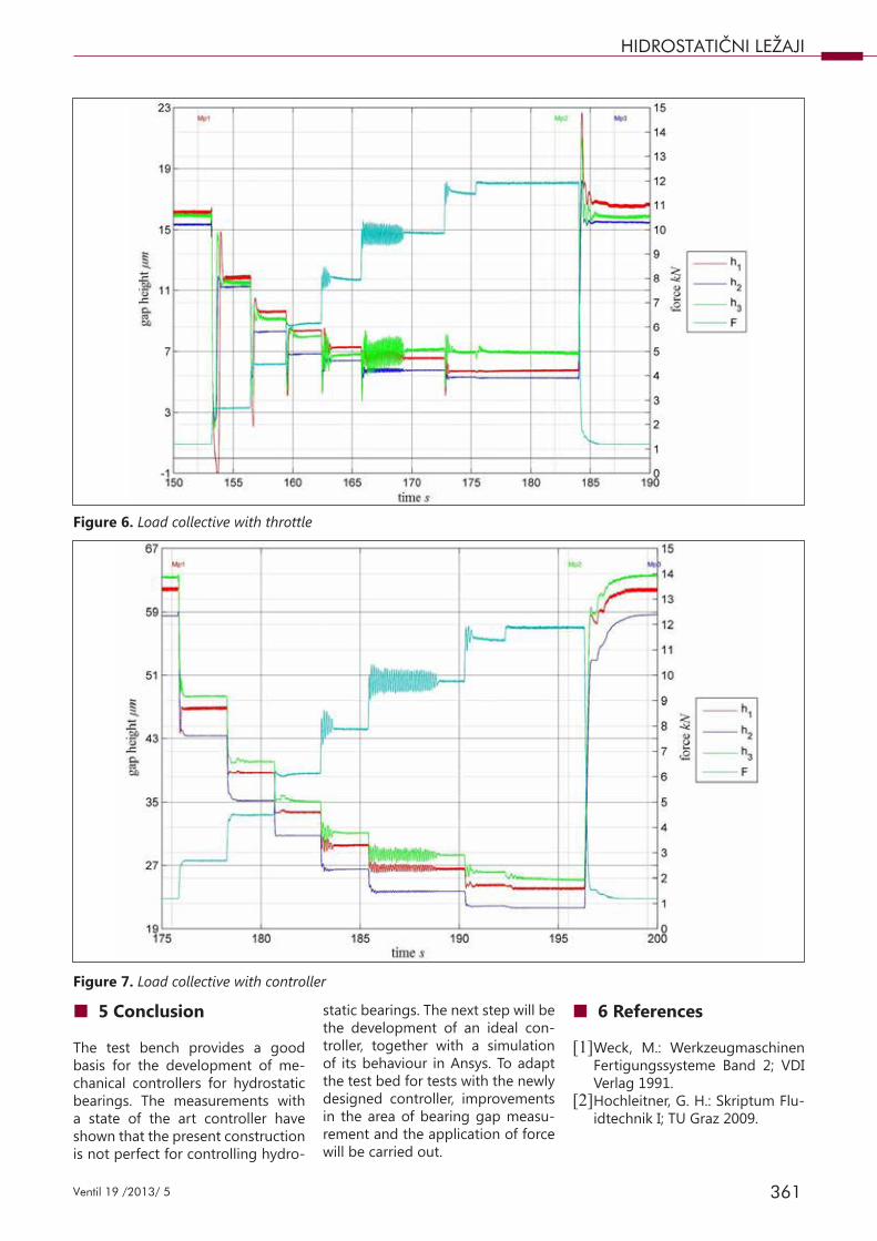
In figures 4 to 7, measurement exam-ples are shown. Each test has been done with a progressive rate control-ler and with adjustable throttles. The comparison between the tests is of a quantitative nature because the hei-ght of the bearing gap is not exactly the same. The first test switching on step is shown in figures 4 and 5. The most distinctive difference between the controller and the throttle is the time to reach the final gap height. In the throttle operating state, it takes about 50 ms, and in controller ope-rating state, about 6 s after turning it on. Another significant detail is that the controller does not work syn-chronously.
The second example is shown in figures 6 and 7. In these tests, the force increases in progressive sta-ges. The most important difference between the operating states is that the gap height in the controller sta-te breaks down at each increase of force. This effect is due to the over-long response time of the controller.
Figure 2. Hydrostatic bearing test bed
Figure 3. Schematic design of measurement
360 Ventil 19 /2013/ 5
HIDROSTATIČNI LEŽAJI
Figure 4. Switching on step with throttle
Figure 5. Switching on step with controller
361Ventil 19 /2013/ 5
HIDROSTATIČNI LEŽAJI
■ 5 Conclusion
The test bench provides a good basis for the development of me-chanical controllers for hydrostatic bearings. The measurements with a state of the art controller have shown that the present construction is not perfect for controlling hydro-
static bearings. The next step will be the development of an ideal con-troller, together with a simulation of its behaviour in Ansys. To adapt the test bed for tests with the newly designed controller, improvements in the area of bearing gap measu-rement and the application of force will be carried out.
■ 6 References
[1] Weck, M.: Werkzeugmaschinen Fertigungssysteme Band 2; VDI Verlag 1991.
[2] Hochleitner, G. H.: Skriptum Flu-idtechnik I; TU Graz 2009.
Figure 6. Load collective with throttle
Figure 7. Load collective with controller

362 Ventil 19 /2013/ 5
HIDROSTATIČNI LEŽAJI
Hidrostatični ležaji za obdelovalne stroje
Razširjeni povzetek
Prednost hidrostatičnih ležajev je v preprosti obliki, delujejo brez obrabe in se odlikujejo po dušenju vi-bracij. Omenjene lastnosti omogočajo hidrostatičnim ležajem uporabo tudi pri obdelovalnih strojih. Hidro-statični ležaji so večinoma vgrajeni z dušilkami, kapilarami, ločenimi črpalkami ali progresivnimi tokovnimi ventili. Zagotavljanje visoke natančnosti obdelovalnih strojev zahteva kontrolo višino ležajne reže. Na inšti-tutu za proizvodno inženirstvo v Gradcu je bilo razvito preizkuševališče za raziskave hidrostatičnih ležajev. Prispevek prikazuje zasnovo preizkuševališča za testiranje hidrostatičnih ležajev pri različnih pogojih. Preiz-kuševališče ima šest hidrostatičnih ležajev, od tega dve različni izvedbi. Pri meritvah morajo obratovati po trije hidrostatični ležaji hkrati. Obremenitev je lahko konstantna ali pa se spreminja po vnaprej definiranem signalu. Največja možna obremenitev je 15 kN. Statične in dinamične obremenitve testiranih hidrostatičnih ležajev se zagotovijo preko pnevmatičnih zračnih mehov, impulzne obremenitve pa preko trka uteži na spodnji strani ležaja.
Merjene vrednosti so višina reže, tlak in temperatura hidrostatičnega ležaja. Rezultati meritev podajajo višino reže v odvisnosti od obremenitve. Najvišja izmerjena višina reže je bila 48 μm, ko ni bilo bremena, najnižja pa 22 μm pri bremenu 12 kN. Na posameznem od treh hidrostatičnih ležajev je višina reže odsto-pala za največ 5 μm ne glede na višino obremenitve.
Predstavljeno preizkuševališče predstavlja osnovo za nadaljnji razvoj krmilnikov za krmiljenje in nadzor hidrostatičnih ležajev.
Ključne besede: hidrostatični ležaj, višina reže, tlačna razlika, meritev, krmilnikLPKH-oglas_A5_210x148mm_mar13_press.pdf 1 18.3.2013 9:33:46