hid description table to build hid descriptors hut1_12
TRANSCRIPT
HID Usage Tables 10/28/2004
Version 1.12
Please send comments via electronic mail to: [email protected]
Universal Serial Bus (USB)
©1996-2004 USB Implementers’ Forum—All rights reserved.
ii Universal Serial Bus HID Usage Tables
Version 1.12 October 28, 2004
Contributors Brian M. Bates – ELO Touchsystems
Robert Dezmelyk – LCS/Telegraphics
Robert Ingman – Microsoft Corporation
Rob Lieb – Symbol Technologies, Inc.
Steve McGowan – Intel (Editor)
Kenneth Ray – Microsoft Corporation
Steve Schumacher – LCS/Telegraphics
Nathan C. Sherman - Microsoft Corporation
Don Stern – TV Interactive
Mike Van Flandern – Microsoft Corporation
Remy Zimmerman – Logitech International
And many others.
Universal Serial Bus HID Usage Tables iii
Version 1.12 October 21, 2004
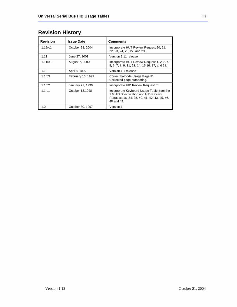
Revision History Revision Issue Date Comments 1.12rc1 October 28, 2004 Incorporate HUT Review Request 20, 21,
22, 23, 24, 25, 27, and 29.
1.11 June 27, 2001 Version 1.11 release
1.11rc1 August 7, 2000 Incorporate HUT Review Request 1, 2, 3, 4, 5, 6, 7, 8, 9, 11, 13, 14, 15,16, 17, and 18.
1.1 April 8, 1999 Version 1.1 release
1.1rc3 February 16, 1999 Correct barcode Usage Page ID. Corrected page numbering.
1.1rc2 January 21, 1999 Incorporate HID Review Request 51.
1.1rc1 October 13,1998 Incorporate Keyboard Usage Table from the 1.0 HID Specification and HID Review Requests 16, 34, 38, 40, 41, 42, 43, 45, 46, 48 and 49.
1.0 October 30, 1997 Version 1
iv Universal Serial Bus HID Usage Tables
Version 1.12 October 28, 2004
Copyright © 1996-2004, USB Implementers Forum All rights reserved.
INTELLECTUAL PROPERTY DISCLAIMER
THIS SPECIFICATION IS PROVIDED “AS IS” WITH NO WARRANTIES WHATSOEVER INCLUDING ANY WARRANTY OF MERCHANTABILITY, FITNESS FOR ANY PARTICULAR PURPOSE, OR ANY WARRANTY OTHERWISE ARISING OUT OF ANY PROPOSAL, SPECIFICATION, OR SAMPLE.
A LICENSE IS HEREBY GRANTED TO REPRODUCE AND DISTRIBUTE THIS SPECIFICATION FOR INTERNAL USE ONLY. NO OTHER LICENSE, EXPRESS OR IMPLIED, BY ESTOPPEL OR OTHERWISE, TO ANY OTHER INTELLECTUAL PROPERTY RIGHTS IS GRANTED OR INTENDED HEREBY.
AUTHORS OF THIS SPECIFICATION DISCLAIM ALL LIABILITY, INCLUDING LIABILITY FOR INFRINGEMENT OF PROPRIETARY RIGHTS, RELATING TO IMPLEMENTATION OF INFORMATION IN THIS SPECIFICATION. AUTHORS OF THIS SPECIFICATION ALSO DO NOT WARRANT OR REPRESENT THAT SUCH IMPLEMENTATION(S) WILL NOT INFRINGE SUCH RIGHTS.
All product names are trademarks, registered trademarks, or service marks of their respective owners.
Please send comments via electronic mail to hidcomments’at’usb.org, us the @ sign for ‘at’.
Universal Serial Bus HID Usage Tables v
Version 1.12 October 21, 2004
Table of Contents 1 INTRODUCTION.................................................................................................................................11
1.1 SCOPE ..............................................................................................................................................11 1.2 PURPOSE ..........................................................................................................................................11 1.3 RELATED DOCUMENTS ....................................................................................................................12 1.4 TERMS AND ABBREVIATIONS...........................................................................................................12
2 MANAGEMENT OVERVIEW...........................................................................................................13
3 USAGE PAGES.....................................................................................................................................14 3.1 HID USAGE TABLE CONVENTIONS ..................................................................................................15 3.2 HANDLING UNKNOWN USAGES .......................................................................................................15 3.3 USAGES AND UNITS .........................................................................................................................16 3.4 USAGE TYPES ..................................................................................................................................16
3.4.1 Usage Types (Controls)...........................................................................................................17 3.4.2 Usage Types (Data).................................................................................................................18 3.4.3 Usage Types (Collection) ........................................................................................................20 3.4.4 Alternate Types........................................................................................................................21
3.5 SYSTEM CONTROLS .........................................................................................................................22 3.5.1 Keyboard.................................................................................................................................22 3.5.2 Mice.........................................................................................................................................22 3.5.3 Joysticks ..................................................................................................................................22
3.6 HID LANGIDS................................................................................................................................22 3.6.1 Usage Data Descriptor (0x01) ................................................................................................24 3.6.2 Vendor Defined HID LANGID (0x3C - 0x3F) ........................................................................24
4 GENERIC DESKTOP PAGE (0X01) .................................................................................................26 4.1 APPLICATION USAGES .....................................................................................................................28 4.2 AXIS USAGES...................................................................................................................................29 4.3 MISCELLANEOUS CONTROLS ...........................................................................................................29
4.3.1 Resolution Multiplier...............................................................................................................30 4.4 VECTOR USAGES .............................................................................................................................31 4.5 SYSTEM CONTROLS .........................................................................................................................32
4.5.1 Power Controls .......................................................................................................................32 4.6 BUFFERED BYTES ............................................................................................................................33 4.7 DIRECTION PADS .............................................................................................................................33 4.8 FEATURE NOTIFICATIONS ................................................................................................................34 4.9 SOFTWARE FLOW CONTROLS...........................................................................................................34 4.10 SYSTEM DISPLAY CONTROLS...........................................................................................................35
5 SIMULATION CONTROLS PAGE (0X02).......................................................................................36 5.1 SPORTS SIMULATION DEVICE ..........................................................................................................37 5.2 FLIGHT SIMULATION DEVICES .........................................................................................................37 5.3 AUTOMOBILE SIMULATION DEVICES ...............................................................................................40 5.4 TANK SIMULATION DEVICES ...........................................................................................................41 5.5 MARITIME SIMULATION DEVICES ....................................................................................................41 5.6 TWO-WHEELED SIMULATION DEVICES ............................................................................................42 5.7 MISCELLANEOUS SIMULATION DEVICES..........................................................................................42
6 VR CONTROLS PAGE (0X03) ...........................................................................................................43
vi Universal Serial Bus HID Usage Tables
Version 1.12 October 28, 2004
7 SPORT CONTROLS PAGE (0X04)....................................................................................................45 7.1 STICK DEVICES ................................................................................................................................46 7.2 EXERCISE MACHINES .......................................................................................................................47
8 GAME CONTROLS PAGE (0X05).....................................................................................................48 8.1 3D GAME CONTROLLER...................................................................................................................49 8.2 PINBALL DEVICE..............................................................................................................................50 8.3 GUN DEVICE ....................................................................................................................................50 8.4 GAMEPADS.......................................................................................................................................51
8.4.1 Gamepad Button Collections...................................................................................................51 9 GENERIC DEVICE CONTROLS PAGE (0X06) ..............................................................................52
10 KEYBOARD/KEYPAD PAGE (0X07)............................................................................................53
11 LED PAGE (0X08) ............................................................................................................................61 11.1 KEYBOARD INDICATORS ..................................................................................................................63 11.2 TELEPHONY INDICATORS .................................................................................................................63 11.3 CONSUMER INDICATORS ..................................................................................................................64 11.4 MEDIA TRANSPORT INDICATORS......................................................................................................64 11.5 PRINTER INDICATORS.......................................................................................................................65 11.6 GENERAL DEVICE INDICATORS ........................................................................................................65
12 BUTTON PAGE (0X09)....................................................................................................................67
13 ORDINAL PAGE (0X0A).................................................................................................................68
14 TELEPHONY DEVICE PAGE (0X0B) ..........................................................................................69 14.1 TELEPHONY DEVICES.......................................................................................................................71 14.2 TELEPHONY KEY PAD USAGES ........................................................................................................71 14.3 CALL CONTROL................................................................................................................................72 14.4 SPEED DIAL CONTROLS....................................................................................................................73 14.5 VOICE MAIL CONTROLS...................................................................................................................73 14.6 LOCALLY GENERATED TONES..........................................................................................................73
15 CONSUMER PAGE (0X0C) ............................................................................................................75 15.1 GENERIC CONSUMER CONTROL DEVICE ..........................................................................................85 15.2 NUMERIC KEY PAD ..........................................................................................................................85 15.3 GENERAL CONTROLS .......................................................................................................................86 15.4 MENU CONTROLS.............................................................................................................................86 15.5 DISPLAY CONTROLS.........................................................................................................................86 15.6 SELECTION CONTROLS .....................................................................................................................87 15.7 TRANSPORT CONTROLS....................................................................................................................88 15.8 SEARCH CONTROLS..........................................................................................................................89 15.9 AUDIO CONTROLS............................................................................................................................89
15.9.1 Volume.....................................................................................................................................89 15.9.2 Balance....................................................................................................................................90 15.9.3 Bass .........................................................................................................................................90 15.9.4 Treble ......................................................................................................................................90 15.9.5 Other........................................................................................................................................91
15.10 SPEED CONTROLS.........................................................................................................................91 15.11 HOME AND SECURITY CONTROLS ................................................................................................91
Universal Serial Bus HID Usage Tables vii
Version 1.12 October 21, 2004
15.12 SPEAKER CHANNELS....................................................................................................................92 15.12.1 Audio Channels ...................................................................................................................92
15.13 PC THEATRE................................................................................................................................94 15.14 PROGRAMMABLE BUTTONS .........................................................................................................94 15.15 APPLICATION LAUNCH BUTTONS.................................................................................................94 15.16 GENERIC GUI APPLICATION CONTROLS ......................................................................................98
16 DIGITIZERS (0X0D)......................................................................................................................103 16.1 DIGITIZER DEVICES .......................................................................................................................104 16.2 DIGITIZER TRANSDUCER COLLECTION USAGES.............................................................................105 16.3 DIGITIZER REPORT FIELD USAGES.................................................................................................105
16.3.1 Digitizer-Specific Fields........................................................................................................105 16.3.2 Tilt Orientation......................................................................................................................106 16.3.3 Azimuth-Altitude Orientation ................................................................................................106
16.4 DIGITIZER SWITCH USAGES ...........................................................................................................107 17 UNICODE PAGE (0X10) ...............................................................................................................108
18 ALPHANUMERIC DISPLAY PAGE (0X14) ..............................................................................109 18.1 ALPHANUMERIC DISPLAY ..............................................................................................................111
18.1.1 Flags......................................................................................................................................111 18.1.2 Display Control.....................................................................................................................113 18.1.3 Scrolling ................................................................................................................................114 18.1.4 Character Transfers ..............................................................................................................114 18.1.5 Display Status........................................................................................................................115 18.1.6 Cursor Control ......................................................................................................................115 18.1.7 Font Loading.........................................................................................................................117 18.1.8 Character Formats................................................................................................................118
18.2 BITMAPPED DISPLAY .....................................................................................................................120 18.2.1 Display Attributes Report......................................................................................................121 18.2.2 Orientation ............................................................................................................................123 18.2.3 Palette Report........................................................................................................................124 18.2.4 Blit Report .............................................................................................................................125 18.2.5 Soft Button Report .................................................................................................................125
19 MEDICAL INSTRUMENT PAGE (0X40)...................................................................................126 19.1 ULTRASOUND DEVICES..................................................................................................................127 19.2 ACQUISITION CONTROLS ...............................................................................................................127 19.3 SIGNAL MODULATION ...................................................................................................................128 19.4 ACQUISITION AND DISPLAY MODE CONTROLS ..............................................................................128
APPENDIX A: USAGE EXAMPLES.......................................................................................................130 A.1 VOLUME CONTROL ........................................................................................................................130
A.1.1 Up/Down Buttons ..................................................................................................................130 A.1.2 Knob......................................................................................................................................130
A.2 TAPE JOG WHEEL ..........................................................................................................................130 A.3 RADIO BUTTONS ............................................................................................................................131
A.3.1 Mechanically Linked Radio Buttons......................................................................................131 A.3.2 Radio Buttons with No Mechanical Linkage .........................................................................131
A.4 NAMED ARRAY FIELD....................................................................................................................131 A.5 MULTIPLE INSTANCES OF A CONTROL ...........................................................................................132 A.6 MULTIPLE INSTANCES OF A MULTI-MODE LED ............................................................................132 A.7 DESKTOP TABLET EXAMPLE..........................................................................................................134
viii Universal Serial Bus HID Usage Tables
Version 1.12 October 28, 2004
A.8 A DEVICE WITH A DISPLAY ............................................................................................................137 A.9 REMOTE CONTROL.........................................................................................................................141 A.10 TELEPHONE ................................................................................................................................142
A.11.1 Multi-Line Snippet ..............................................................................................................145 A.12 JOYSTICK....................................................................................................................................145 A.13 GAME PAD .................................................................................................................................147 A.14 GRAPHIC EQUALIZER ........................................................................................................................148 19.5 SAMPLE BITMAPPED DISPLAY DEVICE...........................................................................................150
19.5.1 Example Bitmapped Display Report Descriptor ...................................................................151 APPENDIX B: DELIMITER EXAMPLE ................................................................................................154
APPENDIX C: PHYSICAL DESCRIPTOR EXAMPLE........................................................................156
USAGE INDEX ...........................................................................................................................................160
Universal Serial Bus HID Usage Tables ix
Version 1.12 October 21, 2004
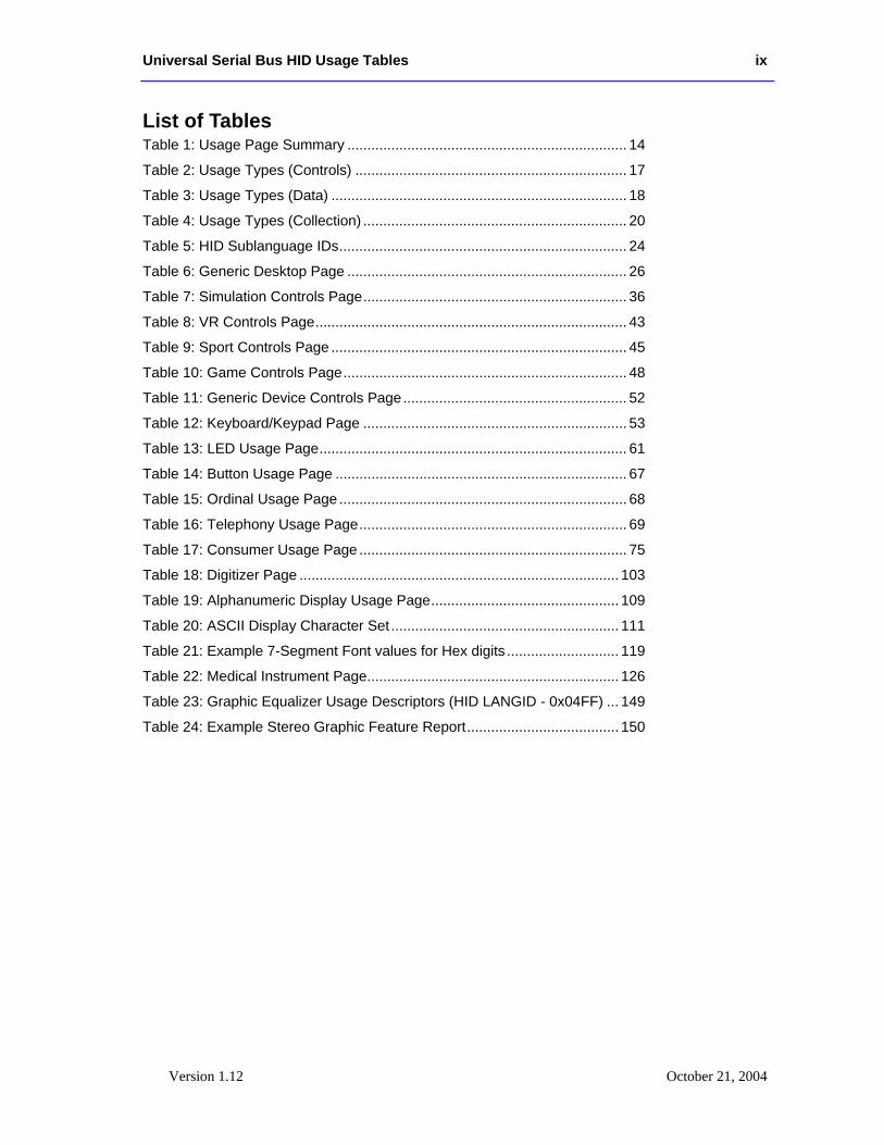
List of Tables Table 1: Usage Page Summary ...................................................................... 14 Table 2: Usage Types (Controls) .................................................................... 17 Table 3: Usage Types (Data) .......................................................................... 18 Table 4: Usage Types (Collection) .................................................................. 20 Table 5: HID Sublanguage IDs........................................................................ 24 Table 6: Generic Desktop Page ...................................................................... 26 Table 7: Simulation Controls Page.................................................................. 36 Table 8: VR Controls Page.............................................................................. 43 Table 9: Sport Controls Page .......................................................................... 45 Table 10: Game Controls Page....................................................................... 48 Table 11: Generic Device Controls Page........................................................ 52 Table 12: Keyboard/Keypad Page .................................................................. 53 Table 13: LED Usage Page............................................................................. 61 Table 14: Button Usage Page ......................................................................... 67 Table 15: Ordinal Usage Page ........................................................................ 68 Table 16: Telephony Usage Page................................................................... 69 Table 17: Consumer Usage Page ................................................................... 75 Table 18: Digitizer Page ................................................................................ 103 Table 19: Alphanumeric Display Usage Page............................................... 109 Table 20: ASCII Display Character Set ......................................................... 111 Table 21: Example 7-Segment Font values for Hex digits ............................ 119 Table 22: Medical Instrument Page............................................................... 126 Table 23: Graphic Equalizer Usage Descriptors (HID LANGID - 0x04FF) ... 149 Table 24: Example Stereo Graphic Feature Report...................................... 150
x Universal Serial Bus HID Usage Tables
Version 1.12 October 28, 2004
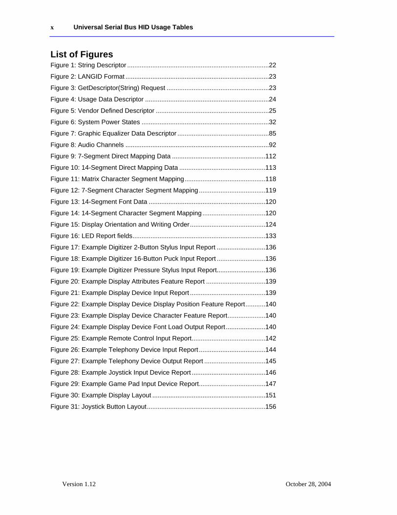
List of Figures Figure 1: String Descriptor ...............................................................................22 Figure 2: LANGID Format ................................................................................23 Figure 3: GetDescriptor(String) Request .........................................................23 Figure 4: Usage Data Descriptor .....................................................................24 Figure 5: Vendor Defined Descriptor ...............................................................25 Figure 6: System Power States .......................................................................32 Figure 7: Graphic Equalizer Data Descriptor ...................................................85 Figure 8: Audio Channels ................................................................................92 Figure 9: 7-Segment Direct Mapping Data ....................................................112 Figure 10: 14-Segment Direct Mapping Data ................................................113 Figure 11: Matrix Character Segment Mapping.............................................118 Figure 12: 7-Segment Character Segment Mapping .....................................119 Figure 13: 14-Segment Font Data .................................................................120 Figure 14: 14-Segment Character Segment Mapping ...................................120 Figure 15: Display Orientation and Writing Order..........................................124 Figure 16: LED Report fields..........................................................................133 Figure 17: Example Digitizer 2-Button Stylus Input Report ...........................136 Figure 18: Example Digitizer 16-Button Puck Input Report ...........................136 Figure 19: Example Digitizer Pressure Stylus Input Report...........................136 Figure 20: Example Display Attributes Feature Report .................................139 Figure 21: Example Display Device Input Report ..........................................139 Figure 22: Example Display Device Display Position Feature Report...........140 Figure 23: Example Display Device Character Feature Report.....................140 Figure 24: Example Display Device Font Load Output Report......................140 Figure 25: Example Remote Control Input Report.........................................142 Figure 26: Example Telephony Device Input Report .....................................144 Figure 27: Example Telephony Device Output Report ..................................145 Figure 28: Example Joystick Input Device Report .........................................146 Figure 29: Example Game Pad Input Device Report.....................................147 Figure 30: Example Display Layout ...............................................................151 Figure 31: Joystick Button Layout..................................................................156
Universal Serial Bus HID Usage Tables 11
Version 1.12 October 21, 2004
1 Introduction Usages are part of the HID Report descriptor and supply an application developer with information about what a control is actually measuring or reporting. In addition, a Usage tag can be used to indicate the vendor’s suggested use for a specific control or group of controls. While most of the items within a Report descriptor describe the format of the data—for example, three 8-bit fields—the Usage tags define what should be done with the data—for example, x, y, and z input. This feature allows a vendor to ensure that the user sees consistent function assignments to controls across applications. It is also the key feature within HID Report descriptors that allows system or application software to know the meaning of data items, or collections of data items, so the data items can be correctly interpreted or routed to the system or application software that consumes them.
1.1 Scope This document is the most current and complete list of currently defined usages. With the exception of the Keyboard/Keypad Page (0x07), this document is a superset of the usages defined in the USB Device Class Definition for Human Interface Devices (HID), also called the HID Specification. Keyboard/Keypad Page usages are listed in the HID Specification, and are not repeated in this document due to length. Usages for other pages listed in the HID Specification (Generic Desktop, LED, and Button pages) are repeated in this document with additional information. In case of a discrepancy, this document takes precedence over the HID Specification for those usages.
Usage definitions for Monitor, Power, Bar Code Scanner, and Point of Sale devices are in process as of this publication date and are not covered in this document. For details about those usages, see the device class specifications for those devices.
1.2 Purpose This document defines constants that can be interpreted by an application to identify the purpose and meaning of a data field in a HID report.
Usages are also used to define the meaning of groups of related data items. This is accomplished by the hierarchical assignment of usage information to collections. Usages identify the purpose of a collection and the items it contains. Each Input, Output, Feature, and/or Collection data item within a Collection item can be assigned a purpose with its own usage item. Usages assigned to a collection apply to the items within the collection.
In some cases a usage applied to a collection can redefine the meaning of the usages it contains. An example of this is the Usage Selected Indicator on the LED page.
Usages are also used to specify the meaning of each element within an Array data item.
12 Universal Serial Bus HID Usage Tables
Version 1.12 October 28, 2004
1.3 Related Documents Universal Serial Bus Specification, 1.0 Version (also referred to as the USB Specification)
USB PC Legacy Compatibility Specification
Universal Serial Bus Device Class Definition for Human Interface Devices (HID) (also referred to as the HID Specification)
USB Device Class Definition for Monitor Devices
USB Device Class Definition for Power Devices
USB Device Class Definition for Bar Code Scanners
USB Device Class Definition for Point of Sale Devices
USB Device Class Definition for Physical Interface Devices
Unicode Standard, version 1.1
International Character Encoding Standard, ISO/IEC10646-1 UCS-2
Open Arcade Architecture Device Data Format Specification
1.4 Terms and Abbreviations Application A software program that consumes the data generated by the HID device Input
reports, or that controls the HID device through Feature or Output reports. Applications can be games or other programs used by end users or system software components.
Array field The bit field created by an Input, Output, or Feature main item which is declared as an Array. An array field contains the index of a usage, not the usage value.
Control A control is used to operate or regulate a particular aspect of a device. In this document a control refers broadly to the physical entity on the device that the usage identifies.
Field The Input, Output, and Feature main items create a bit field in a report. The Report Size determines the field’s width and the associated usage determines the field’s purpose. The offset of a field in a report is determined by the fields that are declared before it.
Pad If a field is marked as a constant and there is no usage associated with it, the field will be treated as pad bits and ignored by host software.
Note: Fields created by Main items that do not have usages attached to them might not be accessible by applications. Whether such access is possible depends on the implementation of the HID device driver.
Usage Defines the purpose or meaning of an item.
Universal Serial Bus HID Usage Tables 13
Version 1.12 October 21, 2004
2 Management Overview This document provides lists of usages and their descriptions that significantly extend the list of usages provided in the HID Specification. A HID usage communicates the intended function or meaning of a particular control. Usages provide a description of the data items in a HID device’s Input, Output, and Feature reports. The existence of a defined usage does not guarantee that system or application software will recognize or utilize the data item. Although usages can be very powerful, there is a potential for misuse. The detail provided in this document will help minimize the misuse or misinterpretation of usages when they are applied by a device developer.
Usages have been organized into pages of related controls. Each usage has a usage ID, usage name and a detailed description. The usage names are mnemonics, not definitions. To avoid misleading interpretations based on the usage name, it is very important that a developer review a usage’s description in detail to ensure that it properly identifies the purpose of the control or device that the usage is attached to.
In theory, a usage can be attached to any type of HID control, variable, array, collection, and so forth. In reality, usages only make sense when they are attached to particular controls and used in certain ways. A relatively small set of usage types have been defined to help the application software developer better understand what to expect when a particular usage is found. Each usage has a usage type associated with it. The usage type identifies the item types, flag settings and bit fields organizations that are found with a particular usage.
Usages can also identify functional devices as a whole, thus providing an easy method for an application to identify devices that provide functions of interest. Such usages are found attached to application collections that are wrapped around all the items that describe a particular functional device, or a particular function in a complex device. Generally an application will query the HID driver for all application collection usages that it knows pertain to it. For example, a gaming device driver might look for Joystick and Game Pad usages, while a system mouse driver might look for Mouse, Digitizer Tablet and Touch Screen usages.
As a general rule, the usages selected by a device developer should be specific enough to dissuade inappropriate use by applications while remaining general enough to allow applications to take advantage of device features if they can. If uncertain, favor the more general usage to encourage broader application support for your device. An alternative is to use delimiters to define multiple usages associated with a single control or a device. For details, see Appendix B, “Delimiter Example.”
Some usage pages that are in the HID Specification are also found in this document. They are included here because either additional text has been provided to clarify how the usages are to be used , new usages have been added to the page, or both. No changes have been made to the usage values assigned in the HID Specification.
14 Universal Serial Bus HID Usage Tables
Version 1.12 October 28, 2004
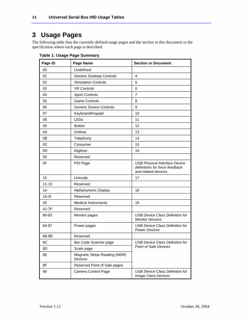
3 Usage Pages The following table lists the currently defined usage pages and the section in this document or the specification where each page is described.
Table 1: Usage Page Summary
Page ID Page Name Section or Document
00 Undefined
01 Generic Desktop Controls 4
02 Simulation Controls 5
03 VR Controls 0
04 Sport Controls 7
05 Game Controls 8
06 Generic Device Controls 9
07 Keyboard/Keypad 10
08 LEDs 11
09 Button 12
0A Ordinal 13
0B Telephony 14
0C Consumer 15
0D Digitizer 16
0E Reserved
0F PID Page USB Physical Interface Device definitions for force feedback and related devices.
10 Unicode 17
11-13 Reserved
14 Alphanumeric Display 18
15-3f Reserved
40 Medical Instruments 19
41-7F Reserved
80-83 Monitor pages USB Device Class Definition for Monitor Devices
84-87 Power pages USB Device Class Definition for Power Devices
88-8B Reserved
8C Bar Code Scanner page
8D Scale page
8E Magnetic Stripe Reading (MSR) Devices
8F Reserved Point of Sale pages
USB Device Class Definition for Point of Sale Devices
90 Camera Control Page USB Device Class Definition for Image Class Devices
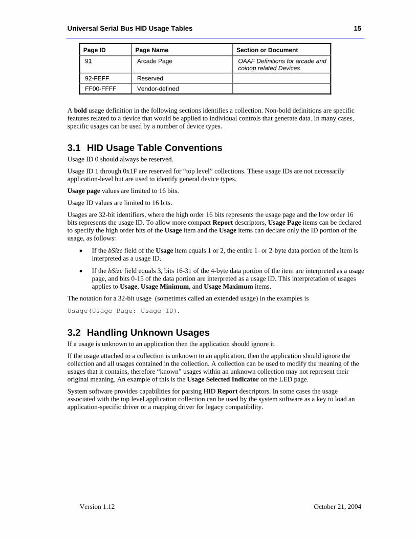
Universal Serial Bus HID Usage Tables 15
Version 1.12 October 21, 2004
Page ID Page Name Section or Document
91 Arcade Page OAAF Definitions for arcade and coinop related Devices
92-FEFF Reserved
FF00-FFFF Vendor-defined
A bold usage definition in the following sections identifies a collection. Non-bold definitions are specific features related to a device that would be applied to individual controls that generate data. In many cases, specific usages can be used by a number of device types.
3.1 HID Usage Table Conventions Usage ID 0 should always be reserved.
Usage ID 1 through 0x1F are reserved for “top level” collections. These usage IDs are not necessarily application-level but are used to identify general device types.
Usage page values are limited to 16 bits.
Usage ID values are limited to 16 bits.
Usages are 32-bit identifiers, where the high order 16 bits represents the usage page and the low order 16 bits represents the usage ID. To allow more compact Report descriptors, Usage Page items can be declared to specify the high order bits of the Usage item and the Usage items can declare only the ID portion of the usage, as follows:
• If the bSize field of the Usage item equals 1 or 2, the entire 1- or 2-byte data portion of the item is interpreted as a usage ID.
• If the bSize field equals 3, bits 16-31 of the 4-byte data portion of the item are interpreted as a usage page, and bits 0-15 of the data portion are interpreted as a usage ID. This interpretation of usages applies to Usage, Usage Minimum, and Usage Maximum items.
The notation for a 32-bit usage (sometimes called an extended usage) in the examples is
Usage(Usage Page: Usage ID).
3.2 Handling Unknown Usages If a usage is unknown to an application then the application should ignore it.
If the usage attached to a collection is unknown to an application, then the application should ignore the collection and all usages contained in the collection. A collection can be used to modify the meaning of the usages that it contains, therefore “known” usages within an unknown collection may not represent their original meaning. An example of this is the Usage Selected Indicator on the LED page.
System software provides capabilities for parsing HID Report descriptors. In some cases the usage associated with the top level application collection can be used by the system software as a key to load an application-specific driver or a mapping driver for legacy compatibility.
16 Universal Serial Bus HID Usage Tables
Version 1.12 October 28, 2004
3.3 Usages and Units For usages that declare data items as a measurement of time, distance, force, and so forth, an application must look at the units to properly interpret the value defined by a usage, unless:
1. The usage specifically declares Units as optional.
2. The usage description defines the units in which the value will be presented.
If Units are set to Optional or set to None (have not been declared) then an application can assume the usage represents a dimensionless value. Any application that ignores Units does so at its own risk.
A usage that declares itself to be a measurement of time would specify whether it was seconds or milliseconds by declaring Units and Unit Exponent prior to the respective Main item declaration. An example of this is the Flash On Time usage on the LED page, which is described as the duration that the indicator is illuminated in flash mode. The duration would be qualified by the values of Units and Unit Exponent.
When declaring Units for a main item, the Logical Minimum, Logical Maximum, Physical Minimum, Physical Maximum, and Unit Exponent items must also be declared.
In many cases the coordinate system assumes that the values can vary both positively and negatively from zero (0).
3.4 Usage Types Usages define a wide variety of device features. However, the way an application treats the data that they generate falls into a relatively small set of categories. This section provides descriptions of frequently used types of usages, primarily to save redundant text throughout this document. This list is not an exhaustive list of the possible usage types. Individual usage pages can declare their own usage types.
Each usage type describes how an application should treat the data generated by the Main item that the usage is attached to.
Usage type names are followed by an abbreviation that is used in the detailed usage description to identify the default type of a usage. In some cases usage types do not apply and the detailed description will identify how the usage is to be interpreted.
There are three basic types of information that are described by usages: controls, collections, and data. In this context, controls are identified with the state of a device (on/off, enable/disable, and so forth), collections group related controls and data together, and data comprises the remaining information that is passed between a device and the host.
Usage types are always considered to be the recommended method of handling a usage. Consult the usage’s definition to determine whether alternative usage types may apply.
Note
Note
Universal Serial Bus HID Usage Tables 17
Version 1.12 October 21, 2004
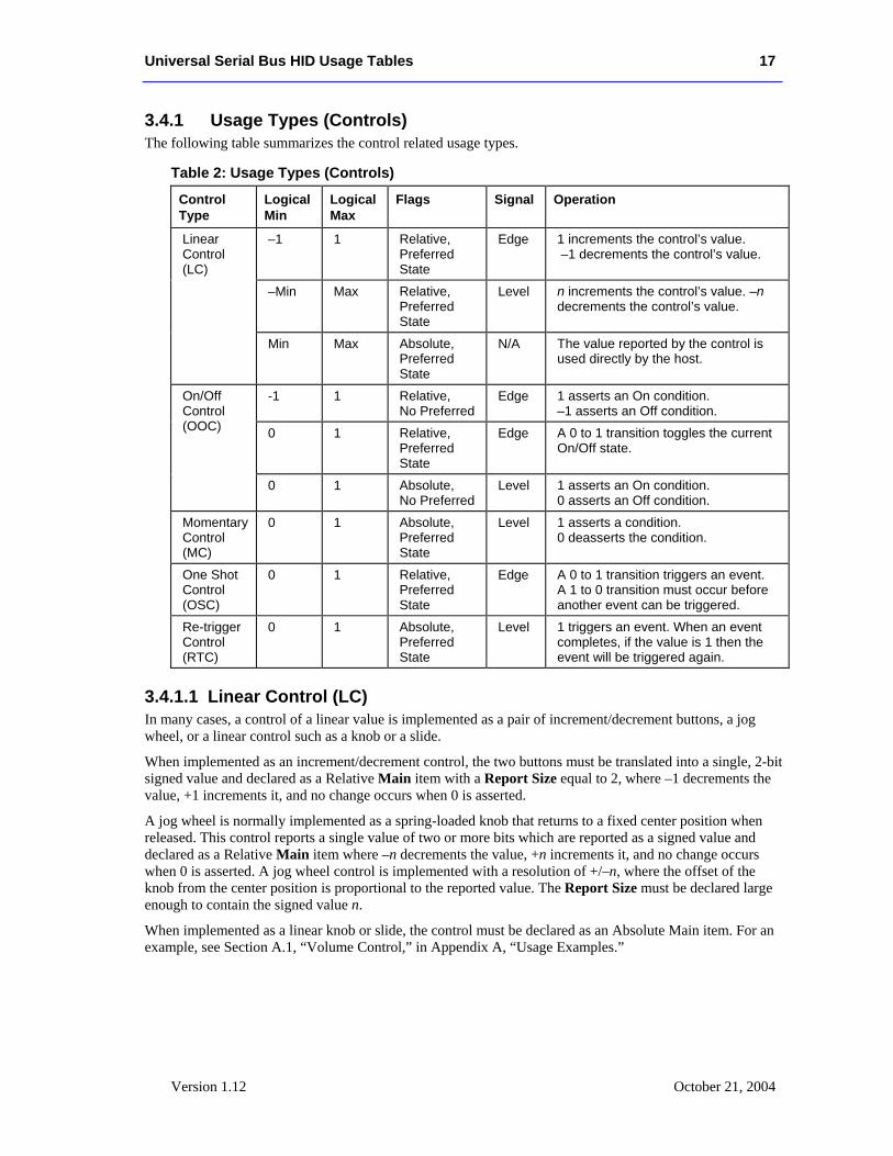
3.4.1 Usage Types (Controls) The following table summarizes the control related usage types.
Table 2: Usage Types (Controls)
Control Type
Logical Min
Logical Max
Flags Signal Operation
–1 1 Relative, Preferred State
Edge 1 increments the control’s value. –1 decrements the control’s value.
–Min Max Relative, Preferred State
Level n increments the control’s value. –n decrements the control’s value.
Linear Control (LC)
Min Max Absolute, Preferred State
N/A The value reported by the control is used directly by the host.
-1 1 Relative, No Preferred
Edge 1 asserts an On condition. –1 asserts an Off condition.
0 1 Relative, Preferred State
Edge A 0 to 1 transition toggles the current On/Off state.
On/Off Control (OOC)
0 1 Absolute, No Preferred
Level 1 asserts an On condition. 0 asserts an Off condition.
Momentary Control (MC)
0 1 Absolute, Preferred State
Level 1 asserts a condition. 0 deasserts the condition.
One Shot Control (OSC)
0 1 Relative, Preferred State
Edge A 0 to 1 transition triggers an event. A 1 to 0 transition must occur before another event can be triggered.
Re-trigger Control (RTC)
0 1 Absolute, Preferred State
Level 1 triggers an event. When an event completes, if the value is 1 then the event will be triggered again.
3.4.1.1 Linear Control (LC) In many cases, a control of a linear value is implemented as a pair of increment/decrement buttons, a jog wheel, or a linear control such as a knob or a slide.
When implemented as an increment/decrement control, the two buttons must be translated into a single, 2-bit signed value and declared as a Relative Main item with a Report Size equal to 2, where –1 decrements the value, +1 increments it, and no change occurs when 0 is asserted.
A jog wheel is normally implemented as a spring-loaded knob that returns to a fixed center position when released. This control reports a single value of two or more bits which are reported as a signed value and declared as a Relative Main item where –n decrements the value, +n increments it, and no change occurs when 0 is asserted. A jog wheel control is implemented with a resolution of +/–n, where the offset of the knob from the center position is proportional to the reported value. The Report Size must be declared large enough to contain the signed value n.
When implemented as a linear knob or slide, the control must be declared as an Absolute Main item. For an example, see Section A.1, “Volume Control,” in Appendix A, “Usage Examples.”
18 Universal Serial Bus HID Usage Tables
Version 1.12 October 28, 2004
3.4.1.2 On/Off Control (OOC) An On/Off Control can be implemented in any of the following ways:
• Two buttons, On and Off. The two buttons are encoded into a 2-bit signed value and declared as a Relative, No Preferred Main item with Logical Minimum and Logical Maximum of –1 and 1, respectively. The transition from 0 to –1 generates an Off condition and the transition from 0 to +1 generates an On condition. No change occurs when 0 is asserted.
• A single button that toggles the On/Off state each time it is pressed. (single throw momentary switch The single button is encoded into a 1-bit unsigned value and declared as an Relative, Preferred Main item with a Logical Minimum and Logical Maximum of 0 and 1, respectively. The transition from 0 to 1 toggles the current On/Off state. No change occurs on the 1 to 0 transition.
• A toggle switch that maintains the On/Off state mechanically. (toggle switch) This control is encoded into a 1-bit unsigned value and declared as an Absolute, No Preferred Main item with a Logical Minimum and Logical Maximum of 0 and 1, respectively. The assertion of 1 generates an On condition and the assertion of 0 generates an Off condition.
3.4.1.3 Momentary Control (MC) A Momentary Control is a basic push button. A Momentary Control is encoded into a 1-bit value and declared as an Absolute, Preferred Main item with a Logical Minimum and Logical Maximum of 0 and 1, respectively. A value of 1 generates an asserted condition and 0 generates a non-asserted condition. An example is a mouse button.
3.4.1.4 One Shot Control (OSC) A One Shot Control is a push button that triggers a single event or action. A One Shot Control is encoded into a 1-bit value and declared as a Relative, Preferred Main item with a Logical Minimum and Logical Maximum of 0 and 1, respectively. A 0 to 1 transition initiates an event. Nothing occurs on a 1 to 0 transition but it is required before another event can occur. An example is degauss.
3.4.1.5 Re-Trigger Control (RTC) A Re-Trigger Control is a push button that triggers a repeating event as long as it is asserted. A Re-Trigger Control is encoded into a 1-bit value and declared as an Absolute, Preferred Main item with a Logical Minimum and Logical Maximum of 0 and 1, respectively. A 0 to 1 transition initiates the first event. When each event terminates, if the control is still asserted (1) then another event will occur. An example is an auto-repeat fire button.
3.4.2 Usage Types (Data) The following table summarizes the data-related usage types.
Table 3: Usage Types (Data)
Type Flags Description
Selector (Sel) Array Contained in a Named Array (NAry).
Static Value (SV) Constant, Variable, Absolute A read-only multiple-bit value.
Static Flag (SF) Constant, Variable, Absolute A read-only single-bit value.
Dynamic Value (DV) Data, Variable, Absolute A read/write multiple-bit value.
Dynamic Flag (DF) Data, Variable, Absolute A read/write single-bit value.
Universal Serial Bus HID Usage Tables 19
Version 1.12 October 21, 2004
3.4.2.1 Selector (Sel) Selectors come in three forms:
• One selection of a set. Radio buttons are a mechanically linked set of buttons where one selection is always valid. This is a perfect example of the “one selection of a set” form. A radio button set is defined by a Main item with the Array flag set and the Report Count set to 1. The index returned in the array field corresponds to the pressed button (or selection). A usage must be declared for each selection. The array field never returns an index of NULL because one usage is always valid. An example is Stat Not Ready on the Alphanumeric Display page.
• N selections of a set. More than one selection (button) can be valid at a time. Multiple selections can be returned to the system at one time in a multi-byte array. The “n selections of a set” form is defined by a Main item with the Array flag set and the Report Count set to n, where n is the number of selections that can be reported in a single report. An example is a keyboard.
• Any selection of a set. The control is implemented as a set of bit fields in which each bit represents a single selection. This control is defined by a Main item with the Variable flag set and the Report Size equal to 1. The Report Count will be equal to the number of selections in the set.
Selectors therefore can be implemented in a number of ways: Array[1] (one selection of a set), Array[n] (n selections of a set), or bitmap (any selection of a set).
Optionally, the array field or set can be named by wrapping a set of Selectors in a logical collection with a usage attached to it. For details, see Section 3.4.3.1, “Named Array (NAry).”
3.4.2.2 Static Value (SV) Static values are used to declare a fixed features in a device. They are defined as Constant and treated as read-only information. Therefore, asserting this field in a Set_Report command has no defined effect.
3.4.2.3 Static Flag (SF) Static flags are used to declare the existence of a fixed feature in a device. If a Static Flag usage is found in a Report descriptor then the field must be read to determine whether the feature identified by the flag exists. A value of 1 indicates existence and a value of 0 indicates non-existence. The absence of a Static Flag usage implies that the flag is false or the feature defined by the flag is not supported by the device. A Static Flag must be declared as a Constant. To be accessible by applications, a Static Flag must have a usage assigned to it.
Static Flags are typically declared in a Feature report as a single-bit field where the value is always read as 1. Attempting to modify this field in a Set_Report command has no effect on a Static Flag.
3.4.2.4 Dynamic Flag (DF) Dynamic Flags are used to declare the existence of a host-controllable feature in a device. The absence of a Dynamic Flag usage implies that the flag is false or the feature defined by the flag is not supported by the device.
Dynamic Flags are typically declared in a report as a single-bit field, where a value of 1 returned by the device indicates that the feature is enabled. The assertion of 1 by the host will cause the feature to be evoked and the assertion of 0 indicates that the feature is to be disabled or ignored if the feature is a one-time event (such as Degauss or Clear Display). A Dynamic Flag Main item must be declared as Data.
20 Universal Serial Bus HID Usage Tables
Version 1.12 October 28, 2004
3.4.2.5 Dynamic Value (DV) A Dynamic Value is an n-bit field that contains a value associated with a control. The associated Main item will have the Data and Variable flags set. A Dynamic Value Main item must be declared as Data.
More advanced devices may allow a usage declared as a Static type to be Dynamic. Always check the Constant/Data flag in an Input, Output or Feature Main item.
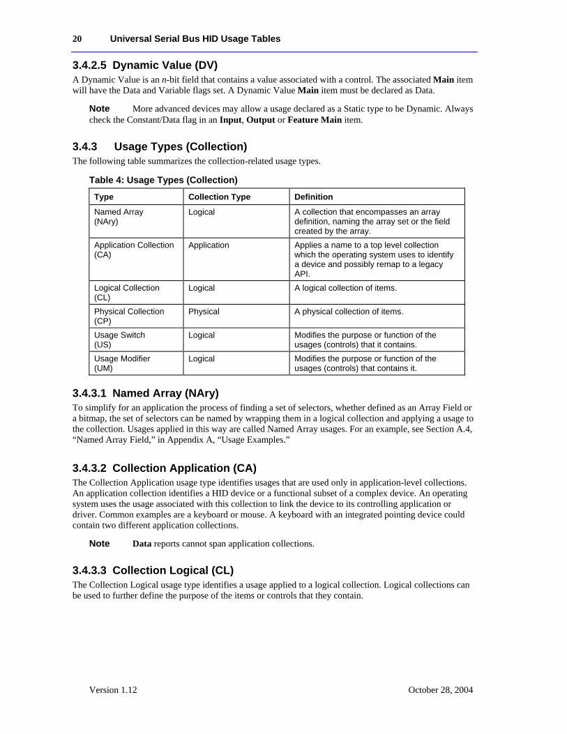
3.4.3 Usage Types (Collection) The following table summarizes the collection-related usage types.
Table 4: Usage Types (Collection)
Type Collection Type Definition
Named Array (NAry)
Logical A collection that encompasses an array definition, naming the array set or the field created by the array.
Application Collection (CA)
Application Applies a name to a top level collection which the operating system uses to identify a device and possibly remap to a legacy API.
Logical Collection (CL)
Logical A logical collection of items.
Physical Collection (CP)
Physical A physical collection of items.
Usage Switch (US)
Logical Modifies the purpose or function of the usages (controls) that it contains.
Usage Modifier (UM)
Logical Modifies the purpose or function of the usages (controls) that contains it.
3.4.3.1 Named Array (NAry) To simplify for an application the process of finding a set of selectors, whether defined as an Array Field or a bitmap, the set of selectors can be named by wrapping them in a logical collection and applying a usage to the collection. Usages applied in this way are called Named Array usages. For an example, see Section A.4, “Named Array Field,” in Appendix A, “Usage Examples.”
3.4.3.2 Collection Application (CA) The Collection Application usage type identifies usages that are used only in application-level collections. An application collection identifies a HID device or a functional subset of a complex device. An operating system uses the usage associated with this collection to link the device to its controlling application or driver. Common examples are a keyboard or mouse. A keyboard with an integrated pointing device could contain two different application collections.
Data reports cannot span application collections.
3.4.3.3 Collection Logical (CL) The Collection Logical usage type identifies a usage applied to a logical collection. Logical collections can be used to further define the purpose of the items or controls that they contain.
Note
Note
Universal Serial Bus HID Usage Tables 21
Version 1.12 October 21, 2004
3.4.3.4 Collection Physical (CP) The Collection Physical usage type identifies a usage applied to a physical collection, usually a collection of axes. A physical collection is used for a set of data items that represent data points collected at one geometric point. This is useful for sensing devices that may need to associate sets of measured or sensed data with a single point. It does not indicate that a set of data values comes from one device, such as a keyboard. In the case of a device that reports the position of multiple sensors, physical collections are used to show which data comes from which sensor.
3.4.3.5 Usage Switch (US) The Usage Switch usage type identifies a usage applied to a logical collection that modifies the purpose of the usages in that collection. An example is indicators. To avoid having to define a usage for every control that could possibly use an indicator (for example, Play/Play Indicator, etc.) a Usage Switch collection can be wrapped around a usage (Play) to create a indicator for the same function. Usage Switches often modify the type of the contained usage as well.
3.4.3.6 Usage Modifier (UM) The Usage Modifier usage type identifies a usage applied to a logical collection. This logical collection is always contained in another logical collection. The purpose and possibly the type of the usage attached to the encompassing collection is modified. For instance the usage attached to the encompassing collection may not normally be defined as a collection. For an example, see Section A.6, “Multiple Instances of a Multi-Mode LED,” in Appendix A, “Usage Examples.”
3.4.4 Alternate Types Usage types are a guide, not the rule. The flags, Logical Minimum and Logical Maximum values, and other Main item attributes must be evaluated by applications and system software to determine the true purpose, meaning, or interpretation of a control.
In many cases, a usage can take on the attributes of a usage type other than its default type. The alternate type can be declared by a collection in which the usage is found or implied by the way it is declared in a Report descriptor. For example, Usage In Use Indicator from the LED page is an example of an alternate usage type being applied to a usage. When a usage is wrapped in a Usage In Use Indicator collection, it becomes an On/Off Control (OOC).
In other cases, a usage can be declared as either a Static Value (SV) or a Dynamic Value (DV). For example, in a screen saver, the Screen Saver Delay might be fixed on one device and variable on another. The same thing can happen with usages declared as Static Flag (SF) or Dynamic Flag (DF).
Another example is a usage that is declared as either an On/Off Control (OOC) or a Selector (Sel). A device that can support a variety of operational modes will declare individual bits as On/Off Controls to identify which modes are enabled. However, when the device is running, only one mode will be in effect at a time. The device would then declare the same usage as a Selector and report this in a Named Array field to identify the mode associated with the current data. For example, a tape transport could have three states: Stopped, Paused, and Playing. This could be implemented as three individual bits where only one bit is true at a time, or as a 2-bit field in which 0 = Stopped, 1 = Paused, and 3 = Playing.
22 Universal Serial Bus HID Usage Tables
Version 1.12 October 28, 2004
3.5 System Controls Applications look at the usage applied to top-level application collections to identify devices. System software that supports keyboards, mice, and joysticks follow the same conventions. If a device vendor wants a device to be recognized by the system software as one of these devices, then the device must follow the conventions described in this section.
3.5.1 Keyboard Typical system software will search for application collections tagged with either a Keyboard or a Keypad usage. When found, the usages contained in these collections will be treated as standard system keyboard input. All devices that use these declarations will have their output routed to the same destination. That is, typing on any device will affect the active application.
3.5.2 Mice Typical system software will search for application collections tagged with either a Mouse or a Pointer usage. When found, the usages generated by these collections will be treated as standard system pointer input. All devices that use these declarations will have their output routed to the same destination. That is, moving any mouse will affect the system pointer.
3.5.3 Joysticks Typical system software will search for application collections tagged with either a Joystick or a Game Pad usage. When found, the usages generated by these collections will be treated as standard system joystick (gaming device) input. Devices that use these declarations will have their output routed to separate destinations, allowing multiple-player applications.
3.6 HID LANGIDs This section identifies a set of conventions that allow static data to be associated with individual controls. These conventions are an extension of the string descriptors that can currently be attached to controls.
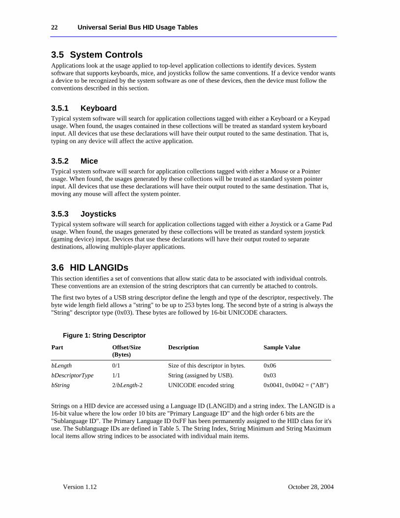
The first two bytes of a USB string descriptor define the length and type of the descriptor, respectively. The byte wide length field allows a "string" to be up to 253 bytes long. The second byte of a string is always the "String" descriptor type (0x03). These bytes are followed by 16-bit UNICODE characters.
Figure 1: String Descriptor
Part Offset/Size (Bytes)
Description Sample Value
bLength 0/1 Size of this descriptor in bytes. 0x06 bDescriptorType 1/1 String (assigned by USB). 0x03 bString 2/bLength-2 UNICODE encoded string 0x0041, 0x0042 = ("AB")
Strings on a HID device are accessed using a Language ID (LANGID) and a string index. The LANGID is a 16-bit value where the low order 10 bits are "Primary Language ID" and the high order 6 bits are the "Sublanguage ID". The Primary Language ID 0xFF has been permanently assigned to the HID class for it's use. The Sublanguage IDs are defined in Table 5. The String Index, String Minimum and String Maximum local items allow string indices to be associated with individual main items.
Universal Serial Bus HID Usage Tables 23
Version 1.12 October 21, 2004
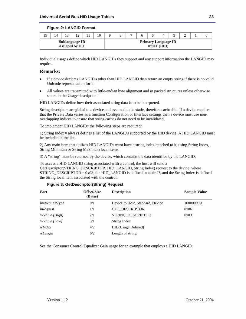
Figure 2: LANGID Format
15 14 13 12 11 10 9 8 7 6 5 4 3 2 1 0 Sublanguage ID Assigned by HID
Primary Language ID 0x0FF (HID)
Individual usages define which HID LANGIDs they support and any support information the LANGID may require.
Remarks: • If a device declares LANGID's other than HID LANGID then return an empty string if there is no valid
Unicode representation for it.
• All values are transmitted with little-endian byte alignment and in packed structures unless otherwise stated in the Usage description.
HID LANGIDs define how their associated string data is to be interpreted.
String descriptors are global to a device and assumed to be static, therefore cacheable. If a device requires that the Private Data varies as a function Configuration or Interface settings then a device must use non-overlapping indices to ensure that string caches do not need to be invalidated,
To implement HID LANGIDs the following steps are required:
1) String index 0 always defines a list of the LANGIDs supported by the HID device. A HID LANGID must be included in the list.
2) Any main item that utilizes HID LANGIDs must have a string index attached to it, using String Index, String Minimum or String Maximum local items.
3) A "string" must be returned by the device, which contains the data identified by the LANGID.
To access a HID LANGID string associated with a control, the host will send a GetDescriptor(STRING_DESCRIPTOR, HID_LANGID, String Index) request to the device, where STRING_DESCRIPTOR = 0x03, the HID_LANGID is defined in table ??, and the String Index is defined the String local item associated with the control.
Figure 3: GetDescriptor(String) Request
Part Offset/Size (Bytes)
Description Sample Value
bmRequestType 0/1 Device to Host, Standard, Device 10000000B bRequest 1/1 GET_DESCRIPTOR 0x06 WValue (High) 2/1 STRING_DESCRIPTOR 0x03 WValue (Low) 3/1 String Index wIndex 4/2 HID(Usage Defined) wLength 6/2 Length of string
See the Consumer Control:Equalizer Gain usage for an example that employs a HID LANGID.
24 Universal Serial Bus HID Usage Tables
Version 1.12 October 28, 2004
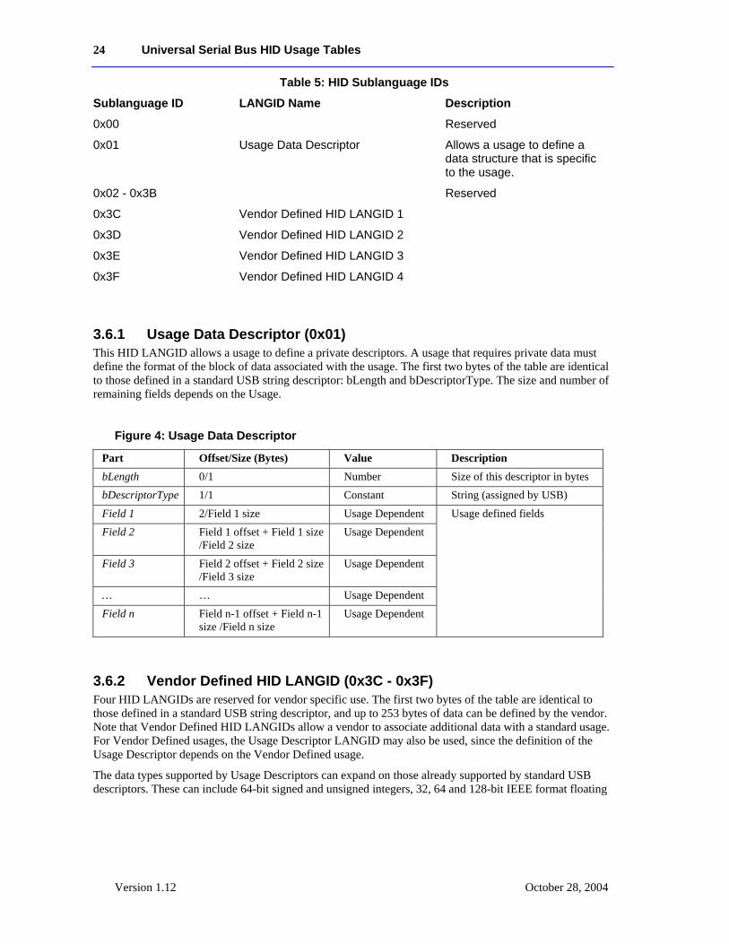
Table 5: HID Sublanguage IDs
Sublanguage ID LANGID Name Description
0x00 Reserved
0x01 Usage Data Descriptor Allows a usage to define a data structure that is specific to the usage.
0x02 - 0x3B Reserved
0x3C Vendor Defined HID LANGID 1
0x3D Vendor Defined HID LANGID 2
0x3E Vendor Defined HID LANGID 3
0x3F Vendor Defined HID LANGID 4
3.6.1 Usage Data Descriptor (0x01) This HID LANGID allows a usage to define a private descriptors. A usage that requires private data must define the format of the block of data associated with the usage. The first two bytes of the table are identical to those defined in a standard USB string descriptor: bLength and bDescriptorType. The size and number of remaining fields depends on the Usage.
Figure 4: Usage Data Descriptor
Part Offset/Size (Bytes) Value Description bLength 0/1 Number Size of this descriptor in bytes bDescriptorType 1/1 Constant String (assigned by USB) Field 1 2/Field 1 size Usage Dependent Field 2 Field 1 offset + Field 1 size
/Field 2 size Usage Dependent
Field 3 Field 2 offset + Field 2 size /Field 3 size
Usage Dependent
… … Usage Dependent Field n Field n-1 offset + Field n-1
size /Field n size Usage Dependent
Usage defined fields
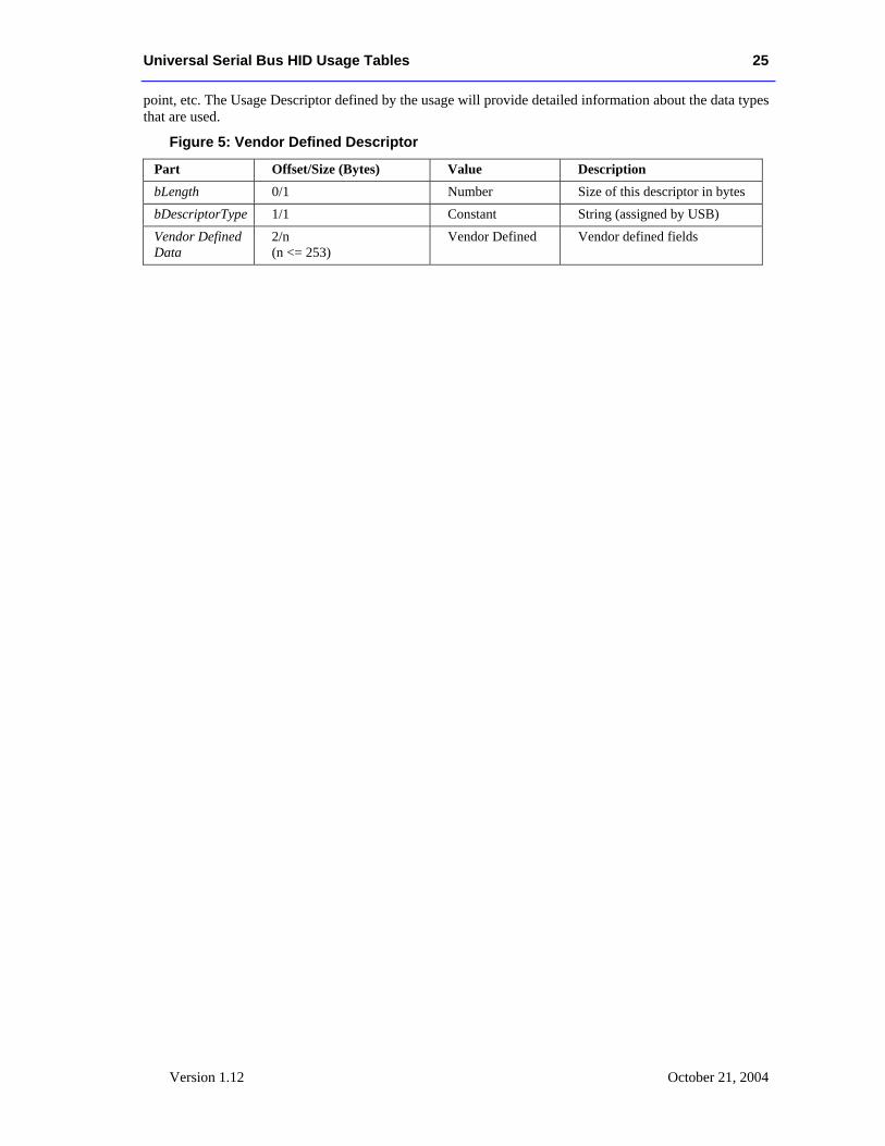
3.6.2 Vendor Defined HID LANGID (0x3C - 0x3F) Four HID LANGIDs are reserved for vendor specific use. The first two bytes of the table are identical to those defined in a standard USB string descriptor, and up to 253 bytes of data can be defined by the vendor. Note that Vendor Defined HID LANGIDs allow a vendor to associate additional data with a standard usage. For Vendor Defined usages, the Usage Descriptor LANGID may also be used, since the definition of the Usage Descriptor depends on the Vendor Defined usage.
The data types supported by Usage Descriptors can expand on those already supported by standard USB descriptors. These can include 64-bit signed and unsigned integers, 32, 64 and 128-bit IEEE format floating
Universal Serial Bus HID Usage Tables 25
Version 1.12 October 21, 2004
point, etc. The Usage Descriptor defined by the usage will provide detailed information about the data types that are used.
Figure 5: Vendor Defined Descriptor
Part Offset/Size (Bytes) Value Description bLength 0/1 Number Size of this descriptor in bytes bDescriptorType 1/1 Constant String (assigned by USB) Vendor Defined Data
2/n (n <= 253)
Vendor Defined Vendor defined fields
26 Universal Serial Bus HID Usage Tables
Version 1.12 October 28, 2004
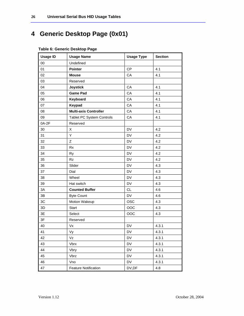
4 Generic Desktop Page (0x01)
Table 6: Generic Desktop Page
Usage ID Usage Name Usage Type Section
00 Undefined
01 Pointer CP 4.1
02 Mouse CA 4.1
03 Reserved
04 Joystick CA 4.1
05 Game Pad CA 4.1
06 Keyboard CA 4.1
07 Keypad CA 4.1
08 Multi-axis Controller CA 4.1
09 Tablet PC System Controls CA 4.1
0A-2F Reserved
30 X DV 4.2
31 Y DV 4.2
32 Z DV 4.2
33 Rx DV 4.2
34 Ry DV 4.2
35 Rz DV 4.2
36 Slider DV 4.3
37 Dial DV 4.3
38 Wheel DV 4.3
39 Hat switch DV 4.3
3A Counted Buffer CL 4.6
3B Byte Count DV 4.6
3C Motion Wakeup OSC 4.3
3D Start OOC 4.3
3E Select OOC 4.3
3F Reserved
40 Vx DV 4.3.1
41 Vy DV 4.3.1
42 Vz DV 4.3.1
43 Vbrx DV 4.3.1
44 Vbry DV 4.3.1
45 Vbrz DV 4.3.1
46 Vno DV 4.3.1
47 Feature Notification DV,DF 4.8
Universal Serial Bus HID Usage Tables 27
Version 1.12 October 21, 2004
Usage ID Usage Name Usage Type Section
48 Resolution Multiplier DV
49-7F Reserved
80 System Control CA 4.5
81 System Power Down OSC 4.5
82 System Sleep OSC 4.5.1
83 System Wake Up OSC 4.5.1
84 System Context Menu OSC 4.5
85 System Main Menu OSC 4.5
86 System App Menu OSC 4.5
87 System Menu Help OSC 4.5
88 System Menu Exit OSC 4.5
89 System Menu Select OSC 4.5
8A System Menu Right RTC 4.5
8B System Menu Left RTC 4.5
8C System Menu Up RTC 4.5
8D System Menu Down RTC 4.5
8E System Cold Restart OSC 4.5.1
8F System Warm Restart OSC 4.5.1
90 D-pad Up OOC 4.7
91 D-pad Down OOC 4.7
92 D-pad Right OOC 4.7
93 D-pad Left OOC 4.7
94-9F Reserved
A0 System Dock OSC 4.5.1
A1 System Undock OSC 4.5.1
A2 System Setup OSC 4.5.1
A3 System Break OSC 4.9
A4 System Debugger Break OSC 4.9
A5 Application Break OSC 4.9
A6 Application Debugger Break OSC 4.9
A7 System Speaker Mute OSC 4.5.1
A8 System Hibernate OSC 4.5.1
A9-AF Reserved
B0 System Display Invert OSC 4.10
B1 System Display Internal OSC 4.10
B2 System Display External OSC 4.10
B3 System Display Both OSC 4.10
B4 System Display Dual OSC 4.10
B5 System Display Toggle Int/Ext OSC 4.10
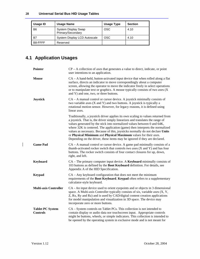
28 Universal Serial Bus HID Usage Tables
Version 1.12 October 28, 2004
Usage ID Usage Name Usage Type Section
B6 System Display Swap Primary/Secondary
OSC 4.10
B7 System Display LCD Autoscale OSC 4.10
B8-FFFF Reserved
4.1 Application Usages
Pointer CP – A collection of axes that generates a value to direct, indicate, or point user intentions to an application.
Mouse CA – A hand-held, button-activated input device that when rolled along a flat surface, directs an indicator to move correspondingly about a computer screen, allowing the operator to move the indicator freely in select operations or to manipulate text or graphics. A mouse typically consists of two axes (X and Y) and one, two, or three buttons.
Joystick CA – A manual control or cursor device. A joystick minimally consists of two variable axes (X and Y) and two buttons. A joystick is typically a rotational motion sensor. However, for legacy reasons, it is defined using linear axes.
Traditionally, a joystick driver applies its own scaling to values returned from a joystick. That is, the driver simply linearizes and translates the range of values generated by the stick into normalized values between 0 and 64K, where 32K is centered. The application (game) then interprets the normalized values as necessary. Because of this, joysticks normally do not declare Units or Physical Minimum and Physical Maximum values for their axes. Depending on the driver, these items may be ignored if they are declared.
Game Pad CA – A manual control or cursor device. A game pad minimally consists of a thumb-activated rocker switch that controls two axes (X and Y) and has four buttons. The rocker switch consists of four contact closures for up, down, right, and left.
Keyboard CA – The primary computer input device. A Keyboard minimally consists of 103 buttons as defined by the Boot Keyboard definition. For details, see Appendix A of the HID Specification.
Keypad CA – Any keyboard configuration that does not meet the minimum requirements of the Boot Keyboard. Keypad often refers to a supplementary calculator-style keyboard.
Multi-axis Controller CA - An input device used to orient eyepoints and or objects in 3 dimensional space. A Multi-axis Controller typically consists of six, variable axes (X, Y, Z, Rx, Ry and Rz) and is used by CAD/digital content creation applications for model manipulation and visualization in 3D space. The device may incorporate zero or more buttons.
Tablet PC System Controls
CA – System controls on Tablet PCs. This collection is not intended to contain display or audio data nor touchscreen input. Appropriate controls might be buttons, wheels, or simple indicators. This collection is intended to be opened by the operating system in exclusive mode and is not meant for
Universal Serial Bus HID Usage Tables 29
Version 1.12 October 21, 2004
application developers to open directly.
4.2 Axis Usages For X, Y, Z, Rx, Ry, and Rz, the declaration of Units is optional. If Units is None or not declared, these values should be considered as dimensionless.
X DV – A linear translation in the X direction. Report values should increase as the control’s position is moved from left to right.
Y DV – A linear translation in the Y direction. Report values should increase as the control’s position is moved from far to near.
Z DV – A linear translation in the Z direction. Report values should increase as the control’s position is moved from high to low (Z).
Rx DV – A rotation about the X axis. Angular position report values follow the righthand rule.
Ry DV – A rotation about the Y axis. Angular position report values follow the righthand rule.
Rz DV – A rotation about the Z axis. Angular position report values follow the righthand rule.
4.3 Miscellaneous Controls
Slider DV – A linear control for generating a variable value, normally in the form of a thumb slide in a slot. Report values should increase as controls are moved from near to far.
Dial DV – A rotary control for generating a variable value, normally in the form of a knob spun by the index finger and thumb. Report values should increase as controls are spun clockwise. This usage does not follow the HID orientation conventions.
Wheel DV – A rotary control for generating a variable value, normally rolled, unlike a dial. Report values should increase as controls are rolled forward, away from the user. This usage does not follow the HID orientation conventions.
Hat Switch DV – A specialized mechanical configuration of switches generating a variable value with a null state. The switches are arranged around a springloaded knob. When the knob is tilted in the direction of a switch, its contacts are closed. A typical example is four switches that are capable of generating information about four possible directions in which the knob can be tilted. Intermediate positions can also be decoded if the hardware allows two switches to be reported simultaneously.
Motion Wakeup DF – Enables the generation of a USB remote wakeup when the device detects motion. Motion Wakeup is always enabled after a USB Reset event is detected by the device. Then host can also assume that the state of the Motion Wakeup flag is maintained while the device is suspended.
30 Universal Serial Bus HID Usage Tables
Version 1.12 October 28, 2004
For example, a mouse may generate a remote wakeup when a button is pressed or when it is moved. For some implementations, a laptop user may want to disable the wakeup on motion because it draws more power.
Start OOC - Session start button. Initiates a session within an application .
Select OOC - Application option select button. Selects application configuration options.
Resolution Multiplier DV - DV Defines a Resolution Multiplier for a Control
4.3.1 Resolution Multiplier A HID device describes the resolution of a control by using the methods described in the HID Specification, v1.11, section 6.2.2.7 “Global Items – Remarks”. However, the resolution of a control in this model is static. If a device has the capability to vary the resolution of one or more of its controls, the resolution of those controls can be set by defining an associated Resolution Multiplier control.
The Resolution Multiplier control must be contained in the same Logical Collection as the control(s) to which it is to be applied. If no Resolution Multiplier is defined, then the Resolution Multiplier defaults to 1. If more than one control exists in a Logical Collection, the Resolution Multiplier is associated with all controls in the collection. If no Logical Collection is defined, the Resolution Multiplier is associated with all controls in the report.
The Resolution Multiplier is applied after all the normal resolution calculations have been performed for an affected control. The Resolution Multiplier is calculated as below:
( ) ntUnitExponePMinPMinPMaxLMinLMaxLMinRMVMultiplieresolutiuonEffectiveR 10** ⎟⎟
⎠
⎞⎜⎜⎝
⎛+⎟
⎠⎞
⎜⎝⎛ −
−−
=
where RMV = Resolution Multiplier Value, LMin = Logical Minimum, LMax = Logical Maximum, PMin = Physical Minimum, and PMax = Physical Maximum
For example, if a Wheel Control is defined as below: Usage Page Generic Desktop (0x01) Usage (Wheel) (0x38) Logical Minimum -127 Logical Maximum 127 Report Count 1 Report Size 8 Input (Data, Var, Rel)
then the Wheel control delivers one count per “detent” via a 1-byte field of an Input Report.
However if a Resolution Multiplier feature is included in the report with the Wheel as below: Collection (Logical) Usage Page Generic Desktop (0x01) Usage Resolution Multiplier (0x48) Logical Minimum 0 Logical Maximum 15 Physical Minimum 1 Physical Maximum 16 Report Size 4 Report Count 1 Feature (Data, Var, Abs)
Universal Serial Bus HID Usage Tables 31
Version 1.12 October 21, 2004
Usage Page Generic Desktop (0x01) Usage (Wheel) (0x38) Logical Minimum -127 Logical Maximum 127 Report Count 1 Report Size 8 Input (Data, Var, Rel) End Collection
...then the Effective Resolution Multiplier for the Wheel may vary from 1 to 16 depending on the setting of the Resolution Multiplier feature. If the Resolution Multiplier feature is set to 7, then the Effective Resolution Multiplier is 8, meaning that the resolution of the Wheel control is 8 counts per detent.
Negative Effective Resolution Multipliers may be used to reverse the sense of a control.
Because OS implementations will generally divide the control's reported count by the Effective Resolution Multiplier, designers should take care not to establish a potential Effective Resolution Multiplier of zero. This may be done by ensuring that Physical Min and Physical Max are nonzero and have the same sign.
The Resolution Multiplier is a scalar (unitless) multiplier. It may not be used to convert units from one system to another.
4.4 Vector Usages For the usages Vx, Vy, Vz, Vbrx, Vbry, Vbrz, and Vno, Units are always required to determine the meaning of the vector. Rotational vectors are also identified by Units. These usages are used when declaring velocity, acceleration, force, electric field, and similar kinds of vectors in the respective direction and frame of reference.
Vx DV – A vector in the X direction. Report values should increase as the vector increases in the positive X direction (from left to right). Negative values represent vectors in the negative X direction.
Vy DV – A vector in the Y direction. Report values should increase as the vector increases in the positive Y direction (from far to near). Negative values represent vectors in the negative Y direction.
Vz DV – A vector in the Z direction. Report values should increase as the vector increases in the positive Z direction (from high to low). Negative values represent vectors in the negative Z direction.
Vbrx DV – A vector in the X direction relative to the body of an object. Report values should increase as the vector increases in the positive X direction (forward). Negative values represent vectors in the negative X direction. X is the “forward” axis for an object.
Vbry DV – A vector in the Y direction relative to the body of an object. Report values should increase as the vector increases in the positive Y direction (to the right from an observer facing forward on the object). Negative values represent vectors in the negative Y direction.
Vbrz DV – A vector in the Z direction relative to the body of an object. Report values should increase as the vector increases in the positive Z direction (down from an observer facing forward on the object). Negative values represent vectors in the negative Z direction.
Vno DV– A non oriented vector or value. The units define a physical measurement not related to a specific axis or orientation. An example would be pressure or
32 Universal Serial Bus HID Usage Tables
Version 1.12 October 28, 2004
temperature.
4.5 System Controls System controls are a special category of usages that affect the system as a whole. They are pulled together in a System Control collection to make them easy for system software to identify.
System Control CA – A application-level collection that contains system-software-specific usages. System software will search specifically for this collection for those controls that affect the system globally.
System Context Menu OSC – Evokes a context-sensitive menu.
System Main Menu OSC – Evokes the OS main-level selection menu.
System App Menu OSC – Displays an application-specific menu.
System Menu Help OSC – Displays the help menu.
System Menu Exit OSC – Exits a menu.
System Menu Select OSC – Selects a menu item.
System Menu Right RTC – Menu select right.
System Menu Left RTC – Menu select left.
System Menu Up RTC – Menu select up.
System Menu Down RTC – Menu select down.
4.5.1 Power Controls Power controls can step the system through the following states: Full Power, Low Power, and Power Down. The state diagram is shown in the following figure.
Figure 6: System Power States
Power control usages found in a System Control collection affect system level power. Those declared outside of a System Collection affect device level power.
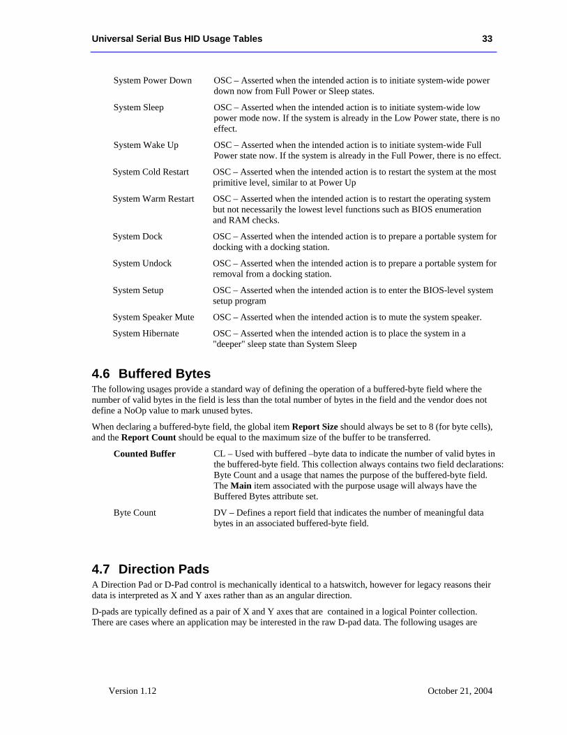
Universal Serial Bus HID Usage Tables 33
Version 1.12 October 21, 2004
System Power Down OSC – Asserted when the intended action is to initiate system-wide power down now from Full Power or Sleep states.
System Sleep OSC – Asserted when the intended action is to initiate system-wide low power mode now. If the system is already in the Low Power state, there is no effect.
System Wake Up OSC – Asserted when the intended action is to initiate system-wide Full Power state now. If the system is already in the Full Power, there is no effect.
System Cold Restart OSC – Asserted when the intended action is to restart the system at the most primitive level, similar to at Power Up
System Warm Restart OSC – Asserted when the intended action is to restart the operating system but not necessarily the lowest level functions such as BIOS enumeration and RAM checks.
System Dock OSC – Asserted when the intended action is to prepare a portable system for docking with a docking station.
System Undock OSC – Asserted when the intended action is to prepare a portable system for removal from a docking station.
System Setup OSC – Asserted when the intended action is to enter the BIOS-level system setup program
System Speaker Mute OSC – Asserted when the intended action is to mute the system speaker.
System Hibernate OSC – Asserted when the intended action is to place the system in a "deeper" sleep state than System Sleep
4.6 Buffered Bytes The following usages provide a standard way of defining the operation of a buffered-byte field where the number of valid bytes in the field is less than the total number of bytes in the field and the vendor does not define a NoOp value to mark unused bytes.
When declaring a buffered-byte field, the global item Report Size should always be set to 8 (for byte cells), and the Report Count should be equal to the maximum size of the buffer to be transferred.
Counted Buffer CL – Used with buffered –byte data to indicate the number of valid bytes in the buffered-byte field. This collection always contains two field declarations: Byte Count and a usage that names the purpose of the buffered-byte field. The Main item associated with the purpose usage will always have the Buffered Bytes attribute set.
Byte Count DV – Defines a report field that indicates the number of meaningful data bytes in an associated buffered-byte field.
4.7 Direction Pads A Direction Pad or D-Pad control is mechanically identical to a hatswitch, however for legacy reasons their data is interpreted as X and Y axes rather than as an angular direction.
D-pads are typically defined as a pair of X and Y axes that are contained in a logical Pointer collection. There are cases where an application may be interested in the raw D-pad data. The following usages are
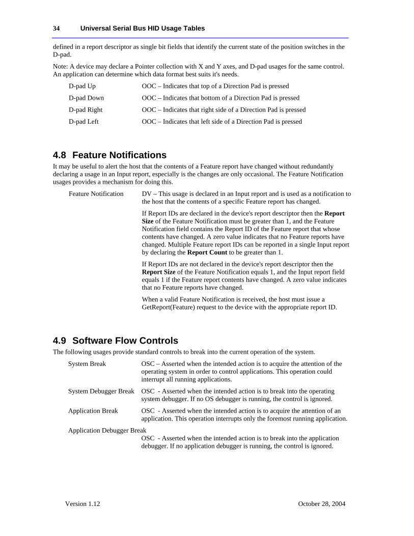
34 Universal Serial Bus HID Usage Tables
Version 1.12 October 28, 2004
defined in a report descriptor as single bit fields that identify the current state of the position switches in the D-pad.
Note: A device may declare a Pointer collection with X and Y axes, and D-pad usages for the same control. An application can determine which data format best suits it's needs.
D-pad Up OOC – Indicates that top of a Direction Pad is pressed
D-pad Down OOC – Indicates that bottom of a Direction Pad is pressed
D-pad Right OOC – Indicates that right side of a Direction Pad is pressed
D-pad Left OOC – Indicates that left side of a Direction Pad is pressed
4.8 Feature Notifications It may be useful to alert the host that the contents of a Feature report have changed without redundantly declaring a usage in an Input report, especially is the changes are only occasional. The Feature Notification usages provides a mechanism for doing this.
Feature Notification DV – This usage is declared in an Input report and is used as a notification to the host that the contents of a specific Feature report has changed.
If Report IDs are declared in the device's report descriptor then the Report Size of the Feature Notification must be greater than 1, and the Feature Notification field contains the Report ID of the Feature report that whose contents have changed. A zero value indicates that no Feature reports have changed. Multiple Feature report IDs can be reported in a single Input report by declaring the Report Count to be greater than 1.
If Report IDs are not declared in the device's report descriptor then the Report Size of the Feature Notification equals 1, and the Input report field equals 1 if the Feature report contents have changed. A zero value indicates that no Feature reports have changed.
When a valid Feature Notification is received, the host must issue a GetReport(Feature) request to the device with the appropriate report ID.
4.9 Software Flow Controls The following usages provide standard controls to break into the current operation of the system.
System Break OSC – Asserted when the intended action is to acquire the attention of the operating system in order to control applications. This operation could interrupt all running applications.
System Debugger Break OSC - Asserted when the intended action is to break into the operating system debugger. If no OS debugger is running, the control is ignored.
Application Break OSC - Asserted when the intended action is to acquire the attention of an application. This operation interrupts only the foremost running application.
Application Debugger Break OSC - Asserted when the intended action is to break into the application debugger. If no application debugger is running, the control is ignored.
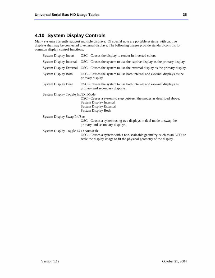
Universal Serial Bus HID Usage Tables 35
Version 1.12 October 21, 2004
4.10 System Display Controls Many systems currently support multiple displays. Of special note are portable systems with captive displays that may be connected to external displays. The following usages provide standard controls for common display control functions:
System Display Invert OSC - Causes the display to render in inverted colors.
System Display Internal OSC - Causes the system to use the captive display as the primary display.
System Display External OSC - Causes the system to use the external display as the primary display.
System Display Both OSC - Causes the system to use both internal and external displays as the primary display
System Display Dual OSC - Causes the system to use both internal and external displays as primary and secondary displays.
System Display Toggle Int/Ext Mode OSC - Causes a system to step between the modes as described above: System Display Internal System Display External System Display Both
System Display Swap Pri/Sec OSC - Causes a system using two displays in dual mode to swap the primary and secondary displays.
System Display Toggle LCD Autoscale OSC - Causes a system with a non-scaleable geometry, such as an LCD, to scale the display image to fit the physical geometry of the display.
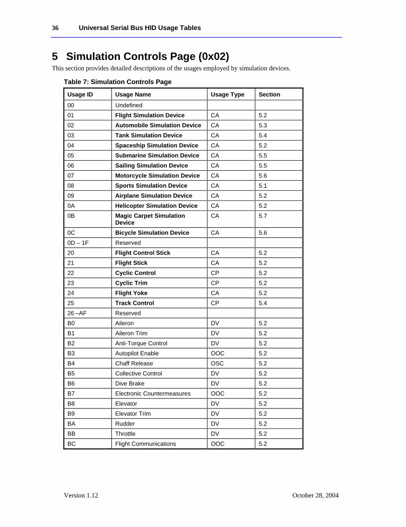
36 Universal Serial Bus HID Usage Tables
Version 1.12 October 28, 2004
5 Simulation Controls Page (0x02) This section provides detailed descriptions of the usages employed by simulation devices.
Table 7: Simulation Controls Page
Usage ID Usage Name Usage Type Section
00 Undefined
01 Flight Simulation Device CA 5.2
02 Automobile Simulation Device CA 5.3
03 Tank Simulation Device CA 5.4
04 Spaceship Simulation Device CA 5.2
05 Submarine Simulation Device CA 5.5
06 Sailing Simulation Device CA 5.5
07 Motorcycle Simulation Device CA 5.6
08 Sports Simulation Device CA 5.1
09 Airplane Simulation Device CA 5.2
0A Helicopter Simulation Device CA 5.2
0B Magic Carpet Simulation Device
CA 5.7
0C Bicycle Simulation Device CA 5.6
0D – 1F Reserved
20 Flight Control Stick CA 5.2
21 Flight Stick CA 5.2
22 Cyclic Control CP 5.2
23 Cyclic Trim CP 5.2
24 Flight Yoke CA 5.2
25 Track Control CP 5.4
26 –AF Reserved
B0 Aileron DV 5.2
B1 Aileron Trim DV 5.2
B2 Anti-Torque Control DV 5.2
B3 Autopilot Enable OOC 5.2
B4 Chaff Release OSC 5.2
B5 Collective Control DV 5.2
B6 Dive Brake DV 5.2
B7 Electronic Countermeasures OOC 5.2
B8 Elevator DV 5.2
B9 Elevator Trim DV 5.2
BA Rudder DV 5.2
BB Throttle DV 5.2
BC Flight Communications OOC 5.2
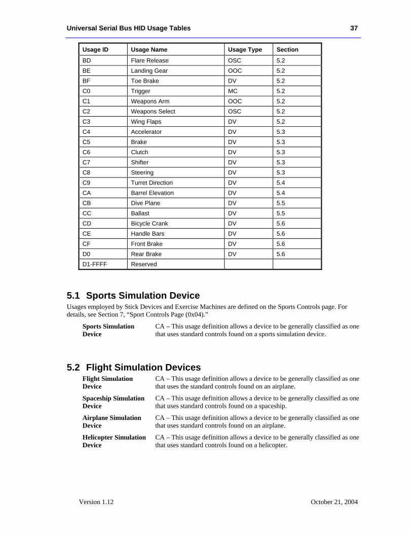
Universal Serial Bus HID Usage Tables 37
Version 1.12 October 21, 2004
Usage ID Usage Name Usage Type Section
BD Flare Release OSC 5.2
BE Landing Gear OOC 5.2
BF Toe Brake DV 5.2
C0 Trigger MC 5.2
C1 Weapons Arm OOC 5.2
C2 Weapons Select OSC 5.2
C3 Wing Flaps DV 5.2
C4 Accelerator DV 5.3
C5 Brake DV 5.3
C6 Clutch DV 5.3
C7 Shifter DV 5.3
C8 Steering DV 5.3
C9 Turret Direction DV 5.4
CA Barrel Elevation DV 5.4
CB Dive Plane DV 5.5
CC Ballast DV 5.5
CD Bicycle Crank DV 5.6
CE Handle Bars DV 5.6
CF Front Brake DV 5.6
D0 Rear Brake DV 5.6
D1-FFFF Reserved
5.1 Sports Simulation Device Usages employed by Stick Devices and Exercise Machines are defined on the Sports Controls page. For details, see Section 7, “Sport Controls Page (0x04).”
Sports Simulation Device
CA – This usage definition allows a device to be generally classified as one that uses standard controls found on a sports simulation device.
5.2 Flight Simulation Devices Flight Simulation Device
CA – This usage definition allows a device to be generally classified as one that uses the standard controls found on an airplane.
Spaceship Simulation Device
CA – This usage definition allows a device to be generally classified as one that uses standard controls found on a spaceship.
Airplane Simulation Device
CA – This usage definition allows a device to be generally classified as one that uses standard controls found on an airplane.
Helicopter Simulation Device
CA – This usage definition allows a device to be generally classified as one that uses standard controls found on a helicopter.
38 Universal Serial Bus HID Usage Tables
Version 1.12 October 28, 2004
Aileron DV – An aileron is one of two movable flaps on the wings of an airplane that can be used to control the plane’s rolling and banking movements. In the zero position the ailerons are centered, positive values will move the right aileron up and the left aileron down, and negative values will have the opposite effect on the ailerons.
Aileron Trim DV – Allows fine adjustment of the Aileron position. The zero position is the nominal position, positive values will move the right aileron up and the left aileron down, and negative values will have the opposite effect on the ailerons.
Anti-Torque Control DV – This control mechanically behaves the same as rudder pedals; as one is pushed forward, the other pushes back. In a helicopter, this controls the pitch of the tail blade to spin the helicopter in place. The zero position is centered, positive values rotate right, and negative values rotate left.
Autopilot Enable OOC – This control enables or disables an airplane’s autopilot. This should be a toggle switch, but it is typically implemented as a pushbutton.
Chaff Release OSC – Chaff is strips of metal, foil, or glass fiber with a metal content, cut into various lengths and having varying frequency responses. It is used to reflect electromagnetic energy as a radar countermeasure. These materials, usually dropped from aircraft, also can be deployed from shells or rockets. Typically this a pushbutton that initiates a release of a fixed amount of material.
Collective Control DV – This control is specifically for a helicopter. It controls the vertical acceleration or lift of the helicopter. The zero position is centered (level flight), positive values accelerate up, and negative values accelerate down.
Cyclic Control CP – This control is specifically for a helicopter. A cyclic control is a stick between the pilot’s legs that moves in two axes. It controls the swash plate, which in turn controls horizontal acceleration of the helicopter. The zero position is centered, positive Y values accelerate forward, and negative Y values accelerate backward. Positive X values accelerate right, and negative X values accelerate left. This collection will contain X and Y axes.
Cyclic Trim CP – This control is specifically for a helicopter. Cyclic Trim allows fine adjustment of the cyclic position in two dimensions. The zero position is the nominal position, positive values adjust the baseline acceleration right or forward, and negative values adjust the baseline acceleration left or backward, respectively. This collection will contain X and Y axes.
Dive Brake DV – A flap that can be extended on an aircraft to increase drag and reduce the speed of descent. It is typically implemented as a lever that generates a dimensionless value between no braking (0) and full braking.
Electronic Countermeasures
OOC – A pushbutton that enables electronic countermeasures. This is typically active radar jamming; however Chaff (radar) or Flare (infrared) can be invoked.
Elevator DV – A movable control surface, usually attached to the horizontal stabilizer of an aircraft, that is used to produce motion up or down. The zero position is centered, positive values raise the elevator, and negative values lower the elevator.
Universal Serial Bus HID Usage Tables 39
Version 1.12 October 21, 2004
Elevator Trim DV – Elevator Trim allows fine adjustment of the Elevator position. The zero position is the nominal position, positive values are elevator offset up, and negative values are elevator offset down.
Flight Communications OOC – In combat aircraft, a communication (comm) button is usually positioned under the index finger. Typically this is a two-position pushbutton where the first position enables communications with the crew and the second position enables the transmitter for communication external to the plane.
Flare Release OSC – A flare is a device that produces a bright light for signaling, illumination, identification, or heat for infrared missile countermeasures. Typically this is a pushbutton that releases a fixed number of flares.
Flight Control Stick CA – A Flight Control Stick controls the Pitch and Roll of an airplane. It looks like a joystick. The stick may be pushed forward or pulled back to move the tail elevator down or up, respectively. Pushing forward causes the plane to nose down. Tilting the stick right and left alters the position of the ailerons. In the zero position the ailerons are centered, tilting the stick to the right will move the right aileron up and the left aileron down, and tilting the stick to the left direction will have the opposite effect on the ailerons.
Mechanically, a stick presents two degrees of rotational freedom with approximately a +/–45° range. However, these axes are represented as Generic Desktop Page translational axes X (Roll) and Y (Pitch).
Flight Stick CA – A Flight Stick defines a class of device commonly used for flight simulator games. For a device to qualify as a Flight Stick, it must support at least two axes (Pitch and Roll), a trigger button, three additional buttons, and a hat switch. A Flight Stick is a functional subset of a Flight Control Stick.
Landing Gear OOC – A control for raising or lowering an airplane’s landing gear. This should be a toggle switch, but it is typically implemented as pushbutton.
Rudder DV – The zero position is centered, positive values turn right, and negative values turn left.
Toe Brake DV – A device for slowing or stopping the motion of an airplane when it is on the ground. Typically, Toe Brakes consist of two foot pedals that affect the left and right brakes, respectively. Control of the Toe Brakes can allow steering of the plane as well as braking when it is on the ground. An analog Toe Brake generates a dimensionless value between 0 and full scale. In some implementations, the Toe Brake can simply be a pushbutton (full on or off).
Throttle DV – A valve that regulates the flow of a fluid, such as the valve in an internal-combustion engine that controls the amount of vaporized fuel entering the cylinders. A lever or pedal controlling such a valve generates a dimensionless value between 0 and full scale.
Trigger MC – A lever pressed by the finger to release or activate a mechanism, typically used to discharge a firearm. However, a Trigger can be used for many devices. In combat airplanes the Trigger is usually positioned under the thumb; for a gun it would be positioned under the index finger. Typically this is implemented as a pushbutton.
Weapons Arm OOC – This device is normally a covered toggle switch that must be selected to enable the weapons system.

40 Universal Serial Bus HID Usage Tables
Version 1.12 October 28, 2004
Weapons Select OSC – This device can either be a pushbutton that steps through the available weapons or a radio button that selects them individually.
Wing Flaps DV – Wing flap controls are usually powered either hydraulically or by electric motors, and are used for low-speed control of an airplane. A flap generates a value between 0 and full extension.
Flight Yoke CA – A flight yoke (also called a control wheel) controls the pitch and roll of an airplane. It looks like a bow tie grasped by both hands. The yoke at which the pilot sits may be pushed forward or pulled back to move the tail elevator down or up, respectively. In the zero position the elevator is centered for level flight. Pushing forward on the yoke causes the plane to nose down and generates negative values. Pulling back on the yoke causes the plane to nose up and generates positive values.
Rotating the yoke alters the position of the ailerons. In the zero position the ailerons are centered. Rotating the yoke in a clockwise direction will move the right aileron up and the left aileron down and generate incrementing values. Rotating the yoke in the counterclockwise direction will have the opposite effect on the ailerons and generate decrementing values.
5.3 Automobile Simulation Devices
Automobile Simulation Device
CA – This usage definition allows a device to be generally classified as one that uses the standard controls found in an automobile or truck.
Accelerator DV – A device, especially the gas pedal of a motor vehicle, for increasing speed. An Accelerator is a dimensionless single degree-of-freedom dynamic value, where the range of values is from zero to maximum acceleration.
Brake DV – A device for slowing or stopping motion, as of a vehicle, especially by contact friction. A Brake can be an On/Off Control or a dimensionless single degree-of-freedom dynamic value, where the range of values is from zero to maximum braking.
Clutch DV – A device for disengaging the transmission of a vehicle to allow shifting of gears. A Clutch can be a generic button or a dimensionless single degree-of-freedom dynamic value, where the range of values is from zero to maximum clutch actuation.
Shifter DV – A device for shifting gears in a vehicle. A Shifter is a specialized mechanical configuration of a radio button. A zero value is returned when the shifter is in the neutral position. Positive values indicate the forward gear and negative values indicate the reverse gear that the device is in.
Steering DV – A steering wheel is a single degree-of-freedom device that rotates about an axis. The zero position is always the neutral or “straight ahead” position, with positive values turning clockwise and negative values turning counterclockwise. If the Coordinate Values Wrap attribute is set, the steering wheel can be turned past 360 degrees.
Universal Serial Bus HID Usage Tables 41
Version 1.12 October 21, 2004
5.4 Tank Simulation Devices
Tank Simulation Device
CA – This usage definition allows a device to be generally classified as one that uses standard controls found in a tank or a treaded vehicle.
Track Control CP – A device for controlling the direction and velocity of a vehicle that is driven by tracks. There can be either two sticks with one degree of freedom or a single stick with two degrees of freedom:
In the two-stick case, the neutral position is when the stick is centered (zero). Pushing the stick forward causes forward acceleration (positive values), and pulling it back causes reverse acceleration (negative values). The righthand and lefthand controls will affect the corresponding side of the vehicle.
In the one-stick case, forward/backward acceleration works the same as in the two-stick case. However, right or left movement of the stick determines the amount of power applied to the respective track. When the stick is centered horizontally, equal amounts of power are applied to both tracks, generating a zero output value. Moving the stick to the right will generate positive values, and moving the stick to the left will generate negative values. A Tank Track Control is a dimensionless analog entity.
Turret Direction DV – This control determines the right-to-left positioning of the tank turret. A value of zero maintains the current orientation of the turret. A positive value turns the turret to the right and a negative value turns the turret to the left.
Barrel Elevation DV – This control determines the elevation of the gun barrel in a turret. A value of zero maintains the current orientation of the barrel. A positive value raises the barrel and a negative value lowers the barrel.
5.5 Maritime Simulation Devices
Submarine Simulation Device
CA – Allows a device to be generally classified as one that uses the standard controls of a submarine.
Dive Plane DV – Dive planes control the vertical ascent or descent of the submarine under power. A zero value indicates level travel. Positive values indicate ascent, and negative values indicate descent. A Dive Plane is a dimensionless analog entity.
Ballast DV – Ballast controls the vertical ascent or descent of the submarine. A zero value indicates level travel. Positive values indicate ascent, and negative values indicate descent. A Ballast is a dimensionless analog entity.
Sailing Simulation Device
CA – Allows a device to be generally classified as one that uses the standard controls of a sailboat.
42 Universal Serial Bus HID Usage Tables
Version 1.12 October 28, 2004
5.6 Two-wheeled Simulation Devices
Motorcycle Simulation Device
CA – Allows a device to be generally classified as one that uses the standard controls of a motorcycle.
Bicycle Simulation Device
CA – Allows a device to be generally classified as one that uses the standard controls of a bicycle.
Bicycle Crank DV – A foot-operated assembly of pedals attached to a crank that is used for powering a bicycle. The reported value is the rate that the crank turns per minute.
Handle Bars DV – A steering control, held in both hands, for a motorcycle or bicycle. A zero output value indicates that the direction of travel is straight ahead. Pulling back on the right side turns the vehicle to the right and generates a positive output. Pulling back on the left side turns the vehicle to the left and generates a negative output.
Front Brake DV – Engages the front brake of the motorcycle to slow the vehicle. A Front Brake can be a generic button or a dimensionless single degree-of-freedom analog entity, where the range of values is from zero to maximum braking.
Rear Brake DV– Engages the rear brake of the motorcycle to slow the vehicle. A Rear Brake can be a generic button or a dimensionless single degree-of-freedom analog entity, where the range of values is from zero to maximum braking.
5.7 Miscellaneous Simulation Devices
Magic Carpet Simulation Device
CA – Allows a device to be generally classified as one that uses the standard control of a magic carpet. This control is a bar, grasped by both hands, that controls the Yaw, Pitch and Roll of the carpet.
The bar, at which the pilot sits, may be pushed forward or pulled back to cause the carpet to dive or rise, respectively. In the zero position, the carpet is in level flight. Pushing forward on the bar causes the carpet to nose down and generates negative values. Pulling back on the bar causes the carpet to nose up and generates positive values.
Turning the bar turns the carpet. In the zero position, the carpet travels straight ahead. Pulling back on the right side turns the carpet to the right and generates positive values. Pulling back on the left side turns the carpet to the left and generates negative values.
Rotating the bar rolls the carpet. In the zero position, the carpet travels level. Rotating the bar in a clockwise direction rolls the carpet to the right and generates positive values. Rotating the bar in the counterclockwise direction rolls the carpet to the left and generates negative values.
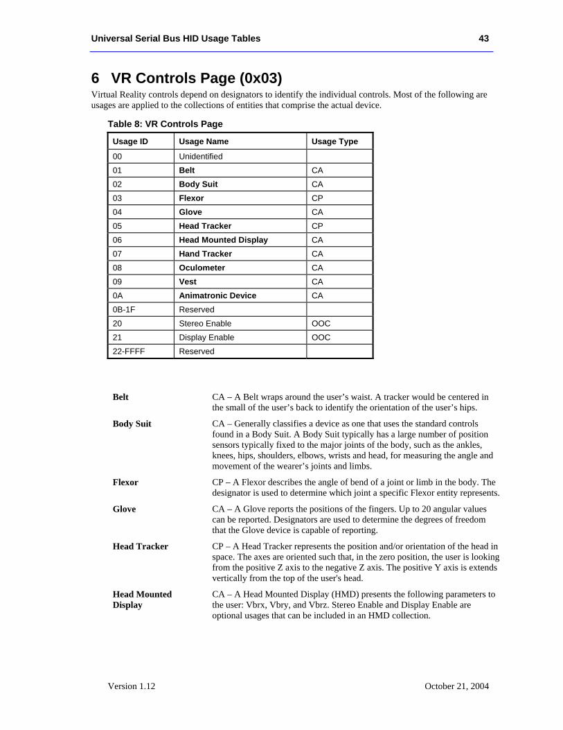
Universal Serial Bus HID Usage Tables 43
Version 1.12 October 21, 2004
6 VR Controls Page (0x03) Virtual Reality controls depend on designators to identify the individual controls. Most of the following are usages are applied to the collections of entities that comprise the actual device.
Table 8: VR Controls Page
Usage ID Usage Name Usage Type
00 Unidentified
01 Belt CA
02 Body Suit CA
03 Flexor CP
04 Glove CA
05 Head Tracker CP
06 Head Mounted Display CA
07 Hand Tracker CA
08 Oculometer CA
09 Vest CA
0A Animatronic Device CA
0B-1F Reserved
20 Stereo Enable OOC
21 Display Enable OOC
22-FFFF Reserved
Belt CA – A Belt wraps around the user’s waist. A tracker would be centered in the small of the user’s back to identify the orientation of the user’s hips.
Body Suit CA – Generally classifies a device as one that uses the standard controls found in a Body Suit. A Body Suit typically has a large number of position sensors typically fixed to the major joints of the body, such as the ankles, knees, hips, shoulders, elbows, wrists and head, for measuring the angle and movement of the wearer’s joints and limbs.
Flexor CP – A Flexor describes the angle of bend of a joint or limb in the body. The designator is used to determine which joint a specific Flexor entity represents.
Glove CA – A Glove reports the positions of the fingers. Up to 20 angular values can be reported. Designators are used to determine the degrees of freedom that the Glove device is capable of reporting.
Head Tracker CP – A Head Tracker represents the position and/or orientation of the head in space. The axes are oriented such that, in the zero position, the user is looking from the positive Z axis to the negative Z axis. The positive Y axis is extends vertically from the top of the user's head.
Head Mounted Display
CA – A Head Mounted Display (HMD) presents the following parameters to the user: Vbrx, Vbry, and Vbrz. Stereo Enable and Display Enable are optional usages that can be included in an HMD collection.
44 Universal Serial Bus HID Usage Tables
Version 1.12 October 28, 2004
Stereo Enable OOC – Selects the display mode of the HMD. A value of 0 selects monoscopic mode and 1 selects stereoscopic mode.
Display Enable OOC – Enables the HMD video output. A value of 0 turns off the display and 1 turns it on.
Hand Tracker CA – A Hand Tracker represents the position of the hand in space. A Hand Tracker attaches to the back of the hand. In the zero position, it is assumed that the hand is held upright with the extended thumb parallel to the Y axis and the fingers pointing in the negative Z direction
Oculometer CA – An Oculometer identifies the direction in which the eye is looking in rotation about the X and Y axes. The designator for an Oculometer is always Eye.
Vest CA – A Vest wraps around the user’s chest and abdomen. A tracker would be placed on the user’s back between the shoulder blades.
Animatronic Device CA – An input device for the animation of mechanical or Computer Graphic Image “electronic” puppets. An animatronic device is engineered to fit a puppeteer’s or performer’s body (and/or head and/or face) and comfortably allow a wide range of physical freedom.
An Animatronic Device measures the angle and movement of the wearer’s joints and limbs, which are then translated into the motion of a puppet, allowing the puppet to mimic the wearer’s movements. There is not necessarily a 1:1 mapping of human to puppet controls. A puppeteer’s arm may be used to control the movement of an elephant’s trunk, or hand controls may be used to control facial expressions. Designators are used to determine which puppeteer joint is being tracked. The controlling application will map these inputs to the electronic or mechanical device.
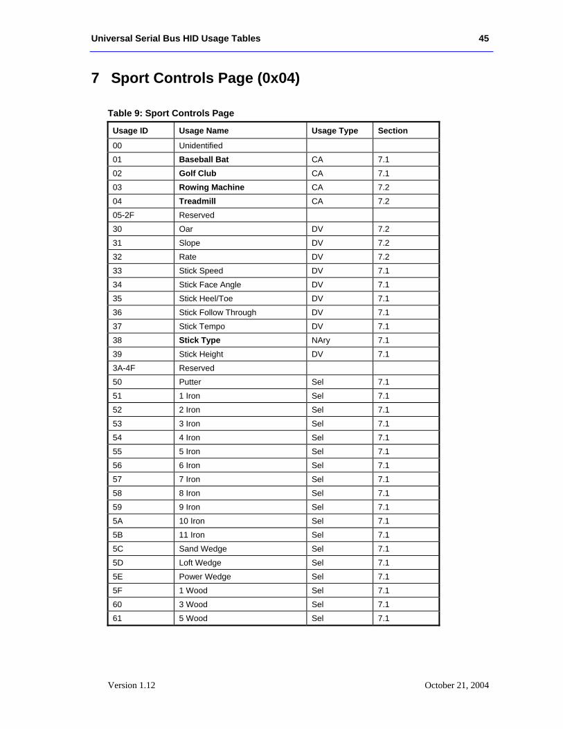
Universal Serial Bus HID Usage Tables 45
Version 1.12 October 21, 2004
7 Sport Controls Page (0x04)
Table 9: Sport Controls Page
Usage ID Usage Name Usage Type Section
00 Unidentified
01 Baseball Bat CA 7.1
02 Golf Club CA 7.1
03 Rowing Machine CA 7.2
04 Treadmill CA 7.2
05-2F Reserved
30 Oar DV 7.2
31 Slope DV 7.2
32 Rate DV 7.2
33 Stick Speed DV 7.1
34 Stick Face Angle DV 7.1
35 Stick Heel/Toe DV 7.1
36 Stick Follow Through DV 7.1
37 Stick Tempo DV 7.1
38 Stick Type NAry 7.1
39 Stick Height DV 7.1
3A-4F Reserved
50 Putter Sel 7.1
51 1 Iron Sel 7.1
52 2 Iron Sel 7.1
53 3 Iron Sel 7.1
54 4 Iron Sel 7.1
55 5 Iron Sel 7.1
56 6 Iron Sel 7.1
57 7 Iron Sel 7.1
58 8 Iron Sel 7.1
59 9 Iron Sel 7.1
5A 10 Iron Sel 7.1
5B 11 Iron Sel 7.1
5C Sand Wedge Sel 7.1
5D Loft Wedge Sel 7.1
5E Power Wedge Sel 7.1
5F 1 Wood Sel 7.1
60 3 Wood Sel 7.1
61 5 Wood Sel 7.1
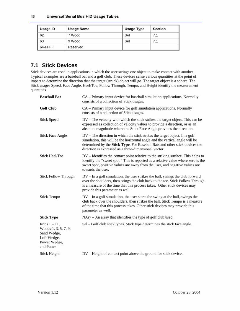
46 Universal Serial Bus HID Usage Tables
Version 1.12 October 28, 2004
Usage ID Usage Name Usage Type Section
62 7 Wood Sel 7.1
63 9 Wood Sel 7.1
64-FFFF Reserved
7.1 Stick Devices Stick devices are used in applications in which the user swings one object to make contact with another. Typical examples are a baseball bat and a golf club. These devices sense various quantities at the point of impact to determine the direction that the target (struck) object will go. The target object is a sphere. The Stick usages Speed, Face Angle, Heel/Toe, Follow Through, Tempo, and Height identify the measurement quantities.
Baseball Bat CA – Primary input device for baseball simulation applications. Normally consists of a collection of Stick usages.
Golf Club CA – Primary input device for golf simulation applications. Normally consists of a collection of Stick usages.
Stick Speed DV – The velocity with which the stick strikes the target object. This can be expressed as collection of velocity values to provide a direction, or as an absolute magnitude where the Stick Face Angle provides the direction.
Stick Face Angle DV – The direction in which the stick strikes the target object. In a golf simulation, this will be the horizontal angle and the vertical angle will be determined by the Stick Type. For Baseball Bats and other stick devices the direction is expressed as a three-dimensional vector.
Stick Heel/Toe DV – Identifies the contact point relative to the striking surface. This helps to identify the “sweet spot.” This is reported as a relative value where zero is the sweet spot, positive values are away from the user, and negative values are towards the user.
Stick Follow Through DV – In a golf simulation, the user strikes the ball, swings the club forward over the shoulders, then brings the club back to the tee. Stick Follow Through is a measure of the time that this process takes. Other stick devices may provide this parameter as well.
Stick Tempo DV – In a golf simulation, the user starts the swing at the ball, swings the club back over the shoulders, then strikes the ball. Stick Tempo is a measure of the time that this process takes. Other stick devices may provide this parameter as well.
Stick Type NAry – An array that identifies the type of golf club used.
Irons 1 – 11, Woods 1, 3, 5, 7, 9, Sand Wedge, Loft Wedge, Power Wedge, and Putter
Sel – Golf club stick types. Stick type determines the stick face angle.
Stick Height DV – Height of contact point above the ground for stick device.
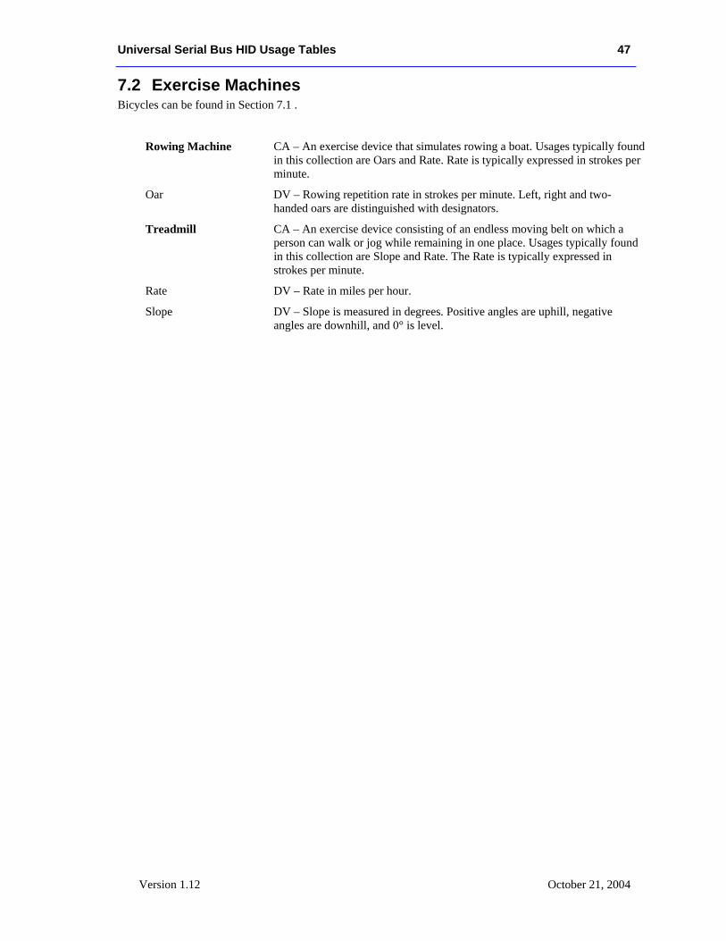
Universal Serial Bus HID Usage Tables 47
Version 1.12 October 21, 2004
7.2 Exercise Machines Bicycles can be found in Section 7.1 .
Rowing Machine CA – An exercise device that simulates rowing a boat. Usages typically found in this collection are Oars and Rate. Rate is typically expressed in strokes per minute.
Oar DV – Rowing repetition rate in strokes per minute. Left, right and two-handed oars are distinguished with designators.
Treadmill CA – An exercise device consisting of an endless moving belt on which a person can walk or jog while remaining in one place. Usages typically found in this collection are Slope and Rate. The Rate is typically expressed in strokes per minute.
Rate DV – Rate in miles per hour.
Slope DV – Slope is measured in degrees. Positive angles are uphill, negative angles are downhill, and 0° is level.
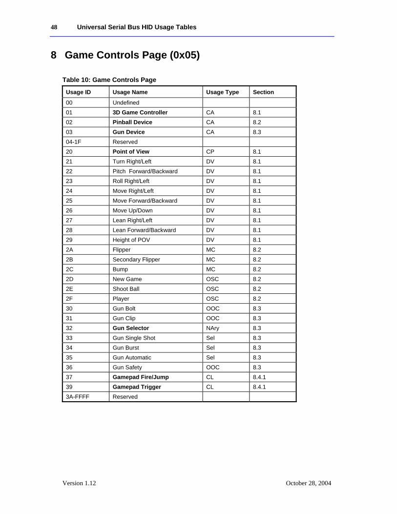
48 Universal Serial Bus HID Usage Tables
Version 1.12 October 28, 2004
8 Game Controls Page (0x05)
Table 10: Game Controls Page
Usage ID Usage Name Usage Type Section
00 Undefined
01 3D Game Controller CA 8.1
02 Pinball Device CA 8.2
03 Gun Device CA 8.3
04-1F Reserved
20 Point of View CP 8.1
21 Turn Right/Left DV 8.1
22 Pitch Forward/Backward DV 8.1
23 Roll Right/Left DV 8.1
24 Move Right/Left DV 8.1
25 Move Forward/Backward DV 8.1
26 Move Up/Down DV 8.1
27 Lean Right/Left DV 8.1
28 Lean Forward/Backward DV 8.1
29 Height of POV DV 8.1
2A Flipper MC 8.2
2B Secondary Flipper MC 8.2
2C Bump MC 8.2
2D New Game OSC 8.2
2E Shoot Ball OSC 8.2
2F Player OSC 8.2
30 Gun Bolt OOC 8.3
31 Gun Clip OOC 8.3
32 Gun Selector NAry 8.3
33 Gun Single Shot Sel 8.3
34 Gun Burst Sel 8.3
35 Gun Automatic Sel 8.3
36 Gun Safety OOC 8.3
37 Gamepad Fire/Jump CL 8.4.1
39 Gamepad Trigger CL 8.4.1
3A-FFFF Reserved
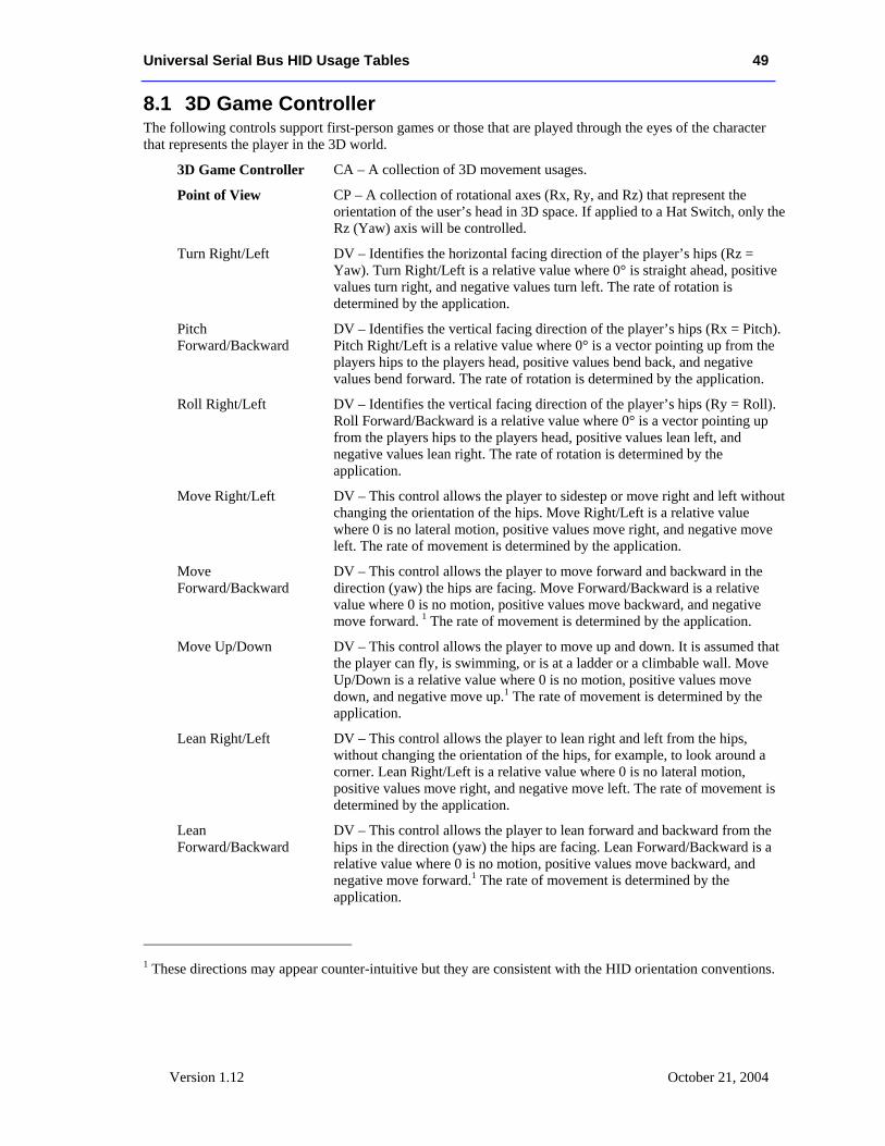
Universal Serial Bus HID Usage Tables 49
Version 1.12 October 21, 2004
8.1 3D Game Controller The following controls support first-person games or those that are played through the eyes of the character that represents the player in the 3D world.
3D Game Controller CA – A collection of 3D movement usages.
Point of View CP – A collection of rotational axes (Rx, Ry, and Rz) that represent the orientation of the user’s head in 3D space. If applied to a Hat Switch, only the Rz (Yaw) axis will be controlled.
Turn Right/Left DV – Identifies the horizontal facing direction of the player’s hips (Rz = Yaw). Turn Right/Left is a relative value where 0° is straight ahead, positive values turn right, and negative values turn left. The rate of rotation is determined by the application.
Pitch Forward/Backward
DV – Identifies the vertical facing direction of the player’s hips (Rx = Pitch). Pitch Right/Left is a relative value where 0° is a vector pointing up from the players hips to the players head, positive values bend back, and negative values bend forward. The rate of rotation is determined by the application.
Roll Right/Left DV – Identifies the vertical facing direction of the player’s hips (Ry = Roll). Roll Forward/Backward is a relative value where 0° is a vector pointing up from the players hips to the players head, positive values lean left, and negative values lean right. The rate of rotation is determined by the application.
Move Right/Left DV – This control allows the player to sidestep or move right and left without changing the orientation of the hips. Move Right/Left is a relative value where 0 is no lateral motion, positive values move right, and negative move left. The rate of movement is determined by the application.
Move Forward/Backward
DV – This control allows the player to move forward and backward in the direction (yaw) the hips are facing. Move Forward/Backward is a relative value where 0 is no motion, positive values move backward, and negative move forward. 1 The rate of movement is determined by the application.
Move Up/Down DV – This control allows the player to move up and down. It is assumed that the player can fly, is swimming, or is at a ladder or a climbable wall. Move Up/Down is a relative value where 0 is no motion, positive values move down, and negative move up.1 The rate of movement is determined by the application.
Lean Right/Left DV – This control allows the player to lean right and left from the hips, without changing the orientation of the hips, for example, to look around a corner. Lean Right/Left is a relative value where 0 is no lateral motion, positive values move right, and negative move left. The rate of movement is determined by the application.
Lean Forward/Backward
DV – This control allows the player to lean forward and backward from the hips in the direction (yaw) the hips are facing. Lean Forward/Backward is a relative value where 0 is no motion, positive values move backward, and negative move forward.1 The rate of movement is determined by the application.
1 These directions may appear counter-intuitive but they are consistent with the HID orientation conventions.
50 Universal Serial Bus HID Usage Tables
Version 1.12 October 28, 2004
Height of POV DV – This control allows the player to stand, squat, and crawl. Height of POV is a relative value where 0 is the normal standing position and positive values lower the player’s Point Of View. The maximum value as indicated by Logical Maximum is the crawling position, the median positive value is the squatting position, and negative values indicate the player is standing on tiptoes or flying. 1
8.2 Pinball Device Pinball is a game played on a device in which the player operates a plunger to shoot a ball down or along a slanted surface that has obstacles and targets.
Pinball Device CA – A collection of usages representing the controls of a pinball game.
Flipper MC – A button that actuates a bar that swings around a pivot to change the direction of the ball. A pair of right and left flippers normally resides at the near end of the table.
Secondary Flipper MC – A button that actuates a bar that swings around a pivot to change the direction of the ball. Secondary flippers normally reside on the sides halfway up the table.
Bump MC – A control that indicates that the flipper assembly has been shoved by the player to change the direction of the ball. This can be as simple as a switch or as complex as a 3D force vector.
New Game OSC – A button that terminates any current game and reinitializes for a new game.
Shoot Ball OSC – A control that indicates that the player has placed the ball into play. This can be as a switch or a force vector.
Player OSC – A button that cycles through the number of players supported by the game.
8.3 Gun Device A Gun Device is used in battle and war game simulations.
Gun Device CA – A collection of Gun usages that describes a hand-held projectile weapon.
Gun Bolt OOC – A control that indicates the state of the gun bolt. A value of 1 indicates that the bolt is locked and ready to fire, and 0 indicates that the bolt is open, ready for the next shell.
Gun Clip OOC – A control that indicates whether the gun clip is inserted. A value of 1 indicates that the clip is inserted, and 0 indicates that the clip is missing.
Gun Selector NAry – This control identifies the firing mode of the weapon. Typically it is a mutually exclusive set of usages for single shot, burst, and fully automatic firing that are presented as an array input.
Gun Single Shot Sel – Selects a single shot each time the trigger is pulled.
Universal Serial Bus HID Usage Tables 51
Version 1.12 October 21, 2004
Gun Burst Sel – Selects a short burst (three shots) each time the trigger is pulled.
Gun Automatic Sel – Places the gun in fully automatic mode where it will fire continuously while the trigger is pulled.
Gun Safety OOC – A control that indicates whether safety is enabled. A value of 1 indicates that the gun is enabled to fire, and 0 indicates that gun will not fire when the trigger is pulled.
8.4 Gamepads The following Usages are targeted at gamepads however they can be used for any devices.
Gamepads use Start and Select buttons allow simple menu control. Select allows auser to linearly step through application options. If an option can be varied (i.e. volume, game speed, etc.) then the D-pad is typically used to modify it's value. A user indicates the final acceptance of an option by pressing Start. Seethe Generic Desktop page for the Start and Select button usage definitions.
Gamepad recommendations
1) All gamepad controls should have associated Physical descriptors.
2) If a gamepad control is labeled an associated String descriptor should be declared.
8.4.1 Gamepad Button Collections Usages in the Gamepad Button Collections are assigned from the Button Page where Button 1 is the easiest for the user to access. Ideally, Button 1 is under the users finger when it is at rest. Button 2 is the next easiest to access and so on. The default gamepad is assumed to have the D-pad under the users left thumb and the Fire/Jump buttons under the right thumb.
The individual Gamepad Button collections can also support "chorded" commands. A Chorded command is invoked by simultaneously pressing multiple buttons with multiple fingers. By separating the buttons into thumb and index finger groups it will be possible for an application to identify whether a gamepad can support chorded commands.
An application should assume that if more than one button is pressed (true) in a collection that only the first button pressed is true. Or the lowest Button (Usage ID) is pressed if two or more buttons in the same collection become true in the same report.
Gamepad Fire/Jump and Trigger buttons are defined with the following conventions: Button 0 is the primary (or easiest to access) button, Button 1 is the secondary button, Button 3 is the tertiary button, and so on. Designators can be applied if more detail is required.
Gamepad Fire/Jump CL – A collection of gamepad buttons controlled by the user's thumb.
Gamepad Trigger CL – A collection of gamepad buttons controlled by the user's index fingers.
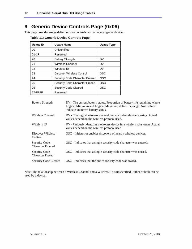
52 Universal Serial Bus HID Usage Tables
Version 1.12 October 28, 2004
9 Generic Device Controls Page (0x06) This page provides usage definitions for controls can be on any type of device.
Table 11: Generic Device Controls Page
Usage ID Usage Name Usage Type
00 Unidentified
01-1F Reserved
20 Battery Strength DV
21 Wireless Channel DV
22 Wireless ID DV
23 Discover Wireless Control OSC
24 Security Code Character Entered OSC
25 Security Code Character Erased OSC
26 Security Code Cleared OSC
27-FFFF Reserved
Battery Strength DV - The current battery status. Proportion of battery life remaining where Logical Minimum and Logical Maximum define the range. Null values indicate unknown battery status.
Wireless Channel DV - The logical wireless channel that a wireless device is using. Actual values depend on the wireless protocol used.
Wireless ID DV - Uniquely identifies a wireless device in a wireless subsystem. Actual values depend on the wireless protocol used.
Discover Wireless Control
OSC - Initiates or enables discovery of nearby wireless devices.
Security Code Character Entered
OSC - Indicates that a single security code character was entered.
Security Code Character Erased
OSC - Indicates that a single security code character was erased.
Security Code Cleared OSC - Indicates that the entire security code was erased.
Note: The relationship between a Wireless Channel and a Wireless ID is unspecified. Either or both can be used by a device.
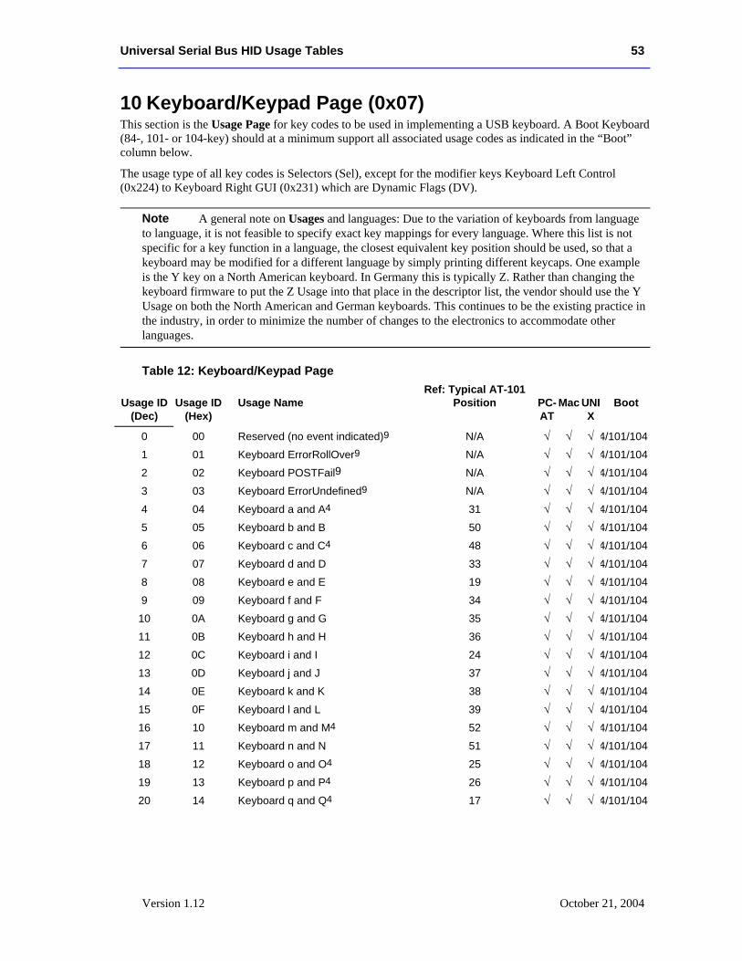
Universal Serial Bus HID Usage Tables 53
Version 1.12 October 21, 2004
10 Keyboard/Keypad Page (0x07) This section is the Usage Page for key codes to be used in implementing a USB keyboard. A Boot Keyboard (84-, 101- or 104-key) should at a minimum support all associated usage codes as indicated in the “Boot” column below.
The usage type of all key codes is Selectors (Sel), except for the modifier keys Keyboard Left Control (0x224) to Keyboard Right GUI (0x231) which are Dynamic Flags (DV).
A general note on Usages and languages: Due to the variation of keyboards from language to language, it is not feasible to specify exact key mappings for every language. Where this list is not specific for a key function in a language, the closest equivalent key position should be used, so that a keyboard may be modified for a different language by simply printing different keycaps. One example is the Y key on a North American keyboard. In Germany this is typically Z. Rather than changing the keyboard firmware to put the Z Usage into that place in the descriptor list, the vendor should use the Y Usage on both the North American and German keyboards. This continues to be the existing practice in the industry, in order to minimize the number of changes to the electronics to accommodate other languages.
Table 12: Keyboard/Keypad Page
Usage ID (Dec)
Usage ID
(Hex)
Usage Name
Ref: Typical AT-101 Position
PC-AT
Mac
UNIX
Boot
0 00 Reserved (no event indicated)9 N/A √ √ √ 4/101/104
1 01 Keyboard ErrorRollOver9 N/A √ √ √ 4/101/104
2 02 Keyboard POSTFail9 N/A √ √ √ 4/101/104
3 03 Keyboard ErrorUndefined9 N/A √ √ √ 4/101/104
4 04 Keyboard a and A4 31 √ √ √ 4/101/104
5 05 Keyboard b and B 50 √ √ √ 4/101/104
6 06 Keyboard c and C4 48 √ √ √ 4/101/104
7 07 Keyboard d and D 33 √ √ √ 4/101/104
8 08 Keyboard e and E 19 √ √ √ 4/101/104
9 09 Keyboard f and F 34 √ √ √ 4/101/104
10 0A Keyboard g and G 35 √ √ √ 4/101/104
11 0B Keyboard h and H 36 √ √ √ 4/101/104
12 0C Keyboard i and I 24 √ √ √ 4/101/104
13 0D Keyboard j and J 37 √ √ √ 4/101/104
14 0E Keyboard k and K 38 √ √ √ 4/101/104
15 0F Keyboard l and L 39 √ √ √ 4/101/104
16 10 Keyboard m and M4 52 √ √ √ 4/101/104
17 11 Keyboard n and N 51 √ √ √ 4/101/104
18 12 Keyboard o and O4 25 √ √ √ 4/101/104
19 13 Keyboard p and P4 26 √ √ √ 4/101/104
20 14 Keyboard q and Q4 17 √ √ √ 4/101/104
Note
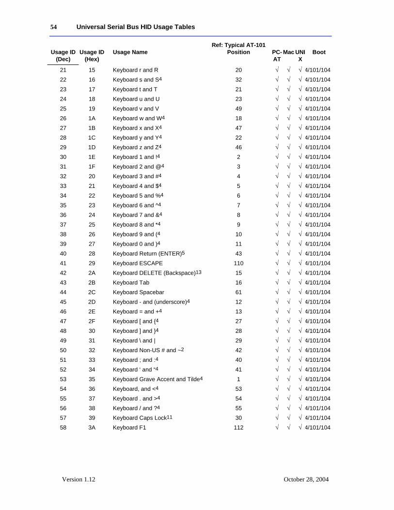
54 Universal Serial Bus HID Usage Tables
Version 1.12 October 28, 2004
Usage ID
(Dec)
Usage ID
(Hex)
Usage Name
Ref: Typical AT-101 Position
PC-AT
Mac
UNIX
Boot
21 15 Keyboard r and R 20 √ √ √ 4/101/104
22 16 Keyboard s and S4 32 √ √ √ 4/101/104
23 17 Keyboard t and T 21 √ √ √ 4/101/104
24 18 Keyboard u and U 23 √ √ √ 4/101/104
25 19 Keyboard v and V 49 √ √ √ 4/101/104
26 1A Keyboard w and W4 18 √ √ √ 4/101/104
27 1B Keyboard x and X4 47 √ √ √ 4/101/104
28 1C Keyboard y and Y4 22 √ √ √ 4/101/104
29 1D Keyboard z and Z4 46 √ √ √ 4/101/104
30 1E Keyboard 1 and !4 2 √ √ √ 4/101/104
31 1F Keyboard 2 and @4 3 √ √ √ 4/101/104
32 20 Keyboard 3 and #4 4 √ √ √ 4/101/104
33 21 Keyboard 4 and $4 5 √ √ √ 4/101/104
34 22 Keyboard 5 and %4 6 √ √ √ 4/101/104
35 23 Keyboard 6 and ^4 7 √ √ √ 4/101/104
36 24 Keyboard 7 and &4 8 √ √ √ 4/101/104
37 25 Keyboard 8 and *4 9 √ √ √ 4/101/104
38 26 Keyboard 9 and (4 10 √ √ √ 4/101/104
39 27 Keyboard 0 and )4 11 √ √ √ 4/101/104
40 28 Keyboard Return (ENTER)5 43 √ √ √ 4/101/104
41 29 Keyboard ESCAPE 110 √ √ √ 4/101/104
42 2A Keyboard DELETE (Backspace)13 15 √ √ √ 4/101/104
43 2B Keyboard Tab 16 √ √ √ 4/101/104
44 2C Keyboard Spacebar 61 √ √ √ 4/101/104
45 2D Keyboard - and (underscore)4 12 √ √ √ 4/101/104
46 2E Keyboard = and +4 13 √ √ √ 4/101/104
47 2F Keyboard [ and {4 27 √ √ √ 4/101/104
48 30 Keyboard ] and }4 28 √ √ √ 4/101/104
49 31 Keyboard \ and | 29 √ √ √ 4/101/104
50 32 Keyboard Non-US # and ~2 42 √ √ √ 4/101/104
51 33 Keyboard ; and :4 40 √ √ √ 4/101/104
52 34 Keyboard ‘ and “4 41 √ √ √ 4/101/104
53 35 Keyboard Grave Accent and Tilde4 1 √ √ √ 4/101/104
54 36 Keyboard, and <4 53 √ √ √ 4/101/104
55 37 Keyboard . and >4 54 √ √ √ 4/101/104
56 38 Keyboard / and ?4 55 √ √ √ 4/101/104
57 39 Keyboard Caps Lock11 30 √ √ √ 4/101/104
58 3A Keyboard F1 112 √ √ √ 4/101/104
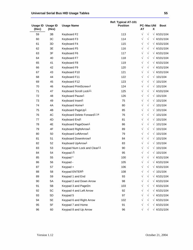
Universal Serial Bus HID Usage Tables 55
Version 1.12 October 21, 2004
Usage ID
(Dec)
Usage ID
(Hex)
Usage Name
Ref: Typical AT-101 Position
PC-AT
Mac
UNIX
Boot
59 3B Keyboard F2 113 √ √ √ 4/101/104
60 3C Keyboard F3 114 √ √ √ 4/101/104
61 3D Keyboard F4 115 √ √ √ 4/101/104
62 3E Keyboard F5 116 √ √ √ 4/101/104
63 3F Keyboard F6 117 √ √ √ 4/101/104
64 40 Keyboard F7 118 √ √ √ 4/101/104
65 41 Keyboard F8 119 √ √ √ 4/101/104
66 42 Keyboard F9 120 √ √ √ 4/101/104
67 43 Keyboard F10 121 √ √ √ 4/101/104
68 44 Keyboard F11 122 √ √ √ 101/104
69 45 Keyboard F12 123 √ √ √ 101/104
70 46 Keyboard PrintScreen1 124 √ √ √ 101/104
71 47 Keyboard Scroll Lock11 125 √ √ √ 4/101/104
72 48 Keyboard Pause1 126 √ √ √ 101/104
73 49 Keyboard Insert1 75 √ √ √ 101/104
74 4A Keyboard Home1 80 √ √ √ 101/104
75 4B Keyboard PageUp1 85 √ √ √ 101/104
76 4C Keyboard Delete Forward1;14 76 √ √ √ 101/104
77 4D Keyboard End1 81 √ √ √ 101/104
78 4E Keyboard PageDown1 86 √ √ √ 101/104
79 4F Keyboard RightArrow1 89 √ √ √ 101/104
80 50 Keyboard LeftArrow1 79 √ √ √ 101/104
81 51 Keyboard DownArrow1 84 √ √ √ 101/104
82 52 Keyboard UpArrow1 83 √ √ √ 101/104
83 53 Keypad Num Lock and Clear11 90 √ √ √ 101/104
84 54 Keypad /1 95 √ √ √ 101/104
85 55 Keypad * 100 √ √ √ 4/101/104
86 56 Keypad - 105 √ √ √ 4/101/104
87 57 Keypad + 106 √ √ √ 4/101/104
88 58 Keypad ENTER5 108 √ √ √ 101/104
89 59 Keypad 1 and End 93 √ √ √ 4/101/104
90 5A Keypad 2 and Down Arrow 98 √ √ √ 4/101/104
91 5B Keypad 3 and PageDn 103 √ √ √ 4/101/104
92 5C Keypad 4 and Left Arrow 92 √ √ √ 4/101/104
93 5D Keypad 5 97 √ √ √ 4/101/104
94 5E Keypad 6 and Right Arrow 102 √ √ √ 4/101/104
95 5F Keypad 7 and Home 91 √ √ √ 4/101/104
96 60 Keypad 8 and Up Arrow 96 √ √ √ 4/101/104
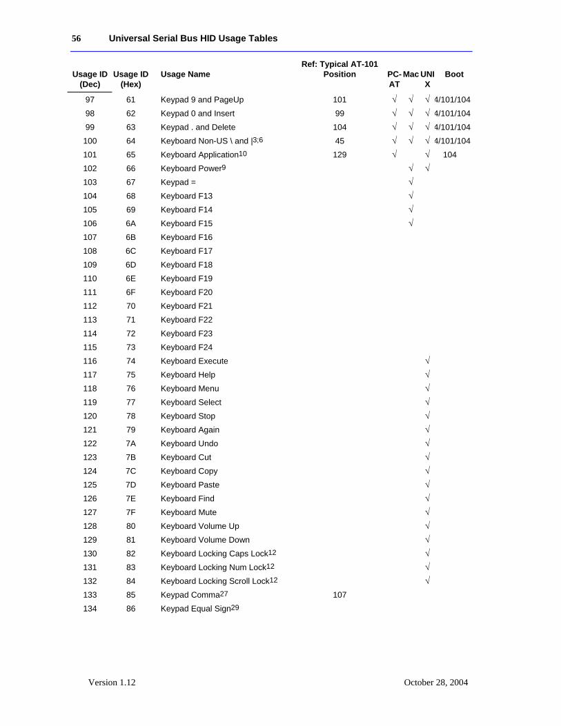
56 Universal Serial Bus HID Usage Tables
Version 1.12 October 28, 2004
Usage ID
(Dec)
Usage ID
(Hex)
Usage Name
Ref: Typical AT-101 Position
PC-AT
Mac
UNIX
Boot
97 61 Keypad 9 and PageUp 101 √ √ √ 4/101/104
98 62 Keypad 0 and Insert 99 √ √ √ 4/101/104
99 63 Keypad . and Delete 104 √ √ √ 4/101/104
100 64 Keyboard Non-US \ and |3;6 45 √ √ √ 4/101/104
101 65 Keyboard Application10 129 √ √ 104
102 66 Keyboard Power9 √ √
103 67 Keypad = √
104 68 Keyboard F13 √
105 69 Keyboard F14 √
106 6A Keyboard F15 √
107 6B Keyboard F16
108 6C Keyboard F17
109 6D Keyboard F18
110 6E Keyboard F19
111 6F Keyboard F20
112 70 Keyboard F21
113 71 Keyboard F22
114 72 Keyboard F23
115 73 Keyboard F24
116 74 Keyboard Execute √
117 75 Keyboard Help √
118 76 Keyboard Menu √
119 77 Keyboard Select √
120 78 Keyboard Stop √
121 79 Keyboard Again √
122 7A Keyboard Undo √
123 7B Keyboard Cut √
124 7C Keyboard Copy √
125 7D Keyboard Paste √
126 7E Keyboard Find √
127 7F Keyboard Mute √
128 80 Keyboard Volume Up √
129 81 Keyboard Volume Down √
130 82 Keyboard Locking Caps Lock12 √
131 83 Keyboard Locking Num Lock12 √
132 84 Keyboard Locking Scroll Lock12 √
133 85 Keypad Comma27 107
134 86 Keypad Equal Sign29
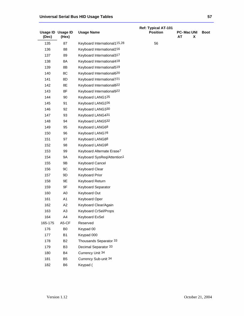
Universal Serial Bus HID Usage Tables 57
Version 1.12 October 21, 2004
Usage ID
(Dec)
Usage ID
(Hex)
Usage Name
Ref: Typical AT-101 Position
PC-AT
Mac
UNIX
Boot
135 87 Keyboard International115,28 56
136 88 Keyboard International216
137 89 Keyboard International317
138 8A Keyboard International418
139 8B Keyboard International519
140 8C Keyboard International620
141 8D Keyboard International721
142 8E Keyboard International822
143 8F Keyboard International922
144 90 Keyboard LANG125
145 91 Keyboard LANG226
146 92 Keyboard LANG330
147 93 Keyboard LANG431
148 94 Keyboard LANG532
149 95 Keyboard LANG68
150 96 Keyboard LANG78
151 97 Keyboard LANG88
152 98 Keyboard LANG98
153 99 Keyboard Alternate Erase7
154 9A Keyboard SysReq/Attention1
155 9B Keyboard Cancel
156 9C Keyboard Clear
157 9D Keyboard Prior
158 9E Keyboard Return
159 9F Keyboard Separator
160 A0 Keyboard Out
161 A1 Keyboard Oper
162 A2 Keyboard Clear/Again
163 A3 Keyboard CrSel/Props
164 A4 Keyboard ExSel
165-175 A5-CF Reserved
176 B0 Keypad 00
177 B1 Keypad 000
178 B2 Thousands Separator 33
179 B3 Decimal Separator 33
180 B4 Currency Unit 34
181 B5 Currency Sub-unit 34
182 B6 Keypad (
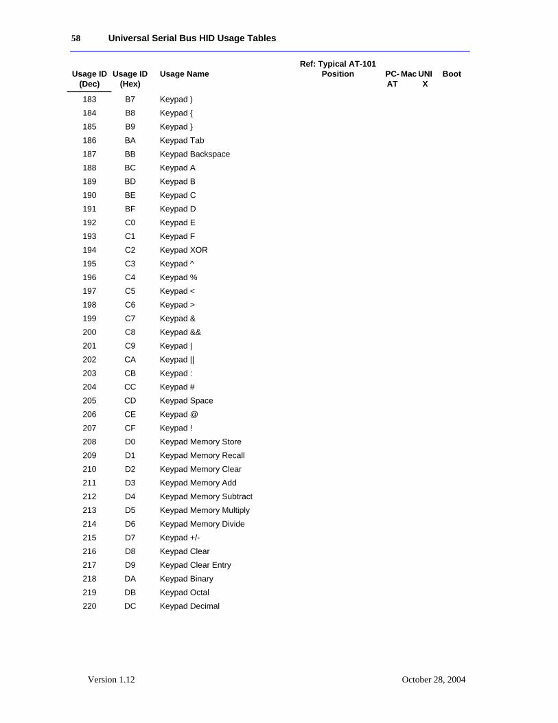
58 Universal Serial Bus HID Usage Tables
Version 1.12 October 28, 2004
Usage ID
(Dec)
Usage ID
(Hex)
Usage Name
Ref: Typical AT-101 Position
PC-AT
Mac
UNIX
Boot
183 B7 Keypad )
184 B8 Keypad {
185 B9 Keypad }
186 BA Keypad Tab
187 BB Keypad Backspace
188 BC Keypad A
189 BD Keypad B
190 BE Keypad C
191 BF Keypad D
192 C0 Keypad E
193 C1 Keypad F
194 C2 Keypad XOR
195 C3 Keypad ^
196 C4 Keypad %
197 C5 Keypad <
198 C6 Keypad >
199 C7 Keypad &
200 C8 Keypad &&
201 C9 Keypad |
202 CA Keypad ||
203 CB Keypad :
204 CC Keypad #
205 CD Keypad Space
206 CE Keypad @
207 CF Keypad !
208 D0 Keypad Memory Store
209 D1 Keypad Memory Recall
210 D2 Keypad Memory Clear
211 D3 Keypad Memory Add
212 D4 Keypad Memory Subtract
213 D5 Keypad Memory Multiply
214 D6 Keypad Memory Divide
215 D7 Keypad +/-
216 D8 Keypad Clear
217 D9 Keypad Clear Entry
218 DA Keypad Binary
219 DB Keypad Octal
220 DC Keypad Decimal
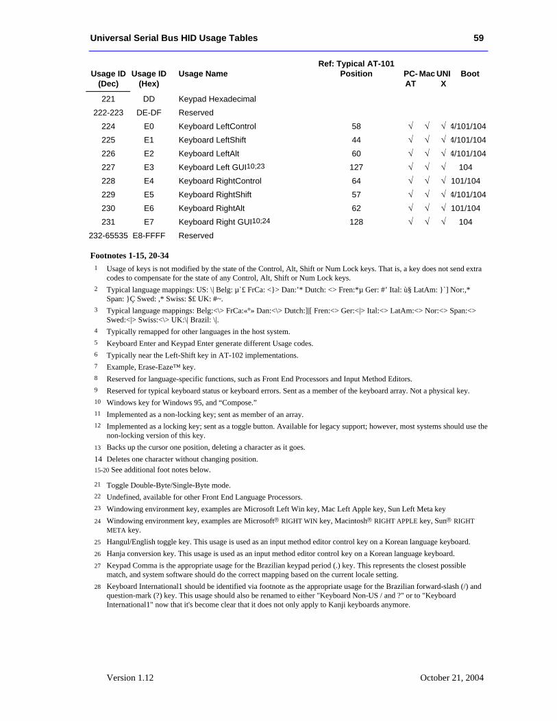
Universal Serial Bus HID Usage Tables 59
Version 1.12 October 21, 2004
Usage ID
(Dec)
Usage ID
(Hex)
Usage Name
Ref: Typical AT-101 Position
PC-AT
Mac
UNIX
Boot
221 DD Keypad Hexadecimal
222-223 DE-DF Reserved
224 E0 Keyboard LeftControl 58 √ √ √ 4/101/104
225 E1 Keyboard LeftShift 44 √ √ √ 4/101/104
226 E2 Keyboard LeftAlt 60 √ √ √ 4/101/104
227 E3 Keyboard Left GUI10;23 127 √ √ √ 104
228 E4 Keyboard RightControl 64 √ √ √ 101/104
229 E5 Keyboard RightShift 57 √ √ √ 4/101/104
230 E6 Keyboard RightAlt 62 √ √ √ 101/104
231 E7 Keyboard Right GUI10;24 128 √ √ √ 104
232-65535 E8-FFFF Reserved
Footnotes 1-15, 20-34
1 Usage of keys is not modified by the state of the Control, Alt, Shift or Num Lock keys. That is, a key does not send extra codes to compensate for the state of any Control, Alt, Shift or Num Lock keys.
2 Typical language mappings: US: \| Belg: µ`£ FrCa: <}> Dan:’* Dutch: <> Fren:*µ Ger: #’ Ital: ù§ LatAm: }`] Nor:,* Span: }Ç Swed: ,* Swiss: $£ UK: #~.
3 Typical language mappings: Belg:<\> FrCa:«°» Dan:<\> Dutch:]|[ Fren:<> Ger:<|> Ital:<> LatAm:<> Nor:<> Span:<> Swed:<|> Swiss:<\> UK:\| Brazil: \|.
4 Typically remapped for other languages in the host system. 5 Keyboard Enter and Keypad Enter generate different Usage codes. 6 Typically near the Left-Shift key in AT-102 implementations. 7 Example, Erase-Eaze™ key. 8 Reserved for language-specific functions, such as Front End Processors and Input Method Editors. 9 Reserved for typical keyboard status or keyboard errors. Sent as a member of the keyboard array. Not a physical key. 10 Windows key for Windows 95, and “Compose.” 11 Implemented as a non-locking key; sent as member of an array. 12 Implemented as a locking key; sent as a toggle button. Available for legacy support; however, most systems should use the
non-locking version of this key. 13 Backs up the cursor one position, deleting a character as it goes. 14 Deletes one character without changing position. 15-20 See additional foot notes below.
21 Toggle Double-Byte/Single-Byte mode. 22 Undefined, available for other Front End Language Processors. 23 Windowing environment key, examples are Microsoft Left Win key, Mac Left Apple key, Sun Left Meta key 24 Windowing environment key, examples are Microsoft® RIGHT WIN key, Macintosh® RIGHT APPLE key, Sun® RIGHT
META key. 25 Hangul/English toggle key. This usage is used as an input method editor control key on a Korean language keyboard. 26 Hanja conversion key. This usage is used as an input method editor control key on a Korean language keyboard. 27 Keypad Comma is the appropriate usage for the Brazilian keypad period (.) key. This represents the closest possible
match, and system software should do the correct mapping based on the current locale setting. 28 Keyboard International1 should be identified via footnote as the appropriate usage for the Brazilian forward-slash (/) and
question-mark (?) key. This usage should also be renamed to either "Keyboard Non-US / and ?" or to "Keyboard International1" now that it's become clear that it does not only apply to Kanji keyboards anymore.
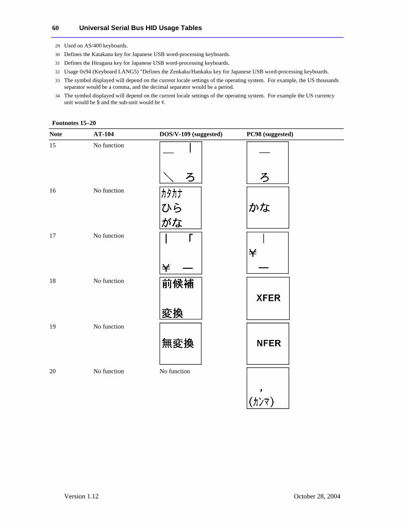
60 Universal Serial Bus HID Usage Tables
Version 1.12 October 28, 2004
29 Used on AS/400 keyboards. 30 Defines the Katakana key for Japanese USB word-processing keyboards. 31 Defines the Hiragana key for Japanese USB word-processing keyboards. 32 Usage 0x94 (Keyboard LANG5) "Defines the Zenkaku/Hankaku key for Japanese USB word-processing keyboards. 33 The symbol displayed will depend on the current locale settings of the operating system. For example, the US thousands
separator would be a comma, and the decimal separator would be a period. 34 The symbol displayed will depend on the current locale settings of the operating system. For example the US currency
unit would be $ and the sub-unit would be ¢.
Footnotes 15–20
Note AT-104 DOS/V-109 (suggested) PC98 (suggested)
15 No function
16 No function
17 No function
18 No function
19 No function
20 No function No function
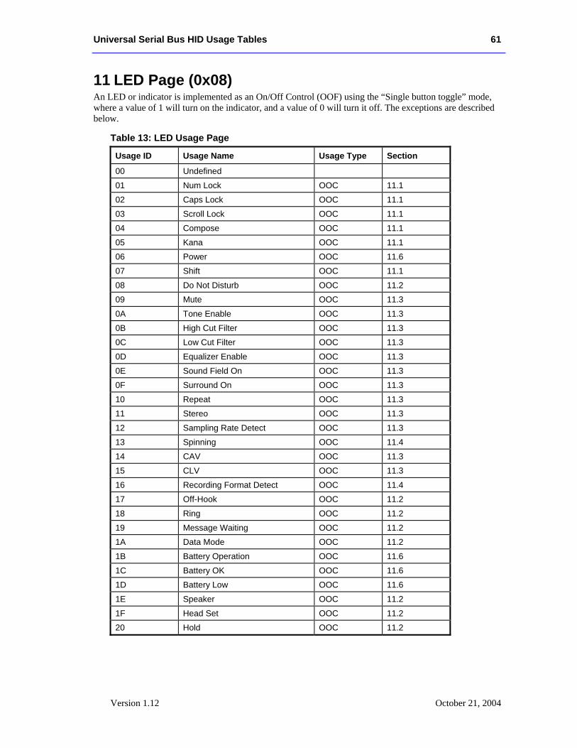
Universal Serial Bus HID Usage Tables 61
Version 1.12 October 21, 2004
11 LED Page (0x08) An LED or indicator is implemented as an On/Off Control (OOF) using the “Single button toggle” mode, where a value of 1 will turn on the indicator, and a value of 0 will turn it off. The exceptions are described below.
Table 13: LED Usage Page
Usage ID Usage Name Usage Type Section
00 Undefined
01 Num Lock OOC 11.1
02 Caps Lock OOC 11.1
03 Scroll Lock OOC 11.1
04 Compose OOC 11.1
05 Kana OOC 11.1
06 Power OOC 11.6
07 Shift OOC 11.1
08 Do Not Disturb OOC 11.2
09 Mute OOC 11.3
0A Tone Enable OOC 11.3
0B High Cut Filter OOC 11.3
0C Low Cut Filter OOC 11.3
0D Equalizer Enable OOC 11.3
0E Sound Field On OOC 11.3
0F Surround On OOC 11.3
10 Repeat OOC 11.3
11 Stereo OOC 11.3
12 Sampling Rate Detect OOC 11.3
13 Spinning OOC 11.4
14 CAV OOC 11.3
15 CLV OOC 11.3
16 Recording Format Detect OOC 11.4
17 Off-Hook OOC 11.2
18 Ring OOC 11.2
19 Message Waiting OOC 11.2
1A Data Mode OOC 11.2
1B Battery Operation OOC 11.6
1C Battery OK OOC 11.6
1D Battery Low OOC 11.6
1E Speaker OOC 11.2
1F Head Set OOC 11.2
20 Hold OOC 11.2
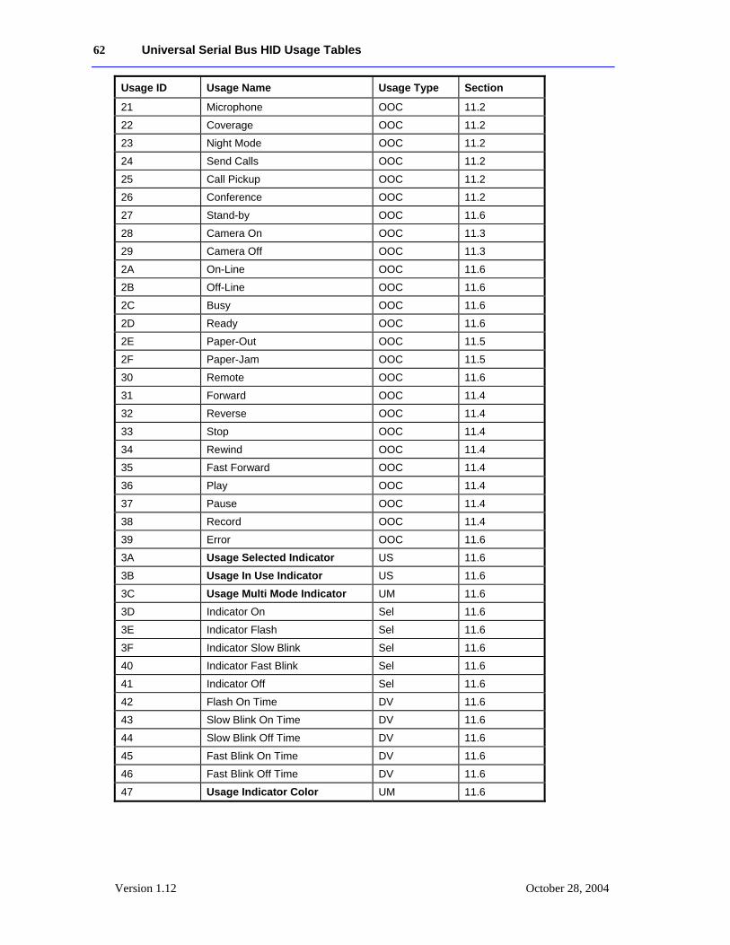
62 Universal Serial Bus HID Usage Tables
Version 1.12 October 28, 2004
Usage ID Usage Name Usage Type Section
21 Microphone OOC 11.2
22 Coverage OOC 11.2
23 Night Mode OOC 11.2
24 Send Calls OOC 11.2
25 Call Pickup OOC 11.2
26 Conference OOC 11.2
27 Stand-by OOC 11.6
28 Camera On OOC 11.3
29 Camera Off OOC 11.3
2A On-Line OOC 11.6
2B Off-Line OOC 11.6
2C Busy OOC 11.6
2D Ready OOC 11.6
2E Paper-Out OOC 11.5
2F Paper-Jam OOC 11.5
30 Remote OOC 11.6
31 Forward OOC 11.4
32 Reverse OOC 11.4
33 Stop OOC 11.4
34 Rewind OOC 11.4
35 Fast Forward OOC 11.4
36 Play OOC 11.4
37 Pause OOC 11.4
38 Record OOC 11.4
39 Error OOC 11.6
3A Usage Selected Indicator US 11.6
3B Usage In Use Indicator US 11.6
3C Usage Multi Mode Indicator UM 11.6
3D Indicator On Sel 11.6
3E Indicator Flash Sel 11.6
3F Indicator Slow Blink Sel 11.6
40 Indicator Fast Blink Sel 11.6
41 Indicator Off Sel 11.6
42 Flash On Time DV 11.6
43 Slow Blink On Time DV 11.6
44 Slow Blink Off Time DV 11.6
45 Fast Blink On Time DV 11.6
46 Fast Blink Off Time DV 11.6
47 Usage Indicator Color UM 11.6
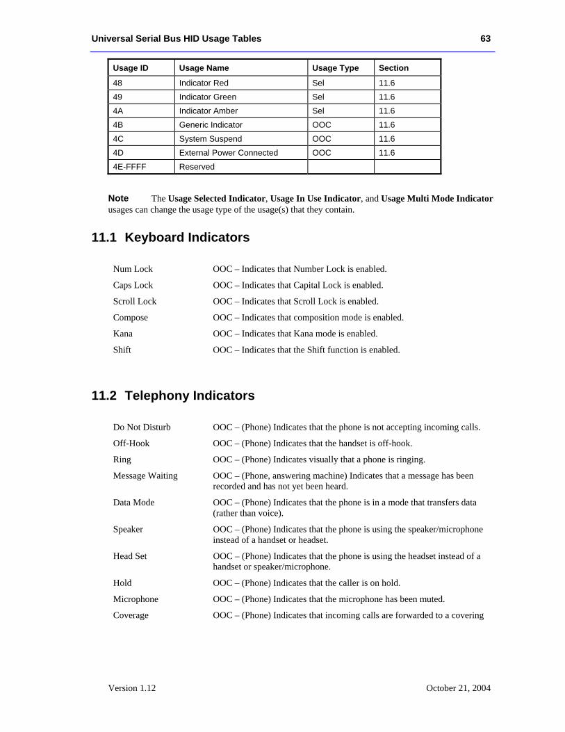
Universal Serial Bus HID Usage Tables 63
Version 1.12 October 21, 2004
Usage ID Usage Name Usage Type Section
48 Indicator Red Sel 11.6
49 Indicator Green Sel 11.6
4A Indicator Amber Sel 11.6
4B Generic Indicator OOC 11.6
4C System Suspend OOC 11.6
4D External Power Connected OOC 11.6
4E-FFFF Reserved
The Usage Selected Indicator, Usage In Use Indicator, and Usage Multi Mode Indicator usages can change the usage type of the usage(s) that they contain.
11.1 Keyboard Indicators
Num Lock OOC – Indicates that Number Lock is enabled.
Caps Lock OOC – Indicates that Capital Lock is enabled.
Scroll Lock OOC – Indicates that Scroll Lock is enabled.
Compose OOC – Indicates that composition mode is enabled.
Kana OOC – Indicates that Kana mode is enabled.
Shift OOC – Indicates that the Shift function is enabled.
11.2 Telephony Indicators
Do Not Disturb OOC – (Phone) Indicates that the phone is not accepting incoming calls.
Off-Hook OOC – (Phone) Indicates that the handset is off-hook.
Ring OOC – (Phone) Indicates visually that a phone is ringing.
Message Waiting OOC – (Phone, answering machine) Indicates that a message has been recorded and has not yet been heard.
Data Mode OOC – (Phone) Indicates that the phone is in a mode that transfers data (rather than voice).
Speaker OOC – (Phone) Indicates that the phone is using the speaker/microphone instead of a handset or headset.
Head Set OOC – (Phone) Indicates that the phone is using the headset instead of a handset or speaker/microphone.
Hold OOC – (Phone) Indicates that the caller is on hold.
Microphone OOC – (Phone) Indicates that the microphone has been muted.
Coverage OOC – (Phone) Indicates that incoming calls are forwarded to a covering
Note
64 Universal Serial Bus HID Usage Tables
Version 1.12 October 28, 2004
station.
Night Mode OOC – (Phone) Indicates that the phone is in after-hours mode.
Send Calls OOC – (Phone) Indicates that incoming calls are forwarded to another station.
Call Pickup OOC – (Phone) Indicates that a call in the user’s pickup group has been accepted. Pickup groups associate phones in an area. They allow a ringing phone to be picked up by any other phone in the group.
Conference OOC – (Phone) Indicates that the phone is in conference call mode.
11.3 Consumer Indicators
Mute OOC – Indicates that amplifier audio output is shut off.
Tone Enable OOC – Indicates that tone controls are functional.
High Cut Filter OOC – Indicates that the high cut filter is enabled.
Low Cut Filter OOC – Indicates that the low cut filter is enabled.
Equalizer Enable OOC – Indicates that tone shape processing is active.
Sound Field On OOC – Indicates that DSP processing is active.
Surround On OOC – Indicates that surround channel information is being decoded.
Repeat OOC – Indicates that the playback device is in repeat mode.
Stereo OOC – Indicates that the signal currently being received by the tuner is in stereo.
Sampling Rate Detect OOC – Indicates that a digital audio signal has been detected.
CAV OOC – Indicates that the video disc media is in Constant Angular Velocity format.
CLV OOC – Indicates that the video disc media is in Constant Linear Velocity format.
Camera On OOC – Indicates that the camera is recording images.
Camera Off OOC – Indicates that the camera is powered but not recording images.
11.4 Media Transport Indicators
Spinning OOC – Indicates that disc media is up to the speed required for playback/read.
Recording Format Detect
OOC – Indicates that a valid recording format has been detected.
Stop OOC – Indicates that a device’s media transport mechanism has been disengaged.
Universal Serial Bus HID Usage Tables 65
Version 1.12 October 21, 2004
Forward OOC – Indicates that a device’s media transport mechanism or a device is in forward mode.
Reverse OOC – Indicates that a device’s media transport mechanism or a device is in reverse mode.
Rewind OOC – Indicates that a device’s media transport mechanism is in rewind mode.
Fast Forward OOC – Indicates that a device’s media transport mechanism is in fast forward mode.
Play OOC – Indicates that a device’s media transport mechanism is in playback mode. This indicator may also be true when a device is recording.
Pause OOC – Indicates that a device’s media transport mechanism has been paused while playing back or recording.
Record OOC – Indicates that a device’s media transport mechanism is in record mode.
11.5 Printer Indicators
Paper-Out OOC – Indicates that the device is out of paper.
Paper-Jam OOC – Indicates that a paper jam has occurred in the device and operator intervention is required.
11.6 General Device Indicators
Power OOC – Indicates that the device is powered.
Stand-by OOC – Indicates that the device is in standby mode.
On-Line OOC – Indicates that the device is online.
Off-Line OOC – Indicates that the device is offline.
Busy OOC – Indicates that the device is busy executing operations.
Ready OOC – Indicates that the device is ready to execute operations.
Remote OOC – Indicates that the device is being controlled remotely.
Error OOC – Indicates that an error has occurred on the device.
Battery Operation OOC – Indicates that the device is currently battery powered.
Battery OK OOC – Indicates that the battery is in a nominal charge state.
Battery Low OOC – Indicates that the battery is in a low charge state.
Usage Selected Indicator
US – This collection allows the usages that it contains to be associated with a visual output (an LED) that indicates whether a control identified by the usage is selected. Usage Selected Indicator is a 1-bit field where 1 is
66 Universal Serial Bus HID Usage Tables
Version 1.12 October 28, 2004
selected and 0 is not selected. All usages found in this collection will be treated as On/Off Controls (OOC).
Usage In Use Indicator
US – This collection allows the usages that it contains to be associated with a visual output (an LED) that indicates whether a control identified by the usage is in use. Usage In Use Indicator is a 1-bit field where 1 is in use and 0 is not in use. All usages found in this collection will be treated as On/Off Controls (OOC).
Usage Multi Mode Indicator2
UM – This usage names a logical collection which must be contained in another collection. The usage attached to the encompassing collection is then identified as an indicator that supports multiple illumination modes. In this collection one or more of the following Indicator selectors will be found: On, Flash, Slow Blink, Fast Blink, and Off.
Indicator On Sel – Light indicator continuously.
Indicator Flash Sel – Single, momentary illumination of indicator.
Indicator Slow Blink Sel – Continuous flashing of the indicator at a slow rate.
Indicator Fast Blink Sel – Continuous flashing of the indicator at a fast rate.
Indicator Off Sel – Turn indicator illumination off.
Flash On Time DV – Duration that the indicator is illuminated in flash mode.
Slow Blink On Time DV – Duration that the indicator is illuminated in slow blink mode.
Slow Blink Off Time DV – Duration that the indicator is off in slow blink mode.
Fast Blink On Time DV – Duration that the indicator is illuminated in fast blink mode.
Fast Blink Off Time DV – Duration that the indicator is off in fast blink mode.
Usage Indicator Color2
UM – This collection allows the usage that contains it to be an indicator that supports multiple colors. All usages found in this collection will be treated as a Selectors (Sel) where one or more of the following Indicator selectors will be found: Indicator Off, Red, Green, and Amber.
Indicator Red Sel – Indicator color set to Red.
Indicator Green Sel – Indicator color set to Green.
Indicator Amber Sel – Indicator color set to Amber. This is typically implemented by asserting Red and Green simultaneously.
Generic Indicator OOC – This usage identifies an indicator that has no permanently assigned function.
System Suspend OOC – Indicates that the system is in a low power state, but is still powered and retaining some context.
External Power Connected
OOC – Indicates that a battery-operated system is connected to external power.
2 An indicator can support Multi Mode features and multiple colors simultaneously. To tie these functions together, they can be wrapped in a logical collection where the usage that is attached to the collection defines the purpose of the control.
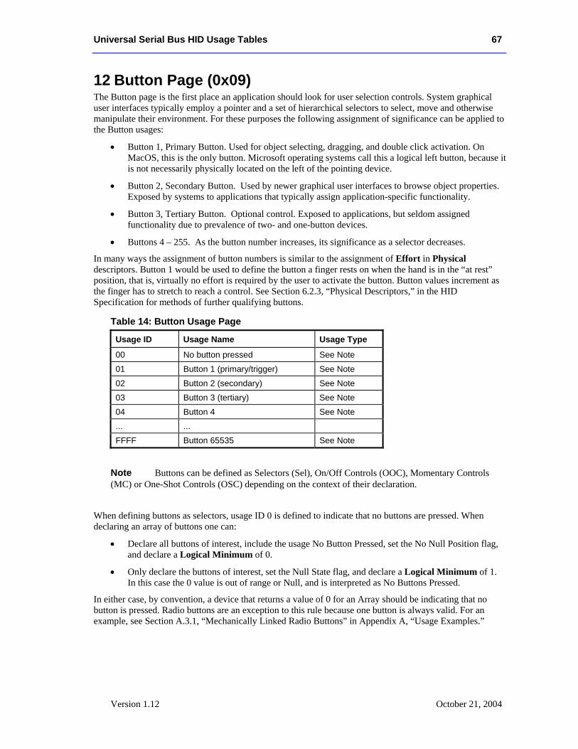
Universal Serial Bus HID Usage Tables 67
Version 1.12 October 21, 2004
12 Button Page (0x09) The Button page is the first place an application should look for user selection controls. System graphical user interfaces typically employ a pointer and a set of hierarchical selectors to select, move and otherwise manipulate their environment. For these purposes the following assignment of significance can be applied to the Button usages:
• Button 1, Primary Button. Used for object selecting, dragging, and double click activation. On MacOS, this is the only button. Microsoft operating systems call this a logical left button, because it is not necessarily physically located on the left of the pointing device.
• Button 2, Secondary Button. Used by newer graphical user interfaces to browse object properties. Exposed by systems to applications that typically assign application-specific functionality.
• Button 3, Tertiary Button. Optional control. Exposed to applications, but seldom assigned functionality due to prevalence of two- and one-button devices.
• Buttons 4 – 255. As the button number increases, its significance as a selector decreases.
In many ways the assignment of button numbers is similar to the assignment of Effort in Physical descriptors. Button 1 would be used to define the button a finger rests on when the hand is in the “at rest” position, that is, virtually no effort is required by the user to activate the button. Button values increment as the finger has to stretch to reach a control. See Section 6.2.3, “Physical Descriptors,” in the HID Specification for methods of further qualifying buttons.
Table 14: Button Usage Page
Usage ID Usage Name Usage Type
00 No button pressed See Note
01 Button 1 (primary/trigger) See Note
02 Button 2 (secondary) See Note
03 Button 3 (tertiary) See Note
04 Button 4 See Note
... ...
FFFF Button 65535 See Note
Buttons can be defined as Selectors (Sel), On/Off Controls (OOC), Momentary Controls (MC) or One-Shot Controls (OSC) depending on the context of their declaration.
When defining buttons as selectors, usage ID 0 is defined to indicate that no buttons are pressed. When declaring an array of buttons one can:
• Declare all buttons of interest, include the usage No Button Pressed, set the No Null Position flag, and declare a Logical Minimum of 0.
• Only declare the buttons of interest, set the Null State flag, and declare a Logical Minimum of 1. In this case the 0 value is out of range or Null, and is interpreted as No Buttons Pressed.
In either case, by convention, a device that returns a value of 0 for an Array should be indicating that no button is pressed. Radio buttons are an exception to this rule because one button is always valid. For an example, see Section A.3.1, “Mechanically Linked Radio Buttons” in Appendix A, “Usage Examples.”
Note
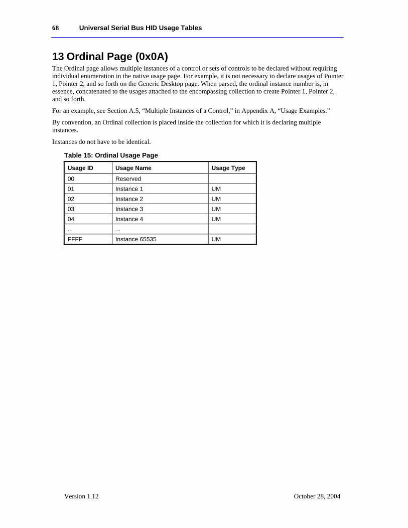
68 Universal Serial Bus HID Usage Tables
Version 1.12 October 28, 2004
13 Ordinal Page (0x0A) The Ordinal page allows multiple instances of a control or sets of controls to be declared without requiring individual enumeration in the native usage page. For example, it is not necessary to declare usages of Pointer 1, Pointer 2, and so forth on the Generic Desktop page. When parsed, the ordinal instance number is, in essence, concatenated to the usages attached to the encompassing collection to create Pointer 1, Pointer 2, and so forth.
For an example, see Section A.5, “Multiple Instances of a Control,” in Appendix A, “Usage Examples.”
By convention, an Ordinal collection is placed inside the collection for which it is declaring multiple instances.
Instances do not have to be identical.
Table 15: Ordinal Usage Page
Usage ID Usage Name Usage Type
00 Reserved
01 Instance 1 UM
02 Instance 2 UM
03 Instance 3 UM
04 Instance 4 UM
... ...
FFFF Instance 65535 UM
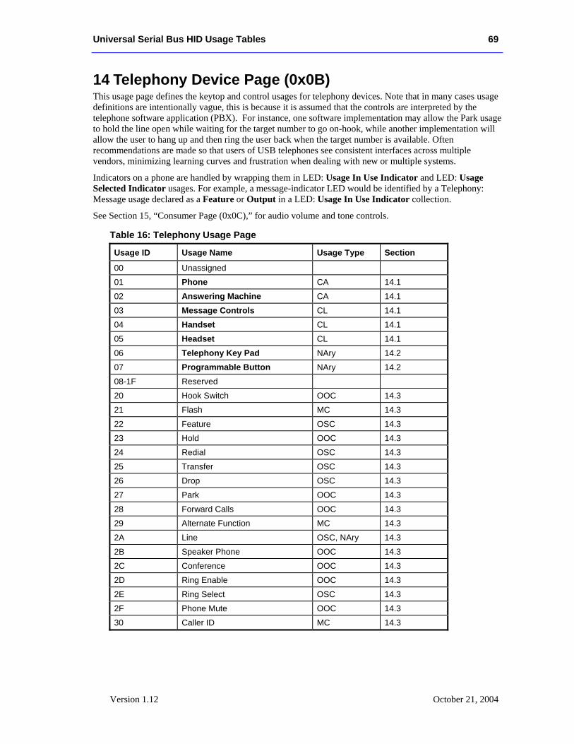
Universal Serial Bus HID Usage Tables 69
Version 1.12 October 21, 2004
14 Telephony Device Page (0x0B) This usage page defines the keytop and control usages for telephony devices. Note that in many cases usage definitions are intentionally vague, this is because it is assumed that the controls are interpreted by the telephone software application (PBX). For instance, one software implementation may allow the Park usage to hold the line open while waiting for the target number to go on-hook, while another implementation will allow the user to hang up and then ring the user back when the target number is available. Often recommendations are made so that users of USB telephones see consistent interfaces across multiple vendors, minimizing learning curves and frustration when dealing with new or multiple systems.
Indicators on a phone are handled by wrapping them in LED: Usage In Use Indicator and LED: Usage Selected Indicator usages. For example, a message-indicator LED would be identified by a Telephony: Message usage declared as a Feature or Output in a LED: Usage In Use Indicator collection.
See Section 15, “Consumer Page (0x0C),” for audio volume and tone controls.
Table 16: Telephony Usage Page
Usage ID Usage Name Usage Type Section
00 Unassigned
01 Phone CA 14.1
02 Answering Machine CA 14.1
03 Message Controls CL 14.1
04 Handset CL 14.1
05 Headset CL 14.1
06 Telephony Key Pad NAry 14.2
07 Programmable Button NAry 14.2
08-1F Reserved
20 Hook Switch OOC 14.3
21 Flash MC 14.3
22 Feature OSC 14.3
23 Hold OOC 14.3
24 Redial OSC 14.3
25 Transfer OSC 14.3
26 Drop OSC 14.3
27 Park OOC 14.3
28 Forward Calls OOC 14.3
29 Alternate Function MC 14.3
2A Line OSC, NAry 14.3
2B Speaker Phone OOC 14.3
2C Conference OOC 14.3
2D Ring Enable OOC 14.3
2E Ring Select OSC 14.3
2F Phone Mute OOC 14.3
30 Caller ID MC 14.3
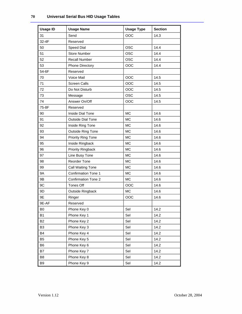
70 Universal Serial Bus HID Usage Tables
Version 1.12 October 28, 2004
Usage ID Usage Name Usage Type Section
31 Send OOC 14.3
32-4F Reserved
50 Speed Dial OSC 14.4
51 Store Number OSC 14.4
52 Recall Number OSC 14.4
53 Phone Directory OOC 14.4
54-6F Reserved
70 Voice Mail OOC 14.5
71 Screen Calls OOC 14.5
72 Do Not Disturb OOC 14.5
73 Message OSC 14.5
74 Answer On/Off OOC 14.5
75-8F Reserved
90 Inside Dial Tone MC 14.6
91 Outside Dial Tone MC 14.6
92 Inside Ring Tone MC 14.6
93 Outside Ring Tone MC 14.6
94 Priority Ring Tone MC 14.6
95 Inside Ringback MC 14.6
96 Priority Ringback MC 14.6
97 Line Busy Tone MC 14.6
98 Reorder Tone MC 14.6
99 Call Waiting Tone MC 14.6
9A Confirmation Tone 1 MC 14.6
9B Confirmation Tone 2 MC 14.6
9C Tones Off OOC 14.6
9D Outside Ringback MC 14.6
9E Ringer OOC 14.6
9E-AF Reserved
B0 Phone Key 0 Sel 14.2
B1 Phone Key 1 Sel 14.2
B2 Phone Key 2 Sel 14.2
B3 Phone Key 3 Sel 14.2
B4 Phone Key 4 Sel 14.2
B5 Phone Key 5 Sel 14.2
B6 Phone Key 6 Sel 14.2
B7 Phone Key 7 Sel 14.2
B8 Phone Key 8 Sel 14.2
B9 Phone Key 9 Sel 14.2
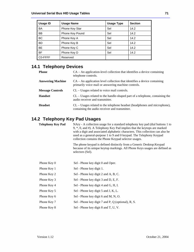
Universal Serial Bus HID Usage Tables 71
Version 1.12 October 21, 2004
Usage ID Usage Name Usage Type Section
BA Phone Key Star Sel 14.2
BB Phone Key Pound Sel 14.2
BC Phone Key A Sel 14.2
BD Phone Key B Sel 14.2
BE Phone Key C Sel 14.2
BF Phone Key D Sel 14.2
C0-FFFF Reserved
14.1 Telephony Devices Phone CA – An application-level collection that identifies a device containing
telephone controls.
Answering Machine CA – An application level collection that identifies a device containing primarily voice mail or answering machine controls.
Message Controls CL – Usages related to voice mail controls.
Handset CL – Usages related to the handle-shaped part of a telephone, containing the audio receiver and transmitter.
Headset CL – Usages related to the telephone headset (headphones and microphone), containing the audio receiver and transmitter.
14.2 Telephony Key Pad Usages Telephony Key Pad NAry - A collection usage for a standard telephony key pad (dial buttons 1 to
9, *, 0, and #). A Telephony Key Pad implies that the keytops are marked with a digit and associated alphabetic characters. This collection can also be used as a general-purpose 1 to 9 and 0 keypad. The Telephony Keypad collection contains the Phone Keypad selector usages.
The phone keypad is defined distinctly from a Generic Desktop:Keypad because of its unique keytop markings. All Phone Keys usages are defined as selectors (Sel).
Phone Key 0 Sel - Phone key digit 0 and Oper.
Phone Key 1 Sel - Phone key digit 1.
Phone Key 2 Sel - Phone key digit 2 and A, B, C.
Phone Key 3 Sel - Phone key digit 3 and D, E, F.
Phone Key 4 Sel - Phone key digit 4 and G, H, I.
Phone Key 5 Sel - Phone key digit 5 and J, K, L.
Phone Key 6 Sel - Phone key digit 6 and M, N, O.
Phone Key 7 Sel - Phone key digit 7 and P, Q (optional), R, S.
Phone Key 8 Sel - Phone key digit 8 and T, U, V.
72 Universal Serial Bus HID Usage Tables
Version 1.12 October 28, 2004
Phone Key 9 Sel - Phone key digit 9 and W, X, Y, Z (optional).
Phone Key Star Sel - Phone key Star (*).
Phone Key Pound Sel - Phone key Pound (#).
Phone Key A Sel - Phone key A
Phone Key B Sel - Phone key B
Phone Key C Sel - Phone key C
Phone Key D Sel - Phone key D
Programmable Button NAry - Programmable telephone buttons. This collection contains usages from the Button usage page. Programmable Buttons 1 through n are represented by Button page usages 1 through n, respectively.
14.3 Call Control Hook Switch OOC – Indicates that the handset is Off Hook. Hook Switch is a single bit
where 1 is Off Hook.
Flash MC – Generates a momentary On Hook condition to signal the application. Often used for alternate line selection.
Feature OSC – Selects operating feature.
Hold OOC – Places current call on hold.
Redial OSC – Redials last number dialed.
Transfer OSC – Transfers call to another extension.
Drop OSC – Disconnects the active call.
Park OOC – Waits for free line.
Forward Calls OOC – Forwards calls to another number.
Alternate Function MC – A modifier key, similar to a Shift key, that provides an alternate function to be selected on specific buttons. Pressing this button enables the alternate function mapping. Pressing an alternate function key terminates alternate-function mode.
Line OSC, NAry - Line selection. If the a the phone only supports a single line then the Line usage is defined as an OSC usage type. If the phone supports multiple lines then the Line usage can be defined as a NAry usage type, where the Line usage is applied to a Named Array collection. The Named Array collection contains Ordinal usage selectors, where Ordinal Instances represent the respective line numbers. If a phone can support multiple lines active at once then the Report Count associated with the array item can be greater than 1. See example in Appendix A.10.
Speaker Phone OOC – Enables speaker phone mode.
Conference OOC – Initiates conference call.
Ring Enable OOC – Enables ringer.
Universal Serial Bus HID Usage Tables 73
Version 1.12 October 21, 2004
Ring Select OSC – Selects ring tone. Typically, the caller presses Ring Select, then presses a dial digit to select the tone.
Phone Mute OOC – Disables audio to the called person. The caller can still hear the incoming audio.
Caller ID MC – Displays ID of caller.
Send MC - This indicates that the user has completed entering digits and is ready to begin routing the phone call. Note that this feature will NOT be used to alternate line selection as this is the functionality of the flash button. It should not be used to end the call either, as this is the function of the hook switch.
14.4 Speed Dial Controls Speed Dial OSC – Initiates speed dial operation.
Store Number OSC – Saves speed dial number.
Recall Number OSC – Recalls speed dial number on display.
Phone Directory OOC – Displays phone directory.
14.5 Voice Mail Controls Voice Mail OOC – Enters voice mail application.
Screen Calls OOC – Disables audio to called person and forwards calls to a voice mail application. The caller can still hear the incoming audio
Do Not Disturb OOC – Disables ring and speaker phone operation and forwards calls to a voice mail application.
Message OSC – Listens to voice message.
Answer On/Off OOC – Toggles answering machine operation.
14.6 Locally Generated Tones Some telephony devices generate tones locally vs. delivering transmitted tones over the audio input. These tones are played to the user via either the handset speaker or the speaker in a speakerphone telephone.
Inside Dial Tone MC - A tone that indicates to the user that the telephone is ready to place an inside call.
Outside Dial Tone MC - A tone that indicates to the user that the telephone is ready to place an outside call.
Inside Ring Tone MC – An in-house destination telephone is ringing.
Outside Ring Tone MC – An outside destination telephone is ringing.
Priority Ring Tone MC - The tone generated while a destination telephone is ringing as a result of a programmable function (like autodial, etc).
Inside Ringback MC – A ringback feature has been activated to an inside line.3
3 Ringback is a feature that a user could invoke when the destination is busy. Once the destination hangs up its current call, the destination’s phone “places a call” to the original user.
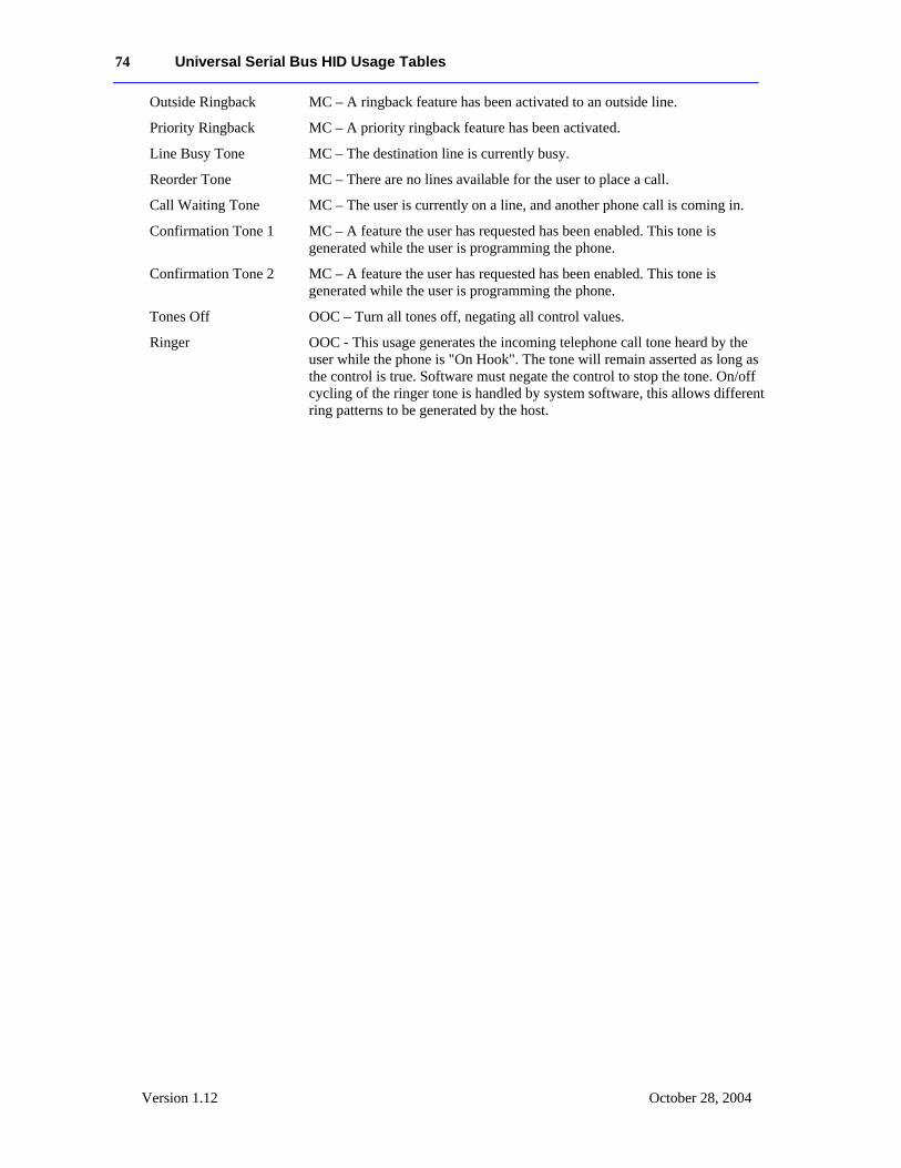
74 Universal Serial Bus HID Usage Tables
Version 1.12 October 28, 2004
Outside Ringback MC – A ringback feature has been activated to an outside line.
Priority Ringback MC – A priority ringback feature has been activated.
Line Busy Tone MC – The destination line is currently busy.
Reorder Tone MC – There are no lines available for the user to place a call.
Call Waiting Tone MC – The user is currently on a line, and another phone call is coming in.
Confirmation Tone 1 MC – A feature the user has requested has been enabled. This tone is generated while the user is programming the phone.
Confirmation Tone 2 MC – A feature the user has requested has been enabled. This tone is generated while the user is programming the phone.
Tones Off OOC – Turn all tones off, negating all control values.
Ringer OOC - This usage generates the incoming telephone call tone heard by the user while the phone is "On Hook". The tone will remain asserted as long as the control is true. Software must negate the control to stop the tone. On/off cycling of the ringer tone is handled by system software, this allows different ring patterns to be generated by the host.
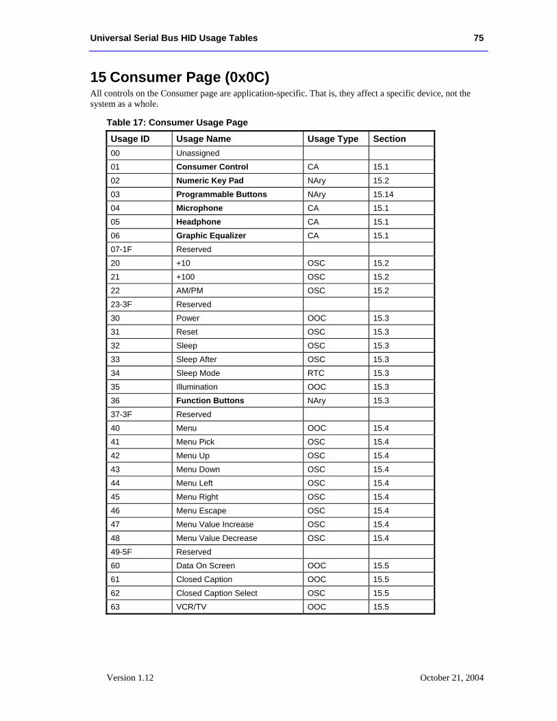
Universal Serial Bus HID Usage Tables 75
Version 1.12 October 21, 2004
15 Consumer Page (0x0C) All controls on the Consumer page are application-specific. That is, they affect a specific device, not the system as a whole.
Table 17: Consumer Usage Page
Usage ID Usage Name Usage Type Section 00 Unassigned
01 Consumer Control CA 15.1
02 Numeric Key Pad NAry 15.2
03 Programmable Buttons NAry 15.14
04 Microphone CA 15.1
05 Headphone CA 15.1
06 Graphic Equalizer CA 15.1
07-1F Reserved
20 +10 OSC 15.2
21 +100 OSC 15.2
22 AM/PM OSC 15.2
23-3F Reserved
30 Power OOC 15.3
31 Reset OSC 15.3
32 Sleep OSC 15.3
33 Sleep After OSC 15.3
34 Sleep Mode RTC 15.3
35 Illumination OOC 15.3
36 Function Buttons NAry 15.3
37-3F Reserved
40 Menu OOC 15.4
41 Menu Pick OSC 15.4
42 Menu Up OSC 15.4
43 Menu Down OSC 15.4
44 Menu Left OSC 15.4
45 Menu Right OSC 15.4
46 Menu Escape OSC 15.4
47 Menu Value Increase OSC 15.4
48 Menu Value Decrease OSC 15.4
49-5F Reserved
60 Data On Screen OOC 15.5
61 Closed Caption OOC 15.5
62 Closed Caption Select OSC 15.5
63 VCR/TV OOC 15.5
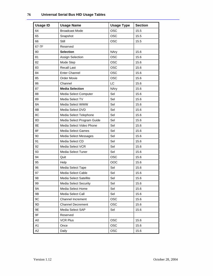
76 Universal Serial Bus HID Usage Tables
Version 1.12 October 28, 2004
Usage ID Usage Name Usage Type Section 64 Broadcast Mode OSC 15.5
65 Snapshot OSC 15.5
66 Still OSC 15.5
67-7F Reserved
80 Selection NAry 15.6
81 Assign Selection OSC 15.6
82 Mode Step OSC 15.6
83 Recall Last OSC 15.6
84 Enter Channel OSC 15.6
85 Order Movie OSC 15.6
86 Channel LC 15.6
87 Media Selection NAry 15.6
88 Media Select Computer Sel 15.6
89 Media Select TV Sel 15.6
8A Media Select WWW Sel 15.6
8B Media Select DVD Sel 15.6
8C Media Select Telephone Sel 15.6
8D Media Select Program Guide Sel 15.6
8E Media Select Video Phone Sel 15.6
8F Media Select Games Sel 15.6
90 Media Select Messages Sel 15.6
91 Media Select CD Sel 15.6
92 Media Select VCR Sel 15.6
93 Media Select Tuner Sel 15.6
94 Quit OSC 15.6
95 Help OOC 15.6
96 Media Select Tape Sel 15.6
97 Media Select Cable Sel 15.6
98 Media Select Satellite Sel 15.6
99 Media Select Security Sel 15.6
9A Media Select Home Sel 15.6
9B Media Select Call Sel 15.6
9C Channel Increment OSC 15.6
9D Channel Decrement OSC 15.6
9E Media Select SAP Sel 15.6
9F Reserved
A0 VCR Plus OSC 15.6
A1 Once OSC 15.6
A2 Daily OSC 15.6
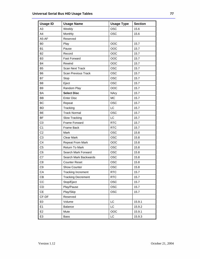
Universal Serial Bus HID Usage Tables 77
Version 1.12 October 21, 2004
Usage ID Usage Name Usage Type Section A3 Weekly OSC 15.6
A4 Monthly OSC 15.6
A5-AF Reserved
B0 Play OOC 15.7
B1 Pause OOC 15.7
B2 Record OOC 15.7
B3 Fast Forward OOC 15.7
B4 Rewind OOC 15.7
B5 Scan Next Track OSC 15.7
B6 Scan Previous Track OSC 15.7
B7 Stop OSC 15.7
B8 Eject OSC 15.7
B9 Random Play OOC 15.7
BA Select Disc NAry 15.7
BB Enter Disc MC 15.7
BC Repeat OSC 15.7
BD Tracking LC 15.7
BE Track Normal OSC 15.7
BF Slow Tracking LC 15.7
C0 Frame Forward RTC 15.7
C1 Frame Back RTC 15.7
C2 Mark OSC 15.8
C3 Clear Mark OSC 15.8
C4 Repeat From Mark OOC 15.8
C5 Return To Mark OSC 15.8
C6 Search Mark Forward OSC 15.8
C7 Search Mark Backwards OSC 15.8
C8 Counter Reset OSC 15.8
C9 Show Counter OSC 15.8
CA Tracking Increment RTC 15.7
CB Tracking Decrement RTC 15.7
CC Stop/Eject OSC 15.7
CD Play/Pause OSC 15.7
CE Play/Skip OSC 15.7
CF-DF Reserved
E0 Volume LC 15.9.1
E1 Balance LC 15.9.2
E2 Mute OOC 15.9.1
E3 Bass LC 15.9.3
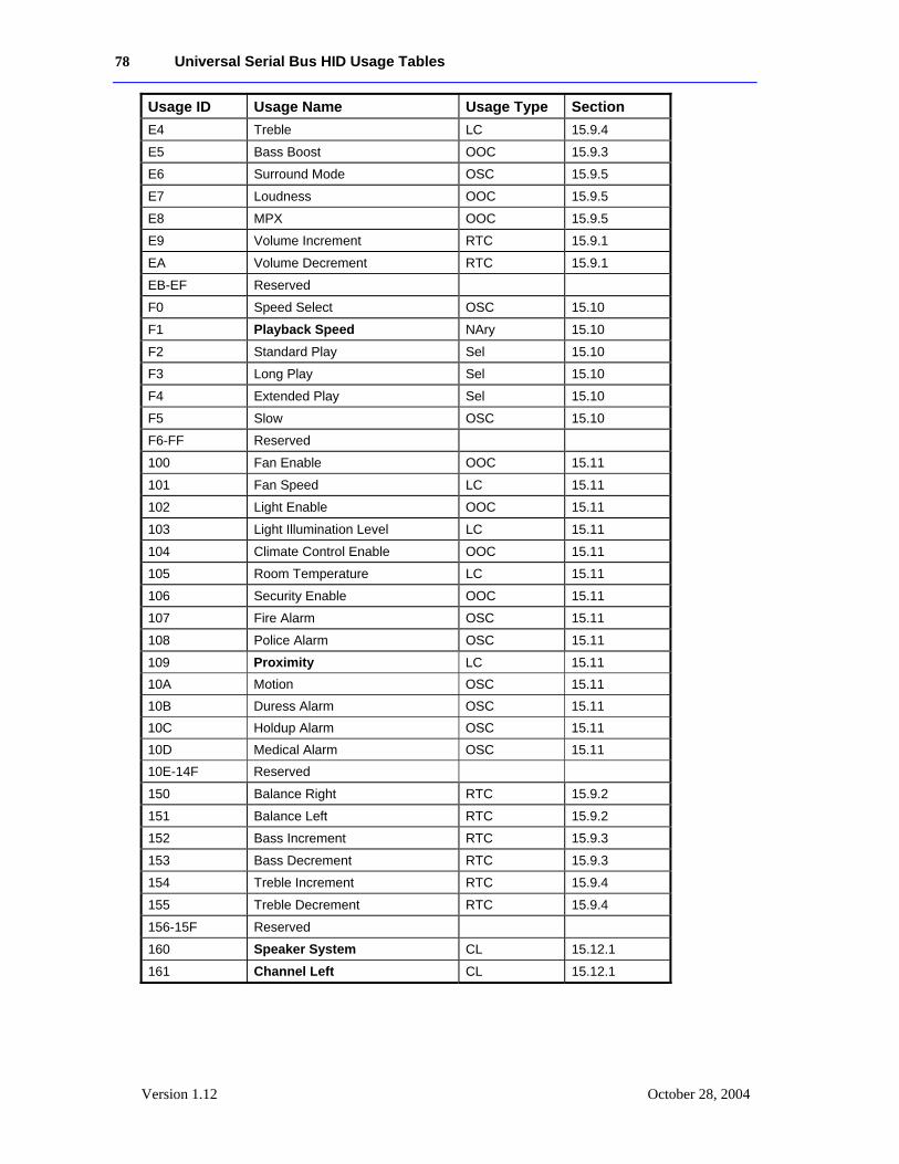
78 Universal Serial Bus HID Usage Tables
Version 1.12 October 28, 2004
Usage ID Usage Name Usage Type Section E4 Treble LC 15.9.4
E5 Bass Boost OOC 15.9.3
E6 Surround Mode OSC 15.9.5
E7 Loudness OOC 15.9.5
E8 MPX OOC 15.9.5
E9 Volume Increment RTC 15.9.1
EA Volume Decrement RTC 15.9.1
EB-EF Reserved
F0 Speed Select OSC 15.10
F1 Playback Speed NAry 15.10
F2 Standard Play Sel 15.10
F3 Long Play Sel 15.10
F4 Extended Play Sel 15.10
F5 Slow OSC 15.10
F6-FF Reserved
100 Fan Enable OOC 15.11
101 Fan Speed LC 15.11
102 Light Enable OOC 15.11
103 Light Illumination Level LC 15.11
104 Climate Control Enable OOC 15.11
105 Room Temperature LC 15.11
106 Security Enable OOC 15.11
107 Fire Alarm OSC 15.11
108 Police Alarm OSC 15.11
109 Proximity LC 15.11 10A Motion OSC 15.11 10B Duress Alarm OSC 15.11 10C Holdup Alarm OSC 15.11 10D Medical Alarm OSC 15.11 10E-14F Reserved
150 Balance Right RTC 15.9.2
151 Balance Left RTC 15.9.2
152 Bass Increment RTC 15.9.3
153 Bass Decrement RTC 15.9.3
154 Treble Increment RTC 15.9.4
155 Treble Decrement RTC 15.9.4
156-15F Reserved
160 Speaker System CL 15.12.1
161 Channel Left CL 15.12.1
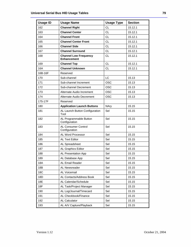
Universal Serial Bus HID Usage Tables 79
Version 1.12 October 21, 2004
Usage ID Usage Name Usage Type Section 162 Channel Right CL 15.12.1
163 Channel Center CL 15.12.1
164 Channel Front CL 15.12.1
165 Channel Center Front CL 15.12.1
166 Channel Side CL 15.12.1
167 Channel Surround CL 15.12.1
168 Channel Low Frequency Enhancement
CL 15.12.1
169 Channel Top CL 15.12.1
16A Channel Unknown CL 15.12.1
16B-16F Reserved
170 Sub-channel LC 15.13
171 Sub-channel Increment OSC 15.13
172 Sub-channel Decrement OSC 15.13
173 Alternate Audio Increment OSC 15.13
174 Alternate Audio Decrement OSC 15.13
175-17F Reserved
180 Application Launch Buttons NAry 15.15
181 AL Launch Button Configuration Tool
Sel 15.15
182 AL Programmable Button Configuration
Sel 15.15
183 AL Consumer Control Configuration
Sel 15.15
184 AL Word Processor Sel 15.15
185 AL Text Editor Sel 15.15
186 AL Spreadsheet Sel 15.15
187 AL Graphics Editor Sel 15.15
188 AL Presentation App Sel 15.15
189 AL Database App Sel 15.15
18A AL Email Reader Sel 15.15
18B AL Newsreader Sel 15.15
18C AL Voicemail Sel 15.15
18D AL Contacts/Address Book Sel 15.15
18E AL Calendar/Schedule Sel 15.15
18F AL Task/Project Manager Sel 15.15
190 AL Log/Journal/Timecard Sel 15.15
191 AL Checkbook/Finance Sel 15.15
192 AL Calculator Sel 15.15
193 AL A/V Capture/Playback Sel 15.15
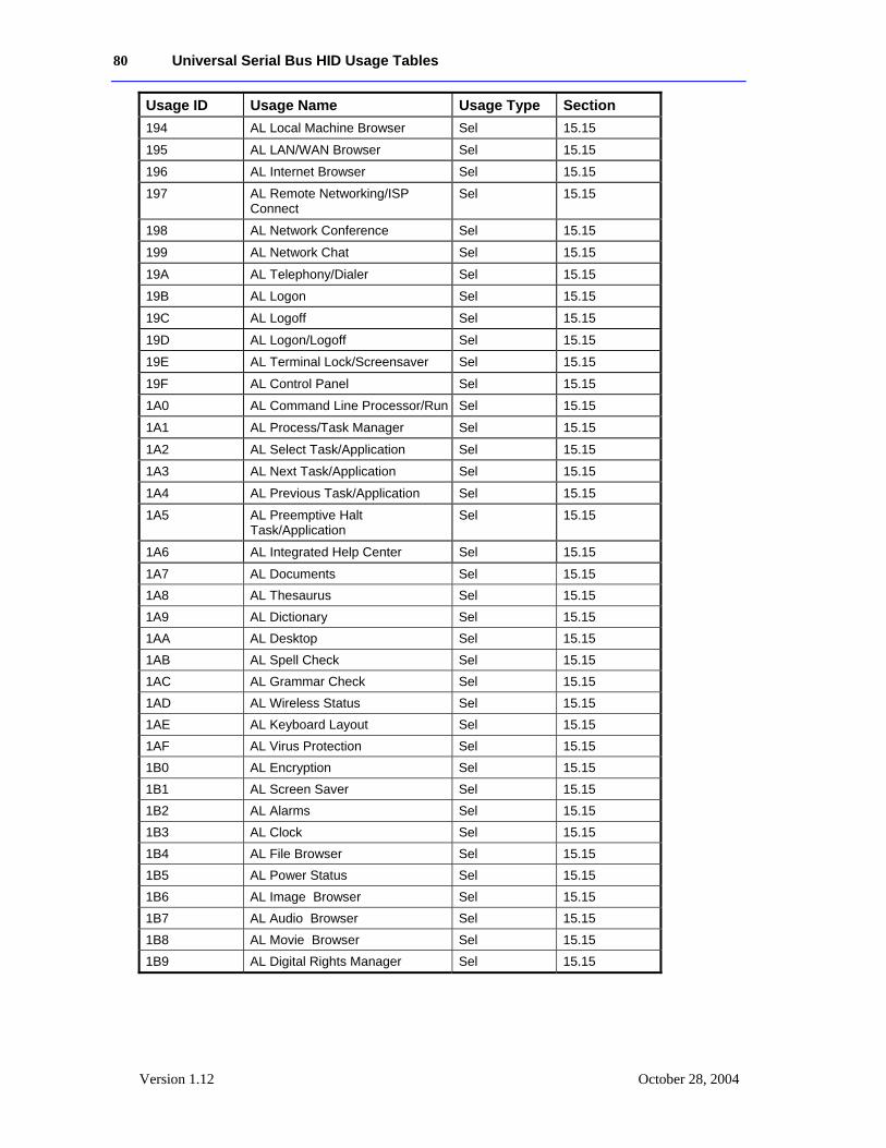
80 Universal Serial Bus HID Usage Tables
Version 1.12 October 28, 2004
Usage ID Usage Name Usage Type Section 194 AL Local Machine Browser Sel 15.15
195 AL LAN/WAN Browser Sel 15.15
196 AL Internet Browser Sel 15.15
197 AL Remote Networking/ISP Connect
Sel 15.15
198 AL Network Conference Sel 15.15
199 AL Network Chat Sel 15.15
19A AL Telephony/Dialer Sel 15.15
19B AL Logon Sel 15.15
19C AL Logoff Sel 15.15
19D AL Logon/Logoff Sel 15.15
19E AL Terminal Lock/Screensaver Sel 15.15
19F AL Control Panel Sel 15.15
1A0 AL Command Line Processor/Run Sel 15.15
1A1 AL Process/Task Manager Sel 15.15
1A2 AL Select Task/Application Sel 15.15
1A3 AL Next Task/Application Sel 15.15
1A4 AL Previous Task/Application Sel 15.15
1A5 AL Preemptive Halt Task/Application
Sel 15.15
1A6 AL Integrated Help Center Sel 15.15
1A7 AL Documents Sel 15.15 1A8 AL Thesaurus Sel 15.15 1A9 AL Dictionary Sel 15.15 1AA AL Desktop Sel 15.15 1AB AL Spell Check Sel 15.15 1AC AL Grammar Check Sel 15.15 1AD AL Wireless Status Sel 15.15 1AE AL Keyboard Layout Sel 15.15 1AF AL Virus Protection Sel 15.15 1B0 AL Encryption Sel 15.15 1B1 AL Screen Saver Sel 15.15 1B2 AL Alarms Sel 15.15 1B3 AL Clock Sel 15.15 1B4 AL File Browser Sel 15.15 1B5 AL Power Status Sel 15.15 1B6 AL Image Browser Sel 15.15 1B7 AL Audio Browser Sel 15.15 1B8 AL Movie Browser Sel 15.15 1B9 AL Digital Rights Manager Sel 15.15
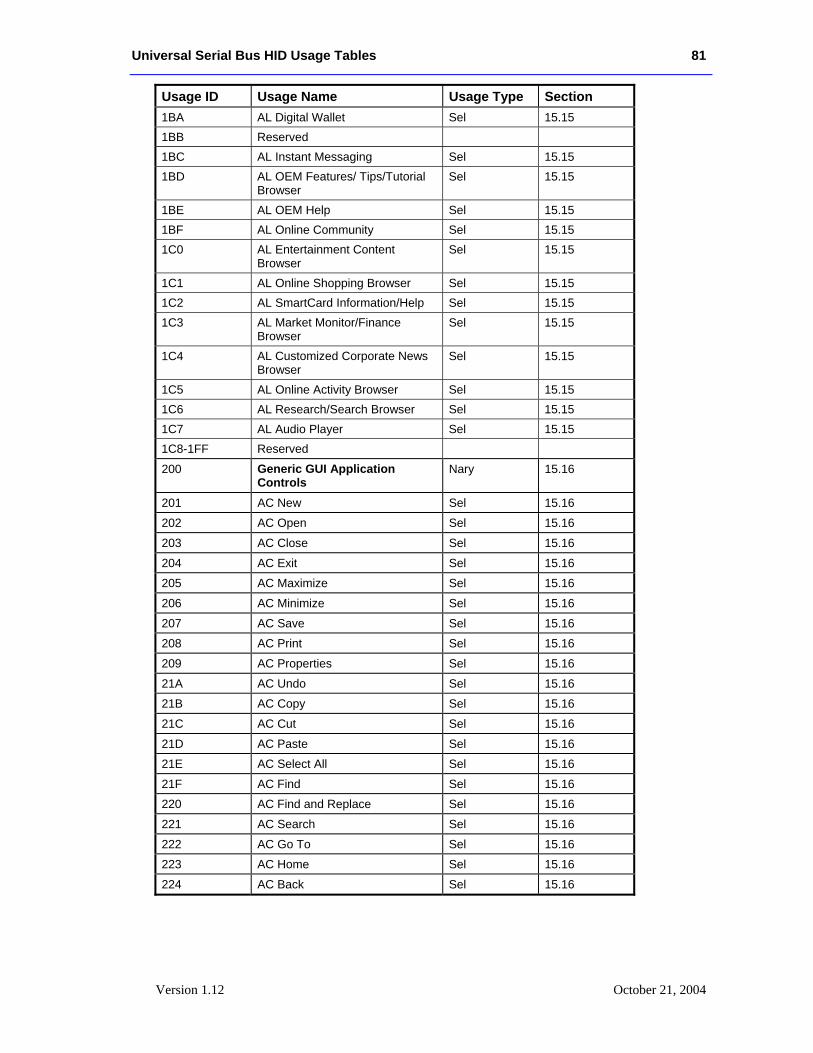
Universal Serial Bus HID Usage Tables 81
Version 1.12 October 21, 2004
Usage ID Usage Name Usage Type Section 1BA AL Digital Wallet Sel 15.15 1BB Reserved 1BC AL Instant Messaging Sel 15.15 1BD AL OEM Features/ Tips/Tutorial
Browser Sel 15.15
1BE AL OEM Help Sel 15.15 1BF AL Online Community Sel 15.15 1C0 AL Entertainment Content
Browser Sel 15.15
1C1 AL Online Shopping Browser Sel 15.15 1C2 AL SmartCard Information/Help Sel 15.15 1C3 AL Market Monitor/Finance
Browser Sel 15.15
1C4 AL Customized Corporate News Browser
Sel 15.15
1C5 AL Online Activity Browser Sel 15.15 1C6 AL Research/Search Browser Sel 15.15 1C7 AL Audio Player Sel 15.15 1C8-1FF Reserved
200 Generic GUI Application Controls
Nary 15.16
201 AC New Sel 15.16
202 AC Open Sel 15.16
203 AC Close Sel 15.16
204 AC Exit Sel 15.16
205 AC Maximize Sel 15.16
206 AC Minimize Sel 15.16
207 AC Save Sel 15.16
208 AC Print Sel 15.16
209 AC Properties Sel 15.16
21A AC Undo Sel 15.16
21B AC Copy Sel 15.16
21C AC Cut Sel 15.16
21D AC Paste Sel 15.16
21E AC Select All Sel 15.16
21F AC Find Sel 15.16
220 AC Find and Replace Sel 15.16
221 AC Search Sel 15.16
222 AC Go To Sel 15.16
223 AC Home Sel 15.16
224 AC Back Sel 15.16
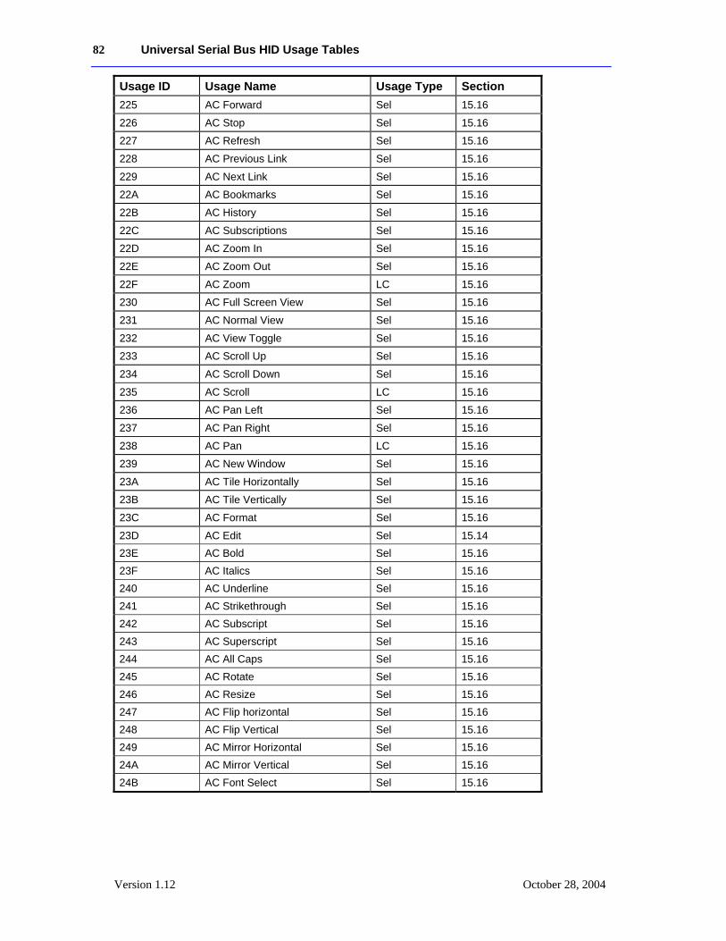
82 Universal Serial Bus HID Usage Tables
Version 1.12 October 28, 2004
Usage ID Usage Name Usage Type Section 225 AC Forward Sel 15.16
226 AC Stop Sel 15.16
227 AC Refresh Sel 15.16
228 AC Previous Link Sel 15.16
229 AC Next Link Sel 15.16
22A AC Bookmarks Sel 15.16
22B AC History Sel 15.16
22C AC Subscriptions Sel 15.16
22D AC Zoom In Sel 15.16
22E AC Zoom Out Sel 15.16
22F AC Zoom LC 15.16
230 AC Full Screen View Sel 15.16
231 AC Normal View Sel 15.16
232 AC View Toggle Sel 15.16
233 AC Scroll Up Sel 15.16
234 AC Scroll Down Sel 15.16
235 AC Scroll LC 15.16
236 AC Pan Left Sel 15.16
237 AC Pan Right Sel 15.16
238 AC Pan LC 15.16
239 AC New Window Sel 15.16
23A AC Tile Horizontally Sel 15.16
23B AC Tile Vertically Sel 15.16
23C AC Format Sel 15.16
23D AC Edit Sel 15.14 23E AC Bold Sel 15.16 23F AC Italics Sel 15.16 240 AC Underline Sel 15.16 241 AC Strikethrough Sel 15.16 242 AC Subscript Sel 15.16 243 AC Superscript Sel 15.16 244 AC All Caps Sel 15.16 245 AC Rotate Sel 15.16 246 AC Resize Sel 15.16 247 AC Flip horizontal Sel 15.16 248 AC Flip Vertical Sel 15.16 249 AC Mirror Horizontal Sel 15.16 24A AC Mirror Vertical Sel 15.16 24B AC Font Select Sel 15.16
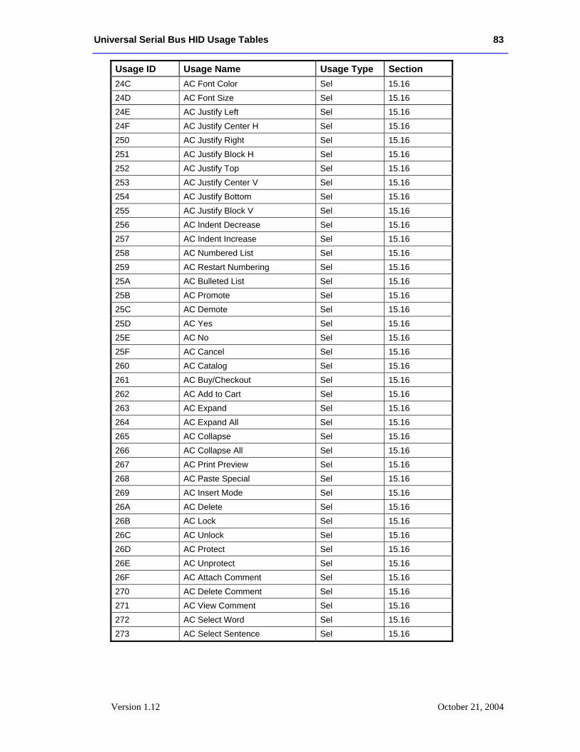
Universal Serial Bus HID Usage Tables 83
Version 1.12 October 21, 2004
Usage ID Usage Name Usage Type Section 24C AC Font Color Sel 15.16 24D AC Font Size Sel 15.16 24E AC Justify Left Sel 15.16 24F AC Justify Center H Sel 15.16 250 AC Justify Right Sel 15.16 251 AC Justify Block H Sel 15.16 252 AC Justify Top Sel 15.16 253 AC Justify Center V Sel 15.16 254 AC Justify Bottom Sel 15.16 255 AC Justify Block V Sel 15.16 256 AC Indent Decrease Sel 15.16 257 AC Indent Increase Sel 15.16 258 AC Numbered List Sel 15.16 259 AC Restart Numbering Sel 15.16 25A AC Bulleted List Sel 15.16 25B AC Promote Sel 15.16 25C AC Demote Sel 15.16 25D AC Yes Sel 15.16 25E AC No Sel 15.16 25F AC Cancel Sel 15.16 260 AC Catalog Sel 15.16 261 AC Buy/Checkout Sel 15.16 262 AC Add to Cart Sel 15.16 263 AC Expand Sel 15.16 264 AC Expand All Sel 15.16 265 AC Collapse Sel 15.16 266 AC Collapse All Sel 15.16 267 AC Print Preview Sel 15.16 268 AC Paste Special Sel 15.16 269 AC Insert Mode Sel 15.16 26A AC Delete Sel 15.16 26B AC Lock Sel 15.16 26C AC Unlock Sel 15.16 26D AC Protect Sel 15.16 26E AC Unprotect Sel 15.16 26F AC Attach Comment Sel 15.16 270 AC Delete Comment Sel 15.16 271 AC View Comment Sel 15.16 272 AC Select Word Sel 15.16 273 AC Select Sentence Sel 15.16
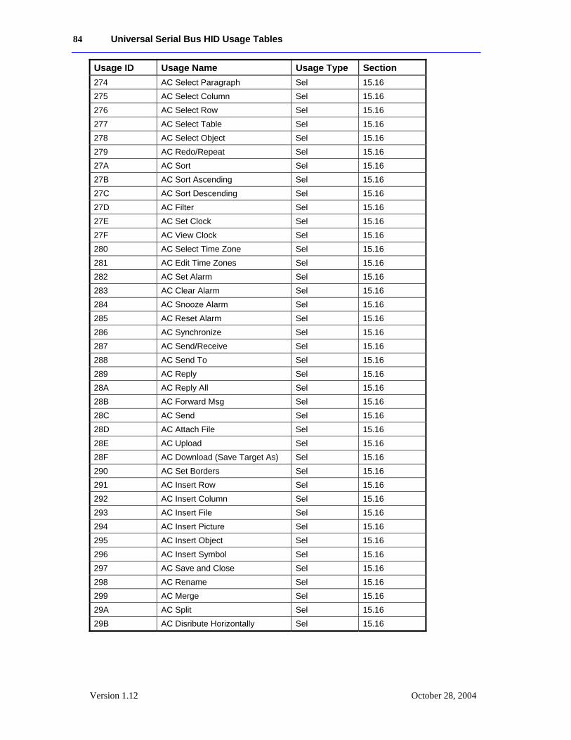
84 Universal Serial Bus HID Usage Tables
Version 1.12 October 28, 2004
Usage ID Usage Name Usage Type Section 274 AC Select Paragraph Sel 15.16 275 AC Select Column Sel 15.16 276 AC Select Row Sel 15.16 277 AC Select Table Sel 15.16 278 AC Select Object Sel 15.16 279 AC Redo/Repeat Sel 15.16 27A AC Sort Sel 15.16 27B AC Sort Ascending Sel 15.16 27C AC Sort Descending Sel 15.16 27D AC Filter Sel 15.16 27E AC Set Clock Sel 15.16 27F AC View Clock Sel 15.16 280 AC Select Time Zone Sel 15.16 281 AC Edit Time Zones Sel 15.16 282 AC Set Alarm Sel 15.16 283 AC Clear Alarm Sel 15.16 284 AC Snooze Alarm Sel 15.16 285 AC Reset Alarm Sel 15.16 286 AC Synchronize Sel 15.16 287 AC Send/Receive Sel 15.16 288 AC Send To Sel 15.16 289 AC Reply Sel 15.16 28A AC Reply All Sel 15.16 28B AC Forward Msg Sel 15.16 28C AC Send Sel 15.16 28D AC Attach File Sel 15.16 28E AC Upload Sel 15.16 28F AC Download (Save Target As) Sel 15.16 290 AC Set Borders Sel 15.16 291 AC Insert Row Sel 15.16 292 AC Insert Column Sel 15.16 293 AC Insert File Sel 15.16 294 AC Insert Picture Sel 15.16 295 AC Insert Object Sel 15.16 296 AC Insert Symbol Sel 15.16 297 AC Save and Close Sel 15.16 298 AC Rename Sel 15.16 299 AC Merge Sel 15.16 29A AC Split Sel 15.16 29B AC Disribute Horizontally Sel 15.16
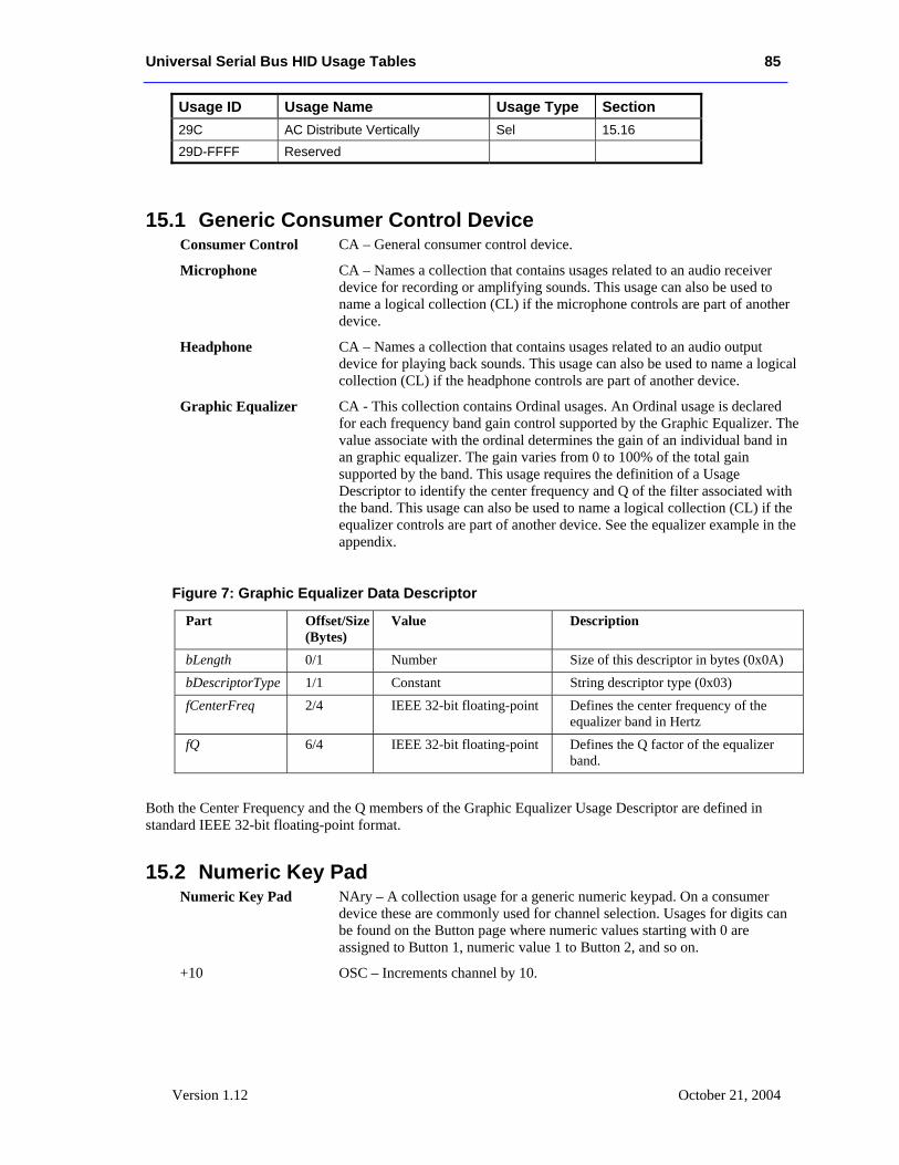
Universal Serial Bus HID Usage Tables 85
Version 1.12 October 21, 2004
Usage ID Usage Name Usage Type Section 29C AC Distribute Vertically Sel 15.16 29D-FFFF Reserved
15.1 Generic Consumer Control Device Consumer Control CA – General consumer control device.
Microphone CA – Names a collection that contains usages related to an audio receiver device for recording or amplifying sounds. This usage can also be used to name a logical collection (CL) if the microphone controls are part of another device.
Headphone CA – Names a collection that contains usages related to an audio output device for playing back sounds. This usage can also be used to name a logical collection (CL) if the headphone controls are part of another device.
Graphic Equalizer CA - This collection contains Ordinal usages. An Ordinal usage is declared for each frequency band gain control supported by the Graphic Equalizer. The value associate with the ordinal determines the gain of an individual band in an graphic equalizer. The gain varies from 0 to 100% of the total gain supported by the band. This usage requires the definition of a Usage Descriptor to identify the center frequency and Q of the filter associated with the band. This usage can also be used to name a logical collection (CL) if the equalizer controls are part of another device. See the equalizer example in the appendix.
Figure 7: Graphic Equalizer Data Descriptor
Part Offset/Size (Bytes)
Value Description
bLength 0/1 Number Size of this descriptor in bytes (0x0A) bDescriptorType 1/1 Constant String descriptor type (0x03) fCenterFreq 2/4 IEEE 32-bit floating-point Defines the center frequency of the
equalizer band in Hertz fQ 6/4 IEEE 32-bit floating-point Defines the Q factor of the equalizer
band.
Both the Center Frequency and the Q members of the Graphic Equalizer Usage Descriptor are defined in standard IEEE 32-bit floating-point format.
15.2 Numeric Key Pad Numeric Key Pad NAry – A collection usage for a generic numeric keypad. On a consumer
device these are commonly used for channel selection. Usages for digits can be found on the Button page where numeric values starting with 0 are assigned to Button 1, numeric value 1 to Button 2, and so on.
+10 OSC – Increments channel by 10.
86 Universal Serial Bus HID Usage Tables
Version 1.12 October 28, 2004
+100 OSC – Increments channel by 100.
AM/PM OSC – Toggles between AM and PM for time entry.
15.3 General Controls Power OOC – Controls the application-specific power state. For global power control,
see System Controls on the Generic Desktop Usage page.
Reset OSC – Resets the device. All volatile settings revert to the defaults.
Sleep OSC – Initiates low power state on application-specific device now.
Sleep After OSC – Sets inactivity timeout to a value. The Sleep After button will be followed with the timeout value in minutes entered on a numeric keypad.
Sleep Mode RTC – Cycle through available sleep delays, such as no sleeping, 5 minutes, 10 minutes, 30 minutes, etc. The last selected mode will be enabled.
Illumination OOC – Toggles illumination of consumer control's buttons and controls on/off.
Function Buttons NAry – A collection usage for generic function buttons. On a consumer device, these are commonly used for user-assigned functions. Usages for function buttons can be found on the Button page where Function Button 1 is assigned to Button 1, Function Button 2 to Button 2, and so on.
15.4 Menu Controls Menu OOC – Initiates on-device-display main menu. Sets a mode in which the other
menu controls are active. In this mode, a subsequent menu press will cancel the mode.
Menu Pick OSC – Picks an item from an on-screen menu.
Menu Up OSC – Moves the selection up in a device-displayed menu.
Menu Down OSC – Moves the selection down in a device-displayed menu.
Menu Left OSC – Moves the selection left in a device-displayed menu.
Menu Right OSC – Moves the selection right in a device-displayed menu.
Menu Escape OSC – Backs up a level in the on-screen menu system.
Menu Value Increase OSC – Increments the value of the currently selected menu item. For example, after using a menu to select a volume control, the user can modify the volume level using this control.
Menu Value Decrease OSC – Decrements the value of the currently selected menu item.
15.5 Display Controls Data On Screen OOC – Superimposes state data on the monitor video. Typically, channel
information is displayed.
Closed Caption OOC – Enables closed-caption display.
Closed Caption Select OSC – Cycles through closed-caption viewing options.
VCR/TV OOC – Selects a recording source for VCR.
Universal Serial Bus HID Usage Tables 87
Version 1.12 October 21, 2004
Broadcast Mode OSC – Cycles between available broadcast modes, such as Broadcast, CATV, etc. The last selected mode is enabled.
Snapshot OSC – Captures the screen or image of the currently selected window.
Still OSC – Pauses playback in the currently selected window.
15.6 Selection Controls Selection NAry – A collection usage for a number of discrete selections. On a
consumer device, these are commonly used for “favorite” selections. Usages for the selections can be found on the Button page where the choices are assigned to Button 1 and so on.
Assign Selection OSC – This button works in conjunction with the Selection usage. To assign the current channel or mode to a selection button, the user presses the Assign Selection button followed by a button in the Selection named array.
Mode Step OSC – Steps through devices (TV, VCR, cable) in a multi-mode remote.
Recall Last OSC – Returns to the last selected channel or mode.
Enter Channel OSC – Interprets the previous number entry as channel information.
Order Movie OSC – Requests pay-per-view entertainment.
Channel LC – Channel selection control where the range of possible values is equal to the number of channels supported by the device.
Channel Increment OSC – Channel control where each activation of the control increments the current channel selection to the next available channel.
Channel Decrement OSC – Channel control where each activation of the control decrements the current channel selection to the next available channel.
VCR Plus OSC – Initiates (and optionally terminates) VCR Plus code entry mode.
The controls Once, Daily, Weekly, and Monthly are typically used for programming record operations.
Once OSC – Performs the operation once.
Daily OSC – Performs the operation once a day.
Weekly OSC – Performs the operation once a week.
Monthly OSC – Performs the operation once a month.
Media Selection NAry – Identifies the media source to be manipulated or displayed. This collection will contain one of the following Media Select usages.
Media Select Computer Sel – Selects the computer display.
Media Select TV Sel – Selects the television display.
Media Select WWW Sel – Selects World Wide Web access.
Media Select DVD Sel – Selects the DVD drive.
Media Select Telephone Sel – Selects telephone mode.
88 Universal Serial Bus HID Usage Tables
Version 1.12 October 28, 2004
Media Select Program Guide
Sel – Selects the viewing guide.
Media Select Video Phone
Sel – Selects videophone mode.
Media Select Games Sel – Selects gaming mode.
Media Select Messages Sel – Selects message mode.
Media Select CD Sel – Selects the CD drive.
Media Select VCR Sel – Selects the VCR.
Media Select Tuner Sel – Selects the tuner.
Media Select Tape Sel – Select the audio tape.
Media Select Cable Sel – Selects the cable receiver.
Media Select Satellite Sel – Selects the satellite receiver.
Media Select Security Sel – Selects the security status display.
Media Select Home Sel – Selects the home system status display.
Media Select Call Sel – Selects the telephone call status display.
Quit OSC – Exits the current mode.
Help OOC – Displays the help screen.
15.7 Transport Controls Play OOC – Begins streaming linear media.
Pause OOC – Stops streaming linear media.
Record OOC – Initiates transferring input data to media.
Fast Forward OOC – Initiates fast forward scan of linear media.
Rewind OOC – Initiates fast reverse scan of linear media.
Scan Next Track OSC – Moves to the next chapter or track boundary.
Scan Previous Track OSC – Moves to the previous chapter or track boundary.
Stop OSC – Halts scanning, streaming, or recording linear media.
Eject OSC – Removes media from the player.
Stop/Eject OSC – If linear media is scanning, streaming, or recording, stops the media stream. If linear media is halted, removes the media from the player.
Play/Pause OSC – If linear media is scanning, streaming, or recording, momentarily stops the media stream. If linear media is paused, resumes streaming.
Play/Skip OSC – If linear media is halted, begins streaming. If linear media is already streaming, advances to the next channel.
Random Play OOC – Random selection of tracks.
Repeat OSC – Repeat selection of tracks.
Select Disc NAry – Attached to a collection that defines the selection of one of many
Universal Serial Bus HID Usage Tables 89
Version 1.12 October 21, 2004
disks. The allowed disk numbers are enumerated with the declaration of ordinals in the Select Disc named array.
Enter Disc MC – This button works in conjunction with the Numeric Key Pad usage. To select a disk, the user presses the Enter Disc button followed by the entry of the desired disc number on the numeric key pad.
Tracking LC – Adjusts media tracking.
Tracking Increment RTC – Asserting this control increments the current value of media tracking until the maximum value is reached. Typically implemented as a single button.
Tracking Decrement RTC – Asserting this control decrements the current value of media tracking until the minimum value is reached. Typically implemented as a single button.
Track Normal OSC – Sets media tracking to default or automatic value.
Slow Tracking LC – Adjusts media slow tracking.
Frame Forward RTC – Moves forward one video frame.
Frame Back RTC – Moves back one video frame.
15.8 Search Controls Search controls either place a physical flag, index or mark on the magnetic media, or use the position or frame counter to flag points of interest. The search controls allow identifying and moving between these points of interest.
Mark OSC – Marks a reference point on the media. Synonymous with the “counter memory” function found on some transport devices.
Clear Mark OSC – Removes a marked reference point from the media.
Repeat From Mark OOC – Marks the current position as the end of the block and repeat-plays the block starting from the marked beginning of the block.
Return To Mark OSC – Positions at the last detected mark and plays.
Search Mark Forward OSC – Searches forward for a mark.
Search Mark Backwards
OSC – Searches backward for a mark.
Counter Reset OSC – Resets the time, position, or frame counter.
Show Counter OSC – Toggles between the position counter and the time display.
15.9 Audio Controls
15.9.1 Volume An application should check the Volume, Volume Increment and Volume Decrement usages when determining whether a device supports volume controls.
Volume LC – Audio volume control.
Volume Increment RTC – Asserting this control increments the current value of audio volume until the maximum value is reached. It is typically implemented as a single
90 Universal Serial Bus HID Usage Tables
Version 1.12 October 28, 2004
button.
Volume Decrement RTC – Asserting this control decrements the current value of audio volume until the minimum value is reached. It is typically implemented as a single button.
Mute OOC – Audio mute control. Sets the audio output level to the minimum value without affecting the current volume level. When Mute is disabled, the previous audio level will be restored.
15.9.2 Balance An application should check the Balance, Balance Right and Balance Left usages when determining whether a device supports balance controls.
Balance LC – Audio balance control.
Balance Right RTC – Asserting this control adjusts the audio output towards the right channel until the maximum value is reached. It is typically implemented as a single button.
Balance Left RTC – Asserting this control adjusts the audio to the left channel until the maximum value is reached. It is typically implemented as a single button.
15.9.3 Bass An application should check the Bass, Bass Increment and Bass Decrement usages when determining whether a device supports bass controls.
Bass LC – Audio bass control.
Bass Increment RTC – Asserting this control increments the current value of the audio bass control until the maximum value is reached. It is typically implemented as a single button.
Bass Decrement RTC – Asserting this control decrements the current value of the audio bass control until the minimum value is reached. It is typically implemented as a single button.
Bass Boost OOC – Enables audio bass boost.
15.9.4 Treble An application should check the Treble, Treble Increment and Treble Decrement usages when determining whether a device supports treble controls.
Treble LC – Audio treble control.
Treble Increment RTC – Asserting this control increments the current value of the audio treble control until the maximum value is reached. It is typically implemented as a single button.
Treble Decrement RTC – Asserting this control decrements the current value of the audio treble control until the minimum value is reached. It is typically implemented as a
Universal Serial Bus HID Usage Tables 91
Version 1.12 October 21, 2004
single button.
15.9.5 Other Surround Mode OSC – Steps through surround mode options.
Loudness OOC – Applies boost to audio bass and treble.
MPX OOC – Enables stereo multiplexer.
15.10 Speed Controls Speed Select OSC – Cycles through media speed options.
Playback Speed NAry – A collection of controls that allow adjustment of playback speed (in units relative to normal playback speed). Contains the selectors Standard, Long, and Extended Play.
Standard Play Sel – Selects the VCR’s “SP” recording speed.
Long Play Sel – Selects the VCR’s “LP”" recording speed.
Extended Play Sel – Selects the VCR’s “EP” recording speed.
Slow OSC – Enables slow speed transport motion.
15.11 Home and Security Controls Fan Enable OOC – Controls the state of a overhead, furnace, or ventilation fan.
Fan Speed LC – Adjusts the speed of a overhead, furnace or ventilation fan.
Light Enable OOC – Controls the state of a light or lamp.
Light Illumination Level
LC – Adjusts the illumination level of a light or lamp.
Climate Control Enable OOC – Enables or disables a climate control system.
Room Temperature LC – Adjusts room temperature level.
Security Enable OOC – Enables or disables a security system.
Fire Alarm OSC – Initiates a fire alarm.
Police Alarm OSC – Initiates a police alarm.
Proximity LC – A value indicating proximity to a sensor.
Motion OSC – A value indicating detection of motion.
Duress Alarm OSC – Initiates a Panic alarm Indicates a forced operation of the alarm controls under duress. Typically a silent alarm.
Holdup Alarm OSC – Initiates a Holdup alarm. Typically a silent alarm.
Medical Alarm OSC – Initiates a Medical alarm.
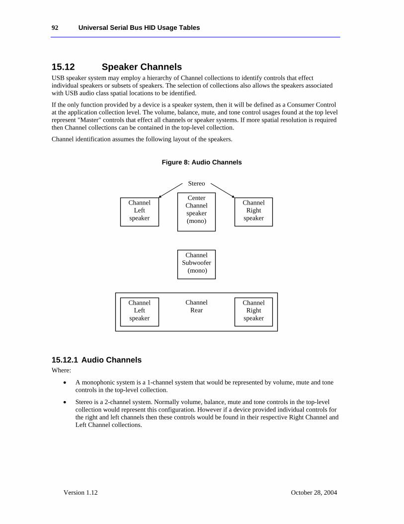
92 Universal Serial Bus HID Usage Tables
Version 1.12 October 28, 2004
15.12 Speaker Channels USB speaker system may employ a hierarchy of Channel collections to identify controls that effect individual speakers or subsets of speakers. The selection of collections also allows the speakers associated with USB audio class spatial locations to be identified.
If the only function provided by a device is a speaker system, then it will be defined as a Consumer Control at the application collection level. The volume, balance, mute, and tone control usages found at the top level represent "Master" controls that effect all channels or speaker systems. If more spatial resolution is required then Channel collections can be contained in the top-level collection.
Channel identification assumes the following layout of the speakers.
Figure 8: Audio Channels
15.12.1 Audio Channels Where:
• A monophonic system is a 1-channel system that would be represented by volume, mute and tone controls in the top-level collection.
• Stereo is a 2-channel system. Normally volume, balance, mute and tone controls in the top-level collection would represent this configuration. However if a device provided individual controls for the right and left channels then these controls would be found in their respective Right Channel and Left Channel collections.
Center Channel speaker (mono)
Channel Subwoofer
(mono)
Channel Left
speaker
Channel Right
speaker
Channel Rear
Channel Left
speaker
Channel Right
speaker
Stereo
Universal Serial Bus HID Usage Tables 93
Version 1.12 October 21, 2004
• Dolby Surround is a 3-channel system with Right, Left, and Rear Channels. This configuration is very similar to a stereo configuration however any controls that only effected the rear speakers would be found in a Surround Channel collection.
• Dolby Pro-Logic surround is a 4-channel system with Right, Left, Center, and Rear Channels. Similar to Dolby Surround however any controls that only effected the center speaker would be found in a Center Front Channel collection.
• Dolby Digital is a 6-channel system with 3 front channels (Right, Left and Center), 2 surround channels (Rear Right and Rear Right), and a Subwoofer (LFE) Channel. Similar to Dolby Pro-Logic however any controls that only effected the subwoofer speaker would be found in a Low Frequency Enhancement Channel collection.
In both implementations of Dolby Surround and Dolby Pro-Logic the Rear channel is actually a monophonic bandwidth-limited (7 kHz) channel that is often implemented as two separate speakers, right and left. Both speakers receive the same source.
Master or system-wide controls associated with all channel positions will be found in the top-level collection of the consumer control.
Speaker System CL – This collection is used to define controls that effect all channels of an individual speaker system if the device contains controls for more than one speaker system. Note that the controls defined in the top-level collection will be the true master controls, effecting all speaker systems. This collection can contain any of the following Channel collections.
Channel Left CL – A collection of controls associated with the Left channel.
Channel Right CL – A collection of controls associated with the Right channel.
Channel Center CL – A collection of controls associated with the Center channel.
Channel Front CL – A collection of controls associated with the Front channels. To provide more detail on controls, this collection may optionally contain Channel Left, Channel Right, and Channel Center collections The Audio class notation for this Channel Front(Channel Left) is L. The Audio class notation for this Channel Front(Channel Right) is R. The Audio class notation for this Channel Front(Channel Center) is C.
Channel Center Front CL – A collection of controls associated with the Center Front channels. To provide more detail on controls, this collection may optionally contain Channel Left and Channel Right collections The Audio class notation for this Channel Center Front(Channel Left) is LC (left of center in front). The Audio class notation for this Channel Center Front(Channel Right) is RC (right of center in front).
Channel Side CL – A collection of controls associated with the Side or wall channels. To provide more detail on controls, this collection may optionally contain Channel Left and Channel Right collections The Audio class notation for this Channel Side(Channel Le
Channel Surround CL – A collection of controls associated with the Surround channels. The Audio class notation for this Channel Surround is S. To provide more detail on controls, this collection may optionally contain Channel Left and Channel Right collections The Audio class notation for this Channel Surround(Channel Left) is LS. The Audio class notation for this Channel Surround(Channel Right) is RS.
94 Universal Serial Bus HID Usage Tables
Version 1.12 October 28, 2004
Channel Low Frequency Enhancement
CL – A collection of controls associated with the Low Frequency Enhancement or Subwoofer channel. The Audio class notation for this channel is LFE.
Channel Top CL – A collection of controls associated with the Top or overhead channel. The Audio class notation for this channel is T.
Channel Unknown CL – A collection of controls associated with an unknown channel position.
15.13 PC Theatre
Media Select SAP Sel - Select Tuner using Secondary Audio Program (SAP) information.
Sub-channel LC - Digital TV sub-channel selection control where the range of possible values is equal to the number of sub-channels supported by the device.
Sub-channel Increment OSC - Digital TV sub-channel control where each activation of the control increments the current sub-channel selection to the next available sub-channel.
Sub-channel Decrement OSC - Digital TV sub-channel control where each activation of the control decrements the current sub-channel selection to the next available sub-channel.
Alternate-audio Increment
OSC - Digital TV alternate-audio control where each activation of the control increments the current alternate-audio selection to the next available alternate-audio.
Alternate-audio Decrement
OSC - Digital TV alternate-audio control where each activation of the control decrements the current alternate-audio selection to the next available alternate-audio.
15.14 Programmable Buttons
Programmable Buttons
NAry - The user defines the function of these buttons to control software applications or GUI objects. The Programmable Buttons named array contains Button Page usages as selectors.
15.15 Application Launch Buttons These controls launch the application that most closely relates in function to the Usage Name. When a device containing these Usages is installed, software must configure which application is associated with each control. The hardware or operating system vendor can provide configuration tools for the user to assist in or change the configuration. The following Usages are provided for this purpose:
Application Launch Buttons
NAry - This array contains Application Launch (AL) selectors.
Universal Serial Bus HID Usage Tables 95
Version 1.12 October 21, 2004
AL Launch Button Configuration Tool
Sel - Used to associate buttons in an array of Launch Buttons with the application to be launched.
AL Programmable Button Configuration Tool
Sel - Used to associate Buttons in an array of Programmable Buttons with the function to be performed. An example would be a key programmed to play back a series of keystrokes.
AL Consumer Control Configuration Tool
Sel - Used to associate generic controls with a sepcific consumer device or software player to receive the control input, regardless of user focus. For example, a set of Transport Controls could be associated with a DVD-ROM player that would receive the Mute input even when it does not have the user focus.
AL Word Processor Sel - Launch word processor.
AL Text Editor Sel - Launch text editor.
AL Spreadsheet Sel - Launch spreadsheet application.
AL Graphics Editor Sel - Launch graphics editor.
AL Presentation App Sel - Launch presentation application.
AL Database App Sel - Launch database application.
AL Email Reader Sel - Launch email reader.
AL Newsreader Sel - Launch newsreader.
AL Voicemail Sel - Launch voicemail application.
AL Contacts/Address Book
Sel - Launch contact database manager or address book application.
AL Calendar/Schedule Sel - Launch calendar or schedule application.
AL Task/Project Manager
Sel - Launch task or project manager application.
AL Log/Journal/Timecard
Sel - Launch log, journal or timecard application.
AL Checkbook/Finance Sel - Launch checkbook or finance application.
AL Calculator Sel - Launch calculator.
AL A/V Capture/Playback
Sel - Launch A/V Capture or Playback application.
AL Local Machine Browser
Sel - Launch local machine browser.
AL LAN/WAN Browser
Sel - Launch LAN/WAN browser.
AL Internet Browser Sel - Launch internet browser.
AL Remote Networking/ISP Connect
Sel - Launch remote networking or ISP connection.
AL Network Conference
Sel - Launch network conference application.
96 Universal Serial Bus HID Usage Tables
Version 1.12 October 28, 2004
AL Network Chat Sel - Launch network chat application.
AL Telephony/Dialer Sel - Launch telephony or dialer application.
AL Logon Sel - Launch logon.
AL Logoff Sel - Launch logoff.
AL Logon/Logoff Sel - Launch logon or logoff depending on current state.
AL Terminal Lock/Screensaver
Sel - Launch terminal lock or screensaver.
AL Control Panel Sel - Launch control panel.
AL Command Line Processor/Run
Sel - Launch command line processor (Run).
AL Process/Task Manager
Sel - Launch process or task manager application.
AL Select Task/Application
Sel - Launch task or application selection application.
AL Next Task/Application
Sel - Go to next task or application.
AL Previous Task/Application
Sel - Go to previous task or application.
AL Preemptive Halt Task/Application
Sel - Initiate preemptive task/application halt.
AL Integrated Help Center
Sel - Launch a system wide, context-insensitive integrated help center.
AL Power Status Sel - Launch Power Status/Management application
AL Documents Sel - Launch Documents Browser application
AL Thesaurus Sel - Launch Thesaurus application
AL Dictionary Sel - Launch Dictionary application
AL Desktop Sel - Display Desktop (in a windowed environment)
AL Spell Check Sel - Launch Spell Check application
AL Grammar Check Sel - Launch Grammar Check application
AL Wireless Status Sel - Launch Wireless Status/Management application
AL Keyboard Layout Sel - Launch Keyboard Layout Management application
AL Virus Protection Sel - Launch Virus Protection application
AL Encryption Sel - Launch Encryption Management application
AL Screen Saver Sel - Launch Screen Saver application
AL Alarms Sel - Launch Timer/Alarm application
AL Clock Sel - Launch System Clock application
AL File Browser Sel - Launch System File Browser
AL Image Browser Sel - Launch Image Browser
Universal Serial Bus HID Usage Tables 97
Version 1.12 October 21, 2004
AL Audio Browser Sel - Launch Audio Browser
AL Movie Browser Sel - Launch Movie Browser
AL Digital Rights Manager
Sel - Launch Digital Rights Manager (DRM) application. This application allows users to manage digital rights or similar credentials that they have acquired or created. The focus of the credentials cache is authentication for use of digital media.
AL Digital Wallet Sel – Lanches the user's Digital Wallet manager. This application manages a store of credentials whose focus is online commerce.
AL Instant Messaging Sel – Launch the user’s Instant Messaging Application.
AL OEM Features/ Tips/Tutorial Browser
Sel - Launch web browser with URL or app specific to PC/Web Appliance/ Thin Client/ Set-top Box OEM that points out features, tips, and tutorials.
AL OEM Help Sel - Launch help file or online help specific to a PC system, thin client or terminal. Not specific to OS or specific application.
AL Online Community Sel - Launch web browser with URL specific to an online community.
AL Entertainment Content Browser
Sel - Launch web browser with URL specific to a site featuring music downloads, streaming video, web casts, entertainment news, and reviews.
AL Online Shopping Browser
Sel - Launch web browser with URL specific to an online store and a variety of leading product and services.
AL SmartCard Information/Help
Sel - Launch web browser with URL specific to SmartCard Information and Help
AL Market Monitor/Finance Browser
Sel - Launch web browser with URL specific to Market news or an application that allows a user to monitor market activity.
AL Customized Corporate News Browser
Sel - Launch web browser with URL specific to internal corporate news.
AL Online Activities Browser
Sel - Launch Online Activity browser. This usage would typically launch a web browser with a URL specific to a site featuring activities centered around the hardware package that included this button. i.e. a media center device would launch a web site that had activities centered around photo shooting, video shooting, camera product reviews, etc. A gaming machine would link the user to a website with gaming related reviews and news.
AL Research/Search Browser
Sel - Launch web browser with URL or app specific to doing research like an encyclopedia or thesaurus website or app,
AL Audio Player Sel - Launches an audio player. This audio player can play one or many audio formats.
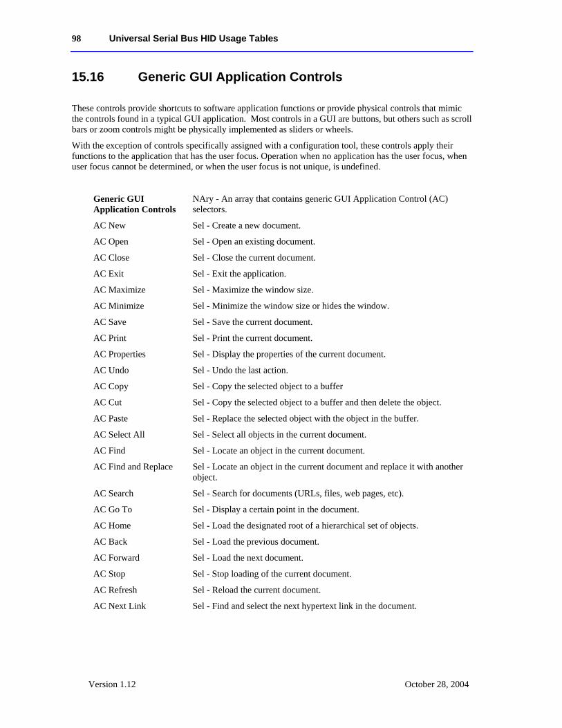
98 Universal Serial Bus HID Usage Tables
Version 1.12 October 28, 2004
15.16 Generic GUI Application Controls
These controls provide shortcuts to software application functions or provide physical controls that mimic the controls found in a typical GUI application. Most controls in a GUI are buttons, but others such as scroll bars or zoom controls might be physically implemented as sliders or wheels.
With the exception of controls specifically assigned with a configuration tool, these controls apply their functions to the application that has the user focus. Operation when no application has the user focus, when user focus cannot be determined, or when the user focus is not unique, is undefined.
Generic GUI Application Controls
NAry - An array that contains generic GUI Application Control (AC) selectors.
AC New Sel - Create a new document.
AC Open Sel - Open an existing document.
AC Close Sel - Close the current document.
AC Exit Sel - Exit the application.
AC Maximize Sel - Maximize the window size.
AC Minimize Sel - Minimize the window size or hides the window.
AC Save Sel - Save the current document.
AC Print Sel - Print the current document.
AC Properties Sel - Display the properties of the current document.
AC Undo Sel - Undo the last action.
AC Copy Sel - Copy the selected object to a buffer
AC Cut Sel - Copy the selected object to a buffer and then delete the object.
AC Paste Sel - Replace the selected object with the object in the buffer.
AC Select All Sel - Select all objects in the current document.
AC Find Sel - Locate an object in the current document.
AC Find and Replace Sel - Locate an object in the current document and replace it with another object.
AC Search Sel - Search for documents (URLs, files, web pages, etc).
AC Go To Sel - Display a certain point in the document.
AC Home Sel - Load the designated root of a hierarchical set of objects.
AC Back Sel - Load the previous document.
AC Forward Sel - Load the next document.
AC Stop Sel - Stop loading of the current document.
AC Refresh Sel - Reload the current document.
AC Next Link Sel - Find and select the next hypertext link in the document.
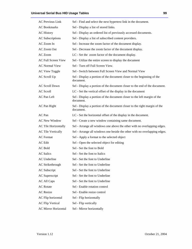
Universal Serial Bus HID Usage Tables 99
Version 1.12 October 21, 2004
AC Previous Link Sel - Find and select the next hypertext link in the document.
AC Bookmarks Sel - Display a list of stored links.
AC History Sel - Display an ordered list of previously accessed documents.
AC Subscriptions Sel - Display a list of subscribed content providers.
AC Zoom In Sel - Increase the zoom factor of the document display.
AC Zoom Out Sel - Decrease the zoom factor of the document display.
AC Zoom LC - Set the zoom factor of the document display.
AC Full Screen View Sel - Utilize the entire screen to display the document
AC Normal View Sel - Turn off Full Screen View.
AC View Toggle Sel - Switch between Full Screen View and Normal View
AC Scroll Up Sel - Display a portion of the document closer to the beginning of the document.
AC Scroll Down Sel - Display a portion of the document closer to the end of the document.
AC Scroll LC - Set the vertical offset of the display in the document
AC Pan Left Sel - Display a portion of the document closer to the left margin of the document.
AC Pan Right Sel - Display a portion of the document closer to the right margin of the document.
AC Pan LC - Set the horizontal offset of the display in the document.
AC New Window Sel - Create a new window containing same document.
AC Tile Horizontally Sel - Arrange all windows one above the other with no overlapping edges.
AC Tile Vertically Sel - Arrange all windows one beside the other with no overlapping edges.
AC Format Sel - Apply a format to the selected object
AC Edit Sel - Open the selected object for editing
AC Bold Sel - Set the font to Bold
AC Italics Sel - Set the font to Italics
AC Underline Sel - Set the font to Underline
AC Strikethrough Sel - Set the font to Underline
AC Subscript Sel - Set the font to Underline
AC Superscript Sel - Set the font to Underline
AC All Caps Sel - Set the font to Underline
AC Rotate Sel - Enable rotation control
AC Resize Sel - Enable resize control
AC Flip horizontal Sel - Flip horizontally
AC Flip Vertical Sel - Flip vertically
AC Mirror Horizontal Sel - Mirror horizontally
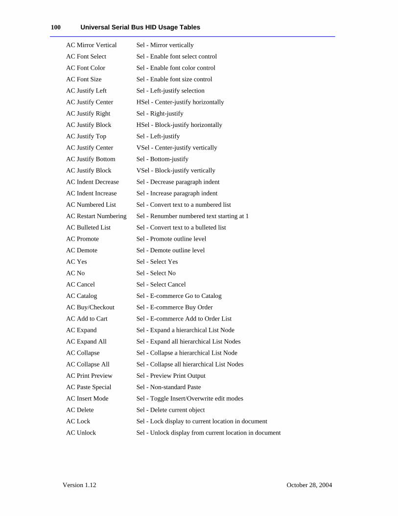
100 Universal Serial Bus HID Usage Tables
Version 1.12 October 28, 2004
AC Mirror Vertical Sel - Mirror vertically
AC Font Select Sel - Enable font select control
AC Font Color Sel - Enable font color control
AC Font Size Sel - Enable font size control
AC Justify Left Sel - Left-justify selection
AC Justify Center HSel - Center-justify horizontally
AC Justify Right Sel - Right-justify
AC Justify Block HSel - Block-justify horizontally
AC Justify Top Sel - Left-justify
AC Justify Center VSel - Center-justify vertically
AC Justify Bottom Sel - Bottom-justify
AC Justify Block VSel - Block-justify vertically
AC Indent Decrease Sel - Decrease paragraph indent
AC Indent Increase Sel - Increase paragraph indent
AC Numbered List Sel - Convert text to a numbered list
AC Restart Numbering Sel - Renumber numbered text starting at 1
AC Bulleted List Sel - Convert text to a bulleted list
AC Promote Sel - Promote outline level
AC Demote Sel - Demote outline level
AC Yes Sel - Select Yes
AC No Sel - Select No
AC Cancel Sel - Select Cancel
AC Catalog Sel - E-commerce Go to Catalog
AC Buy/Checkout Sel - E-commerce Buy Order
AC Add to Cart Sel - E-commerce Add to Order List
AC Expand Sel - Expand a hierarchical List Node
AC Expand All Sel - Expand all hierarchical List Nodes
AC Collapse Sel - Collapse a hierarchical List Node
AC Collapse All Sel - Collapse all hierarchical List Nodes
AC Print Preview Sel - Preview Print Output
AC Paste Special Sel - Non-standard Paste
AC Insert Mode Sel - Toggle Insert/Overwrite edit modes
AC Delete Sel - Delete current object
AC Lock Sel - Lock display to current location in document
AC Unlock Sel - Unlock display from current location in document
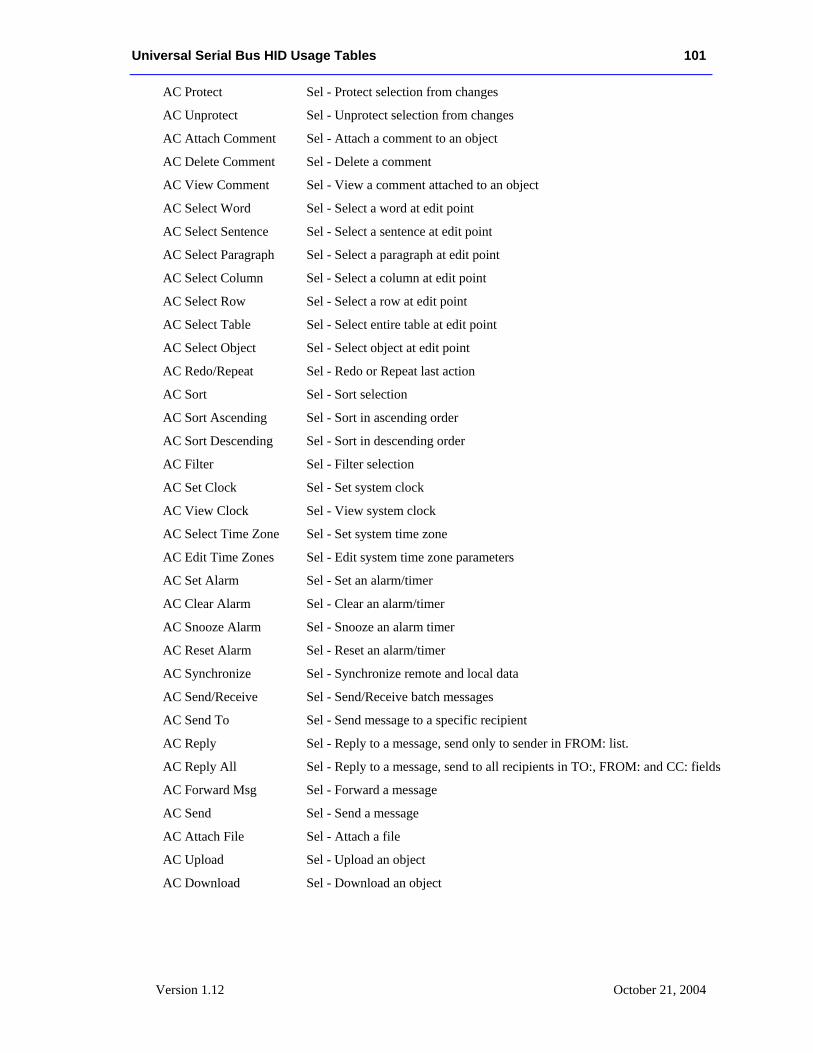
Universal Serial Bus HID Usage Tables 101
Version 1.12 October 21, 2004
AC Protect Sel - Protect selection from changes
AC Unprotect Sel - Unprotect selection from changes
AC Attach Comment Sel - Attach a comment to an object
AC Delete Comment Sel - Delete a comment
AC View Comment Sel - View a comment attached to an object
AC Select Word Sel - Select a word at edit point
AC Select Sentence Sel - Select a sentence at edit point
AC Select Paragraph Sel - Select a paragraph at edit point
AC Select Column Sel - Select a column at edit point
AC Select Row Sel - Select a row at edit point
AC Select Table Sel - Select entire table at edit point
AC Select Object Sel - Select object at edit point
AC Redo/Repeat Sel - Redo or Repeat last action
AC Sort Sel - Sort selection
AC Sort Ascending Sel - Sort in ascending order
AC Sort Descending Sel - Sort in descending order
AC Filter Sel - Filter selection
AC Set Clock Sel - Set system clock
AC View Clock Sel - View system clock
AC Select Time Zone Sel - Set system time zone
AC Edit Time Zones Sel - Edit system time zone parameters
AC Set Alarm Sel - Set an alarm/timer
AC Clear Alarm Sel - Clear an alarm/timer
AC Snooze Alarm Sel - Snooze an alarm timer
AC Reset Alarm Sel - Reset an alarm/timer
AC Synchronize Sel - Synchronize remote and local data
AC Send/Receive Sel - Send/Receive batch messages
AC Send To Sel - Send message to a specific recipient
AC Reply Sel - Reply to a message, send only to sender in FROM: list.
AC Reply All Sel - Reply to a message, send to all recipients in TO:, FROM: and CC: fields
AC Forward Msg Sel - Forward a message
AC Send Sel - Send a message
AC Attach File Sel - Attach a file
AC Upload Sel - Upload an object
AC Download Sel - Download an object
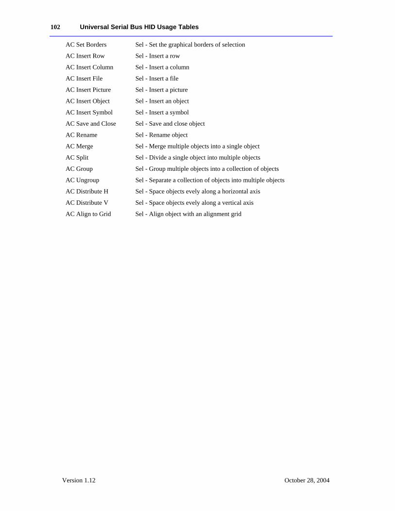
102 Universal Serial Bus HID Usage Tables
Version 1.12 October 28, 2004
AC Set Borders Sel - Set the graphical borders of selection
AC Insert Row Sel - Insert a row
AC Insert Column Sel - Insert a column
AC Insert File Sel - Insert a file
AC Insert Picture Sel - Insert a picture
AC Insert Object Sel - Insert an object
AC Insert Symbol Sel - Insert a symbol
AC Save and Close Sel - Save and close object
AC Rename Sel - Rename object
AC Merge Sel - Merge multiple objects into a single object
AC Split Sel - Divide a single object into multiple objects
AC Group Sel - Group multiple objects into a collection of objects
AC Ungroup Sel - Separate a collection of objects into multiple objects
AC Distribute H Sel - Space objects evely along a horizontal axis
AC Distribute V Sel - Space objects evely along a vertical axis
AC Align to Grid Sel - Align object with an alignment grid
Universal Serial Bus HID Usage Tables 103
Version 1.12 October 21, 2004
16 Digitizers (0x0D) This section provides detailed descriptions of the usages employed by Digitizer Devices.
Table 18: Digitizer Page
Usage ID Usage Name Usage Types Section
00 Undefined
01 Digitizer CA 16.1
02 Pen CA 16.1
03 Light Pen CA 16.1
04 Touch Screen CA 16.1
05 Touch Pad CA 16.1
06 White Board CA 16.1
07 Coordinate Measuring Machine
CA 16.1
08 3D Digitizer CA 16.1
09 Stereo Plotter CA 16.1
0A Articulated Arm CA 16.1
0B Armature CA 16.1
0C Multiple Point Digitizer CA 16.1
0D Free Space Wand CA 16.1
0E-1F Reserved
20 Stylus CL 16.2
21 Puck CL 16.2
22 Finger CL 16.2
23-2F Reserved
30 Tip Pressure DV 16.3.1
31 Barrel Pressure DV 16.3.1
32 In Range MC 16.3.1
33 Touch MC 16.3.1
34 Untouch OSC 16.3.1
35 Tap OSC 16.3.1
36 Quality DV 16.3.1
37 Data Valid MC 16.3.1
38 Transducer Index DV 16.3.1
39 Tablet Function Keys CL 16.3.1
3A Program Change Keys CL 16.3.1
3B Battery Strength DV 16.3.1
3C Invert MC 16.3.1
3D X Tilt DV 16.3.2
3E Y Tilt DV 16.3.2
104 Universal Serial Bus HID Usage Tables
Version 1.12 October 28, 2004
Usage ID Usage Name Usage Types Section
3F Azimuth DV 16.3.3
40 Altitude DV 16.3.3
41 Twist DV 16.3.3
42 Tip Switch MC 16.4
43 Secondary Tip Switch MC 16.4
44 Barrel Switch MC 16.4
45 Eraser MC 16.4
46 Tablet Pick MC 16.4
47-FFFF Reserved
16.1 Digitizer Devices Digitizer CA – A device that measures absolute spatial position, typically in two or
more dimensions. This is a generic usage; several specialized types of digitizers are distinguished by their attributes.
Pen CA – A digitizer with an integrated display that allows use of a stylus. The system must ensure that the sensed stylus position and the display representations of that position are the same. A pen digitizer has enough time and space resolution for handwriting input. A digitizer that may or may not be in an integrated display application should use the more generic Digitizer collection usage.
Light Pen CA – A display-integrated digitizer that relies on the underlying video raster to determine position. The interpretation of light pen coordinates is sensitive to changes of display mode.
Touch Screen CA – A digitizer with an integrated display that allows the use of a finger or stylus for pointing. Some touch-screen technologies can differentiate between the touch of a finger and the touch of a stylus.
Touch Pad CA – A digitizer that is not integrated with a display, but allows the use of a finger for pointing.
White Board CA – A digitizer that is mounted vertically and can optionally be synchronized with a projected video display.
Coordinate Measuring Machine
CA – A specialized digitizing instrument that is used to make spatial measurements of maps or photographic images. It is not suitable for screen pointing.
3D Digitizer CA – General usage for a digitizer that measures position(s) in three-dimensional space.
Stereo Plotter CA – A 3D digitizer that relies on the operator’s binocular vision to determine the position of points on a stereoscopically rendered image.
Articulated Arm CA – A 3D digitizer that uses a series of instrumented mechanical linkages to determine the position of its tip in space.
Armature CA – A 3D digitizer that determines the position of several mechanical linkages in space. An armature typically represents the position of a human body for animation or modeling.
Universal Serial Bus HID Usage Tables 105
Version 1.12 October 21, 2004
Multiple Point Digitizer
CA – A 3D digitizer that detects the position of multiple points in space, typically through some non-mechanical means such as electromagnetic sensors.
Free Space Wand CA – A 3D digitizer that detects the position of a point at the end of a hand-held wand.
16.2 Digitizer Transducer Collection Usages Stylus CL – A stylus is a hand-held transducer that looks and is used like a pen. A
digitizer typically reports the coordinates of the tip of a stylus. The Stylus collection is a physical collection containing all the controls physically located on the stylus. In the Stylus collection a Pointer physical collection will contain the axes reported by the stylus.
Puck CL – A puck, sometimes called a cursor, is a mouse-like transducer that rests on a low friction surface. A digitizer typically reports the coordinates of crosshairs marked on the puck. The Puck collection is a logical collection containing all the controls located on the puck. In the Puck collection a Pointer physical collection will contain the axes reported by the puck.
Finger CL – Any human appendage used as a transducer, such as a finger touching a touch screen to set the location of the screen cursor. A digitizer typically reports the coordinates of center of the finger. In the Finger collection a Pointer physical collection will contain the axes reported by the finger.
16.3 Digitizer Report Field Usages Not all digitizer field usages are from the Digitizer usage page. In particular, the usages for X and Y displacement come from the Generic Desktop page.
16.3.1 Digitizer-Specific Fields Tip Pressure DV – Force exerted against the tablet surface by the transducer, typically a
stylus.
Barrel Pressure DV – Force exerted directly by the user on a transducer sensor, such as a pressure-sensitive button on the barrel of a stylus.
In Range MC – Indicates that a transducer is located within the region where digitizing is possible. In Range is a bit quantity.
Touch MC – A bit quantity for touch pads analogous to In Range that indicates that a finger is touching the pad. A system will typically map a Touch usage to a primary button.
Untouch OSC – Indicates the release of a finger from the surface of the touch screen. A system typically maps an Untouch usage to the release of a primary button.
Tap OSC – On a touch pad, indicates that the finger has been quickly lifted and replaced on the tablet surface. This is typically mapped to a button event, but is distinct as no physical button is involved.
Quality DV – If set, indicates that the transducer is sensed to be in a relatively noise-free region of digitizing.
Data Valid MC – Indicates that the current data set is valid.
106 Universal Serial Bus HID Usage Tables
Version 1.12 October 28, 2004
Transducer Index DV – Indicates which transducer generated the current report. Transducer Index is useful if multiple transducers generate identical reports. Otherwise, report IDs should be used to distinguish different transducer types.
Tablet Function Keys CL – These controls are located on the surface of a digitizing tablet, and may be implemented as actual switches, or as soft keys actuated by the digitizing transducer. These are often used to trigger location-independent macros or other events.
Program Change Keys
CL – Specialized function key targets that change some internal aspect of the digitizer’s behavior.
Battery Strength DV – Indicates the amount of power remaining in a digitizer component that is outside the scope of device power management. Typically this is the battery for a cordless transducer.
Invert MC – A bit that indicates that the currently sensed position originates from the end of a stylus opposite the tip.
16.3.2 Tilt Orientation X Tilt and Y Tilt are used together to specify the tilt away from normal of a digitizer transducer. In its normal position, the values of X Tilt and Y Tilt for a transducer are both zero. The X Tilt/Y Tilt orientation of a system does not specify the rotation of the transducer around its own normal axis.
X Tilt DV – This quantity is used in conjunction with Y Tilt to represent the tilt away from normal of a transducer, such as a stylus. The X Tilt value represents the plane angle between the Y-Z plane and the plane containing the transducer axis and the Y axis. A positive X Tilt is to the right.
Y Tilt DV – This value represents the angle between the X-Z and transducer-X planes. A positive Y Tilt is toward the user.
16.3.3 Azimuth-Altitude Orientation Azimuth-altitude is an alternative to the tilt system of specifying a digitizer transducer’s orientation. This system includes rotation of the transducer around its own axis.
Azimuth DV – Specifies the counter-clockwise rotation of the cursor around the Z axis through a full circular range.
Altitude DV – Specifies the angle with the X-Y plane through a signed, semicircular range. Positive values specify an angle downward and toward the positive Z axis.
Twist DV – Specifies the clockwise rotation of the cursor around its own major axis.
Universal Serial Bus HID Usage Tables 107
Version 1.12 October 21, 2004
16.4 Digitizer Switch Usages Tip Switch MC – A switch located at the tip of a stylus, indicating contact of the stylus
with a surface. A pen-based system or system extension would use this switch to enable the input of handwriting or gesture data. The system typically maps Tip Switch to a primary button in a non-pen context.
Secondary Tip Switch MC – A secondary switch used in conjunction with Tip Switch to indicate pressure above a certain threshold applied with the stylus. The threshold switch is not closed unless the tip switch already is.
Barrel Switch MC – A non-tip button located on the barrel of a stylus. Its function is typically mapped to a system secondary button or to a Shift key modifier that changes the Tip Switch function from primary button to secondary button.
Eraser MC – This control is used for erasing objects. Following the metaphor of a pencil, it is typically located opposite the writing end of a stylus. It may be a bit switch or a pressure quantity.
Tablet Pick MC – The primary button used by CAD systems, typically to select an object. Sometimes called Button Zero.
108 Universal Serial Bus HID Usage Tables
Version 1.12 October 28, 2004
17 Unicode Page (0x10) The Unicode Page directly maps to the two-octet form defined in the Unicode Standard.
The Unicode Standard, Version 1.1, is the newest version of the Unicode™ Standard. Unicode 1.1 includes the changes and additions that were made to Unicode 1.0 in the process of alignment with the international character encoding standard, ISO/IEC 10646-1, which was approved by ISO/IEC as an International Standard in June 1992, and published in May 1993. The character content and encoding of Unicode 1.1 is thus identical to that of the ISO/IEC 10646-1 UCS-2 (the two-octet form). See Section 18, “Alphanumeric Display Page (0x14),” for an example.
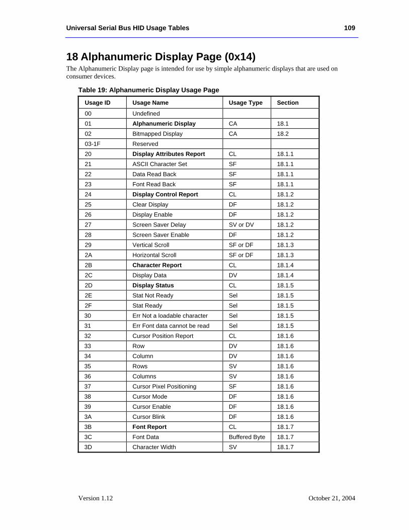
Universal Serial Bus HID Usage Tables 109
Version 1.12 October 21, 2004
18 Alphanumeric Display Page (0x14) The Alphanumeric Display page is intended for use by simple alphanumeric displays that are used on consumer devices.
Table 19: Alphanumeric Display Usage Page
Usage ID Usage Name Usage Type Section
00 Undefined
01 Alphanumeric Display CA 18.1
02 Bitmapped Display CA 18.2
03-1F Reserved
20 Display Attributes Report CL 18.1.1
21 ASCII Character Set SF 18.1.1
22 Data Read Back SF 18.1.1
23 Font Read Back SF 18.1.1
24 Display Control Report CL 18.1.2
25 Clear Display DF 18.1.2
26 Display Enable DF 18.1.2
27 Screen Saver Delay SV or DV 18.1.2
28 Screen Saver Enable DF 18.1.2
29 Vertical Scroll SF or DF 18.1.3
2A Horizontal Scroll SF or DF 18.1.3
2B Character Report CL 18.1.4
2C Display Data DV 18.1.4
2D Display Status CL 18.1.5
2E Stat Not Ready Sel 18.1.5
2F Stat Ready Sel 18.1.5
30 Err Not a loadable character Sel 18.1.5
31 Err Font data cannot be read Sel 18.1.5
32 Cursor Position Report CL 18.1.6
33 Row DV 18.1.6
34 Column DV 18.1.6
35 Rows SV 18.1.6
36 Columns SV 18.1.6
37 Cursor Pixel Positioning SF 18.1.6
38 Cursor Mode DF 18.1.6
39 Cursor Enable DF 18.1.6
3A Cursor Blink DF 18.1.6
3B Font Report CL 18.1.7
3C Font Data Buffered Byte 18.1.7
3D Character Width SV 18.1.7
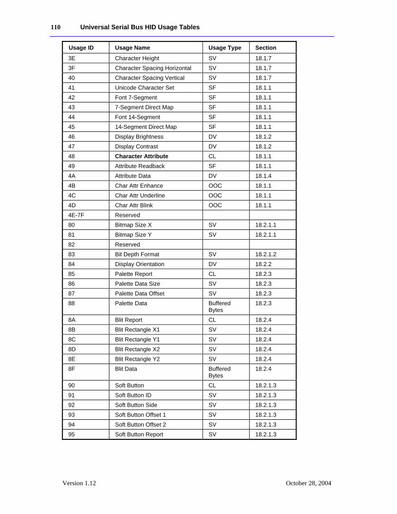
110 Universal Serial Bus HID Usage Tables
Version 1.12 October 28, 2004
Usage ID Usage Name Usage Type Section
3E Character Height SV 18.1.7
3F Character Spacing Horizontal SV 18.1.7
40 Character Spacing Vertical SV 18.1.7
41 Unicode Character Set SF 18.1.1
42 Font 7-Segment SF 18.1.1
43 7-Segment Direct Map SF 18.1.1
44 Font 14-Segment SF 18.1.1
45 14-Segment Direct Map SF 18.1.1
46 Display Brightness DV 18.1.2
47 Display Contrast DV 18.1.2
48 Character Attribute CL 18.1.1
49 Attribute Readback SF 18.1.1
4A Attribute Data DV 18.1.4
4B Char Attr Enhance OOC 18.1.1
4C Char Attr Underline OOC 18.1.1
4D Char Attr Blink OOC 18.1.1
4E-7F Reserved
80 Bitmap Size X SV 18.2.1.1
81 Bitmap Size Y SV 18.2.1.1
82 Reserved
83 Bit Depth Format SV 18.2.1.2
84 Display Orientation DV 18.2.2
85 Palette Report CL 18.2.3
86 Palette Data Size SV 18.2.3
87 Palette Data Offset SV 18.2.3
88 Palette Data Buffered Bytes
18.2.3
8A Blit Report CL 18.2.4
8B Blit Rectangle X1 SV 18.2.4
8C Blit Rectangle Y1 SV 18.2.4
8D Blit Rectangle X2 SV 18.2.4
8E Blit Rectangle Y2 SV 18.2.4
8F Blit Data Buffered Bytes
18.2.4
90 Soft Button CL 18.2.1.3
91 Soft Button ID SV 18.2.1.3
92 Soft Button Side SV 18.2.1.3
93 Soft Button Offset 1 SV 18.2.1.3
94 Soft Button Offset 2 SV 18.2.1.3
95 Soft Button Report SV 18.2.1.3
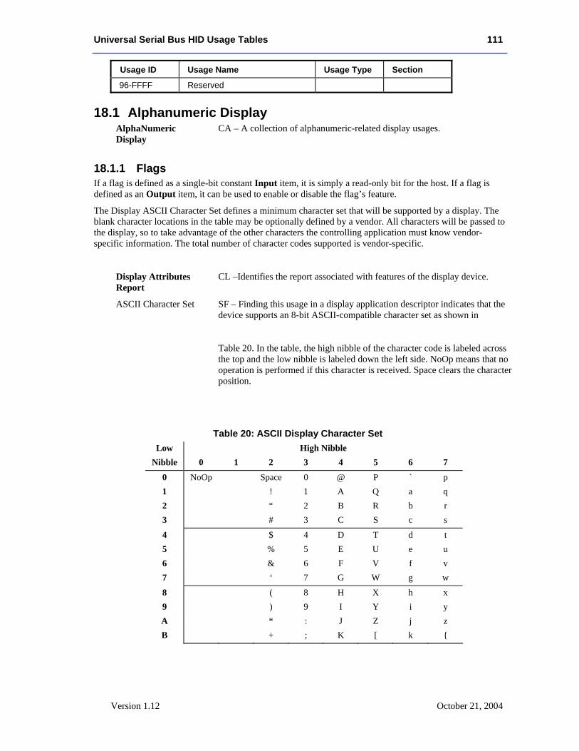
Universal Serial Bus HID Usage Tables 111
Version 1.12 October 21, 2004
Usage ID Usage Name Usage Type Section
96-FFFF Reserved
18.1 Alphanumeric Display AlphaNumeric Display
CA – A collection of alphanumeric-related display usages.
18.1.1 Flags If a flag is defined as a single-bit constant Input item, it is simply a read-only bit for the host. If a flag is defined as an Output item, it can be used to enable or disable the flag’s feature.
The Display ASCII Character Set defines a minimum character set that will be supported by a display. The blank character locations in the table may be optionally defined by a vendor. All characters will be passed to the display, so to take advantage of the other characters the controlling application must know vendor-specific information. The total number of character codes supported is vendor-specific.
Display Attributes Report
CL –Identifies the report associated with features of the display device.
ASCII Character Set SF – Finding this usage in a display application descriptor indicates that the device supports an 8-bit ASCII-compatible character set as shown in
Table 20. In the table, the high nibble of the character code is labeled across the top and the low nibble is labeled down the left side. NoOp means that no operation is performed if this character is received. Space clears the character position.
Table 20: ASCII Display Character Set Low High Nibble
Nibble 0 1 2 3 4 5 6 7
0 NoOp Space 0 @ P ` p 1 ! 1 A Q a q 2 “ 2 B R b r 3 # 3 C S c s
4 $ 4 D T d t 5 % 5 E U e u 6 & 6 F V f v 7 ‘ 7 G W g w
8 ( 8 H X h x 9 ) 9 I Y i y A * : J Z j z B + ; K [ k {
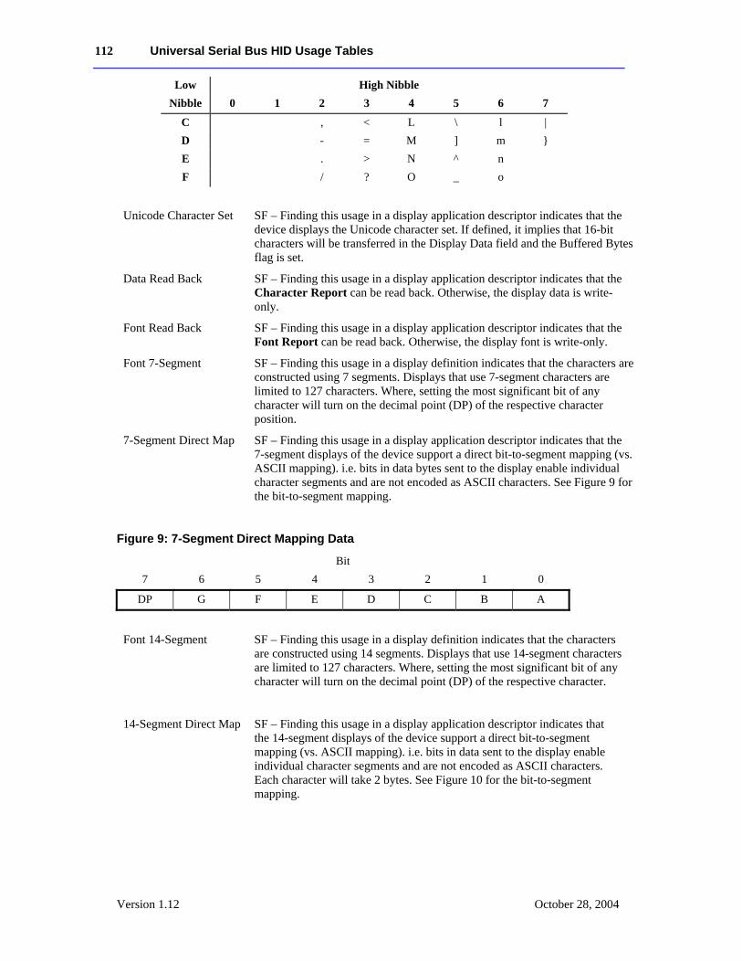
112 Universal Serial Bus HID Usage Tables
Version 1.12 October 28, 2004
Low High Nibble Nibble 0 1 2 3 4 5 6 7
C , < L \ l | D - = M ] m } E . > N ^ n F / ? O _ o
Unicode Character Set SF – Finding this usage in a display application descriptor indicates that the device displays the Unicode character set. If defined, it implies that 16-bit characters will be transferred in the Display Data field and the Buffered Bytes flag is set.
Data Read Back SF – Finding this usage in a display application descriptor indicates that the Character Report can be read back. Otherwise, the display data is write-only.
Font Read Back SF – Finding this usage in a display application descriptor indicates that the Font Report can be read back. Otherwise, the display font is write-only.
Font 7-Segment SF – Finding this usage in a display definition indicates that the characters are constructed using 7 segments. Displays that use 7-segment characters are limited to 127 characters. Where, setting the most significant bit of any character will turn on the decimal point (DP) of the respective character position.
7-Segment Direct Map SF – Finding this usage in a display application descriptor indicates that the 7-segment displays of the device support a direct bit-to-segment mapping (vs. ASCII mapping). i.e. bits in data bytes sent to the display enable individual character segments and are not encoded as ASCII characters. See Figure 9 for the bit-to-segment mapping.
Figure 9: 7-Segment Direct Mapping Data
Bit 7 6 5 4 3 2 1 0
DP G F E D C B A
Font 14-Segment SF – Finding this usage in a display definition indicates that the characters are constructed using 14 segments. Displays that use 14-segment characters are limited to 127 characters. Where, setting the most significant bit of any character will turn on the decimal point (DP) of the respective character.
14-Segment Direct Map SF – Finding this usage in a display application descriptor indicates that the 14-segment displays of the device support a direct bit-to-segment mapping (vs. ASCII mapping). i.e. bits in data sent to the display enable individual character segments and are not encoded as ASCII characters. Each character will take 2 bytes. See Figure 10 for the bit-to-segment mapping.
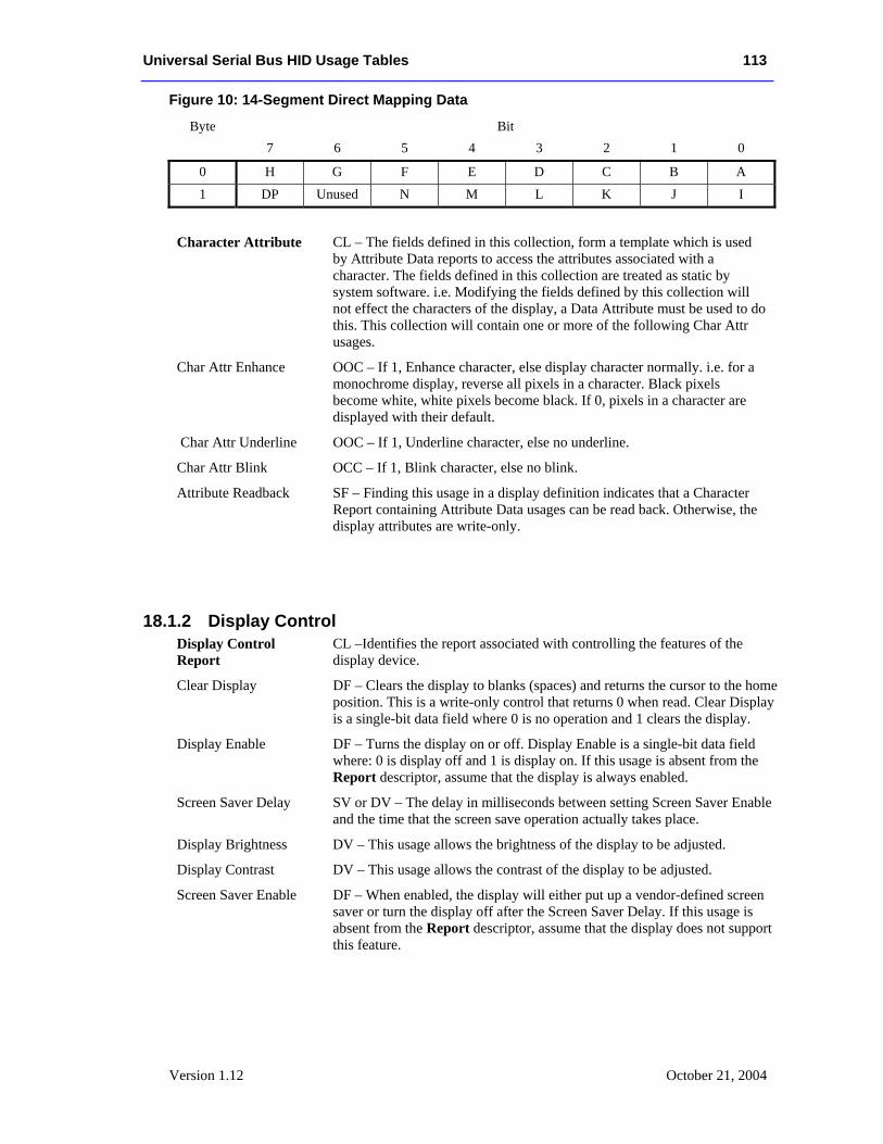
Universal Serial Bus HID Usage Tables 113
Version 1.12 October 21, 2004
Figure 10: 14-Segment Direct Mapping Data
Byte Bit 7 6 5 4 3 2 1 0
0 H G F E D C B A 1 DP Unused N M L K J I
Character Attribute CL – The fields defined in this collection, form a template which is used by Attribute Data reports to access the attributes associated with a character. The fields defined in this collection are treated as static by system software. i.e. Modifying the fields defined by this collection will not effect the characters of the display, a Data Attribute must be used to do this. This collection will contain one or more of the following Char Attr usages.
Char Attr Enhance OOC – If 1, Enhance character, else display character normally. i.e. for a monochrome display, reverse all pixels in a character. Black pixels become white, white pixels become black. If 0, pixels in a character are displayed with their default.
Char Attr Underline OOC – If 1, Underline character, else no underline.
Char Attr Blink OCC – If 1, Blink character, else no blink.
Attribute Readback SF – Finding this usage in a display definition indicates that a Character Report containing Attribute Data usages can be read back. Otherwise, the display attributes are write-only.
18.1.2 Display Control Display Control Report
CL –Identifies the report associated with controlling the features of the display device.
Clear Display DF – Clears the display to blanks (spaces) and returns the cursor to the home position. This is a write-only control that returns 0 when read. Clear Display is a single-bit data field where 0 is no operation and 1 clears the display.
Display Enable DF – Turns the display on or off. Display Enable is a single-bit data field where: 0 is display off and 1 is display on. If this usage is absent from the Report descriptor, assume that the display is always enabled.
Screen Saver Delay SV or DV – The delay in milliseconds between setting Screen Saver Enable and the time that the screen save operation actually takes place.
Display Brightness DV – This usage allows the brightness of the display to be adjusted.
Display Contrast DV – This usage allows the contrast of the display to be adjusted.
Screen Saver Enable DF – When enabled, the display will either put up a vendor-defined screen saver or turn the display off after the Screen Saver Delay. If this usage is absent from the Report descriptor, assume that the display does not support this feature.
114 Universal Serial Bus HID Usage Tables
Version 1.12 October 28, 2004
18.1.3 Scrolling If Horizontal Scrolling and Vertical Scrolling are disabled, characters received after the cursor reaches the right-most column (Column = Columns) will overwrite each other.
There are three scrolling modes: none, horizontal and vertical. Only one mode can be operative at a time. That is, Horizontal Scrolling and Vertical Scrolling are mutually exclusive.
• When Vertical Scrolling is enabled, if the cursor is on the last character of a row (Column = Columns) other than the last row (Row != Rows), the next character received will cause the vertical cursor position to be incremented (Row++) and the horizontal cursor position to be set to 0 (Column = 0). If the cursor is on the last character (Column = Columns) of the last row (Row = Rows), the next character will cause all rows to be scrolled up, the last row to be cleared, and the horizontal cursor position to be set to 0 (Column = 0).
• When Horizontal Scrolling is enabled, if the cursor is on the last character of a row (Column = Columns), the next character received will cause the row to be scrolled horizontally one character position and the character to be placed on the last column of the row.
Any data that scrolls off the display is lost.
Vertical Scroll or Horizontal Scroll are considered to be Static Flags (SF). That is, if they are not declared, it can be assumed that the mode is not supported. However, if they are defined as Dynamic Flags then the modes can be enabled or disabled.
Vertical Scroll SF – Indicates whether the display will scroll vertically, where 0 means that the display will not scroll vertically and 1 means that the display will scroll vertically.
Horizontal Scroll SF – Indicates whether the row will scroll horizontally, where 0 means that the display will not scroll horizontally and 1 means that the display will scroll horizontally.
18.1.4 Character Transfers An alphanumeric display can be configured to read or write multiple characters in a single message.
Character Report CL – Identifies the report associated with character data movement. Flow control is handled by the display NAKing Character reports until it is ready for more characters.
Display Data DV – The report field that is written to pass characters to the display. When read, the character currently indicated by the cursor is returned.
If this field is declared with a Report Count greater than 1, any characters not defined as NoOp will be written to the display. When the same field is read, all characters from the current cursor position forward will be returned. If the range goes beyond the end of the display memory, NoOp characters will be returned.
Buffered Byte – When the Display Data field is declared as Buffered Byte, the data in the array is used as an index in to the character ROM of the device. The Report Size will reflect the size of the character set supported by the device.
NAry – If a vendor wishes to identify specific characters other than those found in the ASCII character set and does not want to send 16-bit Unicode characters to the display, the vendor can describe the Display Data field as an
Universal Serial Bus HID Usage Tables 115
Version 1.12 October 21, 2004
Named Array (NAry) in which the Selector usages are pulled from the Unicode page.
Attribute Data DV – Writing to this field will modify the attribute values of the character currently indicated by the current cursor. When read, the attribute values of the character currently indicated by the cursor are returned.
This usage is always used in combination with a Display Data usage.
If this usage is declared, a Attribute Display collection must also be declared to define its contents. The Report Size of this field will reflect the size of the data fields as defined in the Attribute Display collection.
If this usage is declared with a Report Count greater than 1, the attributes of multiple characters can be changed simultaneoulsy, starting from the current cursor position. If the Attribute Read Back usage is declared, then the attributes of the characters from the current cursor position forward will be returned when this report is read. If the range goes beyond the end of the display memory, zero data will be returned.
18.1.5 Display Status A display will initially generate a Stat Not Ready status until the display is fully initialized. No commands should be issued to the display until the Stat Ready condition is detected. Any error will be held in Display Status field until it is read, at which point the Display Status field will return to the Stat Ready condition or be set to the next error code.
Display Status NAry – This is a collection of the status codes that the display supports. The status codes are reported in a single location array.
Stat Not Ready Sel – The display is not ready for use. These displays are typically slow to initialize.
Stat Ready Sel – The display is ready for use. No commands can be issued until the Display Status indicates Stat Ready.
Err Not a loadable character
Sel – This error will occur after an attempt is made to load a character from a non-loadable character location.
Err Font data cannot be read
Sel – This error will occur after an attempt is made to read the font bitmap of a character location that the display does not support.
18.1.6 Cursor Control There are two ways of handling cursor positioning:
• The Row and Column fields may be declared with a Report ID that is different from that used by the Data field. This will allow the cursor to be positioned independently of writing characters to the display.
• The Row, Column, and Data can all be in the same report. If either the Row or Column field contains an out-of-range value, the cursor position will not be updated.
116 Universal Serial Bus HID Usage Tables
Version 1.12 October 28, 2004
In a Display device, the cursor position is applied first, then any characters are written to the display buffer. Reading the Row and Column will provide the current cursor position.
If Cursor Mode is set to increment (1), nothing will happen if a character is entered when the cursor is on the last column of the last row. If a character is entered when the cursor is on the last column of any other row, the cursor will move to the first column of the next row.
If Cursor Mode is set to decrement (0), nothing will happen if a character is entered when the cursor is on the first column of the first row. If a character is entered when the cursor is on the first column of any other row, the cursor will move to the last column of the next row.
Cursor Position Report
CL –Identifies the report associated with cursor positioning.
Row DV – Identifies or sets the vertical character position of the cursor. A value of 0 is the topmost row.
Column DV – Identifies or sets the horizontal character position of the cursor. A value of 0 is the leftmost column.
Rows SV – Identifies the number of rows supported by the display.
Columns SV – Identifies the number of columns supported by the display.
Cursor Pixel Positioning
SF – Indicates that the display supports pixel-level cursor positioning. Cursor Pixel Positioning is a single-bit data field where 1 means that cursor pixel positioning is enabled and 0 means that character cursor positioning is enabled. If this usage is absent, assume that the display only supports character-level positioning.
If pixel positioning is supported but character positioning is enabled, Character Width plus Character Spacing Horizontal indicate the number of pixels the cursor will move horizontally and Character Height plus Character Spacing Vertical indicate the number of pixels the cursor will move vertically.
Note: If pixel positioning is supported, the Row and Column fields must be large enough to contain either a character or pixel address.
Cursor Mode DF – Sets the cursor movement direction. After each character code is sent to the display, the cursor can automatically move either right or left. Cursor Mode is a single-bit data field where 0 decrements the cursor position (moves left) and 1 increments the cursor position (moves right). If this usage is absent from the Report descriptor, assume that the cursor position is always incremented.
Cursor Enable DF – Turns the cursor on or off. Cursor Enable is a single-bit data field where 0 turns the cursor off and 1 turns the cursor on. If this usage is absent from the Report descriptor, assume that the cursor is always enabled.
Cursor Blink DF – Turns the cursor blinking on or off. Cursor Blink is a single-bit data field where 0 turns blinking off and 1 turns blinking on. If this usage is absent from the Report descriptor, assume that cursor blinking is off.
Universal Serial Bus HID Usage Tables 117
Version 1.12 October 21, 2004
18.1.7 Font Loading Alphanumeric displays that support loadable fonts will contain the usages described in this section.
To download a font, the report must contain the character code of the destination character and a buffered-bytes data field that contains Character Width times Character Height bits of data.
Font Data is organized as sequential rows of pixels where the least significant bit contains the pixel in the upper right corner of the character.
Not all displays support downloading of all character locations, so the Display Status field should be checked after each download to ensure that the operation completed successfully. An “Err Not a loadable character” value will be returned in the Display Status field if an error occurred.
Not all displays support uploading of all character locations so the Display Status field should be checked after each upload to ensure that the operation completed successfully. An “Err Font data cannot be read” value will be returned in the Display Status field if an error occurred.
Font Report CL – Finding this usage in a display application descriptor indicates that the display supports downloadable fonts. This usage is applied to a logical collection that defines the font download report.
Font Data A buffered-bytes data field that contains the font data.
The following usages define display parameters. These are normally static values defined in a Feature report.
The Character Spacing Horizontal and Character Spacing Vertical values indicate whether the inter-character spacing must be included in the downloaded font character or whether it is automatically set by the physical pixel layout of the display. A Character Spacing of 0 implies that any inter-character spacing must be included in the downloaded font. If a Character Spacing (Horizontal or Vertical) usage is not declared, it can be assumed that the respective inter-character spacing is forced by the physical pixel layout of the display and Character Spacing can therefore be assumed to be 1.
Character Width SV – Identifies the width of a character in pixels.
Character Height SV – Identifies the height of a character in pixels.
Character Spacing Horizontal
SV – Identifies the horizontal distance between characters in pixels.
Character Spacing Vertical
SV – Identifies the vertical distance between characters in pixels.
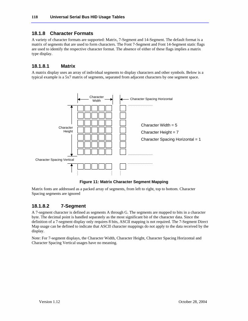
118 Universal Serial Bus HID Usage Tables
Version 1.12 October 28, 2004
18.1.8 Character Formats A variety of character formats are supported: Matrix, 7-Segment and 14-Segment. The default format is a matrix of segments that are used to form characters. The Font 7-Segment and Font 14-Segment static flags are used to identify the respective character format. The absence of either of these flags implies a matrix type display.
18.1.8.1 Matrix A matrix display uses an array of individual segments to display characters and other symbols. Below is a typical example is a 5x7 matrix of segments, separated from adjacent characters by one segment space.
Figure 11: Matrix Character Segment Mapping
Matrix fonts are addressed as a packed array of segments, from left to right, top to bottom. Character Spacing segments are ignored
18.1.8.2 7-Segment A 7-segment character is defined as segments A through G. The segments are mapped to bits in a character byte. The decimal point is handled separately as the most significant bit of the character data. Since the definition of a 7-segment display only requires 8 bits, ASCII mapping is not required. The 7-Segment Direct Map usage can be defined to indicate that ASCII character mappings do not apply to the data received by the display.
Note: For 7-segment displays, the Character Width, Character Height, Character Spacing Horizontal and Character Spacing Vertical usages have no meaning.
Character Spacing Horizontal
Character Height
Character Spacing Vertical
Character Width
Character Width = 5
Character Height = 7
Character Spacing Horizontal = 1
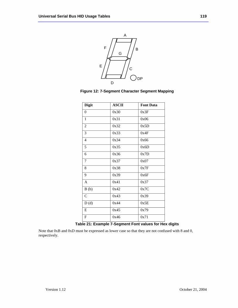
Universal Serial Bus HID Usage Tables 119
Version 1.12 October 21, 2004
Figure 12: 7-Segment Character Segment Mapping
Digit ASCII Font Data
0 0x30 0x3F
1 0x31 0x06
2 0x32 0x5D
3 0x33 0x4F
4 0x34 0x66
5 0x35 0x6D
6 0x36 0x7D
7 0x37 0x07
8 0x38 0x7F
9 0x39 0x6F
A 0x41 0x37
B (b) 0x42 0x7C
C 0x43 0x39
D (d) 0x44 0x5E
E 0x45 0x79
F 0x46 0x71
Table 21: Example 7-Segment Font values for Hex digits
Note that 0xB and 0xD must be expressed as lower case so that they are not confused with 8 and 0, respectively.
DP
A
C
D
BF
E
G
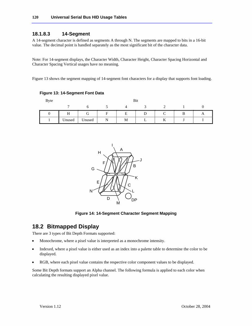
120 Universal Serial Bus HID Usage Tables
Version 1.12 October 28, 2004
18.1.8.3 14-Segment A 14-segment character is defined as segments A through N. The segments are mapped to bits in a 16-bit value. The decimal point is handled separately as the most significant bit of the character data.
Note: For 14-segment displays, the Character Width, Character Height, Character Spacing Horizontal and Character Spacing Vertical usages have no meaning.
Figure 13 shows the segment mapping of 14-segment font characters for a display that supports font loading.
Figure 13: 14-Segment Font Data
Byte Bit 7 6 5 4 3 2 1 0
0 H G F E D C B A 1 Unused Unused N M L K J I
Figure 14: 14-Segment Character Segment Mapping
18.2 Bitmapped Display There are 3 types of Bit Depth Formats supported:
• Monochrome, where a pixel value is interpreted as a monochrome intensity.
• Indexed, where a pixel value is either used as an index into a palette table to determine the color to be displayed.
• RGB, where each pixel value contains the respective color component values to be displayed.
Some Bit Depth formats support an Alpha channel. The following formula is applied to each color when calculating the resulting displayed pixel value.
A
B
C
F
E
D
J
H
K
I
N
M
L
G
DP
Universal Serial Bus HID Usage Tables 121
Version 1.12 October 21, 2004
Displayed Pixel Component = (Blit Data component * Alpha) + (frame buffer data component * (MaximumPossibleAlphaValue - Alpha))
Where a “component” is the R, G, or B value of the an RGB pixel or the brightness value of a monochromatic display. The MaximumPossibleAlphaValue is 1 for a 1 bit Alpha value or 255 for an 8-bit Alpha value.
Bitmapped Display CA - A collection of bitmapped display related usages.
18.2.1 Display Attributes Report The usages defined in this section must be contained in a Display Attributes Report feature report, which declares the basic capabilities of the device.
18.2.1.1 Display Specification Bitmap Size X SV - Specifies the X Resolution -1 of the bitmap segment on the
display.
Bitmap Size Y SV - Specifies the Y Resolution -1 of the bitmap segment on the display.
18.2.1.2 Bit Depth Format Bit Depth Format SV – ID of the bit depth format supported by the device. The format specifies
whether the display is Indexed or RGB, Monochrome or Color, and the bit depth and format of the pixel data. See the Indexed and RGB Formats described below for more details.
Bit Depth Format DV – If multiple Bit Depth formats are supported by a display then multiple Bit Depth Format usages will be declared in a Display Attributes Report. And a Bit Depth usage must be declared in a feature report to allow the client to set the current bit depth format.
18.2.1.2.1 Monochrome and Indexed Formats An Indexed format is specified by ORing it with an RGB BitDepth format value. The resulting value not only specifies the size of the palette table, but the RGB format of its entries. For instance, a BitDepth Format value of 0x13 indicates the palette has 16 entries, where each entry supports a 555 RGB color value.
It is not legal to declare an RGB Format that supports Alpha channels for an Indexed format.
A Palette Report must be declared if an Indexed format is defined. For Indexed formats the system is responsible for initializing all palette entries. For Monochrome formats, a 0 pixel value displays the background color and the maximum pixel value displays the foreground or Active color at maximum intensity.
0x1 - BitDepth Indexed 1 Bit Specifies the display supports a pixel bit depth of 1 bit. If an Indexed format is specified, the palette table will contain 2 entries for specifying two possible colors, where pixel value is the index into the palette table. If a Monochrome format is declared, a 0x0 value displays the Background color for the pixel and a value of 1 displays is the Active color at maximum intensity.
0x2 - BitDepth Indexed 2 Bits Specifies the display supports a bit depth of 2 bits. If an Indexed format is specified, the palette table will contain 4 entries. Not finding a Palette Report indicates a
122 Universal Serial Bus HID Usage Tables
Version 1.12 October 28, 2004
Monochrome format, where a 0x0 value displays the Background color for the pixel and a value of 3 displays is the Active color at maximum intensity.
0x3 - BitDepth Indexed 4 Bits Specifies the display supports a bit depth of 4 bits. If If an Indexed format is specified, the palette table will contain 16 entries. If a Monochrome format is declared, a 0x0 value displays the Background color for the pixel and a value of 0xF displays is the Active color at maximum intensity.
0x4 - BitDepth Indexed 8 Bits Specifies the display supports a bit depth of 8 bits. If an Indexed format is specified, the palette table will contain 256 entries. If a Monochrome format is declared, a 0x0 value displays the Background color for the pixel and a value of 0xFF displays is the Active color at maximum intensity.
18.2.1.2.2 RGB Formats Note that bit 8 of the usage value is asserted if an alpha channel is supported.
0x4 - BitDepth Indexed 8 Bits Specifies the display supports a bit depth of 8 bits. If an Indexed format is specified, the palette table will contain 256 entries. If a Monochrome format is declared, a 0x0 value displays the Background color for the pixel and a value of 0xFF displays is the Active color at maximum intensity.
0x10 - BitDepth RGB 555 Specifies the display supports a bit depth of 15 bits in a 16-bit value. Finding this usage specifies that a Palette Report is invalid. Bits 0-4 indicate the red aspect of a specific pixel. Bits 5-9 indicate the green aspect of the specific pixel. Bits 10-14 indicate the blue aspect of the indexed pixel. Bit 15 is unused in this pixel bit depth.
0x90 - BitDepth ARGB 1555 Specifies the display supports a bit depth of 16 bits. Finding this usage specifies that a Palette Report is invalid. Bits 0-4 indicate the red aspect of a specific pixel. Bits 5-9 indicate the green aspect of the specific pixel. Bits 10-14 indicate the blue aspect of the indexed pixel. Bit 15 is the alpha value of the pixel.
0x20 - BitDepth RGB 565 Specifies the display supports a bit depth of 16 bits. Finding this usage specifies that a Palette Report is invalid. Bits 0-4 indicate the red aspect of a specific pixel. Bits 5-10 indicate the green aspect of the specific pixel. Bits 11-15 indicate the blue aspect of the indexed pixel.
0x30 - BitDepth RGB 888 Specifies the display supports a bit depth of 24 bits. Finding this usage specifies that a Palette Report is invalid. Bits 0-7 indicate the red aspect of a specific pixel. Bits 8-15 indicate the green aspect of the specific pixel. Bits 16-23 indicate the blue aspect of the indexed pixel.
0xC0 - BitDepth ARGB 8888 Specifies the display supports a bit depth of 32 bits. Finding this usage specifies that a Palette Report is invalid. Bits 0-7 indicate the red aspect of a specific pixel. Bits 8-15 indicate the green aspect of the specific pixel. Bits 16-24 indicate the blue aspect of the indexed pixel. Bits 25-31 indicate the alpha value of the pixel.
0xA - BitDepth PARGB 8888 Specifies the display supports a bit depth of 32 bits. Finding this usage specifies that a Palette Report is invalid. The first 8 bit is the alpha value of the pixel. Note that the
Universal Serial Bus HID Usage Tables 123
Version 1.12 October 21, 2004
alpha value should be calculated into the following 24 bits of the pixel data. The second 8 bits indicate the red aspect of a specific pixel. The third 8 bits indicate the green aspect of the specific pixel. The fourth 8 bits indicate the blue aspect of the indexed pixel.
0x40 - BitDepth 8880 Specifies the display supports a bit depth of 32 bits. Finding this usage specifies that a Palette Report is invalid. Bits 0-7 indicate the red aspect of a specific pixel. Bits 8-15 indicate the green aspect of the specific pixel. Bits 16-23 indicate the blue aspect of the indexed pixel. Bits 24-31 of the pixel data should be set to 0 and are ignored by the display.
18.2.1.3 Soft Buttons Soft (unlabeled) Buttons can be positioned around the edges of the display. Knowing the position of the button, an application can render text or an icon close to the button that has the associated function, defining its purpose.
The existence of a Soft Button collection in a Report descriptor indicates that the device supports Soft Buttons. A Soft Button collection defines the position of soft button. This information is normally retrieved at initialization time. During run time, input reports are generated to indicate changes in the state of a button.
Note: The button collection will include usages from the functional Button Usage Page (0x09) in order to represent hardware buttons with an associated function.
Soft Button CL – This usage encapsulates 4 usages that define a Soft Button. The usages are; a Button Usage Page declaration that defines button number, and Soft Button Offset 1, Soft Button Offset 2, and Soft Button Side that defined the position of the button on the periphery of the display. A Soft Button collection is declared for each soft button present on the display.
Soft Button ID SV – Specifies the Y Resolution -1 of the bitmap segment on the display.
Soft Button Side SV – This usage specifies the side of the display where the button resides. Where, 0 = top, 1 = bottom, 2 = left side. 3 = right side.
Soft Button Offset 1 SV – A static value that specifies the offset in pixels of the top or left edge of the button. If the Soft Button Side usage equals top or bottom then the offset is in the column position of the side of the button nearest the origin. If the Soft Button Side usage equals right or left then the offset is in the row position of the side of the button nearest the origin.
Soft Button Offset 2 SV – A static value that specifies the offset in pixels of the bottom or right edge of the button. If the Soft Button Side usage equals top or bottom then the offset is in the column position of the side of the button farthest from the origin. If the Soft Button Side usage equals right or left then the offset is in the row position of the side of the button farthest from the origin.
18.2.2 Orientation Pixels are addressed in row and columns. The origin or 0,0 position is always in the upper left hand corner of the display. Below is an example of a 128x64 bitmapped display.
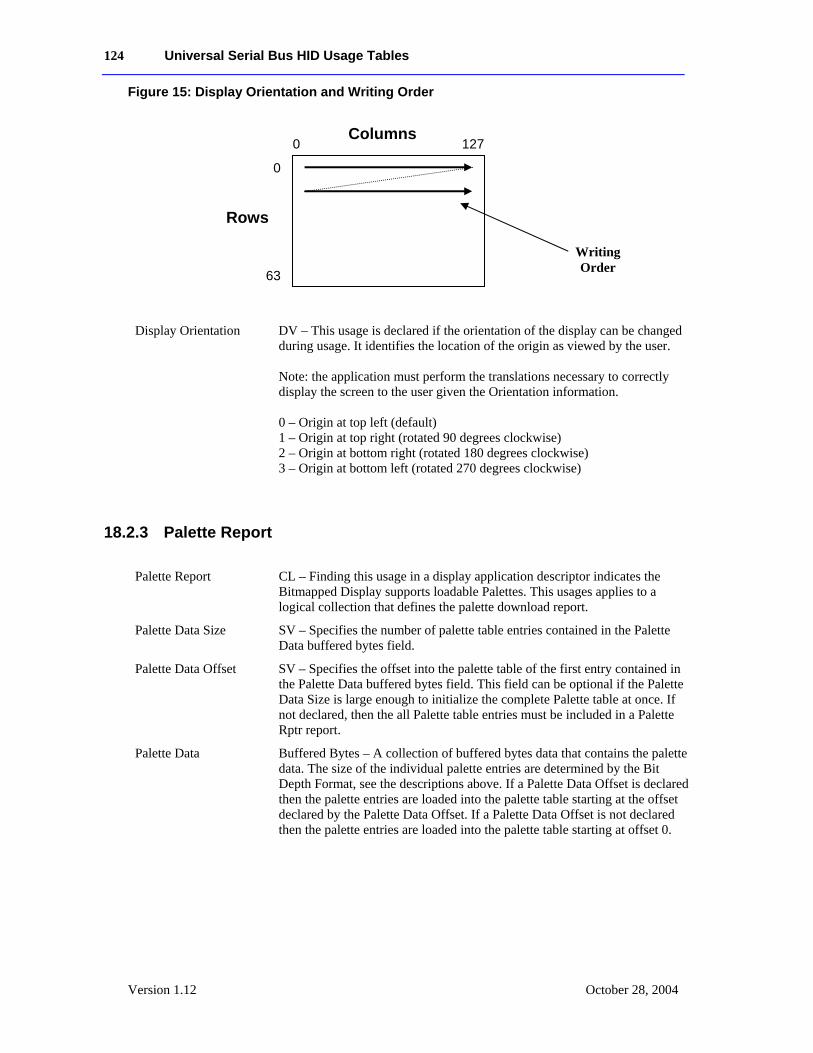
124 Universal Serial Bus HID Usage Tables
Version 1.12 October 28, 2004
Figure 15: Display Orientation and Writing Order
Display Orientation DV – This usage is declared if the orientation of the display can be changed during usage. It identifies the location of the origin as viewed by the user. Note: the application must perform the translations necessary to correctly display the screen to the user given the Orientation information. 0 – Origin at top left (default) 1 – Origin at top right (rotated 90 degrees clockwise) 2 – Origin at bottom right (rotated 180 degrees clockwise) 3 – Origin at bottom left (rotated 270 degrees clockwise)
18.2.3 Palette Report
Palette Report CL – Finding this usage in a display application descriptor indicates the Bitmapped Display supports loadable Palettes. This usages applies to a logical collection that defines the palette download report.
Palette Data Size SV – Specifies the number of palette table entries contained in the Palette Data buffered bytes field.
Palette Data Offset SV – Specifies the offset into the palette table of the first entry contained in the Palette Data buffered bytes field. This field can be optional if the Palette Data Size is large enough to initialize the complete Palette table at once. If not declared, then the all Palette table entries must be included in a Palette Rptr report.
Palette Data Buffered Bytes – A collection of buffered bytes data that contains the palette data. The size of the individual palette entries are determined by the Bit Depth Format, see the descriptions above. If a Palette Data Offset is declared then the palette entries are loaded into the palette table starting at the offset declared by the Palette Data Offset. If a Palette Data Offset is not declared then the palette entries are loaded into the palette table starting at offset 0.
0 127
0
63
Columns
Rows
Writing Order
Universal Serial Bus HID Usage Tables 125
Version 1.12 October 21, 2004
18.2.4 Blit Report
Blit Report CL – This usage is required for moving data to or from a Bitmapped Display Device.
The maximum size of a blit (in bytes) that is supported by the display, is defined by the size of the buffered bytes field in the Blit Report.
The following Blit Rectangle coordinates specify the bounding rectangle X1, Y1, X2, Y2 where the Blit Data buffer will be moved. The coordinate values assume the default Orientation of the display. See section 1.1.2 for more information on the default orientation.
If no Blit Rectangle usages are declared, then the client should assume that the data provided in the Blit Data is for the entire display buffer. i.e. the blit rectangle is (0,0, Bitmap Size X – 1, Bitmap Size Y – 1).
If a coordinate of the bounding rectangle is outside the boundaries of the display, the display will ignore data for this part of the Blit Data Buffer.
Blit Rectangle X1 DV – Specifies the X component of the top left corner of the rectangle for the blit.
Blit Rectangle Y1 DV – Specifies the Y component of the top left corner of the rectangle for the blit.
Blit Rectangle X2 DV – Specifies the X component of the bottom right corner of the rectangle for the blit.
Blit Rectangle Y2 DV – Specifies the Y component of the bottom right corner of the rectangle for the blit.
Blit Data Buffered Bytes – The buffer that contains the pixel data for each pixel in a blit to a display. The number of pixels contained in the Blit Data buffer equals: (Blit Rectangle X1 - Blit Rectangle X2) * (Blit Rectangle Y1 - Blit Rectangle Y2). The format of the pixel data is a function of the Bit Depth Format, see section 18.2.1.
18.2.5 Soft Button Report
Soft Button Report The Soft Button Report collection will include usages from the Button Usage page (0x09), which provides usages for generic non-function based button usages. The IDs of these buttons are defined in a Soft Button collection.
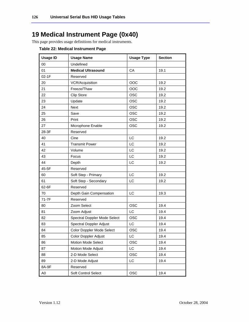
126 Universal Serial Bus HID Usage Tables
Version 1.12 October 28, 2004
19 Medical Instrument Page (0x40) This page provides usage definitions for medical instruments.
Table 22: Medical Instrument Page
Usage ID Usage Name Usage Type Section
00 Undefined
01 Medical Ultrasound CA 19.1
02-1F Reserved
20 VCR/Acquisition OOC 19.2
21 Freeze/Thaw OOC 19.2
22 Clip Store OSC 19.2
23 Update OSC 19.2
24 Next OSC 19.2
25 Save OSC 19.2
26 Print OSC 19.2
27 Microphone Enable OSC 19.2
28-3F Reserved
40 Cine LC 19.2
41 Transmit Power LC 19.2
42 Volume LC 19.2
43 Focus LC 19.2
44 Depth LC 19.2
45-5F Reserved
60 Soft Step - Primary LC 19.2
61 Soft Step - Secondary LC 19.2
62-6F Reserved
70 Depth Gain Compensation LC 19.3
71-7F Reserved
80 Zoom Select OSC 19.4
81 Zoom Adjust LC 19.4
82 Spectral Doppler Mode Select OSC 19.4
83 Spectral Doppler Adjust LC 19.4
84 Color Doppler Mode Select OSC 19.4
85 Color Doppler Adjust LC 19.4
86 Motion Mode Select OSC 19.4
87 Motion Mode Adjust LC 19.4
88 2-D Mode Select OSC 19.4
89 2-D Mode Adjust LC 19.4
8A-9F Reserved
A0 Soft Control Select OSC 19.4
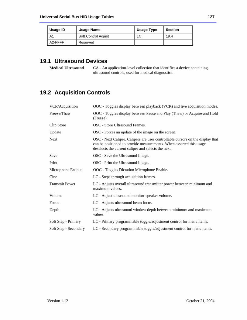
Universal Serial Bus HID Usage Tables 127
Version 1.12 October 21, 2004
Usage ID Usage Name Usage Type Section
A1 Soft Control Adjust LC 19.4
A2-FFFF Reserved
19.1 Ultrasound Devices Medical Ultrasound CA - An application-level collection that identifies a device containing
ultrasound controls, used for medical diagnostics.
19.2 Acquisition Controls
VCR/Acquisition OOC - Toggles display between playback (VCR) and live acquisition modes.
Freeze/Thaw OOC - Toggles display between Pause and Play (Thaw) or Acquire and Hold (Freeze).
Clip Store OSC - Store Ultrasound Frames.
Update OSC - Forces an update of the image on the screen.
Next OSC - Next Caliper. Calipers are user controllable cursors on the display that can be positioned to provide measurements. When asserted this usage deselects the current caliper and selects the next.
Save OSC - Save the Ultrasound Image.
Print OSC - Print the Ultrasound Image.
Microphone Enable OOC - Toggles Dictation Microphone Enable.
Cine LC - Steps through acquisition frames.
Transmit Power LC - Adjusts overall ultrasound transmitter power between minimum and maximum values.
Volume LC - Adjust ultrasound monitor-speaker volume.
Focus LC - Adjusts ultrasound beam focus.
Depth LC - Adjusts ultrasound window depth between minimum and maximum values.
Soft Step - Primary LC - Primary programmable toggle/adjustment control for menu items.
Soft Step - Secondary LC - Secondary programmable toggle/adjustment control for menu items.
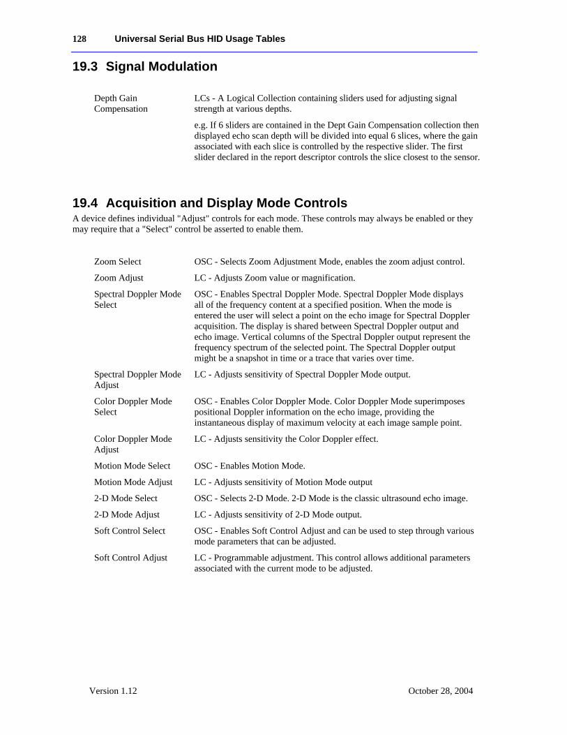
128 Universal Serial Bus HID Usage Tables
Version 1.12 October 28, 2004
19.3 Signal Modulation
Depth Gain Compensation
LCs - A Logical Collection containing sliders used for adjusting signal strength at various depths.
e.g. If 6 sliders are contained in the Dept Gain Compensation collection then displayed echo scan depth will be divided into equal 6 slices, where the gain associated with each slice is controlled by the respective slider. The first slider declared in the report descriptor controls the slice closest to the sensor.
19.4 Acquisition and Display Mode Controls A device defines individual "Adjust" controls for each mode. These controls may always be enabled or they may require that a "Select" control be asserted to enable them.
Zoom Select OSC - Selects Zoom Adjustment Mode, enables the zoom adjust control.
Zoom Adjust LC - Adjusts Zoom value or magnification.
Spectral Doppler Mode Select
OSC - Enables Spectral Doppler Mode. Spectral Doppler Mode displays all of the frequency content at a specified position. When the mode is entered the user will select a point on the echo image for Spectral Doppler acquisition. The display is shared between Spectral Doppler output and echo image. Vertical columns of the Spectral Doppler output represent the frequency spectrum of the selected point. The Spectral Doppler output might be a snapshot in time or a trace that varies over time.
Spectral Doppler Mode Adjust
LC - Adjusts sensitivity of Spectral Doppler Mode output.
Color Doppler Mode Select
OSC - Enables Color Doppler Mode. Color Doppler Mode superimposes positional Doppler information on the echo image, providing the instantaneous display of maximum velocity at each image sample point.
Color Doppler Mode Adjust
LC - Adjusts sensitivity the Color Doppler effect.
Motion Mode Select OSC - Enables Motion Mode.
Motion Mode Adjust LC - Adjusts sensitivity of Motion Mode output
2-D Mode Select OSC - Selects 2-D Mode. 2-D Mode is the classic ultrasound echo image.
2-D Mode Adjust LC - Adjusts sensitivity of 2-D Mode output.
Soft Control Select OSC - Enables Soft Control Adjust and can be used to step through various mode parameters that can be adjusted.
Soft Control Adjust LC - Programmable adjustment. This control allows additional parameters associated with the current mode to be adjusted.

Universal Serial Bus HID Usage Tables 129
Version 1.12 October 21, 2004
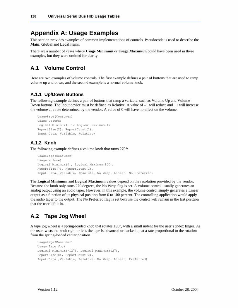
130 Universal Serial Bus HID Usage Tables
Version 1.12 October 28, 2004
Appendix A: Usage Examples This section provides examples of common implementations of controls. Pseudocode is used to describe the Main, Global and Local items.
There are a number of cases where Usage Minimum or Usage Maximum could have been used in these examples, but they were omitted for clarity.
A.1 Volume Control Here are two examples of volume controls. The first example defines a pair of buttons that are used to ramp volume up and down, and the second example is a normal volume knob.
A.1.1 Up/Down Buttons The following example defines a pair of buttons that ramp a variable, such as Volume Up and Volume Down buttons. The Input device must be defined as Relative. A value of –1 will reduce and +1 will increase the volume at a rate determined by the vendor. A value of 0 will have no effect on the volume.
UsagePage(Consumer) Usage(Volume) Logical Minimum(-1), Logical Maximum(1), ReportSize(2), ReportCount(1), Input(Data, Variable, Relative)
A.1.2 Knob The following example defines a volume knob that turns 270°:
UsagePage(Consumer) Usage(Volume) Logical Minimum(0), Logical Maximum(100), ReportSize(7), ReportCount(1), Input(Data, Variable, Absolute, No Wrap, Linear, No Preferred)
The Logical Minimum and Logical Maximum values depend on the resolution provided by the vendor. Because the knob only turns 270 degrees, the No Wrap flag is set. A volume control usually generates an analog output using an audio taper. However, in this example, the volume control simply generates a Linear output as a function of its physical position from 0 to 100 percent. The controlling application would apply the audio taper to the output. The No Preferred flag is set because the control will remain in the last position that the user left it in.
A.2 Tape Jog Wheel A tape jog wheel is a spring-loaded knob that rotates ±90°, with a small indent for the user’s index finger. As the user twists the knob right or left, the tape is advanced or backed up at a rate proportional to the rotation from the spring-loaded center position.
UsagePage(Consumer) Usage(Tape Jog) Logical Minimum(-127), Logical Maximum(127), ReportSize(8), ReportCount(2), Input(Data ,Variable, Relative, No Wrap, Linear, Preferred)
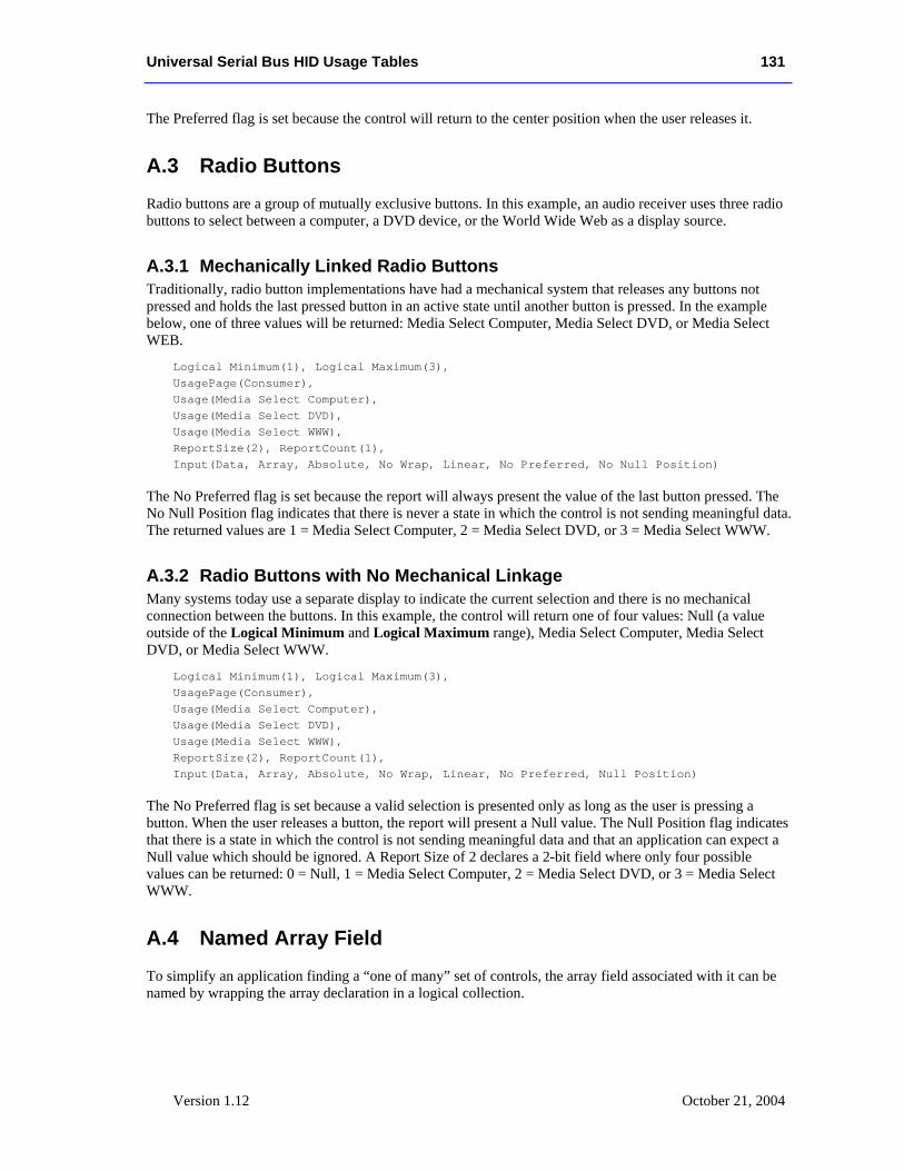
Universal Serial Bus HID Usage Tables 131
Version 1.12 October 21, 2004
The Preferred flag is set because the control will return to the center position when the user releases it.
A.3 Radio Buttons Radio buttons are a group of mutually exclusive buttons. In this example, an audio receiver uses three radio buttons to select between a computer, a DVD device, or the World Wide Web as a display source.
A.3.1 Mechanically Linked Radio Buttons Traditionally, radio button implementations have had a mechanical system that releases any buttons not pressed and holds the last pressed button in an active state until another button is pressed. In the example below, one of three values will be returned: Media Select Computer, Media Select DVD, or Media Select WEB.
Logical Minimum(1), Logical Maximum(3), UsagePage(Consumer), Usage(Media Select Computer), Usage(Media Select DVD), Usage(Media Select WWW), ReportSize(2), ReportCount(1), Input(Data, Array, Absolute, No Wrap, Linear, No Preferred, No Null Position)
The No Preferred flag is set because the report will always present the value of the last button pressed. The No Null Position flag indicates that there is never a state in which the control is not sending meaningful data. The returned values are 1 = Media Select Computer, 2 = Media Select DVD, or 3 = Media Select WWW.
A.3.2 Radio Buttons with No Mechanical Linkage Many systems today use a separate display to indicate the current selection and there is no mechanical connection between the buttons. In this example, the control will return one of four values: Null (a value outside of the Logical Minimum and Logical Maximum range), Media Select Computer, Media Select DVD, or Media Select WWW.
Logical Minimum(1), Logical Maximum(3), UsagePage(Consumer), Usage(Media Select Computer), Usage(Media Select DVD), Usage(Media Select WWW), ReportSize(2), ReportCount(1), Input(Data, Array, Absolute, No Wrap, Linear, No Preferred, Null Position)
The No Preferred flag is set because a valid selection is presented only as long as the user is pressing a button. When the user releases a button, the report will present a Null value. The Null Position flag indicates that there is a state in which the control is not sending meaningful data and that an application can expect a Null value which should be ignored. A Report Size of 2 declares a 2-bit field where only four possible values can be returned: 0 = Null, 1 = Media Select Computer, 2 = Media Select DVD, or 3 = Media Select WWW.
A.4 Named Array Field To simplify an application finding a “one of many” set of controls, the array field associated with it can be named by wrapping the array declaration in a logical collection.
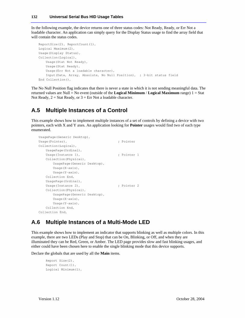
132 Universal Serial Bus HID Usage Tables
Version 1.12 October 28, 2004
In the following example, the device returns one of three status codes: Not Ready, Ready, or Err Not a loadable character. An application can simply query for the Display Status usage to find the array field that will contain the status codes.
ReportSize(2), ReportCount(1), Logical Maximum(2), Usage(Display Status), Collection(Logical), Usage(Stat Not Ready), Usage(Stat Ready), Usage(Err Not a loadable character), Input(Data, Array, Absolute, No Null Position), ; 3-bit status field End Collection(),
The No Null Position flag indicates that there is never a state in which it is not sending meaningful data. The returned values are Null = No event (outside of the Logical Minimum / Logical Maximum range) 1 = Stat Not Ready, 2 = Stat Ready, or 3 = Err Not a loadable character.
A.5 Multiple Instances of a Control This example shows how to implement multiple instances of a set of controls by defining a device with two pointers, each with X and Y axes. An application looking for Pointer usages would find two of each type enumerated.
UsagePage(Generic Desktop), Usage(Pointer), ; Pointer Collection(Logical), UsagePage(Ordinal), Usage(Instance 1), ; Pointer 1 Collection(Physical), UsagePage(Generic Desktop), Usage(X-axis), Usage(Y-axis), Collection End, UsagePage(Ordinal), Usage(Instance 2), ; Pointer 2 Collection(Physical), UsagePage(Generic Desktop), Usage(X-axis), Usage(Y-axis), Collection End, Collection End,
A.6 Multiple Instances of a Multi-Mode LED
This example shows how to implement an indicator that supports blinking as well as multiple colors. In this example, there are two LEDs (Play and Stop) that can be On, Blinking, or Off, and when they are illuminated they can be Red, Green, or Amber. The LED page provides slow and fast blinking usages, and either could have been chosen here to enable the single blinking mode that this device supports. Declare the globals that are used by all the Main items.
Report Size(2), Report Count(1), Logical Minimum(1),
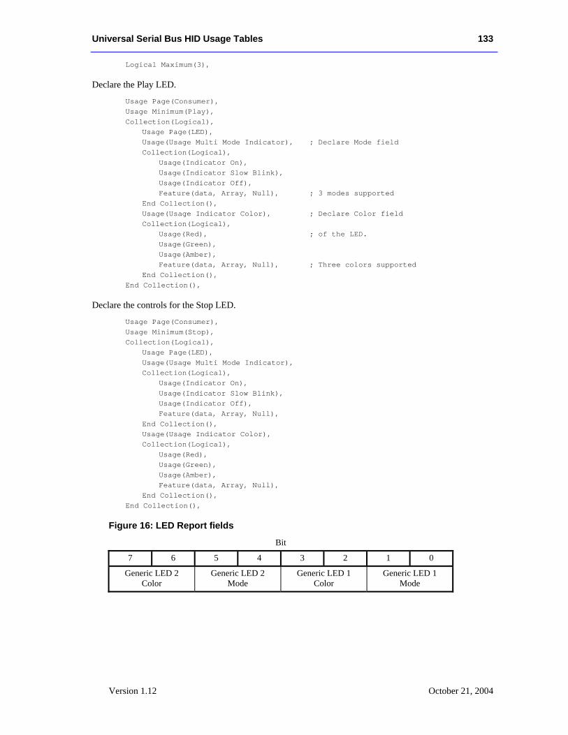
Universal Serial Bus HID Usage Tables 133
Version 1.12 October 21, 2004
Logical Maximum(3),
Declare the Play LED.
Usage Page(Consumer), Usage Minimum(Play), Collection(Logical), Usage Page(LED), Usage(Usage Multi Mode Indicator), ; Declare Mode field Collection(Logical), Usage(Indicator On), Usage(Indicator Slow Blink), Usage(Indicator Off), Feature(data, Array, Null), ; 3 modes supported End Collection(), Usage(Usage Indicator Color), ; Declare Color field Collection(Logical), Usage(Red), ; of the LED. Usage(Green), Usage(Amber), Feature(data, Array, Null), ; Three colors supported End Collection(), End Collection(),
Declare the controls for the Stop LED.
Usage Page(Consumer), Usage Minimum(Stop), Collection(Logical), Usage Page(LED), Usage(Usage Multi Mode Indicator), Collection(Logical), Usage(Indicator On), Usage(Indicator Slow Blink), Usage(Indicator Off), Feature(data, Array, Null), End Collection(), Usage(Usage Indicator Color), Collection(Logical), Usage(Red), Usage(Green), Usage(Amber), Feature(data, Array, Null), End Collection(), End Collection(), Figure 16: LED Report fields
Bit
7 6 5 4 3 2 1 0
Generic LED 2 Color
Generic LED 2 Mode
Generic LED 1 Color
Generic LED 1 Mode
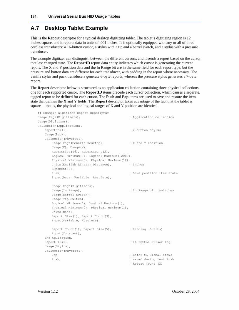
134 Universal Serial Bus HID Usage Tables
Version 1.12 October 28, 2004
A.7 Desktop Tablet Example This is the Report descriptor for a typical desktop digitizing tablet. The tablet’s digitizing region is 12 inches square, and it reports data in units of .001 inches. It is optionally equipped with any or all of three cordless transducers: a 16-button cursor, a stylus with a tip and a barrel switch, and a stylus with a pressure transducer.
The example digitizer can distinguish between the different cursors, and it sends a report based on the cursor that last changed state. The ReportID report data entity indicates which cursor is generating the current report. The X and Y position data and the In Range bit are in the same field for each report type, but the pressure and button data are different for each transducer, with padding in the report where necessary. The vanilla stylus and puck transducers generate 6-byte reports, whereas the pressure stylus generates a 7-byte report.
The Report descriptor below is structured as an application collection containing three physical collections, one for each supported cursor. The ReportID items precede each cursor collection, which causes a separate, tagged report to be defined for each cursor. The Push and Pop items are used to save and restore the item state that defines the X and Y fields. The Report descriptor takes advantage of the fact that the tablet is square— that is, the physical and logical ranges of X and Y position are identical.
;; Example Digitizer Report Descriptor Usage Page(Digitizers), ; Application collection Usage(Digitizer), Collection(Application), ReportID(1), ; 2-Button Stylus Usage(Puck), Collection(Physical), Usage Page(Generic Desktop), ; X and Y Position Usage(X), Usage(Y), ReportSize(16), ReportCount(2), Logical Minimum(0), Logical Maximum(12000), Physical Minimum(0), Physical Maximum(12), Units(English Linear: Distance), ; Inches Exponent(0), Push, ; Save position item state Input(Data, Variable, Absolute), Usage Page(Digitizers), Usage(In Range), ; In Range bit, switches Usage(Barrel Switch), Usage(Tip Switch), Logical Minimum(0), Logical Maximum(1), Physical Minimum(0), Physical Maximum(1), Units(None), Report Size(1), Report Count(3), Input(Variable, Absolute), Report Count(1), Report Size(5), ; Padding (5 bits) Input(Constant), End Collection, Report ID(2), ; 16-Button Cursor Tag Usage(Stylus), Collection(Physical), Pop, ; Refer to Global items Push, ; saved during last Push ; Report Count (2)
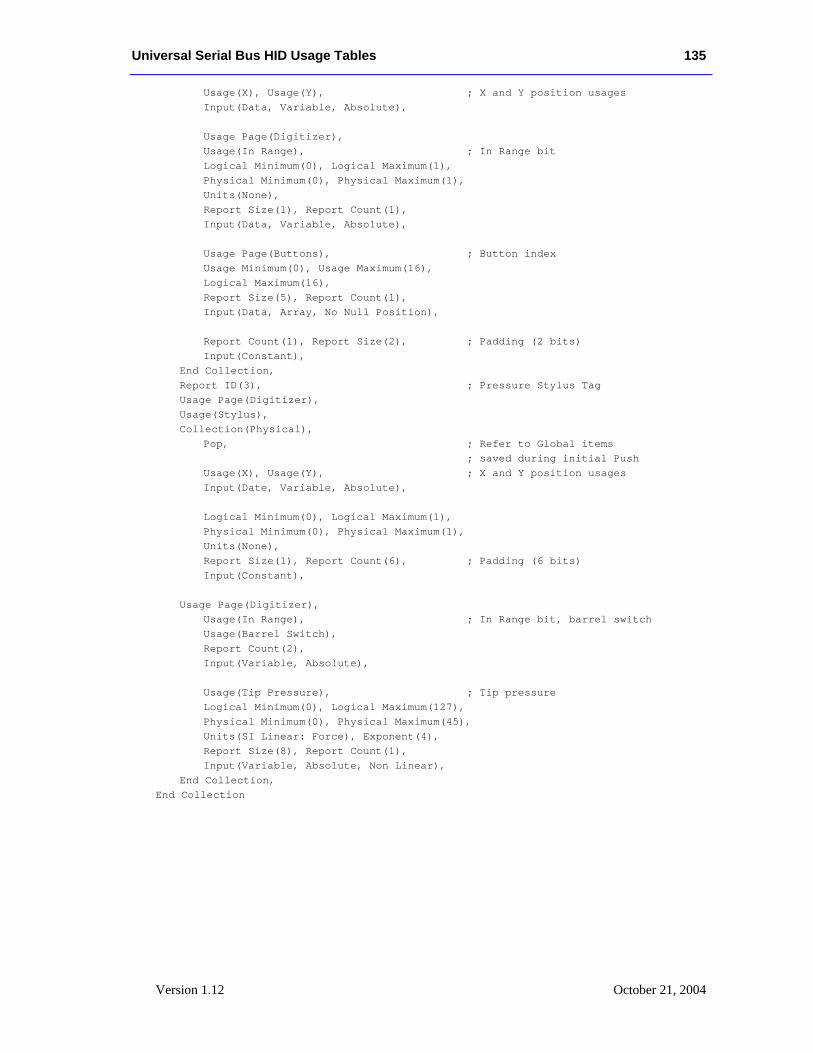
Universal Serial Bus HID Usage Tables 135
Version 1.12 October 21, 2004
Usage(X), Usage(Y), ; X and Y position usages Input(Data, Variable, Absolute), Usage Page(Digitizer), Usage(In Range), ; In Range bit Logical Minimum(0), Logical Maximum(1), Physical Minimum(0), Physical Maximum(1), Units(None), Report Size(1), Report Count(1), Input(Data, Variable, Absolute), Usage Page(Buttons), ; Button index Usage Minimum(0), Usage Maximum(16), Logical Maximum(16), Report Size(5), Report Count(1), Input(Data, Array, No Null Position), Report Count(1), Report Size(2), ; Padding (2 bits) Input(Constant), End Collection, Report ID(3), ; Pressure Stylus Tag Usage Page(Digitizer), Usage(Stylus), Collection(Physical), Pop, ; Refer to Global items ; saved during initial Push Usage(X), Usage(Y), ; X and Y position usages Input(Date, Variable, Absolute), Logical Minimum(0), Logical Maximum(1), Physical Minimum(0), Physical Maximum(1), Units(None), Report Size(1), Report Count(6), ; Padding (6 bits) Input(Constant), Usage Page(Digitizer), Usage(In Range), ; In Range bit, barrel switch Usage(Barrel Switch), Report Count(2), Input(Variable, Absolute), Usage(Tip Pressure), ; Tip pressure Logical Minimum(0), Logical Maximum(127), Physical Minimum(0), Physical Maximum(45), Units(SI Linear: Force), Exponent(4), Report Size(8), Report Count(1), Input(Variable, Absolute, Non Linear), End Collection, End Collection
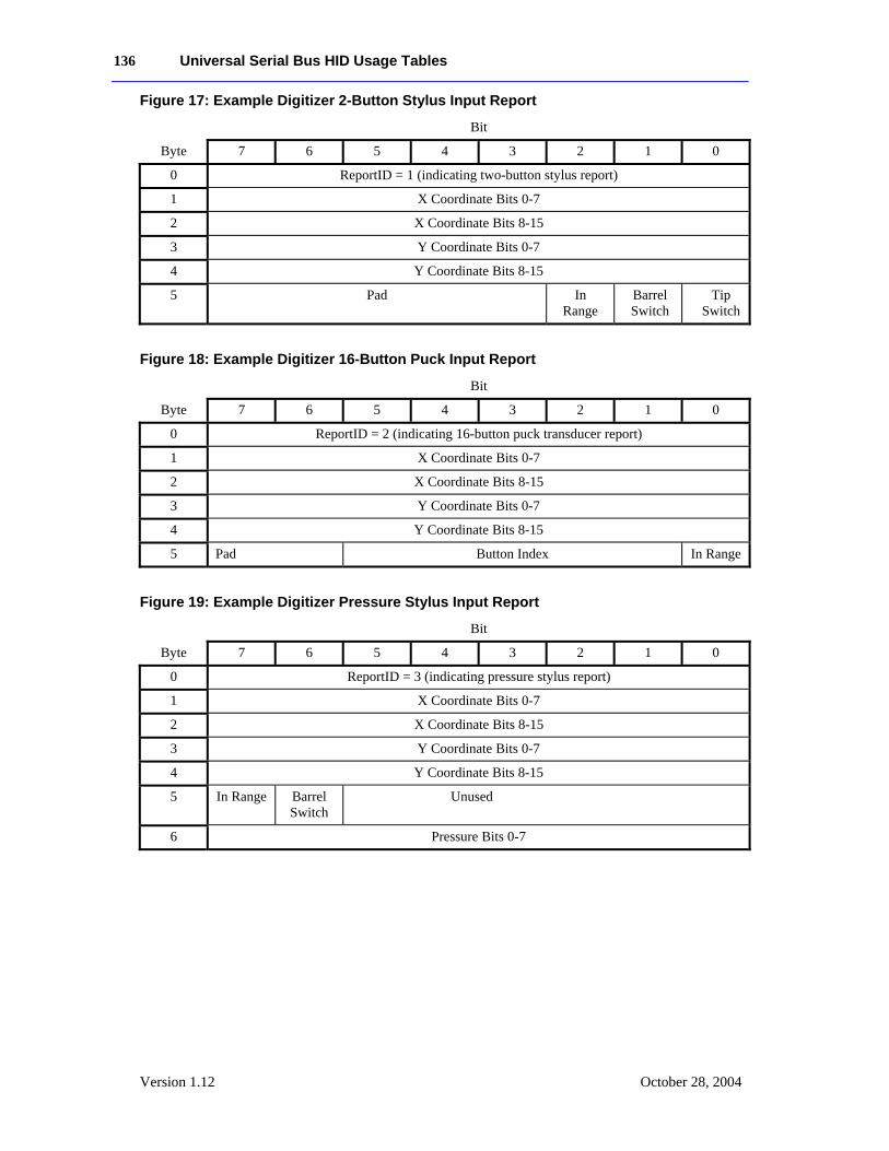
136 Universal Serial Bus HID Usage Tables
Version 1.12 October 28, 2004
Figure 17: Example Digitizer 2-Button Stylus Input Report
Bit
Byte 7 6 5 4 3 2 1 0
0 ReportID = 1 (indicating two-button stylus report)
1 X Coordinate Bits 0-7
2 X Coordinate Bits 8-15
3 Y Coordinate Bits 0-7
4 Y Coordinate Bits 8-15
5 Pad In Range
Barrel Switch
Tip Switch
Figure 18: Example Digitizer 16-Button Puck Input Report
Bit
Byte 7 6 5 4 3 2 1 0
0 ReportID = 2 (indicating 16-button puck transducer report)
1 X Coordinate Bits 0-7
2 X Coordinate Bits 8-15
3 Y Coordinate Bits 0-7
4 Y Coordinate Bits 8-15
5 Pad Button Index In Range
Figure 19: Example Digitizer Pressure Stylus Input Report
Bit
Byte 7 6 5 4 3 2 1 0
0 ReportID = 3 (indicating pressure stylus report)
1 X Coordinate Bits 0-7
2 X Coordinate Bits 8-15
3 Y Coordinate Bits 0-7
4 Y Coordinate Bits 8-15
5 In Range Barrel Switch
Unused
6 Pressure Bits 0-7
Universal Serial Bus HID Usage Tables 137
Version 1.12 October 21, 2004
A.8 A Device with a Display The following example is of a 2x16-character display device. The device uses one Feature, one Input, and two Output reports.
A Feature report is declared for identifying fixed features of the display and display status. All of the Feature report’s fields are constants.
The Character Spacing usage is not declared, so it can be assumed that the respective inter-character spacing is forced by the pixel layout of the display, and any downloaded font characters do not have to include it.
In this example, the Character Height and Width are fixed. The fields are declared in the Report descriptor and the actual values are reported when the Feature report is read. For example, the Character Height and Width fields will always return 7 and 5, respectively.
Uploading of the font is not supported by this display so there is no Font Report Input report.
UsagePage(Alphanumeric Display), Usage(Alphanumeric Display), Logical Minimum(0), Collection(Application),
The first report defined is a Feature report with seven fields. The Rows, Columns, Character Height and Width fields are Static Values (SV) and their report size is set to 5 to demonstrate how the bit packing takes place in a report. Standard Character Set, Data Read Back and Vertical Scroll are Static Flags (SF).
Usage(Display Attributes Report), Collection(Logical), Usage(Rows), ; Constant = 2 Usage(Columns), ; Constant = 16 Usage(Character Width), ; Constant = 5 Usage(Character Height), ; Constant = 7 ReportID(1), Logical Maximum(31), ReportSize(5), ReportCount(4), Feature(Constant, Variable, Absolute), ; Four 5-bit fields ReportSize(1), ReportCount(3), Logical Maximum(1), Usage(ASCII Character Set), ; Constant = 1 Usage(Data Read Back), ; Constant = 1 Usage(Vertical Scroll), ; Constant = 1 Feature(Constant, Variable, Absolute), ; Three 1-bit fields ReportCount(1), Feature(Constant, Variable, Absolute), ; 1-bit pad
The following Character Attributes collection defines a byte where bits 0, 1, and 2 define Enhance, Underline, and Blink attributes that can be applied to a character. The remaining bits in the byte pad it to a byte boundary and ignored by the display. Modifying the fields defined in this collection will have no effect on the display. They simply form a template that is used to define the contents of a Attribute Data report.
Usage (Character Attributes) Collection(Logical) Usage(Char Attr Enhance) Usage(Char Attr Underline Usage(Char Attr Blink)
138 Universal Serial Bus HID Usage Tables
Version 1.12 October 28, 2004
ReportSize(1) ReportCount(3) Feature(Const, var) ReportSize(5) ReportCount(1) Feature(Const) // pad to byte boundary End Collection() End Collection(),
The second report defined is an Input report that is generated on the interrupt endpoint each time the status of the display changes. Each of the possible states that can be identified by the display are identified in the Display Status collection. This report can also be read over the control pipe to determine the current status.
ReportSize(8), ReportCount(1), Logical Maximum(2), Usage(Display Status), Collection(Logical), Usage(Stat Not Ready), Usage(Stat Ready), Usage(Err Not a loadable character), Input(Data, Array, Absolute, No Null), ; 8-bit status field End Collection(),
A second Feature report is defined for getting or setting the current cursor position.
Usage(Cursor Position Report), Collection(Logical), ReportID(2), ReportSize(4), ReportCount(1), Logical Maximum(15), Usage(Column), Feature(Data, Variable, Absolute, No Preferred State), ;Column Logical Maximum(1), Usage(Row), Feature(Data, Variable, Absolute, No Preferred State), ;Row End Collection(),
There are a number of ways that data can be transferred between the host and the display: one byte at a time, multiple bytes, or the whole screen using a 32-byte buffered-byte transfer. The choice may depend on whether the device is implemented as a low-speed or a high-speed device. In this example, a third Feature report is defined for writing up to four sequential characters from the display in a single report. Note that the Data Read Back usage is not declared in the Report descriptor, which implies that the display character data is write-only
The following Character Report contains 2, 4 byte fields, one for character data and another for character attributes. Each allow 4 characters to be modified simultaneously.
Usage (Character Report) Collection(Logical) ReportID (3) Usage (Display Data) ReportSize(8) ReportCount(4) Feature(Data, Variable, Absolute, Buffered Bytes), ;4-byte data buffer
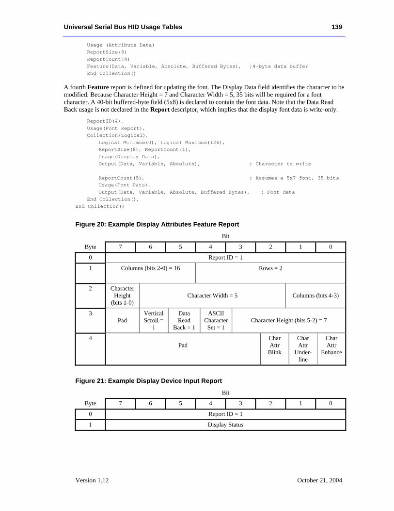
Universal Serial Bus HID Usage Tables 139
Version 1.12 October 21, 2004
Usage (Attribute Data) ReportSize(8) ReportCount(4) Feature(Data, Variable, Absolute, Buffered Bytes), ;4-byte data buffer End Collection()
A fourth Feature report is defined for updating the font. The Display Data field identifies the character to be modified. Because Character Height = 7 and Character Width = 5, 35 bits will be required for a font character. A 40-bit buffered-byte field (5x8) is declared to contain the font data. Note that the Data Read Back usage is not declared in the Report descriptor, which implies that the display font data is write-only.
ReportID(4), Usage(Font Report), Collection(Logical), Logical Minimum(0), Logical Maximum(126), ReportSize(8), ReportCount(1), Usage(Display Data), Output(Data, Variable, Absolute), ; Character to write ReportCount(5), ; Assumes a 5x7 font, 35 bits Usage(Font Data), Output(Data, Variable, Absolute, Buffered Bytes), ; Font data End Collection(), End Collection()
Figure 20: Example Display Attributes Feature Report
Bit
Byte 7 6 5 4 3 2 1 0
0 Report ID = 1
1 Columns (bits 2-0) = 16
Rows = 2
2 Character Height
(bits 1-0)
Character Width = 5
Columns (bits 4-3)
3 Pad
Vertical Scroll =
1
Data Read
Back = 1
ASCII Character
Set = 1
Character Height (bits 5-2) = 7
4 Pad
Char Attr
Blink
Char Attr
Under-line
Char Attr
Enhance
Figure 21: Example Display Device Input Report
Bit
Byte 7 6 5 4 3 2 1 0
0 Report ID = 1
1 Display Status
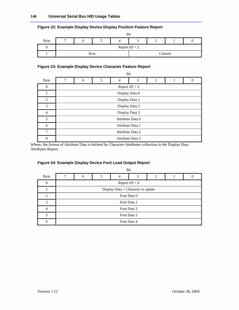
140 Universal Serial Bus HID Usage Tables
Version 1.12 October 28, 2004
Figure 22: Example Display Device Display Position Feature Report
Bit
Byte 7 6 5 4 3 2 1 0
0 Report ID = 2
1 Row Column
Figure 23: Example Display Device Character Feature Report
Bit
Byte 7 6 5 4 3 2 1 0
0 Report ID = 3
1 Display Data 0
2 Display Data 1
3 Display Data 2
4 Display Data 3
5 Attribute Data 0
6 Attribute Data 1
7 Attribute Data 2
8 Attribute Data 3
Where, the format of Attribute Data is defined by Character Attributes collection in the Display Data Attributes Report.
Figure 24: Example Display Device Font Load Output Report
Bit
Byte 7 6 5 4 3 2 1 0
0 Report ID = 4
1 Display Data = Character to update
2 Font Data 0
3 Font Data 1
4 Font Data 2
5 Font Data 3
6 Font Data 4
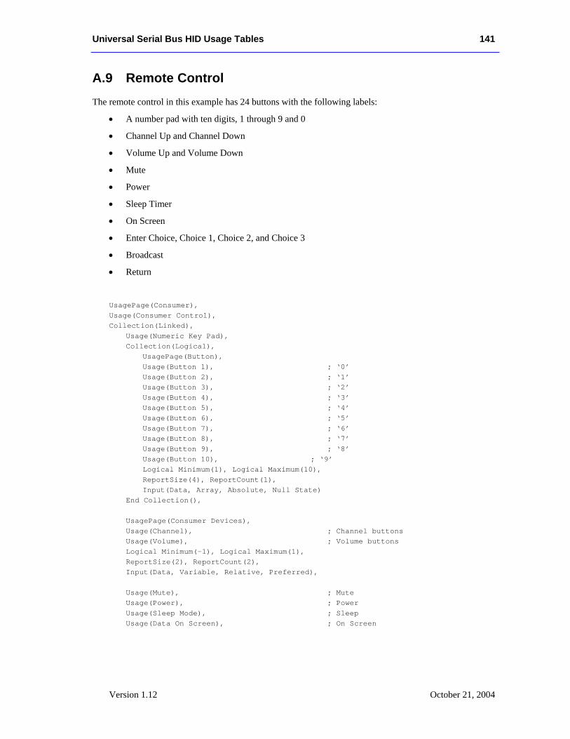
Universal Serial Bus HID Usage Tables 141
Version 1.12 October 21, 2004
A.9 Remote Control The remote control in this example has 24 buttons with the following labels:
• A number pad with ten digits, 1 through 9 and 0
• Channel Up and Channel Down
• Volume Up and Volume Down
• Mute
• Power
• Sleep Timer
• On Screen
• Enter Choice, Choice 1, Choice 2, and Choice 3
• Broadcast
• Return
UsagePage(Consumer), Usage(Consumer Control), Collection(Linked), Usage(Numeric Key Pad), Collection(Logical), UsagePage(Button), Usage(Button 1), ; ‘0’ Usage(Button 2), ; ‘1’ Usage(Button 3), ; ‘2’ Usage(Button 4), ; ‘3’ Usage(Button 5), ; ‘4’ Usage(Button 6), ; ‘5’ Usage(Button 7), ; ‘6’ Usage(Button 8), ; ‘7’ Usage(Button 9), ; ‘8’ Usage(Button 10), ; ‘9’ Logical Minimum(1), Logical Maximum(10), ReportSize(4), ReportCount(1), Input(Data, Array, Absolute, Null State) End Collection(), UsagePage(Consumer Devices), Usage(Channel), ; Channel buttons Usage(Volume), ; Volume buttons Logical Minimum(-1), Logical Maximum(1), ReportSize(2), ReportCount(2), Input(Data, Variable, Relative, Preferred), Usage(Mute), ; Mute Usage(Power), ; Power Usage(Sleep Mode), ; Sleep Usage(Data On Screen), ; On Screen
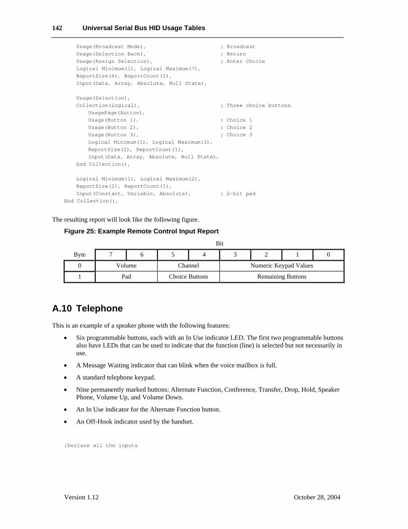
142 Universal Serial Bus HID Usage Tables
Version 1.12 October 28, 2004
Usage(Broadcast Mode), ; Broadcast Usage(Selection Back), ; Return Usage(Assign Selection), ; Enter Choice Logical Minimum(1), Logical Maximum(7), ReportSize(4), ReportCount(1), Input(Data, Array, Absolute, Null State), Usage(Selection), Collection(Logical), ; Three choice buttons UsagePage(Button), Usage(Button 1), ; Choice 1 Usage(Button 2), ; Choice 2 Usage(Button 3), ; Choice 3 Logical Minimum(1), Logical Maximum(3), ReportSize(2), ReportCount(1), Input(Data, Array, Absolute, Null State), End Collection(), Logical Minimum(1), Logical Maximum(2), ReportSize(2), ReportCount(1), Input(Constant, Variable, Absolute), ; 2-bit pad End Collection(),
The resulting report will look like the following figure.
Figure 25: Example Remote Control Input Report
Bit
Byte 7 6 5 4 3 2 1 0
0 Volume Channel Numeric Keypad Values
1 Pad Choice Buttons Remaining Buttons
A.10 Telephone This is an example of a speaker phone with the following features:
• Six programmable buttons, each with an In Use indicator LED. The first two programmable buttons also have LEDs that can be used to indicate that the function (line) is selected but not necessarily in use.
• A Message Waiting indicator that can blink when the voice mailbox is full.
• A standard telephone keypad.
• Nine permanently marked buttons: Alternate Function, Conference, Transfer, Drop, Hold, Speaker Phone, Volume Up, and Volume Down.
• An In Use indicator for the Alternate Function button.
• An Off-Hook indicator used by the handset.
;Declare all the inputs
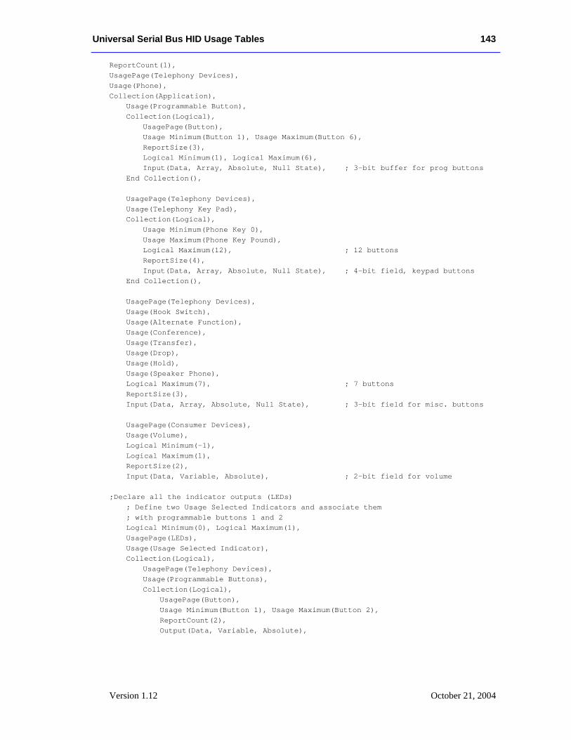
Universal Serial Bus HID Usage Tables 143
Version 1.12 October 21, 2004
ReportCount(1), UsagePage(Telephony Devices), Usage(Phone), Collection(Application), Usage(Programmable Button), Collection(Logical), UsagePage(Button), Usage Minimum(Button 1), Usage Maximum(Button 6), ReportSize(3), Logical Minimum(1), Logical Maximum(6), Input(Data, Array, Absolute, Null State), ; 3-bit buffer for prog buttons End Collection(), UsagePage(Telephony Devices), Usage(Telephony Key Pad), Collection(Logical), Usage Minimum(Phone Key 0), Usage Maximum(Phone Key Pound), Logical Maximum(12), ; 12 buttons ReportSize(4), Input(Data, Array, Absolute, Null State), ; 4-bit field, keypad buttons End Collection(), UsagePage(Telephony Devices), Usage(Hook Switch), Usage(Alternate Function), Usage(Conference), Usage(Transfer), Usage(Drop), Usage(Hold), Usage(Speaker Phone), Logical Maximum(7), ; 7 buttons ReportSize(3), Input(Data, Array, Absolute, Null State), ; 3-bit field for misc. buttons UsagePage(Consumer Devices), Usage(Volume), Logical Minimum(-1), Logical Maximum(1), ReportSize(2), Input(Data, Variable, Absolute), ; 2-bit field for volume ;Declare all the indicator outputs (LEDs) ; Define two Usage Selected Indicators and associate them ; with programmable buttons 1 and 2 Logical Minimum(0), Logical Maximum(1), UsagePage(LEDs), Usage(Usage Selected Indicator), Collection(Logical), UsagePage(Telephony Devices), Usage(Programmable Buttons), Collection(Logical), UsagePage(Button), Usage Minimum(Button 1), Usage Maximum(Button 2), ReportCount(2), Output(Data, Variable, Absolute),
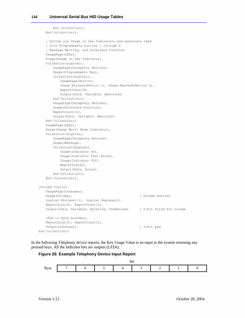
144 Universal Serial Bus HID Usage Tables
Version 1.12 October 28, 2004
End Collection(), End Collection(), ; Define six Usage In Use Indicators and associate them ; with Programmable buttons 1 through 6 ; Message Waiting, and Alternate Function UsagePage(LEDs), Usage(Usage In Use Indicator), Collection(Logical), UsagePage(Telephony Devices), Usage(Programmable Key), Collection(Logical), UsagePage(Button), Usage Minimum(Button 1), Usage Maximum(Button 6), ReportCount(6), Output(Data, Variable, Absolute), End Collection(), UsagePage(Telephony Devices), Usage(Alternate Function), ReportCount(1), Output(Data, Variable, Absolute), End Collection(), UsagePage(LEDs), Usage(Usage Multi Mode Indicator), Collection(Logical), UsagePage(Telephony Devices), Usage(Message), Collection(Logical), Usage(Indicator On), Usage(Indicator Fast Blink), Usage(Indicator Off), ReportSize(2), Output(Data, Array), End Collection(), End Collection(), ;Volume Control UsagePage(Consumer), Usage(Volume), ; Volume buttons Logical Minimum(-1), Logical Maximum(1), ReportSize(2), ReportCount(1), Output(Data, Variable, Relative, Preferred), ; 2-bit field for volume ;Pad to byte boundary ReportSize(3), ReportCount(1), Output(Constant), ; 3-bit pad End Collection()
In the following Telephony device reports, the Key Usage Value is an input to the system returning any pressed keys. All the Indicator bits are outputs (LEDs).
Figure 26: Example Telephony Device Input Report
Bit
Byte 7 6 5 4 3 2 1 0
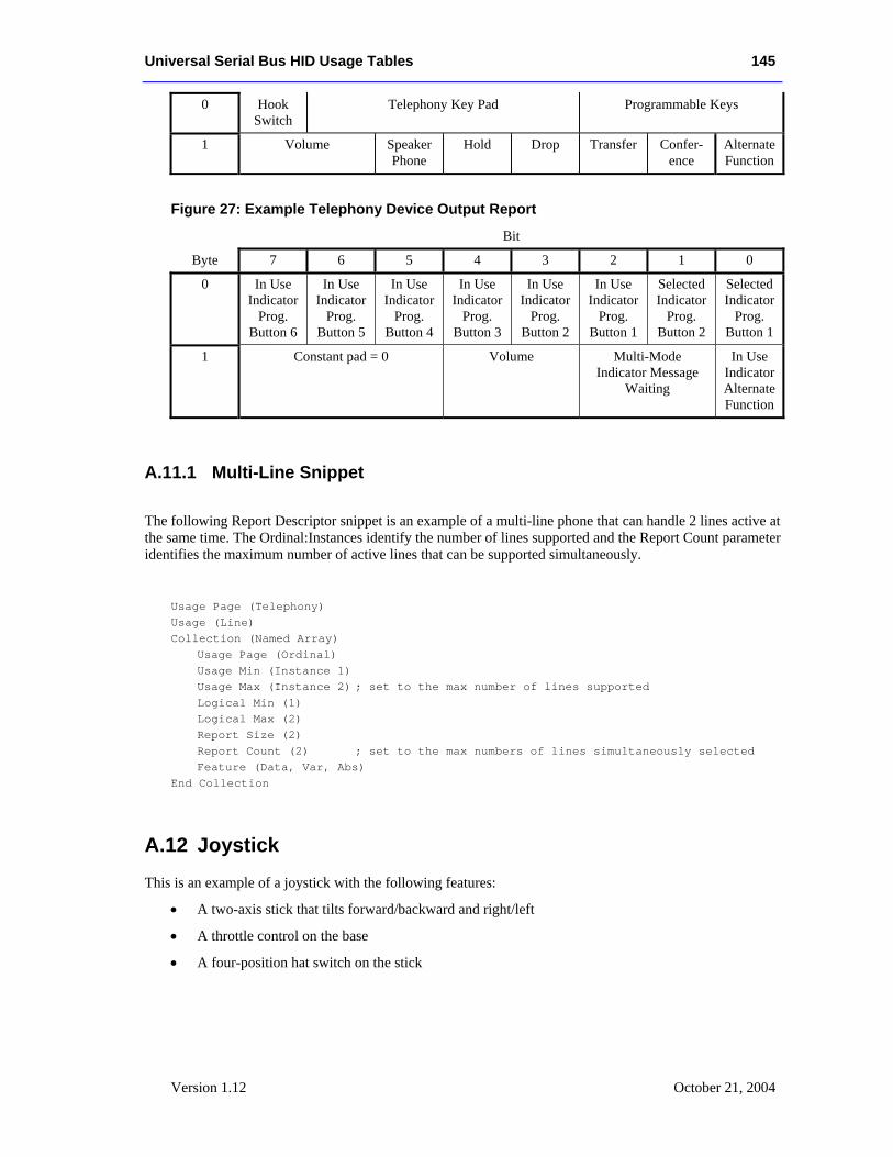
Universal Serial Bus HID Usage Tables 145
Version 1.12 October 21, 2004
0 Hook Switch
Telephony Key Pad Programmable Keys
1 Volume Speaker Phone
Hold Drop Transfer Confer-ence
Alternate Function
Figure 27: Example Telephony Device Output Report
Bit
Byte 7 6 5 4 3 2 1 0
0 In Use Indicator
Prog. Button 6
In Use Indicator
Prog. Button 5
In Use Indicator
Prog. Button 4
In Use Indicator
Prog. Button 3
In Use Indicator
Prog. Button 2
In Use Indicator
Prog. Button 1
Selected Indicator
Prog. Button 2
Selected Indicator
Prog. Button 1
1 Constant pad = 0 Volume Multi-Mode Indicator Message
Waiting
In Use Indicator Alternate Function
A.11.1 Multi-Line Snippet
The following Report Descriptor snippet is an example of a multi-line phone that can handle 2 lines active at the same time. The Ordinal:Instances identify the number of lines supported and the Report Count parameter identifies the maximum number of active lines that can be supported simultaneously.
Usage Page (Telephony) Usage (Line) Collection (Named Array) Usage Page (Ordinal) Usage Min (Instance 1) Usage Max (Instance 2) ; set to the max number of lines supported Logical Min (1) Logical Max (2) Report Size (2) Report Count (2) ; set to the max numbers of lines simultaneously selected Feature (Data, Var, Abs) End Collection
A.12 Joystick
This is an example of a joystick with the following features:
• A two-axis stick that tilts forward/backward and right/left
• A throttle control on the base
• A four-position hat switch on the stick
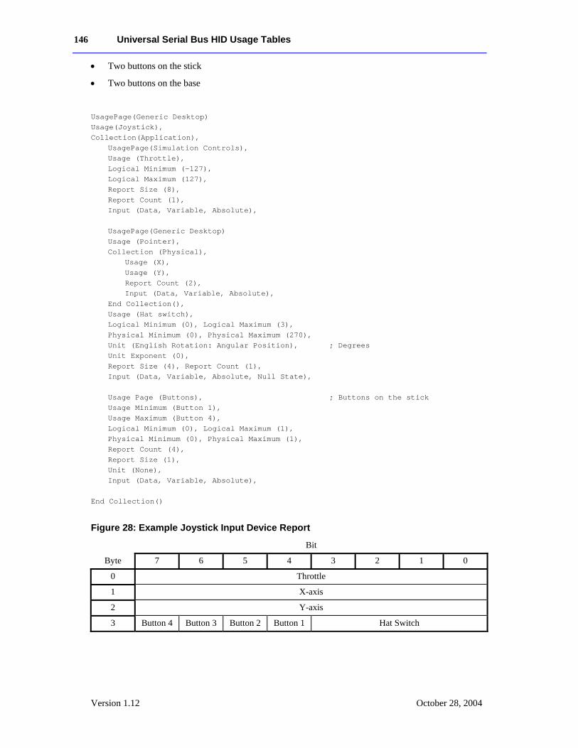
146 Universal Serial Bus HID Usage Tables
Version 1.12 October 28, 2004
• Two buttons on the stick
• Two buttons on the base
UsagePage(Generic Desktop) Usage(Joystick), Collection(Application), UsagePage(Simulation Controls), Usage (Throttle), Logical Minimum (-127), Logical Maximum (127), Report Size (8), Report Count (1), Input (Data, Variable, Absolute), UsagePage(Generic Desktop) Usage (Pointer), Collection (Physical), Usage (X), Usage (Y), Report Count (2), Input (Data, Variable, Absolute),
End Collection(), Usage (Hat switch), Logical Minimum (0), Logical Maximum (3), Physical Minimum (0), Physical Maximum (270), Unit (English Rotation: Angular Position), ; Degrees Unit Exponent (0),
Report Size (4), Report Count (1), Input (Data, Variable, Absolute, Null State), Usage Page (Buttons), ; Buttons on the stick Usage Minimum (Button 1), Usage Maximum (Button 4), Logical Minimum (0), Logical Maximum (1), Physical Minimum (0), Physical Maximum (1), Report Count (4), Report Size (1), Unit (None), Input (Data, Variable, Absolute), End Collection()
Figure 28: Example Joystick Input Device Report
Bit
Byte 7 6 5 4 3 2 1 0
0 Throttle
1 X-axis
2 Y-axis
3 Button 4 Button 3 Button 2 Button 1 Hat Switch
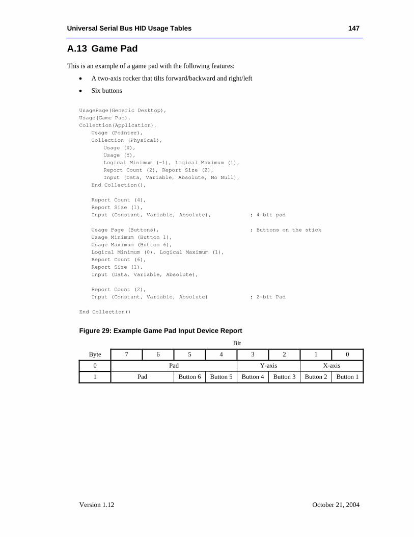
Universal Serial Bus HID Usage Tables 147
Version 1.12 October 21, 2004
A.13 Game Pad This is an example of a game pad with the following features:
• A two-axis rocker that tilts forward/backward and right/left
• Six buttons
UsagePage(Generic Desktop), Usage(Game Pad), Collection(Application), Usage (Pointer), Collection (Physical), Usage (X), Usage (Y), Logical Minimum (-1), Logical Maximum (1), Report Count (2), Report Size (2), Input (Data, Variable, Absolute, No Null),
End Collection(), Report Count (4), Report Size (1), Input (Constant, Variable, Absolute), ; 4-bit pad Usage Page (Buttons), ; Buttons on the stick Usage Minimum (Button 1), Usage Maximum (Button 6), Logical Minimum (0), Logical Maximum (1), Report Count (6), Report Size (1), Input (Data, Variable, Absolute), Report Count (2), Input (Constant, Variable, Absolute) ; 2-bit Pad End Collection()
Figure 29: Example Game Pad Input Device Report
Bit
Byte 7 6 5 4 3 2 1 0
0 Pad Y-axis X-axis
1 Pad Button 6 Button 5 Button 4 Button 3 Button 2 Button 1
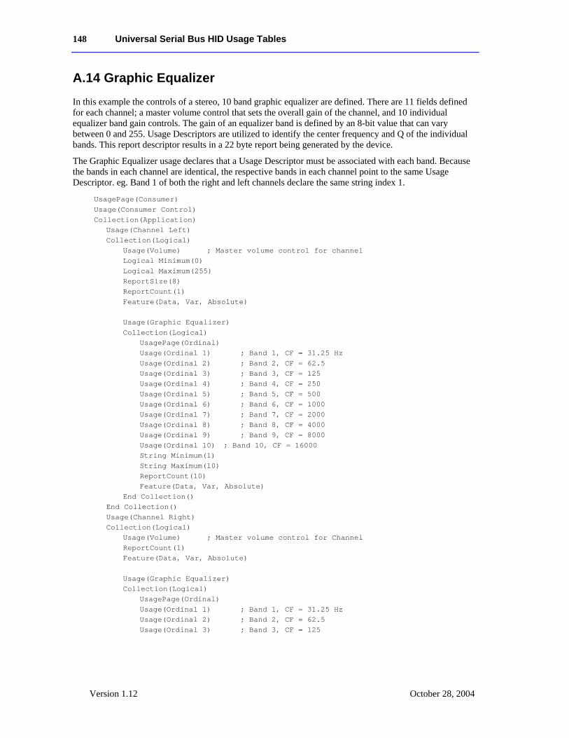
148 Universal Serial Bus HID Usage Tables
Version 1.12 October 28, 2004
A.14 Graphic Equalizer In this example the controls of a stereo, 10 band graphic equalizer are defined. There are 11 fields defined for each channel; a master volume control that sets the overall gain of the channel, and 10 individual equalizer band gain controls. The gain of an equalizer band is defined by an 8-bit value that can vary between 0 and 255. Usage Descriptors are utilized to identify the center frequency and Q of the individual bands. This report descriptor results in a 22 byte report being generated by the device.
The Graphic Equalizer usage declares that a Usage Descriptor must be associated with each band. Because the bands in each channel are identical, the respective bands in each channel point to the same Usage Descriptor. eg. Band 1 of both the right and left channels declare the same string index 1.
UsagePage(Consumer) Usage(Consumer Control) Collection(Application) Usage(Channel Left) Collection(Logical) Usage(Volume) ; Master volume control for channel Logical Minimum(0) Logical Maximum(255) ReportSize(8) ReportCount(1) Feature(Data, Var, Absolute) Usage(Graphic Equalizer) Collection(Logical) UsagePage(Ordinal) Usage(Ordinal 1) ; Band 1, CF = 31.25 Hz Usage(Ordinal 2) ; Band 2, CF = 62.5 Usage(Ordinal 3) ; Band 3, CF = 125 Usage(Ordinal 4) ; Band 4, CF = 250 Usage(Ordinal 5) ; Band 5, CF = 500 Usage(Ordinal 6) ; Band 6, CF = 1000 Usage(Ordinal 7) ; Band 7, CF = 2000 Usage(Ordinal 8) ; Band 8, CF = 4000 Usage(Ordinal 9) ; Band 9, CF = 8000 Usage(Ordinal 10) ; Band 10, CF = 16000 String Minimum(1) String Maximum(10) ReportCount(10) Feature(Data, Var, Absolute) End Collection() End Collection() Usage(Channel Right) Collection(Logical) Usage(Volume) ; Master volume control for Channel ReportCount(1) Feature(Data, Var, Absolute) Usage(Graphic Equalizer) Collection(Logical) UsagePage(Ordinal) Usage(Ordinal 1) ; Band 1, CF = 31.25 Hz Usage(Ordinal 2) ; Band 2, CF = 62.5 Usage(Ordinal 3) ; Band 3, CF = 125
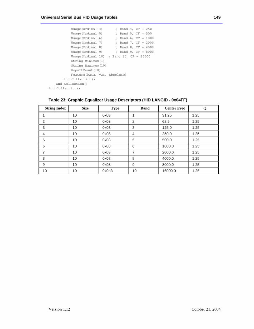
Universal Serial Bus HID Usage Tables 149
Version 1.12 October 21, 2004
Usage(Ordinal 4) ; Band 4, CF = 250 Usage(Ordinal 5) ; Band 5, CF = 500 Usage(Ordinal 6) ; Band 6, CF = 1000 Usage(Ordinal 7) ; Band 7, CF = 2000 Usage(Ordinal 8) ; Band 8, CF = 4000 Usage(Ordinal 9) ; Band 9, CF = 8000 Usage(Ordinal 10) ; Band 10, CF = 16000 String Minimum(1) String Maximum(10) ReportCount(10) Feature(Data, Var, Absolute) End Collection() End Collection() End Collection()
Table 23: Graphic Equalizer Usage Descriptors (HID LANGID - 0x04FF)
String Index Size Type Band Center Freq Q
1 10 0x03 1 31.25 1.25 2 10 0x03 2 62.5 1.25 3 10 0x03 3 125.0 1.25 4 10 0x03 4 250.0 1.25 5 10 0x03 5 500.0 1.25 6 10 0x03 6 1000.0 1.25 7 10 0x03 7 2000.0 1.25 8 10 0x03 8 4000.0 1.25 9 10 0x93 9 8000.0 1.25 10 10 0x0b3 10 16000.0 1.25
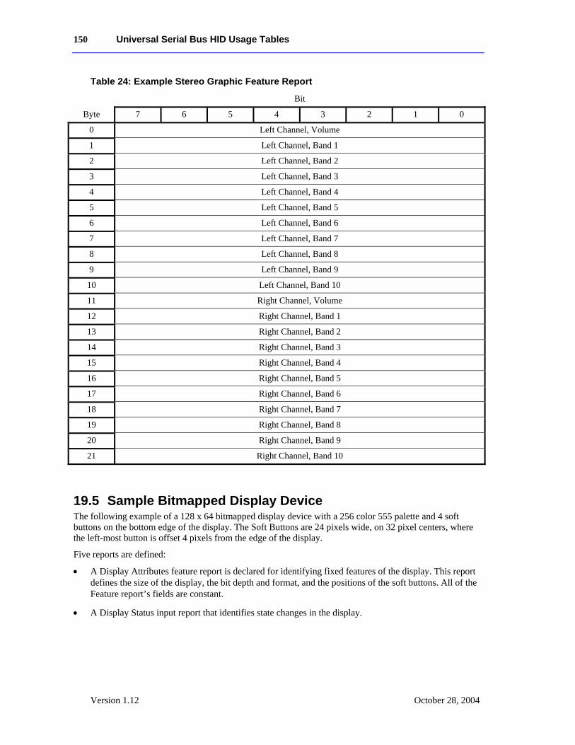
150 Universal Serial Bus HID Usage Tables
Version 1.12 October 28, 2004
Table 24: Example Stereo Graphic Feature Report
Bit
Byte 7 6 5 4 3 2 1 0
0 Left Channel, Volume
1 Left Channel, Band 1
2 Left Channel, Band 2
3 Left Channel, Band 3
4 Left Channel, Band 4
5 Left Channel, Band 5
6 Left Channel, Band 6
7 Left Channel, Band 7
8 Left Channel, Band 8
9 Left Channel, Band 9
10 Left Channel, Band 10
11 Right Channel, Volume
12 Right Channel, Band 1
13 Right Channel, Band 2
14 Right Channel, Band 3
15 Right Channel, Band 4
16 Right Channel, Band 5
17 Right Channel, Band 6
18 Right Channel, Band 7
19 Right Channel, Band 8
20 Right Channel, Band 9
21 Right Channel, Band 10
19.5 Sample Bitmapped Display Device The following example of a 128 x 64 bitmapped display device with a 256 color 555 palette and 4 soft buttons on the bottom edge of the display. The Soft Buttons are 24 pixels wide, on 32 pixel centers, where the left-most button is offset 4 pixels from the edge of the display.
Five reports are defined:
• A Display Attributes feature report is declared for identifying fixed features of the display. This report defines the size of the display, the bit depth and format, and the positions of the soft buttons. All of the Feature report’s fields are constant.
• A Display Status input report that identifies state changes in the display.
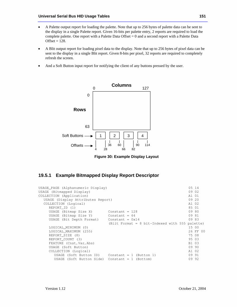
Universal Serial Bus HID Usage Tables 151
Version 1.12 October 21, 2004
• A Palette output report for loading the palette. Note that up to 256 bytes of palette data can be sent to the display in a single Palette report. Given 16-bits per palette entry, 2 reports are required to load the complete palette. One report with a Palette Data Offset = 0 and a second report with a Palette Data Offset = 128.
• A Blit output report for loading pixel data to the display. Note that up to 256 bytes of pixel data can be sent to the display in a single Blit report. Given 8-bits per pixel, 32 reports are required to completely refresh the screen.
• And a Soft Button input report for notifying the client of any buttons pressed by the user.
Figure 30: Example Display Layout
19.5.1 Example Bitmapped Display Report Descriptor USAGE_PAGE (Alphanumeric Display) 05 14 USAGE (Bitmapped Display) 09 02 COLLECTION (Application) A1 01 USAGE (Display Attributes Report) 09 20 COLLECTION (Logical) A1 02 REPORT_ID (1) 85 01 USAGE (Bitmap Size X) Constant = 128 09 80 USAGE (Bitmap Size Y) Constant = 64 09 81 USAGE (Bit Depth Format) Constant = 0x14 09 83 (Blit Format = 8 bit-Indexed with 555 palette) LOGICAL_MINIMUM (0) 15 00 LOGICAL_MAXIMUM (255) 26 FF 00 REPORT_SIZE (8) 75 08 REPORT_COUNT (3) 95 03 FEATURE (Cnst,Var,Abs) B1 03 USAGE (Soft Button) 09 90 COLLECTION (Logical) A1 02 USAGE (Soft Button ID) Constant = 1 (Button 1) 09 91 USAGE (Soft Button Side) Constant = 1 (Bottom) 09 92
0 127
0
63
Columns
Rows
1
4 28
2
36 60
3
66 82
4
90 114
Soft Buttons
Offsets
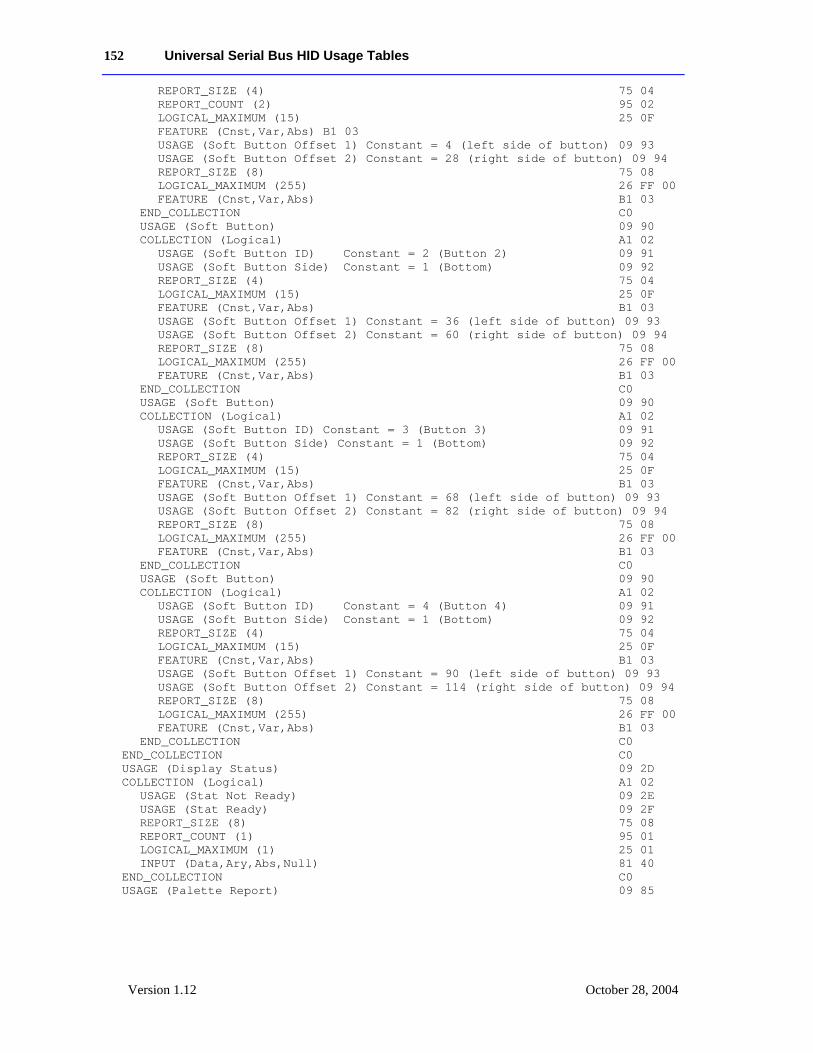
152 Universal Serial Bus HID Usage Tables
Version 1.12 October 28, 2004
REPORT_SIZE (4) 75 04 REPORT_COUNT (2) 95 02 LOGICAL_MAXIMUM (15) 25 0F FEATURE (Cnst,Var,Abs) B1 03 USAGE (Soft Button Offset 1) Constant = 4 (left side of button) 09 93 USAGE (Soft Button Offset 2) Constant = 28 (right side of button) 09 94 REPORT_SIZE (8) 75 08 LOGICAL_MAXIMUM (255) 26 FF 00 FEATURE (Cnst,Var,Abs) B1 03 END_COLLECTION C0 USAGE (Soft Button) 09 90 COLLECTION (Logical) A1 02 USAGE (Soft Button ID) Constant = 2 (Button 2) 09 91 USAGE (Soft Button Side) Constant = 1 (Bottom) 09 92 REPORT_SIZE (4) 75 04 LOGICAL_MAXIMUM (15) 25 0F FEATURE (Cnst,Var,Abs) B1 03 USAGE (Soft Button Offset 1) Constant = 36 (left side of button) 09 93 USAGE (Soft Button Offset 2) Constant = 60 (right side of button) 09 94 REPORT_SIZE (8) 75 08 LOGICAL_MAXIMUM (255) 26 FF 00 FEATURE (Cnst,Var,Abs) B1 03 END_COLLECTION C0 USAGE (Soft Button) 09 90 COLLECTION (Logical) A1 02 USAGE (Soft Button ID) Constant = 3 (Button 3) 09 91 USAGE (Soft Button Side) Constant = 1 (Bottom) 09 92 REPORT_SIZE (4) 75 04 LOGICAL_MAXIMUM (15) 25 0F FEATURE (Cnst,Var,Abs) B1 03 USAGE (Soft Button Offset 1) Constant = 68 (left side of button) 09 93 USAGE (Soft Button Offset 2) Constant = 82 (right side of button) 09 94 REPORT_SIZE (8) 75 08 LOGICAL_MAXIMUM (255) 26 FF 00 FEATURE (Cnst,Var,Abs) B1 03 END_COLLECTION C0 USAGE (Soft Button) 09 90 COLLECTION (Logical) A1 02 USAGE (Soft Button ID) Constant = 4 (Button 4) 09 91 USAGE (Soft Button Side) Constant = 1 (Bottom) 09 92 REPORT_SIZE (4) 75 04 LOGICAL_MAXIMUM (15) 25 0F FEATURE (Cnst,Var,Abs) B1 03 USAGE (Soft Button Offset 1) Constant = 90 (left side of button) 09 93 USAGE (Soft Button Offset 2) Constant = 114 (right side of button) 09 94 REPORT_SIZE (8) 75 08 LOGICAL_MAXIMUM (255) 26 FF 00 FEATURE (Cnst,Var,Abs) B1 03 END_COLLECTION C0 END_COLLECTION C0 USAGE (Display Status) 09 2D COLLECTION (Logical) A1 02 USAGE (Stat Not Ready) 09 2E USAGE (Stat Ready) 09 2F REPORT_SIZE (8) 75 08 REPORT_COUNT (1) 95 01 LOGICAL_MAXIMUM (1) 25 01 INPUT (Data,Ary,Abs,Null) 81 40 END_COLLECTION C0 USAGE (Palette Report) 09 85
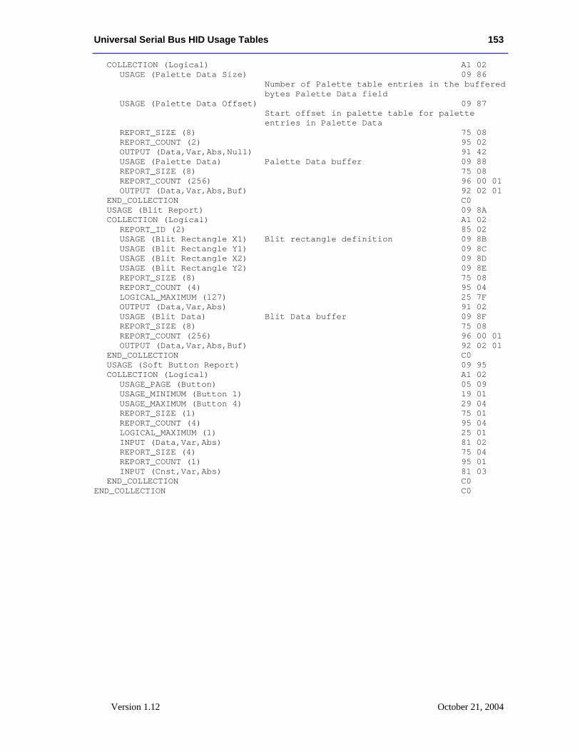
Universal Serial Bus HID Usage Tables 153
Version 1.12 October 21, 2004
COLLECTION (Logical) A1 02 USAGE (Palette Data Size) 09 86 Number of Palette table entries in the buffered bytes Palette Data field USAGE (Palette Data Offset) 09 87 Start offset in palette table for palette entries in Palette Data REPORT_SIZE (8) 75 08 REPORT_COUNT (2) 95 02 OUTPUT (Data,Var,Abs,Null) 91 42 USAGE (Palette Data) Palette Data buffer 09 88 REPORT_SIZE (8) 75 08 REPORT_COUNT (256) 96 00 01 OUTPUT (Data,Var,Abs,Buf) 92 02 01 END_COLLECTION C0 USAGE (Blit Report) 09 8A COLLECTION (Logical) A1 02 REPORT_ID (2) 85 02 USAGE (Blit Rectangle X1) Blit rectangle definition 09 8B USAGE (Blit Rectangle Y1) 09 8C USAGE (Blit Rectangle X2) 09 8D USAGE (Blit Rectangle Y2) 09 8E REPORT_SIZE (8) 75 08 REPORT_COUNT (4) 95 04 LOGICAL_MAXIMUM (127) 25 7F OUTPUT (Data,Var,Abs) 91 02 USAGE (Blit Data) Blit Data buffer 09 8F REPORT_SIZE (8) 75 08 REPORT_COUNT (256) 96 00 01 OUTPUT (Data,Var,Abs,Buf) 92 02 01 END_COLLECTION C0 USAGE (Soft Button Report) 09 95 COLLECTION (Logical) A1 02 USAGE_PAGE (Button) 05 09 USAGE_MINIMUM (Button 1) 19 01 USAGE_MAXIMUM (Button 4) 29 04 REPORT_SIZE (1) 75 01 REPORT_COUNT (4) 95 04 LOGICAL_MAXIMUM (1) 25 01 INPUT (Data,Var,Abs) 81 02 REPORT_SIZE (4) 75 04 REPORT_COUNT (1) 95 01 INPUT (Cnst,Var,Abs) 81 03 END_COLLECTION C0 END_COLLECTION C0
154 Universal Serial Bus HID Usage Tables
Version 1.12 October 28, 2004
Appendix B: Delimiter Example Delimiters allow a device to declare multiple uses for a control.
Ideally, an application like a flight simulator would look for the controls that are specific to it. It would first search for Flight Simulation Devices attached to the system and then, if one was found, it would look for controls (usages) such as Flight Control Stick, Trigger, Rudder, Throttle, Landing Gear, Toe Brake, etc. The problem with a Flight Stick declaring these usages is that the same device can also be used as a generic joystick. A device declaring itself as a Flight Simulation Device would not be found by an application that searched for a Joystick usage.
A problem that occurs with generic buttons on an application-specific device such as a Flight Stick is that different applications use the same buttons for different purposes, forcing the user to relearn the buttons for each application.
Delimiters solve this problem by allowing multiple usages to be associated with a device or an individual control. Using delimiters, a hardware vendor can suggest usages for the buttons that will allow a consistent user interface across applications.
Delimiters are not allowed on top-level collections or arrays. The following example is a single device that can also be identified as a Flight Simulation Device, a Flight Stick or a generic Joystick. Most of the controls also have alternate mappings:
• The axes of the stick are either a Flight Control Stick or a Pointer.
• The hat switch can also be used as a Point of View control.
• Each of the four buttons have alternate mappings:
− Button 1 or Trigger
− Button 2 or Weapons Select
− Button 3, Electronic Counter Measures, or Flare Release
− Button 4, Landing Gear, or Chaff Release
Buttons 3 and 4 thus have two alternate usages.
Note that the report generated by this Report descriptor is identical to that generated by the joystick example in Appendix A.
UsagePage(Generic Desktop), LogicalMin(0), Usage (Joystick), Collection(Application) UsagePage(Simulation Controls), Usage (Throttle), Logical Minimum (-127), Logical Maximum (127), Report Size (8), Report Count (1), Input (Data, Variable, Absolute), Delimiter(Open), Usage (Flight Control Stick), Usage (Generic Desktop: Pointer), Delimiter(Close),
Note
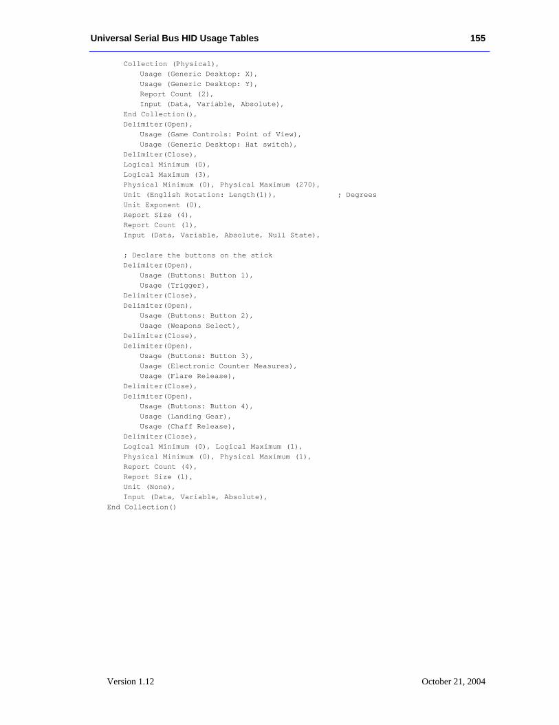
Universal Serial Bus HID Usage Tables 155
Version 1.12 October 21, 2004
Collection (Physical), Usage (Generic Desktop: X), Usage (Generic Desktop: Y), Report Count (2), Input (Data, Variable, Absolute), End Collection(), Delimiter(Open), Usage (Game Controls: Point of View), Usage (Generic Desktop: Hat switch), Delimiter(Close), Logical Minimum (0), Logical Maximum (3), Physical Minimum (0), Physical Maximum (270), Unit (English Rotation: Length(1)), ; Degrees Unit Exponent (0), Report Size (4), Report Count (1), Input (Data, Variable, Absolute, Null State), ; Declare the buttons on the stick Delimiter(Open), Usage (Buttons: Button 1), Usage (Trigger), Delimiter(Close), Delimiter(Open), Usage (Buttons: Button 2), Usage (Weapons Select), Delimiter(Close), Delimiter(Open), Usage (Buttons: Button 3), Usage (Electronic Counter Measures), Usage (Flare Release), Delimiter(Close), Delimiter(Open), Usage (Buttons: Button 4), Usage (Landing Gear), Usage (Chaff Release), Delimiter(Close), Logical Minimum (0), Logical Maximum (1), Physical Minimum (0), Physical Maximum (1), Report Count (4), Report Size (1), Unit (None), Input (Data, Variable, Absolute), End Collection()
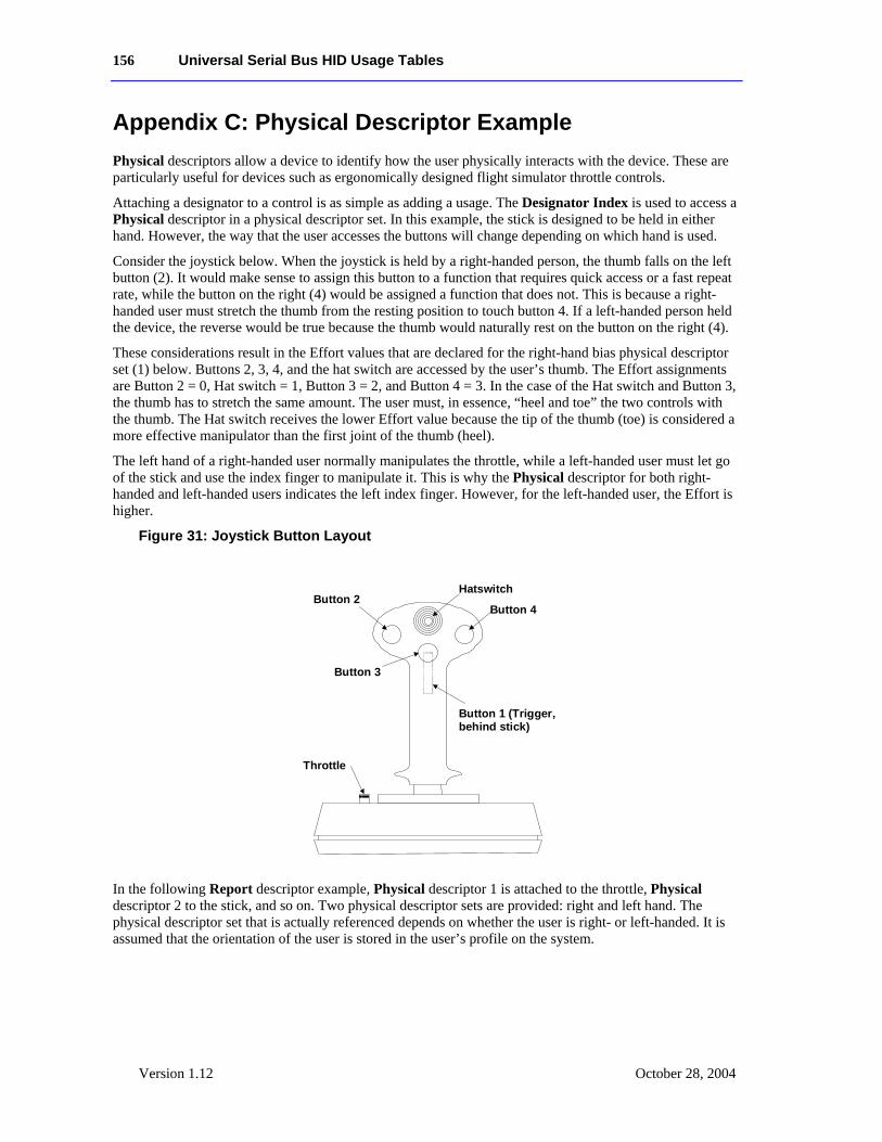
156 Universal Serial Bus HID Usage Tables
Version 1.12 October 28, 2004
Appendix C: Physical Descriptor Example Physical descriptors allow a device to identify how the user physically interacts with the device. These are particularly useful for devices such as ergonomically designed flight simulator throttle controls.
Attaching a designator to a control is as simple as adding a usage. The Designator Index is used to access a Physical descriptor in a physical descriptor set. In this example, the stick is designed to be held in either hand. However, the way that the user accesses the buttons will change depending on which hand is used.
Consider the joystick below. When the joystick is held by a right-handed person, the thumb falls on the left button (2). It would make sense to assign this button to a function that requires quick access or a fast repeat rate, while the button on the right (4) would be assigned a function that does not. This is because a right-handed user must stretch the thumb from the resting position to touch button 4. If a left-handed person held the device, the reverse would be true because the thumb would naturally rest on the button on the right (4).
These considerations result in the Effort values that are declared for the right-hand bias physical descriptor set (1) below. Buttons 2, 3, 4, and the hat switch are accessed by the user’s thumb. The Effort assignments are Button 2 = 0, Hat switch = 1, Button 3 = 2, and Button 4 = 3. In the case of the Hat switch and Button 3, the thumb has to stretch the same amount. The user must, in essence, “heel and toe” the two controls with the thumb. The Hat switch receives the lower Effort value because the tip of the thumb (toe) is considered a more effective manipulator than the first joint of the thumb (heel).
The left hand of a right-handed user normally manipulates the throttle, while a left-handed user must let go of the stick and use the index finger to manipulate it. This is why the Physical descriptor for both right-handed and left-handed users indicates the left index finger. However, for the left-handed user, the Effort is higher.
Figure 31: Joystick Button Layout
Hatswitch
Button 4
Button 3
Button 2
Button 1 (Trigger,behind stick)
Throttle
In the following Report descriptor example, Physical descriptor 1 is attached to the throttle, Physical descriptor 2 to the stick, and so on. Two physical descriptor sets are provided: right and left hand. The physical descriptor set that is actually referenced depends on whether the user is right- or left-handed. It is assumed that the orientation of the user is stored in the user’s profile on the system.
Universal Serial Bus HID Usage Tables 157
Version 1.12 October 21, 2004
Usage Page (Generic Desktop), Logical Minimum (0), Usage (Joystick), Collection (Application), Usage Page (Simulation Controls), Usage (Throttle), Designator Index (1), Logical Minimum (-127), Logical Maximum (127), Report Size (8), Report Count (1), Input (Data, Variable, Absolute), Usage Page (Generic Desktop), Designator Index(2), Usage (Pointer), Collection (Physical), Usage (X), Usage (Y), Report Count (2), Input (Data, Variable, Absolute), End Collection(), Usage (Hat switch), Designator Index (3), Logical Minimum (0), Logical Maximum (3), Physical Minimum (0), Physical Maximum (270), Unit (English Rotation: Angular Position), ; Degrees Unit Exponent (0), Report Size (4), Report Count (1), Input (Data, Variable, Absolute, Null State), Usage Page (Buttons), ; Buttons on the stick Usage Minimum (Button 1), Usage Maximum (Button 4), Physical Minimum (4), Physical Maximum (7), Logical Minimum (0), Logical Maximum (1), Physical Minimum (0), Physical Maximum (1), Report Count (4), Report Size (1), Unit (None), Input (Data, Variable, Absolute), End Collection()
The following notation is used to describe two physical descriptor sets for right-handed and left-handed use.
; There are two sets defined. Descriptor set 0 is a special descriptor set ; that specifies the number of additional descriptor sets, ; and also the number of Physical Descriptors in each set. Physical Descriptor Set [0] { Physical Descriptor Set Count (2) Physical Descriptor Set Length (15) ; In bytes }
158 Universal Serial Bus HID Usage Tables
Version 1.12 October 28, 2004
Physical Descriptor Set [1] { Bias(Right Hand) Preference (0) Physical Descriptor [1] ; Throttle Designator (Index Finger) Qualifier (Left) Effort (0) Physical Descriptor [2] ; Stick Designator (Hand) Qualifier (Right) Effort (0) Physical Descriptor [3] ; Hat switch Designator (Thumb) Qualifier (Right) Effort (1) Physical Descriptor [4] ; Button 1 – Trigger Designator (Index Finger) Qualifier (Right) Effort (0) Physical Descriptor [5] ; Button 2 Designator (Thumb) Qualifier (Right) Effort (0) Physical Descriptor [6] ; Button 3 Designator (Thumb) Qualifier (Right) Effort (2) Physical Descriptor [7] ; Button 4 Designator (Thumb) Qualifier (Right) Effort (3) } Physical Descriptor Set Header [2]{ Bias (Left Hand) Preference (0) Physical Descriptor [1] ; Throttle Designator (Index Finger) Qualifier (Left) Effort (1) Physical Descriptor [2] ; Stick Designator (Hand) Qualifier (Left) Effort (0) Physical Descriptor [3] ; Hat switch Designator (Thumb) Qualifier (Left) Effort (1) Physical Descriptor [4] ; Button 1 – Trigger Designator (Index Finger) Qualifier (Left) Effort (0) Physical Descriptor [5] ; Button 2 Designator (Thumb) Qualifier (Left)
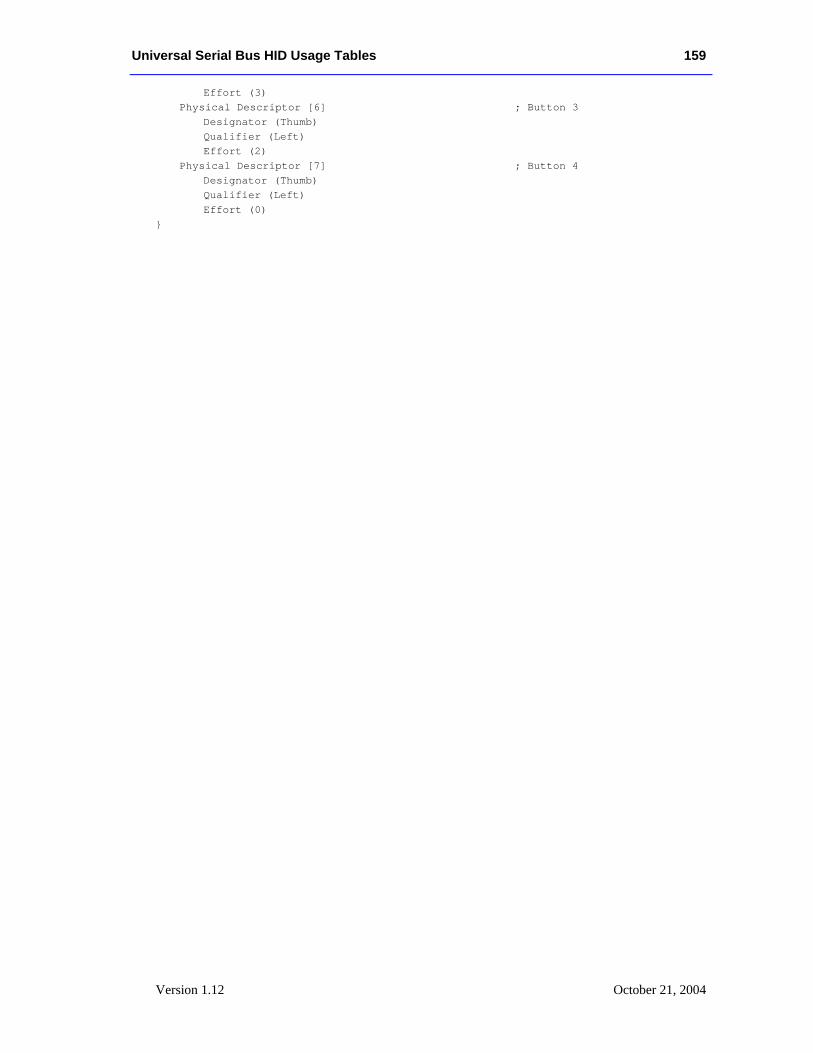
Universal Serial Bus HID Usage Tables 159
Version 1.12 October 21, 2004
Effort (3) Physical Descriptor [6] ; Button 3 Designator (Thumb) Qualifier (Left) Effort (2) Physical Descriptor [7] ; Button 4 Designator (Thumb) Qualifier (Left) Effort (0) }
160 Universal Serial Bus HID Usage Tables
Version 1.12 October 28, 2004
Usage Index
# +10 ....................................................................88 3D Game Controller........................................50 +100 ..................................................................88 3D Digitizer ....................................................107
1 14-Segment Direct Map ..................................115 14-segment displays ........................................124
2 2-D Mode Adjust.............................................132 2-D Mode Select .............................................132
7 7-Segment Direct Map ....................................115 7-segment displays ..........................................122
A AC Add to Cart ...............................................103 AC Align to Grid.............................................105 AC All Caps ....................................................102 AC Attach Comment.......................................104 AC Attach File ................................................104 AC Back..........................................................101 AC Bold ..........................................................102 AC Bookmarks................................................102 AC Bulleted List .............................................103 AC Buy/Checkout ...........................................103 AC Cancel .......................................................103 AC Catalog......................................................103 AC Clear Alarm ..............................................104 AC Close .........................................................101 AC Collapse ....................................................103 AC Collapse All ..............................................103 AC Copy .........................................................101 AC Cut ............................................................101 AC Delete........................................................103 AC Delete Comment .......................................104 AC Demote .....................................................103 AC Distribute H ..............................................105 AC Distribute V ..............................................105 AC Download .................................................104 AC Edit ...........................................................102 AC Edit Time Zones .......................................104 AC Exit ...........................................................101 AC Expand......................................................103 AC Expand All................................................103 AC Filter .........................................................104
AC Find...........................................................101 AC Find and Replace ......................................101 AC Flip horizontal...........................................102 AC Flip Vertical ..............................................102 AC Font Color .................................................103 AC Font Select ................................................103 AC Font Size ...................................................103 AC Format.......................................................102 AC Forward.............................................101, 104 AC Full Screen View ......................................102 AC Go To........................................................101 AC Group ........................................................105 AC History ......................................................102 AC Home.........................................................101 AC Indent Decrease.........................................103 AC Indent Increase..........................................103 AC Insert Column ...........................................105 AC Insert File ..................................................105 AC Insert Mode...............................................103 AC Insert Object..............................................105 AC Insert Picture .............................................105 AC Insert Row.................................................105 AC Insert Symbol............................................105 AC Italics.........................................................102 AC Justify Block .............................................103 AC Justify Bottom...........................................103 AC Justify Center ............................................103 AC Justify Left ................................................103 AC Justify Right..............................................103 AC Justify Top ................................................103 AC Lock ..........................................................103 AC Maximize ..................................................101 AC Merge........................................................105 AC Minimize...................................................101 AC Mirror Horizontal......................................102 AC Mirror Vertical ..........................................103 AC New...........................................................101 AC New Window ............................................102 AC Next Link ..................................................101 AC No .............................................................103 AC Normal View.............................................102 AC Numbered List ..........................................103 AC Open..........................................................101 AC Pan ............................................................102 AC Pan Left.....................................................102 AC Pan Right ..................................................102 AC Paste..........................................................101 AC Paste Special .............................................103 AC Previous Link............................................102 AC Print...........................................................101
Universal Serial Bus HID Usage Tables 161
Version 1.12 October 21, 2004
AC Print Preview ............................................ 103 AC Promote .................................................... 103 AC Properties.................................................. 101 AC Protect ...................................................... 104 AC Redo/Repeat ............................................. 104 AC Refresh ..................................................... 101 AC Rename..................................................... 105 AC Reply ........................................................ 104 AC Reply All .................................................. 104 AC Reset Alarm.............................................. 104 AC Resize ....................................................... 102 AC Restart Numbering ................................... 103 AC Rotate ....................................................... 102 AC Save .......................................................... 101 AC Save and Close ......................................... 105 AC Scroll ........................................................ 102 AC Scroll Down.............................................. 102 AC Scroll Up .................................................. 102 AC Search....................................................... 101 AC Select All .................................................. 101 AC Select Column .......................................... 104 AC Select Object ............................................ 104 AC Select Paragraph ....................................... 104 AC Select Row................................................ 104 AC Select Sentence......................................... 104 AC Select Table .............................................. 104 AC Select Time Zone...................................... 104 AC Select Word .............................................. 104 AC Send.......................................................... 104 AC Send To .................................................... 104 AC Send/Receive............................................ 104 AC Set Alarm.................................................. 104 AC Set Borders ............................................... 105 AC Set Clock .................................................. 104 AC Snooze Alarm........................................... 104 AC Sort ........................................................... 104 AC Sort Ascending ......................................... 104 AC Sort Descending ....................................... 104 AC Split .......................................................... 105 AC Stop .......................................................... 101 AC Strikethrough............................................ 102 AC Subscript................................................... 102 AC Subscriptions ............................................ 102 AC Superscript................................................ 102 AC Synchronize.............................................. 104 AC Tile Horizontally ...................................... 102 AC Tile Vertically .......................................... 102 AC Underline.................................................. 102 AC Undo......................................................... 101 AC Ungroup.................................................... 105 AC Unlock ...................................................... 103 AC Unprotect.................................................. 104 AC Upload ...................................................... 104
AC View Clock...............................................104 AC View Comment.........................................104 AC View Toggle .............................................102 AC Yes............................................................103 AC Zoom ........................................................102 AC Zoom In ....................................................102 AC Zoom Out..................................................102 Accelerator ........................................................41 Aileron ..............................................................39 Aileron Trim .....................................................39 Airplane Simulation Device............................38 AL A/V Capture/Playback ................................98 AL Alarms ........................................................99 AL Audio Browser..........................................100 AL Audio Player .............................................100 AL Calculator....................................................98 AL Calendar/Schedule ......................................98 AL Checkbook/Finance ....................................98 AL Clock...........................................................99 AL Command Line Processor/Run ...................99 AL Consumer Control Configuration Tool .......98 AL Contacts/Address Book...............................98 AL Control Panel ..............................................99 AL Customized Corporate News Browser......100 AL Database App..............................................98 AL Desktop.......................................................99 AL Dictionary ...................................................99 AL Digital Rights............................................100 AL Digital Wallet............................................100 AL Documents ..................................................99 AL Email Reader ..............................................98 AL Encryption...................................................99 AL Entertainment Content Browser................100 AL File Browser................................................99 AL Grammar Check..........................................99 AL Graphics Editor ...........................................98 AL Image Browser............................................99 AL Instant Messaging .....................................100 AL Integrated Help Center................................99 AL Internet Browser .........................................98 AL Keyboard Layout ........................................99 AL LAN/WAN Browser ...................................98 AL Launch Button Configuration Tool.............98 AL Local Machine Browser..............................98 AL Log/Journal/Timecard.................................98 AL Logoff .........................................................99 AL Logon..........................................................99 AL Logon/Logoff..............................................99 AL Market Monitor/Finance Browser.............100 AL Movie Browser .........................................100 AL Network Chat..............................................99 AL Network Conference ...................................98 AL Newsreader .................................................98
162 Universal Serial Bus HID Usage Tables
Version 1.12 October 28, 2004
AL Next Task/Application ................................99 AL OEM Features/ Tips/Tutorial Browser......100 AL OEM Help.................................................100 AL Online Activities Browser.........................100 AL Online Community ...................................100 AL Online Shopping Browser.........................100 AL Power Status ...............................................99 AL Preemptive Halt Task/Application..............99 AL Presentation App.........................................98 AL Previous Task/Application..........................99 AL Process/Task Manager ................................99 AL Programmable Button Configuration Tool .98 AL Remote Networking/ISP Connect...............98 AL Research/Search Browser .........................100 AL Screen Saver ...............................................99 AL Select Task/Application ..............................99 AL SmartCard Information/Help ....................100 AL Spell Check.................................................99 AL Spreadsheet .................................................98 AL Task/Project Manager .................................98 AL Telephony/Dialer ........................................99 AL Terminal Lock/Screensaver ........................99 AL Text Editor ..................................................98 AL Thesaurus....................................................99 AL Virus Protection ..........................................99 AL Voicemail....................................................98 AL Wireless Status............................................99 AL Word Processor...........................................98 AlphaNumeric Display..................................114 Alternate Function.............................................74 Alternate-audio Decrement ...............................97 Alternate-audio Increment.................................97 Altitude............................................................109 AM/PM .............................................................88 Animatronic Device.........................................45 Answer On/Off..................................................75 Answering Machine ........................................73 Anti-Torque Control..........................................39 Application.......................................................12 Application Break .............................................35 Application Debugger Break.............................35 Application Launch Buttons ..........................97 Armature........................................................108 Array field........................................................12 Articulated Arm ............................................107 ASCII Character Set........................................114 Assign Selection................................................89 Attribute Data..................................................118 Attribute Readback..........................................116 Automobile Simulation Device .......................41 Autopilot Enable ...............................................39 Azimuth...........................................................109
B Balance ..............................................................92 Balance Left ......................................................93 Balance Right ....................................................92 Ballast................................................................42 Barrel Elevation.................................................42 Barrel Pressure ................................................108 Barrel Switch...................................................110 Baseball Bat .....................................................47 Bass ...................................................................93 Bass Boost .........................................................93 Bass Decrement.................................................93 Bass Increment ..................................................93 Battery Low.......................................................67 Battery OK ........................................................67 Battery Operation ..............................................67 Battery Strength...............................................109 Belt ....................................................................44 Bicycle Crank....................................................43 Bicycle Simulation Device ...............................43 Bit Depth Format.............................................125 BitDepth 8880 .................................................127 BitDepth ARGB 1555 .....................................126 BitDepth ARGB 8888 .....................................126 BitDepth Indexed 1 Bit....................................125 BitDepth Indexed 2 Bits ..................................125 BitDepth Indexed 4 Bits ..................................126 BitDepth Indexed 8 Bits ..................................126 BitDepth PARGB 8888 ...................................126 BitDepth RGB 555 ..........................................126 BitDepth RGB 565 ..........................................126 BitDepth RGB 888 ..........................................126 Bitmap Size X .................................................125 Bitmap Size Y .................................................125 Blit Data ..........................................................129 Blit Rectangle X1 ............................................129 Blit Rectangle X2 ............................................129 Blit Rectangle Y1 ............................................129 Blit Rectangle Y2 ............................................129 Blit Report .......................................................129 Body Suit ..........................................................44 Brake .................................................................41 Broadcast Mode.................................................89 Bump .................................................................51 Busy...................................................................66 buttons ...............................................................69 Byte Count.........................................................34
C CA .....................................................................20 Call Pickup ........................................................65 Call Waiting Tone .............................................76 Caller ID............................................................75
Universal Serial Bus HID Usage Tables 163
Version 1.12 October 21, 2004
Camera Off ....................................................... 65 Camera On ........................................................ 65 Caps Lock ......................................................... 64 CAV.................................................................. 65 Chaff Release.................................................... 39 Channel ............................................................. 90 Channel Center ............................................... 96 Channel Center Front..................................... 96 Channel Decrement........................................... 90 Channel Front ................................................. 96 Channel Increment ............................................ 90 Channel Left .................................................... 96 Channel Low Frequency Enhancement ........ 97 Channel Right ................................................. 96 Channel Side.................................................... 96 Channel Surround .......................................... 96 Channel Top .................................................... 97 Channel Unknown .......................................... 97 Char Attr Blink ............................................... 116 Char Attr Enhance .......................................... 116 Char Attr Underline ........................................ 116 Character Attribute ...................................... 116 Character Height ............................................. 121 Character Report .......................................... 117 Character Spacing Horizontal ......................... 121 Character Spacing Vertical ............................. 121 Character Width.............................................. 121 Cine................................................................. 131 CL..................................................................... 20 Clear Display .................................................. 116 Clear Mark ........................................................ 92 Climate Control Enable..................................... 94 Clip Store ........................................................ 131 Closed Caption.................................................. 89 Closed Caption Select ....................................... 89 Clutch................................................................ 41 CLV .................................................................. 65 Collective Control............................................. 39 Color Doppler Mode Adjust ........................... 132 Color Doppler Mode Select ............................ 132 Column ........................................................... 119 Columns.......................................................... 119 Compose ........................................................... 64 Conference.................................................. 65, 75 Confirmation Tone 1......................................... 76 Confirmation Tone 2......................................... 76 Consumer Control .......................................... 87 Control ............................................................. 12 Coordinate Measuring Machine .................. 107 Counted Buffer................................................ 34 Counter Reset.................................................... 92 Coverage ........................................................... 65 CP ..................................................................... 21
Cursor Blink....................................................120 Cursor Enable..................................................119 Cursor Mode ...................................................119 Cursor Pixel Positioning .................................119 Cursor Position Report.................................119 Cyclic Control..................................................39 Cyclic Trim ......................................................39
D Daily..................................................................90 Data Mode.........................................................64 Data On Screen .................................................89 Data Read Back...............................................115 Data Valid .......................................................109 Depth...............................................................131 Depth Gain Compensation ..............................132 DF .....................................................................19 Dial....................................................................29 Digitizer..........................................................107 Discover Wireless Control ................................53 Display Attributes Report ............................114 Display Brightness ..........................................116 Display Contrast..............................................117 Display Control Report.................................116 Display Data....................................................117 Display Enable .......................................... 45, 116 Display Orientation .........................................128 Display Status ................................................118 Dive Brake ........................................................39 Dive Plane.........................................................42 Do Not Disturb............................................64, 75 D-pad Down......................................................34 D-pad Left .........................................................34 D-pad Right.......................................................34 D-pad Up...........................................................34 Drop ..................................................................74 Duress Alarm ....................................................94 DV.....................................................................20
E Eject ..................................................................91 Electronic Countermeasures..............................39 Elevator .............................................................39 Elevator Trim ....................................................40 Enter Channel....................................................90 Enter Disc..........................................................91 Equalizer Enable ...............................................65 Eraser ..............................................................110 Err Font data cannot be read ...........................118 Err Not a loadable character............................118 Error ..................................................................66 Extended Play ...................................................94 External Power Connected................................68
164 Universal Serial Bus HID Usage Tables
Version 1.12 October 28, 2004
F Fan Enable.........................................................94 Fan Speed..........................................................94 Fast Blink Off Time ..........................................67 Fast Blink On Time...........................................67 Fast Forward ...............................................66, 91 Feature...............................................................74 Field ..................................................................12 Finger .............................................................108 Fire Alarm.........................................................94 Flare Release .....................................................40 Flash..................................................................74 Flash On Time...................................................67 Flexor ...............................................................44 Flight Communications.....................................40 Flight Control Stick.........................................40 Flight Simulation Device.................................38 Flight Stick.......................................................40 Flight Yoke.......................................................41 Flipper ...............................................................51 Focus ...............................................................131 Font 14-Segment .............................................115 Font 7-Segment ...............................................115 Font Data.........................................................121 Font Read Back...............................................115 Font Report............................................121, 125 Forward .............................................................66 Forward Calls ....................................................74 Frame Back .......................................................92 Frame Forward..................................................91 Free Space Wand...........................................108 Freeze/Thaw....................................................131 Front Brake .......................................................43 Function Buttons .............................................89
G Game Pad.........................................................28 Gamepad Fire/Jump ..........................................52 Gamepad Trigger ..............................................52 Generic GUI Application Controls ..............101 Generic Indicator...............................................67 Glove.................................................................44 Golf Club..........................................................47 Graphic Equalizer ...........................................88 Gun Automatic ..................................................52 Gun Bolt............................................................51 Gun Burst ..........................................................52 Gun Clip............................................................51 Gun Device.......................................................51 Gun Safety.........................................................52 Gun Selector ....................................................51 Gun Single Shot ................................................51
H Hand Tracker ..................................................45 Handle Bars .......................................................43 Handset.............................................................73 Hat Switch .........................................................29 Head Mounted Display ...................................44 Head Set ............................................................65 Head Tracker...................................................44 Headphone .......................................................87 Headset .............................................................73 Height of POV...................................................51 Helicopter Simulation Device .........................39 Help ...................................................................91 High Cut Filter ..................................................65 Hold.............................................................65, 74 Holdup Alarm....................................................94 Hook Switch......................................................74 Horizontal Scroll .............................................117
I Illumination .......................................................88 In Range ..........................................................108 Indicator Amber ................................................67 Indicator Fast Blink ...........................................67 Indicator Flash...................................................67 Indicator Green..................................................67 Indicator Off......................................................67 Indicator On.......................................................67 Indicator Red .....................................................67 Indicator Slow Blink .........................................67 Inside Dial Tone ................................................75 Inside Ring Tone ...............................................75 Inside Ringback.................................................76 Invert ...............................................................109 Irons...................................................................47
J Joystick .............................................................28
K Kana ..................................................................64 Key codes
USB keyboards..............................................54 Keyboard..........................................................28 Keyboards
key codes .......................................................54 usages and languages.....................................54
Keypad .............................................................28 Keypads
usages and languages.....................................54
L Landing Gear.....................................................40 LANGID............................................................22
Universal Serial Bus HID Usage Tables 165
Version 1.12 October 21, 2004
Languages, mapping to different ...................... 54 Lean Forward/Backward................................... 50 Lean Right/Left................................................. 50 Light Enable...................................................... 94 Light Illumination Level ................................... 94 Light Pen........................................................ 107 Line ................................................................... 74 Line Busy Tone................................................. 76 Loft Wedge ....................................................... 47 Long Play.......................................................... 94 Loudness ........................................................... 93 Low Cut Filter................................................... 65
M Magic Carpet Simulation Device ................... 43 Mark.................................................................. 92 MC.................................................................... 18 Media Select Cable ........................................... 90 Media Select Call.............................................. 91 Media Select CD............................................... 90 Media Select Computer..................................... 90 Media Select DVD............................................ 90 Media Select Games ......................................... 90 Media Select Home........................................... 91 Media Select Messages ..................................... 90 Media Select Program Guide ............................ 90 Media Select SAP ............................................. 97 Media Select Satellite ....................................... 90 Media Select Security ....................................... 90 Media Select Tape ............................................ 90 Media Select Telephone.................................... 90 Media Select Tuner ........................................... 90 Media Select TV ............................................... 90 Media Select VCR ............................................ 90 Media Select Video Phone................................ 90 Media Select WWW ......................................... 90 Media Selection ............................................... 90 Medical Alarm .................................................. 94 Medical Ultrasound ...................................... 131 Menu................................................................. 89 Menu Down ...................................................... 89 Menu Escape..................................................... 89 Menu Left ......................................................... 89 Menu Pick......................................................... 89 Menu Right ....................................................... 89 Menu Up ........................................................... 89 Menu Value Decrease ....................................... 89 Menu Value Increase ........................................ 89 Message ............................................................ 75 Message Controls ............................................ 73 Message Waiting............................................... 64 Microphone...................................................... 87 Microphone....................................................... 65
Microphone Enable .........................................131 Mode Step .........................................................90 Momentary Control...........................................18 Monthly.............................................................90 Motion...............................................................94 Motion Mode Adjust .......................................132 Motion Mode Select........................................132 Motion Wakeup.................................................30 Motorcycle Simulation Device........................43 Mouse ...............................................................28 Move Forward/Backward..................................50 Move Right/Left................................................50 Move Up/Down.................................................50 MPX..................................................................93 Multi-axis Controller ......................................28 Multiple Point Digitizer ................................108 Mute ............................................................65, 92
N NAry ...........................................................19, 20 New Game ........................................................51 Next.................................................................131 Night Mode .......................................................65 Num Lock .........................................................64 Numeric Key Pad ............................................88
O Oar ....................................................................48 Off-Hook...........................................................64 Off-Line ............................................................66 On/Off Control..................................................18 Once ..................................................................90 On-Line .............................................................66 OOC .................................................................18 Order Movie......................................................90 Ordinal ..............................................................70 OSC ..................................................................18 Outside Dial Tone .............................................75 Outside Ring Tone ............................................75 Outside Ringback..............................................76
P Pad....................................................................12 Palette Data Buffered Bytes ............................128 Palette Data Offset ..........................................128 Palette Data Size .............................................128 Palette Report..................................................128 Paper-Jam..........................................................66 Paper-Out ..........................................................66 Park ...................................................................74 Pause ...........................................................66, 91 Pen ..................................................................107 Phone ................................................................73 Phone Directory ................................................75
166 Universal Serial Bus HID Usage Tables
Version 1.12 October 28, 2004
Phone Key 0 ......................................................73 Phone Key 1 ......................................................73 Phone Key 2 ......................................................73 Phone Key 3 ......................................................73 Phone Key 4 ......................................................73 Phone Key 5 ......................................................74 Phone Key 6 ......................................................74 Phone Key 7 ......................................................74 Phone Key 8 ......................................................74 Phone Key 9 ......................................................74 Phone Key A .....................................................74 Phone Key B .....................................................74 Phone Key C .....................................................74 Phone Key D .....................................................74 Phone Key Pound..............................................74 Phone Key Star..................................................74 Phone Mute .......................................................75 Pinball Device ..................................................51 Pitch Right/Left.................................................50 Play .............................................................66, 91 Play/Pause .........................................................91 Play/Skip ...........................................................91 Playback Speed................................................93 Player ................................................................51 Point of View....................................................50 Pointer ..............................................................28 Police Alarm .....................................................94 Power ..........................................................66, 88 Power Wedge ....................................................47 Print.................................................................131 Priority Ring......................................................75 Priority Ringback ..............................................76 Program Change Keys.....................................109 Programmable Button ....................................74 Programmable Buttons...................................97 Proximity..........................................................94 Puck ................................................................108 Putter .................................................................47
Q Quality.............................................................109 Quit ...................................................................91
R Random Play .....................................................91 Rate ...................................................................48 Ready ................................................................66 Rear Brake.........................................................43 Recall Last.........................................................90 Recall Number ..................................................75 Record .........................................................66, 91 Recording Format Detect ..................................66 Redial ................................................................74 Remote ..............................................................66
Reorder Tone.....................................................76 Repeat..........................................................65, 91 Repeat From Mark.............................................92 Reset ..................................................................88 Return To Mark.................................................92 Reverse ..............................................................66 Rewind ........................................................66, 91 Ring ...................................................................64 Ring Enable .......................................................75 Ring Select ........................................................75 Ringer ................................................................76 Roll Forward/Backward ....................................50 Room Temperature............................................94 Row .................................................................119 Rowing Machine ..............................................48 Rows................................................................119 RTC ..................................................................18 Rudder ...............................................................40 Rx ......................................................................29 Ry ......................................................................29 Rz ......................................................................29
S Sailing Simulation Device ...............................42 Sampling Rate Detect ........................................65 Sand Wedge.......................................................47 Save .................................................................131 Scan Next Track ................................................91 Scan Previous Track..........................................91 Screen Calls.......................................................75 Screen Saver Delay .........................................116 Screen Saver Enable........................................117 Scroll Lock ........................................................64 Search Mark Backwards....................................92 Search Mark Forward........................................92 Secondary Flipper..............................................51 Secondary Tip Switch .....................................110 Security Code Character Entered ......................53 Security Code Character Erased........................53 Security Code Cleared.......................................53 Security Enable .................................................94 Sel......................................................................19 Select .................................................................30 Select Disc.........................................................91 Selection............................................................89 Send Calls..........................................................65 SF ......................................................................19 Shift ...................................................................64 Shifter ................................................................41 Shoot Ball..........................................................51 Show Counter ....................................................92 Sleep..................................................................88 Sleep After.........................................................88
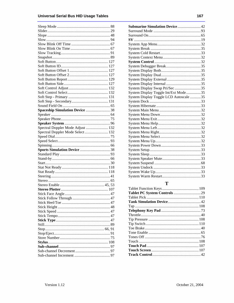
Universal Serial Bus HID Usage Tables 167
Version 1.12 October 21, 2004
Sleep Mode ....................................................... 88 Slider................................................................. 29 Slope ................................................................. 48 Slow .................................................................. 94 Slow Blink Off Time ........................................ 67 Slow Blink On Time ......................................... 67 Slow Tracking................................................... 91 Snapshot............................................................ 89 Soft Button...................................................... 127 Soft Button ID................................................. 127 Soft Button Offset 1 ........................................ 127 Soft Button Offset 2 ........................................ 127 Soft Button Report .......................................... 129 Soft Button Side.............................................. 127 Soft Control Adjust ......................................... 132 Soft Control Select.......................................... 132 Soft Step - Primary ......................................... 131 Soft Step - Secondary...................................... 131 Sound Field On ................................................. 65 Spaceship Simulation Device ......................... 38 Speaker ............................................................. 64 Speaker Phone................................................... 75 Speaker System ............................................... 96 Spectral Doppler Mode Adjust ....................... 132 Spectral Doppler Mode Select ........................ 132 Speed Dial......................................................... 75 Speed Select...................................................... 93 Spinning............................................................ 66 Sports Simulation Device ............................... 38 Standard Play .................................................... 93 Stand-by............................................................ 66 Start................................................................... 30 Stat Not Ready ................................................ 118 Stat Ready....................................................... 118 Steering ............................................................. 41 Stereo ................................................................ 65 Stereo Enable .............................................. 45, 53 Stereo Plotter................................................. 107 Stick Face Angle............................................... 47 Stick Follow Through ....................................... 47 Stick Heel/Toe .................................................. 47 Stick Height ...................................................... 48 Stick Speed ....................................................... 47 Stick Tempo...................................................... 47 Stick Type ........................................................ 47 Still.................................................................... 89 Stop............................................................. 66, 91 Stop/Eject.......................................................... 91 Store Number.................................................... 75 Stylus .............................................................. 108 Sub-channel ..................................................... 97 Sub-channel Decrement .................................... 97 Sub-channel Increment ..................................... 97
Submarine Simulation Device ........................42 Surround Mode .................................................93 Surround On......................................................65 SV .....................................................................19 System App Menu.............................................32 System Break ....................................................35 System Cold Restart..........................................33 System Context Menu.......................................32 System Control ................................................32 System Debugger Break....................................35 System Display Both.........................................35 System Display Dual.........................................35 System Display External ...................................35 System Display Internal ....................................35 System Display Swap Pri/Sec ...........................35 System Display Toggle Int/Ext Mode...............35 System Display Toggle LCD Autoscale ...........35 System Dock .....................................................33 System Hibernate ..............................................33 System Main Menu ...........................................32 System Menu Down..........................................32 System Menu Exit .............................................32 System Menu Help............................................32 System Menu Left .............................................32 System Menu Right...........................................32 System Menu Select..........................................32 System Menu Up...............................................32 System Power Down.........................................33 System Setup.....................................................33 System Sleep .....................................................33 System Speaker Mute........................................33 System Suspend ................................................68 System Undock .................................................33 System Wake Up...............................................33 System Warm Restart........................................33
T Tablet Function Keys ......................................109 Tablet PC System Controls ............................29 Tablet Pick ......................................................110 Tank Simulation Device..................................42 Tap ..................................................................108 Telephony Key Pad .........................................73 Throttle..............................................................40 Tip Pressure ....................................................108 Tip Switch.......................................................110 Toe Brake..........................................................40 Tone Enable ......................................................65 Tones Off ..........................................................76 Touch ..............................................................108 Touch Pad ......................................................107 Touch Screen .................................................107 Track Control ..................................................42
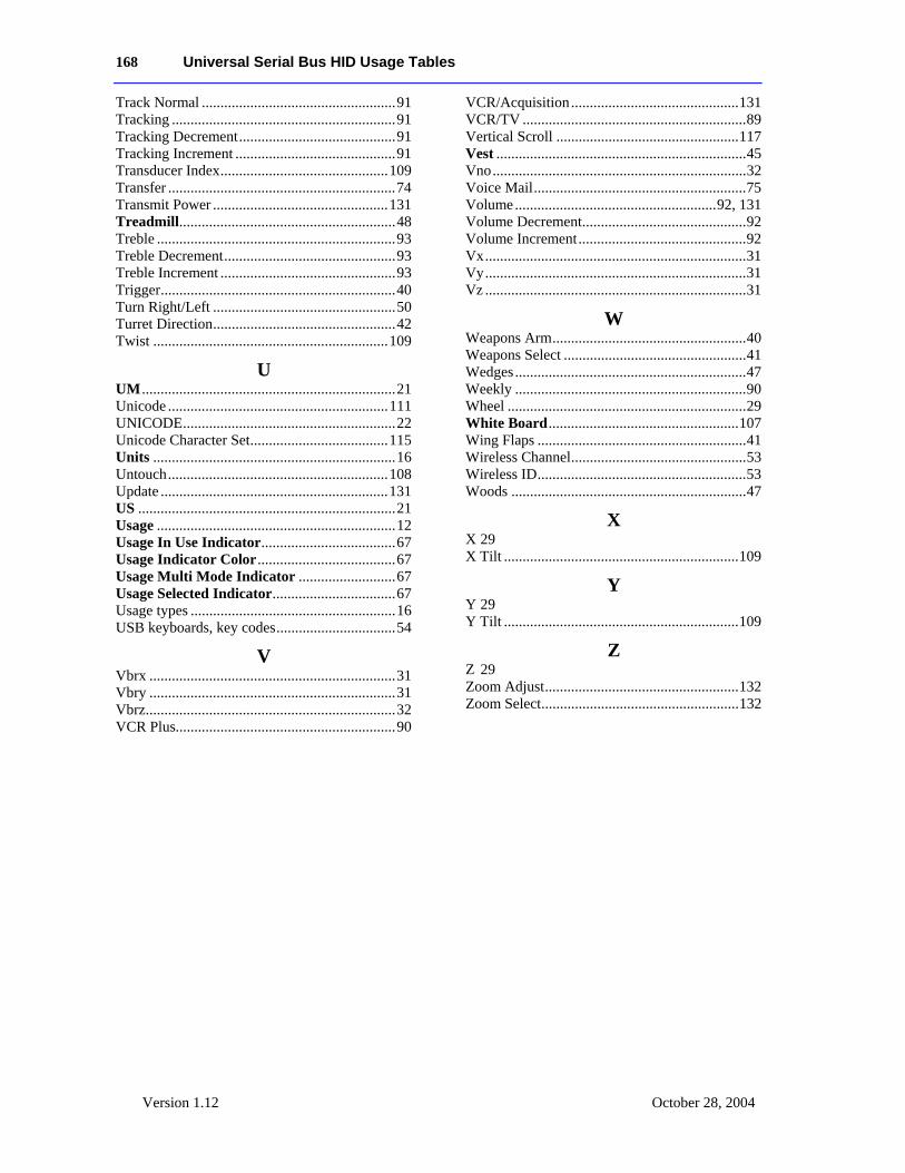
168 Universal Serial Bus HID Usage Tables
Version 1.12 October 28, 2004
Track Normal ....................................................91 Tracking ............................................................91 Tracking Decrement..........................................91 Tracking Increment ...........................................91 Transducer Index.............................................109 Transfer .............................................................74 Transmit Power ...............................................131 Treadmill..........................................................48 Treble ................................................................93 Treble Decrement..............................................93 Treble Increment ...............................................93 Trigger...............................................................40 Turn Right/Left .................................................50 Turret Direction.................................................42 Twist ...............................................................109
U UM ....................................................................21 Unicode ...........................................................111 UNICODE.........................................................22 Unicode Character Set.....................................115 Units .................................................................16 Untouch...........................................................108 Update .............................................................131 US .....................................................................21 Usage ................................................................12 Usage In Use Indicator....................................67 Usage Indicator Color.....................................67 Usage Multi Mode Indicator ..........................67 Usage Selected Indicator.................................67 Usage types .......................................................16 USB keyboards, key codes................................54
V Vbrx ..................................................................31 Vbry ..................................................................31 Vbrz...................................................................32 VCR Plus...........................................................90
VCR/Acquisition.............................................131 VCR/TV ............................................................89 Vertical Scroll .................................................117 Vest ...................................................................45 Vno....................................................................32 Voice Mail.........................................................75 Volume......................................................92, 131 Volume Decrement............................................92 Volume Increment.............................................92 Vx......................................................................31 Vy......................................................................31 Vz ......................................................................31
W Weapons Arm....................................................40 Weapons Select .................................................41 Wedges..............................................................47 Weekly ..............................................................90 Wheel ................................................................29 White Board...................................................107 Wing Flaps ........................................................41 Wireless Channel...............................................53 Wireless ID........................................................53 Woods ...............................................................47
X X 29 X Tilt ...............................................................109
Y Y 29 Y Tilt ...............................................................109
Z Z 29 Zoom Adjust....................................................132 Zoom Select.....................................................132