hetaless desiccant dryer
DESCRIPTION
Heatless Desiccant DryerTRANSCRIPT

THE NORGREN GUIDEto saving energy in compressed air systems

ENERGYSAVINGIN COMPRESSED AIR SYSTEMS
A typical 500 litres/sec (1,000 cfm) installation willconsume 46.000,00 € of electricity in a year. During itslifetime energy represents 75% of the total cost ofbuying and running a compressor. Numerousindependent studies confirm that industry wastesaround 30% of the compressed air it generates,equivalent to 13.800,00 € in our typical 500 litres/secinstallation. The aim of this guide is to help the enduser minimise wastage, by improving existing installedsystems. It will highlight key areas for savings, andoffer practical advice on an action plan.
For further information or advice contact Norgren at:for Belgium:[email protected] or call +32 (0)2 333 4452for Netherlands:[email protected] or call +31 (0)36 548 6839
COMPRESSED AIR IS OFTEN WRONGLY ASSUMEDTO BE A CHEAP OR EVEN ‘FREE’ SOURCE OF POWER.IT IS NOT.
LEAKAGE
Leakage is the major source of energy loss incompressed air systems. A typical plant may lose 20%of its compressed air through poorly connected pipejoints, fittings, couplings etc. Fixing the leaks andintroducing planned maintenance can producesubstantial savings.
MISUSE
The second major wastage of compressed air is to useit as a power source just because it is available. Theremay be better alternatives for moving, drying orcleaning products. Where compressed air is used,selecting correct equipment such as nozzles and useof control circuits can minimise wastage.
OVER PRESSURISATION
A considerable saving both in energy and equipmentlife can be made by using devices at the minimumpressure required for the application rather than fullline pressure. Simple use of pressure regulatorsoffers very fast payback.
PRESSURE DROP
Loss in pressure, due to blocked filter elements andundersized pipework, can mean pressure starvation atthe end of compressed air lines. The guide showsexamples of how to choose and maintain equipmentto minimise pressure drop in systems.
ENERGY AND SAFETY
Components fitted for safety reasons, such as presetregulators and shut off valves, can also help energysaving. This section reviews relevant parts of BS EN983 and other standards linking them to energyissues.
GENERATION
The correct selection of control equipment tomultiple compressor set ups, attention to inletcooling and after treatment of the compressed aircan realise good energy savings. Regular and correctmaintenance of compressors, filters and dryers isalso vital.
ACTION PLAN AND FURTHERINFORMATIONA simple checklist for action and sources of furtherinformation.
APPENDIX CHARTSENERGYSAVING

EXAMPLEENGINEERING
WORKSHOPAREA
The process of air preparation has been the core ofNorgren’s business for over 70 years. The guide reviews eachof the major opportunities for energy saving so that you cantake practical measures in your own plant.
Each section covers:• Where to look for savings• What to note or measure• How much does it cost?• What are the solutions?• How do we maintain good practice?
Throughout the guide you will find detailed examples of howto calculate the savings potential indicated by. These arebased around a model factoryEXAMPLEENGINEERING, which has many of the problemscommonly found in compressed air systems.
The factory has installed compressor capacity of 750 litres/sec(1,500 cfm), and an average demand of 500 l/s (1,000 cfm).It operates 24 hours per day, 7 days per week, for 50 weeksa year. Electricity costs 0,12 €/kWh. At 75% compressorutilisation, total cost is 90.160,00 € per year.The basis for most of the calculations is the “wastageformula”.This costs flow at:0,4 x hours x flow l/s x energy cost/kWh.
At EXAMPLEENGINEERING, typical leakage is 20% and equals100 l/s, which costs:0,4 x 8,400 x 100 x 0,12 € = 40.320,00 €.The calculation examples in this guide are based on onesection of the factory, the workshop area.The workshop operates for 2,500 hours per year, but the ringmain is pressurised all the time the factory is open. The totalsavings identified equal 30% of the air currently used by theworkshop area.
7 barring main
Filter 2”
Oil removalfilter 1”
2 x lathes + 2 blow guns
Filter 1” Filter 1”
Filter/reg1/4” setat 4 bar
HOW TO USE THIS GUIDE
2 x millers + 2 blow gunsGrinder rated 15 litres/sec. @ 4 barLaser cutter rated 10 litres/sec. @ 4 bar
4 x 2mm nozzels cleaning material
4 machines each with4 x sequence valves
Drilling machines10 drills rated 4
litres/sec. @ 4 bar10 2 blow guns
Test RigGauging andinstrumentation10 litres/sec.constant bleed1mm @ 4 bar
Leaks can be a significant source of wasted energy in anindustrial compressed air system.If compressed air were hydraulic fluid, leaks would be so visiblethat we would ensure their reduction. As it is we accept a lowlevel hiss in our work places as ‘part of the job’At a price which is roughly comparable to that of domestic gas,this attitude costs industry dearly.It is estimated that leaks cost UK industry 23.000.000 € perannum.
In addition to being a source of wasted energy, leaks can alsocontribute to other operating losses. Leaks cause pressure lossin systems, which can mean pressure is too low to the applicationleading to more reject product. Frequently the generation capacityis increased to compensate, rather than simply fixing the leaks.
WHERE TO FINDLEAKS MEASURING THELEAKAGE
LEAKS OCCUR EVERYWHERE!
PIPEWORKAgeing pipework is a prime source of leaks. Replace any corrodedpipework sections - for safety as well as energy saving.
FITTINGS, FLANGES AND MANIFOLDSLarge leaks are often found at connection points, both in the maindistribution system and in off takes. Sometimes when several snapconnectors are used together to form manifolds they can be asource of leakage due to worn connectors and poorly jointed pipework.
FLEXIBLE HOSES AND COUPLINGSLeaks can be caused by damage to hose due to abrasion bysurrounding objects, deterioration of the hose material and strain onthe joint because the hose is too long or too short.
OLD COMPONENTS NOT MAINTAINED - SEALS START TO LEAKCheck all pneumatic components eg old cylinders and regulators, forworn internal air seals which can cause large leaks.
CONDENSATE DRAINAGE VALVESLarge amounts of air can be lost when drain valves are stuck openor even left open intentionally. These can often be found in remoteparts of the system where condensate collects.
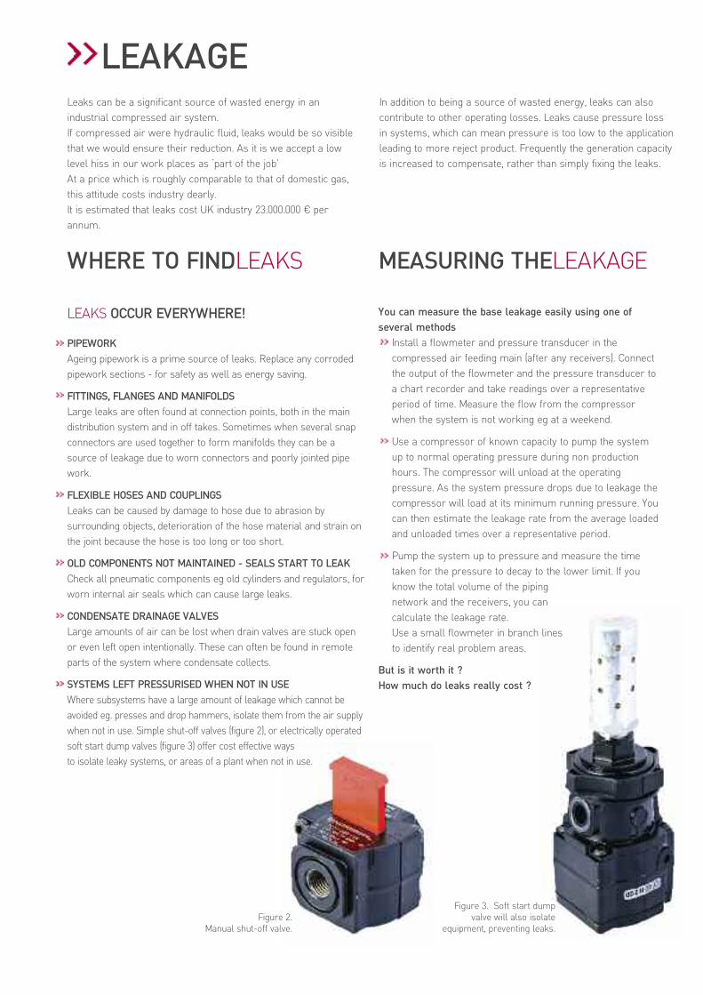
SYSTEMS LEFT PRESSURISED WHEN NOT IN USEWhere subsystems have a large amount of leakage which cannot beavoided eg. presses and drop hammers, isolate them from the air supplywhen not in use. Simple shut-off valves (figure 2), or electrically operatedsoft start dump valves (figure 3) offer cost effective waysto isolate leaky systems, or areas of a plant when not in use.
You can measure the base leakage easily using one ofseveral methods
Install a flowmeter and pressure transducer in thecompressed air feeding main (after any receivers). Connectthe output of the flowmeter and the pressure transducer toa chart recorder and take readings over a representativeperiod of time. Measure the flow from the compressorwhen the system is not working eg at a weekend.
Use a compressor of known capacity to pump the systemup to normal operating pressure during non productionhours. The compressor will unload at the operatingpressure. As the system pressure drops due to leakage thecompressor will load at its minimum running pressure. Youcan then estimate the leakage rate from the average loadedand unloaded times over a representative period.
Pump the system up to pressure and measure the timetaken for the pressure to decay to the lower limit. If youknow the total volume of the pipingnetwork and the receivers, you cancalculate the leakage rate.Use a small flowmeter in branch linesto identify real problem areas.
But is it worth it ?How much do leaks really cost ?
Figure 3. Soft start dumpvalve will also isolate
equipment, preventing leaks.Figure 2.
Manual shut-off valve.
LEAKAGE

WHAT DOES ITCOST?
A single leak from a hole diameter 2mm can cost 690,00 € peryear, in our workshop example. Use orifice flow chart(figure 19 in the appendix chart section) to calculate leakage atdifferent bore sizes and pressures.
REDUCINGLEAKAGE
Set targets for leakage reduction. Publicise how much moneythe leakage is costing the organisation and how much youintend to save. Implement an ongoing maintenanceprogramme - have ‘leak’ tags available and encourage theiruse.Carry out a survey of the compressed air system. Inspectduring quiet hours. Listen for pipework or tool leaks andexamine hoses and couplings. Spray ‘spotleak’ on pipe jointsand watch for bubbles.The average leak will take around half a man hour to fix, andoffer very quick payback.Fixing the leaks will clearly save significant amounts of money,but how do we make sure they stay fixed?Implementing a site-wide awareness programme leads to longterm savings on a big scale.Dividing the site into areas, fitting air consumption meters andcharging each area for its air usage will soon focus theattention of energy users. Targets can then easily be set toreduce energy loss due to leaks.
Bore Size
2
1
LEAKAGEAfter surveying the workshop area a number of leakswere found:
1 x 2mm leak @ 4 barand 11 x 1mm leak @ 7 bar
Using the orifice flow table, that equates to4,8 l/s and 11 x 1,2 l/s
Total leaks = 18 l/s
POTENTIAL FOR SAVING
0,4 x 8,400* x 18 x 0,12 € = 7.257,60 €* assumes system stays pressurised for 24 hours per day,
50 weeks per year.
COST OF SOLUTION
Estimate 1/2 a man hour to fix each leak@ 38,00 € per hour = 228,00 €
Savings Expense Nett saving7.257,60 €€ 228,00 € 7.029,60 €€
Figure 4. Leakage rate for different hole diameters.
Figure 5. Leakage can be from any joint and is easily shown by spotleak.
ENERGYSAVING

The second major wastage of compressed air is to use it as apower source just because it is available.Some examples of this are inefficiently creating vacuum,ejecting faulty products and removing water/dirt/powder fromproducts. There may be better alternatives for theseapplications. If compressed air is chosen the correctequipment and control must be employed to keep usage to aminimum.
WHERE TO FINDMISUSE
In an existing plant new misuses can often be seen by anincrease in air demand and/or compressor running hours. Toidentify existing misuses all areas of the plant need to besurveyed, asking the question - is this an effective use of air?
COSTING THE MISUSE
Where a process has air passing to atmosphere, such asrejection of under weight or faulty product in a canning process,a flowmeter can be installed in the line to measure the air usage.Then by using the wastage formula the cost of this process canbe found.
RECOMMENDED PRACTICE
Another way to calculate costs is to use the exit orifice or nozzlediameter and the applied pressure to calculate the flow (seetable, figure 19 orifice flow, appendix chart section).Where nozzles must be used, for example blowing loose flour offloaves of bread (fig 6), then ensure that the distance betweenthe exit nozzle and the product is as short as possible as this willallow the supply pressure to be reduced. The nozzle should bedirected only at the area needed giving a cone (circular area) or fanspray (long narrow band) etc. Where a very long narrow areaneeds to be covered use nozzles in parallel to produce a curtainreducing the distance to the furthest point. Ensure the mains feedline to a number of nozzles is of sufficient diameter so as not torestrict the outlet flow.Air saver nozzles entrain and accelerate air within theirmechanism to produce the desired outputs with reduced supplypressures, giving savings of up to a twenty fold reduction incompressed air usage (fig 7).
Finally where such solutions must be used ensure control valves andsensors are fitted to the system, so that flow only occurs when theproduct is at the application point, with no flow during the gapsbetween product on the conveyor, or at work breaks etc. In somecases the solution is not to use compressed air. Dedicated air blowersor vacuum pumps may well prove more cost effective.All such solutions can be costed and compared to the airusage/wastage and in almost every case savings can be made.Once misuse has been determined within a plant, ensure thatwhen new processes are installed due consideration is given tothe power source and controls are in place.
MISUSEMaterial is cleaned prior to being cut by the laserusing 4 x 2 mm at line pressure.4 x 2 mm nozzle presets 4 x 4,8 l/s at 7 bar
4 x 1,81 l/s at 2 bar
Using the orifice flow table, figure 20.So a reduction in pressure to 2 bar will give a flowsaving of 11,96 l/s.
POTENTIAL FOR SAVING
0,4 x 8,400* x 11,96 x 0,12 € = 4.822,27 €* assumes no isolation valves and system is continually pressurised.
COST OF SOLUTION:
Fit one pressure regulator = 41,50 €Estimate 1/2 a man hour @ 38,00 € per hour= 19,00 €Total 60,50 €
Savings Expense Nett saving4.822,27 €€ 60,50 € 4.761,77 €€
Figure 7. Blow gun with air saver nozzle.
Figure 6.Example of poor practice. Nozzle should be closer to the bread andof an air saver design. A control circuit is needed to stop air whenno bread is under the nozzles. Consider local filtration andmembrane dryer for high quality dry air.
MISUSE

IDENTIFYINGOVERPRESSURISATIONThe absence of pressure regulators in a system indicates thatequipment is being used at excessive pressures. Savings can berealised in many areas, including air tools, control valves,clamping cylinders and on the return stroke of large doubleacting cylinders.Where pressure regulators are present but outlet pressure isthe same as the inlet, this often indicates poor lubrication withextra pressure being applied to overcome the friction slowingdown the process. This is costly in extra wear and energy.
CALCULATING THE COSTS
All air tools are rated for their flow and optimum pressure. The air wastage can be calculated by using the pressure ratio(absolute), and then multiplying by the rated air flow i.e.consumption at 3 bar is 8 l/s at 7 bar this will be
(7 + 1) x 8 = 16 l/s(3 + 1)
This can then be substituted into the annual wastage formula tocalculate savings.
Double acting cylinders usually only do work on the out stroke(work stroke). When no work is being done or longer reset timesare possible, the return stroke can be at a lower pressure.Where large bore, long stroke or multiple cylinder systems exist,considerable air savings can be made. Using a regulator toreduce return stroke pressure can be a fast payback solution.Consumption with reduced pressure return stroke for doubleacting cylinder can be measured using the formula
Air saving = 0,7854 x d2 x L (P1 - P2) x 10-6
T x 60
d = cylinder diameter (mm)
L = stroke length (mm)
T = time for 1 stroke (sec)
P1 = applied pressure (bar) - outstroke
P2 = applied pressure (bar) - return stroke
Valves have a rated conductance C in litres/sec per bar absolute.Any flow saving is calculated by simply reducing the appliedpressure. It is important to note the valve operating duration (i.e.time that flow occurs) to ensure that the correct flow saving isarrived at. Usually this figure is small but for multiple valveinstallations and/or rapidly cycling valves with long pipe runs thetotal saving can be significant.Once over pressure examples have been identified within afactory, ensure that all new plant, processes and equipment areexamined for optimum operating conditions and pressure controlequipment prior to installation. This should be reflected inincreased tool life as well as reduced energy costs.
Figure 8. Set the pressure to the air tool at ratedsetting, not mains pressure.
10 to 9 bar 5 bar
OVER PRESSURISATION10 air tools rated @ 4 bar.These drills are all supplied with 7 bar line pressure, and each isused on average for around 1,000 hours per year.The air consumption of each drill at 4 bar is 15 l/s. therefore at 7 bar each tool will be consuming:8 x 15 = 24 l/s5
So by using a lower pressure there is a potentialsaving of 9 l/s per tool.Over the total 2,500 hours of annual usage, theaverage flow saving = 1,000 x 9 = 3.6 l/s
2,500
POTENTIAL FOR SAVING PER TOOL0,4x2500x3,6x0,12 € = 432,00 €For 10 tools that will be = 4.320,00 €
COST OF SOLUTION:
Fit one pressure regulator per tool = 59,80 € x 10 = 598,00 €
1/2 man hour for fitting @ 38 € per hour = 19,00 € x10 = 190,00 €
Total 788,00 €* calculations need to be done with absolute pressures – i.e.
1 bar higher than reading
Savings Expense Nett saving4.320,00 €€ 788,00 € 3.532,00 €€
OVERPRESSURISATIONMany systems run at full line pressure with the only controlbeing the pressure switch on the compressor.Every item of pneumatic equipment has an optimum operatingpressure and flow. Usage outside of these conditions willshorten the equipment life due to increased loading and wear,and will increase the running costs. A device running at 7 barwill consume twice as much air as it would at 3 bar.

Pressure drop can be defined as ‘the loss in a system ofpower available to do work’. In practice it is shown by lowpressure in parts of the system. It is often compensated forby increasing generation pressure or turning up regulators.The potential energy generated by compressing the air isdissipated through friction and heat losses as it is pushedthrough all the components of the system. We need therefore to design and maintain systems tominimise the amount of pressure drop. Every 1 bar ofunnecessary pressure drop leads to an increase of 7% ingenerating costs. This means around 4.025 € per annum toour typical factory.The two main areas where pressure drop occurs arepipework and filtration.
PIPEWORKPressure drop occurs in pipework mainly as a result of frictionof the air molecules with the surface of the pipe. If the pipe istoo small for the volume of flow the velocity of the air will bevery high and there will be a big loss in power.Energy is also lost when there is a change in flow direction i.e.elbows, junctions and shut off valves. Simple pipe systems willminimise pressure drop (fig 9).
How to calculate pressure drop in pipework:Method 1• Measure supply pressure.• Measure the pressure at furthest point from supply.• The difference is the system pressure drop.Method 2• Estimate the flow usage - eg. calculate the swept volume of
working cylinders.• Note the supply pressure and the diameter of the pipe.• Use published normagraphs to arrive at the pressure drop.Method 3• Use a small flowmeter to measure the flow.• Note the supply pressure and the diameter of the pipe.• Use figure 22 in tables to see whether flow is within
recommended range.
RECOMMENDATIONSDon’t over flow the pipework. Keep velocity below 6 m/s in mains.Simplify the pipework. Avoid elbows as a 90 degree elbow isequivalent to 1.6 m of straight pipe.Fit ‘low resistance’ valves; a full flow ball valve equates to 0.4 mof pipe, less than half the resistance of a gate valve. Figure 21 intables shows examples.
FILTRATIONFiltration is an essential part of the conditioning in acompressed air system. If not protected from water, particlesand degraded compressor oils, machines will quicklybreakdown.To keep pressure drop as small as possible:
Look for the right size filter unit
As with pipework if the filter unit is too small for the flowrequired then it will give a higher pressure drop. When new ageneral purpose filter should give no more than 0,1 barpressure drop. Fitting a smaller filter is a false economy, as itwill give higher initial pressure drop and also block morequickly because the surface area of the element is smaller (fig 10).
PRESSUREDROP
Figure 9. Example of poor pipework on a production test rig. Figure 10. Selecting the right size filter isimportant.

Look for the right level of filtration
A very fine filter will have a greater resistance to flow than acoarse filter. Most air tools for example will only requirefiltration to around 40 micron. It makes sense therefore not touse a 5 micron or even a 0,01 micron filter in this application (fig 11).Where applications needing higher grade filtration exist, placethe higher grade filters as close to the application as possible.This ensures that the size of filter determined by the flow is assmall as possible. Do not filter the whole of the air line orbranch line to this standard, since this will increase the flowrequirement, increasing the size of the filter, its purchase price,replacement element price and incur extra pressure loss for thewhole of the system downstream of it.
Look for dirty filter elements- check pressure drop indicators
After some time in service, particles will be trapped within thefilter media causing the element to become blocked. This meanspressure is lost at the application. What usually happens at thisstage is that the pressure is increased to compensate by turningup a regulator. Increasing the pressure increases the costs.An extra 0,35 bar of pressure drop in a line can cost as muchas 460,00 € per year.Fitting pressure drop indicators - simple pneumatic or electrical(fig 13) can indicate immediately when pressure drop isincreasing. Changing the elements at this point meanssignificant energy saving.
It is good practice to change the filter elements at regularintervals. This will ensure that energy wastage is kept to aminimum and that correct air quality is delivered (fig 12).Any new plant should be installed with the right level of airquality in mind - instrument quality only where the applicationdemands it.Delivering very dry high quality air to all areas of the site iscostly and should be avoided.
PRESSUREDROPA 2" filter flowing 400 l/s @ 7 barwhen new, pressure drop = 0,15 barin 2 years this could increase to 0,4 barThis extra 0,25 bar creates an extra power demand of1,8 Kwh.
POTENTIAL FOR SAVING
For 2,500 hours total extra power =1,8 Kwh x 2,500 @ 0,12 € per Kwh extra cost = 540,00 €
COST OF SOLUTION:
Replace filter element = 160,18 €1/2 a man hour labour @ 38,00 € per hour = 19,00 €Total 179,18 €
Savings Expense Nett saving540,00 €€ 179,18 € 360,82 €€
Figure 11. The effect of filter grade onpressure drop.
Figure 12. Cost saving through regularelement changes.Figure 13. Filters with integral pressure drop indication.

How can Safety be an Energy Issue ?In compressed air systems components fitted for valid safety reasons have a cost. However there are some that offera payback resulting from the benefits gained in energy savings.There are several documents that deal with safety ofcompressed air systems and pneumatic components. Some are international standards whilst others though nothaving legal status, offer best practice guidance from safetyorganisations and leading fluid power trade organisations.
BS EN 983 - LEAKS
‘Leaks (internal or external) shall not cause a hazard’.In systems where air pressure is used to maintain a load, suchas in a press, braking or clamping application, a leak couldpotentially constitute a hazard.
BS EN 983 - FILTRATION
‘Filter condition monitoring. If deterioration of filter performancecould lead to a hazardous situation, clear indication should begiven’.A blocked filter, leading to reduced downstream pressure couldhave a similar effect to a leak in systems where the pressure isused to maintain loads.Pressure drop indicators will show when the filter is blockingand needs changing. This also minimises energy costs bykeeping pressure drop to an acceptable level.
BS EN 983 - TAMPER RESISTANT DEVICES
‘Pressure and flow control devices or their enclosures shall befitted with tamper resistant devices where an unauthorisedalteration to pressure or flow can cause a hazard.’Frequently, pressure is increased to machines or systems in thehope that the increase will speed up the process. Usuallythere are other factors within the system which will limit thisand increasing the pressure will only increase the airconsumption.In some cases, increasing the pressure can be unsafe such aswhen using pneumatic clamps. The force generated iscalculated to clamp the component; any increase in that forcemay result in crushing of the component which may shatter orexplode.Simple tamper evident covers, which can be padlocked, can befitted to regulators to ensure systems remain safe (fig14).Lockable shut off valves prevent someone accidentally turningoff the air to a system, or turning on the air while a machine isbeing maintained creating a potential hazard.
BS EN 983 - SOFT START DUMP VALVES
Machines should be designed so that at start up any movingcomponents reach their working position in a safe manner.There must also be a safe way of releasing the system air veryquickly when signalled.Combined soft start dump valves achieve both these functions inone unit. They also have the added benefit that the signal can belinked to one power down operation which will isolate themachine when not in use. This means any leaks or constantbleed devices will not drain the main system.
HSG 39 - CORRECT USE OF BLOW GUNS
‘Blow guns, consisting simply of a reduced orifice in direct linewith the supply hose, can be extremely dangerous, unlesspreceded by a pre-set tamperproof pressure regulator set at areduced pressure from the normal 80 psi air line supply.’Blow guns are commonplace throughout industry and whilst most people are familiar with their use, the very real hazards they present are often not appreciated. As an example a pressure of 0,4 bar can penetrate human skin with possible fatal results if air gets into the bloodstream.Many blow guns are operated at full line pressure and can even be ‘home made’ i.e. short pieces of copper tube with diameters up to 6 mm. This situation is clearly dangerous. A secondary concern is the sheer volume of air that is wasted.Good practice would be a blowgun with built in side
ENERGY&SAFETY
Figure 14. Use of a lockable tamper evident cover on a filter/regulator.
Figure 15. Pre-set tamper proof regulator for Blowguns.

vents to prevent pressure build up if the nozzle becomesblocked, preceded by a small preset non adjustable regulator(see figure 15).If reduced pressure presents problems with an operation suchas cleaning swarf from a component, then blow guns withefficient nozzles can be used to entrain some atmospheric air.This equipment will provide a safe working situation with theadded benefit that it will pay for itself very quickly in reducing airusage.
BS 6005 - 1997 SAFETY OF POLYCARBONATE BOWLS
Polycarbonate is commonly used for bowls on filters, filter-regulators and lubricators, offering clear visibility of bowlcontents. However, in an industrial environment itneeds to be treated with some care. The standards says:A.4.1.2 ‘Bowls which on visual inspection show signs ofmechanical damage, cracking, or hazing should bereplaced’.A.4.1.3 ‘Bowls which have been contaminated with paint shouldalso be replaced; they should not be cleaned’.A.4.1.4 ‘All bowls which have been in service for 10 years shouldbe replaced, even though they may appear acceptable by thevisual inspection mentioned in A.4.1.2’Whilst changing bowls which have any of the above problemswill not directly save energy, it should be included in amaintenance plan which also checks the condition of filterelements and drains to reduce pressure drop and leaks.
Filters are notorious for being badly maintained and it isimportant to raise awareness of the safety implications ofneglect of these units (fig 16).
PUWER - ISOLATION FROM AIR SUPPLY
Regulation 19 ‘Every employer shall ensure that whereappropriate work equipment is provided with suitable means toisolate it from its sources of energy’.A variety of valves are available to help meet this requirement:• ball valves (fig 17)• shut off valves included in FRL units• electrical operated control valves• pneumatically operated control valvesUse of these has the added benefit that any leakage in thesystem downstream will not be continually draining the mainsair supply.
AIR FUSE
The use of air fuses can also have an effect on energy saving.The device is designed to prevent pneumatic hoses whippingaround, exhausting high pressure air in the event of a hosefracture. The fuse reduces the flow to atmosphere, so that onlya very small amount of air escapes, compared to full line failureflow. Danger of injury from the hose is eliminated and energywastage is minimised.In situations where isolating valves and air fuses do not exist, itwould be necessary to bleed down the system, wasting all thecompressed air before the hose failure could be repaired.
ENERGY&SAFETY18 blow guns with 4 mm hole, supplied with 7 barline pressure.Blow guns should be regulated to a lower pressureusing the orifice flow table:Flow through 4 mm @ 7 bar = 19 l/sFlow through 4 mm @ 2 bar = 7 l/sPotential flow saving per gun = 12 l/sGun is used for 300 hours per year(around 10 minutes in every hour)Average saving per year = 300 x 12 = 1,4 l/s
2,500Total for 18 blow guns = 25 l/s
POTENTIAL FOR SAVING
0,4 x 2,500 x 25 x 0,12 € = 3.000,00 €
COST OF SOLUTION:
18 preset regulators = 1.038,42 €1/2 man hour to fit each = 342,00 €Total 1.380,42 €
Savings Expense Nett saving3.000,00 €€ 1.380,42 € 1.619,58 €€
Figure 16. Typically aged units still working on a CNC machine.
Figure 17. Lockable shut-off valve

At best only 5% of the input energy to an air compressorremains in the air after it is compressed. This is due to the heatrejected by the compressor in its cooling systems.Most compressor locations will contain the compressor, thetreatment system and the control system. Each element of thecompressor station, the installation and its maintenance has aneffect on energy efficiency.
COMPRESSOR SIZE AND CONFIGURATIONThe size and configuration of compressor is important in termsof energy efficiency.Depending on the demand pattern, it is normal to have thelargest and most efficient machine on line to handle the baseload and other machines coming on and off line to meetchanges in demand.Most modern installations use rotary compressors of the oilinjected vane and screw types. When higher quality and largervolumes of air are needed, oil free screw or centrifugalmachines can be used and these usually have betterefficiencies. (See figure 20)Although not so popular for new applications, unless they arefor special gases or high pressure, there are many pistonmachines still in operation. These machines particularly in thelarger sizes have excellent efficiency and part load control.Variable speed drives are becoming quite common as are twostage oil injected machines.
INSTALLATIONCooling is most important with all compressors. The inlet airshould be as cool as possible, ideally taken from a shadedoutside location. In general a 4°C reduction in inlet temperaturewill give an improvement of 1% in efficiency.A simple check on a compressor’s health is to measure thedifferences in temperature between the cooling medium and thedischarge air from the aftercooler.For air-cooled compressors this should not exceed 15°C.For water-cooled compressors this should not exceed 10°C.If greater temperature differences are found the machines’efficiency will be lower than design. The cooling systems shouldbe improved.Make sure all the feeding mains are correctly designed withflow velocities not greater than 6 metres per second. Use swepttees and long radius elbows at all pipe junctions.Use electronic level sensing traps on all condensate collectionpoints and ensure condensate recovery conformsto the regulations.
HEAT RECOVERYUse the waste heat of compression for space heating, domesticwater heating or process water. Large savings can be achievedby doing this.
MAINTENANCEThe way compressors are looked after in the field has a majorimpact on generation efficiency. Machines should always bemaintained strictly in accordance with the manufacturersinstruction book.It is a false economy to run rotary vane and screw units past themanufacturer’s recommended compression element lifecycle. Typically this is 24,000 hours with oil-injected machinesand 40,000 hours for oil free machines.Regularly inspect the intercooler pressure on two stage pistonand screw compressor. This should be around 2 to 2,5 barwhen the final discharge pressure is 7 bar. Any deviation showsstage imbalance giving poor efficiency. Similarly check thepressure drop across the oil separator system.If the maintenance of your compressor is conducted by a thirdparty firm, make sure you use a manufacturer’s accreditedagent. Only use genuine spare parts; items which are not of theoriginal design or poorly refurbished will have a serious effecton energy efficiency. A small apparent saving in these areas cangive a false economy in the long term.
CONTROLWhere a number of compressors, possibly of different types andsizes are used to meet varying air demands, then a controlsystem should be employed. This will optimise the number andmix of compressors to meet the demand, giving close pressurecontrol with the most energy efficient mix of machines.
TREATMENTOnly treat the air to the minimum standard required. Refrigeratedair dryers giving +3°C dewpoint and filters add 3% to the energycost. Desiccant air dryers and filters giving -40°C dewpoint addbetween 8 and 15% to the running costs.Use desiccant or membrane dryers at the point of use to saveenergy. Use dewpoint sensing controls with desiccant dryers.Keep treatment system pressure losses to 0,5 bar. Size filtersfor the maximum flow, do not allow reduced flange sizes.Maintain filters regularly. Figure 23 in tables show the relativecosts of treatment.
OPERATING PRESSUREEstablish the minimum acceptable pressure at the point of use andensure the piping network is designed such that the pressure dropwith the system on full load does not exceed 0,5 bar.If possible, reduce the generation pressure. A reduction of 1 barcan save 7% of the generation cost. Reduced pressure alsoreduces the unregulated air demand of the plant. A reductionfrom 8 bar to 7 bar will reduce the unregulated demand byaround 12%.
GENERATION
Typical large compressor house with multiple compressors
ETSU PUBLICATIONS
ETSU the energy efficiency branch ofthe Department of Environment Transport and Regions, offer a range offree publications on all aspects of energy saving. For compressed airinformation refer to:
Good Practice Guides
216 Energy Saving in the Filtration and Drying of Compressed Air
238 Heat Recovery from Air Compressors
241 Energy Savings in the Selection, Control and Maintenance ofAir Compressors
Good Practice case studies
Carbon Trust 0800 085 2005.
Energy consumption guides
ECG040 Compressing Air Costs:- Generation
ECG041 Compressing Air Costs:- Leakage
ECG042 Compressing Air Costs:- Treatment
OTHER PUBLICATIONS
HSG 39 Compressed Air Safety
BS 6005 1997 Specifications for Moulded TransparentPolycarbonate Bowls used in Compressed AirFilters and Lubricators
PUWER Provision and Use of Work Equipment Regulations1998
BS EN983 - 1996 Safety of machinery -safety requirements for fluid power systems and theircomponents - pneumaticsA European Norm standard that supports the ‘essentialhealth and safety requirements of theEuropean Machinery Directive. It identifies hazards whichaffect the safety of systems and their components when putto their intended use. It is not a manufacturing standard sodoes not give guidance in the manufacturing of pneumaticcomponents.
ACTIONPLAN FURTHER SOURCES OFINFORMATION» Measure System Flow Demand:
Survey Factory In 3 Areas:• compressor house• ring main• bays/point of use
Focus In Each Area On:• leaks• misuse• over pressure• pressure drop• safety issues
then locally measure usage if possible
Having Identified Areas for Savings:cost out corrective action and• payback• implement• check/flow pressure drop to validate• measure
Use Revised Flow Figures to ModifyControl System for Compressors wherenecessary
Implement Ongoing PreventiveMaintenance and Periodic Re-audit (LeaksCome Back)
www.envirowise.gov.ukwww.energy-efficiency.gov.uk
Clean Compressed AirNorgren’s Guide to Effective Air Preparation

APPENDIXCHARTSFigure 19.
ORIFICE FLOW CHART
Orifice Size (hole) litres/sec - ANR (dm3/s)
(mm) 2 bar 4 bar 6 bar 7 bar 8 bar
0.2 0.02 0.03 0.04 0.05 0.06
0.3 0.04 0.05 0.10 0.11 0.12
0.5 0.11 0.19 0.26 0.30 0.39
1.0 0.45 0.73 1.05 1.20 1.35
1.5 1.02 1.70 2.37 2.69 3.05
2.0 1.81 3.05 4.20 4.80 5.40
3.0 4.00 6.77 9.46 10.81 12.16
4.0 7.27 12.04 16.82 19.16 21.67
5.0 11.35 18.83 26.32 30.00 33.82
6.0 16.34 27.16 37.82 43.32 48.65
8.0 29.16 48.15 67.30 76.90 86.50
10.0 43.32 75.30 105.10 120.10 135.10
15.0 102.10 169.90 236.60 269.90 304.00
Figure 20.
COMPRESSOR EFFICIENCIES
Configuration Capacity Specific Power Part Loadlitres/sec Kwe/50 l/s Efficiency
2–25 24 Good
Lubricated piston 25–250 20 Good
250–1,000 17 Excellent
2–25 26 Good
Oil-free piston 25–250 22 Good
250–1,000 19 Excellent
Oil injected 2–25 24 Poor
rotary vane 25–250 22 Fairand screw 250–1,000 19 Fair to good
25–250 20.5 GoodOil-free toothed 250–1000 18 Goodrotor and screw
1,000–2,000 18 Good
250–1,000 21 Good
Oil-free centrifugal 1,000–2,000 18 Excellent
Above 2,000 17 Excellent

Figure 21.
FRICTION LOSS IN PIPE FITTINGSIN TERMS OF EQUIVALENT METRES OF STRAIGHT PIPE
8mm 10mm 15mm 20mm 25mm 32mm 40mm 50mm
Tee (straight through) 0,15 0,15 0,21 0,34 0,46 0,55 0,67 0,92
Tee (side outlet) 0,76 0,76 1,01 1,28 1,62 2,14 2,47 3,18
90° elbow 0,43 0,43 0,52 0,64 0,79 1,07 1,25 1,59
45° Elbow 0,15 0,15 0,24 0,30 0,38 0,49 0,58 0,73
Ball valve* 0,01 0,03 0,09 0,12 0,15 0,22 — —
* Self exhausting – full open
Figure 22.
MAXIMUM RECOMMENDED FLOW* THROUGH ISO 65 MEDIUM SERIES STEEL PIPE.
Applied Nominal Standard Pipe Size (Nominal Bore) – mmGauge 6 8 10 15 20 25 32 40 50 65 80Pressure Approximate Pipe Connection – inchbar 1/8 1/4 3/8 1/2 3/4 1 11/4 11/2 2 21/2 3
0,4 0.3 0.6 1.4 2.6 4 7 15 25 45 69 120
1,0 0.5 1.2 2.8 4.9 7 14 28 45 80 130 230
1,6 0.8 1.7 3.8 7.1 11 20 40 60 120 185 330
2,5 1.1 2.5 5.5 10.2 15 28 57 85 170 265 470
4,0 1.7 3.7 8.3 15.4 23 44 89 135 260 410 725
6,3 2.5 5.7 12.6 23.4 35 65 133 200 390 620 14085
8,0 3.1 7.1 15.8 29.3 44 83 168 255 490 780 14375
10,0 3.9 8.8 19.5 36.2 54 102 208 315 605 965 14695
*Air flow rates in dm3/s free air at standard atmospheric pressure of 1,013 mbar.General notesThe flow values are based on a pressure drop (DP) as follows:10% of applied pressure per 30 metres of pipe 6 – 15 mm nominal bore inclusive5% of applied pressure per 30 metres of pipe 20 – 80 mm nominal bore inclusive
Figure 23.
ADDITIONAL COSTS FOR TREATING COMPRESSED AIR
Pressure Dew-point Dryer Type Filtration Added Cost Over Initial°C Generation Cost
Typical 10 Membrane Pre 10 - 15% Low
3 Refrigerated General purpose 3% Medium
–40 Heatless desiccant Pre and after 8 - 15% High
–40 Heated desiccant Pre and after 10 - 15% High
–70 Heatless desiccant Pre and after 15 - 21% High

a subsidiary of IMI plc
The Roundel,’Norgren’ and ‘IMI’are registered trade marks© Norgren Limited 2010.Due to our policy of continuousdevelopment, Norgren reserve theright to change specificationswithout prior notice.
z7132 en/07/10
AUSTRALIATel: +61 3 9213 0800Fax: +61 3 9213 [email protected]
AUSTRIATel: +43 22 36 63 520Fax: +43 22 36 63 520 [email protected]
BELGIUM & LUXEMBURGTel: +32 2 333 44 11Fax: +32 2 333 44 [email protected]
BRAZILTel: +55 11 5698 4000Fax: +55 11 5698 [email protected]
CANADATel: +1 303 794 2611Fax: +1 303 795 [email protected]
CHINATel: +86 21 2416 1800Fax: +86 21 2416 [email protected]
CROATIATel: +386 4 5317550Fax: +386 (64) [email protected]
CZECH REPUBLIC & SLOVAKIATel: +420 465 612 879Fax: +420 465 612 [email protected]
DENMARKTel: +45 44 91 41 66Fax: +45 44 91 15 [email protected]
FINLANDTel: +358 95 712 140Fax: +358 95 712 [email protected]
FRANCETel: +33 1 60 04 95 95Fax: +33 1 60 43 18 [email protected]
GERMANYTel: +49 2802 49–0Fax: +49 2802 [email protected]
HONG KONGTel: +852 2492 7608Fax: +852 2498 [email protected]
HUNGARYTel: +36 1 284 9000Fax: +36 1 284 [email protected]
INDIATel: +91-120-4089500Fax: [email protected]
IRELANDTel: +353 1 8300 288Fax: +353 1 8300 [email protected]
ITALYTel: +39 039 60 631Fax: +39 039 60 63 [email protected]
JAPANTel: +81 6 6876 8913Fax: +81 6 6876 [email protected]
MALAYSIATel: +60 3 5121 9255Fax: +60 3 5121 [email protected]
MEXICOTel: +52 55 1500 64 00Fax: +52 55 1500 64 [email protected]
NETHERLANDSTel: +31 (0)36 548 6828Fax: +31 (0)36 548 [email protected]
NEW ZEALANDTel: +64 9 579 0189Fax: +64 9 526 [email protected]
NORWAYTel: +47 22 90 80 80Fax: +47 22 90 80 [email protected]
POLANDTel: +48 22 518 9530Fax: +48 22 518 [email protected]
ROMANIATel: +40 31 425 17 06Fax: +40 31 425 17 [email protected]
RUSSIATel: +7 499 729 56 09Fax: +7 499 729 57 [email protected]
SINGAPORETel: +65 6862 1811Fax: +65 6862 [email protected]
SLOVENIATel: +386 4 531 7550Fax: +386 4 531 [email protected]
SPAINTel: +34 93 748 9800Fax: +34 93 783 [email protected]
SWEDENTel: +46 40 59 51 00Fax: +46 40 49 50 [email protected]
SWITZERLANDTel: +41 71 973 82 00Fax: +41 71 973 82 [email protected]
TAIWANTel: +886 33162673Fax: +886 [email protected]
THAILANDTel: +66 2750 3598/99Fax: +66 2750 [email protected]
UKTel: +44 1543 265 000Fax: +44 1543 265 [email protected]
USATel: +1 303 794 2611Fax: +1 303 798 [email protected]
Supported by distributors worldwide
www.norgren.com