helicopter with gps
DESCRIPTION
Sir, this is one of the journal i found online. But i don't really understand the contents.TRANSCRIPT
ACCURACY ENHANCEMENT OF UNMANNED HELICOPTER POSITIONING WITH LOW COST SYSTEM
U. Coppa a, A. Guarnieri b, F. Pirotti b, A. Vettore b
aVesuvius Observatory – National Institute of Geophysics and Volcanology - Naples, Italy, [email protected] bCIRGEO – Interdepartment Research Center for Geomatics, University of Padova - Italy, [email protected]
Commission I, Working Group V/1
KEY WORDS: UAV, Model helicopter, Kalman filter, MEMS, Autopilot ABSTRACT: In the last years UAV (Unmanned Aerial Vehicle) systems are become very actractive for various commercial, industrial, public, scientific and military operations. The tasks include pipeline inspection, dam surveillance, photogrammetric survey, infrastructure maintenance, inspection of flooded areas, fire fighting, terrain monitoring, volcano observations and so on. The impressive flying capabilities provided by UAVs require a well trained pilot to be fully and effectively exploited; moreover the flight range of the piloted helicopter is limited to the line-of-sight or the skill of the pilot to detect and follow the orientation of the helicopter. Such issues have motivated the research and the design for autonomous system guidance which could both stabilize and also guide the helicopter precisely along a reference path. The constant growth of research programs and the technological progress in the field of navigation systems, as denoted by the production of more and more performing GPS/INS integrated units, allowed a strong cost reduction and payload miniaturization, making the design of low cost UAV platforms more feasible and actractive.Small autonomous helicopters have demonstrated to be a useful platform for a number of airborne-based applications such as aerial mapping and photography, surveillance (both military and civilian), powerline inspection and agricolture monitoring. In this paper we present the results of a flight simulation system developed for the setup of the servos which our autonomous guidance system will be based on. Building a simulated environment allows, indeed, to evaluate in advance what are the main issues of a complex control system, avoiding to damage fragile and expensive instruments as the ones mounted on a model helicopter.
1. INTRODUCTION
In the last years UAV (Unmanned Aerial Vehicle) systems became very actractive for various commercial, industrial, public, scientific and military operations. The tasks include pipeline inspection, dam surveillance, photogrammetric survey, infrastructure maintenance, inspection of flooded areas, fire fighting, terrain monitoring, volcano observations and so on. The name UAV denotes all vehicles, which are flying in the air with no pilot onboard and with capability for remote controlling the aircraft. Within this category, helicopters play an interesting role as they are suited for many applications for which fixed-wing aircraft show operational difficulties. Indeed such crafts offer more flexible manouvers, as they allow for vertical take-off and landing, hovering and side flight. These impressive flying capabilities require a well trained pilot to be fully and effectively exploited; moreover the flight range of the piloted helicopter is limited to the line-of-sight or the skill of the pilot to detect and follow the orientation of the helicopter. Such issues have motivated the research and the design for autonomous system guidance which could both stabilize and also guide the helicopter precisely along a reference path. A number of works have been therefore published about the development of fully autonomous or partially-autonomous helicopters. Small autonomous helicopters have demonstrated to be a useful platform for a number of aerial applications such as aerial mapping and photography, surveillance (both military and civilian) and powerline inspection. The goal of this paper is to present the results of the simulation software implemented to evaluate in advance the issues related with the development of an autonomous control guidance system for our low-cost model helicopter, whose main
components have been already described in (Guarnieri et al, 2006).
2. SYSTEM OVERVIEW
The primary goal of our model helicopter is to provide the user with a top view of the territory without resorting to more expensive classical aerial photogrammetry. The system is designed to collect data for mapping and land monitoring purposes working on areas which represent a difficult task for already existing ground-based mobile mapping systems. From this viewpoint our system can be regarded as a lightweight and low cost complementary mapping tool to existing MMS. According to project specifications, the model helicopter will be used to survey areas of limited extent such as open mines, little rivers, cultivated fields, not only to monitor the land evolution and local changes in the terrain morphology but also to discover illegal uses of land resources. A further example of its application deals with the mapping of small water channels located along the Venice lagoon, which cannot be accurately mapped through classical aerial photogrammetry. These channels are of great interest for ongoing biological studies of the lagoon ecosystem. Several kinds of UAV-helicopters have been so far developed for photogrammetric data acquisition and terrain or object modeling. For example in (Nagai, 2004) the developed system integrates laser scanner and CCD-cameras with GPS/INS data for constructing digital surface models. This system uses a Subaru helicopter with a payload of 100 kg and diameter of the main rotor of 4.8 m. According to the range (3 Km) and altitude (2000), the helicopter can be defined as a mini or close range
843
UAV. In (Sik, 2004) an alternative mini UAV-helicopter is presented, which was used as a photogra-phic system for the acquisition of ancient towers and temple sites. The helicopter should replace high camera tripods and ladder trucks, which are uneconomical in cost and time. The helicopter Hirobo & Eagle 90 has a main rotor diameter of 1.8 m of the main rotor and a payload capability of 8.5 kg. The helicopter could carry different camera systems like miniature (35 mm), medium (6 cm x 4.5 cm) and panorama (6 cm x 12 cm) format cameras and video cameras. A gimbal was designed as a buffer that can absorb noises as well as vibrations. Onboard the system, a small video camera is installed too, which is connected to the ground station to transmit the images to a monitor in real time. Our proposed mapping system differentiates from existing UAV-helicopters mainly because of the adopted imaging system and the maximum flying height. Indeed we planned to employ a model helicopter equipped with GPS, orientation sensors, two color digital CCD cameras, working in continous mode, synchronisation devices, data transfer unit and batteries as power source. In order to keep the system as compact and lightweight as possible, digital images and positioning data will be stored on-board on memory cards. Figure 1 shows a close-up view of our model helicopter, while related technical specifications are presented in table 1.
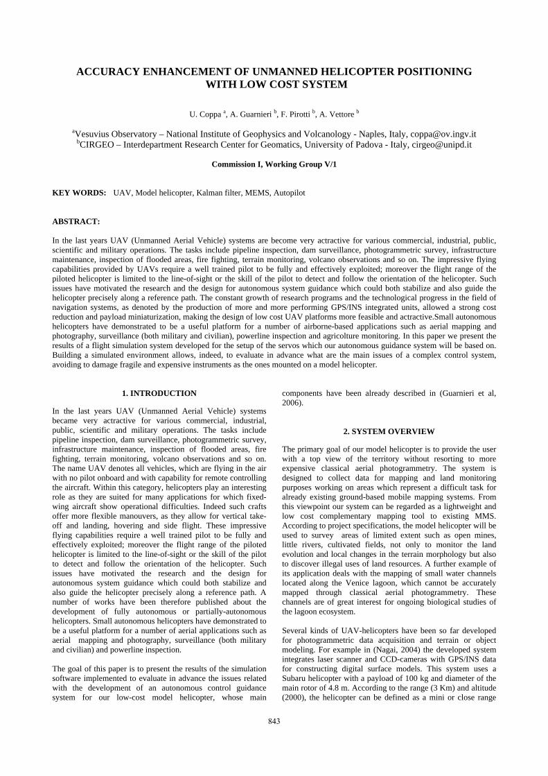
Figure 1. The model helicopter Raptor 90 v2
Fuselage length 1410 mm Fuselage width 190 mm
Height 465 mm Main rotor diameter 1580 mm Tail rotor diameter 260 mm
Total weight 4.8 kg
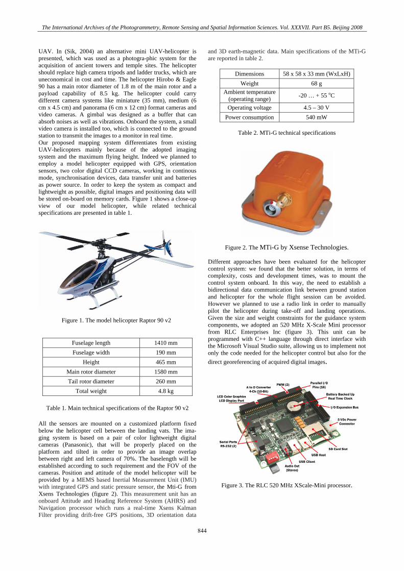
Table 1. Main technical specifications of the Raptor 90 v2 All the sensors are mounted on a customized platform fixed below the helicopter cell between the landing vats. The ima-ging system is based on a pair of color lightweight digital cameras (Panasonic), that will be properly placed on the platform and tilted in order to provide an image overlap between right and left camera of 70%. The baselength will be established according to such requirement and the FOV of the cameras. Position and attitude of the model helicopter will be provided by a MEMS based Inertial Measurement Unit (IMU) with integrated GPS and static pressure sensor, the Mti-G from Xsens Technologies (figure 2). This measurement unit has an onboard Attitude and Heading Reference System (AHRS) and Navigation processor which runs a real-time Xsens Kalman Filter providing drift-free GPS positions, 3D orientation data
and 3D earth-magnetic data. Main specifications of the MTi-G are reported in table 2.
Dimensions 58 x 58 x 33 mm (WxLxH)Weight 68 g
Ambient temperature(operating range) -20 … + 55 oC
Operating voltage 4.5 – 30 V Power consumption 540 mW
Table 2. MTi-G technical specifications
Figure 2. The MTi-G by Xsense Technologies.
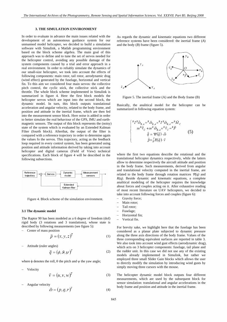
Different approaches have been evaluated for the helicopter control system: we found that the better solution, in terms of complexity, costs and development times, was to mount the control system onboard. In this way, the need to establish a bidirectional data communication link between ground station and helicopter for the whole flight session can be avoided. However we planned to use a radio link in order to manually pilot the helicopter during take-off and landing operations. Given the size and weight constraints for the guidance system components, we adopted an 520 MHz X-Scale Mini processor from RLC Enterprises Inc (figure 3). This unit can be programmed with C++ language through direct interface with the Microsoft Visual Studio suite, allowing us to implement not only the code needed for the helicopter control but also for the direct georeferencing of acquired digital images.
Figure 3. The RLC 520 MHz XScale-Mini processor.
The International Archives of the Photogrammetry, Remote Sensing and Spatial Information Sciences. Vol. XXXVII. Part B5. Beijing 2008
844
3. THE SIMULATION ENVIRONMENT
In order to evaluate in advance the main issues related with the development of an autonomous guidance system for our unmanned model helicopter, we decided to build a simulation software with Simulink, a Matlab programming environment based on the block scheme algebra. The main goal of this approach was to define and to tune the set of servos needed for the helicopter control, avoiding any possible damage of the system components caused by a trial and error approach in a real environment. In order to reliably simulate the dynamics of our small-size helicopter, we took into account the effects of following components: main rotor, tail rotor, aerodynamic drag (wind effect) generated by the fuselage, horizontal and vertical fin. To this aim we considered four main servos: the collective pitch control, the cyclic stick, the collective stick and the throttle. The whole block scheme implemented in Simulink is summarized in figure 4. Here the first block models the helicopter servos which are input into the second block, the dynamic model. In turn, this block outputs translational acceleration and angular velocity, related to the body frame, and position and attitude in the inertial frame, which are then fed into the measurement sensor block. Here noise is added in order to better simulate the real behaviour of the GPS, IMU and earth-magnetic sensors. The output of this block represents the (noisy) state of the system which is evaluated by an Extended Kalman Filter (fourth block). Afterthat, the output of the filter is compared with a reference trajectory in order to determine again the values fo the servos. This trajectory, acting as the feedback loop required in every control system, has been generated using position and attitude information derived by taking into account helicopter and digital cameras (Field of View) technical specifications. Each block of figure 4 will be described in the following subsections.
Figure 4. Block scheme of the simulation environment.
3.1 The dynamic model
The Raptor 90 has been modeled as a 6 degree of freedom (dof) rigid body (3 rotations and 3 translations), whose state is described by following measurements (see figure 5): − Center of mass position
(1)
− Attitude (euler angles)
(2)
where φ denotes the roll, θ the pitch and ψ the yaw angle; − Velocity
(3)
− Angular velocity
(4)
As regards the dynamic and kinematic equations two different reference systems have been considered: the inertial frame (A) and the body (B) frame (figure 5).
Figure 5. The inertial frame (A) and the Body frame (B)
Basically, the analitical model for the helicopter can be summarized in following equation system:
(5)
where the first two equations describe the rotational and the translational helicopter dynamics respectively, while the latters allow to determine respectively the aircraft attitude and position in the body frame. Such measurements, derived from angular and translational velocity computed in the inertial frame, are related to the body frame through rotation matrices Ψ(q) and R(q). Beside dynamic and kinematic equations, a complete analitical modeling of the helicopter requires the knowledge about forces and couples acting on it. After exhaustive reading of most recent literature on UAV helicopters, we decided to take into account following forces and couples (figure 6): − Gravity force; − Main rotor; − Tail rotor; − Fuselage; − Horizontal fin; − Vertical fin. For brevity sake, we highlight here that the fuselage has been considered as a planar plate subjected to dynamic pressure along the three axis directions of the body frame. Values of the three corresponding equivalent surfaces are reported in table 3. We also took into account wind gust effects (aerodynamic drag), which acts on 3 helicopter components: fuselage, tail plane and the rudder unit. In this case we did not use any of the existing models already implemented in Simulink, but rather we employed three small Slider Gain blocks which allows the user to directly modify the simulation by introducing wind gusts by simply moving three cursors with the mouse. The helicopter dynamic model block outputs four different measurements, which are used by the subsequent block for sensor simulation: translational and angular accelerations in the body frame and position and attitude in the inertial frame.
The International Archives of the Photogrammetry, Remote Sensing and Spatial Information Sciences. Vol. XXXVII. Part B5. Beijing 2008
845
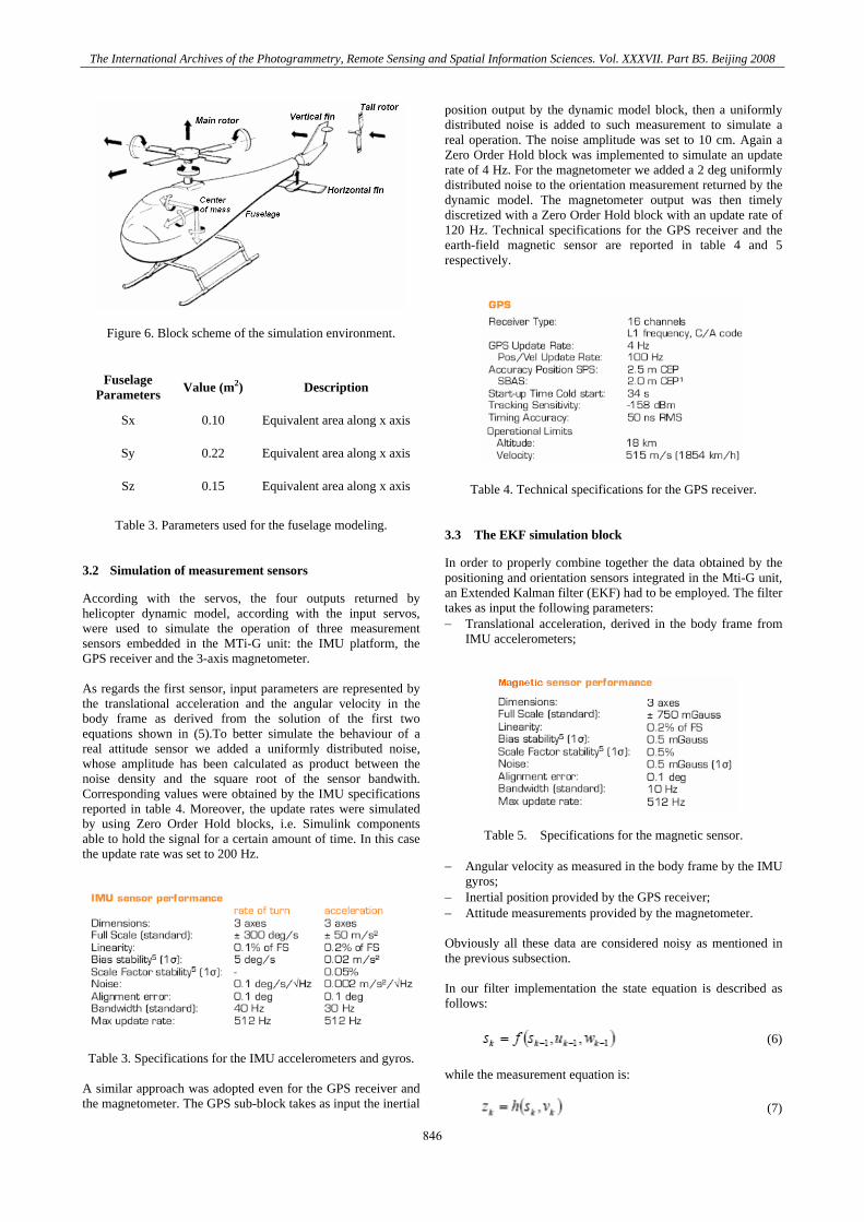
Figure 6. Block scheme of the simulation environment.
Fuselage Parameters Value (m2) Description
Sx 0.10 Equivalent area along x axis
Sy 0.22 Equivalent area along x axis
Sz 0.15 Equivalent area along x axis
Table 3. Parameters used for the fuselage modeling.
3.2 Simulation of measurement sensors
According with the servos, the four outputs returned by helicopter dynamic model, according with the input servos, were used to simulate the operation of three measurement sensors embedded in the MTi-G unit: the IMU platform, the GPS receiver and the 3-axis magnetometer. As regards the first sensor, input parameters are represented by the translational acceleration and the angular velocity in the body frame as derived from the solution of the first two equations shown in (5).To better simulate the behaviour of a real attitude sensor we added a uniformly distributed noise, whose amplitude has been calculated as product between the noise density and the square root of the sensor bandwith. Corresponding values were obtained by the IMU specifications reported in table 4. Moreover, the update rates were simulated by using Zero Order Hold blocks, i.e. Simulink components able to hold the signal for a certain amount of time. In this case the update rate was set to 200 Hz.
Table 3. Specifications for the IMU accelerometers and gyros. A similar approach was adopted even for the GPS receiver and the magnetometer. The GPS sub-block takes as input the inertial
position output by the dynamic model block, then a uniformly distributed noise is added to such measurement to simulate a real operation. The noise amplitude was set to 10 cm. Again a Zero Order Hold block was implemented to simulate an update rate of 4 Hz. For the magnetometer we added a 2 deg uniformly distributed noise to the orientation measurement returned by the dynamic model. The magnetometer output was then timely discretized with a Zero Order Hold block with an update rate of 120 Hz. Technical specifications for the GPS receiver and the earth-field magnetic sensor are reported in table 4 and 5 respectively.
Table 4. Technical specifications for the GPS receiver. 3.3 The EKF simulation block
In order to properly combine together the data obtained by the positioning and orientation sensors integrated in the Mti-G unit, an Extended Kalman filter (EKF) had to be employed. The filter takes as input the following parameters: − Translational acceleration, derived in the body frame from
IMU accelerometers;
Table 5. Specifications for the magnetic sensor. − Angular velocity as measured in the body frame by the IMU
gyros; − Inertial position provided by the GPS receiver; − Attitude measurements provided by the magnetometer. Obviously all these data are considered noisy as mentioned in the previous subsection. In our filter implementation the state equation is described as follows:
(6)
while the measurement equation is:
(7)
The International Archives of the Photogrammetry, Remote Sensing and Spatial Information Sciences. Vol. XXXVII. Part B5. Beijing 2008
846
he state vector at tim kT e step k (s ) ensambles four variables
related to the inertial frame: position, orientation, translational velocity and angular velocity. For brevity sake we report here just the equations we used for the translational dynamic (eq. 8), the rotational dynamic (eq. 9) and for the state measurements (eq. 10-13).
(8
)
(9
)
(10)
here I
BR denotes the ro ion matrix converting attitude and w tatposition data from the Body frame to the Inertial frame.
(11)
(12)
(13)
.4 The reference trajectory
t of Simulink blocks we used
ng area should have a rectangular shape; the
hould be automatically generated once the
elicopter starting
ages had to be captured in hovering mode, i.e.
h a way to ensure
e designed taking into account the use of
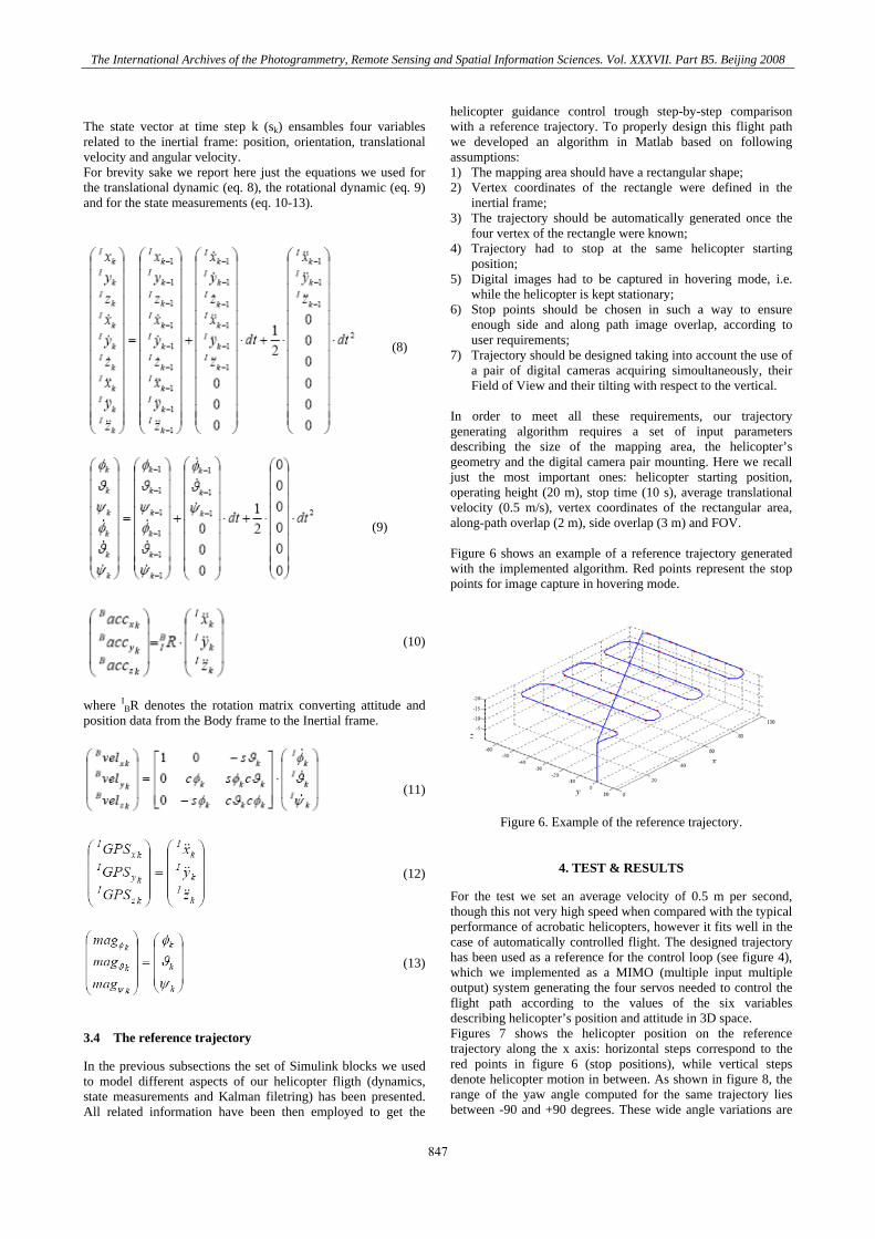
order to meet all these requirements, our trajectory
igure 6 shows an example of a reference trajectory generated
3
In the previous subsections the seto model different aspects of our helicopter fligth (dynamics, state measurements and Kalman filetring) has been presented. All related information have been then employed to get the
helicopter guidance control trough step-by-step comparison with a reference trajectory. To properly design this flight path we developed an algorithm in Matlab based on following assumptions: 1) The mappi2) Vertex coordinates of the rectangle were defined in
inertial frame; 3) The trajectory s
four vertex of the rectangle were known; 4) Trajectory had to stop at the same h
position; 5) Digital im
while the helicopter is kept stationary; 6) Stop points should be chosen in suc
enough side and along path image overlap, according to user requirements;
7) Trajectory should ba pair of digital cameras acquiring simoultaneously, their Field of View and their tilting with respect to the vertical.
Ingenerating algorithm requires a set of input parameters describing the size of the mapping area, the helicopter’s geometry and the digital camera pair mounting. Here we recall just the most important ones: helicopter starting position, operating height (20 m), stop time (10 s), average translational velocity (0.5 m/s), vertex coordinates of the rectangular area, along-path overlap (2 m), side overlap (3 m) and FOV. Fwith the implemented algorithm. Red points represent the stop points for image capture in hovering mode.
Figure 6. Example of t eference trajectory.
4. TEST & RESULTS
For the test we set an .5 m per second,
erence
he r
average velocity of 0though this not very high speed when compared with the typical performance of acrobatic helicopters, however it fits well in the case of automatically controlled flight. The designed trajectory has been used as a reference for the control loop (see figure 4), which we implemented as a MIMO (multiple input multiple output) system generating the four servos needed to control the flight path according to the values of the six variables describing helicopter’s position and attitude in 3D space. Figures 7 shows the helicopter position on the reftrajectory along the x axis: horizontal steps correspond to the red points in figure 6 (stop positions), while vertical steps denote helicopter motion in between. As shown in figure 8, the range of the yaw angle computed for the same trajectory lies between -90 and +90 degrees. These wide angle variations are
The International Archives of the Photogrammetry, Remote Sensing and Spatial Information Sciences. Vol. XXXVII. Part B5. Beijing 2008
847
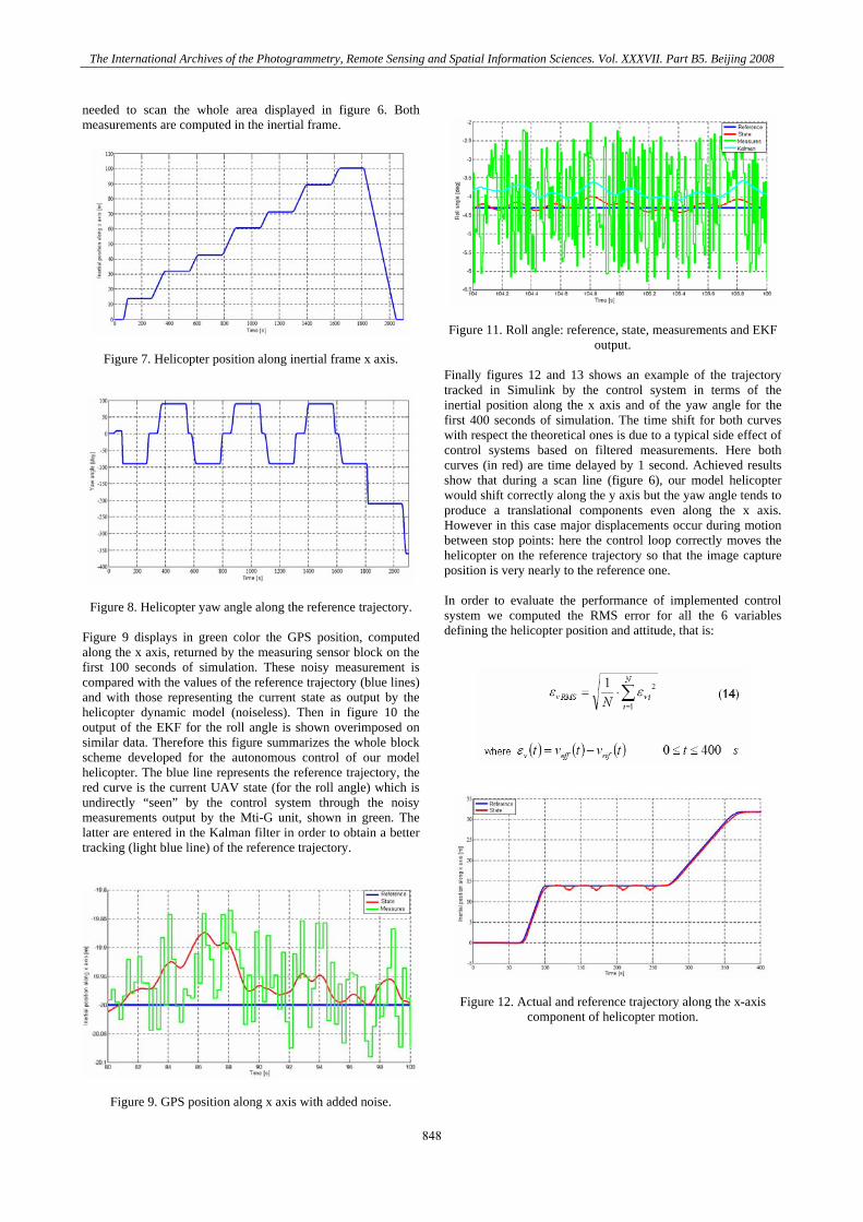
needed to scan the whole area displayed in figure 6. Both measurements are computed in the inertial frame.
Figure 7. Helicopter position along inertial frame x axis.
Figure 8. Helicopter yaw angle along the reference trajectory. Figure 9 displays in green color the GPS position, computed along the x axis, returned by the measuring sensor block on the first 100 seconds of simulation. These noisy measurement is compared with the values of the reference trajectory (blue lines) and with those representing the current state as output by the helicopter dynamic model (noiseless). Then in figure 10 the output of the EKF for the roll angle is shown overimposed on similar data. Therefore this figure summarizes the whole block scheme developed for the autonomous control of our model helicopter. The blue line represents the reference trajectory, the red curve is the current UAV state (for the roll angle) which is undirectly “seen” by the control system through the noisy measurements output by the Mti-G unit, shown in green. The latter are entered in the Kalman filter in order to obtain a better tracking (light blue line) of the reference trajectory.
Figure 9. GPS position along x axis with added noise.
Figure 11. Roll angle: reference, state, measurements and EKF
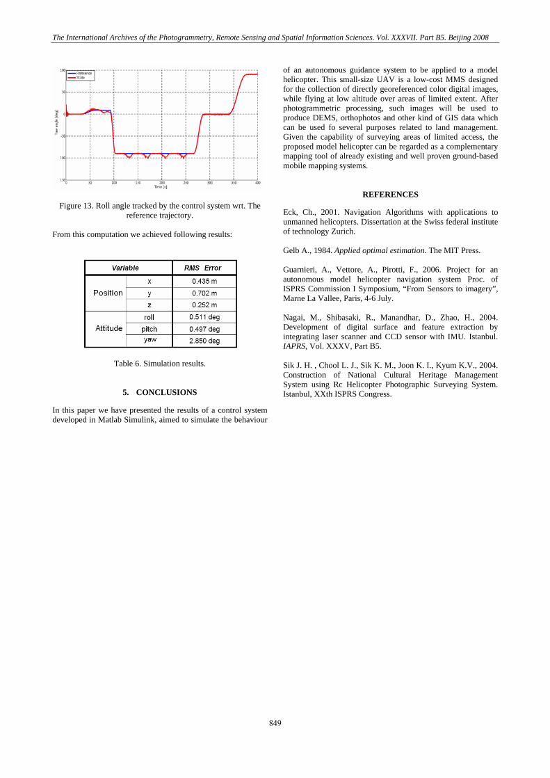
output. Finally figures 12 and 13 shows an example of the trajectory tracked in Simulink by the control system in terms of the inertial position along the x axis and of the yaw angle for the first 400 seconds of simulation. The time shift for both curves with respect the theoretical ones is due to a typical side effect of control systems based on filtered measurements. Here both curves (in red) are time delayed by 1 second. Achieved results show that during a scan line (figure 6), our model helicopter would shift correctly along the y axis but the yaw angle tends to produce a translational components even along the x axis. However in this case major displacements occur during motion between stop points: here the control loop correctly moves the helicopter on the reference trajectory so that the image capture position is very nearly to the reference one. In order to evaluate the performance of implemented control system we computed the RMS error for all the 6 variables defining the helicopter position and attitude, that is:
Figure 12. Actual and reference trajectory along the x-axis component of helicopter motion.
The International Archives of the Photogrammetry, Remote Sensing and Spatial Information Sciences. Vol. XXXVII. Part B5. Beijing 2008
848
The International Archives of the Photogrammetry, Remote Sensing and Spatial Information Sciences. Vol. XXXVII. Part B5. Beijing 2008
Figure 13. Roll angle tracked by the control system wrt. The
reference trajectory. From this computation we achieved following results:
Table 6. Simulation results.
5. CONCLUSIONS
In this paper we have presented the results of a control system developed in Matlab Simulink, aimed to simulate the behaviour
of an autonomous guidance system to be applied to a model helicopter. This small-size UAV is a low-cost MMS designed for the collection of directly georeferenced color digital images, while flying at low altitude over areas of limited extent. After photogrammetric processing, such images will be used to produce DEMS, orthophotos and other kind of GIS data which can be used fo several purposes related to land management. Given the capability of surveying areas of limited access, the proposed model helicopter can be regarded as a complementary mapping tool of already existing and well proven ground-based mobile mapping systems.
REFERENCES
Eck, Ch., 2001. Navigation Algorithms with applications to unmanned helicopters. Dissertation at the Swiss federal institute of technology Zurich. Gelb A., 1984. Applied optimal estimation. The MIT Press. Guarnieri, A., Vettore, A., Pirotti, F., 2006. Project for an autonomous model helicopter navigation system Proc. of ISPRS Commission I Symposium, “From Sensors to imagery”, Marne La Vallee, Paris, 4-6 July. Nagai, M., Shibasaki, R., Manandhar, D., Zhao, H., 2004. Development of digital surface and feature extraction by integrating laser scanner and CCD sensor with IMU. Istanbul. IAPRS, Vol. XXXV, Part B5. Sik J. H. , Chool L. J., Sik K. M., Joon K. I., Kyum K.V., 2004. Construction of National Cultural Heritage Management System using Rc Helicopter Photographic Surveying System. Istanbul, XXth ISPRS Congress.
849

The International Archives of the Photogrammetry, Remote Sensing and Spatial Information Sciences. Vol. XXXVII. Part B5. Beijing 2008
850