helicopter air data system (hads)a-1b).pdf · system (hads) has been developed to ease the...
TRANSCRIPT
GEe·Marconi Avionics Mission Avionics Division
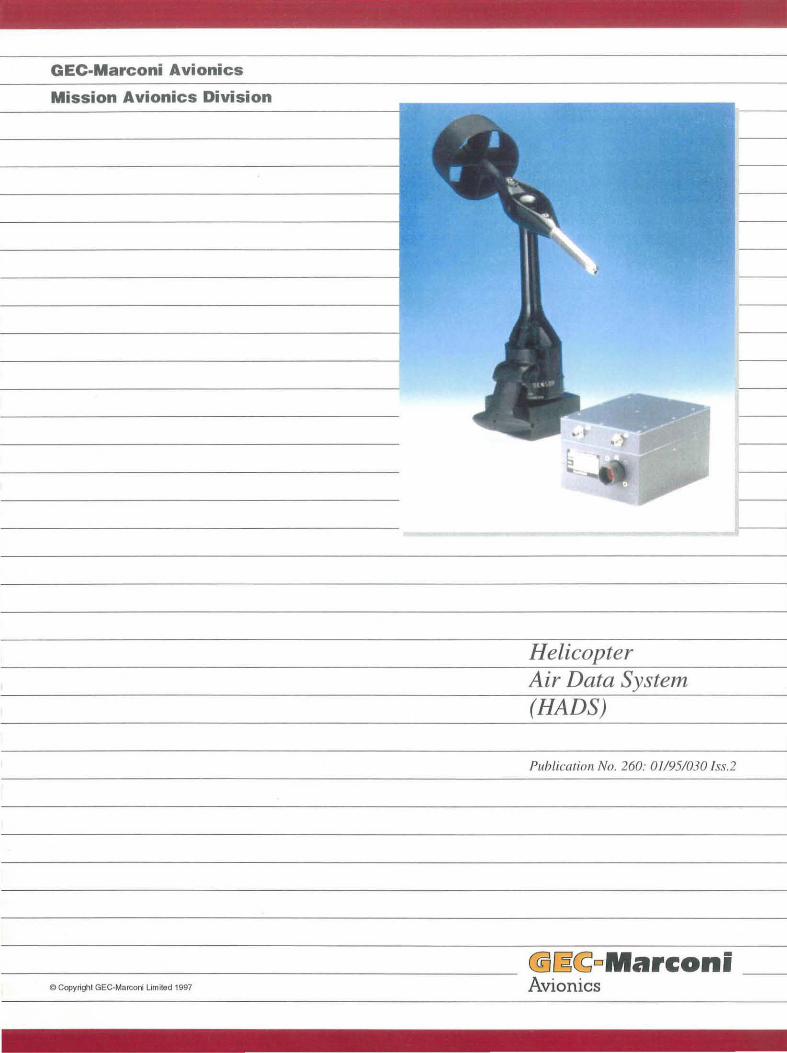
Helicopter Air Data System (HADS)
Publicatinn No. 260: 01/95/030 Iss.2
@[3~DMarconi _ C Copyrighl GEe-Marconi limited 1997 Avionics

© GEe-Marconi Avionics Limited (1995)
The copyright in this document is the property of
GEC-Marconi Avionics Limited. This document
may not be used for any purpose other than that
for which it is supplied nor shall any part of it be
reproduced or copied without the prior written
consent of GEC-Marconi Avionics Limited.
Unless GEC-Marconi Avionics Limited has
accepted a contractual obligation in respect of
the permitted use of the information and data
contained herein, such information and data is
provided without responsibility and GEC
Marconi Avionics Limited disclaim all liability
from its use.
260:01195/030 Iss. 2
HELICOPTER Am DATA SYSTEM
Introduction
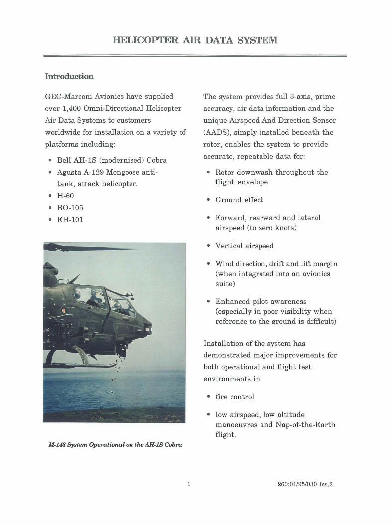
GEC-Marconi Avionics have supplied
over 1,400 Omni-Directional Helicopter
Air Data Systems to customers
worldwide for installation on a variety of
platforms including:
• Bell AH-1S (modernised) Cobra
• Agusta A-129 Mongoose anti-
tank, attack helicopter.
• H-60
• BO-105
• EH-101
M·l43 System Operational on tM AH·IS Cobra
1
The system provides full 3-axis, prime
accuracy, air data information and the
unique Airspeed And Direction Sensor
(AADS), simply installed beneath the
rotor, enables the system to provide
accurate, repeatable data for:
• Rotor downwash throughout the flight envelope
• Ground effect
• Forward, rearward and lateral airspeed (to zero knots)
• Vertical airspeed
• Wind direction, drift and lift margin (when integrated into an avionics suite)
• Enhanced pilot awareness (especially in poor visibility when reference to the ground is difficult)
Installation of the system has
demonstrated major improvements for
both operational and flight test
environments in:
• fire control
• low airspeed, low altitude manoeuvres and Nap-of-the-Earth flight.
260:01195/030 166.2
Cobra AH-1S M143 Fire and Flight Helicopter Air Data System
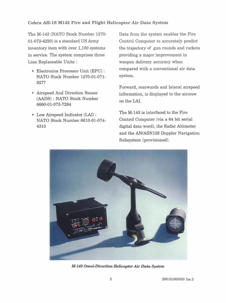
The M-143 (NATO Stock Number 1270-
01-072-4220) is a standard US Army
inventory item with over 1,100 systems
in service. The system comprises three
Line Replaceable Units:
• Electronics Processor Unit (EPU) : NATO Stock Number 1270-01-071-9277
• Airspeed And Direction Sensor (AADS) : NATO Stock Number 6660-01-073-7284
• Low Airspeed Indicator (LAI) : NATO Stock Number 6610-01-074-4313
Data from the system enables the Fire
Control Computer to accurately predict
the trajectory of gun rounds and rockets
providing a major improvement in
weapon delivery accuracy when
compared with a conventional air data
system.
Forward, rearwards and lateral airspeed
information, is displayed to the aircrew
on the LAI.
The M-143 is interfaced to the Fire
Control Computer (via a 64 bit serial
digital data word), the Radar Altimeter
and the AN/ASN128 Doppler Navigation
Subsystem (provisioned).
M-143 Omni-Direction Helicopter Air Data System
2 260:01/95/030 Iss.2
MIL-STD·1553B Helicopter Air Data System (BADS)
The MIL·STD·1553B Helicopter Air Data
System (HADS) has been developed to
ease the integration of the system with
modern avionics suites.
The system utilizes the AADS probe and
replaces the EPU with a High
Integration Air Data Computer (HIADC)
that provides MIL·STD-1553 and RS 485
interfaces.
The HIADC has been successfully
proven on a number of platforms and is
applicable to both fixed and rotary wing
aircraft.
By incorporating the AADS analog
interfaces and the omni-directional air
data software in the fixed wing HIADC
SINGLE AXIS
P.
~ P' .tZ T~P~
Conventional Sensors
OMNI-DIRECTIONAL
umatic Pne Inte rfaces
P. a::::: Pt a::
ctrleal
TRANSDUCERS
INPUT
-
Pt Imp ~ El. 10' ertaces
q INTERFACES =-Integral Sensors
~
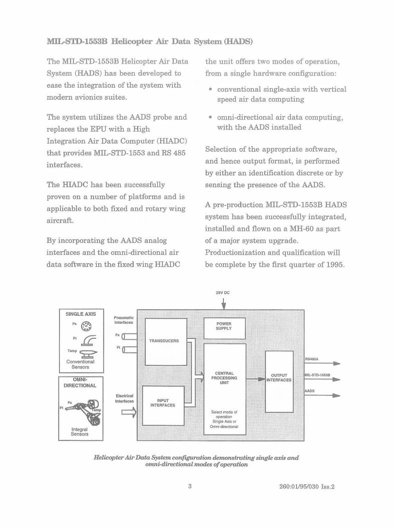
the unit offers two modes of operation,
from a single hardware configuration:
• conventional single-axis with vertical speed air data computing
• omni-directional air data computing, with the AADS installed
Selection of the appropriate software,
and hence output format, is performed
by either an identification discrete or by
sensing the presence of the AADS.
A pre-production MIL-STD-1553B HADS
system has been successfully integrated,
installed and flown on a MH-60 as part
of a major system upgrade.
Productionization and qualification will
be complete by the first quarter of 1995.
28VDC , POWER SUPPLY
RS48SA
CENTRAL OUTPUT MIL·STD-1553B PROCESSING
UNIT INTERFACES
AAOS
Select mode of operation
Single Axis or Omni-directional
Helicopter Air Data System configuration demonstrating single axis and omni-directional modes of operation
3 260:01/95/030 155.2
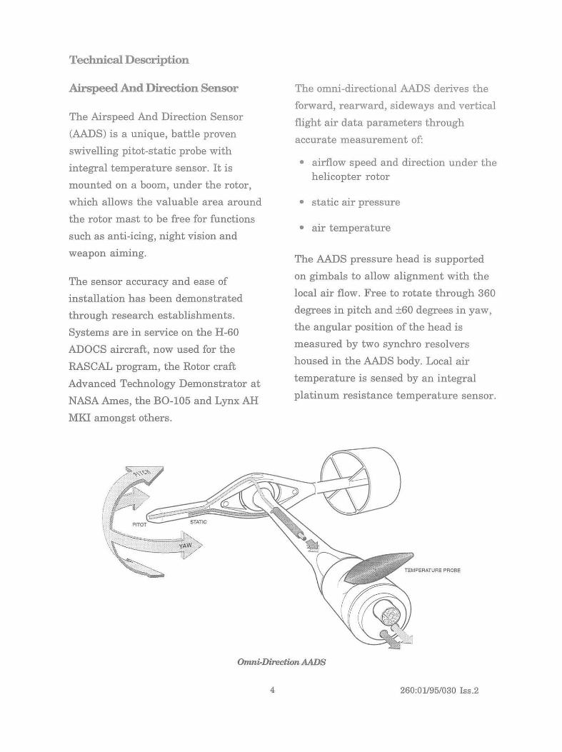
Technical Description
Airspeed And Direction Sensor
The Airspeed And Direction Sensor
(AADS) is a unique, battle proven
swivelling pitot-static probe with
integral temperature sensor. It is
mounted on a boom, under the rotor,
which allows the valuable area around
the rotor mast to be free for functions
such as anti-icing, night vision and
weapon aiming.
The sensor accuracy and ease of
installation has been demonstrated
through research establishments.
Systems are in service on the H-60
ADOCS aircraft, now used for the
RASCAL program, the Rotor craft
Advanced Technology Demonstrator at
NASA Ames, the BO-105 and Lynx AH
MKI amongst others.
The omni-directional AADS derives the
forward, rearward, sideways and vertical
flight air data parameters through
accurate measurement of:
• airflow speed and direction under the helicopter rotor
• static air pressure
• air temperature
The AADS pressure head is supported
on gimbals to allow alignment with the
local air flow. Free to rotate through 360
degrees in pitch and ±60 degrees in yaw,
the angular position of the head is
measured by two synchro resolvers
housed in the AADS body. Local air
temperature is sensed by an integral
platinum resistance temperature sensor.
Omni-Direction AADS
4 260:01195/030 Iss .2
At high forward airspeeds, the AADS is
unaffected by rotor downwash and
behaves as a conventional pitot-static
probe, a ligning itself with the local
airflow. The sensed airflow angles are
therefore the helicopter's angle-of
attack and angle-of-sideslip, which are
used to resolve the measured airspeed
into the forward, lateral and vertical
airspeed components. At low airspeeds
rotor downwash becomes the dominant
airflow component; the resulting head
angle and measured downwash velocity
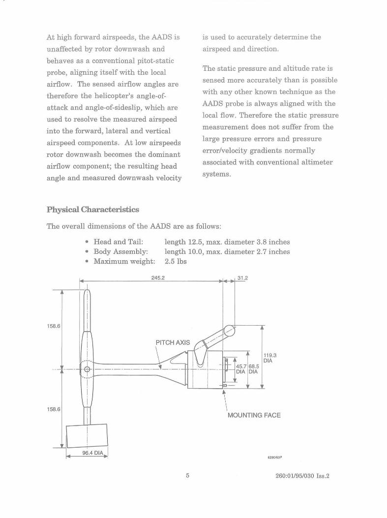
Physical Characteristics
is used to accurately determine the
airspeed and direction.
The static pressure and altitude rate is
sensed more accurately than is possible
with any other known technique as the
AADS probe is always aligned with the
local flow. Therefore the static pressure
measurement does not suffer from the
large pressure errors and pressure
error/velocity gradients normally
associated with conventional altimeter
systems.
The overall dimensions of the AADS are as follows:
I
58.6
• Head and Tail: • Body Assembly: • Maximum weight:
245.2
r I
length 12.5, max. diameter 3.8 inches length 10.0, max. diameter 2.7 inches 2.5 1bs
31.2
i PITCH AXIS d lY i \ I'->V -- ---- .+ ____________ -=f~ N --~
'T ______ 145.768.5
DIA DIA
119.3 DIA
I ~~\~~~
J I I
158.6 MOUNTING FACE
96.4 DIA 6280160P
5 260:01195/030 Iss.2
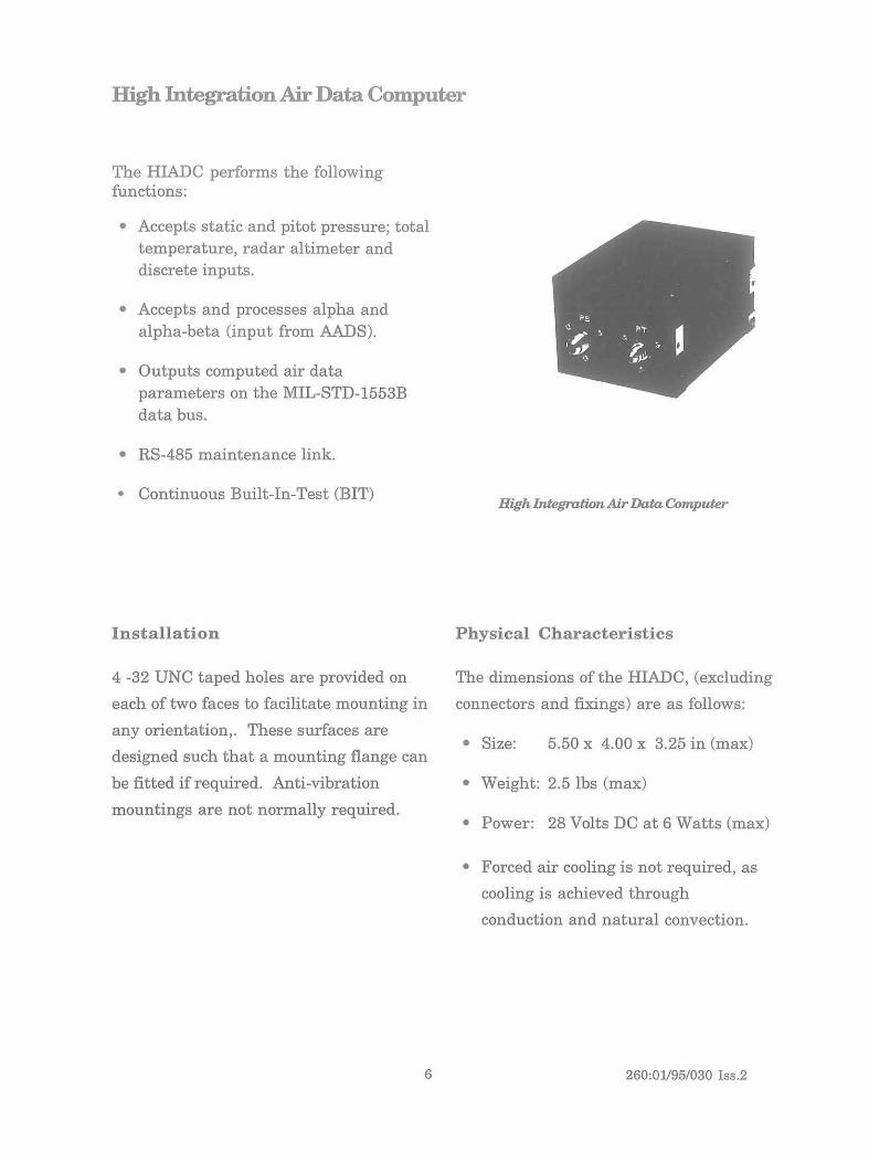
High Integration Air Data Computer
The HIADC performs the following functions:
• Accepts static and pitot pressure; total temperature, radar altimeter and discrete inputs.
• Accepts and processes alpha and alpha-beta (input from AADS).
• Outputs computed air data parameters on the MIL-STD-1553B data bus.
• RS-485 maintenance link.
• Continuous Built-In-Test (BIT)
Installation
4 -32 UNC taped holes are provided on
each of two faces to facilitate mounting in
any orientation,. These surfaces are
designed such that a mounting flange can
be fitted if required. Anti-vibration
mountings are not normally required.
6
High IntegrotionAir Data Computer
Physical Characteristics
The dimensions of the HIADC, (excluding
connectors and fixings) are as follows:
• Size: 5.50 x 4.00 x 3.25 in (max)
• Weight: 2.5 lbs (max)
• Power: 28 Volts DC at 6 Watts (max)
• Forced air cooling is not required, as
cooling is achieved through
conduction and natural convection.
260:01195/030 Iss.2
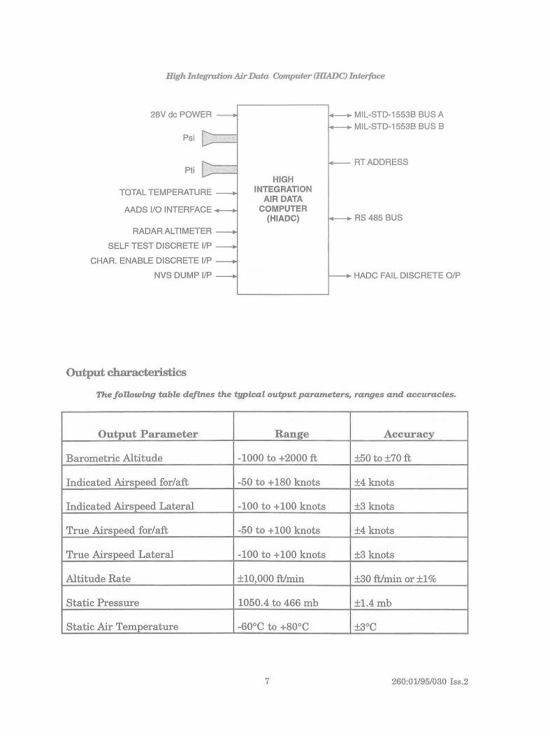
High Inregra/Wn Air Data Compuler (HlADC) Inrer/iu!e
28Vdc POWER
Psi
Pli
TOTAL TEMPERATURE
AADS 1/0 INTERFACE
RADAR ALTIMETER
SELF TEST DISCRETE liP
CHAR. ENABLE DISCRETE liP
NVS DUMP liP
Output characteristics
HIGH INTEGRATION
AIR DATA COMPUTER
(HIADC)
MIL-STD-1553B BUSA MIL-STD-1553B BUS B
RTADDRESS
RS 485 BUS
_ HADC FAIL DISCRETE OIP
ThefollDwing table defines the typical output parameters, ranges and accuracies_
Output Parameter Range Accuracy
Barometric Altitude -1000 to +2000 ft +50 to +70 ft
Indicated Airspeed for/aft -50 to + 180 knots +4 knots
Indicated Airspeed Lateral -100 to +100 knots +3 knots
True Airspeed for/aft -50 to + 100 knots +4 knots
True Airspeed Lateral -100 to +100 knots +3 knots
Altitude Rate +10,000 ftlmin +30 ftlmin or +1%
Static Pressure 1050.4 to 466 mb +l.4mb
Static Air Temperature -60°C to +80°C +3°C
7 260:01195/030 Iss.2
Installation and Characterization
Every aircraft is unique in design and
therefore the flight characteristics and
airflow around the airframe must be
analyzed.
Corrective measures within the HIADC
software ensure that a high level of
output accuracy is achieved and
maintained throughout the entire flight
envelope, especially at low airspeeds
and when close to the ground.
Although the design of the HADS has
been standardised to keep program costs
to an absolute minimum, characteriz
ation of the AADS will normally be
required. To ensure program success, it
is therefore important that adequate
provision is made for:
• Initial installation trials
• Flight data acquisition
• Ground data analysis
• System characterization
• Verification flight.
AADS Installation To achieve optimum performance, the
following general criteria should be
considered when determining the
location of the AADS.
The AADS should be:
• Mounted forward of the rotor mast and at least 27 inches within the fully developed section of the blade
• At least 18 inches below the lowest possible position of the rotor blade.
8
• Sufficiently clear from the fuselage to allow freedom of movement within the airflow
• Clear of engine inlet and exhaust ports (including external stores)
• Clear of crew access points
• The sensor should remain within the rotor wake at airspeeds below 25 knots
Once installed the AADS design allows;
• removal and replacement within one minute, using standard tools
• accurate re-alignment of the installed AADS
HIADC Characterization Each helicopter type exhibits particular
differences due to fuselage, downwash
and ground effect. These conditions are
corrected during normal operation by
embedded characterization software.
It is therefore important that adequate
dedicated flying time is allocated to
ensure that sufficient quality data is
acquired during flight trials. This test
data will then be analyzed to identify the
repeatable errors and to formalise the
correction curves within the software.
The HIADC, with the resultant
characterized software is then returned
for a verification flight before
incorporation of the final software
standard into the production hardware.
260:01195/030 Iss.2