heka certitfikat zertifikat zulassung - heka-online.de · nungsmessverstärker (15 v, dc),...
TRANSCRIPT
Mobi l i tä t
TÜV NORD Mobi l i tä t GmbH & Co. KG
IFM – Institut für Fahr-zeugtechnik und Mobilität
Adlerstraße 7
45307 Essen
Tel.: +49 (0)201 825-4120
Fax: +49 (0)201 825-4150
www.tuev-nord.de
Sitz des Unternehmens:
Hannover
Handelsregister
HRA 27006
Geschäftsführung:
Dr. Klaus Kleinherbers
BP247-0_B_DE.DOC
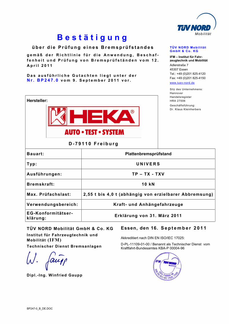
B e s t ä t i g u n gü b e r d i e P r ü f u n g e i n e s B r e m s p r ü f s t a n d e s
g e m ä ß d e r R i c h t l i n i e f ü r d i e A n w e n d u n g , B e s c h a f -f e n h e i t u n d P r ü f u n g v o n B r e m s p r ü f s t ä n d e n v o m 1 2 . A p r i l 2 0 1 1
D a s a u s f ü h r l i c h e G u t a c h t e n l i e g t u n t e r d e r N r . B P 2 4 7 . 0 v o m 9 . S e p t e m b e r 2 0 1 1 v o r .
Hersteller:
D - 7 9 1 1 0 F r e i b u r g
Bauart: Plattenbremsprüfstand
Typ: U N I V E R S
Ausführungen: TP – TX - TXV
Bremskraft: 10 kN
Max. Prüfachslast: 2,55 t bis 4,0 t (abhängig von erzielbarer Abbremsung)
Verwendungsbereich: Kraft- und Anhängefahrzeuge
EG-Konformitätser-klärung:
Erklärung von 31. März 2011
TÜV NORD Mobilität GmbH & Co. KG
Institut für Fahrzeugtechnik und Mobil i tät (IFM)
Technischer Dienst Bremsanlagen
Dipl . - Ing. Winfried Gaupp
Essen, den 16. S e p t e m b e r 2 0 1 1
Akkreditiert nach DIN EN ISO/IEC 17025:
D-PL-11109-01-00 / Benannt als Technischer Dienst vom Kraftfahrt-Bundesamtes KBA-P 00004-96
BP247-0_B_EN.DOC
Mobi l i tä t
TÜV NORD Mobi l i tä t GmbH & Co. KG
IFM – Institute for Vehicle Technology and Mobility
Adlerstraße 7
45307 Essen
Tel.: +49 (0)201 825-4120
Fax: +49 (0)201 825-4150
www.tuev-nord.de
Corporate seat: Hannover
Commercial Register
section
HRA 27006
Management:
Dr. Klaus Kleinherbers
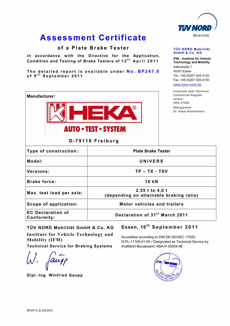
Assessment Certif icateo f a P l a t e B r a k e T e s t e r
in accordance with the Directive for the Application, Condit ion and Testing of Brake Testers of 1 2 t h A p r i l 2 0 1 1
T h e d e t a i l e d r e p o r t i s a v a i l a b l e u n d e r N o . B P 2 4 7 . 0o f 9 t h S e p t e m b e r 2 0 1 1
Manufacturer:
D - 7 9 1 1 0 F r e i b u r g
Type of construction: Plate Brake Tester
Model: U N I V E R S
Versions: TP – TX - TXV
Brake force: 10 kN
Max. test load per axle: 2,55 t to 4,0 t
(depending on attainable braking ratio)
Scope of application: Motor vehicles and trailers
EC Declaration of Conformity:
Declaration of 31s t March 2011
TÜV NORD Mobilität GmbH & Co. KG
Institute for Vehicle Technology and
Mobility (IFM)
Technical Service for Braking Systems
Dipl . - Ing. Winfried Gaupp
Essen, 16 th S e p t e m b e r 2 0 1 1
Accredited according to DIN EN ISO/IEC 17025:
D-PL-11109-01-00 / Designated as Technical Service by
Kraftfahrt-Bundesamt: KBA-P 00004-96

BP247-0.DOC
Mobi l i tä t
TÜV NORD Mobi l i tä t GmbH & Co. KG
IFM – Institut für Fahr-zeugtechnik und Mobilität
Adlerstraße 7
45307 Essen
Tel.: +49 (0)201 825-4120
Fax: +49 (0)201 825-4150
www.tuev-nord.de
Sitz des Unternehmens:
Hannover
Handelsregister
HRA 27006
Geschäftsführung:
Dr. rer.nat. K. Kleinherbers
G u t a c h t e n
N r . B P 2 4 7 . 0
ü b e r d i e P r ü f u n g e i n e s B r e m s p r ü f s t a n d e s
g e m ä ß d e r R i c h t l i n i e f ü r d i e A n w e n d u n g , B e s c h a f -f e n h e i t u n d P r ü f u n g v o n B r e m s p r ü f s t ä n d e n v o m 1 2 . A p r i l 2 0 1 1
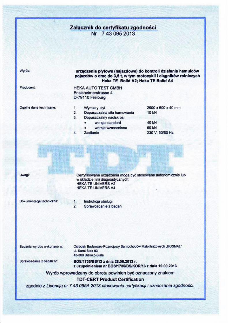
1. Allgemeine Angaben
1.1 Marke / Handelsbezeichnung: HEKA AUTO TEST SYSTEM
1.2 Hersteller: HEKA AUTO TEST GmbH
Ensisheimer Str. 4
D - 79110 Freiburg
1.3 Antragsteller: siehe Absatz 1.2
1.4 Bauart: P l a t t e n b r e m s p r ü f s t a n d
1.5 Typ: UNIVERS
1.6 Ausführung:
Zweiplattenausführung: TP (ohne Spurprüfung)
TX (mit Spurprüfung)
Vierplattenausführung: TXV (mit Spurprüfung)
1.6.1 Ausrüstungsvarianten
Einbauvarianten: UF (Unterflur)
ÜF (Überflur)
Alle Plattenausführungen können sowohl als UF als auch ÜF installiert werden
G u t a c h t e n N r . B P 2 4 7 . 0
Hersteller: HEKA AUTO TEST GMBH
Typ: UNIVERS Seite 2 / 1 6
BP247-0.DOC
2 Verwendungsbereich
2.1 Fahrzeugart: Kraft- und Anhängefahrzeuge
2.2 Antriebsart:
2.2.1 Fahrzeuge ohne oder mit ab-schaltbarem Allradantrieb: s i n d p r ü f b a r
2.2.2 Fahrzeuge mit permanentemAllradantrieb: Diese Fahrzeuge sind b e d i n g t prüfbar:
- Allradfahrzeuge mit geringer Kraftübertragung oder im Prüfzustand getrenntem Allradantrieb s i n dp r ü f b a r .
- Allradfahrzeuge mit hoher Kraftübertragungsrate (starre oder „quasistarre“ Allradverbindung) wäh-rend der Bremsprüfung s i n d n i c h t p r ü f -b a r . *
* s i e h e j e d o c h A n m e r k u n g b e z ü g -l i c h d e r G e s a m t a b b r e m s u n g b e i d e r 4 P l a t t e n a u s f ü h r u n g i m A b -s a t z 4 . 1 „ A l l r a d b e t r i e b “ .
3 Technische Angaben
3.1 Identifikation: Die komplette Ausrüstung des Bremsprüfstands wird durch Typenschilder an der E-BOX (Prüfstandselektro-nik) und an jedem der Bremssegmente (innen) gekenn-zeichnet.
Das Typenschild an der E BOX enthält unter anderem folgende Angaben :
- Hersteller
- Typ und Ausführungsbezeichnung
- Baujahr
- Maschinennummer (fortlaufende Nummer)
- „Seriennummer“ (elektronischer Code)
- Spannungsversorgung
- Stromaufnahme
3.2 Überfahrlast / Prüflast
3.2.1 Maximale Überfahrlast: 4 t (Herstellerangabe)
3.2.2 Maximale Prüflast: siehe Tabelle des Absatzes 4.4.1
G u t a c h t e n N r . B P 2 4 7 . 0
Hersteller: HEKA AUTO TEST GMBH
Typ: UNIVERS Seite 3 / 1 6
BP247-0.DOC
3.3 Nominale maximale Bremskraft pro Rad: siehe Tabelle des Absatzes 4.4.1
3.4 Bremsprüfplatten
3.4.1 Anzahl: 2 bzw. 4 (siehe oben Absatz 1.6)
3.4.2 Breite: 600 mm
3.4.3 Länge: 1840 mm
3.4.4 Plattenüberhöhung: 0 mm (UF) bzw. 40 mm (ÜF)
3.4.5 Oberfläche: Stahlplatte mit aufgeschweißtem Streckmetall, pulverbeschichtet
3.5 Prüfgeschwindigkeit: 8 bis 12 km/h (Ausgangsgeschwindigkeit v0)
3.6 Betriebsspannung: Eingang: 100 bis 240 V, 50/60 Hz
Ausgang: 15 V - DC
zwei identische Netzteile (Versorgungsspannung für E-Box/Kraftsensor und Display)
3.7 Laufrollen: entfällt
3.8 Prüfbare Radgröße: ohne Einschränkung
3.9 Art des Messsystem: Die Bremsplatten sind auf Kugelbahnen gelagert und sind über einen DMS-Zugkraftsensor mit dem Boden-rahmen verbunden, der alle auf die Bremsplatte wir-kenden Kräfte in Fahrtrichtung aufnimmt.
Die Aufbereitung der Messwerte erfolgt durch ein elektronisches Messsystem.
Messkette:
DMS-Zugkraftsensor mit integriertem Gleichspan-nungsmessverstärker (15 V, DC), Mikroprozessor mit integrierten A/D-Wandlern, serielle Ausgabe der Daten an die PC-Schnittstelle, Weiterverarbeitung der Daten im PC-Programm mit Ausgabe der Messergebnisse (PC / Drucker / Display; siehe Absatz 3.10).
G u t a c h t e n N r . B P 2 4 7 . 0
Hersteller: HEKA AUTO TEST GMBH
Typ: UNIVERS Seite 4 / 1 6
BP247-0.DOC
3.10 Anzeige / Ausgabe der Messergebnisse
3.10.1 Analog: entfällt
3.10.2 Digital: 3-stellige Messwertausgabe
Anzeige: Die Messwertausgabe erfolgt auf dem Display achs-weise jeweils links und rechts.
Bei der Vierplattenausführung erscheinen zunächst die gemessenen Bremswerte der Vorderachse und mit einer Zeitverzögerung die Bremswerte der Hinterachse.
Der Zeitverzug der Anzeige ist parametrierbar von 0 bis 99 Sekunden (Defaultwert 4,6 s).
Differenzanzeige; siehe unten Absatz 4.3.5
Zweiplattenausführung:
- Bedienerführung durch LED’s und symbolischer Dar-stellung
- Optional: PC-Visualisierung mit und ohne Druck-ausgabe; siehe unten Absatz 3.10.3
3.10.3 Druckausgabe: Die Druckausgabe wird nach Beendigung des Prüfab-laufs vorgenommen; Ausgabe am PC und optional über handelsüblichen Drucker*.
* Der Prüfstand erfordert, dass beim PC ein Standard-drucker eingerichtet ist.
3.11 Betriebsarten
3.11.1 Manuel: alle Ausführungen
Messung bei messbereitem Prüfstand durch Befahren der Prüfplatten mit anschließender Bremsung.
Die angezeigten Werte werden zur Weiterverarbeitung mit der Fernbedienung gespeichert (Befehle „Speiche-rung“ und „Drucken“), siehe auch Absatz 4.3.10.
3.11.2 Automatisch: Ausführung TXV
Automatische Messung bei messbereitem Prüfstand durch Befahren der Prüfplatten mit anschließender Bremsung.
G u t a c h t e n N r . B P 2 4 7 . 0
Hersteller: HEKA AUTO TEST GMBH
Typ: UNIVERS Seite 5 / 1 6
BP247-0.DOC
Die angezeigten Werte werden zur Weiterverarbeitung automatisch vom System gespeichert und ausgegeben (PC und optional zusätzlicher Ausdruck; je nach Ein-stellung direkt oder nach Aufforderung).
3.12 Grundausstattung: Zur Grundausstattung des Prüfstandes gehören:
- Prüfplatten (siehe Absatz 1.6)
- Anzeige (siehe Absatz 3.8.2)
- 2 Steckernetzteile
- E-BOX
- PC-Software
- Kontaktschwellen (für die Geschwindigkeitsmes-sung)
- Funk-Fernbedienung
3.13 Optionale Ausrüstung: Zur optionalen Ausstattung des Zwei- und Vierplatten-prüfstandes gehören:
- Wiegeeinrichtung
- Pedalkraftmesser
4 Angaben und Prüfergebnisse gemäß Richtlinie
Anm.: Die Angaben in den Klammern ( . . ) verweisen auf die entsprechenden Absätze der Bremsprüfstandsrichtlinie.
4.1 Zweckbestimmung und Anwendung:
Bremskraft (1.1) Die gemessene Bremskraft wird für jedes Rad einzeln angezeigt.
Allradbetrieb (1.1) Der Bremsprüfstand ist nicht für die Prüfung von All-rad- oder mehrachsgetriebenen Fahrzeugen beson-ders konzipiert. Fahrzeuge mit Allradantrieb sind je-doch bedingt unter den im Absatz 2.2 aufgeführten Voraussetzungen prüfbar:
Automatische Allradzuschaltung: Im Gegensatz zum Rollenprüfstand ist bei dem Plattenprüfstand bei Fahr-zeugen, wo sich der Allradantrieb automatisch zu-schaltet, die Bremsprüfung abgeschlossen, bevor die Zuschaltung (Sperrung) des Mehrachsantriebs erfolgt.
G u t a c h t e n N r . B P 2 4 7 . 0
Hersteller: HEKA AUTO TEST GMBH
Typ: UNIVERS Seite 6 / 1 6
BP247-0.DOC
Dieser Effekt wurde mit einem präparierten Fahrzeug mit Allradsystem basierend auf einer elektro-hydrauli-schen Kupplung (Haldex) nachgewiesen.
Somit kann davon ausgegangen werden, dass im Regel-fall die Ermittlung der Bremskräfte an den einzelnen Rädern unbeeinflusst vorgenommen werden kann.
Vierplattenausführung:
Bei den Ausführungen mit 4 Platten (siehe oben Absatz 1.6) ist die Ermittlung der Gesamtabbremsung bei 4-Radfahrzeugen mit starrem oder „quasistarren“ An-trieb möglich.
Arbeitsschutz (1.1) siehe Sicherheitshinweise im Abschnitt „Arbeits-Un-fall-Sicherheit“ der Betriebsanleitung des Herstellers
Betriebsanleitungen (1.3): gemäß DIN EN 62079 (siehe unten Absatz 11)
Soweit nicht Bestandteil der Betriebsanleitung, stehen u. a. folgende Dokumente
- Kalibrieranleitung
- Elektroschaltpläne
- Ersatzteilliste
zur Verfügung.
4.2 Bauart
4.2.1 Plattenbremsprüfstand (2.1.3): Ermittlung der Bremskraft aus Schub-/Längskräften
Beim Abbremsen auf den Bremsplatten werden diese verschoben. Die dabei entstehenden Kräfte, die propor-tional zu den Bremskräften sind, werden über DMS-Zugkraftsensor erfasst und elektronisch in entspre-chende Messgrößen umgewandelt, siehe auch Absatz 3.9.
4.2.2 Standardisierte Schnitt- stelle (2.2): Der Bremsprüfstand verfügt über eine standardisierte
Datenschnittstelle nach Anlage 3 der Bremsprüfstands-richtlinie, die ohne signifikanten* Zeitverzug folgende physikalischen Größen zur Verfügung stellt:
- Bremskraft
- Betätigungskraft (Pedalkraft)
- Ausgangsgeschwindigkeit
- Rad- Achsgewichte (optional)
G u t a c h t e n N r . B P 2 4 7 . 0
Hersteller: HEKA AUTO TEST GMBH
Typ: UNIVERS Seite 7 / 1 6
BP247-0.DOC
* Nach Abschluss der Bremsmessungen werden zeit-gleich mit dem Start des Ausdruckes der Messer-gebnisse die vorgenannten Daten der standardisier-ten Schnittstelle zur Verfügung gestellt; weitere An-gaben siehe Absatz 5.3.1.
4.2.3 Einrichtungen zur Messwerterfas- sung (2.2):
Pedalkraftmesser: Elektronischer Pedalkraftmesser mit 433 MHz Funk-übertragungssystem, synchrone Pedalkraftmessung und Auswertung in Echtzeit.
Die am Bremspedal bzw. am Handhebel aufgebrachten Betätigungskräfte werden an die Auswerteelektronik des Prüfstandes per Funk weitergeleitet.
Messbereich:
0 bis 1000 N
Hersteller: HEKA AUTO TEST GMBH
Typ: PKM 3001
Die Genauigkeit der vorstehend genannten Pedalkraft-messer wurde mit geeichter Messuhr überprüft. Die auf den Messbereichsendwert bezogene maximale Abwei-chung betrug ± 1%.
4.3 Beschaffenheit
4.3.1 Aufstellungsort (3.1): Mit Ausnahme der Bodengruppe (Bremsplat-ten/Kontaktschwellen/Wiegeeinrichtung) darf der Prüf-stand (Anzeige E-BOX, Laptop, etc.) nur in geschlos-senen Räumen bzw. überdachten Orten betrieben wer-den.
Der Prüfstand darf nicht in Waschhallen, Feuchträumen oder in explosionsgefährdeten Räumen eingesetzt wer-den.
Er ist, mit Ausnahme der Bodengruppe, für Betriebs-temperaturen von -10°C bis +50°C konzipiert. Die Bo-dengruppe ist für Betriebstemperaturen von -40°C bis +50°C konzipiert (Herstellererklärung), siehe auch Ab-satz 5.5.
G u t a c h t e n N r . B P 2 4 7 . 0
Hersteller: HEKA AUTO TEST GMBH
Typ: UNIVERS Seite 8 / 1 6
BP247-0.DOC
Für den Kraftaufnehmer wird vom Hersteller eine Temperaturempfindlichkeit von 0,04 % / K° (bei ei-ner Temperatur von > 22 °C) vom Kalibrierendwert bzw. Messsollwert angegeben (siehe „Herstellererklä-rung“ in der Betriebsanleitung).
Nach Aussage des Herstellers erfüllen die Bremsplatten die Anforderungen der Schutzklasse IP 54 (Staub und Spritzwasser geschützt).
Kompensation der Temperaturdrift siehe Absatz 4.4.4.
4.3.2 Kraftschlussbeiwert (3.2): Der Hersteller gibt folgende Kraftschlusswerte (Reib-beiwerte) an:
Kraftschlussbeiwert trocken: 0,9
Kraftschlussbeiwert nass: 0,7
Durch einen Zugversuch wurde für die Bremsplatten ein Kraftschlussbeiwert zwischen Reifen und Platten von µ > 0,9 in trockenem, bzw. µ > 0,8 in nassem Zu-stand gemessen.
4.3.3 Schlupfabschaltung (3.2.2): entfällt
4.3.4 Prüfgeschwindigkeit (3.2.4): siehe oben Absatz 3.5
4.3.5 Differenz (3.2.5): Eine Bremskraftdifferenz, bezogen auf den jeweils höheren Wert, wird durch eine LED-Dot Matrix ange-zeigt, wenn folgende Werte* überschritten werden:
grün: < 20 %
gelb: 20 bis < 25 %
rot: 25 %
* Dies Werte werden, wenn erforderlich, an die ge-setzlichen Bestimmungen angepasst.
G u t a c h t e n N r . B P 2 4 7 . 0
Hersteller: HEKA AUTO TEST GMBH
Typ: UNIVERS Seite 9 / 1 6
BP247-0.DOC
4.3.6 Kalibriereinrichtung (3.3): Für die Kalibrierung stellt der Hersteller folgende Unterlagen und Einrichtungen zur Verfügung:
- Kalibrieranleitung
- mechanische Justiervorrichtung (Rahmen mit definierten Anlagepunkten, der zwischen Unter- und Oberrahmen eingesetzt wird)
- mechanischer Ringkraftmesser als Kraftaufnehmer mit analoger Anzeige der Einrichtung (Ringkraft-aufnehmer und Messuhr); mit Kalibrierzertifikat siehe auch Absatz 10.3
4.3.7 Automatische Abschaltung (3.4): entfällt
4.3.8 Laufrollendurchmesser (3.4): entfällt
4.3.9 Messbereich Drucksensoren (3.5): entfällt
4.3.10 Fernbedienung (3.6): Funkfernbedienung
Die Funkfernbedienung (2-Kanal-Handsender) besitzt zwei Taster für die Speicherung und Druckausgabe der Bremswerte.
Das UHF-Empfangsmodul befindet sich in der E-BOX.
4.4 Messtechnische Eigenschaften:
4.4.1 Bremskraft (4.1.1): max. Bremskraft
pro Rad
Maximale Prüflast pro Achse in t bezogen auf die maximale Bremskraft bei einer
auf die Einzelachse bezogenen Abbremsung von:
Ausführungen in kN 5 0 % 6 0 % 7 0 % 8 0 %
alle 10,0 kN 4,00 t* 3,40 t* 2,91 t 2,55 t
* beschränkt durch die maximale Überfahrlast (siehe Absatz 3.2.1)
4.4.2 Messwertausgabe (4.1.2): Die Bremswerte werden digital zeitlich zusammenhän-gend auf dem Display dargestellt und können auf dem PC gespeichert, ausgedruckt und über die standardi-sierte Datenschnittstelle übertragen werden.
G u t a c h t e n N r . B P 2 4 7 . 0
Hersteller: HEKA AUTO TEST GMBH
Typ: UNIVERS Seite 1 0 / 1 6
BP247-0.DOC
4.4.3 Standardisierte Schnitt stelle (4.1.2): siehe obigen Absatz 4.4.2
4.4.4 Selbsttest / Nullabgleich (4.1.3): Permanenter Selbsttest der sicherheitsrelevanten Komponenten (Sensorik und Elektronik) im betriebsbe-reiten Zustand.
Bei den Kraftaufnehmern wird eine Temperaturdrift durch eine dynamische Anpassung des Nullpunkts kompensiert. Diese Kompensation wird bei jeder Initialisierung des Prüfstandes vorgenommen.
4.4.5 Speichereinrichtung (4.1.3): Bei allen Ausführungen des Plattenbremsprüfstands können jeweils zusammengehörige Messwertpaare der Räder einer Achse nach Ablauf einer Messung zur Wiedergabe gebracht werden.
4.4.6 Funktionsfehler (4.1.4): Funktionsfehler werden durch die Elektronik erkannt und angezeigt (siehe in der Betriebsanleitung die Ab-schnitte „Funktionsfehler“ und „Service-Report“).
4.4.7 Eigenfrequenz /Dämpfung (4.1.5): Die zulässigen Fehlergrenzen (siehe Absatz 5) werden nicht überschritten.
Der Hersteller erklärt, dass die Eigenfrequenz und die Dämpfung der Messeinrichtung so bemessen sind, dass die zulässigen Fehlergrenzen nach 5.1 und 5.2 nicht überschritten werden.Die vorliegende Frequenz von 50 Hz der Spannungs-versorgung hat keinen Einfluss auf die Anzeige bzw. Aufzeichnung der Messwerte.Die Abtastrate von 6,8 ms der Messeinrichtung (Mess-zeit ca. 0,5 bis 1 s - maximal mögliche Messzeit 3 s) ist ausreichend bemessen.
Die Messanstiegszeit des Kraftsensors ist 35 µs von 0 bis 100 % des Endwertes.
4.4.8 Messschritte, digital (4.1.6): Die Messschritte sind < 0,2 % vom Messbereichsend-wert.
4.4.9 Digitalanzeige (4.1.7): Im gesamten Messbereich wird der Messwert mit 3 Zif-fern angezeigt - LED-Digitalanzeige, Zifferngröße 100 mm.
4.4.10 Analoganzeige (4.1.8): entfällt
G u t a c h t e n N r . B P 2 4 7 . 0
Hersteller: HEKA AUTO TEST GMBH
Typ: UNIVERS Seite 1 1 / 1 6
BP247-0.DOC
4.4.11 Messwerterfassung, Anzeige und Aufzeichnung (4.2): entfällt
5 Fehlergrenzen
5.1 Zul. Fehler (5.1.1): Der Fehler für die Anzeige und die Aufzeichnung hat die zulässigen Fehlergrenzen im Messbereich von 0 – 5000 N 100 N und darüber 2 % vom momentanen Messwert nicht überschritten.
5.2 Zul. Anzeigefehler (5.1.2): Die Abweichungen zwischen den Messwerten der lin-ken und rechten Seite haben die Fehlergrenzen nach Absatz 5.1 nicht überschritten.
5.3 Bremskraftmessung (Plattenprüfstand) (5.1.4)
5.3.1 Messprinzip: Die anstehenden Analogwerte werden mit einer Abtast-rate von 6,8 ms vom Rechner erfasst.
Alle 26,4 ms stellt der Rechner die aktuellen gemesse-nen Bremswerte bereit, die auf der Anzeige mit einer geringeren Frequenz angezeigt werden, um die Ables-barkeit zu ermöglichen.
Auf dem Ausdruck (siehe Absatz 3.10) werden 7 Mess-werte (in konstantem zeitlichen Abstand aufgeteilt) ausgegeben, die vom Beginn der Bremskraftmessung bis zum Erreichen einer Geschwindigkeit von 2 km/h ermittelt wurden.
Zusätzlich wird der von der Bremsprüfstandsrichtlinie gemäß dem Absatz 5.1.4 geforderte integrale Mittel-wert der Bremskräfte nach den Vorgaben des Absatzes 2.1.3 der Richtlinie ermittelt.
Für die Ermittlung des integralen Mittelwerts der Bremskräfte, die im Geschwindigkeitsbereich von 5 km/h bis 2 km/h gemessen werden, werden vom Prüfstand zunächst alle Messwerte (Bremswerte, Ge-wichte und Signale der Kontaktschwellen) in eine Da-tenbank des Rechners eingelesen.
Die Ausgangsgeschwindigkeit vo [km/h] wird aus der Zeitdifferenz ermittelt, die beim Überfahren der ersten und zweiten Kontaktschwelle gemessen wurde. Be-wertet wird der Zeitpunkt, sobald diese beiden Kon-taktschwellen jeweils einen Messimpuls ausgeben, wenn der Anstiegswert der Gewichtskraft den Wert von 1000 N überschritten hat.
G u t a c h t e n N r . B P 2 4 7 . 0
Hersteller: HEKA AUTO TEST GMBH
Typ: UNIVERS Seite 1 2 / 1 6
BP247-0.DOC
Die tatsächliche Geschwindigkeit v [km/h] (Ge-schwindigkeitsabnahme) während des Bremsvorgangs wird ausgehend von der Eingangsgeschwindigkeit vo
bis zum Stillstand des Fahrzeugs durch Messung der Bremskräfte und Berücksichtigung der tatsächlichen Gesamtmasse des Fahrzeugs rechnerisch ermittelt.
Die tatsächliche Geschwindigkeit kann nur bei Kennt-nis des tatsächlichen Prüfgewichts ermittelt werden. Liegt dieses Gewicht in der Datenbank nicht vor, wer-den folgende Fehlermeldungen ausgegeben:
- am Display: “- P -“
- am PC “- P -”
- auf der Druckausgabe: „Achtung! Gewicht fehlt.“
Liegt das tatsächliche Prüfgewicht in der Datenbank nicht vor, werden keine Bremsergebnisse für die Be-triebsbremse ausgegeben.
Durch Kenntnis der tatsächlichen Geschwindigkeiten und der zugehörigen Bremskräfte werden aus den ge-speicherten Rechnerdaten, mit dem Start des Ausdru-ckes der Messergebnisse, wie oben im Absatz 4.2.2 be-reits ausgeführt, die vorgenannten Daten der standardi-sierten Schnittstelle zur Verfügung gestellt.
Absatz 2.1.3 der Bremsprüfstandsrichtlinie fordert, dass:
- die Auffahrgeschwindigkeit zwischen 8 und 12 km/h liegen muss
- eine Messung, die nicht korrekt durchgeführt wurde, als ungültig gekennzeichnet werden muss und nicht angezeigt, gespeichert oder ausgedruckt werden darf.
Wenn die vorgeschriebenen Grenzwerte (8 bzw. 12 km/h) für die Auffahrgeschwindigkeit nicht eingehalten wurde, wird die Bremsmessung als ungültig bewertet. In diesem Fall werden weder auf der Digitalanzeige noch im Ausdruck oder am PC Bremskräfte angezeigt.
Eine ungültige Messung wird wie folgt angezeigt:
- Digitalanzeige und PC mit dem Symbol „-S -“
- auf dem Ausdruck durch den Vermerk „Speed N. OK“ gekennzeichnet

G u t a c h t e n N r . B P 2 4 7 . 0
Hersteller: HEKA AUTO TEST GMBH
Typ: UNIVERS Seite 1 3 / 1 6
BP247-0.DOC
5.3.2 2-Plattenprüfstand: Beim 2-Plattenprüfstand kann der integrale Mittelwert erst dann ermittelt werden, wenn durch zwei separate Messungen für die Vorder- und Hinterachse für den Geschwindigkeitsbereich von 5 bis 2 km/h die Brems-kräfte der Betriebsbremsanlage in der Datenbank vor-liegen und diese zusammengefasst und für das gesamte Fahrzeug bewertet wurden.
Dies macht erforderlich, dass die beiden Betriebs-bremsmessungen für die Vorder- und Hinterachse po-sitiv durchgeführt worden sind. Ob eine positive Mes-sung vorliegt, wird am Prüfstand durch Ergebnisse an-gezeigt.
Die Messergebnisse werden der standardisierten Schnittstelle erst zur Verfügung gestellt, wenn die Mes-sungen für die Vorderachse und für die Hinterachse po-sitiv waren.
5.3.3 Verifikationstests: Um die Anforderungen der Richtlinie zu überprüfen, wurden aus verschiedenen Anfangsgeschwindigkeiten Bremsmessungen ausgeführt und die Messergebnisse ausgewertet.
Die Messungen der Geschwindigkeitsmessungen wur-den verifiziert durch Aufbringung von Gewichtskräften in zeitlich bekannten Abständen (Stoppuhr).
Die Überprüfung des ausgegebenen integralen Mittel-wertes wurde anhand von Messschrieben vorgenom-men, aus denen Bremswerte, aktuelle Prüfgeschwin-digkeiten und jeweilige Messzeitpunkte hervorgingen.
Unter Berücksichtigung von Toleranzen bei den Aus-wertungen der Messschriebe wurde eine gute Überein-stimmung zwischen den gemessenen und ausgegebenen (berechneten) integralen Mittelwerten der Bremskräfte im Geschwindigkeitsbereich von 5 km/h bis 2 km/h festgestellt.
5.3.3 Serienüberwachung: Absatz 5.1.4 der Bremsprüfstandsrichtlinie schreibt vor, dass der Hersteller nachzuweisen hat, auf welche Weise er die Einhaltung der Fehlergrenzen in der Serie gewährleistet.
G u t a c h t e n N r . B P 2 4 7 . 0
Hersteller: HEKA AUTO TEST GMBH
Typ: UNIVERS Seite 1 4 / 1 6
BP247-0.DOC
Bei jedem Plattenbremsprüfstand wird bei Erstinbe-triebnahme die geforderte Stückprüfung mit Überprü-fung der messtechnischen Eigenschaften durchgeführt. Darüber hinaus finden im Rahmen der Qualitätskon-trolle beim Hersteller weitere Überprüfungen von Si-cherheitskomponenten (Sensoren, Kabel, Netzteile, etc.) statt.
5.4 Einrichtungen zur Messwerter- fassung (5.2.1.): entfällt
5.5 Herstellerangaben zur Mess- genauigkeit (5): Der Hersteller bestätigt das Einhalten der in den Absät-
zen 5.1 und 5.2 genannten Fehlergrenzen in dem Temperaturbereich von -10 °C bis +50 °C und von -40 °C bis +50 °C (siehe „Herstellererklärung“ in der Betriebsanleitung).
6 Prüfeinrichtungen
6.1 Kalibrierung (6.3): Mit der oben im Absatz 4.3.6 angegebenen Kalibriereinrichtung wurde die Einhaltung der zulässi-gen Fehlergrenzen überprüft.
7 Stückprüfung: Einsichtnahme in die Schulungsunterlagen des Herstel-lers (einschließlich Prüfbuch/Prüfplakette)
8 EG-Konformitätserklärung: Die Erklärung des Herstellers über die Erfüllung nachfolgender Richtlinien liegt vor:
8.1 EG-Maschinenrichtlinie: 2006/42/EG vom 17. Mai 2006
8.2 EMV-Richtlinie: 2004/108/EG vom 15. Dezember 2004
9 Prüfunterlagen
9.1 E-BOX: Nr. 3001
9.2 Original-Betriebsanleitung: u. a.:
- Installation
- Kalibrieranleitung vom 11.04.2011
- Gerätebeschreibung
G u t a c h t e n N r . B P 2 4 7 . 0
Hersteller: HEKA AUTO TEST GMBH
Typ: UNIVERS Seite 1 5 / 1 6
BP247-0.DOC
- Einstellmenüs siehe Betriebsanleitung „Grundeinstellungen“
- Variablenbeschreibung siehe Betriebsanleitung „Ser-vice-Report“
9.3 Ersatzteilliste:
9.4 Unterflurrahmen TXV Unterflurmontage
9.5 Schaltpläne Elektrik
9.6 EMV-Prüfbericht EMV-Labor Schwarzwald-Baar-Heuberg (vom 27.07.2011)
9.7 Zugkraftaufnehmer: “High –Speed Sensor“ (Hersteller HEKA)
9.8 Kontaktschwellen: Typ “KS 06“
9.9 Konstruktionsunterlagen: Fundamentpläne - Fertigungszeichnungen, Stücklisten - etc.
9.10 Produktinformationen Prospekte etc.
9.11 Betriebssystemfehler: siehe in der Betriebsanleitung die Abschnitte „Funktionsfehler“ und „Service-Report“)
9.12 Prüfbuch / Prüfbericht: u. a. Stückprüfung
10 Prüfmuster
10.1: Ausführung: TXV (TP / TX)
10.2: Kraftsensor: Sensor High-Speed SN094
10.3: Kalibriervorrichtung: gemäß Kalibrieanleitung
Kraftaufnehmer, Typ U-20/20kN - DKD-Kalibrierzei-chen: 29565 DKD-K-00101 (2011-08)
11 A n l a g e n siehe auch Absatz 4.1 S t a n d
Betriebsanleitung (Ausf. TP) UNIVERS_TP_7.28 01.09.2011
Betriebsanleitung (Ausf. TX) UNIVERS_TX_7.28 01.09.2011
Betriebsanleitung (Ausf. TXV) UNIVERS_TXV_7.28 01.09.2011
G u t a c h t e n N r . B P 2 4 7 . 0
Hersteller: HEKA AUTO TEST GMBH
Typ: UNIVERS Seite 1 6 / 1 6
BP247-0.DOC
12 Schlussbescheinigung
Der Plattenbremsprüfstand, Typ UNIVERS (Zwei- und Vierplattenausführung), der Firma HEKA AUTO TEST GMBH entspricht der "Richtlinie für die Anwendung, Beschaffenheit und Prüfung von Bremsprüfständen" vom 12. April 2011. Gegen die Verwendung des Prüf-stands für Bremsprüfungen nach § 29 StVZO in Verbindung mit § 41 StVZO bestehen keine Bedenken.
Die vorgenannte Richtlinie enthält Anforderungen bezüglich der Anzeige und Aufzeichnung der Bremskräfte. Mit Ausnahme der Anforderungen bezüglich der standardisierten Daten-schnittstelle nach Anlage 3 wird die Weiterverarbeitung /Auswertung der Messdaten (Soft-ware) von der Bremsprüfstandsrichtlinie nicht erfasst und ist somit auch nicht Bestandteil der vorgenommenen Begutachtung.
Dieses Gutachten umfasst 16 Seiten und darf nur vollständig verwendet werden. Es verliert seine Gültigkeit, wenn im Gutachten aufgeführte Teile des Prüfstands geändert werden, die von der Bremsprüfstandsrichtlinie erfasst werden.
Für die Bremsprüfstände des Typs UNIVERS, die vor Inkrafttreten der neuen Bremsprüf-standsrichtlinie am 1. Oktober 2011 in den Verkehr gebracht werden, wird bestätigt, dass auch die Anforderungen der Richtlinie aus dem Jahre 2003 erfüllt werden.
Essen, den 9. September 2011 TDB/GauppAuftragsnummer.: 8107899327
TÜV NORD Mobilität GmbH & Co. KGInstitut für Fahrzeugtechnik und Mobilität (IFM)
Akkreditiert nach DIN EN ISO/IEC 17025:
D-PL-11109-01-00 / Benannt als Technischer Dienst vom
Kraftfahrt-Bundesamtes KBA-P 00004-96
Technischer Dienst Bremsanlagen
Dipl. - Ing. Winfried Gaupp
Mobi l i tä t
BP247-0E.DOC
Mobi l i tä t
TÜV NORD Mobi l i tä t GmbH & Co. KG
IFM – Institute for Vehicle Technology and Mobility
Adlerstraße 7
45307 Essen
Tel.: +49 (0)201 825-4120
Fax: +49 (0)201 825-4150
www.tuev-nord.de
Corporate seat: Hannover
Commercial Register
section
HRA 27006
Management:
Dr. Klaus Kleinherbers
1. General Information
1.1 Make / Commercial designation: HEKA AUTO TEST SYSTEM
1.2 Manufacturer: HEKA AUTO TEST GmbH
Ensisheimer Str. 4
D - 79110 Freiburg
1.3 Applicant: see paragraph 1.2
1.4 Type of Design: Plate Brake Tester
1.5 Model: UNIVERS
1.6 Versions:
Two plate version: TP (without toe testing)
TX (with toe testing)
Four plate version: TXV (with toe testing)
1.6.1 Equipment Variants
Installation variant: UF (underfloor)
OF (overfloor)
All plate versions can be installed either as UF or OF
T e c h n i c a l R e p o r t
N o . B P 2 4 7 . 0 E
o n t h e A s s e s s m e n t s o f a B r a k e T e s t e r
i n a c c o r d a n c e w i t h t h e D i r e c t i v e o n t h e A p p l i c a t i o n , C o n d i t i o n a n d T e s t i n g o f B r a k e T e s t e r s o f 1 2 A p r i l 2 0 1 1
T e c h n i c a l R e p o r t N o . B P 2 4 7 . 0 E
Manufacturer: HEKA AUTO TEST GMBH
Model: UNIVERS Page 2 / 1 6
BP247-0E.DOC
2 Field of Application
2.1 Type of vehicle: Motor and trailer vehicles
2.2 Drive mode:
2.2.1 Vehicles without or with dis-engageable All-Wheel Drive: c a n b e t e s t e d
2.2.2 Vehicles with permanentall-wheel drive: These vehicles can be tested under limited conditions:
- All-wheel drive vehicles with low power transmis-
sion or those with separated all-wheel drive during
inspection status can be tested.
- All-wheel drive vehicles with high power transmis-
sion (rigid or “semi-rigid“ all-wheel connection)
during the brake test cannot be tested.*
* However, with regard to the overall braking ratio of the four plate version see note in para-graph 4.1 „All-Wheel Drive Operation“
3 Technical Details
3.1 Identification: The complete brake tester equipment is identified by
name plates on the E-BOX (test stand ECU) and on
each of the brake segments (inside).
The name plates on the E-BOX contains among other
things the following data:
- Manufacturer
- Model and version
- Year of manufacture
- Machine number (numbered consecutively)
- “Serial number” (electronic code)
- Rated voltage
- Current consumption
3.2 Running over load / test load
3.2.1 Maximum running over load: 4 t
(Manufacturer’s specifications)
3.2.2 Maximum test load: see table of paragraph 4.4.1

T e c h n i c a l R e p o r t N o . B P 2 4 7 . 0 E
Manufacturer: HEKA AUTO TEST GMBH
Model: UNIVERS Page 3 / 1 6
BP247-0E.DOC
3.3 Nominal maximum brake force per wheel: see table of paragraph 4.4.1
3.4 Brake plates
3.4.1 Quantity: 2 or 4 (see paragraph 1.6 above)
3.4.2 Width: 600 mm
3.4.3 Length: 1840 mm
3.4.4 Plate elevation: 0 mm (UF) or 40 mm (OF)
3.4.5 Surface: Steel plate with welded expanded metal, powder-coated
3.5 Test speed: 8 to 12 km/h (initial speed v0)
3.6 Operating voltage: Input: 100 to 240 V, 50/60 Hz
Output: 15 V - DC
two identical mains supplies (voltage supply for
E-Box/force sensor and display)
3.7 Rollers: not applicable
3.8 Testable wheel size: without restriction
3.9 Type of measuring system: The brake plates are supported by ball bearings and are
connected with the floor frame via a tensile strain
gauge sensor which sustains all forces acting on the
brake plate in the direction of travel.
The processing of measurement values is performed by
an electronic measuring system.
Measurement chain:
Tensile strain gauge sensor with integrated direct
current voltage measurement amplifier (15 V, DC);
microprocessor A/D-converters, serial data output to
the PC interface, data processing by the PC program
and output of the measurement results (PC / printer /
display, see paragraph 3.10).
T e c h n i c a l R e p o r t N o . B P 2 4 7 . 0 E
Manufacturer: HEKA AUTO TEST GMBH
Model: UNIVERS Page 4 / 1 6
BP247-0E.DOC
3.10 Display / output of measuring results
3.10.1 Analogue: not applicable
3.10.2 Digital: 3-digit output of measured values
Display: The output of the measurements is indicated on the dis-
play separately for the left and the right side.
In the case of the four-plate version, the measured
braking values of the front axle are first displayed, and
then with a time delay, the braking values of the rear
axle are displayed.
The time delay of the display is programmable from 0
to 99 seconds (default value 4,6 s).
Differential display, see paragraph 4.3.5 below
Two plate version:
- Operator guidance with LED’s and symbolic display
- Optional: PC visualization with and without PC-
printout, see paragraph 3.10.3 below
3.10.3 Printout: The printout is carried out after the test procedure is
completed; output to the PC and optional to a commer-
cial printer*
* The test stand requires that the PC is set up to the
commercial printer
3.11 Modes of operation
3.11.1 Manual: all versions
Measurement with activated test stand by driving onto
the test plates with subsequent braking
The displayed values are stored for further processing
with the remote control (commands "store" and
"print"), see also 4.3.10.
3.11.2 Automatic: Version TXV
Automatic measurement of operative test stand by dri-
ving on the test plates, followed by braking.
T e c h n i c a l R e p o r t N o . B P 2 4 7 . 0 E
Manufacturer: HEKA AUTO TEST GMBH
Model: UNIVERS Page 5 / 1 6
BP247-0E.DOC
The values shown are automatically stored by the
system for further processing and subsequent output
(PC and optional additional print; directly or on request
depending on the setting)
3.12 Basic equipment: The basic equipment of the tester includes:
- Test plates (see paragraph 1.6)
- Display (see paragraph 3.10.2)
- 2 power supplies
- E-BOX
- PC-Software
- Contact thresholds (for speed measurement)
- Radio remote control
3.13 Optional equipment: The optional equipment of the two- and four-plate test
stand respectively includes:
- Weighing device
- Pedal force meter
4 Details and Test Results according to Directive
Note: The figures in brackets ( . . ) refer to the corresponding paragraphs of the Brake Tester Directive.
4.1 Purpose and application
Brake force (1.1) The brake force measured is displayed for each wheel
separately.
All-wheel-drive operation (1.1) The brake tester has not been especially designed for
testing of all-wheel-drive vehicle or multi-axle driven
vehicles. However, under the limited conditions de-
scribed in paragraph 2.2 vehicles with all-wheel drive
can be tested.
Automatic all-wheel-drive activation: In contrast to a
roller brake tester, the brake test with a plate brake
tester of vehicles where the all-wheel-drive is activated
automatically, is concluded before the multiple-axle
drive activation (locking) takes place.

T e c h n i c a l R e p o r t N o . B P 2 4 7 . 0 E
Manufacturer: HEKA AUTO TEST GMBH
Model: UNIVERS Page 6 / 1 6
BP247-0E.DOC
This effect has been proven with a prepared all-wheel-
drive vehicle with an electro-hydraulic clutch (Haldex).
It can therefore be assumed that - as a rule - the deter-
mination of the braking forces at each single wheel can
be made unaffected.
Four plate version:
With the 4-plate versions (see paragraph 1.6 above) the
determination of the overall braking ratio of 4-wheeled
vehicles with rigid or "quasi-rigid" drive is possible.
Safety at work (1.1) See safety notes in paragraph „Arbeits-Unfall-
Sicherheit“ (“Safety at work”) of the manufacturer’s
operating instructions.
Operating manual (1.3): according to DIN EN 62079 (see paragraph 11 below)
As far as they are not part of the operating instructions,
the following documents are available:
- Calibration instructions
- Wiring diagrams
- Spare parts list
4.2 Type of Construction
4.2.1 Plate brake tester (2.1.3): Determining the brake force from shear/longitudinal
forces
The brake plates are moved during braking. The forces
which are generated by this movement and which are
proportional to the brake forces are recorded via the
tensile strain gauge sensor and electronically converted
to appropriate measurement values, see also paragraph
3.9.
4.2.2 Standardized interface (2.2): The brake tester has a standardized data interface
according to Appendix 3 of the Brake Tester Directive
which supplies the following data without significant*
time delay:
- Brake force
- Operational force (pedal force)
- Initial test speed
- Wheel / axle loads (optional)
T e c h n i c a l R e p o r t N o . B P 2 4 7 . 0 E
Manufacturer: HEKA AUTO TEST GMBH
Model: UNIVERS Page 7 / 1 6
BP247-0E.DOC
* After completion of the braking measurements, the
aforementioned data are immediately provided to the
standardized interface parallel to the beginning of
the printout; for further data see paragraph 5.3.1.
4.2.3 Equipment for measurement-data acquisition (2.2)
Pedal force meter: Electronic pedal force meter with 433 MHz radio trans-
mission system, synchronous pedal force measurement
and real time data evaluation.
The operating forces applied on the brake pedal or hand
lever are transmitted by radio to the evaluation elec-
tronics of the test stand.
Measurement range:
0 to 1000 N
Manufacturer: HEKA AUTO TEST GMBH
Type: PKM 3001
The accuracy of the pedal force meter named above
was checked with a calibrated gauge. The maximum
deviation based on the measurement range end value
was ± 1%.
4.3 Condition
4.3.1 Installation site (3.1): With the exception of the floor assembly (brake plates,
contact thresholds, weighing device) the test stand (dis-
play, E-BOX, laptop, etc.) may only be operated in
closed rooms and covered locations respectively.
The test stand may not be operated in wash halls, damp
locations or explosion endangered rooms.
With the exception of the floor assembly, it is designed
for operating temperatures from -10°C to +50°C. The
floor assembly is designed for operating temperatures
from -40°C to +50°C (manufacturer's declaration), see
also paragraph 5.5.
T e c h n i c a l R e p o r t N o . B P 2 4 7 . 0 E
Manufacturer: HEKA AUTO TEST GMBH
Model: UNIVERS Page 8 / 1 6
BP247-0E.DOC
For the force sensor the manufacturer specifies a tem-
perature sensitivity of 0,04 % / K° (at a temperature
of > 22 °C) in relation to the calibrated maximum value
and set measurement value respectively (see "manu-
facturer’s declaration" in the operating manual).
According to the manufacturer the brake plates fulfil
the requirements of protection class IP 54 (dust and
splash water protection).
For compensation of temperature drift, see paragraph
4.4.4.
4.3.2 Coefficient of adhesion (3.2): The manufacturer provides the following adhesion
coefficients (friction coefficients):
Coefficient of adhesion dry: 0,9
Coefficient of adhesion wet: 0,7
For the brake plates coefficients of adhesion between
the tyres and plates of µ > 0,9 (dry condition) and
µ > 0,8 (wet condition) was measured by a towing test.
4.3.3 Slip switch-off (3.2.2): not applicable
4.3.4 Test speed (3.2.4): see paragraph 3.5 above
4.3.5 Difference (3.2.5): A brake force difference, based on the respective higher
value, is indicated by a LED-Dot matrix when the fol-
lowing values* are exceeded:
green: < 20 %
yellow: 20 bis < 25 %
red: 25 %
* If necessary, these values are adapted to the statutory
provisions.
T e c h n i c a l R e p o r t N o . B P 2 4 7 . 0 E
Manufacturer: HEKA AUTO TEST GMBH
Model: UNIVERS Page 9 / 1 6
BP247-0E.DOC
4.3.6 Calibration device (3.3): For calibration purposes the manufacturer provides the
following documents and devices:
- Calibration instructions
- Mechanical adjustment device (frame with defined
contact points, which is inserted between the upper
and lower frame)
- Mechanical ring dynamometer as force transducer
with analogue display (ring dynamometer and
gauge); with calibration certificate; see also
paragraph 10.3
4.3.7 Automatic switch-off (3.4): not applicable
4.3.8 Roller diameter(3.4): not applicable
4.3.9 Measuring Range Pressure sensors (3.5): not applicable
4.3.10 Remote control (3.6): Radio remote control
The wireless remote control (2-channel transmitter) has
two buttons for storing and printout of the braking val-
ues.
The UHF receiver module is located in the E-BOX
4.4 Metrological Characteristics:
4.4.1 Brake force (4.1.1): max. Brake force per
wheel
Max. test load per wheel in t related to the max. brake force of an individual
axle related deceleration of:
Equipment variants in kN 5 0 % 6 0 % 7 0 % 8 0 %
all 10,0 kN 4,00 t* 3,40 t* 2,91 t 2,55 t
* Limited by the maximum test load (see paragraph 3.2.1)
4.4.2 Output of measurement values (4.1.2): The braking values are displayed digitally and chro-
nologically interrelated on the display and can be stored
on a PC, printed and transmitted via the standardized
data interface
T e c h n i c a l R e p o r t N o . B P 2 4 7 . 0 E
Manufacturer: HEKA AUTO TEST GMBH
Model: UNIVERS Page 1 0 / 1 6
BP247-0E.DOC
4.4.3 Standardized interface (4.1.2): see paragraph 4.4.2 above
4.4.4 Self-Test / Zero Reset (4.1.3): Permanent self-test of the safety-relevant components
(sensors and electronics) when ready to operate.
As far as the strain gauges are concerned, a temperature
drift is compensated by a dynamic adaptation of the
zero point. This compensation is effected at each
initialisation of the tester.
4.4.5 Storage device (4.1.3): After completion of measurement, pairs of measured
values for the wheels of one axle belonging together
can be reproduced for all versions of the plate brake
tester.
4.4.6 Functional errors (4.1.4): Functional errors are identified by the electronics and
displayed (see in Operating Manual paragraphs „Func-
tional Errors“ and „Service-Report“).
4.4.7 Natural frequency / Damping (4.1.5): The permissible error margins (see paragraph 5) are not
exceeded.
The manufacturer declares that the natural frequency
and damping of the measuring device are such that the
permissible error limits according to paragraph 5.1 and
5.2 are not exceeded.
The available frequency of 50 Hz of the power supply
does not affect the display or recording of the measured
values.
The sampling rate of 6.8 ms of the measuring device
(measuring time approximately 0.5 to 1 s - maximum
possible duration of measurement of 3 s) is sufficient.
The rise time of the force sensor from the value 0% to
the maximum value of 100% is 35 µs.
4.4.8 Measuring steps, digital (4.1.6): The measurement steps are < 0.2 % of measurement
scale end value.
4.4.9 Digital display (4.1.7): The measurement values of the entire measuring range
are displayed with 3 digits - LED digital display, digit
size 100 mm
4.4.10 Analogue display (4.1.8): not applicable
T e c h n i c a l R e p o r t N o . B P 2 4 7 . 0 E
Manufacturer: HEKA AUTO TEST GMBH
Model: UNIVERS Page 1 1 / 1 6
BP247-0E.DOC
4.4.11 Measurement-data acquisition, display and recording (4.2): not applicable
5 Error Margins
5.1 Permissible Error (5.1.1): The error for the display and the recording has not ex-
ceeded the permissible error margins in the
measurement range of 0 – 5000 N 100 N and beyond
that 2 % of the current measurement value.
5.2 Permissible display Error (5.1.2): The deviations between left and right side measurement
values did not exceed the error margins based on para-
graph 5.1.
5.3 Brake Force Measurement (Plate brake tester) (5.1.4)
5.3.1 Measurement principle: The pending analogue values are recorded by the ECU
with a sampling rate of 6.8 ms .
Every 26.4 ms the ECU provides the actual measured
braking values which are shown on the display with a
lower frequency to allow readability.
On the output (see paragraph 3.10) 7 measured values
(divided into constant time interval) are shown which
had been determined since the start of the braking force
measurement until a speed of 2 km/h had been reached.
In addition, the integral mean value required by the
Brake Tester Directive according to paragraph 5.1.4and specified by paragraph 2.1.3 is determined.
For the determination of the integral mean value of the
braking forces which are measured in the speed range
of 5 km/h to 2 km/h, the test stand initially reads in all
measured values (braking values, weights and signals
of the contact thresholds) into a database of the ECU.
The initial speed vo [km/h] is determined from the time
difference measured when passing the first and second
contact threshold. The moment to be evaluated is when
these two contact thresholds put out a measurement
pulse when the rise value of the weight force has
exceeded the value of 1000 N.
T e c h n i c a l R e p o r t N o . B P 2 4 7 . 0 E
Manufacturer: HEKA AUTO TEST GMBH
Model: UNIVERS Page 1 2 / 1 6
BP247-0E.DOC
Starting from the initial speed vo until vehicle standstill,
the actual velocity v [km/h] (velocity decrease) during
the braking procedure is computationally determined
by measuring the braking forces and taking into
account the actual total mass of the vehicle.
The actual speed can be determined only with
knowledge of the actual test weight. If this weight is
not known in the database the following error messages
are shown:
- On the display: “- P -“
- On the PC “- P -”
- On the print: „Achtung! Gewicht fehlt.“ („Attention!
Missing weight”)
If the actual test weight is not available in the database
no braking results for the service brake are shown.
With the start of the print of the measurement results,
as already mentioned in paragraph 4.2.2 above, the
aforementioned data are made available to the stand-
ardized interface through knowledge of the actual
speeds and the associated braking forces from the
stored computer data.
Paragraph 2.1.3 of the Brake Tester Directive requires
that:
- The initial test speed shall lie between 8 and
12 km/h
- A measurement that was not performed correctly
shall be marked as invalid and shall not appear, be
stored or printed.
If the prescribed limits (8 and 12 km/h respectively) for
the initial test velocity were not observed, the braking
measurement is considered invalid. In this case braking
forces are neither shown on the digital display nor on
the printout or on the PC.
An invalid measurement is indicated as follows:
- Digital display and PC: by the symbol „-S -“
- On printout by the note „Speed N. OK“
T e c h n i c a l R e p o r t N o . B P 2 4 7 . 0 E
Manufacturer: HEKA AUTO TEST GMBH
Model: UNIVERS Page 1 3 / 1 6
BP247-0E.DOC
5.3.2 2-Plate brake tester: In the case of the 2-plate brake tester the integral mean
value for the speed range from 5 to 2 km/h can be
determined only if the braking forces for the service
brake for the front and rear axle are available in the
database and if these forces are evaluated for the entire
vehicle.
This necessitates that the two service brake measure-
ments for the front and rear axle have been positively
carried out. That a positive test has been carried out is
indicated by the test stand by displaying test results.
The measurement results are provided to the standard-
ized interface only if the measurements for the front
axle and rear axle have been positive.
5.3.3 Verification tests: Braking measurements had been carried out with
different initial test speeds and the result were
evaluated in order to check the requirements of the
Directive.
The measurements of the speed measurements were
verified by application of weights at known time
intervals (stopwatch).
The verification of the calculated integral mean value
was done on the basis of measurement charts which
contained the braking values and actual speeds in
relation to time of measurement.
In consideration of tolerances at the evaluations of the
charts a good correspondence between the measured
and indicated (calculated) integral mean values of the
braking forces within the speed range of 5 km/h and to
2 km/h was established.
5.3.3 Series production monitoring: Paragraph 5.1.4 of the Brake Tester Directive stipulates
that the manufacturer must demonstrate how he ensures
compliance with the limits of error in the series.
T e c h n i c a l R e p o r t N o . B P 2 4 7 . 0 E
Manufacturer: HEKA AUTO TEST GMBH
Model: UNIVERS Page 1 4 / 1 6
BP247-0E.DOC
At initial commissioning the required periodical test is
carried out for each plate brake tester together with
checking of the metrological characteristics. In
addition, further inspections of safety components
(sensors, cables, power supply units, etc.) are carried
out by the manufacturer within quality control.
5.4 Devices for Measurement Value Determination (5.2.1.):
Pedal force meter: see paragraph 4.2.3
5.5 Manufacturer information about measurement accuracy (5): The manufacturer declares that the error margins men-
tioned in paragraphs 5.1 and 5.2 are observed within
the temperature range of -10 °C to +50 °C and -40 °C
to +50 °C (see “Herstellererklärung” (Manufacture’s
declaration”) in the operating manual).
6 Testing devices
6.1 Calibration (6.3): Compliance with the allowable error margins was
checked with the calibration device mentioned in para-
graph 4.3.6.
7 Periodical test: Manufacturer’s training documents (incl. inspection
book/inspection label) were handed over for review.
8 EC Declaration of Conformity: The manufacturer’s Declaration of Conformity that his
equipment meets the following directives is available:
8.1 EC-Machinery Directive: 2006/42/EG dated 17th
May 2006
8.2 EMC-Directive: 2004/108/EG dated 15th
December 2004
9 Test Documents
9.1 E-BOX: No. 3001
9.2 Original Operating Instructions: among other things:
- Installation
- Calibration instructions as of 11.04.2011
- Equipment description
T e c h n i c a l R e p o r t N o . B P 2 4 7 . 0 E
Manufacturer: HEKA AUTO TEST GMBH
Model: UNIVERS Page 1 5 / 1 6
BP247-0E.DOC
- ‘Setting menus’ see operating manual paragraph
„Basic Setting”
- ‘Variable description’ see operating manual para-
graph „Service-Report“
9.3 Spare Parts List:
9.4 Underfloor frame TXV Underfloor installation
9.5 Electrical Circuit Diagrams
9.6 EMC-Test Report EMC-Laboratoty Schwarzwald-Baar-Heuberg (as of
27.07.2011)
9.7 Strain gauge transducer: “High –Speed Sensor“ (manufacturer HEKA)
9.8 Contact thresholds Type “KS 06“
9.9 Design documents: Foundation plans, - production drawings, component
lists - etc.
9.10 Product Information: Brochures, etc.
9.11 Operation System Errors: see in the operating manual sections “Functional Er-
rors” and „Service-Report“
9.12 Inspection Book / Test Report: among other things for periodical tests
10 Test Equipment
10.1: Version: TXV (TP / TX)
10.2: Force sensor: Sensor High-Speed SN094
10.3: Calibration device : according to calibration instructions
Force sensor, Type U-20/20kN - DKD-calibration
mark: 29565 DKD-K-00101 (2011-08)
11 A p p e n d i c e s see also paragraph 4.1 I s s u e
Operating manual (Version TP) UNIVERS_TP_7.28 01.09.2011
Operating manual (Version TX) UNIVERS_TX_7.28 01.09.2011
Operating manual (Version TXV) UNIVERS_TXV_7.28 01.09.2011
T e c h n i c a l R e p o r t N o . B P 2 4 7 . 0 E
Manufacturer: HEKA AUTO TEST GMBH
Model: UNIVERS Page 1 6 / 1 6
BP247-0E.DOC
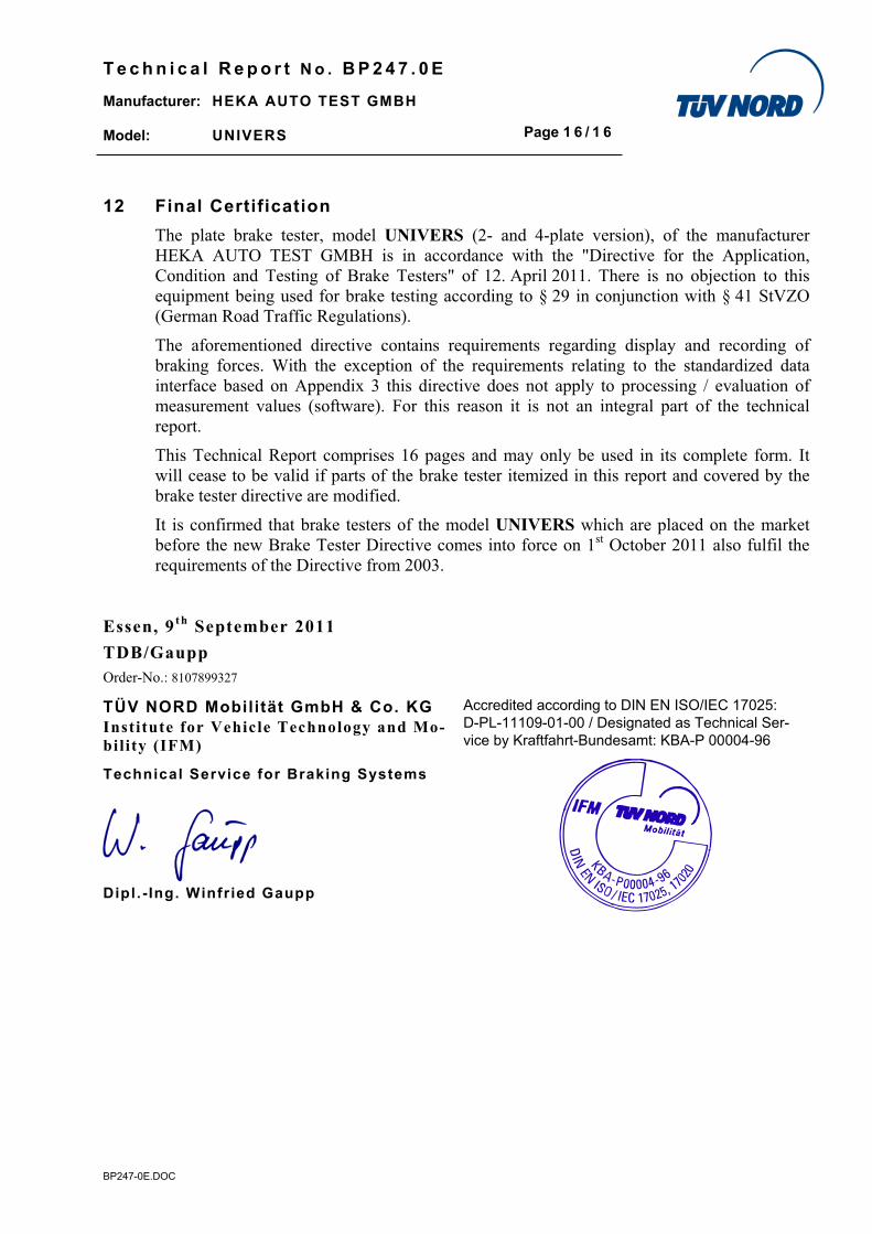
12 Final Certification
The plate brake tester, model UNIVERS (2- and 4-plate version), of the manufacturer
HEKA AUTO TEST GMBH is in accordance with the "Directive for the Application,
Condition and Testing of Brake Testers" of 12. April 2011. There is no objection to this
equipment being used for brake testing according to § 29 in conjunction with § 41 StVZO
(German Road Traffic Regulations).
The aforementioned directive contains requirements regarding display and recording of
braking forces. With the exception of the requirements relating to the standardized data
interface based on Appendix 3 this directive does not apply to processing / evaluation of
measurement values (software). For this reason it is not an integral part of the technical
report.
This Technical Report comprises 16 pages and may only be used in its complete form. It
will cease to be valid if parts of the brake tester itemized in this report and covered by the
brake tester directive are modified.
It is confirmed that brake testers of the model UNIVERS which are placed on the market
before the new Brake Tester Directive comes into force on 1st October 2011 also fulfil the
requirements of the Directive from 2003.
Essen, 9 t h September 2011
TDB/Gaupp
Order-No.: 8107899327
TÜV NORD Mobilität GmbH & Co. KGInstitute for Vehicle Technology and Mo-bility (IFM)
Accredited according to DIN EN ISO/IEC 17025:
D-PL-11109-01-00 / Designated as Technical Ser-
vice by Kraftfahrt-Bundesamt: KBA-P 00004-96
Technical Service for Braking Systems
Dipl . - Ing. Winfried Gaupp