heatlink plumbing, heating, & panels product catalog ...€¦ · plumbing, heating, &...
TRANSCRIPT

®
Heat Link
Plumbing, Heating, & PanelsProduct Catalog / Price List
Eff ective July 1, 2014
2014USA

®
Heat Link
About Us
HeatLink is a multi-system supplier of potable water and radiant hydronic heating/cooling and snow melt systems. For over 20 years we have created comfortable and effi cient heating, cooling and plumbing systems for residential and commercial construction.
HeatLink’s radiant heating systems create a comfortable and energy effi cient environment for living. Our snow melt systems create safer public and private spaces that reduce liability for property owners, reduce maintenance, and ensure accessibility. Our well engineered plumbing systems provide peace of mind for property owners through extensive warranty protection, and enable quick and effi cient installations for builders and contractors.
History
HeatLink began as a family owned business developed to service a number of industries including HVAC. The company grew to meet the needs of builders, contractors, and architects and began designing and installing radiant heating systems in 1985. Since 1985 HeatLink has grown into an industry leading designer and manufacturer of radiant heating, cooling, and potable water systems.
HeatLink has developed and manufactured a long list of industry fi rsts such as the “TwistSeal” tool-less manifold in 1996. The company began manufacturing PEX-a tubing in 1998 and now supplies the highest quality PEX-a systems to customers throughout North America and parts of Europe and Asia.
HeatLink works with a network of experienced and successful partner agencies to meet the design, system installation and training needs of the construction industry, designers, and architects.
Solutions
HeatLink in an industry leader in providing a broad range of potable water and radiant heating/cooling and snow melt systems for customers throughout the world. Our focus from our inception remains on creating well engineered and energy effi cient solutions that are easy to install and last a lifetime.
Company Description
Our innovative plumbing and heating systems help provide a comfortable and worry free environment for people in residential and commercial work and living spaces. We continue to design quiet and energy effi cient heating and potable water systems that are easy to install and last a lifetime. HeatLink was built on a strong family work ethic and a value system that remain the foundation for our continuing growth and industry leadership role.
®
Heat Link
2
www.heatlink.com
Table of Contents
Discounts Structure & Shipping Allowances ........................................ 3
Terms and Conditions of Sale, Delivery and Payment....................... 4
HeatingPEX Heating Tubing with O
2 Barrier ......................................................... 5
PEX Heating Tubing Non Barrier ............................................................... 7
TwistSeal® (55 mm) Manifold Assembly Kits......................................... 9
TwistSeal® (55 mm) Manifold Modules .................................................10
TwistSeal® Mini (40 mm) Manifold Assembly Kit...............................12
TwistSeal® Mini (40 mm) Manifold Modules .......................................13
TwistSeal® Manifold Accessories .............................................................14
1-1⁄4” Stainless Steel Manifolds ..................................................................16
1-1⁄4” Stainless Steel Manifold Accessories ............................................17
2” Stainless Steel Manifolds .......................................................................19
2” Stainless Steel Manifold Accessories ................................................20
Manifold Housings .......................................................................................22
PEX Compression Adapters ......................................................................23
2-way Injection Mixing ...............................................................................25
3-way Compact Mixing System ...............................................................26
3-way Mixing System ..................................................................................27
4-way Mixing System ..................................................................................28
Mixing Valves .................................................................................................29
Valves ................................................................................................................32
Mixing Valve Motors ....................................................................................35
Thermostatic Heads .....................................................................................36
Actuators .........................................................................................................37
Thermostats ....................................................................................................40
24V AC Relay ...................................................................................................42
StatLink® Modules ........................................................................................43
Controls ............................................................................................................44
Sensors .............................................................................................................45
“Wet” System ..................................................................................................48
DryAbove™ System ......................................................................................51
DryBelow™ System .......................................................................................52
Floor Heating Accessories .........................................................................53
Chemicals ........................................................................................................56
Water Testing ..................................................................................................57
Sidestream Filter ...........................................................................................58
Mechanical Room in a Box (Panels)Introduction ...................................................................................................60
System Panel Selection ..............................................................................61
ECO - ECO Boiler Panels ..............................................................................62
V100 - V100 Boiler Panels ...........................................................................64
CAD - CAD Boiler Panels .............................................................................66
ELBP - Electric Boiler Panels ......................................................................68
TMP – 3-Way Mixing Panels ......................................................................72
TWH – Tankless Water Heater Panels .....................................................80
HEP – Isolation Heat Exchanger Panels ................................................86
WHP - Water Heater Panels .......................................................................90
CDP – 2-Temperature Combi DHW Panels ..........................................92
SOL - Solar Heat Exchanger Panel ..........................................................98
SSM - Stainless Steel Manifold Panels ................................................ 100
SSP - Stainless Steel Manifold Pump Panels ..................................... 102
SSTS - Stainless Steel Manifold Small Mixing Panels .................... 104
SSTL - Stainless Steel Manifold Large Mixing Panels .................... 106
SMP – Snow Melt Panels ......................................................................... 108
Snow Melt Panel Options & Accessories ........................................... 116
PlumbingPureLink® Potable Water PEX-a Tubing .............................................. 117
PureLink® Pipe-in-Pipe ............................................................................. 121
EasyFit™ Manifold ...................................................................................... 122
HPP Multiport Tees .................................................................................... 125
SS Press Sleeves .......................................................................................... 126
PEX Insert Couplings ................................................................................ 128
PEX Insert Elbows ...................................................................................... 129
PEX Insert Threaded Elbows .................................................................. 130
PEX Insert FNPT Adapters ....................................................................... 131
PEX Insert Fixture Adapters ................................................................... 132
PEX Insert MNPT Adapters ..................................................................... 133
PEX Insert Sweat Adapters ..................................................................... 134
PEX Insert Tees ............................................................................................ 134
PEX Insert Plugs ......................................................................................... 137
Ball Valves ..................................................................................................... 138
Stubout Elbows .......................................................................................... 140
Accessories, Tools, and PartsAccessories ................................................................................................... 141
Tools ............................................................................................................... 142
Parts ................................................................................................................ 150
Listing by Stk#Listing by Stk# ............................................................................................. 160
USA - July 1, 2014
®
Heat Link
3
www.heatlink.com
Discounts Structure & Shipping AllowancesUSA - July 1, 2014
Please note: this price list supersedes all previous price lists.
For your discounts please contact your local sales representative.
Shipping Allowances
• Prices and specifi cations are subject to change without notice.
• Products shipped in multiples of quantity listed only.
Standard shipping times: 3 days from confi rmed order (or less).
D/C pickups: 3 days from confi rmed order (or less), scheduled with local HeatLink shipping department.
Minimum order value: $100.00 net
Rush orders: Same day shipment if order confi rmed by 11AM.
Next day if order confi rmed after 11AM.
Next day freight charges applicable.
Rush charges may apply.
Backorders: Shipped with subsequent order to stocking distributor (if no subsequent order is in place, product will be
shipped freight prepaid ground n/c).
Prepaid freight: $ 3,500 net minimum order without PEX straight lengths.
$ 5,000 net minimum order if ordering PEX straight lengths.
Subject to change without notice.
Fuel surcharge: May apply on prepaid orders. Rates are subject to change without notice.
®
Heat Link
4
www.heatlink.com
Terms and Conditions of Sale, Delivery and Payment
General Provisions1. (a) This agreement, performances of contract and quotations are made exclusively
upon the terms and conditions set out below. Alterations or deviations from the provisions herein contained shall not be binding upon HeatLink Group Inc. unless confi rmed in writing.
(b) The Purchaser hereby accepts the terms and conditions herein contained in their entirety. Stipulations of terms and conditions contrary to the provi-sion hereof according to the Purchaser’s business or purchasing practices, invoicing, manner of payment or custom of the trade are hereby specifi cally agreed to be inapplicable to this agreement.
(c) In the event that any one or more of the provisions herein contained shall become or be deemed to be invalid, illegal or unenforceable by operation of law, the validity, legality and enforceability of the remaining provisions or any part thereof shall not in any manner be affected or impaired thereby. In place and stead of any such invalid, illegal or unenforceable provisions of any part thereof, the parties hereto shall be deemed to have agreed upon terms and conditions, which, as far as permitted by law, express the intent and purpose of the within terms and conditions.
Plans and Specifi cations2. Drawings, specifi cations and technical data appended to or forming part of the
agreement shall at all times remain the property of HeatLink Group Inc., with all rights reserved and shall not be provided, submitted or disclosed to third parties without the express written consent of HeatLink Group Inc. Changes, alterations, deletions or additions thereto shall not be binding upon HeatLink Group Inc. unless confi rmed in writing.
Prices and Quotations3. (a) HeatLink Group Inc. hereby specifi cally reserves the right to change, alter,
amend or revoke quotations but the same shall become binding and irrevo-cable only upon written acceptance by both HeatLink Group Inc. and the Purchaser or upon delivery to and acceptance of goods by the Purchaser.
(b) Prices are, save and except as otherwise agreed upon, as at HeatLink Group Inc.’s location in Calgary, Alberta, Canada, exclusive of cost of packaging, crating, freight or shipping, federal, provincial or local rates, tariffs and taxes in effect on date of delivery.
(c) All contract prices are guaranteed for thirty (30) days from date of contract. Cost increases 30 days after contract date, including but not limited to cost increases of materials, wages, fuel, transportation or energy charges and increases in applicable federal, provincial and local rates, tariffs or taxes shall be added to the contract price and form part thereof as if originally agreed upon.
(d) Contracts for delivery of goods or performance of services without specifi c agreement as to price shall be subject to the price or prices in effect on the date of delivery of goods.
Terms of Payment4. (a) Save and except as otherwise specifi cally agreed upon in writing, all invoices
or accounts, as the case may be, shall become due and payable in full without deduction whatsoever thirty (30) days after invoice or account date.
(b) Holdbacks or deductions of any kind whatsoever without prior written authori-zation from HeatLink Group Inc. are expressly prohibited.
(c) Discounts, if any, shall be calculated on the cost of goods as per invoice, exclusive of cost of packaging, crating, freight or shipping, federal, provincial or local rates, tariffs or taxes, where applicable, or other costs or surcharges beyond control of HeatLink Group Inc.
(d) Payment will be in a form agreed to and acceptable by HeatLink Group Inc. All costs for dishonour, presentment for payment or collection shall be at the expense of the Purchaser and Payor. All payments by cheque, whether certifi ed or uncertifi ed, shall be deemed as having been received on the date of acceptance for payment of the said cheque or cheques by the Purchaser’s or Payor’s bank, trust company or fi nancial institution upon whose account the cheque has been issued.
(e) Payments received shall be applied fi rstly to designated accounts, dishonour or collection; secondly, to outstanding interest charges on the oldest accounts; and, thirdly, the balance, if any, of any payment shall be applied to the most recent accounts, outstanding balance or balances. If an account is past due at the time of payment, then application of received funds will be in the order best interest to HeatLink Group Inc.
(f) In the event the Purchaser defaults in payment or causes a cheque, bank draft or money order to be dishonoured or stops payment thereon, or HeatLink Group Inc. shall deem the Purchaser insecure, all accounts shall forthwith become due and payable notwithstanding any agreement as to credit or periodic payment.
(g) Overdue accounts shall bear interest at the rate stated on the face of the invoice or (if no rate is displayed on the invoice), 2% calculated and com-pounded monthly.
Reservation of Title and Property5. (a) It is hereby expressly agreed that all goods shall remain the exclusive property
of HeatLink Group Inc. and title shall not pass until payment in full of all invoices or accounts rendered, including cost of goods, packaging, carting, shipping or freight charges, federal, provincial or local taxes, rates and tariffs, insurance, extras to contract, interest charges, exchange or collection expenses and other sums or charges applicable has been received pursuant to the terms and conditions herein contained.
(b) Goods delivered shall not, in any event, become part of real estate and the Purchaser shall at all times take or initiate all steps necessary to preserve HeatLink Group Inc.’s right, title and property to such goods.
(c) The Purchaser shall not permit any goods sold or delivered by HeatLink Group Inc. to be pledged or encumbered without express written consent from HeatLink Group Inc. In the event of seizure by third parties, the Purchaser shall forthwith disclose HeatLink Group Inc.’s reservation of title, right and property to such goods and shall forthwith notify HeatLink Group Inc. of such seizure and shall assist HeatLink Group Inc. at the Purchaser’s cost in the preservation and enforcement of HeatLink Group Inc.’s right, title and property to the said goods.
(d) In the event of breach of contract by the Purchaser of the terms or condi-tions herein contained and, in particular, default of payment of invoices as hereinbefore provided, HeatLink Group Inc. shall be entitled, without prior notice, to demand delivery up of goods sold and delivered and to seize the same wherever the same may be located at any time of day or night or to cause its agents, workmen or bailiffs to seize the same, wherever the same may be located at any time of day or night notwithstanding the goods may be in possession of a subsequent purchaser or user.
(e) Seizure of goods by HeatLink Group Inc. shall not be deemed to constitute termination of contract or contractual rights and obligations as between HeatLink Group Inc. and the Purchaser.
Delivery of Goods6. (a) HeatLink Group Inc. shall at all times use its best efforts to maintain the
delivery dates agreed upon. The delivery date or period shall be deemed to have been maintained or complied with in all events, cases or situations where the goods to be delivered leave HeatLink Group Inc.’s premises on or before such date, before the expiry of such period or the Purchaser is notifi ed before the applicable date that the goods are ready for shipment.
(b) Delivery dates or periods shall be extended by reason of delays causes by labour shortages, strikes or lockouts or other circumstances beyond the rea-sonable control of HeatLink Group Inc. Any delay or postponement of delivery to HeatLink Group Inc. of goods and supplies by its suppliers, subcontractors or co-contractors caused by strike, lockout, labour shortage or unrest or other causes beyond the reasonable control of HeatLink Group Inc., its suppliers, subcontractors or co-contractors shall in like manner extend delivery dates and periods as if the same applied to HeatLink Group Inc.
(c) In the event of delay in delivery of goods caused by the Purchaser for any reason whatsoever, HeatLink Group Inc. shall be entitled to charge the cost of storage calculated at the rate of one half (1/2%) percent per month upon the cost of goods, such calculation commencing one month after delivery of Notice of Readiness for shipment and continuing for each and every month or part thereof thereafter until the goods can be delivered to the Purchaser.
Risk of Property7. (a) Commencing on the date of delivery of goods for shipment or transport to
the Purchaser, the said goods or any part thereof shall be at the risk of the Purchaser.
(b) Any goods or part thereof delivered for shipment or transport to the Purchaser from the factory Calgary, Alberta, or elsewhere, including goods with unes-sential or minor defects, shall be deemed to have been accepted by the Purchaser without recourse.
(c) Defi ciencies or defects in goods or part thereof shipped or the shipment of the wrong goods, or part or part thereof, shall be endorsed upon the bill of lading and shall be communicated to HeatLink Group Inc. in writing within three (3) business days of arrival at destination. Failing such notifi cation, the Purchaser shall be deemed to have accepted the goods without recourse.
Return of Goods8. (a) All or any goods returned without prior authorization by HeatLink Group Inc.
shall not be accepted. (b) If returns are authorized by HeatLink Group Inc., goods will be accepted as
follows: (i) New and unused goods upon authorization by HeatLink Group Inc.,
with freight to be prepaid plus 25% restocking charge. (ii) Outdated goods, with freight prepaid plus 25% restocking charge plus
refurbishing costs.(c) In all cases, unless express written authorization is given, goods must be
returned in condition for immediate resale. If goods and packaging are not in condition for immediate resale, HeatLink Group Inc. reserves the right to refuse to accept the returned goods, charge additionally for refurbishing goods or packaging, or any other agreed to return remedy negotiated with the customer. In all cases, HeatLink Group Inc. will have the fi nal approval as to whether returned goods are accepted or unaccepted under any of the above remedies.
Insurance9. During the period commencing with the delivery of goods for shipment or
transport to the Purchaser and ending upon receipt of payment in full for the said goods pursuant to the terms and conditions hereof, the Purchaser shall insure the said goods in the joint names of HeatLink Group Inc. and the Purchaser against all risk of loss or damage howsoever caused.
Applicable Law10. All disputes, claims or demands arising from or relating to warranties, guar-
antees, representations authorized and published by HeatLink Group Inc., and from the terms and conditions herein contained and all claims, demands, rights or liabilities arising from such warranties, guarantees, representations or terms and conditions shall be determined in accordance with the laws of the Province of Alberta, Canada.
USA - July 1, 2014
5
®
Heat Linkwww.heatlink.com
Ra
dia
nt Hea
ting & Cooling
PEX Heating Tubing with O2 Barrier
PEX Tubing Coils with O2 Barrier
94000 Series
High molecular cross-linked poly eth yl ene (PEX) with minimum bend ing radii of
6× the diameter at 68°F (20°C). Maximum op er at ing tem per a ture: 180°F @ 100 PSI
(82°C @ 690 kPa). Covered by a twen ty-fi ve year manufacturer’s limited warranty.
Comes with oxygen diff u sion barrier which pre vents ox y gen from entering the
heat ing system through the tubing wall.
* Check with your local representative for availability.
USA - July 1, 2014
Stk# Description Pkg Qty Carton Qty Unit List Price / Unit
943123⁄8" 300ft O
2 Barrier HeatLink® UV Stabilized PEX-a
Tubing1 40 coil
942051⁄2" 250ft O
2 Barrier HeatLink® UV Stabilized PEX-a
Tubing1 40 coil
943051⁄2" 300ft O
2 Barrier HeatLink® UV Stabilized PEX-a
Tubing1 40 coil
945051⁄2" 500ft O
2 Barrier HeatLink® UV Stabilized PEX-a
Tubing1 20 coil
941051⁄2" 1000ft O
2 Barrier HeatLink® UV Stabilized PEX-a
Tubing1 16 coil
943195⁄8" 300ft O
2 Barrier HeatLink® UV Stabilized PEX-a
Tubing1 20 coil
945195⁄8" 500ft O
2 Barrier HeatLink® UV Stabilized PEX-a
Tubing1 16 coil
941195⁄8" 1000ft O
2 Barrier HeatLink® UV Stabilized PEX-a
Tubing1 12 coil
Special Order* 94922
3⁄4" 100ft O2 Barrier HeatLink® UV Stabilized PEX-a
Tubing3 48 coil
943223⁄4" 300ft O
2 Barrier HeatLink® UV Stabilized PEX-a
Tubing1 16 coil
945223⁄4" 500ft O
2 Barrier HeatLink® UV Stabilized PEX-a
Tubing1 12 coil
941223⁄4" 1000ft O
2 Barrier HeatLink® UV Stabilized PEX-a
Tubing1 5 coil
94128 1" 100ft O2 Barrier HeatLink® UV Stabilized PEX-a Tubing 1 19 coil
94528 1" 500ft O2 Barrier HeatLink® UV Stabilized PEX-a Tubing 1 5 coil
941351-1⁄4" 100ft O
2 Barrier HeatLink® UV Stabilized PEX-a
Tubing1 14 coil
943351-1⁄4" 300ft O
2 Barrier HeatLink® UV Stabilized PEX-a
Tubing1 5 coil
941411-1⁄2" 100ft O
2 Barrier HeatLink® UV Stabilized PEX-a
Tubing1 5 coil
943411-1⁄2" 300ft O
2 Barrier HeatLink® UV Stabilized PEX-a
Tubing1 5 coil
Stk# Description Pkg Qty Skid Qty Unit List Price / Unit
6
®
Heat Linkwww.heatlink.com
Ra
dia
nt H
eati
ng &
Coo
ling
PEX Heating Tubing with O2 Barrier
PEX Tubing Straight Lengths with O2 Barrier
94000 Series
High molecular cross-linked poly eth yl ene (PEX) with minimum bend ing radii of
6× the diameter at 68°F (20°C). Maximum op er at ing tem per a ture: 180°F @ 100 PSI
(82°C @ 690 kPa). Covered by a twen ty-fi ve year manufacturer’s limited warranty.
Comes with oxygen diff u sion barrier which pre vents ox y gen from entering the
heat ing system through the tubing wall.
* Lead time may vary. Call to confi rm time line.
HeatLink® O2 Barrier Pipe-in-Pipe
94000 Sheathed Series
PEX-a carrier tubing specifi ed on previous pages. The fl exible, impact resistant red PE sheath designed as a raceway for electrical
installations provides mechanical and UV protection to the PEX-a carrier tubing. The sheath allows for easy replacement of the PEX-a carrier
tubing if needed.
Minimum bending radius @ 68˚F (20˚C) for: 1⁄2" = 3" (77 mm)
PE sheath is rated to UL94HB “Tests for Flammability of Plastic Materials.”
Corrugated sheath outside diameter for: 1⁄2" = 1515⁄1616" (23 mm)
USA - July 1, 2014
Stk# Description Pkg Qty Carton Qty Unit List Price / Unit
942223⁄4" 10×20ft O
2 Barrier HeatLink® UV Stabilized PEX-a
Tubing1 20 bundle
942281" 5×20ft O
2 Barrier HeatLink® UV Stabilized PEX-a
Tubing1 20 bundle
942351-1⁄4" 5×20ft O
2 Barrier HeatLink® UV Stabilized PEX-a
Tubing1 20 bundle
942411-1⁄2" 5×20ft O
2 Barrier HeatLink® UV Stabilized PEX-a
Tubing1 20 bundle
Stk# Description Pkg Qty Carton Qty Unit List Price / Unit
New! 94305rs 1⁄2" 300' O2 Barrier HeatLink® Pipe-in-Pipe Red Sheath 1 14 coil
Special Order* 94322rs 3⁄4" 300' O
2 Barrier HeatLink® Pipe-in-Pipe Red Sheath 1 9 coil
Stk# Description Pkg Qty Master Bag Unit List Price / Unit
Stk# Description Pkg Qty Skid Qty Unit List Price / Unit
7
®
Heat Linkwww.heatlink.com
Ra
dia
nt Hea
ting & Cooling
Non Barrier PEX Tubing Coils
20000 & 99000 Series
High molecular cross-linked poly eth yl ene (PEX) with minimum bend ing radii of
6× the diameter at 68°F (20°C). Maximum operating tem per a ture: 180°F @ 100 PSI
(82°C @ 690 kPa). Covered by a twen ty-fi ve year manufacturer’s limited warranty.
PEX Heating Tubing Non BarrierUSA - July 1, 2014
Stk# Description Pkg Qty Carton Qty Unit List Price / Unit
WSL 992123⁄8" 200ft Non-Barrier HeatLink® UV Stabilized PEX-a
Tubing1 coil
20305 1⁄2" 300ft Blue PureLink® Plus UV Stabilized PEX-a Tubing 1 32 coil
20505 1⁄2" 500ft Blue PureLink® Plus UV Stabilized PEX-a Tubing 1 20 coil
209051⁄2" 1000ft Blue PureLink® Plus UV Stabilized PEX-a
Tubing1 14 coil
20322 3⁄4" 300ft Blue PureLink® Plus UV Stabilized PEX-a Tubing 1 14 coil
20522 3⁄4" 500ft Blue PureLink® Plus UV Stabilized PEX-a Tubing 1 9 coil
209223⁄4" 1000ft Blue PureLink® Plus UV Stabilized PEX-a
Tubing1 5 coil
20128 1" 100ft Blue PureLink® Plus UV Stabilized PEX-a Tubing 1 19 coil
20328 1" 300ft Blue PureLink® Plus UV Stabilized PEX-a Tubing 1 9 coil
Stk# Description Pkg Qty Skid Qty Unit List Price / Unit
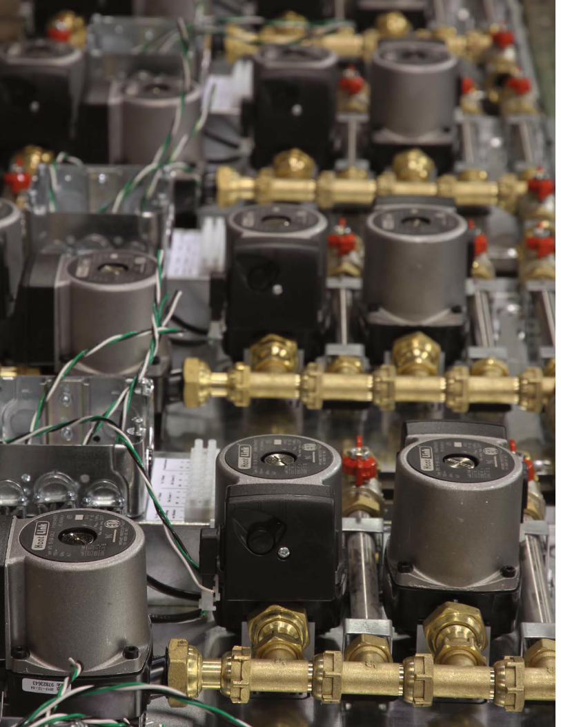
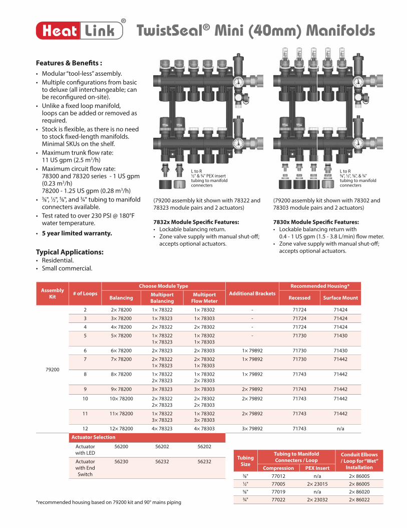
TwistSeal® (55 mm) Manifolds®
Heat Link
Features & Benefi ts :
• Modular “tool-less” assembly.
• Multiple confi gurations from basic to deluxe (all interchangeable; can be reconfi gured on-site).
• Unlike a fi xed loop manifold, loops can be added or removed as required.
• Stock is fl exible, as there is no need to stock fi xed-length manifolds. Minimal SKUs on the shelf.
• Balancing return.
• Zone valve supply with manual shut-off ; accepts optional actuators.
• Max. trunk fl ow rate:79400 kit - 18 US gpm (4.1 m3/h)79402 kit - 22 US gpm (5 m3/h)
• Max. circuit fl ow rate:2.5 US gpm (0.57 m3/h)
• 3⁄8", 1⁄2", 5⁄8", and 3⁄4" tubing to manifold connecters available.
• Test rated to over 230 PSI @ 180°F water temperature.
• 5 year limited warranty.
(79402 assembly kit shown with 4× 78400
module pairs and 2 actuators)
(79400 assembly kit shown with 4× 78400
module pairs and 2 actuators)
Assembly
Kit# of Loops
Choose
Module Type Additional BracketsRecommended Housing*
Balancing Recessed** Surface Mount
79400
or
79401
or
79402
2 2× 78400 - 71724 71424
3 3× 78400 - 71724 71424
4 4× 78400 - 71730 71430
5 5× 78400 - 71730 71430
6 6× 78400 1× 79991 71743 71430
7 7× 78400 1× 79991 71743 71442
8 8× 78400 1× 79991 71743 71442
9 9× 78400 2× 79991 71743 71442
10 10× 78400 2× 79991 71743 71442
11 11× 78400 2× 79991 n/a n/a
12 12× 78400 3× 79991 n/a n/a
Actuator Selection
Actuator
with LED
56200
Actuator
with End
Switch
56230 Tubing Size
Tubing to Manifold Connecters
/ Loop Conduit Elbows / Loop
for “Wet” InstallationCompression PEX Insert
3⁄8" 77012 n/a 2× 86005
1⁄2" 77005 2× 23015 2× 86005
5⁄8" 77019 n/a 2× 86020
3⁄4" 77022 2× 23032 2× 86022
* Recommended housing based on 79402 kit and 90° mains piping.
** Thermometers must be removed.
L to R3⁄8", 1⁄2", 5⁄8", & 3⁄4" tubing to manifold connecters
L to R1⁄2" & 3⁄4" PEX insert tubing to manifold connecters
Typical Applications: • Commercial.
• Snow melting.
9
®
Heat Linkwww.heatlink.com
Ra
dia
nt Hea
ting & Cooling
TwistSeal® (55 mm) Manifold Assembly Kits
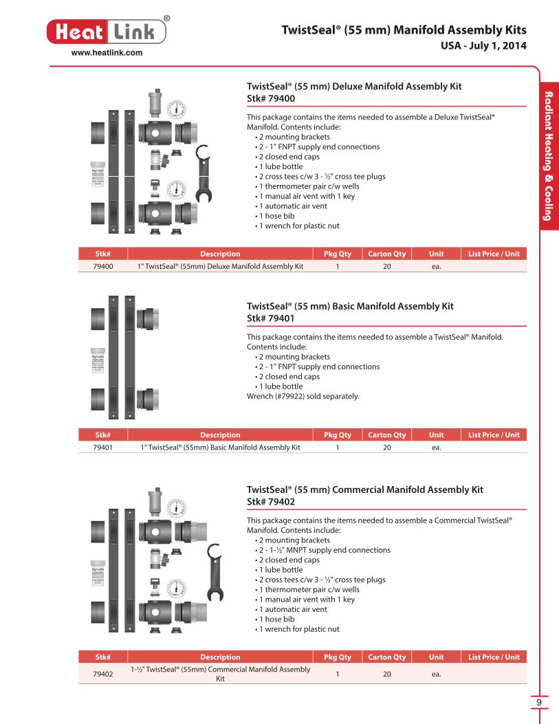
TwistSeal® (55 mm) Commercial Manifold Assembly Kit
Stk# 79402
This package contains the items need ed to assemble a Com mer cial TwistSeal®
Manifold. Contents include:
• 2 mounting brackets
• 2 - 1-1⁄2" MNPT supply end connections
• 2 closed end caps
• 1 lube bottle
• 2 cross tees c/w 3 - 1⁄2" cross tee plugs
• 1 thermometer pair c/w wells
• 1 manual air vent with 1 key
• 1 au to mat ic air vent
• 1 hose bib
• 1 wrench for plastic nut
TwistSeal® (55 mm) Deluxe Manifold Assembly Kit
Stk# 79400
This package contains the items need ed to assemble a Deluxe TwistSeal®
Manifold. Contents include:
• 2 mounting brackets
• 2 - 1" FNPT supply end connections
• 2 closed end caps
• 1 lube bottle
• 2 cross tees c/w 3 - 1⁄2" cross tee plugs
• 1 thermometer pair c/w wells
• 1 manual air vent with 1 key
• 1 au to mat ic air vent
• 1 hose bib
• 1 wrench for plastic nut
TwistSeal® (55 mm) Basic Manifold Assembly Kit
Stk# 79401
This package contains the items need ed to assemble a TwistSeal® Man i fold.
Contents include:
• 2 mounting brackets
• 2 - 1" FNPT supply end connections
• 2 closed end caps
• 1 lube bottle
Wrench (#79922) sold separately.
USA - July 1, 2014
Stk# Description Pkg Qty Carton Qty Unit List Price / Unit
79400 1" TwistSeal® (55mm) Deluxe Manifold Assembly Kit 1 20 ea.
Stk# Description Pkg Qty Carton Qty Unit List Price / Unit
79401 1" TwistSeal® (55mm) Basic Manifold Assembly Kit 1 20 ea.
Stk# Description Pkg Qty Carton Qty Unit List Price / Unit
794021-1⁄2" TwistSeal® (55mm) Commercial Manifold Assembly
Kit1 20 ea.
10
®
Heat Linkwww.heatlink.com
Ra
dia
nt H
eati
ng &
Coo
ling
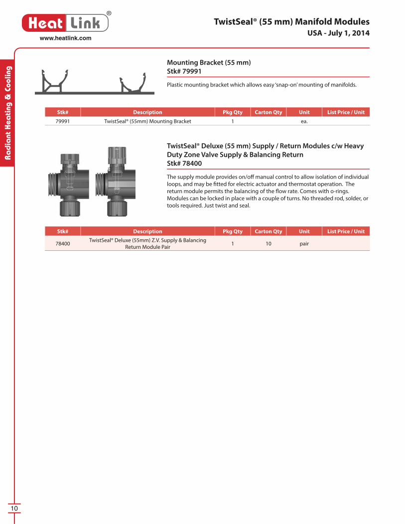
TwistSeal® Deluxe (55 mm) Supply / Return Modules c/w Heavy
Duty Zone Valve Supply & Balancing Return
Stk# 78400
The supply module provides on/off manual control to allow iso la tion of individual
loops, and may be fi tted for electric actuator and ther mo stat op er a tion. The
return mod ule permits the bal anc ing of the fl ow rate. Comes with o-rings.
Modules can be locked in place with a couple of turns. No threaded rod, solder, or
tools required. Just twist and seal.
Mounting Bracket (55 mm)
Stk# 79991
Plastic mounting bracket which al lows easy ‘snap-on’ mount ing of manifolds.
TwistSeal® (55 mm) Manifold ModulesUSA - July 1, 2014
Stk# Description Pkg Qty Carton Qty Unit List Price / Unit
79991 TwistSeal® (55mm) Mounting Bracket 1 ea.
Stk# Description Pkg Qty Carton Qty Unit List Price / Unit
78400TwistSeal® Deluxe (55mm) Z.V. Supply & Balancing
Return Module Pair1 10 pair
TwistSeal® Mini (40mm) Manifolds®
Heat Link
(79200 assembly kit shown with 78322 and
78323 module pairs and 2 actuators)
7832x Module Specifi c Features:
• Lockable balancing return.
• Zone valve supply with manual shut-off ;
accepts optional actuators.
(79200 assembly kit shown with 78302 and
78303 module pairs and 2 actuators)
7830x Module Specifi c Features:
• Lockable balancing return with
0.4 - 1 US gpm (1.5 - 3.8 L/min) fl ow meter.
• Zone valve supply with manual shut-off ;
accepts optional actuators.
L to R3⁄8", 1⁄2", 5⁄8", & 3⁄4" tubing to manifold connecters
L to R1⁄2" & 3⁄4" PEX insert tubing to manifold connecters
Assembly
Kit# of Loops
Choose Module Type
Additional Brackets
Recommended Housing*
BalancingMultiport
Balancing
Multiport
Flow MeterRecessed Surface Mount
79200
2 2× 78200 1× 78322 1× 78302 - 71724 71424
3 3× 78200 1× 78323 1× 78303 - 71724 71424
4 4× 78200 2× 78322 2× 78302 - 71724 71424
5 5× 78200 1× 78322
1× 78323
1× 78302
1× 78303
- 71730 71430
6 6× 78200 2× 78323 2× 78303 1× 79892 71730 71430
7 7× 78200 2× 78322
1× 78323
2× 78302
1× 78303
1× 79892 71730 71442
8 8× 78200 1× 78322
2× 78323
1× 78302
2× 78303
1× 79892 71743 71442
9 9× 78200 3× 78323 3× 78303 2× 79892 71743 71442
10 10× 78200 2× 78322
2× 78323
2× 78302
2× 78303
2× 79892 71743 71442
11 11× 78200 1× 78322
3× 78323
1× 78302
3× 78303
2× 79892 71743 71442
12 12× 78200 4× 78323 4× 78303 3× 79892 71743 n/a
Actuator Selection
Actuator
with LED
56200 56202 56202
Actuator
with End
Switch
56230 56232 56232
Features & Benefi ts :
• Modular “tool-less” assembly.
• Multiple confi gurations from basic to deluxe (all interchangeable; can be reconfi gured on-site).
• Unlike a fi xed loop manifold, loops can be added or removed as required.
• Stock is fl exible, as there is no need to stock fi xed-length manifolds. Minimal SKUs on the shelf.
• Maximum trunk fl ow rate:11 US gpm (2.5 m3/h)
• Maximum circuit fl ow rate:78300 and 78320 series - 1 US gpm (0.23 m3/h) 78200 - 1.25 US gpm (0.28 m3/h)
• 3⁄8", 1⁄2", 5⁄8", and 3⁄4" tubing to manifold connecters available.
• Test rated to over 230 PSI @ 180°F water temperature.
• 5 year limited warranty.
Typical Applications: • Residential.
• Small commercial.
*recommended housing based on 79200 kit and 90° mains piping
Tubing
Size
Tubing to Manifold
Connecters / LoopConduit Elbows
/ Loop for “Wet”
InstallationCompression PEX Insert3⁄8" 77012 n/a 2× 860051⁄2" 77005 2× 23015 2× 860055⁄8" 77019 n/a 2× 860203⁄4" 77022 2× 23032 2× 86022
12
®
Heat Linkwww.heatlink.com
Ra
dia
nt H
eati
ng &
Coo
ling
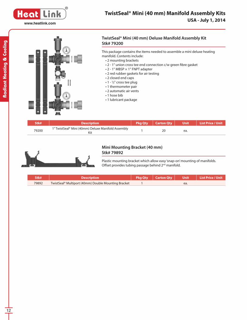
Mini Mounting Bracket (40 mm)
Stk# 79892
Plastic mounting bracket which allow easy ‘snap-on’ mounting of manifolds.
Off set provides tubing passage behind 2nd manifold.
TwistSeal® Mini (40 mm) Manifold Assembly Kits
TwistSeal® Mini (40 mm) Deluxe Manifold Assembly Kit
Stk# 79200
This package contains the items needed to assemble a mini deluxe heating
manifold. Contents include:
• 2 mounting brackets
• 2 - 1" union cross tee end connection c/w green fi bre gasket
• 2 - 1" MBSP × 1" FNPT adapter
• 2 red rubber gaskets for air testing
• 2 closed end caps
• 1 - 1⁄2" cross tee plug
• 1 thermometer pair
• 2 automatic air vents
• 1 hose bib
• 1 lubricant package
USA - July 1, 2014
Stk# Description Pkg Qty Carton Qty Unit List Price / Unit
792001" TwistSeal® Mini (40mm) Deluxe Manifold Assembly
Kit1 20 ea.
Stk# Description Pkg Qty Carton Qty Unit List Price / Unit
79892 TwistSeal® Multiport (40mm) Double Mounting Bracket 1 ea.
13
®
Heat Linkwww.heatlink.com
Ra
dia
nt Hea
ting & Cooling
TwistSeal® Mini (40 mm) Manifold Modules
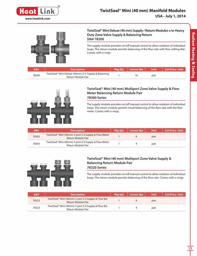
TwistSeal® Mini Deluxe (40 mm) Supply / Return Modules c/w Heavy
Duty Zone Valve Supply & Balancing Return
Stk# 78200
The supply module provides on/off manual control to allow isolation of individual
loops. The return module permits balancing of the fl ow rate with fl ow setting dial.
Comes with o-rings.
TwistSeal® Mini (40 mm) Multiport Zone Valve Supply & Flow
Meter Balancing Return Module Pair
78300 Series
The supply module provides on/off manual control to allow isolation of individual
loops. The return module permits visual balancing of the fl ow rate with the fl ow
meter. Comes with o-rings.
TwistSeal® Mini (40 mm) Multiport Zone Valve Supply &
Balancing Return Module Pair
78320 Series
The supply module provides on/off manual control to allow isolation of individual
loops. The return module permits balancing of the fl ow rate. Comes with o-rings.
USA - July 1, 2014
Stk# Description Pkg Qty Carton Qty Unit List Price / Unit
78200TwistSeal® Mini Deluxe (40mm) Z.V. Supply & Balancing
Return Module Pair1 10 pair
Stk# Description Pkg Qty Carton Qty Unit List Price / Unit
78302TwistSeal® Mini (40mm) 2-port Z.V.Supply & Flow Meter
Return Module Pair1 6 pair
78303TwistSeal® Mini (40mm) 3-port Z.V.Supply & Flow Meter
Return Module Pair1 4 pair
Stk# Description Pkg Qty Carton Qty Unit List Price / Unit
78322TwistSeal® Mini (40mm) 2-port Z.V.Supply & Flow Bal.
Return Module Pair1 6 pair
78323TwistSeal® Mini (40mm) 3-port Z.V.Supply & Flow Bal.
Return Module Pair1 4 pair
14
®
Heat Linkwww.heatlink.com
Ra
dia
nt H
eati
ng &
Coo
ling
TwistSeal® Manifold Accessories
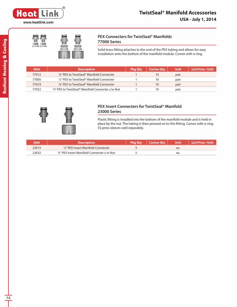
PEX Connecters for TwistSeal® Manifolds
77000 Series
Solid brass fi tting attaches to the end of the PEX tubing and allows for easy
installation onto the bottom of the manifold module. Comes with o-ring.
PEX Insert Connecters for TwistSeal® Manifold
23000 Series
Plastic fi tting is installed into the bottom of the manifold module and is held in
place by the nut. The tubing is then pressed on to this fi tting. Comes with o-ring.
SS press sleeves sold separately.
USA - July 1, 2014
Stk# Description Pkg Qty Carton Qty Unit List Price / Unit
77012 3⁄8" PEX to TwistSeal® Manifold Connecter 1 10 pair
77005 1⁄2" PEX to TwistSeal® Manifold Connecter 1 10 pair
77019 5⁄8" PEX to TwistSeal® Manifold Connecter 1 10 pair
77022 3⁄4" PEX to TwistSeal® Manifold Connecter c/w Nut 1 10 pair
Stk# Description Pkg Qty Carton Qty Unit List Price / Unit
23015 1⁄2" PEX Insert Manifold Connecter 5 ea.
23032 3⁄4" PEX Insert Manifold Connecter c/w Nut 5 ea.
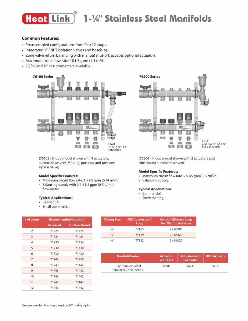
1-1⁄4" Stainless Steel Manifolds
Common Features:
• Preassembled confi gurations from 2 to 12 loops.
• Integrated 1" FNPT isolation valves and hosebibs.
• Zone valve return balancing with manual shut-off ; accepts optional actuators.
• Maximum trunk fl ow rate: 18 US gpm (4.1 m3/h)
• 1⁄2", 5⁄8", and 3⁄4" PEX connecters available.
(76105 - 5 loop model shown with 4 actuators,
automatic air vent, 1⁄2" plug, port cap, and pressure
bypass valve)
Model Specifi c Features:
• Maximum circuit fl ow rate: 1.5 US gpm (0.34 m3/h)
• Balancing supply with 0-1.5 US gpm (0-5 L/min)
fl ow meter.
Typical Applications:
• Residential.
• Small commercial.
(76204 - 4 loop model shown with 2 actuators and
side mount automatic air vent)
Model Specifi c Features:
• Maximum circuit fl ow rate: 2.5 US gpm (0.57m3/h)
• Balancing supply.
Typical Applications:
• Commercial.
• Snow melting.
76100 Series 76200 Series
®
Heat Link
76200 Series6100 Series
Tubing Size PEX Connecters /
Loop
Conduit Elbows / Loop
for “Wet” Installation
1⁄2" 77105 2× 86005
5⁄8" 77119 2× 86020
3⁄4" 77122 2× 86022
Manifold Series Actuator
with LED
Actuator with
End Switch
DDC Actuator
1-1⁄4" Stainless Steel
(76100 or 76200 series)
56201 56231 56121
# of Loops Recommended Housing*
Recessed Surface Mount
2 71724 71424
3 71724 71424
4 71730 71424
5 71730 71430
6 71730 71430
7 71743 71430
8 71743 71442
9 71743 71442
10 71743 71442
11 71743 71442
12 71743 71442
*recommended housing based on 90° mains piping
L to Rport cap, 1⁄2", 5⁄8", & 3⁄4" PEX connecters
L to R1⁄2", 5⁄8", & 3⁄4" PEX connecters
16
®
Heat Linkwww.heatlink.com
Ra
dia
nt H
eati
ng &
Coo
ling
1-1⁄4" Stainless Steel Manifolds
1-1⁄4" Stainless Steel Manifolds with Flow Meters
76100 Series
Manifold includes:
• 1 assembled fl ow balancing supply manifold with 1" FNPT isolation valve and
hose bib/air vent.
• 1 assembled balancing shut-off return manifold with 1" FNPT isolation valve
and hose bib/air vent.
• 2 mounting brackets.
PEX connecters & port caps sold separately.
1-1⁄4" High Flow Stainless Steel Manifolds
76200 Series
Manifold includes:
• 1 assembled balancing supply manifold with 1" FNPT isolation valve and hose
bib/air vent.
• 1 assembled balancing shut-off return manifold with 1" FNPT isolation valve
and hose bib/air vent.
• 2 mounting brackets.
PEX connecters & port caps sold separately.
USA - July 1, 2014
Stk# Description Pkg Qty Carton Qty Unit List Price / Unit
76102 2 Loop SS Manifold with Flow Meters 1 ea.
76103 3 Loop SS Manifold with Flow Meters 1 ea.
76104 4 Loop SS Manifold with Flow Meters 1 ea.
76105 5 Loop SS Manifold with Flow Meters 1 ea.
76106 6 Loop SS Manifold with Flow Meters 1 ea.
76107 7 Loop SS Manifold with Flow Meters 1 ea.
76108 8 Loop SS Manifold with Flow Meters 1 ea.
76109 9 Loop SS Manifold with Flow Meters 1 ea.
76110 10 Loop SS Manifold with Flow Meters 1 ea.
76111 11 Loop SS Manifold with Flow Meters 1 ea.
76112 12 Loop SS Manifold with Flow Meters 1 ea.
Stk# Description Pkg Qty Carton Qty Unit List Price / Unit
76202 2 Loop High Flow SS Manifold 1 ea.
76203 3 Loop High Flow SS Manifold 1 ea.
76204 4 Loop High Flow SS Manifold 1 ea.
76205 5 Loop High Flow SS Manifold 1 ea.
76206 6 Loop High Flow SS Manifold 1 ea.
76207 7 Loop High Flow SS Manifold 1 ea.
76208 8 Loop High Flow SS Manifold 1 ea.
76209 9 Loop High Flow SS Manifold 1 ea.
76210 10 Loop High Flow SS Manifold 1 ea.
76211 11 Loop High Flow SS Manifold 1 ea.
76212 12 Loop High Flow SS Manifold 1 ea.
17
®
Heat Linkwww.heatlink.com
Ra
dia
nt Hea
ting & Cooling
PEX Connecters for 1-1⁄4" Stainless Steel Manifolds
77100 Series
Solid brass fi tting attaches to the end of the PEX tubing and allows for easy
installation onto the bottom of the 1-1⁄4" SS manifold. Comes with o-ring.
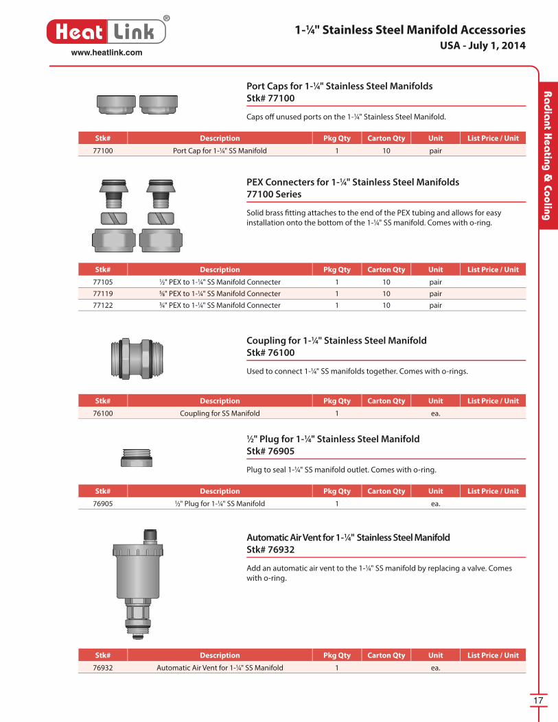
Port Caps for 1-1⁄4" Stainless Steel Manifolds
Stk# 77100
Caps off unused ports on the 1-1⁄4" Stainless Steel Manifold.
1-1⁄4" Stainless Steel Manifold Accessories
Coupling for 1-1⁄4" Stainless Steel Manifold
Stk# 76100
Used to connect 1-1⁄4" SS manifolds together. Comes with o-rings.
1⁄2" Plug for 1-1⁄4" Stainless Steel Manifold
Stk# 76905
Plug to seal 1-1⁄4" SS manifold outlet. Comes with o-ring.
Automatic Air Vent for 1-1⁄4" Stainless Steel Manifold
Stk# 76932
Add an automatic air vent to the 1-1⁄4" SS manifold by replacing a valve. Comes
with o-ring.
USA - July 1, 2014
Stk# Description Pkg Qty Carton Qty Unit List Price / Unit
77100 Port Cap for 1-1⁄4" SS Manifold 1 10 pair
Stk# Description Pkg Qty Carton Qty Unit List Price / Unit
77105 1⁄2" PEX to 1-1⁄4" SS Manifold Connecter 1 10 pair
77119 5⁄8" PEX to 1-1⁄4" SS Manifold Connecter 1 10 pair
77122 3⁄4" PEX to 1-1⁄4" SS Manifold Connecter 1 10 pair
Stk# Description Pkg Qty Carton Qty Unit List Price / Unit
76100 Coupling for SS Manifold 1 ea.
Stk# Description Pkg Qty Carton Qty Unit List Price / Unit
76905 1⁄2" Plug for 1-1⁄4" SS Manifold 1 ea.
Stk# Description Pkg Qty Carton Qty Unit List Price / Unit
76932 Automatic Air Vent for 1-1⁄4" SS Manifold 1 ea.
18
®
Heat Linkwww.heatlink.com
Ra
dia
nt H
eati
ng &
Coo
ling
1-1⁄4" Stainless Steel Manifold Accessories
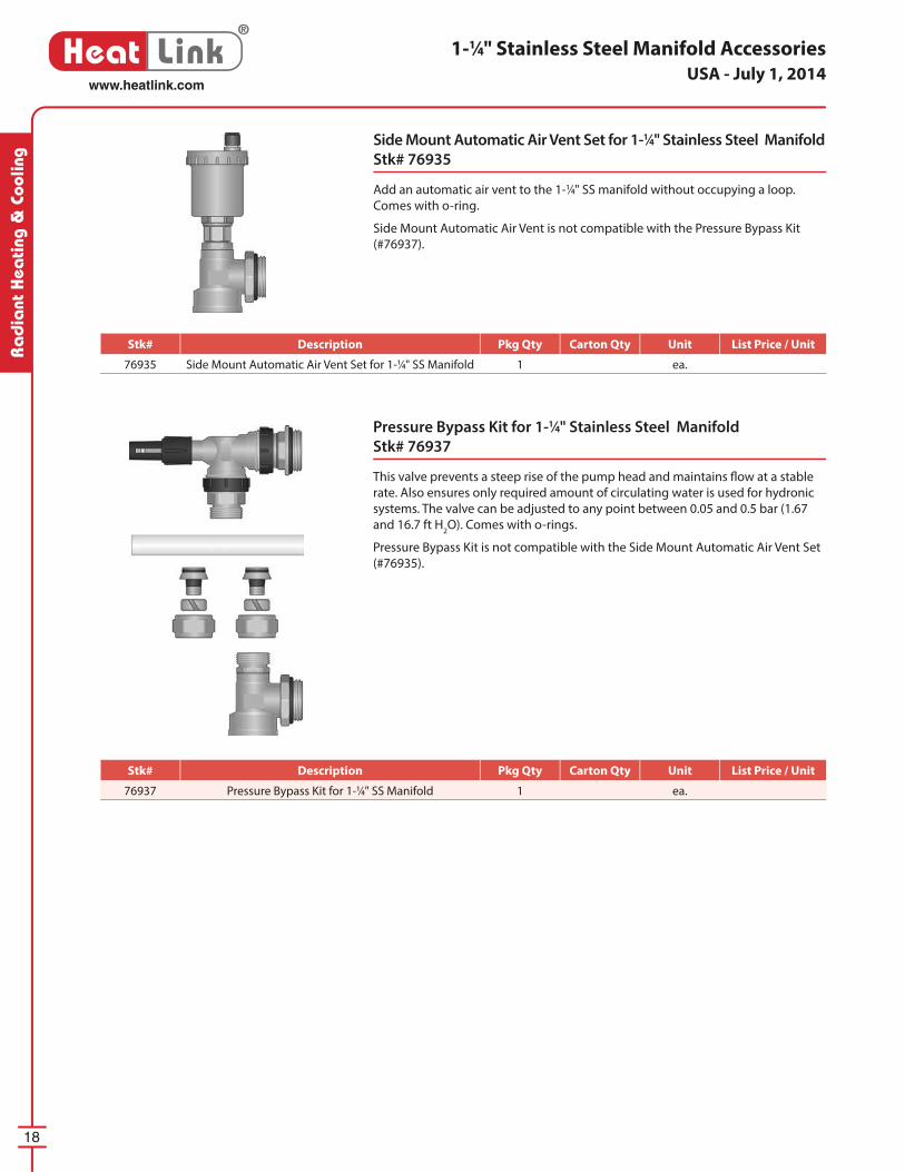
Pressure Bypass Kit for 1-1⁄4" Stainless Steel Manifold
Stk# 76937
This valve prevents a steep rise of the pump head and maintains fl ow at a stable
rate. Also ensures only required amount of cir cu lat ing water is used for hydronic
systems. The valve can be ad just ed to any point between 0.05 and 0.5 bar (1.67
and 16.7 ft H2O). Comes with o-rings.
Pressure Bypass Kit is not compatible with the Side Mount Automatic Air Vent Set
(#76935).
Side Mount Automatic Air Vent Set for 1-1⁄4" Stainless Steel Manifold
Stk# 76935
Add an automatic air vent to the 1-1⁄4" SS manifold without occupying a loop.
Comes with o-ring.
Side Mount Automatic Air Vent is not compatible with the Pressure Bypass Kit
(#76937).
USA - July 1, 2014
Stk# Description Pkg Qty Carton Qty Unit List Price / Unit
76935 Side Mount Automatic Air Vent Set for 1-1⁄4" SS Manifold 1 ea.
Stk# Description Pkg Qty Carton Qty Unit List Price / Unit
76937 Pressure Bypass Kit for 1-1⁄4" SS Manifold 1 ea.
19
®
Heat Linkwww.heatlink.com
Ra
dia
nt Hea
ting & Cooling
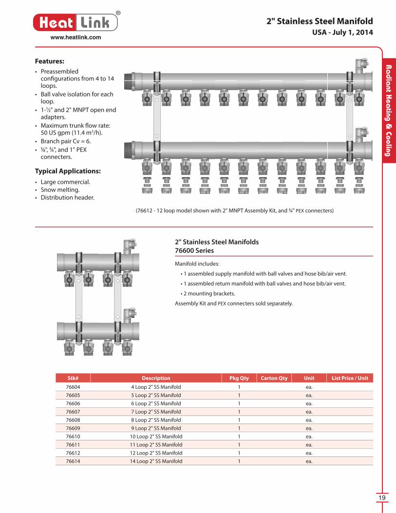
2" Stainless Steel Manifolds
76600 Series
Manifold includes:
• 1 assembled supply manifold with ball valves and hose bib/air vent.
• 1 assembled return manifold with ball valves and hose bib/air vent.
• 2 mounting brackets.
Assembly Kit and PEX connecters sold separately.
Features:
• Preassembled confi gurations from 4 to 14 loops.
• Ball valve isolation for each loop.
• 1-1⁄2" and 2" MNPT open end adapters.
• Maximum trunk fl ow rate: 50 US gpm (11.4 m3/h).
• Branch pair Cv = 6.
• 5⁄8", 3⁄4", and 1" PEX connecters.
Typical Applications:
• Large commercial.
• Snow melting.
• Distribution header.
(76612 - 12 loop model shown with 2" MNPT Assembly Kit, and 3⁄4" PEX connecters)
2" Stainless Steel ManifoldUSA - July 1, 2014
Stk# Description Pkg Qty Carton Qty Unit List Price / Unit
76604 4 Loop 2" SS Manifold 1 ea.
76605 5 Loop 2" SS Manifold 1 ea.
76606 6 Loop 2" SS Manifold 1 ea.
76607 7 Loop 2" SS Manifold 1 ea.
76608 8 Loop 2" SS Manifold 1 ea.
76609 9 Loop 2" SS Manifold 1 ea.
76610 10 Loop 2" SS Manifold 1 ea.
76611 11 Loop 2" SS Manifold 1 ea.
76612 12 Loop 2" SS Manifold 1 ea.
76614 14 Loop 2" SS Manifold 1 ea.
20
®
Heat Linkwww.heatlink.com
Ra
dia
nt H
eati
ng &
Coo
ling
2" Stainless Steel Manifold Accessories
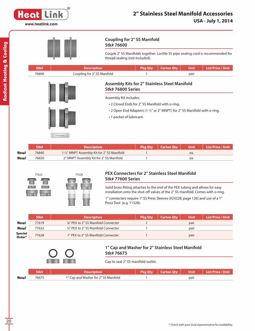
PEX Connecters for 2" Stainless Steel Manifold
Stk# 77600 Series
Solid brass fi tting attaches to the end of the PEX tubing and allows for easy
installation onto the shut-off valves of the 2" SS manifold. Comes with o-ring.
1" connecters require 1" SS Press Sleeves (#24228; page 126) and use of a 1"
Press Tool (e.g. 11328).
1" Cap and Washer for 2" Stainless Steel Manifold
Stk# 76675
Cap to seal 2" SS manifold outlet.
Assembly Kits for 2" Stainless Steel Manifold
Stk# 76800 Series
Assembly Kit includes:
• 2 Closed Ends for 2" SS Manifold with o-ring.
• 2 Open End Adapters (1-1⁄2" or 2" MNPT) for 2" SS Manifold with o-ring.
• 1 packet of lubricant.
Coupling for 2" SS Manifold
Stk# 76600
Couple 2" SS Manifolds together. Loctite 55 pipe sealing cord is recommended for
thread sealing (not included).
77622 77628
* Check with your local representative for availability.
USA - July 1, 2014
Stk# Description Pkg Qty Carton Qty Unit List Price / Unit
New! 76675 1" Cap and Washer for 2" SS Manifold 1 pair
Stk# Description Pkg Qty Carton Qty Unit List Price / Unit
New! 76840 1-1⁄2" MNPT Assembly Kit for 2" SS Manifold 1 ea.
New! 76850 2" MNPT Assembly Kit for 2" SS Manifold 1 ea.
Stk# Description Pkg Qty Carton Qty Unit List Price / Unit
New! 77619 5⁄8" PEX to 2" SS Manifold Connecter 1 pair
New! 77622 3⁄4" PEX to 2" SS Manifold Connecter 1 pair
Special Order* 77628 1" PEX to 2" SS Manifold Connecter 1 pair
Stk# Description Pkg Qty Carton Qty Unit List Price / Unit
76600 Coupling for 2" SS Manifold 1 pair
Manifold Manifold HousingsHousings
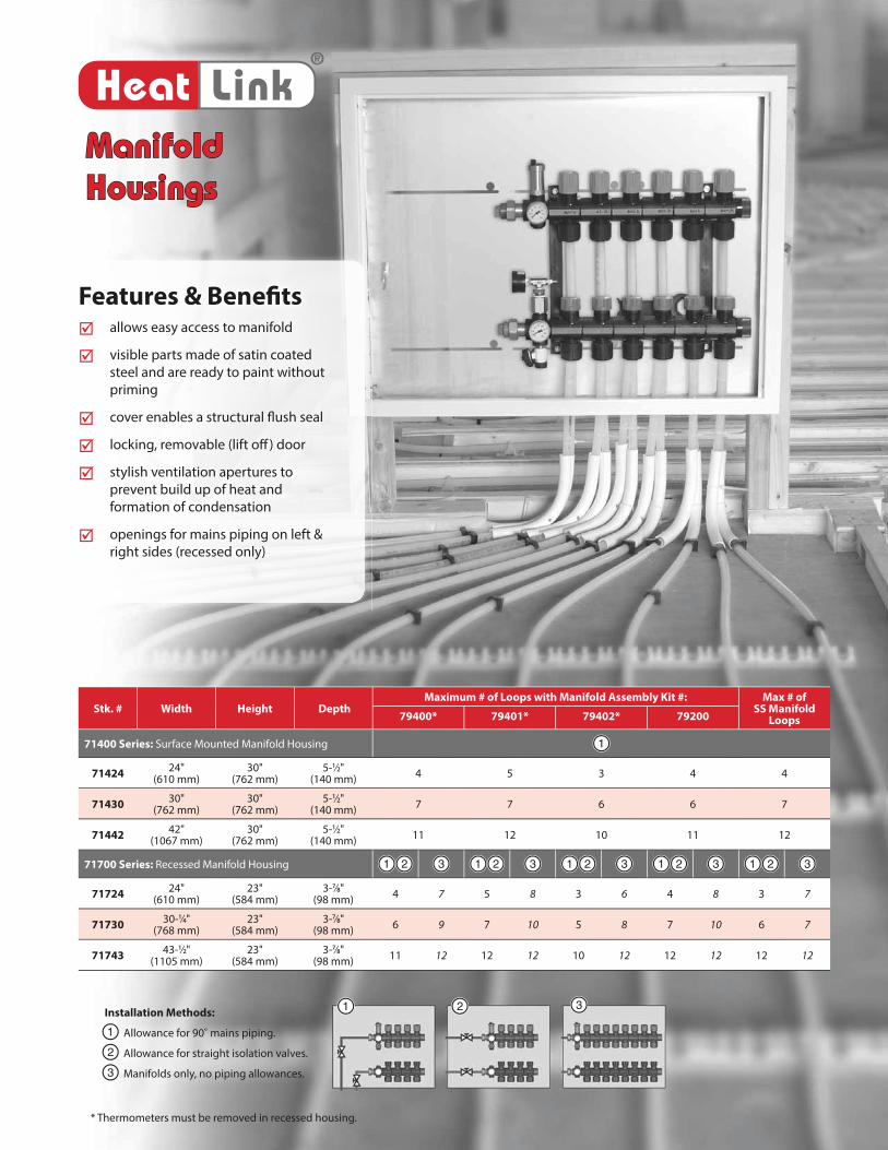
Stk. # Width Height DepthMaximum # of Loops with Manifold Assembly Kit #: Max # of
SS Manifold Loops79400* 79401* 79402* 79200
71400 Series: Surface Mounted Manifold Housing 1
7142424"
(610 mm)30"
(762 mm)5-1⁄2"
(140 mm)4 5 3 4 4
7143030"
(762 mm)30"
(762 mm)5-1⁄2"
(140 mm)7 7 6 6 7
7144242"
(1067 mm)30"
(762 mm)5-1⁄2"
(140 mm)11 12 10 11 12
71700 Series: Recessed Manifold Housing 1 2 3 1 2 3 1 2 3 1 2 3 1 2 3
7172424"
(610 mm)23"
(584 mm)3-7⁄8"
(98 mm)4 7 5 8 3 6 4 8 3 7
7173030-1⁄4"
(768 mm)23"
(584 mm)3-7⁄8"
(98 mm)6 9 7 10 5 8 7 10 6 7
7174343-1⁄2"
(1105 mm)23"
(584 mm)3-7⁄8"
(98 mm)11 12 12 12 10 12 12 12 12 12
®
Heat Link
* Thermometers must be removed in recessed housing.
Features & Benefi tsFeatures & Benefi ts allows easy access to manifold
visible parts made of satin coated
steel and are ready to paint without
priming
cover enables a structural fl ush seal
locking, removable (lift off ) door
stylish ventilation apertures to
prevent build up of heat and
formation of condensation
openings for mains piping on left &
right sides (recessed only)
321Installation Methods:
Allowance for 90˚ mains piping.
Allowance for straight isolation valves.
Manifolds only, no piping allowances.
1
2
3
22
®
Heat Linkwww.heatlink.com
Ra
dia
nt H
eati
ng &
Coo
ling
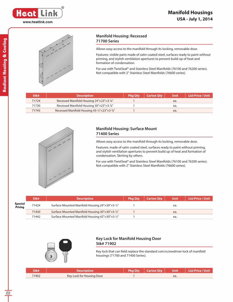
Manifold Housing: Surface Mount
71400 Series
Allows easy access to the manifold through its locking, removable door.
Features: made of satin coated steel, surfaces ready to paint without priming,
and stylish ventilation apertures to prevent build up of heat and formation of
condensation. Skirting by others.
For use with TwistSeal® and Stainless Steel Manifolds (76100 and 76200 series).
Not compatible with 2" Stainless Steel Manifolds (76600 series).
Manifold Housing: Recessed
71700 Series
Allows easy access to the manifold through its locking, removable door.
Features: visible parts made of satin coated steel, surfaces ready to paint without
priming, and stylish ventilation apertures to prevent build up of heat and
formation of condensation.
For use with TwistSeal® and Stainless Steel Manifolds (76100 and 76200 series).
Not compatible with 2" Stainless Steel Manifolds (76600 series).
Manifold Housings
Key Lock for Manifold Housing Door
Stk# 71902
Key lock that can fi eld replace the standard coin/screwdriver lock of manifold
housings (71700 and 71400 Series).
USA - July 1, 2014
Stk# Description Pkg Qty Carton Qty Unit List Price / Unit
71724 Recessed Manifold Housing 24"×23"×3-7⁄8" 1 ea.
71730 Recessed Manifold Housing 30"×23"×3-7⁄8" 1 ea.
71743 Recessed Manifold Housing 43-1⁄2"×23"×3-7⁄8" 1 ea.
Stk# Description Pkg Qty Carton Qty Unit List Price / Unit
Special Pricing 71424 Surface Mounted Manifold Housing 24"×30"×5-1⁄2" 1 ea.
71430 Surface Mounted Manifold Housing 30"×30"×5-1⁄2" 1 ea.
71442 Surface Mounted Manifold Housing 42"×30"×5-1⁄2" 1 ea.
Stk# Description Pkg Qty Carton Qty Unit List Price / Unit
71902 Key Lock for Housing Door 1 ea.
23
®
Heat Linkwww.heatlink.com
Ra
dia
nt Hea
ting & Cooling
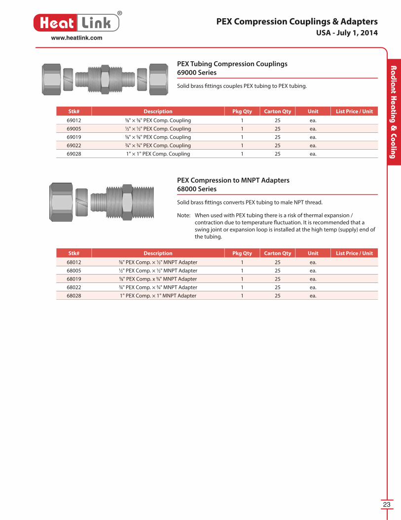
PEX Compression Couplings & Adapters
PEX Tubing Compression Couplings
69000 Series
Solid brass fi ttings couples PEX tubing to PEX tubing.
PEX Compression to MNPT Adapters
68000 Series
Solid brass fi ttings converts PEX tubing to male NPT thread.
Note: When used with PEX tubing there is a risk of thermal expansion /
contraction due to temperature fl uctuation. It is recommended that a
swing joint or expansion loop is installed at the high temp (supply) end of
the tubing.
USA - July 1, 2014
Stk# Description Pkg Qty Carton Qty Unit List Price / Unit
69012 3⁄8" × 3⁄8" PEX Comp. Coupling 1 25 ea.
69005 1⁄2" × 1⁄2" PEX Comp. Coupling 1 25 ea.
69019 5⁄8" × 5⁄8" PEX Comp. Coupling 1 25 ea.
69022 3⁄4" × 3⁄4" PEX Comp. Coupling 1 25 ea.
69028 1" × 1" PEX Comp. Coupling 1 25 ea.
Stk# Description Pkg Qty Carton Qty Unit List Price / Unit
68012 3⁄8" PEX Comp. × 1⁄2" MNPT Adapter 1 25 ea.
68005 1⁄2" PEX Comp. × 1⁄2" MNPT Adapter 1 25 ea.
68019 5⁄8" PEX Comp. x 3⁄4" MNPT Adapter 1 25 ea.
68022 3⁄4" PEX Comp. × 3⁄4" MNPT Adapter 1 25 ea.
68028 1" PEX Comp. × 1" MNPT Adapter 1 25 ea.
24
®
Heat Linkwww.heatlink.com
Ra
dia
nt H
eati
ng &
Coo
ling
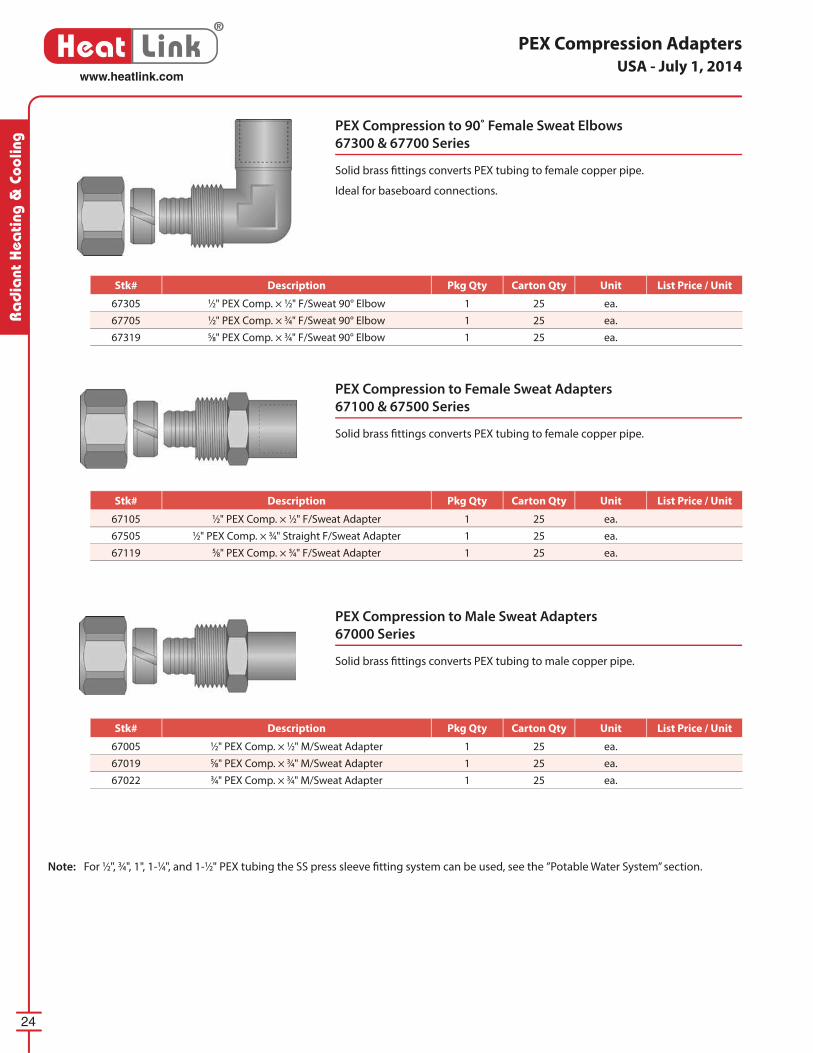
PEX Compression Adapters
PEX Compression to 90˚ Female Sweat Elbows
67300 & 67700 Series
Solid brass fi ttings converts PEX tubing to female copper pipe.
Ideal for baseboard connections.
PEX Compression to Female Sweat Adapters
67100 & 67500 Series
Solid brass fi ttings converts PEX tubing to female copper pipe.
PEX Compression to Male Sweat Adapters
67000 Series
Solid brass fi ttings converts PEX tubing to male copper pipe.
Note: For 1⁄2", 3⁄4", 1", 1-1⁄4", and 1-1⁄2" PEX tubing the SS press sleeve fi tting system can be used, see the ”Potable Water System” section.
USA - July 1, 2014
Stk# Description Pkg Qty Carton Qty Unit List Price / Unit
67305 1⁄2" PEX Comp. × 1⁄2" F/Sweat 90° Elbow 1 25 ea.
67705 1⁄2" PEX Comp. × 3⁄4" F/Sweat 90° Elbow 1 25 ea.
67319 5⁄8" PEX Comp. × 3⁄4" F/Sweat 90° Elbow 1 25 ea.
Stk# Description Pkg Qty Carton Qty Unit List Price / Unit
67105 1⁄2" PEX Comp. × 1⁄2" F/Sweat Adapter 1 25 ea.
67505 1⁄2" PEX Comp. × 3⁄4" Straight F/Sweat Adapter 1 25 ea.
67119 5⁄8" PEX Comp. × 3⁄4" F/Sweat Adapter 1 25 ea.
Stk# Description Pkg Qty Carton Qty Unit List Price / Unit
67005 1⁄2" PEX Comp. × 1⁄2" M/Sweat Adapter 1 25 ea.
67019 5⁄8" PEX Comp. × 3⁄4" M/Sweat Adapter 1 25 ea.
67022 3⁄4" PEX Comp. × 3⁄4" M/Sweat Adapter 1 25 ea.
25
®
Heat Linkwww.heatlink.com
Ra
dia
nt Hea
ting & Cooling
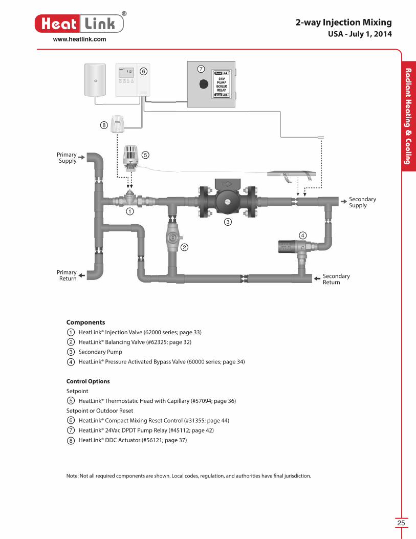
2-way Injection Mixing
Note: Not all required components are shown. Local codes, regulation, and authorities have fi nal jurisdiction.
Components
HeatLink® Injection Valve (62000 series; page 33)
HeatLink® Balancing Valve (#62325; page 32)
Secondary Pump
HeatLink® Pressure Activated Bypass Valve (60000 series; page 34)
Control Options
Setpoint
HeatLink® Thermostatic Head with Capillary (#57094; page 36)
Setpoint or Outdoor Reset
HeatLink® Compact Mixing Reset Control (#31355; page 44)
HeatLink® 24Vac DPDT Pump Relay (#45112; page 42)
HeatLink® DDC Actuator (#56121; page 37)
1
1
2
2
3
3
5
5
6
6
7
7
8
8
4
4
Primary Supply
Secondary Supply
Primary Return Secondary
Return
USA - July 1, 2014

26
®
Heat Linkwww.heatlink.com
Ra
dia
nt H
eati
ng &
Coo
ling
3-way Compact Mixing System
Note: Not all required components are shown. Local codes, regulation, and authorities have fi nal jurisdiction.
Components
HeatLink® Compact 3-way Mixing Valve (63700 series; page 31)
Secondary Pump
HeatLink® Pressure Activated Bypass Valve (60000 series; page 34)
Control Options
Setpoint
HeatLink® Thermostatic Head with Capillary (#57094; page 36)
Setpoint or Outdoor Reset
HeatLink® Compact Mixing Reset Control (#31355; page 44)
HeatLink® 24Vac DPDT Pump Relay (#45112; page 42)
HeatLink® DDC Actuator (#56121; page 37)
Panel Alternatives
TMP series - pages 72-79
TWH series - pages 80-85
CDP series - pages 92-95
SSTS series - pages 104-105
1
1
2
2
3
3
4
4
5
5
6
6
7
7
Primary Supply Secondary
Supply
Primary Return
Secondary Return
MECHANICALROOM IN A BOX
™
USA - July 1, 2014
27
®
Heat Linkwww.heatlink.com
Ra
dia
nt Hea
ting & Cooling
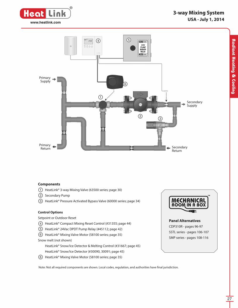
Components
HeatLink® 3-way Mixing Valve (63500 series; page 30)
Secondary Pump
HeatLink® Pressure Activated Bypass Valve (60000 series; page 34)
Control Options
Setpoint or Outdoor Reset
HeatLink® Compact Mixing Reset Control (#31355; page 44)
HeatLink® 24Vac DPDT Pump Relay (#45112; page 42)
HeatLink® Mixing Valve Motor (58100 series; page 35)
Snow melt (not shown)
HeatLink® Snow/Ice Detector & Melting Control (#31667; page 45)
HeatLink® Snow/Ice Detector (#30090, 30091; page 45)
HeatLink® Mixing Valve Motor (58100 series; page 35)
3-way Mixing System
Note: Not all required components are shown. Local codes, regulation, and authorities have fi nal jurisdiction.
1
1
2
2
3
3
4
4
5
5
6
6
6
Primary Supply
Secondary Supply
Primary Return Secondary
Return
Panel Alternatives
CDP310R - pages 96-97
SSTL series - pages 106-107
SMP series - pages 108-116
MECHANICALROOM IN A BOX
™
USA - July 1, 2014
28
®
Heat Linkwww.heatlink.com
Ra
dia
nt H
eati
ng &
Coo
ling
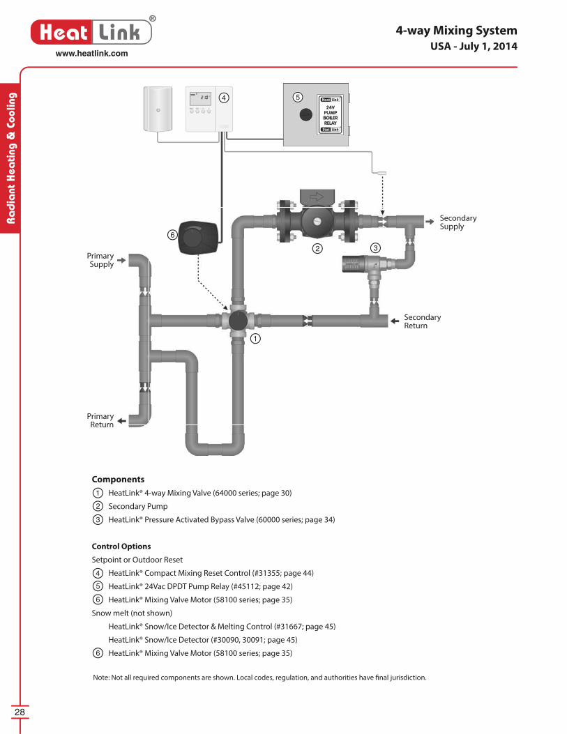
Components
HeatLink® 4-way Mixing Valve (64000 series; page 30)
Secondary Pump
HeatLink® Pressure Activated Bypass Valve (60000 series; page 34)
Control Options
Setpoint or Outdoor Reset
HeatLink® Compact Mixing Reset Control (#31355; page 44)
HeatLink® 24Vac DPDT Pump Relay (#45112; page 42)
HeatLink® Mixing Valve Motor (58100 series; page 35)
Snow melt (not shown)
HeatLink® Snow/Ice Detector & Melting Control (#31667; page 45)
HeatLink® Snow/Ice Detector (#30090, 30091; page 45)
HeatLink® Mixing Valve Motor (58100 series; page 35)
4-way Mixing System
Note: Not all required components are shown. Local codes, regulation, and authorities have fi nal jurisdiction.
1
1
2
2
3
3
4
4
5
5
6
6
6
Primary Supply
Secondary Supply
Primary Return
Secondary Return
USA - July 1, 2014
29
®
Heat Linkwww.heatlink.com
Ra
dia
nt Hea
ting & Cooling
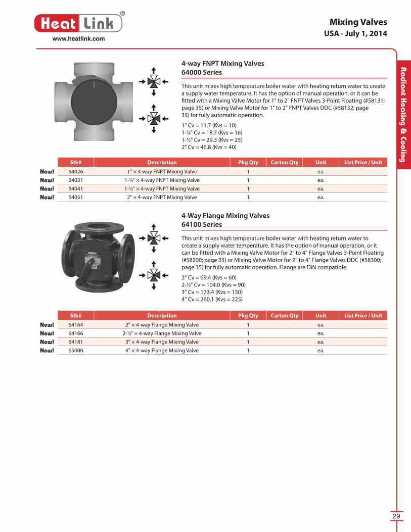
Mixing Valves
4-way FNPT Mixing Valves
64000 Series
This unit mixes high temperature boiler water with heating return water to create
a supply water temperature. It has the option of manual op er a tion, or it can be
fi tted with a Mixing Valve Motor for 1" to 2" FNPT Valves 3-Point Floating (#58131;
page 35) or Mixing Valve Motor for 1" to 2" FNPT Valves DDC (#58132; page
35) for fully automatic operation.
1" Cv = 11.7 (Kvs = 10)
1-1⁄4" Cv = 18.7 (Kvs = 16)
1-1⁄2" Cv = 29.3 (Kvs = 25)
2" Cv = 46.8 (Kvs = 40)
4-Way Flange Mixing Valves
64100 Series
This unit mixes high temperature boiler water with heating return water to
create a supply water temperature. It has the option of manual op er a tion, or it
can be fi tted with a Mixing Valve Motor for 2" to 4" Flange Valves 3-Point Floating
(#58200; page 35) or Mixing Valve Motor for 2" to 4" Flange Valves DDC (#58300;
page 35) for fully automatic operation. Flange are DIN compatible.
2" Cv = 69.4 (Kvs = 60)
2-1⁄2" Cv = 104.0 (Kvs = 90)
3" Cv = 173.4 (Kvs = 150)
4" Cv = 260.1 (Kvs = 225)
USA - July 1, 2014
Stk# Description Pkg Qty Carton Qty Unit List Price / Unit
New! 64164 2" × 4-way Flange Mixing Valve 1 ea.
New! 64166 2-1⁄2" × 4-way Flange Mixing Valve 1 ea.
New! 64181 3" × 4-way Flange Mixing Valve 1 ea.
New! 65000 4" × 4-way Flange Mixing Valve 1 ea.
Stk# Description Pkg Qty Carton Qty Unit List Price / Unit
New! 64026 1" × 4-way FNPT Mixing Valve 1 ea.
New! 64031 1-1⁄4" × 4-way FNPT Mixing Valve 1 ea.
New! 64041 1-1⁄2" × 4-way FNPT Mixing Valve 1 ea.
New! 64051 2" × 4-way FNPT Mixing Valve 1 ea.
30
®
Heat Linkwww.heatlink.com
Ra
dia
nt H
eati
ng &
Coo
ling
Mixing Valves
3-way FNPT Mixing / Diverting Valves
63500 Series
This unit mixes high temperature boiler water with heating return water to create
a supply water temperature. It has the option of manual op er a tion, or it can be
fi tted with a Mixing Valve Motor for 1" to 2" FNPT Valves 3-Point Floating (#58131;
page 35) or Mixing Valve Motor for 1" to 2" FNPT Valves DDC (#58132; page
35) for fully automatic operation.
1" Cv = 11.7 (Kvs = 10)
1-1⁄4" Cv = 18.7 (Kvs = 16)
1-1⁄2" Cv = 29.3 (Kvs = 25)
2" Cv = 46.8 (Kvs = 40)
4-way FNPT Mixing Valves
64000 Series
This unit mixes high temperature boiler water with heating return water to create
a supply water temperature. It has the option of manual op er a tion, or it can be
fi tted with a Mixing Valve Motor for 1" and 1-1⁄4" Valves (#58130; page 35) for
fully automatic operation.
1-1⁄4" Cv = 17.4 (Kvs = 15)
4-Way Flange Mixing Valves
64100 Series
This unit mixes high temperature boiler water with heating return water to
create a supply water temperature. It has the option of manual op er a tion, or it
can be fi tted with a mixing valve motor (#58199; page 35) for fully automatic
operation. Flanges are ANSI and DIN compatible.
2-1⁄2" Cv = 73.3 (Kvs = 63)
3" Cv = 116.3 (Kvs = 100)
USA - July 1, 2014
Stk# Description Pkg Qty Carton Qty Unit List Price / Unit
New! 63026 1" × 3-way FNPT Mixing / Diverting Valve 1 ea.
New! 63539 1-1⁄4" × 3-way FNPT Mixing / Diverting Valve 1 ea.
New! 63541 1-1⁄2" × 3-way FNPT Mixing / Diverting Valve 1 ea.
New! 63551 2" × 3-way FNPT Mixing / Diverting Valve 1 ea.
Stk# Description Pkg Qty Carton Qty Unit List Price / Unit
WSL 64030 1-1⁄4" × 4-way FNPT Mixing Valve 1 ea.
Stk# Description Pkg Qty Carton Qty Unit List Price / Unit
WSL 64165 2-1⁄2" × 4-way Flange Mixing Valve 1 ea.
WSL 64180 3" × 4-way Flange Mixing Valve 1 ea.
31
®
Heat Linkwww.heatlink.com
Ra
dia
nt Hea
ting & Cooling
Mixing Valves
Compact 3-Way Mixing Valves
63700 Series
Three-way mixing valve for fl uid temperature control in heating and cooling
systems. Bronze valve body with brass nipples, protective cap, and stainless
spindle with double O-ring seal. Threads are compatible with actuators (#56201,
#56231, #56121; page 37) and thermostatic heads (#57091 and #57094; page
36).
1⁄2" Cv = 2.9 (Kv = 2.5)3⁄4" Cv = 4.1 (Kv = 3.5)
1" Cv = 5.3 (Kv = 4.6)
1-1⁄4" Cv = 7.4 (Kv = 6.4)
1" 3-Way Diverter Valve
Stk# 63025
Provides on/off or modulated fl ow control with bypass for man i folds or
mis cel la ne ous sup ple men tal heating units. Fitted with three 1" sweat unions.
Threads are compatible with actuators (#56201, #56231, #56121; page 37) and
thermostatic heads (#57091 and #57094; page 36).
Cv = 6.0 (Kv = 5.12)
USA - July 1, 2014
Stk# Description Pkg Qty Carton Qty Unit List Price / Unit
WSL 63025 1" × 3-way Mixing/Diverting Valve 1 ea.
Stk# Description Pkg Qty Carton Qty Unit List Price / Unit
63716 1⁄2" Compact 3-way Mixing Valve 1 ea.
63720 3⁄4" Compact 3-way Mixing Valve 1 ea.
63725 1" Compact 3-way Mixing Valve 1 ea.
63732 1-1⁄4" Compact 3-way Mixing Valve 1 ea.
32
®
Heat Linkwww.heatlink.com
Ra
dia
nt H
eati
ng &
Coo
ling
Valves
Straight Radiator Valves
62200 Series
Provides on/off or modulated fl ow control for miscellaneous sup ple men tal
heating units (e.g. towel warmers). Nickel plated. Threads are compatible with
actuators (#56201, #56231, #56121; page 37) and thermostatic heads (#57091
and #57094; page 36).
1⁄2" Cv = 1.6 (Kv = 1.35)3⁄4" Cv = 2.9 (Kv = 2.5)
90˚ Angle Radiator Valves
62100 Series
Provides on/off or modulated fl ow control for miscellaneous supplemental
heating units (e.g. towel warmers). Nickel plated. Threads are compatible with
actuators (#56201, #56231, #56121; page 37) and thermostatic heads (#57091
and #57094; page 36).
1⁄2" Cv = 1.6 (Kv = 1.35)3⁄4" Cv = 2.9 (Kv = 2.5)
USA - July 1, 2014
Straight Balancing Valve 1" Female Sweat
Stk# 62325
Flow balancing valve for use in injection systems and with the side stream fi lter.
Stk# Description Pkg Qty Carton Qty Unit List Price / Unit
62325 Straight Balancing Valve 1" F/Sweat 1 24 ea.
Stk# Description Pkg Qty Carton Qty Unit List Price / Unit
62116 90° Angle Radiator Valve 1⁄2", Nickel Plated 1 5 ea.
62120 90° Angle Radiator Valve 3⁄4", Nickel Plated 1 20 ea.
Stk# Description Pkg Qty Carton Qty Unit List Price / Unit
62216 Straight Radiator Valve 1⁄2", Nickel Plated 1 20 ea.
62220 Straight Radiator Valve 3⁄4", Nickel Plated 1 20 ea.
33
®
Heat Linkwww.heatlink.com
Ra
dia
nt Hea
ting & Cooling
Valves
1⁄2" Straight Return Connecter
Stk# 61016
Provides balancing for miscellaneous sup ple men tal heating units (e.g. towel
warmers). Gives a clean exposed fi nish when used with the HeatLink® zone valves
in supplemental heat applications. Nickel plated.
Cv = 1.6 (Kv = 1.35)
1⁄2" 90˚ Angle Return Connecter
Stk# 61116
Provides balancing for miscellaneous sup ple men tal heating units (e.g. towel
warmers). Gives a clean exposed fi nish when used with the HeatLink® zone valves
in supplemental heat applications. Nickel plated.
Cv = 1.6 (Kv = 1.35)
Straight Zone Valves/Injection Valves
62000 Series
Provides on/off or modulated fl ow control for baseboard, fan coils, manifolds,
and injection controls. Threads are compatible with actuators (#56201, #56231,
#56121; page 37) and thermostatic heads (#57091 and #57094; page 36).
1⁄2" Cv = 2.9 (Kv = 2.5)3⁄4" Cv = 4.2 (Kv = 3.6)
1" Cv = 4.9 (Kv = 4.2)
1-1⁄4" Cv = 6.8 (Kv = 5.8)
USA - July 1, 2014
Stk# Description Pkg Qty Carton Qty Unit List Price / Unit
62016 Straight Zone Valve 1⁄2" NPT 1 5 ea.
62020 Straight Zone Valve 3⁄4" NPT 1 5 ea.
62025 Straight Zone Valve 1" NPT 1 ea.
62030 Straight Zone Valve 1-1⁄4" NPT 1 ea.
Stk# Description Pkg Qty Carton Qty Unit List Price / Unit
61016 Straight Return Connecter 1⁄2" 1 20 ea.
Stk# Description Pkg Qty Carton Qty Unit List Price / Unit
61116 90° Angle Return Connecter 1⁄2" 1 5 ea.
34
®
Heat Linkwww.heatlink.com
Ra
dia
nt H
eati
ng &
Coo
ling
Valves
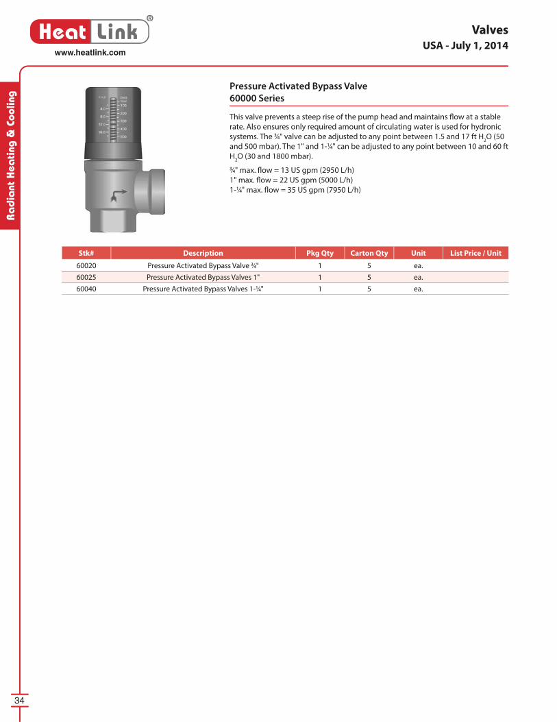
Pressure Activated Bypass Valve
60000 Series
This valve prevents a steep rise of the pump head and maintains fl ow at a stable
rate. Also ensures only required amount of cir cu lat ing water is used for hydronic
systems. The 3⁄4" valve can be ad just ed to any point between 1.5 and 17 ft H2O (50
and 500 mbar). The 1" and 1-1⁄4" can be adjusted to any point between 10 and 60 ft
H2O (30 and 1800 mbar).
3⁄4" max. fl ow = 13 US gpm (2950 L/h)
1" max. fl ow = 22 US gpm (5000 L/h)
1-1⁄4" max. fl ow = 35 US gpm (7950 L/h)
USA - July 1, 2014
Stk# Description Pkg Qty Carton Qty Unit List Price / Unit
60020 Pressure Activated Bypass Valve 3⁄4" 1 5 ea.
60025 Pressure Activated Bypass Valves 1" 1 5 ea.
60040 Pressure Activated Bypass Valves 1-1⁄4" 1 5 ea.
35
®
Heat Linkwww.heatlink.com
Ra
dia
nt Hea
ting & Cooling
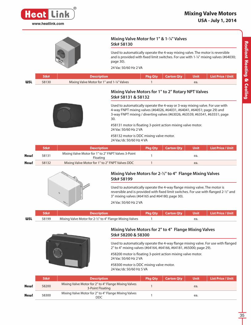
Mixing Valve Motors
Mixing Valve Motors for 2" to 4" Flange Mixing Valves
Stk# 58200 & 58300
Used to automatically operate the 4-way fl ange mixing valve. For use with fl anged
2" to 4" mixing valves (#64164, #64166, #64181, #65000; page 29).
#58200 motor is fl oating 3-point action mixing valve motor.
24 Vac 50/60 Hz 2 VA
#58300 motor is DDC mixing valve motor.
24 Vac/dc 50/60 Hz 5 VA
Mixing Valve Motors for 2-1⁄2" to 4" Flange Mixing Valves
Stk# 58199
Used to automatically operate the 4-way fl ange mixing valve. The motor is
re vers ible and is provided with fi xed limit switches. For use with fl anged 2-1⁄2" and
3" mixing valves (#64165 and #64180; page 30).
24 Vac 50/60 Hz 2 VA
Mixing Valve Motors for 1" to 2" Rotary NPT Valves
Stk# 58131 & 58132
Used to automatically operate the 4-way or 3-way mixing valve. For use with
4-way FNPT mixing valves (#64026, #64031, #64041, #64051; page 29) and
3-way FNPT mixing / diverting valves (#63026, #63539, #63541, #63551; page
30.
#58131 motor is fl oating 3-point action mixing valve motor.
24 Vac 50/60 Hz 2 VA
#58132 motor is DDC mixing valve motor.
24 Vac/dc 50/60 Hz 4 VA
Mixing Valve Motor for 1" & 1-1⁄4" Valves
Stk# 58130
Used to automatically operate the 4-way mixing valve. The motor is reversible
and is provided with fi xed limit switches. For use with 1-1⁄4" mixing valves (#64030;
page 30).
24 Vac 50/60 Hz 2 VA
USA - July 1, 2014
Stk# Description Pkg Qty Carton Qty Unit List Price / Unit
New! 58131Mixing Valve Motor for 1" to 2" FNPT Valves 3-Point
Floating1 ea.
New! 58132 Mixing Valve Motor for 1" to 2" FNPT Valves DDC 1 ea.
Stk# Description Pkg Qty Carton Qty Unit List Price / Unit
WSL 58199 Mixing Valve Motor for 2-1⁄2" to 4" Flange Mixing Valves 1 ea.
Stk# Description Pkg Qty Carton Qty Unit List Price / Unit
WSL 58130 Mixing Valve Motor for 1" and 1-1⁄4" Valves 1 ea.
Stk# Description Pkg Qty Carton Qty Unit List Price / Unit
New! 58200Mixing Valve Motor for 2" to 4" Flange Mixing Valves
3-Point Floating1 ea.
New! 58300Mixing Valve Motor for 2" to 4" Flange Mixing Valves
DDC1 ea.
36
®
Heat Linkwww.heatlink.com
Ra
dia
nt H
eati
ng &
Coo
ling
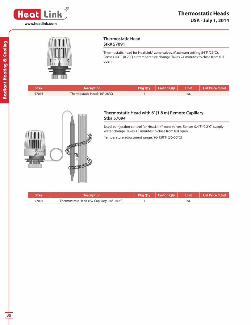
Thermostatic Head
Stk# 57091
Thermostatic head for HeatLink® zone valves. Maximum setting 84˚F (29˚C).
Senses 0.4˚F (0.2˚C) air temperature change. Takes 24 minutes to close from full
open.
Thermostatic Head with 6' (1.8 m) Remote Cap il lary
Stk# 57094
Used as injection control for HeatLink® zone valves. Senses 0.4˚F (0.2˚C) supply
water change. Takes 15 minutes to close from full open.
Temperature adjustment range: 96-150°F (36-66°C)
Thermostatic HeadsUSA - July 1, 2014
Stk# Description Pkg Qty Carton Qty Unit List Price / Unit
57091 Thermostatic Head (16°-28°C) 1 ea.
Stk# Description Pkg Qty Carton Qty Unit List Price / Unit
57094 Thermostatic Head c/w Capillary (86°-149°F) 1 ea.
37
®
Heat Linkwww.heatlink.com
Ra
dia
nt Hea
ting & Cooling
Actuators
Actuators
56200 Series
These actuators allow for additional room temperature control in con junc tion
with a room thermostat by mounting on a TwistSeal® supply man i fold module
(56200), Stainless Steel Manifold (56201), HeatLink® 62000 & 63000 series zone
valves (56201), or TwistSeal® Multiport Manifold (56202). Includes a heat demand
LED indicator.
Actuators c/w End Switch
56230 Series
These motors allow for additional room temperature control in con junc tion with
a room thermostat by mounting on a TwistSeal® supply man i fold module (56230),
Stainless Steel Manifold (56231), HeatLink® 62000 & 63000 series zone valves
(56231), or TwistSeal® Multiport Manifold (56232). Comes complete with end
switch to allow pump and/or boiler switching.
DDC Actuator
Stk# 56121
These actuators allow for additional room temperature control when used in
conjunction with a direct digital control system by mounting on a Stainless Steel
Manifold, or HeatLink® 62000 & 63000 series zone valves.
5620256200/1
5623256230/1
How to tell the 562x0 and 562x1 actuators apart
Actuator LED End Switch Female Thread Center Pin Mounts on
56200 Yes No Fine Yes TwistSeal® 78200 & 78400
56201 Yes No Coarse No Valves & SS manifolds
56230 No Yes Fine Yes TwistSeal® 78200 & 78400
56231 No Yes Coarse No Valves & SS manifolds
56201 / 5623156200 / 56230
USA - July 1, 2014
Stk# Description Pkg Qty Carton Qty Unit List Price / Unit
56230 HeatLink® TwistSeal® Manifold Actuator c/w End Switch 1 100 ea.
56231 HeatLink® Valve & SS Manifold Actuator c/w End Switch 1 100 ea.
56232 HeatLink® Multiport Manifold Actuator c/w End Switch 1 100 ea.
Stk# Description Pkg Qty Carton Qty Unit List Price / Unit
56200 HeatLink® TwistSeal® Manifold Actuator with LED 1 100 ea.
56201 HeatLink® Valve & SS Manifold Actuator with LED 1 100 ea.
56202 HeatLink® Multiport Manifold Actuator with LED 1 100 ea.
Stk# Description Pkg Qty Carton Qty Unit List Price / Unit
56121 HeatLink® DDC Actuator for Manifolds and Valves 1 100 ea.
Digital Thermostat
#46544• proportional integral
temperature regulation
• fully menu driven
• large digital display
• manual or automatic (external
timer) setback
• adjustable setback temperature
• room, fl oor or combined sensor
operation
• adjustable characteristics for
system optimization (high mass,
low mass, baseboard, fan coil and
cooling)
HeatLink did some simple addition, and
came up with a signifi cant innovation.
By adding an LED on our new StatLink®
zone drive actuator, HeatLink has reduced
the waiting time. The LED immediately
indicates heat demand. Along with our
new thermostats and zone modules, the
result is a completely visual feedback
system. To sum it up, it’s situation
normal…at-a-glance.
We’ve also gone color-coded and
digital. Of the fi ve thermostats StatLink®
now off ers, one is mechanical, one is
electronic, and three are digital. The
manual or automatic setback on the
electronic and digital thermostats,
provide energy savings by lowering the
temperature of unoccupied rooms.
All thermostats are designed for use
with standard AWG 18 cable. Our screw
terminals are color-coded to match the
wire colors found in fi re-alarm cable
(FAS105).
Our StatLink® modules simplify the
whole wiring process, and eliminate that
tangled mess of wires. The color-coded
screw terminals indicate where each wire
goes in the heating zones. Each zone
has an LED indicator for heat demand,
and up to 4 actuators can be connected
to each zone. It also acts as a combined
end-switch for all zones, by activating the
boiler and pump when heat is required.
HeatLink’s new StatLink® system saves
the contractor both time and money, by
focusing on ease of installation and ease
of use. The new StatLink® is a welcome
addition to the HeatLink family, and our
customers will fi nd it is an excellent fi t
with our other product lines.
Electronic Control System
Electronic Thermostat
#46443• analog electronic
regulation
• heat demand LED
• large, easy to adjust dial
• 3 position operation
selector switch: heat,
manual or automatic
(external timer) setback
• setback of 4˚C (7˚F)
• 3 or 4 wire operation
• internal or external sensor
operation
®
LinkStat
24Vac Power
external
sensor
Dual Dry Contacts

Digital Timer Thermostat
#46643• proportional integral temperature
regulation
• fully menu driven
• large digital display
• easy to program 7 day 24 hour timer with 4
user programs and 9 fi xed programs
• room, fl oor or combined sensor operation
• setback signal feedback to StatLink®
• ITCS function for intelligent setback
functionality
• adjustable characteristics for system
optimization (high mass, low mass,
baseboard, fan coil and cooling)
Digital Heat/Cool Timer Thermostat
#46673• proportional integral temperature regulation
• fully menu driven
• large digital display
• easy to program 7 day 24 hour timer with 4
user programs and 9 fi xed programs
• room, fl oor or combined sensor operation
• setback signal feedback to StatLink®
• ITCS function for intelligent setback
functionality
• adjustable characteristics for system
optimization (high mass, low mass,
baseboard, fan coil and cooling)
• heat, cool, fan, or automatic operation
Actuators
#56200 Series• heat demand LED indicator
• available with endswitch
StatLink® 6 Zone Base Module - #40226• 24Vac input
• boiler and pump switching via dual dry contacts
• heat demand LEDs for each zone
• up to 4 actuators per zone
• max. 12 actuators with the addition of a 60VA
transformer
StatLink® 4 Zone Expansion Module - #40234
(not shown)
• easy addition of 4 zones
• heat demand LEDs for each zone
• up to 4 actuators per zone
StatLink® 2 Zone Heavy Duty Expansion
Module - #40242• easy addition of 2 zones
• heat demand LEDs for each zone
• up to 12 actuators per zone
cooling
contacts
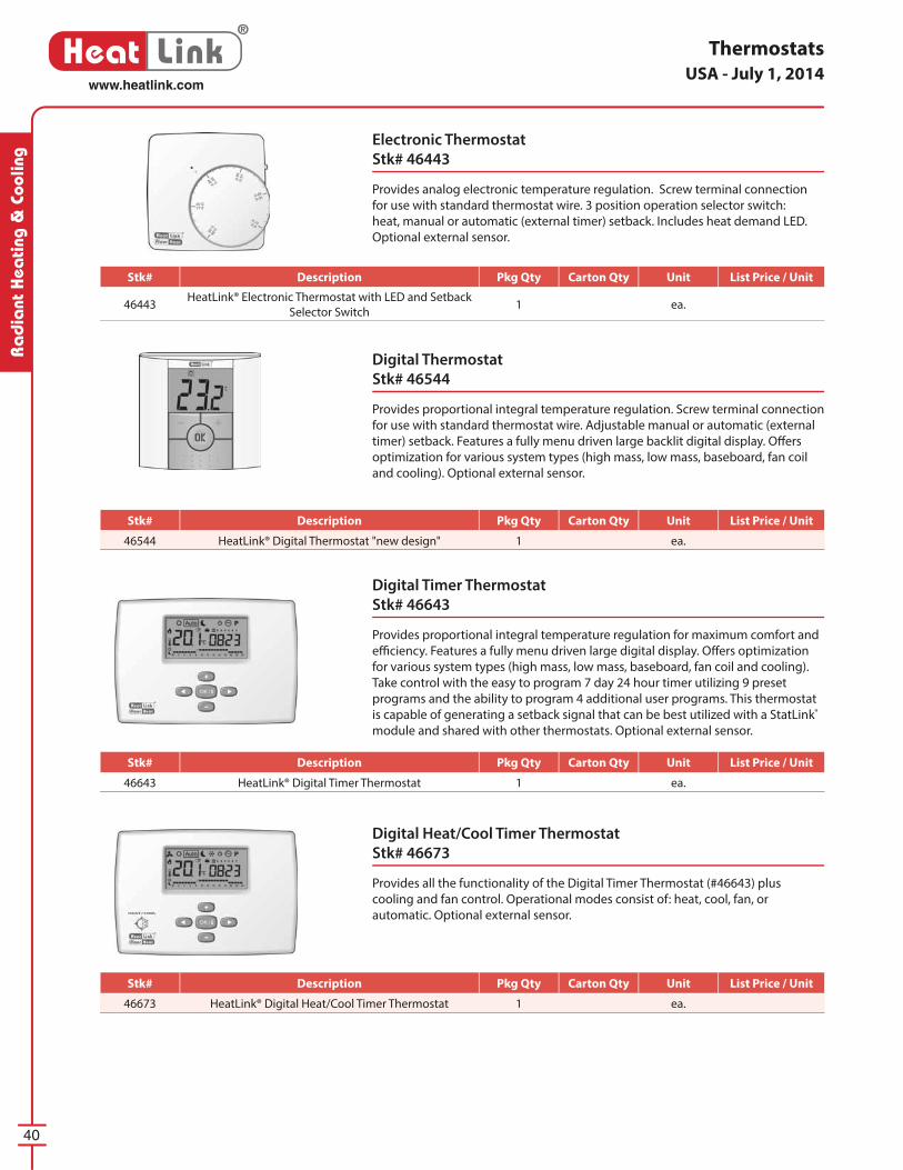
40
®
Heat Linkwww.heatlink.com
Ra
dia
nt H
eati
ng &
Coo
ling
Digital Thermostat
Stk# 46544
Provides proportional integral temperature regulation. Screw terminal connection
for use with standard thermostat wire. Adjustable manual or automatic (external
timer) setback. Features a fully menu driven large backlit digital display. Off ers
optimization for various system types (high mass, low mass, baseboard, fan coil
and cooling). Optional external sensor.
Electronic Thermostat
Stk# 46443
Provides analog electronic temperature regulation. Screw terminal connection
for use with standard thermostat wire. 3 position operation selector switch:
heat, manual or automatic (external timer) setback. Includes heat demand LED.
Optional external sensor.
Digital Timer Thermostat
Stk# 46643
Provides proportional integral temperature regulation for maximum comfort and
effi ciency. Features a fully menu driven large digital display. Off ers optimization
for various system types (high mass, low mass, baseboard, fan coil and cooling).
Take control with the easy to program 7 day 24 hour timer utilizing 9 preset
programs and the ability to program 4 additional user programs. This thermostat
is capable of generating a setback signal that can be best utilized with a StatLink®
module and shared with other thermostats. Optional external sensor.
Digital Heat/Cool Timer Thermostat
Stk# 46673
Provides all the functionality of the Digital Timer Thermostat (#46643) plus
cooling and fan control. Operational modes consist of: heat, cool, fan, or
automatic. Optional external sensor.
ThermostatsUSA - July 1, 2014
Stk# Description Pkg Qty Carton Qty Unit List Price / Unit
46443HeatLink® Electronic Thermostat with LED and Setback
Selector Switch1 ea.
Stk# Description Pkg Qty Carton Qty Unit List Price / Unit
46544 HeatLink® Digital Thermostat "new design" 1 ea.
Stk# Description Pkg Qty Carton Qty Unit List Price / Unit
46643 HeatLink® Digital Timer Thermostat 1 ea.
Stk# Description Pkg Qty Carton Qty Unit List Price / Unit
46673 HeatLink® Digital Heat/Cool Timer Thermostat 1 ea.

You’re in Control
A traditional forced air system with one
central thermostat may need to be set
higher than necessary to ensure that some
parts of the house get suffi cient heat.
With HeatLink ® radiant fl oor heating,
a house can be divided into diff erent
heating zones. Each zone will have it’s own
thermostat that will set it’s temperature
independently from the other zones. This
means that you can heat only the rooms
that need heat. Rooms that don’t need
to be heated can be put into “setback,” a
lower user adjustable temperature, to save
energy.
Add a timer thermostat to automatically
switch between normal operation and
setback operation on a set schedule. This
schedule will let you automatically lower
the temperature of your home when no
one’s home and bring the temperature
back up to greet you upon your return.
… because every
family has
diff erent needs,
and every home
is unique.
Example:
Living area is heated in the morning and evening, and setback during the day and at night.
Bedrooms are heated during the night, and setback during the day.
Less frequently used rooms can be manually switched to and from setback mode.
®
LinkStat
Living Room
Master Bedroom
Bedroom #2
Garage
KitchenDen
Dining Room
Normal operationSetback operation
Normal operationSetback operation
24 hour schedule
Setback Channel 1 - Living Area
Setback Channel 2 - Bedrooms
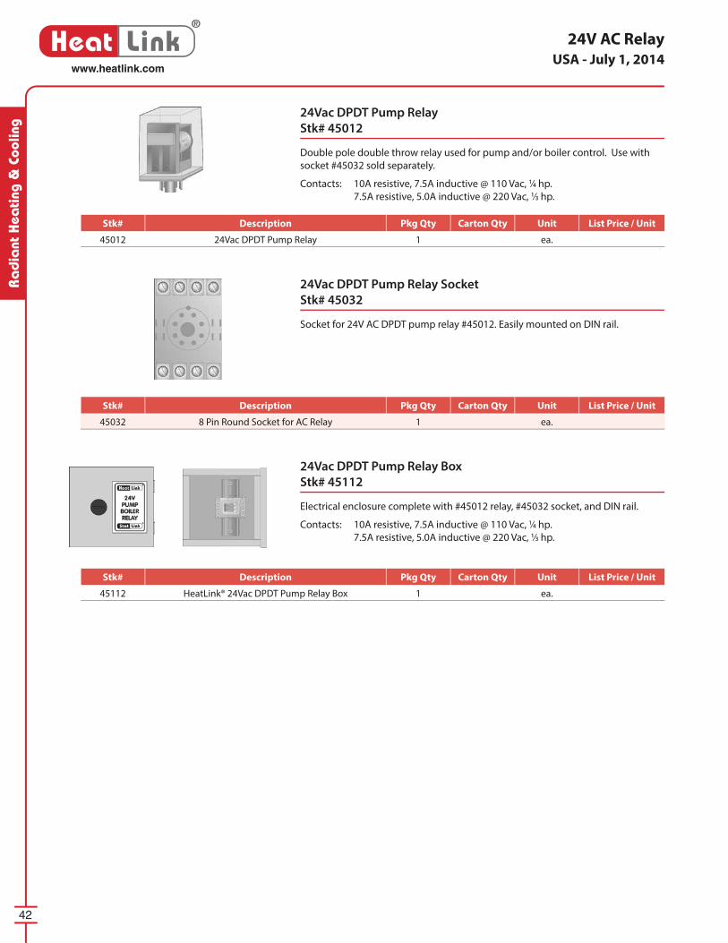
42
®
Heat Linkwww.heatlink.com
Ra
dia
nt H
eati
ng &
Coo
ling
24V AC Relay
24Vac DPDT Pump Relay
Stk# 45012
Double pole double throw relay used for pump and/or boiler control. Use with
socket #45032 sold separately.
Contacts: 10A resistive, 7.5A inductive @ 110 Vac, 1⁄4 hp.
7.5A resistive, 5.0A inductive @ 220 Vac, 1⁄3 hp.
24Vac DPDT Pump Relay Box
Stk# 45112
Electrical enclosure complete with #45012 relay, #45032 socket, and DIN rail.
Contacts: 10A resistive, 7.5A inductive @ 110 Vac, 1⁄4 hp.
7.5A resistive, 5.0A inductive @ 220 Vac, 1⁄3 hp.
24Vac DPDT Pump Relay Socket
Stk# 45032
Socket for 24V AC DPDT pump relay #45012. Easily mounted on DIN rail.
USA - July 1, 2014
Stk# Description Pkg Qty Carton Qty Unit List Price / Unit
45012 24Vac DPDT Pump Relay 1 ea.
Stk# Description Pkg Qty Carton Qty Unit List Price / Unit
45032 8 Pin Round Socket for AC Relay 1 ea.
Stk# Description Pkg Qty Carton Qty Unit List Price / Unit
45112 HeatLink® 24Vac DPDT Pump Relay Box 1 ea.
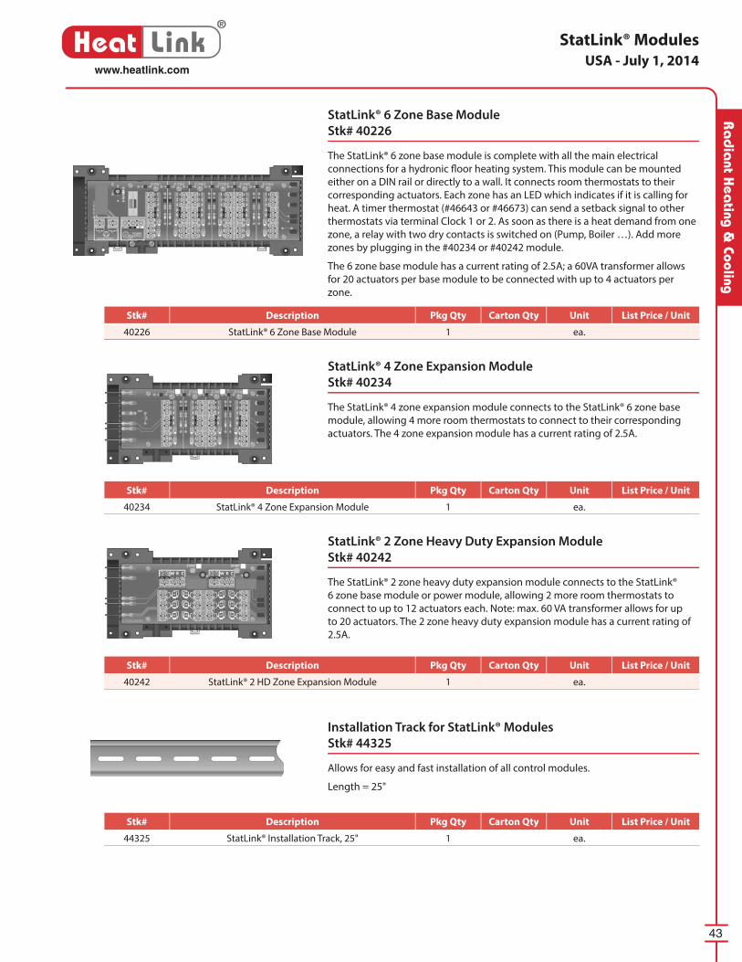
43
®
Heat Linkwww.heatlink.com
Ra
dia
nt Hea
ting & Cooling
StatLink® 4 Zone Expansion Module
Stk# 40234
The StatLink® 4 zone expansion module connects to the StatLink® 6 zone base
module, allowing 4 more room thermostats to connect to their corresponding
actuators. The 4 zone expansion module has a current rating of 2.5A.
StatLink® Modules
StatLink® 6 Zone Base Module
Stk# 40226
The StatLink® 6 zone base module is complete with all the main electrical
connections for a hydronic fl oor heating system. This module can be mounted
either on a DIN rail or directly to a wall. It connects room thermostats to their
corresponding actuators. Each zone has an LED which indicates if it is calling for
heat. A timer thermostat (#46643 or #46673) can send a setback signal to other
thermostats via terminal Clock 1 or 2. As soon as there is a heat demand from one
zone, a relay with two dry contacts is switched on (Pump, Boiler …). Add more
zones by plugging in the #40234 or #40242 module.
The 6 zone base module has a current rating of 2.5A; a 60VA transformer allows
for 20 actuators per base module to be connected with up to 4 actuators per
zone.
StatLink® 2 Zone Heavy Duty Expansion Module
Stk# 40242
The StatLink® 2 zone heavy duty expansion module connects to the StatLink®
6 zone base module or power module, allowing 2 more room thermostats to
connect to up to 12 actuators each. Note: max. 60 VA transformer allows for up
to 20 actuators. The 2 zone heavy duty expansion module has a current rating of
2.5A.
Installation Track for StatLink® Modules
Stk# 44325
Allows for easy and fast installation of all control modules.
Length = 25"
USA - July 1, 2014
Stk# Description Pkg Qty Carton Qty Unit List Price / Unit
40226 StatLink® 6 Zone Base Module 1 ea.
Stk# Description Pkg Qty Carton Qty Unit List Price / Unit
40234 StatLink® 4 Zone Expansion Module 1 ea.
Stk# Description Pkg Qty Carton Qty Unit List Price / Unit
40242 StatLink® 2 HD Zone Expansion Module 1 ea.
Stk# Description Pkg Qty Carton Qty Unit List Price / Unit
44325 StatLink® Installation Track, 25" 1 ea.
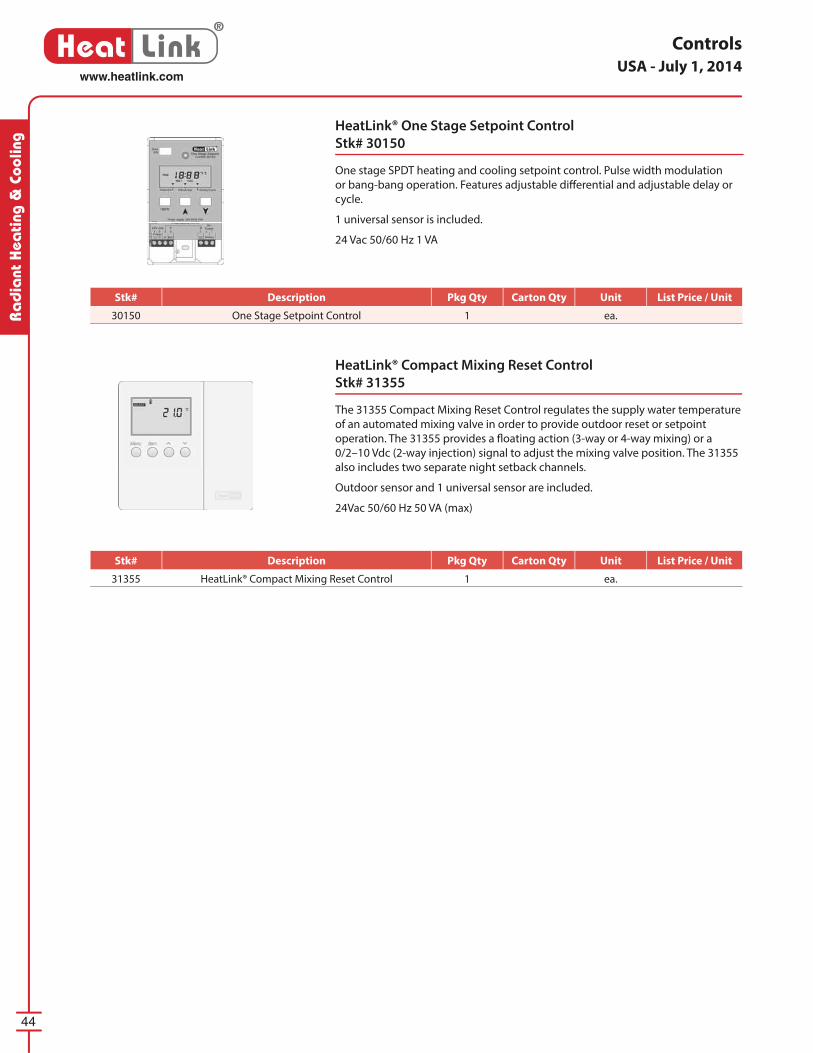
44
®
Heat Linkwww.heatlink.com
Ra
dia
nt H
eati
ng &
Coo
ling
Controls
HeatLink® One Stage Setpoint Control
Stk# 30150
One stage SPDT heating and cooling setpoint control. Pulse width modulation
or bang-bang operation. Features adjustable diff erential and adjustable delay or
cycle.
1 universal sensor is included.
24 Vac 50/60 Hz 1 VA
HeatLink® Compact Mixing Reset Control
Stk# 31355
The 31355 Compact Mixing Reset Control regulates the supply water temperature
of an automated mixing valve in order to provide outdoor reset or setpoint
operation. The 31355 provides a fl oating action (3-way or 4-way mixing) or a
0/2–10 Vdc (2-way injection) signal to adjust the mixing valve position. The 31355
also includes two separate night setback channels.
Outdoor sensor and 1 universal sensor are included.
24Vac 50/60 Hz 50 VA (max)
USA - July 1, 2014
Stk# Description Pkg Qty Carton Qty Unit List Price / Unit
30150 One Stage Setpoint Control 1 ea.
Stk# Description Pkg Qty Carton Qty Unit List Price / Unit
31355 HeatLink® Compact Mixing Reset Control 1 ea.
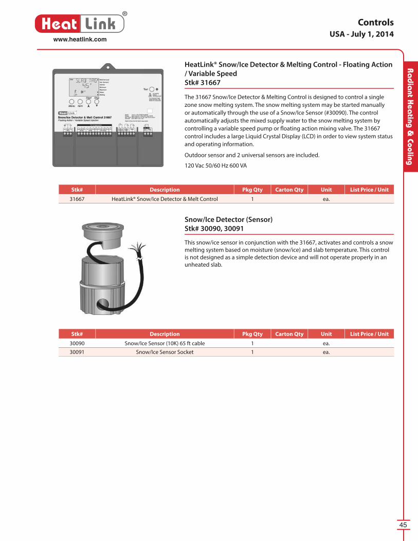
45
®
Heat Linkwww.heatlink.com
Ra
dia
nt Hea
ting & Cooling
Controls
HeatLink® Snow/Ice Detector & Melting Control - Floating Action
/ Variable Speed
Stk# 31667
The 31667 Snow/Ice Detector & Melting Control is designed to control a single
zone snow melting system. The snow melting system may be started manually
or automatically through the use of a Snow/Ice Sensor (#30090). The control
automatically adjusts the mixed supply water to the snow melting system by
controlling a variable speed pump or fl oating action mixing valve. The 31667
control includes a large Liquid Crystal Display (LCD) in order to view system status
and operating information.
Outdoor sensor and 2 universal sensors are included.
120 Vac 50/60 Hz 600 VA
Snow/Ice Detector (Sensor)
Stk# 30090, 30091
This snow/ice sensor in conjunction with the 31667, ac ti vates and con trols a snow
melting system based on moisture (snow/ice) and slab tem per a ture. This control
is not designed as a simple de tec tion device and will not operate properly in an
un heat ed slab.
USA - July 1, 2014
Stk# Description Pkg Qty Carton Qty Unit List Price / Unit
31667 HeatLink® Snow/Ice Detector & Melt Control 1 ea.
Stk# Description Pkg Qty Carton Qty Unit List Price / Unit
30090 Snow/Ice Sensor (10K) 65 ft cable 1 ea.
30091 Snow/Ice Sensor Socket 1 ea.
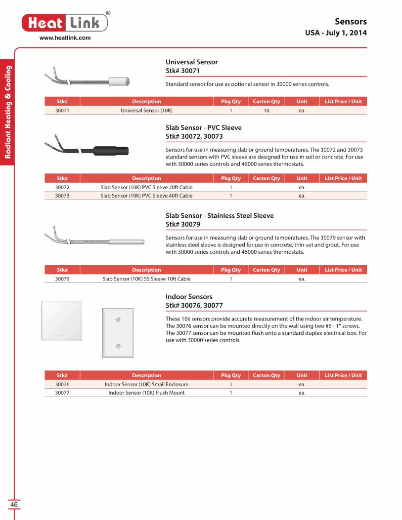
46
®
Heat Linkwww.heatlink.com
Ra
dia
nt H
eati
ng &
Coo
ling
Universal Sensor
Stk# 30071
Standard sensor for use as optional sensor in 30000 series controls.
Slab Sensor - PVC Sleeve
Stk# 30072, 30073
Sensors for use in measuring slab or ground temperatures. The 30072 and 30073
standard sensors with PVC sleeve are designed for use in soil or concrete. For use
with 30000 series controls and 46000 series thermostats.
Slab Sensor - Stainless Steel Sleeve
Stk# 30079
Sensors for use in measuring slab or ground temperatures. The 30079 sensor with
stainless steel sleeve is designed for use in concrete, thin-set and grout. For use
with 30000 series controls and 46000 series thermostats.
Sensors
Indoor Sensors
Stk# 30076, 30077
These 10k sensors provide accurate measurement of the indoor air tem per a ture.
The 30076 sensor can be mounted directly on the wall using two #6 - 1" screws.
The 30077 sensor can be mounted fl ush onto a stan dard duplex electrical box. For
use with 30000 series controls.
USA - July 1, 2014
Stk# Description Pkg Qty Carton Qty Unit List Price / Unit
30076 Indoor Sensor (10K) Small Enclosure 1 ea.
30077 Indoor Sensor (10K) Flush Mount 1 ea.
Stk# Description Pkg Qty Carton Qty Unit List Price / Unit
30071 Universal Sensor (10K) 1 10 ea.
Stk# Description Pkg Qty Carton Qty Unit List Price / Unit
30072 Slab Sensor (10K) PVC Sleeve 20ft Cable 1 ea.
30073 Slab Sensor (10K) PVC Sleeve 40ft Cable 1 ea.
Stk# Description Pkg Qty Carton Qty Unit List Price / Unit
30079 Slab Sensor (10K) SS Sleeve 10ft Cable 1 ea.
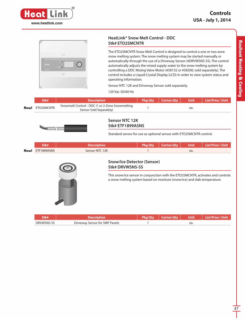
47
®
Heat Linkwww.heatlink.com
Ra
dia
nt Hea
ting & Cooling
Controls
Sensor NTC 12K
Stk# ETF1899ASNS
Standard sensor for use as optional sensor with ETO2SMCNTR control.
HeatLink® Snow Melt Control - DDC
Stk# ETO2SMCNTR
The ETO2SMCNTR Snow Melt Control is designed to control a one or two zone
snow melting system. The snow melting system may be started manually or
automatically through the use of a Driveway Sensor (#DRVWSNS-SS). The control
automatically adjusts the mixed supply water to the snow melting system by
controlling a DDC Mixing Valve Motor (#58132 or #58300; sold separately). The
control includes a Liquid Crystal Display (LCD) in order to view system status and
operating information.
Sensor NTC 12K and Driveway Sensor sold separately.
120 Vac 50/60 Hz
Snow/Ice Detector (Sensor)
Stk# DRVWSNS-SS
This snow/ice sensor in conjunction with the ETO2SMCNTR, ac ti vates and con trols
a snow melting system based on moisture (snow/ice) and slab tem per a ture.
USA - July 1, 2014
Stk# Description Pkg Qty Carton Qty Unit List Price / Unit
New! ETO2SMCNTRSnowmelt Control - DDC (1 or 2-Zone Snowmelting
Sensor Sold Separately)1 ea.
Stk# Description Pkg Qty Carton Qty Unit List Price / Unit
New! ETF1899ASNS Sensor NTC 12K 1 ea.
Stk# Description Pkg Qty Carton Qty Unit List Price / Unit
DRVWSNS-SS Driveway Sensor for SMP Panels 1 ea.
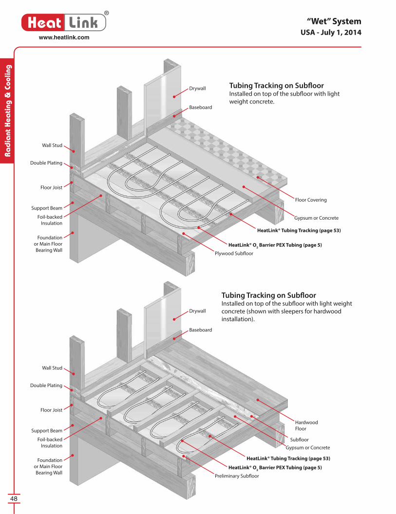
48
®
Heat Linkwww.heatlink.com
Ra
dia
nt H
eati
ng &
Coo
ling
“Wet” SystemUSA - July 1, 2014
Tubing Tracking on Subfl oorInstalled on top of the subfl oor with light
weight concrete.
Plywood Subfl oor
Preliminary Subfl oor
HeatLink® O2 Barrier PEX Tubing (page 5)
HeatLink® O2 Barrier PEX Tubing (page 5)
Subfl oor
Gypsum or Concrete
Gypsum or Concrete
Floor Covering
Hardwood
Floor
HeatLink® Tubing Tracking (page 53)
HeatLink® Tubing Tracking (page 53)
Baseboard
Baseboard
Drywall
Drywall
Wall Stud
Wall Stud
Double Plating
Double Plating
Floor Joist
Floor Joist
Support Beam
Support Beam
Foil-backed
Insulation
Foil-backed
Insulation
Foundation
or Main Floor
Bearing Wall
Foundation
or Main Floor
Bearing Wall
Tubing Tracking on Subfl oorInstalled on top of the subfl oor with light weight
concrete (shown with sleepers for hardwood
installation).
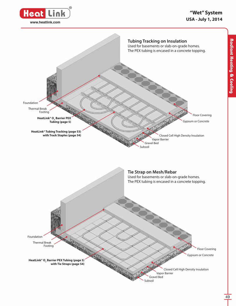
49
®
Heat Linkwww.heatlink.com
Ra
dia
nt Hea
ting & Cooling
“Wet” SystemUSA - July 1, 2014
Tubing Tracking on InsulationUsed for basements or slab-on-grade homes.
The PEX tubing is encased in a concrete topping.
Tie Strap on Mesh/RebarUsed for basements or slab-on-grade homes.
The PEX tubing is encased in a concrete topping.
Foundation
Footing
HeatLink® O2 Barrier PEX
Tubing (page 5)
Gravel Bed
Subsoil
Closed Cell High Density Insulation
Vapor Barrier
Gypsum or Concrete
Floor Covering
HeatLink® Tubing Tracking (page 53)
with Track Staples (page 54)
Thermal Break
Foundation
Footing
HeatLink® O2 Barrier PEX Tubing (page 5)
with Tie Straps (page 54)
Gravel Bed
Subsoil
Closed Cell High Density Insulation
Vapor Barrier
Gypsum or Concrete
Floor Covering
Thermal Break

®
Heat Link
• Dry system that eliminates the “pain in the neck” of overhead work
• No structural changes required• Ideal for retrofi ts or remodeling• Inexpensive components keep material costs low
DryAbove™ components:1 EndBend™
2 SpacerClip™
3 Heat Transfer Plate4 1⁄2” PEX Tubing
DryAbove™ System
2
2
2
3
3
3
41
1
14
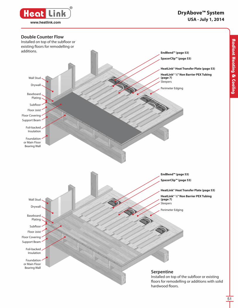
51
®
Heat Linkwww.heatlink.com
Ra
dia
nt Hea
ting & Cooling
DryAbove™ SystemUSA - July 1, 2014
Double Counter FlowInstalled on top of the subfl oor or
existing fl oors for remodelling or
additions.
SerpentineInstalled on top of the subfl oor or existing
fl oors for remodelling or additions with solid
hardwood fl oors.
Wall Stud
Wall Stud
Drywall
Drywall
Baseboard
Baseboard
Plating
Plating
Subfl oor
Subfl oor
Floor Joist
Floor Joist
Support Beam
Support Beam
Floor Covering
Floor Covering
Foil-backed
Insulation
Foil-backed
Insulation
Foundation
or Main Floor
Bearing Wall
Foundation
or Main Floor
Bearing Wall
EndBend™ (page 53)
EndBend™ (page 53)
HeatLink® Heat Transfer Plate (page 53)
HeatLink® Heat Transfer Plate (page 53)
SpacerClip™ (page 53)
SpacerClip™ (page 53)
HeatLink® 1⁄2" Non Barrier PEX Tubing (page 7)
HeatLink® 1⁄2" Non Barrier PEX Tubing (page 7)
Sleepers
Sleepers
Perimeter Edging
Perimeter Edging
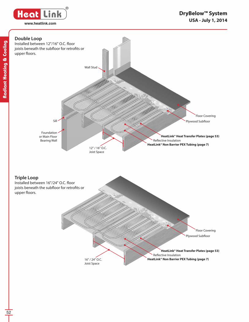
52
®
Heat Linkwww.heatlink.com
Ra
dia
nt H
eati
ng &
Coo
ling
DryBelow™ SystemUSA - July 1, 2014
Double LoopInstalled between 12"/16" O.C. fl oor
joists beneath the subfl oor for retrofi ts or
upper fl oors.
Triple LoopInstalled between 16"/24" O.C. fl oor
joists beneath the subfl oor for retrofi ts or
upper fl oors.
Floor Covering
Floor Covering
Plywood Subfl oor
Plywood Subfl oor
HeatLink® Non Barrier PEX Tubing (page 7)
HeatLink® Non Barrier PEX Tubing (page 7)
HeatLink® Heat Transfer Plates (page 53)
HeatLink® Heat Transfer Plates (page 53)
Refl ective Insulation
Refl ective Insulation
12" / 16" O.C.
Joist Space
16" / 24" O.C.
Joist Space
Sill
Foundation
or Main Floor
Bearing Wall
Wall Stud
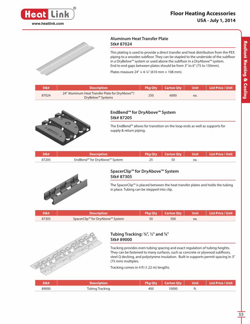
53
®
Heat Linkwww.heatlink.com
Ra
dia
nt Hea
ting & Cooling
Floor Heating Accessories
EndBend™ for DryAbove™ System
Stk# 87205
The EndBend™ allows for transition on the loop ends as well as supports for
supply & return piping.
Aluminum Heat Transfer Plate
Stk# 87024
This plating is used to provide a direct transfer and heat dis tri bu tion from the PEX
piping to a wooden subfl oor. They can be stapled to the underside of the subfl oor
in a DryBelow™ system or used above the subfl oor in a DryAbove™ system.
End to end gaps between plates should be from 3" to 6" (75 to 150mm).
Plates measure 24" × 4-1⁄4" (610 mm × 108 mm).
Tubing Tracking: 3⁄8", 1⁄2" and 5⁄8"
Stk# 89000
Tracking provides even tubing spacing and exact reg u la tion of tubing heights.
They can be fastened to many surfaces, such as concrete or plywood subfl oors,
steel Q deck ing, and polystyrene in su la tion. Built in sup ports permit spacing in 3"
(75 mm) multiples.
Tracking comes in 4 ft (1.22 m) lengths.
SpacerClip™ for DryAbove™ System
Stk# 87305
The SpacerClip™ is placed between the heat transfer plates and holds the tubing
in place. Tubing can be stepped into clip.
USA - July 1, 2014
Stk# Description Pkg Qty Carton Qty Unit List Price / Unit
8702424" Aluminum Heat Transfer Plate for DryAbove™/
DryBelow™ Systems250 6000 ea.
Stk# Description Pkg Qty Carton Qty Unit List Price / Unit
87205 EndBend™ for DryAbove™ System 25 50 ea.
Stk# Description Pkg Qty Carton Qty Unit List Price / Unit
87305 SpacerClip™ for DryAbove™ System 50 500 ea.
Stk# Description Pkg Qty Carton Qty Unit List Price / Unit
89000 Tubing Tracking 400 10000 ft.
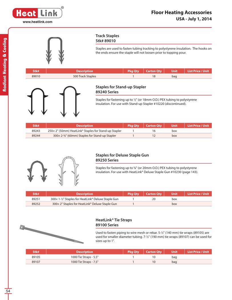
54
®
Heat Linkwww.heatlink.com
Ra
dia
nt H
eati
ng &
Coo
ling
Floor Heating Accessories
HeatLink® Tie Straps
89100 Series
Used to fasten piping to wire mesh or rebar. 5-1⁄2" (140 mm) tie wraps (89105) are
used for smaller diameter tubing. 7-1⁄2" (190 mm) tie wraps (89107) can be used for
sizes up to 1".
Staples for Stand-up Stapler
89240 Series
Staples for fastening up to 1⁄2" (or 18mm O.D.) PEX tubing to polystyrene
insulation. For use with Stand-up Stapler #10220 (discontinued).
Track Staples
Stk# 89010
Staples are used to fasten tubing tracking to polystyrene insulation. The hooks on
the ends ensure the staple will not loosen prior to topping pour.
Staples for Deluxe Staple Gun
89250 Series
Staples for fastening up to 5⁄8" (or 20mm O.D.) PEX tubing to polystyrene
insulation. For use with HeatLink® Deluxe Staple Gun #10230 (page 143).
USA - July 1, 2014
Stk# Description Pkg Qty Carton Qty Unit List Price / Unit
89010 500 Track Staples 1 18 bag
Stk# Description Pkg Qty Carton Qty Unit List Price / Unit
89243 250× 2" (50mm) HeatLink® Staples for Stand-up Stapler 1 16 box
89244 300× 2-3⁄8" (60mm) Staples for Stand-up Stapler 1 12 box
Stk# Description Pkg Qty Carton Qty Unit List Price / Unit
89251 300× 1-1⁄2" Staples for HeatLink® Deluxe Staple Gun 1 20 box
89252 300× 2" Staples for HeatLink® Deluxe Staple Gun 1 box
Stk# Description Pkg Qty Carton Qty Unit List Price / Unit
89105 1000 Tie Straps - 5.5" 1 10 bag
89107 1000 Tie Straps - 7.5" 1 10 bag
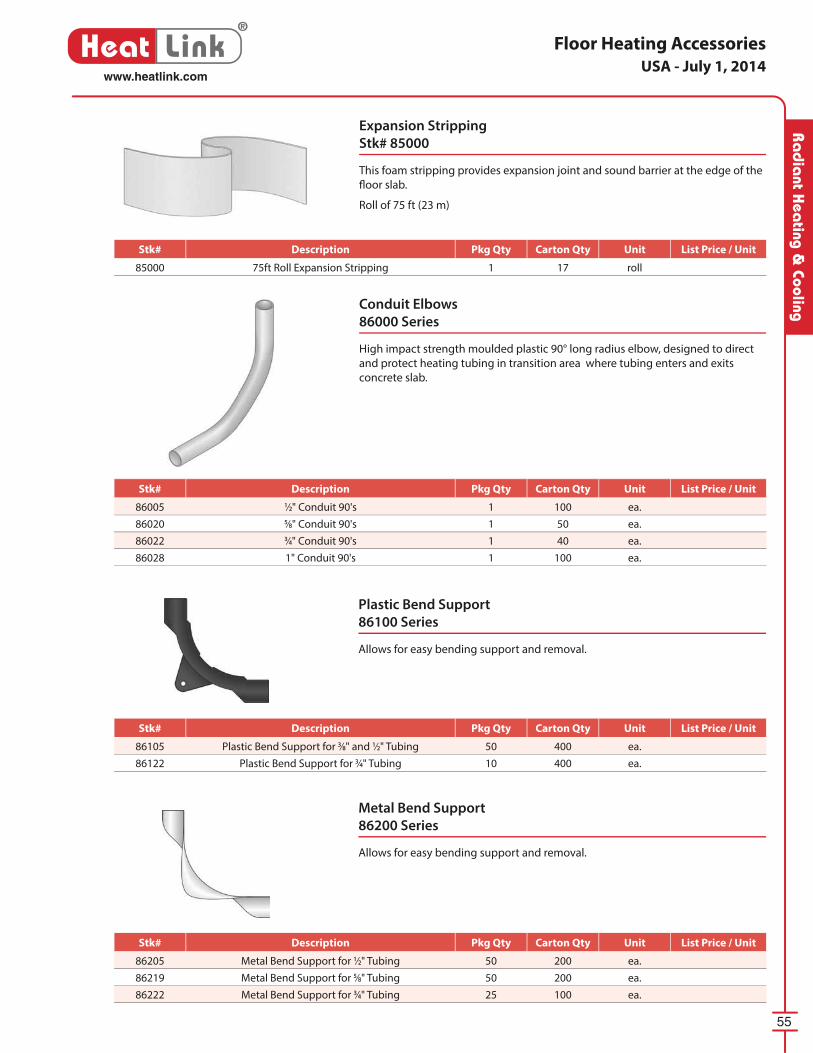
55
®
Heat Linkwww.heatlink.com
Ra
dia
nt Hea
ting & Cooling
Expansion Stripping
Stk# 85000
This foam stripping provides expansion joint and sound barrier at the edge of the
fl oor slab.
Roll of 75 ft (23 m)
Conduit Elbows
86000 Series
High impact strength moulded plastic 90° long radius elbow, designed to direct
and protect heating tubing in transition area where tubing enters and exits
concrete slab.
Floor Heating Accessories
Plastic Bend Support
86100 Series
Allows for easy bending support and removal.
Metal Bend Support
86200 Series
Allows for easy bending support and removal.
USA - July 1, 2014
Stk# Description Pkg Qty Carton Qty Unit List Price / Unit
86005 1⁄2" Conduit 90's 1 100 ea.
86020 5⁄8" Conduit 90's 1 50 ea.
86022 3⁄4" Conduit 90's 1 40 ea.
86028 1" Conduit 90's 1 100 ea.
Stk# Description Pkg Qty Carton Qty Unit List Price / Unit
85000 75ft Roll Expansion Stripping 1 17 roll
Stk# Description Pkg Qty Carton Qty Unit List Price / Unit
86105 Plastic Bend Support for 3⁄8" and 1⁄2" Tubing 50 400 ea.
86122 Plastic Bend Support for 3⁄4" Tubing 10 400 ea.
Stk# Description Pkg Qty Carton Qty Unit List Price / Unit
86205 Metal Bend Support for 1⁄2" Tubing 50 200 ea.
86219 Metal Bend Support for 5⁄8" Tubing 50 200 ea.
86222 Metal Bend Support for 3⁄4" Tubing 25 100 ea.
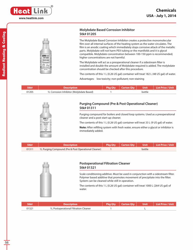
56
®
Heat Linkwww.heatlink.com
Ra
dia
nt H
eati
ng &
Coo
ling
Molybdate Based Corrosion Inhibitor
Stk# 01205
The Molybdate Based Corrosion Inhibitor creates a protective monomolecular
fi lm over all internal surfaces of the heating system as the water circulates. The
fi lm is an anodic coating which immediately stops corrosive attack of the metallic
parts. Molybdate will not harm PEX tubing or the manifolds and it is glycol
compatible. Molybdate concentration between 100-150 ppm is recommended;
higher concentrations are not harmful.
The Molybdate will act as a preoperational cleaner if a sidestream fi lter is
installed and double the amount of Molybdate required is added. The molybdate
concentration should be checked after this procedure.
The contents of this 1 L (0.26 US gal) container will treat 182 L (48 US gal) of water.
Advantages: low toxicity; non-pollutant; non-staining
Purging Compound (Pre & Post Operational Cleaner)
Stk# 01311
Purging compound for boilers and closed loop systems. Used as a preoperational
cleaner and a post start-up cleaner.
The contents of this 1 L (0.26 US gal) container will treat 33 L (9 US gal) of water.
Note: After refi lling system with fresh water, ensure either a glycol or inhibitor is
immediately added.
Postoperational Filtration Cleaner
Stk# 01321
Scale conditioning additive. Must be used in conjunction with a sidestream fi lter.
Polymer based additive that promotes movement of precipitate into the fi lter.
System can be cleaned while still in operation.
The contents of this 1 L (0.26 US gal) container will treat 1000 L (264 US gal) of
water.
ChemicalsUSA - July 1, 2014
Stk# Description Pkg Qty Carton Qty Unit List Price / Unit
01321 1L Postoperational Filtration Cleaner 1 L
Stk# Description Pkg Qty Carton Qty Unit List Price / Unit
01205 1L Corrosion Inhibitor (Molybdate Based) 1 bottle
Stk# Description Pkg Qty Carton Qty Unit List Price / Unit
01311 1L Purging Compound (Pre & Post Operational Cleaner) 1 bottle
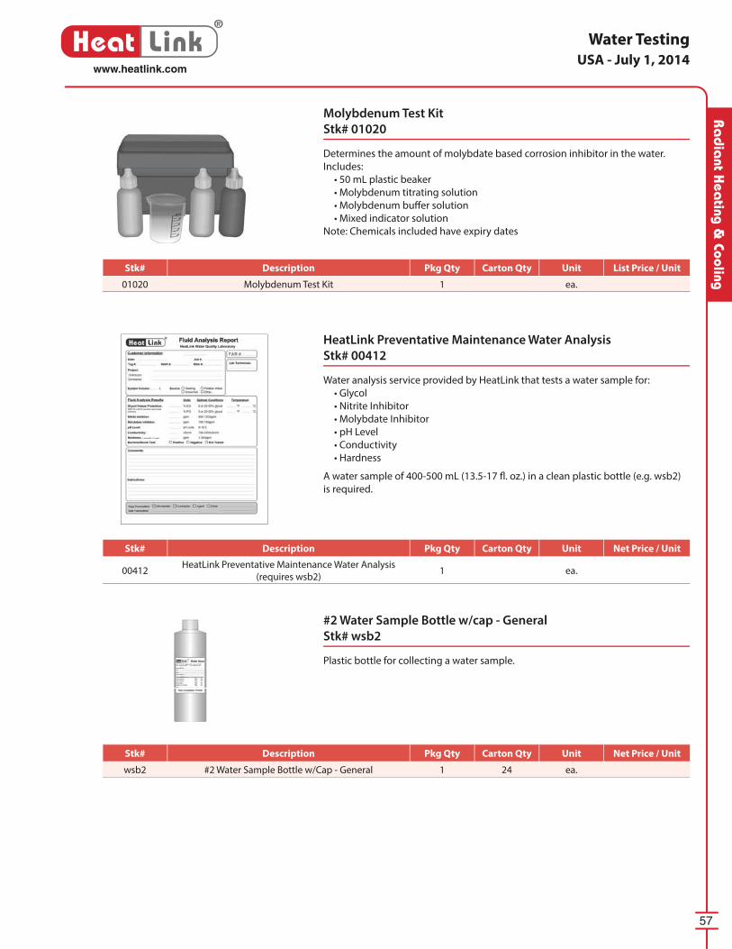
57
®
Heat Linkwww.heatlink.com
Ra
dia
nt Hea
ting & Cooling
Water Testing
Molybdenum Test Kit
Stk# 01020
Determines the amount of molybdate based corrosion inhibitor in the water.
Includes:
• 50 mL plastic beaker
• Molybdenum titrating solution
• Molybdenum buff er solution
• Mixed indicator solution
Note: Chemicals included have expiry dates
HeatLink Preventative Maintenance Water Analysis
Stk# 00412
Water analysis service provided by HeatLink that tests a water sample for:
• Glycol
• Nitrite Inhibitor
• Molybdate Inhibitor
• pH Level
• Conductivity
• Hardness
A water sample of 400-500 mL (13.5-17 fl . oz.) in a clean plastic bottle (e.g. wsb2)
is required.
#2 Water Sample Bottle w/cap - General
Stk# wsb2
Plastic bottle for collecting a water sample.
USA - July 1, 2014
Stk# Description Pkg Qty Carton Qty Unit List Price / Unit
wsb2 #2 Water Sample Bottle w/Cap - General 1 24 ea.
Stk# Description Pkg Qty Carton Qty Unit List Price / Unit
01020 Molybdenum Test Kit 1 ea.
Stk# Description Pkg Qty Carton Qty Unit List Price / Unit
00412HeatLink Preventative Maintenance Water Analysis
(requires wsb2)1 ea.
Stk# Description Pkg Qty Carton Qty Unit Net Price / Unit
Stk# Description Pkg Qty Carton Qty Unit Net Price / Unit
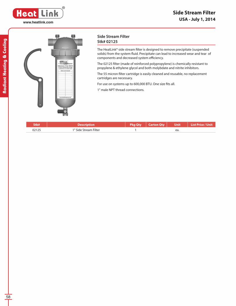
58
®
Heat Linkwww.heatlink.com
Ra
dia
nt H
eati
ng &
Coo
ling
Side Stream Filter
Side Stream Filter
Stk# 02125
The HeatLink® side stream fi lter is designed to remove precipitate (suspended
solids) from the system fl uid. Precipitate can lead to increased wear and tear of
components and decreased system effi ciency.
The 02125 fi lter (made of reinforced polypropylene) is chemically resistant to
propylene & ethylene glycol and both molybdate and nitrite inhibitors.
The 55 micron fi lter cartridge is easily cleaned and reusable, no replacement
cartridges are necessary.
For use on systems up to 600,000 BTU. One size fi ts all.
1" male NPT thread connections.
USA - July 1, 2014
Stk# Description Pkg Qty Carton Qty Unit List Price / Unit
02125 1" Side Stream Filter 1 ea.
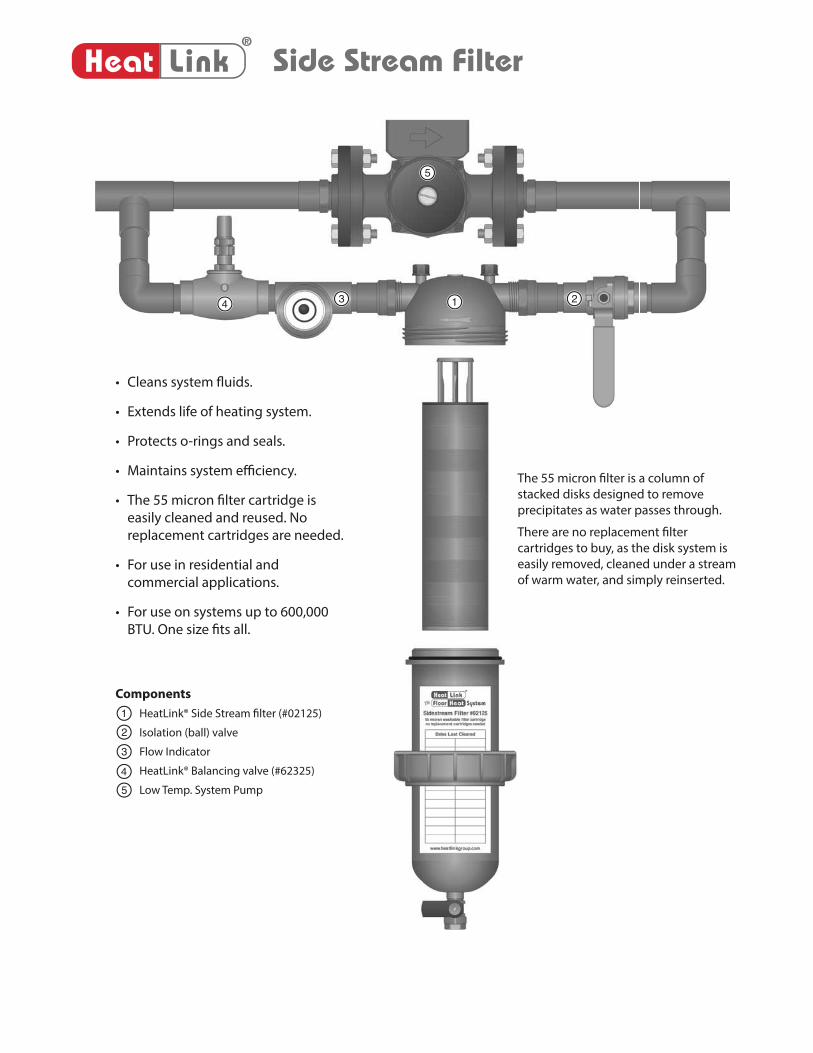
• Cleans system fl uids.
• Extends life of heating system.
• Protects o-rings and seals.
• Maintains system effi ciency.
• The 55 micron fi lter cartridge is
easily cleaned and reused. No
replacement cartridges are needed.
• For use in residential and
commercial applications.
• For use on systems up to 600,000
BTU. One size fi ts all.
The 55 micron fi lter is a column of
stacked disks designed to remove
precipitates as water passes through.
There are no replacement fi lter
cartridges to buy, as the disk system is
easily removed, cleaned under a stream
of warm water, and simply reinserted.
134 2
5
Components
HeatLink® Side Stream fi lter (#02125)
Isolation (ball) valve
Flow Indicator
HeatLink® Balancing valve (#62325)
Low Temp. System Pump
1
2
3
5
4
Side Stream Filter®
Heat Link
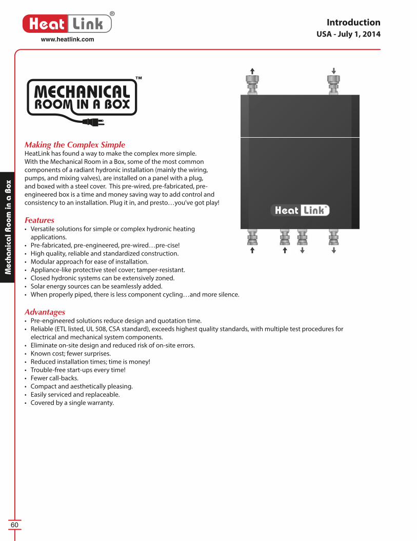
60
®
Heat Linkwww.heatlink.com
Mec
hani
cal R
oom
in a
Box
Introduction
Making the Complex SimpleHeatLink has found a way to make the complex more simple.
With the Mechanical Room in a Box, some of the most common
components of a radiant hydronic installation (mainly the wiring,
pumps, and mixing valves), are installed on a panel with a plug,
and boxed with a steel cover. This pre-wired, pre-fabricated, pre-
engineered box is a time and money saving way to add control and
consistency to an installation. Plug it in, and presto…you’ve got play!
Features• Versatile solutions for simple or complex hydronic heating
applications.
• Pre-fabricated, pre-engineered, pre-wired…pre-cise!
• High quality, reliable and standardized construction.
• Modular approach for ease of installation.
• Appliance-like protective steel cover; tamper-resistant.
• Closed hydronic systems can be extensively zoned.
• Solar energy sources can be seamlessly added.
• When properly piped, there is less component cycling…and more silence.
Advantages• Pre-engineered solutions reduce design and quotation time.
• Reliable (ETL listed, UL 508, CSA standard), exceeds highest quality standards, with multiple test procedures for
electrical and mechanical system components.
• Eliminate on-site design and reduced risk of on-site errors.
• Known cost; fewer surprises.
• Reduced installation times; time is money!
• Trouble-free start-ups every time!
• Fewer call-backs.
• Compact and aesthetically pleasing.
• Easily serviced and replaceable.
• Covered by a single warranty.
MECHANICALROOM IN A BOX
™
USA - July 1, 2014
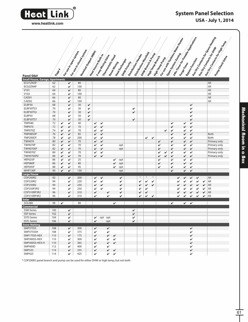
®
LinkHeat
61
www.heatlink.com
Mecha
nical R
oom in a
Box
System Panel Selection
Pag
e #
For
use
in o
pen
sys
tem
For
use
in c
lose
d s
yste
m
No
min
al O
utp
ut
(MB
H)
Hea
t So
urc
e B
uil
t-in
3-w
ay M
ixin
g V
alve
Ther
mo
stat
ic H
ead
Res
et M
ixin
gH
eat
Exch
ang
erD
HW
Pri
ori
tyD
istr
ibu
tio
n H
ead
er
Dis
trib
uti
on
Man
ifo
ld
DH
W B
ran
ch &
Pu
mp
Hig
h T
emp
Bra
nch
Hig
h T
emp
Pu
mp
For
use
wit
h T
ank
less
Wat
er H
eate
r
Op
en S
yste
m Z
on
ing
24
hr T
imer
for
Po
tab
le A
pp
lica
tio
ns
Pu
rge
Tim
erB
ypas
s Fu
nct
ion
Au
x D
ry C
on
tact
s fo
r Sp
ace
Hea
tin
g
Au
x D
ry C
on
tact
s fo
r D
HW
Au
x D
ry C
on
tact
s fo
r H
igh
Tem
p
Pu
mp
Ch
eck
Val
ve
Panel Stk#Small House, Garage, Apartments
ECO1ZN3P 62 ✔ 80 All
ECO2ZN4P 62 ✔ 100 All
V101 64 ✔ 80 All
V102 64 ✔ 100 All
CAD01 66 ✔ 80 All
CAD02 66 ✔ 100 All
ELBP30 68 ✔ 30 ✔ ✔
ELBP30TS3 70 ✔ 30 ✔ ✔ ✔
ELBP30TS5 70 ✔ 30 ✔ ✔ ✔
ELBP50 68 ✔ 50 ✔ ✔
ELBP50TS7 70 ✔ 50 ✔ ✔ ✔
TMP040 72 ✔ ✔ 40 ✔ ✔ ✔ ✔ ✔
TMP070 72 ✔ ✔ 70 ✔ ✔ ✔ ✔ ✔
TMP070Z 74 ✔ ✔ 70 ✔ ✔ ✔ ✔ ✔ ✔
TMP085DP 76 ✔ ✔ 85 ✔ ✔ ✔ ✔ ✔ Both
TMP200DT 78 ✔ ✔ 200 ✔ ✔ ✔ ✔ ✔ ✔ ✔ Both
TWH070 80 ✔ ✔ 70 ✔ ✔ ✔ ✔ ✔ ✔ Primary only
TWH070P 82 ✔ ✔ 70 ✔ ✔ opt ✔ ✔ ✔ ✔ Primary only
TWH070XP 82 ✔ ✔ 70 ✔ ✔ opt ✔ ✔ ✔ ✔ Primary only
TWH070Z 84 ✔ ✔ 70 ✔ ✔ ✔ ✔ ✔ ✔ ✔ Primary only
TWH070XPZ 84 ✔ ✔ 70 ✔ ✔ ✔ ✔ ✔ ✔ ✔ Primary only
HEP025P 86 ✔ ✔ 25 ✔ opt ✔ ✔ ✔ ✔
HEP080P 86 ✔ ✔ 80 ✔ opt ✔ ✔ ✔ ✔
HEP095P 88 ✔ ✔ 95 ✔ opt ✔ ✔ ✔ ✔
WHP130P 90 ✔ ✔ 130 opt ✔ ✔ ✔
Large House
CDP200R2 92 ✔ 200 ✔ ✔ ✔ * * * ✔ ✔ ✔ ✔ All
CDP220R2 94 ✔ 220 ✔ ✔ ✔ ✔ ✔ ✔ ✔ ✔ ✔ ✔ ✔ All
CDP250R2 94 ✔ 250 ✔ ✔ ✔ ✔ ✔ ✔ ✔ ✔ ✔ ✔ ✔ All
CDP250P3R2 94 ✔ 250 ✔ ✔ ✔ ✔ ✔ ✔ ✔ ✔ ✔ ✔ All
CDP310RP3R2 96 ✔ 310 ✔ ✔ ✔ ✔ ✔ ✔ ✔ ✔ ✔ ✔ All
CDP310RP4R2 96 ✔ 310 ✔ ✔ ✔ ✔ ✔ ✔ ✔ ✔ ✔ ✔ ✔ All
Solar
SOL080 98 ✔ 80 ✔ ✔ ✔ ✔
Commercial
SSM Series 100 ✔ ✔
SSP Series 102 ✔ ✔
SSTS Series 104 ✔ ✔ opt opt ✔
SSTL Series 106 ✔ ✔ opt ✔
Snow Melting
SMP375SS 108 ✔ 300 ✔ ✔ ✔
SMP375SSH 108 ✔ 375 ✔ ✔ ✔
SMP175SS-HEX 110 ✔ 175 ✔ ✔ ✔ ✔
SMP300SS-HEX 110 ✔ 300 ✔ ✔ ✔ ✔
SMP300SS-HEX-H 110 ✔ 365 ✔ ✔ ✔ ✔
SMP400D 112 ✔ 400 ✔ ✔ ✔
SMP335 114 ✔ 335 ✔ ✔ ✔ ✔
SMP425 114 ✔ 425 ✔ ✔ ✔ ✔
* CDP200R2 panel branch and pump can be used for either DHW or high temp, but not both
USA - July 1, 2014
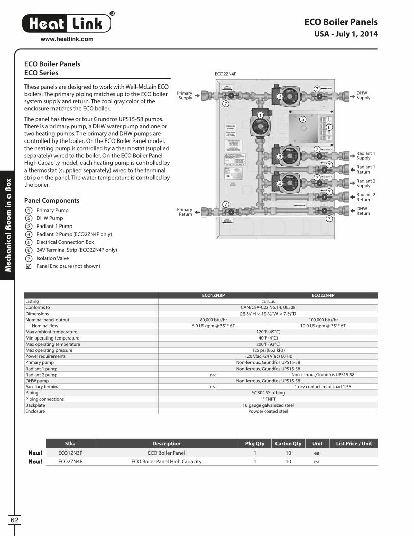
®
LinkHeat
62
www.heatlink.com
Mec
hani
cal R
oom
in a
Box
ECO Boiler Panels
ECO Series
These panels are designed to work with Weil-McLain ECO
boilers. The primary piping matches up to the ECO boiler
system supply and return. The cool gray color of the
enclosure matches the ECO boiler.
The panel has three or four Grundfos UPS15-58 pumps.
There is a primary pump, a DHW water pump and one or
two heating pumps. The primary and DHW pumps are
controlled by the boiler. On the ECO Boiler Panel model,
the heating pump is controlled by a thermostat (supplied
separately) wired to the boiler. On the ECO Boiler Panel
High Capacity model, each heating pump is controlled by
a thermostat (supplied separately) wired to the terminal
strip on the panel. The water temperature is controlled by
the boiler.
ECO1ZN3P ECO2ZN4P
Listing cETLus
Conforms to CAN/CSA-C22 No.14, UL508
Dimensions 26-1⁄4"H × 19-1⁄2"W × 7-1⁄8"DNominal panel output 80,000 btu/hr 100,000 btu/hr
Nominal fl ow 6.0 US gpm @ 35°F ΔT 10.0 US gpm @ 35°F ΔT
Max ambient temperature 120°F (49°C)
Min operating temperature 40°F (4°C)
Max operating temperature 200°F (93°C)
Max operating pressure 125 psi (862 kPa)
Power requirements 120 V(ac)/24 V(ac) 60 Hz
Primary pump Non-ferrous, Grundfos UPS15-58
Radiant 1 pump Non-ferrous, Grundfos UPS15-58
Radiant 2 pump n/a Non-ferrous,Grundfos UPS15-58
DHW pump Non-ferrous, Grundfos UPS15-58
Auxiliary terminal n/a 1 dry contact, max. load 1.5A
Piping 3⁄4" 304 SS tubing
Piping connections 1" FNPT
Backplate 16 gauge galvanized steel
Enclosure Powder coated steel
Panel Components
Primary Pump
DHW Pump
Radiant 1 Pump
Radiant 2 Pump (ECO2ZN4P only)
Electrical Connection Box
24V Terminal Strip (ECO2ZN4P only)
Isolation Valve
Panel Enclosure (not shown)
1
2
1
2
3
3
4
4
5
5
6
6
7
7
7
7
7
7
7
7
7
Primary Supply
Primary Return
DHWSupply
Radiant 1Supply
Radiant 1Return
Radiant 2Supply
Radiant 2Return
DHWReturn
ECO2ZN4P
USA - July 1, 2014
Stk# Description Pkg Qty Carton Qty Unit List Price / Unit
New! ECO1ZN3P ECO Boiler Panel 1 10 ea.
New! ECO2ZN4P ECO Boiler Panel High Capacity 1 10 ea.
ECO Boiler Panels
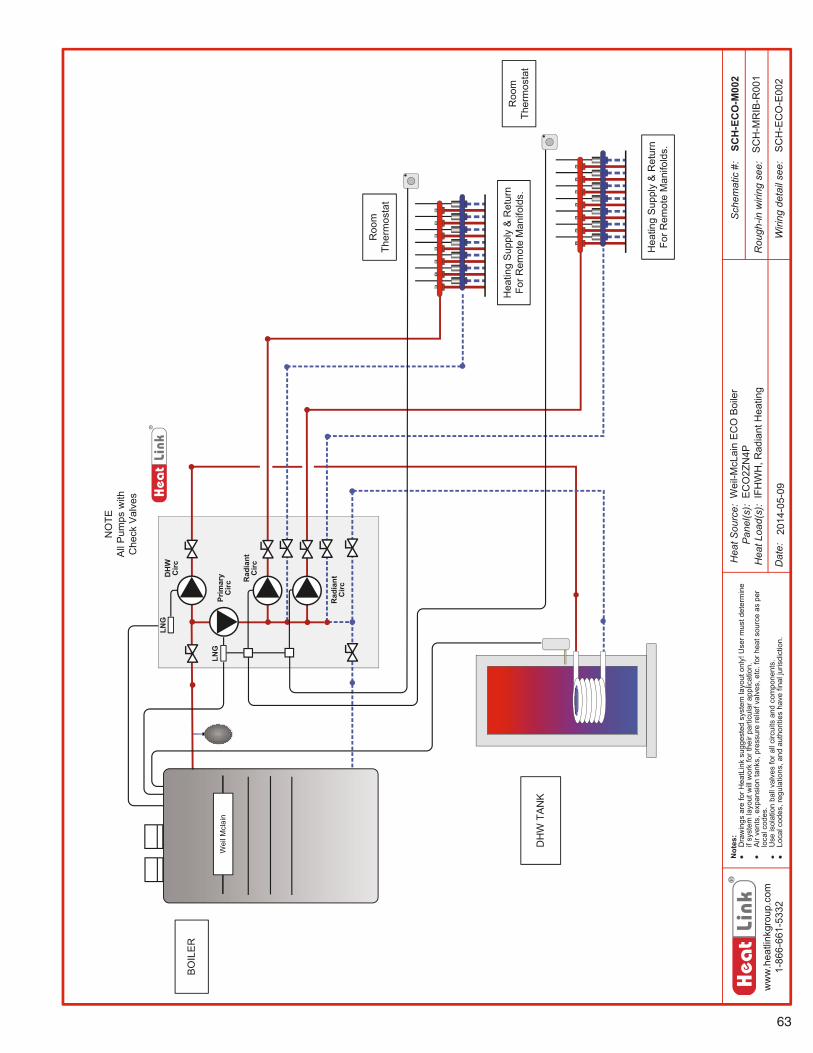
63
ww
w.h
eatli
nkgr
oup.
com
1-86
6-66
1-53
32
Hea
tSou
rce:
Pan
el(s
):H
eatL
oad(
s):
Sch
emat
ic#:
Dat
e:
Not
es:
ooD
raw
ings
are
forH
eatL
ink
sugg
este
dsy
stem
layo
uton
ly!U
serm
ustd
eter
min
eif
syst
emla
yout
will
wor
kfo
rthe
irpa
rticu
lara
pplic
atio
n.A
irve
nts,
expa
nsio
nta
nks,
pres
sure
relie
fval
ves,
etc.
forh
eats
ourc
eas
per
loca
lcod
es.
Use
isol
atio
nba
llva
lves
fora
llci
rcui
tsan
dco
mpo
nent
s.Lo
calc
odes
,reg
ulat
ions
,and
auth
oriti
esha
vefin
alju
risdi
ctio
n.
Rou
gh-in
wiri
ngse
e:
Wiri
ngde
tail
see:
Hea
ting
Sup
ply
&R
etur
nFo
rRem
ote
Man
ifold
s.
Roo
mTh
erm
osta
t
BO
ILE
R
DH
WTA
NK
Rad
iant
Circ
Prim
ary
Circ
DH
WC
ircLN
G
NO
TEA
llP
umps
with
Che
ckV
alve
s
LNG
Wei
lMcl
ain
Rad
iant
Circ
Hea
ting
Sup
ply
&R
etur
nFo
rRem
ote
Man
ifold
s.
Roo
mTh
erm
osta
t
SCH
-EC
O-M
002
2014
-05-
09S
CH
-EC
O-E
002
Wei
l-McL
ain
EC
OB
oile
rE
CO
2ZN
4PIF
HW
H,R
adia
ntH
eatin
gS
CH
-MR
IB-R
001
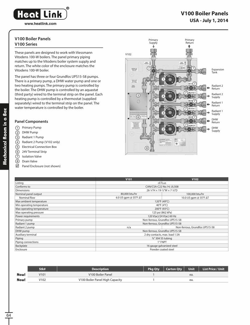
®
LinkHeat
64
www.heatlink.com
Mec
hani
cal R
oom
in a
Box
V100 Boiler Panels
V100 Series
These panels are designed to work with Viessmann
Vitodens 100-W boilers. The panel primary piping
matches up to the Vitodens boiler system supply and
return. The white color of the enclosure matches the
Vitodens 100-W boiler.
The panel has three or four Grundfos UPS15-58 pumps.
There is a primary pump, a DHW water pump and one or
two heating pumps. The primary pump is controlled by
the boiler. The DHW pump is controlled by an aquastat
(third party) wired to the terminal strip on the panel. Each
heating pump is controlled by a thermostat (supplied
separately) wired to the terminal strip on the panel. The
water temperature is controlled by the boiler.
Panel Components
Primary Pump
DHW Pump
Radiant 1 Pump
Radiant 2 Pump (V102 only)
Electrical Connection Box
24V Terminal Strip
Isolation Valve
Drain Valve
Panel Enclosure (not shown)
1
1
4
3
22
3
4
5
5
6
6
7
7 7
7
7
7
7
7
7
8
8
Primary Supply
Primary Return
DHWSupply
Radiant 2 Supply
Radiant 2Return
Radiant 1 Supply
Radiant 1Return
DHWReturn
ExpansionTank
V101 V102
Listing cETLus
Conforms to CAN/CSA-C22 No.14, UL508
Dimensions 26-1⁄4"H × 19-1⁄2"W × 7-1⁄8"D
Nominal panel output 80,000 btu/hr 100,000 btu/hr
Nominal fl ow 6.0 US gpm @ 35°F ΔT 10.0 US gpm @ 35°F ΔT
Max ambient temperature 120°F (49°C)
Min operating temperature 40°F (4°C)
Max operating temperature 200°F (93°C)
Max operating pressure 125 psi (862 kPa)
Power requirements 120 V(ac)/24 V(ac) 60 Hz
Primary pump Non-ferrous, Grundfos UPS15-58
Radiant 1 pump Non-ferrous, Grundfos UPS15-58
Radiant 2 pump n/a Non-ferrous, Grundfos UPS15-58
DHW pump Non-ferrous, Grundfos UPS15-58
Auxiliary terminal 2 dry contacts, max. load 1.5A
Piping 3⁄4" 304 SS tubing
Piping connections 1" FNPT
Backplate 16 gauge galvanized steel
Enclosure Powder coated steel
V102
USA - July 1, 2014
V100 Boiler Panels
Stk# Description Pkg Qty Carton Qty Unit List Price / Unit
New! V101 V100 Boiler Panel 1 ea.
New! V102 V100 Boiler Panel High Capacity 1 ea.
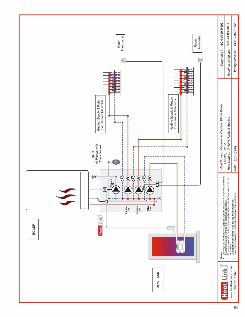
65
ww
w.h
eatli
nkgr
oup.
com
1-86
6-66
1-53
32
Hea
tSou
rce:
Pan
el(s
):H
eatL
oad(
s):
Sch
emat
ic#:
Dat
e:
Not
es:
Dra
win
gsar
efo
rHea
tLin
ksu
gges
ted
syst
emla
yout
only
!Use
rmus
tdet
erm
ine
ifsy
stem
layo
utw
illw
ork
fort
heir
parti
cula
rapp
licat
ion.
Air
vent
s,ex
pans
ion
tank
s,pr
essu
rere
liefv
alve
s,et
c.fo
rhea
tsou
rce
aspe
rlo
calc
odes
.U
seis
olat
ion
ball
valv
esfo
rall
circ
uits
and
com
pone
nts.
Loca
lcod
es,r
egul
atio
ns,a
ndau
thor
ities
have
final
juris
dict
ion.
Rou
gh-in
wiri
ngse
e:
Wiri
ngde
tail
see:
SCH
-V10
0-M
003
2014
-05-
09S
CH
-V10
0-E
002
Vie
ssm
ann
Vito
dens
100-
WB
oile
rV
102
IFH
WH
,Rad
iant
Hea
ting
SC
H-M
RIB
-R00
1
Hea
ting
Sup
ply
&R
etur
nFo
rRem
ote
Man
ifold
s.
Roo
mTh
erm
osta
t
BO
ILE
R
DH
WTA
NK
Rad
iant
Circ
Prim
ary
Circ
DH
WC
irc
NO
TEA
llP
umps
with
Che
ckV
alve
s
Rad
iant
Circ
Hea
ting
Sup
ply
&R
etur
nFo
rRem
ote
Man
ifold
s.
Roo
mTh
erm
osta
t
LNG
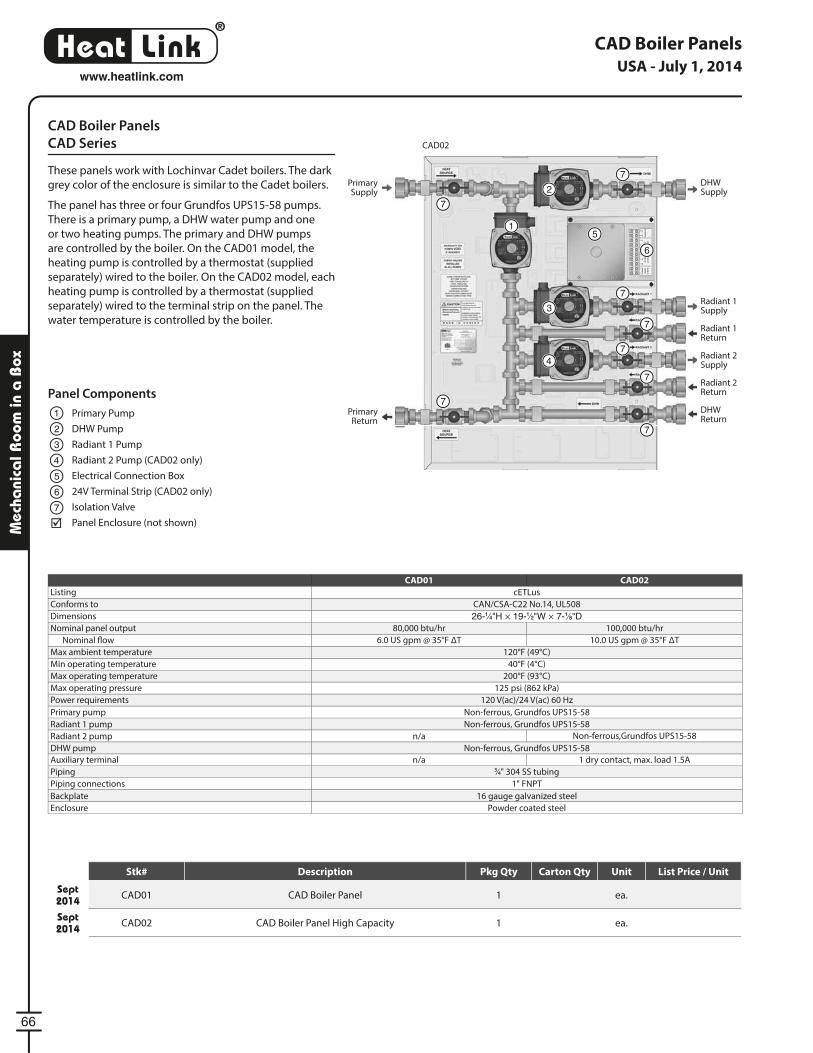
®
LinkHeat
66
www.heatlink.com
Mec
hani
cal R
oom
in a
Box
CAD Boiler Panels
CAD Series
These panels work with Lochinvar Cadet boilers. The dark
grey color of the enclosure is similar to the Cadet boilers.
The panel has three or four Grundfos UPS15-58 pumps.
There is a primary pump, a DHW water pump and one
or two heating pumps. The primary and DHW pumps
are controlled by the boiler. On the CAD01 model, the
heating pump is controlled by a thermostat (supplied
separately) wired to the boiler. On the CAD02 model, each
heating pump is controlled by a thermostat (supplied
separately) wired to the terminal strip on the panel. The
water temperature is controlled by the boiler.
CAD Boiler Panels
CAD01 CAD02
Listing cETLus
Conforms to CAN/CSA-C22 No.14, UL508
Dimensions 26-1⁄4"H × 19-1⁄2"W × 7-1⁄8"DNominal panel output 80,000 btu/hr 100,000 btu/hr
Nominal fl ow 6.0 US gpm @ 35°F ΔT 10.0 US gpm @ 35°F ΔT
Max ambient temperature 120°F (49°C)
Min operating temperature 40°F (4°C)
Max operating temperature 200°F (93°C)
Max operating pressure 125 psi (862 kPa)
Power requirements 120 V(ac)/24 V(ac) 60 Hz
Primary pump Non-ferrous, Grundfos UPS15-58
Radiant 1 pump Non-ferrous, Grundfos UPS15-58
Radiant 2 pump n/a Non-ferrous,Grundfos UPS15-58
DHW pump Non-ferrous, Grundfos UPS15-58
Auxiliary terminal n/a 1 dry contact, max. load 1.5A
Piping 3⁄4" 304 SS tubing
Piping connections 1" FNPT
Backplate 16 gauge galvanized steel
Enclosure Powder coated steel
Panel Components
Primary Pump
DHW Pump
Radiant 1 Pump
Radiant 2 Pump (CAD02 only)
Electrical Connection Box
24V Terminal Strip (CAD02 only)
Isolation Valve
Panel Enclosure (not shown)
1
2
1
2
3
3
4
4
5
5
6
6
7
7
7
7
7
7
7
7
7
Primary Supply
Primary Return
DHWSupply
Radiant 1Supply
Radiant 1Return
Radiant 2Supply
Radiant 2Return
DHWReturn
CAD02
USA - July 1, 2014
Stk# Description Pkg Qty Carton Qty Unit List Price / Unit
Sept 2014 CAD01 CAD Boiler Panel 1 ea.
Sept 2014 CAD02 CAD Boiler Panel High Capacity 1 ea.
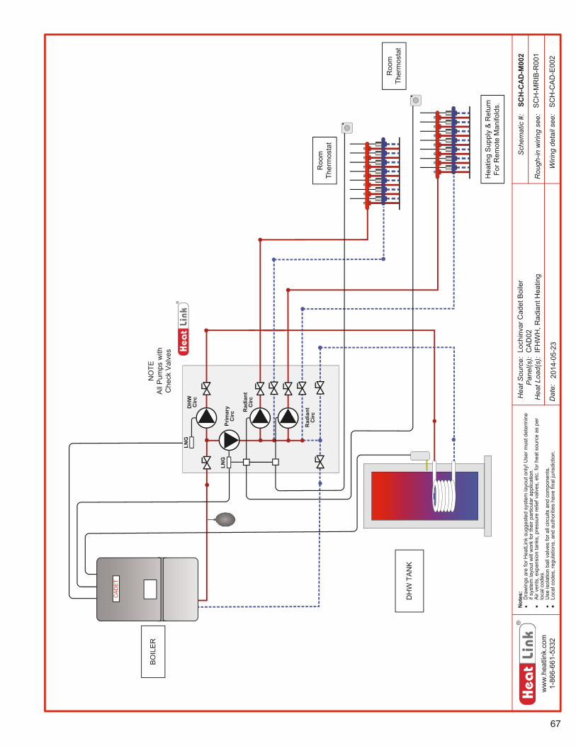
67
ww
w.h
eatli
nk.c
om1-
866-
661-
5332
Hea
tSou
rce:
Pan
el(s
):H
eatL
oad(
s):
Sch
emat
ic#:
Dat
e:
Not
es:
ooD
raw
ings
are
forH
eatL
ink
sugg
este
dsy
stem
layo
uton
ly!U
serm
ustd
eter
min
eif
syst
emla
yout
will
wor
kfo
rthe
irpa
rticu
lara
pplic
atio
n.A
irve
nts,
expa
nsio
nta
nks,
pres
sure
relie
fval
ves,
etc.
forh
eats
ourc
eas
per
loca
lcod
es.
Use
isol
atio
nba
llva
lves
fora
llci
rcui
tsan
dco
mpo
nent
s.Lo
calc
odes
,reg
ulat
ions
,and
auth
oriti
esha
vefin
alju
risdi
ctio
n.
Rou
gh-in
wiri
ngse
e:
Wiri
ngde
tail
see:
SCH
-CA
D-M
002
2014
-05-
23S
CH
-CA
D-E
002
Loch
inva
rCad
etB
oile
rC
AD
02IF
HW
H,R
adia
ntH
eatin
gS
CH
-MR
IB-R
001
Hea
ting
Sup
ply
&R
etur
nFo
rRem
ote
Man
ifold
s.
Roo
mTh
erm
osta
t
BO
ILE
R
DH
WTA
NK
Rad
iant
Circ
Prim
ary
Circ
DH
WC
ircLN
G
NO
TEA
llP
umps
with
Che
ckV
alve
s
LNG
Rad
iant
Circ
Roo
mTh
erm
osta
t
CA
DE
T
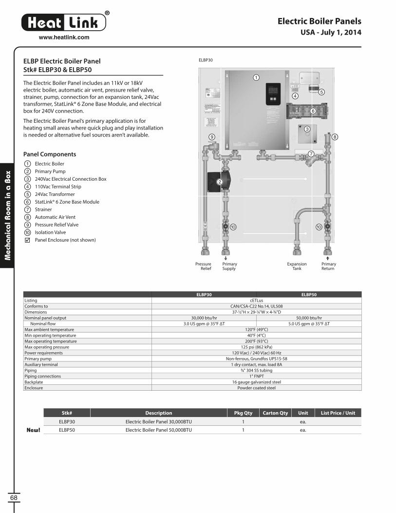
®
LinkHeat
68
www.heatlink.com
Mec
hani
cal R
oom
in a
Box
Electric Boiler Panels
ELBP Electric Boiler Panel
Stk# ELBP30 & ELBP50
The Electric Boiler Panel includes an 11kV or 18kV
electric boiler, automatic air vent, pressure relief valve,
strainer, pump, connection for an expansion tank, 24Vac
transformer, StatLink® 6 Zone Base Module, and electrical
box for 240V connection.
The Electric Boiler Panel’s primary application is for
heating small areas where quick plug and play installation
is needed or alternative fuel sources aren’t available.
ELBP30 ELBP50
Listing cETLus
Conforms to CAN/CSA-C22 No.14, UL508
Dimensions 37-1⁄2"H × 29-1⁄4"W × 4-3⁄4"D
Nominal panel output 30,000 btu/hr 50,000 btu/hr
Nominal fl ow 3.0 US gpm @ 35°F ΔT 5.0 US gpm @ 35°F ΔT
Max ambient temperature 120°F (49°C)
Min operating temperature 40°F (4°C)
Max operating temperature 200°F (93°C)
Max operating pressure 125 psi (862 kPa)
Power requirements 120 V(ac) / 240 V(ac) 60 Hz
Primary pump Non-ferrous, Grundfos UPS15-58
Auxiliary terminal 1 dry contact, max. load 8A
Piping 3⁄4" 304 SS tubing
Piping connections 1" FNPT
Backplate 16 gauge galvanized steel
Enclosure Powder coated steel
Panel Components
Electric Boiler
Primary Pump
240Vac Electrical Connection Box
110Vac Terminal Strip
24Vac Transformer
StatLink® 6 Zone Base Module
Strainer
Automatic Air Vent
Pressure Relief Valve
Isolation Valve
Panel Enclosure (not shown)
1
1
2
23
3
4
4
5
5
6
6
7
7
8
8
9
9
1010 10
ExpansionTank
Primary Supply
Primary Return
Pressure Relief
ELBP30
USA - July 1, 2014
Stk# Description Pkg Qty Carton Qty Unit List Price / Unit
ELBP30 Electric Boiler Panel 30,000BTU 1 ea.
New! ELBP50 Electric Boiler Panel 50,000BTU 1 ea.
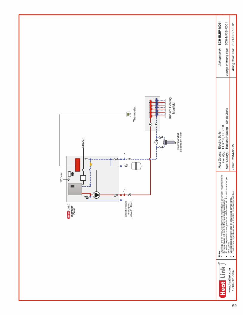
69
ww
w.h
eatli
nk.c
om1-
866-
661-
5332
Hea
tSou
rce:
Pan
el(s
):H
eatL
oad(
s):
Sch
emat
ic#:
Dat
e:
Not
es:
Dra
win
gsar
efo
rHea
tLin
ksu
gges
ted
syst
emla
yout
only
!Use
rmus
tdet
erm
ine
ifsy
stem
layo
utw
illw
ork
fort
heir
parti
cula
rapp
licat
ion.
Air
vent
s,ex
pans
ion
tank
s,pr
essu
rere
liefv
alve
s,et
c.fo
rhea
tsou
rce
aspe
rlo
calc
odes
.U
seis
olat
ion
ball
valv
esfo
rall
circ
uits
and
com
pone
nts.
Loca
lcod
es,r
egul
atio
ns,a
ndau
thor
ities
have
final
juris
dict
ion.
Rou
gh-in
wiri
ngse
e:
Wiri
ngde
tail
see:
ELB
P30/
50Pa
nel
Ext
end
pres
sure
relie
fpip
eto
with
in6"
offlo
or.
240V
ac
120V
ac
SCH
-ELB
P-M
001
2014
-05-
15
SC
H-M
RIB
-R00
1
SC
H-E
LBP
-E00
1
Ele
ctric
Boi
ler
ELB
P30
,ELB
P50
Rad
iant
Hea
ting–
Sin
gle
Zone
Ther
mos
tat
Rad
iant
Hea
ting
Man
ifold
Rec
omm
ende
dS
ides
tream
Filte
r

®
LinkHeat
70
www.heatlink.com
Mec
hani
cal R
oom
in a
Box
Electric Boiler Panels with Manifold
ELBP Electric Boiler Panel with Manifold
Stk# ELBP30TS3, ELBP30TS5, & ELBP50TS7
The Electric Boiler Panel includes an 11kV or 18kV electric
boiler, automatic air vent, pressure relief valve, strainer,
pump, connection for an expansion tank, TwistSeal®
Multiport Mini Manifold, 24Vac transformer, StatLink®
6 Zone Base Module, and electrical box for 240V
connection.
The Electric Boiler Panel’s primary application is for
heating small areas where quick plug and play installation
is needed or alternative fuel sources aren’t available.
ELBP30TS3, ELBP30TS5 ELBP50TS7
Listing cETLus
Conforms to CAN/CSA-C22 No.14, UL508
Dimensions 37-1⁄2"H × 29-1⁄4"W × 4-3⁄4"DNominal panel output 30,000 btu/hr 50,000 btu/hr
Nominal fl ow 3.0 US gpm @ 35°F ΔT 5.0 US gpm @ 35°F ΔT
Max ambient temperature 120°F (49°C)
Min operating temperature 40°F (4°C)
Max operating temperature 200°F (93°C)
Max operating pressure 125 psi (862 kPa)
Power requirements 120 V(ac) / 240 V(ac) 60 Hz
Primary pump Non-ferrous, Grundfos UPS15-58
Auxiliary terminal 1 dry contact, max. load 8A
Piping 3⁄4" 304 SS tubing
Piping connections 1" FNPT
Backplate 16 Gauge galvanized steel
Enclosure Powder coated steel
Panel Components
Electric Boiler
Primary Pump
240Vac Electrical Connection Box
110Vac Terminal Strip
24Vac Transformer
StatLink® 6 Zone Base Module
Strainer
Automatic Air Vent
Pressure Relief Valve
Isolation Valve
TwistSeal® Mini Multiport Manifold
Thermometer
Hosebib
Panel Enclosure (not shown)
1
1
2
23
3
4
4
5
5
6
6
7
7
8
8
8
8
9
9
10
11
12
13
11
13
10
10
ExpansionTank
Pressure Relief
12
12
ELBP50TS7
USA - July 1, 2014
Stk# Description Pkg Qty Carton Qty Unit List Price / Unit
New! ELBP30TS3Electric Boiler Panel 30,000BTU with 3 Loop Twist Seal Mini
Multiport1 ea.
ELBP30TS5Electric Boiler Panel 30,000BTU with 5 Loop Twist Seal Mini
Multiport1 ea.
New! ELBP50TS7Electric Boiler Panel 50,000BTU with 7 Loop Twist Seal Mini
Multiport1 ea.
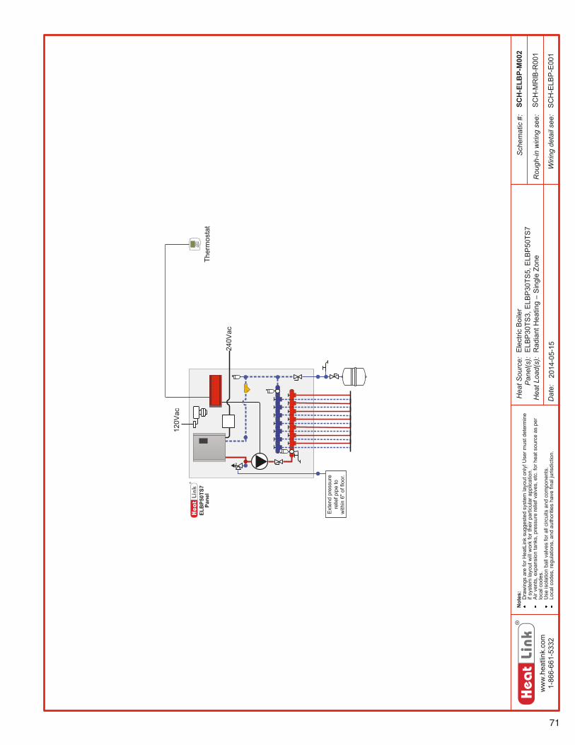
71
ww
w.h
eatli
nk.c
om1-
866-
661-
5332
Hea
tSou
rce:
Pan
el(s
):H
eatL
oad(
s):
Sch
emat
ic#:
Dat
e:
Not
es:
Dra
win
gsar
efo
rHea
tLin
ksu
gges
ted
syst
emla
yout
only
!Use
rmus
tdet
erm
ine
ifsy
stem
layo
utw
illw
ork
fort
heir
parti
cula
rapp
licat
ion.
Air
vent
s,ex
pans
ion
tank
s,pr
essu
rere
liefv
alve
s,et
c.fo
rhea
tsou
rce
aspe
rlo
calc
odes
.U
seis
olat
ion
ball
valv
esfo
rall
circ
uits
and
com
pone
nts.
Loca
lcod
es,r
egul
atio
ns,a
ndau
thor
ities
have
final
juris
dict
ion.
Rou
gh-in
wiri
ngse
e:
Wiri
ngde
tail
see:
ELB
P50T
S7Pa
nel
Ext
end
pres
sure
relie
fpip
eto
with
in6"
offlo
or.
240V
ac
120V
ac
SCH
-ELB
P-M
002
2014
-05-
15
SC
H-M
RIB
-R00
1
SC
H-E
LBP
-E00
1
Ele
ctric
Boi
ler
ELB
P30
TS3,
ELB
P30
TS5,
ELB
P50
TS7
Rad
iant
Hea
ting–
Sin
gle
ZoneTh
erm
osta
t
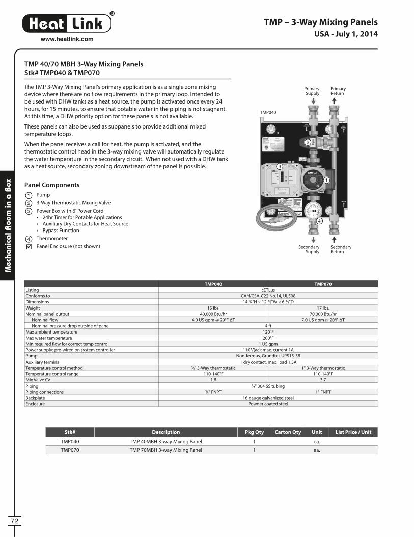
®
LinkHeat
72
www.heatlink.com
Mec
hani
cal R
oom
in a
Box
TMP 40/70 MBH 3-Way Mixing Panels
Stk# TMP040 & TMP070
The TMP 3-Way Mixing Panel’s primary application is as a single zone mixing
device where there are no fl ow requirements in the primary loop. Intended to
be used with DHW tanks as a heat source, the pump is activated once every 24
hours, for 15 minutes, to ensure that potable water in the piping is not stagnant.
At this time, a DHW priority option for these panels is not available.
These panels can also be used as subpanels to provide additional mixed
temperature loops.
When the panel receives a call for heat, the pump is activated, and the
thermostatic control head in the 3-way mixing valve will automatically regulate
the water temperature in the secondary circuit. When not used with a DHW tank
as a heat source, secondary zoning downstream of the panel is possible.
TMP – 3-Way Mixing Panels
TMP040
TMP040 TMP070
Listing cETLus
Conforms to CAN/CSA-C22 No.14, UL508
Dimensions 14-3⁄4"H × 12-1⁄2"W × 6-1⁄2"D
Weight 15 lbs. 17 lbs.
Nominal panel output 40,000 Btu/hr 70,000 Btu/hr
Nominal fl ow 4.0 US gpm @ 20°F ΔT 7.0 US gpm @ 20°F ΔT
Nominal pressure drop outside of panel 4 ft
Max ambient temperature 120°F
Max water temperature 200°F
Min required fl ow for correct temp control 1 US gpm
Power supply: pre-wired on system controller 110 V(ac); max. current 1A
Pump Non-ferrous, Grundfos UPS15-58
Auxiliary terminal 1 dry contact, max. load 1.5A
Temperature control method 3⁄4" 3-Way thermostatic 1" 3-Way thermostatic
Temperature control range 110-140°F 110-140°F
Mix Valve Cv 1.8 3.7
Piping 3⁄4" 304 SS tubing
Piping connections 3⁄4" FNPT 1" FNPT
Backplate 16 gauge galvanized steel
Enclosure Powder coated steel
1
4
Panel Components
Pump
3-Way Thermostatic Mixing Valve
Power Box with 6' Power Cord
• 24hr Timer for Potable Applications
• Auxiliary Dry Contacts for Heat Source
• Bypass Function
Thermometer
Panel Enclosure (not shown)
1
2
3
4
3
2
Primary Supply
Secondary Supply
Primary Return
Secondary Return
USA - July 1, 2014
Stk# Description Pkg Qty Carton Qty Unit List Price / Unit
TMP040 TMP 40MBH 3-way Mixing Panel 1 ea.
TMP070 TMP 70MBH 3-way Mixing Panel 1 ea.
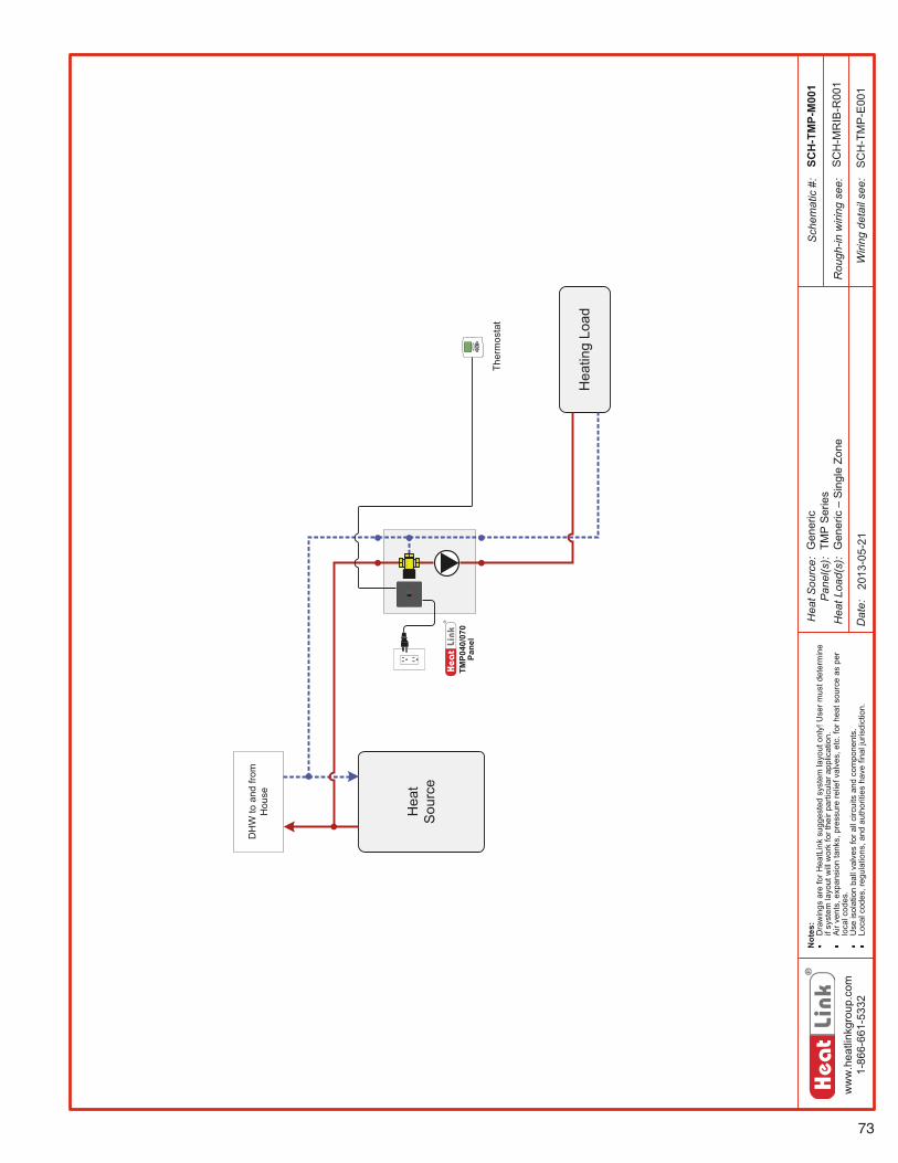
73
ww
w.h
eatli
nkgr
oup.
com
1-86
6-66
1-53
32
Hea
tSou
rce:
Pan
el(s
):H
eatL
oad(
s):
Sch
emat
ic#:
Dat
e:
Not
es:
Dra
win
gsar
efo
rHea
tLin
ksu
gges
ted
syst
emla
yout
only
!Use
rmus
tdet
erm
ine
ifsy
stem
layo
utw
illw
ork
fort
heir
parti
cula
rapp
licat
ion.
Air
vent
s,ex
pans
ion
tank
s,pr
essu
rere
liefv
alve
s,et
c.fo
rhea
tsou
rce
aspe
rlo
calc
odes
.U
seis
olat
ion
ball
valv
esfo
rall
circ
uits
and
com
pone
nts.
Loca
lcod
es,r
egul
atio
ns,a
ndau
thor
ities
have
final
juris
dict
ion.
Rou
gh-in
wiri
ngse
e:
Wiri
ngde
tail
see:
SCH
-TM
P-M
001
2013
-05-
21
SC
H-M
RIB
-R00
1
SC
H-T
MP
-E00
1
Gen
eric
TMP
Ser
ies
Gen
eric–
Sin
gle
Zone
Hea
ting
Load
TMP0
40/0
70Pa
nel
Hea
tS
ourc
e
DH
Wto
and
from
Hou
se
Ther
mos
tat
®
LinkHeat
74
www.heatlink.com
Mec
hani
cal R
oom
in a
Box
TMP 70 MBH 3-Way Mixing Panel with Zoning
Stk# TMP070Z
The TMP 3-Way Mixing Panel’s primary application is as a multizone mixing
device where there are no fl ow requirements in the primary loop. Intended to
be used with DHW tanks as a heat source, the pump is activated, and actuators
(sold separately) are opened once every 24 hours, for 15 minutes, to ensure that
potable water in the piping is not stagnant. The power box has thermostat inputs
and actuator outputs for up to four zones (two actuators per zone). At this time, a
DHW priority option for this panel is not available.
When the panel receives a call for heat, the pump is activated, and the
thermostatic control head in the 3-way mixing valve will automatically regulate
the water temperature in the secondary circuit. When used with a DHW tank as
a heat source, secondary zoning downstream of the panel is possible (subject to
local codes).
TMP – 3-Way Mixing Panel with Zoning
TMP070Z
Listing cETLus
Conforms to CAN/CSA-C22 No.14, UL508
Dimensions 14-3⁄4"H × 12-1⁄2"W × 6-1⁄2"D
Weight 17 lbs.
Nominal panel output 70,000 Btu/hr
Nominal fl ow 7.0 US gpm @ 20°F ΔT
Nominal pressure drop outside of panel 4 ft
Max ambient temperature 120°F
Max water temperature 200°F
Min required fl ow for correct temp control 1 US gpm
Power supply: pre-wired on system controller 110 V(ac); max. current 2A
Pump Non-ferrous, Grundfos UPS15-58
Auxiliary terminal 1 dry contact, max. load 1.5A
Temperature control method 1" 3-Way thermostatic
Temperature control range 110-140°F
Mix Valve Cv 3.7
Piping 3⁄4" 304 SS tubing
Piping connections 1" FNPT
Backplate 16 gauge galvanized steel
Enclosure Powder coated steel
Panel Components
Pump
3-Way Thermostatic Mixing Valve
Power Box with 6' Power Cord
• 24hr Timer for Potable Applications
• Auxiliary Dry Contacts for Heat Source
• Thermostat Inputs and Actuator Outputs for 4 Zones
• Bypass Function
24Vac Plug-in Transformer
Thermometer
Panel Enclosure (not shown)
1
2
3
4
5
1
5
3
2
4
Primary Supply
Secondary Supply
Primary Return
Secondary Return
* Lead time may vary. Call to confi rm time line.
USA - July 1, 2014
Stk# Description Pkg Qty Carton Qty Unit List Price / Unit
Special Order* TMP070Z TMP 70MBH 3-way Mixing Panel with Zoning 1 ea.
75
ww
w.h
eatli
nkgr
oup.
com
1-86
6-66
1-53
32
Hea
t Sou
rce:
Pan
el(s
):H
eat L
oad(
s):
Sch
emat
ic #
:
Dat
e:
Not
es:
Dra
win
gs a
re fo
r Hea
tLin
k su
gges
ted
syst
em la
yout
onl
y! U
ser m
ust d
eter
min
e if
syst
em la
yout
will
wor
k fo
r the
ir pa
rticu
lar a
pplic
atio
n.A
ir ve
nts,
exp
ansi
on ta
nks,
pre
ssur
e re
lief v
alve
s, e
tc. f
or h
eat s
ourc
e as
per
lo
cal c
odes
.U
se is
olat
ion
ball
valv
es fo
r all
circ
uits
and
com
pone
nts.
Loca
l cod
es, r
egul
atio
ns, a
nd a
utho
ritie
s ha
ve fi
nal j
uris
dict
ion.
Rou
gh-in
wiri
ng s
ee:
Wiri
ng d
etai
l see
:
TMP0
70Z
Pane
l
SCH
-TM
PZ-M
001
2013
-05-
23
SC
H-M
RIB
-R00
6
SC
H-T
MP
Z-E
001
Gen
eric
TMP
070Z
Gen
eric
–U
p to
4 Z
ones
Hea
tSo
urce
DH
W to
and
from
H
ouse
Hea
ting
Load
Up
to 4
Zon
es
®
LinkHeat
76
www.heatlink.com
Mec
hani
cal R
oom
in a
Box
TMP 85 MBH Dual Pump Mixing Panel
Stk# TMP085DP
The TMP 3-Way Mixing Panel’s primary application is as a single zone mixing
device where there are no fl ow requirements in the primary loop. Intended to be
used with DHW tanks as a heat source, the pump is activated once every 24 hours,
for 15 minutes, to ensure that potable water in the piping is not stagnant. At this
time, a DHW priority option for this panel is not available.
These panels can also be used as subpanels to provide additional mixed
temperature loops.
When the panel receives a call for heat, the pump is activated, and the
thermostatic control head in the 3-way mixing valve will automatically regulate
the water temperature in the secondary circuit. When not used with a DHW tank
as a heat source, secondary zoning downstream of the panel is possible. The
TMP085DP not only allows for higher output, but it is also a 2-zone panel. So
even with a DHW heat source, you can now have two radiant fl oor zones.
TMP – Dual Pump 3-Way Mixing Panel
TMP085DP
Listing cETLus
Conforms to CAN/CSA-C22 No.14, UL508
Dimensions 18-1⁄4"H × 16-1⁄4"W × 7-3⁄4"D
Weight 30 lbs.
Nominal panel output 85,000 Btu/hr
Nominal fl ow 2× 4.25 US gpm @ 20°F ΔT
Nominal pressure drop outside of panel 4 ft
Max ambient temperature 120°F
Max water temperature 200°F
Min required fl ow for correct temp control 1 US gpm
Power supply: pre-wired on system controller 110 V(ac); max. current 2A
Zone 1 pump Non-ferrous, Grundfos UPS15-58
Zone 2 pump Non-ferrous, Grundfos UPS15-58
Auxiliary terminal 1 dry contact, max. load 1.5A
Temperature control method 1" 3-Way thermostatic
Temperature control range 110-140°F
Mix Valve Cv 3.0
Piping 3⁄4" 304 SS tubing
Piping connections 1" FNPT primary, 3⁄4" FNPT secondary
Backplate 16 gauge galvanized steel
Enclosure Powder coated steel
Primary Return
Zone 1 Return
Zone 2 Return
Primary Supply
Zone 2 Supply
Zone 1 Supply
Panel Components
Zone 1 Pump with Check Valve
Zone 2 Pump with Check Valve
3-Way Thermostatic Mixing Valve
Power Box with 6' Power Cord
• 24hr Timer for Potable Applications
• Bypass Function
• Auxiliary Dry Contacts for Heat Source
Thermometer
Panel Enclosure (not shown)
1
1 2
3
4
5
2
3
4
5
USA - July 1, 2014
Stk# Description Pkg Qty Carton Qty Unit List Price / Unit
TMP085DP TMP 85MBH Dual Pump 3-way Mixing panel 1 ea.
77
ww
w.h
eatli
nkgr
oup.
com
1-86
6-66
1-53
32
Hea
t Sou
rce:
Pan
el(s
):H
eat L
oad(
s):
Sch
emat
ic #
:
Dat
e:
Not
es:
Dra
win
gs a
re fo
r Hea
tLin
k su
gges
ted
syst
em la
yout
onl
y! U
ser m
ust d
eter
min
e if
syst
em la
yout
will
wor
k fo
r the
ir pa
rticu
lar a
pplic
atio
n.A
ir ve
nts,
exp
ansi
on ta
nks,
pre
ssur
e re
lief v
alve
s, e
tc. f
or h
eat s
ourc
e as
per
lo
cal c
odes
.U
se is
olat
ion
ball
valv
es fo
r all
circ
uits
and
com
pone
nts.
Loca
l cod
es, r
egul
atio
ns, a
nd a
utho
ritie
s ha
ve fi
nal j
uris
dict
ion.
Rou
gh-in
wiri
ng s
ee:
Wiri
ng d
etai
l see
:
SCH
-TM
PDP-
M00
1
2013
-05-
21
SC
H-M
RIB
-R00
1
SC
H-T
MP
D-E
001
Gen
eric
TMP
085D
PG
ener
ic –
Dua
lZon
esHea
ting
Zone
1
Hea
tSo
urce
DH
W to
and
from
H
ouse
TMP0
85D
P Pa
nel
Che
ck V
alve
in
Bot
h Pu
mps
Hea
ting
Zone
2Zo
ne 2
The
rmos
tat
Zone
1 T
herm
osta
t
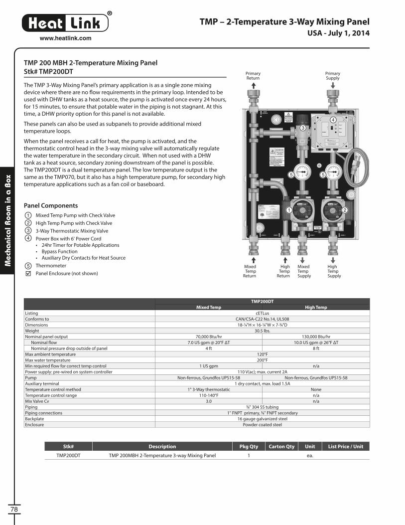
®
LinkHeat
78
www.heatlink.com
Mec
hani
cal R
oom
in a
Box
TMP 200 MBH 2-Temperature Mixing Panel
Stk# TMP200DT
The TMP 3-Way Mixing Panel’s primary application is as a single zone mixing
device where there are no fl ow requirements in the primary loop. Intended to be
used with DHW tanks as a heat source, the pump is activated once every 24 hours,
for 15 minutes, to ensure that potable water in the piping is not stagnant. At this
time, a DHW priority option for this panel is not available.
These panels can also be used as subpanels to provide additional mixed
temperature loops.
When the panel receives a call for heat, the pump is activated, and the
thermostatic control head in the 3-way mixing valve will automatically regulate
the water temperature in the secondary circuit. When not used with a DHW
tank as a heat source, secondary zoning downstream of the panel is possible.
The TMP200DT is a dual temperature panel. The low temperature output is the
same as the TMP070, but it also has a high temperature pump, for secondary high
temperature applications such as a fan coil or baseboard.
TMP – 2-Temperature 3-Way Mixing Panel
TMP200DT
Mixed Temp High Temp
Listing cETLus
Conforms to CAN/CSA-C22 No.14, UL508
Dimensions 18-1⁄4"H × 16-1⁄4"W × 7-3⁄4"D
Weight 30.5 lbs.
Nominal panel output 70,000 Btu/hr 130,000 Btu/hr
Nominal fl ow 7.0 US gpm @ 20°F ΔT 10.0 US gpm @ 26°F ΔT
Nominal pressure drop outside of panel 4 ft 8 ft
Max ambient temperature 120°F
Max water temperature 200°F
Min required fl ow for correct temp control 1 US gpm n/a
Power supply: pre-wired on system controller 110 V(ac); max. current 2A
Pump Non-ferrous, Grundfos UPS15-58 Non-ferrous, Grundfos UPS15-58
Auxiliary terminal 1 dry contact, max. load 1.5A
Temperature control method 1" 3-Way thermostatic None
Temperature control range 110-140°F n/a
Mix Valve Cv 3.0 n/a
Piping 3⁄4" 304 SS tubing
Piping connections 1" FNPT primary, 3⁄4" FNPT secondary
Backplate 16 gauge galvanized steel
Enclosure Powder coated steel
Panel Components
Mixed Temp Pump with Check Valve
High Temp Pump with Check Valve
3-Way Thermostatic Mixing Valve
Power Box with 6' Power Cord
• 24hr Timer for Potable Applications
• Bypass Function
• Auxiliary Dry Contacts for Heat Source
Thermometer
Panel Enclosure (not shown)
1
2
3
4
5
Primary Return
High Temp
Return
Mixed Temp
Return
Primary Supply
High Temp Supply
Mixed Temp Supply
1 2
3
4
5 5
USA - July 1, 2014
Stk# Description Pkg Qty Carton Qty Unit List Price / Unit
TMP200DT TMP 200MBH 2-Temperature 3-way Mixing Panel 1 ea.

79
ww
w.h
eatli
nkgr
oup.
com
1-86
6-66
1-53
32
Hea
t Sou
rce:
Pan
el(s
):H
eat L
oad(
s):
Sch
emat
ic #
:
Dat
e:
Not
es:
Dra
win
gs a
re fo
r Hea
tLin
k su
gges
ted
syst
em la
yout
onl
y! U
ser m
ust d
eter
min
e if
syst
em la
yout
will
wor
k fo
r the
ir pa
rticu
lar a
pplic
atio
n.A
ir ve
nts,
exp
ansi
on ta
nks,
pre
ssur
e re
lief v
alve
s, e
tc. f
or h
eat s
ourc
e as
per
lo
cal c
odes
.U
se is
olat
ion
ball
valv
es fo
r all
circ
uits
and
com
pone
nts.
Loca
l cod
es, r
egul
atio
ns, a
nd a
utho
ritie
s ha
ve fi
nal j
uris
dict
ion.
Rou
gh-in
wiri
ng s
ee:
Wiri
ng d
etai
l see
:
TMP2
00D
T Pa
nel
Che
ck V
alve
in
Bot
h P
umps
SCH
-TM
PDT-
M00
1
2013
-05-
22
SC
H-M
RIB
-R00
1
SC
H-T
MP
D-E
001
Gen
eric
TMP
200D
TG
ener
ic –
Dua
lZon
esHea
ting
Zone
1
Hea
tSo
urce
DH
W to
and
from
H
ouse
Zone
2 T
herm
osta
tH
eatin
g Zo
ne2
Zone
1 T
herm
osta
t
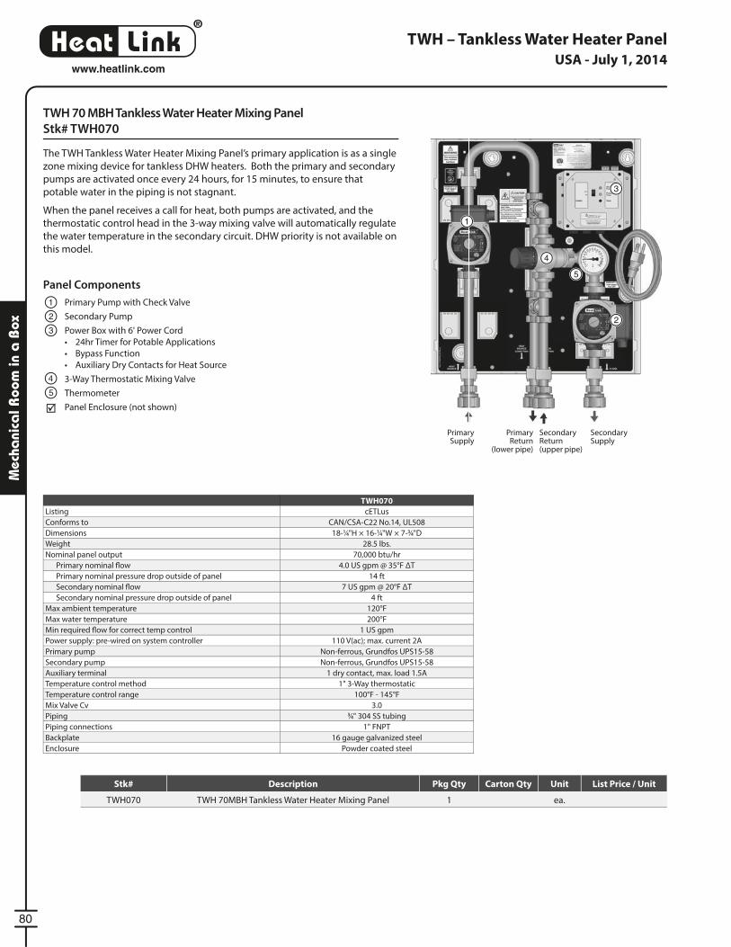
®
LinkHeat
80
www.heatlink.com
Mec
hani
cal R
oom
in a
Box
TWH 70 MBH Tankless Water Heater Mixing Panel
Stk# TWH070
The TWH Tankless Water Heater Mixing Panel’s primary application is as a single
zone mixing device for tankless DHW heaters. Both the primary and secondary
pumps are activated once every 24 hours, for 15 minutes, to ensure that
potable water in the piping is not stagnant.
When the panel receives a call for heat, both pumps are activated, and the
thermostatic control head in the 3-way mixing valve will automatically regulate
the water temperature in the secondary circuit. DHW priority is not available on
this model.
TWH – Tankless Water Heater Panel
TWH070
Listing cETLus
Conforms to CAN/CSA-C22 No.14, UL508
Dimensions 18-1⁄4"H × 16-1⁄4"W × 7-3⁄4"D
Weight 28.5 lbs.
Nominal panel output 70,000 btu/hr
Primary nominal fl ow 4.0 US gpm @ 35°F ΔT
Primary nominal pressure drop outside of panel 14 ft
Secondary nominal fl ow 7 US gpm @ 20°F ΔT
Secondary nominal pressure drop outside of panel 4 ft
Max ambient temperature 120°F
Max water temperature 200°F
Min required fl ow for correct temp control 1 US gpm
Power supply: pre-wired on system controller 110 V(ac); max. current 2A
Primary pump Non-ferrous, Grundfos UPS15-58
Secondary pump Non-ferrous, Grundfos UPS15-58
Auxiliary terminal 1 dry contact, max. load 1.5A
Temperature control method 1" 3-Way thermostatic
Temperature control range 100°F - 145°F
Mix Valve Cv 3.0
Piping 3⁄4" 304 SS tubing
Piping connections 1" FNPT
Backplate 16 gauge galvanized steel
Enclosure Powder coated steel
Panel Components
Primary Pump with Check Valve
Secondary Pump
Power Box with 6' Power Cord
• 24hr Timer for Potable Applications
• Bypass Function
• Auxiliary Dry Contacts for Heat Source
3-Way Thermostatic Mixing Valve
Thermometer
Panel Enclosure (not shown)
1
2
3
4
5
Primary Supply
Secondary Supply
Primary Return
(lower pipe)
Secondary Return(upper pipe)
1
2
3
4
5
USA - July 1, 2014
Stk# Description Pkg Qty Carton Qty Unit List Price / Unit
TWH070 TWH 70MBH Tankless Water Heater Mixing Panel 1 ea.

81
ww
w.h
eatli
nk.c
om1-
866-
661-
5332
Hea
tSou
rce:
Pan
el(s
):H
eatL
oad(
s):
Sch
emat
ic#:
Dat
e:
Not
es:
Dra
win
gsar
efo
rHea
tLin
ksu
gges
ted
syst
emla
yout
only
!Use
rmus
tdet
erm
ine
ifsy
stem
layo
utw
illw
ork
fort
heir
parti
cula
rapp
licat
ion.
Air
vent
s,ex
pans
ion
tank
s,pr
essu
rere
liefv
alve
s,et
c.fo
rhea
tsou
rce
aspe
rlo
calc
odes
.U
seis
olat
ion
ball
valv
esfo
rall
circ
uits
and
com
pone
nts.
Loca
lcod
es,r
egul
atio
ns,a
ndau
thor
ities
have
final
juris
dict
ion.
Rou
gh-in
wiri
ngse
e:
Wiri
ngde
tail
see:
TWH
070
Pane
l
Che
ckV
alve
inP
rimar
yP
ump
2013
-03-
18
SC
H-M
RIB
-R00
1
SC
H-T
WH
-E00
1
Gen
eric
TWH
070
Gen
eric–
Sin
gle
Zone
DH
WS
uppl
yto
Hou
se
Ther
mos
tat
Hea
tS
ourc
e
Hea
ting
Load
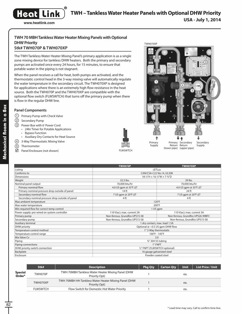
®
LinkHeat
82
www.heatlink.com
Mec
hani
cal R
oom
in a
Box
TWH – Tankless Water Heater Panels with Optional DHW Priority
TWH 70 MBH Tankless Water Heater Mixing Panels with Optional
DHW Priority
Stk# TWH070P & TWH070XP
The TWH Tankless Water Heater Mixing Panel’s primary application is as a single
zone mixing device for tankless DHW heaters. Both the primary and secondary
pumps are activated once every 24 hours, for 15 minutes, to ensure that
potable water in the piping is not stagnant.
When the panel receives a call for heat, both pumps are activated, and the
thermostatic control head in the 3-way mixing valve will automatically regulate
the water temperature in the secondary circuit. The TWH070XP is designed
for applications where there is an extremely high fl ow resistance in the heat
source. Both the TWH070P and the TWH070XP are compatible with the
optional fl ow switch (FLWSWTCH) that turns off the primary pump when there
is fl ow in the regular DHW line.
TWH070XP
TWH070P TWH070XP
Listing cETLus
Conforms to CAN/CSA-C22 No.14, UL508
Dimensions 18-1⁄4"H × 16-1⁄4"W × 7-3⁄4"D
Weight 32.5 lbs. 39 lbs.
Nominal panel output 70,000 btu/hr 70,000 btu/hr
Primary nominal fl ow 4.0 US gpm @ 35°F ΔT 4.0 US gpm @ 35°F ΔT
Primary nominal pressure drop outside of panel 14 ft 24 ft
Secondary nominal fl ow 7 US gpm @ 20°F ΔT 7 US gpm @ 20°F ΔT
Secondary nominal pressure drop outside of panel 4 ft 4 ft
Max ambient temperature 120°F
Max water temperature 200°F
Min required fl ow for correct temp control 1 US gpm
Power supply: pre-wired on system controller 110 V(ac); max. current 2A 110 V(ac); max. current 3A
Primary pump Non-ferrous, Grundfos UPS15-58 Non-ferrous, Grundfos UPS26-99BFC
Secondary pump Non-ferrous, Grundfos UPS15-58 Non-ferrous, Grundfos UPS15-58
Auxiliary terminal 1 dry contact, max. load 1.5A
DHW priority Optional @ ~0.5 US gpm DHW fl ow
Temperature control method 1" 3-Way thermostatic
Temperature control range 100°F - 145°F
Mix Valve Cv 3.0
Piping 3⁄4" 304 SS tubing
Piping connections 1" FNPT
DHW priority switch connection 1⁄2" FNPT (FLWSWTCH optional)
Backplate 16 gauge galvanized steel
Enclosure Powder coated steel
Panel Components
Primary Pump with Check Valve
Secondary Pump
Power Box with 6' Power Cord
• 24hr Timer for Potable Applications
• Bypass Function
• Auxiliary Dry Contacts for Heat Source
3-Way Thermostatic Mixing Valve
Thermometer
Panel Enclosure (not shown)
1
2
3
4
5
1
2
3
4
5
FLWSWTCH
Primary Supply
Secondary Supply
Primary Return
(lower pipe)
Secondary Return(upper pipe)
* Lead time may vary. Call to confi rm time line.
USA - July 1, 2014
FLWSWTCH Flow Switch for Domestic Hot Water Priority 1 ea.
Stk# Description Pkg Qty Carton Qty Unit List Price / Unit
Special Order* TWH070P
TWH 70MBH Tankless Water Heater Mixing Panel (DHW
Priority Opt)1 ea.
TWH070XPTWH 70MBH HH Tankless Water Heater Mixing Panel (DHW
Priority Opt)1 ea.
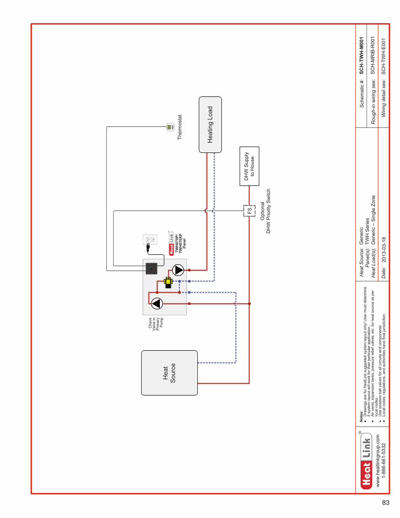
83
ww
w.h
eatli
nkgr
oup.
com
1-86
6-66
1-53
32
Hea
t Sou
rce:
Pan
el(s
):H
eat L
oad(
s):
Sch
emat
ic #
:
Dat
e:
Not
es:
Dra
win
gs a
re fo
r Hea
tLin
k su
gges
ted
syst
em la
yout
onl
y! U
ser m
ust d
eter
min
e if
syst
em la
yout
will
wor
k fo
r the
ir pa
rticu
lar a
pplic
atio
n.A
ir ve
nts,
exp
ansi
on ta
nks,
pre
ssur
e re
lief v
alve
s, e
tc. f
or h
eat s
ourc
e as
per
lo
cal c
odes
.U
se is
olat
ion
ball
valv
es fo
r all
circ
uits
and
com
pone
nts.
Loca
l cod
es, r
egul
atio
ns, a
nd a
utho
ritie
s ha
ve fi
nal j
uris
dict
ion.
Rou
gh-in
wiri
ng s
ee:
Wiri
ng d
etai
l see
:
TWH
070P
/TW
H07
0XP
Pane
l
Che
ck
Val
ve in
Pr
imar
y Pu
mp
SCH
-TW
H-M
001
2013
-03-
18
SC
H-M
RIB
-R00
1
SC
H-T
WH
-E00
1
Gen
eric
TWH
Ser
ies
Gen
eric
–S
ingl
e Zo
ne
DH
W S
uppl
y to
Hou
se
Ther
mos
tat
Hea
tS
ourc
e
Hea
ting
Load
Opt
iona
lD
HW
Prio
rity
Sw
itch
FS
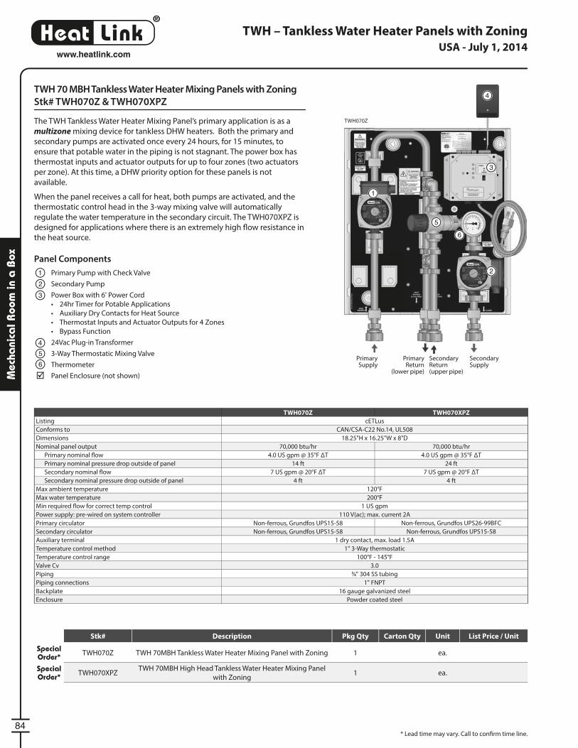
®
LinkHeat
84
www.heatlink.com
Mec
hani
cal R
oom
in a
Box
TWH – Tankless Water Heater Panels with Zoning
TWH 70 MBH Tankless Water Heater Mixing Panels with Zoning
Stk# TWH070Z & TWH070XPZ
The TWH Tankless Water Heater Mixing Panel’s primary application is as a
multizone mixing device for tankless DHW heaters. Both the primary and
secondary pumps are activated once every 24 hours, for 15 minutes, to
ensure that potable water in the piping is not stagnant. The power box has
thermostat inputs and actuator outputs for up to four zones (two actuators
per zone). At this time, a DHW priority option for these panels is not
available.
When the panel receives a call for heat, both pumps are activated, and the
thermostatic control head in the 3-way mixing valve will automatically
regulate the water temperature in the secondary circuit. The TWH070XPZ is
designed for applications where there is an extremely high fl ow resistance in
the heat source.
TWH070ZTWH070Z
* Lead time may vary. Call to confi rm time line.
Panel Components
Primary Pump with Check Valve
Secondary Pump
Power Box with 6' Power Cord
• 24hr Timer for Potable Applications
• Auxiliary Dry Contacts for Heat Source
• Thermostat Inputs and Actuator Outputs for 4 Zones
• Bypass Function
24Vac Plug-in Transformer
3-Way Thermostatic Mixing Valve
Thermometer
Panel Enclosure (not shown)
1
2
3
5
4
4
6
1
2
3
5
6
TWH070Z TWH070XPZ
Listing cETLus
Conforms to CAN/CSA-C22 No.14, UL508
Dimensions 18.25"H x 16.25"W x 8"D
Nominal panel output 70,000 btu/hr 70,000 btu/hr
Primary nominal fl ow 4.0 US gpm @ 35°F ΔT 4.0 US gpm @ 35°F ΔT
Primary nominal pressure drop outside of panel 14 ft 24 ft
Secondary nominal fl ow 7 US gpm @ 20°F ΔT 7 US gpm @ 20°F ΔT
Secondary nominal pressure drop outside of panel 4 ft 4 ft
Max ambient temperature 120°F
Max water temperature 200°F
Min required fl ow for correct temp control 1 US gpm
Power supply: pre-wired on system controller 110 V(ac); max. current 2A
Primary circulator Non-ferrous, Grundfos UPS15-58 Non-ferrous, Grundfos UPS26-99BFC
Secondary circulator Non-ferrous, Grundfos UPS15-58 Non-ferrous, Grundfos UPS15-58
Auxiliary terminal 1 dry contact, max. load 1.5A
Temperature control method 1" 3-Way thermostatic
Temperature control range 100°F - 145°F
Valve Cv 3.0
Piping 3⁄4" 304 SS tubing
Piping connections 1" FNPT
Backplate 16 gauge galvanized steel
Enclosure Powder coated steel
Primary Supply
Secondary Supply
Primary Return
(lower pipe)
Secondary Return(upper pipe)
USA - July 1, 2014
Stk# Description Pkg Qty Carton Qty Unit List Price / Unit
Special Order* TWH070Z TWH 70MBH Tankless Water Heater Mixing Panel with Zoning 1 ea.
Special Order* TWH070XPZ
TWH 70MBH High Head Tankless Water Heater Mixing Panel
with Zoning1 ea.
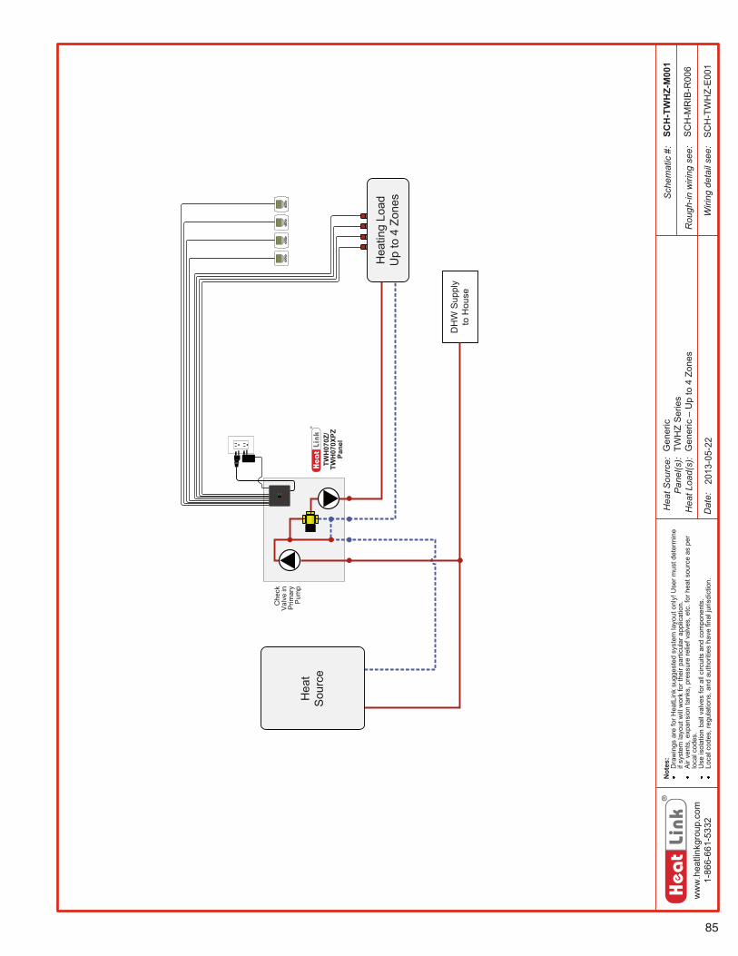
85
ww
w.h
eatli
nkgr
oup.
com
1-86
6-66
1-53
32
Hea
t Sou
rce:
Pan
el(s
):H
eat L
oad(
s):
Sch
emat
ic #
:
Dat
e:
Not
es:
Dra
win
gs a
re fo
r Hea
tLin
k su
gges
ted
syst
em la
yout
onl
y! U
ser m
ust d
eter
min
e if
syst
em la
yout
will
wor
k fo
r the
ir pa
rticu
lar a
pplic
atio
n.A
ir ve
nts,
exp
ansi
on ta
nks,
pre
ssur
e re
lief v
alve
s, e
tc. f
or h
eat s
ourc
e as
per
lo
cal c
odes
.U
se is
olat
ion
ball
valv
es fo
r all
circ
uits
and
com
pone
nts.
Loca
l cod
es, r
egul
atio
ns, a
nd a
utho
ritie
s ha
ve fi
nal j
uris
dict
ion.
Rou
gh-in
wiri
ng s
ee:
Wiri
ng d
etai
l see
:
TWH
070Z
/TW
H07
0XPZ
Pa
nel
Che
ck
Val
ve in
Pr
imar
y Pu
mp
SCH
-TW
HZ-
M00
1
2013
-05-
22
SC
H-M
RIB
-R00
6
SC
H-T
WH
Z-E
001
Gen
eric
TWH
Z S
erie
sG
ener
ic –
Up
to 4
Zon
es
DH
W S
uppl
y to
Hou
se
Hea
tS
ourc
e
Hea
ting
Load
Up
to 4
Zon
es
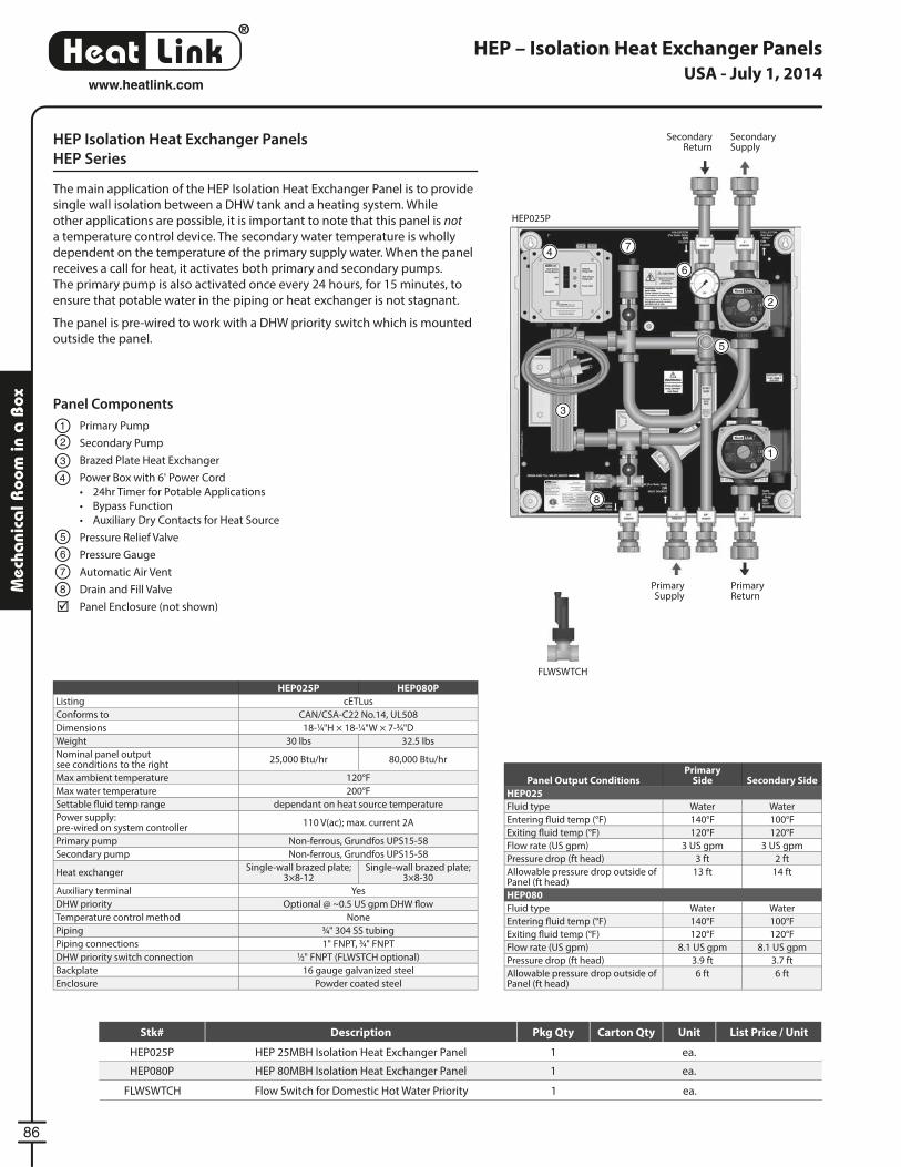
®
LinkHeat
86
www.heatlink.com
Mec
hani
cal R
oom
in a
Box
HEP – Isolation Heat Exchanger Panels
HEP Isolation Heat Exchanger Panels
HEP Series
The main application of the HEP Isolation Heat Exchanger Panel is to provide
single wall isolation between a DHW tank and a heating system. While
other applications are possible, it is important to note that this panel is not
a temperature control device. The secondary water temperature is wholly
dependent on the temperature of the primary supply water. When the panel
receives a call for heat, it activates both primary and secondary pumps.
The primary pump is also activated once every 24 hours, for 15 minutes, to
ensure that potable water in the piping or heat exchanger is not stagnant.
The panel is pre-wired to work with a DHW priority switch which is mounted
outside the panel.
HEP025P
FLWSWTCH
HEP025P HEP080P
Listing cETLus
Conforms to CAN/CSA-C22 No.14, UL508
Dimensions 18-1⁄4"H × 18-1⁄4"W × 7-3⁄4"D
Weight 30 lbs 32.5 lbs
Nominal panel outputsee conditions to the right
25,000 Btu/hr 80,000 Btu/hr
Max ambient temperature 120°F
Max water temperature 200°F
Settable fl uid temp range dependant on heat source temperature
Power supply:pre-wired on system controller
110 V(ac); max. current 2A
Primary pump Non-ferrous, Grundfos UPS15-58
Secondary pump Non-ferrous, Grundfos UPS15-58
Heat exchangerSingle-wall brazed plate;
3×8-12Single-wall brazed plate;
3×8-30
Auxiliary terminal Yes
DHW priority Optional @ ~0.5 US gpm DHW fl ow
Temperature control method None
Piping 3⁄4" 304 SS tubing
Piping connections 1" FNPT, 3⁄4" FNPT
DHW priority switch connection 1⁄2" FNPT (FLWSTCH optional)
Backplate 16 gauge galvanized steel
Enclosure Powder coated steel
Panel Components
Primary Pump
Secondary Pump
Brazed Plate Heat Exchanger
Power Box with 6' Power Cord
• 24hr Timer for Potable Applications
• Bypass Function
• Auxiliary Dry Contacts for Heat Source
Pressure Relief Valve
Pressure Gauge
Automatic Air Vent
Drain and Fill Valve
Panel Enclosure (not shown)
1
12
2
3
3
4
4
5
5
6
6
7
7
8
8
Primary Supply
Primary Return
Panel Output ConditionsPrimary
Side Secondary Side
HEP025
Fluid type Water Water
Entering fl uid temp (°F) 140°F 100°F
Exiting fl uid temp (°F) 120°F 120°F
Flow rate (US gpm) 3 US gpm 3 US gpm
Pressure drop (ft head) 3 ft 2 ft
Allowable pressure drop outside of Panel (ft head)
13 ft 14 ft
HEP080
Fluid type Water Water
Entering fl uid temp (°F) 140°F 100°F
Exiting fl uid temp (°F) 120°F 120°F
Flow rate (US gpm) 8.1 US gpm 8.1 US gpm
Pressure drop (ft head) 3.9 ft 3.7 ft
Allowable pressure drop outside of Panel (ft head)
6 ft 6 ft
Secondary Return
Secondary Supply
USA - July 1, 2014
FLWSWTCH Flow Switch for Domestic Hot Water Priority 1 ea.
Stk# Description Pkg Qty Carton Qty Unit List Price / Unit
HEP025P HEP 25MBH Isolation Heat Exchanger Panel 1 ea.
HEP080P HEP 80MBH Isolation Heat Exchanger Panel 1 ea.
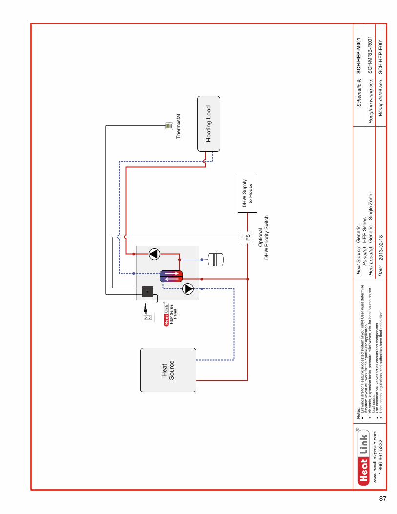
87
ww
w.h
eatli
nkgr
oup.
com
1-86
6-66
1-53
32
Hea
t Sou
rce:
Pan
el(s
):H
eat L
oad(
s):
Sch
emat
ic #
:
Dat
e:
Not
es:
Dra
win
gs a
re fo
r Hea
tLin
k su
gges
ted
syst
em la
yout
onl
y! U
ser m
ust d
eter
min
e if
syst
em la
yout
will
wor
k fo
r the
ir pa
rticu
lar a
pplic
atio
n.A
ir ve
nts,
exp
ansi
on ta
nks,
pre
ssur
e re
lief v
alve
s, e
tc. f
or h
eat s
ourc
e as
per
lo
cal c
odes
.U
se is
olat
ion
ball
valv
es fo
r all
circ
uits
and
com
pone
nts.
Loca
l cod
es, r
egul
atio
ns, a
nd a
utho
ritie
s ha
ve fi
nal j
uris
dict
ion.
Rou
gh-in
wiri
ng s
ee:
Wiri
ng d
etai
l see
:
HEP
Ser
ies
Pane
l
DH
W S
uppl
y to
Hou
se
Ther
mos
tat
Hea
tS
ourc
e
Hea
ting
Load
SCH
-HEP
-M00
1
2013
-02-
18
SC
H-M
RIB
-R00
1
SC
H-H
EP
-E00
1
Opt
iona
l D
HW
Prio
rity
Sw
itch
FS Gen
eric
HE
P S
erie
sG
ener
ic –
Sin
gle
Zone
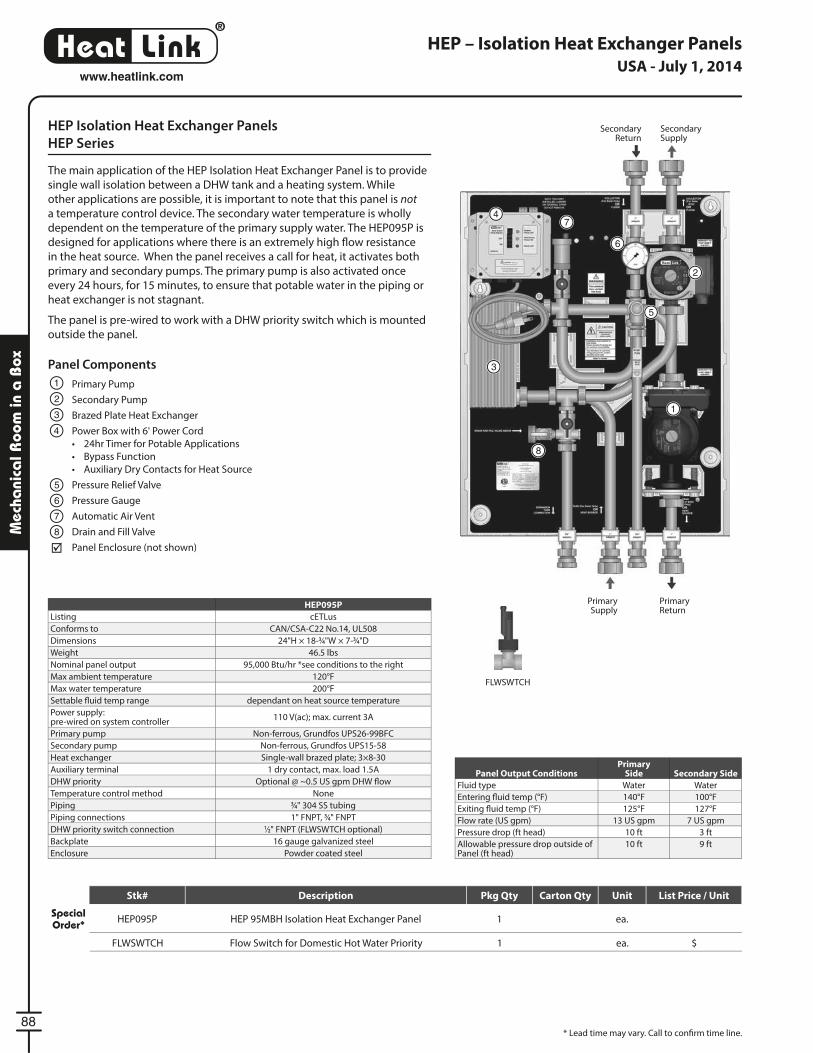
®
LinkHeat
88
www.heatlink.com
Mec
hani
cal R
oom
in a
Box
HEP095P
Listing cETLus
Conforms to CAN/CSA-C22 No.14, UL508
Dimensions 24"H × 18-3⁄4"W × 7-3⁄4"D
Weight 46.5 lbs
Nominal panel output 95,000 Btu/hr *see conditions to the right
Max ambient temperature 120°F
Max water temperature 200°F
Settable fl uid temp range dependant on heat source temperature
Power supply:pre-wired on system controller
110 V(ac); max. current 3A
Primary pump Non-ferrous, Grundfos UPS26-99BFC
Secondary pump Non-ferrous, Grundfos UPS15-58
Heat exchanger Single-wall brazed plate; 3×8-30
Auxiliary terminal 1 dry contact, max. load 1.5A
DHW priority Optional @ ~0.5 US gpm DHW fl ow
Temperature control method None
Piping 3⁄4" 304 SS tubing
Piping connections 1" FNPT, 3⁄4" FNPT
DHW priority switch connection 1⁄2" FNPT (FLWSWTCH optional)
Backplate 16 gauge galvanized steel
Enclosure Powder coated steel
Panel Output ConditionsPrimary
Side Secondary Side
Fluid type Water Water
Entering fl uid temp (°F) 140°F 100°F
Exiting fl uid temp (°F) 125°F 127°F
Flow rate (US gpm) 13 US gpm 7 US gpm
Pressure drop (ft head) 10 ft 3 ft
Allowable pressure drop outside of Panel (ft head)
10 ft 9 ft
HEP – Isolation Heat Exchanger Panels
HEP Isolation Heat Exchanger Panels
HEP Series
The main application of the HEP Isolation Heat Exchanger Panel is to provide
single wall isolation between a DHW tank and a heating system. While
other applications are possible, it is important to note that this panel is not
a temperature control device. The secondary water temperature is wholly
dependent on the temperature of the primary supply water. The HEP095P is
designed for applications where there is an extremely high fl ow resistance
in the heat source. When the panel receives a call for heat, it activates both
primary and secondary pumps. The primary pump is also activated once
every 24 hours, for 15 minutes, to ensure that potable water in the piping or
heat exchanger is not stagnant.
The panel is pre-wired to work with a DHW priority switch which is mounted
outside the panel.
Panel Components
Primary Pump
Secondary Pump
Brazed Plate Heat Exchanger
Power Box with 6' Power Cord
• 24hr Timer for Potable Applications
• Bypass Function
• Auxiliary Dry Contacts for Heat Source
Pressure Relief Valve
Pressure Gauge
Automatic Air Vent
Drain and Fill Valve
Panel Enclosure (not shown)
1
12
2
3
3
4
4
5
5
6
6
7
7
8
8
Primary Supply
Primary Return
Secondary Return
Secondary Supply
FLWSWTCH
* Lead time may vary. Call to confi rm time line.
USA - July 1, 2014
FLWSWTCH Flow Switch for Domestic Hot Water Priority 1 ea. $
Stk# Description Pkg Qty Carton Qty Unit List Price / Unit
Special Order* HEP095P HEP 95MBH Isolation Heat Exchanger Panel 1 ea.

89
ww
w.h
eatli
nkgr
oup.
com
1-86
6-66
1-53
32
Hea
t Sou
rce:
Pan
el(s
):H
eat L
oad(
s):
Sch
emat
ic #
:
Dat
e:
Not
es:
Dra
win
gs a
re fo
r Hea
tLin
k su
gges
ted
syst
em la
yout
onl
y! U
ser m
ust d
eter
min
e if
syst
em la
yout
will
wor
k fo
r the
ir pa
rticu
lar a
pplic
atio
n.A
ir ve
nts,
exp
ansi
on ta
nks,
pre
ssur
e re
lief v
alve
s, e
tc. f
or h
eat s
ourc
e as
per
lo
cal c
odes
.U
se is
olat
ion
ball
valv
es fo
r all
circ
uits
and
com
pone
nts.
Loca
l cod
es, r
egul
atio
ns, a
nd a
utho
ritie
s ha
ve fi
nal j
uris
dict
ion.
Rou
gh-in
wiri
ng s
ee:
Wiri
ng d
etai
l see
:
HEP
Ser
ies
Pane
l
DH
W S
uppl
y to
Hou
se
Ther
mos
tat
Hea
tS
ourc
e
Hea
ting
Load
SCH
-HEP
-M00
1
2013
-02-
18
SC
H-M
RIB
-R00
1
SC
H-H
EP
-E00
1
Opt
iona
l D
HW
Prio
rity
Sw
itch
FS Gen
eric
HE
P S
erie
sG
ener
ic –
Sin
gle
Zone
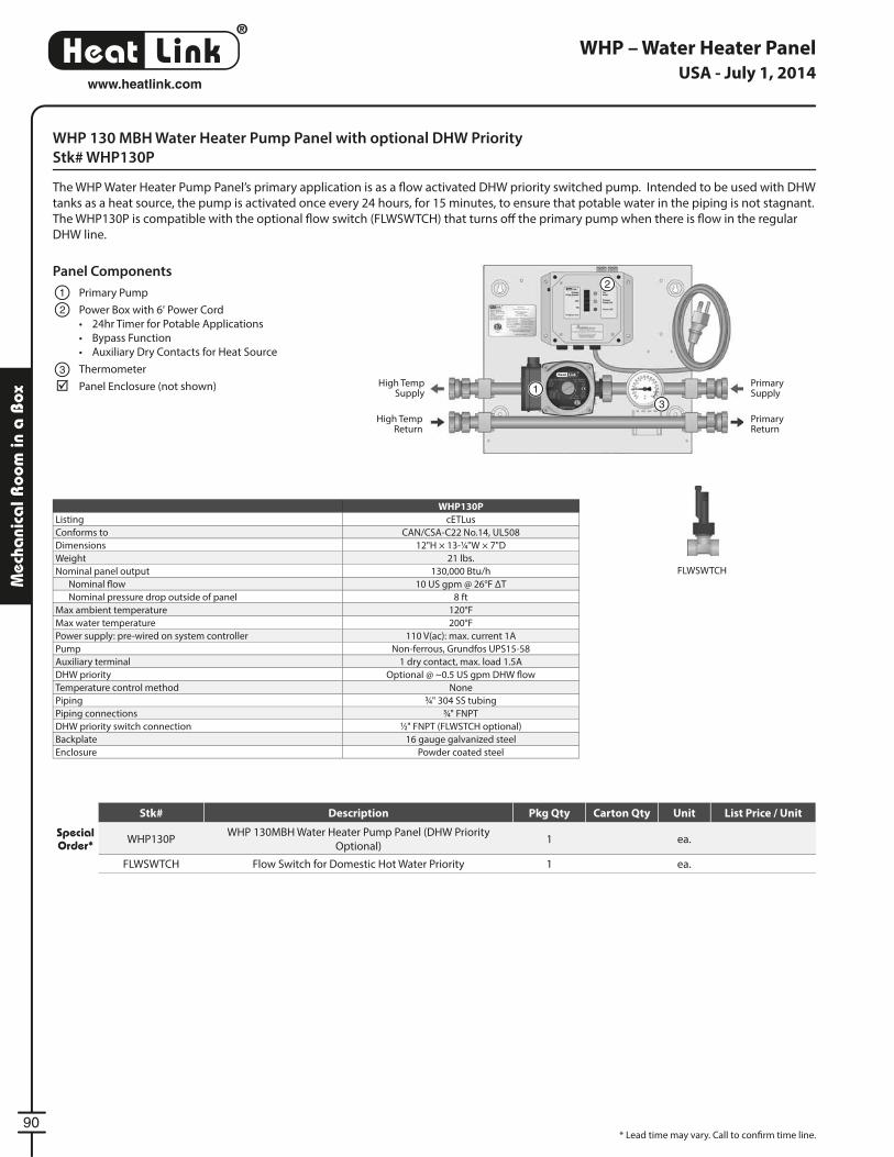
®
LinkHeat
90
www.heatlink.com
Mec
hani
cal R
oom
in a
Box
WHP – Water Heater Panel
WHP 130 MBH Water Heater Pump Panel with optional DHW Priority
Stk# WHP130P
The WHP Water Heater Pump Panel’s primary application is as a fl ow activated DHW priority switched pump. Intended to be used with DHW
tanks as a heat source, the pump is activated once every 24 hours, for 15 minutes, to ensure that potable water in the piping is not stagnant.
The WHP130P is compatible with the optional fl ow switch (FLWSWTCH) that turns off the primary pump when there is fl ow in the regular
DHW line.
WHP130P
Listing cETLus
Conforms to CAN/CSA-C22 No.14, UL508
Dimensions 12"H × 13-1⁄4"W × 7"D
Weight 21 lbs.
Nominal panel output 130,000 Btu/h
Nominal fl ow 10 US gpm @ 26°F ΔT
Nominal pressure drop outside of panel 8 ft
Max ambient temperature 120°F
Max water temperature 200°F
Power supply: pre-wired on system controller 110 V(ac): max. current 1A
Pump Non-ferrous, Grundfos UPS15-58
Auxiliary terminal 1 dry contact, max. load 1.5A
DHW priority Optional @ ~0.5 US gpm DHW fl ow
Temperature control method None
Piping 3⁄4" 304 SS tubing
Piping connections 3⁄4" FNPT
DHW priority switch connection 1⁄2" FNPT (FLWSTCH optional)
Backplate 16 gauge galvanized steel
Enclosure Powder coated steel
Panel Components
Primary Pump
Power Box with 6' Power Cord
• 24hr Timer for Potable Applications
• Bypass Function
• Auxiliary Dry Contacts for Heat Source
Thermometer
Panel Enclosure (not shown)
1
1
2
2
3
3Primary Return
High Temp Return
Primary Supply
High Temp Supply
FLWSWTCH
* Lead time may vary. Call to confi rm time line.
USA - July 1, 2014
Stk# Description Pkg Qty Carton Qty Unit List Price / Unit
Special Order* WHP130P
WHP 130MBH Water Heater Pump Panel (DHW Priority
Optional)1 ea.
FLWSWTCH Flow Switch for Domestic Hot Water Priority 1 ea.
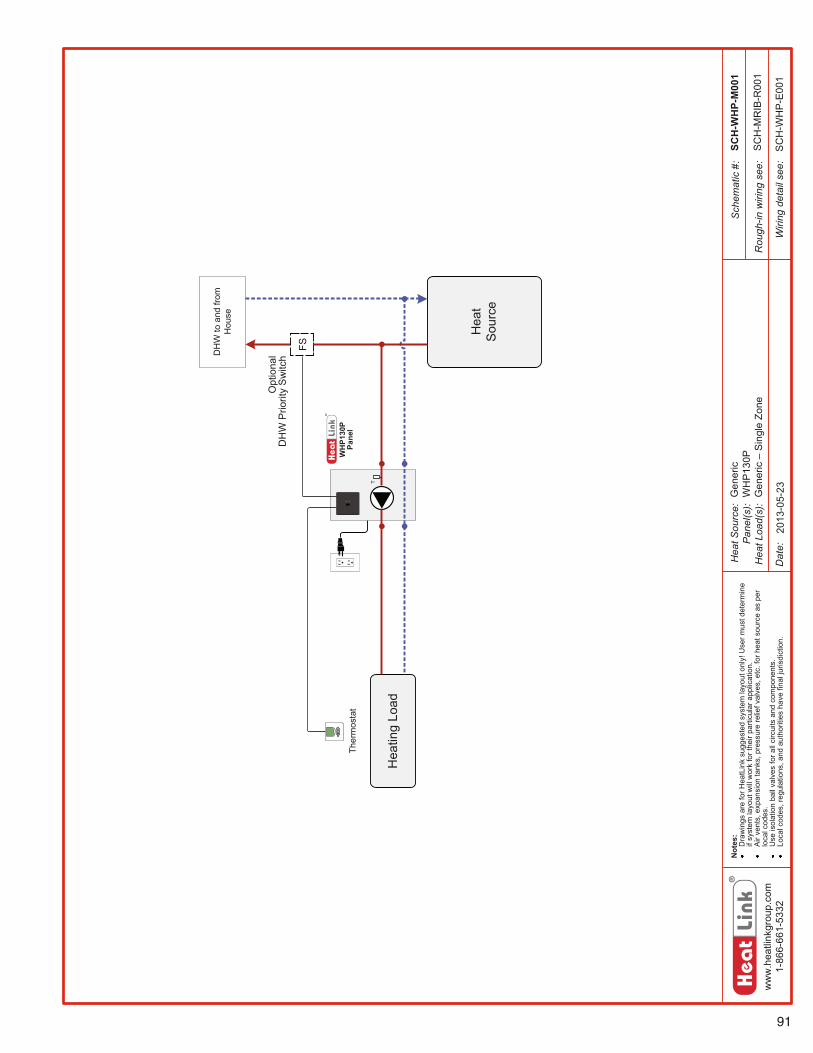
91
ww
w.h
eatli
nkgr
oup.
com
1-86
6-66
1-53
32
Hea
t Sou
rce:
Pan
el(s
):H
eat L
oad(
s):
Sch
emat
ic #
:
Dat
e:
Not
es:
Dra
win
gs a
re fo
r Hea
tLin
k su
gges
ted
syst
em la
yout
onl
y! U
ser m
ust d
eter
min
e if
syst
em la
yout
will
wor
k fo
r the
ir pa
rticu
lar a
pplic
atio
n.A
ir ve
nts,
exp
ansi
on ta
nks,
pre
ssur
e re
lief v
alve
s, e
tc. f
or h
eat s
ourc
e as
per
lo
cal c
odes
.U
se is
olat
ion
ball
valv
es fo
r all
circ
uits
and
com
pone
nts.
Loca
l cod
es, r
egul
atio
ns, a
nd a
utho
ritie
s ha
ve fi
nal j
uris
dict
ion.
Rou
gh-in
wiri
ng s
ee:
Wiri
ng d
etai
l see
:
WH
P130
P Pa
nel
T
SCH
-WH
P-M
001
2013
-05-
23
SC
H-M
RIB
-R00
1
SC
H-W
HP
-E00
1
Gen
eric
WH
P13
0PG
ener
ic –
Sin
gle
Zone
Hea
ting
Load
Hea
tSo
urce
DH
W to
and
from
H
ouse
Ther
mos
tat
Opt
iona
lD
HW
Prio
rity
Sw
itch
FS
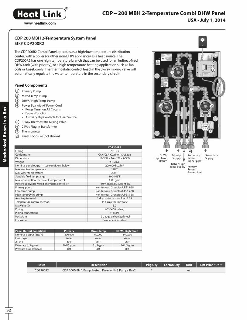
®
LinkHeat
92
www.heatlink.com
Mec
hani
cal R
oom
in a
Box
CDP 200 MBH 2-Temperature System Panel
Stk# CDP200R2
The CDP200R2 Combi Panel operates as a high/low temperature distribution
center, with a boiler (or other non-DHW appliance) as a heat source. The
CDP200R2 has one high temperature branch that can be used for an indirect-fi red
DHW tank (with priority), or a high temperature heating application such as fan
coils or baseboards. The thermostatic control head in the 3-way mixing valve will
automatically regulate the water temperature in the secondary circuit.
CDP – 200 MBH 2-Temperature Combi DHW Panel
CDP200R2
Listing cETLus
Conforms to CAN/CSA-C22 No.14, UL508
Dimensions 18-1⁄4"H × 16-1⁄4"W × 7-3⁄4"D
Weight 41.5 lbs.
Nominal panel output* - see conditions below 200,000 Btu/hr*
Max ambient temperature 120°F
Max water temperature 200°F
Settable fl uid temp range 100-145°F
Min required fl ow for correct temp control 1 US gpm
Power supply: pre-wired on system controller 110 V(ac); max. current 3A
Primary pump Non-ferrous, Grundfos UPS15-58
Low temp pump Non-ferrous, Grundfos UPS15-58
High temp/DHW pump Non-ferrous, Grundfos UPS15-58
Auxiliary terminal 2 dry contacts, max. load 1.5A
Temperature control method 1" 3-Way thermostatic
Mix Valve Cv 3.0
Piping 3⁄4" 304 SS tubing
Piping connections 1" FNPT
Backplate 16 gauge galvanized steel
Enclosure Powder coated steel
Panel Components
Primary Pump
Mixed Temp Pump
DHW / High Temp Pump
Power Box with 6' Power Cord
• Purge Timer on All Circuits
• Bypass Function
• Auxiliary Dry Contacts for Heat Source
3-Way Thermostatic Mixing Valve
24Vac Plug-in Transformer
Thermometer
Panel Enclosure (not shown)
1
1
2
2
3
3
5
5
4
4
6
6
7 7
DHW /High Temp
Return
Primary Supply
DHW / High Temp Supply
Secondary Supply
Panel Output Conditions Primary Mixed Temp DHW / High Temp
Nominal output (Btu/h) 200,000 60,000 140,000
Fluid type Water Water Water
ΔT (°F) 40°F 20°F 26°F
Flow rate (US gpm) 10 US gpm 6 US gpm 10 US gpm
Pressure drop (ft head) 8 ft 4 ft 8 ft
Secondary Return(upper pipe)
PrimaryReturn(lower pipe)
USA - July 1, 2014
Stk# Description Pkg Qty Carton Qty Unit List Price / Unit
CDP200R2 CDP 200MBH 2-Temp System Panel with 3 Pumps Rev2 1 ea.
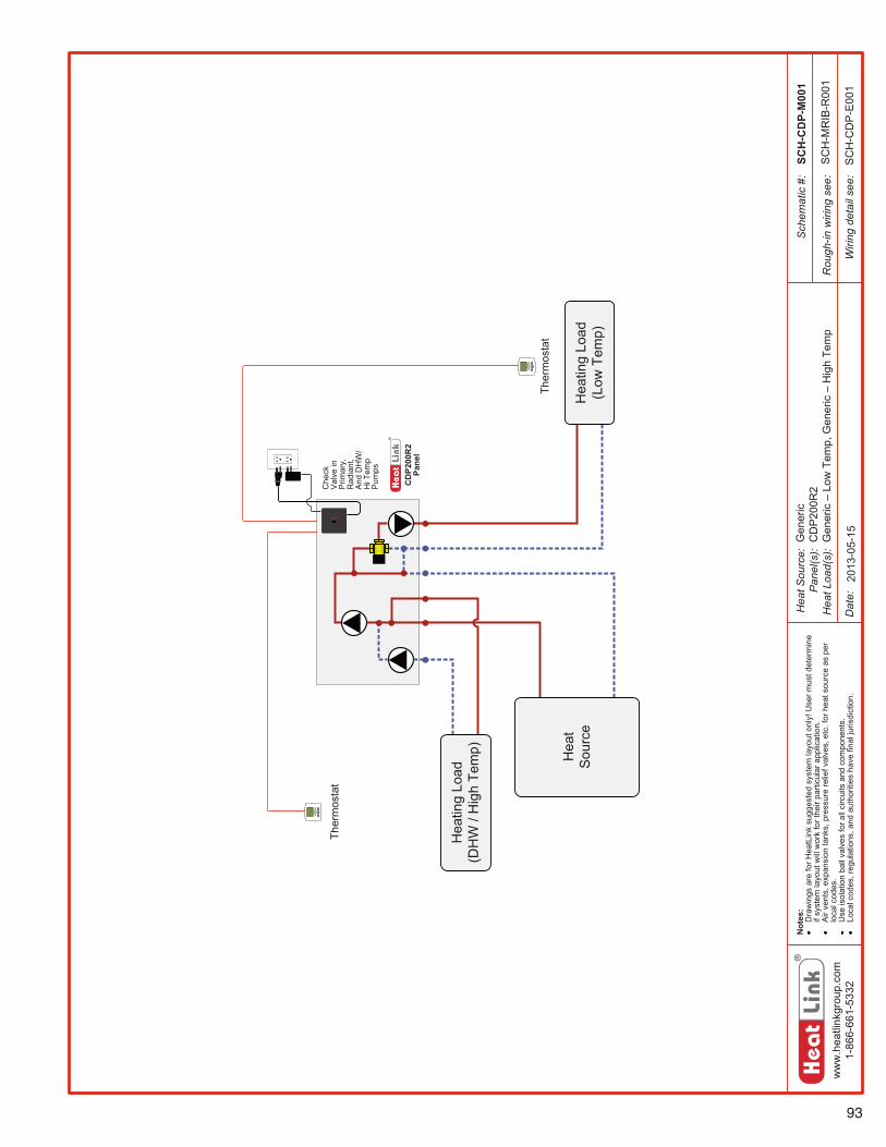
93
ww
w.h
eatli
nkgr
oup.
com
1-86
6-66
1-53
32
Hea
t Sou
rce:
Pan
el(s
):H
eat L
oad(
s):
Sch
emat
ic #
:
Dat
e:
Not
es:
Dra
win
gs a
re fo
r Hea
tLin
k su
gges
ted
syst
em la
yout
onl
y! U
ser m
ust d
eter
min
e if
syst
em la
yout
will
wor
k fo
r the
ir pa
rticu
lar a
pplic
atio
n.A
ir ve
nts,
exp
ansi
on ta
nks,
pre
ssur
e re
lief v
alve
s, e
tc. f
or h
eat s
ourc
e as
per
lo
cal c
odes
.U
se is
olat
ion
ball
valv
es fo
r all
circ
uits
and
com
pone
nts.
Loca
l cod
es, r
egul
atio
ns, a
nd a
utho
ritie
s ha
ve fi
nal j
uris
dict
ion.
Rou
gh-in
wiri
ng s
ee:
Wiri
ng d
etai
l see
:
SCH
-CD
P-M
001
2013
-05-
15
SC
H-M
RIB
-R00
1
SC
H-C
DP
-E00
1
Gen
eric
CD
P20
0R2
Gen
eric
–Lo
w T
emp,
Gen
eric
–H
igh
Tem
p
Ther
mos
tat
Ther
mos
tat
Hea
ting
Load
(Low
Tem
p)
Hea
ting
Load
(DH
W /
Hig
h Te
mp) Hea
tSo
urce
CD
P200
R2
Pane
l
Che
ck
Valv
e in
Pr
imar
y,
Rad
iant
,An
d D
HW
/H
i Tem
p Pu
mps
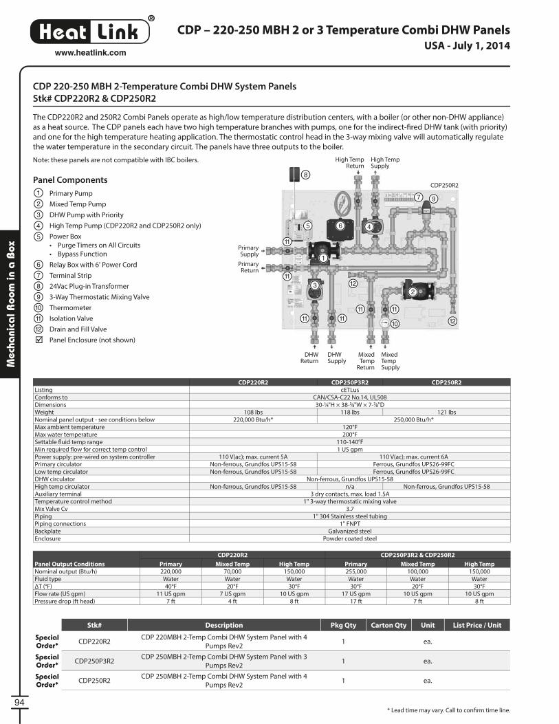
®
LinkHeat
94
www.heatlink.com
Mec
hani
cal R
oom
in a
Box
CDP 220-250 MBH 2-Temperature Combi DHW System Panels
Stk# CDP220R2 & CDP250R2
The CDP220R2 and 250R2 Combi Panels operate as high/low temperature distribution centers, with a boiler (or other non-DHW appliance)
as a heat source. The CDP panels each have two high temperature branches with pumps, one for the indirect-fi red DHW tank (with priority)
and one for the high temperature heating application. The thermostatic control head in the 3-way mixing valve will automatically regulate
the water temperature in the secondary circuit. The panels have three outputs to the boiler.
Note: these panels are not compatible with IBC boilers.
CDP – 220-250 MBH 2 or 3 Temperature Combi DHW Panels
Panel Components
Primary Pump
Mixed Temp Pump
DHW Pump with Priority
High Temp Pump (CDP220R2 and CDP250R2 only)
Power Box
• Purge Timers on All Circuits
• Bypass Function
Relay Box with 6' Power Cord
Terminal Strip
24Vac Plug-in Transformer
3-Way Thermostatic Mixing Valve
Thermometer
Isolation Valve
Drain and Fill Valve
Panel Enclosure (not shown)
1
1
2
2
3
3
5
54 4
6
6
7
7
8
8
9
9
10
1011 11 11
11 11
11
11
12
12
12
Primary Supply
Primary Return
DHW Supply
Mixed Temp Supply
High Temp Supply
DHW Return
Mixed Temp
Return
High Temp Return
CDP220R2 CDP250P3R2 CDP250R2Listing cETLusConforms to CAN/CSA-C22 No.14, UL508Dimensions 30-1⁄4"H × 38-3⁄8"W × 7-7⁄8"DWeight 108 lbs 118 lbs 121 lbsNominal panel output - see conditions below 220,000 Btu/h* 250,000 Btu/h*Max ambient temperature 120°FMax water temperature 200°FSettable fl uid temp range 110-140°FMin required fl ow for correct temp control 1 US gpmPower supply: pre-wired on system controller 110 V(ac); max. current 5A 110 V(ac); max. current 6APrimary circulator Non-ferrous, Grundfos UPS15-58 Ferrous, Grundfos UPS26-99FCLow temp circulator Non-ferrous, Grundfos UPS15-58 Ferrous, Grundfos UPS26-99FCDHW circulator Non-ferrous, Grundfos UPS15-58High temp circulator Non-ferrous, Grundfos UPS15-58 n/a Non-ferrous, Grundfos UPS15-58Auxiliary terminal 3 dry contacts, max. load 1.5ATemperature control method 1" 3-way thermostatic mixing valveMix Valve Cv 3.7Piping 1" 304 Stainless steel tubingPiping connections 1" FNPTBackplate Galvanized steelEnclosure Powder coated steel
Panel Output Conditions
CDP220R2 CDP250P3R2 & CDP250R2
Primary Mixed Temp High Temp Primary Mixed Temp High TempNominal output (Btu/h) 220,000 70,000 150,000 255,000 100,000 150,000Fluid type Water Water Water Water Water WaterΔT (°F) 40°F 20°F 30°F 30°F 20°F 30°FFlow rate (US gpm) 11 US gpm 7 US gpm 10 US gpm 17 US gpm 10 US gpm 10 US gpmPressure drop (ft head) 7 ft 4 ft 8 ft 17 ft 7 ft 8 ft
CDP250R2
* Lead time may vary. Call to confi rm time line.
USA - July 1, 2014
Stk# Description Pkg Qty Carton Qty Unit List Price / Unit
Special Order* CDP220R2
CDP 220MBH 2-Temp Combi DHW System Panel with 4
Pumps Rev21 ea.
Special Order* CDP250P3R2
CDP 250MBH 2-Temp Combi DHW System Panel with 3
Pumps Rev21 ea.
Special Order* CDP250R2
CDP 250MBH 2-Temp Combi DHW System Panel with 4
Pumps Rev21 ea.
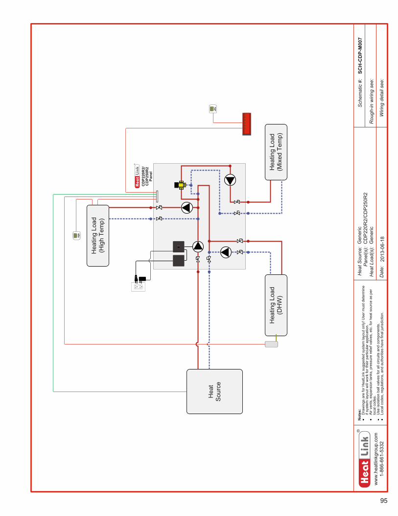
95
ww
w.h
eatli
nkgr
oup.
com
1-86
6-66
1-53
32
Hea
t Sou
rce:
Pan
el(s
):H
eat L
oad(
s):
Sch
emat
ic #
:
Dat
e:
Not
es:
Dra
win
gs a
re fo
r Hea
tLin
k su
gges
ted
syst
em la
yout
onl
y! U
ser m
ust d
eter
min
e if
syst
em la
yout
will
wor
k fo
r the
ir pa
rticu
lar a
pplic
atio
n.A
ir ve
nts,
exp
ansi
on ta
nks,
pre
ssur
e re
lief v
alve
s, e
tc. f
or h
eat s
ourc
e as
per
lo
cal c
odes
.U
se is
olat
ion
ball
valv
es fo
r all
circ
uits
and
com
pone
nts.
Loca
l cod
es, r
egul
atio
ns, a
nd a
utho
ritie
s ha
ve fi
nal j
uris
dict
ion.
Rou
gh-in
wiri
ng s
ee:
Wiri
ng d
etai
l see
:
CD
P220
R2/
CD
P250
R2
Pane
l
SCH
-CD
P-M
007
2013
-06-
18Gen
eric
CD
P22
0R2/
CD
P25
0R2
Gen
eric
Hea
ting
Load
(Mix
ed T
emp)
Hea
ting
Load
(Hig
h Te
mp)
Hea
tSo
urce
Hea
ting
Load
(DH
W)
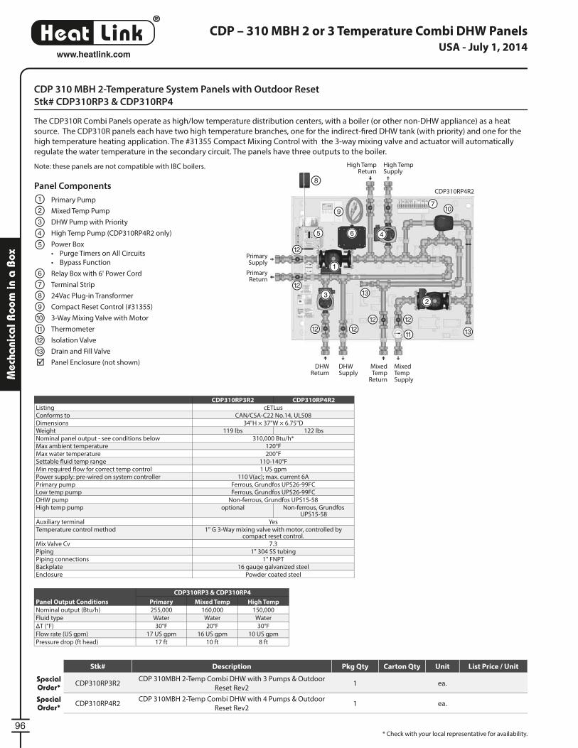
®
LinkHeat
96
www.heatlink.com
Mec
hani
cal R
oom
in a
Box
CDP – 310 MBH 2 or 3 Temperature Combi DHW Panels
CDP 310 MBH 2-Temperature System Panels with Outdoor Reset
Stk# CDP310RP3 & CDP310RP4
The CDP310R Combi Panels operate as high/low temperature distribution centers, with a boiler (or other non-DHW appliance) as a heat
source. The CDP310R panels each have two high temperature branches, one for the indirect-fi red DHW tank (with priority) and one for the
high temperature heating application. The #31355 Compact Mixing Control with the 3-way mixing valve and actuator will automatically
regulate the water temperature in the secondary circuit. The panels have three outputs to the boiler.
Note: these panels are not compatible with IBC boilers.
* Check with your local representative for availability.
CDP310RP3R2 CDP310RP4R2Listing cETLusConforms to CAN/CSA-C22 No.14, UL508Dimensions 34"H × 37"W × 6.75"DWeight 119 lbs 122 lbsNominal panel output - see conditions below 310,000 Btu/h*Max ambient temperature 120°FMax water temperature 200°FSettable fl uid temp range 110-140°FMin required fl ow for correct temp control 1 US gpmPower supply: pre-wired on system controller 110 V(ac); max. current 6APrimary pump Ferrous, Grundfos UPS26-99FCLow temp pump Ferrous, Grundfos UPS26-99FCDHW pump Non-ferrous, Grundfos UPS15-58High temp pump optional Non-ferrous, Grundfos
UPS15-58Auxiliary terminal YesTemperature control method 1" G 3-Way mixing valve with motor, controlled by
compact reset control.Mix Valve Cv 7.3Piping 1" 304 SS tubingPiping connections 1" FNPTBackplate 16 gauge galvanized steelEnclosure Powder coated steel
Panel Output Conditions
CDP310RP3 & CDP310RP4
Primary Mixed Temp High Temp
Nominal output (Btu/h) 255,000 160,000 150,000
Fluid type Water Water Water
ΔT (°F) 30°F 20°F 30°F
Flow rate (US gpm) 17 US gpm 16 US gpm 10 US gpm
Pressure drop (ft head) 17 ft 10 ft 8 ft
1
23
5 46
7
8
109
1112 12
12 12
12
12
13
13
Primary Supply
Primary Return
DHW Supply
Mixed Temp Supply
High Temp Supply
DHW Return
Mixed Temp
Return
High Temp Return
CDP310RP4R2Panel Components
Primary Pump
Mixed Temp Pump
DHW Pump with Priority
High Temp Pump (CDP310RP4R2 only)
Power Box
• Purge Timers on All Circuits
• Bypass Function
Relay Box with 6' Power Cord
Terminal Strip
24Vac Plug-in Transformer
Compact Reset Control (#31355)
3-Way Mixing Valve with Motor
Thermometer
Isolation Valve
Drain and Fill Valve
Panel Enclosure (not shown)
1
2
3
5
4
6
7
8
9
10
11
12
13
USA - July 1, 2014
Stk# Description Pkg Qty Carton Qty Unit List Price / Unit
Special Order* CDP310RP3R2
CDP 310MBH 2-Temp Combi DHW with 3 Pumps & Outdoor
Reset Rev21 ea.
Special Order* CDP310RP4R2
CDP 310MBH 2-Temp Combi DHW with 4 Pumps & Outdoor
Reset Rev21 ea.
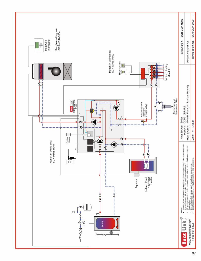
97
ww
w.h
eatli
nkgr
oup.
com
1-86
6-66
1-53
32
Hea
t Sou
rce:
Pan
el(s
):H
eat L
oad(
s):
Sch
emat
ic #
:
Dat
e:
Not
es:
Dra
win
gs a
re fo
r Hea
tLin
k su
gges
ted
syst
em la
yout
onl
y! U
ser m
ust d
eter
min
e if
syst
em la
yout
will
wor
k fo
r the
ir pa
rticu
lar a
pplic
atio
n.A
ir ve
nts,
exp
ansi
on ta
nks,
pre
ssur
e re
lief v
alve
s, e
tc. f
or h
eat s
ourc
e as
per
lo
cal c
odes
.U
se is
olat
ion
ball
valv
es fo
r all
circ
uits
and
com
pone
nts.
Loca
l cod
es, r
egul
atio
ns, a
nd a
utho
ritie
s ha
ve fi
nal j
uris
dict
ion.
Rou
gh-in
wiri
ng s
ee:
Wiri
ng d
etai
l see
:
CD
P310
RP4
R2
Pane
l
T
Out
door
S
enso
r
SCH
-CD
P-M
009
2013
-06-
18S
CH
-CD
P-E
009
Boi
ler
CD
P31
0RP
4R2
IFH
WH
, Fan
Coi
l, R
adia
nt H
eatin
g
Rad
iant
Hea
ting
Man
ifold
Indi
rect
Fire
d H
ot W
ater
H
eate
r
Aqu
asta
t
Ther
mos
tats
Boi
ler
Hea
t/Coo
l Th
erm
osta
t
Rou
gh-in
wiri
ng s
ee:
SC
H-M
RIB
-R00
2
Rou
gh-in
wiri
ng s
ee:
SC
H-M
RIB
-R00
4
Rec
omm
ende
dS
ides
tream
Filt
er
Rec
omm
ende
dPr
essu
re
Bypa
ss V
alve
Rou
gh-in
wiri
ng s
ee:
SC
H-M
RIB
-R00
7
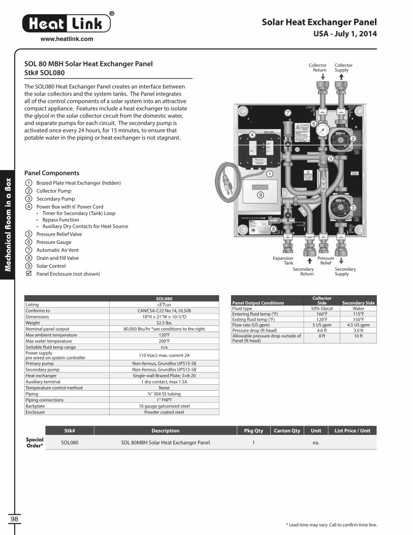
®
LinkHeat
98
www.heatlink.com
Mec
hani
cal R
oom
in a
Box
SOL 80 MBH Solar Heat Exchanger Panel
Stk# SOL080
The SOL080 Heat Exchanger Panel creates an interface between
the solar collectors and the system tanks. The Panel integrates
all of the control components of a solar system into an attractive
compact appliance. Features include a heat exchanger to isolate
the glycol in the solar collector circuit from the domestic water,
and separate pumps for each circuit. The secondary pump is
activated once every 24 hours, for 15 minutes, to ensure that
potable water in the piping or heat exchanger is not stagnant.
Solar Heat Exchanger Panel
* Lead time may vary. Call to confi rm time line.
PressureRelief
ExpansionTank
Panel Components
Brazed Plate Heat Exchanger (hidden)
Collector Pump
Secondary Pump
Power Box with 6' Power Cord
• Timer for Secondary (Tank) Loop
• Bypass Function
• Auxiliary Dry Contacts for Heat Source
Pressure Relief Valve
Pressure Gauge
Automatic Air Vent
Drain and Fill Valve
Solar Control
Panel Enclosure (not shown)
1
2
3
4
5
6
7
8
9
SOL080
Listing cETLus
Conforms to CAN⁄CSA-C22 No.14, UL508
Dimensions 18"H × 21"W × 10-1⁄2"D
Weight 32.5 lbs.
Nominal panel output 80,000 Btu/hr *see conditions to the right
Max ambient temperature 120°F
Max water temperature 200°F
Settable fl uid temp range n/a
Power supplypre wired on system controller
110 V(ac); max. current 2A
Primary pump Non-ferrous, Grundfos UPS15-58
Secondary pump Non-ferrous, Grundfos UPS15-58
Heat exchanger Single-wall Brazed Plate; 3×8-20
Auxiliary terminal 1 dry contact, max 1.5A
Temperature control method None
Piping 3⁄4" 304 SS tubing
Piping connections 1" FNPT
Backplate 16 gauge galvanized steel
Enclosure Powder coated steel
Panel Output ConditionsCollector
Side Secondary SideFluid type 50% Glycol WaterEntering fl uid temp (°F) 160°F 115°FExiting fl uid temp (°F) 120°F 150°FFlow rate (US gpm) 5 US gpm 4.5 US gpmPressure drop (ft head) 4.6 ft 3.0 ftAllowable pressure drop outside of Panel (ft head)
8 ft 10 ft
3
2
1
9
4
5
6
7
8
Secondary Return
Secondary Supply
Collector Return
Collector Supply
USA - July 1, 2014
Stk# Description Pkg Qty Carton Qty Unit List Price / Unit
Special Order* SOL080 SOL 80MBH Solar Heat Exchanger Panel 1 ea.
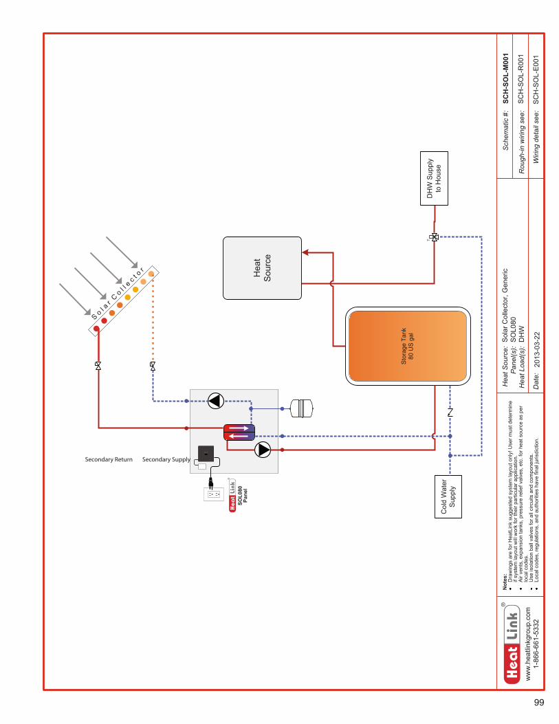
99
ww
w.h
eatli
nkgr
oup.
com
1-86
6-66
1-53
32
Hea
t Sou
rce:
Pan
el(s
):H
eat L
oad(
s):
Sch
emat
ic #
:
Dat
e:
Not
es:
Dra
win
gs a
re fo
r Hea
tLin
k su
gges
ted
syst
em la
yout
onl
y! U
ser m
ust d
eter
min
e if
syst
em la
yout
will
wor
k fo
r the
ir pa
rticu
lar a
pplic
atio
n.A
ir ve
nts,
exp
ansi
on ta
nks,
pre
ssur
e re
lief v
alve
s, e
tc. f
or h
eat s
ourc
e as
per
lo
cal c
odes
.U
se is
olat
ion
ball
valv
es fo
r all
circ
uits
and
com
pone
nts.
Loca
l cod
es, r
egul
atio
ns, a
nd a
utho
ritie
s ha
ve fi
nal j
uris
dict
ion.
Rou
gh-in
wiri
ng s
ee:
Wiri
ng d
etai
l see
:
SOL0
80
Pane
l
Sto
rage
Tan
k
Col
d W
ater
S
uppl
y
T
SCH
-SO
L-M
001
DH
W S
uppl
y to
Hou
se
2013
-03-
22
SC
H-S
OL-
R00
1
SC
H-S
OL-
E00
1
Sol
ar C
olle
ctor
, Gen
eric
SO
L080
DH
W
S ol a
r C o
l l e c
t o r
80 U
S ga
l
Hea
tSo
urce
Secondary Return Secondary Supply
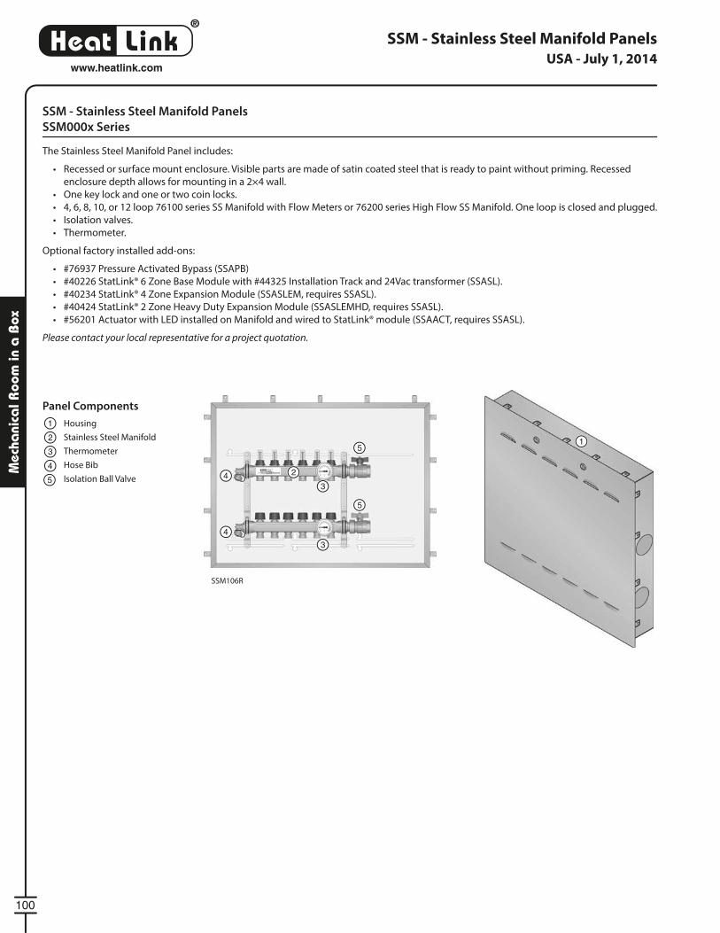
®
LinkHeat
100
www.heatlink.com
Mec
hani
cal R
oom
in a
Box
SSM - Stainless Steel Manifold Panels
SSM106R
SSM - Stainless Steel Manifold Panels
SSM000x Series
The Stainless Steel Manifold Panel includes:
• Recessed or surface mount enclosure. Visible parts are made of satin coated steel that is ready to paint without priming. Recessed
enclosure depth allows for mounting in a 2×4 wall.
• One key lock and one or two coin locks.
• 4, 6, 8, 10, or 12 loop 76100 series SS Manifold with Flow Meters or 76200 series High Flow SS Manifold. One loop is closed and plugged.
• Isolation valves.
• Thermometer.
Optional factory installed add-ons:
• #76937 Pressure Activated Bypass (SSAPB)
• #40226 StatLink® 6 Zone Base Module with #44325 Installation Track and 24Vac transformer (SSASL).
• #40234 StatLink® 4 Zone Expansion Module (SSASLEM, requires SSASL).
• #40424 StatLink® 2 Zone Heavy Duty Expansion Module (SSASLEMHD, requires SSASL).
• #56201 Actuator with LED installed on Manifold and wired to StatLink® module (SSAACT, requires SSASL).
Please contact your local representative for a project quotation.
Panel Components
Housing
Stainless Steel Manifold
Thermometer
Hose Bib
Isolation Ball Valve
1
12
2
3
3
3
44
4
5
5
5
USA - July 1, 2014
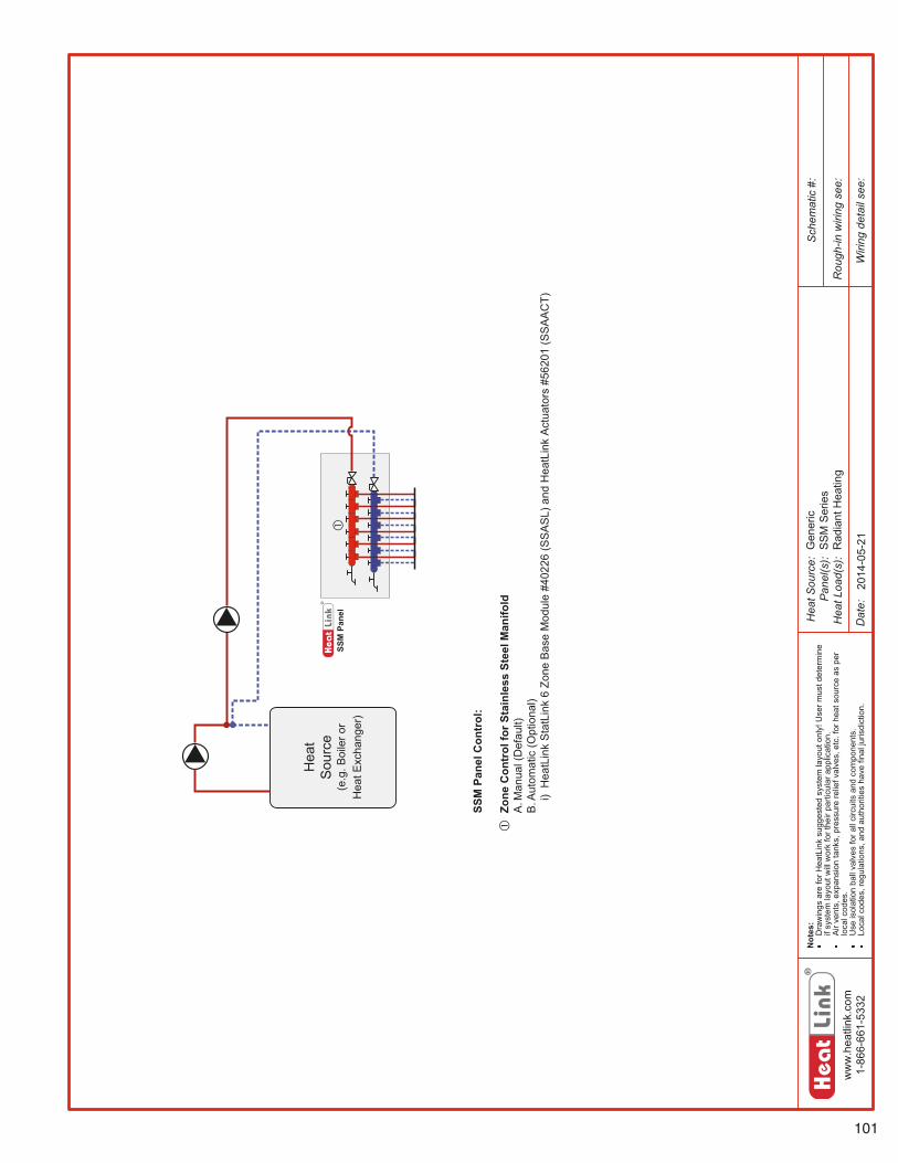
101
ww
w.h
eatli
nk.c
om1-
866-
661-
5332
Hea
tSou
rce:
Pan
el(s
):H
eatL
oad(
s):
Sch
emat
ic#:
Dat
e:
Not
es:
Dra
win
gsar
efo
rHea
tLin
ksu
gges
ted
syst
emla
yout
only
!Use
rmus
tdet
erm
ine
ifsy
stem
layo
utw
illw
ork
fort
heir
parti
cula
rapp
licat
ion.
Air
vent
s,ex
pans
ion
tank
s,pr
essu
rere
liefv
alve
s,et
c.fo
rhea
tsou
rce
aspe
rlo
calc
odes
.U
seis
olat
ion
ball
valv
esfo
rall
circ
uits
and
com
pone
nts.
Loca
lcod
es,r
egul
atio
ns,a
ndau
thor
ities
have
final
juris
dict
ion.
Rou
gh-in
wiri
ngse
e:
Wiri
ngde
tail
see:
SSM
Pane
l
Hea
tS
ourc
e(e
.g.B
oile
ror
Hea
tExc
hang
er)
2014
-05-
21Gen
eric
SS
MS
erie
sR
adia
ntH
eatin
g
SSM
Pane
lCon
trol
:
Zone
Con
trol
forS
tain
less
Stee
lMan
ifold
A.M
anua
l(D
efau
lt)B
.Aut
omat
ic(O
ptio
nal)
i)H
eatL
ink
Sta
tLin
k6
Zone
Bas
eM
odul
e#4
0226
(SS
AS
L)an
dH
eatL
ink
Act
uato
rs#5
6201
(SS
AA
CT)
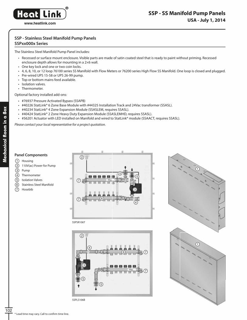
®
LinkHeat
102
www.heatlink.com
Mec
hani
cal R
oom
in a
Box
SSPSR106T
SSPLS106B
Panel Components
Housing
110V(ac) Power for Pump
Pump
Thermometer
Isolation Valves
Stainless Steel Manifold
Hosebib
1
1
12
2
2
3
3
3
4
4
4
5
6
5
5
55
7
6
6
7
7
7
7
SSP - SS Manifold Pump Panels
* Lead time may vary. Call to confi rm time line.
SSP - Stainless Steel Manifold Pump Panels
SSPxx000x Series
The Stainless Steel Manifold Pump Panel includes:
• Recessed or surface mount enclosure. Visible parts are made of satin coated steel that is ready to paint without priming. Recessed
enclosure depth allows for mounting in a 2×6 wall.
• One key lock and one or two coin locks.
• 4, 6, 8, 10, or 12 loop 76100 series SS Manifold with Flow Meters or 76200 series High Flow SS Manifold. One loop is closed and plugged.
• Pre-wired UPS 15-58 or UPS 26-99 pump.
• Top or bottom mains feed available.
• Isolation valves.
• Thermometer.
Optional factory installed add-ons:
• #76937 Pressure Activated Bypass (SSAPB)
• #40226 StatLink® 6 Zone Base Module with #44325 Installation Track and 24Vac transformer (SSASL).
• #40234 StatLink® 4 Zone Expansion Module (SSASLEM, requires SSASL).
• #40424 StatLink® 2 Zone Heavy Duty Expansion Module (SSASLEMHD, requires SSASL).
• #56201 Actuator with LED installed on Manifold and wired to StatLink® module (SSAACT, requires SSASL).
Please contact your local representative for a project quotation.
USA - July 1, 2014
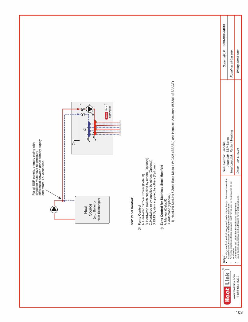
103
ww
w.h
eatli
nk.c
om1-
866-
661-
5332
Hea
tSou
rce:
Pan
el(s
):H
eatL
oad(
s):
Sch
emat
ic#:
Dat
e:
Not
es:
Dra
win
gsar
efo
rHea
tLin
ksu
gges
ted
syst
emla
yout
only
!Use
rmus
tdet
erm
ine
ifsy
stem
layo
utw
illw
ork
fort
heir
parti
cula
rapp
licat
ion.
Air
vent
s,ex
pans
ion
tank
s,pr
essu
rere
liefv
alve
s,et
c.fo
rhea
tsou
rce
aspe
rlo
calc
odes
.U
seis
olat
ion
ball
valv
esfo
rall
circ
uits
and
com
pone
nts.
Loca
lcod
es,r
egul
atio
ns,a
ndau
thor
ities
have
final
juris
dict
ion.
Rou
gh-in
wiri
ngse
e:
Wiri
ngde
tail
see:
SSP
Pane
l
T
Hea
tS
ourc
e(e
.g.B
oile
ror
Hea
tExc
hang
er)
SCH
-SSP
-M01
0
2014
-05-
21Gen
eric
SS
PS
erie
sR
adia
ntH
eatin
g
SSP
Pane
lCon
trol
:
Pum
pC
ontr
olA
.Har
dwire
d12
0Vac
Pow
er(D
efau
lt)B
.Har
dwire
dsw
itch
supp
lied
byot
hers
(Opt
iona
l)C
.Har
dwire
dre
lay
supp
lied
byot
hers
(Opt
iona
l)D
.BM
SS
yste
msu
pplie
dby
othe
rs(O
ptio
nal)
Zone
Con
trol
forS
tain
less
Stee
lMan
ifold
A.M
anua
l(D
efau
lt)B
.Aut
omat
ic(O
ptio
nal)
i)H
eatL
ink
Sta
tLin
k6
Zone
Bas
eM
odul
e#4
0226
(SS
AS
L)an
dH
eatL
ink
Act
uato
rs#5
6201
(SS
AA
CT)
Fora
llS
SP
pane
ls,p
rimar
ypi
ping
with
circ
ulat
orm
usth
ave
nopr
essu
redi
ffere
ntia
lbet
wee
npa
nelp
rimar
ysu
pply
and
retu
rn,i
.e.c
lose
tees
.
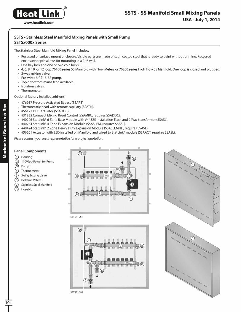
®
LinkHeat
104
www.heatlink.com
Mec
hani
cal R
oom
in a
Box
SSTS - Stainless Steel Manifold Mixing Panels with Small Pump
SSTSx000x Series
The Stainless Steel Manifold Mixing Panel includes:
• Recessed or surface mount enclosure. Visible parts are made of satin coated steel that is ready to paint without priming. Recessed
enclosure depth allows for mounting in a 2×6 wall.
• One key lock and one or two coin locks.
• 4, 6, 8, 10, or 12 loop 76100 series SS Manifold with Flow Meters or 76200 series High Flow SS Manifold. One loop is closed and plugged.
• 3-way mixing valve.
• Pre-wired UPS 15-58 pump.
• Top or bottom mains feed available.
• Isolation valves.
• Thermometer.
Optional factory installed add-ons:
• #76937 Pressure Activated Bypass (SSAPB)
• Thermostatic head with remote capillary (SSATH).
• #56121 DDC Actuator (SSADDC).
• #31355 Compact Mixing Reset Control (SSAMRC, requires SSADDC).
• #40226 StatLink® 6 Zone Base Module with #44325 Installation Track and 24Vac transformer (SSASL).
• #40234 StatLink® 4 Zone Expansion Module (SSASLEM, requires SSASL).
• #40424 StatLink® 2 Zone Heavy Duty Expansion Module (SSASLEMHD, requires SSASL).
• #56201 Actuator with LED installed on Manifold and wired to StatLink® module (SSAACT, requires SSASL).
Please contact your local representative for a project quotation.
SSTS - SS Manifold Small Mixing Panels
SSTSR106T
SSTSS106B
Panel Components
Housing
110V(ac) Power for Pump
Pump
Thermometer
3-Way Mixing Valve
Isolation Valves
Stainless Steel Manifold
Hosebib
1
1
12
2
2
3
3
3
4
4
4
5 5
5
6
6
6
6
6
7
7
7
8
8
8
8
8
USA - July 1, 2014
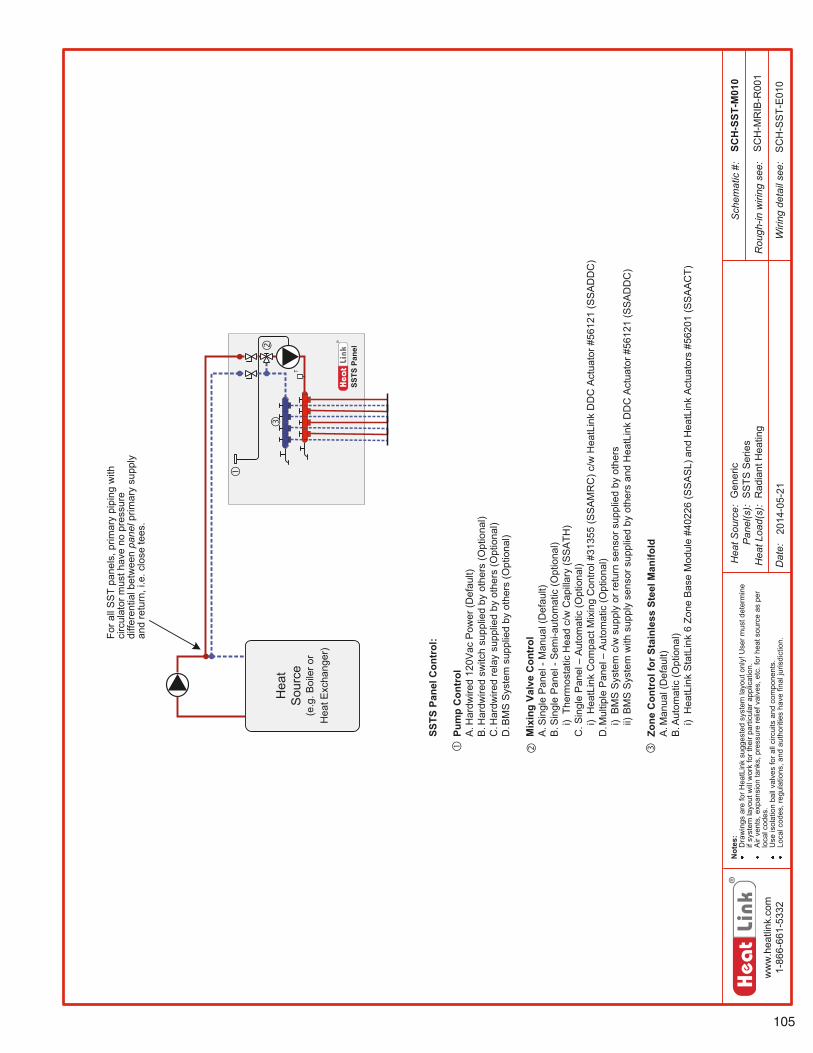
105
ww
w.h
eatli
nk.c
om1-
866-
661-
5332
Hea
tSou
rce:
Pan
el(s
):H
eatL
oad(
s):
Sch
emat
ic#:
Dat
e:
Not
es:
Dra
win
gsar
efo
rHea
tLin
ksu
gges
ted
syst
emla
yout
only
!Use
rmus
tdet
erm
ine
ifsy
stem
layo
utw
illw
ork
fort
heir
parti
cula
rapp
licat
ion.
Air
vent
s,ex
pans
ion
tank
s,pr
essu
rere
liefv
alve
s,et
c.fo
rhea
tsou
rce
aspe
rlo
calc
odes
.U
seis
olat
ion
ball
valv
esfo
rall
circ
uits
and
com
pone
nts.
Loca
lcod
es,r
egul
atio
ns,a
ndau
thor
ities
have
final
juris
dict
ion.
Rou
gh-in
wiri
ngse
e:
Wiri
ngde
tail
see:
SSTS
Pane
l
T
SCH
-SST
-M01
0
2014
-05-
21
SC
H-M
RIB
-R00
1
SC
H-S
ST-
E01
0
Gen
eric
SS
TSS
erie
sR
adia
ntH
eatin
g
SSTS
Pane
lCon
trol
:
Pum
pC
ontr
olA
.Har
dwire
d12
0Vac
Pow
er(D
efau
lt)B
.Har
dwire
dsw
itch
supp
lied
byot
hers
(Opt
iona
l)C
.Har
dwire
dre
lay
supp
lied
byot
hers
(Opt
iona
l)D
.BM
SS
yste
msu
pplie
dby
othe
rs(O
ptio
nal)
Mix
ing
Valv
eC
ontr
olA
.Sin
gle
Pan
el-M
anua
l(D
efau
lt)B
.Sin
gle
Pan
el-S
emi-a
utom
atic
(Opt
iona
l)i)
Ther
mos
tatic
Hea
dc/
wC
apill
ary
(SS
ATH
)C
.Sin
gle
Pan
el–
Aut
omat
ic(O
ptio
nal)
i)H
eatL
ink
Com
pact
Mix
ing
Con
trol#
3135
5(S
SA
MR
C)c
/wH
eatL
ink
DD
CA
ctua
tor#
5612
1(S
SA
DD
C)
D.M
ultip
leP
anel–
Aut
omat
ic(O
ptio
nal)
i)B
MS
Sys
tem
c/w
supp
lyor
retu
rnse
nsor
supp
lied
byot
hers
ii)B
MS
Sys
tem
with
supp
lyse
nsor
supp
lied
byot
hers
and
Hea
tLin
kD
DC
Act
uato
r#56
121
(SS
AD
DC
)
Zone
Con
trol
forS
tain
less
Stee
lMan
ifold
A.M
anua
l(D
efau
lt)B
.Aut
omat
ic(O
ptio
nal)
i)H
eatL
ink
Sta
tLin
k6
Zone
Bas
eM
odul
e#4
0226
(SS
AS
L)an
dH
eatL
ink
Act
uato
rs#5
6201
(SS
AA
CT)
Hea
tS
ourc
e(e
.g.B
oile
ror
Hea
tExc
hang
er)
Fora
llS
ST
pane
ls,p
rimar
ypi
ping
with
circ
ulat
orm
usth
ave
nopr
essu
redi
ffere
ntia
lbet
wee
npa
nelp
rimar
ysu
pply
and
retu
rn,i
.e.c
lose
tees
.
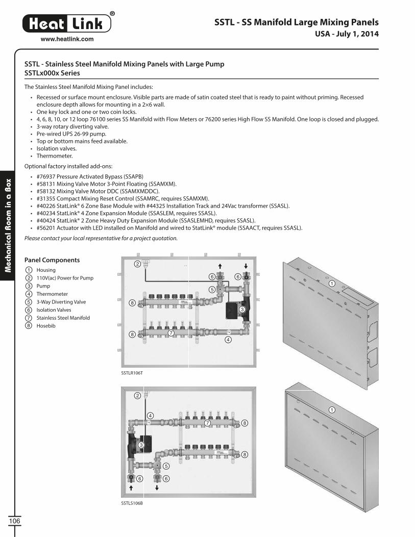
®
LinkHeat
106
www.heatlink.com
Mec
hani
cal R
oom
in a
Box
SSTL - SS Manifold Large Mixing Panels
SSTL - Stainless Steel Manifold Mixing Panels with Large Pump
SSTLx000x Series
The Stainless Steel Manifold Mixing Panel includes:
• Recessed or surface mount enclosure. Visible parts are made of satin coated steel that is ready to paint without priming. Recessed
enclosure depth allows for mounting in a 2×6 wall.
• One key lock and one or two coin locks.
• 4, 6, 8, 10, or 12 loop 76100 series SS Manifold with Flow Meters or 76200 series High Flow SS Manifold. One loop is closed and plugged.
• 3-way rotary diverting valve.
• Pre-wired UPS 26-99 pump.
• Top or bottom mains feed available.
• Isolation valves.
• Thermometer.
Optional factory installed add-ons:
• #76937 Pressure Activated Bypass (SSAPB)
• #58131 Mixing Valve Motor 3-Point Floating (SSAMXM).
• #58132 Mixing Valve Motor DDC (SSAMXMDDC).
• #31355 Compact Mixing Reset Control (SSAMRC, requires SSAMXM).
• #40226 StatLink® 6 Zone Base Module with #44325 Installation Track and 24Vac transformer (SSASL).
• #40234 StatLink® 4 Zone Expansion Module (SSASLEM, requires SSASL).
• #40424 StatLink® 2 Zone Heavy Duty Expansion Module (SSASLEMHD, requires SSASL).
• #56201 Actuator with LED installed on Manifold and wired to StatLink® module (SSAACT, requires SSASL).
Please contact your local representative for a project quotation.
SSTLR106T
SSTLS106B
Panel Components
Housing
110V(ac) Power for Pump
Pump
Thermometer
3-Way Diverting Valve
Isolation Valves
Stainless Steel Manifold
Hosebib
1
1
12
2
2
3
3
3
4
4
4
5
5
5
6
6 6
6 6
7
7
7
8
8
8
8
8
USA - July 1, 2014
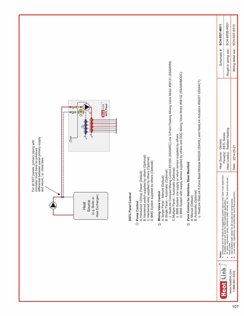
107
ww
w.h
eatli
nk.c
om1-
866-
661-
5332
Hea
tSou
rce:
Pan
el(s
):H
eatL
oad(
s):
Sch
emat
ic#:
Dat
e:
Not
es:
Dra
win
gsar
efo
rHea
tLin
ksu
gges
ted
syst
emla
yout
only
!Use
rmus
tdet
erm
ine
ifsy
stem
layo
utw
illw
ork
fort
heir
parti
cula
rapp
licat
ion.
Air
vent
s,ex
pans
ion
tank
s,pr
essu
rere
liefv
alve
s,et
c.fo
rhea
tsou
rce
aspe
rlo
calc
odes
.U
seis
olat
ion
ball
valv
esfo
rall
circ
uits
and
com
pone
nts.
Loca
lcod
es,r
egul
atio
ns,a
ndau
thor
ities
have
final
juris
dict
ion.
Rou
gh-in
wiri
ngse
e:
Wiri
ngde
tail
see:
SSTL
Pane
l
T
Hea
tS
ourc
e(e
.g.B
oile
ror
Hea
tExc
hang
er)
SCH
-SST
-M01
1
2014
-05-
21
SC
H-M
RIB
-R00
1
SC
H-S
ST-
E01
0
Gen
eric
SS
TLS
erie
sR
adia
ntH
eatin
g
SSTL
Pane
lCon
trol
:
Pum
pC
ontr
olA
.Har
dwire
d12
0Vac
Pow
er(D
efau
lt)B
.Har
dwire
dsw
itch
supp
lied
byot
hers
(Opt
iona
l)C
.Har
dwire
dre
lay
supp
lied
byot
hers
(Opt
iona
l)D
.BM
SS
yste
msu
pplie
dby
othe
rs(O
ptio
nal)
Mix
ing
Valv
eC
ontr
olA
.Sin
gle
Pan
el-M
anua
l(D
efau
lt)B
.Sin
gle
Pan
el–
Aut
omat
ic(O
ptio
nal)
i)H
eatL
ink
Com
pact
Mix
ing
Con
trol#
3135
5(S
SA
MR
C)c
/w3-
Poi
ntFl
oatin
gM
ixin
gV
alve
Mot
or#5
8131
(SS
AM
XM
)C
.Mul
tiple
Pan
el–
Aut
omat
ic(O
ptio
nal)
i)B
MS
Sys
tem
c/w
supp
lyor
retu
rnse
nsor
supp
lied
byot
hers
ii)B
MS
Sys
tem
with
supp
lyse
nsor
supp
lied
byot
hers
and
DD
CM
ixin
gV
alve
Mot
or#5
8132
(SS
AM
XM
DD
C)
Zone
Con
trol
forS
tain
less
Stee
lMan
ifold
A.M
anua
l(D
efau
lt)B
.Aut
omat
ic(O
ptio
nal)
i)H
eatL
ink
Sta
tLin
k6
Zone
Bas
eM
odul
e#4
0226
(SS
AS
L)an
dH
eatL
ink
Act
uato
rs#5
6201
(SS
AA
CT)
Fora
llS
ST
pane
ls,p
rimar
ypi
ping
with
circ
ulat
orm
usth
ave
nopr
essu
redi
ffere
ntia
lbet
wee
npa
nelp
rimar
ysu
pply
and
retu
rn,i
.e.c
lose
tees
.
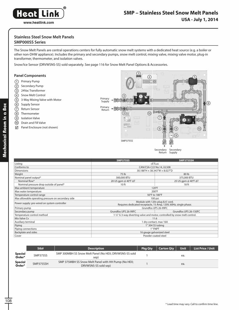
®
LinkHeat
108
www.heatlink.com
Mec
hani
cal R
oom
in a
Box
Stainless Steel Snow Melt Panels
SMP000SS Series
The Snow Melt Panels are central operations centers for fully automatic snow melt systems with a dedicated heat source (e.g. a boiler or
other non-DHW appliance). Includes the primary and secondary pumps, snow melt control, mixing valve, mixing valve motor, plug-in
transformer, thermometer, and isolation valves.
Snow/Ice Sensor (DRVWSNS-SS) sold separately. See page 116 for Snow Melt Panel Options & Accessories.
SMP – Stainless Steel Snow Melt Panels
SMP375SS
SMP375SS SMP375SSH
Listing cETLus
Conforms to CAN/CSA-C22 No.14, UL508
Dimensions 30.188"H × 38.343"W × 8.027"D
Weight 75 lb 80 lb
Nominal panel output* 300,000 BTU 375,000 BTU
Nominal fl ow* 20 US gpm @ 40°F ΔT 25 US gpm @ 40°F ΔT
Nominal pressure drop outside of panel* 10 ft 18 ft
Max ambient temperature 120°F
Max water temperature 200°F
Temperature control range 50°F to 180°F
Max allowable operating pressure on secondary side 100 psi
Power supply: pre-wired on system controllerModule with 120v plug & 6' cord.
Requires dedicated receptacle, 15 Amp, 120V, 60Hz, single phase.
Primary pump Grundfos UPS 26-99FC
Secondary pump Grundfos UPS 26-99FC Grundfos UPS 26-150FC
Temperature control method 1-1⁄4" G 3-way diverting valve and motor, controlled by snow melt control.
Mix Valve Cv 11.6
Auxiliary terminal 1 dry contact, max 16A
Piping 1" 304 SS tubing
Piping connections 1" FNPT
Backplate and sides 16 gauge galvanized steel
Cover Powder coated steel
Panel Components
Primary Pump
Secondary Pump
24Vac Transformer
Snow Melt Control
3-Way Mixing Valve with Motor
Supply Sensor
Return Sensor
Thermometer
Isolation Valve
Drain and Fill Valve
Panel Enclosure (not shown)
1
2
3
5
4
6
7
8
9
10
Primary Supply
Primary Return
Secondary Supply
Secondary Return
1
2
34 5
6
7
8
99 10
109
9
SMP375SS
* Lead time may vary. Call to confi rm time line.
USA - July 1, 2014
Stk# Description Pkg Qty Carton Qty Unit List Price / Unit
Special Order* SMP375SS
SMP 300MBH SS Snow Melt Panel (No HEX; DRVWSNS-SS sold
sep)1 ea.
Special Order* SMP375SSH
SMP 375MBH SS Snow Melt Panel with HH Pump (No HEX;
DRVWSNS-SS sold sep)1 ea.
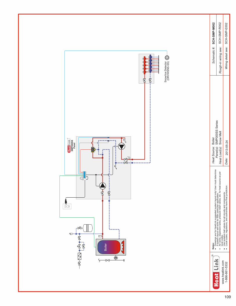
109
ww
w.h
eatli
nk.c
om1-
866-
661-
5332
Hea
tSou
rce:
Pan
el(s
):H
eatL
oad(
s):
Sch
emat
ic#:
Dat
e:
Not
es:
Dra
win
gsar
efo
rHea
tLin
ksu
gges
ted
syst
emla
yout
only
!Use
rmus
tdet
erm
ine
ifsy
stem
layo
utw
illw
ork
fort
heir
parti
cula
rapp
licat
ion.
Air
vent
s,ex
pans
ion
tank
s,pr
essu
rere
liefv
alve
s,et
c.fo
rhea
tsou
rce
aspe
rlo
calc
odes
.U
seis
olat
ion
ball
valv
esfo
rall
circ
uits
and
com
pone
nts.
Loca
lcod
es,r
egul
atio
ns,a
ndau
thor
ities
have
final
juris
dict
ion.
Rou
gh-in
wiri
ngse
e:
Wiri
ngde
tail
see:
SMP0
00SS
Pane
l
T
SCH
-SM
P-M
002
SC
H-S
MP
-R00
2
SC
H-S
MP
-E00
2
Boi
ler
Sno
w/Ic
eD
etec
tor
(DR
VW
SN
S-S
S)
2013
-05-
24Boi
ler
SM
P00
0SS
Ser
ies
Sno
wM
elt
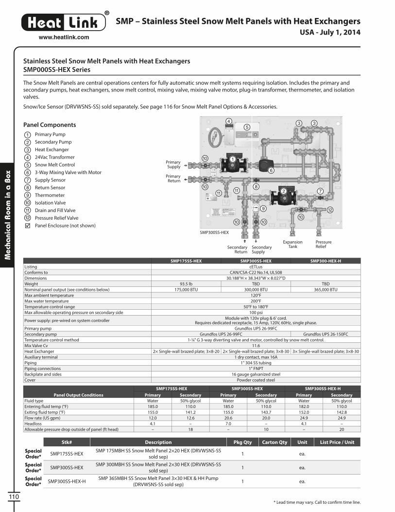
®
LinkHeat
110
www.heatlink.com
Mec
hani
cal R
oom
in a
Box
Stainless Steel Snow Melt Panels with Heat Exchangers
SMP000SS-HEX Series
The Snow Melt Panels are central operations centers for fully automatic snow melt systems requiring isolation. Includes the primary and
secondary pumps, heat exchangers, snow melt control, mixing valve, mixing valve motor, plug-in transformer, thermometer, and isolation
valves.
Snow/Ice Sensor (DRVWSNS-SS) sold separately. See page 116 for Snow Melt Panel Options & Accessories.
SMP – Stainless Steel Snow Melt Panels with Heat Exchangers
SMP175SS-HEX SMP300SS-HEX SMP300-HEX-H
Listing cETLus
Conforms to CAN/CSA-C22 No.14, UL508
Dimensions 30.188"H × 38.343"W × 8.027"D
Weight 93.5 lb TBD TBD
Nominal panel output (see conditions below) 175,000 BTU 300,000 BTU 365,000 BTU
Max ambient temperature 120°F
Max water temperature 200°F
Temperature control range 50°F to 180°F
Max allowable operating pressure on secondary side 100 psi
Power supply: pre-wired on system controllerModule with 120v plug & 6' cord.
Requires dedicated receptacle, 15 Amp, 120V, 60Hz, single phase.
Primary pump Grundfos UPS 26-99FC
Secondary pump Grundfos UPS 26-99FC Grundfos UPS 26-150FC
Temperature control method 1-1⁄4" G 3-way diverting valve and motor, controlled by snow melt control.
Mix Valve Cv 11.6
Heat Exchanger 2× Single-wall brazed plate; 3×8-20 2× Single-wall brazed plate; 3×8-30 3× Single-wall brazed plate; 3×8-30
Auxiliary terminal 1 dry contact, max 16A
Piping 1" 304 SS tubing
Piping connections 1" FNPT
Backplate and sides 16 gauge galvanized steel
Cover Powder coated steel
Panel Output Conditions
SMP175SS-HEX SMP300SS-HEX SMP300SS-HEX-H
Primary Secondary Primary Secondary Primary Secondary
Fluid type Water 50% glycol Water 50% glycol Water 50% glycol
Entering fl uid temp (°F) 185.0 110.0 185.0 110.0 182.0 110.0
Exiting fl uid temp (°F) 155.0 141.2 155.0 143.7 152.0 142.8
Flow rate (US gpm) 12.0 12.6 20.6 20.0 24.9 24.9
Headloss 4.1 – 7.0 – 4.1 –
Allowable pressure drop outside of panel (ft head) – 18 – 10 – 20
Panel Components
Primary Pump
Secondary Pump
Heat Exchanger
24Vac Transformer
Snow Melt Control
3-Way Mixing Valve with Motor
Supply Sensor
Return Sensor
Thermometer
Isolation Valve
Drain and Fill Valve
Pressure Relief Valve
Panel Enclosure (not shown)
1
2
3
5
4
6
7
8
9
10
11
12
SMP300SS-HEX
Primary Supply
Primary Return
Secondary Supply
Pressure Relief
Expansion TankSecondary
Return
1
2
45
3 3
6
78
10
9 12
1110
10
11
1010
* Lead time may vary. Call to confi rm time line.
USA - July 1, 2014
Stk# Description Pkg Qty Carton Qty Unit List Price / Unit
Special Order* SMP175SS-HEX
SMP 175MBH SS Snow Melt Panel 2×20 HEX (DRVWSNS-SS
sold sep)1 ea.
Special Order* SMP300SS-HEX
SMP 300MBH SS Snow Melt Panel 2×30 HEX (DRVWSNS-SS
sold sep)1 ea.
Special Order* SMP300SS-HEX-H
SMP 365MBH SS Snow Melt Panel 3×30 HEX & HH Pump
(DRVWSNS-SS sold sep)1 ea.
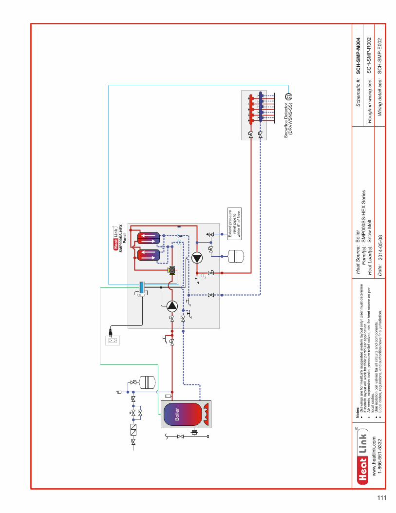
111
ww
w.h
eatli
nk.c
om1-
866-
661-
5332
Hea
tSou
rce:
Pan
el(s
):H
eatL
oad(
s):
Sch
emat
ic#:
Dat
e:
Not
es:
Dra
win
gsar
efo
rHea
tLin
ksu
gges
ted
syst
emla
yout
only
!Use
rmus
tdet
erm
ine
ifsy
stem
layo
utw
illw
ork
fort
heir
parti
cula
rapp
licat
ion.
Air
vent
s,ex
pans
ion
tank
s,pr
essu
rere
liefv
alve
s,et
c.fo
rhea
tsou
rce
aspe
rlo
calc
odes
.U
seis
olat
ion
ball
valv
esfo
rall
circ
uits
and
com
pone
nts.
Loca
lcod
es,r
egul
atio
ns,a
ndau
thor
ities
have
final
juris
dict
ion.
Rou
gh-in
wiri
ngse
e:
Wiri
ngde
tail
see:
SMP0
00SS
-HEX
Pane
l
T
Ext
end
pres
sure
relie
fpip
eto
with
in6"
offlo
or.
SCH
-SM
P-M
004
SC
H-S
MP
-R00
2
SC
H-S
MP
-E00
2
Boi
ler
Sno
w/Ic
eD
etec
tor
(DR
VW
SN
S-S
S)
2014
-05-
08Boi
ler
SM
P00
0SS
-HE
XS
erie
sS
now
Mel
t
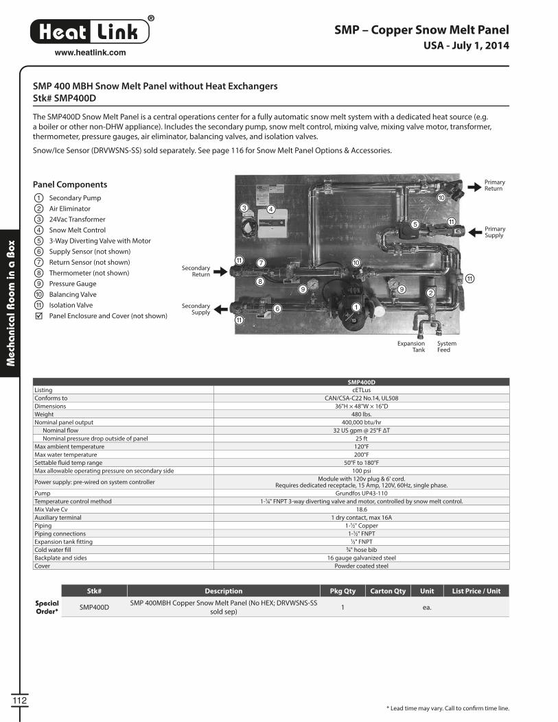
®
LinkHeat
112
www.heatlink.com
Mec
hani
cal R
oom
in a
Box
SMP 400 MBH Snow Melt Panel without Heat Exchangers
Stk# SMP400D
The SMP400D Snow Melt Panel is a central operations center for a fully automatic snow melt system with a dedicated heat source (e.g.
a boiler or other non-DHW appliance). Includes the secondary pump, snow melt control, mixing valve, mixing valve motor, transformer,
thermometer, pressure gauges, air eliminator, balancing valves, and isolation valves.
Snow/Ice Sensor (DRVWSNS-SS) sold separately. See page 116 for Snow Melt Panel Options & Accessories.
SMP – Copper Snow Melt Panel
SMP400D
Listing cETLus
Conforms to CAN/CSA-C22 No.14, UL508
Dimensions 36"H × 48"W × 16"D
Weight 480 lbs.
Nominal panel output 400,000 btu/hr
Nominal fl ow 32 US gpm @ 25°F ΔT
Nominal pressure drop outside of panel 25 ft
Max ambient temperature 120°F
Max water temperature 200°F
Settable fl uid temp range 50°F to 180°F
Max allowable operating pressure on secondary side 100 psi
Power supply: pre-wired on system controllerModule with 120v plug & 6' cord.
Requires dedicated receptacle, 15 Amp, 120V, 60Hz, single phase.
Pump Grundfos UP43-110
Temperature control method 1-1⁄4" FNPT 3-way diverting valve and motor, controlled by snow melt control.
Mix Valve Cv 18.6
Auxiliary terminal 1 dry contact, max 16A
Piping 1-1⁄2" Copper
Piping connections 1-1⁄2" FNPT
Expansion tank fi tting 1⁄2" FNPT
Cold water fi ll 3⁄4" hose bib
Backplate and sides 16 gauge galvanized steel
Cover Powder coated steel
5 11
10
1011
11
299
1
8
3 4
Panel Components
Secondary Pump
Air Eliminator
24Vac Transformer
Snow Melt Control
3-Way Diverting Valve with Motor
Supply Sensor (not shown)
Return Sensor (not shown)
Thermometer (not shown)
Pressure Gauge
Balancing Valve
Isolation Valve
Panel Enclosure and Cover (not shown)
1
2
3
5
4
6
7
8
9
10
11
Primary Return
Secondary Return
Primary Supply
Secondary Supply
6
7
11
* Lead time may vary. Call to confi rm time line.
SystemFeed
ExpansionTank
USA - July 1, 2014
Stk# Description Pkg Qty Carton Qty Unit List Price / Unit
Special Order* SMP400D
SMP 400MBH Copper Snow Melt Panel (No HEX; DRVWSNS-SS
sold sep)1 ea.
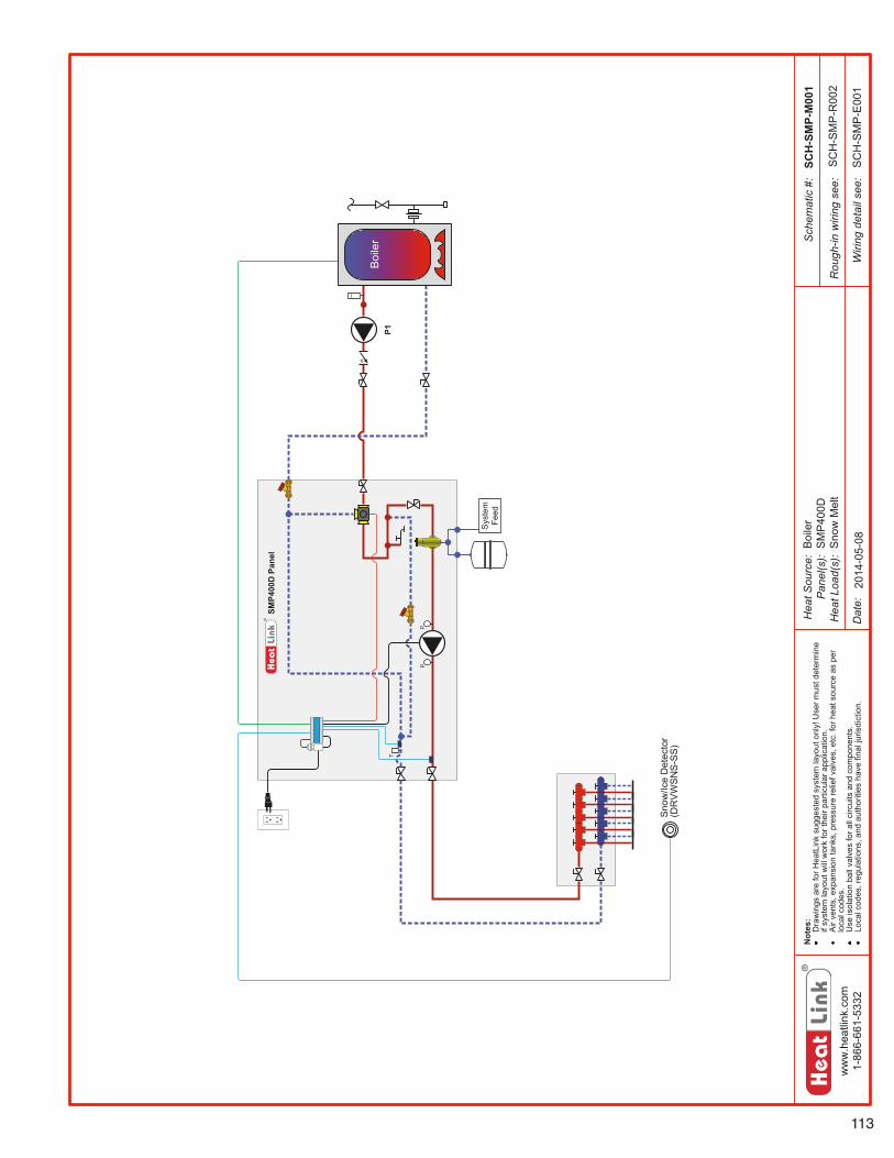
113
ww
w.h
eatli
nk.c
om1-
866-
661-
5332
Hea
tSou
rce:
Pan
el(s
):H
eatL
oad(
s):
Sch
emat
ic#:
Dat
e:
Not
es:
Dra
win
gsar
efo
rHea
tLin
ksu
gges
ted
syst
emla
yout
only
!Use
rmus
tdet
erm
ine
ifsy
stem
layo
utw
illw
ork
fort
heir
parti
cula
rapp
licat
ion.
Air
vent
s,ex
pans
ion
tank
s,pr
essu
rere
liefv
alve
s,et
c.fo
rhea
tsou
rce
aspe
rlo
calc
odes
.U
seis
olat
ion
ball
valv
esfo
rall
circ
uits
and
com
pone
nts.
Loca
lcod
es,r
egul
atio
ns,a
ndau
thor
ities
have
final
juris
dict
ion.
Rou
gh-in
wiri
ngse
e:
Wiri
ngde
tail
see:
PP
Sys
tem
Feed
T
SMP4
00D
Pane
l
SCH
-SM
P-M
001
SC
H-S
MP
-R00
2
SC
H-S
MP
-E00
1
Sno
w/Ic
eD
etec
tor
(DR
VW
SN
S-S
S)
Boi
ler
P1
2014
-05-
08Boi
ler
SM
P40
0DS
now
Mel
t
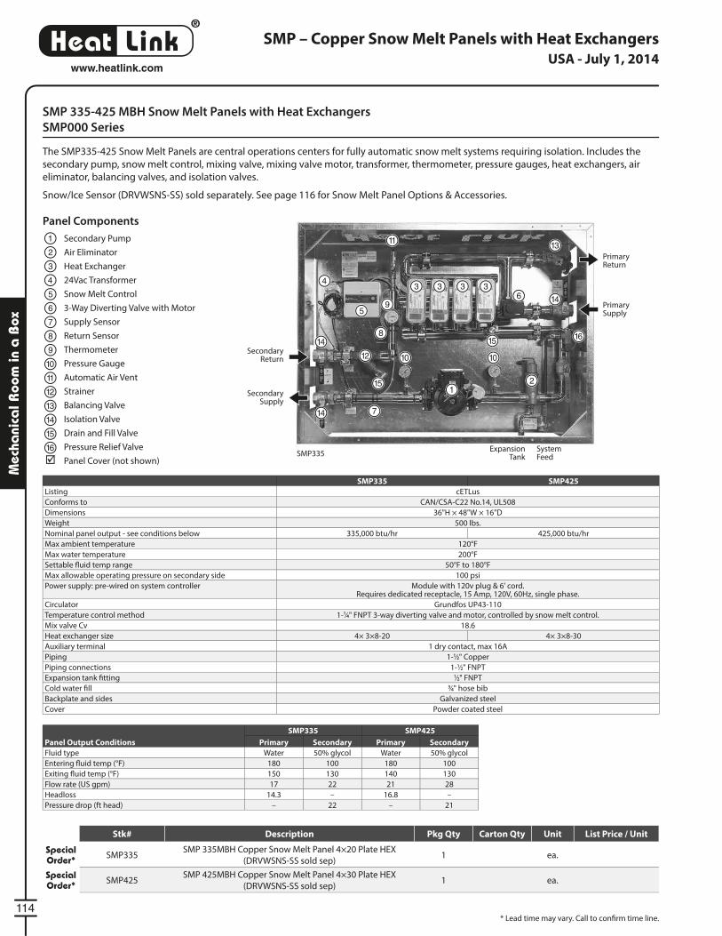
®
LinkHeat
114
www.heatlink.com
Mec
hani
cal R
oom
in a
Box
Primary Return
Secondary Return
Primary Supply
SystemFeed
Secondary Supply
ExpansionTankSMP335
SMP 335-425 MBH Snow Melt Panels with Heat Exchangers
SMP000 Series
The SMP335-425 Snow Melt Panels are central operations centers for fully automatic snow melt systems requiring isolation. Includes the
secondary pump, snow melt control, mixing valve, mixing valve motor, transformer, thermometer, pressure gauges, heat exchangers, air
eliminator, balancing valves, and isolation valves.
Snow/Ice Sensor (DRVWSNS-SS) sold separately. See page 116 for Snow Melt Panel Options & Accessories.
SMP335 SMP425
Listing cETLus
Conforms to CAN/CSA-C22 No.14, UL508
Dimensions 36"H × 48"W × 16"D
Weight 500 lbs.
Nominal panel output - see conditions below 335,000 btu/hr 425,000 btu/hr
Max ambient temperature 120°F
Max water temperature 200°F
Settable fl uid temp range 50°F to 180°F
Max allowable operating pressure on secondary side 100 psi
Power supply: pre-wired on system controller Module with 120v plug & 6' cord.Requires dedicated receptacle, 15 Amp, 120V, 60Hz, single phase.
Circulator Grundfos UP43-110
Temperature control method 1-1⁄4" FNPT 3-way diverting valve and motor, controlled by snow melt control.
Mix valve Cv 18.6
Heat exchanger size 4× 3×8-20 4× 3×8-30
Auxiliary terminal 1 dry contact, max 16A
Piping 1-1⁄2" Copper
Piping connections 1-1⁄2" FNPT
Expansion tank fi tting 1⁄2" FNPT
Cold water fi ll 3⁄4" hose bib
Backplate and sides Galvanized steel
Cover Powder coated steel
Panel Output Conditions
SMP335 SMP425
Primary Secondary Primary Secondary
Fluid type Water 50% glycol Water 50% glycol
Entering fl uid temp (°F) 180 100 180 100
Exiting fl uid temp (°F) 150 130 140 130
Flow rate (US gpm) 17 22 21 28
Headloss 14.3 – 16.8 –
Pressure drop (ft head) – 22 – 21
Panel Components
Secondary Pump
Air Eliminator
Heat Exchanger
24Vac Transformer
Snow Melt Control
3-Way Diverting Valve with Motor
Supply Sensor
Return Sensor
Thermometer
Pressure Gauge
Automatic Air Vent
Strainer
Balancing Valve
Isolation Valve
Drain and Fill Valve
Pressure Relief Valve
Panel Cover (not shown)
1
1
2
2
3
3 3 3 35
5
4 4
6
6
7
7
8 8
9
9
1010 10
11
11
12
12
13
14
14
13
1414
15
16
1615
15
SMP – Copper Snow Melt Panels with Heat Exchangers
* Lead time may vary. Call to confi rm time line.
USA - July 1, 2014
Stk# Description Pkg Qty Carton Qty Unit List Price / Unit
Special Order* SMP335
SMP 335MBH Copper Snow Melt Panel 4×20 Plate HEX
(DRVWSNS-SS sold sep)1 ea.
Special Order* SMP425
SMP 425MBH Copper Snow Melt Panel 4×30 Plate HEX
(DRVWSNS-SS sold sep)1 ea.
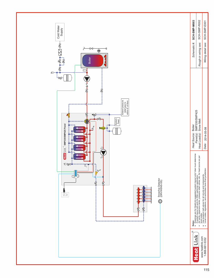
115
ww
w.h
eatli
nk.c
om1-
866-
661-
5332
Hea
tSou
rce:
Pan
el(s
):H
eatL
oad(
s):
Sch
emat
ic#:
Dat
e:
Not
es:
Dra
win
gsar
efo
rHea
tLin
ksu
gges
ted
syst
emla
yout
only
!Use
rmus
tdet
erm
ine
ifsy
stem
layo
utw
illw
ork
fort
heir
parti
cula
rapp
licat
ion.
Air
vent
s,ex
pans
ion
tank
s,pr
essu
rere
liefv
alve
s,et
c.fo
rhea
tsou
rce
aspe
rlo
calc
odes
.U
seis
olat
ion
ball
valv
esfo
rall
circ
uits
and
com
pone
nts.
Loca
lcod
es,r
egul
atio
ns,a
ndau
thor
ities
have
final
juris
dict
ion.
Rou
gh-in
wiri
ngse
e:
Wiri
ngde
tail
see:
PP
SMP3
35/S
MP4
25Pa
nel
Ext
end
pres
sure
relie
fpip
eto
with
in6"
offlo
or.
Sys
tem
Feed
T
SCH
-SM
P-M
003
SC
H-S
MP
-R00
2
SC
H-S
MP
-E00
1
Sno
w/Ic
eD
etec
tor
(DR
VW
SN
S-S
S)
Boi
ler
Col
dW
ater
Sup
ply
2014
-05-
08Boi
ler
SM
P33
5/S
MP
425
Sno
wM
elt
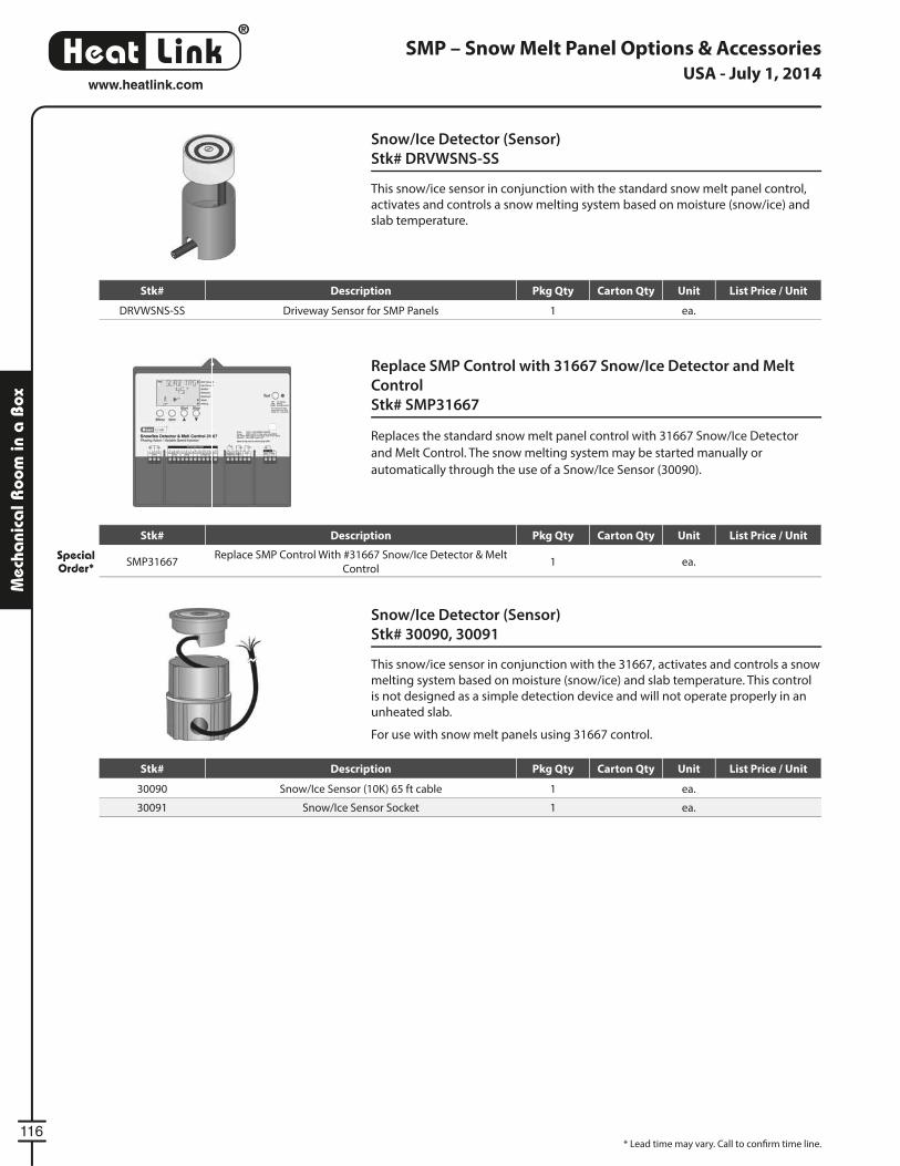
®
LinkHeat
116
www.heatlink.com
Mec
hani
cal R
oom
in a
Box
SMP – Snow Melt Panel Options & Accessories
Snow/Ice Detector (Sensor)
Stk# 30090, 30091
This snow/ice sensor in conjunction with the 31667, ac ti vates and con trols a snow
melting system based on moisture (snow/ice) and slab tem per a ture. This control
is not designed as a simple de tec tion device and will not operate properly in an
un heat ed slab.
For use with snow melt panels using 31667 control.
Snow/Ice Detector (Sensor)
Stk# DRVWSNS-SS
This snow/ice sensor in conjunction with the standard snow melt panel control,
ac ti vates and con trols a snow melting system based on moisture (snow/ice) and
slab tem per a ture.
Replace SMP Control with 31667 Snow/Ice Detector and Melt
Control
Stk# SMP31667
Replaces the standard snow melt panel control with 31667 Snow/Ice Detector
and Melt Control. The snow melting system may be started manually or
automatically through the use of a Snow/Ice Sensor (30090).
* Lead time may vary. Call to confi rm time line.
USA - July 1, 2014
Stk# Description Pkg Qty Carton Qty Unit List Price / Unit
Special Order* SMP31667
Replace SMP Control With #31667 Snow/Ice Detector & Melt
Control1 ea.
Stk# Description Pkg Qty Carton Qty Unit List Price / Unit
30090 Snow/Ice Sensor (10K) 65 ft cable 1 ea.
30091 Snow/Ice Sensor Socket 1 ea.
Stk# Description Pkg Qty Carton Qty Unit List Price / Unit
DRVWSNS-SS Driveway Sensor for SMP Panels 1 ea.
®
LinkHeat
117
www.heatlink.com
Potab
le Wa
ter System
PureLink® Potable Water PEX-a Tubing
PureLink® Plus Blue Stripe PEX-a Tubing - Coils
20000 Series
High molecular crosslinked polyethylene (PEX) with minimum bending radius of 6× the diameter at 68˚F (20˚C). Maximum operating
temperature 180˚F @ 100 psi (82˚C @ 7 bar). Blue printing on 2 sides for identifi cation of cold water lines.
Meets or exceeds ASTM F876/F877/F2023, ASTM E84, CSA B137.5, cNSFus-pw, NSF/ANSI-61, NSF/ANSI-14, Annex G, NSF U.P.Code, ICC-ES,
ICC-PMG, ULC S102.2-2007, IAPMO UPC (1⁄2"), PPI TR-4. The PureLink® Plus PEX-a tubing may also be used with fi ttings that are compliant
with ASTM F1807/F1960/F2080/F2098/F2159 standards.
Minimum bending radius @ 68˚F (20˚C) for: 1⁄2" = 3" (77 mm)3⁄4" = 4-1⁄2" (115 mm)
1" = 6" (153 mm)
For sizes 1-1⁄4" and larger, please see page 119.
For sizes 1-1⁄4" and larger, please see page 119.
USA - July 1, 2014
Stk# Description Pkg Qty Carton Qty Unit List Price / Unit
201051⁄2" 100ft Blue PureLink® Plus UV Stabilized PEX-a
PexCube™6 48 coil
20305 1⁄2" 300ft Blue PureLink® Plus UV Stabilized PEX-a Tubing 1 32 coil
20505 1⁄2" 500ft Blue PureLink® Plus UV Stabilized PEX-a Tubing 1 20 coil
209051⁄2" 1000ft Blue PureLink® Plus UV Stabilized PEX-a
Tubing1 14 coil
201223⁄4" 100ft Blue PureLink® Plus UV Stabilized PEX-a
PexCube™3 48 coil
20322 3⁄4" 300ft Blue PureLink® Plus UV Stabilized PEX-a Tubing 1 14 coil
20522 3⁄4" 500ft Blue PureLink® Plus UV Stabilized PEX-a Tubing 1 9 coil
209223⁄4" 1000ft Blue PureLink® Plus UV Stabilized PEX-a
Tubing1 5 coil
20128 1" 100ft Blue PureLink® Plus UV Stabilized PEX-a Tubing 1 19 coil
20328 1" 300ft Blue PureLink® Plus UV Stabilized PEX-a Tubing 1 9 coil
Stk# Description Pkg Qty Carton Qty Unit List Price / Unit
New! 204051⁄2" 25×12ft Blue PureLink® Plus UV Stabilized PEX-a
Tubing1 20 bundle
202051⁄2" 20×20ft Blue PureLink® Plus UV Stabilized PEX-a
Tubing1 20 bundle
New! 204223⁄4" 10×12ft Blue PureLink® Plus UV Stabilized PEX-a
Tubing1 20 bundle
202223⁄4" 10×20ft Blue PureLink® Plus UV Stabilized PEX-a
Tubing1 20 bundle
New! 204281" 5×12ft Blue PureLink® Plus UV Stabilized PEX-a
Tubing1 20 bundle
202281" 5×20ft Blue PureLink® Plus UV Stabilized PEX-a
Tubing1 20 bundle
Stk# Description Pkg Qty Master Bag Unit Disc. List Price / Unit
Stk# Description Pkg Qty Skid Qty Unit List Price / Unit
®
LinkHeat
118
www.heatlink.com
Pota
ble
Wa
ter
Syst
em
PureLink® Potable Water PEX-a Tubing
PureLink® Plus Red Stripe PEX-a Tubing
21000 Series
High molecular crosslinked polyethylene (PEX) with minimum bending radius of 6× the diameter at 68˚F (20˚C). Maximum operating
temperature 180˚F @ 100 psi (82˚C @ 7 bar). Red printing on 2 sides for identifi cation of hot water lines.
Meets or exceeds ASTM F876/F877/F2023, ASTM E84, CSA B137.5, cNSFus-pw, NSF/ANSI-61, NSF/ANSI-14, Annex G, NSF U.P.Code, ICC-ES,
ICC-PMG, ULC S102.2-2007, IAPMO UPC (1⁄2"), PPI TR-4. The PureLink® Plus PEX-a tubing may also be used with fi ttings that are compliant
with ASTM F1807/F1960/F2080/F2098/F2159 standards.
Minimum bending radius @ 68˚F (20˚C) for: 1⁄2" = 3" (77 mm)3⁄4" = 4-1⁄2" (115 mm)
1" = 6" (153 mm)
For sizes 1-1⁄4" and larger, please see page 119.
For sizes 1-1⁄4" and larger, please see page 119.
USA - July 1, 2014
Stk# Description Pkg Qty Carton Qty Unit List Price / Unit
211051⁄2" 100ft Red PureLink® Plus UV Stabilized PEX-a
PexCube6 48 coil
21305 1⁄2" 300ft Red PureLink® Plus UV Stabilized PEX-a Tubing 1 32 coil
21505 1⁄2" 500ft Red PureLink® Plus UV Stabilized PEX-a Tubing 1 20 coil
219051⁄2" 1000ft Red PureLink® Plus UV Stabilized PEX-a
Tubing1 14 coil
211223⁄4" 100ft Red PureLink® Plus UV Stabilized PEX-a
PexCube3 48 coil
21322 3⁄4" 300ft Red PureLink® Plus UV Stabilized PEX-a Tubing 1 14 coil
21522 3⁄4" 500ft Red PureLink® Plus UV Stabilized PEX-a Tubing 1 9 coil
WSL 219223⁄4" 1000ft Red PureLink® Plus UV Stabilized PEX-a
Tubing1 5 coil
21128 1" 100ft Red PureLink® Plus UV Stabilized PEX-a Tubing 1 19 coil
21328 1" 300ft Red PureLink® Plus UV Stabilized PEX-a Tubing 1 9 coil
Stk# Description Pkg Qty Carton Qty Unit List Price / Unit
New! 214051⁄2" 25×12ft Red PureLink® Plus UV Stabilized PEX-a
Tubing1 20 bundle
212051⁄2" 20×20ft Red PureLink® Plus UV Stabilized PEX-a
Tubing1 20 bundle
New! 214223⁄4" 10×12ft Red PureLink® Plus UV Stabilized PEX-a
Tubing1 20 bundle
212223⁄4" 10×20ft Red PureLink® Plus UV Stabilized PEX-a
Tubing1 20 bundle
21228 1" 5×20ft Red PureLink® Plus UV Stabilized PEX-a Tubing 1 20 bundle
Stk# Description Pkg Qty Master Bag Unit List Price / Unit
Stk# Description Pkg Qty Skid Qty Unit List Price / Unit
®
LinkHeat
119
www.heatlink.com
Potab
le Wa
ter System
PureLink® Plus Large Dimension PEX-a Tubing
20000 Series
High molecular crosslinked polyethylene (PEX) with minimum bending radius of 6× the diameter at 68˚F (20˚C). Maximum operating
temperature 180˚F @ 100 psi (82˚C @ 7 bar). Black printing on 2 sides.
Meets or exceeds ASTM F876/F877/F2023, ASTM E84, CSA B137.5, cNSFus-pw, NSF/ANSI-61, NSF/ANSI-14, Annex G, NSF U.P.Code, ICC-ES,
ICC-PMG, ULC S102.2-2007, PPI TR-4. The PureLink® Plus PEX-a tubing may also be used with fi ttings that are compliant with ASTM F1807/
F1960/F2080/F2098/F2159 standards.
Minimum bending radius @ 68˚F (20˚C) for: 1-1⁄4" = 7-1⁄2" (191 mm)
1-1⁄2" = 9" (229 mm)
2" = 12" (305 mm)
PureLink® Potable Water PEX TubingUSA - July 1, 2014
Stk# Description Pkg Qty Carton Qty Unit List Price / Unit
20135 1-1⁄4" 100ft PureLink® Plus UV Stabilized PEX-a Tubing 1 7 coil
20335 1-1⁄4" 300ft PureLink® Plus UV Stabilized PEX-a Tubing 1 5 coil
20145 1-1⁄2" 100ft PureLink® Plus UV Stabilized PEX-a Tubing 1 5 coil
20345 1-1⁄2" 300ft PureLink® Plus UV Stabilized PEX-a Tubing 1 5 coil
New! 20154 2" 100ft PureLink® Plus UV Stabilized PEX-a Tubing 1 5 coil
New! 20354 2" 300ft PureLink® Plus UV Stabilized PEX-a Tubing 1 3 coil
Stk# Description Pkg Qty Carton Qty Unit List Price / Unit
New! 20435 1-1⁄4" 5×12ft PureLink® Plus UV Stabilized PEX-a Tubing 1 20 bundle
20235 1-1⁄4" 5×20ft PureLink® Plus UV Stabilized PEX-a Tubing 1 20 bundle
20245 1-1⁄2" 5×20ft PureLink® Plus UV Stabilized PEX-a Tubing 1 15 bundle
New! 20254 2" 5×20ft PureLink® Plus UV Stabilized PEX-a Tubing 1 15 bundle
Stk# Description Pkg Qty Skid Qty Unit List Price / Unit
Stk# Description Pkg Qty Master Bag Unit List Price / Unit
Never again deal with the hassle of trying to pull tubing
through conduits. Our pliable PEX-a tubing is available
in a high impact resistant sheath. LinkPure
®
Pipe-in-Pipe
Feed plumbing fi xtures in buildings
of all sizes. Allows for insertion and
withdrawal of inner PEX-a tubing for
perpetual access.
Bathtub
Basin
Toilet
1⁄2" PureLink®
Pipe-in-Pipe3⁄4" PureLink®
Pipe-in-Pipe
®
LinkHeat
121
www.heatlink.com
Potab
le Wa
ter System
PureLink® Pipe-in-Pipe
PureLink® Plus Pipe-in-Pipe
92000 Sheathed Series
PEX-a carrier tubing specifi ed on previous pages. The fl exible, impact resistant PE sheath designed as a raceway for electrical installations
provides mechanical and UV protection to the PEX-a carrier tubing. The sheath allows for easy replacement of the PEX-a carrier tubing if
needed. Red and Blue colored sheaths make for easy identifi cation of hot and cold water lines.
PEX-a carrier tubing meets or exceeds ASTM F876/F877/F2023, CSA B137.5, cNSFus-pw, NSF/ANSI-61, NSF/ANSI-14, Annex G, NSF U.P.Code,
ICC-ES, ICC-PMG, IAPMO UPC (1⁄2"), PPI TR-4. The PureLink® Plus PEX-a tubing may also be used with fi ttings that are compliant with ASTM
F1807/F1960/F2080/F2098/F2159 standards.
Minimum bending radius @ 68˚F (20˚C) for: 1⁄2" = 3" (77 mm)3⁄4" = 4-1⁄2" (115 mm)
1" = 6" (153 mm)
PE sheath is rated to UL94HB “Tests for Flammability of Plastic Materials.”
Corrugated sheath outside diameter for: 1⁄2" = 1515⁄1616" (23 mm)3⁄4" = 1-3⁄8" (35 mm)
1" = 1-1⁄2" (37 mm)
USA - July 1, 2014
Stk# Description Pkg Qty Carton Qty Unit List Price / Unit
92105bs 1⁄2" 100ft Blue PureLink® Plus Pipe-in-Pipe 3 27 coil
92305bs 1⁄2" 300ft Blue PureLink® Plus Pipe-in-Pipe 1 14 coil
92122bs 3⁄4" 100ft Blue PureLink® Plus Pipe-in-Pipe 2 18 coil
92322bs 3⁄4" 300ft Blue PureLink® Plus Pipe-in-Pipe 1 9 coil
92128bs 1" 100ft Blue PureLink® Plus Pipe-in-Pipe 1 7 coil
Stk# Description Pkg Qty Carton Qty Unit List Price / Unit
92105rs 1⁄2" 100ft Red PureLink® Plus Pipe-in-Pipe 3 27 coil
92305rs 1⁄2" 300ft Red PureLink® Plus Pipe-in-Pipe 1 14 coil
92122rs 3⁄4" 100ft Red PureLink® Plus Pipe-in-Pipe 2 18 coil
92322rs 3⁄4" 300ft Red PureLink® Plus Pipe-in-Pipe 1 9 coil
92128rs 1" 100ft Red PureLink® Plus Pipe-in-Pipe 1 7 coil
Stk# Description Pkg Qty Skid Qty Unit List Price / Unit
Stk# Description Pkg Qty Skid Qty Unit List Price / Unit
®
LinkHeat
122
www.heatlink.com
Pota
ble
Wa
ter
Syst
em
EasyFit™ Manifold
Compression Stop Tee
Stk# 22001
The potable water module complete with shut-off . Order shut-off cap (#22180
& #22181) and PEX insert style, tubing to manifold connecters (#23000 series)
separately.
There are 4 shrink-wrapped packages of 5 modules per box.
EasyFit™ 2-Port Tee
Stk# 22002
A 2-port tee with 1⁄2" EasyFit™ connections. Includes 2 nuts.
Mounting Bracket
Stk# 22121
Plastic mounting brackets which allow easy snap-on mounting of manifolds.
EasyFit™ 3-Port Tee
Stk# 22003
A 3-port tee with 1⁄2" EasyFit™ connections. Includes 3 nuts.
USA - July 1, 2014
Stk# Description Pkg Qty Carton Qty Unit List Price / Unit
22001 Compression Stop Tee 1 20 ea.
Stk# Description Pkg Qty Carton Qty Unit List Price / Unit
22002 EasyFit™ 2-Port Tee 1 50 ea.
Stk# Description Pkg Qty Carton Qty Unit List Price / Unit
22003 EasyFit™ 3-Port Tee 1 50 ea.
Stk# Description Pkg Qty Carton Qty Unit List Price / Unit
22121 EasyFit™ Single Mounting Bracket 1 10 ea.
®
LinkHeat
123
www.heatlink.com
Potab
le Wa
ter System
EasyFit™ Manifold Components
Red & Blue Shut-off Caps
Stk# 22180, 22181
Red (#22180) and blue (#22181) colored caps for use with Potable Module Tee
with Compression Stop (#22001). No tools required.
1⁄2" EasyFit™ Supply End Connection
Stk# 22193
O-ring sealing end piece with 1⁄2" EasyFit™ connection. Comes with o-ring.
3⁄4" EasyFit™ Supply End Connection
Stk# 22194
O-ring sealing end piece with 3⁄4" EasyFit™ connection. Comes with o-ring.
3⁄4" EasyFit™ Run End Connection
Stk# 22195
O-ring sealing end piece with 3⁄4" EasyFit™ connection. Comes with o-ring.
Closed End Cap
Stk# 22199
O-ring sealing end piece.
USA - July 1, 2014
Stk# Description Pkg Qty Carton Qty Unit List Price / Unit
22180 Red Shut-off Cap 1 10 ea.
22181 Blue Shut-off Cap 1 10 ea.
Stk# Description Pkg Qty Carton Qty Unit List Price / Unit
22193 1⁄2" EasyFit™ Supply End Connection 1 10 ea.
Stk# Description Pkg Qty Carton Qty Unit List Price / Unit
22194 3⁄4" EasyFit™ Supply End Connection 1 10 ea.
Stk# Description Pkg Qty Carton Qty Unit List Price / Unit
22199 EasyFit™ Manifold Closed End Cap 1 10 ea.
Stk# Description Pkg Qty Carton Qty Unit List Price / Unit
22195 3⁄4" EasyFit™ Run End Connection 1 10 ea.
®
LinkHeat
124
www.heatlink.com
Pota
ble
Wa
ter
Syst
em
EasyFit™ Manifold Components
Tubing to Manifold Connecters
23000 Series
Plastic fi tting is installed into the bottom of the manifold module and is held in
place by the nut. The tubing is then pressed on to this fi tting. SS press sleeves sold
separately.
For use with Compression Stop Tee #22001.
EasyFit™ 1⁄2" Outlet Cap with o-ring
Stk# 23055
Plastic cap with o-ring to seal unused outlet of #22002 & #22003.
Non-Toxic Silicone O-Ring Lubricant
Stk# 79951 & 79952
Lubrication for the manifold o-rings. Non-toxic silicone grease. Highly
recommended for trouble free installation of manifold components.
USA - July 1, 2014
Stk# Description Pkg Qty Carton Qty Unit List Price / Unit
23055 1⁄2" EasyFit™ Outlet Cap with O-ring 10 ea.
Stk# Description Pkg Qty Carton Qty Unit List Price / Unit
23015 1⁄2" PEX Insert Manifold Connecter 5 ea.
23032 3⁄4" PEX Insert Manifold Connecter c/w Nut 5 ea.
Stk# Description Pkg Qty Carton Qty Unit List Price / Unit
79951 100g Bottle Non-toxic Silicone O-ring Lubricant 1 ea.
79952 10g Bottle Non-toxic Silicone O-ring Lubricant 1 ea.
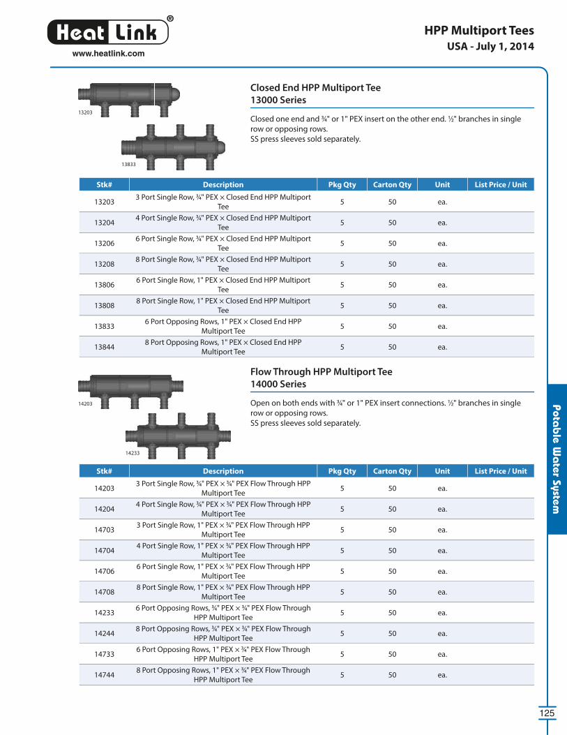
®
LinkHeat
125
www.heatlink.com
Potab
le Wa
ter System
Closed End HPP Multiport Tee
13000 Series
Closed one end and 3⁄4" or 1" PEX insert on the other end. 1⁄2" branches in single
row or opposing rows.
SS press sleeves sold separately.
Flow Through HPP Multiport Tee
14000 Series
Open on both ends with 3⁄4" or 1" PEX insert connections. 1⁄2" branches in single
row or opposing rows.
SS press sleeves sold separately.
HPP Multiport Tees
14203
13203
14233
13833
USA - July 1, 2014
Stk# Description Pkg Qty Carton Qty Unit List Price / Unit
132033 Port Single Row, 3⁄4" PEX × Closed End HPP Multiport
Tee5 50 ea.
132044 Port Single Row, 3⁄4" PEX × Closed End HPP Multiport
Tee5 50 ea.
132066 Port Single Row, 3⁄4" PEX × Closed End HPP Multiport
Tee5 50 ea.
132088 Port Single Row, 3⁄4" PEX × Closed End HPP Multiport
Tee5 50 ea.
138066 Port Single Row, 1" PEX × Closed End HPP Multiport
Tee5 50 ea.
138088 Port Single Row, 1" PEX × Closed End HPP Multiport
Tee5 50 ea.
138336 Port Opposing Rows, 1" PEX × Closed End HPP
Multiport Tee5 50 ea.
138448 Port Opposing Rows, 1" PEX × Closed End HPP
Multiport Tee5 50 ea.
Stk# Description Pkg Qty Carton Qty Unit List Price / Unit
142033 Port Single Row, 3⁄4" PEX × 3⁄4" PEX Flow Through HPP
Multiport Tee5 50 ea.
142044 Port Single Row, 3⁄4" PEX × 3⁄4" PEX Flow Through HPP
Multiport Tee5 50 ea.
147033 Port Single Row, 1" PEX × 3⁄4" PEX Flow Through HPP
Multiport Tee5 50 ea.
147044 Port Single Row, 1" PEX × 3⁄4" PEX Flow Through HPP
Multiport Tee5 50 ea.
147066 Port Single Row, 1" PEX × 3⁄4" PEX Flow Through HPP
Multiport Tee5 50 ea.
147088 Port Single Row, 1" PEX × 3⁄4" PEX Flow Through HPP
Multiport Tee5 50 ea.
142336 Port Opposing Rows, 3⁄4" PEX × 3⁄4" PEX Flow Through
HPP Multiport Tee5 50 ea.
142448 Port Opposing Rows, 3⁄4" PEX × 3⁄4" PEX Flow Through
HPP Multiport Tee5 50 ea.
147336 Port Opposing Rows, 1" PEX × 3⁄4" PEX Flow Through
HPP Multiport Tee5 50 ea.
147448 Port Opposing Rows, 1" PEX × 3⁄4" PEX Flow Through
HPP Multiport Tee5 50 ea.
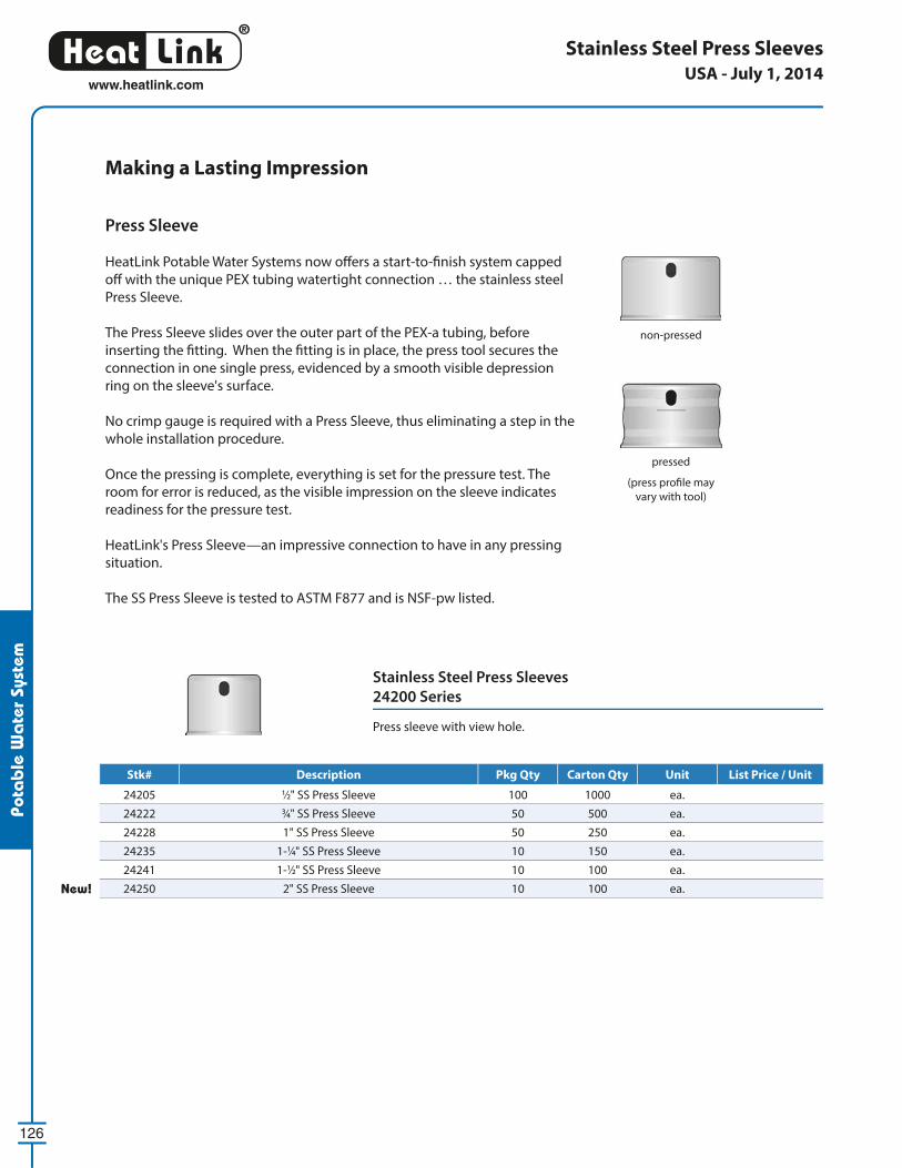
®
LinkHeat
126
www.heatlink.com
Pota
ble
Wa
ter
Syst
em
non-pressed
pressed
(press profi le may
vary with tool)
Making a Lasting Impression
Press Sleeve
HeatLink Potable Water Systems now off ers a start-to-fi nish system capped
off with the unique PEX tubing watertight connection … the stainless steel
Press Sleeve.
The Press Sleeve slides over the outer part of the PEX-a tubing, before
inserting the fi tting. When the fi tting is in place, the press tool secures the
connection in one single press, evidenced by a smooth visible depression
ring on the sleeve's surface.
No crimp gauge is required with a Press Sleeve, thus eliminating a step in the
whole installation procedure.
Once the pressing is complete, everything is set for the pressure test. The
room for error is reduced, as the visible impression on the sleeve indicates
readiness for the pressure test.
HeatLink's Press Sleeve—an impressive connection to have in any pressing
situation.
The SS Press Sleeve is tested to ASTM F877 and is NSF-pw listed.
Stainless Steel Press Sleeves
24200 Series
Press sleeve with view hole.
Stainless Steel Press SleevesUSA - July 1, 2014
Stk# Description Pkg Qty Carton Qty Unit List Price / Unit
24205 1⁄2" SS Press Sleeve 100 1000 ea.
24222 3⁄4" SS Press Sleeve 50 500 ea.
24228 1" SS Press Sleeve 50 250 ea.
24235 1-1⁄4" SS Press Sleeve 10 150 ea.
24241 1-1⁄2" SS Press Sleeve 10 100 ea.
New! 24250 2" SS Press Sleeve 10 100 ea.
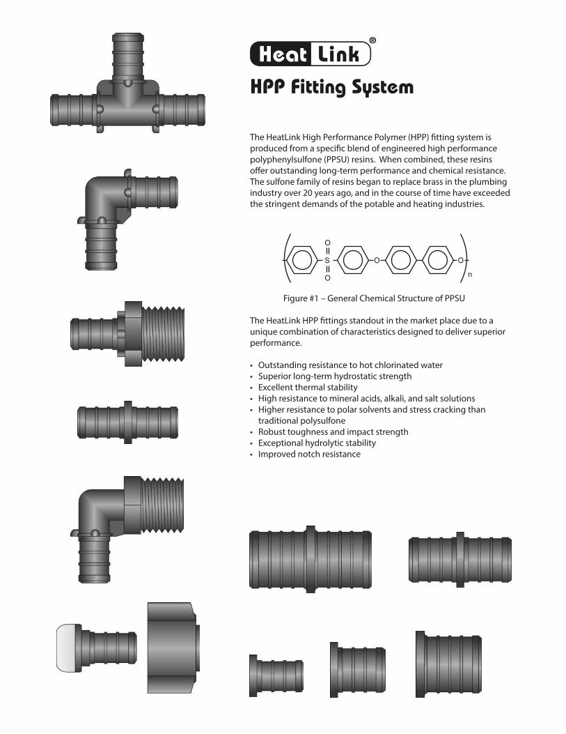
The HeatLink High Performance Polymer (HPP) fi tting system is
produced from a specifi c blend of engineered high performance
polyphenylsulfone (PPSU) resins. When combined, these resins
off er outstanding long-term performance and chemical resistance.
The sulfone family of resins began to replace brass in the plumbing
industry over 20 years ago, and in the course of time have exceeded
the stringent demands of the potable and heating industries.
S
O
O
O O
n
Figure #1 – General Chemical Structure of PPSU
The HeatLink HPP fi ttings standout in the market place due to a
unique combination of characteristics designed to deliver superior
performance.
• Outstanding resistance to hot chlorinated water
• Superior long-term hydrostatic strength
• Excellent thermal stability
• High resistance to mineral acids, alkali, and salt solutions
• Higher resistance to polar solvents and stress cracking than
traditional polysulfone
• Robust toughness and impact strength
• Exceptional hydrolytic stability
• Improved notch resistance
®
LinkHeatHPP Fitting System
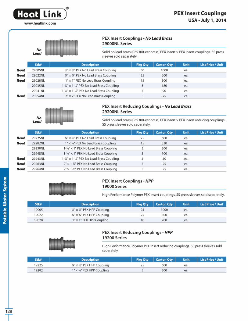
®
LinkHeat
128
www.heatlink.com
Pota
ble
Wa
ter
Syst
em
PEX Insert Couplings
PEX Insert Couplings - No Lead Brass
29000NL Series
Solid no lead brass (C69300-ecobrass) PEX insert × PEX insert couplings. SS press
sleeves sold separately.
PEX Insert Reducing Couplings - No Lead Brass
29200NL Series
Solid no lead brass (C69300-ecobrass) PEX insert × PEX insert reducing couplings.
SS press sleeves sold separately.
PEX Insert Couplings - HPP
19000 Series
High Performance Polymer PEX insert couplings. SS press sleeves sold separately.
PEX Insert Reducing Couplings - HPP
19200 Series
High Performance Polymer PEX insert reducing couplings. SS press sleeves sold
separately.
No Lead
No Lead
USA - July 1, 2014
Stk# Description Pkg Qty Carton Qty Unit List Price / Unit
New! 29005NL 1⁄2" × 1⁄2" PEX No Lead Brass Coupling 50 1000 ea.
New! 29022NL 3⁄4" × 3⁄4" PEX No Lead Brass Coupling 25 500 ea.
New! 29028NL 1" × 1" PEX No Lead Brass Coupling 15 300 ea.
29035NL 1-1⁄4" × 1-1⁄4" PEX No Lead Brass Coupling 5 180 ea.
29041NL 1-1⁄2" × 1-1⁄2" PEX No Lead Brass Coupling 5 90 ea.
New! 29054NL 2" × 2" PEX No Lead Brass Coupling 5 25 ea.
Stk# Description Pkg Qty Carton Qty Unit List Price / Unit
19005 1⁄2" × 1⁄2" PEX HPP Coupling 25 1000 ea.
19022 3⁄4" × 3⁄4" PEX HPP Coupling 25 500 ea.
19028 1" × 1" PEX HPP Coupling 10 200 ea.
Stk# Description Pkg Qty Carton Qty Unit List Price / Unit
New! 29225NL 3⁄4" × 1⁄2" PEX No Lead Brass Coupling 25 600 ea.
New! 29282NL 1" × 3⁄4" PEX No Lead Brass Coupling 15 330 ea.
29238NL 1-1⁄4" × 1" PEX No Lead Brass Coupling 5 200 ea.
29248NL 1-1⁄2" × 1" PEX No Lead Brass Coupling 5 100 ea.
New! 29243NL 1-1⁄2" × 1-1⁄4" PEX No Lead Brass Coupling 5 50 ea.
New! 29263NL 2" × 1-1⁄4" PEX No Lead Brass Coupling 5 25 ea.
New! 29264NL 2" × 1-1⁄2" PEX No Lead Brass Coupling 5 25 ea.
Stk# Description Pkg Qty Carton Qty Unit List Price / Unit
19225 3⁄4" × 1⁄2" PEX HPP Coupling 25 600 ea.
19282 1" × 3⁄4" PEX HPP Coupling 5 300 ea.
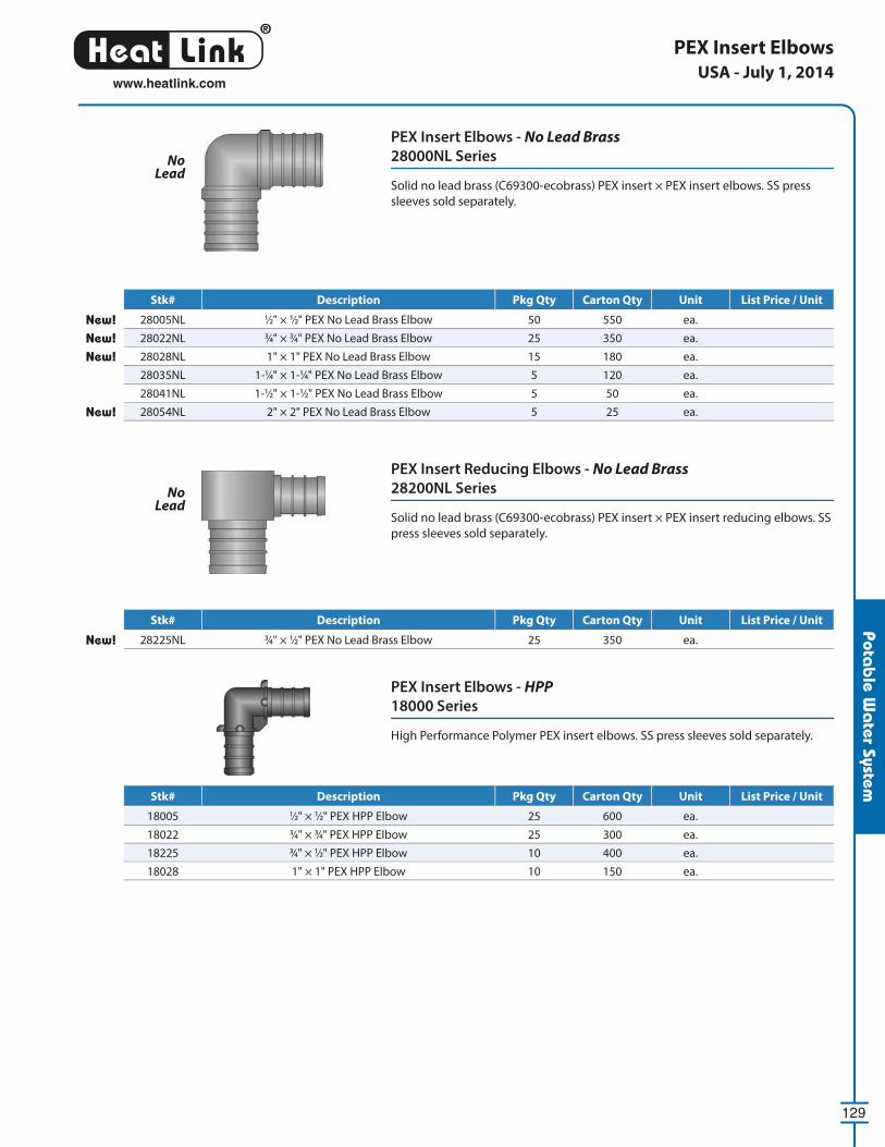
®
LinkHeat
129
www.heatlink.com
Potab
le Wa
ter System
PEX Insert Elbows - No Lead Brass
28000NL Series
Solid no lead brass (C69300-ecobrass) PEX insert × PEX insert elbows. SS press
sleeves sold separately.
PEX Insert Reducing Elbows - No Lead Brass
28200NL Series
Solid no lead brass (C69300-ecobrass) PEX insert × PEX insert reducing elbows. SS
press sleeves sold separately.
PEX Insert Elbows
PEX Insert Elbows - HPP
18000 Series
High Performance Polymer PEX insert elbows. SS press sleeves sold separately.
No Lead
No Lead
USA - July 1, 2014
Stk# Description Pkg Qty Carton Qty Unit List Price / Unit
New! 28005NL 1⁄2" × 1⁄2" PEX No Lead Brass Elbow 50 550 ea.
New! 28022NL 3⁄4" × 3⁄4" PEX No Lead Brass Elbow 25 350 ea.
New! 28028NL 1" × 1" PEX No Lead Brass Elbow 15 180 ea.
28035NL 1-1⁄4" × 1-1⁄4" PEX No Lead Brass Elbow 5 120 ea.
28041NL 1-1⁄2" × 1-1⁄2" PEX No Lead Brass Elbow 5 50 ea.
New! 28054NL 2" × 2" PEX No Lead Brass Elbow 5 25 ea.
Stk# Description Pkg Qty Carton Qty Unit List Price / Unit
18005 1⁄2" × 1⁄2" PEX HPP Elbow 25 600 ea.
18022 3⁄4" × 3⁄4" PEX HPP Elbow 25 300 ea.
18225 3⁄4" × 1⁄2" PEX HPP Elbow 10 400 ea.
18028 1" × 1" PEX HPP Elbow 10 150 ea.
Stk# Description Pkg Qty Carton Qty Unit List Price / Unit
New! 28225NL 3⁄4" × 1⁄2" PEX No Lead Brass Elbow 25 350 ea.
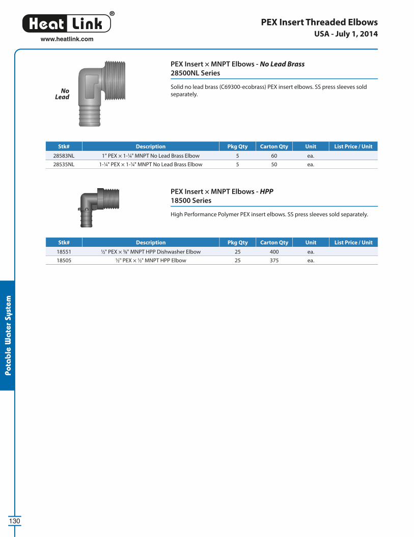
®
LinkHeat
130
www.heatlink.com
Pota
ble
Wa
ter
Syst
em
PEX Insert Threaded Elbows
PEX Insert × MNPT Elbows - HPP
18500 Series
High Performance Polymer PEX insert elbows. SS press sleeves sold separately.
PEX Insert × MNPT Elbows - No Lead Brass
28500NL Series
Solid no lead brass (C69300-ecobrass) PEX insert elbows. SS press sleeves sold
separately.No
Lead
USA - July 1, 2014
Stk# Description Pkg Qty Carton Qty Unit List Price / Unit
18551 1⁄2" PEX × 3⁄8" MNPT HPP Dishwasher Elbow 25 400 ea.
18505 1⁄2" PEX × 1⁄2" MNPT HPP Elbow 25 375 ea.
Stk# Description Pkg Qty Carton Qty Unit List Price / Unit
28583NL 1" PEX × 1-1⁄4" MNPT No Lead Brass Elbow 5 60 ea.
28535NL 1-1⁄4" PEX × 1-1⁄4" MNPT No Lead Brass Elbow 5 50 ea.
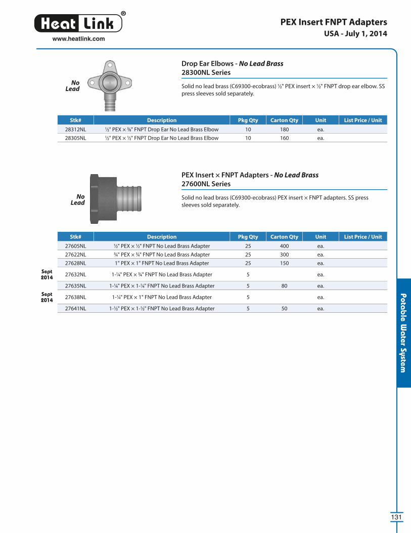
®
LinkHeat
131
www.heatlink.com
Potab
le Wa
ter System
Drop Ear Elbows - No Lead Brass
28300NL Series
Solid no lead brass (C69300-ecobrass) 1⁄2" PEX insert × 1⁄2" FNPT drop ear elbow. SS
press sleeves sold separately.
PEX Insert FNPT Adapters
PEX Insert × FNPT Adapters - No Lead Brass
27600NL Series
Solid no lead brass (C69300-ecobrass) PEX insert × FNPT adapters. SS press
sleeves sold separately.
No Lead
No Lead
USA - July 1, 2014
Stk# Description Pkg Qty Carton Qty Unit List Price / Unit
28312NL 1⁄2" PEX × 3⁄8" FNPT Drop Ear No Lead Brass Elbow 10 180 ea.
28305NL 1⁄2" PEX × 1⁄2" FNPT Drop Ear No Lead Brass Elbow 10 160 ea.
Stk# Description Pkg Qty Carton Qty Unit List Price / Unit
27605NL 1⁄2" PEX × 1⁄2" FNPT No Lead Brass Adapter 25 400 ea.
27622NL 3⁄4" PEX × 3⁄4" FNPT No Lead Brass Adapter 25 300 ea.
27628NL 1" PEX × 1" FNPT No Lead Brass Adapter 25 150 ea.
Sept 2014 27632NL 1-1⁄4" PEX × 3⁄4" FNPT No Lead Brass Adapter 5 ea.
27635NL 1-1⁄4" PEX × 1-1⁄4" FNPT No Lead Brass Adapter 5 80 ea.
Sept 2014 27638NL 1-1⁄4" PEX × 1" FNPT No Lead Brass Adapter 5 ea.
27641NL 1-1⁄2" PEX × 1-1⁄2" FNPT No Lead Brass Adapter 5 50 ea.
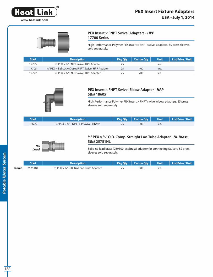
®
LinkHeat
132
www.heatlink.com
Pota
ble
Wa
ter
Syst
em
1⁄2" PEX × 3⁄8" O.D. Comp. Straight Lav. Tube Adapter - NL Brass
Stk# 25751NL
Solid no lead brass (C69300-ecobrass) adapter for connecting faucets. SS press
sleeves sold separately.
PEX Insert × FNPT Swivel Adapters - HPP
17700 Series
High Performance Polymer PEX insert × FNPT swivel adapters. SS press sleeves
sold separately.
PEX Insert × FNPT Swivel Elbow Adapter - HPP
Stk# 18605
High Performance Polymer PEX insert × FNPT swivel elbow adapters. SS press
sleeves sold separately.
PEX Insert Fixture Adapters
No Lead
USA - July 1, 2014
Stk# Description Pkg Qty Carton Qty Unit List Price / Unit
17755 1⁄2" PEX × 1⁄2" FNPT Swivel HPP Adapter 25 ea.
17705 1⁄2" PEX × Ballcock/Closet FNPT Swivel HPP Adapter 25 400 ea.
17722 3⁄4" PEX × 3⁄4" FNPT Swivel HPP Adapter 25 200 ea.
Stk# Description Pkg Qty Carton Qty Unit List Price / Unit
New! 25751NL 1⁄2" PEX × 3⁄8" O.D. No Lead Brass Adapter 25 800 ea.
Stk# Description Pkg Qty Carton Qty Unit List Price / Unit
18605 1⁄2" PEX × 1⁄2" FNPT HPP Swivel Elbow 25 300 ea.
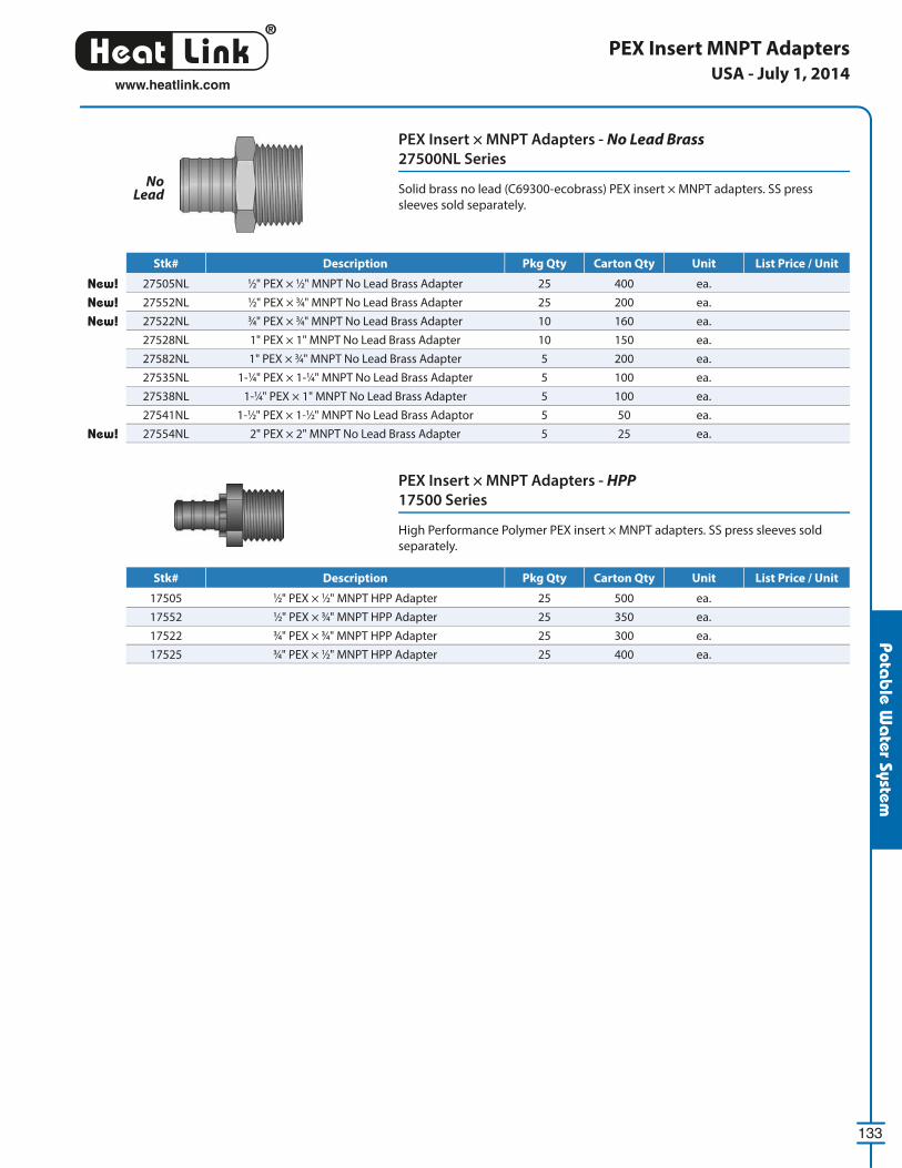
®
LinkHeat
133
www.heatlink.com
Potab
le Wa
ter System
PEX Insert MNPT Adapters
PEX Insert × MNPT Adapters - No Lead Brass
27500NL Series
Solid brass no lead (C69300-ecobrass) PEX insert × MNPT adapters. SS press
sleeves sold separately.
PEX Insert × MNPT Adapters - HPP
17500 Series
High Performance Polymer PEX insert × MNPT adapters. SS press sleeves sold
separately.
No Lead
USA - July 1, 2014
Stk# Description Pkg Qty Carton Qty Unit List Price / Unit
New! 27505NL 1⁄2" PEX × 1⁄2" MNPT No Lead Brass Adapter 25 400 ea.
New! 27552NL 1⁄2" PEX × 3⁄4" MNPT No Lead Brass Adapter 25 200 ea.
New! 27522NL 3⁄4" PEX × 3⁄4" MNPT No Lead Brass Adapter 10 160 ea.
27528NL 1" PEX × 1" MNPT No Lead Brass Adapter 10 150 ea.
27582NL 1" PEX × 3⁄4" MNPT No Lead Brass Adapter 5 200 ea.
27535NL 1-1⁄4" PEX × 1-1⁄4" MNPT No Lead Brass Adapter 5 100 ea.
27538NL 1-1⁄4" PEX × 1" MNPT No Lead Brass Adapter 5 100 ea.
27541NL 1-1⁄2" PEX × 1-1⁄2" MNPT No Lead Brass Adaptor 5 50 ea.
New! 27554NL 2" PEX × 2" MNPT No Lead Brass Adapter 5 25 ea.
Stk# Description Pkg Qty Carton Qty Unit List Price / Unit
17505 1⁄2" PEX × 1⁄2" MNPT HPP Adapter 25 500 ea.
17552 1⁄2" PEX × 3⁄4" MNPT HPP Adapter 25 350 ea.
17522 3⁄4" PEX × 3⁄4" MNPT HPP Adapter 25 300 ea.
17525 3⁄4" PEX × 1⁄2" MNPT HPP Adapter 25 400 ea.
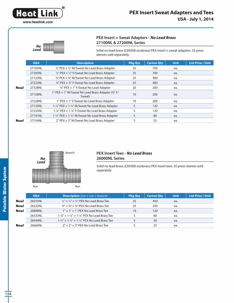
®
LinkHeat
134
www.heatlink.com
Pota
ble
Wa
ter
Syst
em
PEX Insert × Sweat Adapters - No Lead Brass
27100NL & 27200NL Series
Solid no lead brass (C69300-ecobrass) PEX insert × sweat adapters. SS press
sleeves sold separately.
PEX Insert Sweat Adapters and Tees
No Lead
PEX Insert Tees - No Lead Brass
26000NL Series
Solid no lead brass (C69300-ecobrass) PEX insert tees. SS press sleeves sold
separately.
USA - July 1, 2014
Stk# Description Pkg Qty Carton Qty Unit List Price / Unit
27105NL 1⁄2" PEX × 1⁄2" M/Sweat No Lead Brass Adapter 25 700 ea.
27205NL 1⁄2" PEX × 1⁄2" F/Sweat No Lead Brass Adapter 25 700 ea.
27122NL 3⁄4" PEX × 3⁄4" M/Sweat No Lead Brass Adapter 25 400 ea.
27222NL 3⁄4" PEX × 3⁄4" F/Sweat No Lead Brass Adapter 25 400 ea.
New! 27328NL 3⁄4" PEX × 1" F/Sweat No Lead Adapter 20 200 ea.
27128NL1" PEX × 1" M/Sweat No Lead Brass Adapter (3⁄4" F/
Sweat)10 200 ea.
27228NL 1" PEX × 1" F/Sweat No Lead Brass Adapter 10 200 ea.
27135NL 1-1⁄4" PEX × 1-1⁄4" M/Sweat No Lead Brass Adapter 5 120 ea.
27235NL 1-1⁄4" PEX × 1-1⁄4" F/Sweat No Lead Brass Adapter 5 120 ea.
27141NL 1-1⁄2" PEX × 1-1⁄2" M/Sweat No Lead Brass Adapter 5 80 ea.
New! 27154NL 2" PEX × 2" M/Sweat No Lead Brass Adapter 5 25 ea.
Stk# Description Pkg Qty Carton Qty Unit List Price / Unit
New! 26555NL 1⁄2" × 1⁄2" × 1⁄2" PEX No Lead Brass Tee 25 450 ea.
New! 26222NL 3⁄4" × 3⁄4" × 3⁄4" PEX No Lead Brass Tee 25 250 ea.
New! 26888NL 1" × 1" × 1" PEX No Lead Brass Tee 10 120 ea.
26333NL 1-1⁄4" × 1-1⁄4" × 1-1⁄4" PEX No Lead Brass Tee 5 80 ea.
26444NL 1-1⁄2" × 1-1⁄2" × 1-1⁄2" PEX No Lead Brass Tee 5 30 ea.
New! 26666NL 2" × 2" × 2" PEX No Lead Brass Tee 5 25 ea.
Branch
Run Run
No Lead
Stk# Description (run × run × branch) Pkg Qty Carton Qty Unit List Price / Unit
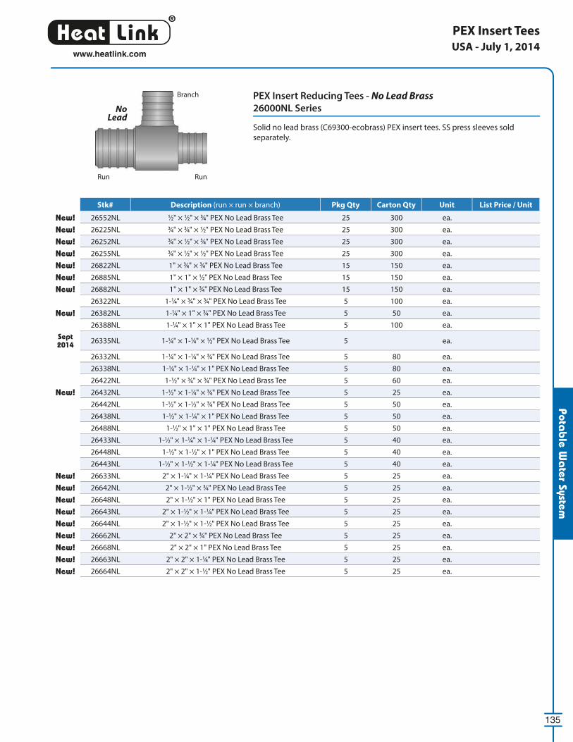
®
LinkHeat
135
www.heatlink.com
Potab
le Wa
ter System
PEX Insert Tees
PEX Insert Reducing Tees - No Lead Brass
26000NL Series
Solid no lead brass (C69300-ecobrass) PEX insert tees. SS press sleeves sold
separately.
USA - July 1, 2014
Stk# Description Pkg Qty Carton Qty Unit List Price / Unit
New! 26552NL 1⁄2" × 1⁄2" × 3⁄4" PEX No Lead Brass Tee 25 300 ea.
New! 26225NL 3⁄4" × 3⁄4" × 1⁄2" PEX No Lead Brass Tee 25 300 ea.
New! 26252NL 3⁄4" × 1⁄2" × 3⁄4" PEX No Lead Brass Tee 25 300 ea.
New! 26255NL 3⁄4" × 1⁄2" × 1⁄2" PEX No Lead Brass Tee 25 300 ea.
New! 26822NL 1" × 3⁄4" × 3⁄4" PEX No Lead Brass Tee 15 150 ea.
New! 26885NL 1" × 1" × 1⁄2" PEX No Lead Brass Tee 15 150 ea.
New! 26882NL 1" × 1" × 3⁄4" PEX No Lead Brass Tee 15 150 ea.
26322NL 1-1⁄4" × 3⁄4" × 3⁄4" PEX No Lead Brass Tee 5 100 ea.
New! 26382NL 1-1⁄4" × 1" × 3⁄4" PEX No Lead Brass Tee 5 50 ea.
26388NL 1-1⁄4" × 1" × 1" PEX No Lead Brass Tee 5 100 ea.
Sept 2014 26335NL 1-1⁄4" × 1-1⁄4" × 1⁄2" PEX No Lead Brass Tee 5 ea.
26332NL 1-1⁄4" × 1-1⁄4" × 3⁄4" PEX No Lead Brass Tee 5 80 ea.
26338NL 1-1⁄4" × 1-1⁄4" × 1" PEX No Lead Brass Tee 5 80 ea.
26422NL 1-1⁄2" × 3⁄4" × 3⁄4" PEX No Lead Brass Tee 5 60 ea.
New! 26432NL 1-1⁄2" × 1-1⁄4" × 3⁄4" PEX No Lead Brass Tee 5 25 ea.
26442NL 1-1⁄2" × 1-1⁄2" × 3⁄4" PEX No Lead Brass Tee 5 50 ea.
26438NL 1-1⁄2" × 1-1⁄4" × 1" PEX No Lead Brass Tee 5 50 ea.
26488NL 1-1⁄2" × 1" × 1" PEX No Lead Brass Tee 5 50 ea.
26433NL 1-1⁄2" × 1-1⁄4" × 1-1⁄4" PEX No Lead Brass Tee 5 40 ea.
26448NL 1-1⁄2" × 1-1⁄2" × 1" PEX No Lead Brass Tee 5 40 ea.
26443NL 1-1⁄2" × 1-1⁄2" × 1-1⁄4" PEX No Lead Brass Tee 5 40 ea.
New! 26633NL 2" × 1-1⁄4" × 1-1⁄4" PEX No Lead Brass Tee 5 25 ea.
New! 26642NL 2" × 1-1⁄2" × 3⁄4" PEX No Lead Brass Tee 5 25 ea.
New! 26648NL 2" × 1-1⁄2" × 1" PEX No Lead Brass Tee 5 25 ea.
New! 26643NL 2" × 1-1⁄2" × 1-1⁄4" PEX No Lead Brass Tee 5 25 ea.
New! 26644NL 2" × 1-1⁄2" × 1-1⁄2" PEX No Lead Brass Tee 5 25 ea.
New! 26662NL 2" × 2" × 3⁄4" PEX No Lead Brass Tee 5 25 ea.
New! 26668NL 2" × 2" × 1" PEX No Lead Brass Tee 5 25 ea.
New! 26663NL 2" × 2" × 1-1⁄4" PEX No Lead Brass Tee 5 25 ea.
New! 26664NL 2" × 2" × 1-1⁄2" PEX No Lead Brass Tee 5 25 ea.
Branch
Run Run
No Lead
Stk# Description (run × run × branch) Pkg Qty Carton Qty Unit List Price / Unit
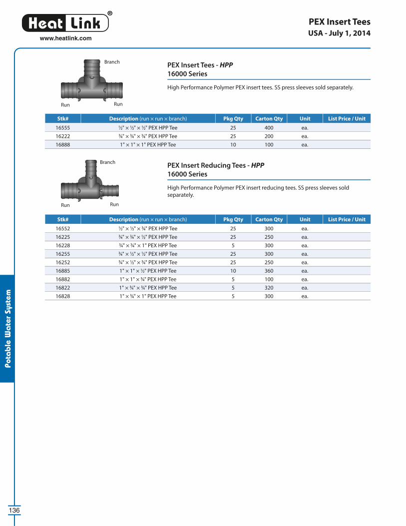
®
LinkHeat
136
www.heatlink.com
Pota
ble
Wa
ter
Syst
em
PEX Insert Tees
PEX Insert Tees - HPP
16000 Series
High Performance Polymer PEX insert tees. SS press sleeves sold separately.
Branch
Run Run
PEX Insert Reducing Tees - HPP
16000 Series
High Performance Polymer PEX insert reducing tees. SS press sleeves sold
separately.
Branch
Run Run
USA - July 1, 2014
Stk# Description Pkg Qty Carton Qty Unit List Price / Unit
16555 1⁄2" × 1⁄2" × 1⁄2" PEX HPP Tee 25 400 ea.
16222 3⁄4" × 3⁄4" × 3⁄4" PEX HPP Tee 25 200 ea.
16888 1" × 1" × 1" PEX HPP Tee 10 100 ea.
Stk# Description Pkg Qty Carton Qty Unit List Price / Unit
16552 1⁄2" × 1⁄2" × 3⁄4" PEX HPP Tee 25 300 ea.
16225 3⁄4" × 3⁄4" × 1⁄2" PEX HPP Tee 25 250 ea.
16228 3⁄4" × 3⁄4" × 1" PEX HPP Tee 5 300 ea.
16255 3⁄4" × 1⁄2" × 1⁄2" PEX HPP Tee 25 300 ea.
16252 3⁄4" × 1⁄2" × 3⁄4" PEX HPP Tee 25 250 ea.
16885 1" × 1" × 1⁄2" PEX HPP Tee 10 360 ea.
16882 1" × 1" × 3⁄4" PEX HPP Tee 5 100 ea.
16822 1" × 3⁄4" × 3⁄4" PEX HPP Tee 5 320 ea.
16828 1" × 3⁄4" × 1" PEX HPP Tee 5 300 ea.
Stk# Description (run × run × branch) Pkg Qty Carton Qty Unit List Price / Unit
Stk# Description (run × run × branch) Pkg Qty Carton Qty Unit List Price / Unit
®
LinkHeat
137
www.heatlink.com
Potab
le Wa
ter System
PEX Insert Plugs - No Lead Brass
25000NL Series
Solid no lead brass (C69300-ecobrass) PEX insert plug. SS press sleeves sold
separately.
PEX Insert Plugs - HPP
15000 Series
High Performance Polymer PEX insert plugs. SS press sleeves sold separately.
PEX Insert PlugsUSA - July 1, 2014
Stk# Description Pkg Qty Carton Qty Unit List Price / Unit
New! 25005NL 1⁄2" PEX No Lead Brass Plug 50 1200 ea.
New! 25022NL 3⁄4" PEX No Lead Brass Plug 25 1000 ea.
New! 25028NL 1" PEX No Lead Brass Plug 15 510 ea.
25035NL 1-1⁄4" PEX No Lead Brass Plug 5 260 ea.
25041NL 1-1⁄2" PEX No Lead Brass Plug 5 110 ea.
New! 25054NL 2" PEX No Lead Brass Plug 5 50 ea.
Stk# Description Pkg Qty Carton Qty Unit List Price / Unit
15005 1⁄2" PEX HPP Plug 25 2000 ea.
15022 3⁄4" PEX HPP Plug 25 1000 ea.
15028 1" PEX HPP Plug 5 500 ea.
No Lead
®
LinkHeat
138
www.heatlink.com
Pota
ble
Wa
ter
Syst
em
Ball Valves
Chrome Plated Straight Ball Valve - No Lead Brass
Stk #23505NL
No lead brass (C69300-ecobrass) 1⁄2" PEX × 3⁄8" O.D. compression, plated straight
ball valve. SS press sleeves sold separately.
Chrome Plated Angle Ball Valve - No Lead Brass
Stk# 23605NL
No lead brass (C69300-ecobrass) 1⁄2" PEX × 3⁄8" O.D. compression, plated angle ball
valve. SS press sleeves sold separately.
No Lead
No Lead
PEX Barb Straight Ball Valves - No Lead Brass
23700NL Series
No lead brass (C69300-ecobrass) valve. SS press sleeves sold separately.
Straight Ball Valve - No Lead Brass
Stk# 23905NL
No lead brass (C69300-ecobrass) 1⁄2" PEX × 1⁄4" O.D. compression, straight ball valve.
SS press sleeves sold separately.
No Lead
No Lead
USA - July 1, 2014
Stk# Description Pkg Qty Carton Qty Unit List Price / Unit
23505NL1⁄2" PEX × 3⁄8" O.D. No Lead Brass Plated Straight Ball
Valve24 144 ea.
Stk# Description Pkg Qty Carton Qty Unit List Price / Unit
23605NL 1⁄2" PEX × 3⁄8" O.D. No Lead Brass Plated Angle Ball Valve 24 144 ea.
Stk# Description Pkg Qty Carton Qty Unit List Price / Unit
New! 23905NL 1⁄2" PEX × 1⁄4" O.D. No Lead Straight Ball Valve 24 144 ea.
Stk# Description Pkg Qty Carton Qty Unit List Price / Unit
23705NL 1⁄2" PEX Straight No Lead Brass Ball Valve 24 144 ea.
23722NL 3⁄4" PEX Straight No Lead Brass Ball Valve 24 144 ea.
®
LinkHeat
139
www.heatlink.com
Potab
le Wa
ter System
Ball Valves
1⁄2" PEX × 1⁄2" M/Sweat Straight Ball Valve - No Lead Brass
Stk# 23405NL
No lead brass (C69300-ecobrass) 1⁄2" PEX × 1⁄2" male sweat ball valve. SS press
sleeves sold separately.
Stop and Waste Valves - No Lead Brass
23700NL Series
No lead brass (C69300-ecobrass) stop and waste valves. SS press sleeves sold
separately.
3⁄4" PEX × 3⁄4" MNPT Straight Ball Valve - No Lead Brass
Stk# 23422NL
No lead brass (C69300-ecobrass) 3⁄4" PEX × 3⁄4" male NPT ball valve. SS press sleeves
sold separately.
No Lead
No Lead
No Lead
USA - July 1, 2014
Stk# Description Pkg Qty Carton Qty Unit List Price / Unit
New! 23405NL 1⁄2" PEX × 1⁄2" No Lead M/Sweat Straight Ball Valve 24 144 ea.
Stk# Description Pkg Qty Carton Qty Unit List Price / Unit
New! 23775NL 1⁄2" PEX No Lead Stop and Waste Valve 24 144 ea.
New! 23772NL 3⁄4" PEX No Lead Stop and Waste Valve 24 144 ea.
Stk# Description Pkg Qty Carton Qty Unit List Price / Unit
New! 23422NL 3⁄4" PEX × 3⁄4" MNPT No Lead Straight Ball Valve 24 144 ea.
®
LinkHeat
140
www.heatlink.com
Pota
ble
Wa
ter
Syst
em
1⁄2" PEX Insert × Male Sweat, 3" × 4" Stubout Elbow
Stk# 28234
Copper stubout elbow allows for 90˚ transitions between fi xtures and wall
cavities. SS press sleeves sold separately.
1⁄2" PEX Insert × Closed, 3" × 6" Stubout Elbow with Edge Bracket
Stk# 28205
Copper stubout elbow allows for 90˚ transitions between fi xtures and wall
cavities. SS press sleeves sold separately.
1⁄2" PEX Insert × Closed, 3" × 6" Stubout Elbow
Stk# 28206
Copper stubout elbow allows for 90˚ transitions between fi xtures and wall
cavities. SS press sleeves sold separately.
Stubout ElbowsUSA - July 1, 2014
Stk# Description Pkg Qty Carton Qty Unit List Price / Unit
28205 1⁄2" PEX Barb Stubout Elbow with Edge Bracket 25 50 ea.
Stk# Description Pkg Qty Carton Qty Unit List Price / Unit
28206 1⁄2" PEX × Closed, 3-1⁄2" × 6" Stub-out Elbow 50 ea.
Stk# Description Pkg Qty Carton Qty Unit List Price / Unit
28234 1⁄2" PEX × M/Sweat, 3" × 4" Stub-out Elbow 25 ea.
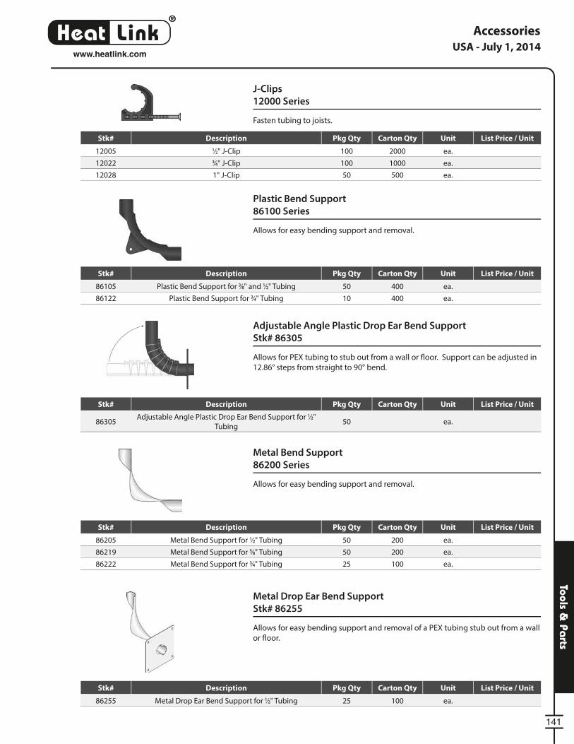
®
LinkHeat
141
Tools & Pa
rts
Plastic Bend Support
86100 Series
Allows for easy bending support and removal.
Metal Bend Support
86200 Series
Allows for easy bending support and removal.
J-Clips
12000 Series
Fasten tubing to joists.
Accessories
Adjustable Angle Plastic Drop Ear Bend Support
Stk# 86305
Allows for PEX tubing to stub out from a wall or fl oor. Support can be adjusted in
12.86° steps from straight to 90° bend.
Metal Drop Ear Bend Support
Stk# 86255
Allows for easy bending support and removal of a PEX tubing stub out from a wall
or fl oor.
USA - July 1, 2014www.heatlink.com
Stk# Description Pkg Qty Carton Qty Unit List Price / Unit
86105 Plastic Bend Support for 3⁄8" and 1⁄2" Tubing 50 400 ea.
86122 Plastic Bend Support for 3⁄4" Tubing 10 400 ea.
Stk# Description Pkg Qty Carton Qty Unit List Price / Unit
12005 1⁄2" J-Clip 100 2000 ea.
12022 3⁄4" J-Clip 100 1000 ea.
12028 1" J-Clip 50 500 ea.
Stk# Description Pkg Qty Carton Qty Unit List Price / Unit
86205 Metal Bend Support for 1⁄2" Tubing 50 200 ea.
86219 Metal Bend Support for 5⁄8" Tubing 50 200 ea.
86222 Metal Bend Support for 3⁄4" Tubing 25 100 ea.
Stk# Description Pkg Qty Carton Qty Unit List Price / Unit
86255 Metal Drop Ear Bend Support for 1⁄2" Tubing 25 100 ea.
Stk# Description Pkg Qty Carton Qty Unit List Price / Unit
86305Adjustable Angle Plastic Drop Ear Bend Support for 1⁄2"
Tubing50 ea.
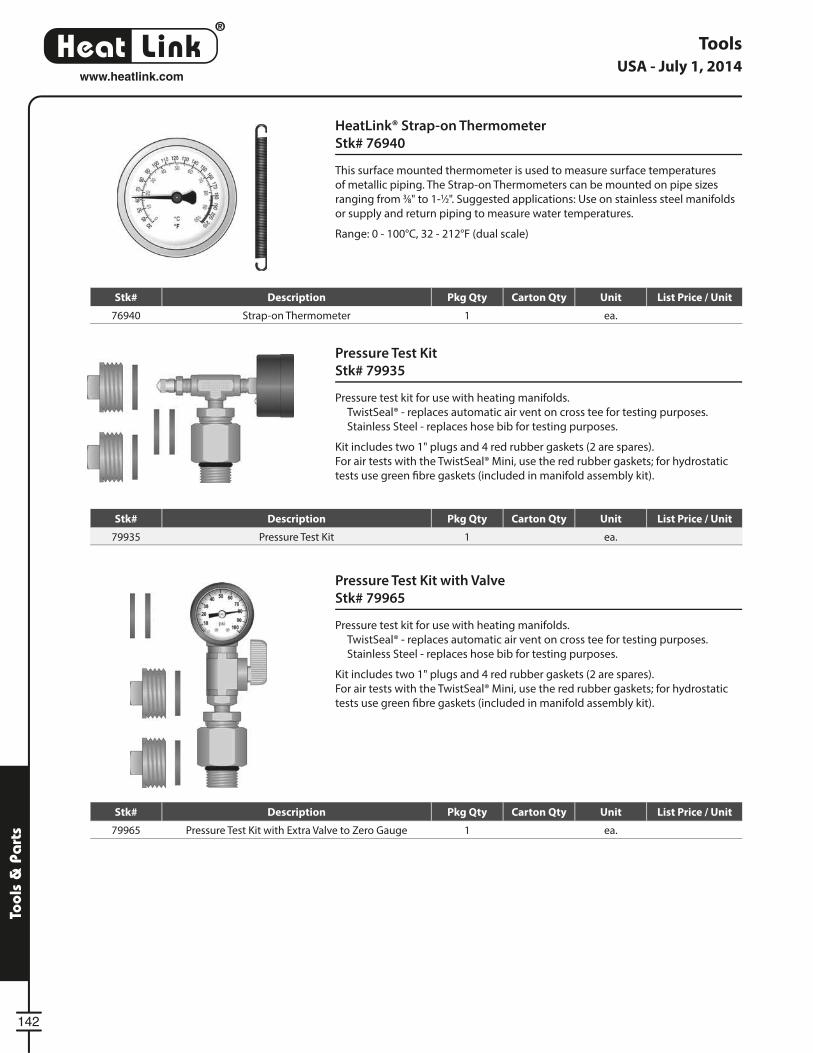
®
LinkHeat
142
Tool
s &
Pa
rts
Pressure Test Kit
Stk# 79935
Pressure test kit for use with heating manifolds.
TwistSeal® - replaces automatic air vent on cross tee for testing purposes.
Stainless Steel - replaces hose bib for testing purposes.
Kit includes two 1" plugs and 4 red rubber gaskets (2 are spares).
For air tests with the TwistSeal® Mini, use the red rubber gaskets; for hydrostatic
tests use green fi bre gaskets (included in manifold assembly kit).
Pressure Test Kit with Valve
Stk# 79965
Pressure test kit for use with heating manifolds.
TwistSeal® - replaces automatic air vent on cross tee for testing purposes.
Stainless Steel - replaces hose bib for testing purposes.
Kit includes two 1" plugs and 4 red rubber gaskets (2 are spares).
For air tests with the TwistSeal® Mini, use the red rubber gaskets; for hydrostatic
tests use green fi bre gaskets (included in manifold assembly kit).
HeatLink® Strap-on Thermometer
Stk# 76940
This surface mounted thermometer is used to measure surface temperatures
of metallic piping. The Strap-on Thermometers can be mounted on pipe sizes
ranging from 3⁄8" to 1-1⁄2". Suggested applications: Use on stainless steel manifolds
or supply and return piping to measure water temperatures.
Range: 0 - 100°C, 32 - 212°F (dual scale)
ToolsUSA - July 1, 2014
www.heatlink.com
Stk# Description Pkg Qty Carton Qty Unit List Price / Unit
76940 Strap-on Thermometer 1 ea.
Stk# Description Pkg Qty Carton Qty Unit List Price / Unit
79935 Pressure Test Kit 1 ea.
Stk# Description Pkg Qty Carton Qty Unit List Price / Unit
79965 Pressure Test Kit with Extra Valve to Zero Gauge 1 ea.
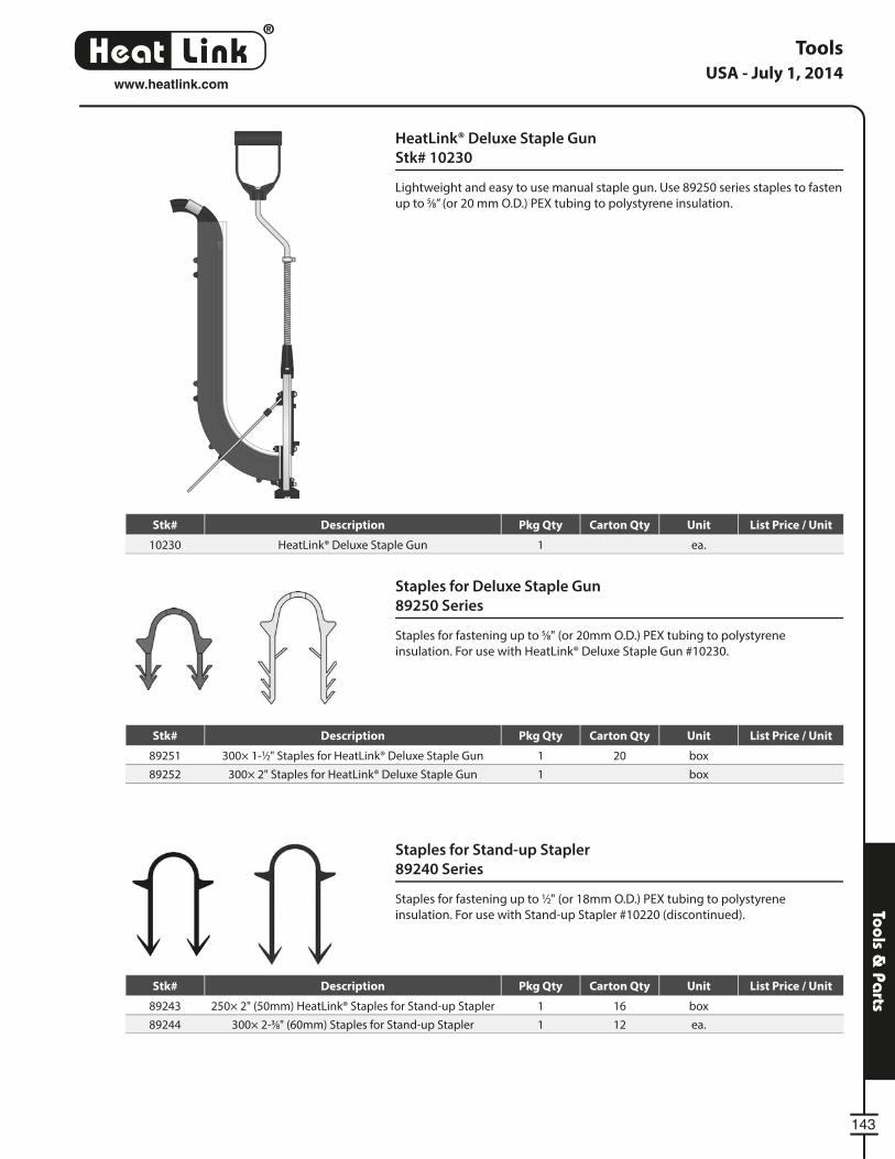
®
LinkHeat
143
Tools & Pa
rts
HeatLink® Deluxe Staple Gun
Stk# 10230
Lightweight and easy to use manual staple gun. Use 89250 series staples to fasten
up to 5⁄8” (or 20 mm O.D.) PEX tubing to polystyrene insulation.
Tools
Staples for Stand-up Stapler
89240 Series
Staples for fastening up to 1⁄2" (or 18mm O.D.) PEX tubing to polystyrene
insulation. For use with Stand-up Stapler #10220 (discontinued).
Staples for Deluxe Staple Gun
89250 Series
Staples for fastening up to 5⁄8" (or 20mm O.D.) PEX tubing to polystyrene
insulation. For use with HeatLink® Deluxe Staple Gun #10230.
USA - July 1, 2014www.heatlink.com
Stk# Description Pkg Qty Carton Qty Unit List Price / Unit
10230 HeatLink® Deluxe Staple Gun 1 ea.
Stk# Description Pkg Qty Carton Qty Unit List Price / Unit
89251 300× 1-1⁄2" Staples for HeatLink® Deluxe Staple Gun 1 20 box
89252 300× 2" Staples for HeatLink® Deluxe Staple Gun 1 box
Stk# Description Pkg Qty Carton Qty Unit List Price / Unit
89243 250× 2" (50mm) HeatLink® Staples for Stand-up Stapler 1 16 box
89244 300× 2-3⁄8" (60mm) Staples for Stand-up Stapler 1 12 ea.
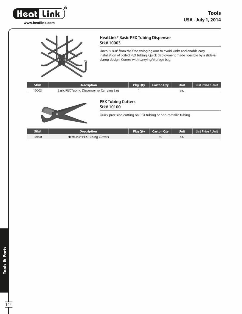
®
LinkHeat
144
Tool
s &
Pa
rts
Tools
PEX Tubing Cutters
Stk# 10100
Quick precision cutting on PEX tubing or non-metallic tubing.
HeatLink® Basic PEX Tubing Dispenser
Stk# 10003
Uncoils 360° from the free swinging arm to avoid kinks and enable easy
installation of coiled PEX tubing. Quick deployment made possible by a slide &
clamp design. Comes with carrying/storage bag.
USA - July 1, 2014www.heatlink.com
Stk# Description Pkg Qty Carton Qty Unit List Price / Unit
10003 Basic PEX Tubing Dispenser w/ Carrying Bag 1 ea.
Stk# Description Pkg Qty Carton Qty Unit List Price / Unit
10100 HeatLink® PEX Tubing Cutters 1 50 ea.
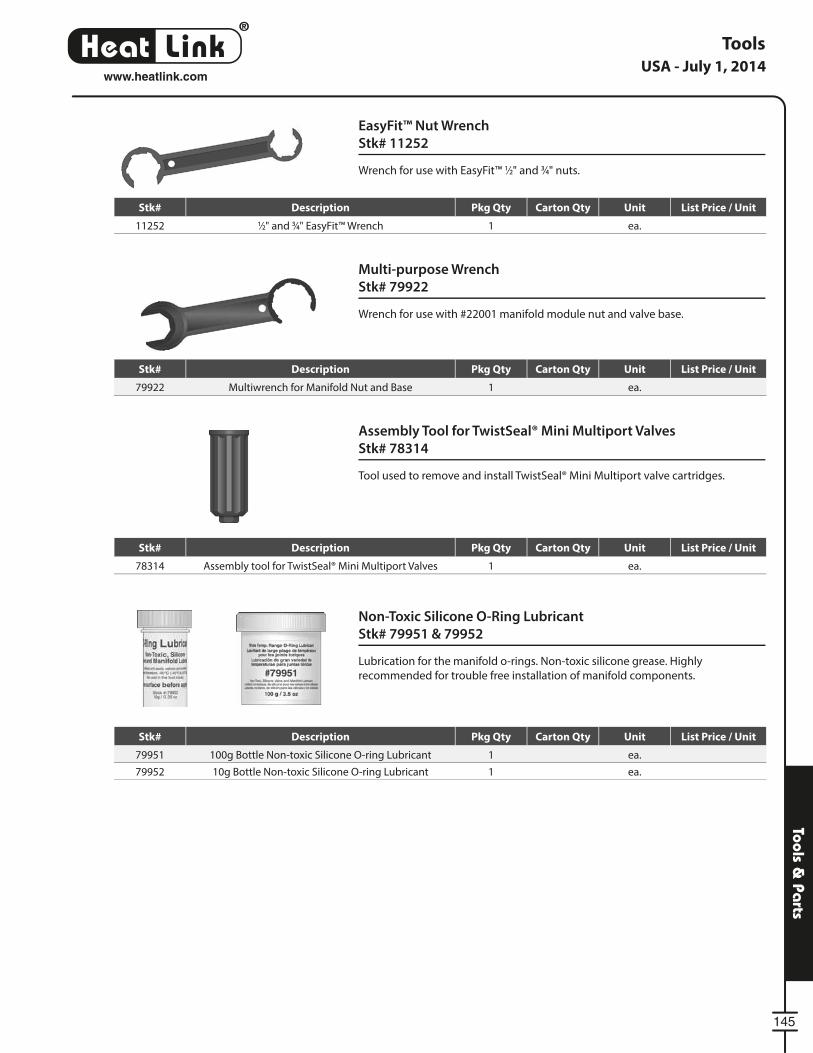
®
LinkHeat
145
Tools & Pa
rts
Multi-purpose Wrench
Stk# 79922
Wrench for use with #22001 manifold module nut and valve base.
Non-Toxic Silicone O-Ring Lubricant
Stk# 79951 & 79952
Lubrication for the manifold o-rings. Non-toxic silicone grease. Highly
recommended for trouble free installation of manifold components.
EasyFit™ Nut Wrench
Stk# 11252
Wrench for use with EasyFit™ 1⁄2" and 3⁄4" nuts.
Tools
Assembly Tool for TwistSeal® Mini Multiport Valves
Stk# 78314
Tool used to remove and install TwistSeal® Mini Multiport valve cartridges.
USA - July 1, 2014www.heatlink.com
Stk# Description Pkg Qty Carton Qty Unit List Price / Unit
11252 1⁄2" and 3⁄4" EasyFit™ Wrench 1 ea.
Stk# Description Pkg Qty Carton Qty Unit List Price / Unit
79922 Multiwrench for Manifold Nut and Base 1 ea.
Stk# Description Pkg Qty Carton Qty Unit List Price / Unit
79951 100g Bottle Non-toxic Silicone O-ring Lubricant 1 ea.
79952 10g Bottle Non-toxic Silicone O-ring Lubricant 1 ea.
Stk# Description Pkg Qty Carton Qty Unit List Price / Unit
78314 Assembly tool for TwistSeal® Mini Multiport Valves 1 ea.
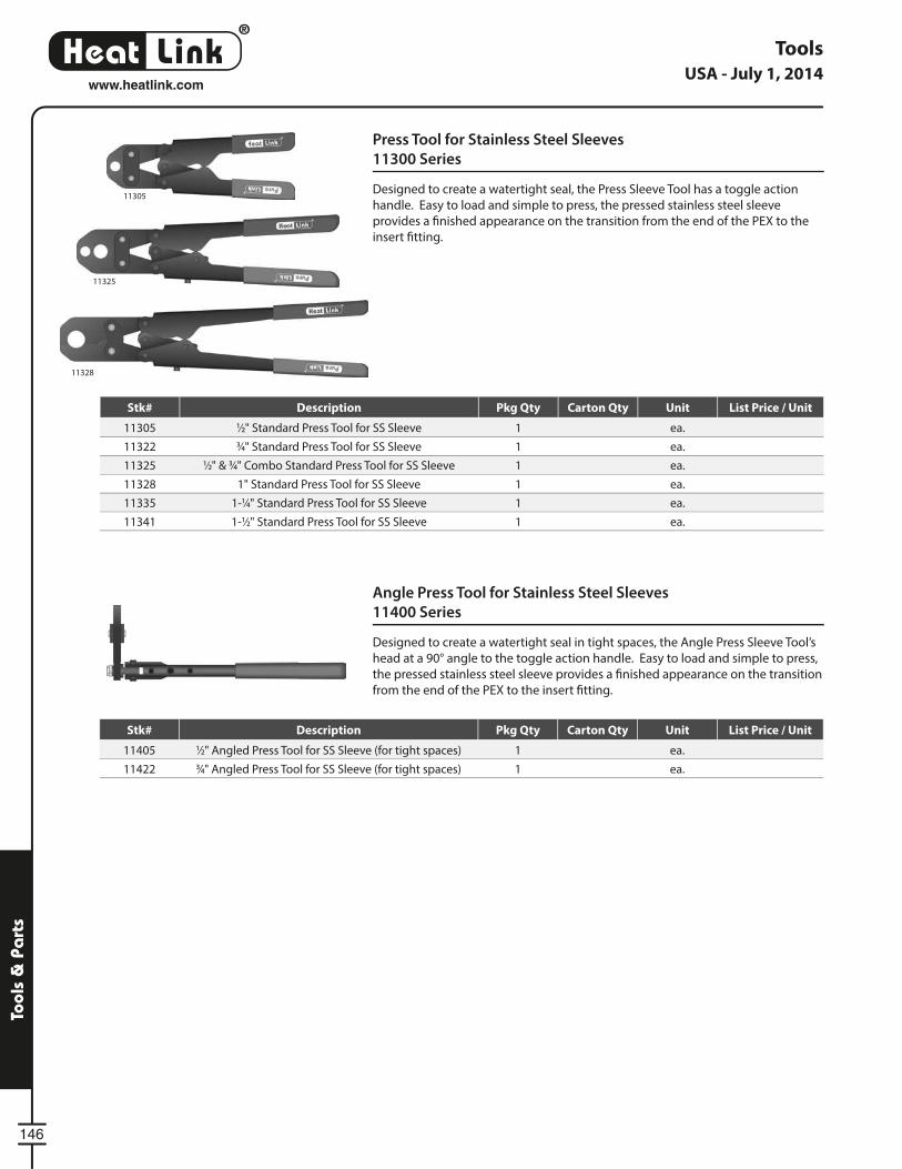
®
LinkHeat
146
Tool
s &
Pa
rts
Press Tool for Stainless Steel Sleeves
11300 Series
Designed to create a watertight seal, the Press Sleeve Tool has a toggle action
handle. Easy to load and simple to press, the pressed stainless steel sleeve
provides a fi nished appearance on the transition from the end of the PEX to the
insert fi tting.
Angle Press Tool for Stainless Steel Sleeves
11400 Series
Designed to create a watertight seal in tight spaces, the Angle Press Sleeve Tool’s
head at a 90° angle to the toggle action handle. Easy to load and simple to press,
the pressed stainless steel sleeve provides a fi nished appearance on the transition
from the end of the PEX to the insert fi tting.
Tools
11305
11325
11328
USA - July 1, 2014www.heatlink.com
Stk# Description Pkg Qty Carton Qty Unit List Price / Unit
11305 1⁄2" Standard Press Tool for SS Sleeve 1 ea.
11322 3⁄4" Standard Press Tool for SS Sleeve 1 ea.
11325 1⁄2" & 3⁄4" Combo Standard Press Tool for SS Sleeve 1 ea.
11328 1" Standard Press Tool for SS Sleeve 1 ea.
11335 1-1⁄4" Standard Press Tool for SS Sleeve 1 ea.
11341 1-1⁄2" Standard Press Tool for SS Sleeve 1 ea.
Stk# Description Pkg Qty Carton Qty Unit List Price / Unit
11405 1⁄2" Angled Press Tool for SS Sleeve (for tight spaces) 1 ea.
11422 3⁄4" Angled Press Tool for SS Sleeve (for tight spaces) 1 ea.
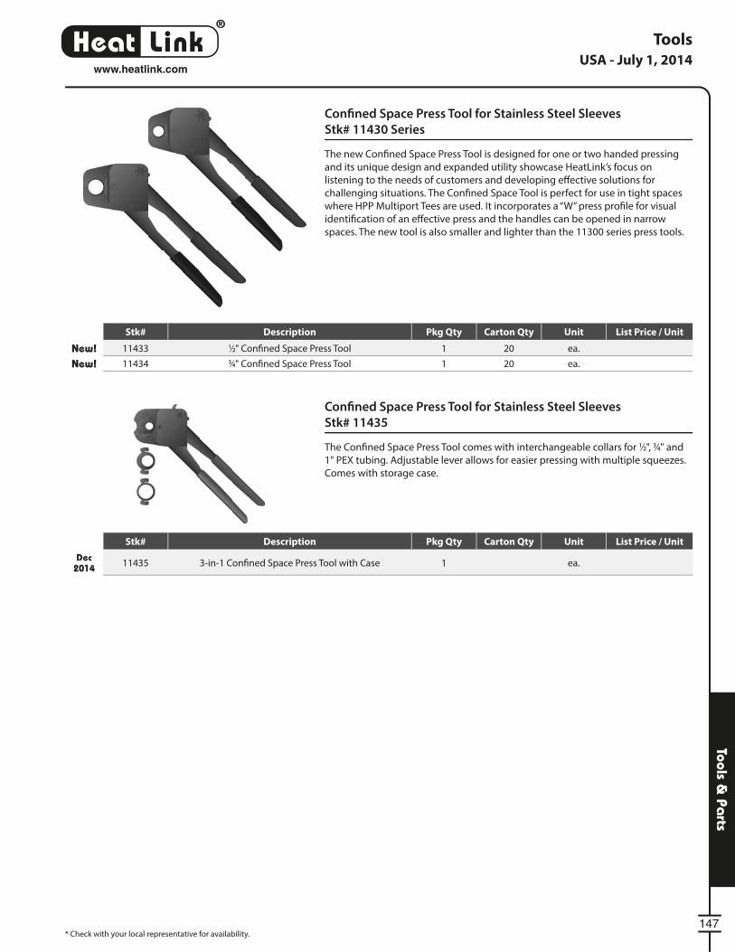
®
LinkHeat
147
Tools & Pa
rts
Confi ned Space Press Tool for Stainless Steel Sleeves
Stk# 11435
The Confi ned Space Press Tool comes with interchangeable collars for 1⁄2", 3⁄4" and
1" PEX tubing. Adjustable lever allows for easier pressing with multiple squeezes.
Comes with storage case.
Tools
* Check with your local representative for availability.
Confi ned Space Press Tool for Stainless Steel Sleeves
Stk# 11430 Series
The new Confi ned Space Press Tool is designed for one or two handed pressing
and its unique design and expanded utility showcase HeatLink’s focus on
listening to the needs of customers and developing eff ective solutions for
challenging situations. The Confi ned Space Tool is perfect for use in tight spaces
where HPP Multiport Tees are used. It incorporates a “W” press profi le for visual
identifi cation of an eff ective press and the handles can be opened in narrow
spaces. The new tool is also smaller and lighter than the 11300 series press tools.
USA - July 1, 2014www.heatlink.com
Stk# Description Pkg Qty Carton Qty Unit List Price / Unit
New! 11433 1⁄2" Confi ned Space Press Tool 1 20 ea.
New! 11434 3⁄4" Confi ned Space Press Tool 1 20 ea.
Stk# Description Pkg Qty Carton Qty Unit List Price / Unit
Dec 2014 11435 3-in-1 Confi ned Space Press Tool with Case 1 ea.
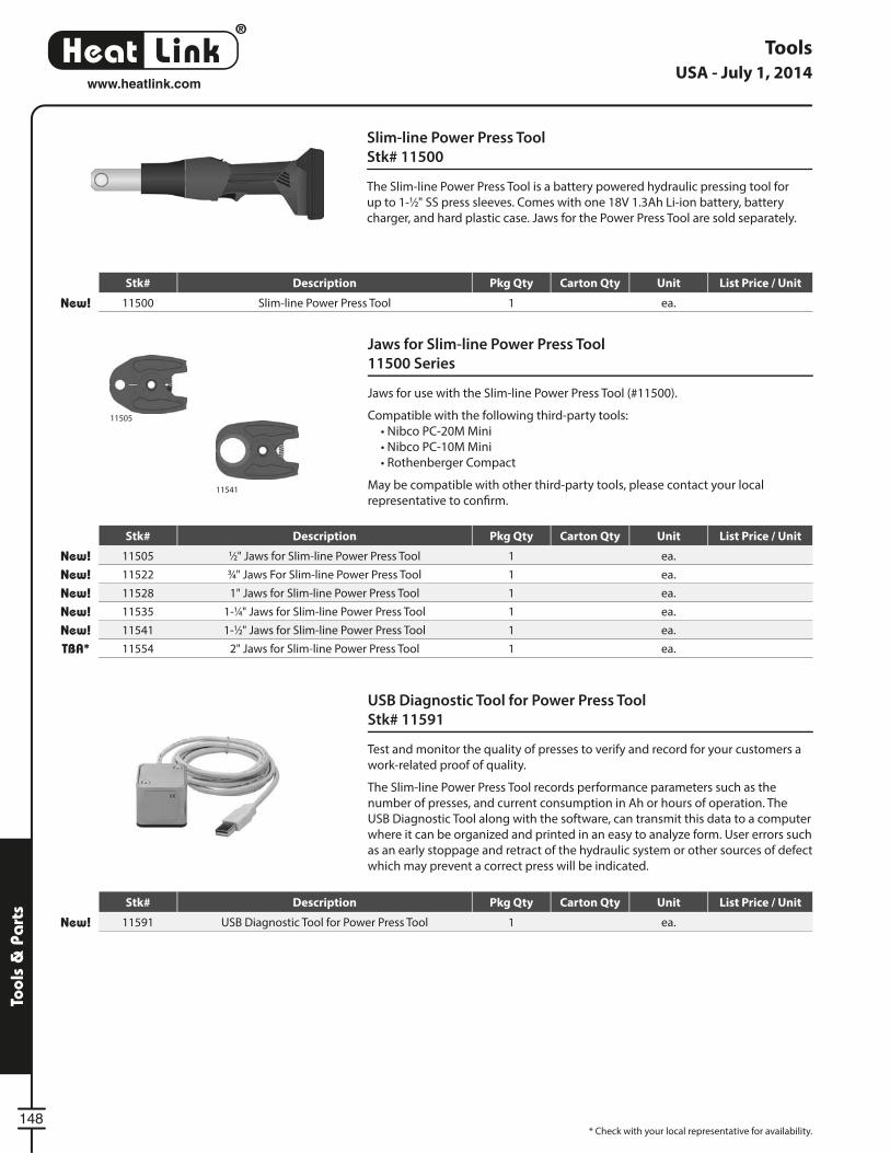
®
LinkHeat
148
Tool
s &
Pa
rts
Tools
Jaws for Slim-line Power Press Tool
11500 Series
Jaws for use with the Slim-line Power Press Tool (#11500).
Compatible with the following third-party tools:
• Nibco PC-20M Mini
• Nibco PC-10M Mini
• Rothenberger Compact
May be compatible with other third-party tools, please contact your local
representative to confi rm.
USB Diagnostic Tool for Power Press Tool
Stk# 11591
Test and monitor the quality of presses to verify and record for your customers a
work-related proof of quality.
The Slim-line Power Press Tool records performance parameters such as the
number of presses, and current consumption in Ah or hours of operation. The
USB Diagnostic Tool along with the software, can transmit this data to a computer
where it can be organized and printed in an easy to analyze form. User errors such
as an early stoppage and retract of the hydraulic system or other sources of defect
which may prevent a correct press will be indicated.
Slim-line Power Press Tool
Stk# 11500
The Slim-line Power Press Tool is a battery powered hydraulic pressing tool for
up to 1-1⁄2" SS press sleeves. Comes with one 18V 1.3Ah Li-ion battery, battery
charger, and hard plastic case. Jaws for the Power Press Tool are sold separately.
11505
11541
* Check with your local representative for availability.
USA - July 1, 2014www.heatlink.com
Stk# Description Pkg Qty Carton Qty Unit List Price / Unit
New! 11505 1⁄2" Jaws for Slim-line Power Press Tool 1 ea.
New! 11522 3⁄4" Jaws For Slim-line Power Press Tool 1 ea.
New! 11528 1" Jaws for Slim-line Power Press Tool 1 ea.
New! 11535 1-1⁄4" Jaws for Slim-line Power Press Tool 1 ea.
New! 11541 1-1⁄2" Jaws for Slim-line Power Press Tool 1 ea.
TBA* 11554 2" Jaws for Slim-line Power Press Tool 1 ea.
Stk# Description Pkg Qty Carton Qty Unit List Price / Unit
New! 11500 Slim-line Power Press Tool 1 ea.
Stk# Description Pkg Qty Carton Qty Unit List Price / Unit
New! 11591 USB Diagnostic Tool for Power Press Tool 1 ea.
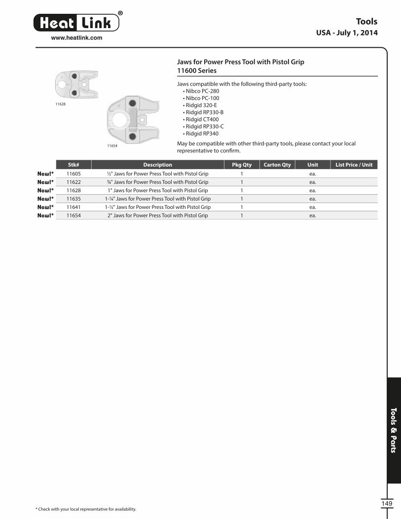
®
LinkHeat
149
Tools & Pa
rts
Jaws for Power Press Tool with Pistol Grip
11600 Series
Jaws compatible with the following third-party tools:
• Nibco PC-280
• Nibco PC-100
• Ridgid 320-E
• Ridgid RP330-B
• Ridgid CT400
• Ridgid RP330-C
• Ridgid RP340
May be compatible with other third-party tools, please contact your local
representative to confi rm.11654
11628
Tools
* Check with your local representative for availability.
USA - July 1, 2014www.heatlink.com
Stk# Description Pkg Qty Carton Qty Unit List Price / Unit
New!* 11605 1⁄2" Jaws for Power Press Tool with Pistol Grip 1 ea.
New!* 11622 3⁄4" Jaws for Power Press Tool with Pistol Grip 1 ea.
New!* 11628 1" Jaws for Power Press Tool with Pistol Grip 1 ea.
New!* 11635 1-1⁄4" Jaws for Power Press Tool with Pistol Grip 1 ea.
New!* 11641 1-1⁄2" Jaws for Power Press Tool with Pistol Grip 1 ea.
New!* 11654 2" Jaws for Power Press Tool with Pistol Grip 1 ea.
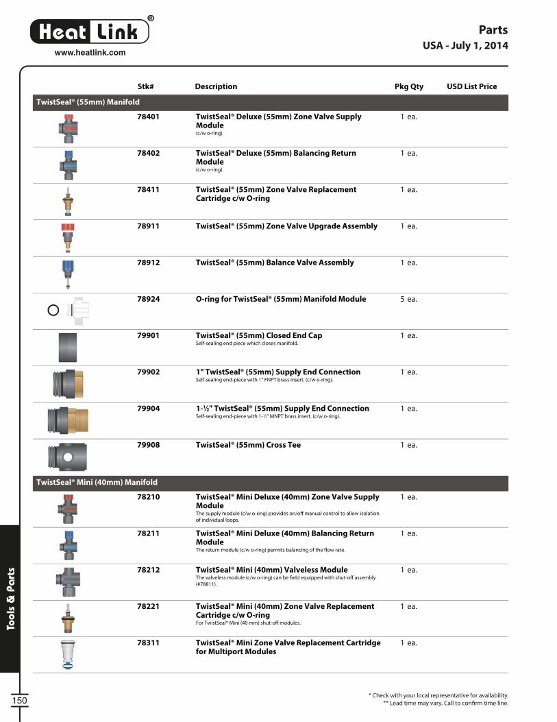
®
LinkHeat
150
Tool
s &
Pa
rts
* Check with your local representative for availability.
** Lead time may vary. Call to confi rm time line.
PartsUSA - July 1, 2014
www.heatlink.com
Stk# Description Pkg Qty USD List Price
TwistSeal® (55mm) Manifold
78401 ea.1TwistSeal® Deluxe (55mm) Zone Valve SupplyModule(c/w o-ring)
78402 ea.1TwistSeal® Deluxe (55mm) Balancing ReturnModule(c/w o-ring)
78411 ea.1TwistSeal® (55mm) Zone Valve ReplacementCartridge c/w O-ring
78911 ea.1TwistSeal® (55mm) Zone Valve Upgrade Assembly
78912 ea.1TwistSeal® (55mm) Balance Valve Assembly
78924 ea.5O-ring for TwistSeal® (55mm) Manifold Module
79901 ea.1TwistSeal® (55mm) Closed End CapSelf-sealing end piece which closes manifold.
79902 ea.11" TwistSeal® (55mm) Supply End ConnectionSelf-sealing end-piece with 1" FNPT brass insert. (c/w o-ring).
79904 ea.11-1⁄2" TwistSeal® (55mm) Supply End ConnectionSelf-sealing end-piece with 1-1⁄2" MNPT brass insert. (c/w o-ring).
79908 ea.1TwistSeal® (55mm) Cross Tee
TwistSeal® Mini (40mm) Manifold
78210 ea.1TwistSeal® Mini Deluxe (40mm) Zone Valve SupplyModuleThe supply module (c/w o-ring) provides on/o manual control to allow isolation
of individual loops.
78211 ea.1TwistSeal® Mini Deluxe (40mm) Balancing ReturnModuleThe return module (c/w o-ring) permits balancing of the ow rate.
78212 ea.1TwistSeal® Mini (40mm) Valveless ModuleThe valveless module (c/w o-ring) can be eld equipped with shut-o assembly
(#78811).
78221 ea.1TwistSeal® Mini (40mm) Zone Valve ReplacementCartridge c/w O-ringFor TwistSeal® Mini (40 mm) shut-o modules.
78311 ea.1TwistSeal® Mini Zone Valve Replacement Cartridgefor Multiport Modules
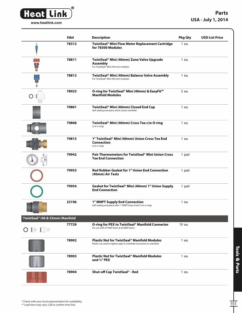
®
LinkHeat
151
Tools & Pa
rts
* Check with your local representative for availability.
** Lead time may vary. Call to confi rm time line.
PartsUSA - July 1, 2014
www.heatlink.com
Stk# Description Pkg Qty USD List Price
78312 ea.1TwistSeal® Mini Flow Meter Replacement Cartridgefor 78300 Modules
78811 ea.1TwistSeal® Mini (40mm) Zone Valve UpgradeAssemblyFor TwistSeal® Mini (40 mm) modules.
78812 ea.1TwistSeal® Mini (40mm) Balance Valve AssemblyFor TwistSeal® Mini (40 mm) modules.
78923 ea.5O-ring for TwistSeal® Mini (40mm) & EasyFit™Manifold Modules
79801 ea.1TwistSeal® Mini (40mm) Closed End CapSelf-sealing end-piece which closes manifold.
79808 ea.1TwistSeal® Mini (40mm) Cross Tee c/w O-ring(c/w o-ring)
79815 ea.11" TwistSeal® Mini (40mm) Union Cross Tee EndConnection(c/w o-ring)
79942 pair1Pair Thermometers for TwistSeal® Mini Union CrossTee End Connection
79953 pair1Red Rubber Gasket for 1" Union End Connection(40mm) Air Tests
79954 pair1Gasket for TwistSeal® Mini (40mm) 1" Union SupplyEnd Connection
22196 ea.11" MNPT Supply End ConnectionSelf-sealing end-piece with 1" MNPT brass insert (c/w o-ring).
TwistSeal® (40 & 55mm) Manifold
77729 ea.10O-ring for PEX to TwistSeal® Manifold ConnecterFor use with #77000 Series & #23000 Series.
78902 ea.1Plastic Nut for TwistSeal® Manifold ModulesPlastic nut used to tighten pipe to manifold connectors to manifold.
78903 ea.1Plastic Nut for TwistSeal® Manifold Modulesand 3⁄4" PEX
78904 ea.1Shut-o Cap TwistSeal® - Red
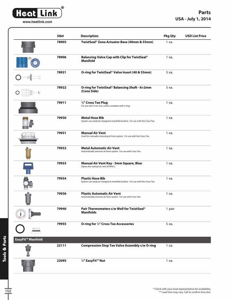
®
LinkHeat
152
Tool
s &
Pa
rts
* Check with your local representative for availability.
** Lead time may vary. Call to confi rm time line.
PartsUSA - July 1, 2014
www.heatlink.com
Stk# Description Pkg Qty USD List Price
78905 ea.1TwistSeal® Zone Actuator Base (40mm & 55mm)
78906 ea.1Balancing Valve Cap with Clip for TwistSeal®Manifold
78921 ea.5O-ring for TwistSeal® Valve Insert (40 & 55mm)
78922 ea.5O-ring for TwistSeal® Balancing Shaft - 6×2mm(Cone Side)
79911 ea.11⁄2" Cross Tee PlugFor use with Cross Tee, comes complete with o-ring.
79930 ea.1Metal Hose BibSystem can easily be charged at manifold location. For use with the Cross Tee.
79931 ea.1Manual Air VentUsed for manually removing air from system. For use with the Cross Tee.
79932 ea.1Metal Automatic Air VentAutomatically removes air from system. For use with Cross Tee.
79933 ea.1Manual Air Vent Key - 5mm Square, BlueOpens the manual air vent (#79931).
79934 ea.1Plastic Hose BibSystem can easily be charged at manifold location. For use with the Cross Tee.
79936 ea.1Plastic Automatic Air VentAutomatically removes air from system. For use with Cross Tee.
79940 pair1Pair Thermometers c/w Well for TwistSeal®Manifolds
79955 ea.5O-ring for 1⁄2" Cross Tee Accessories
EasyFit™ Manifold
22111 ea.1Compression Stop Tee Valve Assembly c/w O-ring
22095 ea.11⁄2" EasyFit™ Nut
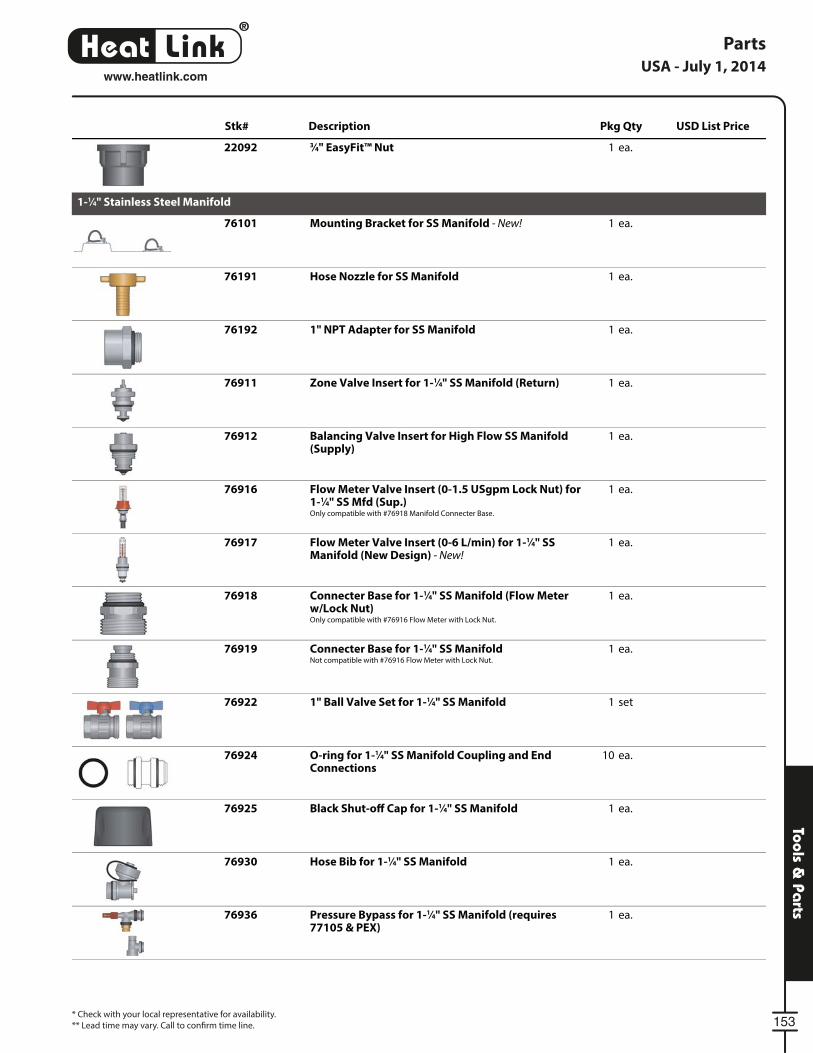
®
LinkHeat
153
Tools & Pa
rts
* Check with your local representative for availability.
** Lead time may vary. Call to confi rm time line.
PartsUSA - July 1, 2014
www.heatlink.com
Stk# Description Pkg Qty USD List Price
22092 ea.13⁄4" EasyFit™ Nut
1-1⁄4" Stainless Steel Manifold
76101 ea.1Mounting Bracket for SS Manifold - New!
76191 ea.1Hose Nozzle for SS Manifold
76192 ea.11" NPT Adapter for SS Manifold
76911 ea.1Zone Valve Insert for 1-1⁄4" SS Manifold (Return)
76912 ea.1Balancing Valve Insert for High Flow SS Manifold(Supply)
76916 ea.1Flow Meter Valve Insert (0-1.5 USgpm Lock Nut) for1-1⁄4" SS Mfd (Sup.)Only compatible with #76918 Manifold Connecter Base.
76917 ea.1Flow Meter Valve Insert (0-6 L/min) for 1-1⁄4" SSManifold (New Design) - New!
76918 ea.1Connecter Base for 1-1⁄4" SS Manifold (Flow Meterw/Lock Nut)Only compatible with #76916 Flow Meter with Lock Nut.
76919 ea.1Connecter Base for 1-1⁄4" SS ManifoldNot compatible with #76916 Flow Meter with Lock Nut.
76922 set11" Ball Valve Set for 1-1⁄4" SS Manifold
76924 ea.10O-ring for 1-1⁄4" SS Manifold Coupling and EndConnections
76925 ea.1Black Shut-o Cap for 1-1⁄4" SS Manifold
76930 ea.1Hose Bib for 1-1⁄4" SS Manifold
76936 ea.1Pressure Bypass for 1-1⁄4" SS Manifold (requires77105 & PEX)
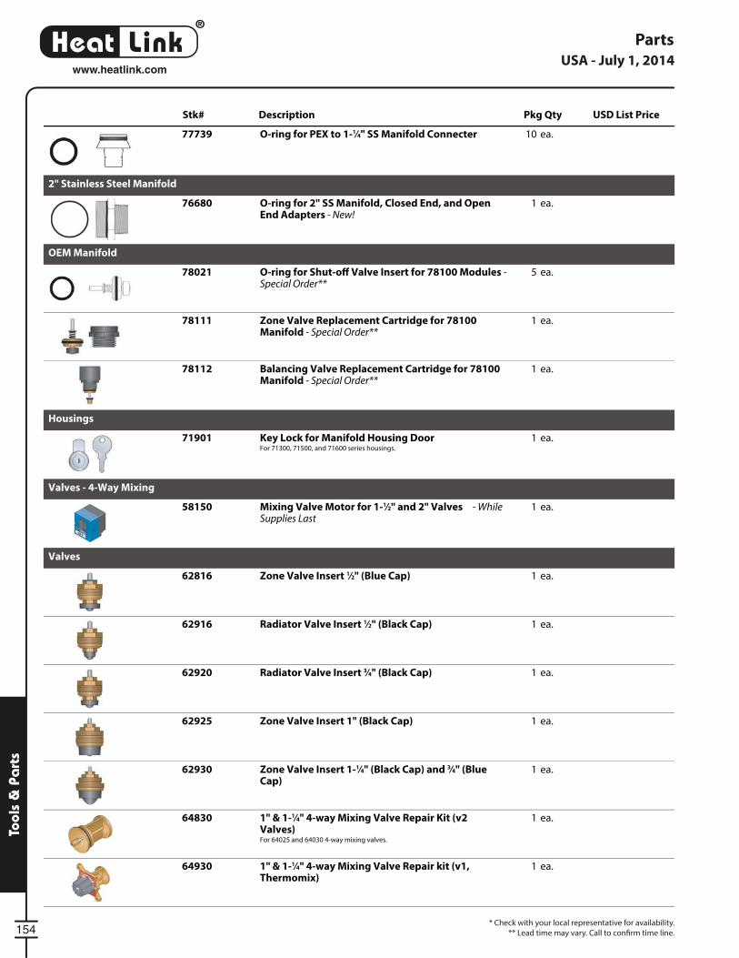
®
LinkHeat
154
Tool
s &
Pa
rts
* Check with your local representative for availability.
** Lead time may vary. Call to confi rm time line.
PartsUSA - July 1, 2014
www.heatlink.com
Stk# Description Pkg Qty USD List Price
77739 ea.10O-ring for PEX to 1-1⁄4" SS Manifold Connecter
2" Stainless Steel Manifold
76680 ea.1O-ring for 2" SS Manifold, Closed End, and OpenEnd Adapters - New!
OEM Manifold
78021 ea.5O-ring for Shut-o Valve Insert for 78100 Modules -Special Order**
78111 ea.1Zone Valve Replacement Cartridge for 78100Manifold - Special Order**
78112 ea.1Balancing Valve Replacement Cartridge for 78100Manifold - Special Order**
Housings
71901 ea.1Key Lock for Manifold Housing DoorFor 71300, 71500, and 71600 series housings.
Valves - 4-Way Mixing
58150 ea.1Mixing Valve Motor for 1-1⁄2" and 2" Valves - WhileSupplies Last
Valves
62816 ea.1Zone Valve Insert 1⁄2" (Blue Cap)
62916 ea.1Radiator Valve Insert 1⁄2" (Black Cap)
62920 ea.1Radiator Valve Insert 3⁄4" (Black Cap)
62925 ea.1Zone Valve Insert 1" (Black Cap)
62930 ea.1Zone Valve Insert 1-1⁄4" (Black Cap) and 3⁄4" (BlueCap)
64830 ea.11" & 1-1⁄4" 4-way Mixing Valve Repair Kit (v2Valves)For 64025 and 64030 4-way mixing valves.
64930 ea.11" & 1-1⁄4" 4-way Mixing Valve Repair kit (v1,Thermomix)
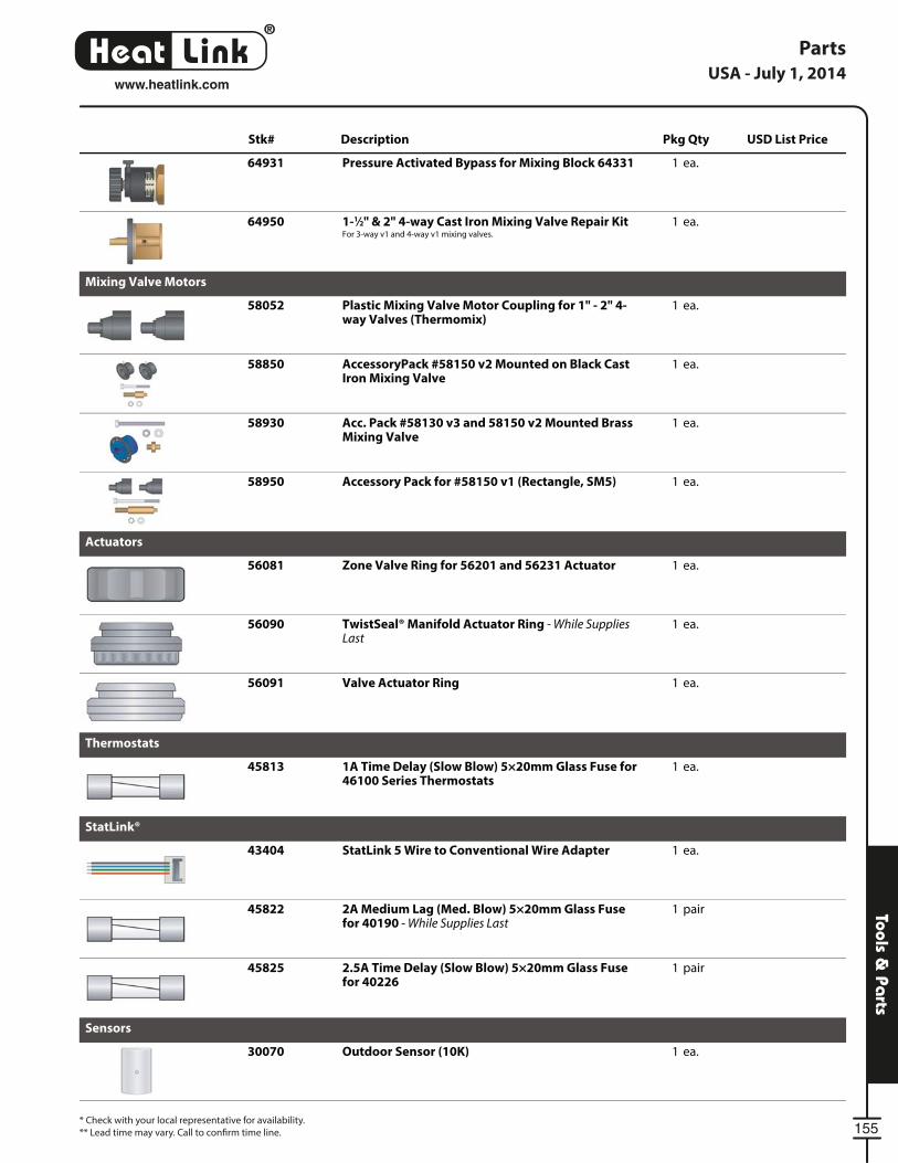
®
LinkHeat
155
Tools & Pa
rts
* Check with your local representative for availability.
** Lead time may vary. Call to confi rm time line.
PartsUSA - July 1, 2014
www.heatlink.com
Stk# Description Pkg Qty USD List Price
64931 ea.1Pressure Activated Bypass for Mixing Block 64331
64950 ea.11-1⁄2" & 2" 4-way Cast Iron Mixing Valve Repair KitFor 3-way v1 and 4-way v1 mixing valves.
Mixing Valve Motors
58052 ea.1Plastic Mixing Valve Motor Coupling for 1" - 2" 4-way Valves (Thermomix)
58850 ea.1AccessoryPack #58150 v2 Mounted on Black CastIron Mixing Valve
58930 ea.1Acc. Pack #58130 v3 and 58150 v2 Mounted BrassMixing Valve
58950 ea.1Accessory Pack for #58150 v1 (Rectangle, SM5)
Actuators
56081 ea.1Zone Valve Ring for 56201 and 56231 Actuator
56090 ea.1TwistSeal® Manifold Actuator Ring - While SuppliesLast
56091 ea.1Valve Actuator Ring
Thermostats
45813 ea.11A Time Delay (Slow Blow) 5×20mm Glass Fuse for46100 Series Thermostats
StatLink®
43404 ea.1StatLink 5 Wire to Conventional Wire Adapter
45822 pair12A Medium Lag (Med. Blow) 5×20mm Glass Fusefor 40190 - While Supplies Last
45825 pair12.5A Time Delay (Slow Blow) 5×20mm Glass Fusefor 40226
Sensors
30070 ea.1Outdoor Sensor (10K)
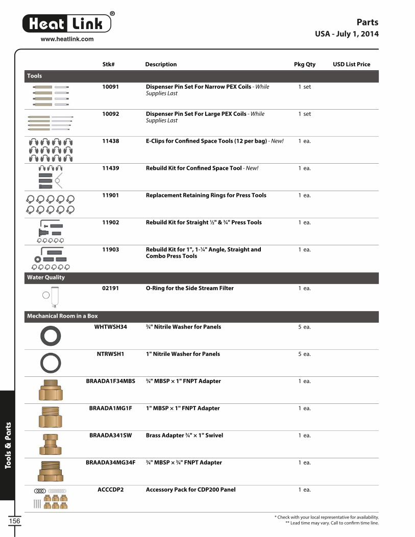
®
LinkHeat
156
Tool
s &
Pa
rts
* Check with your local representative for availability.
** Lead time may vary. Call to confi rm time line.
PartsUSA - July 1, 2014
www.heatlink.com
Stk# Description Pkg Qty USD List Price
Tools
10091 set1Dispenser Pin Set For Narrow PEX Coils - WhileSupplies Last
10092 set1Dispenser Pin Set For Large PEX Coils - WhileSupplies Last
11438 ea.1E-Clips for Con ned Space Tools (12 per bag) - New!
11439 ea.1Rebuild Kit for Con ned Space Tool - New!
11901 ea.1Replacement Retaining Rings for Press Tools
11902 ea.1Rebuild Kit for Straight 1⁄2" & 3⁄4" Press Tools
11903 ea.1Rebuild Kit for 1", 1-1⁄4" Angle, Straight andCombo Press Tools
Water Quality
02191 ea.1O-Ring for the Side Stream Filter
Mechanical Room in a Box
WHTWSH34 ea.53⁄4" Nitrile Washer for Panels
NTRWSH1 ea.51" Nitrile Washer for Panels
BRAADA1F34MBS ea.13⁄4" MBSP × 1" FNPT Adapter
BRAADA1MG1F ea.11" MBSP × 1" FNPT Adapter
BRAADA341SW ea.1Brass Adapter 3⁄4" × 1" Swivel
BRAADA34MG34F ea.13⁄4" MBSP × 3⁄4" FNPT Adapter
ACCCDP2 ea.1Accessory Pack for CDP200 Panel
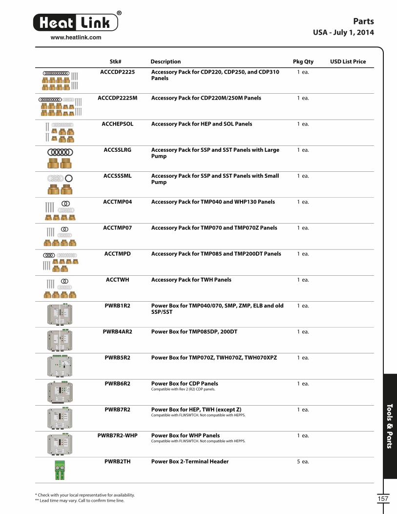
®
LinkHeat
157
Tools & Pa
rts
* Check with your local representative for availability.
** Lead time may vary. Call to confi rm time line.
PartsUSA - July 1, 2014
www.heatlink.com
Stk# Description Pkg Qty USD List Price
ACCCDP2225 ea.1Accessory Pack for CDP220, CDP250, and CDP310Panels
ACCCDP2225M ea.1Accessory Pack for CDP220M/250M Panels
ACCHEPSOL ea.1Accessory Pack for HEP and SOL Panels
ACCSSLRG ea.1Accessory Pack for SSP and SST Panels with LargePump
ACCSSSML ea.1Accessory Pack for SSP and SST Panels with SmallPump
ACCTMP04 ea.1Accessory Pack for TMP040 and WHP130 Panels
ACCTMP07 ea.1Accessory Pack for TMP070 and TMP070Z Panels
ACCTMPD ea.1Accessory Pack for TMP085 and TMP200DT Panels
ACCTWH ea.1Accessory Pack for TWH Panels
PWRB1R2 ea.1Power Box for TMP040/070, SMP, ZMP, ELB and oldSSP/SST
PWRB4AR2 ea.1Power Box for TMP085DP, 200DT
PWRB5R2 ea.1Power Box for TMP070Z, TWH070Z, TWH070XPZ
PWRB6R2 ea.1Power Box for CDP PanelsCompatible with Rev 2 (R2) CDP panels.
PWRB7R2 ea.1Power Box for HEP, TWH (except Z)Compatible with FLWSWTCH. Not compatible with HEPPS.
PWRB7R2-WHP ea.1Power Box for WHP PanelsCompatible with FLWSWTCH. Not compatible with HEPPS.
PWRB2TH ea.5Power Box 2-Terminal Header
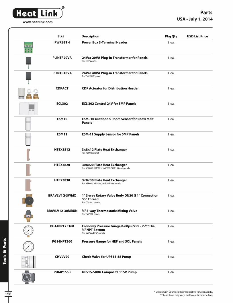
®
LinkHeat
158
Tool
s &
Pa
rts
* Check with your local representative for availability.
** Lead time may vary. Call to confi rm time line.
PartsUSA - July 1, 2014
www.heatlink.com
Stk# Description Pkg Qty USD List Price
PWRB3TH ea.5Power Box 3-Terminal Header
PLINTR20VA ea.124Vac 20VA Plug-In Transformer for PanelsFor CDP panels.
PLINTR40VA ea.124Vac 40VA Plug-in Transformer for PanelsFor TMP070Z panel.
CDPACT ea.1CDP Actuator for Distribution Header
ECL302 ea.1ECL 302 Control 24V for SMP Panels
ESM10 ea.1ESM -10 Outdoor & Room Sensor for Snow MeltPanels
ESM11 ea.1ESM-11 Supply Sensor for SMP Panels
HTEX3812 ea.13×8×12 Plate Heat ExchangerFor HEP025 panel.
HTEX3820 ea.13×8×20 Plate Heat ExchangerFor SOL080, SMP105, SMP250, SMP335 and panels.
HTEX3830 ea.13×8×30 Plate Heat ExchangerFor HEP080, HEP095, and SMP425 panels.
BRAVLV1G-3WMX ea.11" 3-way Rotary Valve Body DN20 G 1" Connection"G" ThreadFor CDP310 panels.
BRAVLV12-30MRUN ea.13⁄4" 3-way Thermostatic Mixing ValveFor TMP040 panel.
PG14NPT25160 ea.1Economy Pressure Guage 0-60psi/kPa - 2-1⁄2" Dial1⁄4" NPT BottomFor SMP and PSP panels.
PG14NPT260 ea.1Pressure Gauge for HEP and SOL Panels
CHVLV20 ea.1Check Valve for UPS15-58 Pump
PUMP1558 ea.1UPS15-58RU Composite 115V Pump
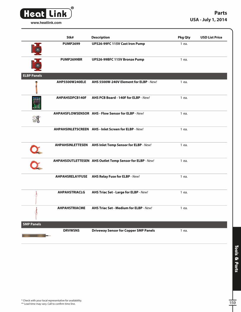
®
LinkHeat
159
Tools & Pa
rts
* Check with your local representative for availability.
** Lead time may vary. Call to confi rm time line.
PartsUSA - July 1, 2014
www.heatlink.com
Stk# Description Pkg Qty USD List Price
PUMP2699 ea.1UPS26-99FC 115V Cast Iron Pump
PUMP2699BR ea.1UPS26-99BFC 115V Bronze Pump
ELBP Panels
AHP5500W240ELE ea.1AHS 5500W-240V Element for ELBP - New!
AHPAHSDPCB140F ea.1AHS PCB Board - 140F for ELBP - New!
AHPAHSFLOWSENSOR ea.1AHS - Flow Sensor for ELBP - New!
AHPAHSINLETSCREEN ea.1AHS - Inlet Screen for ELBP - New!
AHPAHSINLETTESEN ea.1AHS Inlet Temp Sensor for ELBP - New!
AHPAHSOUTLETTESEN ea.1AHS Outlet Temp Sensor for ELBP - New!
AHPAHSRELAYFUSE ea.1AHS Relay Fuse for ELBP - New!
AHPAHSTRIACLG ea.1AHS Triac Set - Large for ELBP - New!
AHPAHSTRIACME ea.1AHS Triac Set - Medium for ELBP - New!
SMP Panels
DRVWSNS ea.1Driveway Sensor for Copper SMP Panels

®
LinkHeat
160
www.heatlink.com
Listing by Stk#
* C
he
ck w
ith
yo
ur
loca
l re
pre
sen
tati
ve f
or
ava
ilab
ility
.
** L
ea
d t
ime
may
va
ry. C
all
to c
on
fi rm
tim
e li
ne
.
USA - July 1, 2014S
tk#
De
scri
pti
on
Sta
tus
Lis
t P
rice
/ U
nit
Pg
.
00
41
2H
ea
tLin
k P
reve
nta
tive
Ma
inte
na
nce
Wat
er
An
aly
sis
(re
qu
ire
s w
sb2
)
57
01
02
0M
oly
bd
en
um
Te
st K
it5
7
01
20
51
L C
orr
osi
on
Inh
ibit
or
(Mo
lyb
da
te B
ase
d)
56
01
31
11
L P
urg
ing
Co
mp
ou
nd
(P
re &
Po
st
Op
era
tio
na
l Cle
an
er)
56
01
32
11
L P
ost
op
era
tio
na
l Filt
rati
on
Cle
an
er
56
02
12
51
" S
ide
Str
ea
m F
ilte
r5
8
02
19
1O
-Rin
g f
or
the
Sid
e S
tre
am
Filt
er
15
6
10
00
0D
elu
xe P
EX
Tu
bin
g D
isp
en
ser
Dis
con
tin
ue
d
10
00
3B
asi
c P
EX
Tu
bin
g D
isp
en
ser
w/
Ca
rryi
ng
Ba
g1
44
10
09
1D
isp
en
ser
Pin
Se
t Fo
r N
arr
ow
PE
X C
oils
WS
L1
56
10
09
2D
isp
en
ser
Pin
Se
t Fo
r La
rge
PE
X C
oils
WS
L1
56
10
10
0H
ea
tLin
k® P
EX
Tu
bin
g C
utt
ers
14
4
10
23
0H
ea
tLin
k® D
elu
xe S
tap
le G
un
14
3
11
25
21⁄2"
an
d 3
⁄4" E
asy
Fit™
Wre
nch
14
5
11
30
51⁄2"
Sta
nd
ard
Pre
ss T
oo
l fo
r S
S S
lee
ve1
46
11
32
23⁄4"
Sta
nd
ard
Pre
ss T
oo
l fo
r S
S S
lee
ve1
46
11
32
51⁄2"
& 3
⁄4" C
om
bo
Sta
nd
ard
Pre
ss T
oo
l fo
r S
S
Sle
eve
14
6
11
32
81
" S
tan
da
rd P
ress
To
ol f
or
SS
Sle
eve
14
6
11
33
51
-1⁄4"
Sta
nd
ard
Pre
ss T
oo
l fo
r S
S S
lee
ve1
46
11
34
11
-1⁄2"
Sta
nd
ard
Pre
ss T
oo
l fo
r S
S S
lee
ve1
46
11
40
51⁄2"
An
gle
d P
ress
To
ol f
or
SS
Sle
eve
(fo
r ti
gh
t
spa
ces)
14
6
11
42
23⁄4"
An
gle
d P
ress
To
ol f
or
SS
Sle
eve
(fo
r ti
gh
t
spa
ces)
14
6
11
43
31⁄2"
Co
nfi
ne
d S
pa
ce P
ress
To
ol
Ne
w!
14
7
11
43
43⁄4"
Co
nfi
ne
d S
pa
ce P
ress
To
ol
Ne
w!
14
7
11
43
53
-in
-1 C
on
fi n
ed
Sp
ace
Pre
ss T
oo
l wit
h C
ase
Ne
w!*
14
7
11
43
8E
-Clip
s fo
r C
on
fi n
ed
Sp
ace
To
ols
(1
2 p
er
ba
g)
Ne
w!
15
6
11
43
9R
eb
uild
Kit
fo
r C
on
fi n
ed
Sp
ace
To
ol
Ne
w!
15
6
11
50
0S
lim-l
ine
Po
we
r P
ress
To
ol
Ne
w!
14
8
11
50
51⁄2"
Jaw
s fo
r S
lim-l
ine
Po
we
r P
ress
To
ol
Ne
w!
14
8
11
52
23⁄4"
Jaw
s Fo
r S
lim-l
ine
Po
we
r P
ress
To
ol
Ne
w!
14
8
11
52
81
" Ja
ws
for
Slim
-lin
e P
ow
er
Pre
ss T
oo
lN
ew
!1
48
11
53
51
-1⁄4"
Jaw
s fo
r S
lim-l
ine
Po
we
r P
ress
To
ol
Ne
w!
14
8
11
54
11
-1⁄2"
Jaw
s fo
r S
lim-l
ine
Po
we
r P
ress
To
ol
Ne
w!
14
8
11
55
42
" Ja
ws
for
Slim
-lin
e P
ow
er
Pre
ss T
oo
lT
BA
*1
48
11
59
1U
SB
Dia
gn
ost
ic T
oo
l fo
r P
ow
er
Pre
ss T
oo
lN
ew
!1
48
11
60
51⁄2"
Jaw
s fo
r P
ow
er
Pre
ss T
oo
l wit
h P
isto
l Gri
pN
ew
!*1
49
11
62
23⁄4"
Jaw
s fo
r P
ow
er
Pre
ss T
oo
l wit
h P
isto
l Gri
pN
ew
!*1
49
11
62
81
" Ja
ws
for
Po
we
r P
ress
To
ol w
ith
Pis
tol G
rip
Ne
w!*
14
9
11
63
51
-1⁄4"
Jaw
s fo
r P
ow
er
Pre
ss T
oo
l wit
h P
isto
l Gri
pN
ew
!*1
49
11
64
11
-1⁄2"
Jaw
s fo
r P
ow
er
Pre
ss T
oo
l wit
h P
isto
l Gri
pN
ew
!*1
49
11
65
42
" Ja
ws
for
Po
we
r P
ress
To
ol w
ith
Pis
tol G
rip
Ne
w!*
14
9
Stk
#D
esc
rip
tio
nS
tatu
sL
ist
Pri
ce /
Un
itP
g.
11
90
1R
ep
lace
me
nt
Re
tain
ing
Rin
gs
for
Pre
ss T
oo
ls1
56
11
90
2R
eb
uild
Kit
fo
r S
tra
igh
t 1⁄2"
& 3
⁄4" P
ress
To
ols
15
6
11
90
3R
eb
uild
Kit
fo
r 1
", 1
-1⁄4"
An
gle
, Str
aig
ht
an
d
Co
mb
o P
ress
To
ols
15
6
12
00
51⁄2"
J-C
lip1
41
12
02
23⁄4"
J-C
lip1
41
12
02
81
" J-
Clip
14
1
13
20
33
Po
rt S
ing
le R
ow
, 3⁄4"
PE
X ×
Clo
sed
En
d H
PP
Mu
ltip
ort
Te
e
12
5
13
20
44
Po
rt S
ing
le R
ow
, 3⁄4"
PE
X ×
Clo
sed
En
d H
PP
Mu
ltip
ort
Te
e
12
5
13
20
66
Po
rt S
ing
le R
ow
, 3⁄4"
PE
X ×
Clo
sed
En
d H
PP
Mu
ltip
ort
Te
e
12
5
13
20
88
Po
rt S
ing
le R
ow
, 3⁄4"
PE
X ×
Clo
sed
En
d H
PP
Mu
ltip
ort
Te
e
12
5
13
80
66
Po
rt S
ing
le R
ow
, 1"
PE
X ×
Clo
sed
En
d H
PP
Mu
ltip
ort
Te
e
12
5
13
80
88
Po
rt S
ing
le R
ow
, 1"
PE
X ×
Clo
sed
En
d H
PP
Mu
ltip
ort
Te
e
12
5
13
83
36
Po
rt O
pp
osi
ng
Ro
ws,
1"
PE
X ×
Clo
sed
En
d
HP
P M
ult
ipo
rt T
ee
12
5
13
84
48
Po
rt O
pp
osi
ng
Ro
ws,
1"
PE
X ×
Clo
sed
En
d
HP
P M
ult
ipo
rt T
ee
12
5
14
20
33
Po
rt S
ing
le R
ow
, 3⁄4"
PE
X ×
3⁄4"
PE
X F
low
Th
rou
gh
HP
P M
ult
ipo
rt T
ee
12
5
14
20
44
Po
rt S
ing
le R
ow
, 3⁄4"
PE
X ×
3⁄4"
PE
X F
low
Th
rou
gh
HP
P M
ult
ipo
rt T
ee
12
5
14
23
36
Po
rt O
pp
osi
ng
Ro
ws,
3⁄4"
PE
X ×
3⁄4"
PE
X F
low
Th
rou
gh
HP
P M
ult
ipo
rt T
ee
12
5
14
24
48
Po
rt O
pp
osi
ng
Ro
ws,
3⁄4"
PE
X ×
3⁄4"
PE
X F
low
Th
rou
gh
HP
P M
ult
ipo
rt T
ee
12
5
14
70
33
Po
rt S
ing
le R
ow
, 1"
PE
X ×
3⁄4"
PE
X F
low
Th
rou
gh
HP
P M
ult
ipo
rt T
ee
12
5
14
70
44
Po
rt S
ing
le R
ow
, 1"
PE
X ×
3⁄4"
PE
X F
low
Th
rou
gh
HP
P M
ult
ipo
rt T
ee
12
5
14
70
66
Po
rt S
ing
le R
ow
, 1"
PE
X ×
3⁄4"
PE
X F
low
Th
rou
gh
HP
P M
ult
ipo
rt T
ee
12
5
14
70
88
Po
rt S
ing
le R
ow
, 1"
PE
X ×
3⁄4"
PE
X F
low
Th
rou
gh
HP
P M
ult
ipo
rt T
ee
12
5
14
73
36
Po
rt O
pp
osi
ng
Ro
ws,
1"
PE
X ×
3⁄4"
PE
X F
low
Th
rou
gh
HP
P M
ult
ipo
rt T
ee
12
5
14
74
48
Po
rt O
pp
osi
ng
Ro
ws,
1"
PE
X ×
3⁄4"
PE
X F
low
Th
rou
gh
HP
P M
ult
ipo
rt T
ee
12
5
15
00
51⁄2"
PE
X H
PP
Plu
g1
37
15
02
23⁄4"
PE
X H
PP
Plu
g1
37
15
02
81
" P
EX
HP
P P
lug
13
7
16
22
23⁄4"
× 3
⁄4" ×
3⁄4"
PE
X H
PP
Te
e1
36
16
22
53⁄4"
× 3
⁄4" ×
1⁄2"
PE
X H
PP
Te
e1
36
16
22
83⁄4"
× 3
⁄4" ×
1"
PE
X H
PP
Te
e1
36
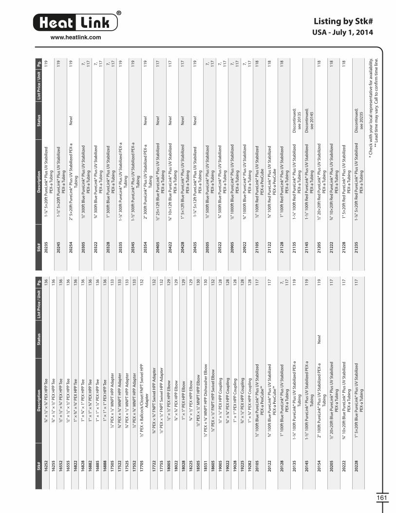
®
LinkHeat
161
www.heatlink.com
Listing by Stk#
* C
he
ck w
ith
yo
ur
loca
l re
pre
sen
tati
ve f
or
ava
ilab
ility
.
** L
ea
d t
ime
may
va
ry. C
all
to c
on
fi rm
tim
e li
ne
.
USA - July 1, 2014S
tk#
De
scri
pti
on
Sta
tus
Lis
t P
rice
/ U
nit
Pg
.
16
25
23⁄4"
× 1
⁄2" ×
3⁄4"
PE
X H
PP
Te
e1
36
16
25
53⁄4"
× 1
⁄2" ×
1⁄2"
PE
X H
PP
Te
e1
36
16
55
21⁄2"
× 1
⁄2" ×
3⁄4"
PE
X H
PP
Te
e1
36
16
55
51⁄2"
× 1
⁄2" ×
1⁄2"
PE
X H
PP
Te
e1
36
16
82
21
" ×
3⁄4"
× 3
⁄4" P
EX
HP
P T
ee
13
6
16
82
81
" ×
3⁄4"
× 1
" P
EX
HP
P T
ee
13
6
16
88
21
" ×
1"
× 3
⁄4" P
EX
HP
P T
ee
13
6
16
88
51
" ×
1"
× 1
⁄2" P
EX
HP
P T
ee
13
6
16
88
81
" ×
1"
× 1
" P
EX
HP
P T
ee
13
6
17
50
51⁄2"
PE
X ×
1⁄2"
MN
PT
HP
P A
da
pte
r1
33
17
52
23⁄4"
PE
X ×
3⁄4"
MN
PT
HP
P A
da
pte
r1
33
17
52
53⁄4"
PE
X ×
1⁄2"
MN
PT
HP
P A
da
pte
r1
33
17
55
21⁄2"
PE
X ×
3⁄4"
MN
PT
HP
P A
da
pte
r1
33
17
70
51⁄2"
PE
X ×
Ba
llco
ck/C
lose
t F
NP
T S
wiv
el H
PP
Ad
ap
ter
13
2
17
72
23⁄4"
PE
X ×
3⁄4"
FN
PT
Sw
ive
l HP
P A
da
pte
r1
32
17
75
51⁄2"
PE
X ×
1⁄2"
FN
PT
Sw
ive
l HP
P A
da
pte
r1
32
18
00
51⁄2"
× 1
⁄2" P
EX
HP
P E
lbo
w1
29
18
02
23⁄4"
× 3
⁄4" P
EX
HP
P E
lbo
w1
29
18
02
81
" ×
1"
PE
X H
PP
Elb
ow
12
9
18
22
53⁄4"
× 1
⁄2" P
EX
HP
P E
lbo
w1
29
18
50
51⁄2"
PE
X ×
1⁄2"
MN
PT
HP
P E
lbo
w1
30
18
55
11⁄2"
PE
X ×
3⁄8"
MN
PT
HP
P D
ish
wa
she
r E
lbo
w1
30
18
60
51⁄2"
PE
X ×
1⁄2"
FN
PT
HP
P S
wiv
el E
lbo
w1
32
19
00
51⁄2"
× 1
⁄2" P
EX
HP
P C
ou
plin
g1
28
19
02
23⁄4"
× 3
⁄4" P
EX
HP
P C
ou
plin
g1
28
19
02
81
" ×
1"
PE
X H
PP
Co
up
ling
12
8
19
22
53⁄4"
× 1
⁄2" P
EX
HP
P C
ou
plin
g1
28
19
28
21
" ×
3⁄4"
PE
X H
PP
Co
up
ling
12
8
20
10
51⁄2"
10
0ft
Blu
e P
ure
Lin
k® P
lus
UV
Sta
bili
zed
PE
X-a
Pe
xCu
be
™
11
7
20
12
23⁄4"
10
0ft
Blu
e P
ure
Lin
k® P
lus
UV
Sta
bili
zed
PE
X-a
Pe
xCu
be
™
11
7
20
12
81
" 1
00
ft B
lue
Pu
reLi
nk®
Plu
s U
V S
tab
ilize
d
PE
X-a
Tu
bin
g
7,
11
7
20
13
51
-1⁄4"
10
0ft
Pu
reLi
nk®
Plu
s U
V S
tab
ilize
d P
EX
-a
Tub
ing
11
9
20
14
51
-1⁄2"
10
0ft
Pu
reLi
nk®
Plu
s U
V S
tab
ilize
d P
EX
-a
Tub
ing
11
9
20
15
42
" 1
00
ft P
ure
Lin
k® P
lus
UV
Sta
bili
zed
PE
X-a
Tub
ing
Ne
w!
11
9
20
20
51⁄2"
20
×2
0ft
Blu
e P
ure
Lin
k® P
lus
UV
Sta
bili
zed
PE
X-a
Tu
bin
g
11
7
20
22
23⁄4"
10
×2
0ft
Blu
e P
ure
Lin
k® P
lus
UV
Sta
bili
zed
PE
X-a
Tu
bin
g
11
7
20
22
81
" 5
×2
0ft
Blu
e P
ure
Lin
k® P
lus
UV
Sta
bili
zed
PE
X-a
Tu
bin
g
11
7
Stk
#D
esc
rip
tio
nS
tatu
sL
ist
Pri
ce /
Un
itP
g.
20
23
51
-1⁄4"
5×
20
ft P
ure
Lin
k® P
lus
UV
Sta
bili
zed
PE
X-a
Tu
bin
g
11
9
20
24
51
-1⁄2"
5×
20
ft P
ure
Lin
k® P
lus
UV
Sta
bili
zed
PE
X-a
Tu
bin
g
11
9
20
25
42
" 5
×2
0ft
Pu
reLi
nk®
Plu
s U
V S
tab
ilize
d P
EX
-a
Tub
ing
Ne
w!
11
9
20
30
51⁄2"
30
0ft
Blu
e P
ure
Lin
k® P
lus
UV
Sta
bili
zed
PE
X-a
Tu
bin
g
7,
11
7
20
32
23⁄4"
30
0ft
Blu
e P
ure
Lin
k® P
lus
UV
Sta
bili
zed
PE
X-a
Tu
bin
g
7,
11
7
20
32
81
" 3
00
ft B
lue
Pu
reLi
nk®
Plu
s U
V S
tab
ilize
d
PE
X-a
Tu
bin
g
7,
11
7
20
33
51
-1⁄4"
30
0ft
Pu
reLi
nk®
Plu
s U
V S
tab
ilize
d P
EX
-a
Tub
ing
11
9
20
34
51
-1⁄2"
30
0ft
Pu
reLi
nk®
Plu
s U
V S
tab
ilize
d P
EX
-a
Tub
ing
11
9
20
35
42
" 3
00
ft P
ure
Lin
k® P
lus
UV
Sta
bili
zed
PE
X-a
Tub
ing
Ne
w!
11
9
20
40
51⁄2"
25
×1
2ft
Blu
e P
ure
Lin
k® P
lus
UV
Sta
bili
zed
PE
X-a
Tu
bin
g
Ne
w!
11
7
20
42
23⁄4"
10
×1
2ft
Blu
e P
ure
Lin
k® P
lus
UV
Sta
bili
zed
PE
X-a
Tu
bin
g
Ne
w!
11
7
20
42
81
" 5
×1
2ft
Blu
e P
ure
Lin
k® P
lus
UV
Sta
bili
zed
PE
X-a
Tu
bin
g
Ne
w!
11
7
20
43
51
-1⁄4"
5×
12
ft P
ure
Lin
k® P
lus
UV
Sta
bili
zed
PE
X-a
Tu
bin
g
Ne
w!
11
9
20
50
51⁄2"
50
0ft
Blu
e P
ure
Lin
k® P
lus
UV
Sta
bili
zed
PE
X-a
Tu
bin
g
7,
11
7
20
52
23⁄4"
50
0ft
Blu
e P
ure
Lin
k® P
lus
UV
Sta
bili
zed
PE
X-a
Tu
bin
g
7,
11
7
20
90
51⁄2"
10
00
ft B
lue
Pu
reLi
nk®
Plu
s U
V S
tab
ilize
d
PE
X-a
Tu
bin
g
7,
11
7
20
92
23⁄4"
10
00
ft B
lue
Pu
reLi
nk®
Plu
s U
V S
tab
ilize
d
PE
X-a
Tu
bin
g
7,
11
7
21
10
51⁄2"
10
0ft
Re
d P
ure
Lin
k® P
lus
UV
Sta
bili
zed
PE
X-a
Pe
xCu
be
11
8
21
12
23⁄4"
10
0ft
Re
d P
ure
Lin
k® P
lus
UV
Sta
bili
zed
PE
X-a
Pe
xCu
be
11
8
21
12
81
" 1
00
ft R
ed
Pu
reLi
nk®
Plu
s U
V S
tab
ilize
d
PE
X-a
Tu
bin
g
11
8
21
13
51
-1⁄4"
10
0ft
Re
d P
ure
Lin
k® P
lus
UV
Sta
bili
zed
PE
X-a
Tu
bin
g
Dis
con
tin
ue
d;
see
20
13
5
21
14
51
-1⁄2"
10
0ft
Re
d P
ure
Lin
k® P
lus
UV
Sta
bili
zed
PE
X-a
Tu
bin
g
Dis
con
tin
ue
d;
see
20
14
5
21
20
51⁄2"
20
×2
0ft
Re
d P
ure
Lin
k® P
lus
UV
Sta
bili
zed
PE
X-a
Tu
bin
g
11
8
21
22
23⁄4"
10
×2
0ft
Re
d P
ure
Lin
k® P
lus
UV
Sta
bili
zed
PE
X-a
Tu
bin
g
11
8
21
22
81
" 5
×2
0ft
Re
d P
ure
Lin
k® P
lus
UV
Sta
bili
zed
PE
X-a
Tu
bin
g
11
8
21
23
51
-1⁄4"
5×
20
ft R
ed
Pu
reLi
nk®
Plu
s U
V S
tab
ilize
d
PE
X-a
Tu
bin
g
Dis
con
tin
ue
d;
see
20
23
5
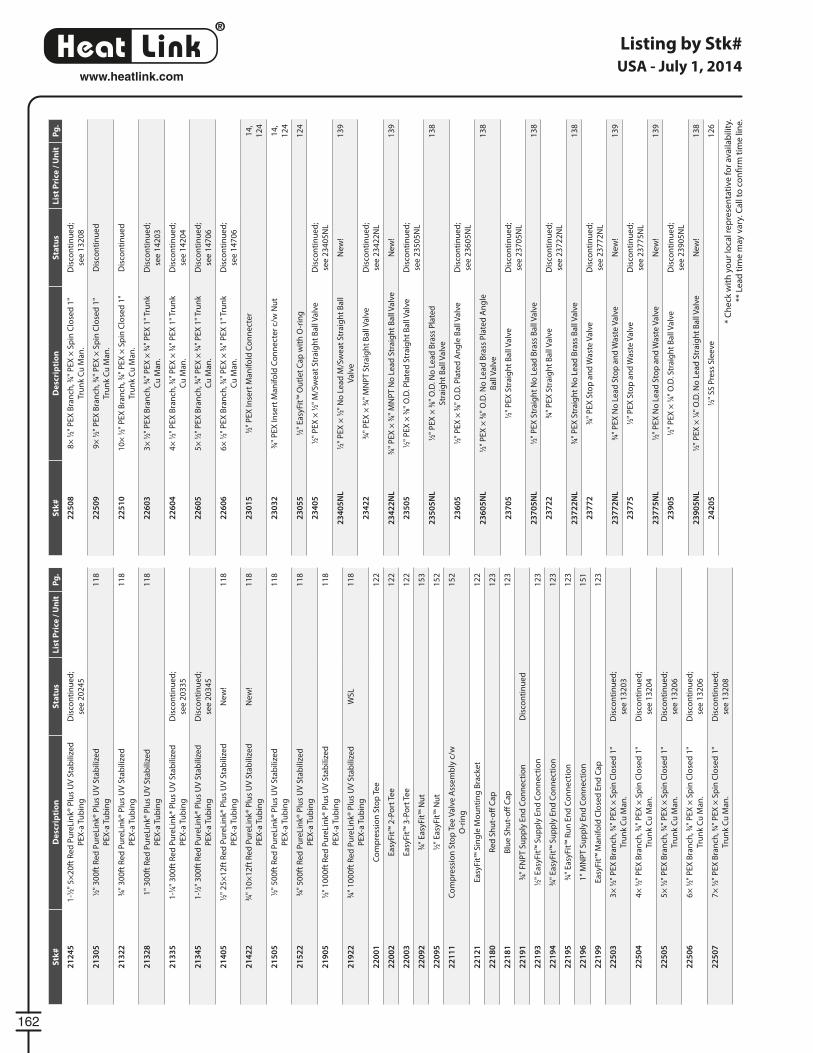
®
LinkHeat
162
www.heatlink.com
Listing by Stk#
* C
he
ck w
ith
yo
ur
loca
l re
pre
sen
tati
ve f
or
ava
ilab
ility
.
** L
ea
d t
ime
may
va
ry. C
all
to c
on
fi rm
tim
e li
ne
.
USA - July 1, 2014S
tk#
De
scri
pti
on
Sta
tus
Lis
t P
rice
/ U
nit
Pg
.
21
24
51
-1⁄2"
5×
20
ft R
ed
Pu
reLi
nk®
Plu
s U
V S
tab
ilize
d
PE
X-a
Tu
bin
g
Dis
con
tin
ue
d;
see
20
24
5
21
30
51⁄2"
30
0ft
Re
d P
ure
Lin
k® P
lus
UV
Sta
bili
zed
PE
X-a
Tu
bin
g
11
8
21
32
23⁄4"
30
0ft
Re
d P
ure
Lin
k® P
lus
UV
Sta
bili
zed
PE
X-a
Tu
bin
g
11
8
21
32
81
" 3
00
ft R
ed
Pu
reLi
nk®
Plu
s U
V S
tab
ilize
d
PE
X-a
Tu
bin
g
11
8
21
33
51
-1⁄4"
30
0ft
Re
d P
ure
Lin
k® P
lus
UV
Sta
bili
zed
PE
X-a
Tu
bin
g
Dis
con
tin
ue
d;
see
20
33
5
21
34
51
-1⁄2"
30
0ft
Re
d P
ure
Lin
k® P
lus
UV
Sta
bili
zed
PE
X-a
Tu
bin
g
Dis
con
tin
ue
d;
see
20
34
5
21
40
51⁄2"
25
×1
2ft
Re
d P
ure
Lin
k® P
lus
UV
Sta
bili
zed
PE
X-a
Tu
bin
g
Ne
w!
11
8
21
42
23⁄4"
10
×1
2ft
Re
d P
ure
Lin
k® P
lus
UV
Sta
bili
zed
PE
X-a
Tu
bin
g
Ne
w!
11
8
21
50
51⁄2"
50
0ft
Re
d P
ure
Lin
k® P
lus
UV
Sta
bili
zed
PE
X-a
Tu
bin
g
11
8
21
52
23⁄4"
50
0ft
Re
d P
ure
Lin
k® P
lus
UV
Sta
bili
zed
PE
X-a
Tu
bin
g
11
8
21
90
51⁄2"
10
00
ft R
ed
Pu
reLi
nk®
Plu
s U
V S
tab
ilize
d
PE
X-a
Tu
bin
g
11
8
21
92
23⁄4"
10
00
ft R
ed
Pu
reLi
nk®
Plu
s U
V S
tab
ilize
d
PE
X-a
Tu
bin
g
WS
L1
18
22
00
1C
om
pre
ssio
n S
top
Te
e1
22
22
00
2E
asy
Fit™
2-P
ort
Te
e1
22
22
00
3E
asy
Fit™
3-P
ort
Te
e1
22
22
09
23⁄4"
Ea
syFi
t™ N
ut
15
3
22
09
51⁄2"
Ea
syFi
t™ N
ut
15
2
22
11
1C
om
pre
ssio
n S
top
Te
e V
alv
e A
sse
mb
ly c
/w
O-r
ing
15
2
22
12
1E
asy
Fit™
Sin
gle
Mo
un
tin
g B
rack
et
12
2
22
18
0R
ed
Sh
ut-
off
Ca
p1
23
22
18
1B
lue
Sh
ut-
off
Ca
p1
23
22
19
13⁄4"
FN
PT
Su
pp
ly E
nd
Co
nn
ect
ion
Dis
con
tin
ue
d
22
19
31⁄2"
Ea
syFi
t™ S
up
ply
En
d C
on
ne
ctio
n1
23
22
19
43⁄4"
Ea
syFi
t™ S
up
ply
En
d C
on
ne
ctio
n1
23
22
19
53⁄4"
Ea
syFi
t™ R
un
En
d C
on
ne
ctio
n1
23
22
19
61
" M
NP
T S
up
ply
En
d C
on
ne
ctio
n1
51
22
19
9E
asy
Fit™
Ma
nif
old
Clo
sed
En
d C
ap
12
3
22
50
33
× 1
⁄2" P
EX
Bra
nch
, 3⁄4"
PE
X ×
Sp
in C
lose
d 1
"
Tru
nk
Cu
Ma
n.
Dis
con
tin
ue
d;
see
13
20
3
22
50
44
× 1
⁄2" P
EX
Bra
nch
, 3⁄4"
PE
X ×
Sp
in C
lose
d 1
"
Tru
nk
Cu
Ma
n.
Dis
con
tin
ue
d;
see
13
20
4
22
50
55
× 1
⁄2" P
EX
Bra
nch
, 3⁄4"
PE
X ×
Sp
in C
lose
d 1
"
Tru
nk
Cu
Ma
n.
Dis
con
tin
ue
d;
see
13
20
6
22
50
66
× 1
⁄2" P
EX
Bra
nch
, 3⁄4"
PE
X ×
Sp
in C
lose
d 1
"
Tru
nk
Cu
Ma
n.
Dis
con
tin
ue
d;
see
13
20
6
22
50
77
× 1
⁄2" P
EX
Bra
nch
, 3⁄4"
PE
X ×
Sp
in C
lose
d 1
"
Tru
nk
Cu
Ma
n.
Dis
con
tin
ue
d;
see
13
20
8
Stk
#D
esc
rip
tio
nS
tatu
sL
ist
Pri
ce /
Un
itP
g.
22
50
88
× 1
⁄2" P
EX
Bra
nch
, 3⁄4"
PE
X ×
Sp
in C
lose
d 1
"
Tru
nk
Cu
Ma
n.
Dis
con
tin
ue
d;
see
13
20
8
22
50
99
× 1
⁄2" P
EX
Bra
nch
, 3⁄4"
PE
X ×
Sp
in C
lose
d 1
"
Tru
nk
Cu
Ma
n.
Dis
con
tin
ue
d
22
51
01
0×
1⁄2"
PE
X B
ran
ch, 3
⁄4" P
EX
× S
pin
Clo
sed
1"
Tru
nk
Cu
Ma
n.
Dis
con
tin
ue
d
22
60
33
× 1
⁄2" P
EX
Bra
nch
, 3⁄4"
PE
X ×
3⁄4"
PE
X 1
" Tr
un
k
Cu
Ma
n.
Dis
con
tin
ue
d;
see
14
20
3
22
60
44
× 1
⁄2" P
EX
Bra
nch
, 3⁄4"
PE
X ×
3⁄4"
PE
X 1
" Tr
un
k
Cu
Ma
n.
Dis
con
tin
ue
d;
see
14
20
4
22
60
55
× 1
⁄2" P
EX
Bra
nch
, 3⁄4"
PE
X ×
3⁄4"
PE
X 1
" Tr
un
k
Cu
Ma
n.
Dis
con
tin
ue
d;
see
14
70
6
22
60
66
× 1
⁄2" P
EX
Bra
nch
, 3⁄4"
PE
X ×
3⁄4"
PE
X 1
" Tr
un
k
Cu
Ma
n.
Dis
con
tin
ue
d;
see
14
70
6
23
01
51⁄2"
PE
X In
sert
Ma
nif
old
Co
nn
ect
er
14
,
12
4
23
03
23⁄4"
PE
X In
sert
Ma
nif
old
Co
nn
ect
er
c/w
Nu
t1
4,
12
4
23
05
51⁄2"
Ea
syFi
t™ O
utl
et
Ca
p w
ith
O-r
ing
12
4
23
40
51⁄2"
PE
X ×
1⁄2"
M/S
we
at
Str
aig
ht
Ba
ll V
alv
eD
isco
nti
nu
ed
;
see
23
40
5N
L
23
40
5N
L1⁄2"
PE
X ×
1⁄2"
No
Le
ad
M/S
we
at
Str
aig
ht
Ba
ll
Va
lve
Ne
w!
13
9
23
42
23⁄4"
PE
X ×
3⁄4"
MN
PT
Str
aig
ht
Ba
ll V
alv
eD
isco
nti
nu
ed
;
see
23
42
2N
L
23
42
2N
L3⁄4"
PE
X ×
3⁄4"
MN
PT
No
Le
ad
Str
aig
ht
Ba
ll V
alv
eN
ew
!1
39
23
50
51⁄2"
PE
X ×
3⁄8"
O.D
. Pla
ted
Str
aig
ht
Ba
ll V
alv
eD
isco
nti
nu
ed
;
see
23
50
5N
L
23
50
5N
L1⁄2"
PE
X ×
3⁄8"
O.D
. No
Le
ad
Bra
ss P
late
d
Str
aig
ht
Ba
ll V
alv
e
13
8
23
60
51⁄2"
PE
X ×
3⁄8"
O.D
. Pla
ted
An
gle
Ba
ll V
alv
eD
isco
nti
nu
ed
;
see
23
60
5N
L
23
60
5N
L1⁄2"
PE
X ×
3⁄8"
O.D
. No
Le
ad
Bra
ss P
late
d A
ng
le
Ba
ll V
alv
e
13
8
23
70
51⁄2"
PE
X S
tra
igh
t B
all
Va
lve
Dis
con
tin
ue
d;
see
23
70
5N
L
23
70
5N
L1⁄2"
PE
X S
tra
igh
t N
o L
ea
d B
rass
Ba
ll V
alv
e1
38
23
72
23⁄4"
PE
X S
tra
igh
t B
all
Va
lve
Dis
con
tin
ue
d;
see
23
72
2N
L
23
72
2N
L3⁄4"
PE
X S
tra
igh
t N
o L
ea
d B
rass
Ba
ll V
alv
e1
38
23
77
23⁄4"
PE
X S
top
an
d W
ast
e V
alv
eD
isco
nti
nu
ed
;
see
23
77
2N
L
23
77
2N
L3⁄4"
PE
X N
o L
ea
d S
top
an
d W
ast
e V
alv
eN
ew
!1
39
23
77
51⁄2"
PE
X S
top
an
d W
ast
e V
alv
eD
isco
nti
nu
ed
;
see
23
77
5N
L
23
77
5N
L1⁄2"
PE
X N
o L
ea
d S
top
an
d W
ast
e V
alv
eN
ew
!1
39
23
90
51⁄2"
PE
X ×
1⁄4"
O.D
. Str
aig
ht
Ba
ll V
alv
eD
isco
nti
nu
ed
;
see
23
90
5N
L
23
90
5N
L1⁄2"
PE
X ×
1⁄4"
O.D
. No
Le
ad
Str
aig
ht
Ba
ll V
alv
eN
ew
!1
38
24
20
51⁄2"
SS
Pre
ss S
lee
ve1
26
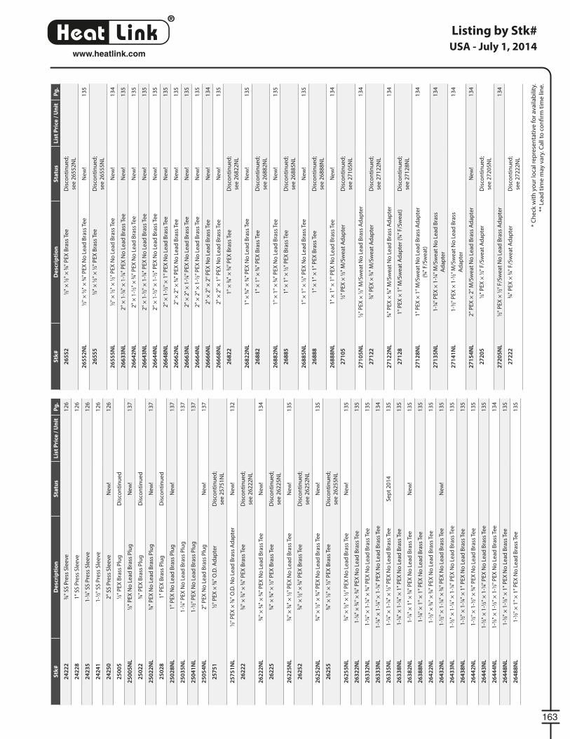
®
LinkHeat
163
www.heatlink.com
Listing by Stk#
* C
he
ck w
ith
yo
ur
loca
l re
pre
sen
tati
ve f
or
ava
ilab
ility
.
** L
ea
d t
ime
may
va
ry. C
all
to c
on
fi rm
tim
e li
ne
.
USA - July 1, 2014S
tk#
De
scri
pti
on
Sta
tus
Lis
t P
rice
/ U
nit
Pg
.
24
22
23⁄4"
SS
Pre
ss S
lee
ve1
26
24
22
81
" S
S P
ress
Sle
eve
12
6
24
23
51
-1⁄4"
SS
Pre
ss S
lee
ve1
26
24
24
11
-1⁄2"
SS
Pre
ss S
lee
ve1
26
24
25
02
" S
S P
ress
Sle
eve
Ne
w!
12
6
25
00
51⁄2"
PE
X B
rass
Plu
gD
isco
nti
nu
ed
25
00
5N
L1⁄2"
PE
X N
o L
ea
d B
rass
Plu
gN
ew
!1
37
25
02
23⁄4"
PE
X B
rass
Plu
gD
isco
nti
nu
ed
25
02
2N
L3⁄4"
PE
X N
o L
ea
d B
rass
Plu
gN
ew
!1
37
25
02
81
" P
EX
Bra
ss P
lug
Dis
con
tin
ue
d
25
02
8N
L1
" P
EX
No
Le
ad
Bra
ss P
lug
Ne
w!
13
7
25
03
5N
L1
-1⁄4"
PE
X N
o L
ea
d B
rass
Plu
g1
37
25
04
1N
L1
-1⁄2"
PE
X N
o L
ea
d B
rass
Plu
g1
37
25
05
4N
L2
" P
EX
No
Le
ad
Bra
ss P
lug
Ne
w!
13
7
25
75
11⁄2"
PE
X ×
3⁄8"
O.D
. Ad
ap
ter
Dis
con
tin
ue
d;
see
25
75
1N
L
25
75
1N
L1⁄2"
PE
X ×
3⁄8"
O.D
. No
Le
ad
Bra
ss A
da
pte
rN
ew
!1
32
26
22
23⁄4"
× 3
⁄4" ×
3⁄4"
PE
X B
rass
Te
eD
isco
nti
nu
ed
;
see
26
22
2N
L
26
22
2N
L3⁄4"
× 3
⁄4" ×
3⁄4"
PE
X N
o L
ea
d B
rass
Te
eN
ew
!1
34
26
22
53⁄4"
× 3
⁄4" ×
1⁄2"
PE
X B
rass
Te
eD
isco
nti
nu
ed
;
see
26
22
5N
L
26
22
5N
L3⁄4"
× 3
⁄4" ×
1⁄2"
PE
X N
o L
ea
d B
rass
Te
eN
ew
!1
35
26
25
23⁄4"
× 1
⁄2" ×
3⁄4"
PE
X B
rass
Te
eD
isco
nti
nu
ed
;
see
26
25
2N
L
26
25
2N
L3⁄4"
× 1
⁄2" ×
3⁄4"
PE
X N
o L
ea
d B
rass
Te
eN
ew
!1
35
26
25
53⁄4"
× 1
⁄2" ×
1⁄2"
PE
X B
rass
Te
eD
isco
nti
nu
ed
;
see
26
25
5N
L
26
25
5N
L3⁄4"
× 1
⁄2" ×
1⁄2"
PE
X N
o L
ea
d B
rass
Te
eN
ew
!1
35
26
32
2N
L1
-1⁄4"
× 3
⁄4" ×
3⁄4"
PE
X N
o L
ea
d B
rass
Te
e1
35
26
33
2N
L1
-1⁄4"
× 1
-1⁄4"
× 3
⁄4" P
EX
No
Le
ad
Bra
ss T
ee
13
5
26
33
3N
L1
-1⁄4"
× 1
-1⁄4"
× 1
-1⁄4"
PE
X N
o L
ea
d B
rass
Te
e1
34
26
33
5N
L1
-1⁄4"
× 1
-1⁄4"
× 1
⁄2" P
EX
No
Le
ad
Bra
ss T
ee
Se
pt
20
14
13
5
26
33
8N
L1
-1⁄4"
× 1
-1⁄4"
× 1
" P
EX
No
Le
ad
Bra
ss T
ee
13
5
26
38
2N
L1
-1⁄4"
× 1
" ×
3⁄4"
PE
X N
o L
ea
d B
rass
Te
eN
ew
!1
35
26
38
8N
L1
-1⁄4"
× 1
" ×
1"
PE
X N
o L
ea
d B
rass
Te
e1
35
26
42
2N
L1
-1⁄2"
× 3
⁄4" ×
3⁄4"
PE
X N
o L
ea
d B
rass
Te
e1
35
26
43
2N
L1
-1⁄2"
× 1
-1⁄4"
× 3
⁄4" P
EX
No
Le
ad
Bra
ss T
ee
Ne
w!
13
5
26
43
3N
L1
-1⁄2"
× 1
-1⁄4"
× 1
-1⁄4"
PE
X N
o L
ea
d B
rass
Te
e1
35
26
43
8N
L1
-1⁄2"
× 1
-1⁄4"
× 1
" P
EX
No
Le
ad
Bra
ss T
ee
13
5
26
44
2N
L1
-1⁄2"
× 1
-1⁄2"
× 3
⁄4" P
EX
No
Le
ad
Bra
ss T
ee
13
5
26
44
3N
L1
-1⁄2"
× 1
-1⁄2"
× 1
-1⁄4"
PE
X N
o L
ea
d B
rass
Te
e1
35
26
44
4N
L1
-1⁄2"
× 1
-1⁄2"
× 1
-1⁄2"
PE
X N
o L
ea
d B
rass
Te
e1
34
26
44
8N
L1
-1⁄2"
× 1
-1⁄2"
× 1
" P
EX
No
Le
ad
Bra
ss T
ee
13
5
26
48
8N
L1
-1⁄2"
× 1
" ×
1"
PE
X N
o L
ea
d B
rass
Te
e1
35
Stk
#D
esc
rip
tio
nS
tatu
sL
ist
Pri
ce /
Un
itP
g.
26
55
21⁄2"
× 1
⁄2" ×
3⁄4"
PE
X B
rass
Te
eD
isco
nti
nu
ed
;
see
26
55
2N
L
26
55
2N
L1⁄2"
× 1
⁄2" ×
3⁄4"
PE
X N
o L
ea
d B
rass
Te
eN
ew
!1
35
26
55
51⁄2"
× 1
⁄2" ×
1⁄2"
PE
X B
rass
Te
eD
isco
nti
nu
ed
;
see
26
55
5N
L
26
55
5N
L1⁄2"
× 1
⁄2" ×
1⁄2"
PE
X N
o L
ea
d B
rass
Te
eN
ew
!1
34
26
63
3N
L2
" ×
1-1
⁄4" ×
1-1
⁄4" P
EX
No
Le
ad
Bra
ss T
ee
Ne
w!
13
5
26
64
2N
L2
" ×
1-1
⁄2" ×
3⁄4"
PE
X N
o L
ea
d B
rass
Te
eN
ew
!1
35
26
64
3N
L2
" ×
1-1
⁄2" ×
1-1
⁄4" P
EX
No
Le
ad
Bra
ss T
ee
Ne
w!
13
5
26
64
4N
L2
" ×
1-1
⁄2" ×
1-1
⁄2" P
EX
No
Le
ad
Bra
ss T
ee
Ne
w!
13
5
26
64
8N
L2
" ×
1-1
⁄2" ×
1"
PE
X N
o L
ea
d B
rass
Te
eN
ew
!1
35
26
66
2N
L2
" ×
2"
× 3
⁄4" P
EX
No
Le
ad
Bra
ss T
ee
Ne
w!
13
5
26
66
3N
L2
" ×
2"
× 1
-1⁄4"
PE
X N
o L
ea
d B
rass
Te
eN
ew
!1
35
26
66
4N
L2
" ×
2"
× 1
-1⁄2"
PE
X N
o L
ea
d B
rass
Te
eN
ew
!1
35
26
66
6N
L2
" ×
2"
× 2
" P
EX
No
Le
ad
Bra
ss T
ee
Ne
w!
13
4
26
66
8N
L2
" ×
2"
× 1
" P
EX
No
Le
ad
Bra
ss T
ee
Ne
w!
13
5
26
82
21
" ×
3⁄4"
× 3
⁄4" P
EX
Bra
ss T
ee
Dis
con
tin
ue
d;
see
26
82
2N
L
26
82
2N
L1
" ×
3⁄4"
× 3
⁄4" P
EX
No
Le
ad
Bra
ss T
ee
Ne
w!
13
5
26
88
21
" ×
1"
× 3
⁄4" P
EX
Bra
ss T
ee
Dis
con
tin
ue
d;
see
26
88
2N
L
26
88
2N
L1
" ×
1"
× 3
⁄4" P
EX
No
Le
ad
Bra
ss T
ee
Ne
w!
13
5
26
88
51
" ×
1"
× 1
⁄2" P
EX
Bra
ss T
ee
Dis
con
tin
ue
d;
see
26
88
5N
L
26
88
5N
L1
" ×
1"
× 1
⁄2" P
EX
No
Le
ad
Bra
ss T
ee
Ne
w!
13
5
26
88
81
" ×
1"
× 1
" P
EX
Bra
ss T
ee
Dis
con
tin
ue
d;
see
26
88
8N
L
26
88
8N
L1
" ×
1"
× 1
" P
EX
No
Le
ad
Bra
ss T
ee
Ne
w!
13
4
27
10
51⁄2"
PE
X ×
1⁄2"
M/S
we
at
Ad
ap
ter
Dis
con
tin
ue
d;
see
27
10
5N
L
27
10
5N
L1⁄2"
PE
X ×
1⁄2"
M/S
we
at
No
Le
ad
Bra
ss A
da
pte
r1
34
27
12
23⁄4"
PE
X ×
3⁄4"
M/S
we
at
Ad
ap
ter
Dis
con
tin
ue
d;
see
27
12
2N
L
27
12
2N
L3⁄4"
PE
X ×
3⁄4"
M/S
we
at
No
Le
ad
Bra
ss A
da
pte
r1
34
27
12
81
" P
EX
× 1
" M
/Sw
ea
t A
da
pte
r (3
⁄4" F
/Sw
ea
t)D
isco
nti
nu
ed
;
see
27
12
8N
L
27
12
8N
L1
" P
EX
× 1
" M
/Sw
ea
t N
o L
ea
d B
rass
Ad
ap
ter
(3⁄4"
F/S
we
at)
13
4
27
13
5N
L1
-1⁄4"
PE
X ×
1-1
⁄4" M
/Sw
ea
t N
o L
ea
d B
rass
Ad
ap
ter
13
4
27
14
1N
L1
-1⁄2"
PE
X ×
1-1
⁄2" M
/Sw
ea
t N
o L
ea
d B
rass
Ad
ap
ter
13
4
27
15
4N
L2
" P
EX
× 2
" M
/Sw
ea
t N
o L
ea
d B
rass
Ad
ap
ter
Ne
w!
13
4
27
20
51⁄2"
PE
X ×
1⁄2"
F/S
we
at
Ad
ap
ter
Dis
con
tin
ue
d;
see
27
20
5N
L
27
20
5N
L1⁄2"
PE
X ×
1⁄2"
F/S
we
at
No
Le
ad
Bra
ss A
da
pte
r1
34
27
22
23⁄4"
PE
X ×
3⁄4"
F/S
we
at
Ad
ap
ter
Dis
con
tin
ue
d;
see
27
22
2N
L
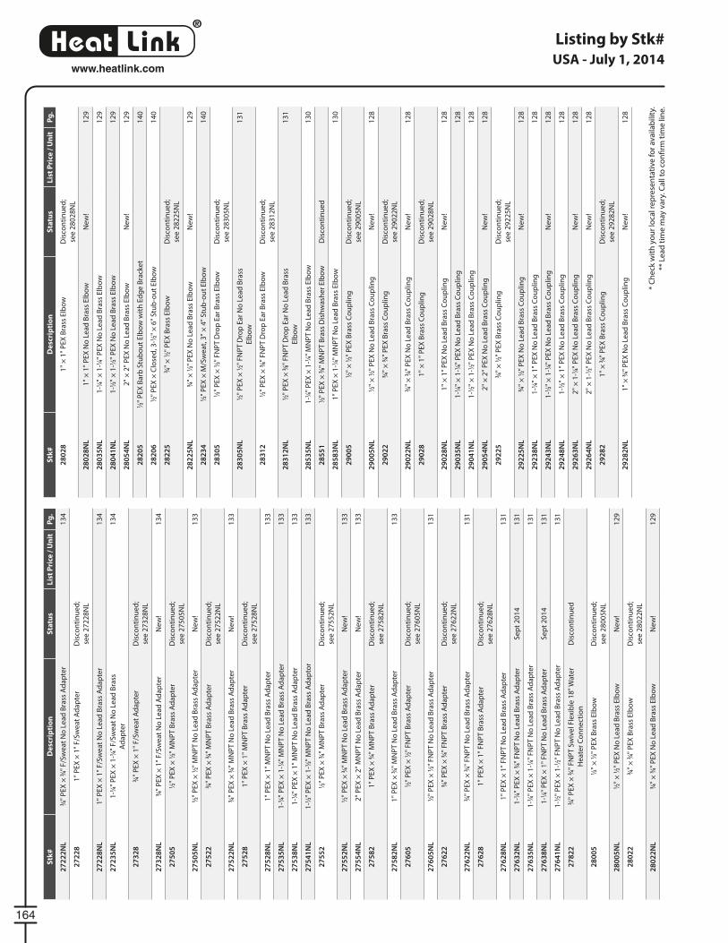
®
LinkHeat
164
www.heatlink.com
Listing by Stk#
* C
he
ck w
ith
yo
ur
loca
l re
pre
sen
tati
ve f
or
ava
ilab
ility
.
** L
ea
d t
ime
may
va
ry. C
all
to c
on
fi rm
tim
e li
ne
.
USA - July 1, 2014S
tk#
De
scri
pti
on
Sta
tus
Lis
t P
rice
/ U
nit
Pg
.
27
22
2N
L3⁄4"
PE
X ×
3⁄4"
F/S
we
at
No
Le
ad
Bra
ss A
da
pte
r1
34
27
22
81
" P
EX
× 1
" F
/Sw
ea
t A
da
pte
rD
isco
nti
nu
ed
;
see
27
22
8N
L
27
22
8N
L1
" P
EX
× 1
" F
/Sw
ea
t N
o L
ea
d B
rass
Ad
ap
ter
13
4
27
23
5N
L1
-1⁄4"
PE
X ×
1-1
⁄4" F
/Sw
ea
t N
o L
ea
d B
rass
Ad
ap
ter
13
4
27
32
83⁄4"
PE
X ×
1"
F/S
we
at
Ad
ap
ter
Dis
con
tin
ue
d;
see
27
32
8N
L
27
32
8N
L3⁄4"
PE
X ×
1"
F/S
we
at
No
Le
ad
Ad
ap
ter
Ne
w!
13
4
27
50
51⁄2"
PE
X ×
1⁄2"
MN
PT
Bra
ss A
da
pte
rD
isco
nti
nu
ed
;
see
27
50
5N
L
27
50
5N
L1⁄2"
PE
X ×
1⁄2"
MN
PT
No
Le
ad
Bra
ss A
da
pte
rN
ew
!1
33
27
52
23⁄4"
PE
X ×
3⁄4"
MN
PT
Bra
ss A
da
pte
rD
isco
nti
nu
ed
;
see
27
52
2N
L
27
52
2N
L3⁄4"
PE
X ×
3⁄4"
MN
PT
No
Le
ad
Bra
ss A
da
pte
rN
ew
!1
33
27
52
81
" P
EX
× 1
" M
NP
T B
rass
Ad
ap
ter
Dis
con
tin
ue
d;
see
27
52
8N
L
27
52
8N
L1
" P
EX
× 1
" M
NP
T N
o L
ea
d B
rass
Ad
ap
ter
13
3
27
53
5N
L1
-1⁄4"
PE
X ×
1-1
⁄4" M
NP
T N
o L
ea
d B
rass
Ad
ap
ter
13
3
27
53
8N
L1
-1⁄4"
PE
X ×
1"
MN
PT
No
Le
ad
Bra
ss A
da
pte
r1
33
27
54
1N
L1
-1⁄2"
PE
X ×
1-1
⁄2" M
NP
T N
o L
ea
d B
rass
Ad
ap
tor
13
3
27
55
21⁄2"
PE
X ×
3⁄4"
MN
PT
Bra
ss A
da
pte
rD
isco
nti
nu
ed
;
see
27
55
2N
L
27
55
2N
L1⁄2"
PE
X ×
3⁄4"
MN
PT
No
Le
ad
Bra
ss A
da
pte
rN
ew
!1
33
27
55
4N
L2
" P
EX
× 2
" M
NP
T N
o L
ea
d B
rass
Ad
ap
ter
Ne
w!
13
3
27
58
21
" P
EX
× 3
⁄4" M
NP
T B
rass
Ad
ap
ter
Dis
con
tin
ue
d;
see
27
58
2N
L
27
58
2N
L1
" P
EX
× 3
⁄4" M
NP
T N
o L
ea
d B
rass
Ad
ap
ter
13
3
27
60
51⁄2"
PE
X ×
1⁄2"
FN
PT
Bra
ss A
da
pte
rD
isco
nti
nu
ed
;
see
27
60
5N
L
27
60
5N
L1⁄2"
PE
X ×
1⁄2"
FN
PT
No
Le
ad
Bra
ss A
da
pte
r1
31
27
62
23⁄4"
PE
X ×
3⁄4"
FN
PT
Bra
ss A
da
pte
rD
isco
nti
nu
ed
;
see
27
62
2N
L
27
62
2N
L3⁄4"
PE
X ×
3⁄4"
FN
PT
No
Le
ad
Bra
ss A
da
pte
r1
31
27
62
81
" P
EX
× 1
" F
NP
T B
rass
Ad
ap
ter
Dis
con
tin
ue
d;
see
27
62
8N
L
27
62
8N
L1
" P
EX
× 1
" F
NP
T N
o L
ea
d B
rass
Ad
ap
ter
13
1
27
63
2N
L1
-1⁄4"
PE
X ×
3⁄4"
FN
PT
No
Le
ad
Bra
ss A
da
pte
rS
ep
t 2
01
41
31
27
63
5N
L1
-1⁄4"
PE
X ×
1-1
⁄4" F
NP
T N
o L
ea
d B
rass
Ad
ap
ter
13
1
27
63
8N
L1
-1⁄4"
PE
X ×
1"
FN
PT
No
Le
ad
Bra
ss A
da
pte
rS
ep
t 2
01
41
31
27
64
1N
L1
-1⁄2"
PE
X ×
1-1
⁄2" F
NP
T N
o L
ea
d B
rass
Ad
ap
ter
13
1
27
82
23⁄4"
PE
X ×
3⁄4"
FN
PT
Sw
ive
l Fle
xib
le 1
8"
Wat
er
He
ate
r C
on
ne
ctio
n
Dis
con
tin
ue
d
28
00
51⁄2"
× 1
⁄2" P
EX
Bra
ss E
lbo
wD
isco
nti
nu
ed
;
see
28
00
5N
L
28
00
5N
L1⁄2"
× 1
⁄2" P
EX
No
Le
ad
Bra
ss E
lbo
wN
ew
!1
29
28
02
23⁄4"
× 3
⁄4" P
EX
Bra
ss E
lbo
wD
isco
nti
nu
ed
;
see
28
02
2N
L
28
02
2N
L3⁄4"
× 3
⁄4" P
EX
No
Le
ad
Bra
ss E
lbo
wN
ew
!1
29
Stk
#D
esc
rip
tio
nS
tatu
sL
ist
Pri
ce /
Un
itP
g.
28
02
81
" ×
1"
PE
X B
rass
Elb
ow
Dis
con
tin
ue
d;
see
28
02
8N
L
28
02
8N
L1
" ×
1"
PE
X N
o L
ea
d B
rass
Elb
ow
Ne
w!
12
9
28
03
5N
L1
-1⁄4"
× 1
-1⁄4"
PE
X N
o L
ea
d B
rass
Elb
ow
12
9
28
04
1N
L1
-1⁄2"
× 1
-1⁄2"
PE
X N
o L
ea
d B
rass
Elb
ow
12
9
28
05
4N
L2
" ×
2"
PE
X N
o L
ea
d B
rass
Elb
ow
Ne
w!
12
9
28
20
51⁄2"
PE
X B
arb
Stu
bo
ut
Elb
ow
wit
h E
dg
e B
rack
et
14
0
28
20
61⁄2"
PE
X ×
Clo
sed
, 3-1
⁄2" ×
6"
Stu
b-o
ut
Elb
ow
14
0
28
22
53⁄4"
× 1
⁄2" P
EX
Bra
ss E
lbo
wD
isco
nti
nu
ed
;
see
28
22
5N
L
28
22
5N
L3⁄4"
× 1
⁄2" P
EX
No
Le
ad
Bra
ss E
lbo
wN
ew
!1
29
28
23
41⁄2"
PE
X ×
M/S
we
at,
3"
× 4
" S
tub
-ou
t E
lbo
w1
40
28
30
51⁄2"
PE
X ×
1⁄2"
FN
PT
Dro
p E
ar
Bra
ss E
lbo
wD
isco
nti
nu
ed
;
see
28
30
5N
L
28
30
5N
L1⁄2"
PE
X ×
1⁄2"
FN
PT
Dro
p E
ar
No
Le
ad
Bra
ss
Elb
ow
13
1
28
31
21⁄2"
PE
X ×
3⁄8"
FN
PT
Dro
p E
ar
Bra
ss E
lbo
wD
isco
nti
nu
ed
;
see
28
31
2N
L
28
31
2N
L1⁄2"
PE
X ×
3⁄8"
FN
PT
Dro
p E
ar
No
Le
ad
Bra
ss
Elb
ow
13
1
28
53
5N
L1
-1⁄4"
PE
X ×
1-1
⁄4" M
NP
T N
o L
ea
d B
rass
Elb
ow
13
0
28
55
11⁄2"
PE
X ×
3⁄8"
MN
PT
Bra
ss D
ish
wa
she
r E
lbo
wD
isco
nti
nu
ed
28
58
3N
L1
" P
EX
× 1
-1⁄4"
MN
PT
No
Le
ad
Bra
ss E
lbo
w1
30
29
00
51⁄2"
× 1
⁄2" P
EX
Bra
ss C
ou
plin
gD
isco
nti
nu
ed
;
see
29
00
5N
L
29
00
5N
L1⁄2"
× 1
⁄2" P
EX
No
Le
ad
Bra
ss C
ou
plin
gN
ew
!1
28
29
02
23⁄4"
× 3
⁄4" P
EX
Bra
ss C
ou
plin
gD
isco
nti
nu
ed
;
see
29
02
2N
L
29
02
2N
L3⁄4"
× 3
⁄4" P
EX
No
Le
ad
Bra
ss C
ou
plin
gN
ew
!1
28
29
02
81
" ×
1"
PE
X B
rass
Co
up
ling
Dis
con
tin
ue
d;
see
29
02
8N
L
29
02
8N
L1
" ×
1"
PE
X N
o L
ea
d B
rass
Co
up
ling
Ne
w!
12
8
29
03
5N
L1
-1⁄4"
× 1
-1⁄4"
PE
X N
o L
ea
d B
rass
Co
up
ling
12
8
29
04
1N
L1
-1⁄2"
× 1
-1⁄2"
PE
X N
o L
ea
d B
rass
Co
up
ling
12
8
29
05
4N
L2
" ×
2"
PE
X N
o L
ea
d B
rass
Co
up
ling
Ne
w!
12
8
29
22
53⁄4"
× 1
⁄2" P
EX
Bra
ss C
ou
plin
gD
isco
nti
nu
ed
;
see
29
22
5N
L
29
22
5N
L3⁄4"
× 1
⁄2" P
EX
No
Le
ad
Bra
ss C
ou
plin
gN
ew
!1
28
29
23
8N
L1
-1⁄4"
× 1
" P
EX
No
Le
ad
Bra
ss C
ou
plin
g1
28
29
24
3N
L1
-1⁄2"
× 1
-1⁄4"
PE
X N
o L
ea
d B
rass
Co
up
ling
Ne
w!
12
8
29
24
8N
L1
-1⁄2"
× 1
" P
EX
No
Le
ad
Bra
ss C
ou
plin
g1
28
29
26
3N
L2
" ×
1-1
⁄4" P
EX
No
Le
ad
Bra
ss C
ou
plin
gN
ew
!1
28
29
26
4N
L2
" ×
1-1
⁄2" P
EX
No
Le
ad
Bra
ss C
ou
plin
gN
ew
!1
28
29
28
21
" ×
3⁄4"
PE
X B
rass
Co
up
ling
Dis
con
tin
ue
d;
see
29
28
2N
L
29
28
2N
L1
" ×
3⁄4"
PE
X N
o L
ea
d B
rass
Co
up
ling
Ne
w!
12
8
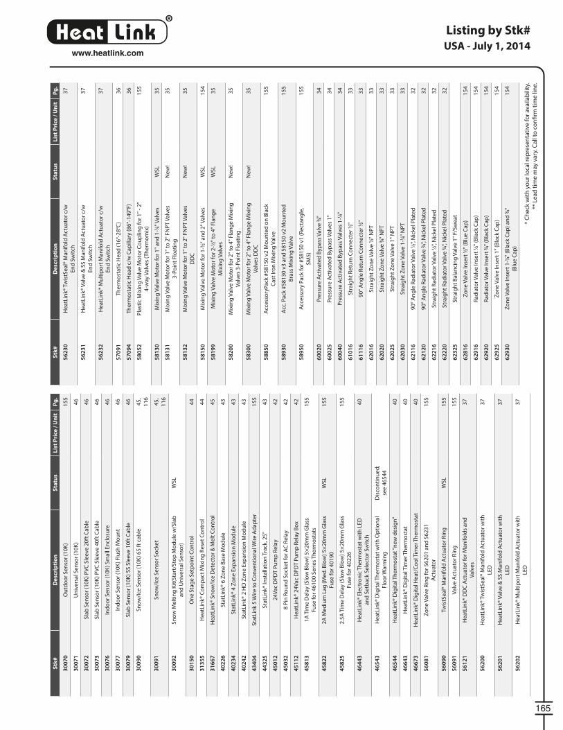
®
LinkHeat
165
www.heatlink.com
Listing by Stk#
* C
he
ck w
ith
yo
ur
loca
l re
pre
sen
tati
ve f
or
ava
ilab
ility
.
** L
ea
d t
ime
may
va
ry. C
all
to c
on
fi rm
tim
e li
ne
.
USA - July 1, 2014S
tk#
De
scri
pti
on
Sta
tus
Lis
t P
rice
/ U
nit
Pg
.
30
07
0O
utd
oo
r S
en
sor
(10
K)
15
5
30
07
1U
niv
ers
al S
en
sor
(10
K)
46
30
07
2S
lab
Se
nso
r (1
0K
) P
VC
Sle
eve
20
ft C
ab
le4
6
30
07
3S
lab
Se
nso
r (1
0K
) P
VC
Sle
eve
40
ft C
ab
le4
6
30
07
6In
do
or
Se
nso
r (1
0K
) S
ma
ll E
ncl
osu
re4
6
30
07
7In
do
or
Se
nso
r (1
0K
) Fl
ush
Mo
un
t4
6
30
07
9S
lab
Se
nso
r (1
0K
) S
S S
lee
ve 1
0ft
Ca
ble
46
30
09
0S
no
w/I
ce S
en
sor
(10
K)
65
ft
cab
le4
5,
11
6
30
09
1S
no
w/I
ce S
en
sor
So
cke
t4
5,
11
6
30
09
2S
no
w M
elt
ing
Kit
(Sta
rt/S
top
Mo
du
le w
/Sla
b
an
d U
niv
ers
al S
en
sor)
WS
L
30
15
0O
ne
Sta
ge
Se
tpo
int
Co
ntr
ol
44
31
35
5H
ea
tLin
k® C
om
pa
ct M
ixin
g R
ese
t C
on
tro
l4
4
31
66
7H
ea
tLin
k® S
no
w/I
ce D
ete
cto
r &
Me
lt C
on
tro
l4
5
40
22
6S
tatL
ink®
6 Z
on
e B
ase
Mo
du
le4
3
40
23
4S
tatL
ink®
4 Z
on
e E
xpa
nsi
on
Mo
du
le4
3
40
24
2S
tatL
ink®
2 H
D Z
on
e E
xpa
nsi
on
Mo
du
le4
3
43
40
4S
tatL
ink
5 W
ire
to
Co
nve
nti
on
al W
ire
Ad
ap
ter
15
5
44
32
5S
tatL
ink®
Inst
alla
tio
n T
rack
, 25
"4
3
45
01
22
4V
ac
DP
DT
Pu
mp
Re
lay
42
45
03
28
Pin
Ro
un
d S
ock
et
for
AC
Re
lay
42
45
11
2H
ea
tLin
k® 2
4V
ac
DP
DT
Pu
mp
Re
lay
Bo
x4
2
45
81
31
A T
ime
De
lay
(Slo
w B
low
) 5
×2
0m
m G
lass
Fuse
fo
r 4
61
00
Se
rie
s T
he
rmo
sta
ts
15
5
45
82
22
A M
ed
ium
La
g (
Me
d. B
low
) 5
×2
0m
m G
lass
Fuse
fo
r 4
01
90
WS
L1
55
45
82
52
.5A
Tim
e D
ela
y (S
low
Blo
w)
5×
20
mm
Gla
ss
Fuse
fo
r 4
02
26
15
5
46
44
3H
ea
tLin
k® E
lect
ron
ic T
he
rmo
sta
t w
ith
LE
D
an
d S
etb
ack
Se
lect
or
Sw
itch
40
46
54
3H
ea
tLin
k® D
igit
al T
he
rmo
sta
t w
ith
Op
tio
na
l
Flo
or
Wa
rmin
g
Dis
con
tin
ue
d;
see
46
54
4
46
54
4H
ea
tLin
k® D
igit
al T
he
rmo
sta
t "n
ew
de
sig
n"
40
46
64
3H
ea
tLin
k® D
igit
al T
ime
r T
he
rmo
sta
t4
0
46
67
3H
ea
tLin
k® D
igit
al H
ea
t/C
oo
l Tim
er
Th
erm
ost
at
40
56
08
1Z
on
e V
alv
e R
ing
fo
r 5
62
01
an
d 5
62
31
Act
ua
tor
15
5
56
09
0Tw
istS
ea
l® M
an
ifo
ld A
ctu
ato
r R
ing
WS
L1
55
56
09
1V
alv
e A
ctu
ato
r R
ing
15
5
56
12
1H
ea
tLin
k® D
DC
Act
ua
tor
for
Ma
nif
old
s a
nd
Va
lve
s
37
56
20
0H
ea
tLin
k® T
wis
tSe
al®
Ma
nif
old
Act
ua
tor
wit
h
LED
37
56
20
1H
ea
tLin
k® V
alv
e &
SS
Ma
nif
old
Act
ua
tor
wit
h
LED
37
56
20
2H
ea
tLin
k® M
ult
ipo
rt M
an
ifo
ld A
ctu
ato
r w
ith
LED
37
Stk
#D
esc
rip
tio
nS
tatu
sL
ist
Pri
ce /
Un
itP
g.
56
23
0H
ea
tLin
k® T
wis
tSe
al®
Ma
nif
old
Act
ua
tor
c/w
En
d S
wit
ch
37
56
23
1H
ea
tLin
k® V
alv
e &
SS
Ma
nif
old
Act
ua
tor
c/w
En
d S
wit
ch
37
56
23
2H
ea
tLin
k® M
ult
ipo
rt M
an
ifo
ld A
ctu
ato
r c/
w
En
d S
wit
ch
37
57
09
1T
he
rmo
sta
tic
He
ad
(1
6°-
28
°C)
36
57
09
4T
he
rmo
sta
tic
He
ad
c/w
Ca
pill
ary
(8
6°-
14
9°F
)3
6
58
05
2P
last
ic M
ixin
g V
alv
e M
oto
r C
ou
plin
g f
or
1"
- 2
"
4-w
ay V
alv
es
(Th
erm
om
ix)
15
5
58
13
0M
ixin
g V
alv
e M
oto
r fo
r 1
" a
nd
1-1
⁄4" V
alv
es
WS
L3
5
58
13
1M
ixin
g V
alv
e M
oto
r fo
r 1
" to
2"
FN
PT
Va
lve
s
3-P
oin
t Fl
oa
tin
g
Ne
w!
35
58
13
2M
ixin
g V
alv
e M
oto
r fo
r 1
" to
2"
FN
PT
Va
lve
s
DD
C
Ne
w!
35
58
15
0M
ixin
g V
alv
e M
oto
r fo
r 1
-1⁄2"
an
d 2
" V
alv
es
WS
L1
54
58
19
9M
ixin
g V
alv
e M
oto
r fo
r 2
-1⁄2"
to
4"
Fla
ng
e
Mix
ing
Va
lve
s
WS
L3
5
58
20
0M
ixin
g V
alv
e M
oto
r fo
r 2
" to
4"
Fla
ng
e M
ixin
g
Va
lve
s 3
-Po
int
Flo
ati
ng
Ne
w!
35
58
30
0M
ixin
g V
alv
e M
oto
r fo
r 2
" to
4"
Fla
ng
e M
ixin
g
Va
lve
s D
DC
Ne
w!
35
58
85
0A
cce
sso
ryP
ack
#5
81
50
v2
Mo
un
ted
on
Bla
ck
Ca
st Ir
on
Mix
ing
Va
lve
15
5
58
93
0A
cc. P
ack
#5
81
30
v3
an
d 5
81
50
v2
Mo
un
ted
Bra
ss M
ixin
g V
alv
e
15
5
58
95
0A
cce
sso
ry P
ack
fo
r #
58
15
0 v
1 (
Re
cta
ng
le,
SM
5)
15
5
60
02
0P
ress
ure
Act
iva
ted
Byp
ass
Va
lve
3⁄4"
34
60
02
5P
ress
ure
Act
iva
ted
Byp
ass
Va
lve
s 1
"3
4
60
04
0P
ress
ure
Act
iva
ted
Byp
ass
Va
lve
s 1
-1⁄4"
34
61
01
6S
tra
igh
t R
etu
rn C
on
ne
cte
r 1⁄2"
33
61
11
69
0°
An
gle
Re
turn
Co
nn
ect
er
1⁄2"
33
62
01
6S
tra
igh
t Z
on
e V
alv
e 1
⁄2" N
PT
33
62
02
0S
tra
igh
t Z
on
e V
alv
e 3
⁄4" N
PT
33
62
02
5S
tra
igh
t Z
on
e V
alv
e 1
" N
PT
33
62
03
0S
tra
igh
t Z
on
e V
alv
e 1
-1⁄4"
NP
T3
3
62
11
69
0°
An
gle
Ra
dia
tor
Va
lve
1⁄2"
, Nic
kel P
late
d3
2
62
12
09
0°
An
gle
Ra
dia
tor
Va
lve
3⁄4"
, Nic
kel P
late
d3
2
62
21
6S
tra
igh
t R
ad
iato
r V
alv
e 1
⁄2", N
icke
l Pla
ted
32
62
22
0S
tra
igh
t R
ad
iato
r V
alv
e 3
⁄4", N
icke
l Pla
ted
32
62
32
5S
tra
igh
t B
ala
nci
ng
Va
lve
1"
F/S
we
at
62
81
6Z
on
e V
alv
e In
sert
1⁄2"
(B
lue
Ca
p)
15
4
62
91
6R
ad
iato
r V
alv
e In
sert
1⁄2"
(B
lack
Ca
p)
15
4
62
92
0R
ad
iato
r V
alv
e In
sert
3⁄4"
(B
lack
Ca
p)
15
4
62
92
5Z
on
e V
alv
e In
sert
1"
(Bla
ck C
ap
)1
54
62
93
0Z
on
e V
alv
e In
sert
1-1
⁄4" (
Bla
ck C
ap
) a
nd
3⁄4"
(Blu
e C
ap
)
15
4
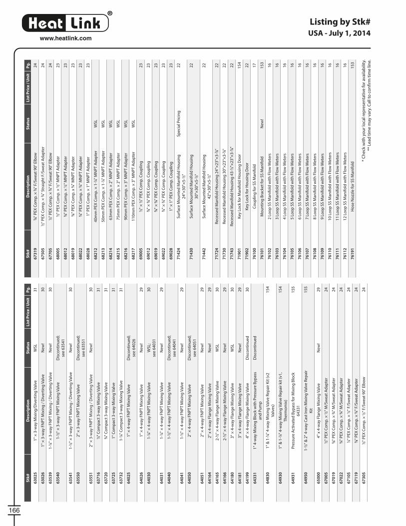
®
LinkHeat
166
www.heatlink.com
Listing by Stk#
* C
he
ck w
ith
yo
ur
loca
l re
pre
sen
tati
ve f
or
ava
ilab
ility
.
** L
ea
d t
ime
may
va
ry. C
all
to c
on
fi rm
tim
e li
ne
.
USA - July 1, 2014S
tk#
De
scri
pti
on
Sta
tus
Lis
t P
rice
/ U
nit
Pg
.
63
02
51
" ×
3-w
ay M
ixin
g/D
ive
rtin
g V
alv
eW
SL
31
63
02
61
" ×
3-w
ay F
NP
T M
ixin
g /
Div
ert
ing
Va
lve
Ne
w!
30
63
53
91
-1⁄4"
× 3
-way
FN
PT
Mix
ing
/ D
ive
rtin
g V
alv
eN
ew
!3
0
63
54
01
-1⁄2"
× 3
-way
FN
PT
Mix
ing
Va
lve
Dis
con
tin
ue
d;
see
63
54
1
63
54
11
-1⁄2"
× 3
-way
FN
PT
Mix
ing
/ D
ive
rtin
g V
alv
eN
ew
!3
0
63
55
02
" ×
3-w
ay F
NP
T M
ixin
g V
alv
eD
isco
nti
nu
ed
;
see
63
55
1
63
55
12
" ×
3-w
ay F
NP
T M
ixin
g /
Div
ert
ing
Va
lve
Ne
w!
30
63
71
61⁄2"
Co
mp
act
3-w
ay M
ixin
g V
alv
e3
1
63
72
03⁄4"
Co
mp
act
3-w
ay M
ixin
g V
alv
e3
1
63
72
51
" C
om
pa
ct 3
-way
Mix
ing
Va
lve
31
63
73
21
-1⁄4"
Co
mp
act
3-w
ay M
ixin
g V
alv
e3
1
64
02
51
" ×
4-w
ay F
NP
T M
ixin
g V
alv
eD
isco
nti
nu
ed
;
see
64
02
6
64
02
61
" ×
4-w
ay F
NP
T M
ixin
g V
alv
eN
ew
!2
9
64
03
01
-1⁄4"
× 4
-way
FN
PT
Mix
ing
Va
lve
WS
L;
see
64
03
1
30
64
03
11
-1⁄4"
× 4
-way
FN
PT
Mix
ing
Va
lve
Ne
w!
29
64
04
01
-1⁄2"
× 4
-way
FN
PT
Mix
ing
Va
lve
Dis
con
tin
ue
d;
see
64
04
1
64
04
11
-1⁄2"
× 4
-way
FN
PT
Mix
ing
Va
lve
Ne
w!
29
64
05
02
" ×
4-w
ay F
NP
T M
ixin
g V
alv
eD
isco
nti
nu
ed
;
see
64
05
1
64
05
12
" ×
4-w
ay F
NP
T M
ixin
g V
alv
eN
ew
!2
9
64
16
42
" x
4-w
ay F
lan
ge
Mix
ing
Va
lve
Ne
w!
29
64
16
52
-1⁄2"
× 4
-way
Fla
ng
e M
ixin
g V
alv
eW
SL
30
64
16
62
-1⁄2"
× 4
-way
Fla
ng
e M
ixin
g V
alv
eN
ew
!2
9
64
18
03
" ×
4-w
ay F
lan
ge
Mix
ing
Va
lve
WS
L3
0
64
18
13
" x
4-w
ay F
lan
ge
Mix
ing
Va
lve
Ne
w!
29
64
19
94
" ×
4-w
ay F
lan
ge
Mix
ing
Va
lve
Dis
con
tin
ue
d3
0
64
33
11
" 4
-way
Mix
ing
Blo
ck w
ith
Pre
ssu
re B
ypa
ss
an
d P
um
p
Dis
con
tin
ue
d
64
83
01
" &
1-1
⁄4" 4
-way
Mix
ing
Va
lve
Re
pa
ir K
it (
v2
Va
lve
s)
15
4
64
93
01
" &
1-1
⁄4" 4
-way
Mix
ing
Va
lve
Re
pa
ir k
it (
v1
,
Th
erm
om
ix)
15
4
64
93
1P
ress
ure
Act
iva
ted
Byp
ass
fo
r M
ixin
g B
lock
64
33
1
15
5
64
95
01
-1⁄2"
& 2
" 4
-way
Ca
st Ir
on
Mix
ing
Va
lve
Re
pa
ir
Kit
15
5
65
00
04
" x
4-w
ay F
lan
ge
Mix
ing
Va
lve
Ne
w!
29
67
00
51⁄2"
PE
X C
om
p. ×
1⁄2"
M/S
we
at
Ad
ap
ter
24
67
01
95⁄8"
PE
X C
om
p. ×
3⁄4"
M/S
we
at
Ad
ap
ter
24
67
02
23⁄4"
PE
X C
om
p. ×
3⁄4"
M/S
we
at
Ad
ap
ter
24
67
10
51⁄2"
PE
X C
om
p. ×
1⁄2"
F/S
we
at
Ad
ap
ter
24
67
11
95⁄8"
PE
X C
om
p. ×
3⁄4"
F/S
we
at
Ad
ap
ter
24
67
30
51⁄2"
PE
X C
om
p. ×
1⁄2"
F/S
we
at
90
° E
lbo
w2
4
Stk
#D
esc
rip
tio
nS
tatu
sL
ist
Pri
ce /
Un
itP
g.
67
31
95⁄8"
PE
X C
om
p. ×
3⁄4"
F/S
we
at
90
° E
lbo
w2
4
67
50
51⁄2"
PE
X C
om
p. ×
3⁄4"
Str
aig
ht
F/S
we
at
Ad
ap
ter
24
67
70
51⁄2"
PE
X C
om
p. ×
3⁄4"
F/S
we
at
90
° E
lbo
w2
4
68
00
51⁄2"
PE
X C
om
p. ×
1⁄2"
MN
PT
Ad
ap
ter
23
68
01
23⁄8"
PE
X C
om
p. ×
1⁄2"
MN
PT
Ad
ap
ter
23
68
01
95⁄8"
PE
X C
om
p. x
3⁄4"
MN
PT
Ad
ap
ter
23
68
02
23⁄4"
PE
X C
om
p. ×
3⁄4"
MN
PT
Ad
ap
ter
23
68
02
81
" P
EX
Co
mp
. × 1
" M
NP
T A
da
pte
r2
3
68
21
24
0m
m P
EX
Co
mp
. × 1
-1⁄4"
MN
PT
Ad
ap
ter
WS
L
68
21
35
0m
m P
EX
Co
mp
. × 1
-1⁄4"
MN
PT
Ad
ap
ter
WS
L
68
21
46
3m
m P
EX
Co
mp
. × 2
" M
NP
T A
da
pte
rW
SL
68
21
57
5m
m P
EX
Co
mp
. × 2
" M
NP
T A
da
pte
rW
SL
68
21
69
0m
m P
EX
Co
mp
. × 3
" M
NP
T A
da
pte
rW
SL
68
21
71
10
mm
PE
X C
om
p. ×
3"
MN
PT
Ad
ap
ter
WS
L
69
00
51⁄2"
× 1
⁄2" P
EX
Co
mp
. Co
up
ling
23
69
01
23⁄8"
× 3
⁄8" P
EX
Co
mp
. Co
up
ling
23
69
01
95⁄8"
× 5
⁄8" P
EX
Co
mp
. Co
up
ling
23
69
02
23⁄4"
× 3
⁄4" P
EX
Co
mp
. Co
up
ling
23
69
02
81
" ×
1"
PE
X C
om
p. C
ou
plin
g2
3
71
42
4S
urf
ace
Mo
un
ted
Ma
nif
old
Ho
usi
ng
24
"×3
0"×
5-1
⁄2"
Sp
eci
al P
rici
ng
22
71
43
0S
urf
ace
Mo
un
ted
Ma
nif
old
Ho
usi
ng
30
"×3
0"×
5-1
⁄2"
22
71
44
2S
urf
ace
Mo
un
ted
Ma
nif
old
Ho
usi
ng
42
"×3
0"×
5-1
⁄2"
22
71
72
4R
ece
sse
d M
an
ifo
ld H
ou
sin
g 2
4"×
23
"×3
-7⁄8"
22
71
73
0R
ece
sse
d M
an
ifo
ld H
ou
sin
g 3
0"×
23
"×3
-7⁄8"
22
71
74
3R
ece
sse
d M
an
ifo
ld H
ou
sin
g 4
3-1
⁄2"×
23
"×3
-7⁄8"
22
71
90
1K
ey
Lock
fo
r M
an
ifo
ld H
ou
sin
g D
oo
r1
54
71
90
2K
ey
Lock
fo
r H
ou
sin
g D
oo
r2
2
76
10
0C
ou
plin
g f
or
SS
Ma
nif
old
17
76
10
1M
ou
nti
ng
Bra
cke
t fo
r S
S M
an
ifo
ldN
ew
!1
53
76
10
22
Lo
op
SS
Ma
nif
old
wit
h F
low
Me
ters
16
76
10
33
Lo
op
SS
Ma
nif
old
wit
h F
low
Me
ters
16
76
10
44
Lo
op
SS
Ma
nif
old
wit
h F
low
Me
ters
16
76
10
55
Lo
op
SS
Ma
nif
old
wit
h F
low
Me
ters
16
76
10
66
Lo
op
SS
Ma
nif
old
wit
h F
low
Me
ters
16
76
10
77
Lo
op
SS
Ma
nif
old
wit
h F
low
Me
ters
16
76
10
88
Lo
op
SS
Ma
nif
old
wit
h F
low
Me
ters
16
76
10
99
Lo
op
SS
Ma
nif
old
wit
h F
low
Me
ters
16
76
11
01
0 L
oo
p S
S M
an
ifo
ld w
ith
Flo
w M
ete
rs1
6
76
11
11
1 L
oo
p S
S M
an
ifo
ld w
ith
Flo
w M
ete
rs1
6
76
11
21
2 L
oo
p S
S M
an
ifo
ld w
ith
Flo
w M
ete
rs1
6
76
19
1H
ose
No
zzle
fo
r S
S M
an
ifo
ld1
53
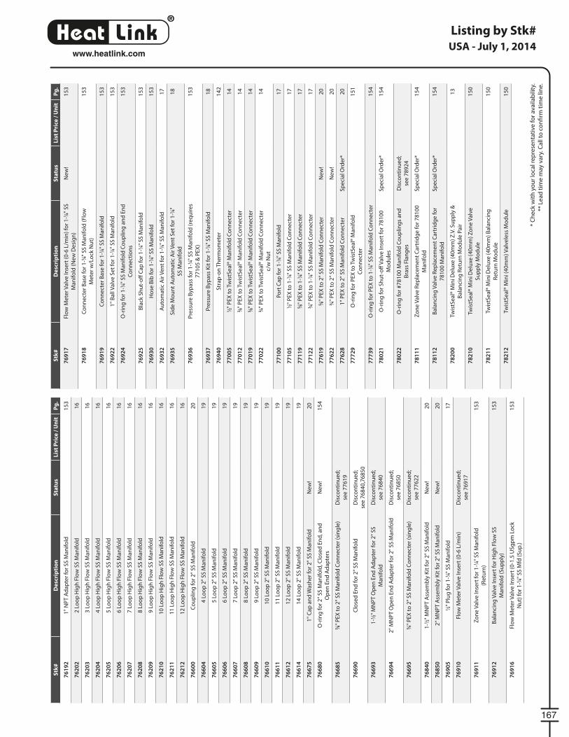
®
LinkHeat
167
www.heatlink.com
Listing by Stk#
* C
he
ck w
ith
yo
ur
loca
l re
pre
sen
tati
ve f
or
ava
ilab
ility
.
** L
ea
d t
ime
may
va
ry. C
all
to c
on
fi rm
tim
e li
ne
.
USA - July 1, 2014S
tk#
De
scri
pti
on
Sta
tus
Lis
t P
rice
/ U
nit
Pg
.
76
19
21
" N
PT
Ad
ap
ter
for
SS
Ma
nif
old
15
3
76
20
22
Lo
op
Hig
h F
low
SS
Ma
nif
old
16
76
20
33
Lo
op
Hig
h F
low
SS
Ma
nif
old
16
76
20
44
Lo
op
Hig
h F
low
SS
Ma
nif
old
16
76
20
55
Lo
op
Hig
h F
low
SS
Ma
nif
old
16
76
20
66
Lo
op
Hig
h F
low
SS
Ma
nif
old
16
76
20
77
Lo
op
Hig
h F
low
SS
Ma
nif
old
16
76
20
88
Lo
op
Hig
h F
low
SS
Ma
nif
old
16
76
20
99
Lo
op
Hig
h F
low
SS
Ma
nif
old
16
76
21
01
0 L
oo
p H
igh
Flo
w S
S M
an
ifo
ld1
6
76
21
11
1 L
oo
p H
igh
Flo
w S
S M
an
ifo
ld1
6
76
21
21
2 L
oo
p H
igh
Flo
w S
S M
an
ifo
ld1
6
76
60
0C
ou
plin
g f
or
2"
SS
Ma
nif
old
20
76
60
44
Lo
op
2"
SS
Ma
nif
old
19
76
60
55
Lo
op
2"
SS
Ma
nif
old
19
76
60
66
Lo
op
2"
SS
Ma
nif
old
19
76
60
77
Lo
op
2"
SS
Ma
nif
old
19
76
60
88
Lo
op
2"
SS
Ma
nif
old
19
76
60
99
Lo
op
2"
SS
Ma
nif
old
19
76
61
01
0 L
oo
p 2
" S
S M
an
ifo
ld1
9
76
61
11
1 L
oo
p 2
" S
S M
an
ifo
ld1
9
76
61
21
2 L
oo
p 2
" S
S M
an
ifo
ld1
9
76
61
41
4 L
oo
p 2
" S
S M
an
ifo
ld1
9
76
67
51
" C
ap
an
d W
ash
er
for
2"
SS
Ma
nif
old
Ne
w!
20
76
68
0O
-rin
g f
or
2"
SS
Ma
nif
old
, Clo
sed
En
d, a
nd
Op
en
En
d A
da
pte
rs
Ne
w!
15
4
76
68
55⁄8"
PE
X t
o 2
" S
S M
an
ifo
ld C
on
ne
cte
r (s
ing
le)
Dis
con
tin
ue
d;
see
77
61
9
76
69
0C
lose
d E
nd
fo
r 2
" S
S M
an
ifo
ldD
isco
nti
nu
ed
;
see
76
84
0,7
68
50
76
69
31
-1⁄2"
MN
PT
Op
en
En
d A
da
pte
r fo
r 2
" S
S
Ma
nif
old
Dis
con
tin
ue
d;
see
76
84
0
76
69
42
" M
NP
T O
pe
n E
nd
Ad
ap
ter
for
2"
SS
Ma
nif
old
Dis
con
tin
ue
d;
see
76
85
0
76
69
53⁄4"
PE
X t
o 2
" S
S M
an
ifo
ld C
on
ne
cte
r (s
ing
le)
Dis
con
tin
ue
d;
see
77
62
2
76
84
01
-1⁄2"
MN
PT
Ass
em
bly
Kit
fo
r 2
" S
S M
an
ifo
ldN
ew
!2
0
76
85
02
" M
NP
T A
sse
mb
ly K
it f
or
2"
SS
Ma
nif
old
Ne
w!
20
76
90
51⁄2"
Plu
g f
or
1-1
⁄4" S
S M
an
ifo
ld1
7
76
91
0Fl
ow
Me
ter
Va
lve
Inse
rt (
0-6
L/m
in)
Dis
con
tin
ue
d;
see
76
91
7
76
91
1Z
on
e V
alv
e In
sert
fo
r 1
-1⁄4"
SS
Ma
nif
old
(Re
turn
)
15
3
76
91
2B
ala
nci
ng
Va
lve
Inse
rt f
or
Hig
h F
low
SS
Ma
nif
old
(S
up
ply
)
15
3
76
91
6Fl
ow
Me
ter
Va
lve
Inse
rt (
0-1
.5 U
Sg
pm
Lo
ck
Nu
t) f
or
1-1
⁄4" S
S M
fd (
Su
p.)
15
3
Stk
#D
esc
rip
tio
nS
tatu
sL
ist
Pri
ce /
Un
itP
g.
76
91
7Fl
ow
Me
ter
Va
lve
Inse
rt (
0-6
L/m
in)
for
1-1
⁄4" S
S
Ma
nif
old
(N
ew
De
sig
n)
Ne
w!
15
3
76
91
8C
on
ne
cte
r B
ase
fo
r 1
-1⁄4"
SS
Ma
nif
old
(Fl
ow
Me
ter
w/L
ock
Nu
t)
15
3
76
91
9C
on
ne
cte
r B
ase
fo
r 1
-1⁄4"
SS
Ma
nif
old
15
3
76
92
21
" B
all
Va
lve
Se
t fo
r 1
-1⁄4"
SS
Ma
nif
old
15
3
76
92
4O
-rin
g f
or
1-1
⁄4" S
S M
an
ifo
ld C
ou
plin
g a
nd
En
d
Co
nn
ect
ion
s
15
3
76
92
5B
lack
Sh
ut-
off
Ca
p f
or
1-1
⁄4" S
S M
an
ifo
ld1
53
76
93
0H
ose
Bib
fo
r 1
-1⁄4"
SS
Ma
nif
old
15
3
76
93
2A
uto
ma
tic
Air
Ve
nt
for
1-1
⁄4" S
S M
an
ifo
ld1
7
76
93
5S
ide
Mo
un
t A
uto
ma
tic
Air
Ve
nt
Se
t fo
r 1
-1⁄4"
SS
Ma
nif
old
18
76
93
6P
ress
ure
Byp
ass
fo
r 1
-1⁄4"
SS
Ma
nif
old
(re
qu
ire
s
77
10
5 &
PE
X)
15
3
76
93
7P
ress
ure
Byp
ass
Kit
fo
r 1
-1⁄4"
SS
Ma
nif
old
18
76
94
0S
tra
p-o
n T
he
rmo
me
ter
14
2
77
00
51⁄2"
PE
X t
o T
wis
tSe
al®
Ma
nif
old
Co
nn
ect
er
14
77
01
23⁄8"
PE
X t
o T
wis
tSe
al®
Ma
nif
old
Co
nn
ect
er
14
77
01
95⁄8"
PE
X t
o T
wis
tSe
al®
Ma
nif
old
Co
nn
ect
er
14
77
02
23⁄4"
PE
X t
o T
wis
tSe
al®
Ma
nif
old
Co
nn
ect
er
c/w
Nu
t
14
77
10
0P
ort
Ca
p f
or
1-1
⁄4" S
S M
an
ifo
ld1
7
77
10
51⁄2"
PE
X t
o 1
-1⁄4"
SS
Ma
nif
old
Co
nn
ect
er
17
77
11
95⁄8"
PE
X t
o 1
-1⁄4"
SS
Ma
nif
old
Co
nn
ect
er
17
77
12
23⁄4"
PE
X t
o 1
-1⁄4"
SS
Ma
nif
old
Co
nn
ect
er
17
77
61
95⁄8"
PE
X t
o 2
" S
S M
an
ifo
ld C
on
ne
cte
rN
ew
!2
0
77
62
23⁄4"
PE
X t
o 2
" S
S M
an
ifo
ld C
on
ne
cte
rN
ew
!2
0
77
62
81
" P
EX
to
2"
SS
Ma
nif
old
Co
nn
ect
er
Sp
eci
al O
rde
r*2
0
77
72
9O
-rin
g f
or
PE
X t
o T
wis
tSe
al®
Ma
nif
old
Co
nn
ect
er
15
1
77
73
9O
-rin
g f
or
PE
X t
o 1
-1⁄4"
SS
Ma
nif
old
Co
nn
ect
er
15
4
78
02
1O
-rin
g f
or
Sh
ut-
off
Va
lve
Inse
rt f
or
78
10
0
Mo
du
les
Sp
eci
al O
rde
r*1
54
78
02
2O
-rin
g f
or
#7
81
00
Ma
nif
old
Co
up
ling
s a
nd
Bra
ss F
lan
ge
s
Dis
con
tin
ue
d;
see
78
92
4
78
11
1Z
on
e V
alv
e R
ep
lace
me
nt
Ca
rtri
dg
e f
or
78
10
0
Ma
nif
old
Sp
eci
al O
rde
r*1
54
78
11
2B
ala
nci
ng
Va
lve
Re
pla
cem
en
t C
art
rid
ge
fo
r
78
10
0 M
an
ifo
ld
Sp
eci
al O
rde
r*1
54
78
20
0Tw
istS
ea
l® M
ini D
elu
xe (
40
mm
) Z
.V. S
up
ply
&
Ba
lan
cin
g R
etu
rn M
od
ule
Pa
ir
13
78
21
0Tw
istS
ea
l® M
ini D
elu
xe (
40
mm
) Z
on
e V
alv
e
Su
pp
ly M
od
ule
15
0
78
21
1Tw
istS
ea
l® M
ini D
elu
xe (
40
mm
) B
ala
nci
ng
Re
turn
Mo
du
le
15
0
78
21
2Tw
istS
ea
l® M
ini (
40
mm
) Va
lve
less
Mo
du
le1
50
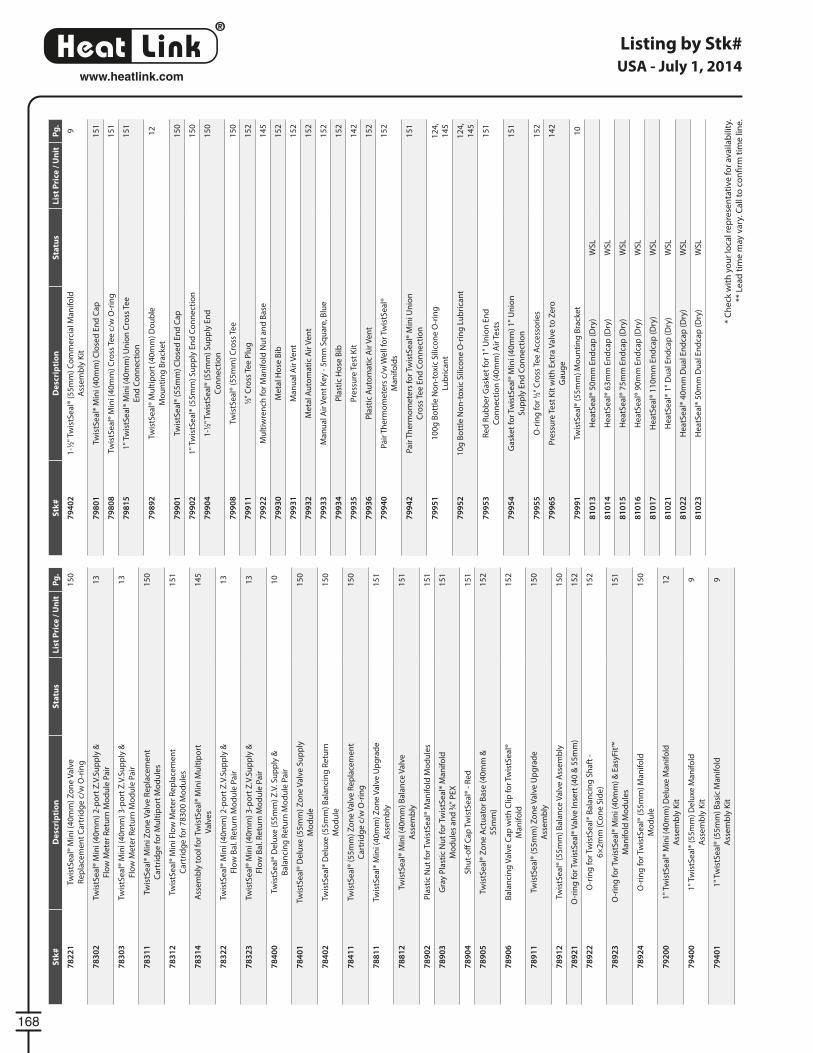
®
LinkHeat
168
www.heatlink.com
Listing by Stk#
* C
he
ck w
ith
yo
ur
loca
l re
pre
sen
tati
ve f
or
ava
ilab
ility
.
** L
ea
d t
ime
may
va
ry. C
all
to c
on
fi rm
tim
e li
ne
.
USA - July 1, 2014S
tk#
De
scri
pti
on
Sta
tus
Lis
t P
rice
/ U
nit
Pg
.
78
22
1Tw
istS
ea
l® M
ini (
40
mm
) Z
on
e V
alv
e
Re
pla
cem
en
t C
art
rid
ge
c/w
O-r
ing
15
0
78
30
2Tw
istS
ea
l® M
ini (
40
mm
) 2
-po
rt Z
.V.S
up
ply
&
Flo
w M
ete
r R
etu
rn M
od
ule
Pa
ir
13
78
30
3Tw
istS
ea
l® M
ini (
40
mm
) 3
-po
rt Z
.V.S
up
ply
&
Flo
w M
ete
r R
etu
rn M
od
ule
Pa
ir
13
78
31
1Tw
istS
ea
l® M
ini Z
on
e V
alv
e R
ep
lace
me
nt
Ca
rtri
dg
e f
or
Mu
ltip
ort
Mo
du
les
15
0
78
31
2Tw
istS
ea
l® M
ini F
low
Me
ter
Re
pla
cem
en
t
Ca
rtri
dg
e f
or
78
30
0 M
od
ule
s
15
1
78
31
4A
sse
mb
ly t
oo
l fo
r Tw
istS
ea
l® M
ini M
ult
ipo
rt
Va
lve
s
14
5
78
32
2Tw
istS
ea
l® M
ini (
40
mm
) 2
-po
rt Z
.V.S
up
ply
&
Flo
w B
al.
Re
turn
Mo
du
le P
air
13
78
32
3Tw
istS
ea
l® M
ini (
40
mm
) 3
-po
rt Z
.V.S
up
ply
&
Flo
w B
al.
Re
turn
Mo
du
le P
air
13
78
40
0Tw
istS
ea
l® D
elu
xe (
55
mm
) Z
.V. S
up
ply
&
Ba
lan
cin
g R
etu
rn M
od
ule
Pa
ir
10
78
40
1Tw
istS
ea
l® D
elu
xe (
55
mm
) Z
on
e V
alv
e S
up
ply
Mo
du
le
15
0
78
40
2Tw
istS
ea
l® D
elu
xe (
55
mm
) B
ala
nci
ng
Re
turn
Mo
du
le
15
0
78
41
1Tw
istS
ea
l® (
55
mm
) Z
on
e V
alv
e R
ep
lace
me
nt
Ca
rtri
dg
e c
/w O
-rin
g
15
0
78
81
1Tw
istS
ea
l® M
ini (
40
mm
) Z
on
e V
alv
e U
pg
rad
e
Ass
em
bly
15
1
78
81
2Tw
istS
ea
l® M
ini (
40
mm
) B
ala
nce
Va
lve
Ass
em
bly
15
1
78
90
2P
last
ic N
ut
for
Twis
tSe
al®
Ma
nif
old
Mo
du
les
15
1
78
90
3G
ray
Pla
stic
Nu
t fo
r Tw
istS
ea
l® M
an
ifo
ld
Mo
du
les
an
d 3
⁄4" P
EX
15
1
78
90
4S
hu
t-o
ff C
ap
Tw
istS
ea
l® -
Re
d1
51
78
90
5Tw
istS
ea
l® Z
on
e A
ctu
ato
r B
ase
(4
0m
m &
55
mm
)
15
2
78
90
6B
ala
nci
ng
Va
lve
Ca
p w
ith
Clip
fo
r Tw
istS
ea
l®
Ma
nif
old
15
2
78
91
1Tw
istS
ea
l® (
55
mm
) Z
on
e V
alv
e U
pg
rad
e
Ass
em
bly
15
0
78
91
2Tw
istS
ea
l® (
55
mm
) B
ala
nce
Va
lve
Ass
em
bly
15
0
78
92
1O
-rin
g f
or
Twis
tSe
al®
Va
lve
Inse
rt (
40
& 5
5m
m)
15
2
78
92
2O
-rin
g f
or
Twis
tSe
al®
Ba
lan
cin
g S
ha
ft -
6×
2m
m (
Co
ne
Sid
e)
15
2
78
92
3O
-rin
g f
or
Twis
tSe
al®
Min
i (4
0m
m)
& E
asy
Fit™
Ma
nif
old
Mo
du
les
15
1
78
92
4O
-rin
g f
or
Twis
tSe
al®
(5
5m
m)
Ma
nif
old
Mo
du
le
15
0
79
20
01
" Tw
istS
ea
l® M
ini (
40
mm
) D
elu
xe M
an
ifo
ld
Ass
em
bly
Kit
12
79
40
01
" Tw
istS
ea
l® (
55
mm
) D
elu
xe M
an
ifo
ld
Ass
em
bly
Kit
9
79
40
11
" Tw
istS
ea
l® (
55
mm
) B
asi
c M
an
ifo
ld
Ass
em
bly
Kit
9
Stk
#D
esc
rip
tio
nS
tatu
sL
ist
Pri
ce /
Un
itP
g.
79
40
21
-1⁄2"
Tw
istS
ea
l® (
55
mm
) C
om
me
rcia
l Ma
nif
old
Ass
em
bly
Kit
9
79
80
1Tw
istS
ea
l® M
ini (
40
mm
) C
lose
d E
nd
Ca
p1
51
79
80
8Tw
istS
ea
l® M
ini (
40
mm
) C
ross
Te
e c
/w O
-rin
g1
51
79
81
51
" Tw
istS
ea
l® M
ini (
40
mm
) U
nio
n C
ross
Te
e
En
d C
on
ne
ctio
n
15
1
79
89
2Tw
istS
ea
l® M
ult
ipo
rt (
40
mm
) D
ou
ble
Mo
un
tin
g B
rack
et
12
79
90
1Tw
istS
ea
l® (
55
mm
) C
lose
d E
nd
Ca
p1
50
79
90
21
" Tw
istS
ea
l® (
55
mm
) S
up
ply
En
d C
on
ne
ctio
n1
50
79
90
41
-1⁄2"
Tw
istS
ea
l® (
55
mm
) S
up
ply
En
d
Co
nn
ect
ion
15
0
79
90
8Tw
istS
ea
l® (
55
mm
) C
ross
Te
e1
50
79
91
11⁄2"
Cro
ss T
ee
Plu
g1
52
79
92
2M
ult
iwre
nch
fo
r M
an
ifo
ld N
ut
an
d B
ase
14
5
79
93
0M
eta
l Ho
se B
ib1
52
79
93
1M
an
ua
l Air
Ve
nt
15
2
79
93
2M
eta
l Au
tom
ati
c A
ir V
en
t1
52
79
93
3M
an
ua
l Air
Ve
nt
Ke
y -
5m
m S
qu
are
, Blu
e1
52
79
93
4P
last
ic H
ose
Bib
15
2
79
93
5P
ress
ure
Te
st K
it1
42
79
93
6P
last
ic A
uto
ma
tic
Air
Ve
nt
15
2
79
94
0P
air
Th
erm
om
ete
rs c
/w W
ell
for
Twis
tSe
al®
Ma
nif
old
s
15
2
79
94
2P
air
Th
erm
om
ete
rs f
or
Twis
tSe
al®
Min
i Un
ion
Cro
ss T
ee
En
d C
on
ne
ctio
n
15
1
79
95
11
00
g B
ott
le N
on
-to
xic
Sili
con
e O
-rin
g
Lub
rica
nt
12
4,
14
5
79
95
21
0g
Bo
ttle
No
n-t
oxi
c S
ilico
ne
O-r
ing
Lu
bri
can
t1
24
,
14
5
79
95
3R
ed
Ru
bb
er
Ga
ske
t fo
r 1
" U
nio
n E
nd
Co
nn
ect
ion
(4
0m
m)
Air
Te
sts
15
1
79
95
4G
ask
et
for
Twis
tSe
al®
Min
i (4
0m
m)
1"
Un
ion
Su
pp
ly E
nd
Co
nn
ect
ion
15
1
79
95
5O
-rin
g f
or
1⁄2"
Cro
ss T
ee
Acc
ess
ori
es
15
2
79
96
5P
ress
ure
Te
st K
it w
ith
Ext
ra V
alv
e t
o Z
ero
Ga
ug
e
14
2
79
99
1Tw
istS
ea
l® (
55
mm
) M
ou
nti
ng
Bra
cke
t1
0
81
01
3H
ea
tSe
al®
50
mm
En
dca
p (
Dry
)W
SL
81
01
4H
ea
tSe
al®
63
mm
En
dca
p (
Dry
)W
SL
81
01
5H
ea
tSe
al®
75
mm
En
dca
p (
Dry
)W
SL
81
01
6H
ea
tSe
al®
90
mm
En
dca
p (
Dry
)W
SL
81
01
7H
ea
tSe
al®
11
0m
m E
nd
cap
(D
ry)
WS
L
81
02
1H
ea
tSe
al®
1"
Du
al E
nd
cap
(D
ry)
WS
L
81
02
2H
ea
tSe
al®
40
mm
Du
al E
nd
cap
(D
ry)
WS
L
81
02
3H
ea
tSe
al®
50
mm
Du
al E
nd
cap
(D
ry)
WS
L
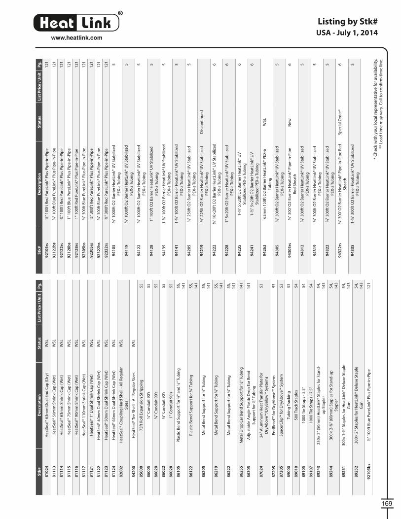
®
LinkHeat
169
www.heatlink.com
Listing by Stk#
* C
he
ck w
ith
yo
ur
loca
l re
pre
sen
tati
ve f
or
ava
ilab
ility
.
** L
ea
d t
ime
may
va
ry. C
all
to c
on
fi rm
tim
e li
ne
.
USA - July 1, 2014S
tk#
De
scri
pti
on
Sta
tus
Lis
t P
rice
/ U
nit
Pg
.
81
02
4H
ea
tSe
al®
63
mm
Du
al E
nd
Ca
p (
Dry
)W
SL
81
11
3H
ea
tSe
al®
50
mm
Sh
rin
k C
ap
(W
et)
WS
L
81
11
4H
ea
tSe
al®
63
mm
Sh
rin
k C
ap
(W
et)
WS
L
81
11
5H
ea
tSe
al®
75
mm
Sh
rin
k C
ap
(W
et)
WS
L
81
11
6H
ea
tSe
al®
90
mm
Sh
rin
k C
ap
(W
et)
WS
L
81
11
7H
ea
tSe
al®
11
0m
m S
hri
nk
Ca
p (
We
t)W
SL
81
12
1H
ea
tSe
al®
1"
Du
al S
hri
nk
Ca
p (
We
t)W
SL
81
12
2H
ea
tSe
al®
40
mm
Du
al S
hri
nk
Ca
p (
We
t)W
SL
81
12
3H
ea
tSe
al®
50
mm
Du
al S
hri
nk
Ca
p (
We
t)W
SL
81
12
4H
ea
tSe
al®
63
mm
Du
al S
hri
nk
Ca
p (
We
t)W
SL
82
00
2H
ea
tSe
al®
Co
up
ling
Ha
rd S
he
ll -
All
Re
gu
lar
Siz
es
WS
L
84
20
0H
ea
tSe
al®
Te
e S
he
ll -
All
Re
gu
lar
Siz
es
WS
L
85
00
07
5ft
Ro
ll E
xpa
nsi
on
Str
ipp
ing
55
86
00
51⁄2"
Co
nd
uit
90
's5
5
86
02
05⁄8"
Co
nd
uit
90
's5
5
86
02
23⁄4"
Co
nd
uit
90
's5
5
86
02
81
" C
on
du
it 9
0's
55
86
10
5P
last
ic B
en
d S
up
po
rt f
or
3⁄8"
an
d 1
⁄2" T
ub
ing
55
,
14
1
86
12
2P
last
ic B
en
d S
up
po
rt f
or
3⁄4"
Tu
bin
g5
5,
14
1
86
20
5M
eta
l Be
nd
Su
pp
ort
fo
r 1⁄2"
Tu
bin
g5
5,
14
1
86
21
9M
eta
l Be
nd
Su
pp
ort
fo
r 5⁄8"
Tu
bin
g5
5,
14
1
86
22
2M
eta
l Be
nd
Su
pp
ort
fo
r 3⁄4"
Tu
bin
g5
5,
14
1
86
25
5M
eta
l Dro
p E
ar
Be
nd
Su
pp
ort
fo
r 1⁄2"
Tu
bin
g1
41
86
30
5A
dju
sta
ble
An
gle
Pla
stic
Dro
p E
ar
Be
nd
Su
pp
ort
fo
r 1⁄2"
Tu
bin
g
14
1
87
02
42
4"
Alu
min
um
He
at
Tra
nsf
er
Pla
te f
or
Dry
Ab
ove
™/D
ryB
elo
w™
Sys
tem
s
53
87
20
5E
nd
Be
nd
™ f
or
Dry
Ab
ove
™ S
yste
m5
3
87
30
5S
pa
cerC
lip™
fo
r D
ryA
bo
ve™
Sys
tem
53
89
00
0Tu
bin
g T
rack
ing
53
89
01
05
00
Tra
ck S
tap
les
54
89
10
51
00
0 T
ie S
tra
ps
- 5
.5"
54
89
10
71
00
0 T
ie S
tra
ps
- 7
.5"
54
89
24
32
50
× 2
" (5
0m
m)
He
atL
ink®
Sta
ple
s fo
r S
tan
d-
up
Sta
ple
r
54
,
14
3
89
24
43
00
× 2
-3⁄8"
(6
0m
m)
Sta
ple
s fo
r S
tan
d-u
p
Sta
ple
r
54
,
14
3
89
25
13
00
× 1
-1⁄2"
Sta
ple
s fo
r H
ea
tLin
k® D
elu
xe S
tap
le
Gu
n
54
,
14
3
89
25
23
00
× 2
" S
tap
les
for
He
atL
ink®
De
luxe
Sta
ple
Gu
n
54
,
14
3
92
10
5b
s1⁄2"
10
0ft
Blu
e P
ure
Lin
k® P
lus
Pip
e-i
n-P
ipe
12
1
Stk
#D
esc
rip
tio
nS
tatu
sL
ist
Pri
ce /
Un
itP
g.
92
10
5rs
1⁄2"
10
0ft
Re
d P
ure
Lin
k® P
lus
Pip
e-i
n-P
ipe
12
1
92
12
2b
s3⁄4"
10
0ft
Blu
e P
ure
Lin
k® P
lus
Pip
e-i
n-P
ipe
12
1
92
12
2rs
3⁄4"
10
0ft
Re
d P
ure
Lin
k® P
lus
Pip
e-i
n-P
ipe
12
1
92
12
8b
s1
" 1
00
ft B
lue
Pu
reLi
nk®
Plu
s P
ipe
-in
-Pip
e1
21
92
12
8rs
1"
10
0ft
Re
d P
ure
Lin
k® P
lus
Pip
e-i
n-P
ipe
12
1
92
30
5b
s1⁄2"
30
0ft
Blu
e P
ure
Lin
k® P
lus
Pip
e-i
n-P
ipe
12
1
92
30
5rs
1⁄2"
30
0ft
Re
d P
ure
Lin
k® P
lus
Pip
e-i
n-P
ipe
12
1
92
32
2b
s3⁄4"
30
0ft
Blu
e P
ure
Lin
k® P
lus
Pip
e-i
n-P
ipe
12
1
92
32
2rs
3⁄4"
30
0ft
Re
d P
ure
Lin
k® P
lus
Pip
e-i
n-P
ipe
12
1
94
10
51⁄2"
10
00
ft O
2 B
arr
ier
He
atL
ink®
UV
Sta
bili
zed
PE
X-a
Tu
bin
g
5
94
11
95⁄8"
10
00
ft O
2 B
arr
ier
He
atL
ink®
UV
Sta
bili
zed
PE
X-a
Tu
bin
g
5
94
12
23⁄4"
10
00
ft O
2 B
arr
ier
He
atL
ink®
UV
Sta
bili
zed
PE
X-a
Tu
bin
g
5
94
12
81
" 1
00
ft O
2 B
arr
ier
He
atL
ink®
UV
Sta
bili
zed
PE
X-a
Tu
bin
g
5
94
13
51
-1⁄4"
10
0ft
O2
Ba
rrie
r H
ea
tLin
k® U
V S
tab
ilize
d
PE
X-a
Tu
bin
g
5
94
14
11
-1⁄2"
10
0ft
O2
Ba
rrie
r H
ea
tLin
k® U
V S
tab
ilize
d
PE
X-a
Tu
bin
g
5
94
20
51⁄2"
25
0ft
O2
Ba
rrie
r H
ea
tLin
k® U
V S
tab
ilize
d
PE
X-a
Tu
bin
g
5
94
21
95⁄8"
22
5ft
O2
Ba
rrie
r H
ea
tLin
k® U
V S
tab
ilize
d
PE
X-a
Tu
bin
g
Dis
con
tin
ue
d
94
22
23⁄4"
10
×2
0ft
O2
Ba
rrie
r H
ea
tLin
k® U
V S
tab
ilize
d
PE
X-a
Tu
bin
g
6
94
22
81
" 5
×2
0ft
O2
Ba
rrie
r H
ea
tLin
k® U
V S
tab
ilize
d
PE
X-a
Tu
bin
g
6
94
23
51
-1⁄4"
5×
20
ft O
2 B
arr
ier
He
atL
ink®
UV
Sta
bili
zed
PE
X-a
Tu
bin
g
6
94
24
11
-1⁄2"
5×
20
ft O
2 B
arr
ier
He
atL
ink®
UV
Sta
bili
zed
PE
X-a
Tu
bin
g
6
94
26
36
3m
m 1
50
ft O
2 B
arr
ier
He
atL
ink®
PE
X-a
Tub
ing
WS
L
94
30
51⁄2"
30
0ft
O2
Ba
rrie
r H
ea
tLin
k® U
V S
tab
ilize
d
PE
X-a
Tu
bin
g
5
94
30
5rs
1⁄2"
30
0' O
2 B
arr
ier
He
atL
ink®
Pip
e-i
n-P
ipe
Re
d S
he
ath
Ne
w!
6
94
31
23⁄8"
30
0ft
O2
Ba
rrie
r H
ea
tLin
k® U
V S
tab
ilize
d
PE
X-a
Tu
bin
g
5
94
31
95⁄8"
30
0ft
O2
Ba
rrie
r H
ea
tLin
k® U
V S
tab
ilize
d
PE
X-a
Tu
bin
g
5
94
32
23⁄4"
30
0ft
O2
Ba
rrie
r H
ea
tLin
k® U
V S
tab
ilize
d
PE
X-a
Tu
bin
g
5
94
32
2rs
3⁄4"
30
0' O
2 B
arr
ier
He
atL
ink®
Pip
e-i
n-P
ipe
Re
d
Sh
ea
th
Sp
eci
al O
rde
r*6
94
33
51
-1⁄4"
30
0ft
O2
Ba
rrie
r H
ea
tLin
k® U
V S
tab
ilize
d
PE
X-a
Tu
bin
g
5
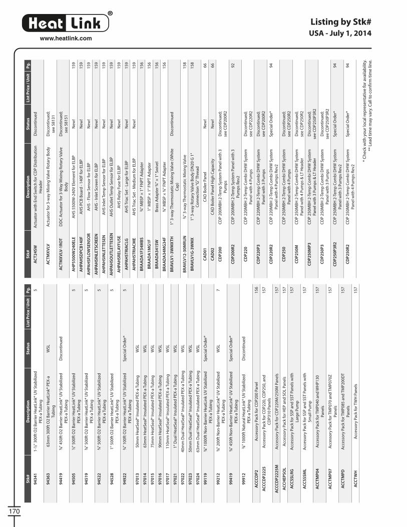
®
LinkHeat
170
www.heatlink.com
Listing by Stk#
* C
he
ck w
ith
yo
ur
loca
l re
pre
sen
tati
ve f
or
ava
ilab
ility
.
** L
ea
d t
ime
may
va
ry. C
all
to c
on
fi rm
tim
e li
ne
.
USA - July 1, 2014S
tk#
De
scri
pti
on
Sta
tus
Lis
t P
rice
/ U
nit
Pg
.
94
34
11
-1⁄2"
30
0ft
O2
Ba
rrie
r H
ea
tLin
k® U
V S
tab
ilize
d
PE
X-a
Tu
bin
g
5
94
36
36
3m
m 3
00
ft O
2 B
arr
ier
He
atL
ink®
PE
X-a
Tub
ing
WS
L
94
41
95⁄8"
45
0ft
O2
Ba
rrie
r H
ea
tLin
k® U
V S
tab
ilize
d
PE
X-a
Tu
bin
g
Dis
con
tin
ue
d
94
50
51⁄2"
50
0ft
O2
Ba
rrie
r H
ea
tLin
k® U
V S
tab
ilize
d
PE
X-a
Tu
bin
g
5
94
51
95⁄8"
50
0ft
O2
Ba
rrie
r H
ea
tLin
k® U
V S
tab
ilize
d
PE
X-a
Tu
bin
g
5
94
52
23⁄4"
50
0ft
O2
Ba
rrie
r H
ea
tLin
k® U
V S
tab
ilize
d
PE
X-a
Tu
bin
g
5
94
52
81
" 5
00
ft O
2 B
arr
ier
He
atL
ink®
UV
Sta
bili
zed
PE
X-a
Tu
bin
g
5
94
92
23⁄4"
10
0ft
O2
Ba
rrie
r H
ea
tLin
k® U
V S
tab
ilize
d
PE
X-a
Tu
bin
g
Sp
eci
al O
rde
r*5
97
01
35
0m
m H
ea
tSe
al®
Insu
late
d P
EX
-a T
ub
ing
WS
L
97
01
46
3m
m H
ea
tSe
al®
Insu
late
d P
EX
-a T
ub
ing
WS
L
97
01
57
5m
m H
ea
tSe
al®
Insu
late
d P
EX
-a T
ub
ing
WS
L
97
01
69
0m
m H
ea
tSe
al®
Insu
late
d P
EX
-a T
ub
ing
WS
L
97
01
71
10
mm
He
atS
ea
l® In
sula
ted
PE
X-a
Tu
bin
gW
SL
97
02
11
" D
ua
l He
atS
ea
l® In
sula
ted
PE
X-a
Tu
bin
gW
SL
97
02
24
0m
m D
ua
l He
atS
ea
l® In
sula
ted
PE
X-a
Tu
bin
gW
SL
97
02
35
0m
m D
ua
l He
atS
ea
l® In
sula
ted
PE
X-a
Tu
bin
gW
SL
97
02
46
3m
m D
ua
l He
atS
ea
l® In
sula
ted
PE
X-a
Tu
bin
gW
SL
99
11
95⁄8"
10
00
ft N
on
-Ba
rrie
r H
ea
tLin
k U
V S
tab
ilize
d
PE
X-a
Tu
bin
g
Sp
eci
al O
rde
r*
99
21
23⁄8"
20
0ft
No
n-B
arr
ier
He
atL
ink®
UV
Sta
bili
zed
PE
X-a
Tu
bin
g
WS
L7
99
41
95⁄8"
45
0ft
No
n-B
arr
ier
He
atL
ink®
UV
Sta
bili
zed
PE
X-a
Tu
bin
g
Sp
eci
al O
rde
r*
99
91
23⁄8"
10
00
ft N
atu
ral H
ea
tLin
k® U
V S
tab
ilize
d
PE
X-a
Tu
bin
g
Dis
con
tin
ue
d
AC
CC
DP
2A
cce
sso
ry P
ack
fo
r C
DP
20
0 P
an
el
15
6
AC
CC
DP
22
25
Acc
ess
ory
Pa
ck f
or
CD
P2
20
, CD
P2
50
, an
d
CD
P3
10
Pa
ne
ls
15
7
AC
CC
DP
22
25
MA
cce
sso
ry P
ack
fo
r C
DP
22
0M
/25
0M
Pa
ne
ls1
57
AC
CH
EP
SO
LA
cce
sso
ry P
ack
fo
r H
EP
an
d S
OL
Pa
ne
ls1
57
AC
CS
SL
RG
Acc
ess
ory
Pa
ck f
or
SS
P a
nd
SS
T P
an
els
wit
h
Larg
e P
um
p
15
7
AC
CS
SS
ML
Acc
ess
ory
Pa
ck f
or
SS
P a
nd
SS
T P
an
els
wit
h
Sm
all
Pu
mp
15
7
AC
CT
MP
04
Acc
ess
ory
Pa
ck f
or
TM
P0
40
an
d W
HP
13
0
Pa
ne
ls
15
7
AC
CT
MP
07
Acc
ess
ory
Pa
ck f
or
TM
P0
70
an
d T
MP
07
0Z
Pa
ne
ls
15
7
AC
CT
MP
DA
cce
sso
ry P
ack
fo
r T
MP
08
5 a
nd
TM
P2
00
DT
Pa
ne
ls
15
7
AC
CT
WH
Acc
ess
ory
Pa
ck f
or
TW
H P
an
els
15
7
Stk
#D
esc
rip
tio
nS
tatu
sL
ist
Pri
ce /
Un
itP
g.
AC
T2
4S
WA
ctu
ato
r w
ith
En
d S
wit
ch f
or
CD
P D
istr
ibu
tio
n
He
ad
er
Dis
con
tin
ue
d
AC
TM
XV
LVA
ctu
ato
r fo
r 3
-way
Mix
ing
Va
lve
Ro
tary
Bo
dy
Dis
con
tin
ue
d;
see
58
13
1
AC
TM
XV
LV-1
RO
TD
DC
Act
ua
tor
for
3-W
ay M
ixin
g R
ota
ry V
alv
e
Bo
dy
Dis
con
tin
ue
d;
see
58
15
1
AH
P5
50
0W
24
0E
LE
AH
S 5
50
0W
-24
0V
Ele
me
nt
for
ELB
PN
ew
!1
59
AH
PA
HS
DP
CB
14
0F
AH
S P
CB
Bo
ard
- 1
40
F f
or
ELB
PN
ew
!1
59
AH
PA
HS
FLO
WS
EN
SO
RA
HS
- F
low
Se
nso
r fo
r E
LBP
Ne
w!
15
9
AH
PA
HS
INL
ET
SC
RE
EN
AH
S -
Inle
t S
cre
en
fo
r E
LBP
Ne
w!
15
9
AH
PA
HS
INL
ET
TE
SE
NA
HS
Inle
t Te
mp
Se
nso
r fo
r E
LBP
Ne
w!
15
9
AH
PA
HS
OU
TL
ET
TE
SE
NA
HS
Ou
tle
t Te
mp
Se
nso
r fo
r E
LBP
Ne
w!
15
9
AH
PA
HS
RE
LA
YF
US
EA
HS
Re
lay
Fuse
fo
r E
LBP
Ne
w!
15
9
AH
PA
HS
TR
IAC
LGA
HS
Tri
ac
Se
t -
Larg
e f
or
ELB
PN
ew
!1
59
AH
PA
HS
TR
IAC
ME
AH
S T
ria
c S
et
- M
ed
ium
fo
r E
LBP
Ne
w!
15
9
BR
AA
DA
1F
34
MB
S3⁄4"
MB
SP
× 1
" F
NP
T A
da
pte
r1
56
BR
AA
DA
1M
G1
F1
" M
BS
P ×
1"
FN
PT
Ad
ap
ter
15
6
BR
AA
DA
34
1S
WB
rass
Ad
ap
ter
3⁄4"
× 1
" S
wiv
el
15
6
BR
AA
DA
34
MG
34
F3⁄4"
MB
SP
× 3
⁄4" F
NP
T A
da
pte
r1
56
BR
AV
LV1
-3W
MX
TH
1"
3-w
ay T
he
rmo
sta
tic
Mix
ing
Va
lve
(W
hit
e
Ca
p)
Dis
con
tin
ue
d
BR
AV
LV1
2-3
0M
RU
N3⁄4"
3-w
ay T
he
rmo
sta
tic
Mix
ing
Va
lve
15
8
BR
AV
LV1
G-3
WM
X1
" 3
-way
Ro
tary
Va
lve
Bo
dy
DN
20
G 1
"
Co
nn
ect
ion
"G
" T
hre
ad
15
8
CA
D0
1C
AD
Bo
iler
Pa
ne
lN
ew
!6
6
CA
D0
2C
AD
Bo
iler
Pa
ne
l Hig
h C
ap
aci
tyN
ew
!6
6
CD
P2
00
CD
P 2
00
MB
H 2
-Te
mp
Sys
tem
Pa
ne
l wit
h 3
Pu
mp
s
Dis
con
tin
ue
d;
see
CD
P2
00
R2
CD
P2
00
R2
CD
P 2
00
MB
H 2
-Te
mp
Sys
tem
Pa
ne
l wit
h 3
Pu
mp
s R
ev
2
92
CD
P2
20
CD
P 2
20
MB
H 2
-Te
mp
Co
mb
i DH
W S
yste
m
Pa
ne
l wit
h 4
Pu
mp
s
Dis
con
tin
ue
d;
see
CD
P2
20
R2
CD
P2
20
P3
CD
P 2
20
MB
H 2
-Te
mp
Co
mb
i DH
W S
yste
m
Pa
ne
l wit
h 3
Pu
mp
s
Dis
con
tin
ue
d;
see
CD
P2
00
R2
CD
P2
20
R2
CD
P 2
20
MB
H 2
-Te
mp
Co
mb
i DH
W S
yste
m
Pa
ne
l wit
h 4
Pu
mp
s R
ev
2
Sp
eci
al O
rde
r*9
4
CD
P2
50
CD
P 2
50
MB
H 2
-Te
mp
Co
mb
i DH
W S
yste
m
Pa
ne
l wit
h 4
Pu
mp
s
Dis
con
tin
ue
d;
see
CD
P2
50
R2
CD
P2
50
MC
DP
25
0M
BH
2-T
em
p C
om
bi D
HW
Sys
tem
Pa
ne
l wit
h 4
Pu
mp
s &
LT
He
ad
er
Dis
con
tin
ue
d;
see
CD
P2
50
R2
CD
P2
50
MP
3C
DP
25
0M
BH
2-T
em
p C
om
bi D
HW
Sys
tem
Pa
ne
l wit
h 3
Pu
mp
s &
LT
He
ad
er
Dis
con
tin
ue
d;
see
CD
P2
50
P3
R2
CD
P2
50
P3
CD
P 2
50
MB
H 2
-Te
mp
Co
mb
i DH
W S
yste
m
Pa
ne
l wit
h 3
Pu
mp
s
Dis
con
tin
ue
d;
see
CD
P2
50
P3
R2
CD
P2
50
P3
R2
CD
P 2
50
MB
H 2
-Te
mp
Co
mb
i DH
W S
yste
m
Pa
ne
l wit
h 3
Pu
mp
s R
ev
2
Sp
eci
al O
rde
r*9
4
CD
P2
50
R2
CD
P 2
50
MB
H 2
-Te
mp
Co
mb
i DH
W S
yste
m
Pa
ne
l wit
h 4
Pu
mp
s R
ev
2
Sp
eci
al O
rde
r*9
4
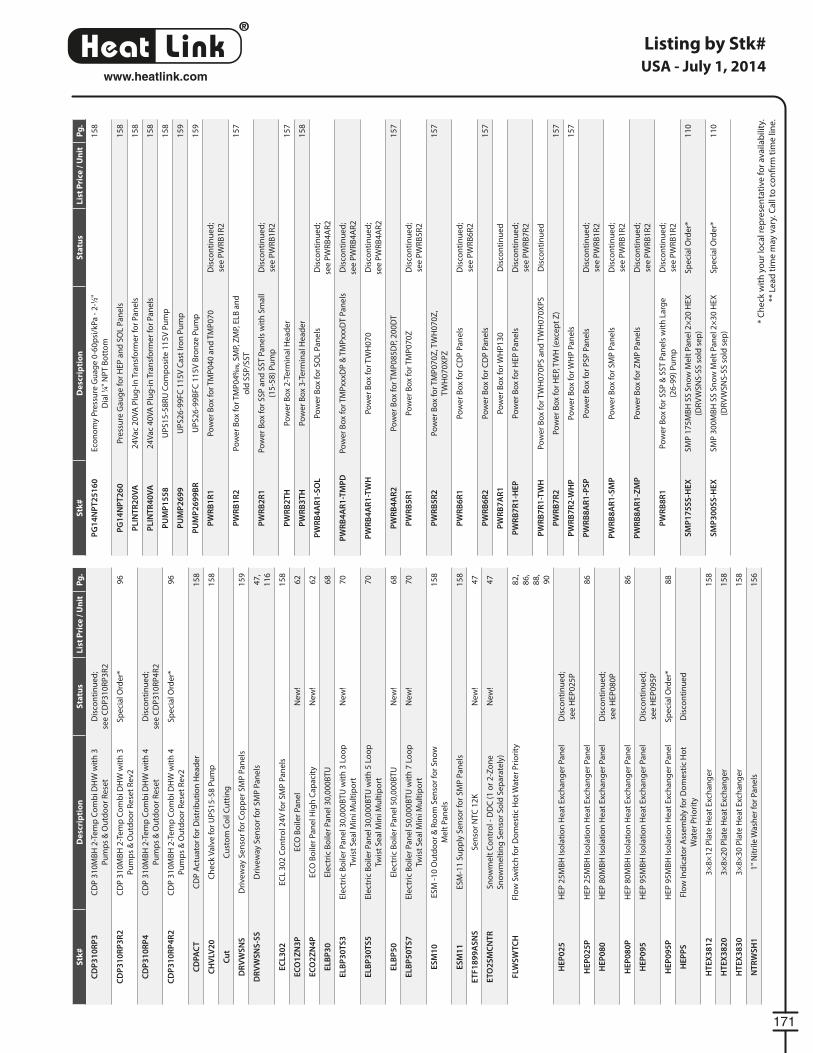
®
LinkHeat
171
www.heatlink.com
Listing by Stk#
* C
he
ck w
ith
yo
ur
loca
l re
pre
sen
tati
ve f
or
ava
ilab
ility
.
** L
ea
d t
ime
may
va
ry. C
all
to c
on
fi rm
tim
e li
ne
.
USA - July 1, 2014S
tk#
De
scri
pti
on
Sta
tus
Lis
t P
rice
/ U
nit
Pg
.
CD
P3
10
RP
3C
DP
31
0M
BH
2-T
em
p C
om
bi D
HW
wit
h 3
Pu
mp
s &
Ou
tdo
or
Re
set
Dis
con
tin
ue
d;
see
CD
P3
10
RP
3R
2
CD
P3
10
RP
3R
2C
DP
31
0M
BH
2-T
em
p C
om
bi D
HW
wit
h 3
Pu
mp
s &
Ou
tdo
or
Re
set
Re
v2
Sp
eci
al O
rde
r*9
6
CD
P3
10
RP
4C
DP
31
0M
BH
2-T
em
p C
om
bi D
HW
wit
h 4
Pu
mp
s &
Ou
tdo
or
Re
set
Dis
con
tin
ue
d;
see
CD
P3
10
RP
4R
2
CD
P3
10
RP
4R
2C
DP
31
0M
BH
2-T
em
p C
om
bi D
HW
wit
h 4
Pu
mp
s &
Ou
tdo
or
Re
set
Re
v2
Sp
eci
al O
rde
r*9
6
CD
PA
CT
CD
P A
ctu
ato
r fo
r D
istr
ibu
tio
n H
ea
de
r1
58
CH
VLV
20
Ch
eck
Va
lve
fo
r U
PS
15
-58
Pu
mp
15
8
Cu
tC
ust
om
Co
il C
utt
ing
DR
VW
SN
SD
rive
way
Se
nso
r fo
r C
op
pe
r S
MP
Pa
ne
ls1
59
DR
VW
SN
S-S
SD
rive
way
Se
nso
r fo
r S
MP
Pa
ne
ls4
7,
11
6
EC
L3
02
EC
L 3
02
Co
ntr
ol 2
4V
fo
r S
MP
Pa
ne
ls1
58
EC
O1
ZN
3P
EC
O B
oile
r P
an
el
Ne
w!
62
EC
O2
ZN
4P
EC
O B
oile
r P
an
el H
igh
Ca
pa
city
Ne
w!
62
EL
BP
30
Ele
ctri
c B
oile
r P
an
el 3
0,0
00
BT
U6
8
EL
BP
30
TS
3E
lect
ric
Bo
iler
Pa
ne
l 30
,00
0B
TU
wit
h 3
Lo
op
Twis
t S
ea
l Min
i Mu
ltip
ort
Ne
w!
70
EL
BP
30
TS
5E
lect
ric
Bo
iler
Pa
ne
l 30
,00
0B
TU
wit
h 5
Lo
op
Twis
t S
ea
l Min
i Mu
ltip
ort
70
EL
BP
50
Ele
ctri
c B
oile
r P
an
el 5
0,0
00
BT
UN
ew
!6
8
EL
BP
50
TS
7E
lect
ric
Bo
iler
Pa
ne
l 50
,00
0B
TU
wit
h 7
Lo
op
Twis
t S
ea
l Min
i Mu
ltip
ort
Ne
w!
70
ES
M1
0E
SM
-1
0 O
utd
oo
r &
Ro
om
Se
nso
r fo
r S
no
w
Me
lt P
an
els
15
8
ES
M1
1E
SM
-11
Su
pp
ly S
en
sor
for
SM
P P
an
els
15
8
ET
F1
89
9A
SN
SS
en
sor
NTC
12
KN
ew
!4
7
ET
O2
SM
CN
TR
Sn
ow
me
lt C
on
tro
l - D
DC
(1
or
2-Z
on
e
Sn
ow
me
ltin
g S
en
sor
So
ld S
ep
ara
tely
)
Ne
w!
47
FLW
SW
TC
HFl
ow
Sw
itch
fo
r D
om
est
ic H
ot
Wat
er
Pri
ori
ty8
2,
86
,
88
,
90
HE
P0
25
HE
P 2
5M
BH
Iso
lati
on
He
at
Exc
ha
ng
er
Pa
ne
lD
isco
nti
nu
ed
;
see
HE
P0
25
P
HE
P0
25
PH
EP
25
MB
H Is
ola
tio
n H
ea
t E
xch
an
ge
r P
an
el
86
HE
P0
80
HE
P 8
0M
BH
Iso
lati
on
He
at
Exc
ha
ng
er
Pa
ne
lD
isco
nti
nu
ed
;
see
HE
P0
80
P
HE
P0
80
PH
EP
80
MB
H Is
ola
tio
n H
ea
t E
xch
an
ge
r P
an
el
86
HE
P0
95
HE
P 9
5M
BH
Iso
lati
on
He
at
Exc
ha
ng
er
Pa
ne
lD
isco
nti
nu
ed
;
see
HE
P0
95
P
HE
P0
95
PH
EP
95
MB
H Is
ola
tio
n H
ea
t E
xch
an
ge
r P
an
el
Sp
eci
al O
rde
r*8
8
HE
PP
SFl
ow
Ind
ica
tor
Ass
em
bly
fo
r D
om
est
ic H
ot
Wat
er
Pri
ori
ty
Dis
con
tin
ue
d
HT
EX
38
12
3×
8×
12
Pla
te H
ea
t E
xch
an
ge
r1
58
HT
EX
38
20
3×
8×
20
Pla
te H
ea
t E
xch
an
ge
r1
58
HT
EX
38
30
3×
8×
30
Pla
te H
ea
t E
xch
an
ge
r1
58
NT
RW
SH
11
" N
itri
le W
ash
er
for
Pa
ne
ls1
56
Stk
#D
esc
rip
tio
nS
tatu
sL
ist
Pri
ce /
Un
itP
g.
PG
14
NP
T2
51
60
Eco
no
my
Pre
ssu
re G
ua
ge
0-6
0p
si/k
Pa
- 2
-1⁄2"
Dia
l 1⁄4"
NP
T B
ott
om
15
8
PG
14
NP
T2
60
Pre
ssu
re G
au
ge
fo
r H
EP
an
d S
OL
Pa
ne
ls1
58
PL
INT
R2
0V
A2
4V
ac
20
VA
Plu
g-I
n T
ran
sfo
rme
r fo
r P
an
els
15
8
PL
INT
R4
0V
A2
4V
ac
40
VA
Plu
g-i
n T
ran
sfo
rme
r fo
r P
an
els
15
8
PU
MP
15
58
UP
S1
5-5
8R
U C
om
po
site
11
5V
Pu
mp
15
8
PU
MP
26
99
UP
S2
6-9
9F
C 1
15
V C
ast
Iro
n P
um
p1
59
PU
MP
26
99
BR
UP
S2
6-9
9B
FC
11
5V
Bro
nze
Pu
mp
15
9
PW
RB
1R
1P
ow
er
Bo
x fo
r T
MP
04
0 a
nd
TM
P0
70
Dis
con
tin
ue
d;
see
PW
RB
1R
2
PW
RB
1R
2P
ow
er
Bo
x fo
r T
MP
04
0⁄07
00
70, S
MP,
ZM
P, E
LB a
nd
old
SS
P/S
ST
15
7
PW
RB
2R
1P
ow
er
Bo
x fo
r S
SP
an
d S
ST
Pa
ne
ls w
ith
Sm
all
(15
-58
) P
um
p
Dis
con
tin
ue
d;
see
PW
RB
1R
2
PW
RB
2T
HP
ow
er
Bo
x 2
-Te
rmin
al H
ea
de
r1
57
PW
RB
3T
HP
ow
er
Bo
x 3
-Te
rmin
al H
ea
de
r1
58
PW
RB
4A
R1
-SO
LP
ow
er
Bo
x fo
r S
OL
Pa
ne
lsD
isco
nti
nu
ed
;
see
PW
RB
4A
R2
PW
RB
4A
R1
-TM
PD
Po
we
r B
ox
for
TM
Pxx
xDP
& T
MP
xxxD
T P
an
els
Dis
con
tin
ue
d;
see
PW
RB
4A
R2
PW
RB
4A
R1
-TW
HP
ow
er
Bo
x fo
r T
WH
07
0D
isco
nti
nu
ed
;
see
PW
RB
4A
R2
PW
RB
4A
R2
Po
we
r B
ox
for
TM
P0
85
DP,
20
0D
T1
57
PW
RB
5R
1P
ow
er
Bo
x fo
r T
MP
07
0Z
Dis
con
tin
ue
d;
see
PW
RB
5R
2
PW
RB
5R
2P
ow
er
Bo
x fo
r T
MP
07
0Z
, TW
H0
70
Z,
TW
H0
70
XP
Z
15
7
PW
RB
6R
1P
ow
er
Bo
x fo
r C
DP
Pa
ne
lsD
isco
nti
nu
ed
;
see
PW
RB
6R
2
PW
RB
6R
2P
ow
er
Bo
x fo
r C
DP
Pa
ne
ls1
57
PW
RB
7A
R1
Po
we
r B
ox
for
WH
P1
30
Dis
con
tin
ue
d
PW
RB
7R
1-H
EP
Po
we
r B
ox
for
HE
P P
an
els
Dis
con
tin
ue
d;
see
PW
RB
7R
2
PW
RB
7R
1-T
WH
Po
we
r B
ox
for
TW
H0
70
PS
an
d T
WH
07
0X
PS
Dis
con
tin
ue
d
PW
RB
7R
2P
ow
er
Bo
x fo
r H
EP,
TW
H (
exc
ep
t Z
)1
57
PW
RB
7R
2-W
HP
Po
we
r B
ox
for
WH
P P
an
els
15
7
PW
RB
8A
R1
-PS
PP
ow
er
Bo
x fo
r P
SP
Pa
ne
lsD
isco
nti
nu
ed
;
see
PW
RB
1R
2
PW
RB
8A
R1
-SM
PP
ow
er
Bo
x fo
r S
MP
Pa
ne
lsD
isco
nti
nu
ed
;
see
PW
RB
1R
2
PW
RB
8A
R1
-ZM
PP
ow
er
Bo
x fo
r Z
MP
Pa
ne
lsD
isco
nti
nu
ed
;
see
PW
RB
1R
2
PW
RB
8R
1P
ow
er
Bo
x fo
r S
SP
& S
ST
Pa
ne
ls w
ith
La
rge
(26
-99
) P
um
p
Dis
con
tin
ue
d;
see
PW
RB
1R
2
SM
P1
75
SS
-HE
XS
MP
17
5M
BH
SS
Sn
ow
Me
lt P
an
el 2
×2
0 H
EX
(DR
VW
SN
S-S
S s
old
se
p)
Sp
eci
al O
rde
r*1
10
SM
P3
00
SS
-HE
XS
MP
30
0M
BH
SS
Sn
ow
Me
lt P
an
el 2
×3
0 H
EX
(DR
VW
SN
S-S
S s
old
se
p)
Sp
eci
al O
rde
r*1
10
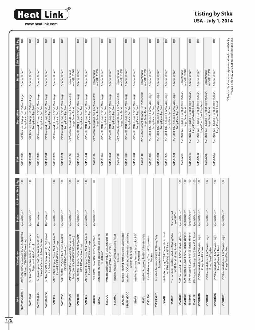
®
LinkHeat
172
www.heatlink.com
Listing by Stk#
* C
he
ck w
ith
yo
ur
loca
l re
pre
sen
tati
ve f
or
ava
ilab
ility
.
** L
ea
d t
ime
may
va
ry. C
all
to c
on
fi rm
tim
e li
ne
.
USA - July 1, 2014S
tk#
De
scri
pti
on
Sta
tus
Lis
t P
rice
/ U
nit
Pg
.
SM
P3
00
SS
-HE
X-H
SM
P 3
65
MB
H S
S S
no
w M
elt
Pa
ne
l 3×
30
HE
X &
HH
Pu
mp
(D
RV
WS
NS
-SS
so
ld s
ep
)
Sp
eci
al O
rde
r*1
10
SM
P3
16
67
Re
pla
ce S
MP
Co
ntr
ol W
ith
#3
16
67
Sn
ow
/Ice
De
tect
or
& M
elt
Co
ntr
ol
Sp
eci
al O
rde
r*1
16
SM
P3
16
67
-Cu
Re
pla
ce C
op
pe
r S
MP
Co
ntr
ol W
ith
#3
16
67
Sn
ow
/Ice
De
tect
or
& M
elt
Co
ntr
ol
Dis
con
tin
ue
d
SM
P3
16
67
-SS
Re
pla
ce S
S S
MP
Co
ntr
ol W
ith
#3
16
67
Sn
ow
/
Ice
De
tect
or
& M
elt
Co
ntr
ol
Dis
con
tin
ue
d
SM
P3
35
SM
P 3
35
MB
H C
op
pe
r S
no
w M
elt
Pa
ne
l 4×
20
Pla
te H
EX
(D
RV
WS
NS
so
ld s
ep
)
Sp
eci
al O
rde
r*1
14
SM
P3
75
SS
SM
P 3
00
MB
H S
S S
no
w M
elt
Pa
ne
l (N
o H
EX
;
DR
VW
SN
S-S
S s
old
se
p)
Sp
eci
al O
rde
r*1
08
SM
P3
75
SS
HS
MP
37
5M
BH
SS
Sn
ow
Me
lt P
an
el w
ith
HH
Pu
mp
(N
o H
EX
; DR
VW
SN
S-S
S s
old
se
p)
Sp
eci
al O
rde
r*1
08
SM
P4
00
DS
MP
40
0M
BH
Co
pp
er
Sn
ow
Me
lt P
an
el (
No
HE
X; D
RV
WS
NS
so
ld s
ep
)
Sp
eci
al O
rde
r*1
12
SM
P4
25
SM
P 4
25
MB
H C
op
pe
r S
no
w M
elt
Pa
ne
l 4×
30
Pla
te H
EX
(D
RV
WS
NS
so
ld s
ep
)
Sp
eci
al O
rde
r*1
14
SO
L0
80
SO
L 8
0M
BH
So
lar
He
at
Exc
ha
ng
er
Pa
ne
lS
pe
cia
l Ord
er*
98
SS
AA
CT
Act
ua
tors
Mo
un
ted
on
Ma
nif
old
an
d W
ire
d
to S
tatL
ink®
SS
AD
DC
Inst
alle
d A
cce
sso
ry 5
61
21
DD
C A
ctu
ato
r o
n
Mix
ing
Va
lve
in S
ST
Pa
ne
l
SS
AM
RC
Inst
alle
d H
ea
tLin
k® C
om
pa
ct M
ixin
g R
ese
t
Co
ntr
ol
SS
AM
XM
Inst
alle
d F
loa
tin
g A
ctio
n M
ixin
g V
alv
e M
oto
r
SS
AM
XM
DD
CIn
sta
lled
DD
C M
ixin
g V
alv
e M
oto
r o
n M
ixin
g
Va
lve
in S
ST
L P
an
el
SS
AP
BIn
sta
lled
Acc
ess
ory
Pre
ssu
re B
ypa
ss f
or
1-1
⁄4"
SS
Ma
nif
old
SS
AS
LIn
sta
lled
Acc
ess
ory
Sta
tLin
k® B
ase
Mo
du
le
SS
AS
LE
MIn
sta
lled
Acc
ess
ory
Sta
tLin
k® E
xpa
nsi
on
Mo
du
le
SS
AS
LE
MH
DIn
sta
lled
Acc
ess
ory
Sta
tLin
k® H
eav
y D
uty
Exp
an
sio
n M
od
ule
SS
AT
HIn
sta
lled
Acc
ess
ory
57
09
4 T
he
rmo
sta
tic
He
ad
on
Mix
ing
Va
lve
in S
ST
Pa
ne
l
SS
AT
H2
Th
erm
ost
ati
c H
ea
d In
sta
lled
on
Mix
ing
Va
lve
in S
ST
Sm
all
Mix
ing
Pa
ne
ls
Dis
con
tin
ue
d;
see
SS
AT
H
SS
M1
04
RS
SM
Re
cess
ed
4 L
oo
p 1
-1⁄4"
SS
Ma
nif
old
Pa
ne
lS
pe
cia
l Ord
er*
10
0
SS
M1
06
RS
SM
Re
cess
ed
6 L
oo
p 1
-1⁄4"
SS
Ma
nif
old
Pa
ne
lS
pe
cia
l Ord
er*
10
0
SS
M1
08
RS
SM
Re
cess
ed
8 L
oo
p 1
-1⁄4"
SS
Ma
nif
old
Pa
ne
lS
pe
cia
l Ord
er*
10
0
SS
M1
10
RS
SM
Re
cess
ed
10
Lo
op
1-1
⁄4" S
S M
an
ifo
ld P
an
el
Sp
eci
al O
rde
r*1
00
SS
PL
R1
04
BS
SP
Re
cess
ed
4 L
oo
p 1
-1⁄4"
SS
Ma
n. L
arg
e
Pu
mp
Pa
ne
l Bo
t. f
ee
d
Sp
eci
al O
rde
r*1
02
SS
PL
R1
04
TS
SP
Re
cess
ed
4 L
oo
p 1
-1⁄4"
SS
Ma
n. L
arg
e
Pu
mp
Pa
ne
l To
p f
ee
d
Sp
eci
al O
rde
r*1
02
SS
PL
R1
06
BS
SP
Re
cess
ed
6 L
oo
p 1
-1⁄4"
SS
Ma
n. L
arg
e
Pu
mp
Pa
ne
l Bo
t. F
ee
d
Sp
eci
al O
rde
r*1
02
SS
PL
R1
06
TS
SP
Re
cess
ed
6 L
oo
p 1
-1⁄4"
SS
Ma
n. L
arg
e
Pu
mp
Pa
ne
l To
p F
ee
d
Sp
eci
al O
rde
r*1
02
Stk
#D
esc
rip
tio
nS
tatu
sL
ist
Pri
ce /
Un
itP
g.
SS
PL
R1
08
BS
SP
Re
cess
ed
8 L
oo
p 1
-1⁄4"
SS
Ma
n. L
arg
e
Pu
mp
Pa
ne
l Bo
t. F
ee
d
Sp
eci
al O
rde
r*1
02
SS
PL
R1
08
TS
SP
Re
cess
ed
8 L
oo
p 1
-1⁄4"
SS
Ma
n. L
arg
e
Pu
mp
Pa
ne
l To
p F
ee
d
Sp
eci
al O
rde
r*1
02
SS
PL
R1
10
BS
SP
Re
cess
ed
10
Lo
op
1-1
⁄4" S
S M
an
. La
rge
Pu
mp
Pa
ne
l Bo
t. F
ee
d
Sp
eci
al O
rde
r*1
02
SS
PL
R1
10
TS
SP
Re
cess
ed
10
Lo
op
1-1
⁄4" S
S M
an
. La
rge
Pu
mp
Pa
ne
l To
p F
ee
d
Sp
eci
al O
rde
r*1
02
SS
PL
R1
12
BS
SP
Re
cess
ed
12
Lo
op
1-1
⁄4" S
S M
an
. La
rge
Pu
mp
Pa
ne
l Bo
t. F
ee
d
Sp
eci
al O
rde
r*1
02
SS
PL
R1
12
TS
SP
Re
cess
ed
12
Lo
op
1-1
⁄4" S
S M
an
. La
rge
Pu
mp
Pa
ne
l To
p F
ee
d
Sp
eci
al O
rde
r*1
02
SS
PL
S1
04
SS
P S
urf
ace
Mo
un
t 4
Lo
op
1-1
⁄4" S
S M
an
ifo
ld
Larg
e P
um
p P
an
el
Dis
con
tin
ue
d;
see
SS
PLS
10
4B
SS
PL
S1
04
BS
SP
SU
RF
MN
T 4
Lo
op
1-1
⁄4" S
S M
an
. La
rge
Pu
mp
Pa
ne
l Bo
t. F
ee
d
Sp
eci
al O
rde
r*1
02
SS
PL
S1
04
TS
SP
SU
RF
MN
T 4
Lo
op
1-1
⁄4" S
S M
an
. La
rge
Pu
mp
Pa
ne
l To
p F
ee
d
Sp
eci
al O
rde
r*1
02
SS
PL
S1
06
SS
P S
urf
ace
Mo
un
t 6
Lo
op
1-1
⁄4" S
S M
an
ifo
ld
Larg
e P
um
p P
an
el
Dis
con
tin
ue
d;
see
SS
PLS
10
6B
SS
PL
S1
06
BS
SP
SU
RF
MN
T 6
Lo
op
1-1
⁄4" S
S M
an
. La
rge
Pu
mp
Pa
ne
l Bo
t. F
ee
d
Sp
eci
al O
rde
r*1
02
SS
PL
S1
06
TS
SP
SU
RF
MN
T 6
Lo
op
1-1
⁄4" S
S M
an
. La
rge
Pu
mp
Pa
ne
l To
p F
ee
d
Sp
eci
al O
rde
r*1
02
SS
PL
S1
08
SS
P S
urf
ace
Mo
un
t 8
Lo
op
1-1
⁄4" S
S M
an
ifo
ld
Larg
e P
um
p P
an
el
Dis
con
tin
ue
d;
see
SS
PLS
10
8B
SS
PL
S1
08
BS
SP
SU
RF
MN
T 8
Lo
op
1-1
⁄4" S
S M
an
. La
rge
Pu
mp
Pa
ne
l Bo
t. F
ee
d
Sp
eci
al O
rde
r*1
02
SS
PL
S1
08
TS
SP
SU
RF
MN
T 8
Lo
op
1-1
⁄4" S
S M
an
. La
rge
Pu
mp
Pa
ne
l To
p F
ee
d
Sp
eci
al O
rde
r*1
02
SS
PL
S1
10
SS
P S
urf
ace
Mo
un
t 1
0 L
oo
p 1
-1⁄4"
SS
Ma
nif
old
Larg
e P
um
p P
an
el
Dis
con
tin
ue
d;
see
SS
PLS
11
0B
SS
PL
S1
10
BS
SP
SU
RF
MN
T 1
0 L
oo
p 1
-1⁄4"
SS
Ma
n. L
arg
e
Pu
mp
Pa
ne
l Bo
t. F
ee
d
Sp
eci
al O
rde
r*1
02
SS
PL
S1
10
TS
SP
SU
RF
MN
T 1
0 L
oo
p 1
-1⁄4"
SS
Ma
n. L
arg
e
Pu
mp
Pa
ne
l To
p F
ee
d
Sp
eci
al O
rde
r*1
02
SS
PL
S1
12
BS
SP
SU
RF
MN
T 1
2 L
oo
p 1
-1⁄4"
SS
Ma
n. L
arg
e
Pu
mp
Pa
ne
l Bo
t. F
ee
d
Sp
eci
al O
rde
r*1
02
SS
PL
S1
12
TS
SP
SU
RF
MN
T 1
2 L
oo
p 1
-1⁄4"
SS
Ma
n. L
arg
e
Pu
mp
Pa
ne
l To
p F
ee
d
Sp
eci
al O
rde
r*1
02
SS
PL
S2
04
SS
P S
UR
F M
NT
4 L
oo
p 1
-1⁄4"
Hig
h F
low
SS
Ma
n.
Larg
e P
um
p P
an
el
Dis
con
tin
ue
d;
see
SS
PLS
20
4B
SS
PL
S2
04
BS
SP
SU
RF
MN
T 4
Lo
op
1-1
⁄4" H
igh
Flo
w S
S M
an
.
Larg
e P
um
p P
an
el B
ot.
Fe
ed
Sp
eci
al O
rde
r*1
02
SS
PL
S2
04
TS
SP
SU
RF
MN
T 4
Lo
op
1-1
⁄4" H
igh
Flo
w S
S M
an
.
Larg
e P
um
p P
an
el T
op
Fe
ed
Sp
eci
al O
rde
r*1
02
SS
PL
S2
06
SS
P S
UR
F M
NT
6 L
oo
p 1
-1⁄4"
Hig
h F
low
SS
Ma
n.
Larg
e P
um
p P
an
el
Dis
con
tin
ue
d;
see
SS
PLS
10
6B
SS
PL
S2
06
BS
SP
SU
RF
MN
T 6
Lo
op
1-1
⁄4" H
igh
Flo
w S
S M
an
.
Larg
e P
um
p P
an
el B
ot.
Fe
ed
Sp
eci
al O
rde
r*1
02
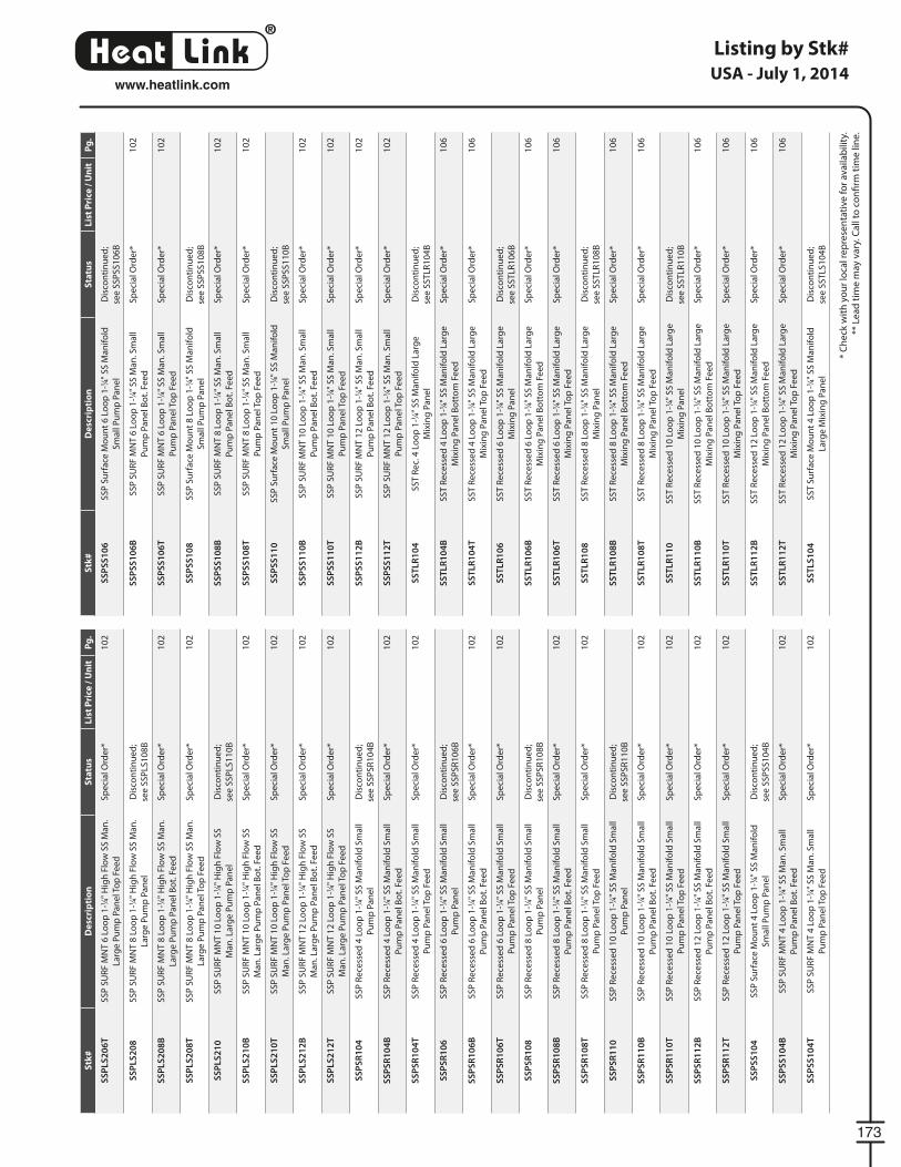
®
LinkHeat
173
www.heatlink.com
Listing by Stk#
* C
he
ck w
ith
yo
ur
loca
l re
pre
sen
tati
ve f
or
ava
ilab
ility
.
** L
ea
d t
ime
may
va
ry. C
all
to c
on
fi rm
tim
e li
ne
.
USA - July 1, 2014S
tk#
De
scri
pti
on
Sta
tus
Lis
t P
rice
/ U
nit
Pg
.
SS
PL
S2
06
TS
SP
SU
RF
MN
T 6
Lo
op
1-1
⁄4" H
igh
Flo
w S
S M
an
.
Larg
e P
um
p P
an
el T
op
Fe
ed
Sp
eci
al O
rde
r*1
02
SS
PL
S2
08
SS
P S
UR
F M
NT
8 L
oo
p 1
-1⁄4"
Hig
h F
low
SS
Ma
n.
Larg
e P
um
p P
an
el
Dis
con
tin
ue
d;
see
SS
PLS
10
8B
SS
PL
S2
08
BS
SP
SU
RF
MN
T 8
Lo
op
1-1
⁄4" H
igh
Flo
w S
S M
an
.
Larg
e P
um
p P
an
el B
ot.
Fe
ed
Sp
eci
al O
rde
r*1
02
SS
PL
S2
08
TS
SP
SU
RF
MN
T 8
Lo
op
1-1
⁄4" H
igh
Flo
w S
S M
an
.
Larg
e P
um
p P
an
el T
op
Fe
ed
Sp
eci
al O
rde
r*1
02
SS
PL
S2
10
SS
P S
UR
F M
NT
10
Lo
op
1-1
⁄4" H
igh
Flo
w S
S
Ma
n. L
arg
e P
um
p P
an
el
Dis
con
tin
ue
d;
see
SS
PLS
11
0B
SS
PL
S2
10
BS
SP
SU
RF
MN
T 1
0 L
oo
p 1
-1⁄4"
Hig
h F
low
SS
Ma
n. L
arg
e P
um
p P
an
el B
ot.
Fe
ed
Sp
eci
al O
rde
r*1
02
SS
PL
S2
10
TS
SP
SU
RF
MN
T 1
0 L
oo
p 1
-1⁄4"
Hig
h F
low
SS
Ma
n. L
arg
e P
um
p P
an
el T
op
Fe
ed
Sp
eci
al O
rde
r*1
02
SS
PL
S2
12
BS
SP
SU
RF
MN
T 1
2 L
oo
p 1
-1⁄4"
Hig
h F
low
SS
Ma
n. L
arg
e P
um
p P
an
el B
ot.
Fe
ed
Sp
eci
al O
rde
r*1
02
SS
PL
S2
12
TS
SP
SU
RF
MN
T 1
2 L
oo
p 1
-1⁄4"
Hig
h F
low
SS
Ma
n. L
arg
e P
um
p P
an
el T
op
Fe
ed
Sp
eci
al O
rde
r*1
02
SS
PS
R1
04
SS
P R
ece
sse
d 4
Lo
op
1-1
⁄4" S
S M
an
ifo
ld S
ma
ll
Pu
mp
Pa
ne
l
Dis
con
tin
ue
d;
see
SS
PS
R1
04
B
SS
PS
R1
04
BS
SP
Re
cess
ed
4 L
oo
p 1
-1⁄4"
SS
Ma
nif
old
Sm
all
Pu
mp
Pa
ne
l Bo
t. F
ee
d
Sp
eci
al O
rde
r*1
02
SS
PS
R1
04
TS
SP
Re
cess
ed
4 L
oo
p 1
-1⁄4"
SS
Ma
nif
old
Sm
all
Pu
mp
Pa
ne
l To
p F
ee
d
Sp
eci
al O
rde
r*1
02
SS
PS
R1
06
SS
P R
ece
sse
d 6
Lo
op
1-1
⁄4" S
S M
an
ifo
ld S
ma
ll
Pu
mp
Pa
ne
l
Dis
con
tin
ue
d;
see
SS
PS
R1
06
B
SS
PS
R1
06
BS
SP
Re
cess
ed
6 L
oo
p 1
-1⁄4"
SS
Ma
nif
old
Sm
all
Pu
mp
Pa
ne
l Bo
t. F
ee
d
Sp
eci
al O
rde
r*1
02
SS
PS
R1
06
TS
SP
Re
cess
ed
6 L
oo
p 1
-1⁄4"
SS
Ma
nif
old
Sm
all
Pu
mp
Pa
ne
l To
p F
ee
d
Sp
eci
al O
rde
r*1
02
SS
PS
R1
08
SS
P R
ece
sse
d 8
Lo
op
1-1
⁄4" S
S M
an
ifo
ld S
ma
ll
Pu
mp
Pa
ne
l
Dis
con
tin
ue
d;
see
SS
PS
R1
08
B
SS
PS
R1
08
BS
SP
Re
cess
ed
8 L
oo
p 1
-1⁄4"
SS
Ma
nif
old
Sm
all
Pu
mp
Pa
ne
l Bo
t. F
ee
d
Sp
eci
al O
rde
r*1
02
SS
PS
R1
08
TS
SP
Re
cess
ed
8 L
oo
p 1
-1⁄4"
SS
Ma
nif
old
Sm
all
Pu
mp
Pa
ne
l To
p F
ee
d
Sp
eci
al O
rde
r*1
02
SS
PS
R1
10
SS
P R
ece
sse
d 1
0 L
oo
p 1
-1⁄4"
SS
Ma
nif
old
Sm
all
Pu
mp
Pa
ne
l
Dis
con
tin
ue
d;
see
SS
PS
R1
10
B
SS
PS
R1
10
BS
SP
Re
cess
ed
10
Lo
op
1-1
⁄4" S
S M
an
ifo
ld S
ma
ll
Pu
mp
Pa
ne
l Bo
t. F
ee
d
Sp
eci
al O
rde
r*1
02
SS
PS
R1
10
TS
SP
Re
cess
ed
10
Lo
op
1-1
⁄4" S
S M
an
ifo
ld S
ma
ll
Pu
mp
Pa
ne
l To
p F
ee
d
Sp
eci
al O
rde
r*1
02
SS
PS
R1
12
BS
SP
Re
cess
ed
12
Lo
op
1-1
⁄4" S
S M
an
ifo
ld S
ma
ll
Pu
mp
Pa
ne
l Bo
t. F
ee
d
Sp
eci
al O
rde
r*1
02
SS
PS
R1
12
TS
SP
Re
cess
ed
12
Lo
op
1-1
⁄4" S
S M
an
ifo
ld S
ma
ll
Pu
mp
Pa
ne
l To
p F
ee
d
Sp
eci
al O
rde
r*1
02
SS
PS
S1
04
SS
P S
urf
ace
Mo
un
t 4
Lo
op
1-1
⁄4" S
S M
an
ifo
ld
Sm
all
Pu
mp
Pa
ne
l
Dis
con
tin
ue
d;
see
SS
PS
S1
04
B
SS
PS
S1
04
BS
SP
SU
RF
MN
T 4
Lo
op
1-1
⁄4" S
S M
an
. Sm
all
Pu
mp
Pa
ne
l Bo
t. F
ee
d
Sp
eci
al O
rde
r*1
02
SS
PS
S1
04
TS
SP
SU
RF
MN
T 4
Lo
op
1-1
⁄4" S
S M
an
. Sm
all
Pu
mp
Pa
ne
l To
p F
ee
d
Sp
eci
al O
rde
r*1
02
Stk
#D
esc
rip
tio
nS
tatu
sL
ist
Pri
ce /
Un
itP
g.
SS
PS
S1
06
SS
P S
urf
ace
Mo
un
t 6
Lo
op
1-1
⁄4" S
S M
an
ifo
ld
Sm
all
Pu
mp
Pa
ne
l
Dis
con
tin
ue
d;
see
SS
PS
S1
06
B
SS
PS
S1
06
BS
SP
SU
RF
MN
T 6
Lo
op
1-1
⁄4" S
S M
an
. Sm
all
Pu
mp
Pa
ne
l Bo
t. F
ee
d
Sp
eci
al O
rde
r*1
02
SS
PS
S1
06
TS
SP
SU
RF
MN
T 6
Lo
op
1-1
⁄4" S
S M
an
. Sm
all
Pu
mp
Pa
ne
l To
p F
ee
d
Sp
eci
al O
rde
r*1
02
SS
PS
S1
08
SS
P S
urf
ace
Mo
un
t 8
Lo
op
1-1
⁄4" S
S M
an
ifo
ld
Sm
all
Pu
mp
Pa
ne
l
Dis
con
tin
ue
d;
see
SS
PS
S1
08
B
SS
PS
S1
08
BS
SP
SU
RF
MN
T 8
Lo
op
1-1
⁄4" S
S M
an
. Sm
all
Pu
mp
Pa
ne
l Bo
t. F
ee
d
Sp
eci
al O
rde
r*1
02
SS
PS
S1
08
TS
SP
SU
RF
MN
T 8
Lo
op
1-1
⁄4" S
S M
an
. Sm
all
Pu
mp
Pa
ne
l To
p F
ee
d
Sp
eci
al O
rde
r*1
02
SS
PS
S1
10
SS
P S
urf
ace
Mo
un
t 1
0 L
oo
p 1
-1⁄4"
SS
Ma
nif
old
Sm
all
Pu
mp
Pa
ne
l
Dis
con
tin
ue
d;
see
SS
PS
S1
10
B
SS
PS
S1
10
BS
SP
SU
RF
MN
T 1
0 L
oo
p 1
-1⁄4"
SS
Ma
n. S
ma
ll
Pu
mp
Pa
ne
l Bo
t. F
ee
d
Sp
eci
al O
rde
r*1
02
SS
PS
S1
10
TS
SP
SU
RF
MN
T 1
0 L
oo
p 1
-1⁄4"
SS
Ma
n. S
ma
ll
Pu
mp
Pa
ne
l To
p F
ee
d
Sp
eci
al O
rde
r*1
02
SS
PS
S1
12
BS
SP
SU
RF
MN
T 1
2 L
oo
p 1
-1⁄4"
SS
Ma
n. S
ma
ll
Pu
mp
Pa
ne
l Bo
t. F
ee
d
Sp
eci
al O
rde
r*1
02
SS
PS
S1
12
TS
SP
SU
RF
MN
T 1
2 L
oo
p 1
-1⁄4"
SS
Ma
n. S
ma
ll
Pu
mp
Pa
ne
l To
p F
ee
d
Sp
eci
al O
rde
r*1
02
SS
TL
R1
04
SS
T R
ec.
4 L
oo
p 1
-1⁄4"
SS
Ma
nif
old
La
rge
Mix
ing
Pa
ne
l
Dis
con
tin
ue
d;
see
SS
TLR
10
4B
SS
TL
R1
04
BS
ST
Re
cess
ed
4 L
oo
p 1
-1⁄4"
SS
Ma
nif
old
La
rge
Mix
ing
Pa
ne
l Bo
tto
m F
ee
d
Sp
eci
al O
rde
r*1
06
SS
TL
R1
04
TS
ST
Re
cess
ed
4 L
oo
p 1
-1⁄4"
SS
Ma
nif
old
La
rge
Mix
ing
Pa
ne
l To
p F
ee
d
Sp
eci
al O
rde
r*1
06
SS
TL
R1
06
SS
T R
ece
sse
d 6
Lo
op
1-1
⁄4" S
S M
an
ifo
ld L
arg
e
Mix
ing
Pa
ne
l
Dis
con
tin
ue
d;
see
SS
TLR
10
6B
SS
TL
R1
06
BS
ST
Re
cess
ed
6 L
oo
p 1
-1⁄4"
SS
Ma
nif
old
La
rge
Mix
ing
Pa
ne
l Bo
tto
m F
ee
d
Sp
eci
al O
rde
r*1
06
SS
TL
R1
06
TS
ST
Re
cess
ed
6 L
oo
p 1
-1⁄4"
SS
Ma
nif
old
La
rge
Mix
ing
Pa
ne
l To
p F
ee
d
Sp
eci
al O
rde
r*1
06
SS
TL
R1
08
SS
T R
ece
sse
d 8
Lo
op
1-1
⁄4" S
S M
an
ifo
ld L
arg
e
Mix
ing
Pa
ne
l
Dis
con
tin
ue
d;
see
SS
TLR
10
8B
SS
TL
R1
08
BS
ST
Re
cess
ed
8 L
oo
p 1
-1⁄4"
SS
Ma
nif
old
La
rge
Mix
ing
Pa
ne
l Bo
tto
m F
ee
d
Sp
eci
al O
rde
r*1
06
SS
TL
R1
08
TS
ST
Re
cess
ed
8 L
oo
p 1
-1⁄4"
SS
Ma
nif
old
La
rge
Mix
ing
Pa
ne
l To
p F
ee
d
Sp
eci
al O
rde
r*1
06
SS
TL
R1
10
SS
T R
ece
sse
d 1
0 L
oo
p 1
-1⁄4"
SS
Ma
nif
old
La
rge
Mix
ing
Pa
ne
l
Dis
con
tin
ue
d;
see
SS
TLR
11
0B
SS
TL
R1
10
BS
ST
Re
cess
ed
10
Lo
op
1-1
⁄4" S
S M
an
ifo
ld L
arg
e
Mix
ing
Pa
ne
l Bo
tto
m F
ee
d
Sp
eci
al O
rde
r*1
06
SS
TL
R1
10
TS
ST
Re
cess
ed
10
Lo
op
1-1
⁄4" S
S M
an
ifo
ld L
arg
e
Mix
ing
Pa
ne
l To
p F
ee
d
Sp
eci
al O
rde
r*1
06
SS
TL
R1
12
BS
ST
Re
cess
ed
12
Lo
op
1-1
⁄4" S
S M
an
ifo
ld L
arg
e
Mix
ing
Pa
ne
l Bo
tto
m F
ee
d
Sp
eci
al O
rde
r*1
06
SS
TL
R1
12
TS
ST
Re
cess
ed
12
Lo
op
1-1
⁄4" S
S M
an
ifo
ld L
arg
e
Mix
ing
Pa
ne
l To
p F
ee
d
Sp
eci
al O
rde
r*1
06
SS
TL
S1
04
SS
T S
urf
ace
Mo
un
t 4
Lo
op
1-1
⁄4" S
S M
an
ifo
ld
Larg
e M
ixin
g P
an
el
Dis
con
tin
ue
d;
see
SS
TLS
10
4B
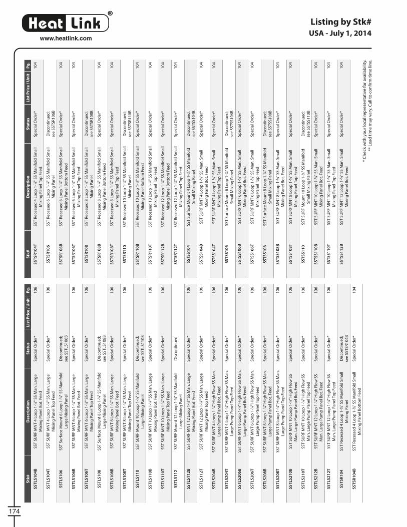
®
LinkHeat
174
www.heatlink.com
Listing by Stk#
* C
he
ck w
ith
yo
ur
loca
l re
pre
sen
tati
ve f
or
ava
ilab
ility
.
** L
ea
d t
ime
may
va
ry. C
all
to c
on
fi rm
tim
e li
ne
.
USA - July 1, 2014S
tk#
De
scri
pti
on
Sta
tus
Lis
t P
rice
/ U
nit
Pg
.
SS
TL
S1
04
BS
ST
SU
RF
MN
T 4
Lo
op
1-1
⁄4" S
S M
an
. La
rge
Mix
ing
Pa
ne
l Bo
t. F
ee
d
Sp
eci
al O
rde
r*1
06
SS
TL
S1
04
TS
ST
SU
RF
MN
T 4
Lo
op
1-1
⁄4" S
S M
an
. La
rge
Mix
ing
Pa
ne
l To
p F
ee
d
Sp
eci
al O
rde
r*1
06
SS
TL
S1
06
SS
T S
urf
ace
Mo
un
t 6
Lo
op
1-1
⁄4" S
S M
an
ifo
ld
Larg
e M
ixin
g P
an
el
Dis
con
tin
ue
d;
see
SS
TLS
10
6B
SS
TL
S1
06
BS
ST
SU
RF
MN
T 6
Lo
op
1-1
⁄4" S
S M
an
. La
rge
Mix
ing
Pa
ne
l Bo
t. F
ee
d
Sp
eci
al O
rde
r*1
06
SS
TL
S1
06
TS
ST
SU
RF
MN
T 6
Lo
op
1-1
⁄4" S
S M
an
. La
rge
Mix
ing
Pa
ne
l To
p F
ee
d
Sp
eci
al O
rde
r*1
06
SS
TL
S1
08
SS
T S
urf
ace
Mo
un
t 8
Lo
op
1-1
⁄4" S
S M
an
ifo
ld
Larg
e M
ixin
g P
an
el
Dis
con
tin
ue
d;
see
SS
TLS
10
8B
SS
TL
S1
08
BS
ST
SU
RF
MN
T 8
Lo
op
1-1
⁄4" S
S M
an
. La
rge
Mix
ing
Pa
ne
l Bo
t. F
ee
d
Sp
eci
al O
rde
r*1
06
SS
TL
S1
08
TS
ST
SU
RF
MN
T 8
Lo
op
1-1
⁄4" S
S M
an
. La
rge
Mix
ing
Pa
ne
l To
p F
ee
d
Sp
eci
al O
rde
r*1
06
SS
TL
S1
10
SS
T S
UR
F M
ou
nt
10
Lo
op
1-1
⁄4" S
S M
an
ifo
ld
Larg
e M
ixin
g P
an
el
Dis
con
tin
ue
d;
see
SS
TLS
11
0B
SS
TL
S1
10
BS
ST
SU
RF
MN
T 1
0 L
oo
p 1
-1⁄4"
SS
Ma
n. L
arg
e
Mix
ing
Pa
ne
l Bo
t. F
ee
d
Sp
eci
al O
rde
r*1
06
SS
TL
S1
10
TS
ST
SU
RF
MN
T 1
0 L
oo
p 1
-1⁄4"
SS
Ma
n. L
arg
e
Mix
ing
Pa
ne
l To
p F
ee
d
Sp
eci
al O
rde
r*1
06
SS
TL
S1
12
SS
T S
UR
F M
ou
nt
12
Lo
op
1-1
⁄4" S
S M
an
ifo
ld
Larg
e M
ixin
g P
an
el
Dis
con
tin
ue
d
SS
TL
S1
12
BS
ST
SU
RF
MN
T 1
2 L
oo
p 1
-1⁄4"
SS
Ma
n. L
arg
e
Mix
ing
Pa
ne
l Bo
t. F
ee
d
Sp
eci
al O
rde
r*1
06
SS
TL
S1
12
TS
ST
SU
RF
MN
T 1
2 L
oo
p 1
-1⁄4"
SS
Ma
n. L
arg
e
Mix
ing
Pa
ne
l To
p F
ee
d
Sp
eci
al O
rde
r*1
06
SS
TL
S2
04
BS
ST
SU
RF
MN
T 4
Lo
op
1-1
⁄4" H
igh
Flo
w S
S M
an
.
Larg
e P
um
p P
an
el B
ot.
Fe
ed
Sp
eci
al O
rde
r*1
06
SS
TL
S2
04
TS
ST
SU
RF
MN
T 4
Lo
op
1-1
⁄4" H
igh
Flo
w S
S M
an
.
Larg
e P
um
p P
an
el T
op
Fe
ed
Sp
eci
al O
rde
r*1
06
SS
TL
S2
06
BS
ST
SU
RF
MN
T 6
Lo
op
1-1
⁄4" H
igh
Flo
w S
S M
an
.
Larg
e P
um
p P
an
el B
ot.
Fe
ed
Sp
eci
al O
rde
r*1
06
SS
TL
S2
06
TS
ST
SU
RF
MN
T 6
Lo
op
1-1
⁄4" H
igh
Flo
w S
S M
an
.
Larg
e P
um
p P
an
el T
op
Fe
ed
Sp
eci
al O
rde
r*1
06
SS
TL
S2
08
BS
ST
SU
RF
MN
T 8
Lo
op
1-1
⁄4" H
igh
Flo
w S
S M
an
.
Larg
e P
um
p P
an
el B
ot.
Fe
ed
Sp
eci
al O
rde
r*1
06
SS
TL
S2
08
TS
ST
SU
RF
MN
T 8
Lo
op
1-1
⁄4" H
igh
Flo
w S
S M
an
.
Larg
e P
um
p P
an
el T
op
Fe
ed
Sp
eci
al O
rde
r*1
06
SS
TL
S2
10
BS
ST
SU
RF
MN
T 1
0 L
oo
p 1
-1⁄4"
Hig
h F
low
SS
Ma
n. L
arg
e P
um
p P
an
el B
ot.
Fe
ed
Sp
eci
al O
rde
r*1
06
SS
TL
S2
10
TS
ST
SU
RF
MN
T 1
0 L
oo
p 1
-1⁄4"
Hig
h F
low
SS
Ma
n. L
arg
e P
um
p P
an
el T
op
Fe
ed
Sp
eci
al O
rde
r*1
06
SS
TL
S2
12
BS
ST
SU
RF
MN
T 1
2 L
oo
p 1
-1⁄4"
Hig
h F
low
SS
Ma
n. L
arg
e P
um
p P
an
el B
ot.
Fe
ed
Sp
eci
al O
rde
r*1
06
SS
TL
S2
12
TS
ST
SU
RF
MN
T 1
2 L
oo
p 1
-1⁄4"
Hig
h F
low
SS
Ma
n. L
arg
e P
um
p P
an
el T
op
Fe
ed
Sp
eci
al O
rde
r*1
06
SS
TS
R1
04
SS
T R
ece
sse
d 4
Lo
op
1-1
⁄4" S
S M
an
ifo
ld S
ma
ll
Mix
ing
Pa
ne
l
Dis
con
tin
ue
d;
see
SS
TS
R1
04
B
SS
TS
R1
04
BS
ST
Re
cess
ed
4 L
oo
p 1
-1⁄4"
SS
Ma
nif
old
Sm
all
Mix
ing
Pa
ne
l Bo
tto
m F
ee
d
Sp
eci
al O
rde
r*1
04
Stk
#D
esc
rip
tio
nS
tatu
sL
ist
Pri
ce /
Un
itP
g.
SS
TS
R1
04
TS
ST
Re
cess
ed
4 L
oo
p 1
-1⁄4"
SS
Ma
nif
old
Sm
all
Mix
ing
Pa
ne
l To
p F
ee
d
Sp
eci
al O
rde
r*1
04
SS
TS
R1
06
SS
T R
ece
sse
d 6
Lo
op
1-1
⁄4" S
S M
an
ifo
ld S
ma
ll
Mix
ing
Pa
ne
l
Dis
con
tin
ue
d;
see
SS
TS
R1
06
B
SS
TS
R1
06
BS
ST
Re
cess
ed
6 L
oo
p 1
-1⁄4"
SS
Ma
nif
old
Sm
all
Mix
ing
Pa
ne
l Bo
tto
m F
ee
d
Sp
eci
al O
rde
r*1
04
SS
TS
R1
06
TS
ST
Re
cess
ed
6 L
oo
p 1
-1⁄4"
SS
Ma
nif
old
Sm
all
Mix
ing
Pa
ne
l To
p F
ee
d
Sp
eci
al O
rde
r*1
04
SS
TS
R1
08
SS
T R
ece
sse
d 8
Lo
op
1-1
⁄4" S
S M
an
ifo
ld S
ma
ll
Mix
ing
Pa
ne
l
Dis
con
tin
ue
d;
see
SS
TS
R1
08
B
SS
TS
R1
08
BS
ST
Re
cess
ed
8 L
oo
p 1
-1⁄4"
SS
Ma
nif
old
Sm
all
Mix
ing
Pa
ne
l Bo
tto
m F
ee
d
Sp
eci
al O
rde
r*1
04
SS
TS
R1
08
TS
ST
Re
cess
ed
8 L
oo
p 1
-1⁄4"
SS
Ma
nif
old
Sm
all
Mix
ing
Pa
ne
l To
p F
ee
d
Sp
eci
al O
rde
r*1
04
SS
TS
R1
10
SS
T R
ece
sse
d 1
0 L
oo
p 1
-1⁄4"
SS
Ma
nif
old
Sm
all
Mix
ing
Pa
ne
l
Dis
con
tin
ue
d;
see
SS
TS
R1
10
B
SS
TS
R1
10
BS
ST
Re
cess
ed
10
Lo
op
1-1
⁄4" S
S M
an
ifo
ld S
ma
ll
Mix
ing
Pa
ne
l Bo
tto
m F
ee
d
Sp
eci
al O
rde
r*1
04
SS
TS
R1
10
TS
ST
Re
cess
ed
10
Lo
op
1-1
⁄4" S
S M
an
ifo
ld S
ma
ll
Mix
ing
Pa
ne
l To
p F
ee
d
Sp
eci
al O
rde
r*1
04
SS
TS
R1
12
BS
ST
Re
cess
ed
12
Lo
op
1-1
⁄4" S
S M
an
ifo
ld S
ma
ll
Mix
ing
Pa
ne
l Bo
tto
m F
ee
d
Sp
eci
al O
rde
r*1
04
SS
TS
R1
12
TS
ST
Re
cess
ed
12
Lo
op
1-1
⁄4" S
S M
an
ifo
ld S
ma
ll
Mix
ing
Pa
ne
l To
p F
ee
d
Sp
eci
al O
rde
r*1
04
SS
TS
S1
04
SS
T S
urf
ace
Mo
un
t 4
Lo
op
1-1
⁄4" S
S M
an
ifo
ld
Sm
all
Mix
ing
Pa
ne
l
Dis
con
tin
ue
d;
see
SS
TS
S1
04
B
SS
TS
S1
04
BS
ST
SU
RF
MN
T 4
Lo
op
1-1
⁄4" S
S M
an
. Sm
all
Mix
ing
Pa
ne
l Bo
t. F
ee
d
Sp
eci
al O
rde
r*1
04
SS
TS
S1
04
TS
ST
SU
RF
MN
T 4
Lo
op
1-1
⁄4" S
S M
an
. Sm
all
Mix
ing
Pa
ne
l To
p F
ee
d
Sp
eci
al O
rde
r*1
04
SS
TS
S1
06
SS
T S
urf
ace
Mo
un
t 6
Lo
op
1-1
⁄4" S
S M
an
ifo
ld
Sm
all
Mix
ing
Pa
ne
l
Dis
con
tin
ue
d;
see
SS
TS
S1
06
B
SS
TS
S1
06
BS
ST
SU
RF
MN
T 6
Lo
op
1-1
⁄4" S
S M
an
. Sm
all
Mix
ing
Pa
ne
l Bo
t. F
ee
d
Sp
eci
al O
rde
r*1
04
SS
TS
S1
06
TS
ST
SU
RF
MN
T 6
Lo
op
1-1
⁄4" S
S M
an
. Sm
all
Mix
ing
Pa
ne
l To
p F
ee
d
Sp
eci
al O
rde
r*1
04
SS
TS
S1
08
SS
T S
urf
ace
Mo
un
t 8
Lo
op
1-1
⁄4" S
S M
an
ifo
ld
Sm
all
Mix
ing
Pa
ne
l
Dis
con
tin
ue
d;
see
SS
TS
S1
08
B
SS
TS
S1
08
BS
ST
SU
RF
MN
T 8
Lo
op
1-1
⁄4" S
S M
an
. Sm
all
Mix
ing
Pa
ne
l Bo
t. F
ee
d
Sp
eci
al O
rde
r*1
04
SS
TS
S1
08
TS
ST
SU
RF
MN
T 8
Lo
op
1-1
⁄4" S
S M
an
. Sm
all
Mix
ing
Pa
ne
l To
p F
ee
d
Sp
eci
al O
rde
r*1
04
SS
TS
S1
10
SS
T S
UR
F M
ou
nt
10
Lo
op
1-1
⁄4" S
S M
an
ifo
ld
Sm
all
Mix
ing
Pa
ne
l
Dis
con
tin
ue
d;
see
SS
TS
S1
10
B
SS
TS
S1
10
BS
ST
SU
RF
MN
T 1
0 L
oo
p 1
-1⁄4"
SS
Ma
n. S
ma
ll
Mix
ing
Pa
ne
l Bo
t. F
ee
d
Sp
eci
al O
rde
r*1
04
SS
TS
S1
10
TS
ST
SU
RF
MN
T 1
0 L
oo
p 1
-1⁄4"
SS
Ma
n. S
ma
ll
Mix
ing
Pa
ne
l To
p F
ee
d
Sp
eci
al O
rde
r*1
04
SS
TS
S1
12
BS
ST
SU
RF
MN
T 1
2 L
oo
p 1
-1⁄4"
SS
Ma
n. S
ma
ll
Mix
ing
Pa
ne
l Bo
t. F
ee
d
Sp
eci
al O
rde
r*1
04

®
LinkHeat
175
www.heatlink.com
Listing by Stk#
* C
he
ck w
ith
yo
ur
loca
l re
pre
sen
tati
ve f
or
ava
ilab
ility
.
** L
ea
d t
ime
may
va
ry. C
all
to c
on
fi rm
tim
e li
ne
.
USA - July 1, 2014S
tk#
De
scri
pti
on
Sta
tus
Lis
t P
rice
/ U
nit
Pg
.
SS
TS
S1
12
TS
ST
SU
RF
MN
T 1
2 L
oo
p 1
-1⁄4"
SS
Ma
n. S
ma
ll
Mix
ing
Pa
ne
l To
p F
ee
d
Sp
eci
al O
rde
r*1
04
TM
P0
40
TM
P 4
0M
BH
3-w
ay M
ixin
g P
an
el
72
TM
P0
70
TM
P 7
0M
BH
3-w
ay M
ixin
g P
an
el
72
TM
P0
70
ZT
MP
70
MB
H 3
-way
Mix
ing
Pa
ne
l wit
h Z
on
ing
Sp
eci
al O
rde
r*7
4
TM
P0
85
DP
TM
P 8
5M
BH
Du
al P
um
p 3
-way
Mix
ing
pa
ne
l7
6
TM
P2
00
DT
TM
P 2
00
MB
H 2
-Te
mp
era
ture
3-w
ay M
ixin
g
Pa
ne
l
78
TS
M3
04
RT
SM
Re
cess
ed
4 L
oo
p T
wis
tSe
al®
Min
i
Mu
ltip
ort
Ma
nif
old
Pa
ne
l
Dis
con
tin
ue
d
TS
M3
06
RT
SM
Re
cess
ed
6 L
oo
p T
wis
tSe
al®
Min
i
Mu
ltip
ort
Ma
nif
old
Pa
ne
l
Dis
con
tin
ue
d
TS
M3
08
RT
SM
Re
cess
ed
8 L
oo
p T
wis
tSe
al®
Min
i
Mu
ltip
ort
Ma
nif
old
Pa
ne
l
Dis
con
tin
ue
d
TS
M3
10
RT
SM
Re
cess
ed
10
Lo
op
Tw
istS
ea
l® M
ini
Mu
ltip
ort
Ma
nif
old
Pa
ne
l
Dis
con
tin
ue
d
TW
H0
70
TW
H 7
0M
BH
Ta
nk
less
Wat
er
He
ate
r M
ixin
g
Pa
ne
l
80
TW
H0
70
PT
WH
70
MB
H T
an
kle
ss W
ate
r H
ea
ter
Mix
ing
Pa
ne
l (D
HW
Pri
ori
ty O
pt)
Sp
eci
al O
rde
r*8
2
TW
H0
70
PS
TW
H 7
0M
BH
Ta
nk
less
Wat
er
He
ate
r M
ixin
g
Pa
ne
l wit
h D
HW
Pri
ori
ty
Dis
con
tin
ue
d;
see
TW
H0
70
P
TW
H0
70
XP
TW
H 7
0M
BH
HH
Ta
nk
less
Wat
er
He
ate
r
Mix
ing
Pa
ne
l (D
HW
Pri
ori
ty O
pt)
82
TW
H0
70
XP
ST
WH
70
MB
H H
H T
an
kle
ss W
ate
r H
ea
ter
Mix
ing
Pa
ne
l wit
h D
HW
Pri
ori
ty
Dis
con
tin
ue
d;
see
TW
H0
70
XP
TW
H0
70
XP
ZT
WH
70
MB
H H
igh
He
ad
Ta
nk
less
Wat
er
He
ate
r M
ixin
g P
an
el w
ith
Zo
nin
g
Sp
eci
al O
rde
r*8
4
TW
H0
70
ZT
WH
70
MB
H T
an
kle
ss W
ate
r H
ea
ter
Mix
ing
Pa
ne
l wit
h Z
on
ing
Sp
eci
al O
rde
r*8
4
V1
01
V1
00
Bo
iler
Pa
ne
lN
ew
!6
4
V1
02
V1
00
Bo
iler
Pa
ne
l Hig
h C
ap
aci
tyN
ew
!6
4
WH
P1
30
WH
P 1
30
MB
H W
ate
r H
ea
ter
Pu
mp
Pa
ne
l wit
h
DH
W P
rio
rity
Dis
con
tin
ue
d;
see
WH
P1
30
P
WH
P1
30
PW
HP
13
0M
BH
Wat
er
He
ate
r P
um
p P
an
el
(DH
W P
rio
rity
Op
tio
na
l)
Sp
eci
al O
rde
r*9
0
WH
TW
SH
34
3⁄4"
Nit
rile
Wa
she
r fo
r P
an
els
15
6
wsb
2#
2 W
ate
r S
am
ple
Bo
ttle
w/C
ap
- G
en
era
l5
7
ZM
P0
06
ZM
P 6
Bra
nch
Zo
ne
Mix
ing
Pa
ne
lD
isco
nti
nu
ed
ZM
P0
08
ZM
P 8
Bra
nch
Zo
ne
Mix
ing
Pa
ne
lD
isco
nti
nu
ed
ZM
P0
10
ZM
P 1
0 B
ran
ch Z
on
e M
ixin
g P
an
el
Dis
con
tin
ue
d
ZM
P0
12
ZM
P 1
2 B
ran
ch Z
on
e M
ixin
g P
an
el
Dis
con
tin
ue
d
ZM
P0
14
ZM
P 1
4 B
ran
ch Z
on
e M
ixin
g P
an
el
Dis
con
tin
ue
d

®
LinkHeat
176
www.heatlink.com
NotesUSA - July 1, 2014

© HeatLink Group Inc.Printed in USA
HeatLink, DryAbove, DryBelow, EasyFit, EndBend, HeatSeal, PexCube, PureLink, and SpacerClip are either registered trademarks or trademarks of HeatLink Group Inc.
®
Heat Link
L3820us
Toll Free: 1-800-661-5332Fax: 1-800-869-6098
[email protected]@heatlink.comwww.heatlink.com