heat transfer lab manual - · pdf filechemical engineering department institute of...
TRANSCRIPT
HEAT TRANSFER
LAB MANUAL
NIRMA UNIVERSITY
INSTITUTE OF TECHNOLOGY
CHEMICAL ENGINEERING DEPARTMENT
Chemical Engineering Department
Institute of Technology, Nirma University
Heat Transfer Operation- Lab Manual
List of Experiments:
1. Thermal conductivity apparatus
2. Thermal conductivity of metal rod
3. Thermal conductivity of insulating powder
4. Heat Transfer in natural convection
5. Heat Transfer in forced convection
6. Extended surface equipment
7. Parallel flow heat exchanger
8. Counter flow heat exchanger
9. Shell and Tube heat exchanger
10. Finned tube heat exchanger
11. Emissivity measurement apparatus
12. Drop wise and film wise condensation apparatus
Chemical Engineering Department
Institute of Technology, Nirma University
Heat Transfer Operation- Lab Manual
Date: Roll No:
Practical No:
THERMAL CONDUCTIVITY APPARATUS
Objective: After this experiment student will able to understand how to determine the Thermal
Conductivity of given specimen.
Apparatus: Two slab guarded hot plate thermal conductivity apparatus, Specimen, Insulation
(Glass wool) Packets.
Utility: Water, Electric Supply.
Theory:
Principle of the guarded hot plate method:
A sketch of the apparatus is shown in Fig. (1). The essential parts the Hot plate, the cold plate,
the heater assembly, thermocouples and the specimen, in position, are shown in the same figure.
For measurement of the thermal conductivity K what is required is to have one dimensional heat
flow through the flat specimen, an arrangement for maintaining its faces at the constant
temperature and metering method to measure the heat flow through a known area.
To eliminate the distortion caused by the edge losses in unidirectional heat flow from the central
plate, it is surrounded by a guard ring heater separately. Temperatures are measured by calibrated
thermocouples, attached to the plates or to the specimen at the hot and the cold faces. Two
specimens are used to ensure that all the heat comes out to the specimen only.
Knowing the heat input to the central plate heater, the temperature difference across the
specimen, its thickness and the area, one can calculate the K by the following formula.
Where,
K Thermal Conductivity of the sample, W /m C
q Heat flow rate in the specimen, W
A Area of the specimen, m2
Th Hot plate temperature, C
Tc Cold plate temperature, C
L Thickness of the specimen, m
If the specimen thickness are different and the respective hot and cold temperatures are
different than,
Where suffix 1 stands for upper specimen and 2 stands for lower specimen.
)(*2
*
ch TTA
LqK
c2h2
2
c1h1
1
T - TT - T2
LL
A
qK
Chemical Engineering Department
Institute of Technology, Nirma University
Heat Transfer Operation- Lab Manual
Apparatus description:
The heater plate is surrounded by a guard heater for stabilising the temperature of the primary
heater and to prevent heat loss radially around the edges. The primary and guard heaters are made
of Nichrome wire packed between upper and lower mica sheets. These heaters together with
upper and lower copper plates and rings from the heater plate assembly.
Two thermocouples (1 & 2) are used to measure the hot face temperature at the upper and lower
central plate assembly copper plates. Two more thermocouples (3 & 4) are used to check balance
in both the heater inputs (see figure 1).
Specimens are held between the heater and cooling unit on each side of the apparatus.
Thermocouples (5 & 6) measure the temperature of the upper cooling plate and lower cooling
plate respectively.
The cooling chamber is a composite assembly of spiral grooved Aluminium casting and
aluminium cover with entry and exit adopters for water inlet and outlet.
Procedure:
The specimens are placed on either side of the heating plate assembly uniformly touching the
cooling plates. The outer container is filled with loosely filled insulation such as glass wool
supplied in small packets. The cooling circuit is started. Then calculated heat input is given to the
central and guard heaters through separate single phase power supply lines with dimmerstat in
each line and it is adjusted to maintain the desired temperature (For ensuring no radial heat
transfer, generally outer heater input is 2.5 to 3.0 times more than the central heating input). The
guard heater input is adjusted in such a way that there is no radial heat flow, which is checked
from thermocouples readings are recorded accordingly. The input of the central heater (current &
voltage, watts) and the thermocouple readings are recorded every 10 minutes till a reasonably
steady state condition is reached. The readings are recorded in the observation table. The final
steady state values are taken for calculations.
Precautions:
Keep the dimmerstat to 0 voltage position at start.
Increase the voltage gradually of the two heaters during initial set-up experimentation.
Start the cooling circuit before switching on the heaters and adjust the flow rates so that
practically there is no temperature rise in the circulation fluid.
Keep the heater plate undisturbed and adjust the cooling plates after keeping the samples with
the help of nuts gently.
Keep the loose filled in insulation (glass wool) packets gently and remove them slowly so that
they do not disturb the thermocouples’ terminals and heater wires.
Chemical Engineering Department
Institute of Technology, Nirma University
Heat Transfer Operation- Lab Manual
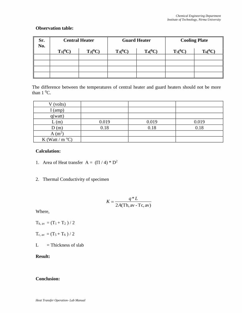
Observation table:
Sr.
No.
Central Heater Guard Heater Cooling Plate
T1(0C) T2(0C) T3(0C) T4(0C) T5(0C) T6(0C)
The difference between the temperatures of central heater and guard heaters should not be more
than 1 0C.
V (volts)
I (amp)
q(watt)
L (m) 0.019 0.019 0.019
D (m) 0.18 0.18 0.18
A (m2)
K (Watt / m oC)
Calculation:
1. Area of Heat transfer A = ( / 4) * D2
2. Thermal Conductivity of specimen
Where,
Th, av = (T1 + T2 ) / 2
Tc, av = (T5 + T6 ) / 2
L = Thickness of slab
Result:
Conclusion:
)av Tc, - av Th,(2
*
A
LqK
Chemical Engineering Department
Institute of Technology, Nirma University
Heat Transfer Operation- Lab Manual
Quiz:
1. Write the Fourier rate equation for heat transfer by conduction. Give physical significance of
each term.
2. Why there is a negative sign in the Fourier’s law of heat conduction?
3. What is meant by one-dimensional steady state heat conduction?
4. List some good conductors of heat; some poor conductors.
5. What is the function of guard heater in Two Slab Guarded Hot Plate Method?
Chemical Engineering Department
Institute of Technology, Nirma University
Heat Transfer Operation- Lab Manual
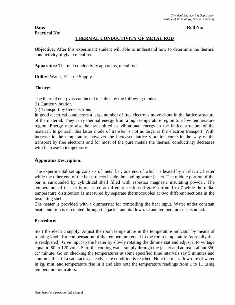
Date: Roll No:
Practical No: THERMAL CONDUCTIVITY OF METAL ROD
Objective: After this experiment student will able to understand how to determine the thermal
conductivity of given metal rod.
Apparatus: Thermal conductivity apparatus, metal rod.
Utility: Water, Electric Supply.
Theory:
The thermal energy is conducted in solids by the following modes:
(i) Lattice vibration
(ii) Transport by free electrons
In good electrical conductors a large number of free electrons move about in the lattice structure
of the material. They carry thermal energy from a high temperature region to a low temperature
region. Energy may also be transmitted as vibrational energy in the lattice structure of the
material. In general, this latter mode of transfer is not as large as the electron transport. With
increase in the temperature, however the increased lattice vibration come in the way of the
transport by free electrons and for most of the pure metals the thermal conductivity decreases
with increase in temperature.
Apparatus Description:
The experimental set up consists of metal bar, one end of which is heated by an electric heater
while the other end of the bar projects inside the cooling water jacket. The middle portion of the
bar is surrounded by cylindrical shell filled with asbestos magnesia insulating powder. The
temperature of the bar is measured at different sections (figure1) from 1 to 7 while the radial
temperature distribution is measured by separate thermocouples at two different sections in the
insulating shell.
The heater is provided with a dimmerstat for controlling the heat input. Water under constant
heat condition is circulated through the jacket and its flow rate and temperature rise is noted.
Procedure:
Start the electric supply. Adjust the room temperature in the temperature indicator by means of
rotating knob, for compensation of the temperature equal to the room temperature (normally this
is readjusted). Give input to the heater by slowly rotating the dimmerstat and adjust it to voltage
equal to 80 to 120 volts. Start the cooling water supply through the jacket and adjust it about 350
cc/ minute. Go on checking the temperatures at some specified time intervals say 5 minutes and
continue this till a satisfactory steady state condition is reached. Note the mass flow rate of water
in kg/ min. and temperature rise in it and also note the temperature readings from 1 to 11 using
temperature indicators.
Chemical Engineering Department
Institute of Technology, Nirma University
Heat Transfer Operation- Lab Manual
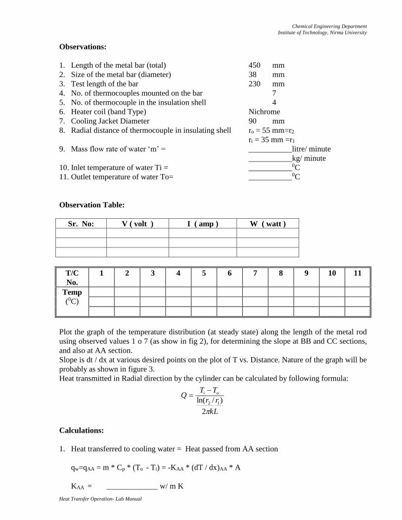
Observations:
1. Length of the metal bar (total) 450 mm
2. Size of the metal bar (diameter) 38 mm
3. Test length of the bar 230 mm
4. No. of thermocouples mounted on the bar 7
5. No. of thermocouple in the insulation shell 4
6. Heater coil (band Type) Nichrome
7. Cooling Jacket Diameter 90 mm
8. Radial distance of thermocouple in insulating shell ro = 55 mm=r2
ri = 35 mm =r1
9. Mass flow rate of water ‘m’ = ___________litre/ minute
___________kg/ minute
10. Inlet temperature of water Ti = ___________0C
11. Outlet temperature of water To= ___________0C
Observation Table:
Sr. No: V ( volt ) I ( amp ) W ( watt )
T/C
No.
1 2 3 4 5 6 7 8 9 10 11
Temp
(0C)
Plot the graph of the temperature distribution (at steady state) along the length of the metal rod
using observed values 1 o 7 (as show in fig 2), for determining the slope at BB and CC sections,
and also at AA section.
Slope is dt / dx at various desired points on the plot of T vs. Distance. Nature of the graph will be
probably as shown in figure 3.
Heat transmitted in Radial direction by the cylinder can be calculated by following formula:
Calculations:
1. Heat transferred to cooling water = Heat passed from AA section
qw=qAA = m * Cp * (To - Ti) = -KAA * (dT / dx)AA * A
KAA = _____________ w/ m K
kL
rr
TTQ oi
2
)/ln( 12
Chemical Engineering Department
Institute of Technology, Nirma University
Heat Transfer Operation- Lab Manual
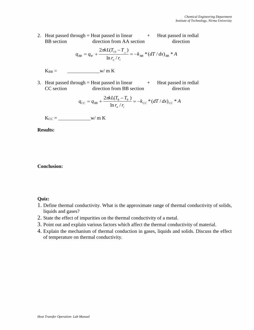
2. Heat passed through = Heat passed in linear + Heat passed in redial
BB section direction from AA section direction
KBB = _____________w/ m K
3. Heat passed through = Heat passed in linear + Heat passed in redial
CC section direction from BB section direction
KCC = _____________w/ m K
Results:
Conclusion:
Quiz:
1. Define thermal conductivity. What is the approximate range of thermal conductivity of solids,
liquids and gases?
2. State the effect of impurities on the thermal conductivity of a metal.
3. Point out and explain various factors which affect the thermal conductivity of material.
4. Explain the mechanism of thermal conduction in gases, liquids and solids. Discuss the effect
of temperature on thermal conductivity.
AdxdTkrr
TTkLqq BBBB
io
WBB *)/(*/ln
)(21110
AdxdTkrr
TTkLqq CCCC
io
BBCC *)/(*/ln
)(2 98
Chemical Engineering Department
Institute of Technology, Nirma University
Heat Transfer Operation- Lab Manual
Date: Roll No:
Practical No:
THERMAL CONDUCTIVITY OF INSULATING POWDER
Objective: After this experiment student will able to understand how to determine the thermal
conductivity of given insulating powder.
Apparatus: Conductivity Instrument, Insulating Powder
Utility: Electric Supply
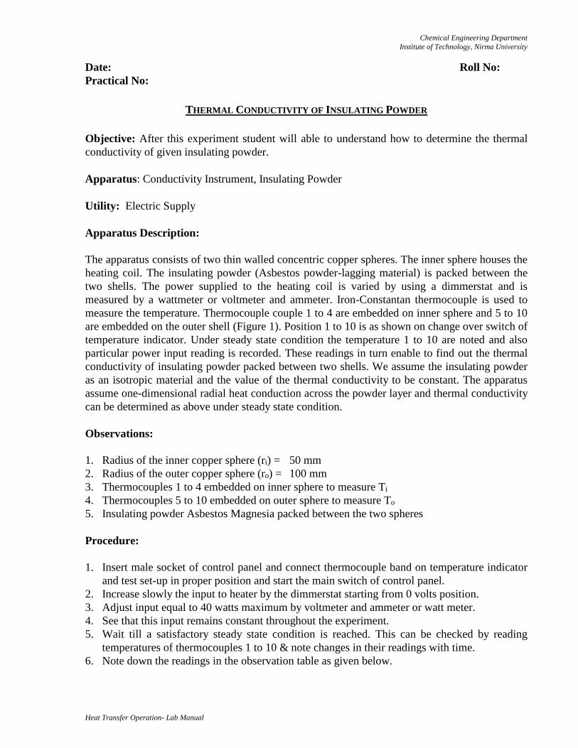
Apparatus Description:
The apparatus consists of two thin walled concentric copper spheres. The inner sphere houses the
heating coil. The insulating powder (Asbestos powder-lagging material) is packed between the
two shells. The power supplied to the heating coil is varied by using a dimmerstat and is
measured by a wattmeter or voltmeter and ammeter. Iron-Constantan thermocouple is used to
measure the temperature. Thermocouple couple 1 to 4 are embedded on inner sphere and 5 to 10
are embedded on the outer shell (Figure 1). Position 1 to 10 is as shown on change over switch of
temperature indicator. Under steady state condition the temperature 1 to 10 are noted and also
particular power input reading is recorded. These readings in turn enable to find out the thermal
conductivity of insulating powder packed between two shells. We assume the insulating powder
as an isotropic material and the value of the thermal conductivity to be constant. The apparatus
assume one-dimensional radial heat conduction across the powder layer and thermal conductivity
can be determined as above under steady state condition.
Observations:
1. Radius of the inner copper sphere (ri) = 50 mm
2. Radius of the outer copper sphere (ro) = 100 mm
3. Thermocouples 1 to 4 embedded on inner sphere to measure Ti
4. Thermocouples 5 to 10 embedded on outer sphere to measure To
5. Insulating powder Asbestos Magnesia packed between the two spheres
Procedure:
1. Insert male socket of control panel and connect thermocouple band on temperature indicator
and test set-up in proper position and start the main switch of control panel.
2. Increase slowly the input to heater by the dimmerstat starting from 0 volts position.
3. Adjust input equal to 40 watts maximum by voltmeter and ammeter or watt meter.
4. See that this input remains constant throughout the experiment.
5. Wait till a satisfactory steady state condition is reached. This can be checked by reading
temperatures of thermocouples 1 to 10 & note changes in their readings with time.
6. Note down the readings in the observation table as given below.
Chemical Engineering Department
Institute of Technology, Nirma University
Heat Transfer Operation- Lab Manual
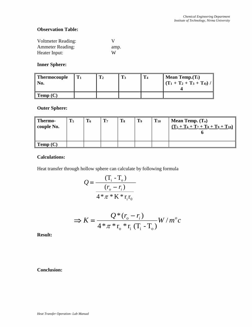
Observation Table:
Voltmeter Reading: V
Ammeter Reading: amp.
Heater Input: W
Inner Sphere:
Thermocouple
No.
T1 T2 T3 T4 Mean Temp.(Ti)
(T1 + T2 + T3 + T4)) /
4
Temp (C)
Outer Sphere:
Thermo-
couple No.
T5 T6 T7 T8 T9 T10 Mean Temp. (To)
(T5 + T6 + T7 + T8 + T9 + T10)
6
Temp (C)
Calculations:
Heat transfer through hollow sphere can calculate by following formula
Result:
Conclusion:
rr*K* * 4
)(
)T - (T
0i
oi
io rrQ
cmWrrQ
K oio /)T - (T r*r* * 4
)(*
oiio
Chemical Engineering Department
Institute of Technology, Nirma University
Heat Transfer Operation- Lab Manual
Quiz:
1. Which aspect makes the thermal conductivity of insulating materials lower than that of
metals?
2. State the assumptions made with reference to insulating material.
3. Write commonly used insulations for heating and cooling applications.
4. Explain why quilt is better insulator than a woollen blanket of the same thickness.
Chemical Engineering Department
Institute of Technology, Nirma University
Heat Transfer Operation- Lab Manual
Date: Roll No:
Practical No:
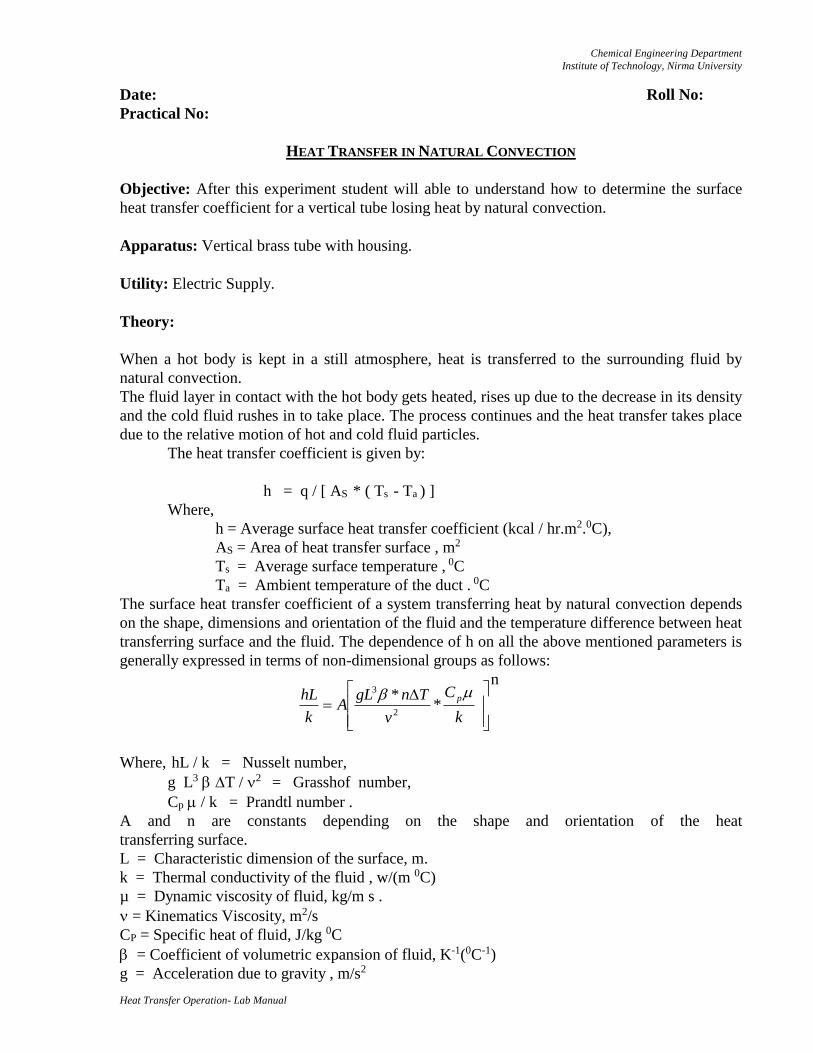
HEAT TRANSFER IN NATURAL CONVECTION
Objective: After this experiment student will able to understand how to determine the surface
heat transfer coefficient for a vertical tube losing heat by natural convection.
Apparatus: Vertical brass tube with housing.
Utility: Electric Supply.
Theory:
When a hot body is kept in a still atmosphere, heat is transferred to the surrounding fluid by
natural convection.
The fluid layer in contact with the hot body gets heated, rises up due to the decrease in its density
and the cold fluid rushes in to take place. The process continues and the heat transfer takes place
due to the relative motion of hot and cold fluid particles.
The heat transfer coefficient is given by:
h = q / [ AS * ( Ts - Ta ) ]
Where,
h = Average surface heat transfer coefficient (kcal / hr.m2.0C),
AS = Area of heat transfer surface , m2
Ts = Average surface temperature , 0C
Ta = Ambient temperature of the duct . 0C
The surface heat transfer coefficient of a system transferring heat by natural convection depends
on the shape, dimensions and orientation of the fluid and the temperature difference between heat
transferring surface and the fluid. The dependence of h on all the above mentioned parameters is
generally expressed in terms of non-dimensional groups as follows:
Where, hL / k = Nusselt number,
g L3 T / 2 = Grasshof number,
Cp / k = Prandtl number .
A and n are constants depending on the shape and orientation of the heat
transferring surface.
L = Characteristic dimension of the surface, m.
k = Thermal conductivity of the fluid , w/(m 0C)
µ = Dynamic viscosity of fluid, kg/m s .
= Kinematics Viscosity, m2/s
CP = Specific heat of fluid, J/kg 0C
= Coefficient of volumetric expansion of fluid, K-1(0C-1)
g = Acceleration due to gravity , m/s2
n
**2
3
k
C
v
TngLA
k
hL p
Chemical Engineering Department
Institute of Technology, Nirma University
Heat Transfer Operation- Lab Manual
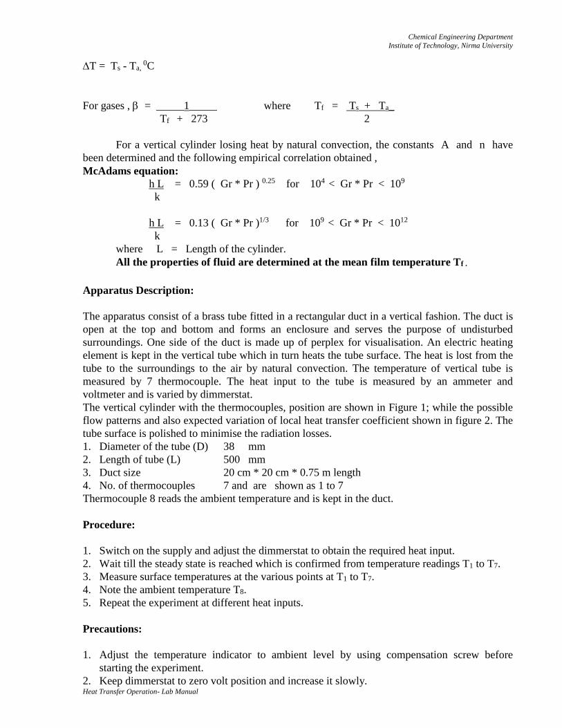
T = Ts - Ta, 0C
For gases , = _____1_____ where Tf = Ts + Ta_
Tf + 273 2
For a vertical cylinder losing heat by natural convection, the constants A and n have
been determined and the following empirical correlation obtained ,
McAdams equation:
h L = 0.59 ( Gr * Pr ) 0.25 for 104 < Gr * Pr < 109
k
h L = 0.13 ( Gr * Pr )1/3 for 109 < Gr * Pr < 1012
k
where L = Length of the cylinder.
All the properties of fluid are determined at the mean film temperature Tf .
Apparatus Description:
The apparatus consist of a brass tube fitted in a rectangular duct in a vertical fashion. The duct is
open at the top and bottom and forms an enclosure and serves the purpose of undisturbed
surroundings. One side of the duct is made up of perplex for visualisation. An electric heating
element is kept in the vertical tube which in turn heats the tube surface. The heat is lost from the
tube to the surroundings to the air by natural convection. The temperature of vertical tube is
measured by 7 thermocouple. The heat input to the tube is measured by an ammeter and
voltmeter and is varied by dimmerstat.
The vertical cylinder with the thermocouples, position are shown in Figure 1; while the possible
flow patterns and also expected variation of local heat transfer coefficient shown in figure 2. The
tube surface is polished to minimise the radiation losses.
1. Diameter of the tube (D) 38 mm
2. Length of tube (L) 500 mm
3. Duct size 20 cm * 20 cm * 0.75 m length
4. No. of thermocouples 7 and are shown as 1 to 7
Thermocouple 8 reads the ambient temperature and is kept in the duct.
Procedure:
1. Switch on the supply and adjust the dimmerstat to obtain the required heat input.
2. Wait till the steady state is reached which is confirmed from temperature readings T1 to T7.
3. Measure surface temperatures at the various points at T1 to T7.
4. Note the ambient temperature T8.
5. Repeat the experiment at different heat inputs.
Precautions:
1. Adjust the temperature indicator to ambient level by using compensation screw before
starting the experiment.
2. Keep dimmerstat to zero volt position and increase it slowly.
Chemical Engineering Department
Institute of Technology, Nirma University
Heat Transfer Operation- Lab Manual
3. Use the proper range of ammeter and voltmeter.
4. Operate the change over switch of temperature indicator gently from one position to other,
i.e. from 1 to 8 positions.
5. Never exceed 80 watts.
Observation Table: Input to heater
Sr. No: V ( volt ) I ( amp ) W ( watt )
Sr.
No.
T1
( 0C )
T2
( 0C )
T3
( 0C )
T4
( 0C )
T5
( 0C )
T6
( 0C )
T7
( 0C )
T8 = Ta
( 0C )
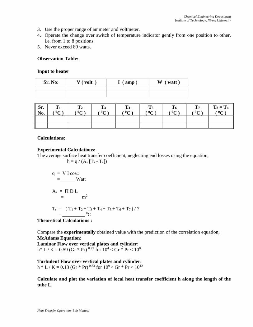
Calculations:
Experimental Calculations:
The average surface heat transfer coefficient, neglecting end losses using the equation,
h = q / (As [Ts - Ta])
q = V I cos
=______ Watt
As = D L
= m2
Ts = ( T1 + T2 + T3 + T4 + T5 + T6 + T7 ) / 7
= _________ 0C
Theoretical Calculations :
Compare the experimentally obtained value with the prediction of the correlation equation,
McAdams Equation:
Laminar Flow over vertical plates and cylinder:
h* L / K = 0.59 (Gr * Pr) 0.25 for 104 < Gr * Pr < 108
Turbulent Flow over vertical plates and cylinder:
h * L / K = 0.13 (Gr * Pr) 0.33 for 109 < Gr * Pr < 1012
Calculate and plot the variation of local heat transfer coefficient h along the length of the
tube L.
Chemical Engineering Department
Institute of Technology, Nirma University
Heat Transfer Operation- Lab Manual
Result:
Sr. No h ( Experimental )
( W/m2.0C )
h ( Theoretical )
( W/m2.0C )
1
2
3
Conclusion:
Quiz:
1. Differentiate between mechanisms of heat transfer by free and forced convection. Mention
some of the areas where these mechanisms are predominant.
2. Give a general equation for the rate of heat transfer by convection, and hence define the
coefficient of heat transfer. List the various factors on which the value of these coefficient
depends.
3. What is film temperature? How does it differ from bulk temperature?
4. Write the correlation that has been suggested for natural convection over a vertical plate or
cylinder in turbulent flow region.
Chemical Engineering Department
Institute of Technology, Nirma University
Heat Transfer Operation- Lab Manual
Date: Roll No:
Practical No:
HEAT TRANSFER IN FORCED CONVECTION
Objective: After this experiment student will able to understand how to determine average
surface heat transfer coefficient for pipe losing heat by forced convection.
Apparatus: Forced convection apparatus equipped with blower, manometer.
Utility: Electric Supply.
Apparatus Description:
The apparatus consists of a blower unit fitted with the test pipe. The test section is surrounded by
Nichrome bend heater. 4 Thermocouples are embedded on the test section and 2 thermocouples
are placed in the air stream at the entrance and the exit of the test section to measure air
temperatures. Test pipe is connected to the delivery side of the blower along with the orifice to
measure the flow of air through the pipe. Input to the heater is given through dimmerstat and is
measured by meter. It is also noted that only a part of the total heat supplied is utilised in heating
the air. A temperature indicator with cold junction compensation is provided to measure the
temperature in pipe wall in test section. Air flow is measured with the help of an orifice meter
and the water manometer fitted on the board. Schematic diagram of the setup is shown in the
figure 1 and details of the test pipe are given in figure 2.
Procedure:
1. Start and adjust the flow by means of a valve to some desired difference in the manometer
levels.
2. Start the heating of the test section with the help of dimmerstat and adjust the desired heat
input.
3. Take the readings of all thermocouples at an interval of 10 minutes until the steady state is
reached.
4. Wait for steady state and take readings of all six thermocouples at steady state.
5. Note down the heater input with the help of ammeter and voltmeter.
Precautions:
1. Adjust the temperature indicator to ambient level by using compensation screw before
starting the experiment.
2. Keep dimmerstat to zero volt position and increase it slowly.
3. Use the proper range of ammeter and voltmeter.
4. Do not stop the blower between the testing period.
5. Do not disturb the thermocouples while testing.
6. Operate the changeover switch of temperature indicator gently from one position to other, i.e.
from 1 to 6 positions.
7. Never exceed 200 watts.
Chemical Engineering Department
Institute of Technology, Nirma University
Heat Transfer Operation- Lab Manual
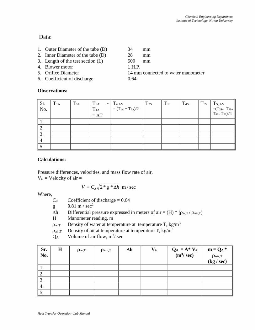
Data:
1. Outer Diameter of the tube (D) 34 mm
2. Inner Diameter of the tube (D) 28 mm
3. Length of the test section (L) 500 mm
4. Blower motor 1 H.P.
5. Orifice Diameter 14 mm connected to water manometer
6. Coefficient of discharge 0.64
Observations:
Sr.
No.
T1A T6A T6A -
T1A
= T
Ta AV = (T1A + T6A)/2
T2S T3S T4S T5S TS,,AV
=(T2S+ T3S+
T4S+ T5S) /4
1.
2.
3.
4.
5.
Calculations:
Pressure differences, velocities, and mass flow rate of air,
Va = Velocity of air =
Where,
Cd Coefficient of discharge = 0.64
g 9.81 m / sec2
h Differential pressure expressed in meters of air = (H) * (w,T / air,T)
H Manometer reading, m
w,T Density of water at temperature at temperature T, kg/m3
air,T Density of ait at temperature at temperature T, kg/m3
QA Volume of air flow, m3/ sec
Sr.
No.
H w,T air,T h Va QA = A* Va
(m3/ sec)
m = QA *
air,T
(kg / sec)
1.
2.
3.
4.
5.
sec / m **2 hgCV d
Chemical Engineering Department
Institute of Technology, Nirma University
Heat Transfer Operation- Lab Manual
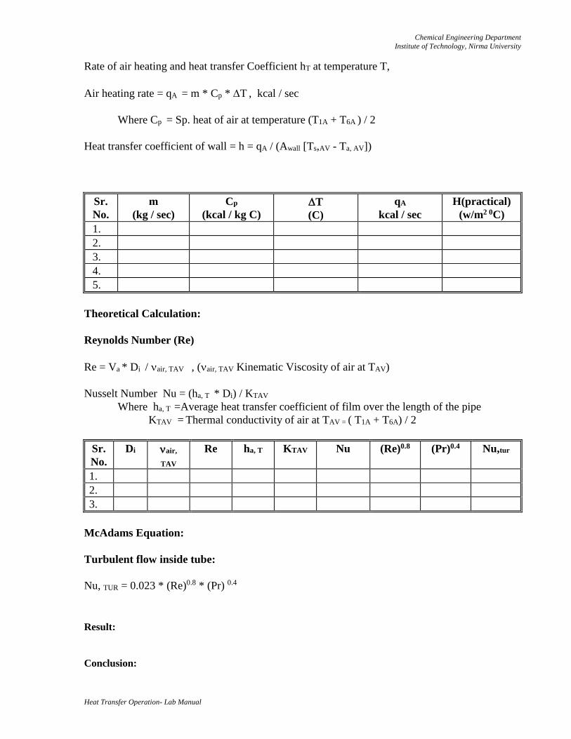
Rate of air heating and heat transfer Coefficient hT at temperature T,
Air heating rate = qA = m * Cp * T , kcal / sec
Where Cp = Sp. heat of air at temperature (T1A + T6A ) / 2
Heat transfer coefficient of wall = h = qA / (Awall [Ts,AV - Ta, AV])
Sr.
No.
m
(kg / sec)
Cp
(kcal / kg C)
T
(C)
qA
kcal / sec
H(practical)
(w/m2 0C)
1.
2.
3.
4.
5.
Theoretical Calculation:
Reynolds Number (Re)
Re = Va * Di / air, TAV , (air, TAV Kinematic Viscosity of air at TAV)
Nusselt Number Nu = (ha, T * Di) / KTAV
Where ha, T =Average heat transfer coefficient of film over the length of the pipe
KTAV = Thermal conductivity of air at TAV = ( T1A + T6A) / 2
Sr.
No.
Di air,
TAV
Re ha, T KTAV
Nu (Re)0.8 (Pr)0.4 Nu,tur
1.
2.
3.
McAdams Equation:
Turbulent flow inside tube:
Nu, TUR = 0.023 * (Re)0.8 * (Pr) 0.4
Result:
Conclusion:
Chemical Engineering Department
Institute of Technology, Nirma University
Heat Transfer Operation- Lab Manual
Quiz:
1. Why the heat transfer coefficient for natural convection is much less than that for forced
convection?
2. Why are heat transfer rates higher in turbulent flow inside a tube? Why?
3. Write the correlation that has been suggested for forced convection over a vertical plate or
cylinder in laminar or turbulent flow region.
Chemical Engineering Department
Institute of Technology, Nirma University
Heat Transfer Operation- Lab Manual
Date: Roll No:
Practical No:
EXTENDED SURFACE EQUIPMENT
Objective: After this experiment student will able to understand how to study the temperature
profile along with length in case of an extended surface.
Apparatus: Hot Plate with attached rod, dimmerstat, thermocouples.
Utility: Electric supply.
Theory:
When one of the two fluid streams has a much lower heat transfer coefficient than the other,
extended surface heat exchangers are used. In this exchangers , the outside area of the tube is
extended by fins, pegs, disks and other appendages and the outside area in contact with the fluid
thereby made much larger than the inside area .
Ui = ______1_______
1 + _ Ai_
hi Ao ho
This equation shows that if ho is small and hi is large , the value of Ui will be small , but
if A0 is made much larger than Ai , then Ui increases .
The temperature profile of extended surface is given by the following equation:
T - Ta = ( T0 - Ta) cos h [ m ( L : x ) ]-
cos h [ m L ]
_________
m = (h P / KA)
Where,
T0 = Temperature of the base plate.= Ts
Ta = Temperature of the ambient air = T∞
T = Temperature at distance x from base plate ( theoretical )
h = film coefficient of air
K = thermal conductivity of extended surface
L = Height of the extended surface
P = Perimeter of the extended surface
A = Area of cross section of the extended surface
Apparatus Description:
The apparatus consists of a hot plate with a M.S rod attached to the centre of the plate. A
groove is made at the centre of the plate and the M.S rod is joined to it. The temperature of the
hot plate can be varied by the dimmerstat. The temperature at various points of the rod is
measured by thermocouples. One thermocouple measures the ambient temperature of air.
Chemical Engineering Department
Institute of Technology, Nirma University
Heat Transfer Operation- Lab Manual
Apparatus Specifications:
Diameter of the rod , D = 25 mm.
Total length of the rod, L = 60 cm.
Distance between the thermocouple = 10 cm.
Procedure:
1. Switch on the power supply and adjust the dimmerstat to obtain the required heat input.
2. Keep the hot plate temperature at 250 0C maximum.
3. Wait until the steady state is reached, which is confirmed from the consistent temperature
readings T1 to T8 .
4. Measure the surface temperature at various points of the extended surfaces, base of the hot
plate and ambient temperature of air by rotating the selector switch.
5. Repeat the experiment at different heat inputs.
Precautions:
1. Keep dimmerstat to zero volt position before switching on the supply and then increase it
slowly.
2. Use proper range of ammeter and voltmeter.
3. Operate the selector switch of the temperature gently from 1 to 8.
4. Take the readings only when steady state is reached.
Data:
Thermal conductivity of M.S rod , K = 40 W / m.0K
Heat transfer coefficient of air , h = 0.4 W/m2. 0K
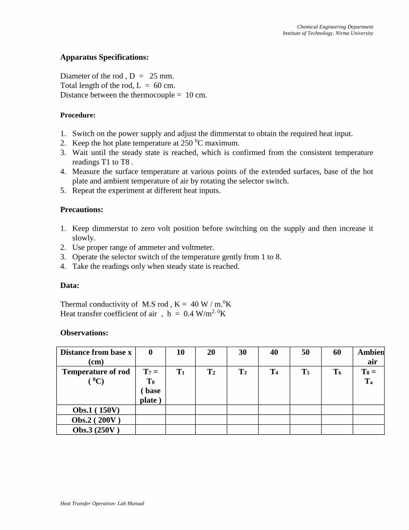
Observations:
Distance from base x
(cm)
0 10 20 30 40 50 60 Ambient
air
Temperature of rod
( 0C)
T7 =
T0
( base
plate )
T1 T2 T3 T4 T5 T6 T8 =
Ta
Obs.1 ( 150V)
Obs.2 ( 200V )
Obs.3 (250V )
Chemical Engineering Department
Institute of Technology, Nirma University
Heat Transfer Operation- Lab Manual
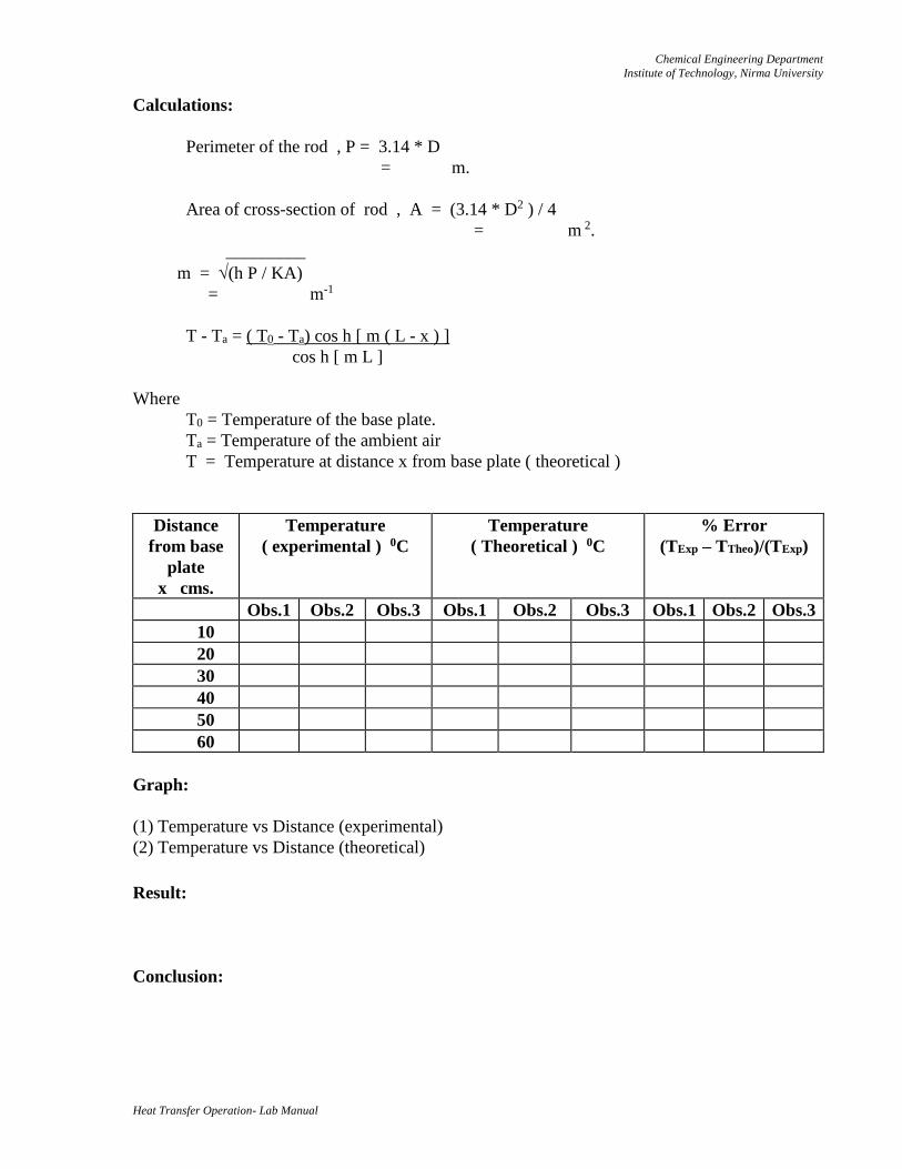
Calculations:
Perimeter of the rod , P = 3.14 * D
= m.
Area of cross-section of rod , A = (3.14 * D2 ) / 4
= m 2.
_________
m = (h P / KA)
= m-1
T - Ta = ( T0 - Ta) cos h [ m ( L - x ) ]
cos h [ m L ]
Where
T0 = Temperature of the base plate.
Ta = Temperature of the ambient air
T = Temperature at distance x from base plate ( theoretical )
Distance
from base
plate
x cms.
Temperature
( experimental ) 0C
Temperature
( Theoretical ) 0C
% Error
(TExp – TTheo)/(TExp)
Obs.1 Obs.2 Obs.3 Obs.1 Obs.2 Obs.3 Obs.1 Obs.2 Obs.3
10
20
30
40
50
60
Graph:
(1) Temperature vs Distance (experimental)
(2) Temperature vs Distance (theoretical)
Result:
Conclusion:
Chemical Engineering Department
Institute of Technology, Nirma University
Heat Transfer Operation- Lab Manual
Quiz:
1. Give a few practical and specific examples of use of fin in heat transfer.
2. How does a fins enhance heat transfer at a surface?
3. Mention the most common types of fins and sketch them.
4. Enumerate the various assumptions made in the formation of energy equation for one-
dimensional heat dissipation from an extended surface.
5. Fins are generally made of aluminium? Why?
Chemical Engineering Department
Institute of Technology, Nirma University
Heat Transfer Operation- Lab Manual
Date: Roll No:
Practical No:
PARALLEL FLOW HEAT EXCHANGER
Objective: After this experiment student will able to understand how to (1) determine overall
heat transfer coefficient for parallel flow pattern in double pipe heat exchanger (2) temperature
distribution in parallel flow heat exchanger.
Apparatus: Double pipe heat exchanger assembly, Geyser, Thermometers.
Utility: Water, Electric Supply.
Apparatus Description:
The apparatus consists of a tube in tube type (concentric) heat exchanger. The hot fluid (hot
water) obtained from an electric geyser flows through inner tube while the cold fluid (cold water)
flowing through the annulus.
The direction of hot water flow can not be altered while the direction of cold water can be altered
using valves so as to make the heat exchanger to function as parallel or counter flow heat
exchanger s shown in Figure 1.
The experiment is conducted by keeping the identical flow rates while running the unit as a
parallel flow and/or counter flow exchanger.
The temperatures are measured by mercury in glass thermometers and flow rates by graduated
measuring flasks and stop clock. The readings are recorded when the steady state is reached. The
outer tube is provided with adequate thermocol insulation to minimise the heat losses.
Procedure:
1. Place thermometers in the positions and note down their readings when they are at room
temperature and no water is flowing at either side this is required to correct the temperature.
2. Start the flow on hot water side.
3. Start the flow through annulus and run the exchanger as parallel flow unit. Put on the geyser.
4. Adjust the flow rate on hot water side, between the rate of 1.5-4.0 litre/ min.
5. Adjust the flow on cold water side between range of 3.0-8.0 litres/ min.
6. Keeping the flowrate same, wait till the steady state conditions are reached.
7. Record the temperatures on hot water and cold water side and also the flow rates accurately.
8. Repeat the experiment with a counter flow under identical flow conditions.
Observations:
1. Inner Tube Material: Copper I.D. (di) 10 mm O.D. (do ) 12 mm
2. Outer Tube Material: G. Iron I.D. (Di) 27.5 mm O.D. (Do ) 33.5 mm
3. Length of the heat exchanger (L) 2 m
Chemical Engineering Department
Institute of Technology, Nirma University
Heat Transfer Operation- Lab Manual
4. Thermal conductivity of copper (k) 30 kcal/h m 0C
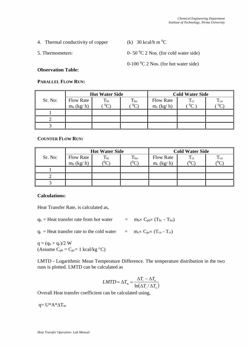
5. Thermometers: 0- 50 0C 2 Nos. (for cold water side)
0-100 0C 2 Nos. (for hot water side)
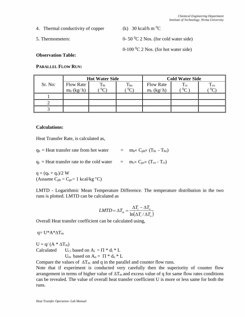
Observation Table:
PARALLEL FLOW RUN:
Hot Water Side Cold Water Side
Sr. No: Flow Rate
mh (kg/ h)
Thi
( 0C)
Tho
( 0C)
Flow Rate
mc (kg/ h)
Tci
( 0C )
Tco
( 0C)
1
2
3
Calculations:
Heat Transfer Rate, is calculated as,
qh = Heat transfer rate from hot water = mh Cph (Thi - Tho)
qc = Heat transfer rate to the cold water = mc Cpc (Tco - Tci)
q = (qh + qc)/2 W
(Assume Cph = Cpc= 1 kcal/kg C)
LMTD - Logarithmic Mean Temperature Difference. The temperature distribution in the two
runs is plotted. LMTD can be calculated as
Overall Heat transfer coefficient can be calculated using,
q= U*A*Tm
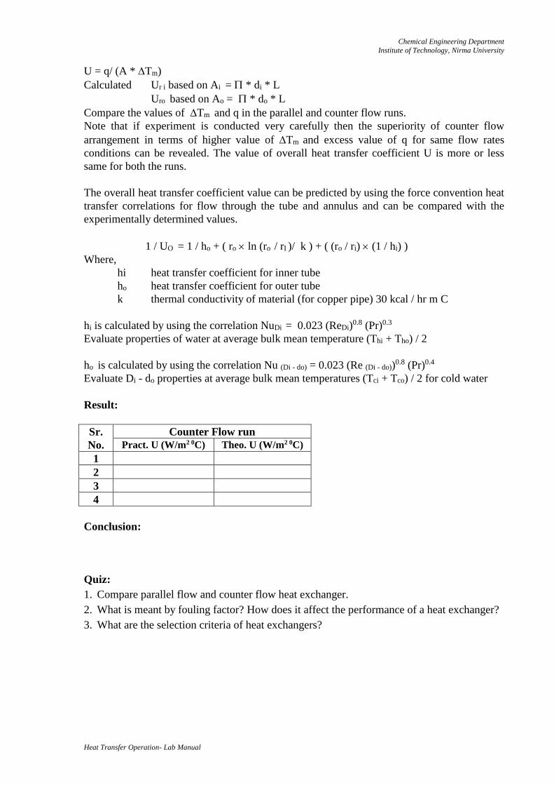
U = q/ (A * Tm)
Calculated Ur i based on Ai = * di * L
Uro based on Ao = * do * L
Compare the values of Tm and q in the parallel and counter flow runs.
Note that if experiment is conducted very carefully then the superiority of counter flow
arrangement in terms of higher value of Tm and excess value of q for same flow rates conditions
can be revealed. The value of overall heat transfer coefficient U is more or less same for both the
runs.
oi
oim
TT
TTTLMTD
/ln
Chemical Engineering Department
Institute of Technology, Nirma University
Heat Transfer Operation- Lab Manual
The overall heat transfer coefficient value can be predicted by using the force convention heat
transfer correlations for flow through the tube and annulus and can be compared with the
experimentally determined values.
1 / UO = 1 / ho + ( ro ln (ro / rI )/ k ) + ( (ro / ri) (1 / hi) )
Where,
hi heat transfer coefficient for inner tube
ho heat transfer coefficient for outer tube
k thermal conductivity of material (for copper pipe) 30 kcal / hr m C
hi is calculated by using the correlation NuDi = 0.023 (ReDi)0.8 (Pr)0.3
Evaluate properties of water at average bulk mean temperature (Thi + Tho) / 2
ho is calculated by using the correlation Nu (Di - do) = 0.023 (Re (Di - do))0.8 (Pr)0.4
Evaluate Di - do properties at average bulk mean temperatures (Tci + Tco) / 2 for cold water.
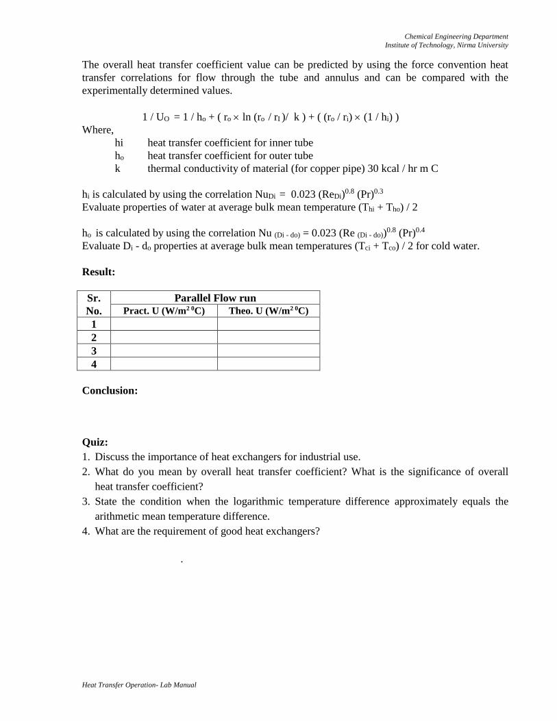
Result:
Sr.
No.
Parallel Flow run
Pract. U (W/m2 0C) Theo. U (W/m2 0C)
1
2
3
4
Conclusion:
Quiz:
1. Discuss the importance of heat exchangers for industrial use.
2. What do you mean by overall heat transfer coefficient? What is the significance of overall
heat transfer coefficient?
3. State the condition when the logarithmic temperature difference approximately equals the
arithmetic mean temperature difference.
4. What are the requirement of good heat exchangers?
.
Chemical Engineering Department
Institute of Technology, Nirma University
Heat Transfer Operation- Lab Manual
Date: Roll No:
Practical No:
COUNTER FLOW HEAT EXCHANGER
Objective: After this experiment student will able to understand how to (1) determine overall
heat transfer coefficient for counter flow pattern in double pipe heat exchanger
(2) temperature distribution in counter flow heat exchanger.
Apparatus: Double pipe heat exchanger assembly, Geyser, Thermometers.
Utility: Water, Electric Supply.
Apparatus Description:
The apparatus consists of a tube in tube type (concentric) heat exchanger. The hot fluid (hot
water) obtained from an electric geyser flows through inner tube while the cold fluid (cold
water) flowing through the annulus.
The direction of hot water flow cannot be altered while the direction of cold water can be
altered using valves so as to make the heat exchanger to function as parallel or counter flow
heat exchanger s shown in Figure 1.
The experiment is conducted by keeping the identical flow rates while running the unit as a
parallel flow exchanger and/or counter flow exchanger.
The temperatures are measured by mercury in glass thermometers and flow rates by graduated
measuring flasks and stop clock. The readings are recorded when the steady state is reached.
The outer tube is provided with adequate thermocol insulation to minimise the heat losses.
Procedure:
9. Place thermometers in the positions and note down their readings when they are at room
temperature and no water is flowing at either side this is required to correct the
temperature.
10. Start the flow on hot water side.
11. Start the flow through annulus and run the exchanger as parallel flow unit. Put on the
geyser.
12. Adjust the flow rate on hot water side, between the rate of 1.5-4.0 litre/ min.
13. Adjust the flow on cold water side between range of 3.0-8.0 litres/ min.
14. Keeping the flowrate same, wait till the steady state conditions are reached.
15. Record the temperatures on hot water and cold water side and also the flow rates
accurately.
16. Repeat the experiment with a counter flow under identical flow conditions.
Observations:
4. Inner Tube Material: Copper I.D. (di) 10 mm O.D. (do ) 12 mm
5. Outer Tube Material: G. Iron I.D. (Di) 27.5 mm O.D. (Do ) 33.5 mm
6. Length of the heat exchanger (L) 2 m
Chemical Engineering Department
Institute of Technology, Nirma University
Heat Transfer Operation- Lab Manual
4. Thermal conductivity of copper (k) 30 kcal/h m 0C
5. Thermometers: 0- 50 0C 2 Nos. (for cold water side)
0-100 0C 2 Nos. (for hot water side)
Observation Table:
PARALLEL FLOW RUN:
Hot Water Side Cold Water Side
Sr. No: Flow Rate
mh (kg/ h)
Thi
( 0C)
Tho
( 0C)
Flow Rate
mc (kg/ h)
Tci
( 0C )
Tco
( 0C)
1
2
3
COUNTER FLOW RUN:
Hot Water Side Cold Water Side
Sr. No: Flow Rate
mh (kg/ h)
Thi
(0C)
Tho
(0C)
Flow Rate
mc (kg/ h)
Tci
(0C)
Tco
(0C)
1
2
3
Calculations:
Heat Transfer Rate, is calculated as,
qh = Heat transfer rate from hot water = mh Cph (Thi - Tho)
qc = Heat transfer rate to the cold water = mc Cpc (Tco - Tci)
q = (qh + qc)/2 W
(Assume Cph = Cpc= 1 kcal/kg C)
LMTD - Logarithmic Mean Temperature Difference. The temperature distribution in the two
runs is plotted. LMTD can be calculated as
Overall Heat transfer coefficient can be calculated using,
q= U*A*Tm
oi
oim
TT
TTTLMTD
/ln
Chemical Engineering Department
Institute of Technology, Nirma University
Heat Transfer Operation- Lab Manual
U = q/ (A * Tm)
Calculated Ur i based on Ai = * di * L
Uro based on Ao = * do * L
Compare the values of Tm and q in the parallel and counter flow runs.
Note that if experiment is conducted very carefully then the superiority of counter flow
arrangement in terms of higher value of Tm and excess value of q for same flow rates
conditions can be revealed. The value of overall heat transfer coefficient U is more or less
same for both the runs.
The overall heat transfer coefficient value can be predicted by using the force convention heat
transfer correlations for flow through the tube and annulus and can be compared with the
experimentally determined values.
1 / UO = 1 / ho + ( ro ln (ro / rI )/ k ) + ( (ro / ri) (1 / hi) )
Where,
hi heat transfer coefficient for inner tube
ho heat transfer coefficient for outer tube
k thermal conductivity of material (for copper pipe) 30 kcal / hr m C
hi is calculated by using the correlation NuDi = 0.023 (ReDi)0.8 (Pr)0.3
Evaluate properties of water at average bulk mean temperature (Thi + Tho) / 2
ho is calculated by using the correlation Nu (Di - do) = 0.023 (Re (Di - do))0.8 (Pr)0.4
Evaluate Di - do properties at average bulk mean temperatures (Tci + Tco) / 2 for cold water
Result:
Sr.
No.
Counter Flow run
Pract. U (W/m2 0C) Theo. U (W/m2 0C)
1
2
3
4
Conclusion:
Quiz:
1. Compare parallel flow and counter flow heat exchanger.
2. What is meant by fouling factor? How does it affect the performance of a heat exchanger?
3. What are the selection criteria of heat exchangers?
Chemical Engineering Department
Institute of Technology, Nirma University
Heat Transfer Operation- Lab Manual
Date: Roll No:
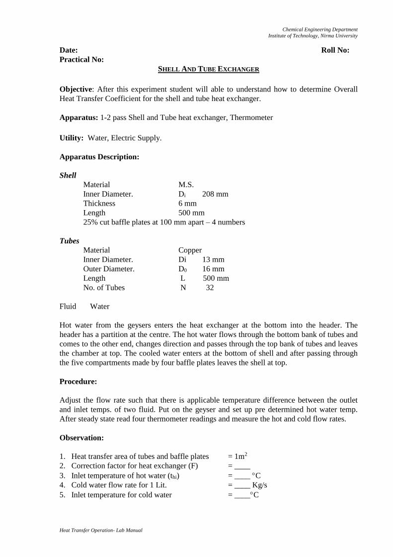
Practical No: SHELL AND TUBE EXCHANGER
Objective: After this experiment student will able to understand how to determine Overall
Heat Transfer Coefficient for the shell and tube heat exchanger.
Apparatus: 1-2 pass Shell and Tube heat exchanger, Thermometer
Utility: Water, Electric Supply.
Apparatus Description:
Shell
Material M.S.
Inner Diameter. Di 208 mm
Thickness 6 mm
Length 500 mm
25% cut baffle plates at 100 mm apart – 4 numbers
Tubes
Material Copper
Inner Diameter. Di 13 mm
Outer Diameter. D0 16 mm
Length L 500 mm
No. of Tubes N 32
Fluid Water
Hot water from the geysers enters the heat exchanger at the bottom into the header. The
header has a partition at the centre. The hot water flows through the bottom bank of tubes and
comes to the other end, changes direction and passes through the top bank of tubes and leaves
the chamber at top. The cooled water enters at the bottom of shell and after passing through
the five compartments made by four baffle plates leaves the shell at top.
Procedure:
Adjust the flow rate such that there is applicable temperature difference between the outlet
and inlet temps. of two fluid. Put on the geyser and set up pre determined hot water temp.
After steady state read four thermometer readings and measure the hot and cold flow rates.
Observation:
1. Heat transfer area of tubes and baffle plates = 1m2
2. Correction factor for heat exchanger (F) = ____
3. Inlet temperature of hot water (thi) = ____ C
4. Cold water flow rate for 1 Lit. = ____ Kg/s
5. Inlet temperature for cold water = ____C
Chemical Engineering Department
Institute of Technology, Nirma University
Heat Transfer Operation- Lab Manual
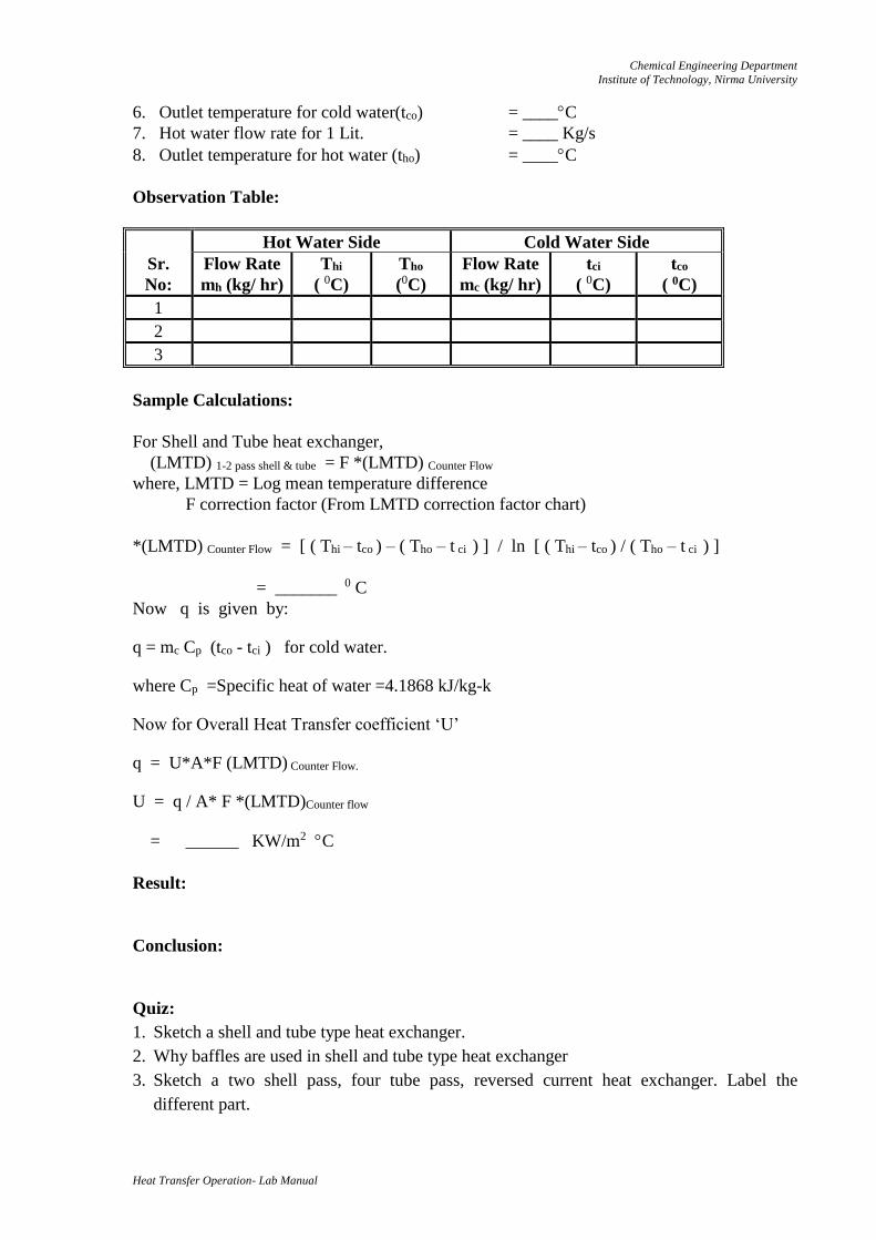
6. Outlet temperature for cold water(tco) = ____C
7. Hot water flow rate for 1 Lit. = ____ Kg/s
8. Outlet temperature for hot water (tho) = ____C
Observation Table:
Hot Water Side Cold Water Side
Sr.
No:
Flow Rate
mh (kg/ hr)
Thi
( 0C)
Tho
(0C)
Flow Rate
mc (kg/ hr)
tci
( 0C)
tco
( 0C)
1
2
3
Sample Calculations:
For Shell and Tube heat exchanger,
(LMTD) 1-2 pass shell & tube = F *(LMTD) Counter Flow
where, LMTD = Log mean temperature difference
F correction factor (From LMTD correction factor chart)
*(LMTD) Counter Flow = [ ( Thi – tco ) – ( Tho – t ci ) ] / ln [ ( Thi – tco ) / ( Tho – t ci ) ]
= _______ 0 C
Now q is given by:
q = mc Cp (tco - tci ) for cold water.
where Cp =Specific heat of water =4.1868 kJ/kg-k
Now for Overall Heat Transfer coefficient ‘U’
q = U*A*F (LMTD) Counter Flow.
U = q / A* F *(LMTD)Counter flow
= ______ KW/m2 C
Result:
Conclusion:
Quiz:
1. Sketch a shell and tube type heat exchanger.
2. Why baffles are used in shell and tube type heat exchanger
3. Sketch a two shell pass, four tube pass, reversed current heat exchanger. Label the
different part.
Chemical Engineering Department
Institute of Technology, Nirma University
Heat Transfer Operation- Lab Manual
Date: Roll No:
Practical No:
FINNED TUBE HEAT EXCHANGER
Objective: After this experiment student will able to understand how to study and compare
temperature distribution, heat transfer rate, overall heat transfer coefficient of the finned tube
heat exchanger.
Apparatus: Stop clock, measuring flask, thermometers.
Utility: Water, electricity supply.
Theory:
Finned tube heat exchangers are used when there is a huge difference between the values of
the heat transfer coefficients of the fluids involved e.g. heat transfer between air and water. So
to increase the total transmission of heat, extended surfaces like fins are added. The fins are
of many types like longitudinal, transverse, pegs or studs, spines etc.
Apparatus description:
The apparatus consists of a concentric tube heat exchanger. The hot fluid i.e. Hot water is
obtained from an electric geyser and it flows through the inner finned tube, in both directions.
The direction can be changed by operating different valves. The cold air is admitted through
one end. Temperatures of the fluids can be measured using stop and measuring flask. The
outer tube is provided with adequate asbestos rope insulation to minimise the heat loss to the
surrounding.
Apparatus Specification:
Length of the heat exchanger = 1m
Inner copper finned tube I.D = 0.016 m, O.D = 0.02 m with longitudinal fin 0.022m height
and 1m. long.
Total number of fins = 8
Outer tube, I.D = 0.064 m, O.D = 0.075 m
Fin thickness = 0.00166 m
Annulus flow area = 1.288 m2
Perimeter of the fin = 0.4016 m
Procedure:
Keep the thermometers in position.
Start the hot water flow. Start the flow of cold air.
Put on the electric geyser.
Adjust the flow rate on hot water side (approx.: 500 ml/min.) .Keep the flow rate same till
the steady state condition is reached.
Note the temperatures and measure the flow rate.
Repeat the experiment for different flow rates.
Chemical Engineering Department
Institute of Technology, Nirma University
Heat Transfer Operation- Lab Manual
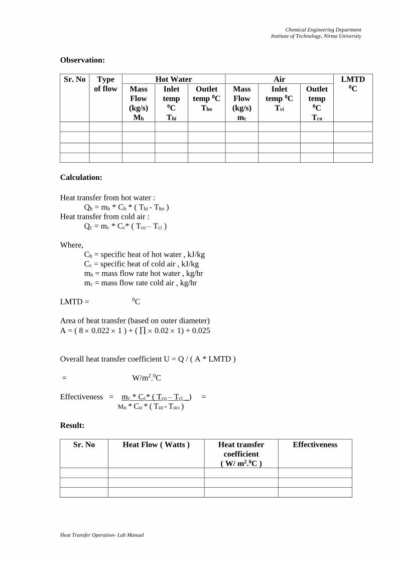
Observation:
Sr. No Type
of flow
Hot Water Air LMTD 0C Mass
Flow
(kg/s)
Mh
Inlet
temp 0C
Thi
Outlet
temp 0C
Tho
Mass
Flow
(kg/s)
mc
Inlet
temp 0C
Tci
Outlet
temp 0C
Tco
Calculation:
Heat transfer from hot water :
Qh = mh * Ch * ( Thi - Tho )
Heat transfer from cold air :
Qc = mc * Cc* ( Tco – Tci )
Where,
Ch = specific heat of hot water , kJ/kg
Cc = specific heat of cold air , kJ/kg
mh = mass flow rate hot water , kg/hr
mc = mass flow rate cold air , kg/hr
LMTD = 0C
Area of heat transfer (based on outer diameter)
A = ( 8 0.022 1 ) + ( 0.02 1) + 0.025
Overall heat transfer coefficient U = Q / ( A * LMTD )
= W/m2.0C
Effectiveness = mc * Cc* ( Tco – Tci _) =
MH * CH * ( THI - THO )
Result:
Sr. No Heat Flow ( Watts ) Heat transfer
coefficient
( W/ m2.0C )
Effectiveness

Chemical Engineering Department
Institute of Technology, Nirma University
Heat Transfer Operation- Lab Manual
Quiz:
1. What are the advantages of finned tube heat exchanger?
2. Give applications of finned tube heat exchanger.
3. Define effectiveness and number of transfer units in the context of heat exchanges.

Chemical Engineering Department
Institute of Technology, Nirma University
Heat Transfer Operation- Lab Manual
Date: Roll No:
Practical No: EMISSIVITY MEASUREMENT APPARATUS
Objective: After this experiment student will able to understand how to determine emissivity
of test plate.
Apparatus: Black plate, Test plate (aluminium)
Theory:
All the bodies emit and absorb the thermal radiation to and from surroundings. The rate of
thermal radiation depends upon the temperature of body. Thermal radiation is electromagnetic
wave and does not require any material medium for propagation.
When thermal radiation strikes a body, part of it is reflected, part of it is absorbed and part of
it is transmitted through body.
The fraction of incident energy, reflected by the surface is called reflectivity ().
The fraction of incident energy, absorbed by the surface is called absorptivity ().
The fraction of incident energy transmitted through body is called transmissivity ( ).
The surface which absorbs all the incident radiation is called a black surface.
FOR A BLACK SURFACE (=1)
The radiant flux, emitted from the surface is called emissive power (e).
The emissivity of a surface is ratio of emissive power of a surface to that of black surface at
the same temperature.
Construction of apparatus:
The apparatus uses comparator method for determining the emissivity of test plate. It consists
of two aluminium plates, of equal physical dimensions. Mica heaters are provided inside the
plates. The plates are mounted in an enclosure to provide undisturbed surroundings.
One of the plates is blackened outside for use as a compurgator because black surface has
=1. Another plate is having natural surface finish. Input to heaters can be controlled by
separate dimmerstats. Heater input is measured on common ammeter and voltmeter. One
thermocouple is fitted on surface of each plate to measure the surface temperature with digital
temperature indicator. By adjusting input to the heaters, both the plates are brought to the
same temperature, so that conduction and convection losses from both the plates are equal
and difference in input is due to different emissivity.
Holes are provided at backside bottom and at the top of enclosure for natural circulation of air
over the plates.
The plate enclosure is provided with Perspex acrylic sheet at the front. Thus, =e/eb
Chemical Engineering Department
Institute of Technology, Nirma University
Heat Transfer Operation- Lab Manual
Procedure:
1. Blacken one of the plates with the help of lamp black (normally this is blackened at the
works, but if blacking is wiped out, then blackening is necessary)
2. Keep both the dimmer Knobs at ZERO position.
3. Insert the supply pin-top in the socket (which is properly earthen) and switch ON the main
supply.
4. Switch ON the main switch on the panel.
5. Switch the meter selector switch (toggle switch) in downward position.
6. Adjust dimmer of black plate, so that around 110-120 volts are supplied to black plate.
7. Now, switch the meter selector switch in upward position.
8. Adjust test plate voltage slightly less than that of black plate (says 100- 110 volts)
9. Check the temperature (after, say 10 minutes) and adjust the dimmers so that temperature
of both the plates are equal and steady. Normally, very minor adjustments are required for
this.
10. Note down the readings after the plate temperatures reach steady state.
Precautions:
1. Black plate should be perfectly blackened
2. Never put your hand or papers over the holes provided at the top of enclosure.
3. Keep at least 200 mm distance between the back side of unit and wall
Operate all the switches sand
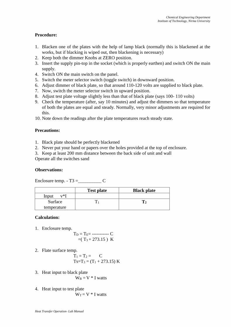
Observations:
Enclosure temp. - T3 =__________ C
Calculation:
1. Enclosure temp.
TD = TE= ----------- C
=( T3 + 273.15 ) K
2. Flate surface temp.
T1 = T2 = C
Ts=T3 = (T1 + 273.15) K
3. Heat input to black plate
WB = V * I watts
4. Heat input to test plate
WT = V * I watts
Test plate Black plate
Input v*I
Surface
temperature
T1 T2
Chemical Engineering Department
Institute of Technology, Nirma University
Heat Transfer Operation- Lab Manual
5. Surface area of plates
A = 2* /4{D2 + (.D.t)}
=0.0447 m2
Where,
D= dia. of plates=0.16 m
And t= thickness of plates = 0.009 m
6. For black plate
WB = WCVB+WCDB+WRB -------------------(I)
Where,
WCVB = Convection losses
WCDB= Conduction losses
WRB = Radiation losses
Similarly, for test plate,
WT=WCVT+WCDB+WRT ----------------(ii)
As both plates are of same physical dimensions, same material and at same temperature.
WCVB = WCVT and WCDB = WCDT
Subtracting equation (ii) from (i), we get
WB _- WT = WRB - WRT
= [ A B(TS4 - TD
4)]- [ A T(TS4 - TD
4)]
= A (TS4 - TD
4)( B-T)
As emissivity of black plate is 1.
WB-WT = A (TS4 - TD
4) (1-T)
Where,
T =Emissivity of test plate
= Stefan Boltzmann constant
= 5.667*10-8 W/m2 K4
Result:
The emissivity of test plate was found to be ___________at the temperature of __________
K Conclusion:
Quiz:
1. Explain the mechanism of radiation heat transfer
2. Differentiate between the radiation heat transfer and conduction / convection heat transfer
combined.
3. Define a black body. Give examples of some surfaces which do not appear black but have
high value of absorptivities.
4. Two pieces of wood are placed in sunlight; one piece is painted white and the other black.
Which piece will absorb more heat?
Chemical Engineering Department
Institute of Technology, Nirma University
Heat Transfer Operation- Lab Manual
Date: Roll No:
Practical No: DROP WISE AND FILM WISE CONDENSATION APPARATUS
Objective: After this experiment student will able to understand how to study the dropwise
and filmwise condensation phenomena.
Apparatus: Condensers, main unit, heating elements, temperature indicator, rota meter,
pressure gauge
Apparatus Description:
Condensers:
One chromium plated for dropwise condensation and one natural finish for filmwise
condensation otherwise identical in construction.
Dimensions: 15 cm dia.*12 cm length
Surface area: cm2
Fabricated from copper with reverse flow in concentric tubes Fitted with thermocouple for
surface temp. Measurements
Main unit:
M.S. fabricated construction comprising test section and steam generation section. Test
section provided with glass converse on front and rear sides of test section for visualisation of
the process.
Heating elements:
1.5KW water heater operated through 30 amps D.P.switch
Procedure:
1. Fill up the water in the main unit through bottom valve upto the sight glass fitted on the
unit.
2. After filling the water close the valve. Start the water flow rate through one of the
condensers which is to be tested and note water flow rate in the rotameter. Ensure that
during measurement water is flowing only through the condenser under test and second
valve is closed.
3. Connect supply socket to the mains and switch on the heater.
4. Slowly steam generation will start in the bottom portion of the unit and as the steam rises
to test section and get condensed on the tube and fells back in the trough.
5. Depending upon the type of condenser under test dropwise or filmwise condensation can
be visualised.
6. If water flow rate is low than steam pressure in chamber will rise and pressure gauge will
read the pressure.
7. If the water flow rate is matched than condensation will occur at more or less at
atmospheric pressure.
8. Process of dropwise and filmwise condensation can be easily viewed through the front
glass window of main unit.
Chemical Engineering Department
Institute of Technology, Nirma University
Heat Transfer Operation- Lab Manual
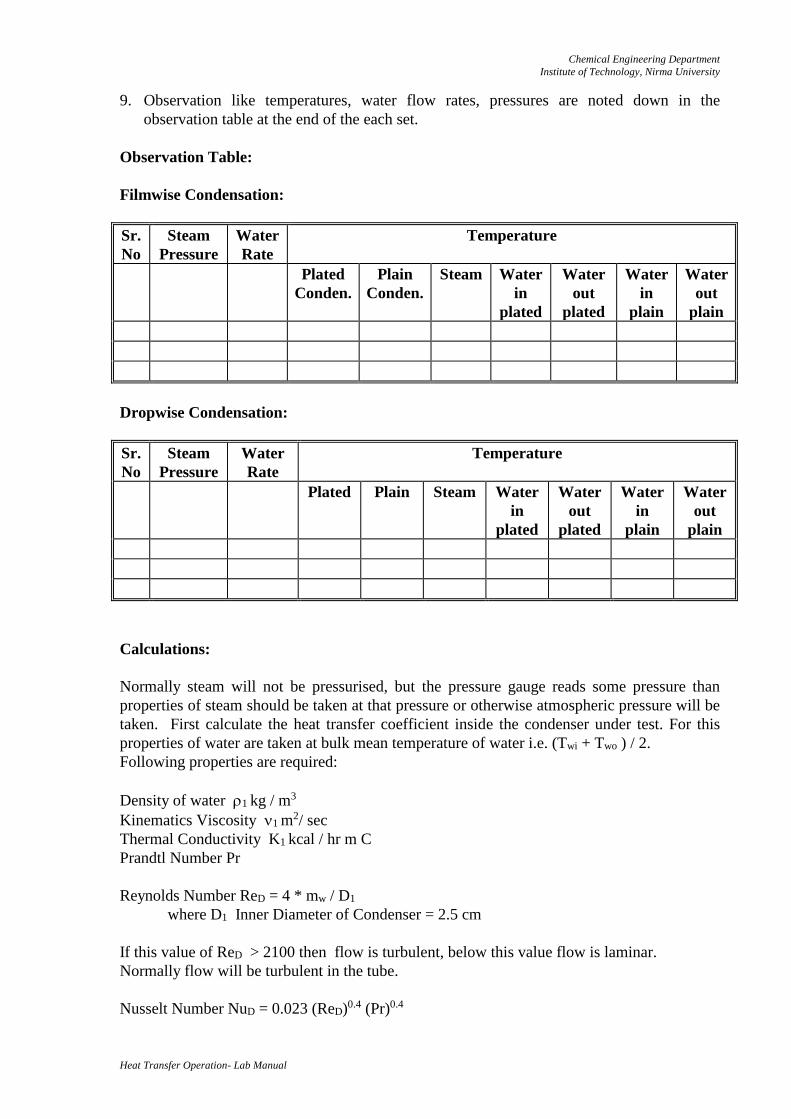
9. Observation like temperatures, water flow rates, pressures are noted down in the
observation table at the end of the each set.
Observation Table:
Filmwise Condensation:
Sr.
No
Steam
Pressure
Water
Rate
Temperature
Plated
Conden.
Plain
Conden.
Steam Water
in
plated
Water
out
plated
Water
in
plain
Water
out
plain
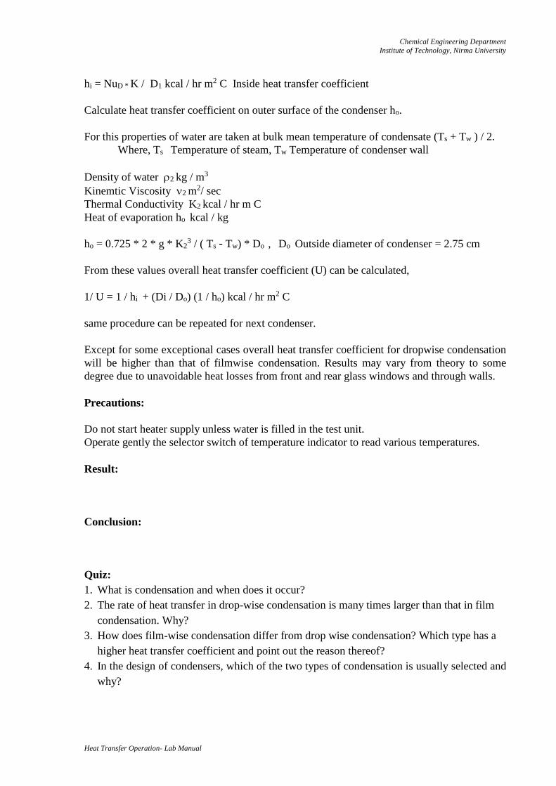
Dropwise Condensation:
Sr.
No
Steam
Pressure
Water
Rate
Temperature
Plated Plain Steam Water
in
plated
Water
out
plated
Water
in
plain
Water
out
plain
Calculations:
Normally steam will not be pressurised, but the pressure gauge reads some pressure than
properties of steam should be taken at that pressure or otherwise atmospheric pressure will be
taken. First calculate the heat transfer coefficient inside the condenser under test. For this
properties of water are taken at bulk mean temperature of water i.e. (Twi + Two ) / 2.
Following properties are required:
Density of water 1 kg / m3
Kinematics Viscosity 1 m2/ sec
Thermal Conductivity K1 kcal / hr m C
Prandtl Number Pr
Reynolds Number ReD = 4 * mw / D1
where D1 Inner Diameter of Condenser = 2.5 cm
If this value of ReD > 2100 then flow is turbulent, below this value flow is laminar.
Normally flow will be turbulent in the tube.
Nusselt Number NuD = 0.023 (ReD)0.4 (Pr)0.4
Chemical Engineering Department
Institute of Technology, Nirma University
Heat Transfer Operation- Lab Manual
hi = NuD * K / D1 kcal / hr m2 C Inside heat transfer coefficient
Calculate heat transfer coefficient on outer surface of the condenser ho.
For this properties of water are taken at bulk mean temperature of condensate (Ts + Tw ) / 2.
Where, Ts Temperature of steam, Tw Temperature of condenser wall
Density of water 2 kg / m3
Kinemtic Viscosity 2 m2/ sec
Thermal Conductivity K2 kcal / hr m C
Heat of evaporation ho kcal / kg
ho = 0.725 * 2 * g * K23 / ( Ts - Tw) * Do , Do Outside diameter of condenser = 2.75 cm
From these values overall heat transfer coefficient (U) can be calculated,
1/ U = 1 / hi + (Di / Do) (1 / ho) kcal / hr m2 C
same procedure can be repeated for next condenser.
Except for some exceptional cases overall heat transfer coefficient for dropwise condensation
will be higher than that of filmwise condensation. Results may vary from theory to some
degree due to unavoidable heat losses from front and rear glass windows and through walls.
Precautions:
Do not start heater supply unless water is filled in the test unit.
Operate gently the selector switch of temperature indicator to read various temperatures.
Result:
Conclusion:
Quiz:
1. What is condensation and when does it occur?
2. The rate of heat transfer in drop-wise condensation is many times larger than that in film
condensation. Why?
3. How does film-wise condensation differ from drop wise condensation? Which type has a
higher heat transfer coefficient and point out the reason thereof?
4. In the design of condensers, which of the two types of condensation is usually selected and
why?