heat exchanger
DESCRIPTION
heat ExchangerTRANSCRIPT
Ensuring the reliability of Aluminium Plate-Fin Heat ExchangersDavid Averous, Florian Picard and Gilles Aubert, Fives Cryo France
ABSTRACT
Aluminium Brazed Plate Fin Heat Exchangers have been frequently used in the cryogenics industry, in particular in gas processing applications such as LNG plants. The complex technology of Brazed Aluminium Plate-Fin Heat Exchangers (BAHX) offers a high-level heat transfer capacity and a large range of allowable pressures, but requires highly skilled design in return.
Optimal design leads to some difficulties due to the fact that any hydraulic or thermal perturbation on a stream is directly propagated to the others through the aluminium core matrix, and could also directly impact the mechanical integrity of the exchanger. This is particularly applicable to off-design and nonsteady state conditions.
The paper focuses on the implementation of technical resources in order to provide accurate expertise for the operation of BAHXs, including thermo-hydraulic analysis and mechanical stress studies. Inhouse computational tools are used to highlight the physical phenomena which are inherent to the behavior of BAHXs.
Therefore, the reliability of BAHXs is directly based on such calculations in order to define and continuously improve the standard design rules.
INTRODUCTION
Brazed Aluminium Plate-fin heat exchangers (BAHXs) are widely used in process industries such as gas processing and petrochemical industries including cryogenic applications: industrial gases and hydrocarbon separation are the most common ones, but many processes use this type of equipment, including recovery of natural gas liquids, helium refrigerators and liquefiers, hydrogen purification, ammonia and ethylene processes, nuclear engineering and synthetic gas production.
Maximizing thermal efficiency with high reliability is the main objective for such cryogenic processes. BAHXs promote exchange between many streams simultaneously (cases with more than 12 streams are common) allowing to save energy very efficiently.
However any perturbation on a stream entering the BAHX is propagated to the other streams and, as a result, has an influence on all duties of its immediate surroundings. The comprehension of local and global thermal stresses within BAHXs constitutes a primary objective to reduce the possibility of component damage or failure during operation.
This document presents some keys both to prevent failure during operation, and also to offer the optimal design according to drastic customers' requirements.
GENERAL DESCRIPTION AND NOMENCLATURE
Introduction
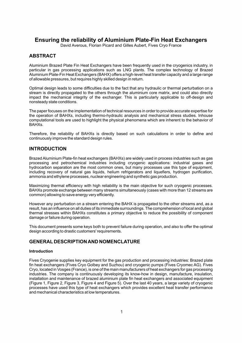
Fives Cryogenie supplies key equipment for the gas production and processing industries: Brazed plate fin heat exchangers (Fives Cryo Golbey and Suzhou) and cryogenic pumps (Fives Cryomec AG). Fives Cryo, located in Vosges (France), is one of the main manufacturers of heat exchangers for gas processing industries. The company is continuously developing its know-how in design, manufacture, insulation, installation and maintenance of brazed aluminium plate fin heat exchangers and associated equipment (Figure 1, Figure 2, Figure 3, Figure 4 and Figure 5). Over the last 40 years, a large variety of cryogenic processes have used this type of heat exchangers which provides excellent heat transfer performance and mechanical characteristics at low temperatures.
1
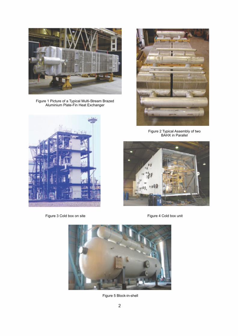
Figure 1 Picture of a Typical Multi-Stream BrazedAluminium Plate-Fin Heat Exchanger
Figure 3 Cold box on site
Figure 2 Typical Assembly of two BAHX in Parallel
Figure 4 Cold box unit
Figure 5 Block-in-shell
2
Description
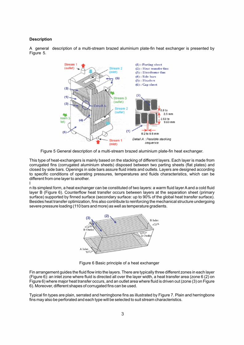
A general description of a multi-stream brazed aluminium plate-fin heat exchanger is presented by Figure 5.
Figure 5 General description of a multi-stream brazed aluminium plate-fin heat exchanger.
This type of heat-exchangers is mainly based on the stacking of different layers. Each layer is made from corrugated fins (corrugated aluminium sheets) disposed between two parting sheets (flat plates) and closed by side bars. Openings in side bars assure fluid inlets and outlets. Layers are designed according to specific conditions of operating pressures, temperatures and fluids characteristics, which can be different from one layer to another.In its simplest form, a heat exchanger can be constituted of two layers: a warm fluid layer A and a cold fluid layer B (Figure 6). Counterflow heat transfer occurs between layers at the separation sheet (primary surface) supported by finned surface (secondary surface: up to 90% of the global heat transfer surface). Besides heat transfer optimization, fins also contribute to reinforcing the mechanical structure undergoing severe pressure loading (110 bars and more) as well as temperature gradients.
Figure 6 Basic principle of a heat exchanger
Fin arrangement guides the fluid flow into the layers. There are typically three different zones in each layer (Figure 6): an inlet zone where fluid is directed all over the layer width, a heat transfer area (zone 6 (2) on Figure 6) where major heat transfer occurs, and an outlet area where fluid is driven out (zone (3) on Figure 6). Moreover, different shapes of corrugated fins can be used.
Typical fin types are plain, serrated and herringbone fins as illustrated by Figure 7. Plain and herringbone fins may also be perforated and each type will be selected to suit stream characteristics.
3
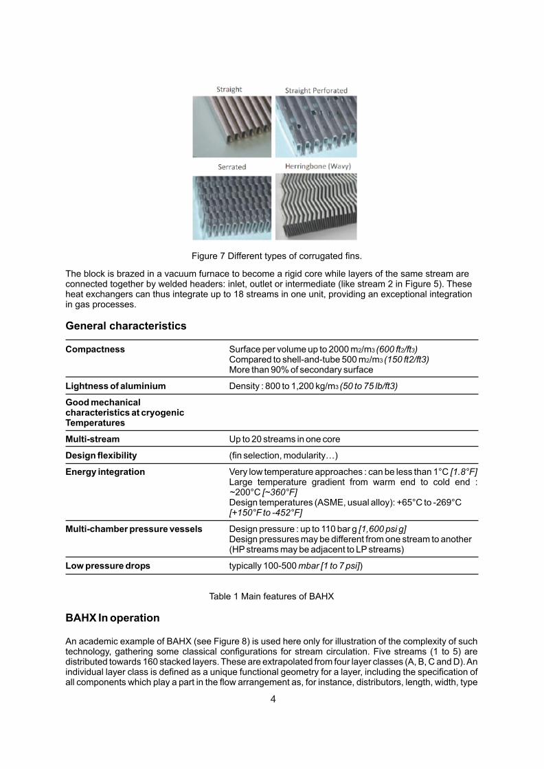
Figure 7 Different types of corrugated fins.
The block is brazed in a vacuum furnace to become a rigid core while layers of the same stream areconnected together by welded headers: inlet, outlet or intermediate (like stream 2 in Figure 5). Theseheat exchangers can thus integrate up to 18 streams in one unit, providing an exceptional integrationin gas processes.
General characteristics
Compactness Surface per volume up to 2000 m2/m3 (600 ft2/ft3)Compared to shell-and-tube 500 m2/m3 (150 ft2/ft3)More than 90% of secondary surface
Lightness of aluminium Density : 800 to 1,200 kg/m3 (50 to 75 lb/ft3)
Good mechanicalcharacteristics at cryogenicTemperatures
Multi-stream Up to 20 streams in one core
Design flexibility (fin selection, modularity…)
Energy integration Very low temperature approaches : can be less than 1°C [1.8°F]Large temperature gradient from warm end to cold end : ~200°C [~360°F]Design temperatures (ASME, usual alloy): +65°C to -269°C[+150°F to -452°F]
Multi-chamber pressure vessels Design pressure : up to 110 bar g [1,600 psi g]Design pressures may be different from one stream to another(HP streams may be adjacent to LP streams)
Low pressure drops typically 100-500 mbar [1 to 7 psi])
Table 1 Main features of BAHX
BAHX In operation
An academic example of BAHX (see Figure 8) is used here only for illustration of the complexity of such technology, gathering some classical configurations for stream circulation. Five streams (1 to 5) are distributed towards 160 stacked layers. These are extrapolated from four layer classes (A, B, C and D). An individual layer class is defined as a unique functional geometry for a layer, including the specification of all components which play a part in the flow arrangement as, for instance, distributors, length, width, type
4
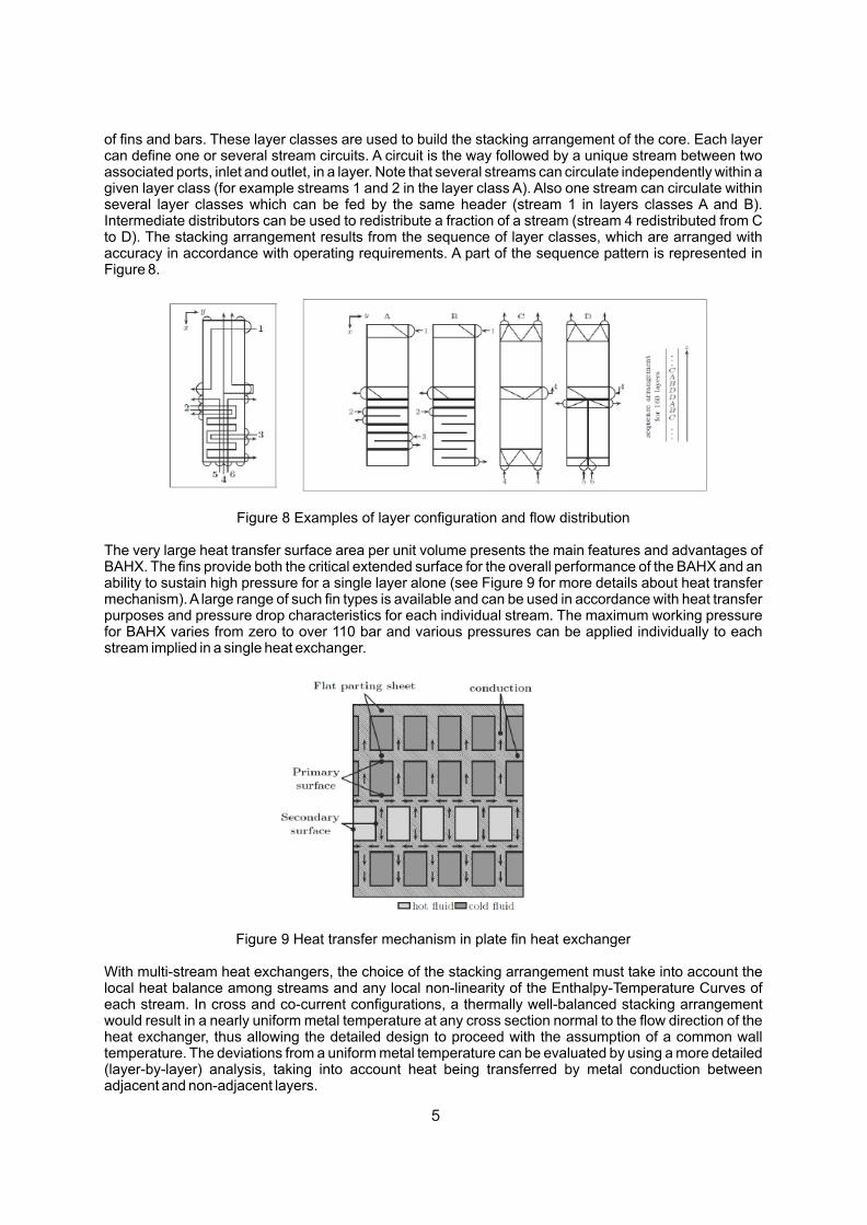
of fins and bars. These layer classes are used to build the stacking arrangement of the core. Each layer can define one or several stream circuits. A circuit is the way followed by a unique stream between two associated ports, inlet and outlet, in a layer. Note that several streams can circulate independently within a given layer class (for example streams 1 and 2 in the layer class A). Also one stream can circulate within several layer classes which can be fed by the same header (stream 1 in layers classes A and B). Intermediate distributors can be used to redistribute a fraction of a stream (stream 4 redistributed from C to D). The stacking arrangement results from the sequence of layer classes, which are arranged with accuracy in accordance with operating requirements. A part of the sequence pattern is represented in Figure 8.
Figure 8 Examples of layer configuration and flow distribution
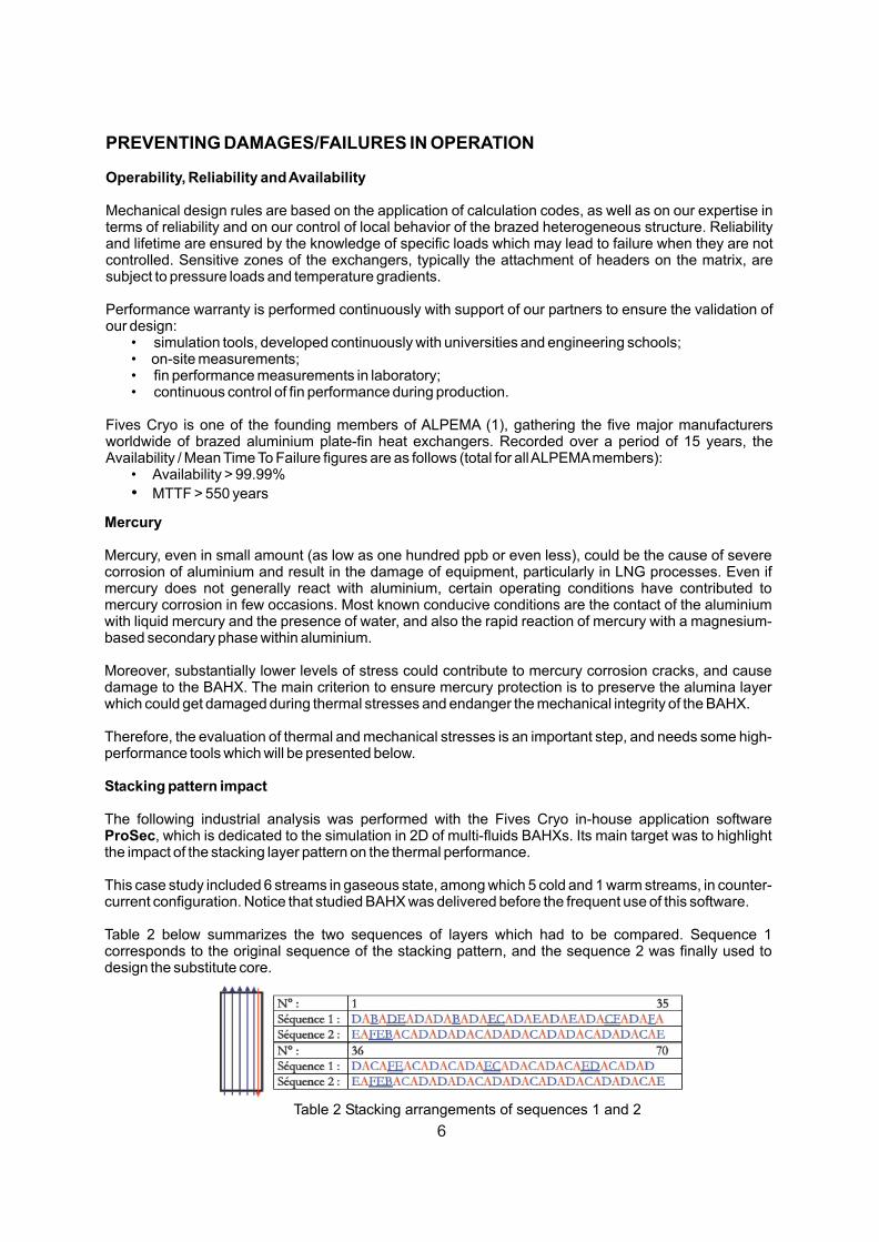
The very large heat transfer surface area per unit volume presents the main features and advantages of BAHX. The fins provide both the critical extended surface for the overall performance of the BAHX and an ability to sustain high pressure for a single layer alone (see Figure 9 for more details about heat transfer mechanism). A large range of such fin types is available and can be used in accordance with heat transfer purposes and pressure drop characteristics for each individual stream. The maximum working pressure for BAHX varies from zero to over 110 bar and various pressures can be applied individually to each stream implied in a single heat exchanger.
Figure 9 Heat transfer mechanism in plate fin heat exchanger
With multi-stream heat exchangers, the choice of the stacking arrangement must take into account the local heat balance among streams and any local non-linearity of the Enthalpy-Temperature Curves of each stream. In cross and co-current configurations, a thermally well-balanced stacking arrangement would result in a nearly uniform metal temperature at any cross section normal to the flow direction of the heat exchanger, thus allowing the detailed design to proceed with the assumption of a common wall temperature. The deviations from a uniform metal temperature can be evaluated by using a more detailed (layer-by-layer) analysis, taking into account heat being transferred by metal conduction between adjacent and non-adjacent layers.
5
PREVENTING DAMAGES/FAILURES IN OPERATION
Operability, Reliability and Availability
Mechanical design rules are based on the application of calculation codes, as well as on our expertise in terms of reliability and on our control of local behavior of the brazed heterogeneous structure. Reliability and lifetime are ensured by the knowledge of specific loads which may lead to failure when they are not controlled. Sensitive zones of the exchangers, typically the attachment of headers on the matrix, are subject to pressure loads and temperature gradients.
Performance warranty is performed continuously with support of our partners to ensure the validation of our design:
• simulation tools, developed continuously with universities and engineering schools;• on-site measurements;• fin performance measurements in laboratory;• continuous control of fin performance during production.
Fives Cryo is one of the founding members of ALPEMA (1), gathering the five major manufacturers worldwide of brazed aluminium plate-fin heat exchangers. Recorded over a period of 15 years, the Availability / Mean Time To Failure figures are as follows (total for all ALPEMA members):
• Availability > 99.99%
• MTTF > 550 years
Mercury
Mercury, even in small amount (as low as one hundred ppb or even less), could be the cause of severe corrosion of aluminium and result in the damage of equipment, particularly in LNG processes. Even if mercury does not generally react with aluminium, certain operating conditions have contributed to mercury corrosion in few occasions. Most known conducive conditions are the contact of the aluminium with liquid mercury and the presence of water, and also the rapid reaction of mercury with a magnesium-based secondary phase within aluminium.
Moreover, substantially lower levels of stress could contribute to mercury corrosion cracks, and cause damage to the BAHX. The main criterion to ensure mercury protection is to preserve the alumina layer which could get damaged during thermal stresses and endanger the mechanical integrity of the BAHX.
Therefore, the evaluation of thermal and mechanical stresses is an important step, and needs some high-performance tools which will be presented below.
Stacking pattern impact
The following industrial analysis was performed with the Fives Cryo in-house application software ProSec, which is dedicated to the simulation in 2D of multi-fluids BAHXs. Its main target was to highlight the impact of the stacking layer pattern on the thermal performance.
This case study included 6 streams in gaseous state, among which 5 cold and 1 warm streams, in counter-current configuration. Notice that studied BAHX was delivered before the frequent use of this software.
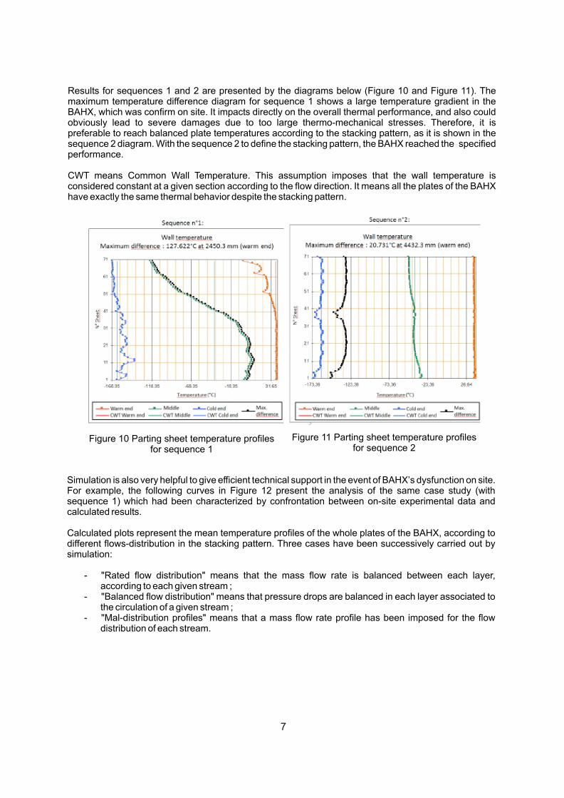
Table 2 below summarizes the two sequences of layers which had to be compared. Sequence 1 corresponds to the original sequence of the stacking pattern, and the sequence 2 was finally used to design the substitute core.
Table 2 Stacking arrangements of sequences 1 and 2
6
Results for sequences 1 and 2 are presented by the diagrams below (Figure 10 and Figure 11). The maximum temperature difference diagram for sequence 1 shows a large temperature gradient in the BAHX, which was confirm on site. It impacts directly on the overall thermal performance, and also could obviously lead to severe damages due to too large thermo-mechanical stresses. Therefore, it is preferable to reach balanced plate temperatures according to the stacking pattern, as it is shown in the sequence 2 diagram. With the sequence 2 to define the stacking pattern, the BAHX reached the specified performance.
CWT means Common Wall Temperature. This assumption imposes that the wall temperature is considered constant at a given section according to the flow direction. It means all the plates of the BAHX have exactly the same thermal behavior despite the stacking pattern.
Figure 10 Parting sheet temperature profiles for sequence 1
Figure 11 Parting sheet temperature profiles for sequence 2
Simulation is also very helpful to give efficient technical support in the event of BAHX’s dysfunction on site. For example, the following curves in Figure 12 present the analysis of the same case study (with sequence 1) which had been characterized by confrontation between on-site experimental data and calculated results.
Calculated plots represent the mean temperature profiles of the whole plates of the BAHX, according to different flows-distribution in the stacking pattern. Three cases have been successively carried out by simulation:
- "Rated flow distribution" means that the mass flow rate is balanced between each layer, according to each given stream ;
- "Balanced flow distribution" means that pressure drops are balanced in each layer associated to the circulation of a given stream ;
- "Mal-distribution profiles" means that a mass flow rate profile has been imposed for the flow distribution of each stream.
7
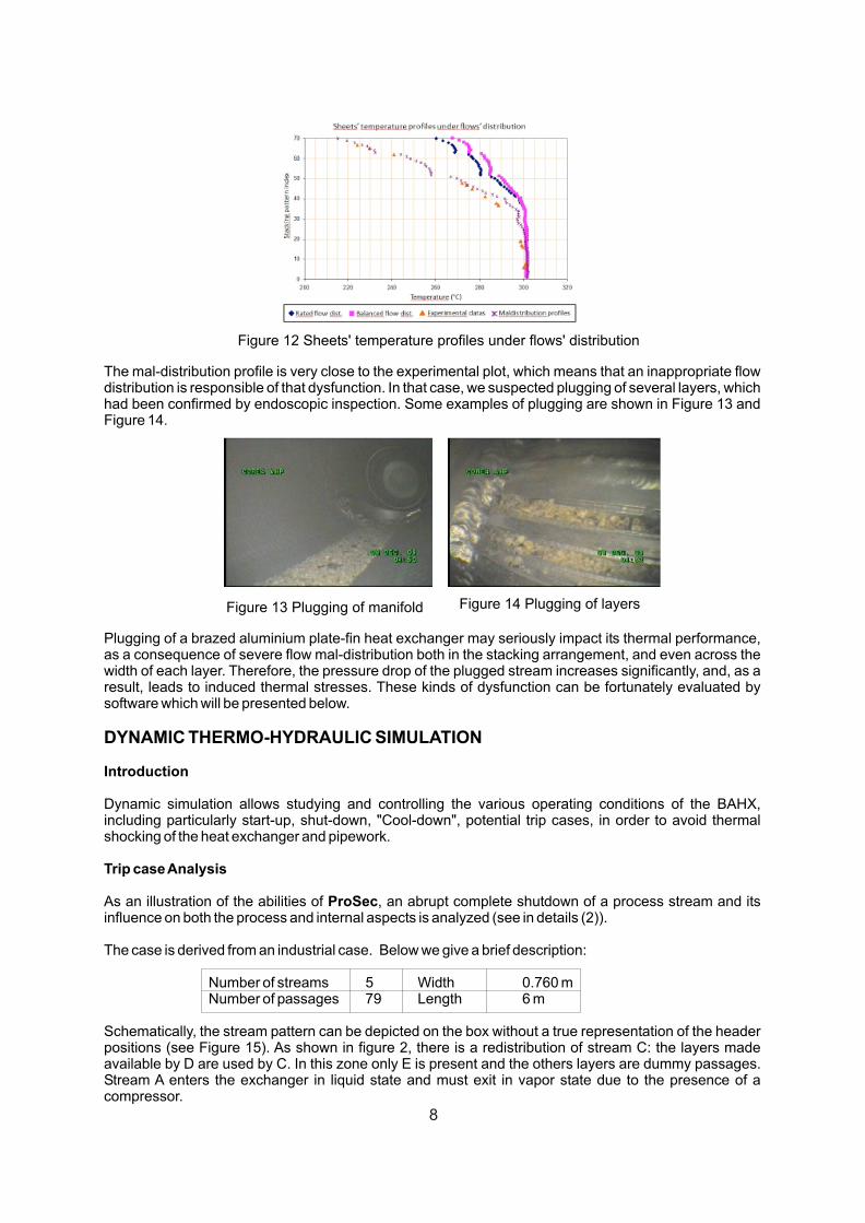
Figure 12 Sheets' temperature profiles under flows' distribution
The mal-distribution profile is very close to the experimental plot, which means that an inappropriate flow distribution is responsible of that dysfunction. In that case, we suspected plugging of several layers, which had been confirmed by endoscopic inspection. Some examples of plugging are shown in Figure 13 and Figure 14.
Plugging of a brazed aluminium plate-fin heat exchanger may seriously impact its thermal performance, as a consequence of severe flow mal-distribution both in the stacking arrangement, and even across the width of each layer. Therefore, the pressure drop of the plugged stream increases significantly, and, as a result, leads to induced thermal stresses. These kinds of dysfunction can be fortunately evaluated by software which will be presented below.
DYNAMIC THERMO-HYDRAULIC SIMULATION
Introduction
Dynamic simulation allows studying and controlling the various operating conditions of the BAHX, including particularly start-up, shut-down, "Cool-down", potential trip cases, in order to avoid thermal shocking of the heat exchanger and pipework.
Trip case Analysis
As an illustration of the abilities of ProSec, an abrupt complete shutdown of a process stream and its influence on both the process and internal aspects is analyzed (see in details (2)).
The case is derived from an industrial case. Below we give a brief description:
Number of streams 5 Width 0.760 mNumber of passages 79 Length 6 m
Schematically, the stream pattern can be depicted on the box without a true representation of the header positions (see Figure 15). As shown in figure 2, there is a redistribution of stream C: the layers made available by D are used by C. In this zone only E is present and the others layers are dummy passages. Stream A enters the exchanger in liquid state and must exit in vapor state due to the presence of a compressor.
Figure 13 Plugging of manifold Figure 14 Plugging of layers
8
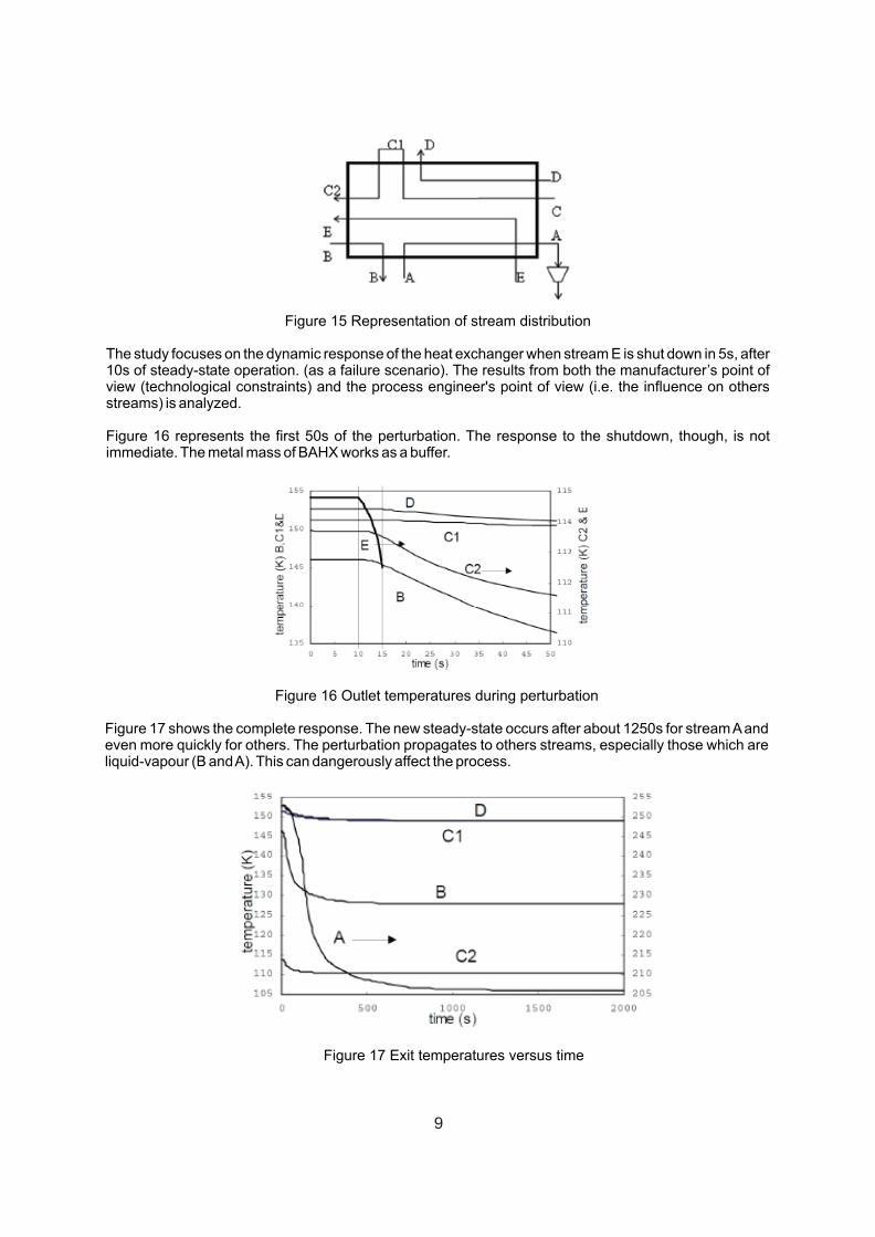
Figure 15 Representation of stream distribution
The study focuses on the dynamic response of the heat exchanger when stream E is shut down in 5s, after 10s of steady-state operation. (as a failure scenario). The results from both the manufacturer’s point of view (technological constraints) and the process engineer's point of view (i.e. the influence on others streams) is analyzed.
Figure 16 represents the first 50s of the perturbation. The response to the shutdown, though, is not immediate. The metal mass of BAHX works as a buffer.
Figure 16 Outlet temperatures during perturbation
Figure 17 shows the complete response. The new steady-state occurs after about 1250s for stream A and even more quickly for others. The perturbation propagates to others streams, especially those which are liquid-vapour (B and A). This can dangerously affect the process.
Figure 17 Exit temperatures versus time
9
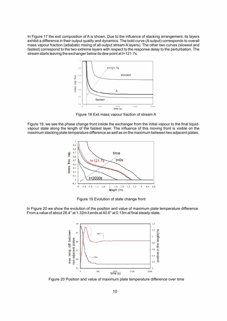
In Figure 17 the exit composition of A is shown. Due to the influence of stacking arrangement, its layers exhibit a difference in their output quality and dynamics. The bold curve (A output) corresponds to overall mass vapour fraction (adiabatic mixing of all output stream A layers). The other two curves (slowest and fastest) correspond to the two extreme layers with respect to the response delay to the perturbation. The stream starts leaving the exchanger below its dew point at t=121.7s.
Figure 18 Exit mass vapour fraction of stream A
Figure 19, we see the phase change front inside the exchanger from the initial vapour to the final liquid-vapour state along the length of the fastest layer. The influence of this moving front is visible on the maximum stacking plate temperature difference as well as on the maximum between two adjacent plates.
Figure 19 Evolution of state change front
In Figure 20 we show the evolution of the position and value of maximum plate temperature difference. From a value of about 28.4° at 1.32m it ends at 40.6° at 0.13m at final steady-state.
Figure 20 Position and value of maximum plate temperature difference over time
10
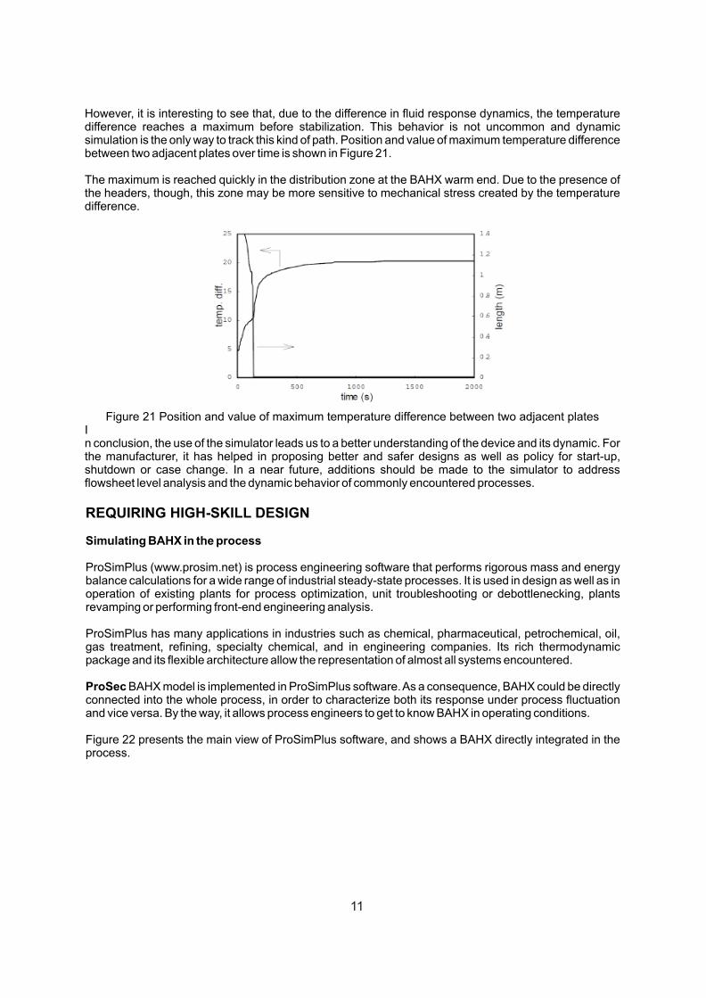
However, it is interesting to see that, due to the difference in fluid response dynamics, the temperature difference reaches a maximum before stabilization. This behavior is not uncommon and dynamic simulation is the only way to track this kind of path. Position and value of maximum temperature difference between two adjacent plates over time is shown in Figure 21.
The maximum is reached quickly in the distribution zone at the BAHX warm end. Due to the presence of the headers, though, this zone may be more sensitive to mechanical stress created by the temperature difference.
Figure 21 Position and value of maximum temperature difference between two adjacent platesIn conclusion, the use of the simulator leads us to a better understanding of the device and its dynamic. For the manufacturer, it has helped in proposing better and safer designs as well as policy for start-up, shutdown or case change. In a near future, additions should be made to the simulator to address flowsheet level analysis and the dynamic behavior of commonly encountered processes.
REQUIRING HIGH-SKILL DESIGN
Simulating BAHX in the process
ProSimPlus (www.prosim.net) is process engineering software that performs rigorous mass and energy balance calculations for a wide range of industrial steady-state processes. It is used in design as well as in operation of existing plants for process optimization, unit troubleshooting or debottlenecking, plants revamping or performing front-end engineering analysis.
ProSimPlus has many applications in industries such as chemical, pharmaceutical, petrochemical, oil, gas treatment, refining, specialty chemical, and in engineering companies. Its rich thermodynamic package and its flexible architecture allow the representation of almost all systems encountered.
ProSec BAHX model is implemented in ProSimPlus software. As a consequence, BAHX could be directly connected into the whole process, in order to characterize both its response under process fluctuation and vice versa. By the way, it allows process engineers to get to know BAHX in operating conditions.
Figure 22 presents the main view of ProSimPlus software, and shows a BAHX directly integrated in the process.
11
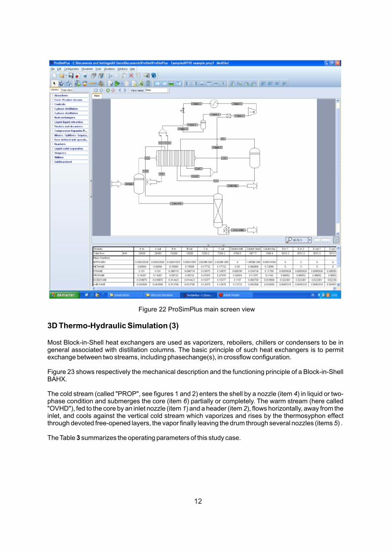
Figure 22 ProSimPlus main screen view
3D Thermo-Hydraulic Simulation (3)
Most Block-in-Shell heat exchangers are used as vaporizers, reboilers, chillers or condensers to be in general associated with distillation columns. The basic principle of such heat exchangers is to permit exchange between two streams, including phasechange(s), in crossflow configuration.
Figure 23 shows respectively the mechanical description and the functioning principle of a Block-in-Shell BAHX.
The cold stream (called "PROP", see figures 1 and 2) enters the shell by a nozzle (item 4) in liquid or two-phase condition and submerges the core (item 6) partially or completely. The warm stream (here called "OVHD"), fed to the core by an inlet nozzle (item 1) and a header (item 2), flows horizontally, away from the inlet, and cools against the vertical cold stream which vaporizes and rises by the thermosyphon effect through devoted free-opened layers, the vapor finally leaving the drum through several nozzles (items 5) .
The Table 3 summarizes the operating parameters of this study case.
12
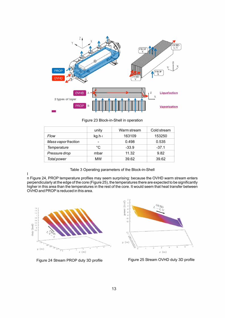
Figure 23 Block-in-Shell in operation
unity Warm stream Cold stream
Flow kg.h-1 163109 153250
Mass vapor fraction - 0.498 0.535
Temperature °C -33.9 -37.1
Pressure drop mbar 11.32 9.82
Total power MW 39.62 39.62
Table 3 Operating parameters of the Block-in-ShellIn Figure 24, PROP temperature profiles may seem surprising: because the OVHD warm stream enters perpendicularly at the edge of the core (Figure 25), the temperatures there are expected to be significantly higher in this area than the temperatures in the rest of the core. It would seem that heat transfer between OVHD and PROP is reduced in this area.
Figure 24 Stream PROP duty 3D profile Figure 25 Stream OVHD duty 3D profile
13
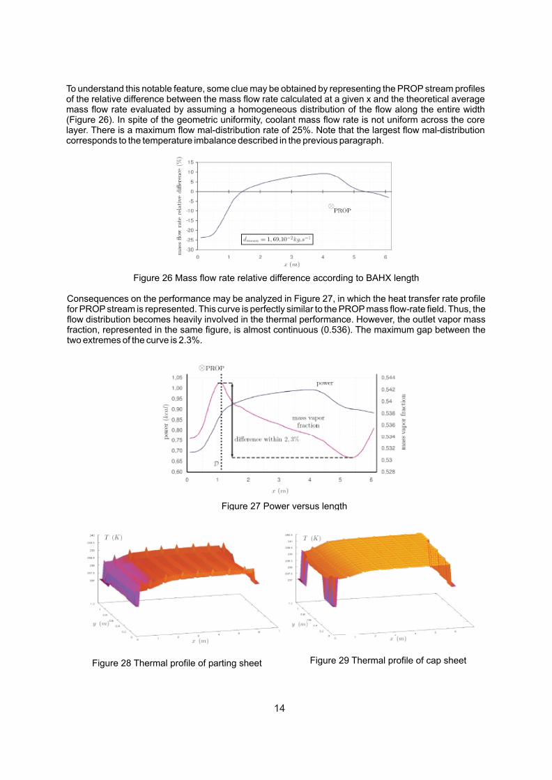
To understand this notable feature, some clue may be obtained by representing the PROP stream profiles of the relative difference between the mass flow rate calculated at a given x and the theoretical average mass flow rate evaluated by assuming a homogeneous distribution of the flow along the entire width (Figure 26). In spite of the geometric uniformity, coolant mass flow rate is not uniform across the core layer. There is a maximum flow mal-distribution rate of 25%. Note that the largest flow mal-distribution corresponds to the temperature imbalance described in the previous paragraph.
Figure 26 Mass flow rate relative difference according to BAHX length
Consequences on the performance may be analyzed in Figure 27, in which the heat transfer rate profile for PROP stream is represented. This curve is perfectly similar to the PROP mass flow-rate field. Thus, the flow distribution becomes heavily involved in the thermal performance. However, the outlet vapor mass fraction, represented in the same figure, is almost continuous (0.536). The maximum gap between the two extremes of the curve is 2.3%.
Figure 27 Power versus length
Figure 28 Thermal profile of parting sheet Figure 29 Thermal profile of cap sheet
14
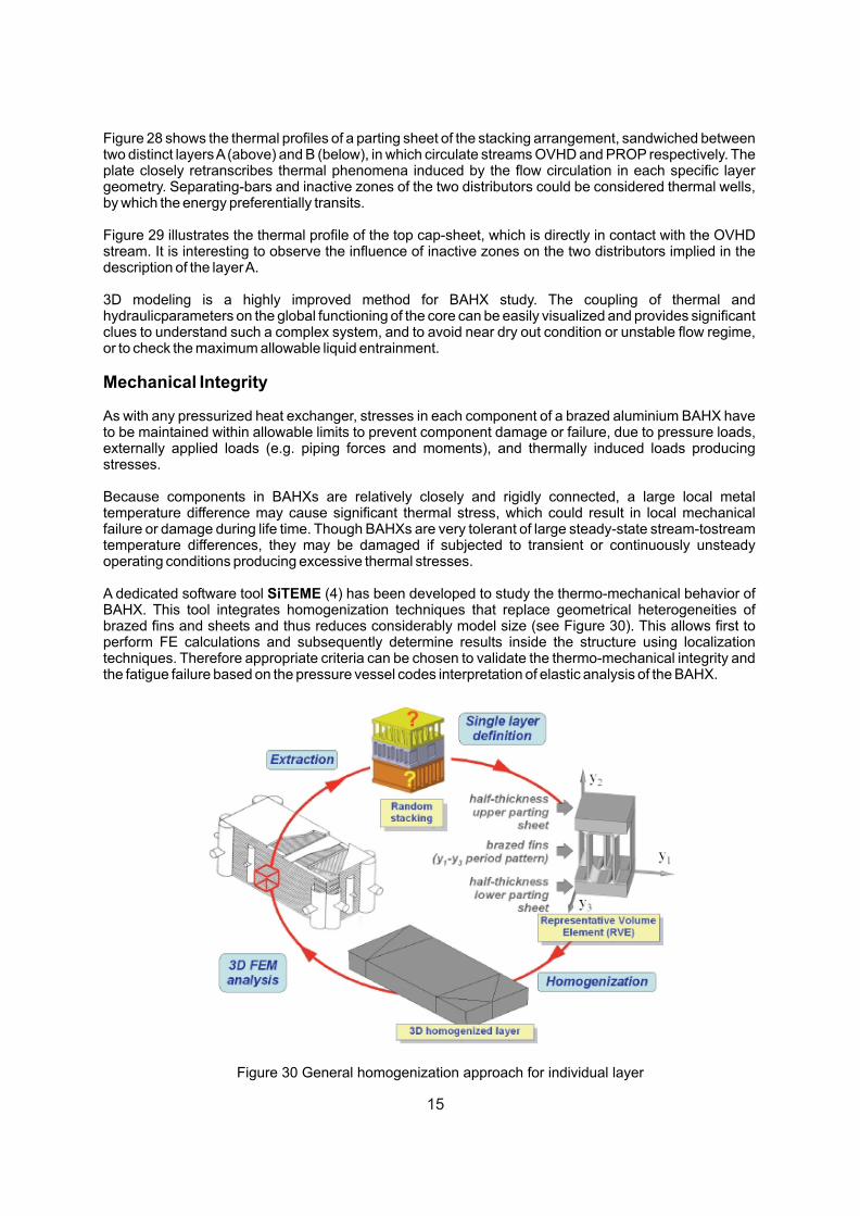
Figure 28 shows the thermal profiles of a parting sheet of the stacking arrangement, sandwiched between two distinct layers A (above) and B (below), in which circulate streams OVHD and PROP respectively. The plate closely retranscribes thermal phenomena induced by the flow circulation in each specific layer geometry. Separating-bars and inactive zones of the two distributors could be considered thermal wells, by which the energy preferentially transits.
Figure 29 illustrates the thermal profile of the top cap-sheet, which is directly in contact with the OVHD stream. It is interesting to observe the influence of inactive zones on the two distributors implied in the description of the layer A.
3D modeling is a highly improved method for BAHX study. The coupling of thermal and hydraulicparameters on the global functioning of the core can be easily visualized and provides significant clues to understand such a complex system, and to avoid near dry out condition or unstable flow regime, or to check the maximum allowable liquid entrainment.
Mechanical Integrity
As with any pressurized heat exchanger, stresses in each component of a brazed aluminium BAHX have to be maintained within allowable limits to prevent component damage or failure, due to pressure loads, externally applied loads (e.g. piping forces and moments), and thermally induced loads producing stresses.
Because components in BAHXs are relatively closely and rigidly connected, a large local metal temperature difference may cause significant thermal stress, which could result in local mechanical failure or damage during life time. Though BAHXs are very tolerant of large steady-state stream-tostream temperature differences, they may be damaged if subjected to transient or continuously unsteady operating conditions producing excessive thermal stresses.
A dedicated software tool SiTEME (4) has been developed to study the thermo-mechanical behavior of BAHX. This tool integrates homogenization techniques that replace geometrical heterogeneities of brazed fins and sheets and thus reduces considerably model size (see Figure 30). This allows first to perform FE calculations and subsequently determine results inside the structure using localization techniques. Therefore appropriate criteria can be chosen to validate the thermo-mechanical integrity and the fatigue failure based on the pressure vessel codes interpretation of elastic analysis of the BAHX.
Figure 30 General homogenization approach for individual layer
15
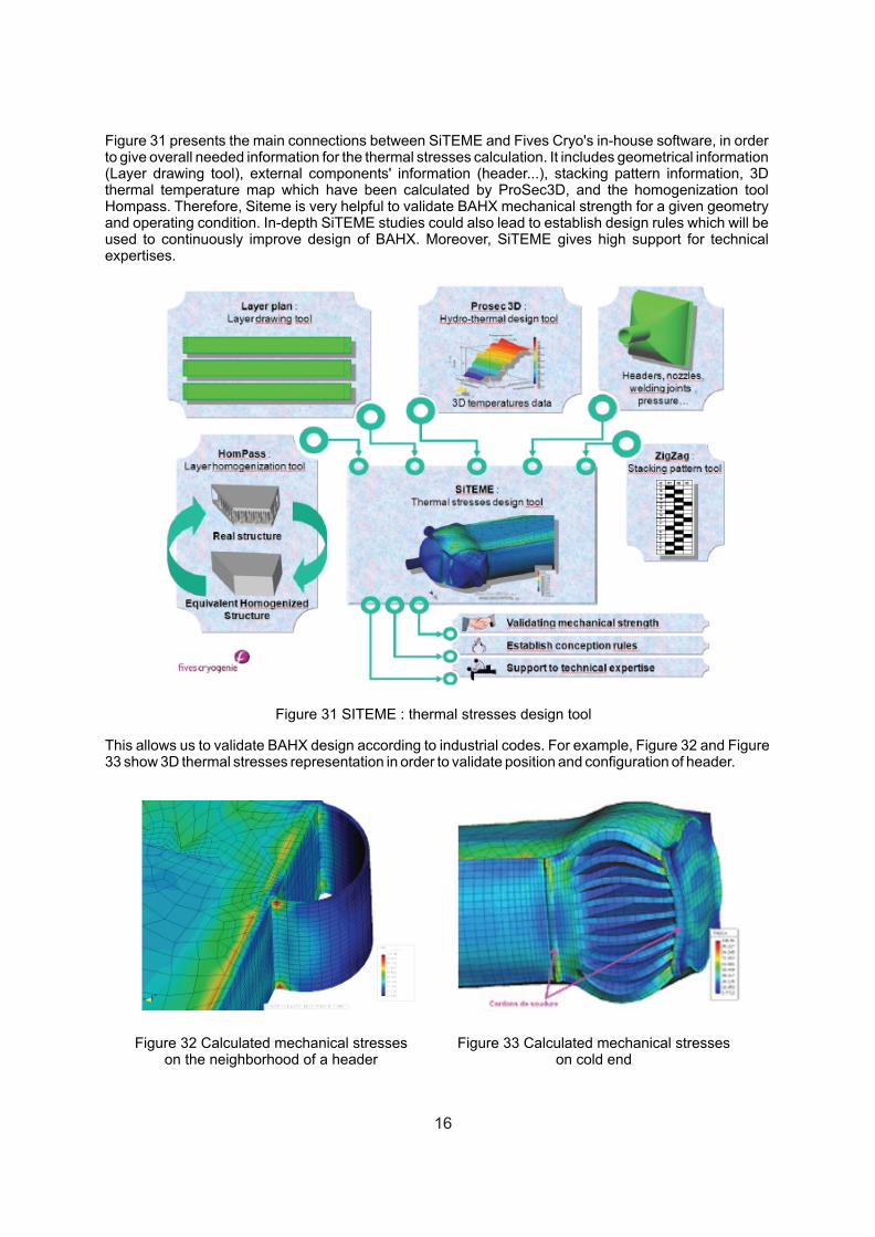
Figure 31 presents the main connections between SiTEME and Fives Cryo's in-house software, in order to give overall needed information for the thermal stresses calculation. It includes geometrical information (Layer drawing tool), external components' information (header...), stacking pattern information, 3D thermal temperature map which have been calculated by ProSec3D, and the homogenization tool Hompass. Therefore, Siteme is very helpful to validate BAHX mechanical strength for a given geometry and operating condition. In-depth SiTEME studies could also lead to establish design rules which will be used to continuously improve design of BAHX. Moreover, SiTEME gives high support for technical expertises.
Figure 31 SITEME : thermal stresses design tool
This allows us to validate BAHX design according to industrial codes. For example, Figure 32 and Figure 33 show 3D thermal stresses representation in order to validate position and configuration of header.
Figure 32 Calculated mechanical stresses on the neighborhood of a header
Figure 33 Calculated mechanical stresses on cold end
16
SUMMARY AND CONCLUSION
Brazed Aluminium Plate-Fin Heat Exchangers are the most compact and energy efficient heat exchangers for handling a wide range of services, noted particularly for their relative high thermal efficiency, compactness, low weight and low maintenance. They provide low capital, installation and operating costs over a wide range of cryogenic and non-cryogenic applications.
But these high-performance heat exchangers need highly skilled design in return, in order to ensure thermal and hydraulic performances and guarantee mechanical strength. Even if the number of exchanger repaired per years is very small, the failure rate still needs to be further reduced.
ProSec allows thermal-hydraulic simulation in order to evaluate the impact on the geometry of the BAHX, including both geometrical parameters (layer stacking arrangement, layer configurations...) And the operating conditions (flow distribution, thermodynamic, mass flow rate, input temperature...), including flow mal-distribution. This allows Fives Cryo the reliability and availability of BAHX.
Moreover, the use of dynamic simulator ProSec brings a better understanding of the device and its behavior versus time. For Fives Cryo, it helps proposing better and safer designs as well as guidelines and recommendations for start-up, shutdown or operating case change.
3D thermal-hydraulic simulations open a new way by including the whole complex configurations used to design BAHX (cross-flow configuration, all kind of distributors...). It allows, in particular, to couple thermal and hydraulic mechanisms in the calculation of the BAHX, and therefore to observe the influence of each parameter (about structure or flow distribution) during operation.
Finally, the possibility to predict the mechanical strength of a BAHX thanks to dedicated in-house software SiTEME, developed to calculate 3D stresses according to given geometry and operating conditions, is described.
REFERENCES
1. ALPEMA. The standards of the Brazed Aluminium Plate-Fin Heat Exchanger Manufacturers' Association. second edition. 2000. www.alpema.org.
2. Dynamic Simulation of Brazed Plate Fin Heat Exchanger. David Averous, Khaled Hammadi, Hervé Pingaud, Xavier Joulia and Philippe Guittard. s.l. : Computers and Chemical Engineering Supplement , 1999.
3. ProSec : Modelling and Simulation in 3D of Brazed Aluminium Plate-Fin Heat Exchangers Core-in- Drum. Florian Picard, David Averous, Xavier Joulia, Denis Barreteau. [ed.] Elsevier. Salvador : s.n., 2009. 10th International Symposium on Process Systems Engineering - PSE2009.
4. Thermo-Mechanical Design of Brazed Plate-Fins Heat Exchanger Based On Finite Element Modeling Using Homogenization Techniques. Johan Dib, Ivan Lewon, Boris Martin (Fives Cryo). Prague, Czech Republic : s.n., July 26-30, 2009,. 2009 ASME Pressure Vessels and Piping Division Conference. PVP2009-77251.
17