heat 4e sm chap07
TRANSCRIPT
PROPRIETARY MATERIAL. © 2011 The McGraw-Hill Companies, Inc. Limited distribution permitted only to teachers and educators for course preparation. If you are a student using this Manual, you are using it without permission.
7-1
Solutions Manual for
Heat and Mass Transfer: Fundamentals & Applications Fourth Edition
Yunus A. Cengel & Afshin J. Ghajar McGraw-Hill, 2011
Chapter 7 EXTERNAL FORCED CONVECTION
PROPRIETARY AND CONFIDENTIAL This Manual is the proprietary property of The McGraw-Hill Companies, Inc. (“McGraw-Hill”) and protected by copyright and other state and federal laws. By opening and using this Manual the user agrees to the following restrictions, and if the recipient does not agree to these restrictions, the Manual should be promptly returned unopened to McGraw-Hill: This Manual is being provided only to authorized professors and instructors for use in preparing for the classes using the affiliated textbook. No other use or distribution of this Manual is permitted. This Manual may not be sold and may not be distributed to or used by any student or other third party. No part of this Manual may be reproduced, displayed or distributed in any form or by any means, electronic or otherwise, without the prior written permission of McGraw-Hill.
PROPRIETARY MATERIAL. © 2011 The McGraw-Hill Companies, Inc. Limited distribution permitted only to teachers and educators for course preparation. If you are a student using this Manual, you are using it without permission.
7-2
Drag Force and Heat Transfer in External Flow
7-1C The part of drag that is due directly to wall shear stress τw is called the skin friction drag FD, friction since it is caused by frictional effects, and the part that is due directly to pressure P and depends strongly on the shape of the body is called the pressure drag FD, pressure. For slender bodies such as airfoils, the friction drag is usually more significant.
7-2C A body is said to be streamlined if a conscious effort is made to align its shape with the anticipated streamlines in the flow. Otherwise, a body tends to block the flow, and is said to be blunt. A tennis ball is a blunt body (unless the velocity is very low and we have “creeping flow”).
7-3C The force a flowing fluid exerts on a body in the flow direction is called drag. Drag is caused by friction between the fluid and the solid surface, and the pressure difference between the front and back of the body. We try to minimize drag in order to reduce fuel consumption in vehicles, improve safety and durability of structures subjected to high winds, and to reduce noise and vibration.
7-4C The force a flowing fluid exerts on a body in the normal direction to flow that tend to move the body in that direction is called lift. It is caused by the components of the pressure and wall shear forces in the normal direction to flow. The wall shear also contributes to lift (unless the body is very slim), but its contribution is usually small.
7-5C When the drag force FD, the upstream velocity V, and the fluid density ρ are measured during flow over a body, the drag coefficient can be determined from
AVF
C DD 2
21 ρ
=
where A is ordinarily the frontal area (the area projected on a plane normal to the direction of flow) of the body.
7-6C The frontal area of a body is the area seen by a person when looking from upstream. The frontal area is appropriate to use in drag and lift calculations for blunt bodies such as cars, cylinders, and spheres.
7-7C The velocity of the fluid relative to the immersed solid body sufficiently far away from a body is called the free-stream velocity, V∞. The upstream (or approach) velocity V is the velocity of the approaching fluid far ahead of the body. These two velocities are equal if the flow is uniform and the body is small relative to the scale of the free-stream flow.
7-8C At sufficiently high velocities, the fluid stream detaches itself from the surface of the body. This is called separation. It is caused by a fluid flowing over a curved surface at a high velocity (or technically, by adverse pressure gradient). Separation increases the drag coefficient drastically.
PROPRIETARY MATERIAL. © 2011 The McGraw-Hill Companies, Inc. Limited distribution permitted only to teachers and educators for course preparation. If you are a student using this Manual, you are using it without permission.
7-3
7-9C As a result of streamlining, (a) friction drag increases, (b) pressure drag decreases, and (c) total drag decreases at high Reynolds numbers (the general case), but increases at very low Reynolds numbers since the friction drag dominates at low Reynolds numbers.
7-10C The friction drag coefficient is independent of surface roughness in laminar flow, but is a strong function of surface roughness in turbulent flow due to surface roughness elements protruding further into the highly viscous laminar sublayer.
PROPRIETARY MATERIAL. © 2011 The McGraw-Hill Companies, Inc. Limited distribution permitted only to teachers and educators for course preparation. If you are a student using this Manual, you are using it without permission.
7-4
Flow over Flat Plates
7-11C The friction and the heat transfer coefficients change with position in laminar flow over a flat plate.
7-12C The friction coefficient represents the resistance to fluid flow over a flat plate. It is proportional to the drag force acting on the plate. The drag coefficient for a flat surface is equivalent to the mean friction coefficient.
7-13C The average friction and heat transfer coefficients in flow over a flat plate are determined by integrating the local friction and heat transfer coefficients over the entire plate, and then dividing them by the length of the plate.
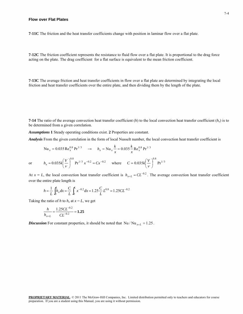
7-14 The ratio of the average convection heat transfer coefficient (h) to the local convection heat transfer coefficient (hx) is to be determined from a given correlation.
Assumptions 1 Steady operating conditions exist. 2 Properties are constant.
Analysis From the given correlation in the form of local Nusselt number, the local convection heat transfer coefficient is
→ 3/18.0 PrRe035.0Nu xx = 3/18.0 PrRe035.0Nu xxx xk
xkh ==
or 2.02.03/18.0
Pr035.0 −− =⎟⎠⎞
⎜⎝⎛= CxxVkhx ν
where 3/18.0
Pr035.0 ⎟⎠⎞
⎜⎝⎛=νVkC
At x = L, the local convection heat transfer coefficient is . The average convection heat transfer coefficient over the entire plate length is
2.0−= = CLh Lx
2.08.0
0
2.0
025.125.11 −− ==== ∫∫ CLL
LCdxx
LCdxh
Lh
LLx
Taking the ratio of h to hx at x = L, we get
1.25==−
−
=2.0
2.025.1CL
CLh
h
Lx
Discussion For constant properties, it should be noted that 25.1Nu/Nu ==Lx .
PROPRIETARY MATERIAL. © 2011 The McGraw-Hill Companies, Inc. Limited distribution permitted only to teachers and educators for course preparation. If you are a student using this Manual, you are using it without permission.
7-5
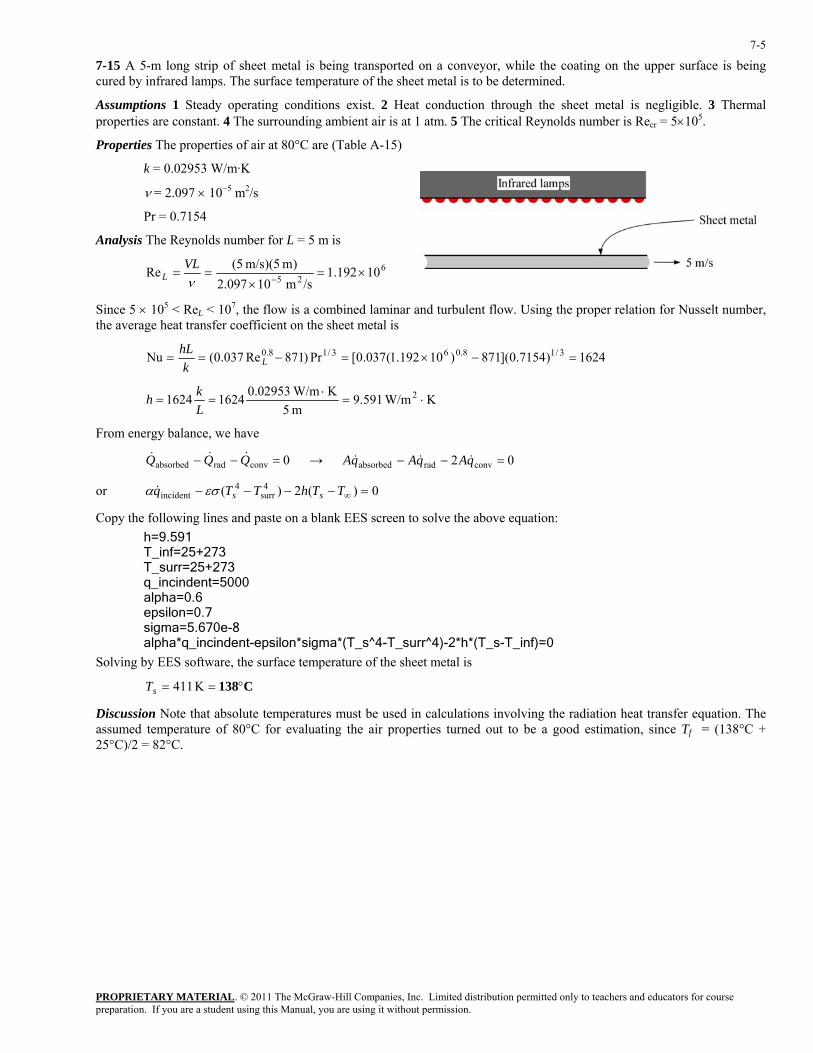
7-15 A 5-m long strip of sheet metal is being transported on a conveyor, while the coating on the upper surface is being cured by infrared lamps. The surface temperature of the sheet metal is to be determined.
Assumptions 1 Steady operating conditions exist. 2 Heat conduction through the sheet metal is negligible. 3 Thermal properties are constant. 4 The surrounding ambient air is at 1 atm. 5 The critical Reynolds number is Recr = 5×10⁵.
Properties The properties of air at 80°C are (Table A-15)
k = 0.02953 W/m·K
ν = 2.097 × 10⁻⁵ m2/s
Pr = 0.7154
Analysis The Reynolds number for L = 5 m is
625 10192.1/sm 10097.2
)m 5)(m/s 5(Re ×=×
==−ν
VLL
Since 5 × 10⁵ < ReL < 107, the flow is a combined laminar and turbulent flow. Using the proper relation for Nusselt number, the average heat transfer coefficient on the sheet metal is
1624)7154.0](871)10192.1(037.0[Pr)871Re037.0(Nu 3/18.063/18.0 =−×=−== LkhL
K W/m591.9m 5
K W/m02953.016241624 2 ⋅=⋅
==Lkh
From energy balance, we have
→ 0convradabsorbed =−− QQQ &&& 02 convradabsorbed =−− qAqAqA &&&
or 0)(2)( 4surr
4incident =−−−− ∞TThTTq ssεσα &
Copy the following lines and paste on a blank EES screen to solve the above equation: h=9.591 T_inf=25+273 T_surr=25+273 q_incindent=5000 alpha=0.6 epsilon=0.7 sigma=5.670e-8 alpha*q_incindent-epsilon*sigma*(T_s^4-T_surr^4)-2*h*(T_s-T_inf)=0
Solving by EES software, the surface temperature of the sheet metal is
C138°== K 411sT
Discussion Note that absolute temperatures must be used in calculations involving the radiation heat transfer equation. The assumed temperature of 80°C for evaluating the air properties turned out to be a good estimation, since Tf = (138°C + 25°C)/2 = 82°C.
PROPRIETARY MATERIAL. © 2011 The McGraw-Hill Companies, Inc. Limited distribution permitted only to teachers and educators for course preparation. If you are a student using this Manual, you are using it without permission.
7-6
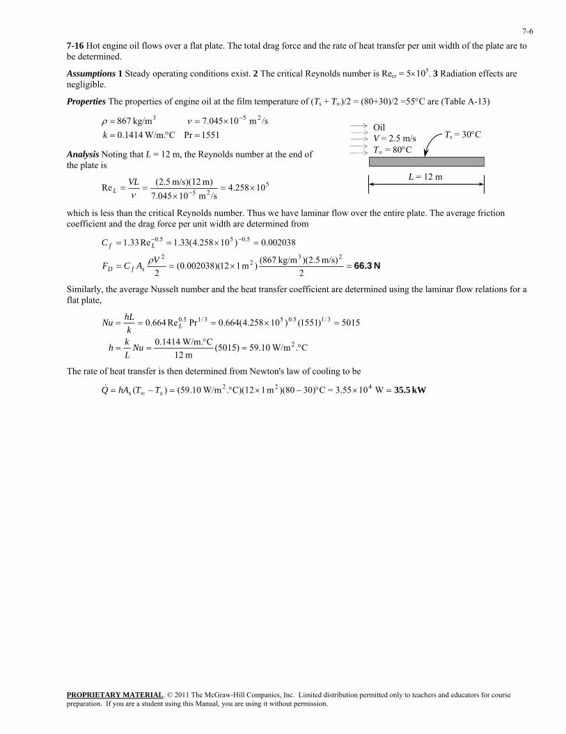
7-16 Hot engine oil flows over a flat plate. The total drag force and the rate of heat transfer per unit width of the plate are to be determined.
Assumptions 1 Steady operating conditions exist. 2 The critical Reynolds number is Recr = 5×10⁵. 3 Radiation effects are negligible.
Properties The properties of engine oil at the film temperature of (Ts + T∞)/2 = (80+30)/2 =55°C are (Table A-13)
1551PrC W/m.1414.0
/sm 10045.7kg/m 867 253
=°=×== −
kνρ
Ts = 30°C Oil V = 2.5 m/s T∞ = 80°C
L = 12 m
Analysis Noting that L = 12 m, the Reynolds number at the end of the plate is
525 10258.4/sm 10045.7
m) m/s)(12 5.2(Re ×=×
==−ν
VLL
which is less than the critical Reynolds number. Thus we have laminar flow over the entire plate. The average friction coefficient and the drag force per unit width are determined from
N 66.3=×==
=×== −−
2m/s) )(2.5kg/m 867()m 112)(002038.0(
2
002038.0)10258.4(33.1Re33.123
22
5.055.0
VACF
C
sfD
Lf
ρ
Similarly, the average Nusselt number and the heat transfer coefficient are determined using the laminar flow relations for a flat plate,
C. W/m10.59)5015(
m 12C W/m.1414.0
5015)1551()10258.4(664.0PrRe664.0
2
3/15.053/15.0
°=°
==
=×===
NuLkh
khLNu L
The rate of heat transfer is then determined from Newton's law of cooling to be
kW 35.5=×°−×°=−= ∞ W103.55=C30))(80m 1C)(12. W/m10.59()( 422ss TThAQ&
PROPRIETARY MATERIAL. © 2011 The McGraw-Hill Companies, Inc. Limited distribution permitted only to teachers and educators for course preparation. If you are a student using this Manual, you are using it without permission.
7-7
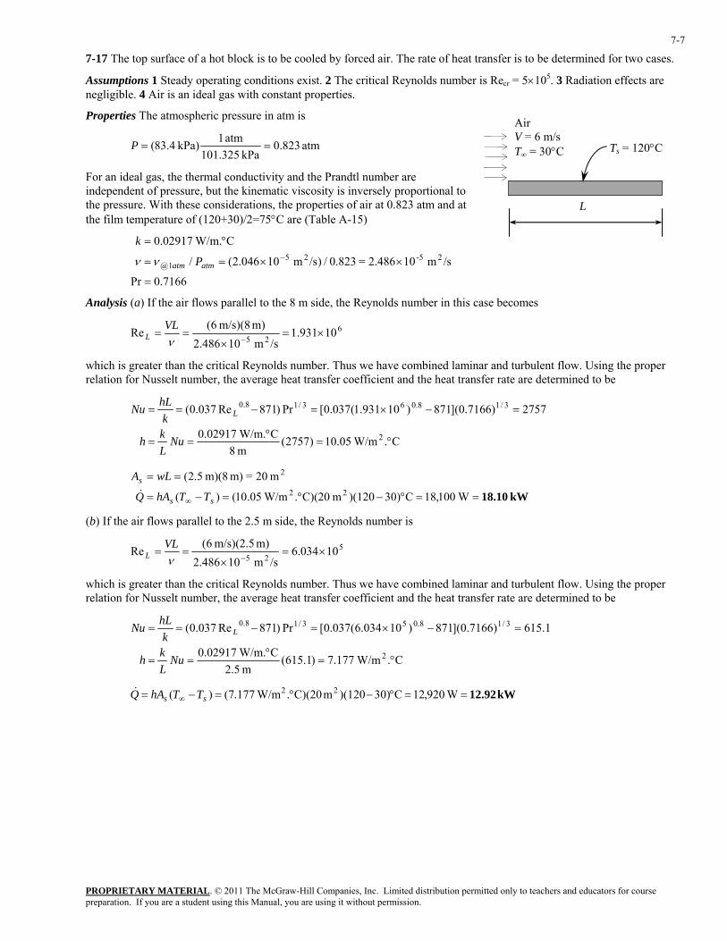
7-17 The top surface of a hot block is to be cooled by forced air. The rate of heat transfer is to be determined for two cases.
Assumptions 1 Steady operating conditions exist. 2 The critical Reynolds number is Recr = 5×10⁵. 3 Radiation effects are negligible. 4 Air is an ideal gas with constant properties.
Properties The atmospheric pressure in atm is
Ts = 120°C
Air V = 6 m/s T∞ = 30°C atm 823.0
kPa 101.325atm 1kPa) 4.83( ==P
For an ideal gas, the thermal conductivity and the Prandtl number are independent of pressure, but the kinematic viscosity is inversely proportional to the pressure. With these considerations, the properties of air at 0.823 atm and at the film temperature of (120+30)/2=75°C are (Table A-15)
L
7166.0Pr
/sm 102.486=823.0/)/sm 10046.2(/
C W/m.02917.025-25
1@
=
××==
°=−
atmatm P
k
νν
Analysis (a) If the air flows parallel to the 8 m side, the Reynolds number in this case becomes
625
10931.1/sm 10486.2
m) m/s)(8 6(Re ×=
×==
−νVL
L
which is greater than the critical Reynolds number. Thus we have combined laminar and turbulent flow. Using the proper relation for Nusselt number, the average heat transfer coefficient and the heat transfer rate are determined to be
C. W/m05.10)2757(
m 8C W/m.02917.0
2757)7166.0](871)10931.1(037.0[Pr)871Re037.0(
2
3/18.063/18.0
°=°
==
=−×=−==
NuLkh
khLNu L
kW 18.10==°−°=−=
==
∞ W100,18C30))(120m C)(20. W/m05.10()(
m 20=m) m)(8 2.5(22
2
ss
s
TThAQ
wLA&
(b) If the air flows parallel to the 2.5 m side, the Reynolds number is
525
10034.6/sm 10486.2
m) m/s)(2.5 6(Re ×=
×==
−νVL
L
which is greater than the critical Reynolds number. Thus we have combined laminar and turbulent flow. Using the proper relation for Nusselt number, the average heat transfer coefficient and the heat transfer rate are determined to be
C. W/m177.7)1.615(
m 5.2C W/m.02917.0
1.615)7166.0](871)10034.6(037.0[Pr)871Re037.0(
2
3/18.053/18.0
°=°
==
=−×=−==
NuLkh
khLNu L
kW 12.92==°−°=−= ∞ W920,12C30))(120m C)(20. W/m177.7()( 22ss TThAQ&
PROPRIETARY MATERIAL. © 2011 The McGraw-Hill Companies, Inc. Limited distribution permitted only to teachers and educators for course preparation. If you are a student using this Manual, you are using it without permission.
7-8
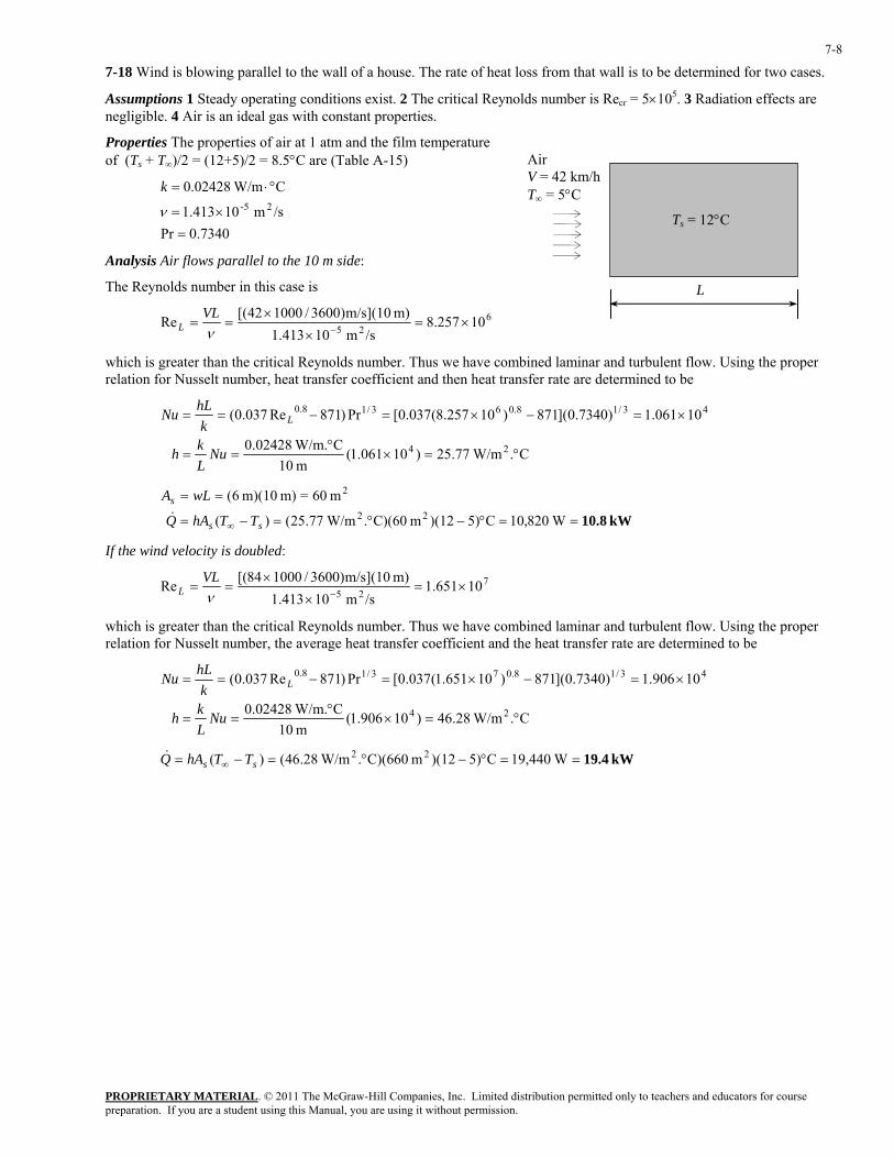
7-18 Wind is blowing parallel to the wall of a house. The rate of heat loss from that wall is to be determined for two cases.
Assumptions 1 Steady operating conditions exist. 2 The critical Reynolds number is Recr = 5×10⁵. 3 Radiation effects are negligible. 4 Air is an ideal gas with constant properties.
Properties The properties of air at 1 atm and the film temperature of (Ts + T∞)/2 = (12+5)/2 = 8.5°C are (Table A-15)
Ts = 12°C
Air V = 42 km/h T∞ = 5°C
7340.0Pr
/sm 10413.1
C W/m02428.025-
=×=
°⋅=
ν
k
Analysis Air flows parallel to the 10 m side:
The Reynolds number in this case is L
625 10257.8/sm 10413.1
m) m/s](10)3600/100042[(Re ×=×
×==
−νVL
L
which is greater than the critical Reynolds number. Thus we have combined laminar and turbulent flow. Using the proper relation for Nusselt number, heat transfer coefficient and then heat transfer rate are determined to be
C. W/m77.25)10061.1(
m 10C W/m.02428.0
10061.1)7340.0](871)10257.8(037.0[Pr)871Re037.0(
24
43/18.063/18.0
°=×°
==
×=−×=−==
NuLkh
khLNu L
kW 10.8==°−°=−=
==
∞ W820,10C5))(12m C)(60. W/m77.25()(
m 60=m) m)(10 6(22
2
ss
s
TThAQ
wLA&
If the wind velocity is doubled:
725 10651.1/sm 10413.1
m) m/s](10)3600/100084[(Re ×=×
×==
−νVL
L
which is greater than the critical Reynolds number. Thus we have combined laminar and turbulent flow. Using the proper relation for Nusselt number, the average heat transfer coefficient and the heat transfer rate are determined to be
C. W/m28.46)10906.1(
m 10C W/m.02428.0
10906.1)7340.0](871)10651.1(037.0[Pr)871Re037.0(
24
43/18.073/18.0
°=×°
==
×=−×=−==
NuLkh
khLNu L
kW 19.4==°−°=−= ∞ W440,19C5))(12m C)(660. W/m28.46()( 22ss TThAQ&
PROPRIETARY MATERIAL. © 2011 The McGraw-Hill Companies, Inc. Limited distribution permitted only to teachers and educators for course preparation. If you are a student using this Manual, you are using it without permission.
7-9
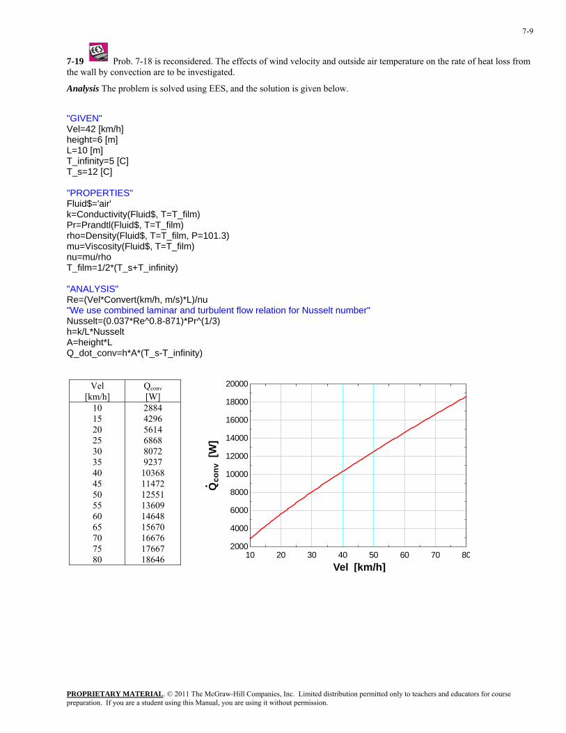
7-19 Prob. 7-18 is reconsidered. The effects of wind velocity and outside air temperature on the rate of heat loss from the wall by convection are to be investigated.
Analysis The problem is solved using EES, and the solution is given below.
"GIVEN" Vel=42 [km/h] height=6 [m] L=10 [m] T_infinity=5 [C] T_s=12 [C] "PROPERTIES" Fluid$='air' k=Conductivity(Fluid$, T=T_film) Pr=Prandtl(Fluid$, T=T_film) rho=Density(Fluid$, T=T_film, P=101.3) mu=Viscosity(Fluid$, T=T_film) nu=mu/rho T_film=1/2*(T_s+T_infinity) "ANALYSIS" Re=(Vel*Convert(km/h, m/s)*L)/nu "We use combined laminar and turbulent flow relation for Nusselt number" Nusselt=(0.037*Re^0.8-871)*Pr^(1/3) h=k/L*Nusselt A=height*L Q_dot_conv=h*A*(T_s-T_infinity)
Vel [km/h]
Qconv [W]
10 15 20 25 30 35 40 45 50 55 60 65 70 75 80
2884 4296 5614 6868 8072 9237
10368 11472 12551 13609 14648 15670 16676 17667 18646 10 20 30 40 50 60 70 80
2000
4000
6000
8000
10000
12000
14000
16000
18000
20000
Vel [km/h]
Qco
nv [
W]
PROPRIETARY MATERIAL. © 2011 The McGraw-Hill Companies, Inc. Limited distribution permitted only to teachers and educators for course preparation. If you are a student using this Manual, you are using it without permission.
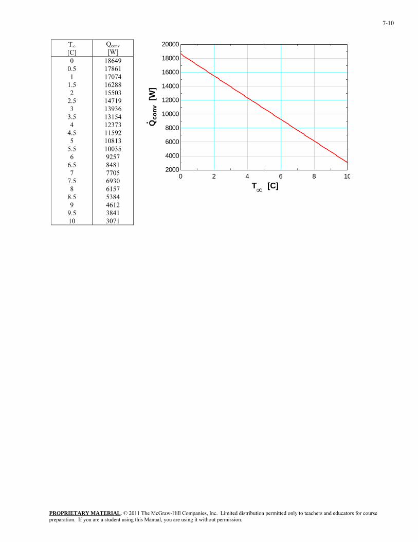
7-10
T∞ [C]
Qconv [W]
0 0.5 1
1.5 2
2.5 3
3.5 4
4.5 5
5.5 6
6.5 7
7.5 8
8.5 9
9.5 10
18649 17861 17074 16288 15503 14719 13936 13154 12373 11592 10813 10035 9257 8481 7705 6930 6157 5384 4612 3841 3071
0 2 4 6 8 102000
4000
6000
8000
10000
12000
14000
16000
18000
20000
T∞ [C]
Qco
nv [
W]
PROPRIETARY MATERIAL. © 2011 The McGraw-Hill Companies, Inc. Limited distribution permitted only to teachers and educators for course preparation. If you are a student using this Manual, you are using it without permission.
7-11
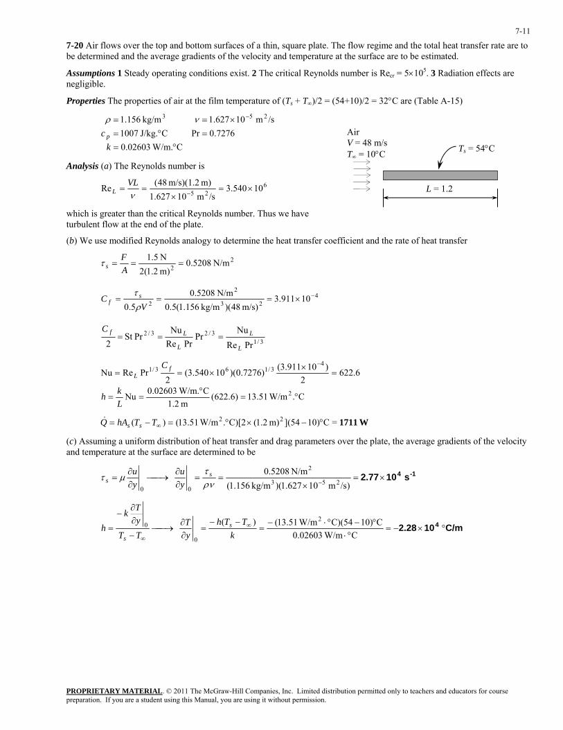
7-20 Air flows over the top and bottom surfaces of a thin, square plate. The flow regime and the total heat transfer rate are to be determined and the average gradients of the velocity and temperature at the surface are to be estimated.
Assumptions 1 Steady operating conditions exist. 2 The critical Reynolds number is Recr = 5×10⁵. 3 Radiation effects are negligible.
Properties The properties of air at the film temperature of (Ts + T∞)/2 = (54+10)/2 = 32°C are (Table A-15)
C W/m.02603.0
7276.0PrCJ/kg. 1007/sm 10627.1kg/m 156.1 253
°==°=
×== −
kc p
νρ
Ts = 54°C
Air V = 48 m/sT∞ = 10°C
L = 1.2
Analysis (a) The Reynolds number is
625 10540.3/sm 10627.1
m) m/s)(1.2 48(Re ×=×
==−ν
VLL
which is greater than the critical Reynolds number. Thus we have turbulent flow at the end of the plate.
(b) We use modified Reynolds analogy to determine the heat transfer coefficient and the rate of heat transfer
22 N/m 5208.0
m) 2.1(2N 5.1
===AF
sτ
423
2
2 10911.3m/s) 48)(kg/m 156.1(5.0
N/m 5208.05.0
−×===V
C sf
ρτ
3/1
3/23/2
PrReNu
PrPrRe
NuPrSt
2 L
L
L
LfC===
6.6222
)10911.3()7276.0)(10540.3(2
PrReNu4
3/163/1 =×
×==−
fL
C
C. W/m51.13)6.622(m 2.1
C W/m.02603.0Nu 2 °=°
==Lkh
W1711=C10)](54m) 2.1(C)[2. W/m51.13()( 22 °−×°=−= ∞TThAQ ss&
(c) Assuming a uniform distribution of heat transfer and drag parameters over the plate, the average gradients of the velocity and temperature at the surface are determined to be
1-4 s 102.77×=×
==∂∂
⎯→⎯∂∂
=− )/sm 10627.1)(kg/m 156.1(
N/m 5208.0 253
2
00 ρντ
µτ ss y
uyu
C/m 102.28 4 °×−=°⋅
°−°⋅−=
−−=
∂∂
⎯→⎯−
∂∂
−
= ∞
∞ C W/m02603.0C10)C)(54 W/m51.13()(
2
0
0
kTTh
yT
TTyTk
h s
s
PROPRIETARY MATERIAL. © 2011 The McGraw-Hill Companies, Inc. Limited distribution permitted only to teachers and educators for course preparation. If you are a student using this Manual, you are using it without permission.
7-12
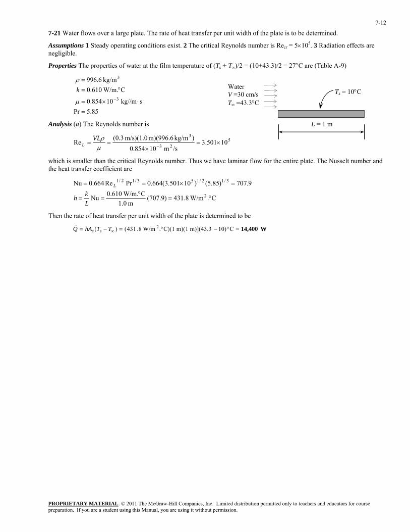
7-21 Water flows over a large plate. The rate of heat transfer per unit width of the plate is to be determined.
Assumptions 1 Steady operating conditions exist. 2 The critical Reynolds number is Recr = 5×10⁵. 3 Radiation effects are negligible.
Properties The properties of water at the film temperature of (Ts + T∞)/2 = (10+43.3)/2 = 27°C are (Table A-9)
85.5Prskg//m 10854.0
C W/m.610.0kg/m 6.996
3
3
=⋅×=
°==
−µ
ρk Water
V =30 cm/sT∞ =43.3°C
Ts = 10°C
L = 1 mAnalysis (a) The Reynolds number is
523
310501.3
/sm 10854.0)kg/m m)(996.6 m/s)(1.0 3.0(Re ×=
×==
−µρVL
L
which is smaller than the critical Reynolds number. Thus we have laminar flow for the entire plate. The Nusselt number and the heat transfer coefficient are
9.707)85.5()10501.3(664.0PrRe664.0Nu 3/12/153/12/1 =×== L
C. W/m8.431)9.707(m 0.1
C W/m.610.0Nu 2 °=°
==Lkh
Then the rate of heat transfer per unit width of the plate is determined to be
W14,400=C10)m)](43.3 m)(1 C)(1. W/m8.431()( 2 °−°=−= ∞TThAQ ss&
PROPRIETARY MATERIAL. © 2011 The McGraw-Hill Companies, Inc. Limited distribution permitted only to teachers and educators for course preparation. If you are a student using this Manual, you are using it without permission.
7-13
7-22E Warm air blowing over the inner surface of an automobile windshield is used for defrosting ice accumulated on the outer surface. The convection heat transfer coefficient for the warm air blowing over the inner surface of the windshield, necessary to cause the accumulated ice to begin melting, is to be determined.
Assumptions 1 Steady operating conditions exist. 2 Heat transfer through the windshield is one-dimensional. 3 Thermal properties are constant. 4 Heat transfer by radiation is negligible. 5 The outside air pressure is 1 atm. 6 The critical Reynolds number is Recr = 5×10⁵.
Properties The properties of air at the film temperature of Tf = (8°F + 32°F)/2 = 20°F are k = 0.01336 Btu/h·ft·R, ν = 1.379 × 10⁻⁴ ft2/s, Pr = 0.7378 (from Table A-15E).
Analysis On the outer surface of the windshield, the Reynolds number at L = 20 in. is
524 10863.8/sft 10379.1
)ft 12/20)(ft/s 46667.150(Re ×=×
×==
−νVL
L
Since 5 × 10⁵ < ReL < 107, the flow is a combined laminar and turbulent flow. Using the proper relation for Nusselt number, the average heat transfer coefficient on the outer surface of the windshield is
1128)7378.0](871)10863.8(037.0[Pr)871Re037.0(Nu 3/18.053/18.0 =−×=−== Lo
o kLh
RftBtu/h 042.9ft 12/20
RftBtu/h 01336.011281128 2 ⋅⋅=⋅⋅
==Lkho
From energy balance, the heat transfer through the windshield thickness can be written as
iw
ios
o
oso
hktTT
hTT
/1//1,,,,
+
−=
− ∞∞
For the ice to begin melting, the outer surface temperature of the windshield ( ) should be at least 32°F. The convection heat transfer coefficient for the warm air blowing over the inner surface of the windshield is
osT ,
RftBtu/h 5.36 2 ⋅⋅=
⎥⎦
⎤⎢⎣
⎡⋅⋅
−⎟⎠
⎞⎜⎝
⎛⋅⋅°−
°−=
⎟⎟⎠
⎞⎜⎜⎝
⎛−
−
−=
−
−
∞
∞
1
2
1
,,
,,
RftBtu/h 8.0ft 12/2.0
RftBtu/h 042.91
F)328(F)7732(
1
woso
ios
oi k
tTTTT
hh
Discussion To keep the ice from accumulating for the given conditions, the convection heat transfer coefficient for the warm air blowing over the inner surface of the windshield needs to be at least 5.36 Btu/h·ft2·R or higher.
PROPRIETARY MATERIAL. © 2011 The McGraw-Hill Companies, Inc. Limited distribution permitted only to teachers and educators for course preparation. If you are a student using this Manual, you are using it without permission.
7-14
7-23 Hot carbon dioxide exhaust gas is being cooled by flat plates, (a) the local convection heat transfer coefficient at 1 m from the leading edge, (b) the average convection heat transfer coefficient over the entire plate, and (c) the total heat flux transfer to the plate are to be determined.
Assumptions 1 Steady operating conditions exist. 2 Surface temperature is uniform throughout the plate. 3 Thermal properties are constant. 4 The critical Reynolds number is Recr = 5×10⁵. 5 Heat transfer by radiation is negligible.
Properties The properties of CO2 at Tf = (220°C + 80°C)/2 = 150°C are k = 0.02652 W/m·K, ν = 1.627 × 10⁻⁵ m2/s, Pr = 0.7445 (from Table A-16).
Analysis (a) The Reynolds number at x = 1 m is
525 10844.1/sm 10627.1
)m 1)(m/s 3(Re ×=×
==−ν
Vxx
Since Rex < 5 × 10⁵, the flow is laminar. Using the proper relation for Nusselt number, the local heat transfer coefficient at 1 m from the leading edge of the flat plate is
2.129)7445.0()10844.1(332.0PrRe332.0Nu 3/15.053/15.0x =×=== x
x
kxh
K W/m3.426 2 ⋅=⋅
==m 1
K W/m02652.02.1292.129xkhx
(b) The Reynolds number at L = 1.5 m is
525 10766.2/sm 10627.1
)m 5.1)(m/s 3(Re ×=×
==−ν
VLL
Since Rex < 5 × 10⁵, the flow is laminar. Using the proper relation for Nusselt number, the average heat transfer coefficient of the entire flat plate is
5.316)7445.0()10766.2(664.0PrRe664.0Nu 3/15.053/15.0 =×=== LkhL
K W/m5.596 2 ⋅=⋅
==m 5.1
K W/m02652.05.3165.316Lkh
(c) The total heat flux transfer to the flat plate on the upper and lower surfaces is
2 W/m1567=−⋅=−= ∞ K )80220)(K W/m596.5(2)(2 2conv sTThq&
Discussion The average convection heat transfer coefficient calculated in part (b) is relatively low, which indicates that the role of natural convection may be important.
PROPRIETARY MATERIAL. © 2011 The McGraw-Hill Companies, Inc. Limited distribution permitted only to teachers and educators for course preparation. If you are a student using this Manual, you are using it without permission.
7-15
7-24 Hot engine oil is flowing in parallel over a flat plate, the local convection heat transfer coefficient at 0.2 m from the leading edge and the average convection heat transfer coefficient over the entire plate are to be determined.
Assumptions 1 Steady operating conditions exist. 2 Surface temperature is uniform throughout the plate. 3 Thermal properties are constant. 4 The critical Reynolds number is Recr = 5×10⁵.
Properties The properties of engine oil at Tf = (150°C + 50°C)/2 = 100°C are k = 0.1367 W/m·K, ν = 2.046 × 10⁻⁵ m2/s, Pr = 279.1 (from Table A-13).
Analysis (a) The Reynolds number at x = 0.2 m is
425 10955.1/sm 10046.2
)m 2.0)(m/s 2(Re ×=×
==−ν
Vxx
The Reynolds number at L = 0.5 m is
425 10888.4/sm 10046.2
)m 5.0)(m/s 2(Re ×=×
==−ν
VLL
Since ReL < 5 × 10⁵ at the trailing edge, the flow is laminar over the entire plate. Using the proper relation for Nusselt number, the local convection heat transfer coefficient at x = 0.2 m from the leading edge is
3/15.0x PrRe332.0Nu x
x
kxh== → 3/15.0 PrRe332.0 xx x
kh =
K W/m207.3 2 ⋅=×⋅
= 3/15.04 )1.279()10955.1(332.0)m 2.0(
)K W/m1367.0(xh
The average convection heat transfer coefficient over the entire plate is
3/15.0 PrRe664.0Nu LkhL
== → 3/15.0 PrRe664.0 LLkh =
K W/m262.3 2 ⋅=×⋅
= 3/15.04 )1.279()10888.4(664.0)m 5.0(
)K W/m1367.0(xh
(b) Using the Churchill and Ozoe (1973) relation for Nusselt number, the local convection heat transfer coefficient at x = 0.2 m from the leading edge is
4/13/2
2/13/1
x ]Pr)/0468.0(1[RePr3387.0
Nu+
== xx
kxh
→ 4/13/2
2/13/1
]Pr)/0468.0(1[RePr3387.0
+= x
x xkh
K W/m211.4 2 ⋅=+
×⋅= 4/13/2
2/143/1
])1.279/0468.0(1[)10955.1()1.279(3387.0
)m 2.0()K W/m1367.0(
xh
The average convection heat transfer coefficient over the entire plate is
2/1
0
2/1
021 L
LCdxx
LCdxh
Lh
LLx === ∫∫ − where 4/13/2
2/13/1
]Pr)/0468.0(1[)/(Pr3387.0
+=
νVkC
or 4/13/2
2/13/1
4/13/2
2/13/1
]Pr)/0468.0(1[RePr3387.0
2]Pr)/0468.0(1[)/(Pr3387.02
+=
+= L
LkVL
Lkh ν
Hence
K W/m267.4 2 ⋅=+
×⋅= 4/13/2
2/143/1
])1.279/0468.0(1[)10888.4()1.279(3387.0
)m 5.0()K W/m1367.0(2h
Discussion Since the fluid properties are constant, it should be noted that xNu2Nu = . The comparison of the results from parts (a) and (b) show that the Churchill and Ozoe (1973) relation calculated both local and average heat transfer coefficients by about 2% larger.
PROPRIETARY MATERIAL. © 2011 The McGraw-Hill Companies, Inc. Limited distribution permitted only to teachers and educators for course preparation. If you are a student using this Manual, you are using it without permission.
7-16
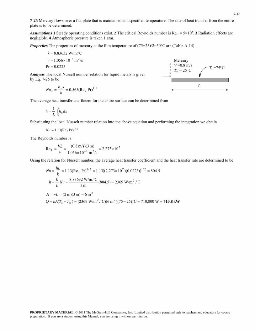
7-25 Mercury flows over a flat plate that is maintained at a specified temperature. The rate of heat transfer from the entire plate is to be determined.
Assumptions 1 Steady operating conditions exist. 2 The critical Reynolds number is Recr = 5×10⁵. 3 Radiation effects are negligible. 4 Atmospheric pressure is taken 1 atm.
Properties The properties of mercury at the film temperature of (75+25)/2=50°C are (Table A-14)
0223.0Pr
/sm 10056.1
C W/m.83632.827-
=×=
°=
ν
k
Mercury V =0.8 m/s T∞ = 25°C
L
Ts =75°C Analysis The local Nusselt number relation for liquid metals is given by Eq. 7-25 to be
2/1Pr)(Re565.0 xx
x kxh
Nu ==
The average heat transfer coefficient for the entire surface can be determined from
∫=L
x dxhL
h0
1
Substituting the local Nusselt number relation into the above equation and performing the integration we obtain
2/1Pr)(Re13.1 LNu =
The Reynolds number is
727
10273.2/sm 10056.1
m) m/s)(3 8.0(Re ×=×
==−ν
VLL
Using the relation for Nusselt number, the average heat transfer coefficient and the heat transfer rate are determined to be
C. W/m2369)5.804(
m 3C W/m.83632.8
5.804)]0223.0)(10273.2[(13.1Pr)(Re13.1
2
2/172/1
°=°
==
=×===
NuLkh
khLNu L
kW 710.8==°−°=−=
==
∞ W800,710C25))(75m C)(6. W/m2369()(
m 6=m) m)(3 2(22
2
TThAQ
wLA
s&
PROPRIETARY MATERIAL. © 2011 The McGraw-Hill Companies, Inc. Limited distribution permitted only to teachers and educators for course preparation. If you are a student using this Manual, you are using it without permission.
7-17
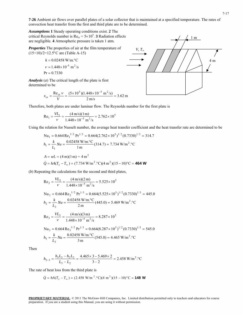
7-26 Ambient air flows over parallel plates of a solar collector that is maintained at a specified temperature. The rates of convection heat transfer from the first and third plate are to be determined.
Assumptions 1 Steady operating conditions exist. 2 The critical Reynolds number is Recr = 5×10⁵. 3 Radiation effects are negligible. 4 Atmospheric pressure is taken 1 atm.
Properties The properties of air at the film temperature of (15+10)/2=12.5°C are (Table A-15)
7330.0Pr
/sm 10448.1
C W/m.02458.025-
=×=
°=
ν
k
Analysis (a) The critical length of the plate is first determined to be
m 62.3m/s 2
/s)m 10448.1)(105(Re 255cr
cr =××
==−
Vx
ν
V, T∞
1 m
4 m
Therefore, both plates are under laminar flow. The Reynolds number for the first plate is
525
11 10762.2
/sm 10448.1m) m/s)(1 4(Re ×=
×==
−νVL
Using the relation for Nusselt number, the average heat transfer coefficient and the heat transfer rate are determined to be
C. W/m734.7)7.314(
m 1C W/m.02458.0
7.314)7330.0()10762.2(664.0PrRe664.0Nu
2
11
3/12/153/12/111
°=°
==
=×==
NuLkh
W464=°−°=−=
==
∞ C10))(15m C)(4. W/m734.7()(
m 4=m) m)(1 4(22
2
TThAQ
wLA
s&
(b) Repeating the calculations for the second and third plates,
525
22 10525.5
/sm 10448.1m) m/s)(2 4(Re ×=
×==
−νVL
C. W/m469.5)0.445(
m 2C W/m.02458.0
0.445)7330.0()10525.5(664.0PrRe664.0Nu
2
22
3/12/153/12/122
°=°
==
=×==
NuLkh
525
33 10287.8
/sm 10448.1m) m/s)(3 4(Re ×=
×==
−νVL
C. W/m465.4)0.545(
m 3C W/m.02458.0
0.545)7330.0()10287.8(664.0PrRe664.0Nu
2
33
3/12/153/12/133
°=°
==
=×==
NuLkh
Then
C. W/m458.223
2469.53465.4 2
23
223332 °=
−×−×
=−−
=− LLLhLh
h
The rate of heat loss from the third plate is
W148=°−°=−= ∞ C10))(15m C)(4. W/m458.2()( 22TThAQ s&

PROPRIETARY MATERIAL. © 2011 The McGraw-Hill Companies, Inc. Limited distribution permitted only to teachers and educators for course preparation. If you are a student using this Manual, you are using it without permission.
7-18
7-27 A car travels at a velocity of 80 km/h. The rate of heat transfer from the bottom surface of the hot automotive engine block is to be determined.
Assumptions 1 Steady operating conditions exist. 2 The critical Reynolds number is Recr = 5×10⁵. 3 Air is an ideal gas with constant properties. 4 The flow is turbulent over the entire surface because of the constant agitation of the engine block.
Properties The properties of air at 1 atm and the film temperature of (Ts + T∞)/2 = (100+20)/2 =60°C are (Table A-15)
7202.0Pr
/sm 10896.1
C W/m.02808.025-
=×=
°=
ν
kL = 0.8 m
Ts = 100°Cε = 0.95
Engine block
Air V = 80 km/h T∞ = 20°C
Analysis Air flows parallel to the 0.4 m side. The Reynolds number in this case is
525
10376.9/sm 10896.1
m) m/s](0.8 )3600/100080[(Re ×=×
×==
−∞
νLV
L
which is greater than the critical Reynolds number and thus the flow is laminar + turbulent. But the flow is assumed to be turbulent over the entire surface because of the constant agitation of the engine block. Using the proper relations, the Nusselt number, the heat transfer coefficient, and the heat transfer rate are determined to be
C. W/m78.69)1988(
m 8.0C W/m.02808.0
1988)7202.0()10376.9(037.0PrRe037.0
2
3/18.053/18.0
°=°
==
=×===
NuLkh
khLNu L
W1786=C20))(100m C)(0.32. W/m78.69()(
m 0.32=m) m)(0.4 8.0(22
2
°−°=−=
==
∞ ssconv
s
TThAQ
wLA&
The radiation heat transfer from the same surface is
W198=×=
−=
]K) 273+(25-K) 273+)[(100.K W/m10)(5.67m 32.0)(95.0(
)(44428-2
44surrssrad TTAQ σε&
Then the total rate of heat transfer from that surface becomes
W1984=+=+= W)1981786(radconvtotal QQQ &&&
PROPRIETARY MATERIAL. © 2011 The McGraw-Hill Companies, Inc. Limited distribution permitted only to teachers and educators for course preparation. If you are a student using this Manual, you are using it without permission.
7-19
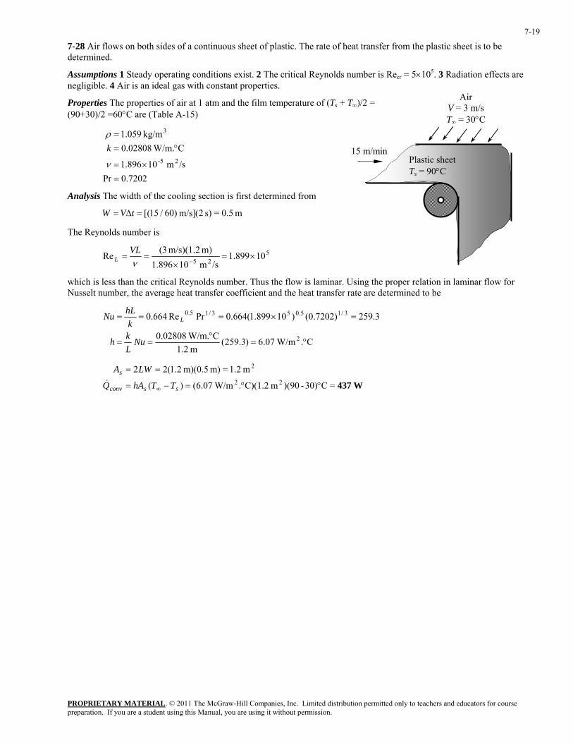
7-28 Air flows on both sides of a continuous sheet of plastic. The rate of heat transfer from the plastic sheet is to be determined.
Assumptions 1 Steady operating conditions exist. 2 The critical Reynolds number is Recr = 5×10⁵. 3 Radiation effects are negligible. 4 Air is an ideal gas with constant properties.
Air V = 3 m/s T∞ = 30°C
Properties The properties of air at 1 atm and the film temperature of (Ts + T∞)/2 = (90+30)/2 =60°C are (Table A-15)
15 m/min Plastic sheet Ts = 90°C
7202.0Pr/sm 10896.1
C W/m.02808.0kg/m 059.1
25-
3
=×=
°==
ν
ρk
Analysis The width of the cooling section is first determined from
m 0.5=s) 2(m/s] )60/15[(=∆= tVW
The Reynolds number is
525
10899.1/sm 10896.1
m) m/s)(1.2 (3Re ×=
×==
−νVL
L
which is less than the critical Reynolds number. Thus the flow is laminar. Using the proper relation in laminar flow for Nusselt number, the average heat transfer coefficient and the heat transfer rate are determined to be
C. W/m07.6)3.259(
m 2.1C W/m.02808.0
3.259)7202.0()10899.1(664.0PrRe664.0
2
3/15.053/15.0
°=°
==
=×===
NuLkh
khLNu L
W437=C30)-)(90m C)(1.2. W/m07.6()(
m 1.2=m) m)(0.5 2.1(2222
2
°°=−=
==
∞ ssconv
s
TThAQ
LWA&
PROPRIETARY MATERIAL. © 2011 The McGraw-Hill Companies, Inc. Limited distribution permitted only to teachers and educators for course preparation. If you are a student using this Manual, you are using it without permission.
7-20
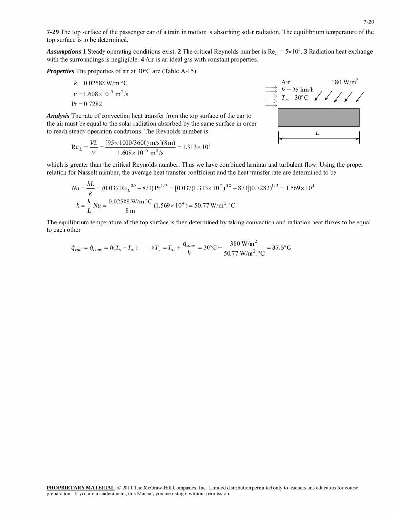
7-29 The top surface of the passenger car of a train in motion is absorbing solar radiation. The equilibrium temperature of the top surface is to be determined.
Assumptions 1 Steady operating conditions exist. 2 The critical Reynolds number is Recr = 5×10⁵. 3 Radiation heat exchange with the surroundings is negligible. 4 Air is an ideal gas with constant properties.
Properties The properties of air at 30°C are (Table A-15)
380 W/m2Air V = 95 km/h T∞ = 30°C
L
7282.0Pr
/sm 10608.1
C W/m.02588.025-
=×=
°=
ν
k
Analysis The rate of convection heat transfer from the top surface of the car to the air must be equal to the solar radiation absorbed by the same surface in order to reach steady operation conditions. The Reynolds number is
725 10313.1/sm 10608.1
m) m/s](8 1000/3600)95[Re ×=×
×==
−νVL
L
which is greater than the critical Reynolds number. Thus we have combined laminar and turbulent flow. Using the proper relation for Nusselt number, the average heat transfer coefficient and the heat transfer rate are determined to be
C. W/m77.50)10569.1(
m 8C W/m.02588.0
10569.1)7282.0](871)10313.1(037.0[Pr)871Re037.0(
24
43/18.073/18.0
°=×°
==
×=−×=−==
NuLkh
khLNu L
The equilibrium temperature of the top surface is then determined by taking convection and radiation heat fluxes to be equal to each other
C37.5°=°
°=+=⎯→⎯−== ∞∞ C. W/m77.50 W/m380+C30)( 2
2
hq
TTTThqq convssconvrad
&&&
PROPRIETARY MATERIAL. © 2011 The McGraw-Hill Companies, Inc. Limited distribution permitted only to teachers and educators for course preparation. If you are a student using this Manual, you are using it without permission.
7-21
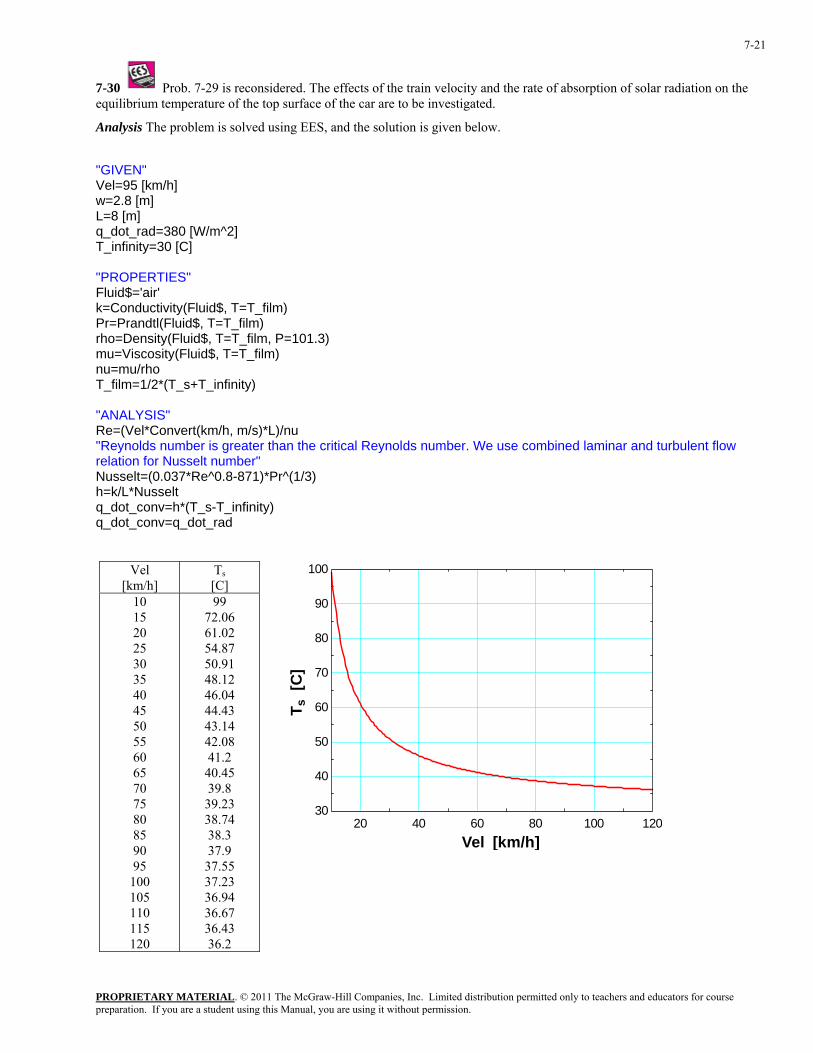
7-30 Prob. 7-29 is reconsidered. The effects of the train velocity and the rate of absorption of solar radiation on the equilibrium temperature of the top surface of the car are to be investigated.
Analysis The problem is solved using EES, and the solution is given below.
"GIVEN" Vel=95 [km/h] w=2.8 [m] L=8 [m] q_dot_rad=380 [W/m^2] T_infinity=30 [C] "PROPERTIES" Fluid$='air' k=Conductivity(Fluid$, T=T_film) Pr=Prandtl(Fluid$, T=T_film) rho=Density(Fluid$, T=T_film, P=101.3) mu=Viscosity(Fluid$, T=T_film) nu=mu/rho T_film=1/2*(T_s+T_infinity) "ANALYSIS" Re=(Vel*Convert(km/h, m/s)*L)/nu "Reynolds number is greater than the critical Reynolds number. We use combined laminar and turbulent flow relation for Nusselt number" Nusselt=(0.037*Re^0.8-871)*Pr^(1/3) h=k/L*Nusselt q_dot_conv=h*(T_s-T_infinity) q_dot_conv=q_dot_rad
Vel [km/h]
Ts [C]
10 15 20 25 30 35 40 45 50 55 60 65 70 75 80 85 90 95
100 105 110 115 120
99 72.06 61.02 54.87 50.91 48.12 46.04 44.43 43.14 42.08 41.2
40.45 39.8
39.23 38.74 38.3 37.9
37.55 37.23 36.94 36.67 36.43 36.2
20 40 60 80 100 12030
40
50
60
70
80
90
100
Vel [km/h]
T s [
C]

PROPRIETARY MATERIAL. © 2011 The McGraw-Hill Companies, Inc. Limited distribution permitted only to teachers and educators for course preparation. If you are a student using this Manual, you are using it without permission.
7-22
Qrad
[W/m2] Ts [C]
100 125 150 175 200 225 250 275 300 325 350 375 400 425 450 475 500
31.98 32.47 32.97 33.46 33.96 34.46 34.95 35.45 35.95 36.45 36.95 37.45 37.95 38.45 38.95 39.45 39.96
100 150 200 250 300 350 400 450 50032
34
36
38
40
qrad [W/m2]
T s [
C]
PROPRIETARY MATERIAL. © 2011 The McGraw-Hill Companies, Inc. Limited distribution permitted only to teachers and educators for course preparation. If you are a student using this Manual, you are using it without permission.
7-23
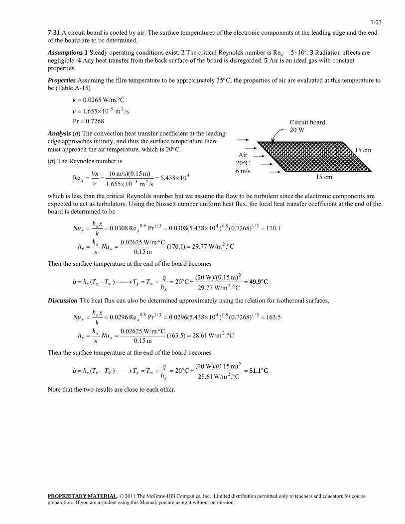
7-31 A circuit board is cooled by air. The surface temperatures of the electronic components at the leading edge and the end of the board are to be determined.
Assumptions 1 Steady operating conditions exist. 2 The critical Reynolds number is Recr = 5×10⁵. 3 Radiation effects are negligible. 4 Any heat transfer from the back surface of the board is disregarded. 5 Air is an ideal gas with constant properties.
Properties Assuming the film temperature to be approximately 35°C, the properties of air are evaluated at this temperature to be (Table A-15)
7268.0Pr
/sm 10655.1
C W/m.0265.025-
=×=
°=
ν
k
15 cm
Circuit b20 W
oard
Air 20°C 6 m/s
Analysis (a) The convection heat transfer coefficient at the leading edge approaches infinity, and thus the surface temperature there must approach the air temperature, which is 20°C.
(b) The Reynolds number is
425
10438.5/sm 10655.1
m) m/s)(0.15 6(Re ×=
×==
−νVx
x 15 cm
which is less than the critical Reynolds number but we assume the flow to be turbulent since the electronic components are expected to act as turbulators. Using the Nusselt number uniform heat flux, the local heat transfer coefficient at the end of the board is determined to be
C. W/m77.29)1.170(
m 15.0C W/m.02625.0
1.170)7268.0()10438.5(0308.0PrRe0308.0
2
3/18.043/18.0
°=°
==
=×===
xx
x
xx
x
Nux
kh
kxh
Nu
Then the surface temperature at the end of the board becomes
C49.9°=°
°=+=⎯→⎯−= ∞∞C. W/m77.29
m) W)/(0.15(20+C20)(2
2
xssx h
qTTTThq&
&
Discussion The heat flux can also be determined approximately using the relation for isothermal surfaces,
C. W/m61.28)5.163(
m 15.0C W/m.02625.0
5.163)7268.0()10438.5(0296.0PrRe0296.0
2
3/18.043/18.0
°=°
==
=×===
xx
x
xx
x
Nux
kh
kxh
Nu
Then the surface temperature at the end of the board becomes
C51.1°=°
°=+=⎯→⎯−= ∞∞C. W/m61.28
m) W)/(0.15(20+C20)(2
2
xssx h
qTTTThq&
&
Note that the two results are close to each other.
PROPRIETARY MATERIAL. © 2011 The McGraw-Hill Companies, Inc. Limited distribution permitted only to teachers and educators for course preparation. If you are a student using this Manual, you are using it without permission.
7-24
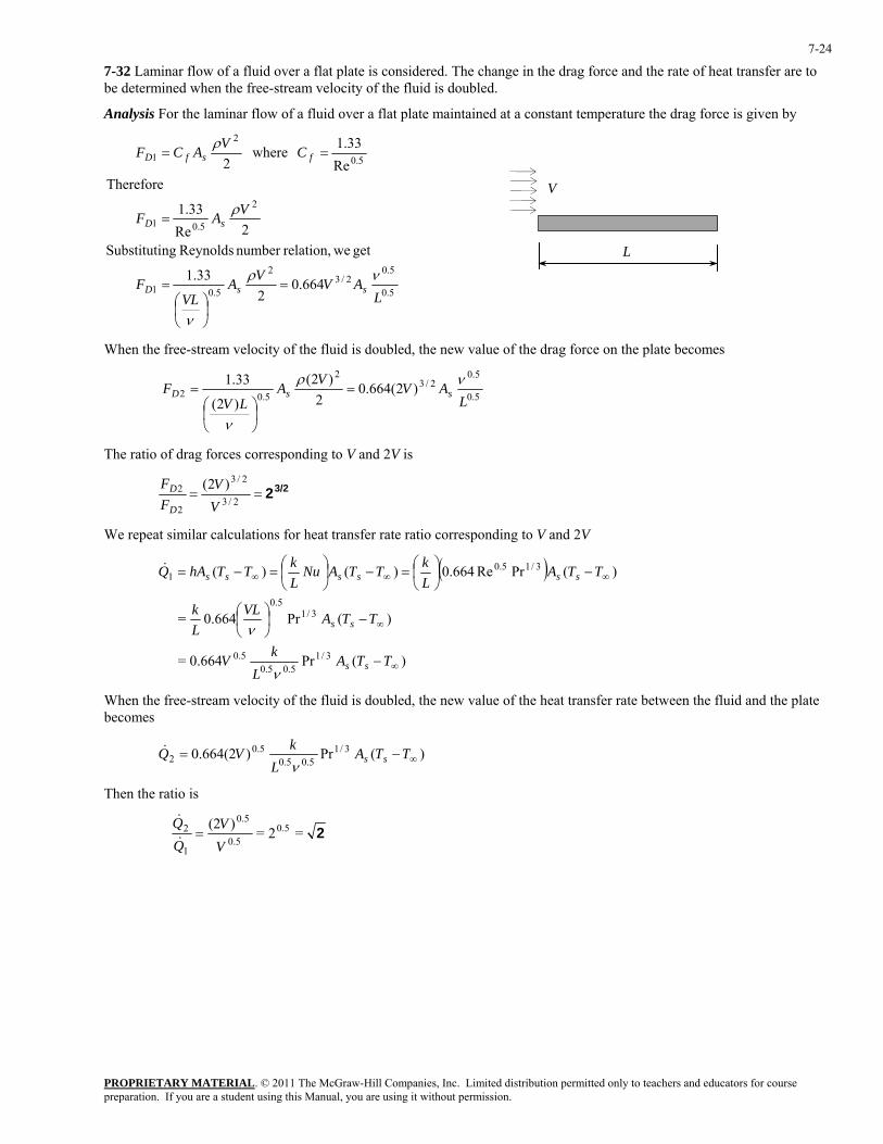
7-32 Laminar flow of a fluid over a flat plate is considered. The change in the drag force and the rate of heat transfer are to be determined when the free-stream velocity of the fluid is doubled.
Analysis For the laminar flow of a fluid over a flat plate maintained at a constant temperature the drag force is given by
5.0
5.02/3
2
5.01
2
5.01
5.0
2
1
664.02
33.1
get werelation,number Reynolds ngSubstituti2Re
33.1
ThereforeRe
33.1 where2
LAVVA
VLF
VAF
CVACF
ssD
sD
fsfD
νρ
ν
ρ
ρ
=
⎟⎠⎞
⎜⎝⎛
=
=
==
V
L
When the free-stream velocity of the fluid is doubled, the new value of the drag force on the plate becomes
5.0
5.02/3
2
5.02 )2(664.02
)2(
)2(
33.1 L
AVVALV
F ssDνρ
ν
=
⎟⎠
⎞⎜⎝
⎛=
The ratio of drag forces corresponding to V and 2V is
3/22==2/3
2/3
2
2 )2(VV
FF
D
D
We repeat similar calculations for heat transfer rate ratio corresponding to V and 2V
( )
)(Pr0.664=
)(Pr664.0=
)(PrRe664.0)()(
3/15.05.0
0.5
3/15.0
3/15.01
∞
∞
∞∞∞
−
−⎟⎠⎞
⎜⎝⎛
−⎟⎠⎞
⎜⎝⎛=−⎟
⎠⎞
⎜⎝⎛=−=
TTAL
kV
TTAVLLk
TTALkTTANu
LkTThAQ
ss
ss
ssssss
ν
ν
&
When the free-stream velocity of the fluid is doubled, the new value of the heat transfer rate between the fluid and the plate becomes
)(Pr)0.664(2 3/15.05.0
0.52 ∞−= TTA
LkVQ ssν
&
Then the ratio is
=2=)(2 0.50.5
0.5
1
2 2VV
=&
&
PROPRIETARY MATERIAL. © 2011 The McGraw-Hill Companies, Inc. Limited distribution permitted only to teachers and educators for course preparation. If you are a student using this Manual, you are using it without permission.
7-25
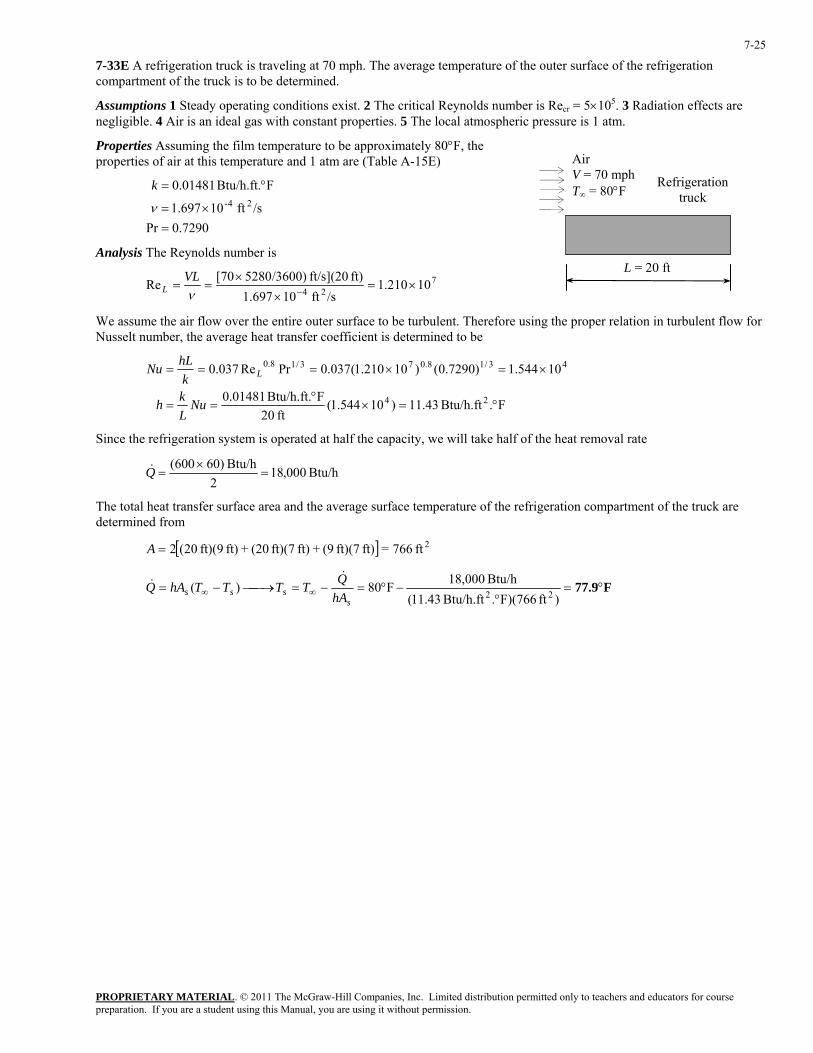
7-33E A refrigeration truck is traveling at 70 mph. The average temperature of the outer surface of the refrigeration compartment of the truck is to be determined.
Assumptions 1 Steady operating conditions exist. 2 The critical Reynolds number is Recr = 5×10⁵. 3 Radiation effects are negligible. 4 Air is an ideal gas with constant properties. 5 The local atmospheric pressure is 1 atm.
Properties Assuming the film temperature to be approximately 80°F, the properties of air at this temperature and 1 atm are (Table A-15E)
Refrigerationtruck
Air V = 70 mph T∞ = 80°F
7290.0Pr
/sft 10697.1
FBtu/h.ft. 01481.024-
=×=
°=
ν
k
Analysis The Reynolds number is L = 20 ft
724 10210.1/sft 10697.1
ft) ft/s](20 /3600)528070[Re ×=×
×==
−νVL
L
We assume the air flow over the entire outer surface to be turbulent. Therefore using the proper relation in turbulent flow for Nusselt number, the average heat transfer coefficient is determined to be
F.Btu/h.ft 43.11)10544.1(
ft 20FBtu/h.ft. 01481.0
10544.1)7290.0()10210.1(037.0PrRe037.0
24
43/18.073/18.0
°=×°
==
×=×===
NuLkh
khLNu L
Since the refrigeration system is operated at half the capacity, we will take half of the heat removal rate
Btu/h 000,182
Btu/h )60600(=
×=Q&
The total heat transfer surface area and the average surface temperature of the refrigeration compartment of the truck are determined from
[ ] 2ft 766=ft) ft)(7 (9+ft) ft)(7 (20+ft) ft)(9 20(2=A
F77.9°=°
−°=−=⎯→⎯−= ∞∞ )ft F)(766.Btu/h.ft 43.11(Btu/h 18,000F80)( 22
ssss hA
QTTTThAQ&
&
PROPRIETARY MATERIAL. © 2011 The McGraw-Hill Companies, Inc. Limited distribution permitted only to teachers and educators for course preparation. If you are a student using this Manual, you are using it without permission.
7-26
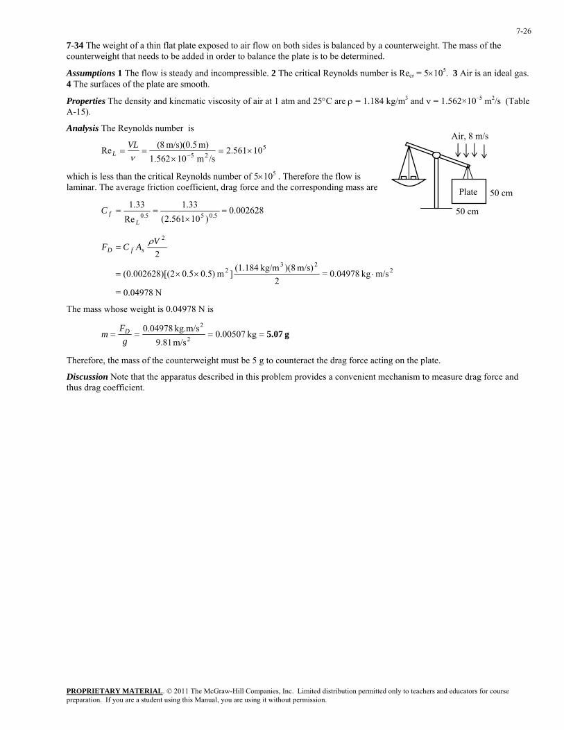
7-34 The weight of a thin flat plate exposed to air flow on both sides is balanced by a counterweight. The mass of the counterweight that needs to be added in order to balance the plate is to be determined.
Assumptions 1 The flow is steady and incompressible. 2 The critical Reynolds number is Recr = 5×10⁵. 3 Air is an ideal gas. 4 The surfaces of the plate are smooth.
Properties The density and kinematic viscosity of air at 1 atm and 25°C are ρ = 1.184 kg/m3 and ν = 1.562×10⁻⁵ m2/s (Table A-15).
Analysis The Reynolds number is Air, 8 m/s
Plate
50 cm
50 cm
525 10561.2/sm 10562.1
m) m/s)(0.5 8(Re ×=×
==−ν
VLL
which is less than the critical Reynolds number of 5×10⁵ . Therefore the flow is laminar. The average friction coefficient, drag force and the corresponding mass are
002628.0)10561.2(
33.1Re
33.15.055.0=
×==
LfC
N 0.04978=
m/skg 0.04978=2
m/s) )(8kg/m (1.184]m )5.05.02)[(002628.0(
2
223
2
2
⋅××=
=VACF sfD
ρ
The mass whose weight is 0.04978 N is
g 5.07==== kg 0.00507m/s 9.81kg.m/s 04978.0
2
2
gF
m D
Therefore, the mass of the counterweight must be 5 g to counteract the drag force acting on the plate.
Discussion Note that the apparatus described in this problem provides a convenient mechanism to measure drag force and thus drag coefficient.
PROPRIETARY MATERIAL. © 2011 The McGraw-Hill Companies, Inc. Limited distribution permitted only to teachers and educators for course preparation. If you are a student using this Manual, you are using it without permission.
7-27
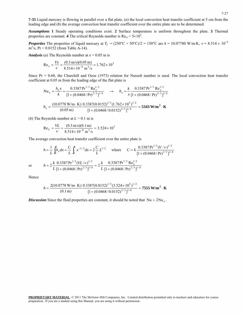
7-35 Liquid mercury is flowing in parallel over a flat plate, (a) the local convection heat transfer coefficient at 5 cm from the leading edge and (b) the average convection heat transfer coefficient over the entire plate are to be determined.
Assumptions 1 Steady operating conditions exist. 2 Surface temperature is uniform throughout the plate. 3 Thermal properties are constant. 4 The critical Reynolds number is Recr = 5×10⁵.
Properties The properties of liquid mercury at Tf = (250°C + 50°C)/2 = 150°C are k = 10.07780 W/m·K, ν = 8.514 × 10⁻⁸ m2/s, Pr = 0.0152 (from Table A-14).
Analysis (a) The Reynolds number at x = 0.05 m is
528 10762.1/sm 10514.8)m 05.0)(m/s 3.0(Re ×=
×==
−νVx
x
Since Pr < 0.60, the Churchill and Ozoe (1973) relation for Nusselt number is used. The local convection heat transfer coefficient at 0.05 m from the leading edge of the flat plate is
4/13/2
2/13/1
x ]Pr)/0468.0(1[RePr3387.0
Nu+
== xx
kxh
→ 4/13/2
2/13/1
]Pr)/0468.0(1[RePr3387.0
+= x
x xkh
K W/m5343 2 ⋅=+
×⋅= 4/13/2
2/153/1
])0152.0/0468.0(1[)10762.1()0152.0(3387.0
)m 05.0()K W/m0778.10(
xh
(b) The Reynolds number at L = 0.1 m is
528 10524.3/sm 10514.8)m 1.0)(m/s 3.0(Re ×=
×==
−νVL
L
The average convection heat transfer coefficient over the entire plate is
2/1
0
2/1
021 L
LCdxx
LCdxh
Lh
LLx === ∫∫ − where 4/13/2
2/13/1
]Pr)/0468.0(1[)/(Pr3387.0
+=
νVkC
or 4/13/2
2/13/1
4/13/2
2/13/1
]Pr)/0468.0(1[RePr3387.0
2]Pr)/0468.0(1[)/(Pr3387.02
+=
+= L
LkVL
Lkh ν
Hence
K W/m7555 2 ⋅=+
×⋅= 4/13/2
2/153/1
])0152.0/0468.0(1[)10524.3()0152.0(3387.0
)m 1.0()K W/m0778.10(2h
Discussion Since the fluid properties are constant, it should be noted that xNu2Nu = .

PROPRIETARY MATERIAL. © 2011 The McGraw-Hill Companies, Inc. Limited distribution permitted only to teachers and educators for course preparation. If you are a student using this Manual, you are using it without permission.
7-28
7-36 Liquid mercury flows in parallel over a 0.1-m long flat plate where there is an unheated starting length of 5 cm, (a) the local convection heat transfer coefficient at x = 0.1 m, (b) the average convection heat transfer coefficient for the heated section, and (c) the rate of heat transfer per unit width for the heated section are to be determined.
Assumptions 1 Steady operating conditions exist. 2 Surface temperature is uniform throughout the heated section. 3 Thermal properties are constant. 4 The critical Reynolds number is Recr = 5×10⁵.
Properties The properties of liquid mercury at Tf = (250°C + 50°C)/2 = 150°C are k = 10.07780 W/m·K, ν = 8.514 × 10⁻⁸ m2/s, Pr = 0.0152 (from Table A-14).
Analysis (a) Since Pr < 0.60, the Churchill and Ozoe (1973) relation is used for calculating the Nusselt number for ξ = 0. The local convection heat transfer coefficient at the trailing edge (x = 0.1 m) is calculated as follows:
528 10524.3/sm 10514.8)m 1.0)(m/s 3.0(Re ×=
×==
−= νVL
Lx (flow is laminar)
49.37])0152.0/0468.0(1[
)10524.3()0152.0(3387.0]Pr)/0468.0(1[
RePr3387.0Nu 4/13/2
2/153/1
4/13/2
2/13/1
)0for ( =+
×=
+= =
==Lx
Lx ξ
Hence,
3/14/3)0for (
])/(1[
NuNu
xx
xξ
ξ
−= = → 3/14/3
)0for (
])/(1[
Nu
xxkh x
xξ
ξ
−= =
K W/m5105 2 ⋅=−
⋅== 3/14/3 ])1.0/05.0(1[
49.37)m 1.0(
)K W/m0778.10(Lxh
(b) The average convection heat transfer coefficient over the heated section is
K W/m8278 2 ⋅=⋅−
−=
−−
= = )KW/m5105(1.0/05.01
])1.0/05.0(1[2/1
])/(1[2 24/34/3
hL
xh Lxξξ
(c) The rate of heat transfer per unit width for the heated section is
→ )()()( ss TTwLhTThAQ −−=−= ∞∞ ξ& ))((/ sTTLhwQ −−= ∞ξ&
W/m108.278 4×=−−⋅= K )50250)(m 05.0m 1.0)(K W/m8278(/ 2wQ&
Discussion For plate with unheated starting length, the thermal boundary layer does not begin to grow until the heated section, while the velocity boundary layer begins at the leading edge.
PROPRIETARY MATERIAL. © 2011 The McGraw-Hill Companies, Inc. Limited distribution permitted only to teachers and educators for course preparation. If you are a student using this Manual, you are using it without permission.
7-29
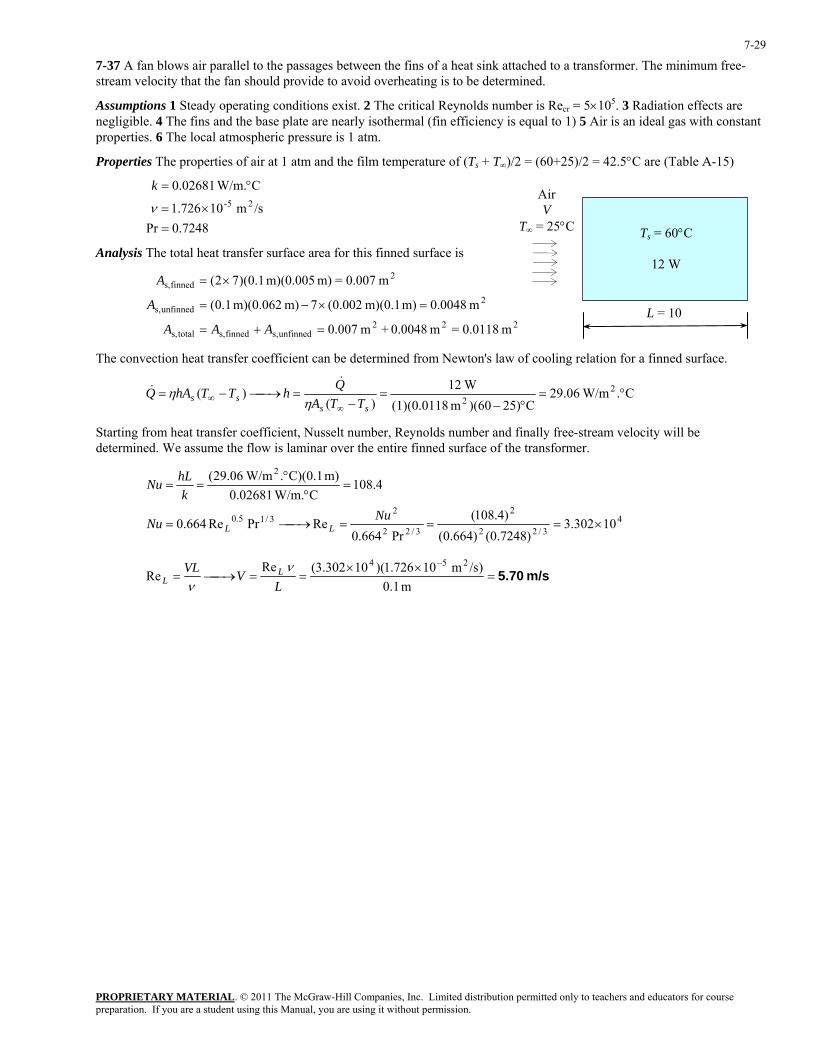
7-37 A fan blows air parallel to the passages between the fins of a heat sink attached to a transformer. The minimum free-stream velocity that the fan should provide to avoid overheating is to be determined.
Assumptions 1 Steady operating conditions exist. 2 The critical Reynolds number is Recr = 5×10⁵. 3 Radiation effects are negligible. 4 The fins and the base plate are nearly isothermal (fin efficiency is equal to 1) 5 Air is an ideal gas with constant properties. 6 The local atmospheric pressure is 1 atm.
Properties The properties of air at 1 atm and the film temperature of (Ts + T∞)/2 = (60+25)/2 = 42.5°C are (Table A-15)
7248.0Pr
/sm 10726.1
C W/m.02681.025-
=×=
°=
ν
k
Analysis The total heat transfer surface area for this finned surface is
222unfinneds,finneds,totals,
2unfinneds,
2finneds,
m 0.0118=m 0.0048+m 007.0
m 0.0048m) m)(0.1 002.0(7m) m)(0.062 1.0(
m 0.007=m) m)(0.005 1.0)(72(
=+=
=×−=
×=
AAA
A
A
Ts = 60°C
12 W
Air V
T∞ = 25°C
L = 10
The convection heat transfer coefficient can be determined from Newton's law of cooling relation for a finned surface.
C. W/m06.29C25))(60m (1)(0.0118
W12)(
)( 22
°=°−
=−
=⎯→⎯−=∞
∞ss
ss TTAQhTThAQ
ηη
&&
Starting from heat transfer coefficient, Nusselt number, Reynolds number and finally free-stream velocity will be determined. We assume the flow is laminar over the entire finned surface of the transformer.
4
3/22
2
3/22
23/15.0
2
10302.3)7248.0()664.0(
)4.108(Pr664.0
RePrRe664.0
4.108C W/m.02681.0
m) C)(0.1. W/m06.29(
×===⎯→⎯=
=°
°==
NuNu
khLNu
LL
m/s 5.70=××
==⎯→⎯=−
m 1.0)/sm 10726.1)(10302.3(Re
Re254
LVVL L
Lν
ν
PROPRIETARY MATERIAL. © 2011 The McGraw-Hill Companies, Inc. Limited distribution permitted only to teachers and educators for course preparation. If you are a student using this Manual, you are using it without permission.
7-30
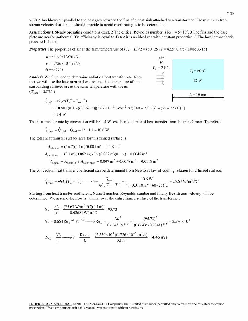
7-38 A fan blows air parallel to the passages between the fins of a heat sink attached to a transformer. The minimum free-stream velocity that the fan should provide to avoid overheating is to be determined.
Assumptions 1 Steady operating conditions exist. 2 The critical Reynolds number is Recr = 5×10⁵. 3 The fins and the base plate are nearly isothermal (fin efficiency is equal to 1) 4 Air is an ideal gas with constant properties. 5 The local atmospheric pressure is 1 atm.
Properties The properties of air at the film temperature of (Ts + T∞)/2 = (60+25)/2 = 42.5°C are (Table A-15)
7248.0Pr
/sm 10726.1
C W/m.02681.025-
=×=
°=
ν
k
Ts = 60°C
12 W
Air V
T∞ = 25°C
Analysis We first need to determine radiation heat transfer rate. Note that we will use the base area and we assume the temperature of the surrounding surfaces are at the same temperature with the air ( ) C25°=surrT
W1.4
]K) 27325(K) 27360)[(C. W/m1067.5(m)] m)(0.062 1.0)[(90.0(
)(4428
44
=+−+°×=
−=−
surrssrad TTAQ σε&
L = 10 cm
The heat transfer rate by convection will be 1.4 W less than total rate of heat transfer from the transformer. Therefore
W6.104.112radtotalconv =−=−= QQQ &&&
The total heat transfer surface area for this finned surface is
222
unfinneds,finneds,totals,
2unfinneds,
2finneds,
m 0.0118=m 0.0048+m 007.0
m 0.0048m) m)(0.1 002.0(7-m) m)(0.062 1.0(
m 0.007=m) m)(0.005 1.0)(72(
=+=
=×=
×=
AAA
A
A
The convection heat transfer coefficient can be determined from Newton's law of cooling relation for a finned surface.
C. W/m67.25C25)-)(60m (1)(0.0118
W6.10)(
)( 22
convconv °=
°=
−=⎯→⎯−=
∞∞
ssss TTA
QhTThAQ
ηη
&&
Starting from heat transfer coefficient, Nusselt number, Reynolds number and finally free-stream velocity will be determined. We assume the flow is laminar over the entire finned surface of the transformer.
4
3/22
2
3/22
23/15.0
2
10576.2)7248.0()664.0(
)73.95(Pr664.0
RePrRe664.0
73.95C W/m.02681.0
m) C)(0.1. W/m67.25(
×===⎯→⎯=
=°
°==
NuNu
khLNu
LL
m/s 4.45=××
==⎯→⎯=−
m 1.0)/sm 10726.1)(10576.2(Re
Re254
LVVL L
Lν
ν
PROPRIETARY MATERIAL. © 2011 The McGraw-Hill Companies, Inc. Limited distribution permitted only to teachers and educators for course preparation. If you are a student using this Manual, you are using it without permission.
7-31
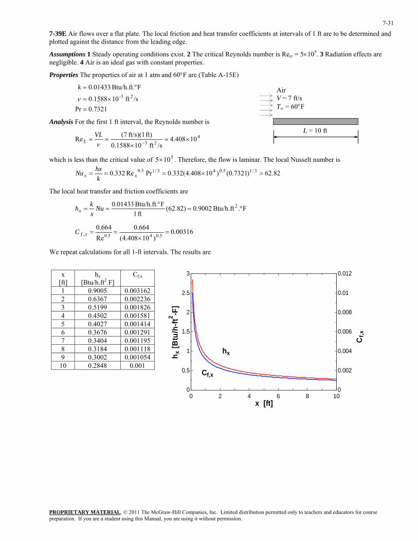
7-39E Air flows over a flat plate. The local friction and heat transfer coefficients at intervals of 1 ft are to be determined and plotted against the distance from the leading edge.
Assumptions 1 Steady operating conditions exist. 2 The critical Reynolds number is Recr = 5×10⁵. 3 Radiation effects are negligible. 4 Air is an ideal gas with constant properties.
Properties The properties of air at 1 atm and 60°F are (Table A-15E)
7321.0Pr
/sft 101588.0
FBtu/h.ft. 01433.023-
=×=
°=
ν
k Air V = 7 ft/s T∞ = 60°F
Analysis For the first 1 ft interval, the Reynolds number is L = 10 ft
423
10408.4/sft 101588.0
ft) ft/s)(1 7(Re ×=
×==
−νVL
L
which is less than the critical value of . Therefore, the flow is laminar. The local Nusselt number is
5105×
82.62)7321.0()10408.4(332.0PrRe332.0 3/15.043/15.0 =×=== xx khxNu
The local heat transfer and friction coefficients are
F.Btu/h.ft 9002.0)82.62(ft 1
FBtu/h.ft. 01433.0 2 °=°
== Nuxkhx
00316.0)10408.4(
664.0Re
664.05.045.0, =
×==xfC
We repeat calculations for all 1-ft intervals. The results are
x
[ft] hx
[Btu/h.ft2.F] Cf,x
1 0.9005 0.003162 2 0.6367 0.002236 3 0.5199 0.001826 4 0.4502 0.001581 5 0.4027 0.001414 6 0.3676 0.001291 7 0.3404 0.001195 8 0.3184 0.001118 9 0.3002 0.001054
10 0.2848 0.001
0 2 4 6 8 100
0.5
1
1.5
2
2.5
3
0
0.002
0.004
0.006
0.008
0.01
0.012
x [ft]
h x [B
tu/h
-ft2 -F
]
Cf,x
hx
Cf,x
PROPRIETARY MATERIAL. © 2011 The McGraw-Hill Companies, Inc. Limited distribution permitted only to teachers and educators for course preparation. If you are a student using this Manual, you are using it without permission.
7-32
7-40E Prob. 7-39E is reconsidered. The local friction and heat transfer coefficients along the plate are to be plotted against the distance from the leading edge.
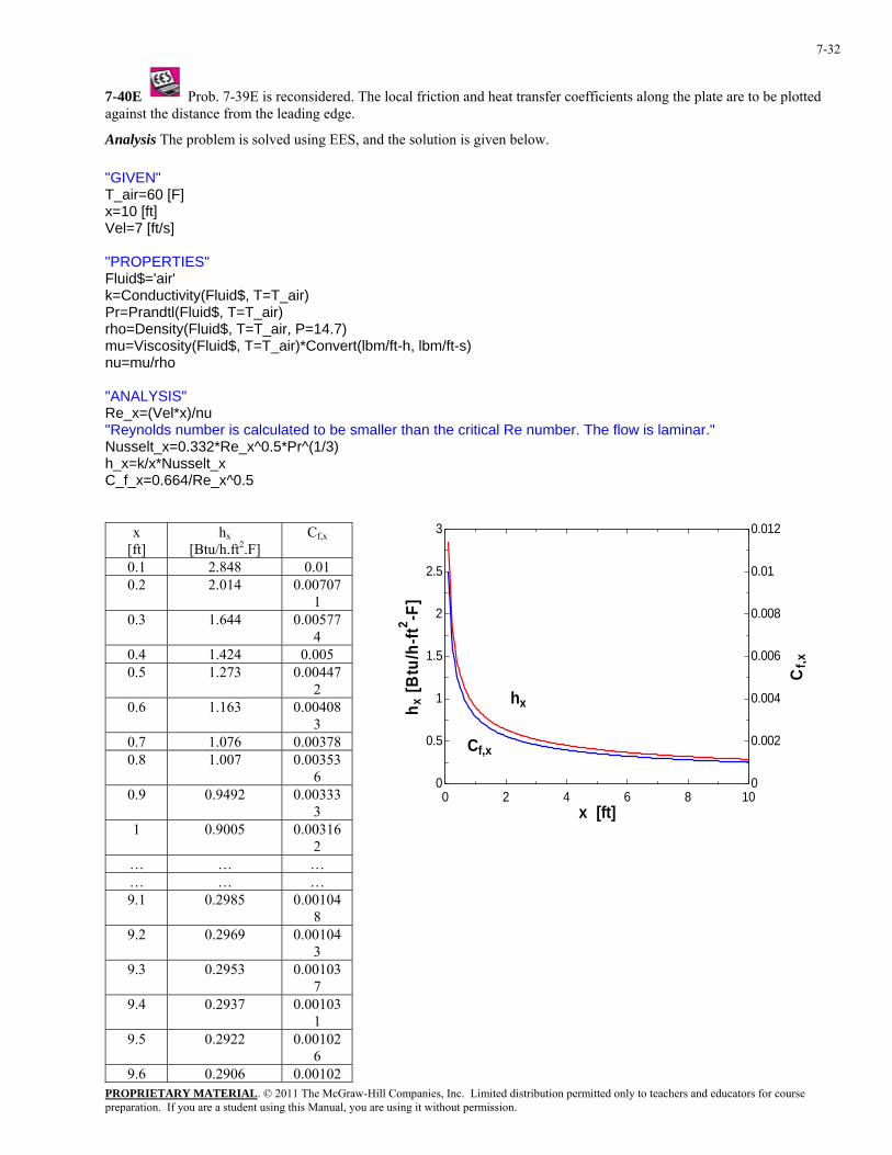
Analysis The problem is solved using EES, and the solution is given below. "GIVEN" T_air=60 [F] x=10 [ft] Vel=7 [ft/s] "PROPERTIES" Fluid$='air' k=Conductivity(Fluid$, T=T_air) Pr=Prandtl(Fluid$, T=T_air) rho=Density(Fluid$, T=T_air, P=14.7) mu=Viscosity(Fluid$, T=T_air)*Convert(lbm/ft-h, lbm/ft-s) nu=mu/rho "ANALYSIS" Re_x=(Vel*x)/nu "Reynolds number is calculated to be smaller than the critical Re number. The flow is laminar." Nusselt_x=0.332*Re_x^0.5*Pr^(1/3) h_x=k/x*Nusselt_x C_f_x=0.664/Re_x^0.5
x [ft]
hx [Btu/h.ft2.F]
Cf,x
0.1 2.848 0.01 0.2 2.014 0.00707
1 0.3 1.644 0.00577
4 0.4 1.424 0.005 0.5 1.273 0.00447
2 0.6 1.163 0.00408
3 0.7 1.076 0.00378 0.8 1.007 0.00353
6 0.9 0.9492 0.00333
3 1 0.9005 0.00316
2 … … … … … … 9.1 0.2985 0.00104
8 9.2 0.2969 0.00104
3 9.3 0.2953 0.00103
7 9.4 0.2937 0.00103
1 9.5 0.2922 0.00102
6 9.6 0.2906 0.00102
0 2 4 6 8 100
0.5
1
1.5
2
2.5
3
0
0.002
0.004
0.006
0.008
0.01
0.012
x [ft]
h x [B
tu/h
-ft2 -F
]
Cf,x
hx
Cf,x
PROPRIETARY MATERIAL. © 2011 The McGraw-Hill Companies, Inc. Limited distribution permitted only to teachers and educators for course preparation. If you are a student using this Manual, you are using it without permission.
7-33
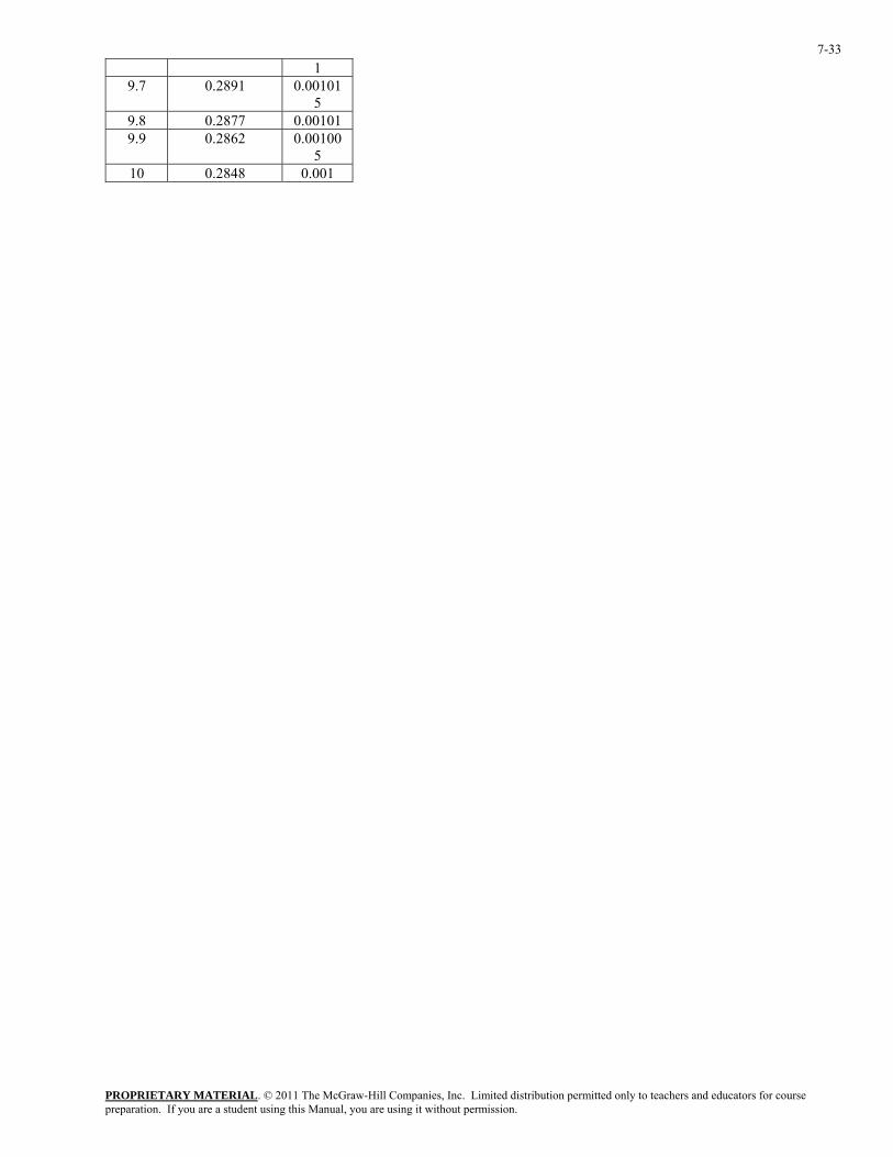
1 9.7 0.2891 0.00101
5 9.8 0.2877 0.00101 9.9 0.2862 0.00100
5 10 0.2848 0.001
PROPRIETARY MATERIAL. © 2011 The McGraw-Hill Companies, Inc. Limited distribution permitted only to teachers and educators for course preparation. If you are a student using this Manual, you are using it without permission.
7-34
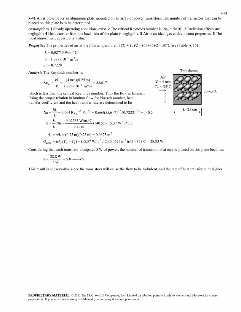
7-41 Air is blown over an aluminum plate mounted on an array of power transistors. The number of transistors that can be placed on this plate is to be determined. Assumptions 1 Steady operating conditions exist. 2 The critical Reynolds number is Recr = 5×10⁵. 3 Radiation effects are negligible 4 Heat transfer from the back side of the plate is negligible. 5 Air is an ideal gas with constant properties. 6 The local atmospheric pressure is 1 atm.
Properties The properties of air at the film temperature of (Ts + T∞)/2 = (65+35)/2 = 50°C are (Table A-15)
7228.0Pr
/sm 10798.1
C W/m.02735.025-
=×=
°=
ν
k
Transistors Analysis The Reynolds number is Air
V = 4 m/s T∞ = 35°C
617,55/sm 10798.1
m) m/s)(0.25 (4Re
25=
×==
−νVL
L
Ts=65°Cwhich is less than the critical Reynolds number. Thus the flow is laminar. Using the proper relation in laminar flow for Nusselt number, heat transfer coefficient and the heat transfer rate are determined to be
L=25 cm
C. W/m37.15)5.140(
m 25.0C W/m.02735.0
5.140)7228.0()617,55(664.0PrRe664.0
2
3/15.03/15.0
°=°
==
====
NuLkh
khLNu L
W28.83=C35))(65m C)(0.0625. W/m37.15()(
m 0.0625=m) m)(0.25 25.0(22
2
°−°=−=
==
∞ ssconv
s
TThAQ
wLA&
Considering that each transistor dissipates 5 W of power, the number of transistors that can be placed on this plate becomes
5⎯→⎯== 8.5 W5
W8.28n
This result is conservative since the transistors will cause the flow to be turbulent, and the rate of heat transfer to be higher.

PROPRIETARY MATERIAL. © 2011 The McGraw-Hill Companies, Inc. Limited distribution permitted only to teachers and educators for course preparation. If you are a student using this Manual, you are using it without permission.
7-35
7-42 Air is blown over an aluminum plate mounted on an array of power transistors. The number of transistors that can be placed on this plate is to be determined.
Assumptions 1 Steady operating conditions exist. 2 The critical Reynolds number is Recr = 5×10⁵. 3 Radiation effects are negligible 4 Heat transfer from the backside of the plate is negligible. 5 Air is an ideal gas with constant properties. 6 The local atmospheric pressure is 1 atm.
Properties The properties of air at 1 atm and the film temperature of (Ts + T∞)/2 = (65+35)/2 = 50°C are (Table A-15)
7228.0Pr
/sm 10798.1
C W/m.02735.025-
=×=
°=
ν
k
Transistors Air
V = 4 m/s T∞ = 35°C
Note that the atmospheric pressure will only affect the kinematic viscosity. The atmospheric pressure in atm is
Ts=65°C atm 823.0
kPa 101.325atm 1kPa) 4.83( ==P
The kinematic viscosity at this atmospheric pressure will be L=25 cm /sm 10184.2823.0/) /sm 10798.1( 2525 −− ×=×=ν
Analysis The Reynolds number is
425
10579.4/sm 10184.2
m) m/s)(0.25 (4Re ×=
×==
−νVL
L
which is less than the critical Reynolds number. Thus the flow is laminar. Using the proper relation in laminar flow for Nusselt number, the average heat transfer coefficient and the heat transfer rate are determined to be
C. W/m95.13)5.127(
m 25.0C W/m.02735.0
5.127)7228.0()10579.4(664.0PrRe664.0
2
3/15.043/15.0
°=°
==
=×===
NuLkh
khLNu L
W26.2=C35))(65m C)(0.0625. W/m95.13()(
m 0.0625=m) m)(0.25 25.0(22
conv
2
°−°=−=
==
∞ ss
s
TThAQ
wLA&
Considering that each transistor dissipates 5 W of power, the number of transistors that can be placed on this plate becomes
5⎯→⎯== 2.5 W5
W2.26n
This result is conservative since the transistors will cause the flow to be turbulent, and the rate of heat transfer to be higher.
PROPRIETARY MATERIAL. © 2011 The McGraw-Hill Companies, Inc. Limited distribution permitted only to teachers and educators for course preparation. If you are a student using this Manual, you are using it without permission.
7-36
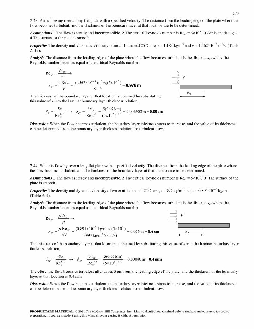
7-43 Air is flowing over a long flat plate with a specified velocity. The distance from the leading edge of the plate where the flow becomes turbulent, and the thickness of the boundary layer at that location are to be determined.
Assumptions 1 The flow is steady and incompressible. 2 The critical Reynolds number is Recr = 5×10⁵. 3 Air is an ideal gas. 4 The surface of the plate is smooth.
Properties The density and kinematic viscosity of air at 1 atm and 25°C are ρ = 1.184 kg/m3 and ν = 1.562×10⁻⁵ m2/s (Table A-15).
Analysis The distance from the leading edge of the plate where the flow becomes turbulent is the distance xcr where the Reynolds number becomes equal to the critical Reynolds number,
m 0.976=
××==
→=
−
m/s 8)105)(/sm 10562.1(Re
Re
525
Vx
Vx
crcr
crcr
νν V
xcrThe thickness of the boundary layer at that location is obtained by substituting this value of x into the laminar boundary layer thickness relation,
cm 0.69 m 006903.0)10(5m) 976.0(5
Re5
Re
52/152/12/1
==×
==→=cr
crcr
xx
xx δδ
Discussion When the flow becomes turbulent, the boundary layer thickness starts to increase, and the value of its thickness can be determined from the boundary layer thickness relation for turbulent flow.
7-44 Water is flowing over a long flat plate with a specified velocity. The distance from the leading edge of the plate where the flow becomes turbulent, and the thickness of the boundary layer at that location are to be determined.
Assumptions 1 The flow is steady and incompressible. 2 The critical Reynolds number is Recr = 5×10⁵. 3 The surface of the plate is smooth.
Properties The density and dynamic viscosity of water at 1 atm and 25°C are ρ = 997 kg/m3 and µ = 0.891×10⁻³ kg/m⋅s (Table A-9).
Analysis The distance from the leading edge of the plate where the flow becomes turbulent is the distance xcr where the Reynolds number becomes equal to the critical Reynolds number,
V
cm 5.6==×⋅×
==
→=
−
m 0.056m/s) )(8kg/m (997
)105)(skg/m 10891.0(Re
Re
3
53
Vx
Vx
crcr
crcr
ρµ
µρ
xcr
The thickness of the boundary layer at that location is obtained by substituting this value of x into the laminar boundary layer thickness relation,
mm 0.4 m 00040.0)10(5m) 056.0(5
Re5
Re
52/152/12/1
==×
==→=cr
crcr
xcr
xx δδ
Therefore, the flow becomes turbulent after about 5 cm from the leading edge of the plate, and the thickness of the boundary layer at that location is 0.4 mm.
Discussion When the flow becomes turbulent, the boundary layer thickness starts to increase, and the value of its thickness can be determined from the boundary layer thickness relation for turbulent flow.
PROPRIETARY MATERIAL. © 2011 The McGraw-Hill Companies, Inc. Limited distribution permitted only to teachers and educators for course preparation. If you are a student using this Manual, you are using it without permission.
7-37
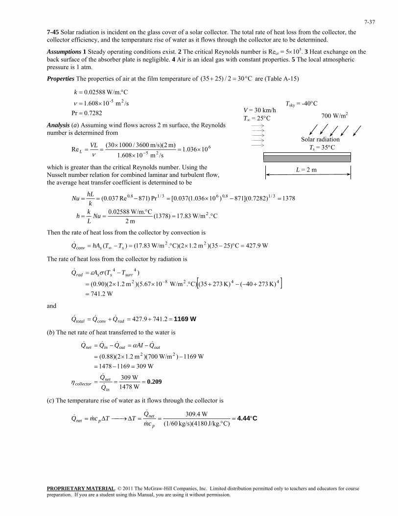
7-45 Solar radiation is incident on the glass cover of a solar collector. The total rate of heat loss from the collector, the collector efficiency, and the temperature rise of water as it flows through the collector are to be determined.
Assumptions 1 Steady operating conditions exist. 2 The critical Reynolds number is Recr = 5×10⁵. 3 Heat exchange on the back surface of the absorber plate is negligible. 4 Air is an ideal gas with constant properties. 5 The local atmospheric pressure is 1 atm.
Properties The properties of air at the film temperature of C 302/)2535( °=+ are (Table A-15)
7282.0Pr
/sm 10608.1
C W/m.02588.025-
=×=
°=
ν
k V = 30 km/h T∞ = 25°C
Tsky = -40°C
700 W/m2
Analysis (a) Assuming wind flows across 2 m surface, the Reynolds number is determined from
Solar radiation Ts = 35°C 6
2510036.1
/sm 10608.1m) m/s)(2 3600/100030(
Re ×=×
×==
−νVL
L
which is greater than the critical Reynolds number. Using the Nusselt number relation for combined laminar and turbulent flow, the average heat transfer coefficient is determined to be
L = 2 m
C. W/m83.17)1378(
m 2C W/m.02588.0
1378)7282.0](871)10036.1(037.0[Pr)871Re037.0(
2
3/18.063/18.0
°=°
==
=−×=−==
NuLkh
khLNu
Then the rate of heat loss from the collector by convection is
W9.427C25))(35m 1.2C)(2. W/m83.17()( 22 =°−×°=−= ∞ ssconv TThAQ&
The rate of heat loss from the collector by radiation is
[ ] W2.741
K) 27340(K) 27335()C. W/m1067.5()m 2.12)(90.0(
)(44282
44
=+−−+°××=
−=−
surrssrad TTAQ σε&
and
W1169=+=+= 2.7419.427radconvtotal QQQ &&&
(b) The net rate of heat transferred to the water is
0.209===
=−=−×=
−=−=
W1478 W309
W30911691478 W1169) W/m)(700m 2.12)(88.0( 22
in
netcollector
outoutinnet
QAIQQQ
&
&
&&&&
η
α
(c) The temperature rise of water as it flows through the collector is
C4.44°=°
==∆⎯→⎯∆=C)J/kg. kg/s)(4180 (1/60
W4.309
p
netpnet cm
QTTcmQ
&
&&&
PROPRIETARY MATERIAL. © 2011 The McGraw-Hill Companies, Inc. Limited distribution permitted only to teachers and educators for course preparation. If you are a student using this Manual, you are using it without permission.
7-38
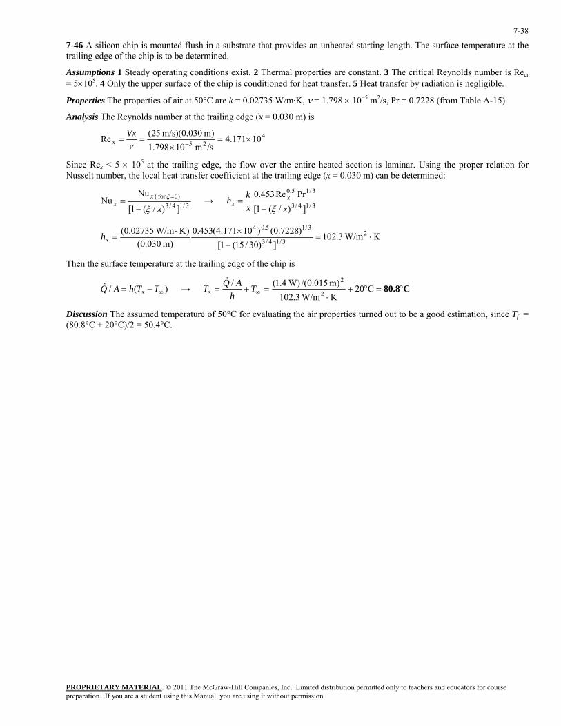
7-46 A silicon chip is mounted flush in a substrate that provides an unheated starting length. The surface temperature at the trailing edge of the chip is to be determined.
Assumptions 1 Steady operating conditions exist. 2 Thermal properties are constant. 3 The critical Reynolds number is Recr = 5×10⁵. 4 Only the upper surface of the chip is conditioned for heat transfer. 5 Heat transfer by radiation is negligible.
Properties The properties of air at 50°C are k = 0.02735 W/m·K, ν = 1.798 × 10⁻⁵ m2/s, Pr = 0.7228 (from Table A-15).
Analysis The Reynolds number at the trailing edge (x = 0.030 m) is
425 10171.4/sm 10798.1)m 030.0)(m/s 25(Re ×=
×==
−νVx
x
Since Rex < 5 × 10⁵ at the trailing edge, the flow over the entire heated section is laminar. Using the proper relation for Nusselt number, the local heat transfer coefficient at the trailing edge (x = 0.030 m) can be determined:
3/14/3)0for (
])/(1[
NuNu
xx
xξ
ξ
−= = → 3/14/3
3/15.0
])/(1[PrRe453.0
xxkh x
xξ−
=
K W/m3.102])30/15(1[
)7228.0()10171.4(453.0)m 030.0(
)K W/m02735.0( 23/14/3
3/15.04⋅=
−
×⋅=xh
Then the surface temperature at the trailing edge of the chip is
→ )(/ ∞−= TThAQ s& C80.8°=°+
⋅=+= ∞ C20
K W/m3.102)m 015.0/( W)4.1(/
2
2T
hAQTs
&
Discussion The assumed temperature of 50°C for evaluating the air properties turned out to be a good estimation, since Tf = (80.8°C + 20°C)/2 = 50.4°C.
PROPRIETARY MATERIAL. © 2011 The McGraw-Hill Companies, Inc. Limited distribution permitted only to teachers and educators for course preparation. If you are a student using this Manual, you are using it without permission.
7-39
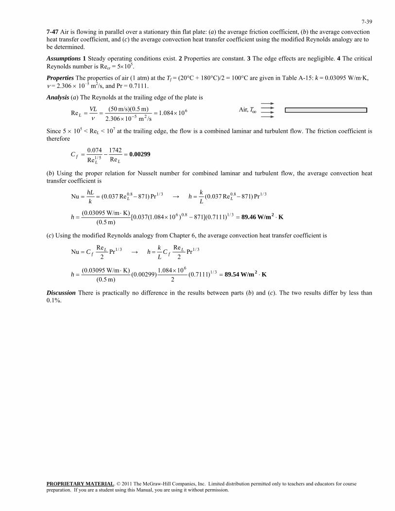
7-47 Air is flowing in parallel over a stationary thin flat plate: (a) the average friction coefficient, (b) the average convection heat transfer coefficient, and (c) the average convection heat transfer coefficient using the modified Reynolds analogy are to be determined.
Assumptions 1 Steady operating conditions exist. 2 Properties are constant. 3 The edge effects are negligible. 4 The critical Reynolds number is Recr = 5×10⁵.
Properties The properties of air (1 atm) at the Tf = (20°C + 180°C)/2 = 100°C are given in Table A-15: k = 0.03095 W/m·K, ν = 2.306 × 10⁻⁵ m2/s, and Pr = 0.7111.
Analysis (a) The Reynolds at the trailing edge of the plate is
625 10084.1/sm 10306.2)m 5.0)(m/s 50(Re ×=
×==
−νVL
L
Since 5 × 10⁵ < ReL < 107 at the trailing edge, the flow is a combined laminar and turbulent flow. The friction coefficient is therefore
0.00299=−=LL
fCRe1742
Re074.0
5/1
(b) Using the proper relation for Nusselt number for combined laminar and turbulent flow, the average convection heat transfer coefficient is
3/18.0 Pr)871Re037.0(Nu −== LkhL → 3/18.0 Pr)871Re037.0( −= LL
kh
K W/m89.46 2 ⋅=−×⋅
= 3/18.06 )7111.0](871)10084.1(037.0[)m 5.0(
K) W/m03095.0(h
(c) Using the modified Reynolds analogy from Chapter 6, the average convection heat transfer coefficient is
3/1Pr2
ReNu L
fC= → 3/1Pr2
Re LfC
Lkh =
K W/m89.54 2 ⋅=×⋅
= 3/16
)7111.0(2
10084.1)00299.0()m 5.0(
K) W/m03095.0(h
Discussion There is practically no difference in the results between parts (b) and (c). The two results differ by less than 0.1%.
PROPRIETARY MATERIAL. © 2011 The McGraw-Hill Companies, Inc. Limited distribution permitted only to teachers and educators for course preparation. If you are a student using this Manual, you are using it without permission.
7-40
Flow across Cylinders and Spheres
7-48C Friction drag is due to the shear stress at the surface whereas the pressure drag is due to the pressure differential between the front and back sides of the body when a wake is formed in the rear.
7-49C Turbulence moves the fluid separation point further back on the rear of the body, reducing the size of the wake, and thus the magnitude of the pressure drag (which is the dominant mode of drag). As a result, the drag coefficient suddenly drops. In general, turbulence increases the drag coefficient for flat surfaces, but the drag coefficient usually remains constant at high Reynolds numbers when the flow is turbulent.
7-50C For the laminar flow, the heat transfer coefficient will be the highest at the stagnation point which corresponds to °≈ 0θ . In turbulent flow, on the other hand, it will be highest when θ is between . °° 120 and 90
7-51C Flow separation in flow over a cylinder is delayed in turbulent flow because of the extra mixing due to random fluctuations and the transverse motion.
PROPRIETARY MATERIAL. © 2011 The McGraw-Hill Companies, Inc. Limited distribution permitted only to teachers and educators for course preparation. If you are a student using this Manual, you are using it without permission.
7-41
7-52 A heated long cylindrical rod is placed in a cross flow of air. The rod surface has an emissivity of 0.95 and its surface temperature is to be determined.
Assumptions 1 Steady operating conditions exist. 2 Properties are constant. 3 The surface temperature is constant. 4 heat flux dissipated from the rod is uniform.
Properties The properties of air (1 atm) at 70°C are given in Table A-15: k = 0.02881 W/m·K, ν = 1.995 × 10⁻⁵ m2/s, and Pr = 0.7177.
Analysis The Reynolds number for the air flowing across the rod is
2506/sm 10995.1)m 005.0)(m/s 10(Re 25 =
×==
−νVD
D
Using the Churchill and Bernstein relation for Nusselt number, the convection heat transfer coefficient is
5/48/5
4/13/2
3/12/1
cyl 282000Re1
]Pr)/4.0(1[PrRe62.03.0Nu
⎥⎥⎦
⎤
⎢⎢⎣
⎡⎟⎠⎞
⎜⎝⎛+
++==
khD
K W/m3.148
28200025061
])7177.0/4.0(1[)7177.0()2506(62.03.0
m 0050K W/m02881.0
2
5/48/5
4/13/2
3/12/1
⋅=
⎪⎭
⎪⎬⎫
⎪⎩
⎪⎨⎧
⎥⎥⎦
⎤
⎢⎢⎣
⎡⎟⎠⎞
⎜⎝⎛+
++
⋅=
.h
From energy balance, we obtain
→ radconv2 W/m16000 qq && += )()( W/m16000 4
surr42 TTTTh ss −+−= ∞ εσ
Copy the following line and paste on a blank EES screen to solve the above equation: h=148.3 epsilon=0.95 sigma=5.670e-8 T_inf=20+273 T_surr=20+273 16000=h*(T_s-T_inf)+epsilon*sigma*(T_s^4-T_surr^4)
Solving by EES software, the surface temperature of the rod is C122°== K 395sT
Discussion Note that absolute temperatures must be used in calculations involving the radiation heat transfer equation.
PROPRIETARY MATERIAL. © 2011 The McGraw-Hill Companies, Inc. Limited distribution permitted only to teachers and educators for course preparation. If you are a student using this Manual, you are using it without permission.
7-42
7-53 Air is flowing over a 5-cm diameter sphere, (a) the average drag coefficient on the sphere and (b) the heat transfer rate from the sphere are to be determined.
Assumptions 1 Steady operating conditions exist. 2 Properties are constant. 3 The surface temperature is constant.
Properties The properties of air (1 atm) at the free stream temperature T∞ = 20°C (Table A-15): ρ = 1.204 kg/m3, k = 0.02514 W/m·K, µ = 1.825 × 10⁻⁵ kg/m·s, and Pr = 0.7309; at the surface temperature Ts = 80°C: µs = 2.096 × 10⁻⁵ kg/m·s; at the film temperature Tf = (80°C + 20°C)/2 = 50°C: ρ = 1.092 kg/m3 and ν = 1.798 × 10⁻⁵ m2/s.
Analysis (a) The Reynolds number for air properties evaluated from the film temperature is
9733skg/m 10798.1
)m 05.0)(m/s 5.3(Re 5 =⋅×
==−ν
VDD
From Fig. 7-17, the average drag coefficient is 0.4≈DC .
(b) The Reynolds number for air properties evaluated from the free stream temperature is
55
310155.1
skg/m 10825.1)m 05.0)(m/s 5.3)(kg/m 204.1(Re ×=
⋅×==
−µρVD
D
Using the Whitaker relation for Nusselt number, the convection heat transfer coefficient is
4/1
4.03/22/1sph Pr]Re06.0Re4.0[2Nu ⎟⎟
⎠
⎞⎜⎜⎝
⎛++== ∞
skhD
µµ
76.64096.2825.1)7309.0]()10155.1(06.0)10155.1(4.0[2Nu
4/14.03/242/14
sph =⎪⎭
⎪⎬⎫
⎪⎩
⎪⎨⎧
⎟⎠⎞
⎜⎝⎛×+×+=
Hence
K W/m56.32m 050
K W/m02514.076.64 2 ⋅=⎟⎠⎞
⎜⎝⎛ ⋅
=.
h
The heat transfer rate from the sphere is
W15.34=−⋅=−=−= ∞∞ K )2080()m 05.0()K W/m56.32()()( 222 ππ TTDhTThAQ ss&
Discussion If the difference in the free stream temperature and the surface temperature is small, then the assumption that µ∞ / µs ≈ 1 is appropriate.
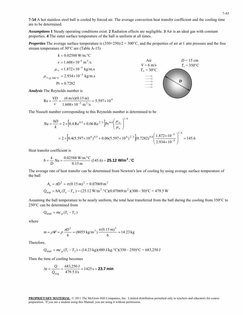
PROPRIETARY MATERIAL. © 2011 The McGraw-Hill Companies, Inc. Limited distribution permitted only to teachers and educators for course preparation. If you are a student using this Manual, you are using it without permission.
7-43
7-54 A hot stainless steel ball is cooled by forced air. The average convection heat transfer coefficient and the cooling time are to be determined.
Assumptions 1 Steady operating conditions exist. 2 Radiation effects are negligible. 3 Air is an ideal gas with constant properties. 4 The outer surface temperature of the ball is uniform at all times.
Properties The average surface temperature is (350+250)/2 = 300°C, and the properties of air at 1 atm pressure and the free stream temperature of 30°C are (Table A-15)
7282.0Pr
kg/m.s 10934.2
kg/m.s 10872.1
/sm 10608.1
C W/m.02588.0
5C 300@,
5
25-
=
×=
×=
×=
°=
−°
−∞
s
k
µ
µ
ν D = 15 cm Ts = 350°C
D
Air V = 6 m/s T∞ = 30°C
Analysis The Reynolds number is
425
10597.5/sm 10608.1
m) m/s)(0.15 (6Re ×=
×==
−νVD
The Nusselt number corresponding to this Reynolds number is determined to be
[ ]
[ ] 6.14510934.210872.1)7282.0()10597.5(06.0)10597.5(4.02
PrRe06.0Re4.02
4/1
5
54.03/245.04
4/14.03/25.0
=⎟⎟⎠
⎞⎜⎜⎝
⎛
×
××+×+=
⎟⎟⎠
⎞⎜⎜⎝
⎛++==
−
−
∞
skhDNu
µµ
Heat transfer coefficient is
C. W/m25.12 2 °=°
== )6.145(m 15.0
C W/m.02588.0NuDkh
The average rate of heat transfer can be determined from Newton's law of cooling by using average surface temperature of the ball
W479.5=C30))(300m C)(0.07069. W/m12.25()(
m 0.07069=m) 15.0(22
222
°−°=−=
==
∞TThAQ
DA
ssavg
s
&
ππ
Assuming the ball temperature to be nearly uniform, the total heat transferred from the ball during the cooling from 350°C to 250°C can be determined from
)( 21total TTmcQ p −=
where
kg 23.146
m) (0.15)kg/m 8055(6
33
3====
ππρρ Dm V
Therefore,
J 683,250=C250)C)(350J/kg. kg)(480 23.14()( 21total °−°=−= TTmcQ p
Then the time of cooling becomes
min 23.7====∆ s 1425J/s 5.479
J 250,683
avgQQt&
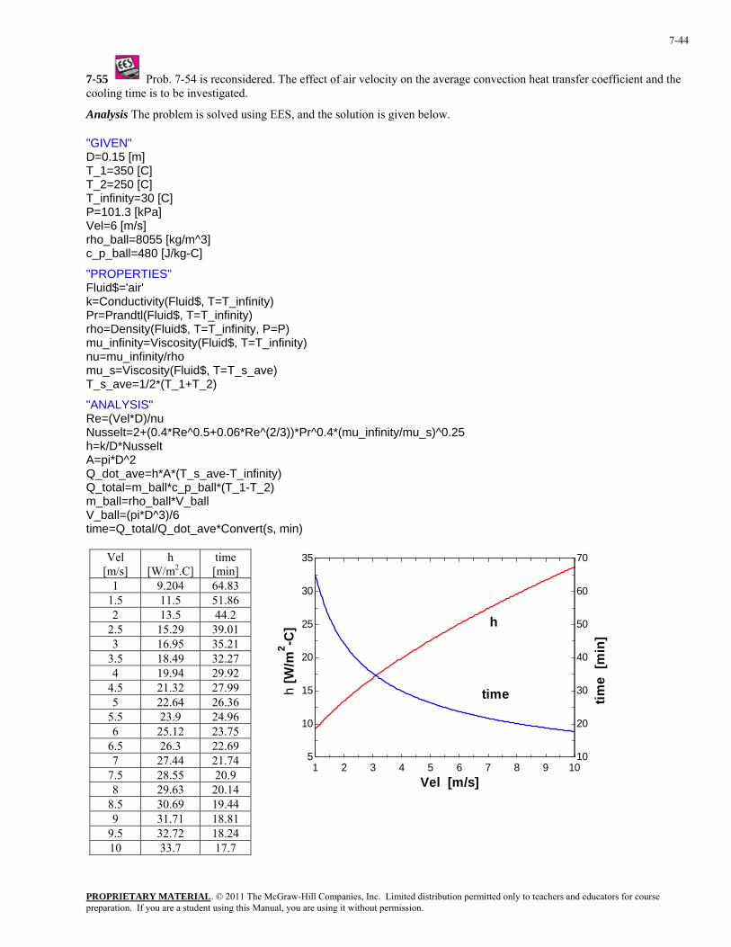
PROPRIETARY MATERIAL. © 2011 The McGraw-Hill Companies, Inc. Limited distribution permitted only to teachers and educators for course preparation. If you are a student using this Manual, you are using it without permission.
7-44
7-55 Prob. 7-54 is reconsidered. The effect of air velocity on the average convection heat transfer coefficient and the cooling time is to be investigated.
Analysis The problem is solved using EES, and the solution is given below.
"GIVEN" D=0.15 [m] T_1=350 [C] T_2=250 [C] T_infinity=30 [C] P=101.3 [kPa] Vel=6 [m/s] rho_ball=8055 [kg/m^3] c_p_ball=480 [J/kg-C]
"PROPERTIES" Fluid$='air' k=Conductivity(Fluid$, T=T_infinity) Pr=Prandtl(Fluid$, T=T_infinity) rho=Density(Fluid$, T=T_infinity, P=P) mu_infinity=Viscosity(Fluid$, T=T_infinity) nu=mu_infinity/rho mu_s=Viscosity(Fluid$, T=T_s_ave) T_s_ave=1/2*(T_1+T_2)
"ANALYSIS" Re=(Vel*D)/nu Nusselt=2+(0.4*Re^0.5+0.06*Re^(2/3))*Pr^0.4*(mu_infinity/mu_s)^0.25 h=k/D*Nusselt A=pi*D^2 Q_dot_ave=h*A*(T_s_ave-T_infinity) Q_total=m_ball*c_p_ball*(T_1-T_2) m_ball=rho_ball*V_ball V_ball=(pi*D^3)/6 time=Q_total/Q_dot_ave*Convert(s, min)
Vel [m/s]
h [W/m2.C]
time [min]
1 9.204 64.83 1.5 11.5 51.86 2 13.5 44.2
2.5 15.29 39.01 3 16.95 35.21
3.5 18.49 32.27 4 19.94 29.92
4.5 21.32 27.99 5 22.64 26.36
5.5 23.9 24.96 6 25.12 23.75
6.5 26.3 22.69 7 27.44 21.74
7.5 28.55 20.9 8 29.63 20.14
8.5 30.69 19.44 9 31.71 18.81
9.5 32.72 18.24 10 33.7 17.7
1 2 3 4 5 6 7 8 9 105
10
15
20
25
30
35
10
20
30
40
50
60
70
Vel [m/s]
h [W
/m2 -C
]
time
[min
]h
time
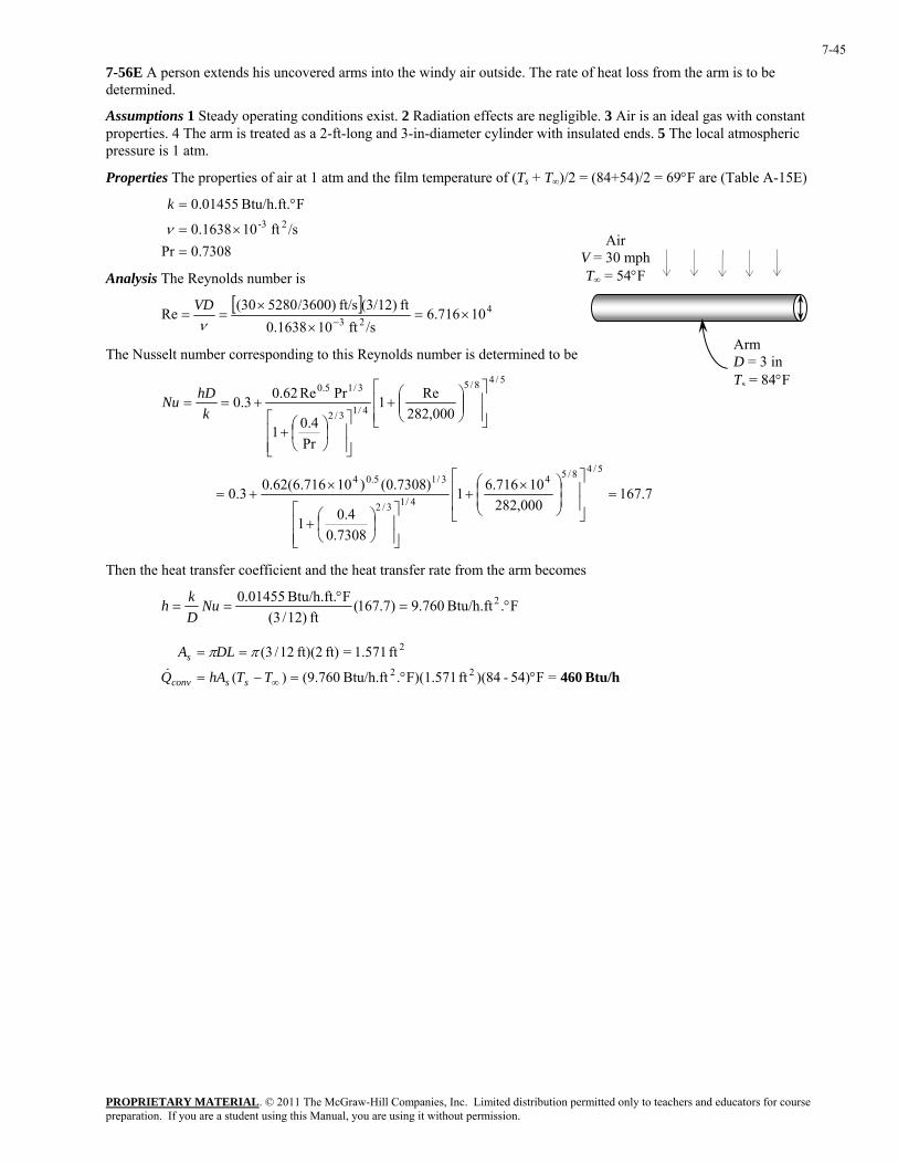
PROPRIETARY MATERIAL. © 2011 The McGraw-Hill Companies, Inc. Limited distribution permitted only to teachers and educators for course preparation. If you are a student using this Manual, you are using it without permission.
7-45
7-56E A person extends his uncovered arms into the windy air outside. The rate of heat loss from the arm is to be determined.
Assumptions 1 Steady operating conditions exist. 2 Radiation effects are negligible. 3 Air is an ideal gas with constant properties. 4 The arm is treated as a 2-ft-long and 3-in-diameter cylinder with insulated ends. 5 The local atmospheric pressure is 1 atm.
Properties The properties of air at 1 atm and the film temperature of (Ts + T∞)/2 = (84+54)/2 = 69°F are (Table A-15E)
7308.0Pr
/sft 101638.0
FBtu/h.ft. 01455.023-
=×=
°=
ν
k
Air V = 30 mph T∞ = 54°F Analysis The Reynolds number is
[ ] 423 10716.6/sft 101638.0
ft (3/12)ft/s /3600)5280(30Re ×=×
×==
−νVD
The Nusselt number corresponding to this Reynolds number is determined to be
7.167000,282
10716.61
7308.04.01
)7308.0()10716.6(62.03.0
000,282Re1
Pr4.01
PrRe62.03.0
5/48/54
4/13/2
3/15.04
5/48/5
4/13/2
3/15.0
=⎥⎥
⎦
⎤
⎢⎢
⎣
⎡
⎟⎟⎠
⎞⎜⎜⎝
⎛ ×+
⎥⎥⎦
⎤
⎢⎢⎣
⎡⎟⎠⎞
⎜⎝⎛+
×+=
⎥⎥⎦
⎤
⎢⎢⎣
⎡⎟⎟⎠
⎞⎜⎜⎝
⎛+
⎥⎥⎦
⎤
⎢⎢⎣
⎡⎟⎠⎞
⎜⎝⎛+
+==k
hDNu
Arm D = 3 in Ts = 84°F
Then the heat transfer coefficient and the heat transfer rate from the arm becomes
F.Btu/h.ft 760.9)7.167(ft )12/3(
FBtu/h.ft. 01455.0 2 °=°
== NuDkh
Btu/h 460=F54)-)(84ft F)(1.571.Btu/h.ft 760.9()(
ft 1.571=ft) ft)(2 12/3(22
2
°°=−=
==
∞TThAQ
DLA
ssconv
s
&
ππ

PROPRIETARY MATERIAL. © 2011 The McGraw-Hill Companies, Inc. Limited distribution permitted only to teachers and educators for course preparation. If you are a student using this Manual, you are using it without permission.
7-46
7-57E Prob. 7-56E is reconsidered. The effects of air temperature and wind velocity on the rate of heat loss from the arm are to be investigated.
Analysis The problem is solved using EES, and the solution is given below.
"GIVEN" T_infinity=54 [F] Vel=30 [mph] T_s=84 [F] L=2 [ft] D=(3/12) [ft] "PROPERTIES" Fluid$='air' k=Conductivity(Fluid$, T=T_film) Pr=Prandtl(Fluid$, T=T_film) rho=Density(Fluid$, T=T_film, P=14.7) mu=Viscosity(Fluid$, T=T_film)*Convert(lbm/ft-h, lbm/ft-s) nu=mu/rho T_film=1/2*(T_s+T_infinity) "ANALYSIS" Re=(Vel*Convert(mph, ft/s)*D)/nu Nusselt=0.3+(0.62*Re^0.5*Pr^(1/3))/(1+(0.4/Pr)^(2/3))^0.25*(1+(Re/282000)^(5/8))^(4/5) h=k/D*Nusselt A=pi*D*L Q_dot_conv=h*A*(T_s-T_infinity)
T∞ [F]
Qconv [Btu/h]
20 25 30 35 40 45 50 55 60 65 70 75 80
990.6 911.9 833.3 755.1 677
599.2 521.6 444.3 367.2 290.3 213.6 137.1 60.86
20 30 40 50 60 70 800
100
200
300
400
500
600
700
800
900
1000
T∞ [F]
Qco
nv [
Btu
/h]
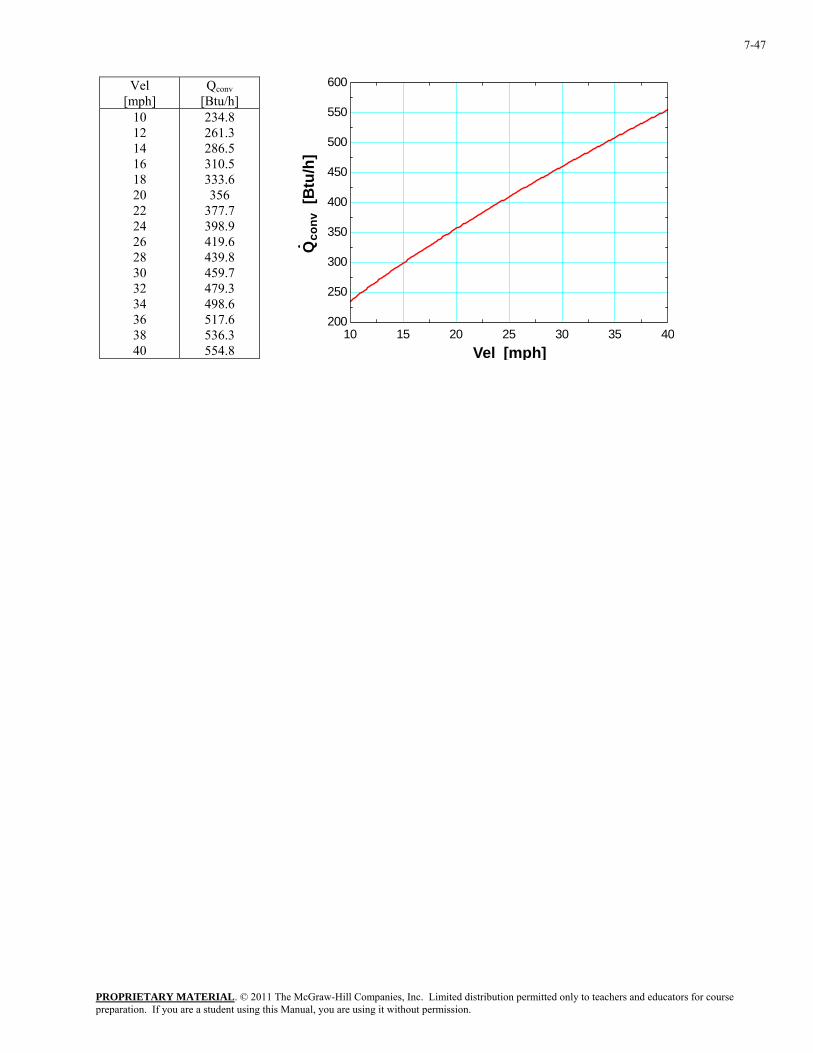
PROPRIETARY MATERIAL. © 2011 The McGraw-Hill Companies, Inc. Limited distribution permitted only to teachers and educators for course preparation. If you are a student using this Manual, you are using it without permission.
7-47
Vel
[mph] Qconv
[Btu/h] 10 12 14 16 18 20 22 24 26 28 30 32 34 36 38 40
234.8 261.3 286.5 310.5 333.6 356
377.7 398.9 419.6 439.8 459.7 479.3 498.6 517.6 536.3 554.8
10 15 20 25 30 35 40200
250
300
350
400
450
500
550
600
Vel [mph]
Qco
nv [
Btu
/h]
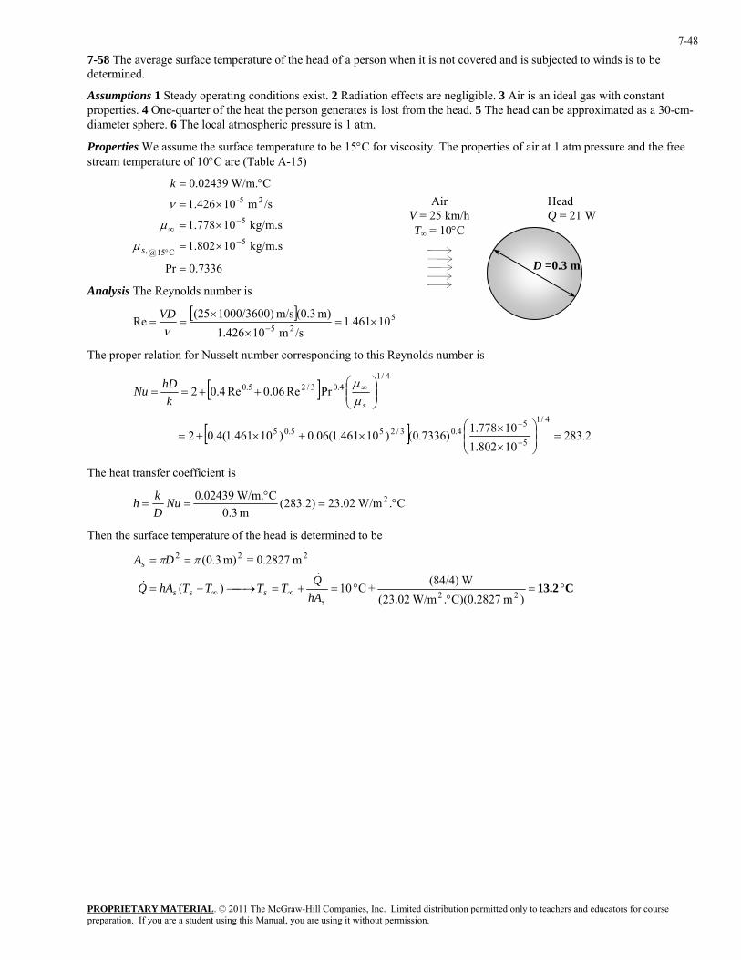
PROPRIETARY MATERIAL. © 2011 The McGraw-Hill Companies, Inc. Limited distribution permitted only to teachers and educators for course preparation. If you are a student using this Manual, you are using it without permission.
7-48
7-58 The average surface temperature of the head of a person when it is not covered and is subjected to winds is to be determined.
Assumptions 1 Steady operating conditions exist. 2 Radiation effects are negligible. 3 Air is an ideal gas with constant properties. 4 One-quarter of the heat the person generates is lost from the head. 5 The head can be approximated as a 30-cm-diameter sphere. 6 The local atmospheric pressure is 1 atm.
Properties We assume the surface temperature to be 15°C for viscosity. The properties of air at 1 atm pressure and the free stream temperature of 10°C are (Table A-15)
7336.0Pr
kg/m.s 10802.1
kg/m.s 10778.1
/sm 10426.1
C W/m.02439.0
5C15@,
5
25-
=
×=
×=
×=
°=
−°
−∞
s
k
µ
µ
ν Air V = 25 km/h T∞ = 10°C
Head Q = 21 W
D =0.3 m
Analysis The Reynolds number is
[ ] 5
2510461.1
/sm 10426.1m) (0.3m/s 1000/3600)(25
Re ×=×
×==
−νVD
The proper relation for Nusselt number corresponding to this Reynolds number is
[ ]
[ ] 2.28310802.110778.1)7336.0()10461.1(06.0)10461.1(4.02
PrRe06.0Re4.02
4/1
5
54.03/255.05
4/14.03/25.0
=⎟⎟⎠
⎞⎜⎜⎝
⎛
×
××+×+=
⎟⎟⎠
⎞⎜⎜⎝
⎛++==
−
−
∞
skhDNu
µµ
The heat transfer coefficient is
C. W/m23.02)2.283(m 3.0
C W/m.02439.0 2 °=°
== NuDkh
Then the surface temperature of the head is determined to be
C 13.2 °=
°°=+=⎯→⎯−=
==
∞∞)m C)(0.2827. W/m02.23(
W(84/4)+C 10)(
m 0.2827=m) 3.0(
22
222
ssss
s
hAQTTTThAQ
DA&
&
ππ

PROPRIETARY MATERIAL. © 2011 The McGraw-Hill Companies, Inc. Limited distribution permitted only to teachers and educators for course preparation. If you are a student using this Manual, you are using it without permission.
7-49
7-59 The flow of a fluid across an isothermal cylinder is considered. The change in the drag force and the rate of heat transfer when the free-stream velocity of the fluid is doubled is to be determined.
Analysis The drag force on a cylinder is given by
Air V → 2V
PipeD Ts
2
2
1VACF NDDρ
=
When the free-stream velocity of the fluid is doubled, the drag force becomes
2
)2( 2
2V
ACF NDDρ
=
Taking the ratio of them yields
4==2
2
1
2 )2(VV
FF
D
D
The rate of heat transfer between the fluid and the cylinder is given by Newton's law of cooling. We assume the Nusselt number is proportional to the nth power of the Reynolds number with 0.33 < n < 0.805. Then,
( )
)(
)(
)(Re)()(1
∞
∞
∞∞∞
−⎟⎠⎞
⎜⎝⎛=
−⎟⎠⎞
⎜⎝⎛=
−=−⎟⎠⎞
⎜⎝⎛=−=
TTADDkV
TTAVDDk
TTADkTTANu
DkTThAQ
ss
nn
ss
n
ssn
ssss
ν
ν
&
When the free-stream velocity of the fluid is doubled, the heat transfer rate becomes
)()2(2 ∞−⎟⎠⎞
⎜⎝⎛= TTAD
DkVQ s
nn
ν&
Taking the ratio of them yields
n2==n
n
VV
QQ )2(
1
2&
&
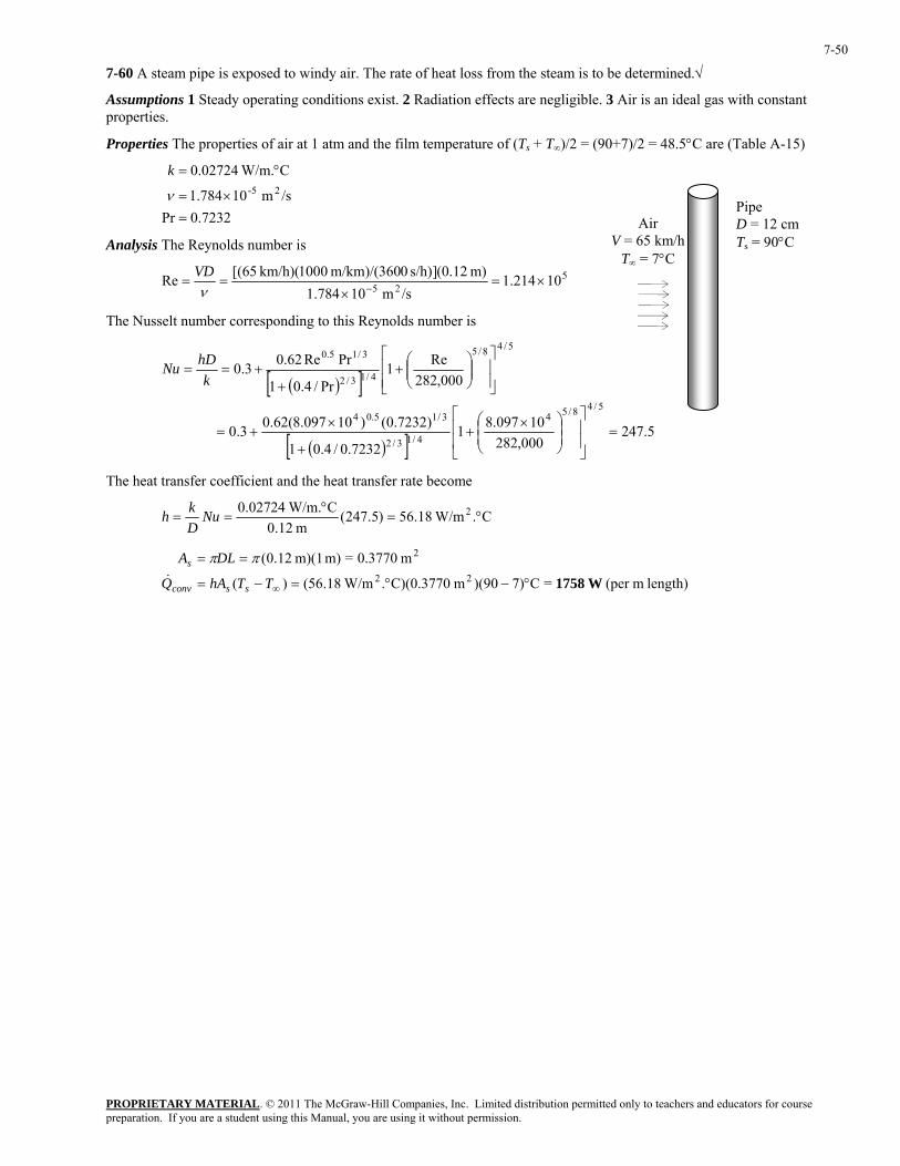
PROPRIETARY MATERIAL. © 2011 The McGraw-Hill Companies, Inc. Limited distribution permitted only to teachers and educators for course preparation. If you are a student using this Manual, you are using it without permission.
7-50
7-60 A steam pipe is exposed to windy air. The rate of heat loss from the steam is to be determined.√
Assumptions 1 Steady operating conditions exist. 2 Radiation effects are negligible. 3 Air is an ideal gas with constant properties.
Properties The properties of air at 1 atm and the film temperature of (Ts + T∞)/2 = (90+7)/2 = 48.5°C are (Table A-15)
7232.0Pr
/sm 10784.1
C W/m.02724.025-
=×=
°=
ν
k
Analysis The Reynolds number is
525 10214.1/sm 10784.1
m) (0.12]s/h) 0m/km)/(360 1000(km/h) (65[Re ×=×
==−ν
VD
The Nusselt number corresponding to this Reynolds number is
( )[ ]
( )[ ] 5.247000,282
10097.817232.0/4.01
)7232.0()10097.8(62.03.0
000,282Re1
Pr/4.01
PrRe62.03.0
5/48/54
4/13/2
3/15.04
5/48/5
4/13/2
3/15.0
=⎥⎥
⎦
⎤
⎢⎢
⎣
⎡
⎟⎟⎠
⎞⎜⎜⎝
⎛ ×+
+
×+=
⎥⎥⎦
⎤
⎢⎢⎣
⎡⎟⎟⎠
⎞⎜⎜⎝
⎛+
++==
khDNu
Air V = 65 km/h
T∞ = 7°C
Pipe D = 12 cT
m 90°C s =
The heat transfer coefficient and the heat transfer rate become
C. W/m18.56)5.247(m 12.0
C W/m.02724.0 2 °=°
== NuDkh
length) m(per =C7))(90m C)(0.3770. W/m18.56()(
m 0.3770=m) m)(1 12.0(22
2
W1758°−°=−=
==
∞TThAQ
DLA
ssconv
s
&
ππ
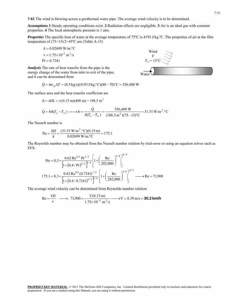
PROPRIETARY MATERIAL. © 2011 The McGraw-Hill Companies, Inc. Limited distribution permitted only to teachers and educators for course preparation. If you are a student using this Manual, you are using it without permission.
7-51
7-61 The wind is blowing across a geothermal water pipe. The average wind velocity is to be determined.
Assumptions 1 Steady operating conditions exist. 2 Radiation effects are negligible. 3 Air is an ideal gas with constant properties. 4 The local atmospheric pressure is 1 atm.
Properties The specific heat of water at the average temperature of 75ºC is 4193 J/kg.ºC. The properties of air at the film temperature of (75+15)/2=45ºC are (Table A-15)
7241.0Pr
/sm 1075.1
C W/m.02699.025-
=×=
°=
ν
k
Water
Wind V
T∞ = 15°C
Analysis The rate of heat transfer from the pipe is the energy change of the water from inlet to exit of the pipe, and it can be determined from
W56,4003C)70C)(80J/kg. kg/s)(4193 5.8( =°−°=∆= TcmQ p&&
The surface area and the heat transfer coefficient are 2m 188.5=m) m)(400 15.0(ππ == DLA
C. W/m51.31C)1575)(m (188.5
W356,400)(
)( 22
°=°−
=−
=⎯→⎯−=∞
∞ TTAQhTThAQ
ss
&&
The Nusselt number is
1.175C W/m.02699.0
m) C)(0.15. W/m51.31( 2=
°°
==k
hDNu
The Reynolds number may be obtained from the Nusselt number relation by trial-error or using an equation solver such as EES:
( )[ ]
( )[ ] 900,71Re000,282
Re17241.0/4.01
)7241.0(Re62.03.0175.1
000,282Re1
Pr/4.01
PrRe62.03.0
5/48/5
4/13/2
3/15.0
5/48/5
4/13/2
3/15.0
=⎯→⎯⎥⎥⎦
⎤
⎢⎢⎣
⎡⎟⎟⎠
⎞⎜⎜⎝
⎛+
++=
⎥⎥⎦
⎤
⎢⎢⎣
⎡⎟⎟⎠
⎞⎜⎜⎝
⎛+
++=Nu
The average wind velocity can be determined from Reynolds number relation
km/h 30.2==⎯→⎯×
=⎯→⎯=−
m/s 39.8/sm 1075.1
m) (0.15900,71 Re
25V
VVDν

PROPRIETARY MATERIAL. © 2011 The McGraw-Hill Companies, Inc. Limited distribution permitted only to teachers and educators for course preparation. If you are a student using this Manual, you are using it without permission.
7-52
7-62 The wind is blowing across the wire of a transmission line. The surface temperature of the wire is to be determined.
Assumptions 1 Steady operating conditions exist. 2 Radiation effects are negligible. 3 Air is an ideal gas with constant properties. 4 The local atmospheric pressure is 1 atm.
Properties We assume the film temperature to be 10°C. The properties of air at this temperature are (Table A-15)
7336.0Pr/sm 10426.1
C W/m.02439.0kg/m 246.1
25-
3
=×=
°==
ν
ρk
Analysis The Reynolds number is
[ ] 4870/sm 10426.1
m) (0.005m/s 0/3600)100(50Re 25 =×
×==
−νVD
The Nusselt number corresponding to this Reynolds number is determined to be
( )[ ]
( )[ ] 80.36000,282
487017336.0/4.01
)7336.0()4870(62.03.0
000,282Re1
Pr/4.01
PrRe62.03.0
5/48/5
4/13/2
3/15.0
5/48/5
4/13/2
3/15.0
=⎥⎥⎦
⎤
⎢⎢⎣
⎡⎟⎟⎠
⎞⎜⎜⎝
⎛+
++=
⎥⎥⎦
⎤
⎢⎢⎣
⎡⎟⎟⎠
⎞⎜⎜⎝
⎛+
++==
khDNu
Wind V = 50 km/hT∞ = 10°C
Transmission wire, TsD = 0.5 cm
The heat transfer coefficient is
C. W/m5.179)80.36(m 005.0
C W/m.02439.0 2 °=°
== NuDkh
The rate of heat generated in the electrical transmission lines per meter length is
W5.0=Ohm) (0.002A) 50( 22 === RIQW &&
The entire heat generated in electrical transmission line has to be transferred to the ambient air. The surface temperature of the wire then becomes
2m 0.01571=m) m)(1 005.0(ππ == DLAs
C11.8°=°
°=+=⎯→⎯−= ∞∞ )m C)(0.01571. W/m5.179( W5+C10)( 22
ssss hA
QTTTThAQ&
&
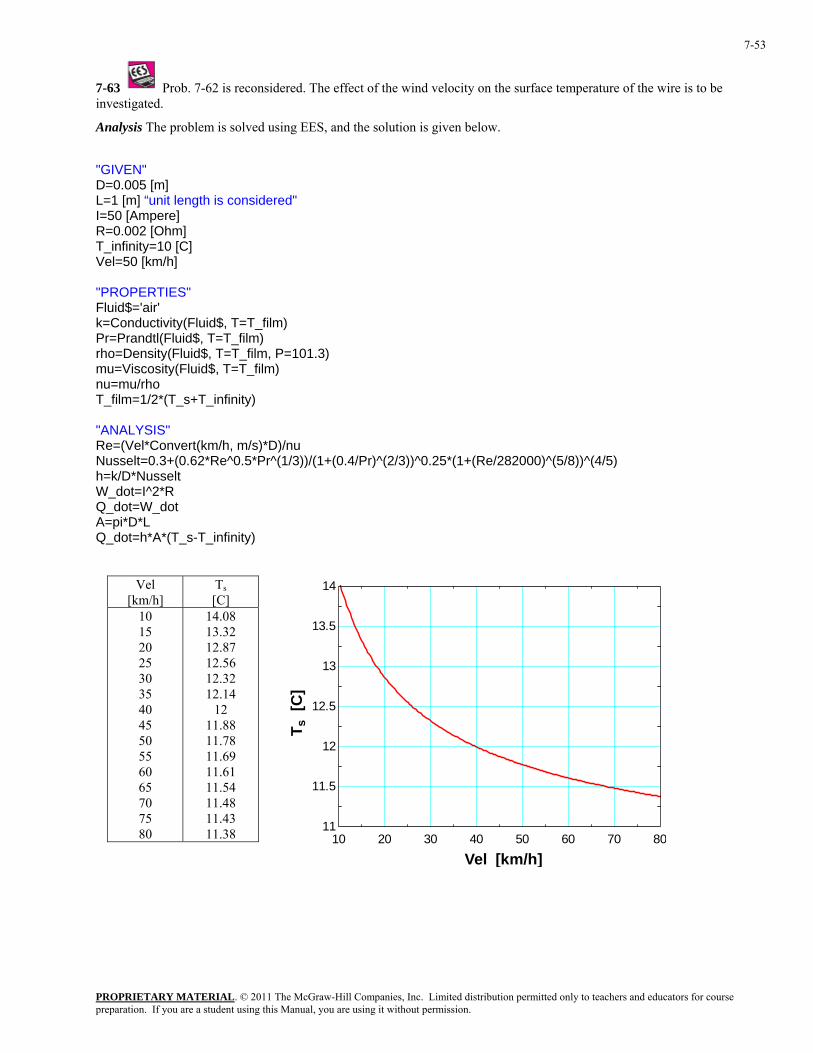
PROPRIETARY MATERIAL. © 2011 The McGraw-Hill Companies, Inc. Limited distribution permitted only to teachers and educators for course preparation. If you are a student using this Manual, you are using it without permission.
7-53
7-63 Prob. 7-62 is reconsidered. The effect of the wind velocity on the surface temperature of the wire is to be investigated.
Analysis The problem is solved using EES, and the solution is given below.
"GIVEN" D=0.005 [m] L=1 [m] “unit length is considered" I=50 [Ampere] R=0.002 [Ohm] T_infinity=10 [C] Vel=50 [km/h] "PROPERTIES" Fluid$='air' k=Conductivity(Fluid$, T=T_film) Pr=Prandtl(Fluid$, T=T_film) rho=Density(Fluid$, T=T_film, P=101.3) mu=Viscosity(Fluid$, T=T_film) nu=mu/rho T_film=1/2*(T_s+T_infinity) "ANALYSIS" Re=(Vel*Convert(km/h, m/s)*D)/nu Nusselt=0.3+(0.62*Re^0.5*Pr^(1/3))/(1+(0.4/Pr)^(2/3))^0.25*(1+(Re/282000)^(5/8))^(4/5) h=k/D*Nusselt W_dot=I^2*R Q_dot=W_dot A=pi*D*L Q_dot=h*A*(T_s-T_infinity)
Vel [km/h]
Ts [C]
10 15 20 25 30 35 40 45 50 55 60 65 70 75 80
14.08 13.32 12.87 12.56 12.32 12.14
12 11.88 11.78 11.69 11.61 11.54 11.48 11.43 11.38 10 20 30 40 50 60 70 80
11
11.5
12
12.5
13
13.5
14
Vel [km/h]
T s [
C]
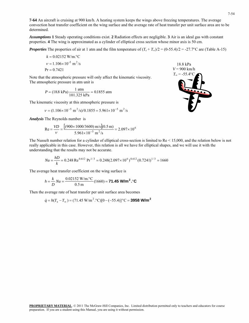
PROPRIETARY MATERIAL. © 2011 The McGraw-Hill Companies, Inc. Limited distribution permitted only to teachers and educators for course preparation. If you are a student using this Manual, you are using it without permission.
7-54
7-64 An aircraft is cruising at 900 km/h. A heating system keeps the wings above freezing temperatures. The average convection heat transfer coefficient on the wing surface and the average rate of heat transfer per unit surface area are to be determined.
Assumptions 1 Steady operating conditions exist. 2 Radiation effects are negligible. 3 Air is an ideal gas with constant properties. 4 The wing is approximated as a cylinder of elliptical cross section whose minor axis is 50 cm.
Properties The properties of air at 1 atm and the film temperature of (Ts + T∞)/2 = (0-55.4)/2 = -27.7°C are (Table A-15)
7421.0Pr
/sm 10106.1
C W/m.02152.025-
=×=
°=
ν
k
18.8 kPa V = 900 km/h T∞ = -55.4°C
Note that the atmospheric pressure will only affect the kinematic viscosity. The atmospheric pressure in atm unit is
P = =( . .18 8 01855 kPa) 1 atm101.325 kPa
atm
The kinematic viscosity at this atmospheric pressure is
/sm 10961.51855.0/s)/m 10106.1( 2525 −− ×=×=ν
Analysis The Reynolds number is
[ ] 6
2510097.2
/sm 10961.5m) (0.5m/s 0/3600)100(900
Re ×=×
×==
−νVD
The Nusselt number relation for a cylinder of elliptical cross-section is limited to Re < 15,000, and the relation below is not really applicable in this case. However, this relation is all we have for elliptical shapes, and we will use it with the understanding that the results may not be accurate.
1660)7241.0()10097.2(248.0PrRe248.0 3/1612.063/1612.0 =×===k
hDNu
The average heat transfer coefficient on the wing surface is
C. W/m71.45 2 °=°
== )1660(m 5.0
C W/m.02152.0NuDkh
Then the average rate of heat transfer per unit surface area becomes
2 W/m3958=°−−°=−= ∞ C 55.4)](C)[0. W/m45.71()( 2TThq s&
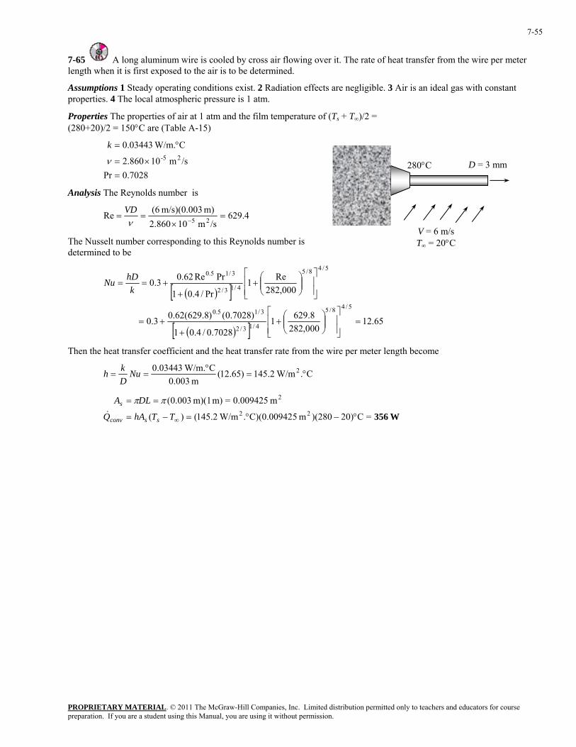
PROPRIETARY MATERIAL. © 2011 The McGraw-Hill Companies, Inc. Limited distribution permitted only to teachers and educators for course preparation. If you are a student using this Manual, you are using it without permission.
7-55
7-65 A long aluminum wire is cooled by cross air flowing over it. The rate of heat transfer from the wire per meter length when it is first exposed to the air is to be determined.
Assumptions 1 Steady operating conditions exist. 2 Radiation effects are negligible. 3 Air is an ideal gas with constant properties. 4 The local atmospheric pressure is 1 atm.
Properties The properties of air at 1 atm and the film temperature of (Ts + T∞)/2 = (280+20)/2 = 150°C are (Table A-15)
7028.0Pr
/sm 10860.2
C W/m.03443.025-
=×=
°=
ν
k
D = 3 mm 280°C Analysis The Reynolds number is
4.629/sm 10860.2
m) m/s)(0.003 (6Re 25 =×
==−ν
VD
V = 6 m/s T∞ = 20°C The Nusselt number corresponding to this Reynolds number is
determined to be
( )[ ]
( )[ ] 65.12000,282
8.62917028.0/4.01
)7028.0()8.629(62.03.0
000,282Re1
Pr/4.01
PrRe62.03.0
5/48/5
4/13/2
3/15.0
5/48/5
4/13/2
3/15.0
=⎥⎥⎦
⎤
⎢⎢⎣
⎡⎟⎟⎠
⎞⎜⎜⎝
⎛+
++=
⎥⎥⎦
⎤
⎢⎢⎣
⎡⎟⎟⎠
⎞⎜⎜⎝
⎛+
++==
khDNu
Then the heat transfer coefficient and the heat transfer rate from the wire per meter length become
C. W/m2.145)65.12(m 003.0
C W/m.03443.0 2 °=°
== NuDkh
W356=C0)2)(280m 5C)(0.00942. W/m2.145()(
m 0.009425=m) m)(1 003.0(22
2
°−°=−=
==
∞TThAQ
DLA
ssconv
s
&
ππ
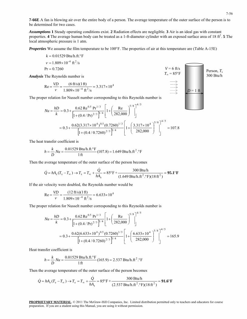
PROPRIETARY MATERIAL. © 2011 The McGraw-Hill Companies, Inc. Limited distribution permitted only to teachers and educators for course preparation. If you are a student using this Manual, you are using it without permission.
7-56
7-66E A fan is blowing air over the entire body of a person. The average temperature of the outer surface of the person is to be determined for two cases.
Assumptions 1 Steady operating conditions exist. 2 Radiation effects are negligible. 3 Air is an ideal gas with constant properties. 4 The average human body can be treated as a 1-ft-diameter cylinder with an exposed surface area of 18 ft2. 5 The local atmospheric pressure is 1 atm.
Properties We assume the film temperature to be 100°F. The properties of air at this temperature are (Table A-15E)
7260.0Pr
/sft 10809.1
FBtu/h.ft. 01529.024-
=×=
°=
ν
k
D = 1 ft
V = 6 ft/s T∞ = 85°F
Person, Ts300 Btu/h Analysis The Reynolds number is
424
10317.3/sft 10809.1
ft) ft/s)(1 (6Re ×=
×==
−νVD
The proper relation for Nusselt number corresponding to this Reynolds number is
[ ]
[ ]8.107
000,28210317.31
)7260.0/4.0(1
)7260.0()10317.3(62.03.0
000,282Re1
Pr)/4.0(1
PrRe62.03.0
5/48/54
4/13/2
3/15.04
5/48/5
4/13/2
3/15.0
=⎥⎥
⎦
⎤
⎢⎢
⎣
⎡
⎟⎟⎠
⎞⎜⎜⎝
⎛ ×+
+
×+=
⎥⎥⎦
⎤
⎢⎢⎣
⎡⎟⎟⎠
⎞⎜⎜⎝
⎛+
++==
khDNu
The heat transfer coefficient is
F.Btu/h.ft 649.1)8.107(ft 1
FBtu/h.ft. 01529.0 2 °=°
== NuDkh
Then the average temperature of the outer surface of the person becomes
F95.1°=°
°=+=→−= ∞∞)ft F)(18.Btu/h.ft 649.1(
Btu/h 300+F85)(22
ssss hA
QTTTThAQ&
&
If the air velocity were doubled, the Reynolds number would be
424
10633.6/sft 10809.1
ft) ft/s)(1 (12Re ×=
×==
−νVD
The proper relation for Nusselt number corresponding to this Reynolds number is
[ ]
[ ]9.165
000,28210633.61
)7260.0/4.0(1
)7260.0()10633.6(62.03.0
000,282Re1
Pr)/4.0(1
PrRe62.03.0
5/48/54
4/13/2
3/15.04
5/48/5
4/13/2
3/15.0
=⎥⎥
⎦
⎤
⎢⎢
⎣
⎡
⎟⎟⎠
⎞⎜⎜⎝
⎛ ×+
+
×+=
⎥⎥⎦
⎤
⎢⎢⎣
⎡⎟⎟⎠
⎞⎜⎜⎝
⎛+
++==
khDNu
Heat transfer coefficient is
F.Btu/h.ft 537.2)9.165(ft 1
FBtu/h.ft. 01529.0 2 °=°
== NuDkh
Then the average temperature of the outer surface of the person becomes
F91.6°=°
°=+=→−= ∞∞)ft F)(18.Btu/h.ft 537.2(
Btu/h 300+F85)(22
ssss hA
QTTTThAQ&
&
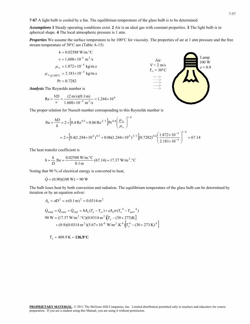
PROPRIETARY MATERIAL. © 2011 The McGraw-Hill Companies, Inc. Limited distribution permitted only to teachers and educators for course preparation. If you are a student using this Manual, you are using it without permission.
7-57
7-67 A light bulb is cooled by a fan. The equilibrium temperature of the glass bulb is to be determined.
Assumptions 1 Steady operating conditions exist. 2 Air is an ideal gas with constant properties. 3 The light bulb is in spherical shape. 4 The local atmospheric pressure is 1 atm.
Properties We assume the surface temperature to be 100°C for viscosity. The properties of air at 1 atm pressure and the free stream temperature of 30°C are (Table A-15)
7282.0Pr
kg/m.s 10181.2
kg/m.s 10872.1
/sm 10608.1
C W/m.02588.0
5C100@,
5
25-
=
×=
×=
×=
°=
−°
−∞
s
k
µ
µ
ν Lamp 100 W ε = 0.9
Air V = 2 m/s T∞ = 30°C
Analysis The Reynolds number is
425
10244.1/sm 10608.1
m) m/s)(0.1 (2Re ×=
×==
−νVD
The proper relation for Nusselt number corresponding to this Reynolds number is
[ ]
[ ] 14.6710181.210872.1)7282.0()10244.1(06.0)10244.1(4.02
PrRe06.0Re4.02
4/1
5
54.03/245.04
4/14.03/25.0
=⎟⎟⎠
⎞⎜⎜⎝
⎛
×
××+×+=
⎟⎟⎠
⎞⎜⎜⎝
⎛++==
−
−
∞
skhDNu
µµ
The heat transfer coefficient is
C. W/m37.17)14.67(m 1.0
C W/m.02588.0 2 °=°
== NuDkh
Noting that 90 % of electrical energy is converted to heat,
W90= W)100)(90.0(=Q&
The bulb loses heat by both convection and radiation. The equilibrium temperature of the glass bulb can be determined by iteration or by an equation solver:
222 m 0314.0)m 1.0( === ππDAs
[ ][ ]
C136.9°==
+−×+
+−°=
−+−=+= ∞
K 9.409
)K 27330().K W/m10)(5.67m (0.0314)9.0(
K)27330()m C)(0.0314. W/m37.17( W90
)()(
44428-2
22
44total
s
s
s
surrssssradconv
T
T
T
TTATThAQQQ σε&&&
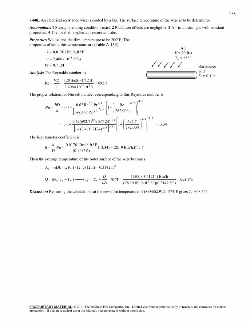
PROPRIETARY MATERIAL. © 2011 The McGraw-Hill Companies, Inc. Limited distribution permitted only to teachers and educators for course preparation. If you are a student using this Manual, you are using it without permission.
7-58
7-68E An electrical resistance wire is cooled by a fan. The surface temperature of the wire is to be determined.
Assumptions 1 Steady operating conditions exist. 2 Radiation effects are negligible. 3 Air is an ideal gas with constant properties. 4 The local atmospheric pressure is 1 atm.
Properties We assume the film temperature to be 200°F. The properties of air at this temperature are (Table A-15E)
Air V = 20 ft/s T∞ = 85°F
7124.0Pr/sft 10406.2
FBtu/h.ft. 01761.024-
=×=
°=
ν
k
Resistance wire D = 0.1 in
Analysis The Reynolds number is
7.692/sft 10406.2
ft) 12ft/s)(0.1/ (20Re
24=
×==
−νVD
The proper relation for Nusselt number corresponding to this Reynolds number is
[ ]
[ ]34.13
000,2827.6921
)7124.0/4.0(1
)7124.0()7.692(62.03.0
000,282Re1
Pr)/4.0(1
PrRe62.03.0
5/48/5
4/13/2
3/15.0
5/48/5
4/13/2
3/15.0
=⎥⎥⎦
⎤
⎢⎢⎣
⎡⎟⎟⎠
⎞⎜⎜⎝
⎛+
++=
⎥⎥⎦
⎤
⎢⎢⎣
⎡⎟⎟⎠
⎞⎜⎜⎝
⎛+
++==
khDNu
The heat transfer coefficient is
F.Btu/h.ft 19.28)34.13(ft) 12/1.0(
FBtu/h.ft. 01761.0 2 °=°
== NuDkh
Then the average temperature of the outer surface of the wire becomes
2ft 3142.0ft) 12)(ft 12/1.0( === ππDLAs
F662.9°=°
×°=+=⎯→⎯−= ∞∞
)ft F)(0.3142.Btu/h.ft 19.28(Btu/h 3.41214)(1500+F85)(
22hAQTTTThAQ sss
&&
Discussion Repeating the calculations at the new film temperature of (85+662.9)/2=374°F gives Ts=668.3°F.
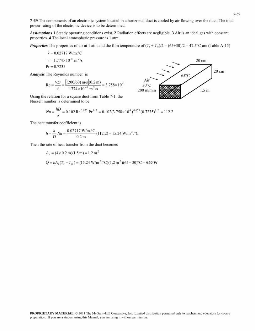
PROPRIETARY MATERIAL. © 2011 The McGraw-Hill Companies, Inc. Limited distribution permitted only to teachers and educators for course preparation. If you are a student using this Manual, you are using it without permission.
7-59
7-69 The components of an electronic system located in a horizontal duct is cooled by air flowing over the duct. The total power rating of the electronic device is to be determined.
Assumptions 1 Steady operating conditions exist. 2 Radiation effects are negligible. 3 Air is an ideal gas with constant properties. 4 The local atmospheric pressure is 1 atm.
Properties The properties of air at 1 atm and the film temperature of (Ts + T∞)/2 = (65+30)/2 = 47.5°C are (Table A-15)
7235.0Pr
/sm 10774.1
C W/m.02717.025-
=×=
°=
ν
k
1.5 m
65°C Air
30°C 200 m/min
20 cm
20 cmAnalysis The Reynolds number is
[ ] 4
2510758.3
/sm 10774.1m) (0.2m/s (200/60)
Re ×=×
==−ν
VD
Using the relation for a square duct from Table 7-1, the Nusselt number is determined to be
2.112)7235.0()10758.3(102.0PrRe102.0 3/1675.043/1675.0 =×===k
hDNu
The heat transfer coefficient is
C. W/m24.15)2.112(m 2.0
C W/m.02717.0 2 °=°
== NuDkh
Then the rate of heat transfer from the duct becomes
2m 2.1m) 5.1)(m 2.04( =×=sA
W640=C30))(65m C)(1.2. W/m24.15()( 22 °−°=−= ∞TThAQ ss&
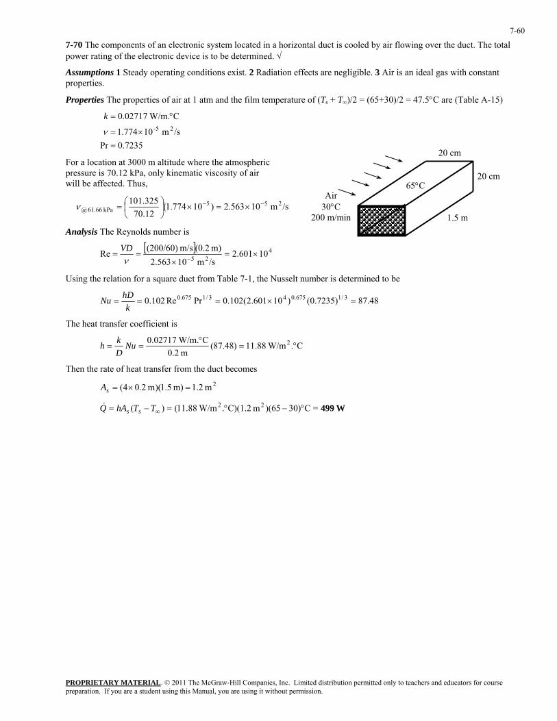
PROPRIETARY MATERIAL. © 2011 The McGraw-Hill Companies, Inc. Limited distribution permitted only to teachers and educators for course preparation. If you are a student using this Manual, you are using it without permission.
7-60
7-70 The components of an electronic system located in a horizontal duct is cooled by air flowing over the duct. The total power rating of the electronic device is to be determined. √
Assumptions 1 Steady operating conditions exist. 2 Radiation effects are negligible. 3 Air is an ideal gas with constant properties.
Properties The properties of air at 1 atm and the film temperature of (Ts + T∞)/2 = (65+30)/2 = 47.5°C are (Table A-15)
7235.0Pr
/sm 10774.1
C W/m.02717.025-
=×=
°=
ν
k
1.5 m
65°C Air
30°C 200 m/min
20 cmFor a location at 3000 m altitude where the atmospheric pressure is 70.12 kPa, only kinematic viscosity of air will be affected. Thus,
20 cm
/sm 10563.2)10774.1(12.70325.101 255
kPa 66.61@−− ×=×⎟
⎠⎞
⎜⎝⎛=ν
Analysis The Reynolds number is
[ ] 425 10601.2/sm 10563.2m) (0.2m/s (200/60)Re ×=
×==
−νVD
Using the relation for a square duct from Table 7-1, the Nusselt number is determined to be
48.87)7235.0()10601.2(102.0PrRe102.0 3/1675.043/1675.0 =×===k
hDNu
The heat transfer coefficient is
C. W/m88.11)48.87(m 2.0
C W/m.02717.0 2 °=°
== NuDkh
Then the rate of heat transfer from the duct becomes
2m 2.1m) 5.1)(m 2.04( =×=sA
W499=C30))(65m C)(1.2. W/m88.11()( 22 °−°=−= ∞TThAQ ss&
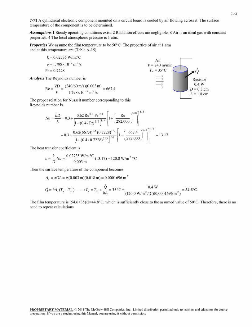
PROPRIETARY MATERIAL. © 2011 The McGraw-Hill Companies, Inc. Limited distribution permitted only to teachers and educators for course preparation. If you are a student using this Manual, you are using it without permission.
7-61
7-71 A cylindrical electronic component mounted on a circuit board is cooled by air flowing across it. The surface temperature of the component is to be determined.
Assumptions 1 Steady operating conditions exist. 2 Radiation effects are negligible. 3 Air is an ideal gas with constant properties. 4 The local atmospheric pressure is 1 atm.
Properties We assume the film temperature to be 50°C. The properties of air at 1 atm and at this temperature are (Table A-15)
7228.0Pr
/sm 10798.1
C W/m.02735.025-
=×=
°=
ν
k
Q&
Resistor 0.4 W
D = 0.3 cm L = 1.8 cm
Air V = 240 m/minT∞ = 35°C
Analysis The Reynolds number is
4.667/sm 10798.1
m) m/s)(0.003 (240/60Re
25=
×==
−νVD
The proper relation for Nusselt number corresponding to this Reynolds number is
[ ]
[ ]17.13
000,2824.6671
)7228.0/4.0(1
)7228.0()4.667(62.03.0
000,282Re1
Pr)/4.0(1
PrRe62.03.0
5/48/5
4/13/2
3/15.0
5/48/5
4/13/2
3/15.0
=⎥⎥⎦
⎤
⎢⎢⎣
⎡⎟⎟⎠
⎞⎜⎜⎝
⎛+
++=
⎥⎥⎦
⎤
⎢⎢⎣
⎡⎟⎟⎠
⎞⎜⎜⎝
⎛+
++==
khDNu
The heat transfer coefficient is
C. W/m0.120)17.13(m 003.0
C W/m.02735.0 2 °=°
== NuDkh
Then the surface temperature of the component becomes
2m 0001696.0m) 018.0)(m 003.0( === ππDLAs
C54.6°=°
°=+=⎯→⎯−= ∞∞)m 96C)(0.00016. W/m0.120(
W0.4+C 35)(22hA
QTTTThAQ sss
&&
The film temperature is (54.6+35)/2=44.8°C, which is sufficiently close to the assumed value of 50°C. Therefore, there is no need to repeat calculations.
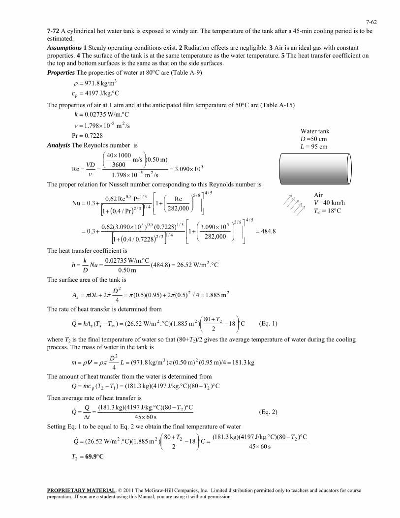
PROPRIETARY MATERIAL. © 2011 The McGraw-Hill Companies, Inc. Limited distribution permitted only to teachers and educators for course preparation. If you are a student using this Manual, you are using it without permission.
7-62
7-72 A cylindrical hot water tank is exposed to windy air. The temperature of the tank after a 45-min cooling period is to be estimated. Assumptions 1 Steady operating conditions exist. 2 Radiation effects are negligible. 3 Air is an ideal gas with constant properties. 4 The surface of the tank is at the same temperature as the water temperature. 5 The heat transfer coefficient on the top and bottom surfaces is the same as that on the side surfaces. Properties The properties of water at 80°C are (Table A-9)
CJ/kg. 4197
kg/m 8.971 3
°==
pcρ
The properties of air at 1 atm and at the anticipated film temperature of 50°C are (Table A-15)
7228.0Pr
/sm 10798.1
C W/m.02735.025-
=×=
°=
ν
k
Water tankD =50 cm L = 95 cm Analysis The Reynolds number is
525
10090.3/sm 10798.1
m) (0.50m/s 3600
100040
Re ×=×
⎟⎠⎞
⎜⎝⎛ ×
==−ν
VD
The proper relation for Nusselt number corresponding to this Reynolds number is
( )[ ]
( )[ ] 8.484000,282
10090.317228.0/4.01
)7228.0()10090.3(62.03.0
000,282Re1
Pr/4.01
PrRe62.03.0Nu
5/48/55
4/13/2
3/15.05
5/48/5
4/13/2
3/15.0
=⎥⎥
⎦
⎤
⎢⎢
⎣
⎡
⎟⎟⎠
⎞⎜⎜⎝
⎛ ×+
+
×+=
⎥⎥⎦
⎤
⎢⎢⎣
⎡⎟⎟⎠
⎞⎜⎜⎝
⎛+
++=
Air V =40 km/h T∞ = 18°C
The heat transfer coefficient is
C. W/m.5226)8.484(m 50.0
C W/m.02735.0 2 °=°
== NuDkh
The surface area of the tank is
222
m 885.14/)5.0(2)95.0)(5.0(4
2 =+=+= ππππ DDLAs
The rate of heat transfer is determined from
C182
80)m C)(1.885. W/m52.26()( 222 °⎟⎟
⎠
⎞⎜⎜⎝
⎛−
+°=−= ∞
TTThAQ ss
& (Eq. 1)
where T2 is the final temperature of water so that (80+T2)/2 gives the average temperature of water during the cooling process. The mass of water in the tank is
kg 3.181m)/4 (0.95m) (0.50)kg/m 8.971(4
232
==== πρπρ LDm V
The amount of heat transfer from the water is determined from C)C)(80J/kg. kg)(4197 3.181()( 212 °−°=−= TTTmcQ p
Then average rate of heat transfer is
s 6045
C)C)(80J/kg. kg)(4197 3.181( 2
×°−°
=∆
=T
tQQ& (Eq. 2)
Setting Eq. 1 to be equal to Eq. 2 we obtain the final temperature of water
C69.9°=
×°−°
=°⎟⎟⎠
⎞⎜⎜⎝
⎛−
+°=
2
2222
s 6045C)C)(80J/kg. kg)(4197 3.181(
C182
80)m C)(1.885. W/m52.26(
T
TTQ&
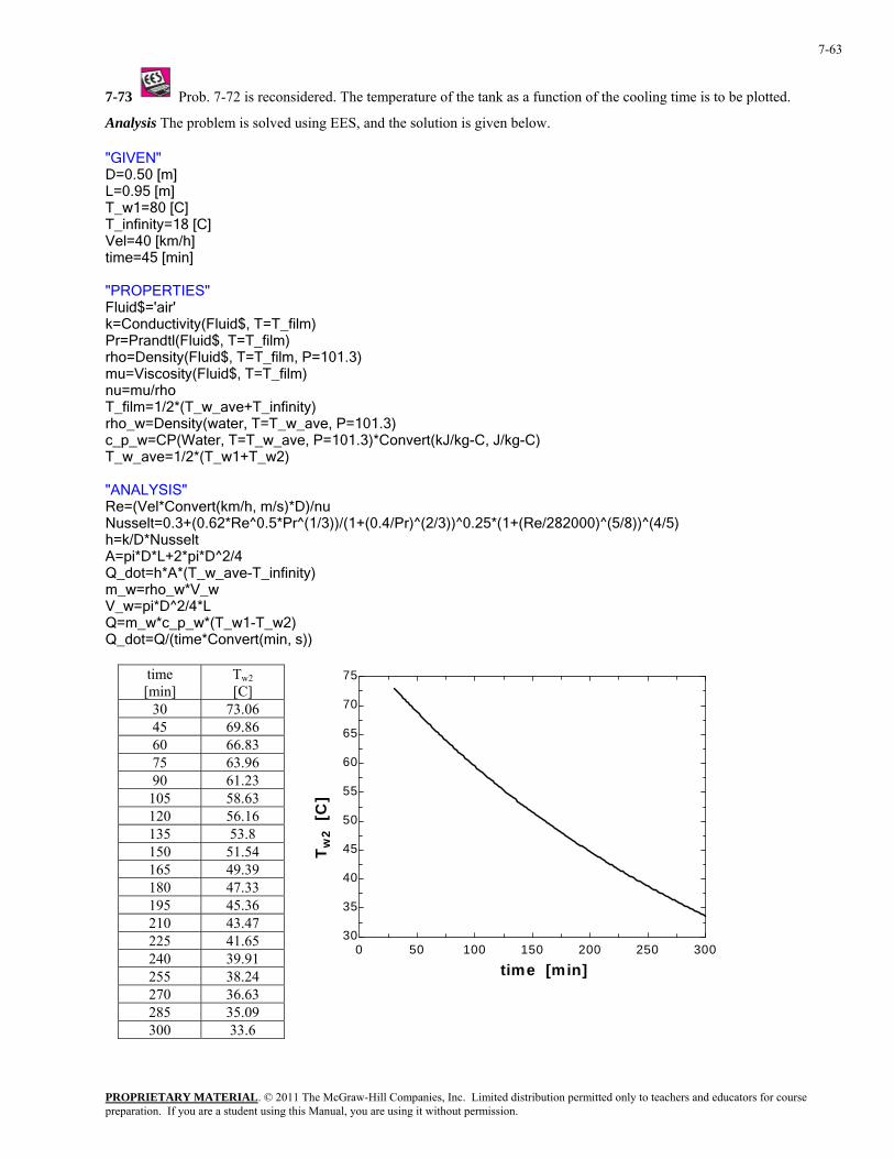
PROPRIETARY MATERIAL. © 2011 The McGraw-Hill Companies, Inc. Limited distribution permitted only to teachers and educators for course preparation. If you are a student using this Manual, you are using it without permission.
7-63
7-73 Prob. 7-72 is reconsidered. The temperature of the tank as a function of the cooling time is to be plotted.
Analysis The problem is solved using EES, and the solution is given below.
"GIVEN" D=0.50 [m] L=0.95 [m] T_w1=80 [C] T_infinity=18 [C] Vel=40 [km/h] time=45 [min] "PROPERTIES" Fluid$='air' k=Conductivity(Fluid$, T=T_film) Pr=Prandtl(Fluid$, T=T_film) rho=Density(Fluid$, T=T_film, P=101.3) mu=Viscosity(Fluid$, T=T_film) nu=mu/rho T_film=1/2*(T_w_ave+T_infinity) rho_w=Density(water, T=T_w_ave, P=101.3) c_p_w=CP(Water, T=T_w_ave, P=101.3)*Convert(kJ/kg-C, J/kg-C) T_w_ave=1/2*(T_w1+T_w2) "ANALYSIS" Re=(Vel*Convert(km/h, m/s)*D)/nu Nusselt=0.3+(0.62*Re^0.5*Pr^(1/3))/(1+(0.4/Pr)^(2/3))^0.25*(1+(Re/282000)^(5/8))^(4/5) h=k/D*Nusselt A=pi*D*L+2*pi*D^2/4 Q_dot=h*A*(T_w_ave-T_infinity) m_w=rho_w*V_w V_w=pi*D^2/4*L Q=m_w*c_p_w*(T_w1-T_w2) Q_dot=Q/(time*Convert(min, s))
time [min]
Tw2 [C]
30 73.06 45 69.86 60 66.83 75 63.96 90 61.23
105 58.63 120 56.16 135 53.8 150 51.54 165 49.39 180 47.33 195 45.36 210 43.47 225 41.65 240 39.91 255 38.24 270 36.63 285 35.09 300 33.6
0 50 100 150 200 250 30030
35
40
45
50
55
60
65
70
75
time [min]
T w2
[C]

PROPRIETARY MATERIAL. © 2011 The McGraw-Hill Companies, Inc. Limited distribution permitted only to teachers and educators for course preparation. If you are a student using this Manual, you are using it without permission.
7-64
7-74 Air flows over a spherical tank containing iced water. The rate of heat transfer to the tank and the rate at which ice melts are to be determined.
Assumptions 1 Steady operating conditions exist. 2 Radiation effects are negligible. 3 Air is an ideal gas with constant properties. 4 The local atmospheric pressure is 1 atm.
Properties The properties of air at 1 atm pressure and the free stream temperature of 25°C are (Table A-15)
7296.0Pr
kg/m.s 10729.1
kg/m.s 10849.1
/sm 10562.1
C W/m.02551.0
5C0@,
5
25-
=
×=
×=
×=
°=
−°
−∞
s
k
µ
µ
ν Air V = 6 m/s T∞ =25°C
D =2.2 m
Iced water
Analysis The Reynolds number is
525 10451.8/sm 10562.1
m) m/s)(2.2 (6Re ×=×
==−ν
VD
The proper relation for Nusselt number corresponding to this Reynolds number is
[ ]
[ ] 0.81210729.110849.1)7296.0()10451.8(06.0)10451.8(4.02
PrRe06.0Re4.02
4/1
5
54.03/255.05
4/14.03/25.0
=⎟⎟⎠
⎞⎜⎜⎝
⎛
×
××+×+=
⎟⎟⎠
⎞⎜⎜⎝
⎛++==
−
−
∞
skhDNu
µµ
The heat transfer coefficient is
C. W/m.4159)0.812(m 2.2
C W/m.02551.0 2 °=°
== NuDkh
Then the rate of heat transfer is determined to be
W3580=°−°=−=
==
∞ C)025)(m C)(15.21. W/m415.9()(
m 15.21=m) 2.2(22
222
TThAQ
DA
ss
s
&
ππ
The rate at which ice melts is
kg/min 0.644====⎯→⎯= kg/s 01073.0kJ/kg 7.333kW 580.3
fgfg h
QmhmQ&
&&&
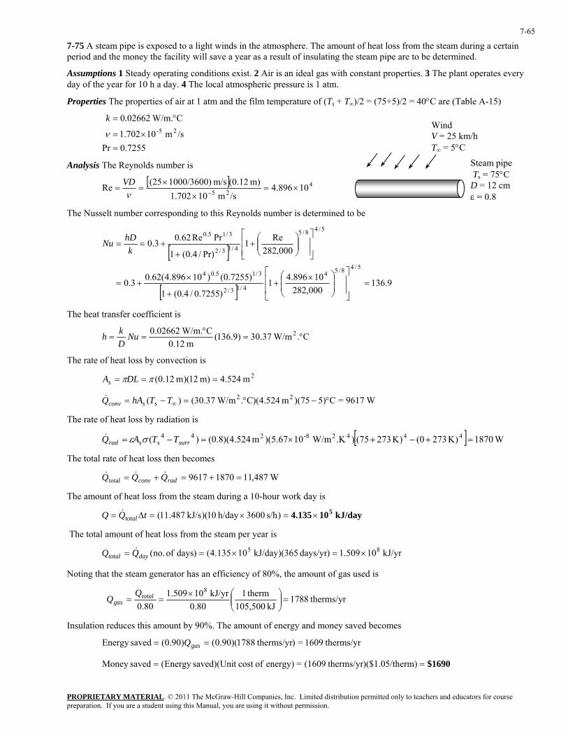
PROPRIETARY MATERIAL. © 2011 The McGraw-Hill Companies, Inc. Limited distribution permitted only to teachers and educators for course preparation. If you are a student using this Manual, you are using it without permission.
7-65
7-75 A steam pipe is exposed to a light winds in the atmosphere. The amount of heat loss from the steam during a certain period and the money the facility will save a year as a result of insulating the steam pipe are to be determined.
Assumptions 1 Steady operating conditions exist. 2 Air is an ideal gas with constant properties. 3 The plant operates every day of the year for 10 h a day. 4 The local atmospheric pressure is 1 atm.
Properties The properties of air at 1 atm and the film temperature of (Ts + T∞)/2 = (75+5)/2 = 40°C are (Table A-15)
7255.0Pr
/sm 10702.1
C W/m.02662.025-
=×=
°=
ν
kWind V = 25 km/hT∞ = 5°C
Steam p T
ipe °Cs = 75
D = 12 cmε = 0.8
Analysis The Reynolds number is
[ ] 425 10896.4/sm 10702.1
m) (0.12m/s 1000/3600)(25Re ×=×
×==
−νVD
The Nusselt number corresponding to this Reynolds number is determined to be
[ ]
[ ] 9.136000,282
10896.41)7255.0/4.0(1
)7255.0()10896.4(62.03.0
000,282Re1
Pr)/4.0(1
PrRe62.03.0
5/48/54
4/13/2
3/15.04
5/48/5
4/13/2
3/15.0
=⎥⎥
⎦
⎤
⎢⎢
⎣
⎡
⎟⎟⎠
⎞⎜⎜⎝
⎛ ×+
+
×+=
⎥⎥⎦
⎤
⎢⎢⎣
⎡⎟⎟⎠
⎞⎜⎜⎝
⎛+
++==
khDNu
The heat transfer coefficient is
C. W/m37.30)9.136(m 12.0
C W/m.02662.0 2 °=°
== NuDkh
The rate of heat loss by convection is
2m 524.4m) 12)(m 12.0( === ππDLAs
W9617=C5))(75m C)(4.524. W/m37.30()( 22 °−°=−= ∞TThAQ ssconv&
The rate of heat loss by radiation is
[ ] W1870)K 2730()K 27375().K W/m10)(5.67m (4.524)8.0()( 4442-8244 =+−+×=−= surrssrad TTAQ σε&
The total rate of heat loss then becomes
W487,1118709617total =+=+= radconv QQQ &&&
The amount of heat loss from the steam during a 10-hour work day is
kJ/day 104.135 5×=×=∆= )s/h 3600h/day 10)(kJ/s 487.11(tQQ total&
The total amount of heat loss from the steam per year is
kJ/yr 10509.1)days/yr 365)(kJ/day 10135.4()days of no.( 85 ×=×== daytotal QQ &
Noting that the steam generator has an efficiency of 80%, the amount of gas used is
therms/yr1788kJ 105,500
therm180.0
kJ/yr 10509.180.0
8=⎟⎟
⎠
⎞⎜⎜⎝
⎛×== total
gasQ
Q
Insulation reduces this amount by 90%. The amount of energy and money saved becomes
therms/yr1609=) therms/yr1788)(90.0()90.0(savedEnergy == gasQ
$1690== erm))($1.05/th therms/yr(1609=energy) ofcost t saved)(UniEnergy (savedMoney
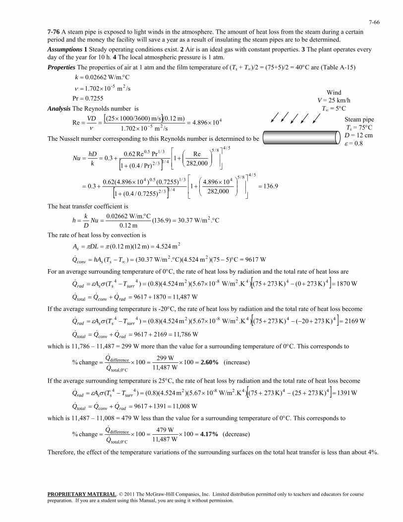
PROPRIETARY MATERIAL. © 2011 The McGraw-Hill Companies, Inc. Limited distribution permitted only to teachers and educators for course preparation. If you are a student using this Manual, you are using it without permission.
7-66
7-76 A steam pipe is exposed to light winds in the atmosphere. The amount of heat loss from the steam during a certain period and the money the facility will save a year as a result of insulating the steam pipes are to be determined. Assumptions 1 Steady operating conditions exist. 2 Air is an ideal gas with constant properties. 3 The plant operates every day of the year for 10 h. 4 The local atmospheric pressure is 1 atm. Properties The properties of air at 1 atm and the film temperature of (Ts + T∞)/2 = (75+5)/2 = 40°C are (Table A-15)
7255.0Pr
/sm 10702.1
C W/m.02662.025-
=×=
°=
ν
k
Analysis The Reynolds number is
[ ] 425 10896.4/sm 10702.1
m) (0.12m/s 1000/3600)(25Re ×=×
×==
−νVD
The Nusselt number corresponding to this Reynolds number is determined to be
[ ]
[ ] 9.136000,282
10896.41)7255.0/4.0(1
)7255.0()10896.4(62.03.0
000,282Re1
Pr)/4.0(1
PrRe62.03.0
5/48/54
4/13/2
3/15.04
5/48/5
4/13/2
3/15.0
=⎥⎥
⎦
⎤
⎢⎢
⎣
⎡
⎟⎟⎠
⎞⎜⎜⎝
⎛ ×+
+
×+=
⎥⎥⎦
⎤
⎢⎢⎣
⎡⎟⎟⎠
⎞⎜⎜⎝
⎛+
++==
khDNu
Wind V = 25 km/h
T∞ = 5°C
Steam p T
ipe 5°Cs = 7
D = 12 cmε = 0.8
The heat transfer coefficient is
C. W/m37.30)9.136(m 12.0
C W/m.02662.0 2 °=°
== NuDkh
The rate of heat loss by convection is
2m 524.4m) 12)(m 12.0( === ππDLAs
W9617=C5))(75m C)(4.524. W/m37.30()( 22 °−°=−= ∞TThAQ ssconv&
For an average surrounding temperature of 0°C, the rate of heat loss by radiation and the total rate of heat loss are
[ ] W1870)K 2730()K 27375().K W/m10)(5.67m (4.524)8.0()( 4442-8244 =+−+×=−= surrssrad TTAQ σε&
W487,1118709617total =+=+= radconv QQQ &&&
If the average surrounding temperature is -20°C, the rate of heat loss by radiation and the total rate of heat loss become
[ ] W2169)K 27320()K 27375().K W/m10)(5.67m (4.524)8.0()( 4442-8244 =+−−+×=−= surrssrad TTAQ σε&
W786,1121699617 =+=+= radconvtotal QQQ &&&
which is 11,786 – 11,487 = 299 W more than the value for a surrounding temperature of 0°C. This corresponds to
2.60%=×=×=°
100 W487,11
W299100change %Ctotal,0
difference
QQ&
& (increase)
If the average surrounding temperature is 25°C, the rate of heat loss by radiation and the total rate of heat loss become
[ ] W1391)K 27325()K 27375().K W/m10)(5.67m (4.524)8.0()( 4442-8244 =+−+×=−= surrssrad TTAQ σε&
W008,1113919617 =+=+= radconvtotal QQQ &&&
which is 11,487 – 11,008 = 479 W less than the value for a surrounding temperature of 0°C. This corresponds to
4.17%=×=×=°
100 W487,11
W479100change %Ctotal,0
difference
QQ&
& (decrease)
Therefore, the effect of the temperature variations of the surrounding surfaces on the total heat transfer is less than about 4%.
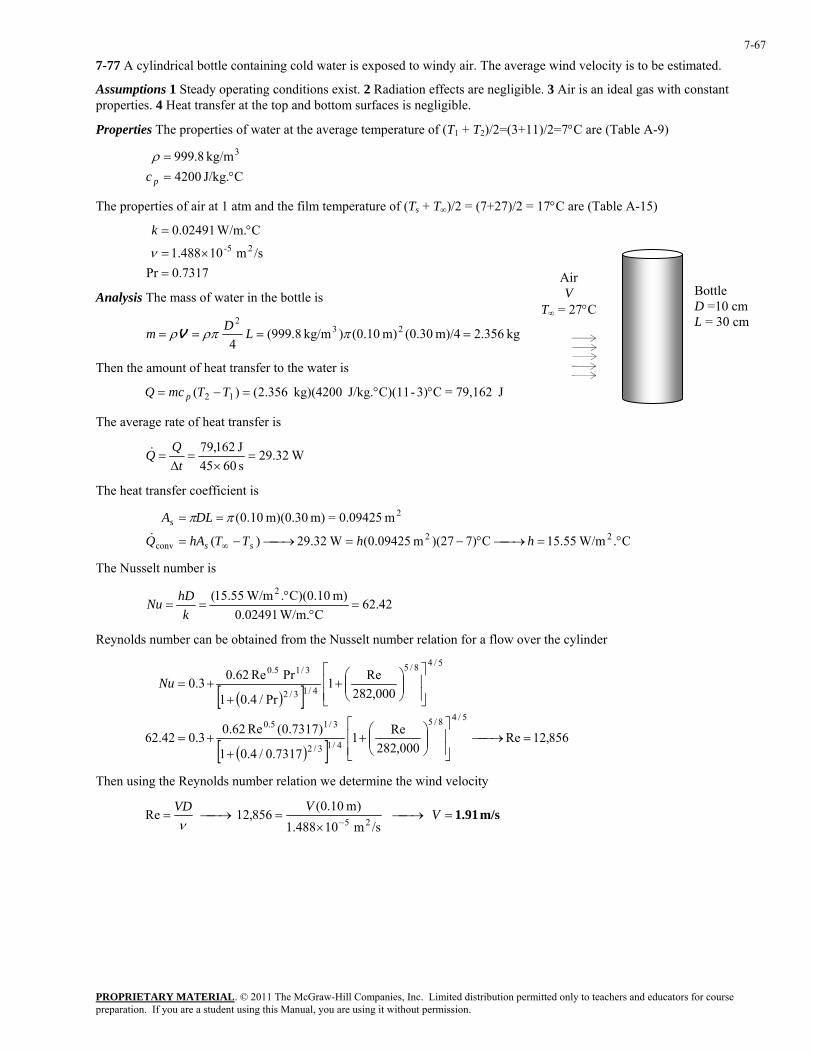
PROPRIETARY MATERIAL. © 2011 The McGraw-Hill Companies, Inc. Limited distribution permitted only to teachers and educators for course preparation. If you are a student using this Manual, you are using it without permission.
7-67
7-77 A cylindrical bottle containing cold water is exposed to windy air. The average wind velocity is to be estimated.
Assumptions 1 Steady operating conditions exist. 2 Radiation effects are negligible. 3 Air is an ideal gas with constant properties. 4 Heat transfer at the top and bottom surfaces is negligible.
Properties The properties of water at the average temperature of (T1 + T2)/2=(3+11)/2=7°C are (Table A-9)
CJ/kg. 4200
kg/m 8.999 3
°==
pcρ
The properties of air at 1 atm and the film temperature of (Ts + T∞)/2 = (7+27)/2 = 17°C are (Table A-15)
7317.0Pr
/sm 10488.1
C W/m.02491.025-
=×=
°=
ν
k
Analysis The mass of water in the bottle is
kg 2.356m)/4 (0.30m) (0.10)kg/m 8.999(4
232
==== πρπρ LDm V
Then the amount of heat transfer to the water is
J 79,162=C3)-C)(11J/kg. kg)(4200 356.2()( 12 °°=−= TTmcQ p
Air V
T∞ = 27°C Bottle D =10 cm L = 30 cm
The average rate of heat transfer is
W32.29s 6045J 162,79=
×=
∆=
tQQ&
The heat transfer coefficient is
C. W/m55.15C7))(27m (0.09425 W32.29)(
m 0.09425=m) m)(0.30 10.0(22
conv
2
°=⎯→⎯°−=⎯→⎯−=
==
∞ hhTThAQ
DLA
ss
s
&
ππ
The Nusselt number is
42.62C W/m.0.02491
m) C)(0.10. W/m55.15( 2=
°°
==k
hDNu
Reynolds number can be obtained from the Nusselt number relation for a flow over the cylinder
( )[ ]
( )[ ] 856,12Re000,282
Re17317.0/4.01
)7317.0(Re62.03.042.62
000,282Re1
Pr/4.01
PrRe62.03.0
5/48/5
4/13/2
3/15.0
5/48/5
4/13/2
3/15.0
=⎯→⎯⎥⎥⎦
⎤
⎢⎢⎣
⎡⎟⎟⎠
⎞⎜⎜⎝
⎛+
++=
⎥⎥⎦
⎤
⎢⎢⎣
⎡⎟⎟⎠
⎞⎜⎜⎝
⎛+
++=Nu
Then using the Reynolds number relation we determine the wind velocity
m/s 1.91=⎯→⎯×
=⎯→⎯=−
VVVD
/sm 10488.1)m 10.0(
856,12 Re25ν
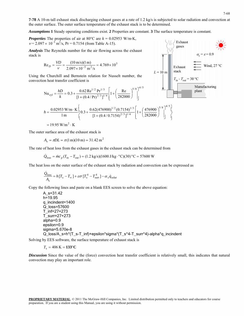
PROPRIETARY MATERIAL. © 2011 The McGraw-Hill Companies, Inc. Limited distribution permitted only to teachers and educators for course preparation. If you are a student using this Manual, you are using it without permission.
7-68
7-78 A 10-m tall exhaust stack discharging exhaust gases at a rate of 1.2 kg/s is subjected to solar radiation and convection at the outer surface. The outer surface temperature of the exhaust stack is to be determined.
Assumptions 1 Steady operating conditions exist. 2 Properties are constant. 3 The surface temperature is constant.
Properties The properties of air at 80°C are k = 0.02953 W/m·K, ν = 2.097 × 10⁻⁵ m2/s, Pr = 0.7154 (from Table A-15).
Analysis The Reynolds number for the air flowing across the exhaust stack is
525 10769.4/sm 10097.2
)m 1)(m/s 10(Re ×=×
==−ν
VDD
Using the Churchill and Bernstein relation for Nusselt number, the convection heat transfer coefficient is
5/48/5
4/13/2
3/12/1
cyl 282000Re1
]Pr)/4.0(1[PrRe62.03.0Nu
⎥⎥⎦
⎤
⎢⎢⎣
⎡⎟⎠⎞
⎜⎝⎛+
++==
khD
K W/m95.19
2820004769001
])7154.0/4.0(1[)7154.0()476900(62.03.0
m 1K W/m02953.0
2
5/48/5
4/13/2
3/12/1
⋅=
⎪⎭
⎪⎬⎫
⎪⎩
⎪⎨⎧
⎥⎥⎦
⎤
⎢⎢⎣
⎡⎟⎠⎞
⎜⎝⎛+
++
⋅=h
The outer surface area of the exhaust stack is
2m 42.31)m 10)(m 1( === ππDLAs
The rate of heat loss from the exhaust gases in the exhaust stack can be determined from
W57600C )30(C)J/kg 1600)(kg/s 2.1()( outinloss =°°⋅=−= TTcmQ p&&
The heat loss on the outer surface of the exhaust stack by radiation and convection can be expressed as
solar4
surr4loss ][ ][ qTTTTh
AQ
ssss
&&
αεσ −−+−= ∞
Copy the following lines and paste on a blank EES screen to solve the above equation: A_s=31.42 h=19.95 q_incindent=1400 Q_loss=57600 T_inf=27+273 T_surr=27+273 alpha=0.9 epsilon=0.9 sigma=5.670e-8 Q_loss/A_s=h*(T_s-T_inf)+epsilon*sigma*(T_s^4-T_surr^4)-alpha*q_incindent
Solving by EES software, the surface temperature of exhaust stack is
C133°== K 406sT
Discussion Since the value of the (force) convection heat transfer coefficient is relatively small, this indicates that natural convection may play an important role.
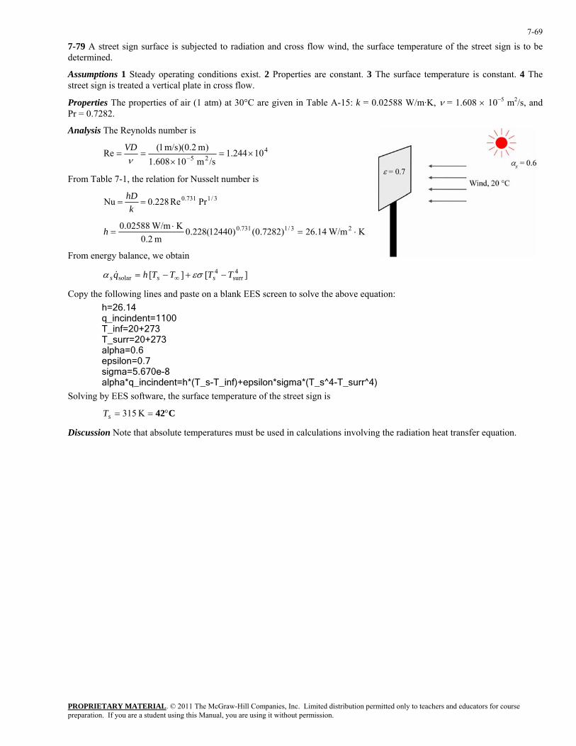
PROPRIETARY MATERIAL. © 2011 The McGraw-Hill Companies, Inc. Limited distribution permitted only to teachers and educators for course preparation. If you are a student using this Manual, you are using it without permission.
7-69
7-79 A street sign surface is subjected to radiation and cross flow wind, the surface temperature of the street sign is to be determined.
Assumptions 1 Steady operating conditions exist. 2 Properties are constant. 3 The surface temperature is constant. 4 The street sign is treated a vertical plate in cross flow.
Properties The properties of air (1 atm) at 30°C are given in Table A-15: k = 0.02588 W/m·K, ν = 1.608 × 10⁻⁵ m2/s, and Pr = 0.7282.
Analysis The Reynolds number is
425 10244.1/sm 10608.1
)m 2.0)(m/s 1(Re ×=×
==−ν
VD
From Table 7-1, the relation for Nusselt number is
3/1731.0 PrRe228.0Nu ==k
hD
K W/m14.26)7282.0()12440(228.0m 2.0
K W/m02588.0 23/1731.0 ⋅=⋅
=h
From energy balance, we obtain
][ ][ 4surr
4solar TTTThq sss −+−= ∞ εσα &
Copy the following lines and paste on a blank EES screen to solve the above equation: h=26.14 q_incindent=1100 T_inf=20+273 T_surr=20+273 alpha=0.6 epsilon=0.7 sigma=5.670e-8 alpha*q_incindent=h*(T_s-T_inf)+epsilon*sigma*(T_s^4-T_surr^4)
Solving by EES software, the surface temperature of the street sign is
C42°== K 315sT
Discussion Note that absolute temperatures must be used in calculations involving the radiation heat transfer equation.
PROPRIETARY MATERIAL. © 2011 The McGraw-Hill Companies, Inc. Limited distribution permitted only to teachers and educators for course preparation. If you are a student using this Manual, you are using it without permission.
7-70
Flow across Tube Banks
7-80C The level of turbulence, and thus the heat transfer coefficient, increases with row number because of the combined effects of upstream rows in turbulence caused and the wakes formed. But there is no significant change in turbulence level after the first few rows, and thus the heat transfer coefficient remains constant. There is no change in transverse direction.
7-81C In tube banks, the flow characteristics are dominated by the maximum velocity V max that occurs within the tube bank rather than the approach velocity V . Therefore, the Reynolds number is defined on the basis of maximum velocity.
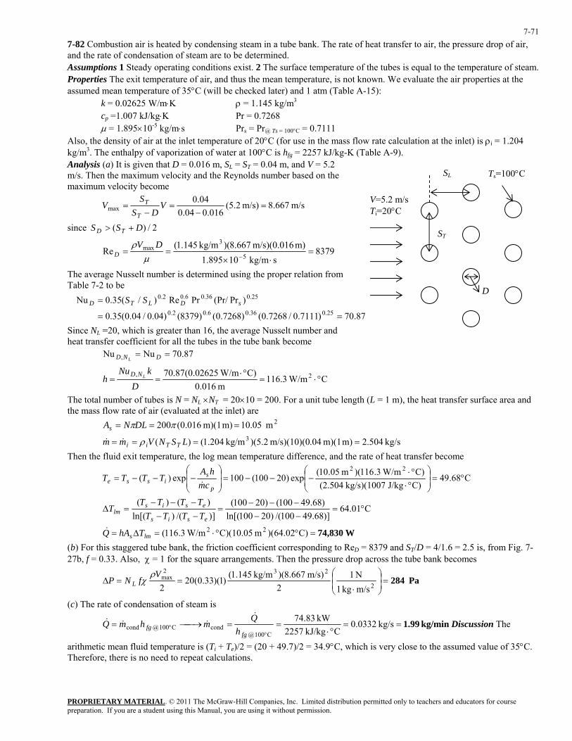
PROPRIETARY MATERIAL. © 2011 The McGraw-Hill Companies, Inc. Limited distribution permitted only to teachers and educators for course preparation. If you are a student using this Manual, you are using it without permission.
7-71
7-82 Combustion air is heated by condensing steam in a tube bank. The rate of heat transfer to air, the pressure drop of air, and the rate of condensation of steam are to be determined. Assumptions 1 Steady operating conditions exist. 2 The surface temperature of the tubes is equal to the temperature of steam. Properties The exit temperature of air, and thus the mean temperature, is not known. We evaluate the air properties at the assumed mean temperature of 35°C (will be checked later) and 1 atm (Table A-15):
k = 0.02625 W/m⋅K ρ = 1.145 kg/m3
cp =1.007 kJ/kg⋅K Pr = 0.7268 µ = 1.895×10⁻⁵ kg/m⋅s Prs = Pr@ Ts = 100°C = 0.7111
Also, the density of air at the inlet temperature of 20°C (for use in the mass flow rate calculation at the inlet) is ρi = 1.204 kg/m3. The enthalpy of vaporization of water at 100°C is hfg = 2257 kJ/kg-K (Table A-9). Analysis (a) It is given that D = 0.016 m, SL = ST = 0.04 m, and V = 5.2 m/s. Then the maximum velocity and the Reynolds number based on the maximum velocity become
m/s 667.8m/s) 2.5(016.004.0
04.0max =
−=
−= V
DSS
VT
T
since 2/)( DSS TD +>
8379skg/m 10895.1
m) m/s)(0.016 667.8)(kg/m 145.1(Re
5
3max =
⋅×==
−µρ DV
D
The average Nusselt number is determined using the proper relation from Table 7-2 to be
87.70)7111.0/7268.0()7268.0()8379()04.0/04.0(35.0
)Pr(Pr/PrRe)/(35.0Nu25.036.06.02.0
25.036.06.02.0
==
= sDLTD SS
SL
ST
V=5.2 m/s Ti=20°C
Ts=100°C
D
Since NL =20, which is greater than 16, the average Nusselt number and heat transfer coefficient for all the tubes in the tube bank become
87.70NuNu , == DND L
C W/m3.116m 0.016
C) W/m02625.0(87.70 2, °⋅=°⋅
==D
kNuh LND
The total number of tubes is N = NL ×NT = 20×10 = 200. For a unit tube length (L = 1 m), the heat transfer surface area and the mass flow rate of air (evaluated at the inlet) are
2m .0510 m) m)(1 016.0(200 === ππDLNAs
kg/s 504.2m) m)(1 .04m/s)(10)(0 2.5)(kg/m 204.1()( 3 ==== LSNVmm TTii ρ&& Then the fluid exit temperature, the log mean temperature difference, and the rate of heat transfer become
C68.49C)J/kg kg/s)(1007 (2.504C) W/m3.116)(m 05.10(
exp)20100(100exp)(22
°=⎟⎟⎠
⎞⎜⎜⎝
⎛
°⋅°⋅
−−−=⎟⎟⎠
⎞⎜⎜⎝
⎛−−−=
p
sisse cm
hATTTT
&
C01.64)]68.49100/()20100ln[()68.49100()20100(
)]/()ln[()()(
°=−−−−−
=−−−−−
=∆esis
esislm TTTT
TTTTT
W74,830=°°⋅=∆= )C02.64)(m C)(10.05 W/m3.116( 22lms ThAQ&
(b) For this staggered tube bank, the friction coefficient corresponding to ReD = 8379 and ST/D = 4/1.6 = 2.5 is, from Fig. 7-27b, f = 0.33. Also, χ = 1 for the square arrangements. Then the pressure drop across the tube bank becomes
Pa 284=⎟⎟⎠
⎞⎜⎜⎝
⎛
⋅==∆
2
232max
m/skg 1N 1
2m/s) 667.8)(kg/m 145.1()1)(33.0(20
2V
fNP Lρ
χ
(c) The rate of condensation of steam is
kg/min 1.99==°⋅
==⎯→⎯=°
° kg/s 0.0332CkJ/kg 2257
kW 83.74
C100@condC100@cond
fgfg h
QmhmQ&
&&& Discussion The
arithmetic mean fluid temperature is (Ti + Te)/2 = (20 + 49.7)/2 = 34.9°C, which is very close to the assumed value of 35°C. Therefore, there is no need to repeat calculations.
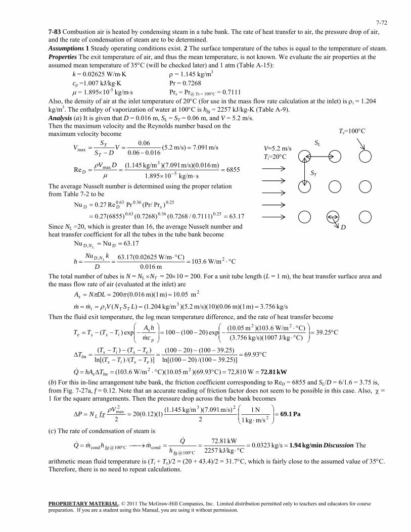
PROPRIETARY MATERIAL. © 2011 The McGraw-Hill Companies, Inc. Limited distribution permitted only to teachers and educators for course preparation. If you are a student using this Manual, you are using it without permission.
7-72
7-83 Combustion air is heated by condensing steam in a tube bank. The rate of heat transfer to air, the pressure drop of air, and the rate of condensation of steam are to be determined. Assumptions 1 Steady operating conditions exist. 2 The surface temperature of the tubes is equal to the temperature of steam. Properties The exit temperature of air, and thus the mean temperature, is not known. We evaluate the air properties at the assumed mean temperature of 35°C (will be checked later) and 1 atm (Table A-15):
k = 0.02625 W/m⋅K ρ = 1.145 kg/m3
cp =1.007 kJ/kg⋅K Pr = 0.7268 µ = 1.895×10⁻⁵ kg/m⋅s Prs = Pr@ Ts = 100°C = 0.7111
Also, the density of air at the inlet temperature of 20°C (for use in the mass flow rate calculation at the inlet) is ρi = 1.204 kg/m3. The enthalpy of vaporization of water at 100°C is hfg = 2257 kJ/kg-K (Table A-9). Analysis (a) It is given that D = 0.016 m, SL = ST = 0.06 m, and V = 5.2 m/s. Then the maximum velocity and the Reynolds number based on the maximum velocity become
SL
ST
V=5.2 m/s Ti=20°C
D
Ts=100°C
m/s 091.7m/s) 2.5(016.006.0
06.0max =
−=
−= V
DSS
VT
T
6855skg/m 10895.1
m) m/s)(0.016 091.7)(kg/m 145.1(Re
5
3max =
⋅×==
−µρ DV
D
The average Nusselt number is determined using the proper relation from Table 7-2 to be
17.63)7111.0/7268.0()7268.0()6855(27.0
)Pr(Pr/PrRe27.0Nu25.036.063.0
25.036.063.0
==
= sDD
Since NL =20, which is greater than 16, the average Nusselt number and heat transfer coefficient for all the tubes in the tube bank become
17.63NuNu , == DND L
C W/m6.103m 0.016
C) W/m02625.0(17.63 2, °⋅=°⋅
==D
kNuh LND
The total number of tubes is N = NL ×NT = 20×10 = 200. For a unit tube length (L = 1 m), the heat transfer surface area and the mass flow rate of air (evaluated at the inlet) are
2m .0510 m) m)(1 016.0(200 === ππDLNAs
kg/s 756.3m) m)(1 .06m/s)(10)(0 2.5)(kg/m 204.1()( 3 ==== LSNVmm TTii ρ&& Then the fluid exit temperature, the log mean temperature difference, and the rate of heat transfer become
C25.39C)J/kg kg/s)(1007 (3.756C) W/m6.103)(m 05.10(exp)20100(100exp)(
22°=⎟
⎟⎠
⎞⎜⎜⎝
⎛
°⋅°⋅
−−−=⎟⎟⎠
⎞⎜⎜⎝
⎛−−−=
p
sisse cm
hATTTT
&
C93.69)]25.39100/()20100ln[()25.39100()20100(
)]/()ln[()()(
°=−−−−−
=−−−−−
=∆esis
esislm TTTT
TTTTT
kW 72.81==°°⋅=∆= W72,810)C93.69)(m C)(10.05 W/m6.103( 22lms ThAQ&
(b) For this in-line arrangement tube bank, the friction coefficient corresponding to ReD = 6855 and SL/D = 6/1.6 = 3.75 is, from Fig. 7-27a, f = 0.12. Note that an accurate reading of friction factor does not seem to be possible in this case. Also, χ = 1 for the square arrangements. Then the pressure drop across the tube bank becomes
Pa 69.1=⎟⎟⎠
⎞⎜⎜⎝
⎛
⋅==∆
2
232max
m/skg 1N 1
2m/s) 091.7)(kg/m 145.1(
)1)(12.0(202
VfNP L
ρχ
(c) The rate of condensation of steam is
kg/min 1.94==°⋅
==⎯→⎯=°
° kg/s 0.0323CkJ/kg 2257
kW 81.72
C100@condC100@cond
fgfg h
QmhmQ&
&&& Discussion The
arithmetic mean fluid temperature is (Ti + Te)/2 = (20 + 43.4)/2 = 31.7°C, which is fairly close to the assumed value of 35°C. Therefore, there is no need to repeat calculations.
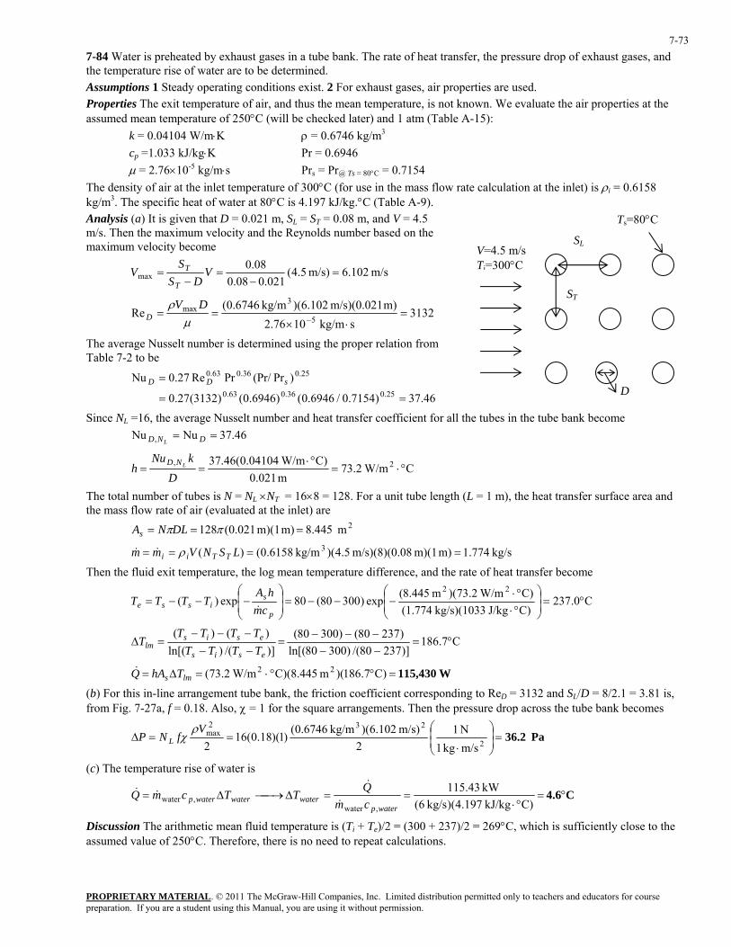
PROPRIETARY MATERIAL. © 2011 The McGraw-Hill Companies, Inc. Limited distribution permitted only to teachers and educators for course preparation. If you are a student using this Manual, you are using it without permission.
7-73
7-84 Water is preheated by exhaust gases in a tube bank. The rate of heat transfer, the pressure drop of exhaust gases, and the temperature rise of water are to be determined. Assumptions 1 Steady operating conditions exist. 2 For exhaust gases, air properties are used. Properties The exit temperature of air, and thus the mean temperature, is not known. We evaluate the air properties at the assumed mean temperature of 250°C (will be checked later) and 1 atm (Table A-15):
k = 0.04104 W/m⋅K ρ = 0.6746 kg/m3
cp =1.033 kJ/kg⋅K Pr = 0.6946 µ = 2.76×10⁻⁵ kg/m⋅s Prs = Pr@ Ts = 80°C = 0.7154
The density of air at the inlet temperature of 300°C (for use in the mass flow rate calculation at the inlet) is ρi = 0.6158 kg/m3. The specific heat of water at 80°C is 4.197 kJ/kg.°C (Table A-9). Analysis (a) It is given that D = 0.021 m, SL = ST = 0.08 m, and V = 4.5 m/s. Then the maximum velocity and the Reynolds number based on the maximum velocity become SL
ST
V=4.5 m/s Ti=300°C
D
Ts=80°C
m/s 102.6m/s) 5.4(021.008.0
08.0max =
−=
−= V
DSS
VT
T
3132skg/m 1076.2
m) m/s)(0.021 102.6)(kg/m 6746.0(Re
5
3max =
⋅×==
−µρ DV
D
The average Nusselt number is determined using the proper relation from Table 7-2 to be
46.37)7154.0/6946.0()6946.0()3132(27.0
)Pr(Pr/PrRe27.0Nu25.036.063.0
25.036.063.0
==
= sDD
Since NL =16, the average Nusselt number and heat transfer coefficient for all the tubes in the tube bank become 46.37NuNu , == DND L
C W/m2.73m 0.021
C) W/m04104.0(46.37 2, °⋅=°⋅
==D
kNuh LND
The total number of tubes is N = NL ×NT = 16×8 = 128. For a unit tube length (L = 1 m), the heat transfer surface area and the mass flow rate of air (evaluated at the inlet) are
2m .4458 m) m)(1 021.0(128 === ππDLNAs
kg/s 774.1m) m)(1 08m/s)(8)(0. 5.4)(kg/m 6158.0()( 3 ==== LSNVmm TTii ρ&&
Then the fluid exit temperature, the log mean temperature difference, and the rate of heat transfer become
C0.237C)J/kg kg/s)(1033 (1.774C) W/m2.73)(m 445.8(
exp)30080(80exp)(22
°=⎟⎟⎠
⎞⎜⎜⎝
⎛
°⋅°⋅
−−−=⎟⎟⎠
⎞⎜⎜⎝
⎛−−−=
p
sisse cm
hATTTT
&
C7.186)]23780/()30080ln[()23780()30080(
)]/()ln[()()(
°=−−−−−
=−−−−−
=∆esis
esislm TTTT
TTTTT
W115,430=°°⋅=∆= )C7.186)(m C)(8.445 W/m2.73( 22lms ThAQ&
(b) For this in-line arrangement tube bank, the friction coefficient corresponding to ReD = 3132 and SL/D = 8/2.1 = 3.81 is, from Fig. 7-27a, f = 0.18. Also, χ = 1 for the square arrangements. Then the pressure drop across the tube bank becomes
Pa 36.2=⎟⎟⎠
⎞⎜⎜⎝
⎛
⋅==∆
2
232max
m/skg 1N 1
2m/s) 102.6)(kg/m 6746.0()1)(18.0(16
2V
fNP Lρ
χ
(c) The temperature rise of water is
C4.6 °=°⋅
==∆⎯→⎯∆=C)kJ/kg 197.4)(kg/s 6(
kW 43.115
,water,water
waterpwaterwaterwaterp cm
QTTcmQ&
&&&
Discussion The arithmetic mean fluid temperature is (Ti + Te)/2 = (300 + 237)/2 = 269°C, which is sufficiently close to the assumed value of 250°C. Therefore, there is no need to repeat calculations.
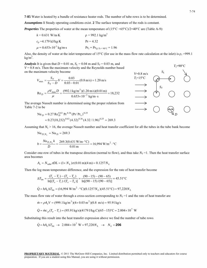
PROPRIETARY MATERIAL. © 2011 The McGraw-Hill Companies, Inc. Limited distribution permitted only to teachers and educators for course preparation. If you are a student using this Manual, you are using it without permission.
7-74
7-85 Water is heated by a bundle of resistance heater rods. The number of tube rows is to be determined.
Assumptions 1 Steady operating conditions exist. 2 The surface temperature of the rods is constant.
Properties The properties of water at the mean temperature of (15°C +65°C)/2=40°C are (Table A-9):
k = 0.631 W/m⋅K ρ = 992.1 kg/m3
cp =4.179 kJ/kg⋅K Pr = 4.32
µ = 0.653×10⁻³ kg/m⋅s Prs = Pr@ Ts = 90°C = 1.96
Also, the density of water at the inlet temperature of 15°C (for use in the mass flow rate calculation at the inlet) is ρi =999.1 kg/m3.
Analysis It is given that D = 0.01 m, SL = 0.04 m and ST = 0.03 m, and V = 0.8 m/s. Then the maximum velocity and the Reynolds number based on the maximum velocity become SL
ST
V=0.8 m/s Ti=15°C
D
Ts=90°C
m/s 20.1m/s) 8.0(01.003.0
03.0max =
−=
−= V
DSS
VT
T
232,18skg/m 10653.0
m) m/s)(0.01 20.1)(kg/m 1.992(Re
3
3max =
⋅×==
−µρ DV
D
The average Nusselt number is determined using the proper relation from Table 7-2 to be
3.269)96.1/32.4()32.4()232,18(27.0
)Pr(Pr/PrRe27.0Nu25.036.063.0
25.036.063.0
==
= sDD
Assuming that NL > 16, the average Nusselt number and heat transfer coefficient for all the tubes in the tube bank become
3.269NuNu , == DND L
C W/m994,16m 0.01
C) W/m631.0(3.269 2, °⋅=°⋅
==D
kNuh LND
Consider one-row of tubes in the transpose direction (normal to flow), and thus take NT =1. Then the heat transfer surface area becomes
LLtubes NNDLNA 1257.0 m) m)(4 01.0()1( =×== ππ
Then the log mean temperature difference, and the expression for the rate of heat transfer become
C51.45)]6590/()1590ln[()6590()1590(
)]/()ln[()()(
°=−−−−−
=−−−−−
=∆esis
esislm TTTT
TTTTT
LLlms NNThAQ 220,97)C51.45()C)(0.1257 W/m994,16( 2 =°°⋅=∆=&
The mass flow rate of water through a cross-section corresponding to NT =1 and the rate of heat transfer are
kg/s 91.95m/s) )(0.8m 0.03)(4kg/m 1.999( 23 =×== VAm cρ&
W10004.2C)1565(J/kg.C) kg/s)(4179 91.95()( 7×=°−=−= iep TTcmQ &&
Substituting this result into the heat transfer expression above we find the number of tube rows
206=→=×→∆= LLlms NNThAQ 220,97 W10004.2 7&
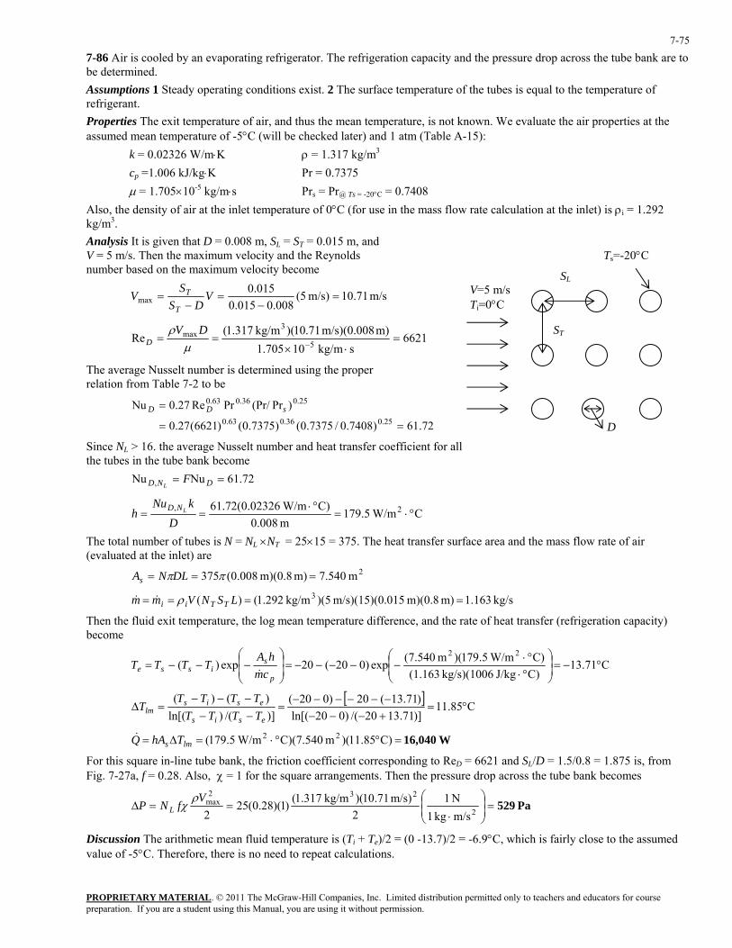
PROPRIETARY MATERIAL. © 2011 The McGraw-Hill Companies, Inc. Limited distribution permitted only to teachers and educators for course preparation. If you are a student using this Manual, you are using it without permission.
7-75
7-86 Air is cooled by an evaporating refrigerator. The refrigeration capacity and the pressure drop across the tube bank are to be determined. Assumptions 1 Steady operating conditions exist. 2 The surface temperature of the tubes is equal to the temperature of refrigerant. Properties The exit temperature of air, and thus the mean temperature, is not known. We evaluate the air properties at the assumed mean temperature of -5°C (will be checked later) and 1 atm (Table A-15):
k = 0.02326 W/m⋅K ρ = 1.317 kg/m3
cp =1.006 kJ/kg⋅K Pr = 0.7375 µ = 1.705×10⁻⁵ kg/m⋅s Prs = Pr@ Ts = -20°C = 0.7408
Also, the density of air at the inlet temperature of 0°C (for use in the mass flow rate calculation at the inlet) is ρi = 1.292 kg/m3. Analysis It is given that D = 0.008 m, SL = ST = 0.015 m, and V = 5 m/s. Then the maximum velocity and the Reynolds number based on the maximum velocity become SL
ST
V=5 m/sTi=0°C
D
Ts=-20°C
m/s 71.10m/s) 5(008.0015.0
015.0max =
−=
−= V
DSS
VT
T
6621skg/m 10705.1
m) m/s)(0.008 71.10)(kg/m 317.1(Re 5
3max =
⋅×==
−µρ DV
D
The average Nusselt number is determined using the proper relation from Table 7-2 to be
72.61)7408.0/7375.0()7375.0()6621(27.0
)Pr(Pr/PrRe27.0Nu25.036.063.0
25.036.063.0
==
= sDD
Since NL > 16. the average Nusselt number and heat transfer coefficient for all the tubes in the tube bank become
72.61NuNu , == DND FL
C W/m5.179m 0.008
C) W/m02326.0(72.61 2, °⋅=°⋅
==D
kNuh LND
The total number of tubes is N = NL ×NT = 25×15 = 375. The heat transfer surface area and the mass flow rate of air (evaluated at the inlet) are
2m .5407 m) m)(0.8 008.0(375 === ππDLNAs
kg/s 163.1m) m)(0.8 .015m/s)(15)(0 5)(kg/m 292.1()( 3 ==== LSNVmm TTii ρ&&
Then the fluid exit temperature, the log mean temperature difference, and the rate of heat transfer (refrigeration capacity) become
C71.13C)J/kg kg/s)(1006 (1.163C) W/m5.179)(m 540.7(exp)020(20exp)(
22°−=⎟
⎟⎠
⎞⎜⎜⎝
⎛
°⋅°⋅
−−−−−=⎟⎟⎠
⎞⎜⎜⎝
⎛−−−=
p
sisse cm
hATTTT
&
[ ] C85.11)]71.1320/()020ln[()71.13(20)020(
)]/()ln[()()(
°=+−−−−−−−−−
=−−−−−
=∆esis
esislm TTTT
TTTTT
W16,040=°°⋅=∆= )C85.11)(m C)(7.540 W/m5.179( 22lms ThAQ&
For this square in-line tube bank, the friction coefficient corresponding to ReD = 6621 and SL/D = 1.5/0.8 = 1.875 is, from Fig. 7-27a, f = 0.28. Also, χ = 1 for the square arrangements. Then the pressure drop across the tube bank becomes
Pa 529=⎟⎟⎠
⎞⎜⎜⎝
⎛
⋅==∆ 2
232max
m/skg 1N 1
2m/s) 71.10)(kg/m 317.1()1)(28.0(25
2V
fNP Lρ
χ
Discussion The arithmetic mean fluid temperature is (Ti + Te)/2 = (0 -13.7)/2 = -6.9°C, which is fairly close to the assumed value of -5°C. Therefore, there is no need to repeat calculations.
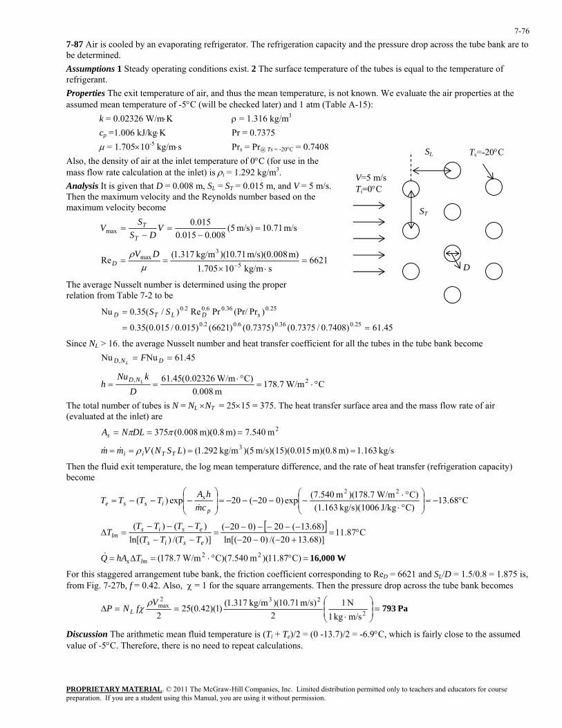
PROPRIETARY MATERIAL. © 2011 The McGraw-Hill Companies, Inc. Limited distribution permitted only to teachers and educators for course preparation. If you are a student using this Manual, you are using it without permission.
7-76
7-87 Air is cooled by an evaporating refrigerator. The refrigeration capacity and the pressure drop across the tube bank are to be determined. Assumptions 1 Steady operating conditions exist. 2 The surface temperature of the tubes is equal to the temperature of refrigerant. Properties The exit temperature of air, and thus the mean temperature, is not known. We evaluate the air properties at the assumed mean temperature of -5°C (will be checked later) and 1 atm (Table A-15):
k = 0.02326 W/m⋅K ρ = 1.316 kg/m3
cp =1.006 kJ/kg⋅K Pr = 0.7375 µ = 1.705×10⁻⁵ kg/m⋅s Prs = Pr@ Ts = -20°C = 0.7408 SL
ST
V=5 m/sTi=0°C
Ts=-20°C
D
Also, the density of air at the inlet temperature of 0°C (for use in the mass flow rate calculation at the inlet) is ρi = 1.292 kg/m3. Analysis It is given that D = 0.008 m, SL = ST = 0.015 m, and V = 5 m/s. Then the maximum velocity and the Reynolds number based on the maximum velocity become
m/s 71.10m/s) 5(008.0015.0
015.0max =
−=
−= V
DSS
VT
T
6621skg/m 10705.1
m) m/s)(0.008 71.10)(kg/m 317.1(Re 5
3max =
⋅×==
−µρ DV
D
The average Nusselt number is determined using the proper relation from Table 7-2 to be
45.61)7408.0/7375.0()7375.0()6621()015.0/015.0(35.0
)Pr(Pr/PrRe)/(35.0Nu25.036.06.02.0
25.036.06.02.0
==
= sDLTD SS
Since NL > 16. the average Nusselt number and heat transfer coefficient for all the tubes in the tube bank become 45.61NuNu , == DND F
L
C W/m7.178m 0.008
C) W/m02326.0(45.61 2, °⋅=°⋅
==D
kNuh LND
The total number of tubes is N = NL ×NT = 25×15 = 375. The heat transfer surface area and the mass flow rate of air (evaluated at the inlet) are
2m .5407 m) m)(0.8 008.0(375 === ππDLNAs
kg/s 163.1m) m)(0.8 .015m/s)(15)(0 5)(kg/m 292.1()( 3 ==== LSNVmm TTii ρ&&
Then the fluid exit temperature, the log mean temperature difference, and the rate of heat transfer (refrigeration capacity) become
C68.13C)J/kg kg/s)(1006 (1.163C) W/m7.178)(m 540.7(exp)020(20exp)(
22°−=⎟
⎟⎠
⎞⎜⎜⎝
⎛
°⋅°⋅
−−−−−=⎟⎟⎠
⎞⎜⎜⎝
⎛−−−=
p
sisse cm
hATTTT
&
[ ] C87.11)]68.1320/()020ln[()68.13(20)020(
)]/()ln[()()(
°=+−−−−−−−−−
=−−−−−
=∆esis
esislm TTTT
TTTTT
W16,000=°°⋅=∆= )C87.11)(m C)(7.540 W/m7.178( 22lms ThAQ&
For this staggered arrangement tube bank, the friction coefficient corresponding to ReD = 6621 and SL/D = 1.5/0.8 = 1.875 is, from Fig. 7-27b, f = 0.42. Also, χ = 1 for the square arrangements. Then the pressure drop across the tube bank becomes
Pa 793=⎟⎟⎠
⎞⎜⎜⎝
⎛
⋅==∆ 2
232max
m/skg 1N 1
2m/s) 71.10)(kg/m 317.1()1)(42.0(25
2V
fNP Lρ
χ
Discussion The arithmetic mean fluid temperature is (Ti + Te)/2 = (0 -13.7)/2 = -6.9°C, which is fairly close to the assumed value of -5°C. Therefore, there is no need to repeat calculations.
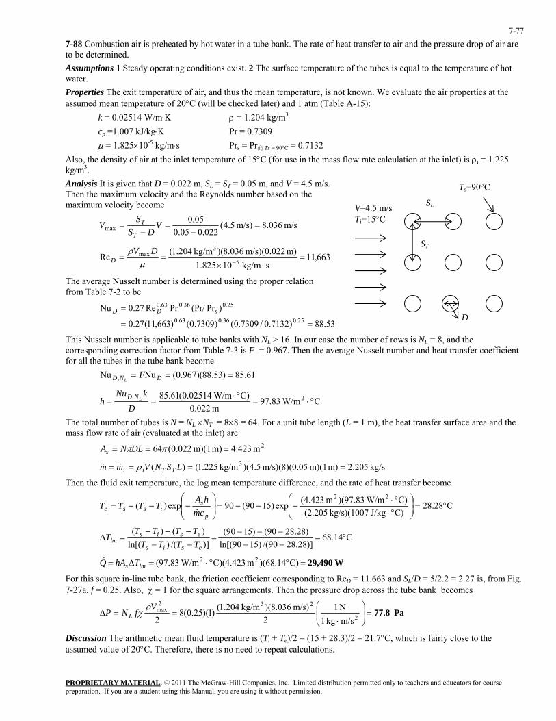
PROPRIETARY MATERIAL. © 2011 The McGraw-Hill Companies, Inc. Limited distribution permitted only to teachers and educators for course preparation. If you are a student using this Manual, you are using it without permission.
7-77
7-88 Combustion air is preheated by hot water in a tube bank. The rate of heat transfer to air and the pressure drop of air are to be determined. Assumptions 1 Steady operating conditions exist. 2 The surface temperature of the tubes is equal to the temperature of hot water. Properties The exit temperature of air, and thus the mean temperature, is not known. We evaluate the air properties at the assumed mean temperature of 20°C (will be checked later) and 1 atm (Table A-15):
k = 0.02514 W/m⋅K ρ = 1.204 kg/m3
cp =1.007 kJ/kg⋅K Pr = 0.7309 µ = 1.825×10⁻⁵ kg/m⋅s Prs = Pr@ Ts = 90°C = 0.7132
Also, the density of air at the inlet temperature of 15°C (for use in the mass flow rate calculation at the inlet) is ρi = 1.225 kg/m3. Analysis It is given that D = 0.022 m, SL = ST = 0.05 m, and V = 4.5 m/s. Then the maximum velocity and the Reynolds number based on the maximum velocity become SL
ST
V=4.5 m/s Ti=15°C
D
Ts=90°C
m/s 036.8m/s) 5.4(022.005.0
05.0max =
−=
−= V
DSS
VT
T
663,11skg/m 10825.1
m) m/s)(0.022 036.8)(kg/m 204.1(Re 5
3max =
⋅×==
−µρ DV
D
The average Nusselt number is determined using the proper relation from Table 7-2 to be
53.88)7132.0/7309.0()7309.0()663,11(27.0
)Pr(Pr/PrRe27.0Nu25.036.063.0
25.036.063.0
==
= sDD
This Nusselt number is applicable to tube banks with NL > 16. In our case the number of rows is NL = 8, and the corresponding correction factor from Table 7-3 is F = 0.967. Then the average Nusselt number and heat transfer coefficient for all the tubes in the tube bank become
61.85)53.88)(967.0(NuNu , === DND FL
C W/m83.97m 0.022
C) W/m02514.0(61.85 2, °⋅=°⋅
==D
kNuh LND
The total number of tubes is N = NL ×NT = 8×8 = 64. For a unit tube length (L = 1 m), the heat transfer surface area and the mass flow rate of air (evaluated at the inlet) are
2m .4234 m) m)(1 022.0(64 === ππDLNAs
kg/s 205.2m) m)(1 05m/s)(8)(0. 5.4)(kg/m 225.1()( 3 ==== LSNVmm TTii ρ&&
Then the fluid exit temperature, the log mean temperature difference, and the rate of heat transfer become
C28.28C)J/kg kg/s)(1007 (2.205C) W/m83.97)(m 423.4(exp)1590(90exp)(
22°=⎟
⎟⎠
⎞⎜⎜⎝
⎛
°⋅°⋅
−−−=⎟⎟⎠
⎞⎜⎜⎝
⎛−−−=
p
sisse cm
hATTTT
&
C14.68)]28.2890/()1590ln[()28.2890()1590(
)]/()ln[()()(
°=−−−−−
=−−−−−
=∆esis
esislm TTTT
TTTTT
W29,490=°°⋅=∆= )C14.68)(m C)(4.423 W/m83.97( 22lms ThAQ&
For this square in-line tube bank, the friction coefficient corresponding to ReD = 11,663 and SL/D = 5/2.2 = 2.27 is, from Fig. 7-27a, f = 0.25. Also, χ = 1 for the square arrangements. Then the pressure drop across the tube bank becomes
Pa 77.8=⎟⎟⎠
⎞⎜⎜⎝
⎛
⋅==∆ 2
232max
m/skg 1N 1
2m/s) 036.8)(kg/m 204.1()1)(25.0(8
2V
fNP Lρ
χ
Discussion The arithmetic mean fluid temperature is (Ti + Te)/2 = (15 + 28.3)/2 = 21.7°C, which is fairly close to the assumed value of 20°C. Therefore, there is no need to repeat calculations.
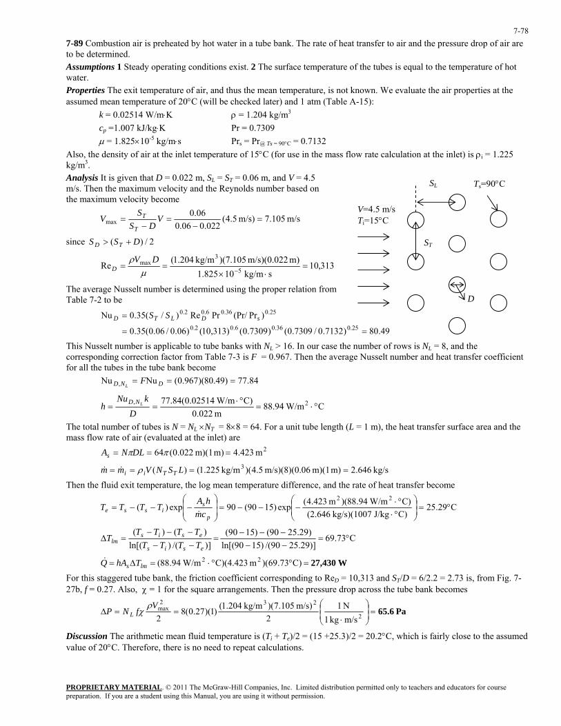
PROPRIETARY MATERIAL. © 2011 The McGraw-Hill Companies, Inc. Limited distribution permitted only to teachers and educators for course preparation. If you are a student using this Manual, you are using it without permission.
7-78
7-89 Combustion air is preheated by hot water in a tube bank. The rate of heat transfer to air and the pressure drop of air are to be determined. Assumptions 1 Steady operating conditions exist. 2 The surface temperature of the tubes is equal to the temperature of hot water. Properties The exit temperature of air, and thus the mean temperature, is not known. We evaluate the air properties at the assumed mean temperature of 20°C (will be checked later) and 1 atm (Table A-15):
k = 0.02514 W/m⋅K ρ = 1.204 kg/m3
cp =1.007 kJ/kg⋅K Pr = 0.7309 µ = 1.825×10⁻⁵ kg/m⋅s Prs = Pr@ Ts = 90°C = 0.7132
Also, the density of air at the inlet temperature of 15°C (for use in the mass flow rate calculation at the inlet) is ρi = 1.225 kg/m3. Analysis It is given that D = 0.022 m, SL = ST = 0.06 m, and V = 4.5 m/s. Then the maximum velocity and the Reynolds number based on the maximum velocity become
m/s 105.7m/s) 5.4(022.006.0
06.0max =
−=
−= V
DSS
VT
T
since 2/)( DSS TD +>
313,10skg/m 10825.1
m) m/s)(0.022 105.7)(kg/m 204.1(Re 5
3max =
⋅×==
−µρ DV
D
The average Nusselt number is determined using the proper relation from Table 7-2 to be
49.80)7132.0/7309.0()7309.0()313,10()06.0/06.0(35.0
)Pr(Pr/PrRe)/(35.0Nu25.036.06.02.0
25.036.06.02.0
==
= sDLTD SS
SL
ST
V=4.5 m/s Ti=15°C
Ts=90°C
D
This Nusselt number is applicable to tube banks with NL > 16. In our case the number of rows is NL = 8, and the corresponding correction factor from Table 7-3 is F = 0.967. Then the average Nusselt number and heat transfer coefficient for all the tubes in the tube bank become
84.77)49.80)(967.0(NuNu , === DND FL
C W/m94.88m 0.022
C) W/m02514.0(84.77 2, °⋅=°⋅
==D
kNuh LND
The total number of tubes is N = NL ×NT = 8×8 = 64. For a unit tube length (L = 1 m), the heat transfer surface area and the mass flow rate of air (evaluated at the inlet) are
2m .4234 m) m)(1 022.0(64 === ππDLNAs
kg/s 646.2m) m)(1 06m/s)(8)(0. 5.4)(kg/m 225.1()( 3 ==== LSNVmm TTii ρ&&
Then the fluid exit temperature, the log mean temperature difference, and the rate of heat transfer become
C29.25C)J/kg kg/s)(1007 (2.646C) W/m94.88)(m 423.4(exp)1590(90exp)(
22°=⎟
⎟⎠
⎞⎜⎜⎝
⎛
°⋅°⋅
−−−=⎟⎟⎠
⎞⎜⎜⎝
⎛−−−=
p
sisse cm
hATTTT
&
C73.69)]29.2590/()1590ln[()29.2590()1590(
)]/()ln[()()(
°=−−−−−
=−−−−−
=∆esis
esislm TTTT
TTTTT
W27,430=°°⋅=∆= )C73.69)(m C)(4.423 W/m94.88( 22lms ThAQ&
For this staggered tube bank, the friction coefficient corresponding to ReD = 10,313 and ST/D = 6/2.2 = 2.73 is, from Fig. 7-27b, f = 0.27. Also, χ = 1 for the square arrangements. Then the pressure drop across the tube bank becomes
Pa 65.6=⎟⎟⎠
⎞⎜⎜⎝
⎛
⋅==∆ 2
232max
m/skg 1N 1
2m/s) 105.7)(kg/m 204.1()1)(27.0(8
2V
fNP Lρ
χ
Discussion The arithmetic mean fluid temperature is (Ti + Te)/2 = (15 +25.3)/2 = 20.2°C, which is fairly close to the assumed value of 20°C. Therefore, there is no need to repeat calculations.
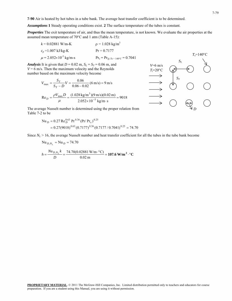
PROPRIETARY MATERIAL. © 2011 The McGraw-Hill Companies, Inc. Limited distribution permitted only to teachers and educators for course preparation. If you are a student using this Manual, you are using it without permission.
7-79
7-90 Air is heated by hot tubes in a tube bank. The average heat transfer coefficient is to be determined.
Assumptions 1 Steady operating conditions exist. 2 The surface temperature of the tubes is constant.
Properties The exit temperature of air, and thus the mean temperature, is not known. We evaluate the air properties at the assumed mean temperature of 70°C and 1 atm (Table A-15):
k = 0.02881 W/m-K ρ = 1.028 kg/m3
cp =1.007 kJ/kg-K Pr = 0.7177
SL
ST
V=6 m/s Ti=20°C
D
Ts=140°C µ = 2.052×10⁻⁵ kg/m-s Prs = Pr@ Ts = 140°C = 0.7041
Analysis It is given that D = 0.02 m, SL = ST = 0.06 m, and V = 6 m/s. Then the maximum velocity and the Reynolds number based on the maximum velocity become
m/s 9m/s) 6(02.006.0
06.0max =
−=
−= V
DSS
VT
T
9018skg/m 10052.2
m) m/s)(0.02 9)(kg/m 028.1(Re
5
3max =
⋅×==
−µρ DV
D
The average Nusselt number is determined using the proper relation from Table 7-2 to be
70.74)7041.0/7177.0()7177.0()9018(27.0
)Pr(Pr/PrRe27.0Nu25.036.063.0
25.036.063.0
==
= sDD
Since NL > 16, the average Nusselt number and heat transfer coefficient for all the tubes in the tube bank become
70.74NuNu , == DND L
C W/m107.6 2 °⋅=°⋅
==m 0.02
C) W/m02881.0(70.74,
D
kNuh LND
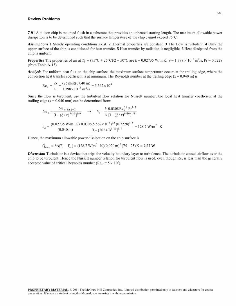
PROPRIETARY MATERIAL. © 2011 The McGraw-Hill Companies, Inc. Limited distribution permitted only to teachers and educators for course preparation. If you are a student using this Manual, you are using it without permission.
7-80
Review Problems
7-91 A silicon chip is mounted flush in a substrate that provides an unheated starting length. The maximum allowable power dissipation is to be determined such that the surface temperature of the chip cannot exceed 75°C.
Assumptions 1 Steady operating conditions exist. 2 Thermal properties are constant. 3 The flow is turbulent. 4 Only the upper surface of the chip is conditioned for heat transfer. 5 Heat transfer by radiation is negligible. 6 Heat dissipated from the chip is uniform.
Properties The properties of air at Tf = (75°C + 25°C)/2 = 50°C are k = 0.02735 W/m·K, ν = 1.798 × 10⁻⁵ m2/s, Pr = 0.7228 (from Table A-15).
Analysis For uniform heat flux on the chip surface, the maximum surface temperature occurs at the trailing edge, where the convection heat transfer coefficient is at minimum. The Reynolds number at the trailing edge (x = 0.040 m) is
425 10562.5/sm 10798.1)m 040.0)(m/s 25(Re ×=
×==
−νVx
x
Since the flow is turbulent, use the turbulent flow relation for Nusselt number, the local heat transfer coefficient at the trailing edge (x = 0.040 mm) can be determined from:
9/110/9)0for (
])/(1[
NuNu
xx
xξ
ξ
−= = → 9/110/9
3/18.0
])/(1[PrRe0308.0
xxkh x
xξ−
=
K W/m7.128])40/20(1[
)7228.0()10562.5(0308.0)m 040.0(
)K W/m02735.0( 29/110/9
3/18.04⋅=
−
×⋅=xh
Hence, the maximum allowable power dissipation on the chip surface is
W2.57=−⋅=−= ∞ K )2575()m 020.0)(K W/m7.128()( 22max TThAQ s&
Discussion Turbulator is a device that trips the velocity boundary layer to turbulence. The turbulator caused airflow over the chip to be turbulent. Hence the Nusselt number relation for turbulent flow is used, even though Rex is less than the generally accepted value of critical Reynolds number (Recr = 5 × 10⁵).
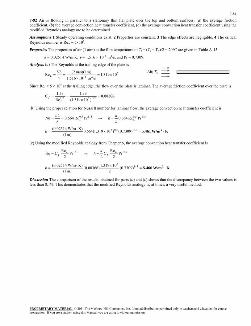
PROPRIETARY MATERIAL. © 2011 The McGraw-Hill Companies, Inc. Limited distribution permitted only to teachers and educators for course preparation. If you are a student using this Manual, you are using it without permission.
7-81
7-92 Air is flowing in parallel to a stationary thin flat plate over the top and bottom surfaces: (a) the average friction coefficient, (b) the average convection heat transfer coefficient, (c) the average convection heat transfer coefficient using the modified Reynolds analogy are to be determined.
Assumptions 1 Steady operating conditions exist. 2 Properties are constant. 3 The edge effects are negligible. 4 The critical Reynolds number is Recr = 5×10⁵.
Properties The properties of air (1 atm) at the film temperature of Tf = (Ts + T∞)/2 = 20°C are given in Table A-15:
k = 0.02514 W/m·K, ν = 1.516 × 10⁻⁵ m2/s, and Pr = 0.7309.
Analysis (a) The Reynolds at the trailing edge of the plate is
525 10319.1/sm 10516.1
)m 1)(m/s 2(Re ×=×
==−ν
VLL
Since Rex < 5 × 10⁵ at the trailing edge, the flow over the plate is laminar. The average friction coefficient over the plate is
0.00366=×
== 2/152/1 )10319.1(33.1
Re33.1
LfC
(b) Using the proper relation for Nusselt number for laminar flow, the average convection heat transfer coefficient is
3/15.0 PrRe664.0Nu LkhL
== → 3/15.0 PrRe664.0 LLkh =
K W/m5.461 2 ⋅=×⋅
= 3/15.05 )7309.0()10319.1(664.0)m 1(
K) W/m02514.0(h
(c) Using the modified Reynolds analogy from Chapter 6, the average convection heat transfer coefficient is
3/1Pr2
ReNu L
fC= → 3/1Pr2
Re LfC
Lkh =
K W/m5.466 2 ⋅=×⋅
= 3/15
)7309.0(2
10319.1)00366.0()m 1(
K) W/m02514.0(h
Discussion The comparison of the results obtained for parts (b) and (c) shows that the discrepancy between the two values is less than 0.1%. This demonstrates that the modified Reynolds analogy is, at times, a very useful method.
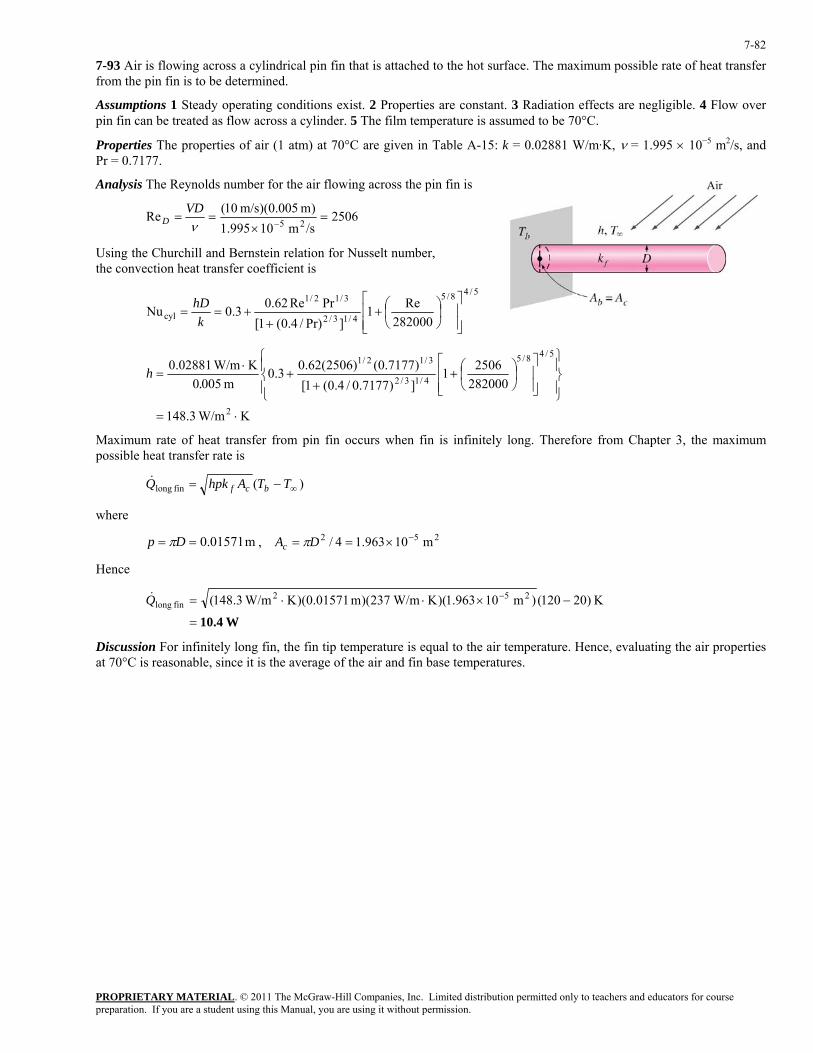
PROPRIETARY MATERIAL. © 2011 The McGraw-Hill Companies, Inc. Limited distribution permitted only to teachers and educators for course preparation. If you are a student using this Manual, you are using it without permission.
7-82
7-93 Air is flowing across a cylindrical pin fin that is attached to the hot surface. The maximum possible rate of heat transfer from the pin fin is to be determined.
Assumptions 1 Steady operating conditions exist. 2 Properties are constant. 3 Radiation effects are negligible. 4 Flow over pin fin can be treated as flow across a cylinder. 5 The film temperature is assumed to be 70°C.
Properties The properties of air (1 atm) at 70°C are given in Table A-15: k = 0.02881 W/m·K, ν = 1.995 × 10⁻⁵ m2/s, and Pr = 0.7177.
Analysis The Reynolds number for the air flowing across the pin fin is
2506/sm 10995.1)m 005.0)(m/s 10(Re 25 =
×==
−νVD
D
Using the Churchill and Bernstein relation for Nusselt number, the convection heat transfer coefficient is
5/48/5
4/13/2
3/12/1
cyl 282000Re1
]Pr)/4.0(1[PrRe62.03.0Nu
⎥⎥⎦
⎤
⎢⎢⎣
⎡⎟⎠⎞
⎜⎝⎛+
++==
khD
K W/m3.148
28200025061
])7177.0/4.0(1[)7177.0()2506(62.03.0
m 0050K W/m02881.0
2
5/48/5
4/13/2
3/12/1
⋅=
⎪⎭
⎪⎬⎫
⎪⎩
⎪⎨⎧
⎥⎥⎦
⎤
⎢⎢⎣
⎡⎟⎠⎞
⎜⎝⎛+
++
⋅=
.h
Maximum rate of heat transfer from pin fin occurs when fin is infinitely long. Therefore from Chapter 3, the maximum possible heat transfer rate is
)(fin long ∞−= TTAhpkQ bcf&
where
m 01571.0== Dp π , 252 m 10963.14/ −×== DAc π
Hence
W10.4=
−×⋅⋅= − K )20120()m 10963.1)(K W/m237)(m 01571.0)(K W/m3.148( 252fin longQ&
Discussion For infinitely long fin, the fin tip temperature is equal to the air temperature. Hence, evaluating the air properties at 70°C is reasonable, since it is the average of the air and fin base temperatures.
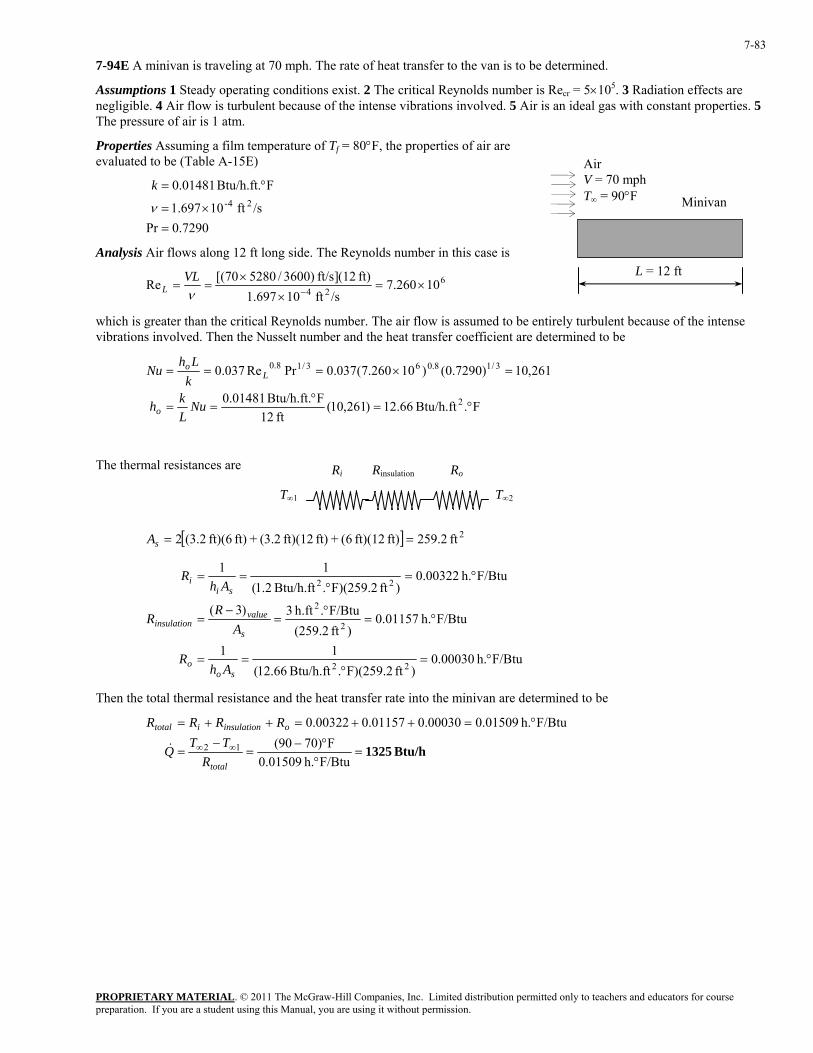
PROPRIETARY MATERIAL. © 2011 The McGraw-Hill Companies, Inc. Limited distribution permitted only to teachers and educators for course preparation. If you are a student using this Manual, you are using it without permission.
7-83
7-94E A minivan is traveling at 70 mph. The rate of heat transfer to the van is to be determined.
Assumptions 1 Steady operating conditions exist. 2 The critical Reynolds number is Recr = 5×10⁵. 3 Radiation effects are negligible. 4 Air flow is turbulent because of the intense vibrations involved. 5 Air is an ideal gas with constant properties. 5 The pressure of air is 1 atm.
Properties Assuming a film temperature of Tf = 80°F, the properties of air are evaluated to be (Table A-15E)
Minivan
Air V = 70 mph T∞ = 90°F
7290.0Pr
/sft 10697.1
FBtu/h.ft. 01481.024-
=×=
°=
ν
k
Analysis Air flows along 12 ft long side. The Reynolds number in this case is L = 12 ft
624 10260.7/sft 10697.1
ft) (12]ft/s )3600/528070[(Re ×=×
×==
−νVL
L
which is greater than the critical Reynolds number. The air flow is assumed to be entirely turbulent because of the intense vibrations involved. Then the Nusselt number and the heat transfer coefficient are determined to be
F.Btu/h.ft 66.12)261,10(
ft 12FBtu/h.ft. 01481.0
261,10)7290.0()10260.7(037.0PrRe037.0
2
3/18.063/18.0
°=°
==
=×===
NuLkh
kLh
Nu
o
Lo
The thermal resistances are Ri Rinsulation Ro
T∞1 T∞2
[ ] 2ft 2.259ft) ft)(12 6(+ft) ft)(12 2.3(+ft) ft)(6 2.3(2 ==sA
F/Btuh. 00030.0)ft F)(259.2.Btu/h.ft 66.12(
11
F/Btuh. 01157.0)ft (259.2
F/Btu.h.ft 3)3(
F/Btuh. 00322.0)ft F)(259.2.Btu/h.ft 2.1(
11
22
2
2
22
°=°
==
°=°
=−
=
°=°
==
soo
s
valueinsulation
sii
AhR
AR
R
AhR
Then the total thermal resistance and the heat transfer rate into the minivan are determined to be
Btu/h 1325=
°°−
=−
=
°=++=++=
∞∞
F/Btuh. 01509.0F)7090(
F/Btuh. 01509.000030.001157.000322.0
12
total
oinsulationitotal
RTT
Q
RRRR
&
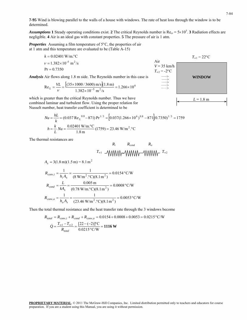
PROPRIETARY MATERIAL. © 2011 The McGraw-Hill Companies, Inc. Limited distribution permitted only to teachers and educators for course preparation. If you are a student using this Manual, you are using it without permission.
7-84
7-95 Wind is blowing parallel to the walls of a house with windows. The rate of heat loss through the window is to be determined.
Assumptions 1 Steady operating conditions exist. 2 The critical Reynolds number is Recr = 5×10⁵. 3 Radiation effects are negligible. 4 Air is an ideal gas with constant properties. 5 The pressure of air is 1 atm.
Properties Assuming a film temperature of 5°C, the properties of air at 1 atm and this temperature are evaluated to be (Table A-15)
7350.0Pr
/sm 10382.1
C W/m.02401.025-
=×=
°=
ν
k
WINDOW
Air V = 35 km/h T∞2 = -2°C
T∞1 = 22°C
Analysis Air flows along 1.8 m side. The Reynolds number in this case is
[ ] 6
2510266.1
/sm 10382.1m) (1.8m/s )3600/100035(
Re ×=×
×==
−νVL
L
which is greater than the critical Reynolds number. Thus we have combined laminar and turbulent flow. Using the proper relation for Nusselt number, heat transfer coefficient is determined to be
L = 1.8 m
[ ]
C. W/m46.23)1759(m 8.1
C W/m.02401.0
1759)7350.0(871)10266.1(037.0Pr)871Re037.0(
2
3/18.063/18.0
°=°
==
=−×=−==
NuLkh
khLNu L
The thermal resistances are Ri Rcond Ro
T∞1 T∞2
2m 8.1=m) m)(1.5 8.1(3=sA
C/W 0053.0)m C)(8.1. W/m46.23(
11
C/W 0008.0)m C)(8.1 W/m.(0.78
m 005.0
C/W 0154.0)m C)(8.1. W/m8(
11
22,
2
22,
°=°
==
°=°
==
°=°
==
sooconv
scond
siiconv
AhR
kALR
AhR
Then the total thermal resistance and the heat transfer rate through the 3 windows become
W1116=
°°−−
=−
=
°=++=++=
∞∞
C/W 0215.0C)]2(22[
C/W 0215.00053.00008.00154.0
21
,,
total
oconvcondiconvtotal
RTT
Q
RRRR
&
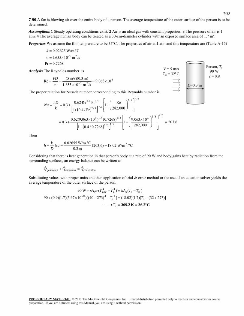
PROPRIETARY MATERIAL. © 2011 The McGraw-Hill Companies, Inc. Limited distribution permitted only to teachers and educators for course preparation. If you are a student using this Manual, you are using it without permission.
7-85
7-96 A fan is blowing air over the entire body of a person. The average temperature of the outer surface of the person is to be determined.
Assumptions 1 Steady operating conditions exist. 2 Air is an ideal gas with constant properties. 3 The pressure of air is 1 atm. 4 The average human body can be treated as a 30-cm-diameter cylinder with an exposed surface area of 1.7 m2.
Properties We assume the film temperature to be 35°C. The properties of air at 1 atm and this temperature are (Table A-15)
7268.0Pr
/sm 10655.1
C W/m.02625.025-
=×=
°=
ν
k
D=0.3 m
Person, T90 W
s
ε = 0.9
V = 5 m/s T∞ = 32°C
Analysis The Reynolds number is
425
10063.9/sm 10655.1
m) m/s)(0.3 (5Re ×=
×==
−νVD
The proper relation for Nusselt number corresponding to this Reynolds number is
( )[ ]
( )[ ] 6.203000,282
10063.917268.0/4.01
)7268.0()10063.9(62.03.0
000,282Re1
Pr/4.01
PrRe62.03.0
5/48/54
4/13/2
3/15.04
5/48/5
4/13/2
3/15.0
=⎥⎥
⎦
⎤
⎢⎢
⎣
⎡
⎟⎟⎠
⎞⎜⎜⎝
⎛ ×+
+
×+=
⎥⎥⎦
⎤
⎢⎢⎣
⎡⎟⎟⎠
⎞⎜⎜⎝
⎛+
++==
khDNu
Then
C. W/m02.18)6.203(m 3.0
C W/m.02655.0 2 °=°
== NuDkh
Considering that there is heat generation in that person's body at a rate of 90 W and body gains heat by radiation from the surrounding surfaces, an energy balance can be written as
convectionradiationgenerated QQQ &&& =+
Substituting values with proper units and then application of trial & error method or the use of an equation solver yields the average temperature of the outer surface of the person.
C36.2K 309.2 °==⎯→⎯
+−=−+×+
−=−+−
∞
s
ss
ssssurrs
T
TT
TThATTA
)]27332()[7.1)(02.18(])27340)[(1067.5)(7.1)(9.0(90
)()( W90448
44σε
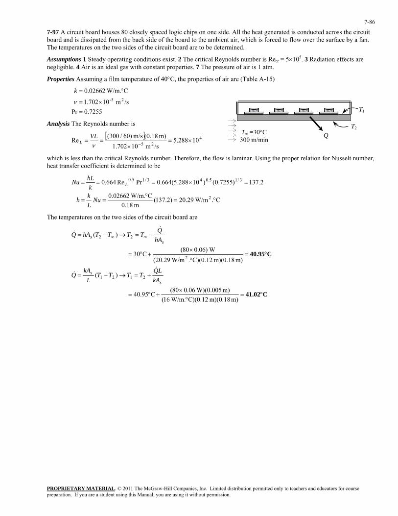
PROPRIETARY MATERIAL. © 2011 The McGraw-Hill Companies, Inc. Limited distribution permitted only to teachers and educators for course preparation. If you are a student using this Manual, you are using it without permission.
7-86
7-97 A circuit board houses 80 closely spaced logic chips on one side. All the heat generated is conducted across the circuit board and is dissipated from the back side of the board to the ambient air, which is forced to flow over the surface by a fan. The temperatures on the two sides of the circuit board are to be determined.
Assumptions 1 Steady operating conditions exist. 2 The critical Reynolds number is Recr = 5×10⁵. 3 Radiation effects are negligible. 4 Air is an ideal gas with constant properties. 7 The pressure of air is 1 atm.
Properties Assuming a film temperature of 40°C, the properties of air are (Table A-15)
7255.0Pr
/sm 10702.1
C W/m.02662.025-
=×=
°=
ν
k
QT∞ =30°C 300 m/min
T2
T1
Analysis The Reynolds number is
[ ] 425
10288.5/sm 10702.1
m) (0.18m/s )60/300(Re ×=
×==
−νVL
L
which is less than the critical Reynolds number. Therefore, the flow is laminar. Using the proper relation for Nusselt number, heat transfer coefficient is determined to be
C. W/m29.20)2.137(
m 18.0C W/m.02662.0
2.137)7255.0()10288.5(664.0PrRe664.0
2
3/15.043/15.0
°=°
==
=×===
NuLkh
khLNu L
The temperatures on the two sides of the circuit board are
C41.02
C40.95
°=°
×+°=
+=→−=
°=°
×+°=
+=→−= ∞∞
m) m)(0.18 C)(0.12 W/m.16(m) W)(0.00506.080(
C95.40
)(
m) m)(0.18 C)(0.12. W/m29.20( W)06.080(
C30
)(
2121
2
22
s
s
ss
kALQ
TTTTL
kAQ
hAQTTTThAQ
&&
&&

PROPRIETARY MATERIAL. © 2011 The McGraw-Hill Companies, Inc. Limited distribution permitted only to teachers and educators for course preparation. If you are a student using this Manual, you are using it without permission.
7-87
7-98 A spherical tank used to store iced water is subjected to winds. The rate of heat transfer to the iced water and the amount of ice that melts during a 24-h period are to be determined.
Assumptions 1 Steady operating conditions exist. 2 Thermal resistance of the tank is negligible. 3 Radiation effects are negligible. 4 Air is an ideal gas with constant properties. 5 The pressure of air is 1 atm.
Properties The properties of air at 1 atm pressure and the free stream temperature of 30°C are (Table A-15)
7282.0Pr
kg/m.s 10729.1
kg/m.s 10872.1
/sm 10608.1
C W/m.02588.0
5C0@,
5
25-
=
×=
×=
×=
°=
−°
−∞
s
k
µ
µ
ν
Di = 3 m Iced water
0°C Q&
V = 25 km/h T∞ = 30°C
1 cm
Ts = 0°C
Analysis (a) The Reynolds number is
[ ] 625
10304.1/sm 10608.1
m) (3.02m/s 1000/3600)(25Re ×=
×
×==
−νVD
The Nusselt number corresponding to this Reynolds number is determined from
[ ]
[ ] 105610729.110872.1)7282.0()10304.1(06.0)10304.1(4.02
PrRe06.0Re4.02
4/1
5
54.03/265.06
4/14.03/25.0
=⎟⎟⎠
⎞⎜⎜⎝
⎛
×
××+×+=
⎟⎟⎠
⎞⎜⎜⎝
⎛++==
−
−
∞
skhDNu
µµ
and C. W/m05.9)1056(m 02.3
C W/m.02588.0 2 °=°
== NuDkh
The rate of heat transfer to the iced water is
W7779=°−°=−=−= ∞∞ C)030(]m) (3.02C)[. W/m05.9())(()( 222 ππ TTDhTThAQ sss&
(b) The amount of heat transfer during a 24-hour period is
kJ 000,672s) 3600kJ/s)(24 779.7( =×=∆= tQQ &
Then the amount of ice that melts during this period becomes
kg 2014===⎯→⎯=kJ/kg 7.333
kJ 000,672
ifif h
QmmhQ
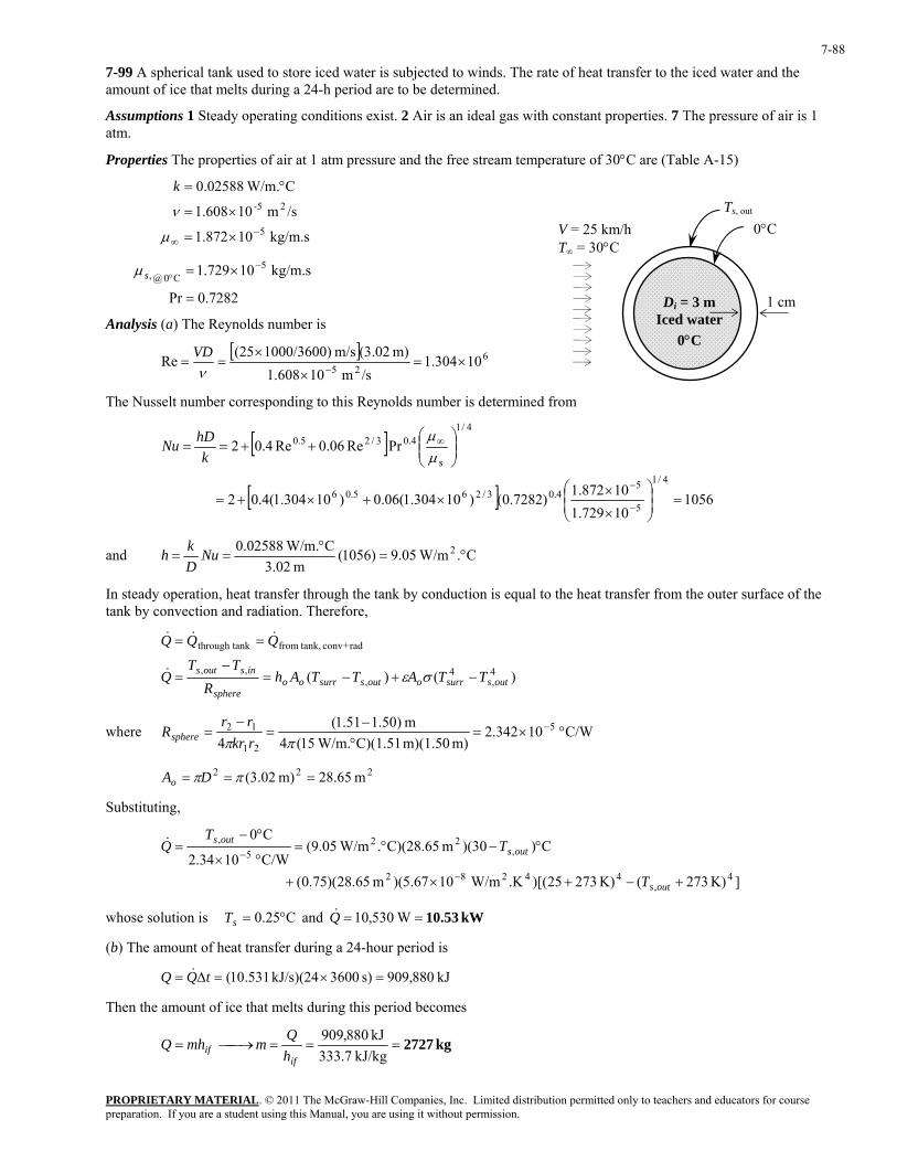
PROPRIETARY MATERIAL. © 2011 The McGraw-Hill Companies, Inc. Limited distribution permitted only to teachers and educators for course preparation. If you are a student using this Manual, you are using it without permission.
7-88
7-99 A spherical tank used to store iced water is subjected to winds. The rate of heat transfer to the iced water and the amount of ice that melts during a 24-h period are to be determined.
Assumptions 1 Steady operating conditions exist. 2 Air is an ideal gas with constant properties. 7 The pressure of air is 1 atm.
Properties The properties of air at 1 atm pressure and the free stream temperature of 30°C are (Table A-15)
kg/m.s 10872.1
/sm 10608.1
C W/m.02588.0
5
25-
−∞ ×=
×=
°=
µ
ν
k
Di = 3 m Iced water
0°C
Ts, out V = 25 km/h T∞ = 30°C
1 cm
0°C
7282.0Pr
kg/m.s 10729.1 5C0@,
=
×= −°sµ
Analysis (a) The Reynolds number is
[ ] 6
2510304.1
/sm 10608.1m) (3.02m/s 1000/3600)(25
Re ×=×
×==
−νVD
The Nusselt number corresponding to this Reynolds number is determined from
[ ]
[ ] 105610729.110872.1)7282.0()10304.1(06.0)10304.1(4.02
PrRe06.0Re4.02
4/1
5
54.03/265.06
4/14.03/25.0
=⎟⎟⎠
⎞⎜⎜⎝
⎛
×
××+×+=
⎟⎟⎠
⎞⎜⎜⎝
⎛++==
−
−
∞
skhDNu
µµ
and C. W/m05.9)1056(m 02.3
C W/m.02588.0 2 °=°
== NuDkh
In steady operation, heat transfer through the tank by conduction is equal to the heat transfer from the outer surface of the tank by convection and radiation. Therefore,
)()( 4
,4
,,,
rad+conv tank,fromnkthrough ta
outssurrooutssurroosphere
insouts TTATTAhR
TTQ
QQQ
−+−=−
=
==
σε&
&&&
where C/W 10342.2m) m)(1.50 C)(1.51 W/m.15(4
m )50.151.1(4
5
21
12 °×=°−
=−
= −
ππ rkrrr
Rsphere
222 m 28.65m) 02.3( === ππDAo
Substituting,
]K) 273(K) 27325)[(.K W/m1067.5)(m 65.28)(75.0(
C))(30m C)(28.65. W/m05.9(C/W 1034.2
C0
4,
44282
,22
5,
+−+×+
°−°=°×
°−=
−
−
outs
outsouts
T
TT
Q&
whose solution is T kW 10.53==°= W530,10 and C25.0 Qs&
(b) The amount of heat transfer during a 24-hour period is
kJ 880,909s) 3600kJ/s)(24 531.10( =×=∆= tQQ &
Then the amount of ice that melts during this period becomes
kg 2727===⎯→⎯=kJ/kg 7.333
kJ 880,909
ifif h
QmmhQ
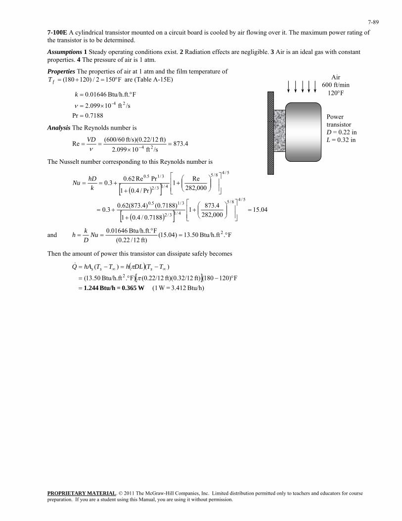
PROPRIETARY MATERIAL. © 2011 The McGraw-Hill Companies, Inc. Limited distribution permitted only to teachers and educators for course preparation. If you are a student using this Manual, you are using it without permission.
7-89
7-100E A cylindrical transistor mounted on a circuit board is cooled by air flowing over it. The maximum power rating of the transistor is to be determined.
Assumptions 1 Steady operating conditions exist. 2 Radiation effects are negligible. 3 Air is an ideal gas with constant properties. 4 The pressure of air is 1 atm.
Properties The properties of air at 1 atm and the film temperature of are (Table A-15E) F1502/)120180( °=+=fT
7188.0Pr
/sft 10099.2
FBtu/h.ft. 01646.024-
=×=
°=
ν
k
Analysis The Reynolds number is
4.873/sft 10099.2
ft) /12ft/s)(0.22 (600/60Re 24 =×
==−ν
VD
The Nusselt number corresponding to this Reynolds number is
( )[ ]
( )[ ] 04.15000,2824.8731
7188.0/4.01
)7188.0()4.873(62.03.0
000,282Re1
Pr/4.01
PrRe62.03.0
5/48/5
4/13/2
3/15.0
5/48/5
4/13/2
3/15.0
=⎥⎥⎦
⎤
⎢⎢⎣
⎡⎟⎟⎠
⎞⎜⎜⎝
⎛+
++=
⎥⎥⎦
⎤
⎢⎢⎣
⎡⎟⎟⎠
⎞⎜⎜⎝
⎛+
++==
khDNu
Air 600 ft/min
120°F
Power transistor D = 0.22 inL = 0.32 in
and F.Btu/h.ft 50.13)04.15(ft) 12/22.0(
FBtu/h.ft. 01646.0 2 °=°
== NuDkh
Then the amount of power this transistor can dissipate safely becomes
( )[ ]
Btu/h) 3.412 = W (1F)120180(ft) 2ft)(0.32/1 (0.22/12F).Btu/h.ft 50.13(
)()(2
W0.365 = Btu/h 1.244=°−°=
−=−= ∞∞
π
π TTDLhTThAQ sss&
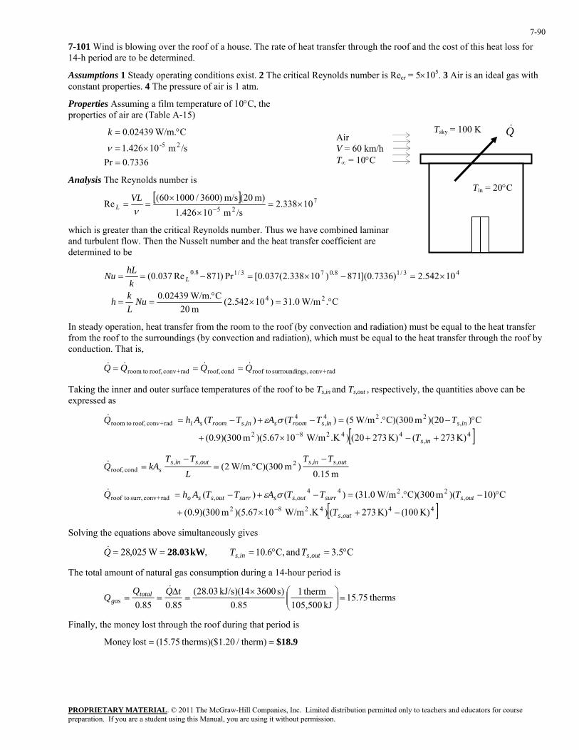
PROPRIETARY MATERIAL. © 2011 The McGraw-Hill Companies, Inc. Limited distribution permitted only to teachers and educators for course preparation. If you are a student using this Manual, you are using it without permission.
7-90
7-101 Wind is blowing over the roof of a house. The rate of heat transfer through the roof and the cost of this heat loss for 14-h period are to be determined.
Assumptions 1 Steady operating conditions exist. 2 The critical Reynolds number is Recr = 5×10⁵. 3 Air is an ideal gas with constant properties. 4 The pressure of air is 1 atm.
Properties Assuming a film temperature of 10°C, the properties of air are (Table A-15)
Tin = 20°C
Tsky = 100 K Q&
7336.0Pr/sm 10426.1
C W/m.02439.025-
=×=
°=
ν
k Air V = 60 km/h T∞ = 10°C
Analysis The Reynolds number is
[ ] 7
2510338.2
/sm 10426.1m) (20m/s )3600/100060(
Re ×=×
×==
−νVL
L
which is greater than the critical Reynolds number. Thus we have combined laminar and turbulent flow. Then the Nusselt number and the heat transfer coefficient are determined to be
C. W/m0.31)10542.2(m 20
C W/m.02439.0
10542.2)7336.0](871)10338.2(037.0[Pr)871Re037.0(
24
43/18.073/18.0
°=×°
==
×=−×=−==
NuLkh
khLNu L
In steady operation, heat transfer from the room to the roof (by convection and radiation) must be equal to the heat transfer from the roof to the surroundings (by convection and radiation), which must be equal to the heat transfer through the roof by conduction. That is,
rad+conv gs,surroundin toroofcond roof,rad+conv roof, toroom QQQQ &&&& ===
Taking the inner and outer surface temperatures of the roof to be Ts,in and Ts,out , respectively, the quantities above can be expressed as
[ ]4,
44282
,224
,4
, rad+conv roof, toroom
K) 273(K) 27320().K W/m1067.5)(m 300)(9.0(
C))(20m C)(300. W/m5()()(
+−+×+
°−°=−+−=−
ins
insinsroomsinsroomsi
T
TTTATTAhQ σε&
m 15.0)m 300)(C W/m.2( ,,2,,
cond roof,outsinsoutsins
sTT
LTT
kAQ−
°=−
=&
[ ]44,
4282
,2244
,, rad+conv surr, toroof
K) 100(K) 273().K W/m1067.5)(m 300)(9.0(
C)10)(m C)(300. W/m0.31()()(
−+×+
°−°=−+−=−
outs
outssurroutsssurroutsso
T
TTTATTAhQ σε&
Solving the equations above simultaneously gives
C5.3and C,6.10 , W025,28 ,, °=°=== outsins TTQ kW 28.03&
The total amount of natural gas consumption during a 14-hour period is
therms75.15kJ 105,500
therm185.0
)s 360014)(kJ/s 03.28(85.085.0
=⎟⎟⎠
⎞⎜⎜⎝
⎛×=
∆==
tQQQ total
gas
&
Finally, the money lost through the roof during that period is
$18.9== )therm/20.1$ therms)(75.15(lostMoney
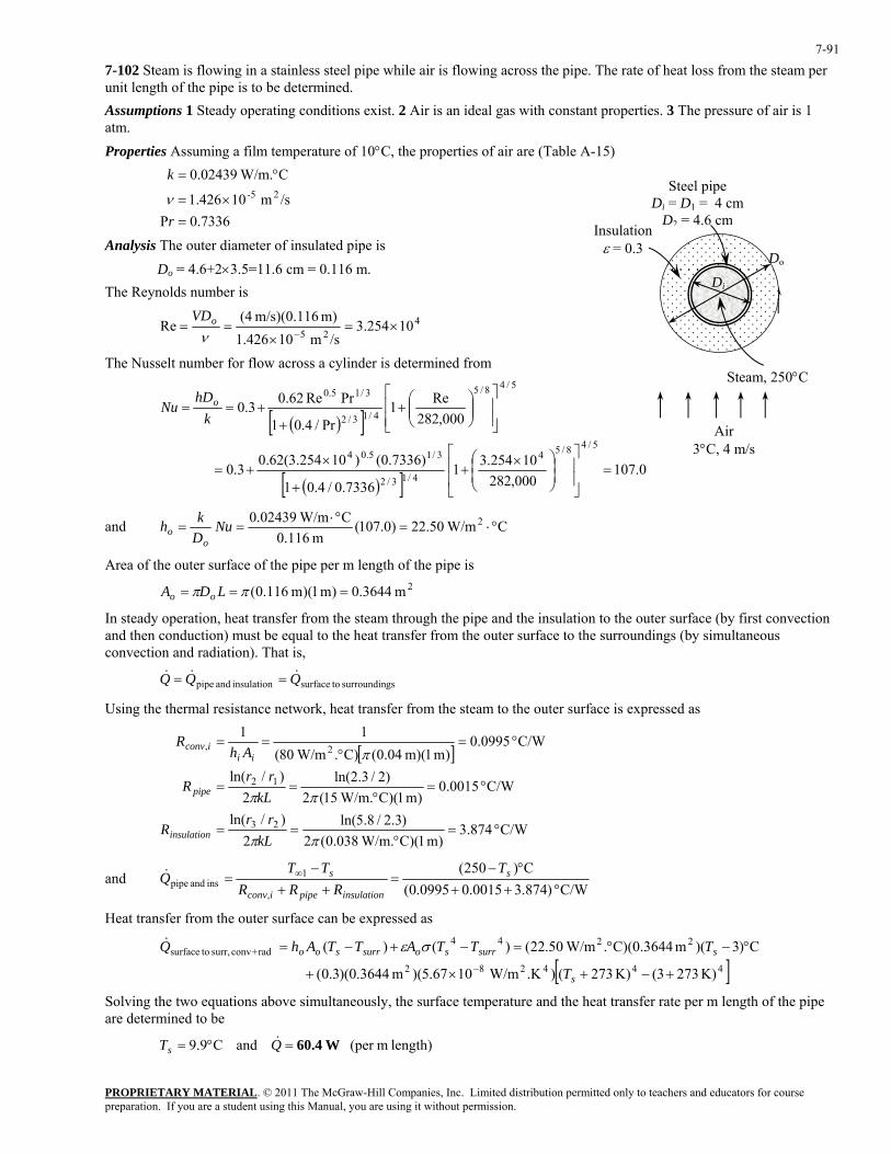
PROPRIETARY MATERIAL. © 2011 The McGraw-Hill Companies, Inc. Limited distribution permitted only to teachers and educators for course preparation. If you are a student using this Manual, you are using it without permission.
7-91
7-102 Steam is flowing in a stainless steel pipe while air is flowing across the pipe. The rate of heat loss from the steam per unit length of the pipe is to be determined. Assumptions 1 Steady operating conditions exist. 2 Air is an ideal gas with constant properties. 3 The pressure of air is 1 atm. Properties Assuming a film temperature of 10°C, the properties of air are (Table A-15)
7336.0P
/sm 10426.1
C W/m.02439.025-
=×=
°=
r
k
νSteel pipe
Di = D1 = 4 cm D2 = 4.6 cm
Insulation ε = 0.3
Di
DoAnalysis The outer diameter of insulated pipe is
Do = 4.6+2×3.5=11.6 cm = 0.116 m. The Reynolds number is
425
10254.3/sm 10426.1
m) m/s)(0.116 (4Re ×=
×==
−νoVD
The Nusselt number for flow across a cylinder is determined from Steam, 250°C
( )[ ]
( )[ ] 0.107000,282
10254.317336.0/4.01
)7336.0()10254.3(62.03.0
000,282Re1
Pr/4.01
PrRe62.03.0
5/48/54
4/13/2
3/15.04
5/48/5
4/13/2
3/15.0
=⎥⎥
⎦
⎤
⎢⎢
⎣
⎡
⎟⎟⎠
⎞⎜⎜⎝
⎛ ×+
+
×+=
⎥⎥⎦
⎤
⎢⎢⎣
⎡⎟⎟⎠
⎞⎜⎜⎝
⎛+
++==
khD
Nu o
Air 3°C, 4 m/s
and C W/m50.22)0.107(m 116.0
C W/m0.02439 2 °⋅=°⋅
== NuDkh
oo
Area of the outer surface of the pipe per m length of the pipe is
2m 3644.0)m 1)(m 116.0( === ππ LDA oo
In steady operation, heat transfer from the steam through the pipe and the insulation to the outer surface (by first convection and then conduction) must be equal to the heat transfer from the outer surface to the surroundings (by simultaneous convection and radiation). That is,
gssurroundin tosurfaceinsulation and pipe QQQ &&& ==
Using the thermal resistance network, heat transfer from the steam to the outer surface is expressed as
[ ]
C/W 874.3)m 1)(C W/m.038.0(2
)3.2/8.5ln(2
)/ln(
C/W 0015.0)m 1)(C W/m.15(2
)2/3.2ln(2
)/ln(
C/W 0995.0)m 1(m) 04.0()C. W/m80(
11
23
12
2,
°=°
==
°=°
==
°=°
==
ππ
ππ
π
kLrr
R
kLrr
R
AhR
insulation
pipe
iiiconv
and C/W )874.30015.00995.0(
C)250(
,
1ins and pipe °++
°−=
++−
= ∞ s
insulationpipeiconv
s TRRR
TTQ&
Heat transfer from the outer surface can be expressed as
[ ]444282
2244 rad+conv surr, tosurface
K) 2733(K) 273().K W/m1067.5)(m 3644.0)(3.0(
C)3)(m C)(0.3644. W/m50.22()()(
+−+×+
°−°=−+−=−
s
ssurrsosurrsoo
T
TTTATTAhQ σε&
Solving the two equations above simultaneously, the surface temperature and the heat transfer rate per m length of the pipe are determined to be
length) m(per and C9.9 W60.4=°= QTs&
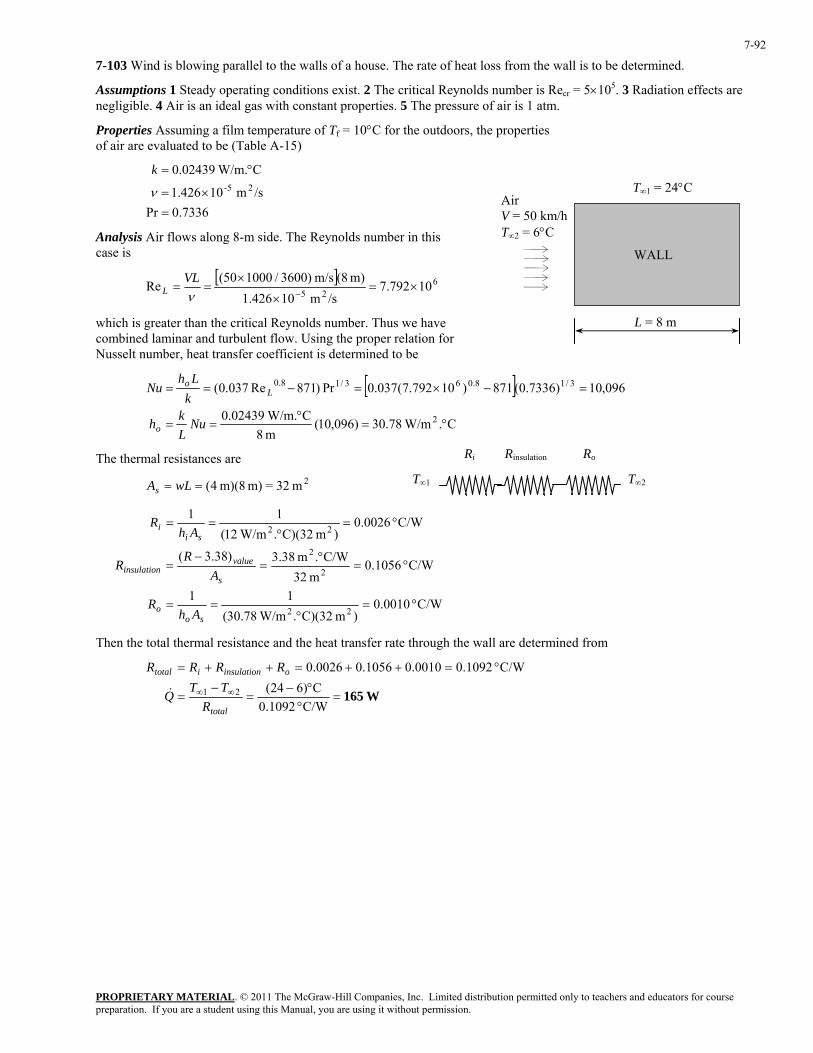
PROPRIETARY MATERIAL. © 2011 The McGraw-Hill Companies, Inc. Limited distribution permitted only to teachers and educators for course preparation. If you are a student using this Manual, you are using it without permission.
7-92
7-103 Wind is blowing parallel to the walls of a house. The rate of heat loss from the wall is to be determined.
Assumptions 1 Steady operating conditions exist. 2 The critical Reynolds number is Recr = 5×10⁵. 3 Radiation effects are negligible. 4 Air is an ideal gas with constant properties. 5 The pressure of air is 1 atm.
Properties Assuming a film temperature of Tf = 10°C for the outdoors, the properties of air are evaluated to be (Table A-15)
7336.0Pr
/sm 10426.1
C W/m.02439.025-
=×=
°=
ν
k
WALL
Air V = 50 km/h T∞2 = 6°C
T∞1 = 24°C
Analysis Air flows along 8-m side. The Reynolds number in this case is
[ ] 625
10792.7/sm 10426.1
m) (8m/s )3600/100050(Re ×=
×
×==
−νVL
L
L = 8 mwhich is greater than the critical Reynolds number. Thus we have combined laminar and turbulent flow. Using the proper relation for Nusselt number, heat transfer coefficient is determined to be
[ ]
C. W/m78.30)096,10(m 8
C W/m.02439.0
096,10)7336.0(871)10792.7(037.0Pr)871Re037.0(
2
3/18.063/18.0
°=°
==
=−×=−==
NuLkh
kLh
Nu
o
Lo
Ri Rinsulation Ro The thermal resistances are T∞1 T∞2 2m 32=m) m)(8 4(== wLAs
C/W 0010.0)m C)(32. W/m78.30(
11
C/W 1056.0m 32
C/W.m 38.3)38.3(
C/W 0026.0)m C)(32. W/m12(
11
22
2
2
22
°=°
==
°=°
=−
=
°=°
==
soo
s
valueinsulation
sii
AhR
AR
R
AhR
Then the total thermal resistance and the heat transfer rate through the wall are determined from
W165=
°°−
=−
=
°=++=++=
∞∞
C/W 1092.0C)624(
C/W 1092.00010.01056.00026.0
21
total
oinsulationitotal
RTT
Q
RRRR
&
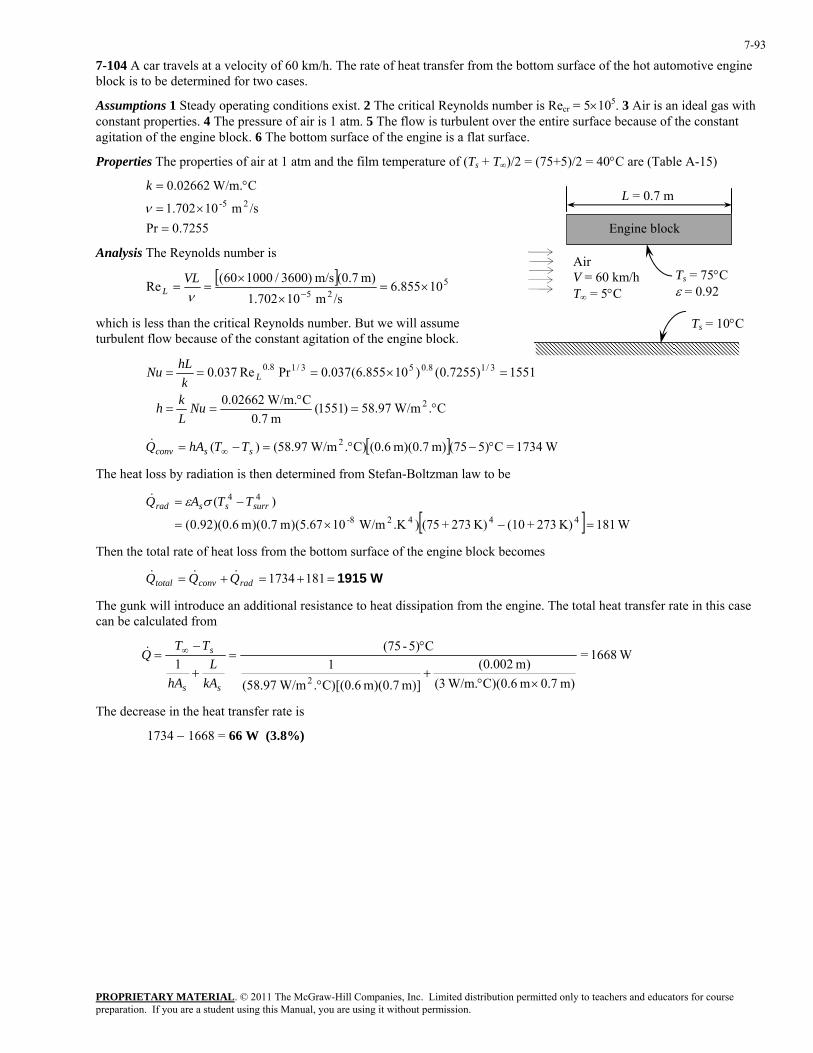
PROPRIETARY MATERIAL. © 2011 The McGraw-Hill Companies, Inc. Limited distribution permitted only to teachers and educators for course preparation. If you are a student using this Manual, you are using it without permission.
7-93
7-104 A car travels at a velocity of 60 km/h. The rate of heat transfer from the bottom surface of the hot automotive engine block is to be determined for two cases.
Assumptions 1 Steady operating conditions exist. 2 The critical Reynolds number is Recr = 5×10⁵. 3 Air is an ideal gas with constant properties. 4 The pressure of air is 1 atm. 5 The flow is turbulent over the entire surface because of the constant agitation of the engine block. 6 The bottom surface of the engine is a flat surface.
Properties The properties of air at 1 atm and the film temperature of (Ts + T∞)/2 = (75+5)/2 = 40°C are (Table A-15)
7255.0Pr
/sm 10702.1
C W/m.02662.025-
=×=
°=
ν
kL = 0.7 m
Ts = 75°C ε = 0.92
Engine block
Air V = 60 km/h T∞ = 5°C
Analysis The Reynolds number is
[ ] 525
10855.6/sm 10702.1
m) (0.7m/s )3600/100060(Re ×=
×
×==
−νVL
L
which is less than the critical Reynolds number. But we will assume turbulent flow because of the constant agitation of the engine block.
C. W/m97.58)1551(
m 7.0C W/m.02662.0
1551)7255.0()10855.6(037.0PrRe037.0
2
3/18.053/18.0
°=°
==
=×===
NuLkh
khLNu L
Ts = 10°C
[ ] W1734=C5)(75m) m)(0.7 (0.6C). W/m97.58()( 2 °−°=−= ∞ ssconv TThAQ&
The heat loss by radiation is then determined from Stefan-Boltzman law to be
[ ] W181K) 273+(10K) 273+(75).K W/m10(5.67)m 7.0)(m 6.0)(92.0(
)(44428-
44
=−×=
−= surrssrad TTAQ σε&
Then the total rate of heat loss from the bottom surface of the engine block becomes
W1915=+=+= 1811734radconvtotal QQQ &&&
The gunk will introduce an additional resistance to heat dissipation from the engine. The total heat transfer rate in this case can be calculated from
W1668=
m) 0.7m 6.0)(C W/m.3()m 002.0(
m)] m)(0.7 C)[(0.6. W/m97.58(1
C5)-(751
2 ×°+
°
°=
+
−= ∞
ss
s
kAL
hA
TTQ&
The decrease in the heat transfer rate is
1734 − 1668 = 66 W (3.8%)
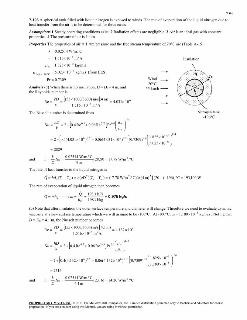
PROPRIETARY MATERIAL. © 2011 The McGraw-Hill Companies, Inc. Limited distribution permitted only to teachers and educators for course preparation. If you are a student using this Manual, you are using it without permission.
7-94
7-105 A spherical tank filled with liquid nitrogen is exposed to winds. The rate of evaporation of the liquid nitrogen due to heat transfer from the air is to be determined for three cases.
Assumptions 1 Steady operating conditions exist. 2 Radiation effects are negligible. 3 Air is an ideal gas with constant properties. 4 The pressure of air is 1 atm.
Properties The properties of air at 1 atm pressure and the free stream temperature of 20°C are (Table A-15)
7309.0Pr
EES) (from kg/m.s 10023.5
kg/m.s 10825.1
/sm 10516.1
C W/m.02514.0
6C 196@,
5
25-
=
×=
×=
×=
°=
−°−
−∞
s
k
µ
µ
ν Insulation
Analysis (a) When there is no insulation, D = Di = 4 m, and the Reynolds number is
[ ] 625 10031.4/sm 10516.1
m) (4m/s 1000/3600)(55Re ×=×
×==
−νVD
The Nusselt number is determined from
[ ]
[ ]2829
10023.510825.1)7309.0()10031.4(06.0)10031.4(4.02
PrRe06.0Re4.02
4/1
6
54.03/265.06
4/14.03/25.0
=
⎟⎟⎠
⎞⎜⎜⎝
⎛
×
××+×+=
⎟⎟⎠
⎞⎜⎜⎝
⎛++==
−
−
∞
skhDNu
µµ
Nitrogen tank -196°C
Di
DoWind 20°C
55 km/h
and C. W/m78.17)2829(m 4
C W/m.02514.0 2 °=°
== NuDkh
The rate of heat transfer to the liquid nitrogen is
[ ] W100,193C )196(20(]m) (4C)[. W/m78.17())(()( 222 =°−−°=−=−= ∞∞ ππ TTDhTThAQ sss&
The rate of evaporation of liquid nitrogen then becomes
kg/s 0.975===⎯→⎯=kJ/kg 198
kJ/s 1.193
ifif h
QmhmQ&
&&&
(b) Note that after insulation the outer surface temperature and diameter will change. Therefore we need to evaluate dynamic viscosity at a new surface temperature which we will assume to be -100°C. At -100°C, . Noting that D = D
kg/m.s 10189.1 5−×=µ0 = 4.1 m, the Nusselt number becomes
[ ] 625 10132.4/sm 10516.1
m) (4.1m/s 1000/3600)(55Re ×=×
×==
−νVD
[ ]
[ ]2316
10189.110825.1)7309.0()10132.4(06.0)10132.4(4.02
PrRe06.0Re4.02
4/1
5
54.03/265.06
4/14.03/25.0
=
⎟⎟⎠
⎞⎜⎜⎝
⎛
×
××+×+=
⎟⎟⎠
⎞⎜⎜⎝
⎛++==
−
−
∞
skhDNu
µµ
and C. W/m20.14)2316(m 1.4
C W/m.02514.0 2 °=°
== NuDkh
PROPRIETARY MATERIAL. © 2011 The McGraw-Hill Companies, Inc. Limited distribution permitted only to teachers and educators for course preparation. If you are a student using this Manual, you are using it without permission.
7-95
The rate of heat transfer to the liquid nitrogen is
W7433
)m 81.52)(C. W/m20.14(1
m) m)(2 C)(2.05 W/m.(0.0354m )205.2(
C)]196(20[
14
m 81.52)m 1.4(
22
21
12
tan,tan,
222
=
°+
°−
°−−=
+−−
=+
−=
===
∞∞
π
π
ππ
s
ks
convinsulation
ks
s
hArkrrr
TTRR
TTQ
DA
&
The rate of evaporation of liquid nitrogen then becomes
kg/s 0.0375===⎯→⎯=kJ/kg 198
kJ/s 433.7
ifif h
QmhmQ&
&&&
(c) We use the dynamic viscosity value at the new estimated surface temperature of 0°C to be . Noting that D = D
kg/m.s 10729.1 5−×=µ0 = 4.04 m in this case, the Nusselt number becomes
[ ] 625 10071.4/sm 10516.1
m) (4.04m/s 1000/3600)(55Re ×=×
×==
−νVD
[ ]
[ ]2090
10729.110825.1)7309.0()10071.4(06.0)10071.4(4.02
PrRe06.0Re4.02
4/1
5
54.03/265.06
4/14.03/25.0
=
⎟⎟⎠
⎞⎜⎜⎝
⎛
×
××+×+=
⎟⎟⎠
⎞⎜⎜⎝
⎛++==
−
−
∞
skhDNu
µµ
and C. W/m01.13)2090(m 04.4
C W/m.02514.0 2 °=°
== NuDkh
The rate of heat transfer to the liquid nitrogen is
W41.27
)m 28.51)(C. W/m01.13(1
m) m)(2 C)(2.02 W/m.(0.000054m )202.2(
C)]196(20[
14
m 28.51)m 04.4(
22
21
12
tan,tan,
222
=
°+
°−
°−−=
+−−
=+
−=
===
∞∞
π
π
ππ
s
ks
convinsulation
ks
s
hArkrrr
TTRR
TTQ
DA
&
The rate of evaporation of liquid nitrogen then becomes
kg/s 101.38 4-×===⎯→⎯=kJ/kg 198
kJ/s 02741.0
ifif h
QmhmQ&
&&&

PROPRIETARY MATERIAL. © 2011 The McGraw-Hill Companies, Inc. Limited distribution permitted only to teachers and educators for course preparation. If you are a student using this Manual, you are using it without permission.
7-96
7-106 A spherical tank filled with liquid oxygen is exposed to ambient winds. The rate of evaporation of the liquid oxygen due to heat transfer from the air is to be determined for three cases.
Assumptions 1 Steady operating conditions exist. 2 Radiation effects are negligible. 3 Air is an ideal gas with constant properties. 7 The pressure of air is 1 atm.
Properties The properties of air at 1 atm pressure and the free stream temperature of 20°C are (Table A-15)
7309.0Pr
EES) (from kg/m.s 10127.6
kg/m.s 10825.1
/sm 10516.1
C W/m.02514.0
6C183@,
5
25-
=
×=
×=
×=
°=
−°−
−∞
s
k
µ
µ
ν Insulation
Analysis (a) When there is no insulation, D = Di = 4 m, and the Reynolds number is
[ ] 625 10031.4/sm 10516.1
m) (4m/s 1000/3600)(55Re ×=×
×==
−νVD
The Nusselt number is determined from
[ ]
[ ]2692
10127.610825.1)7309.0()10031.4(06.0)10031.4(4.02
PrRe06.0Re4.02
4/1
6
54.03/265.06
4/14.03/25.0
=
⎟⎟⎠
⎞⎜⎜⎝
⎛
×
××+×+=
⎟⎟⎠
⎞⎜⎜⎝
⎛++==
−
−
∞
skhDNu
µµ
Oxygen tank -183°C
Di
DoWind 20°C
55 km/h
and C. W/m92.16)2692(m 4
C W/m.02514.0 2 °=°
== NuDkh
The rate of heat transfer to the liquid oxygen is
[ ] W600,172C )183(20(]m) (4C)[. W/m92.16())(()( 222 =°−−°=−=−= ∞∞ ππ TTDhTThAQ sss&
The rate of evaporation of liquid oxygen then becomes
kg/s 0.811===⎯→⎯=kJ/kg 213
kJ/s 6.172
ifif h
QmhmQ&
&&&
(b) Note that after insulation the outer surface temperature and diameter will change. Therefore we need to evaluate dynamic viscosity at a new surface temperature which we will assume to be -100°C. At -100°C, . Noting that D = D
kg/m.s 10189.1 5−×=µ0 = 4.1 m, the Nusselt number becomes
[ ] 625 10132.4/sm 10516.1
m) (4.1m/s 1000/3600)(55Re ×=×
×==
−νVD
[ ]
[ ]2316
10189.110825.1)7309.0()10132.4(06.0)10132.4(4.02
PrRe06.0Re4.02
4/1
5
54.03/265.06
4/14.03/25.0
=
⎟⎟⎠
⎞⎜⎜⎝
⎛
×
××+×+=
⎟⎟⎠
⎞⎜⎜⎝
⎛++==
−
−
∞
skhDNu
µµ
and C. W/m20.14)2316(m 1.4
C W/m.02514.0 2 °=°
== NuDkh
PROPRIETARY MATERIAL. © 2011 The McGraw-Hill Companies, Inc. Limited distribution permitted only to teachers and educators for course preparation. If you are a student using this Manual, you are using it without permission.
7-97
The rate of heat transfer to the liquid nitrogen is
W6985
)m 81.52)(C. W/m20.14(1
m) m)(2 C)(2.05 W/m.(0.0354m )205.2(
C)]183(20[
14
m 81.52)m 1.4(
22
21
12
tan,tan,
222
=
°+
°−
°−−=
+−−
=+
−=
===
∞∞
π
π
ππ
s
ks
convinsulation
ks
s
hArkrrr
TTRR
TTQ
DA
&
The rate of evaporation of liquid nitrogen then becomes
kg/s 0.0328===⎯→⎯=kJ/kg 213
kJ/s 985.6
ifif h
QmhmQ&
&&&
(c) Again we use the dynamic viscosity value at the estimated surface temperature of 0°C to be . Noting that D = D
kg/m.s 10729.1 5−×=µ0 = 4.04 m in this case, the Nusselt number becomes
[ ] 625 10071.4/sm 10516.1
m) (4.04m/s 1000/3600)(55Re ×=×
×==
−νVD
[ ]
[ ]2090
10729.110825.1)7309.0()10071.4(06.0)10071.4(4.02
PrRe06.0Re4.02
4/1
5
54.03/265.06
4/14.03/25.0
=
⎟⎟⎠
⎞⎜⎜⎝
⎛
×
××+×+=
⎟⎟⎠
⎞⎜⎜⎝
⎛++==
−
−
∞
skhDNu
µµ
and C. W/m01.13)2090(m 04.4
C W/m.02514.0 2 °=°
== NuDkh
The rate of heat transfer to the liquid nitrogen is
W76.25
)m 28.51)(C. W/m01.13(1
m) m)(2 C)(2.02 W/m.(0.000054m )202.2(
C)]183(20[
14
m 28.51)m 04.4(
22
21
12
tan,tan,
222
=
°+
°−
°−−=
+−−
=+
−=
===
∞∞
π
π
ππ
s
ks
convinsulation
ks
s
hArkrrr
TTRR
TTQ
DA
&
The rate of evaporation of liquid oxygen then becomes
kg/s 101.21 4-×===⎯→⎯=kJ/kg 213
kJ/s 02576.0
ifif h
QmhmQ&
&&&
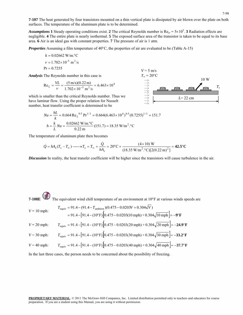
PROPRIETARY MATERIAL. © 2011 The McGraw-Hill Companies, Inc. Limited distribution permitted only to teachers and educators for course preparation. If you are a student using this Manual, you are using it without permission.
7-98
7-107 The heat generated by four transistors mounted on a thin vertical plate is dissipated by air blown over the plate on both surfaces. The temperature of the aluminum plate is to be determined.
Assumptions 1 Steady operating conditions exist. 2 The critical Reynolds number is Recr = 5×10⁵. 3 Radiation effects are negligible. 4 The entire plate is nearly isothermal. 5 The exposed surface area of the transistor is taken to be equal to its base area. 6 Air is an ideal gas with constant properties. 7 The pressure of air is 1 atm.
Properties Assuming a film temperature of 40°C, the properties of air are evaluated to be (Table A-15)
7255.0Pr
/sm 10702.1
C W/m.02662.025-
=×=
°=
ν
k
Analysis The Reynolds number in this case is 10 W
Ts
L= 22 cm
V = 5 m/s T∞ = 20°C
425 10463.6/sm 10702.1
m) m/s)(0.22 5(Re ×=×
==−ν
VLL
which is smaller than the critical Reynolds number. Thus we have laminar flow. Using the proper relation for Nusselt number, heat transfer coefficient is determined to be
C. W/m35.18)7.151(
m 22.0C W/m.02662.0
7.151)7255.0()10463.6(664.0PrRe664.0
2
3/15.043/15.0
°=°
==
=×===
NuLkh
khLNu L
The temperature of aluminum plate then becomes
C42.5°=°
×+°=+=⎯→⎯−= ∞∞ ])m 22.0(2)[C. W/m35.18(
W)104(C20)( 22s
sss hAQTTTThAQ&
&
Discussion In reality, the heat transfer coefficient will be higher since the transistors will cause turbulence in the air.
7-108E The equivalent wind chill temperature of an environment at 10°F at various winds speeds are
V = 10 mph: [ ][ ] F9°−=−°−−=
+−−−=
mph 100.304+mph) 10(0203.0475.0F)10(4.914.91
)304.00203.0475.0)(4.91(4.91 VVTT ambientequiv
V = 20 mph: [ ][ ] F24.9°−=−°−−= mph 200.304+mph) 20(0203.0475.0F)10(4.914.91equivT
V = 30 mph: [ ][ ] F33.2°−=−°−−= mph 300.304+mph) 30(0203.0475.0F)10(4.914.91equivT
V = 40 mph: [ ][ ] F37.7°−=−°−−= mph 400.304+mph) 40(0203.0475.0F)10(4.914.91equivT
In the last three cases, the person needs to be concerned about the possibility of freezing.
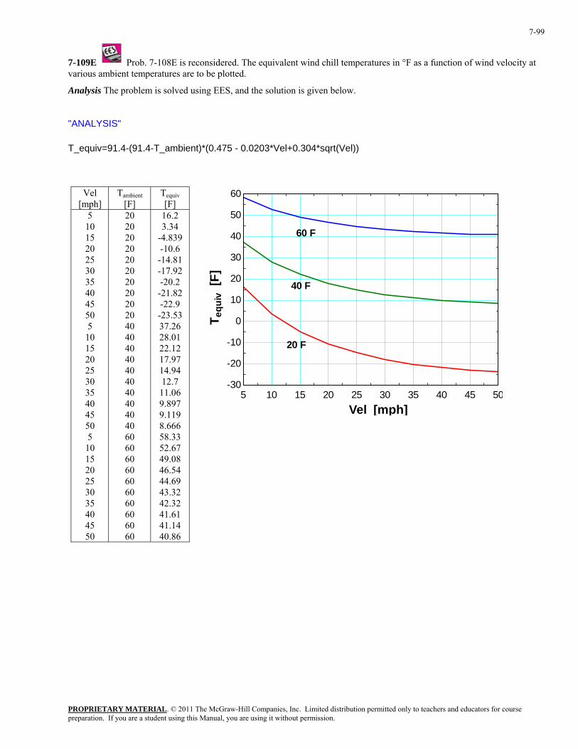
PROPRIETARY MATERIAL. © 2011 The McGraw-Hill Companies, Inc. Limited distribution permitted only to teachers and educators for course preparation. If you are a student using this Manual, you are using it without permission.
7-99
7-109E Prob. 7-108E is reconsidered. The equivalent wind chill temperatures in °F as a function of wind velocity at various ambient temperatures are to be plotted.
Analysis The problem is solved using EES, and the solution is given below.
"ANALYSIS" T_equiv=91.4-(91.4-T_ambient)*(0.475 - 0.0203*Vel+0.304*sqrt(Vel))
Vel [mph]
Tambient [F]
Tequiv [F]
5 10 15 20 25 30 35 40 45 50 5
10 15 20 25 30 35 40 45 50 5
10 15 20 25 30 35 40 45 50
20 20 20 20 20 20 20 20 20 20 40 40 40 40 40 40 40 40 40 40 60 60 60 60 60 60 60 60 60 60
16.2 3.34
-4.839 -10.6
-14.81 -17.92 -20.2
-21.82 -22.9
-23.53 37.26 28.01 22.12 17.97 14.94 12.7
11.06 9.897 9.119 8.666 58.33 52.67 49.08 46.54 44.69 43.32 42.32 41.61 41.14 40.86
5 10 15 20 25 30 35 40 45 50-30
-20
-10
0
10
20
30
40
50
60
Vel [mph]
T equ
iv [
F]
20 F
40 F
60 F
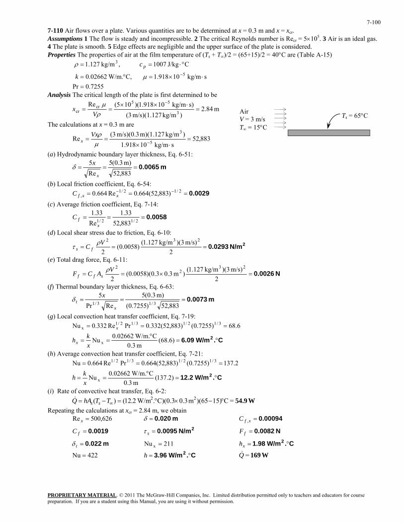
PROPRIETARY MATERIAL. © 2011 The McGraw-Hill Companies, Inc. Limited distribution permitted only to teachers and educators for course preparation. If you are a student using this Manual, you are using it without permission.
7-100
7-110 Air flows over a plate. Various quantities are to be determined at x = 0.3 m and x = xcr. Assumptions 1 The flow is steady and incompressible. 2 The critical Reynolds number is Recr = 5×10⁵. 3 Air is an ideal gas. 4 The plate is smooth. 5 Edge effects are negligible and the upper surface of the plate is considered. Properties The properties of air at the film temperature of (Ts + T∞)/2 = (65+15)/2 = 40°C are (Table A-15)
7255.0Pr
skg/m 10918.1 C, W/m.02662.0
CJ/kg 1007 ,kg/m 127.15
3
=⋅×=°=
°⋅==−µ
ρ
k
c p
Analysis The critical length of the plate is first determined to be
m 84.2)kg/m m/s)(1.127 3(
s)kg/m 10918.1)(105(Re3
55cr
cr =⋅××
==−
ρµ
Vx
Ts = 65°C Air V = 3 m/s T∞ = 15°C The calculations at x = 0.3 m are
883,52skg/m 10918.1
)kg/m m)(1.127 m/s)(0.3 3(Re
5
3=
⋅×==
−µρVx
x
(a) Hydrodynamic boundary layer thickness, Eq. 6-51:
m 0.0065===883,52m) 0.3(5
Re5
x
xδ
(b) Local friction coefficient, Eq. 6-54: 0.0029=== −− 2/12/1
, )883,52(664.0Re664.0 xxfC(c) Average friction coefficient, Eq. 7-14:
0.0058===2/12/1 883,52
33.1Re
33.1
xfC
(d) Local shear stress due to friction, Eq. 6-10:
2N/m 0.0293===2
m/s) )(3kg/m 127.1()0058.0(
2
232VC fsρτ
(e) Total drag force, Eq. 6-11:
N 0.0026=×==2
m/s) )(3kg/m 127.1()m 3.03.0)(0058.0(
2
232
2VACF sffρ
(f) Thermal boundary layer thickness, Eq. 6-63:
m 0.0073===883,52)7255.0(
m) 0.3(5RePr
53/13/1
xt
xδ
(g) Local convection heat transfer coefficient, Eq. 7-19: 6.68)7255.0()883,52(332.0PrRe332.0Nu 3/12/13/12/1
x === x
C. W/m6.09 2 °=°
== )6.68(m 3.0
C W/m.02662.0Nu xxkhx
(h) Average convection heat transfer coefficient, Eq. 7-21: 2.137)7255.0()883,52(664.0PrRe664.0Nu 3/12/13/12/1 ===
C. W/m12.2 2 °=°
== )2.137(m 3.0
C W/m.02662.0Nu xxkh
(i) Rate of convective heat transfer, Eq. 6-2: W54.9=C15))(65m 0.3C)(0.3. W/m2.12()( 22 °−×°=−= ∞TThAQ ss
& Repeating the calculations at xcr = 2.84 m, we obtain 626,500Re =x m 0.020=δ 0.00094=xfC ,
0.0019=fC 2N/m 0.0095=sτ N 0.0082=fF
m 0.022=tδ 211Nu x = C. W/m1.98 2 °=xh
422Nu = C. W/m3.96 2 °=h W169=Q&
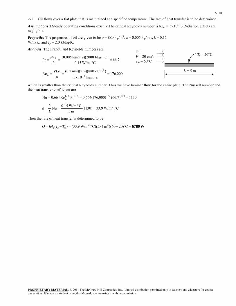
PROPRIETARY MATERIAL. © 2011 The McGraw-Hill Companies, Inc. Limited distribution permitted only to teachers and educators for course preparation. If you are a student using this Manual, you are using it without permission.
7-101
7-111 Oil flows over a flat plate that is maintained at a specified temperature. The rate of heat transfer is to be determined.
Assumptions 1 Steady operating conditions exist. 2 The critical Reynolds number is Recr = 5×10⁵. 3 Radiation effects are negligible.
Properties The properties of oil are given to be ρ = 880 kg/m3, µ = 0.005 kg/m.s, k = 0.15 W/m⋅K, and cp = 2.0 kJ/kg⋅K.
Analysis The Prandtl and Reynolds numbers are Oil V = 20 cT
m/s0°C ∞ = 6
Ts = 20°C
L = 5 m
7.66C W/m15.0
C)J/kg s)(2000kg/m 005.0(Pr =°⋅
°⋅⋅==
kc pµ
000,176skg/m 105
)kg/m m)(880 m/s)(5 2.0(Re3
3=
⋅×==
−µρVL
L
which is smaller than the critical Reynolds number. Thus we have laminar flow for the entire plate. The Nusselt number and the heat transfer coefficient are
1130)7.66()000,176(664.0PrRe664.0Nu 3/12/13/12/1 === L
C. W/m9.33)1130(m 5
C W/m.15.0Nu 2 °=°
==Lkh
Then the rate of heat transfer is determined to be
W6780=C)20)(60m 1C)(5. W/m9.33()( 22 °−×°=−= ∞TThAQ ss&
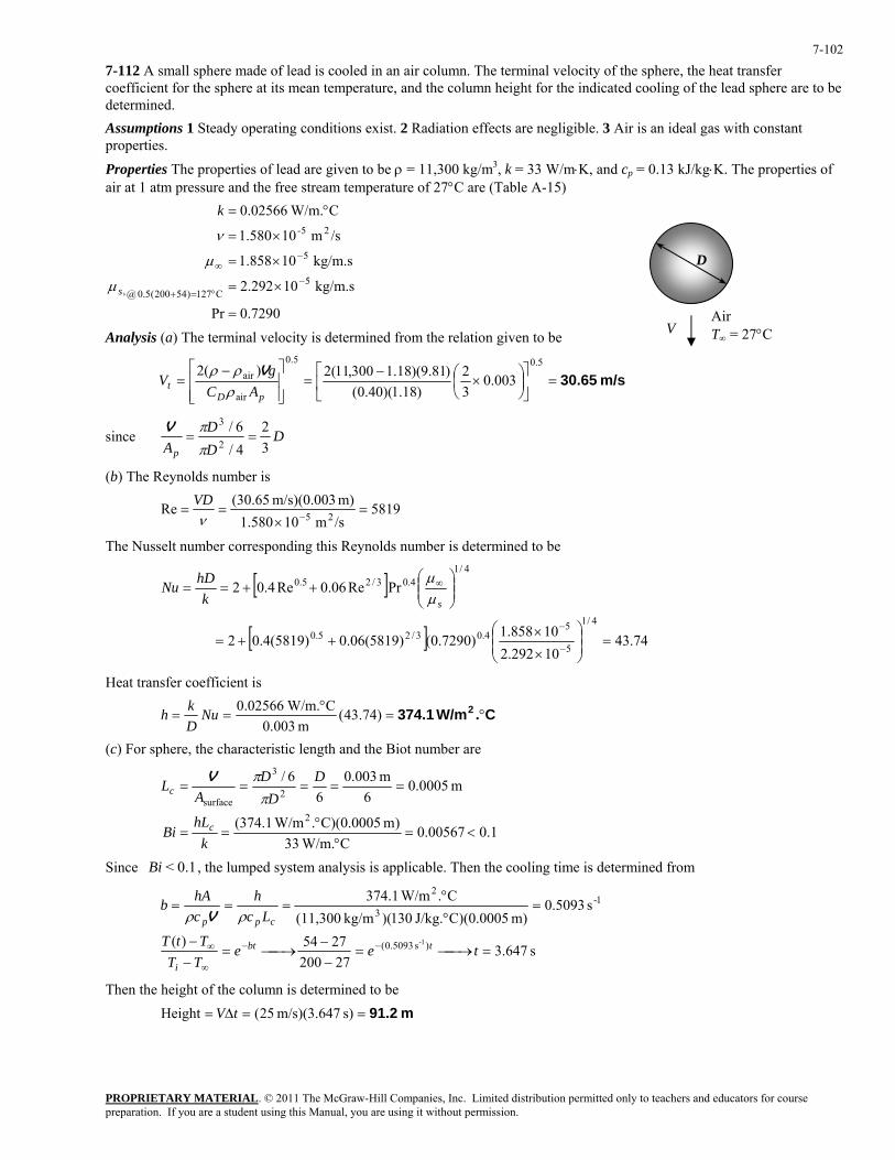
PROPRIETARY MATERIAL. © 2011 The McGraw-Hill Companies, Inc. Limited distribution permitted only to teachers and educators for course preparation. If you are a student using this Manual, you are using it without permission.
7-102
7-112 A small sphere made of lead is cooled in an air column. The terminal velocity of the sphere, the heat transfer coefficient for the sphere at its mean temperature, and the column height for the indicated cooling of the lead sphere are to be determined. Assumptions 1 Steady operating conditions exist. 2 Radiation effects are negligible. 3 Air is an ideal gas with constant properties. Properties The properties of lead are given to be ρ = 11,300 kg/m3, k = 33 W/m⋅K, and cp = 0.13 kJ/kg⋅K. The properties of air at 1 atm pressure and the free stream temperature of 27°C are (Table A-15)
7290.0Pr
kg/m.s 10292.2
kg/m.s 10858.1
/sm 10580.1
C W/m.02566.0
5C127)54200(5.0@,
5
25-
=
×=
×=
×=
°=
−°=+
−∞
s
k
µ
µ
ν
D
Air T∞ = 27°C V Analysis (a) The terminal velocity is determined from the relation given to be
m/s 30.65=⎥⎦
⎤⎢⎣
⎡⎟⎠⎞
⎜⎝⎛ ×
−=
⎥⎥⎦
⎤
⎢⎢⎣
⎡ −=
5.05.0
air
air 003.032
)18.1)(40.0()81.9)(18.1300,11(2)(2
pDt AC
gV
ρρρ V
since DDD
Ap 32
4/6/
2
3==
ππV
(b) The Reynolds number is
5819/sm 10580.1m) m/s)(0.003 (30.65Re 25 =
×==
−νVD
The Nusselt number corresponding this Reynolds number is determined to be
[ ]
[ ] 74.4310292.210858.1)7290.0()5819(06.0)5819(4.02
PrRe06.0Re4.02
4/1
5
54.03/25.0
4/14.03/25.0
=⎟⎟⎠
⎞⎜⎜⎝
⎛
×
×++=
⎟⎟⎠
⎞⎜⎜⎝
⎛++==
−
−
∞
skhDNu
µµ
Heat transfer coefficient is
C. W/m374.1 2 °=°
== )74.43(m 003.0
C W/m.02566.0NuDkh
(c) For sphere, the characteristic length and the Biot number are
1.0 00567.0C W/m.33
)m 0005.0)(C. W/m1.374(
m 0005.06
m 003.06
6/
2
2
3
surface
<=°
°==
=====
khL
Bi
DD
DA
L
c
c ππV
Since , the lumped system analysis is applicable. Then the cooling time is determined from 0.1< Bi
s 647.3
272002754)(
s 5093.0m) C)(0.0005J/kg. 130)(kg/m (11,300
C. W/m1.374
)s 5093.0(
1-3
2
1-=⎯→⎯=
−−
⎯→⎯=−−
=°
°===
−−
∞
∞ teeTTTtT
Lch
chAb
tbt
i
cpp ρρ V
Then the height of the column is determined to be m 91.2==∆= s) m/s)(3.647 25(Height tV
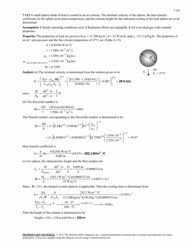
PROPRIETARY MATERIAL. © 2011 The McGraw-Hill Companies, Inc. Limited distribution permitted only to teachers and educators for course preparation. If you are a student using this Manual, you are using it without permission.
7-103
7-113 A small sphere made of lead is cooled in an air column. The terminal velocity of the sphere, the heat transfer coefficient for the sphere at its mean temperature, and the column height for the indicated cooling of the lead sphere are to be determined. Assumptions 1 Steady operating conditions exist. 2 Radiation effects are negligible. 3 Air is an ideal gas with constant properties. Properties The properties of lead are given to be ρ = 11,300 kg/m3, k = 33 W/m⋅K, and cp = 0.13 kJ/kg⋅K. The properties of air at 1 atm pressure and the free stream temperature of 27°C are (Table A-15)
7290.0Pr
kg/m.s 10292.2
kg/m.s 10858.1
/sm 10580.1
C W/m.02566.0
5C127)54200(5.0@,
5
25-
=
×=
×=
×=
°=
−°=+
−∞
s
k
µ
µ
ν
D
Air T∞ = 27°C V Analysis (a) The terminal velocity is determined from the relation given to be
m/s 28.0=⎥⎦
⎤⎢⎣
⎡⎟⎠⎞
⎜⎝⎛ ×
−=
⎥⎥⎦
⎤
⎢⎢⎣
⎡ −=
5.05.0
air
air 005.032
)18.1)(40.0()81.9)(18.1300,11(2)(2
pDt AC
gV
ρρρ V
since DDD
Ap 32
4/6/
2
3==
ππV
(b) The Reynolds number is
8861/sm 10580.1m) m/s)(0.005 (28.0
Re25
=×
==−ν
VD
The Nusselt number corresponding to this Reynolds number is determined to be
[ ]
[ ] 97.5410292.210858.1)7290.0()8861(06.0)8861(4.02
PrRe06.0Re4.02
4/1
5
54.03/25.0
4/14.03/25.0
=⎟⎟⎠
⎞⎜⎜⎝
⎛
×
×++=
⎟⎟⎠
⎞⎜⎜⎝
⎛++==
−
−
∞
skhDNu
µµ
Heat transfer coefficient is
C. W/m282.1 2 °=°
== )97.54(m 005.0
C W/m.02566.0NuDkh
(c) For sphere, the characteristic length and the Biot number are
1.0 0071.0C W/m.33
)m 0008333.0)(C. W/m1.282(
m 0008333.06
m 005.06
6/
2
2
3
surface
<=°
°==
=====
khL
Bi
DD
DA
L
c
cπ
πV
Since , the lumped system analysis is applicable. Then the cooling time is determined from 0.1< Bi
s 06.8
272002754)(
s 2305.0m) 33C)(0.00083J/kg. 130)(kg/m (11,300
C. W/m1.282
)s 2305.0(
1-3
2
1-=⎯→⎯=
−−
⎯→⎯=−−
=°
°===
−−
∞
∞ teeTTTtT
Lch
chAb
tbt
i
cpp ρρ V
Then the height of the column is determined to be m 226==∆= s) m/s)(8.06 28(Height tV
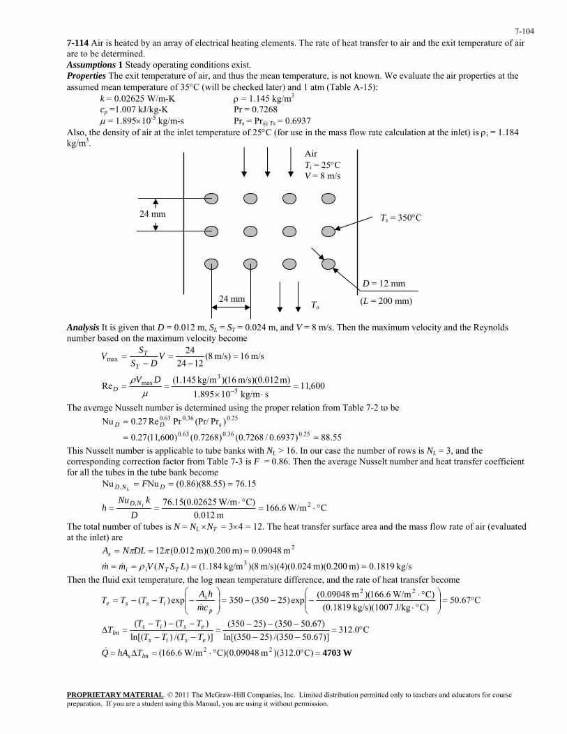
PROPRIETARY MATERIAL. © 2011 The McGraw-Hill Companies, Inc. Limited distribution permitted only to teachers and educators for course preparation. If you are a student using this Manual, you are using it without permission.
7-104
7-114 Air is heated by an array of electrical heating elements. The rate of heat transfer to air and the exit temperature of air are to be determined. Assumptions 1 Steady operating conditions exist. Properties The exit temperature of air, and thus the mean temperature, is not known. We evaluate the air properties at the assumed mean temperature of 35°C (will be checked later) and 1 atm (Table A-15):
k = 0.02625 W/m-K ρ = 1.145 kg/m3
cp =1.007 kJ/kg-K Pr = 0.7268 µ = 1.895×10⁻⁵ kg/m-s Prs = Pr@ Ts = 0.6937
Also, the density of air at the inlet temperature of 25°C (for use in the mass flow rate calculation at the inlet) is ρi = 1.184 kg/m3.
24 mm
24 mm
D = 12 mm
(L = 200 mm)
Air Ti = 25°C V = 8 m/s
Ts = 350°C
To Analysis It is given that D = 0.012 m, SL = ST = 0.024 m, and V = 8 m/s. Then the maximum velocity and the Reynolds number based on the maximum velocity become
m/s 16m/s) 8(1224
24max =
−=
−= V
DSS
VT
T
600,11skg/m 10895.1
m) m/s)(0.012 16)(kg/m 145.1(Re 5
3max =
⋅×==
−µρ DV
D
The average Nusselt number is determined using the proper relation from Table 7-2 to be
55.88)6937.0/7268.0()7268.0()600,11(27.0
)Pr(Pr/PrRe27.0Nu25.036.063.0
25.036.063.0
==
= sDD
This Nusselt number is applicable to tube banks with NL > 16. In our case the number of rows is NL = 3, and the corresponding correction factor from Table 7-3 is F = 0.86. Then the average Nusselt number and heat transfer coefficient for all the tubes in the tube bank become
15.76)55.88)(86.0(NuNu , === DND FL
C W/m6.166m 0.012
C) W/m02625.0(15.76 2, °⋅=°⋅
==D
kNuh LND
The total number of tubes is N = NL ×NT = 3×4 = 12. The heat transfer surface area and the mass flow rate of air (evaluated at the inlet) are
2m 09048.0 m) m)(0.200 012.0(12 === ππDLNAs
kg/s 1819.0m) m)(0.200 024m/s)(4)(0. 8)(kg/m 184.1()( 3 ==== LSNVmm TTii ρ&& Then the fluid exit temperature, the log mean temperature difference, and the rate of heat transfer become
C67.50C)J/kg kg/s)(1007 (0.1819
C) W/m6.166)(m 09048.0(exp)25350(350exp)(22
°=⎟⎟⎠
⎞⎜⎜⎝
⎛
°⋅°⋅
−−−=⎟⎟⎠
⎞⎜⎜⎝
⎛−−−=
p
sisse cm
hATTTT
&
C0.312)]67.50350/()25350ln[()67.50350()25350(
)]/()ln[()()(
°=−−−−−
=−−−−−
=∆esis
esislm TTTT
TTTTT
W4703=°°⋅=∆= )C0.312)(m C)(0.09048 W/m6.166( 22lms ThAQ&

PROPRIETARY MATERIAL. © 2011 The McGraw-Hill Companies, Inc. Limited distribution permitted only to teachers and educators for course preparation. If you are a student using this Manual, you are using it without permission.
7-105
7-115E A 15-ft long strip of sheet metal is being transported on a conveyor, while the coating on the upper surface is being cured by infrared lamps. The surface temperature of the sheet metal is to be determined.
Assumptions 1 Steady operating conditions exist. 2 Heat conduction through the sheet metal is negligible. 3 Thermal properties are constant. 4 The surrounding ambient air is at 1 atm. 5 The critical Reynolds number is Recr = 5×10⁵.
Properties The properties of air at 180°F are k = 0.01715 Btu/h·ft·R, ν = 2.281 × 10⁻⁴ ft2/s, Pr = 0.7148 (from Table A-15E).
Analysis The Reynolds number for L = 15 ft is
624 10052.1/sft 10281.2
)ft 15)(ft/s 16(Re ×=×
==−ν
VLL
Since 5 × 10⁵ < ReL < 107, the flow is a combined laminar and turbulent flow. Using the proper relation for Nusselt number, the average heat transfer coefficient on the sheet metal is
1395)7148.0](871)10052.1(037.0[Pr)871Re037.0(Nu 3/18.063/18.0 =−×=−== LkhL
RftBtu/h 595.1ft 15
RftBtu/h 01715.013951395 2 ⋅⋅=⋅⋅
==Lkh
From energy balance, we have
→ 0convradabsorbed =−− QQQ &&& 02 convradabsorbed =−− qAqAqA &&&
or 0)(2)( 4surr
4incident =−−−− ∞TThTTq ssεσα &
Copy the following lines and paste on a blank EES screen to solve the above equation: h=1.595 T_inf=77+460 T_surr=77+460 q_incindent=1500 alpha=0.6 epsilon=0.7 sigma=0.1714e-8 alpha*q_incindent-epsilon*sigma*(T_s^4-T_surr^4)-2*h*(T_s-T_inf)=0
Solving by EES software, the surface temperature of the sheet metal is
F279°== R 739sT
Discussion Since the value of the (force) convection heat transfer coefficient is relatively small, this indicates that natural convection may play an important role.
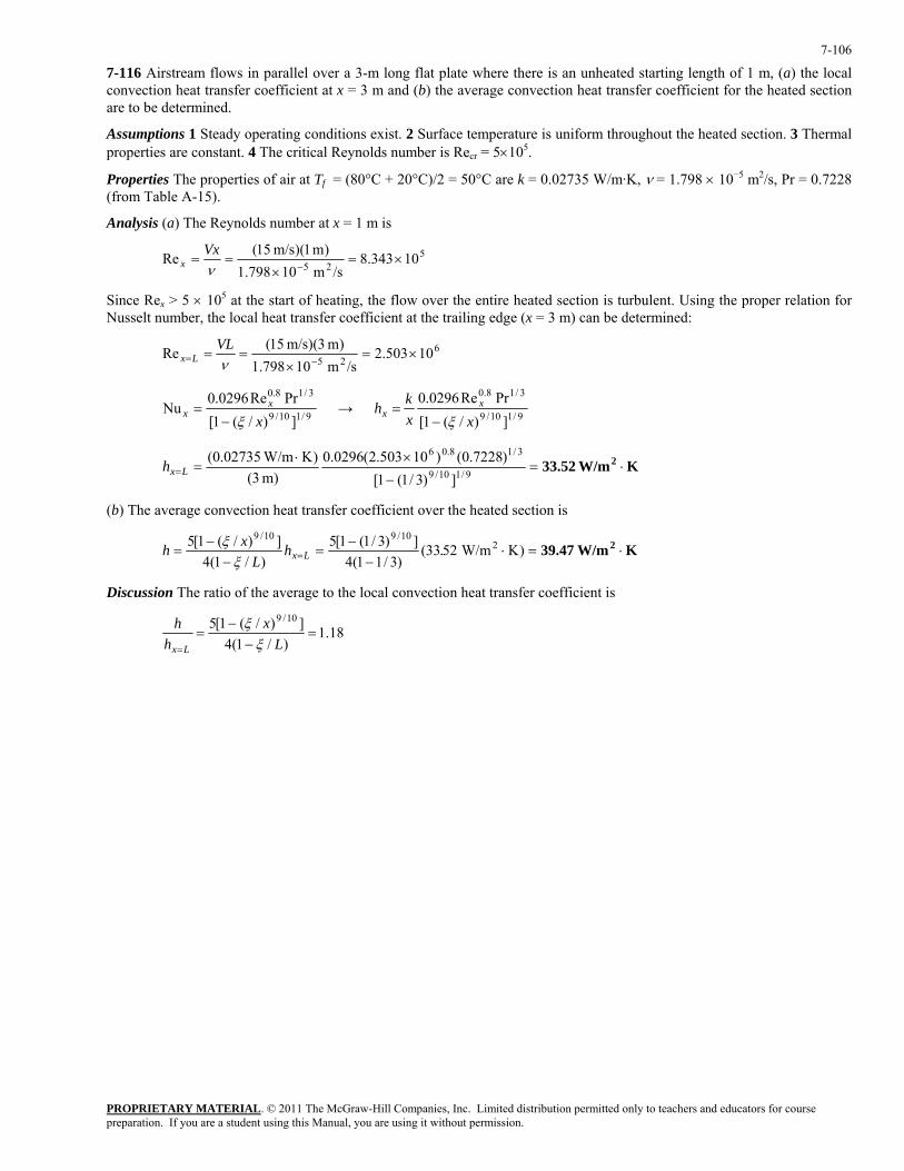
PROPRIETARY MATERIAL. © 2011 The McGraw-Hill Companies, Inc. Limited distribution permitted only to teachers and educators for course preparation. If you are a student using this Manual, you are using it without permission.
7-106
7-116 Airstream flows in parallel over a 3-m long flat plate where there is an unheated starting length of 1 m, (a) the local convection heat transfer coefficient at x = 3 m and (b) the average convection heat transfer coefficient for the heated section are to be determined.
Assumptions 1 Steady operating conditions exist. 2 Surface temperature is uniform throughout the heated section. 3 Thermal properties are constant. 4 The critical Reynolds number is Recr = 5×10⁵.
Properties The properties of air at Tf = (80°C + 20°C)/2 = 50°C are k = 0.02735 W/m·K, ν = 1.798 × 10⁻⁵ m2/s, Pr = 0.7228 (from Table A-15).
Analysis (a) The Reynolds number at x = 1 m is
525 10343.8/sm 10798.1
)m 1)(m/s 15(Re ×=×
==−ν
Vxx
Since Rex > 5 × 10⁵ at the start of heating, the flow over the entire heated section is turbulent. Using the proper relation for Nusselt number, the local heat transfer coefficient at the trailing edge (x = 3 m) can be determined:
625 10503.2/sm 10798.1
)m 3)(m/s 15(Re ×=×
==−= ν
VLLx
9/110/9
3/18.0
])/(1[PrRe0296.0
Nux
xx
ξ−= → 9/110/9
3/18.0
])/(1[PrRe0296.0
xxkh x
xξ−
=
K W/m33.52 2 ⋅=−
×⋅== 9/110/9
3/18.06
])3/1(1[)7228.0()10503.2(0296.0
m) 3()K W/m02735.0(
Lxh
(b) The average convection heat transfer coefficient over the heated section is
K W/m39.47 2 ⋅=⋅−
−=
−−
= = )KW/m5233()3/11(4
])3/1(1[5)/1(4
])/(1[5 210/910/9
.hL
xh Lxξξ
Discussion The ratio of the average to the local convection heat transfer coefficient is
18.1)/1(4
])/(1[5 10/9=
−−
== L
xh
h
Lx ξξ
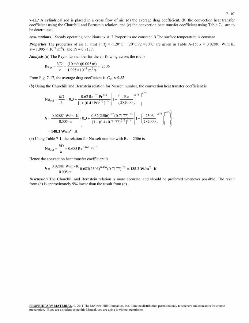
PROPRIETARY MATERIAL. © 2011 The McGraw-Hill Companies, Inc. Limited distribution permitted only to teachers and educators for course preparation. If you are a student using this Manual, you are using it without permission.
7-107
7-117 A cylindrical rod is placed in a cross flow of air, (a) the average drag coefficient, (b) the convection heat transfer coefficient using the Churchill and Bernstein relation, and (c) the convection heat transfer coefficient using Table 7-1 are to be determined.
Assumptions 1 Steady operating conditions exist. 2 Properties are constant. 3 The surface temperature is constant.
Properties The properties of air (1 atm) at Tf = (120°C + 20°C)/2 =70°C are given in Table A-15: k = 0.02881 W/m·K, ν = 1.995 × 10⁻⁵ m2/s, and Pr = 0.7177.
Analysis (a) The Reynolds number for the air flowing across the rod is
2506/sm 10995.1)m 005.0)(m/s 10(Re 25 =
×==
−νVD
D
From Fig. 7-17, the average drag coefficient is 0.85≈DC .
(b) Using the Churchill and Bernstein relation for Nusselt number, the convection heat transfer coefficient is
5/48/5
4/13/2
3/12/1
cyl 282000Re1
]Pr)/4.0(1[PrRe62.03.0Nu
⎥⎥⎦
⎤
⎢⎢⎣
⎡⎟⎠⎞
⎜⎝⎛+
++==
khD
K W/m148.3 2 ⋅=
⎪⎭
⎪⎬⎫
⎪⎩
⎪⎨⎧
⎥⎥⎦
⎤
⎢⎢⎣
⎡⎟⎠⎞
⎜⎝⎛+
++
⋅=
5/48/5
4/13/2
3/12/1
28200025061
])7177.0/4.0(1[)7177.0()2506(62.03.0
m 0050K W/m02881.0
.h
(c) Using Table 7-1, the relation for Nusselt number with Re = 2506 is
3/1466.0cyl PrRe683.0Nu ==
khD
Hence the convection heat transfer coefficient is
K W/m135.2 2 ⋅=⋅
= 3/1466.0 )7177.0()2506(683.0m 0050
K W/m02881.0.
h
Discussion The Churchill and Bernstein relation is more accurate, and should be preferred whenever possible. The result from (c) is approximately 9% lower than the result from (b).
PROPRIETARY MATERIAL. © 2011 The McGraw-Hill Companies, Inc. Limited distribution permitted only to teachers and educators for course preparation. If you are a student using this Manual, you are using it without permission.
7-108
Fundamentals of Engineering (FE) Exam Problems
7-118 Air at 20ºC flows over a 4-m long and 3-m wide surface of a plate whose temperature is 80ºC with a velocity of 5 m/s. The rate of heat transfer from the surface is
(a) 7383 W (b) 8985 W (c) 11,231 W (d) 14,672 W (e) 20,402 W
(For air, use k=0.02735 W/m⋅°C, Pr = 0.7228, ν =1.798×10⁻⁵ m2/s.)
Answer (a) 7383 W
Solution Solved by EES Software. Solutions can be verified by copying-and-pasting the following lines on a blank EES screen.
T_infinity=20 [C] T_s=80 [C] L=4 [m] W=3 [m] V=5 [m/s] "Properties of air at the film temperature of (80+20)/2=50C are (Table A-15)" k=0.02735 [W/m-C] nu=1.798E-5 [m^2/s] Pr=0.7228 Re=(V*L)/nu "The calculated Re number is greater than critical number, and therefore we have combined laminar-turbulent flow" Nus=(0.037*Re^0.8-871)*Pr^(1/3) h=k/L*Nus A_s=L*W Q_dot=h*A_s*(T_s-T_infinity) "Some Wrong Solutions with Common Mistakes" W1_Nus=0.037*Re^0.8*Pr^(1/3) "Using turbulent flow relation" W1_h=k/L*W1_Nus W1_Q_dot=W1_h*A_s*(T_s-T_infinity)
PROPRIETARY MATERIAL. © 2011 The McGraw-Hill Companies, Inc. Limited distribution permitted only to teachers and educators for course preparation. If you are a student using this Manual, you are using it without permission.
7-109
7-119 Air at 20ºC flows over a 4-m long and 3-m wide surface of a plate whose temperature is 80ºC with a velocity of 7 m/s. The length of the surface for which the flow remains laminar is
(a) 0.9 m (b) 1.3 m (c) 1.8 m (d) 2.2 m (e) 3.7 m
(For air, use k = 0.02735 W/m⋅°C, Pr = 0.7228, ν =1.798×10⁻⁵ m2/s.)
Answer (b) 1.3 m
Solution Solved by EES Software. Solutions can be verified by copying-and-pasting the following lines on a blank EES screen.
T_infinity=20 [C] T_s=80 [C] L=4 [m] W=3 [m] V=7 [m/s] "Properties of air at the film temperature of (80+20)/2=50C are (Table A-15)" k=0.02735 [W/m-C] nu=1.798E-5 [m^2/s] Pr=0.7228 Re_cr=5E5 x_cr=(Re_cr*nu)/V
PROPRIETARY MATERIAL. © 2011 The McGraw-Hill Companies, Inc. Limited distribution permitted only to teachers and educators for course preparation. If you are a student using this Manual, you are using it without permission.
7-110
7-120 Air at 20ºC flows over a 4-m long and 3-m wide surface of a plate whose temperature is 80ºC with a velocity of 5 m/s. The rate of heat transfer from the laminar flow region of the surface is
(a) 950 W (b) 1037 W (c) 2074 W (d) 2640 W (e) 3075 W
(For air, use k=0.02735 W/m⋅°C, Pr = 0.7228, ν =1.798×10⁻⁵ m2/s.)
Answer (c) 2074 W
Solution Solved by EES Software. Solutions can be verified by copying-and-pasting the following lines on a blank EES screen.
T_infinity=20 [C] T_s=80 [C] L=4 [m] W=3 [m] V=5 [m/s] "Properties of air at the film temperature of (80+20)/2=50C are (Table A-15)" k=0.02735 [W/m-C] nu=1.798E-5 [m^2/s] Pr=0.7228 Re_cr=5E5 x_cr=(Re_cr*nu)/V Nus=0.664*Re_cr^0.5*Pr^(1/3) h=k/x_cr*Nus A_laminar=x_cr*W Q_dot=h*A_laminar*(T_s-T_infinity) "Some Wrong Solutions with Common Mistakes" W_Nus=0.332*Re_cr^0.5*Pr^(1/3) "Using local Nusselt number relation" W_h=k/x_cr*W_Nus W_Q_dot=W_h*A_laminar*(T_s-T_infinity)
7-121 For laminar flow of a fluid along a flat plate, one would expect the largest local convection heat transfer coefficient for the same Reynolds and Prandtl numbers when
(a) The same temperature is maintained on the surface
(b) The same heat flux is maintained on the surface
(c) The plate has an unheated section
(d) The plate surface is polished
(e) None of the above
Answer (b)
PROPRIETARY MATERIAL. © 2011 The McGraw-Hill Companies, Inc. Limited distribution permitted only to teachers and educators for course preparation. If you are a student using this Manual, you are using it without permission.
7-111
7-122 Air at 15ºC flows over a flat plate subjected to a uniform heat flux of 240 W/m2 with a velocity of 3.5 m/s. The surface temperature of the plate 6 m from the leading edge is
(a) 40.5ºC (b) 41.5ºC (c) 58.2 ºC (d) 95.4ºC (e) 134ºC
(For air, use k=0.02551 W/m⋅°C, Pr = 0.7296, ν =1.562×10⁻⁵ m2/s.)
Answer (a) 40.5ºC
Solution Solved by EES Software. Solutions can be verified by copying-and-pasting the following lines on a blank EES screen.
T_infinity=15 [C] q_dot=240 [W/m^2] V=3.5 [m/s] x=6 [m] "Properties of air at 25 C are (Table A-15)" k=0.02551 [W/m-C] nu=1.562E-5 [m^2/s] Pr=0.7296 Re_x=(V*x)/nu "The calculated Re number is greater than critical number, and therefore we have turbulent flow at the specified location" Nus=0.0308*Re_x^0.8*Pr^(1/3) h=k/x*Nus q_dot=h*(T_s-T_infinity) "Some Wrong Solutions with Common Mistakes" W1_Nus=0.453*Re_x^0.5*Pr^(1/3) "Using laminar flow Nusselt number relation for q_dot = constant" W1_h=k/x*W1_Nus q_dot=W1_h*(W1_T_s-T_infinity) W2_Nus=0.0296*Re_x^0.8*Pr^(1/3) "Using turbulent flow Nusselt number relation for T_s = constant" W2_h=k/x*W2_Nus q_dot=W2_h*(W2_T_s-T_infinity)
PROPRIETARY MATERIAL. © 2011 The McGraw-Hill Companies, Inc. Limited distribution permitted only to teachers and educators for course preparation. If you are a student using this Manual, you are using it without permission.
7-112
7-123 Water at 75ºC flows over a 2-m-long, 2-m-wide surface of a plate whose temperature is 5ºC with a velocity of 1.5 m/s. The total drag force acting on the plate is
(a) 2.8 N (b) 12.3 N (c) 13.7 N (d) 15.4 N (e) 20.0 N
(For air, use ν =0.658×10⁻⁶ m2/s, ρ = 992 kg/m3.)
Answer (c) 13.7 N
Solution Solved by EES Software. Solutions can be verified by copying-and-pasting the following lines on a blank EES screen.
T_infinity=75 [C] T_s=5 [C] L=2 [m] W=2 [m] V=1.5 [m/s] "Properties of water at the film temperature of (75+5)/2=40C are (Table A-9)" nu=0.658E-6 [m^2/s] rho=992 [kg/m^3] Re=(V*L)/nu "The calculated Re number is greater than critical number, and therefore we have combined laminar-turbulent flow" C_f=0.074/Re^(1/5)-1742/Re A_s=L*W F_D=C_f*A_s*(rho*V^2)/2 "Some Wrong Solutions with Common Mistakes" W1_C_f=0.074/Re^(1/5) "Using turbulent flow relation" W1_F_D=W1_C_f*A_s*(rho*V^2)/2 W2_C_f=1.328/Re^(1/2) "Using laminar flow relation" W2_F_D=W2_C_f*A_s*(rho*V^2)/2 W3_C_f=0.0592/Re^(1/5) "Using local turbulent flow relation" W3_F_D=W3_C_f*A_s*(rho*V^2)/2
PROPRIETARY MATERIAL. © 2011 The McGraw-Hill Companies, Inc. Limited distribution permitted only to teachers and educators for course preparation. If you are a student using this Manual, you are using it without permission.
7-113
7-124 Engine oil at 105ºC flows over the surface of a flat plate whose temperature is 15ºC with a velocity of 1.5 m/s. The local drag force per unit surface area 0.8 m from the leading edge of the plate is
(a) 21.8 N/m2 (b) 14.3 N/m2 (c) 10.9 N/m2 (d) 8.5 N/m2 (e) 5.5 N/m2
(For oil, use ν =8.565×10⁻⁵ m2/s, ρ = 864 kg/m3.)
Answer (e) 5.5 N/m2
Solution Solved by EES Software. Solutions can be verified by copying-and-pasting the following lines on a blank EES screen.
T_infinity=105 [C] T_s=15 [C] V=1.5 [m/s] x=0.8 [m] "Properties of oil at the film temperature of (105+15)/2=60C are (Table A-13)" rho=864 [kg/m^3] nu=8.565E-5 [m^2/s] Re_x=(V*x)/nu "The calculated Re number is smaller than the critical number, and therefore we have laminar flow" C_f_x=0.664/Re_x^(1/2) F_D=C_f_x*(rho*V^2)/2 "Some Wrong Solutions with Common Mistakes" W1_C_f_x=0.0592/Re_x^(1/5) "Using local turbulent flow relation" W1_F_D=W1_C_f_x*(rho*V^2)/2 W2_C_f_x=1.328/Re_x^(1/2) "Using average laminar flow relation" W2_F_D=W2_C_f_x*(rho*V^2)/2
PROPRIETARY MATERIAL. © 2011 The McGraw-Hill Companies, Inc. Limited distribution permitted only to teachers and educators for course preparation. If you are a student using this Manual, you are using it without permission.
7-114
7-125 Air at 25ºC flows over a 4-cm-diameter, 1.7-m-long pipe with a velocity of 4 m/s. A refrigerant at −15ºC flows inside the pipe and the surface temperature of the pipe is essentially the same as the refrigerant temperature inside. Air properties at the average temperature are k=0.0240 W/m⋅°C, Pr = 0.735, ν = 1.382×10⁻⁵ m2/s. The rate of heat transfer to the pipe is
(a) 126 W (b) 245 W (c) 302 W (d) 415 W (e) 556 W
Answer (c) 302 W
Solution Solved by EES Software. Solutions can be verified by copying-and-pasting the following lines on a blank EES screen.
T_infinity=25 [C] T_s=-15 [C] D=0.04 [m] L=1.7 [m] V=4 [m/s] "Properties of air at the film temperature of (25-15)/2=5 C are (Table A-15)" k=0.0240 [W/m-C] nu=1.382E-5 [m^2/s] Pr=0.735 Re=(V*D)/nu Nus=0.3+(0.62*Re^(1/2)*Pr^(1/3))/(1+(0.4/Pr)^(2/3))^(1/4)*(1+(Re/282000)^(5/8))^(4/5) h=k/D*Nus A_s=pi*D*L Q_dot=h*A_s*(T_infinity-T_s)
7-126 Air at 25ºC flows over a 5-cm-diameter, 1.7-m-long smooth pipe with a velocity of 4 m/s. A refrigerant at -15ºC flows inside the pipe and the surface temperature of the pipe is essentially the same as the refrigerant temperature inside. The drag force exerted on the pipe by the air is
(a) 0.4 N (b) 1.1 N (c) 8.5 N (d) 13 N (e) 18 N
(For air, use ν =1.382×10⁻⁵ m2/s, ρ = 1.269 kg/m3.)
Answer (b) 1.1 N
Solution Solved by EES Software. Solutions can be verified by copying-and-pasting the following lines on a blank EES screen.
T_infinity=25 [C] T_s=-15 [C] D=0.05 [m] L=1.7 [m] V=4 [m/s] "Properties of air at the film temperature of (25-15)/2=5 C are (Table A-15)" rho=1.269 [kg/m^3] nu=1.382E-5 [m^2/s] Re=(V*D)/nu "The drag coefficient corresponding to the calculated Re = 14,472 is (Fig. 7-17)" C_D=1.3 A=L*D F_D=C_D*A*rho*V^2/2

PROPRIETARY MATERIAL. © 2011 The McGraw-Hill Companies, Inc. Limited distribution permitted only to teachers and educators for course preparation. If you are a student using this Manual, you are using it without permission.
7-115
7-127 Kitchen water at 10ºC flows over a 10-cm-diameter pipe with a velocity of 1.1 m/s. Geothermal water enters the pipe at 90ºC at a rate of 1.25 kg/s. For calculation purposes, the surface temperature of the pipe may be assumed to be 70ºC. If the geothermal water is to leave the pipe at 50ºC, the required length of the pipe is
(a) 1.1 m (b) 1.8 m (c) 2.9 m (d) 4.3 m (e) 7.6 m
(For both water streams, use k = 0.631 W/m⋅°C, Pr = 4.32, ν =0.658×10⁻⁶ m2/s, cp = 4179 J/kg⋅°C.)
Answer (c) 2.9 m
Solution Solved by EES Software. Solutions can be verified by copying-and-pasting the following lines on a blank EES screen.
T_infinity=10 [C] D=0.10 [m] V=1.1 [m/s] T_s=70 [C] T_geo_in=90 [C] T_geo_out=50 [C] m_dot_geo=1.25 [kg/s] "Properties of water at the film temperature of (10+70)/2=40 C are (Table A-9)" k=0.631 [W/m-C] Pr=4.32 c_p=4179 [J/kg-C] nu=0.658E-6 [m^2/s] Re=(V*D)/nu Nus=0.3+(0.62*Re^(1/2)*Pr^(1/3))/(1+(0.4/Pr)^(2/3))^(1/4)*(1+(Re/282000)^(5/8))^(4/5) h=k/D*Nus q=h*(T_s-T_infinity) Q_dot=m_dot_geo*c_p*( T_geo_in-T_geo_out) A_s=Q_dot/q L=A_s/(pi*D)
PROPRIETARY MATERIAL. © 2011 The McGraw-Hill Companies, Inc. Limited distribution permitted only to teachers and educators for course preparation. If you are a student using this Manual, you are using it without permission.
7-116
7-128 Jakob suggests the following correlation be used for square tubes in a liquid cross-flow situation: . Water (k = 0.61 W/m⋅K, Pr = 6) at 503/10.675 Pr0.102ReNu = oC flows across a 1 cm square tube with a Reynolds number
of 10,000 and surface temperature of 75oC. If the tube is 3 m long, the rate of heat transfer between the tube and water is
(a) 9.8 kW (b) 12.4 kW (c) 17.0 kW (d) 19.6 kW (e) 24.0 kW
Answer (c) 17.0 kW
Solution Solved by EES Software. Solutions can be verified by copying-and-pasting the following lines on a blank EES screen.
k=0.61 [W/m-K] Pr = 6 L=0.01 [m] Lg=3 [m] DT=25 [K] Re=10000 Nus=0.102*Re^0.675*Pr^0.333 h=Nus*k/L Q=4*L*Lg*h*DT
7-129 Wind at 30ºC flows over a 0.5-m-diameter spherical tank containing iced water at 0ºC with a velocity of 25 km/h. If the tank is thin-shelled with a high thermal conductivity material, the rate at which ice melts is
(a) 4.78 kg/h (b) 6.15 kg/h (c) 7.45 kg/h (d) 11.8 kg/h (e) 16.0 kg/h
(Take hif = 333.7 kJ/kg and use the following for air: k=0.02588 W/m⋅°C, Pr = 0.7282, ν =1.608×10⁻⁵ m2/s, µ∞ =1.872×10⁻⁵ kg/m⋅s, µs = 1.729×10⁻⁵ kg/m⋅s)
Answer (a) 4.78 kg/h
Solution Solved by EES Software. Solutions can be verified by copying-and-pasting the following lines on a blank EES screen.
D=0.5 [m] T_infinity=30 [C] T_s=0 [C] V=25 [km/h]*Convert(km/h, m/s) "Properties of air at the free-stream temperature of 30 C are (Table A-15)" k=0.02588 [W/m-C] nu=1.608E-5 [m^2/s] Pr=0.7282 mu_infinity=1.872E-5 [kg/m-s] mu_s=1.729E-5 [kg/m-s] "at the surface temperature of 0 C" Re=(V*D)/nu Nus=2+(0.4*Re^(1/2)+0.06*Re^(2/3))*Pr^0.4*(mu_infinity/mu_s)^(1/4) h=k/D*Nus A_s=pi*D^2 Q_dot=h*A_s*(T_infinity-T_s)*Convert(W, kW) h_if=333.7 [kJ/kg] "Heat of fusion of water at 0 C" m_dot_cond=Q_dot/h_if*Convert(kg/s, kg/h)
PROPRIETARY MATERIAL. © 2011 The McGraw-Hill Companies, Inc. Limited distribution permitted only to teachers and educators for course preparation. If you are a student using this Manual, you are using it without permission.
7-117
7-130 Air (k = 0.028 W/m⋅K, Pr = 0.7) at 50oC flows along a 1 m long flat plate whose temperature is maintained at 20oC with a velocity such that the Reynolds number at the end of the plate is 10,000. The heat transfer per unit width between the plate and air is
(a) 20 W/m (b) 30 W/m (c) 40 W/m (d) 50 W/m (e) 60 W/m
Answer (d) 50 W/m
Solution Solved by EES Software. Solutions can be verified by copying-and-pasting the following lines on a blank EES screen.
Re= 10000 Pr=0.7 l=1 [m] k=0.028 [W/m-K] Ta=50 [C] Tp=20 [C] h=0.664*k*Re^0.5*Pr^0.333/l Q=h*l*(Ta-Tp)
7-131 Air (Pr = 0.7, k = 0.026 W/m⋅K) at 200oC flows across 3-cm-diameter tubes whose surface temperature is 50oC with a Reynolds number of 8000. The Churchill and Bernstein convective heat transfer correlation for the average Nusselt number
in this situation is [ ] 25.067.0
33.00.5
Pr)/4.0(1
Pr0.62Re0.3Nu+
+= . The average heat flux in this case is
(a) 1.3 kW/m2 (b) 2.4 kW/m2 (c) 4.1 kW/m2 (d) 5.7 kW/m2 (e) 8.2 kW/m2
Answer (d) 5.7 kW/m2
Solution Solved by EES Software. Solutions can be verified by copying-and-pasting the following lines on a blank EES screen.
Pr=0.7 k=0.026 [W/m-K] Re=8000 dT=150 [K] D=0.03 [m] Nusselt=0.3+0.62*Re^0.5*Pr^0.33/(1+(0.4/Pr)^0.67)^0.25 Q=k*Nusselt*dT/D
PROPRIETARY MATERIAL. © 2011 The McGraw-Hill Companies, Inc. Limited distribution permitted only to teachers and educators for course preparation. If you are a student using this Manual, you are using it without permission.
7-118
7-132 Jakob suggests the following correlation be used for square tubes in a liquid cross-flow situation: . Water (k = 0.61 W/m⋅K, Pr = 6) flows across a 1 cm square tube with a Reynolds number of
10,000. The convection heat transfer coefficient is
3/10.675 Pr0.102ReNu =
(a) 5.7 kW/m2⋅K (b) 8.3 kW/m2⋅K (c) 11.2 kW/m2⋅K (d) 15.6 kW/m2⋅K (e) 18.1 kW/m2⋅K
Answer (a) 5.7 kW/m2⋅K
Solution Solved by EES Software. Solutions can be verified by copying-and-pasting the following lines on a blank EES screen.
k=0.61 [W/m-K] Pr = 6 L=0.01 [m] Re=10000 Nus=0.102*Re^0.675*Pr^0.333 h=Nus*k/L
7-133 Ambient air at 20ºC flows over a 30-cm-diameter hot spherical object with a velocity of 4.2 m/s. If the average surface temperature of the object is 200ºC, the average convection heat transfer coefficient during this process is
(a) 8.6 W/m2⋅ºC (b) 15.7 W/m2⋅ºC (c) 18.6 W/m2⋅ºC (d) 21.0 W/m2⋅ºC (e) 32.4 W/m2⋅ºC
(For air, use k=0.02514 W/m⋅°C, Pr = 0.7309, ν =1.516×10⁻⁵ m2/s, µ∞ =1.825×10⁻⁵ kg/m⋅s, µs = 2.577×10⁻⁵ kg/m⋅s.)
Answer (b) 15.7 W/m2⋅ºC
Solution Solved by EES Software. Solutions can be verified by copying-and-pasting the following lines on a blank EES screen.
D=0.3 [m] T_infinity=20 [C] T_s=200 [C] V=4.2 [m/s] "Properties of air at the free-stream temperature of 20 C are (Table A-15)" k=0.02514 [W/m-C] nu=1.516E-5 [m^2/s] Pr=0.7309 mu_infinity=1.825E-5 [kg/m-s] mu_s=2.577E-5 [kg/m-s] "at the surface temperature of 200 C" Re=(V*D)/nu Nus=2+(0.4*Re^(1/2)+0.06*Re^(2/3))*Pr^0.4*(mu_infinity/mu_s)^(1/4) h=k/D*Nus
7-134 …. 7-137 Design and Essay Problems