heart mate ii lvad basic user updated per moses cone
TRANSCRIPT

HeartMate II VAD Basic Training
Ventricular Assist Device

Heart Mate IIThe VAD is a surgically implanted artificial heart pump used to treat patients with advanced congestive heart failure.
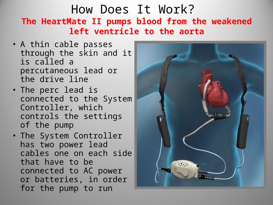
How Does It Work? The HeartMate II pumps blood from the weakened
left ventricle to the aorta
• A thin cable passes through the skin and it is called a percutaneous lead or the drive line
• The perc lead is connected to the System Controller, which controls the settings of the pump
• The System Controller has two power lead cables one on each side that have to be connected to AC power or batteries, in order for the pump to run
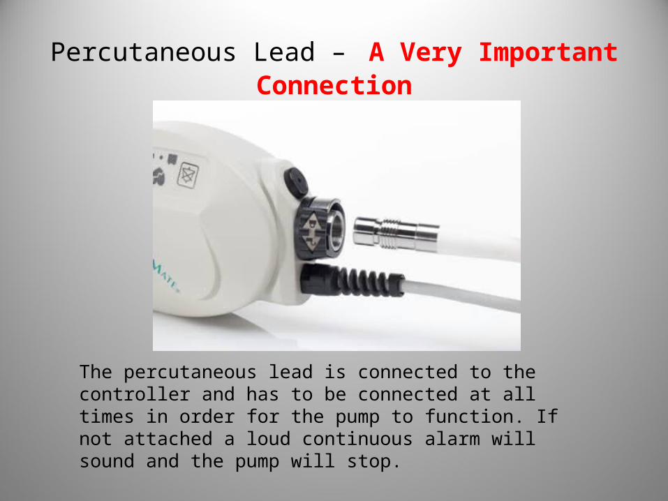
Percutaneous Lead – A Very Important Connection
The percutaneous lead is connected to the controller and has to be connected at all times in order for the pump to function. If not attached a loud continuous alarm will sound and the pump will stop.

Percutaneous Lead Lock
Unlocked Locked
The System Controller’s Perc Lock keeps the percutaneous lead from accidentally disconnecting from the Controller. When assessing your patient always check to make sure it is in the locked position

Perc Lead/Driveline
• The perc lead is the connection from the pump on the inside of the body to the system controller that is on the outside.
• Do not pull or move lead through the patient’s skin.• Patient should wear an abdominal binder or restrictive
device to keep the perc lead/driveline from moving.• It is extremely important to protect the perc lead since
damage to the lead can cause the pump to stop • Do not severely bend, kink, or twist the lead or catch it in
the carrying case zipper.• Do not let the lead catch or snag on anything that could
pull or move the lead.• At all times there should be a sterile dressing over the
perc lead where it exits out of the abdomen, and that area assessed daily for redness, discharge, heat, and moisture
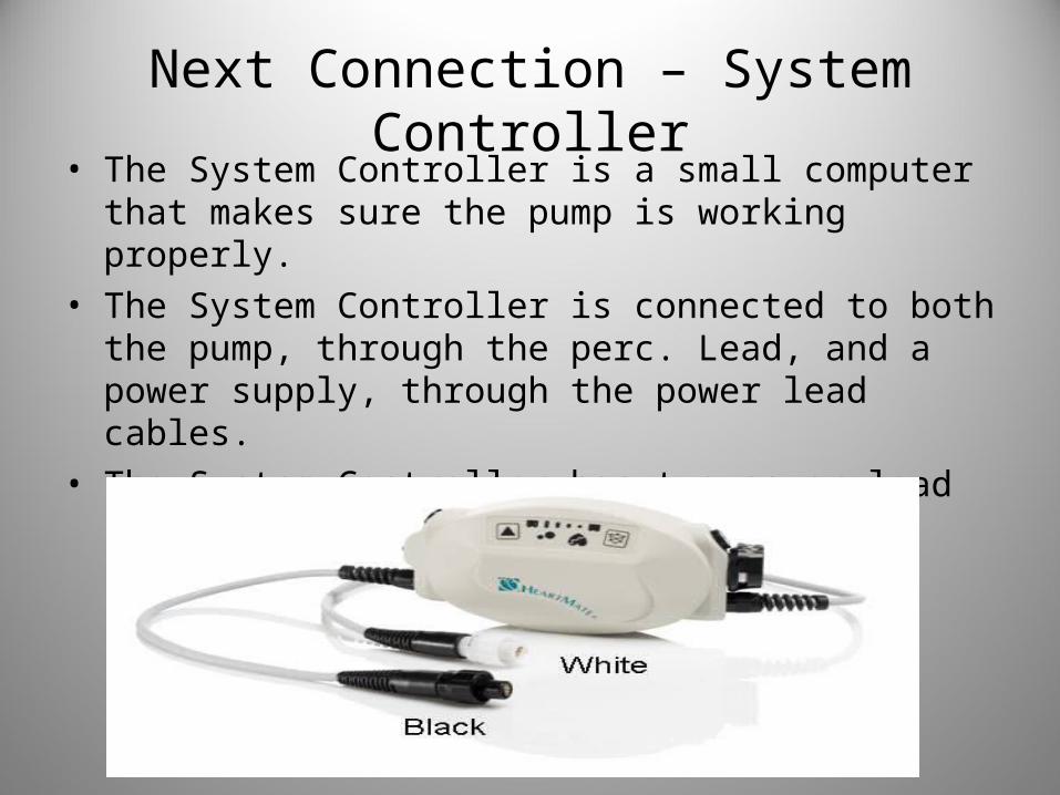
Next Connection – System Controller• The System Controller is a small computer that makes
sure the pump is working properly. • The System Controller is connected to both the pump,
through the perc. Lead, and a power supply, through the power lead cables.
• The System Controller has two power lead cables that are connected to a power source at all times
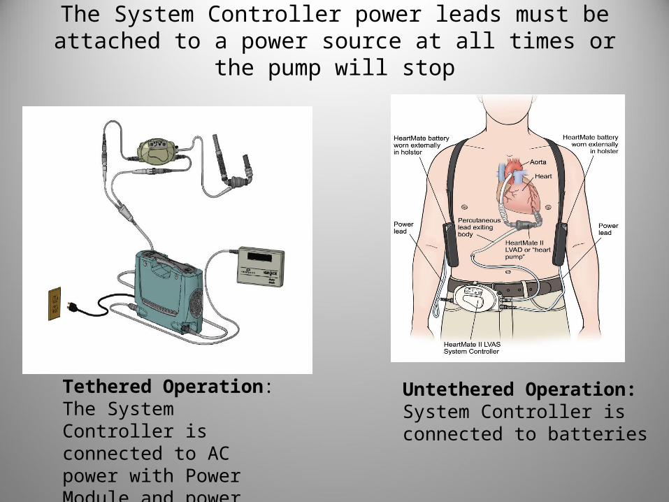
The System Controller power leads must be attached to a power source at all times or the pump will stop
Tethered Operation: The System Controller is connected to AC power with Power Module and power cable
Untethered Operation: System Controller is connected to batteries

Power Module (AC Power): Tethered Mode
Patient should ALWAYS connect to AC electrical power through the Power Module (PM) for sleep or when anticipating sleep.
Power Module/patient cable. This unit is plugged into a designated and grounded 3 prong socket
System Controller connected to patient cable/Power Module

Battery Power: Untethered Mode
• Battery power allows the patient to be mobile• Two batteries are attached to system controller• Each pair of batteries will last 6 – 10 hours• Equipment can be carried several different ways
Holster vestShoulder bag

Making Connections When Changing Power Sources
• Line up the half circles inside the connectors• Gently bring the connectors together, turning them slightly to make
the connection, if needed• When you feel the connectors engage, push them together firmly
until fully connected – WITHOUT twisting or forcing the connectors• Once they are fully connected, secure the connection between the
connectors by turning the nut on the connector. Hand tighten the nut; DO NOT use tools such as hemostats to tighten the connection.
• Never disconnect both at the same time or the PUMP WILL STOP

Changing from Power Module to Batteries
• Place two battery clips, two charged batteries, and the white and black Power Module to System Controller cables within easy reach.
• Place the 1st charged battery into a battery clip by lining up the arrows on the battery and battery clip and pushing until the battery clicks into place.
• Repeat step 2 for the 2nd battery/battery clip.

Changing power cable to battery• Unscrew the black System Controller patient cable connector
from the Power Base Module (PBU) connecter cable. The power disconnected alarm will come on: an alarm will sound one beep per second, the green power symbol will flash rapidly, and the four green battery fuel gauge lights will flash.
• Put aside the PBU patient cable connector that is connected to the Power Module; then connect the battery clip connector to the black System Controller connector.
One side of the cable will be connected to the PBM and the other to the system controller

Changing power cable to battery con’t
• When the alarms have stopped, unscrew the white System Controller patient cable connector from the Power Base Module (PBU) cable connector. The power disconnected alarm will come on: an alarm will sound one beep per second, the green power symbol will flash rapidly, and the four green battery fuel gauge lights will flash.
• Put aside the PBU patient cable connector; then connect the battery clip connector to the white system controller connector.
• Place the battery clips and batteries into the holsters or carrying case.
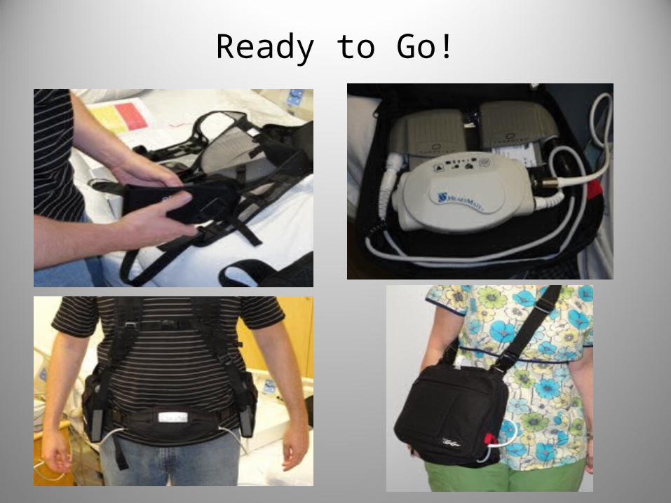
Ready to Go!

Changing from Battery Power to Power Module
• First step make sure the PM is plugged into AC power and the connectors are within reach. Next check the battery status on each battery. If one battery has less of a charge you want to change from that battery to the power module cable first. If both batteries have equal charge change the white cable first.

Changing from Battery Power to Power Module Cont.
• Unscrew the white system controller connector from the battery clip. The power disconnected alarm will come on: an alarm will sound one beep per second, the green power symbol will flash rapidly, and the four green battery fuel gauge lights will flash. * Remember the patient is still attached to the 2nd battery so the pump is still running. The alarm is there to remind you that you need to connect to a power source.
• Connect the white system controller connector to the white Power Module patient cable connector
• After alarm has stopped unscrew the black system controller connector from the battery clip. The power disconnected alarm will come on: an alarm will sound one beep per second, the green power symbol will flash rapidly, and the four green battery fuel gauge lights will flash.
• Connect the black system controller connector to the white Power Module patient cable. The patient is now connected to AC power.

Special Considerations When Caring for VAD Patients

Safety• Keep all LVAD equipment
away from water. If it gets wet it could cause the device to stop or one may receive a strong electric shock. The patient may take showers if approved by their doctor and they have a GoGear shower bag, which keeps the equipment dry!!! GoGear Shower Bag
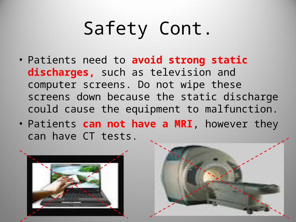
Safety Cont.
• Patients need to avoid strong static discharges, such as television and computer screens. Do not wipe these screens down because the static discharge could cause the equipment to malfunction.
• Patients can not have a MRI, however they can have CT tests.

The Black Bag
VAD PATIENTS ARE REQUIRED TO CARRY A BAG WITH THEM AT ALL TIMES WHICH CONTAINS:
• Extra System Controller
• Extra Fully Charged Batteries
• Extra Battery Clips
• Emergency Contacts

Alarms
• The System Controller warns you if there is a problem with the pump or its power supply.
• The Controller’s warning lights, buttons, and battery fuel gauge are on the top of the device
Test Select Button
Battery FuelGauge
Battery Symbol(yellow and red)
SilenceAlarmButton
PowerSymbol(green)
ControllerCell Symbol(yellow)
RedHeartSymbol
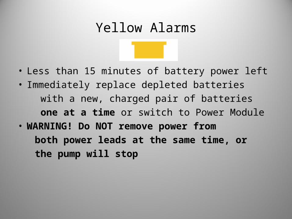
Yellow Alarms
• Less than 15 minutes of battery power left• Immediately replace depleted batteries
with a new, charged pair of batteries
one at a time or switch to Power Module• WARNING! Do NOT remove power from
both power leads at the same time, or
the pump will stop
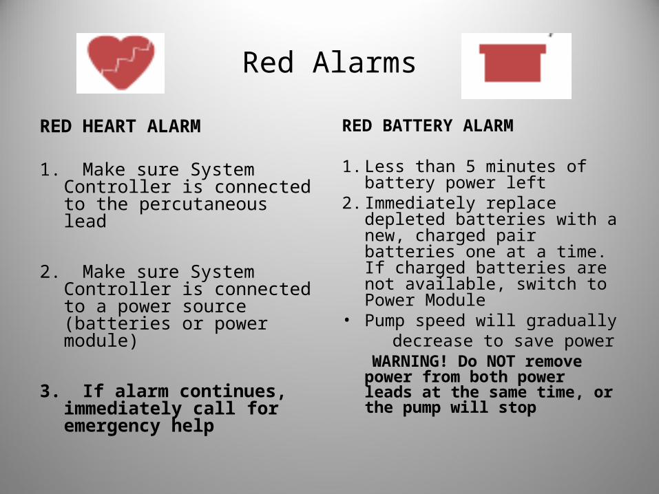
Red Alarms
RED HEART ALARM
1. Make sure System Controller is connected to the percutaneous lead
2. Make sure System Controller is connected to a power source (batteries or power module)
3. If alarm continues, immediately call for emergency help
RED BATTERY ALARM
1. Less than 5 minutes of battery power left
2. Immediately replace depleted batteries with a new, charged pair batteries one at a time. If charged batteries are not available, switch to Power Module
• Pump speed will gradually decrease to save power WARNING! Do NOT remove
power from both power leads at the same time, or the pump will stop
Important Clinical Info
• Non-pulstatile VAD patients – are typically pulseless as this is a continuous flow device.
• Assess the patient for signs of good circulation to determine if perfusion is adequate, such as capillary refill and their mentation.
• Automatic blood pressures are not accurate and usually can’t be obtained as pts do not have systolic or diastolic function due to continuous flow provided by VAD.
• Blood pressure must be measured by manual cuff with doppler; when you hear the swooshing sound that will be your Mean Arterial Pressure (MAP). You want the MAP between 60-90.
• May be difficult to obtain an O2 sat due to lack of pulsatility so you have to get a blood gas if you are concerned of low O2
• Pts are anti-coagulated on Coumadin and aspirin and are at risk for bleeding.
Emergency Procedures
• An emergency exists when the device is potentially or actually unable to pump an adequate amount of blood. These conditions are signified by a RED HEART SYMBOL and accompanied by a CONTINUOUS AUDIO TONE.
• In the event the VAD stops operating, all attempts must be made to restore pump function immediately by:– Checking the percutaneous lead connection to the
system controller– Make sure system controller is connected to a power
source– If alarm continues, immediately call Rapid
Response 25900, then page Dr. Bensimhon and if can’t get him then Dr. VanTrigt
NO CPR!
Remember……..
•A trained VAD nurse must remain with the patient at all times. When traveling the VAD nurse needs to make sure they have the patients equipment: backup System Controller, back up charged Batteries, and back up Battery Clips•VAD equipment may not work properly if it gets wet – protect from moisture•Any questions – Call Rapid Response 25900

Summary
• There will be more extensive training for managing and taking care of these patients soon.
• Any questions email the VAD Coordinator at [email protected]
• For more info refer to homepage/resources/refdocs/clinical resources/criticalcare/Thoratec folder/HeartMate