hd 10/25 s hd 13/18 s service manual - karcher-marine.com · this service manual describes the...
TRANSCRIPT
English 5.905-945.0 Rev. 00 (06/15) 1
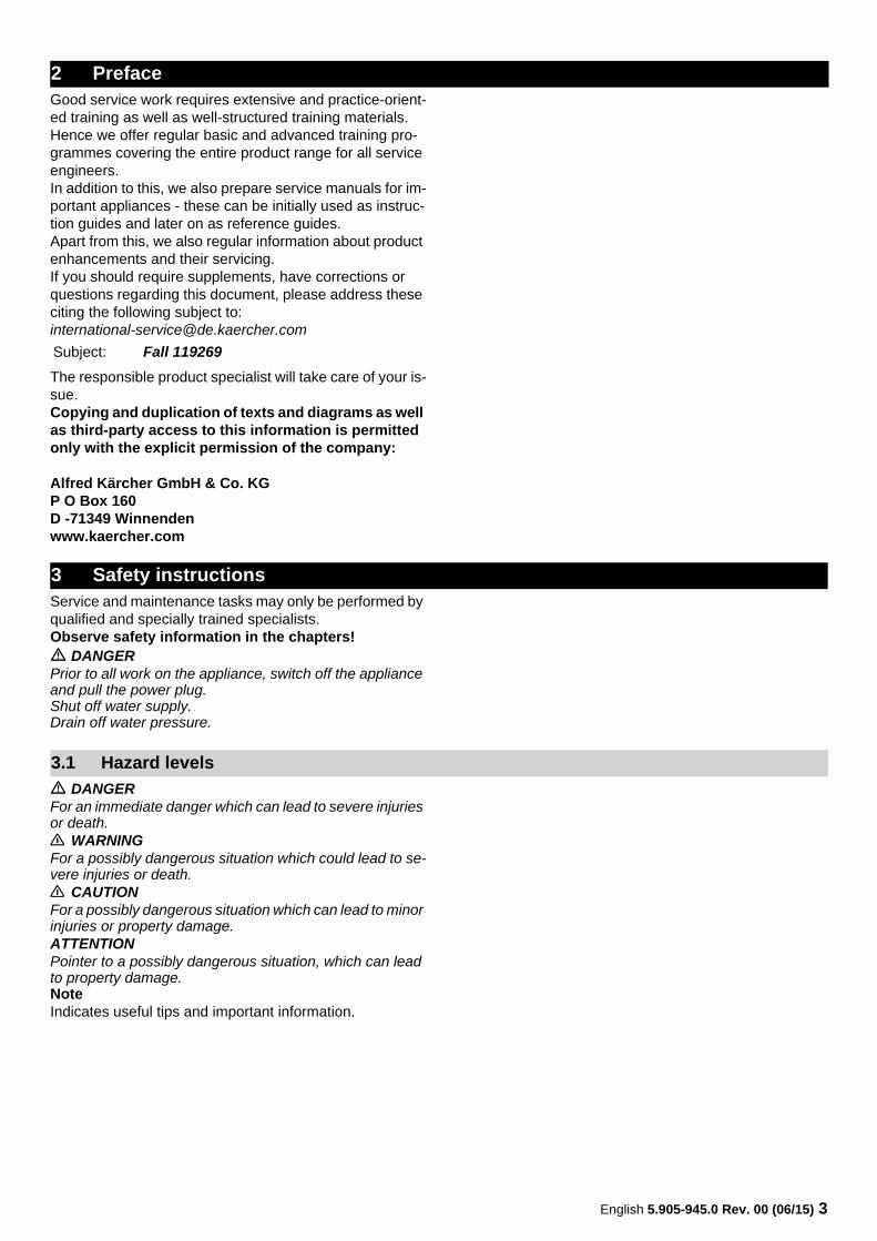
HD 10/25 SHD 13/18 SService Manual
2 English 5.905-945.0 Rev. 00 (06/15)
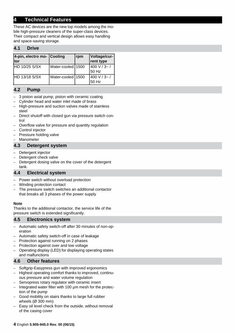
1 Contents
2 Preface 33 Safety instructions 3
3.1 Hazard levels 3
4 Technical Features 44.1 Drive 44.2 Pump 44.3 Detergent system 44.4 Electrical system 44.5 Electronics system 44.6 Other features 44.7 Field of application 54.8 Type plate 5
5 Parts of the system 65.1 Front view 65.2 View from behind 75.3 View from below 85.4 Front view (without cover) 95.5 Front view (electric box opened) 10
6 Function 116.1 Motor/pump unit 116.2 Water filter 116.3 Pump diagram 126.4 Hand spraygun 156.5 Pressure and volume regulation 166.6 Triple nozzle 176.7 Electronics system 18
6.7.1 Pump monitoring 186.7.2 Leakage monitoring 186.7.3 Motor protection 186.7.4 Display 186.7.5 Reset 196.7.6 Setting the DIP switches 19
6.8 Bypass valve 20
7 Basic settings and service procedures 217.1 Adjusting the overflow valve 217.2 Trigger gun with servopress pressure regulator 217.3 Trigger gun standard 217.4 Hose drum 22
7.4.1 Remove the hose drum 227.4.2 Uninstall / install high-pressure hose 227.4.3 Replace the seal of the rotary grommet 23
8 Troubleshooting 259 Technical Documentation 26
9.1 Technical specifications 26
10 Special tools 2711 Circuit diagram 2912 Torques 30
English 5.905-945.0 Rev. 00 (06/15) 3
Good service work requires extensive and practice-orient-ed training as well as well-structured training materials.Hence we offer regular basic and advanced training pro-grammes covering the entire product range for all service engineers.In addition to this, we also prepare service manuals for im-portant appliances - these can be initially used as instruc-tion guides and later on as reference guides.Apart from this, we also regular information about product enhancements and their servicing.If you should require supplements, have corrections or questions regarding this document, please address these citing the following subject to:[email protected]
The responsible product specialist will take care of your is-sue.Copying and duplication of texts and diagrams as well as third-party access to this information is permitted only with the explicit permission of the company:
Alfred Kärcher GmbH & Co. KGP O Box 160D -71349 Winnendenwww.kaercher.com
Service and maintenance tasks may only be performed by qualified and specially trained specialists.Observe safety information in the chapters!� DANGERPrior to all work on the appliance, switch off the appliance and pull the power plug.Shut off water supply.Drain off water pressure.
� DANGERFor an immediate danger which can lead to severe injuries or death.� WARNINGFor a possibly dangerous situation which could lead to se-vere injuries or death.� CAUTIONFor a possibly dangerous situation which can lead to minor injuries or property damage.ATTENTIONPointer to a possibly dangerous situation, which can lead to property damage.NoteIndicates useful tips and important information.
2 Preface
Subject: Fall 119269
3 Safety instructions
3.1 Hazard levels
4 English 5.905-945.0 Rev. 00 (06/15)
These AC devices are the new top models among the mo-bile high-pressure cleaners of the super-class devices. Their compact and vertical design allows easy handling and space-saving storage.
– 3 piston axial pump, piston with ceramic coating– Cylinder head and water inlet made of brass– High-pressure and suction valves made of stainless
steel– Direct shutoff with closed gun via pressure switch con-
trol– Overflow valve for pressure and quantity regulation– Control injector– Pressure holding valve– Manometer
– Detergent injector– Detergent check valve– Detergent dosing valve on the cover of the detergent
tank.
– Power switch without overload protection– Winding protection contact– The pressure switch switches an additional contactor
that breaks all 3 phases of the power supply
NoteThanks to the additional contactor, the service life of the pressure switch is extended significantly.
– Automatic safety switch-off after 30 minutes of non-op-eration
– Automatic safety switch-off in case of leakage– Protection against running on 2 phases– Protection against over and low voltage– Operating display (LED) for displaying operating states
and malfunctions
– Softgrip-Easypress gun with improved ergonomics– Highest operating comfort thanks to improved, continu-
ous pressure and water volume regulation– Servopress rotary regulator with ceramic insert– Integrated water filter with 100 μm mesh for the protec-
tion of the pump– Good mobility on stairs thanks to large full rubber
wheels (Ø 300 mm)– Easy oil level check from the outside, without removal
of the casing cover
4 Technical Features
4.1 Drive4-pin, electro mo-tor
Cooling rpm Voltage/cur-rent type
HD 10/25 S/SX Water-cooled 1500 400 V / 3~ / 50 Hz
HD 13/18 S/SX Water-cooled 1500 400 V / 3~ / 50 Hz
4.2 Pump
4.3 Detergent system
4.4 Electrical system
4.5 Electronics system
4.6 Other features
English 5.905-945.0 Rev. 00 (06/15) 5
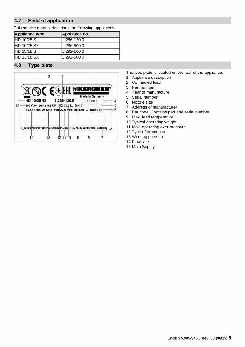
This service manual describes the following appliances:
The type plate is located on the rear of the appliance.1 Appliance description2 Connected load3 Part number4 Year of manufacture5 Serial number6 Nozzle size7 Address of manufacturer8 Bar code. Contains part and serial number.9 Max. feed temperature10 Typical operating weight11 Max. operating over-pressure12 Type of protection13 Working pressure14 Flow rate15 Main Supply
4.7 Field of application
Appliance type Appliance no.HD 10/25 S 1.286-120.0HD 10/25 SX 1.286-500.0HD 13/18 S 1.292-100.0HD 13/18 SX 1.292-500.0
4.8 Type plate
6 English 5.905-945.0 Rev. 00 (06/15)
5 Parts of the system
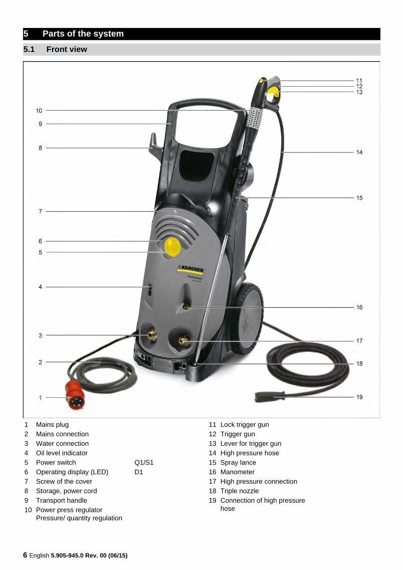
5.1 Front view
1 Mains plug2 Mains connection3 Water connection4 Oil level indicator5 Power switch Q1/S16 Operating display (LED) D17 Screw of the cover 8 Storage, power cord9 Transport handle10 Power press regulator
Pressure/ quantity regulation
11 Lock trigger gun12 Trigger gun13 Lever for trigger gun14 High pressure hose15 Spray lance16 Manometer17 High pressure connection18 Triple nozzle19 Connection of high pressure
hose
English 5.905-945.0 Rev. 00 (06/15) 7
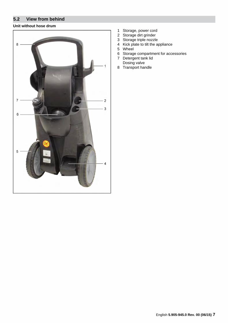
Unit without hose drum1 Storage, power cord2 Storage dirt grinder3 Storage triple nozzle4 Kick plate to tilt the appliance5 Wheel6 Storage compartment for accessories7 Detergent tank lid
Dosing valve8 Transport handle
5.2 View from behind
8 English 5.905-945.0 Rev. 00 (06/15)
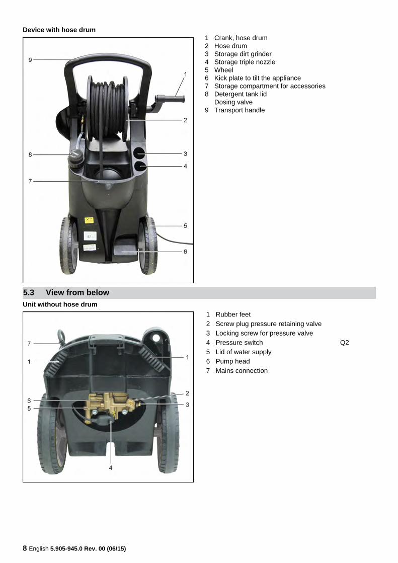
Device with hose drum1 Crank, hose drum2 Hose drum3 Storage dirt grinder4 Storage triple nozzle5 Wheel6 Kick plate to tilt the appliance7 Storage compartment for accessories8 Detergent tank lid
Dosing valve9 Transport handle
Unit without hose drum5.3 View from below
1 Rubber feet2 Screw plug pressure retaining valve3 Locking screw for pressure valve4 Pressure switch Q25 Lid of water supply6 Pump head7 Mains connection
English 5.905-945.0 Rev. 00 (06/15) 9
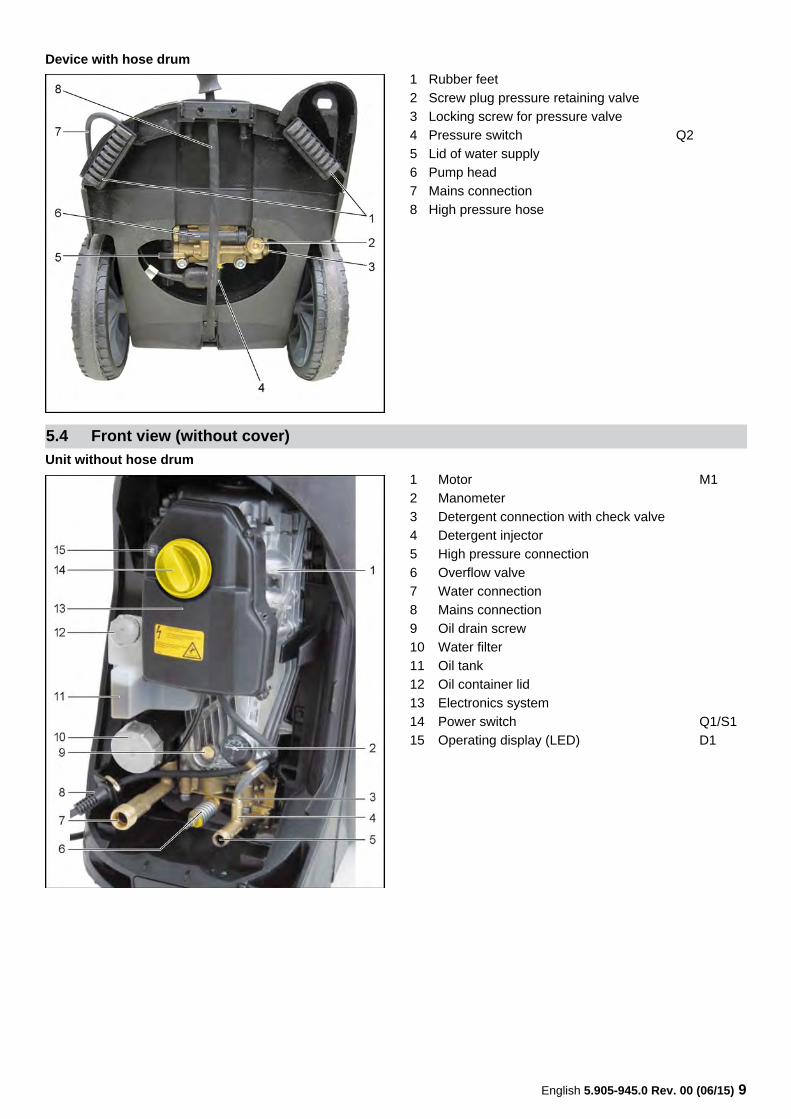
Device with hose drum
Unit without hose drum
1 Rubber feet2 Screw plug pressure retaining valve3 Locking screw for pressure valve4 Pressure switch Q25 Lid of water supply6 Pump head7 Mains connection8 High pressure hose
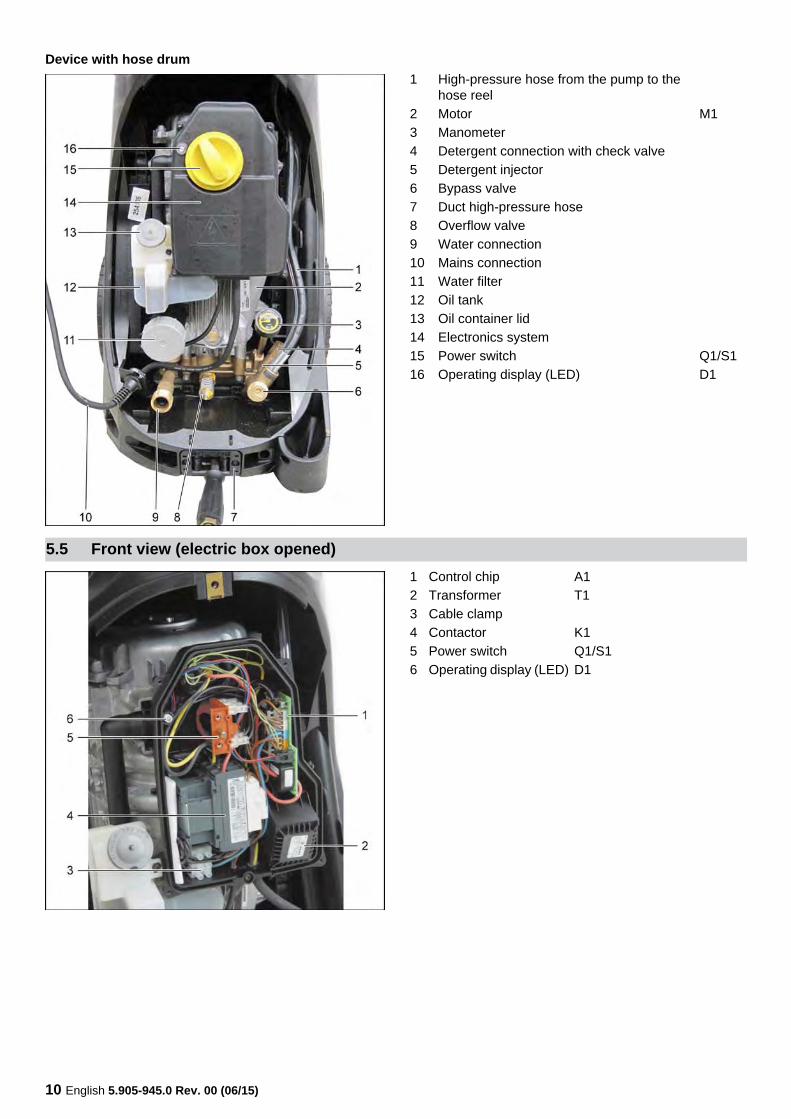
5.4 Front view (without cover)
1 Motor M12 Manometer3 Detergent connection with check valve4 Detergent injector5 High pressure connection6 Overflow valve7 Water connection8 Mains connection9 Oil drain screw10 Water filter11 Oil tank12 Oil container lid13 Electronics system14 Power switch Q1/S115 Operating display (LED) D1
10 English 5.905-945.0 Rev. 00 (06/15)
Device with hose drum1 High-pressure hose from the pump to the
hose reel2 Motor M13 Manometer4 Detergent connection with check valve5 Detergent injector6 Bypass valve7 Duct high-pressure hose8 Overflow valve9 Water connection10 Mains connection11 Water filter12 Oil tank13 Oil container lid14 Electronics system15 Power switch Q1/S116 Operating display (LED) D1
5.5 Front view (electric box opened)1 Control chip A12 Transformer T13 Cable clamp4 Contactor K15 Power switch Q1/S16 Operating display (LED) D1
English 5.905-945.0 Rev. 00 (06/15) 11
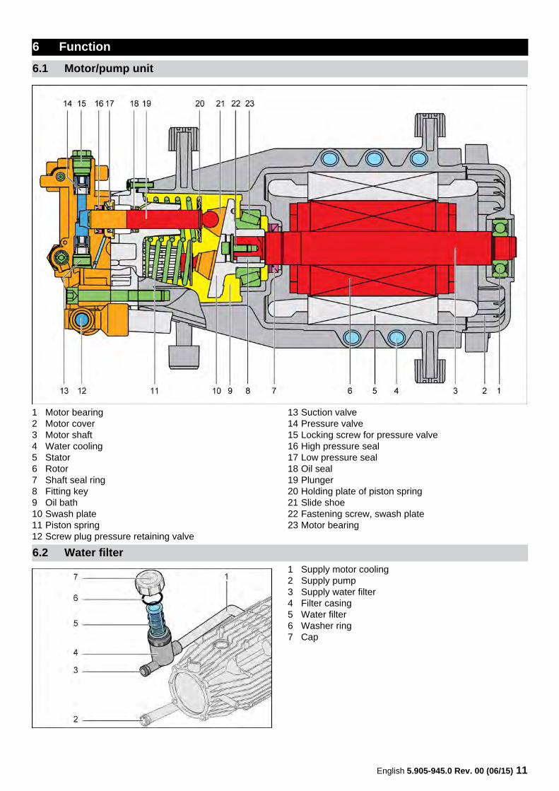
1 Motor bearing2 Motor cover3 Motor shaft4 Water cooling5 Stator6 Rotor7 Shaft seal ring8 Fitting key9 Oil bath10 Swash plate11 Piston spring12 Screw plug pressure retaining valve
13 Suction valve14 Pressure valve15 Locking screw for pressure valve16 High pressure seal17 Low pressure seal18 Oil seal19 Plunger20 Holding plate of piston spring21 Slide shoe22 Fastening screw, swash plate23 Motor bearing
1 Supply motor cooling2 Supply pump3 Supply water filter4 Filter casing5 Water filter6 Washer ring7 Cap
6 Function
6.1 Motor/pump unit
6.2 Water filter
12 English 5.905-945.0 Rev. 00 (06/15)
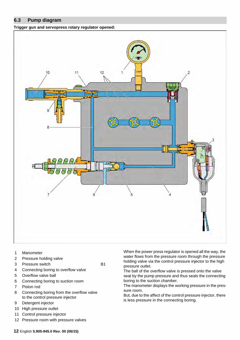
Trigger gun and servopress rotary regulator opened:
When the power press regulator is opened all the way, the water flows from the pressure room through the pressure holding valve via the control pressure injector to the high pressure outlet.The ball of the overflow valve is pressed onto the valve seat by the pump pressure and thus seals the connecting boring to the suction chamber.The manometer displays the working pressure in the pres-sure room.But, due to the affect of the control pressure injector, there is less pressure in the connecting boring.
6.3 Pump diagram
1 Manometer2 Pressure holding valve3 Pressure switch B14 Connecting boring to overflow valve5 Overflow valve ball6 Connecting boring to suction room7 Piston rod8 Connecting boring from the overflow valve
to the control pressure injector9 Detergent injector10 High pressure outlet11 Control pressure injector12 Pressure room with pressure valves
English 5.905-945.0 Rev. 00 (06/15) 13
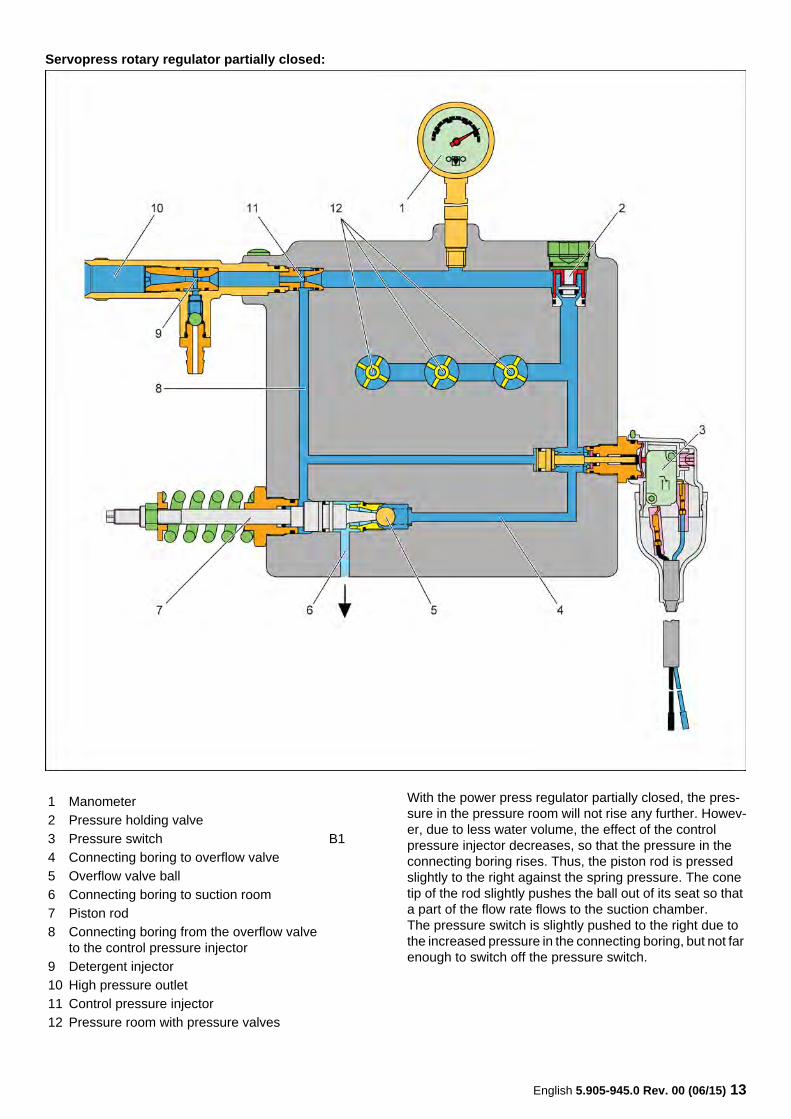
Servopress rotary regulator partially closed:
With the power press regulator partially closed, the pres-sure in the pressure room will not rise any further. Howev-er, due to less water volume, the effect of the control pressure injector decreases, so that the pressure in the connecting boring rises. Thus, the piston rod is pressed slightly to the right against the spring pressure. The cone tip of the rod slightly pushes the ball out of its seat so that a part of the flow rate flows to the suction chamber.The pressure switch is slightly pushed to the right due to the increased pressure in the connecting boring, but not far enough to switch off the pressure switch.
1 Manometer2 Pressure holding valve3 Pressure switch B14 Connecting boring to overflow valve5 Overflow valve ball6 Connecting boring to suction room7 Piston rod8 Connecting boring from the overflow valve
to the control pressure injector9 Detergent injector10 High pressure outlet11 Control pressure injector12 Pressure room with pressure valves
14 English 5.905-945.0 Rev. 00 (06/15)
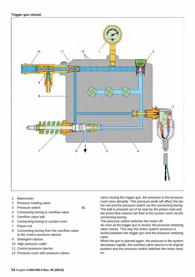
Trigger gun closed:
Upon closing the trigger gun, the pressure in the pressure room rises abruptly. This pressure peak will affect the pis-ton rod and the pressure switch via the connecting boring. The ball is pressed out of its seat by the piston road and the entire flow volume can flow to the suction room via the connecting boring.The pressure switch switches the motor off.As soon as the trigger gun is closed, the pressure retaining valve closes. This way the entire system pressure is locked between the trigger gun and the pressure retaining valve.When the gun is opened again, the pressure in the system decreases rapidly, the overflow valve returns to its original position and the pressure switch switches the motor back on.
1 Manometer2 Pressure holding valve3 Pressure switch B14 Connecting boring to overflow valve5 Overflow valve ball6 Connecting boring to suction room7 Piston rod8 Connecting boring from the overflow valve
to the control pressure injector9 Detergent injector10 High pressure outlet11 Control pressure injector12 Pressure room with pressure valves
English 5.905-945.0 Rev. 00 (06/15) 15
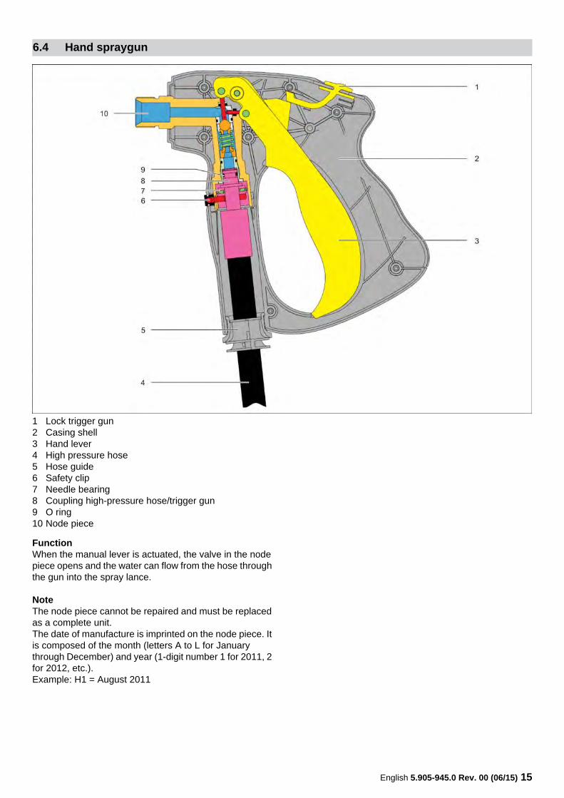
1 Lock trigger gun2 Casing shell3 Hand lever4 High pressure hose5 Hose guide6 Safety clip7 Needle bearing8 Coupling high-pressure hose/trigger gun9 O ring10 Node piece
FunctionWhen the manual lever is actuated, the valve in the node piece opens and the water can flow from the hose through the gun into the spray lance.
NoteThe node piece cannot be repaired and must be replaced as a complete unit.The date of manufacture is imprinted on the node piece. It is composed of the month (letters A to L for January through December) and year (1-digit number 1 for 2011, 2 for 2012, etc.).Example: H1 = August 2011
6.4 Hand spraygun
16 English 5.905-945.0 Rev. 00 (06/15)
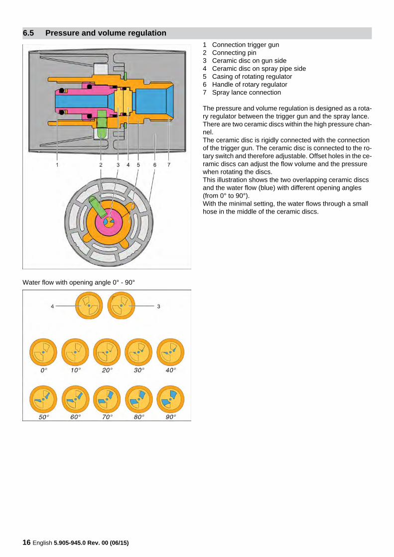
1 Connection trigger gun2 Connecting pin3 Ceramic disc on gun side4 Ceramic disc on spray pipe side5 Casing of rotating regulator6 Handle of rotary regulator7 Spray lance connection
The pressure and volume regulation is designed as a rota-ry regulator between the trigger gun and the spray lance.There are two ceramic discs within the high pressure chan-nel.The ceramic disc is rigidly connected with the connection of the trigger gun. The ceramic disc is connected to the ro-tary switch and therefore adjustable. Offset holes in the ce-ramic discs can adjust the flow volume and the pressure when rotating the discs.This illustration shows the two overlapping ceramic discs and the water flow (blue) with different opening angles (from 0° to 90°).With the minimal setting, the water flows through a small hose in the middle of the ceramic discs.
Water flow with opening angle 0° - 90°
6.5 Pressure and volume regulation
English 5.905-945.0 Rev. 00 (06/15) 17
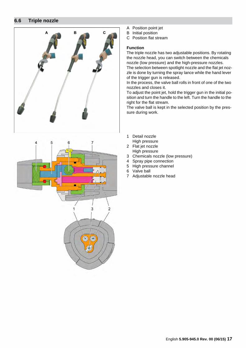
A Position point jetB Initial positionC Position flat stream
FunctionThe triple nozzle has two adjustable positions. By rotating the nozzle head, you can switch between the chemicals nozzle (low pressure) and the high-pressure nozzles.The selection between spotlight nozzle and the flat jet noz-zle is done by turning the spray lance while the hand lever of the trigger gun is released.In the process, the valve ball rolls in front of one of the two nozzles and closes it.To adjust the point jet, hold the trigger gun in the initial po-sition and turn the handle to the left. Turn the handle to the right for the flat stream.The valve ball is kept in the selected position by the pres-sure during work.
1 Detail nozzleHigh pressure
2 Flat jet nozzleHigh pressure
3 Chemicals nozzle (low pressure)4 Spray pipe connection5 High pressure channel6 Valve ball7 Adjustable nozzle head
6.6 Triple nozzle
18 English 5.905-945.0 Rev. 00 (06/15)
The device is equipped with a control and monitoring elec-tronic system that monitors a number of functions.
In case of a continuous operation or a continuous break of 30 minutes, the immediate switch-off and locking of the de-vice takes place.Moreover, a visual signal is issued via the operating dis-play (LED).Both functions can be deactivated by means of the DIP switch (see circuit diagram).
The system checks the device for leaks by monitoring the pressure switch. If the pressure switch opens twice within 2 seconds and this recurs 10 times within 10 minutes, the immediate switch-off and locking of the device takes place.Moreover, a visual signal is issued via the operating dis-play (LED).This function can be deactivated by means of the DIP switch (see circuit diagram).
If one phase fails, in case of excessive temperature, low voltage or in case of a voltage difference between 2 phas-es > 50 V, the immediate switch-off and locking of the de-vice takes place.Moreover, a visual signal is issued via the operating dis-play (LED).The excess temperature may occur due to the following reasons:– Over or low voltage– Overload– Poor motor cooling (water shortage or high tempera-
ture of the cooling water)
Operating display:
Error message:
6.7 Electronics system
6.7.1 Pump monitoring
6.7.2 Leakage monitoring
6.7.3 Motor protection
6.7.4 Display
LED illuminates green
Operation in order
LED blinks green Disconnection from the mains (time-out)
LED is red Contactor or pressure switch not in order
LED blinks red once LeakLED blinks red twice Winding protection contact was trig-
geredLED blinks red three times
Power supply
LED blinks red four times
Power consumption is too highEnd motor blockade
English 5.905-945.0 Rev. 00 (06/15) 19
The resetting of the system in case of faults takes place by switching on and off the power switch.
6.7.5 Reset
6.7.6 Setting the DIP switchesON OFF
1 1-phase device 3-phase device2 Do not use No after run of the pump3 Leakage monitoring No monitoring4 30 minutes switch-off continuous operation / continu-
ous pauseNo switch-off
20 English 5.905-945.0 Rev. 00 (06/15)
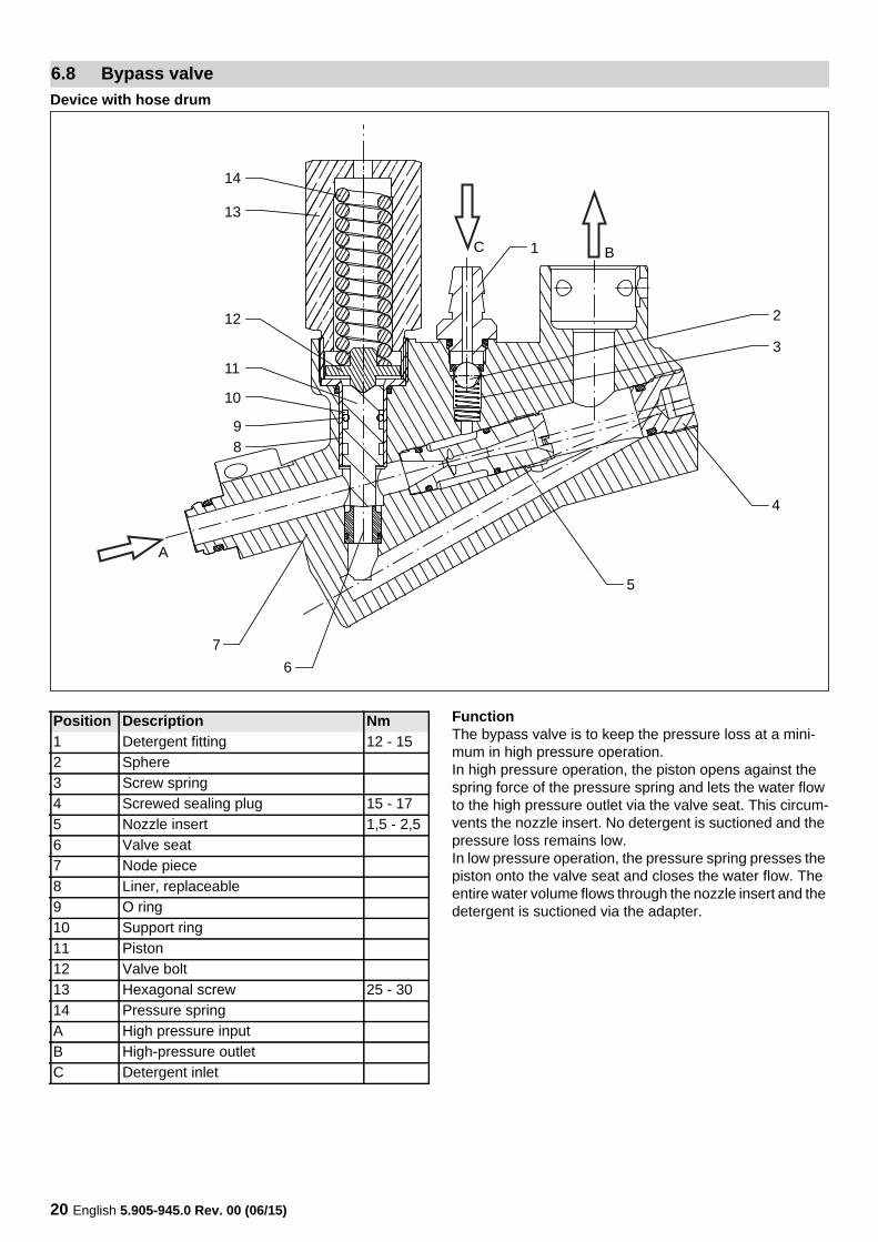
Device with hose drum
FunctionThe bypass valve is to keep the pressure loss at a mini-mum in high pressure operation.In high pressure operation, the piston opens against the spring force of the pressure spring and lets the water flow to the high pressure outlet via the valve seat. This circum-vents the nozzle insert. No detergent is suctioned and the pressure loss remains low.In low pressure operation, the pressure spring presses the piston onto the valve seat and closes the water flow. The entire water volume flows through the nozzle insert and the detergent is suctioned via the adapter.
6.8 Bypass valve
1
2
3
5
4
67
89
11
10
12
13
14
B
A
C
Position Description Nm1 Detergent fitting 12 - 152 Sphere3 Screw spring4 Screwed sealing plug 15 - 175 Nozzle insert 1,5 - 2,56 Valve seat7 Node piece8 Liner, replaceable9 O ring10 Support ring11 Piston12 Valve bolt13 Hexagonal screw 25 - 3014 Pressure springA High pressure inputB High-pressure outletC Detergent inlet
English 5.905-945.0 Rev. 00 (06/15) 21
� DANGERPrior to all work on the appliance, switch off the appliance and pull the power plug.Shut off water supply.Drain off water pressure.
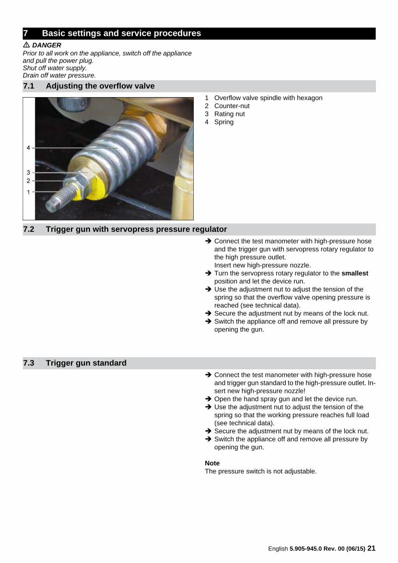
1 Overflow valve spindle with hexagon2 Counter-nut3 Rating nut4 Spring
Connect the test manometer with high-pressure hose and the trigger gun with servopress rotary regulator to the high pressure outlet.Insert new high-pressure nozzle.
Turn the servopress rotary regulator to the smallest position and let the device run.
Use the adjustment nut to adjust the tension of the spring so that the overflow valve opening pressure is reached (see technical data).
Secure the adjustment nut by means of the lock nut. Switch the appliance off and remove all pressure by
opening the gun.
Connect the test manometer with high-pressure hose and trigger gun standard to the high-pressure outlet. In-sert new high-pressure nozzle!
Open the hand spray gun and let the device run. Use the adjustment nut to adjust the tension of the
spring so that the working pressure reaches full load (see technical data).
Secure the adjustment nut by means of the lock nut. Switch the appliance off and remove all pressure by
opening the gun.
NoteThe pressure switch is not adjustable.
7 Basic settings and service procedures
7.1 Adjusting the overflow valve
7.2 Trigger gun with servopress pressure regulator
7.3 Trigger gun standard
22 English 5.905-945.0 Rev. 00 (06/15)
Device with hose drum
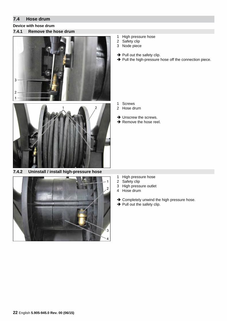
1 High pressure hose2 Safety clip3 Node piece
Pull out the safety clip. Pull the high-pressure hose off the connection piece.
1 Screws2 Hose drum
Unscrew the screws. Remove the hose reel.
1 High pressure hose2 Safety clip3 High pressure outlet4 Hose drum
Completely unwind the high pressure hose. Pull out the safety clip.
7.4 Hose drum
7.4.1 Remove the hose drum
7.4.2 Uninstall / install high-pressure hose
English 5.905-945.0 Rev. 00 (06/15) 23
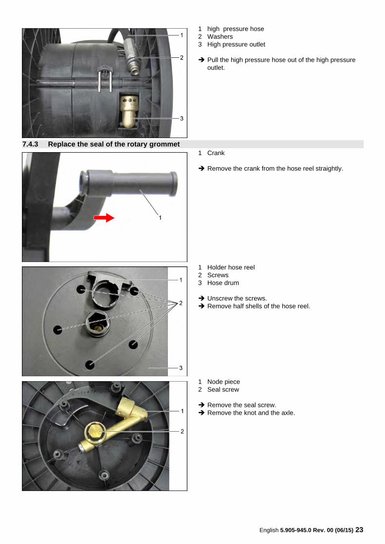
1 high pressure hose 2 Washers3 High pressure outlet
Pull the high pressure hose out of the high pressure outlet.
1 Crank
Remove the crank from the hose reel straightly.
1 Holder hose reel2 Screws3 Hose drum
Unscrew the screws. Remove half shells of the hose reel.
1 Node piece2 Seal screw
Remove the seal screw. Remove the knot and the axle.
7.4.3 Replace the seal of the rotary grommet
24 English 5.905-945.0 Rev. 00 (06/15)
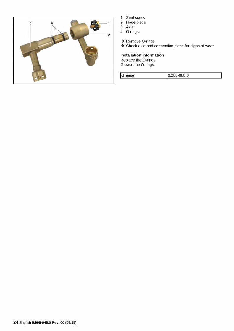
1 Seal screw2 Node piece3 Axle4 O rings
Remove O-rings. Check axle and connection piece for signs of wear.
Installation informationReplace the O-rings.Grease the O-rings.
Grease 6.288-088.0
English 5.905-945.0 Rev. 00 (06/15) 25
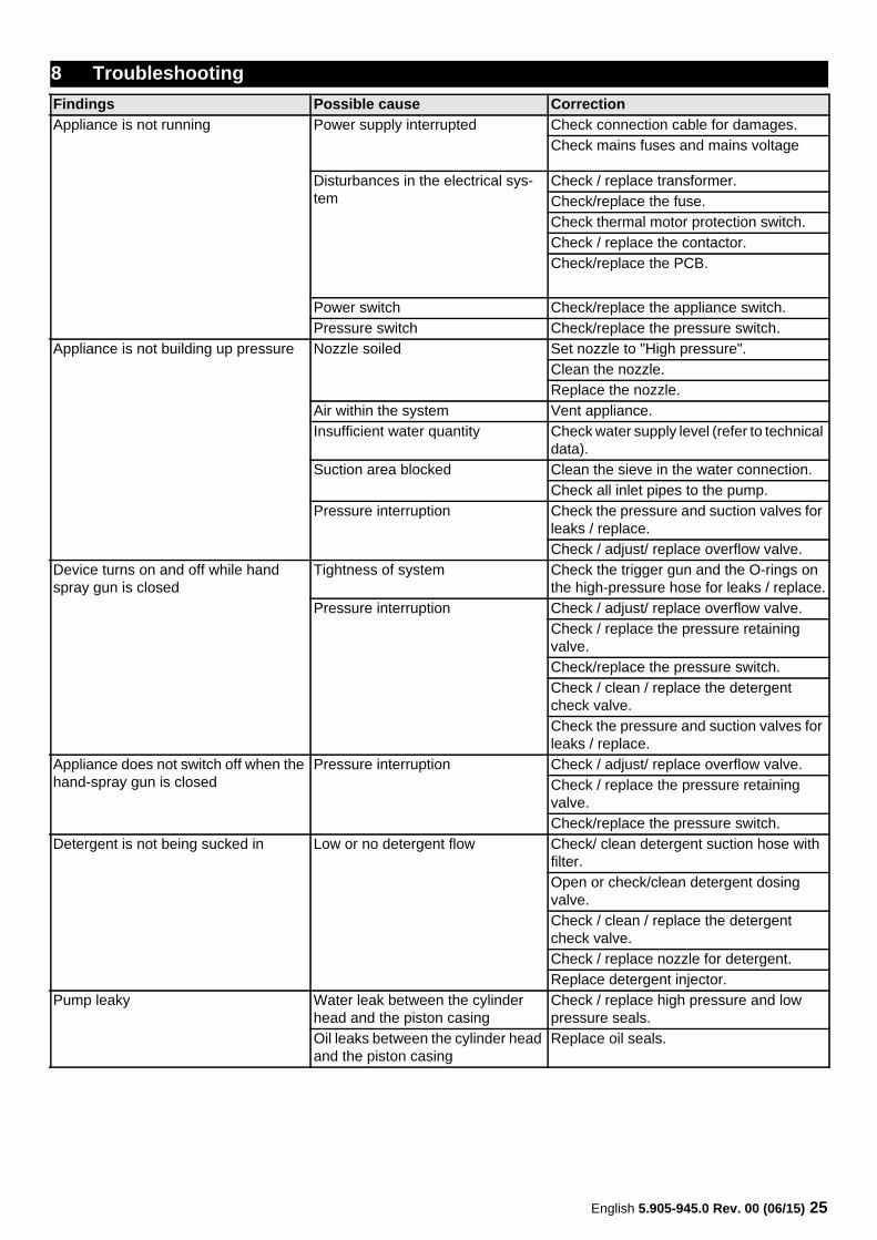
8 TroubleshootingFindings Possible cause CorrectionAppliance is not running Power supply interrupted Check connection cable for damages.
Check mains fuses and mains voltage
Disturbances in the electrical sys-tem
Check / replace transformer.Check/replace the fuse.Check thermal motor protection switch.Check / replace the contactor.Check/replace the PCB.
Power switch Check/replace the appliance switch.Pressure switch Check/replace the pressure switch.
Appliance is not building up pressure Nozzle soiled Set nozzle to "High pressure". Clean the nozzle.Replace the nozzle.
Air within the system Vent appliance.Insufficient water quantity Check water supply level (refer to technical
data).Suction area blocked Clean the sieve in the water connection.
Check all inlet pipes to the pump. Pressure interruption Check the pressure and suction valves for
leaks / replace.Check / adjust/ replace overflow valve.
Device turns on and off while hand spray gun is closed
Tightness of system Check the trigger gun and the O-rings on the high-pressure hose for leaks / replace.
Pressure interruption Check / adjust/ replace overflow valve.Check / replace the pressure retaining valve.Check/replace the pressure switch.Check / clean / replace the detergent check valve.Check the pressure and suction valves for leaks / replace.
Appliance does not switch off when the hand-spray gun is closed
Pressure interruption Check / adjust/ replace overflow valve.Check / replace the pressure retaining valve.Check/replace the pressure switch.
Detergent is not being sucked in Low or no detergent flow Check/ clean detergent suction hose with filter. Open or check/clean detergent dosing valve. Check / clean / replace the detergent check valve.Check / replace nozzle for detergent.Replace detergent injector.
Pump leaky Water leak between the cylinder head and the piston casing
Check / replace high pressure and low pressure seals.
Oil leaks between the cylinder head and the piston casing
Replace oil seals.
26 English 5.905-945.0 Rev. 00 (06/15)
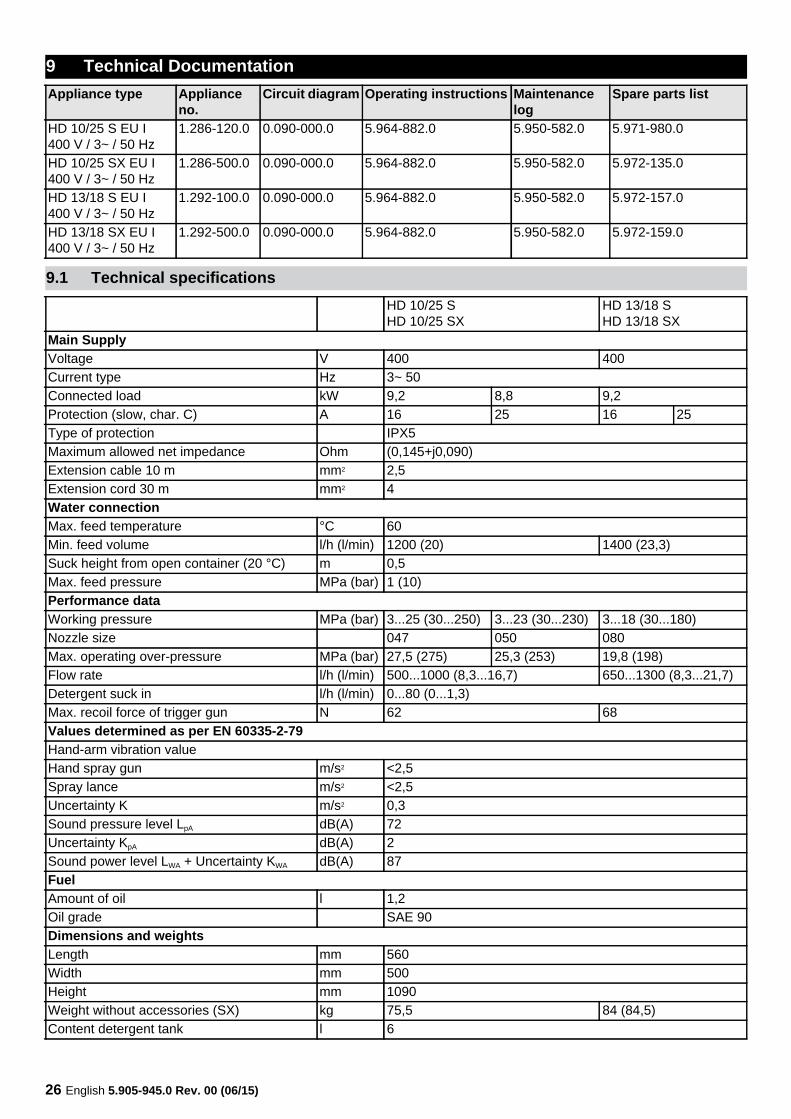
9 Technical DocumentationAppliance type Appliance
no.Circuit diagram Operating instructions Maintenance
logSpare parts list
HD 10/25 S EU I400 V / 3~ / 50 Hz
1.286-120.0 0.090-000.0 5.964-882.0 5.950-582.0 5.971-980.0
HD 10/25 SX EU I400 V / 3~ / 50 Hz
1.286-500.0 0.090-000.0 5.964-882.0 5.950-582.0 5.972-135.0
HD 13/18 S EU I400 V / 3~ / 50 Hz
1.292-100.0 0.090-000.0 5.964-882.0 5.950-582.0 5.972-157.0
HD 13/18 SX EU I400 V / 3~ / 50 Hz
1.292-500.0 0.090-000.0 5.964-882.0 5.950-582.0 5.972-159.0
9.1 Technical specificationsHD 10/25 SHD 10/25 SX
HD 13/18 SHD 13/18 SX
Main SupplyVoltage V 400 400Current type Hz 3~ 50Connected load kW 9,2 8,8 9,2Protection (slow, char. C) A 16 25 16 25Type of protection IPX5Maximum allowed net impedance Ohm (0,145+j0,090)Extension cable 10 m mm2 2,5Extension cord 30 m mm2 4Water connectionMax. feed temperature °C 60Min. feed volume l/h (l/min) 1200 (20) 1400 (23,3)Suck height from open container (20 °C) m 0,5Max. feed pressure MPa (bar) 1 (10)Performance dataWorking pressure MPa (bar) 3...25 (30...250) 3...23 (30...230) 3...18 (30...180)Nozzle size 047 050 080Max. operating over-pressure MPa (bar) 27,5 (275) 25,3 (253) 19,8 (198)Flow rate l/h (l/min) 500...1000 (8,3...16,7) 650...1300 (8,3...21,7)Detergent suck in l/h (l/min) 0...80 (0...1,3)Max. recoil force of trigger gun N 62 68Values determined as per EN 60335-2-79Hand-arm vibration valueHand spray gun m/s2 <2,5Spray lance m/s2 <2,5Uncertainty K m/s2 0,3Sound pressure level LpA dB(A) 72Uncertainty KpA dB(A) 2Sound power level LWA + Uncertainty KWA dB(A) 87FuelAmount of oil l 1,2Oil grade SAE 90Dimensions and weightsLength mm 560Width mm 500Height mm 1090Weight without accessories (SX) kg 75,5 84 (84,5)Content detergent tank l 6
English 5.905-945.0 Rev. 00 (06/15) 27
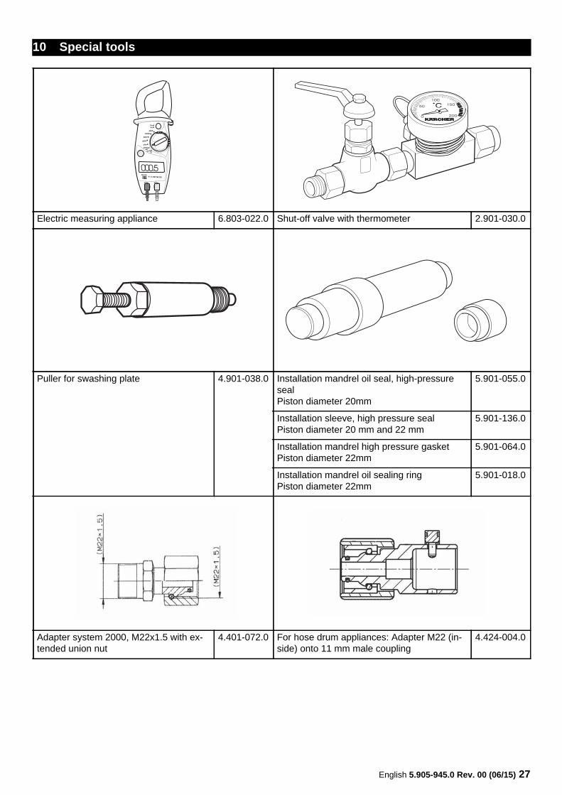
10 Special tools
Electric measuring appliance 6.803-022.0 Shut-off valve with thermometer 2.901-030.0
Puller for swashing plate 4.901-038.0 Installation mandrel oil seal, high-pressure sealPiston diameter 20mm
5.901-055.0
Installation sleeve, high pressure sealPiston diameter 20 mm and 22 mm
5.901-136.0
Installation mandrel high pressure gasketPiston diameter 22mm
5.901-064.0
Installation mandrel oil sealing ringPiston diameter 22mm
5.901-018.0
Adapter system 2000, M22x1.5 with ex-tended union nut
4.401-072.0 For hose drum appliances: Adapter M22 (in-side) onto 11 mm male coupling
4.424-004.0
28 English 5.905-945.0 Rev. 00 (06/15)
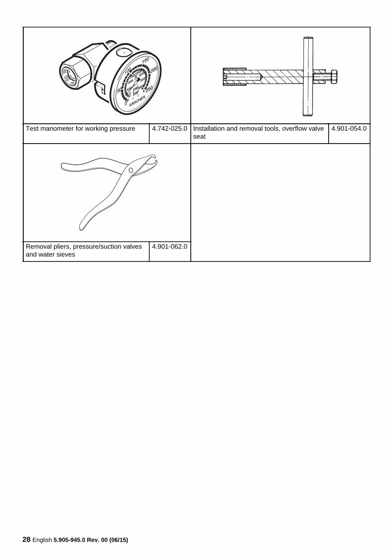
Test manometer for working pressure 4.742-025.0 Installation and removal tools, overflow valve seat
4.901-054.0
Removal pliers, pressure/suction valves and water sieves
4.901-062.0
English 5.905-945.0 Rev. 00 (06/15) 29
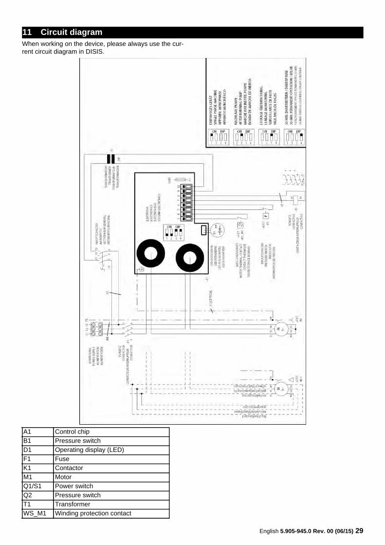
When working on the device, please always use the cur-rent circuit diagram in DISIS.
11 Circuit diagram
A1 Control chipB1 Pressure switchD1 Operating display (LED)F1 FuseK1 ContactorM1 MotorQ1/S1 Power switchQ2 Pressure switchT1 TransformerWS_M1 Winding protection contact
30 English 5.905-945.0 Rev. 00 (06/15)
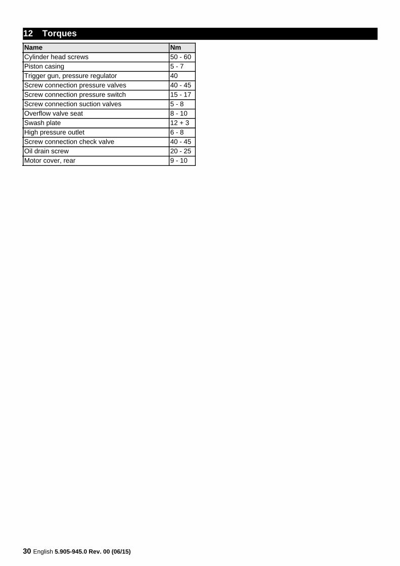
12 TorquesName NmCylinder head screws 50 - 60Piston casing 5 - 7Trigger gun, pressure regulator 40Screw connection pressure valves 40 - 45Screw connection pressure switch 15 - 17Screw connection suction valves 5 - 8Overflow valve seat 8 - 10Swash plate 12 + 3High pressure outlet 6 - 8Screw connection check valve 40 - 45Oil drain screw 20 - 25Motor cover, rear 9 - 10