harmony search algorithm based optimum detailed design...
TRANSCRIPT

Computers and Structures 147 (2015) 79–95
Contents lists available at ScienceDirect
Computers and Structures
journal homepage: www.elsevier .com/locate /compstruc
Harmony search algorithm based optimum detailed design of reinforcedconcrete plane frames subject to ACI 318-05 provisions
http://dx.doi.org/10.1016/j.compstruc.2014.10.0030045-7949/� 2014 Civil-Comp Ltd and Elsevier Ltd. All rights reserved.
⇑ Corresponding author. Tel.: +973 36089735.E-mail addresses: [email protected] (A. Akin), [email protected] (M.P. Saka).
Downloaded from http://www.elearnica.ir
A. Akin a, M.P. Saka b,⇑a Civil Structural Engineer, Thomas& Betts – Meyer Steel Structures, Memphis, TN, USAb University of Bahrain, Department of Civil Engineering, Isa Town, Bahrain
a r t i c l e i n f o
Article history:Received 29 September 2014Accepted 1 October 2014Available online 30 October 2014
Keywords:Cost optimizationStructural optimum designHarmony search algorithmReinforced concrete structuresHeuristics
a b s t r a c t
This paper presents the application of the harmony search based algorithm to the optimum detaileddesign of special seismic moment reinforced concrete (RC) frames under earthquake loads based onAmerican Standard specifications. The objective function is selected as the total cost of the frame whichincludes the cost of concrete, formwork and reinforcing steel for individual members of the frame. Themodular sizes of members, standard reinforcement bar diameters, spacing requirements of reinforcingbars, architectural requirements and other practical requirements in addition to relevant provisionsare considered to obtain directly constructible designs without any further modifications. For the RC col-umns, predetermined section database is constructed and arranged in order of resisting capacity. Theproduced optimum design satisfies the strength, ductility, serviceability and other constraints relatedto good design and stated in the relevant specifications. The lateral seismic forces are calculated accord-ing to ASCE 7-05 and it is updated in each iteration. Number of design examples is considered to dem-onstrate the efficiency of the optimum design algorithm proposed. It is concluded that the developedoptimum design model can be used in design offices for practical designs and this study is the firstapplication of the harmony search method to the optimization of RC frames and also the optimizationof special seismic moment RC frames to date.
� 2014 Civil-Comp Ltd and Elsevier Ltd. All rights reserved.
1. Introduction
In recent years structural optimization has witnessed an emer-gence of robust and innovative search techniques that strictlyavoid gradient-based search to counteract with challenges that tra-ditional optimization algorithms have faced for years. The basicconcept behind each of these techniques rests on simulating theparadigm of a biological, chemical, or social systems (such asevolution, immune system, and swarm intelligence or annealingprocess) that is automated by nature to achieve the task of optimi-zation of its own [1–3]. The design algorithms developed usingthese meta-heuristic search techniques are particularly suitablefor obtaining rapid and accurate solutions to problems in structuralengineering discipline [4,5]. This is particularly true in theoptimum design of steel structures where the design problemturns out to be a discrete optimization problem when it is formu-lated according to design codes used in practice.
In many practical engineering design problems, design variablesmay consist of continuous or discrete variables. In structural
optimization problems, the design variables are functions of thecross sections of the members and they are often chosen from alimited set of available values. For example, steel structural mem-bers are chosen from standard steel profiles in the market, struc-tural timber members are provided in certain sizes, andreinforced concrete members are usually designed and constructedwith discrete dimensional increments. Design optimization of rein-forced concrete (RC) structures is more challenging than that ofsteel structures because of the complexity associated with rein-forcement design. Also, only one material is considered for theoptimization problems of steel structures and the structural costis directly proportional to its weight in general. But in the case ofthe optimum design of concrete structures, three different costcomponents due to concrete, steel and formwork are to be consid-ered and the overall cost of the structure is affected from any slightvariation in the quantity of these components. Therefore, the opti-mization problem of concrete structures becomes the selection of acombination of appropriate values of design variables to make thetotal cost component the minimum.
In the literature, there are a number of studies on optimizationof RC members and frames. Practical applications of traditionaloptimization methods are not suitable for optimum design of RC

80 A. Akin, M.P. Saka / Computers and Structures 147 (2015) 79–95
frames and these algorithms require additional modifications to fitthe discrete nature of structural design variables. Choi and Kwak[6] haves suggested more practical discrete optimization tech-niques. They used direct search method to select appropriatedesign sections from some pre-determined discrete member sec-tions for the cost optimization of rectangular beams and columnsof RC frames based on the ACI and Korean codes. Balling and Yaoused the simulated annealing method which is one of themetaheuristic algorithm to optimize three-dimensional reinforcedconcrete frames [7]. Discrete variables as well as limits on thenumber of reinforcing bars and their topological arrangementsare considered in their study. Rajeev and Krishnamoorthy [8]applied a simple genetic algorithm to the cost optimization oftwo-dimensional RC frames. The detailing of reinforcement is con-sidered as a design variable in addition to cross-section dimen-sions. The allowable combinations of reinforcement bars forcolumns and beams were tabulated. Camp et al. [9] used geneticalgorithms (GAs) by constructing a database for beams and col-umns which contains the sectional dimensions and the reinforce-ment data in the practical range to optimize for optimum designof plane frames. Lee and Ahn [10] used to the genetic algorithmsto optimize reinforced concrete plane frames subject to gravityloads and lateral loads. In their study, the constructing data sets,which contain a finite number of sectional properties of beamsand columns in a practical range removed the difficulties in findingoptimum sections from a semi-infinite set of member sizes andreinforcement arrangements. Kwak and Kim [11] studied on opti-mum design of RC plane frames based on pre-determined sectiondatabase. In their study, pre-determined section databases of RCcolumns and beams are constructed and arranged in order ofresisting capacity and optimum solutions are obtained using directsearch method. They also used genetic algorithms for similar opti-mization problems [12]. Govindaraj and Ramasamy [13] usedgenetic algorithms for optimum detailed design for RC framesbased on Indian Standard specifications. The dimensions and rein-forcement arrangement of column, and the dimensions of beammembers alone are considered as a design variables and thedetailing of reinforcements in the beam members is carried outas a sub-level optimization problem. The modular sizes of mem-bers, available standard reinforcement bar diameters, spacingrequirements of reinforcing bars, architectural requirements onmember sizes and other practical requirements are arranged inorder to obtain for the optimum designs to be directly constructi-ble without any further modifications.
In the studies available in the literature the shear design calcu-lations of concrete members are not considered and the cost ofshear reinforcement (ties) is not taken into consideration in thetotal cost of the frame. Only the simple constraints such as capacityand regulations for flexural reinforcement are included. The detail-ing of the reinforcement bars is oversimplified and the develop-ment length of bars is not considered in the cost calculations. Insome of these studies, the lateral loading on the frame is consid-ered; however, the values of the lateral loads are taken as a con-stant even though the value of lateral loads change with theweight of the structure subject to seismic specifications. Akinand Saka [14] presented optimum design algorithm based on har-mony search method for the detailed design of special seismicmoment reinforced concrete plane frames considering provisionsof ACI 318-05 [15] and ASCE 7-05 [16]. The design algorithm pre-sented in this study considers all required code provisions andobtains the optimum solution by using harmony search algorithmfor reinforced concrete frames which is ready for practical designapplication.
In this study, the algorithm is extended to cover the optimumdesign of large size reinforced concrete frames. The paper isarranged as follows. In Section 2, the modeling of the detailed
optimum design problem is explained; the objective function, thedesign variables and the constraints derived from design provi-sions of ACI 318-05 are described. In Section 3, the harmony searchalgorithm is introduced and the optimum design process of rein-forced concrete frames based on the harmony search algorithm ispresented. In Section 4, illustrative examples are provided to dem-onstrate the efficiency and the performance of the algorithm pre-sented in this study. In Section 5, the summary and conclusionsare provided.
2. Modeling of optimum detailing design problem of reinforcedconcrete plane frames
In this study, harmony search method is used to obtain the opti-mum detailed design for reinforced concrete special seismicmoment frames. Reinforced concrete special moment frames areused as part of seismic force-resisting systems in buildings thatare designed to resist earthquakes. Beams, columns, and joints inmoment frames are proportioned and detailed to resist flexural,axial, and shearing actions during an earthquake. RC frames withspecial proportioning and detailing requirements are capable ofresisting strong earthquake shaking without significant loss ofstiffness or strength. These moment-resisting frames are called‘‘Special Moment Frames’’ because of these additional require-ments. A new optimum design algorithm is developed for the RCspecial seismic moment frames and the variable pool constructedto obtain buildable optimum designs. In the design formulation,the objective function is selected as the cost of the RC structurewhich includes the cost of concrete, reinforcement and formwork.To satisfy uniformity of the structure and to obtain constructibledesigns, the beam and column members are separated to designgroups. The design variables are categorized into two groups andarranged for the beam and column members. For the columns,the section database which includes the dimensions and the rein-forcement detailing of column sections is constructed with themost commonly used sections. The design constraints are imple-mented according to ACI 318-05. The constraints derived fromthe code are checked to obtain feasible designs. This study not onlyconsiders the flexural design constraints, but also the shear designconstraints and the seismic design constraints. The developmentlengths of the reinforcement steel bars are calculated accordingto the given regulations in the design specifications. The cost ofthe shear reinforcement and the impact of the development lengthon the cost are considered. In the design of frames, the matrix dis-placement method is used for the structural analysis and the loadcombinations are taken from the ACI code. The self-weight of RCbeams is included in the structural analysis and it is updated ineach iteration of the optimization process. The lateral seismicforces are calculated according to ASCE 7-05 and it is updated ineach iteration according to the selected design weight.
This paper is unique as it is the first application of the harmonysearch method to the design optimization of RC frames. Addition-ally, the detailing of the reinforcement in the concrete members,the consideration of the shear design of members, and the deriva-tion of the constraints are handled in more detail in this study. Thelateral seismic forces affecting the RC frame are obtained for thesite properties according to ASCE 7-05 even though other existingstudies do not consider the lateral seismic forces in their design.Also, this study is the sole study about the optimization of SpecialSeismic Moment RC Framesto date.
2.1. Objective function
In structural optimization problems, the objective function isgenerally described as the weight or total cost of structure. Usually,the weight of structure is used for the optimum design of steel

A. Akin, M.P. Saka / Computers and Structures 147 (2015) 79–95 81
structures. For the optimum design of reinforced concrete (RC)structures, the cost of structure is more convenient as an objectivefunction, because concrete structures involve different materialsand the nature of concrete design is different. In reality, the mini-mum weight design may not be the minimum cost design for espe-cially concrete structures. Besides the unit costs of differentmaterials involved concrete construction influence the total costof the concrete structures. For these reasons, the optimization prob-lem of concrete structures should be formulated in terms of thetotal cost, which includes the costs of concrete, steel and formwork.
In this study, the objective function is selected as the total costconsisting of individual cost components of concrete, steel andformwork. The cost of any component is inclusive of material, fab-rication, and labor. The objective function is expressedmathematically,
Minimize
f cost ¼ Cc þ Cs þ Cf ð1Þ
where Cc = the cost of concrete, Cs = the cost of reinforcing bars,Cf = the cost of formwork (includes labor and placement).
The costs of components, Cc, Cs, and Cf, are calculated for eachmember by the following equations. For the cost of concrete, Cc;
Cc ¼ Vc � ðUCcÞ ð2Þ
where Cc = the cost of concrete, Vc = the total volume of concrete,(UCc) = the unit cost of concrete ($/m3).
Vc ¼XNcol
i¼1
bidiLcolumn;i þXNbeam
j¼1
bw;jhjLclear beam;j ð3Þ
where Ncol = the number of column members, bi and di = the widthand depth of ith column member with rectangular cross section,Lcolumn,i = the length of ith column member, Nbeam = the number ofbeam members, bw,j = the width of jth beam, hj = the height of jthbeam, Lclear beam,j = the clear span length of jth beam.
For the cost of steel, Cs;
Cs ¼Ws � ðUCsÞ ð4Þ
where Cs = the cost of steel, Ws = the total weight of steel used asreinforcement bar in the concrete frame, (UCs) = the unit cost ofsteel ($/kg).
Ws ¼XNcol
i¼1
XNbar;i
j¼1
As;jlbar;j þXNcol
i¼1
XNtie;i
k¼1
Ash;kltie;k þXNbeam
m¼1
XNbar;m
l¼1
As;llbar;l
þXNbeam
m¼1
XNtie;m
n¼1
Ast;nltie;n ð5Þ
where Nbar,. . . = the number of longitudinal reinforcement barsplaced in the member, Ntie,. . . = the number of ties used in the mem-ber, As,. . . = the area of reinforcement bars, lbar,. . . = the length of rein-forcement bars, Ast,. . .,Ash,. . . = the area of shear reinforcement bars(ties) ltie,. . . = the length of ties.
For the cost of formwork, Cf;
Cf ¼ Af � ðUCf Þ ð6Þ
where Cf = the cost of formwork, Af = the total formwork area,(UCf) = the unit cost of formwork ($/m2).
Af ¼XNcol
i¼1
f2ðbi þ diÞLcolumn;i � ðAreabeams@joint;iÞg
þXNbeam
j¼1
fðbw;j þ 2hjÞLclear beam;jg ð7Þ
where Areabeams@joint,i = the cross-section area of beams connectedto the ith column at joint.
The detailed evaluation of objective function is defined by Eqs.(2–7). The unit costs are based on market prices and their valueschanges from time to time and also from country to country. Forthese reasons, the unit price data cannot be fixed and needs tobe updated. In the previous studies in the literature, researchersused different country design specifications for design and differ-ent market prices for unit costs depending to their countries. Thedifferent unit material costs are used for the design examples,and these values are given with concerned examples.
2.2. Design variables
Design variables are divided two groups as column design vari-ables and beam design variables and to obtain practical designsbeams and columns are separated to groups. Total number ofdesign variables is determined according to number of columnand beam groups.
2.2.1. Beam design variablesFor beam design groups, the cross-section of beams, the area of
reinforcement bars along all beams, and the area of reinforcementbars placed on the top and bottom of beam spans and supports areconsidered as design variables. The cross-sectional dimensions ofthe beam are considered as the design variable. In addition tocross-section dimension of the beam, the areas of longitudinal barsthat are placed continuously at the bottom of all the beams and thetensile reinforcements at the spans of beams, and supports for eachbeam are also considered as the design variable. These design vari-ables and their numbers in the problem are defined in Table 1. Thedesign variables relevant with reinforcement bars are not definedas the surface area of reinforcing bars. Instead the reinforcementbar layout is defined and these design variables relevant with rein-forcement are expressed in terms of the number of reinforcing barsand the diameter of reinforcing bars. By this way, design processcan reach directly constructible optimum designs. The details ofthe design variables are shown in Fig. 1. The total number of thebeam design variables, Nbdv, for one beam group changes accordingto number of span (bay) in frame. Total number of beam designvariables for one beam group is calculated by Eq. (8);
Nbdv ¼ 5þ 4nbay ð8Þ
The total number of beam design variables when each beamgroup considered, Ndvbeam, is computed by following equation;
Ndvbeam ¼ nbeamgroup � Nbdv ð9Þ
where Nbdv = the total number of the beam design variables for onebeam group, nbay = the number of bays in a frame, nbeam group = thetotal number of beam group.
For the cross-sectional and reinforcement design variables, thedesign variable pools are created as shown in Table 2. For the rein-forcement design variables, the values are selected such that theygive constructable reinforcement areas. In other words, the num-ber and diameter of the bar for a beam can be considered as onedesign variable (n/d n; number of bars, d; diameter of bars). For thispurpose, the variable pool table is composed of a combination ofnumber and diameter of bars. For the reinforcement design vari-ables, the design variable pool is created by the combination ofnumber and diameter of reinforcement bars as shown in Table 2.It is apparent from the design pool that 61 different combinationof number and diameter of a bar can be arranged for each rein-forcement design variables. The 6 reinforcement bar combinationare used for the reinforcement continues through the top (Xi,2)and bottom (Xi,3) of all the beams. In this optimum design problem,material strengths, unit costs of materials, structural geometry,support conditions, loading conditions, and cover details are pre-assigned as design parameters at the beginning of the optimization

Table 1Cross-sectional and reinforcement design variables for beam groups.
Design variables Number
Xi,1 The width and the height of beam cross-section 1Xi,2 The area of the steel reinforcement that continues through the top of all the beamsa 1Xi,3 The area of the steel reinforcement that continues through the bottom of all the beamsa 1Xi,4 � Xi,k The area of the top steel reinforcement at spans of beamsa nbay
Xi,k+1 � Xi,m The area of the bottom steel reinforcement at spans of beamsa nbay
Xi,m+1 � Xi,n The area of the top steel reinforcement at the supportsa nbay+1Xi,n+1 � Xi,Nbdv The area of the bottom steel reinforcement at supportsa nbay+1
i = number of beam group (ith beam group), nbay; number of spans (k = 3 + nbay, m = 3 + 2nbay, n = 4 + 3nbay, Nbdv = 5 + 4nbay).a For the reinforcement design variables, the areas of steel reinforcement bars are defined in terms of the number and diameter of the bars (n/d n; number of bars, d;
diameter of bars) to obtain constructible reinforcement areas.
Fig. 1. The reinforcement bar layout and the design variables for ith beam group.
82 A. Akin, M.P. Saka / Computers and Structures 147 (2015) 79–95
process. However, the value of the dead load which includes theself-weight of beam depending on the cross-sectional dimensionsis automatically updated during the design cycles.
2.2.2. Column design variablesThe optimum design problem of RC buildings is more complex
than the optimal design of steel structures because only one struc-tural material is considered in steel structures and the cost of thesteel structures is only assumed to be proportional to its weight.Unlike the design of steel structures, there is infinite set of membersize and amount of steel reinforcement used in the design of rein-forced concrete (RC) buildings. The importance difference betweenoptimum designs of steel and concrete structures is that morecombinatorial characteristics affect the determining the cross-sec-tional dimensions, and the layout and arrangements of reinforcingbars in RC building design. In addition to the discrete and combina-torial nature of the RC sections, the restrictions and reinforcementdetailing specified in the design specifications make the optimumdesign of RC buildings even more complicated.
In the literature, many researchers suggested and used a lot ofpractical discrete optimization techniques developed for discreteoptimum design of RC frames by the construction of a concretesection database [6–10]. In these studies, discrete optimum sec-tions are directly searched based on the relationship between thesection identification numbers and properties (dimensions andresistant capacities) of sections. The sections widely used in prac-tical design are selected to construct database.
In this study, the concrete section database is constructed forthe selection of section of column members. Practically, the dimen-sions of column sections in a RC frames are usually increased by50 mm a step, and the diameters of reinforcing bars in columnmembers change between 14 and 30 mm most frequently. Thedesign variables for the construction of column section databaseare selected as the dimensions of columns in x and y directions,the diameter of reinforcement bars at the cross-section of columnand numbers of reinforcement bars in both sides of the column asshown in Fig. 2. The lower–upper bounds and increments of thesevariables are given in Table 3. Assigning these values to variables

Table 2Variable poll for beam design variables.
# X1 (mm) # X2 � X3 # X4 � XNbdv
1 250/400 1 2/12 1 NNR2 250/450 2 2/14 2 1/123 250/500 3 3/12 3 1/144 250/550 4 2/16 4 1/165 250/600 5 3/14 5 1/186 300/400 6 3/16 6 1/207 300/450 7 1/228 300/500 8 1/249 300/550 9 1/26
10 300/600 10 1/2811 300/650 11 1/3012 300/700 12 2/1213 350/500 13 2/1414 350/550 14 2/1615 350/600 15 2/1816 350/650 16 2/2017 350/700 17 2/2218 400/600 � �19 400/650 � �20 400/700 45 5/1821 400/750 46 5/2022 400/800 47 5/2223 450/700 48 5/2424 450/750 49 5/2625 450/80026 450/85027 450/900 55 6/1828 500/700 56 6/2029 500/750 57 6/2230 500/800 58 6/2431 500/850 59 6/2632 500/900 60 6/28
61 6/30
a NNR; no need reinforcement.
A. Akin, M.P. Saka / Computers and Structures 147 (2015) 79–95 83
all possible section combinations are composed, and the combina-tions satisfy the constraints between 12 and 20 (given inSection 2.3.1) are taken the section pool. However, the number of
Fig. 2. The design variables for constru
possible combinations is 37,440 and obtained feasible sectionsnumber is obtained as 6199. This quantity of feasible column sec-tions is too large to obtain the optimum results using optimizationmethods. Additionally, some of sections have similar section prop-erties and flexural moment strength. For these reasons, obtainedfeasible column sections are evaluated to their section propertiesand flexural strength for balanced case. Finally, the feasible solu-tion number in the column section database is decreased to 219which is a reasonable number for optimum design process. Theselected feasible column sections are given in Table 4. The com-pressive strength of concrete and the yield strength of steel aretaken as 30 MPa and 400 MPa, respectively, and the cover of theconcrete section is taken as 50 mm to evaluate the strength of sec-tions and to select the sections in the database. In the optimumdesign process, the interaction diagrams for the assigned sectionsare computed for the given material strength properties and thedetailing of the section.
2.3. Constraints
Constraints to be considered in the optimum design problemare strength, serviceability, ductility and other side constraints.Constraints can be imposed separately for column groups, beamgroups and connection regions. These constraints are taken fromACI 318-05.
2.3.1. Constraints for column groupsTwo types of design constraints are considered for the column
members of the RC frame. The first type includes those constraintson the axial load and moment resistance capacities of the section,clear spacing limits between reinforcing bars, and the minimumand the maximum percentage of steel allowed. The second typeconsists of those constraints defining architectural requirementsand good design and detailing practices. These include therequirement of the minimum and the maximum dimensions ofcolumn, the maximum aspect ratio of the section, maximum
ction of column section database.

Table 4Design variables database for column sections.
# d b / n1 n2 Pn,max (kN) Pb (kN) Mb (kN m)
1 400 300 14 1 1 2288.78 851 130.972 400 300 14 1 2 2363.72 848.46 142.133 400 350 14 2 1 2695.22 991.85 149.34 400 350 14 1 2 2695.22 991 158.385 400 350 22 1 1 3060.77 972.18 193.676 400 400 16 2 1 3141.44 1128.26 175.977 400 400 18 1 1 3147.55 1125.48 184.34� � � � � � �� � � � � � �31 550 300 20 4 1 3805.51 1248.66 316.5432 550 300 20 2 2 3652.57 1222.19 330.1933 550 350 14 5 2 3865.19 1456.02 305.2834 550 350 14 3 3 3790.25 1441.67 311.3335 550 350 20 2 1 3955.43 1431.02 326.84� � � � � � �� � � � � � �59 600 400 22 3 2 5273.47 1818.46 504.3560 600 400 18 4 4 5216.88 1816.61 508.4561 600 450 16 3 2 5160.46 2043.57 444.72� � � � � � �� � � � � � �79 650 500 20 5 3 6916.36 2505.33 696.3380 650 500 20 3 6 7069.31 2459.97 795.5881 650 500 24 3 5 7589.33 2459.47 889.6182 700 300 14 5 1 4080.31 1641.18 399.3783 700 300 20 4 2 4704.34 1640.9 527.0184 700 300 20 5 2 4857.29 1662.59 543.7� � � � � � �� � � � � � �111 750 300 16 4 1 4414.58 1762.82 472.77112 750 300 14 5 2 4403.88 1766.52 477.93113 750 300 16 5 1 4512.47 1778 484.58114 750 300 18 5 1 4720.48 1788.23 520.22� � � � � � �� � � � � � �141 800 350 20 4 2 5864.59 2208.09 725.95142 800 350 20 5 2 6017.54 2232.38 745.8143 800 350 18 7 3 6127.66 2246.81 767.84144 800 350 20 7 2 6323.43 2268.88 783.91� � � � � � �� � � � � � �158 800 500 24 5 5 9272.95 3154.95 1299.31159 850 350 14 7 1 5680.51 2371.26 664.1160 850 350 16 7 1 5909.93 2386.99 707161 850 350 14 7 3 5830.4 2366.19 721.87162 850 350 16 6 2 5909.93 2369.95 731.11� � � � � � �� � � � � � �187 900 450 20 5 3 8242.36 3226.06 1141.62188 900 500 20 5 5 9294.13 3564.72 1350.11189 950 400 20 5 1 7522.09 3057.72 1027.23� � � � � � �� � � � � � �216 1000 500 20 5 3 9816.98 3998.45 1473.01217 1000 500 18 5 5 9774.16 3977.65 1504.87218 1000 500 22 6 4 10508.3 4025.99 1677.74219 1000 500 28 5 2 10985.5 4071.49 1749.45
Table 3Design variable bounds for RC column design examples.
Design variables Lower bound Upper bound Increment (step size) Number of possible values in the range
X1c b (mm) 300 500 50 mm 5X2c d (mm) 400 1000 50 mm 13X3c / (mm) {14,16,18,20,22,24,26,28,30} 9X4c and X5c n1 and n2 0 7 1 8
84 A. Akin, M.P. Saka / Computers and Structures 147 (2015) 79–95
number of reinforcing bars and other reinforcement requirements.The constraints are explained and expressed in a normalized formas given below.
Two types of design constraints are considered for the columnmembers of the RC frame. The first type includes those constraints
on the axial load and moment resistance capacities of the section,clear spacing limits between reinforcing bars, and the minimumand the maximum percentage of steel allowed. The second typeconsists of those constraints defining architectural requirementsand good design and detailing practices. These include the require-ment of the minimum and the maximum dimensions of column, themaximum aspect ratio of the section, maximum number of reinforc-ing bars and other reinforcement requirements. The constraints areexplained and expressed in a normalized form as given below.
The maximum axial load capacity of columns, Pn,max should begreater than the factored axial design load acting on the columnsection, Pd;
g1ðxÞ ¼Pdði;jÞ
Pn;maxði; jÞ� 1 6 0 i ¼ 1;Ncol j ¼ 1;6 ð10Þ
where i = number of the column (ith column), Ncol = total number ofcolumns, j = load combination type.
For a column section with uni-axial bending, the moment carry-ing capacity of column section, Mn, obtained for each factored axialdesign load, Pd, should be greater than the applied factored designmoment, Md;
g2ðxÞ ¼Mdði;jÞ
Mn@Puði;jÞ
� 1 6 0 i ¼ 1;Ncol j ¼ 1;6 ð11Þ
where i = number of the column (ith column), Ncol = total number ofcolumns, j = load combination type.
The percentage of longitudinal reinforcement steel, q, in a col-umn section should be between minimum and maximum limitspermitted by design specification (qmin = 0.01 and qmax = 0.06);
g3ðxÞ ¼qmin
qi� 1 6 0 ð12Þ
and
g4ðxÞ ¼qi
qmax� 1 6 0 i ¼ 1;Ncol ð13Þ
where i = number of the column (ith column), Ncol = total number ofcolumns.
The width b and the height d of a column section should not beless than the minimum dimensions limit value given for columns(min. dimension, cdmin = 300 mm);
g5ðxÞ ¼cdmin
bi� 1 6 0 ð14Þ
and
g6ðxÞ ¼cdmin
di� 1 6 0 i ¼ 1;Ncol ð15Þ
where i = number of the column (ith column), Ncol = total number ofcolumns.
The ratio of shorter dimension of column section to longer oneshould be greater than permitted limit (cdrmin = 0.40);
g7ðxÞ ¼cdrmin
ðbi=diÞ� 1 6 0 i ¼ 1;Ncol ð16Þ
where i = number of the column (ith column), Ncol = total number ofcolumns.
A. Akin, M.P. Saka / Computers and Structures 147 (2015) 79–95 85
The minimum diameter of longitudinal reinforcing bars, /, in acolumn section should be greater than minimum bar diameter,/min, specified by design code;
g8ðxÞ ¼/min
/i� 1 6 0 i ¼ 1;Ncol ð17Þ
where i = number of the column (ith column), Ncol = total number ofcolumns.
The total number of longitudinal reinforcing bars, nrb, in a col-umn section should be smaller than specified maximum number ofreinforcing bars, nrbmax, for detailing practice (nrbmax = 24);
g9ðxÞ ¼nrbi
nrbmax� 1 6 0 i ¼ 1;Ncol ð18Þ
where i = number of the column (ith column), Ncol = total number ofcolumns.
The minimum and maximum clear spacings between longitudi-nal bars, a, in a column section should be between minimum andmaximum limits, amin and amax, specified for detailing practice(amin = 50 mm and amax = 150 mm);
g10ðxÞ ¼amin
ai� 1 6 0 ð19Þ
and
g11ðxÞ ¼ai
amax� 1 6 0 i ¼ 1;Ncol ð20Þ
where i = number of the column (ith column), Ncol = total number ofcolumns.
The shear force capacity of column section, /Vn, should begreater than applied factored design shear force, Vd;
g12ðxÞ ¼Vdði;jÞ
/Vnði;jÞ� 1 6 0 i ¼ 1;Ncol j ¼ 1;6 ð21Þ
where i = number of the column (ith column), Ncol = total number ofcolumns, j = load combination type.
Also, the shear force capacity of column section, /Vn, should begreater than the minimum capacity shear forces, min{Vc
e;Vbe },
based on probable maximum flexural strength of column, Vce ,
and based on probable maximum flexural strengths at the endsof beams framed into the top joint of column, Vb
e;
g13ðxÞ ¼min Vc
eðkÞ VbeðkÞ
n o/VnðkÞ
� 1 6 0 k ¼ 1;Ncolumn groupð22Þ
where k = number of the column group (kth column group),Ncol = total number of column groups.
The factored design shear force acting on column section,Vd,should be less than allowed maximum shear force capacity,/Vmax;
g14ðxÞ ¼Vdði;jÞ
/Vmax ði;jÞ� 1 6 0 i ¼ 1;Ncol j ¼ 1;6 ð23Þ
where i = number of the column (ith column), Ncol = total number ofcolumns, j = load combination type.
The area of shear reinforcement (ties), Ash, should be greaterthan limitations on the minimum area of shear reinforcement,Ash,min;
g15ðxÞ ¼Ash;min
Ashði;jÞ� 1 6 0 k ¼ 1;Ncolumn 2group j ¼ 1;3 ð24Þ
Ash;min !max
0:062ffiffiffiffif c
pbd s
f yP 0:35d s
f y
0:3sbcAg
Ach� 1
� �f 0cf y
0:09sbcf cf y
8>>><>>>:
ð25Þ
where k = number of the column group (kth column group),Ncolumn group = total number of column groups, j = three (top, middleand bottom parts) shear design region of column, fc = the compres-sive strength of concrete, fy = the yielding strength of reinforcingsteel, b andd = the width and height of column section, s = thespacing between stirrups (ties), bc = the cross-sectional dimensionof column core measured center-to-center of outer legs of thetransverse reinforcement comprising area Ash, Ag = the gross areaof section, Ach = the cross-sectional area of member measuredout-to-out of transverse reinforcement.
The spacing between stirrups, s, in the column should be greaterthan minimum spacing, smin (smin = 50 mm) for constructionalrequirements;
g16ðxÞ ¼smin
sði;jÞ� 1 6 0 k ¼ 1;Ncolumn group j ¼ 1;3 ð26Þ
where k = number of the column group (kth column group),Ncolumn group = total number of column groups, j = three (top, middleand bottom parts) shear design region of the column.
At the top and bottom ends of column members, the spacingbetween stirrups, s, should be less than maximum spacing of shearreinforcement for end regions of column, smax,end;
g17ðxÞ ¼sði;jÞ
smax;end� 1 6 0 k ¼ 1;Ncolumn group j ¼ 1;2 ð27Þ
smax;end !min
d4b4
6/b
8><>: ð28Þ
where k = number of the column group (kth column group),Ncolumn group = total number of column groups, j = two (top and mid-dle parts) shear design region of the column, b andd = the width andheight of column section, s = the spacing between stirrups (ties),/b = the diameter of longitudinal reinforcing bars.
For the middle parts column members, the spacing betweenstirrups, s, should be less than maximum spacing of shearreinforcement, smax,middle;
g18ðxÞ ¼sði;middleÞ
smax;middle� 1 6 0 k ¼ 1;Ncolumn group ð29Þ
smax;middle !min6/b
15 cm
�ð30Þ
where k = number of the column group (kth column group),Ncolumn group = total number of column groups, /b = the diameter oflongitudinal reinforcing bars.
The length of top and bottom shear regions, lo, should be greaterthan allowable design length, lo,min;
g19ðxÞ ¼l0;min
l0ði;jÞ� 1 6 0 k ¼ 1;Ncolumn group j ¼ 1;2 ð31Þ
l0;min !maxlarger of b and d
1=6 clear span of column
45 cm
8><>: ð32Þ
where k = number of the column group (kth column group),Ncolumn group = total number of column groups, j = two (top andmiddle parts) shear design region of column, b andd = the widthand height of column section.
2.3.2. Constraints for beam groupsConstraints to be imposed for each beam group are based on
strength, serviceability, ductility and other side constraints. The

86 A. Akin, M.P. Saka / Computers and Structures 147 (2015) 79–95
normalized forms of all constraints considered in optimum designproblem are given below.
For three critical sections (left end, middle part and right end) ofeach beam, the negative (with top steel in tension) and positive(with bottom steel in tension) moment carrying capacities of sec-tion for Mn, should be greater than the applied factored designmoments Md;
g20ðxÞ ¼Mdði;j;k;lÞ
Mnði;j;k;lÞ� 1 6 0 i ¼ 1;Nbeam j ¼ 1; . . . ;6k ¼ 1;3l ¼ 1;2
ð33Þ
where i = number of the beam (ith beam), Nbeam = total number ofbeams, j = load combination type, k = three critical sections for flex-ural design of beam, l = the negative moment and positive momentsituations (top steel in tension or bottom steel in tension).
The tension area of longitudinal reinforcement steel bars intension As, for three critical sections in a beam should satisfy the
START
Generation of Harmony Memory Generation of initial harmony memory with feasible designvectors (randomly selected, satisfies constraints, and sorted by the cost of frame)
Initialize Problem Specification of each design variableand design groups for beam and column members
Specification of the constraintsminimize or maximize f(xi )subject to constraints
I
Step 1
Step 2
N O
Termination criterionMaximum number of searches
satisfied?
YES
N OStep 5
STOP
Fig. 3. Optimum design procedure of RC fr
minimum and the maximum requirements permitted by designspecification;
g21ðxÞ ¼As;min ði;k;lÞ
Asði;k;lÞ� 1 6 0 i ¼ 1;Nbeam k ¼ 1;3 l ¼ 1;2
ð34Þ
and
g22ðxÞ ¼Asði;k;lÞ
As;max ði;k;lÞ� 1 6 0 i ¼ 1;Nbeam k ¼ 1;3 l ¼ 1;2
ð35Þ
As;min !max0:25 f 0c
f ybwh
1:4 bwhf y
8<:
As;max ¼ 0:025bwh ðfor the total area
of top and bottom flexural barsÞ
ð36Þ
nitialize HS parametersSpecification of harmony memory size (HMS), harmony memory considering rate (HMCR), pitch adjusting rate (PAR) , and termination criterion (maximum number of search)
Improvision of new harmony Generate new design (vector) according to three rules;- HMCR (memory considering)- PAR (pitch adjusting)- Random selection
Step 3
Evaluation of new harmony Does A new design vector satisfy
the constraints ?and
Is the cost of new design better than the worst design cost in HM?
Step 4
YES
Update harmony - eliminate the design vector have the
worst cost in HM - insert a new feasible design vector
into HM- sorted design vectors in HM by the
cost of design vectors (f(x)) goto step 5
ames with Harmony search algorithm.
A. Akin, M.P. Saka / Computers and Structures 147 (2015) 79–95 87
where i = number of the beam (ith beam), Nbeam = total number ofbeams, k = three critical sections for flexural design of beam,l = the negative moment and positive moment situations (checkingfor top and bottom reinforcement steel area), bw andh = the widthand height of beam section, fc = the compressive strength ofconcrete,fy = the yielding strength of reinforcing steel.
At any end (support) of the beams, the positive momentcapacity M�
n , (i.e., associated with the bottom steel) should begreater than 1/2 of the beam negative moment capacity Mþ
n , (i.e.,associated with the top steel) at that end;
g23ðxÞ ¼12 M�
n;ði;kÞ
Mþn;ði;kÞ
� 1 6 0 i ¼ 1;Nbeam k ¼ 1;2 ð37Þ
where i = number of the beam (i.th beam), Nbeam = total number ofbeams, k = the left and right ends of beam.
g = 30 kN/m
g = 30 kN/m
g = 30 kN/m
g = 30 kN/m
g = 30 kN/m
Beam group 1
Beam group 2
Beam group 2
Beam group 2
Beam group 2
Col
umn
gr. 1
Col
umn
gr. 2
Col
umn
gr. 1
Col
umn
gr. 2
Col
umn
gr. 1
Col
umn
gr. 2
Col
umn
gr. 1
Col
umn
gr. 2
Col
umn
gr. 1
Col
umn
gr. 2
6,00
g = 30 kN/m
Beam group 2
Col
umn
gr. 1
Col
umn
gr. 2
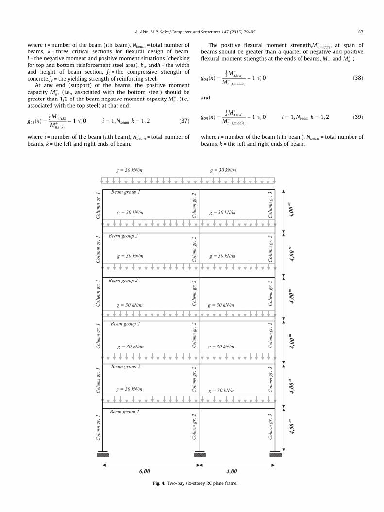
Fig. 4. Two-bay six-stor
The positive flexural moment strength,Mþn;middle, at span of
beams should be greater than a quarter of negative and positiveflexural moment strengths at the ends of beams, M�
n; and Mþn ;
g24ðxÞ ¼14 M�
n;ði;kÞ
Mþn;ði;middleÞ
� 1 6 0 ð38Þ
and
g25ðxÞ ¼14 Mþ
n;ði;kÞ
Mþn;ði;middleÞ
� 1 6 0 i ¼ 1;Nbeam k ¼ 1;2 ð39Þ
where i = number of the beam (i.th beam), Nbeam = total number ofbeams, k = the left and right ends of beam.
g = 30 kN/m
g = 30 kN/m
g = 30 kN/m
g = 30 kN/m
g = 30 kN/m
Col
umn
gr. 3
Col
umn
gr. 3
Col
umn
gr. 3
Col
umn
gr. 3
Col
umn
gr. 3
4,00
m4,
00m
4,00
m4 ,
00m
4,00
m
4,00
g = 30 kN/m
Col
umn
gr. 3
4,00
m
ey RC plane frame.

88 A. Akin, M.P. Saka / Computers and Structures 147 (2015) 79–95
The shear force capacity of three regions (left and right ends,and span) of beam, /Vn, should be greater than applied factoreddesign shear force, Vd;
g26ðxÞ ¼Vdði;j;kÞ
/Vnði;j;kÞ� 1 6 0 i ¼ 1;Nbeam j ¼ 1;6 k ¼ 1;3 ð40Þ
where i = number of the beam (i.th beam), Nbeam = total number ofbeams, j = load combination type, k = three critical region (left andright ends, and span) for shear design of beam.
Also, the shear force capacity of design regions in a beam, /Vn,should be greater than the probable shear forces based on probablemaximum flexural strengths with the factored gravity loads atbeam ends of beam, max{Ve1,Ve2};
g27ðxÞ ¼max Ve1ðiÞ Ve1ðiÞ
� �/Vnði;kÞ
� 1 6 0 i ¼ 1;Nbeam k ¼ 1;3
ð41Þ
where i = number of the beam (i.th beam), Nbeam = total number ofbeams, k = three critical region (left and right ends, and span) forshear design of beam.
The factored design shear forces at the middle and ends ofbeam,Vd, should be less than allowed maximum shear force capac-ity, /Vmax;
g28ðxÞ ¼Vdði;kÞ
/Vmax ði;kÞ� 1 6 0 i ¼ 1;Nbeam k ¼ 1;3 ð42Þ
where i = number of the beam (i.th beam), Nbeam = total number ofbeams, k = three critical region (left and right ends, and span) forshear design of beam.
The spacing between stirrups s, in the middle and the ends ofthe beam should be greater than the minimum spacing, smin
(smin = 50 mm) for constructional requirements;
g29ðxÞ ¼smin
sði;kÞ� 1 6 0 k ¼ 1;Nbeam j ¼ 1;3 ð43Þ
where i = number of the beam (i.th beam), Nbeam = total number ofbeams, k = three critical region (left and right ends, and span) forshear design of beam.
At the left and right ends of beam members, the spacingbetween stirrups, s, should be less than maximum spacing limitof shear reinforcement for end regions of beam smax,end;
g30ðxÞ ¼sði;jÞ
smax;end� 1 6 0 i ¼ 1;Nbeam k ¼ 1;2 ð44Þ
smax;end !min
h4
30 cm24/b
8><>: ð45Þ
where i = number of the beam (ith beam), Nbeam = total number ofbeams, k = three critical regions (left and right ends and the span)for shear design of beam, h = the height of beam section, /b = thediameter of shear reinforcing bars (ties).
Along the span of a beam member, the spacing between stirrupss should be less than maximum spacing of the shear reinforcement,smax,middle;
g31ðxÞ ¼sði;middleÞ
smax;middle� 1 6 0 i ¼ 1;Nbeam ð46Þ
smax;middle !min
h2
60 cm30 Asv
f ybw
8><>: ð47Þ
where i = number of the beam (ith beam), Nbeam = total number ofbeams, h = the height of beam section, bw and h = the width and
height of column section, Asv= the area of shear reinforcement(tie), fy = the yielding strength of reinforcing steel.
The area of shear reinforcement (ties) in beam sections (spanand ends of beam), Asv, should be greater than limitations on theminimum area of shear reinforcement, Asv,min;
g32ðxÞ ¼Asv;min
Asvði;kÞ� 1 6 0 i ¼ 1;Nbeam k ¼ 1;3 ð48Þ
Asv;min ¼ 0:062ffiffiffiffif c
qbwh
sf y
P 0:35hsf y
ð49Þ
where i = number of the beam (ith beam), Nbeam = total number ofbeams, k = three critical regions (left and right ends, and along thespan) for shear design of a beam, fc = the compressive strength ofconcrete,fy = the yielding strength of reinforcing steel, bw andh = the width and height of beam section, s = the spacing betweenstirrups (ties).
The width of beams, bw, should be greater than allowable min-imum width for beams, bw,min;
g33ðxÞ ¼bw;min
bwðiÞ� 1 6 0 i ¼ 1;Nbeam ð50Þ
bw;min !max25 cmLbeamðiÞ
50
(ð51Þ
where i = number of the beam (ith beam), Nbeam = total number ofbeams, Lbeam = the length of beam.
The height of beams, h, should be greater than allowable mini-mum height for beams, h,min;
g34ðxÞ ¼hmin
hðiÞ� 1 6 0 i ¼ 1;Nbeam ð52Þ
hmin !LbeamðiÞ
18:5 for one end continuousLbeamðiÞ
21 for both end continuous
(ð53Þ
where i = number of the beam (ith beam), Nbeam = total number ofbeams, Lbeam = length of the beam.
2.3.3. Constraints for jointsAt frame joints, the width of beams, bw, should be smaller than
the width of column, b, framed into the ends joint of beam;
g35ðxÞ ¼bwðiÞ
bðiÞ� 1 6 0 i ¼ 1;Njoint ð54Þ
where i = number of the joint (ith joint), Njoint = total number ofjoints.
The width of the top column, b, should be equal or smaller thanthe width of the bottom column at the column joints;
g36ðxÞ ¼btop columnðiÞ
bbottom columnðiÞ� 1 6 0 i ¼ 1;Njoint ð55Þ
where i = number of the joint (ith joint), Njoint = total number ofjoints.
The height of the top column, h, should be equal or smaller thanthe width of the bottom column at the column joints;
g37ðxÞ ¼htop columnðiÞ
hbottom columnðiÞ� 1 6 0 i ¼ 1;Njoint ð56Þ
where i = number of the joint (ith joint), Njoint = total number ofjoints.
The sum of nominal flexural strengths of columns framing intothe joint, RMnc, should be 1.2 times greater than the sum of nom-inal flexural strengths of beams framing into same joint, RMnb,
g38ðxÞ ¼65 RMnbðiÞ
RMncðiÞ� 1 6 0 i ¼ 1;Njoint ð57Þ

A. Akin, M.P. Saka / Computers and Structures 147 (2015) 79–95 89
where i = number of the joint (ith joint), Njoint = total number ofjoints.
The relative story displacements, Di, should be smaller than theallowable story drift, Da, given in the design specification;
g39ðxÞ ¼Dihi
� �Da� 1 6 0 i ¼ 1;Nstory ð58Þ
where i = number of the story (ith story), Nstory = total number ofstories, hi = the height of story from base level.
Table 5Input data for two-bay six-story RC frame example.
Input datas for two-bay six-storey frame
Compressive strength of concrete, fc (N/mm2) 20Yielding stress of steel, fy (N/mm2) 415Cover for beams, mm 25Cover for columns, mm 25Total number of beam groups 2Total number of beams 12Total number of column groups 3Total number of columns 18Lateral force for each story (kN) 10Factored uniformly distributed load on beams (kN/m) 30
Harmony Search Algorithm ParametersHMS 45HMCR 0.80PAR 0.15Max. iteration 100,000
Table 6The optimum values of design variables for two-bay six-story RC frame.
Optimum design results for two-bay six-storey frame
Design variables Column Column ColumnGr. 1 Gr. 2 Gr. 3
Optimum column design resultsSection number in design pool (3) (82) (3)The height of section, h (mm) 400 500 400The height of section, b (mm) 350 300 350The diameter of reinforcement bars, /(mm) 14 14 14The number of bars in x direction, n1 2 3 2The number of bars in y direction, n2 1 2 1Total reinforcement 10/14 14/14 10/14
Design variables Beam Gr. 1 Beam Gr. 2
Optimum beam design resultsx1 25/40 (1) 25/40 (1)x2 2/12 (1) 2/12 (1)x3 2/12 (1) 2/12 (1)x4 1/16 (4) 1/16 (4)x5 1/16 (4) 1/14 (3)x6 1/12 (2) 1/12 (2)x7 1/12 (2) 1/12 (2)x8 1/14 (3) 2/14 (7)x9 NNR⁄ (1) NNR⁄ (1)x10 1/14 (3) 1/16 (4)x NNR⁄ (1) NNR⁄ (1)
3. Harmony search method
The harmony search (HS) algorithm is used to determine theoptimum solution of the design optimization problem describedin the previous section. This algorithm is one of the recent meta-heuristic optimization techniques which is originated by Geemet al. [17–19] The harmony search algorithm only needs adjust-ment of a few parameters, consists of simple steps and has a fastconvergence rate [20–28]. The algorithm is widely used to obtainthe solution of optimum structural design problems [29–33].
The HS algorithm mimics the improvisation of music players forsearching the better harmony. The various possible combinations ofthe musical pitches stored in the musicians’ memory, when theycompose a harmony. And musicians can find the pleasing harmonyfrom their harmony memories. The players play any pitch withinthe possible range, and these sounds make one harmony vector inmusic improvisation. These harmony vectors are stored in eachplayer’s memory if all the pitches make a good harmony, and thepossibility to make a better harmony is increased next time. Inthe adaptation of this musical improvisation process into the solu-tion of optimization problems, each musician corresponds to a deci-sion variable and possible notes correspond to the possible valuesof decision variables. Similarly in optimization problems, each deci-sion variable initially chooses any value within the possible range,and these values of decision variables make one solution vector. Ifall the values of decision variables make a good solution, these solu-tion vectors are stored in the memory. Thus, the possibility to makea good solution is also increased next time. For example, if the firstmusician plays {La} while second and third musicians play {Fa} and{Do} from their harmony memories or randomly, a new harmony iscreated {La, Fa, Do}. And if this new harmony is better than theexisting worst harmony in the harmony memory (HM), the newharmony is included in the HM and the worst harmony is excludedfrom the HM. This procedure is repeated until a nice harmony isfound. In engineering optimization problems, decision variablesare replaced with musicians, and the values selected for variablesare replaced with sound pitches of musicians. The steps of harmonysearch algorithm are as follows;
Step 1. Optimization problem and algorithm parameters areinitialized.
Step 2. Harmony memory matrix (HM) is initialized.Step 3. A new harmony from the HM is improvised.Step 4. Harmony memory matrix is updated.Step 5. Steps 3 and 4 are repeated until the termination criterion
is satisfied.
These steps can be summarized in the following:
Step 1 – The discrete optimization problem is specified asfollows:
11
x12 NNR⁄ (1) NNR⁄ (1)x13 NNR⁄ (1) NNR⁄ (1)
NNR⁄, no need reinforcement, (ni), the sequence number of ith design variable in thedesign variable pool.
Minimize f ðxÞ s:t: xi 2 Xi; i ¼ 1;2; . . . ;N
where Xi is the set of possible candidate values for eachdecision variable i. A design variable pool is constructed
for each design variable. The number of solution vectorsin harmony memory matrix (HMS), harmony memoryconsidering rate (HMCR), pitch adjusting rate (PAR), andtermination criterion (maximum number of search) arealso decided in this step.
Step 2 – The ‘‘harmony memory’’ (HM) matrix is filled with ran-domly generated solution vectors using the values inthe design pool and sorted by the values of the objectivefunction, f(x). The Harmony Memory is filled with asmany solution vectors as harmony memory size (HMS).The harmony memory matrix has the following form:
H½ � ¼
x11 x1
2 � � � � � � x1N�1 x1
N
x21 x2
2 � � � � � � x2N�1 x2
N
� � � � � � � � � � � � � � � � � �� � � � � � � � � � � � � � � � � �
xHMS�11 xHMS�1
2 � � � � � � xHMS�1N�1 xHMS�1
N
xHMS1 xHMS
2 � � � � � � xHMSN�1 xHMS
N
2666666664
3777777775

90 A. Akin, M.P. Saka / Computers and Structures 147 (2015) 79–95
Each row of harmony memory matrix contains the valuesof design variables of the optimization problem and pre-sents one feasible solution vector. The design variablesare randomly selected from the design variable pool forthat particular design variable. Hence, this memorymatrix has N columns (N; the total number of design vari-ables) and HMS rows (HMS; harmony memory size). Thesecandidate solutions are sorted such that the objectivefunction value corresponding to the first solution vector(first row) is the minimum or maximum.
Step 3 – A new harmony vector, xı=ðxı1; x
ı2; x
ı3; . . . ; xı
NÞ is impro-vised. There are three rules to choose one value for eachdecision variable; harmony memory consideration rate(HMCR), pitch adjustment rate (PAR), and randomselection.In memory consideration, the value of the first decisionvariable (xı
1Þ can be chosen from any discrete value inthe specified HM range fx1
1; x21; x
31; . . . ; xHMS�1
1 ; xHMS1 g with
the probability of HMCR which varies between 0 and 1.Values of the other decision variables ðxı
iÞ can be chosenin the same manner. However, there is still a chancewhere the new value can be randomly chosen from aset of entire possible values in the design variable poolswith the probability of (1-HMCR). That is
Iteration Num0 20x103 40x103
CO
ST,
Rs.
Rs. 43x103
Rs. 46x103
Rs. 49x103
Rs. 52x103
Rs. 55x103
Rs. 58x103
Rs. 61x103
Rs. 64x103
Rs. 67x103
Rs. 70x103
Rs. 73x103
Rs. 76x103
Rs. 79x103
Rs. 82x103
Rs. 85x103
Rs. 88x103
Rs. 91x103
Rs. 94x103
Rs. 97x103
Rs. 100x103
MinAveMax
20x103 3043000
44000
45000
46000
47000
48000
49000
50000
Fig. 5. The design history for two-bay six-storey RC plane fram
x0i x0i 2 x1
i ;x2i ; . . . ;xHMS
i
� �with probability HMCR
x0i 2 Xi with probability ð1�HMCRÞ
(
Any component of the new harmony vector, whose valuewas chosen from the HM, is then examined to determinewhether it should be pitch-adjusted. This operation usespitch adjusting parameter (PAR) that sets the rate ofpitch-adjustment decision as follows:
Pitch adjusting decision for x0i
Yes with probability PAR
No with probability ð1� PARÞ
�
If the pitch adjustment decision for xıi is Yes, xı
i is replacedwith xi(k) (the kth element Xi), and the pitch-adjustedvalue of xi(k) becomes:
xıi xiðk� 1Þ
The algorithm chooses �1 or 1 for the neighboring indexm with the same probability.
Step 4 – After selecting the new values for each design variablethe objective function value is calculated for the new fea-sible harmony vector. If the new Harmony vector is bet-ter than the worst harmony in the HM in terms of the
ber60x103 80x103 100x103
imum Cost in Harmony Memoryrage Cost in Harmony Memoryimum Cost in Harmony Memory
x103 40x103 50x103 60x103
e (load combinations are not considered).

(a)
(b)
(c)
g = 12 kN/mq = 8 kN/m
200 cm 200 cm 200 cm
Pg = 10 kN/mPg = 10 kN/m
g = 15 kN/mq = 8 kN/m
150 cm 200 cm 150 cm
g = 15 kN/mq = 8 kN/m
200 cm 100 cm 200 cm
Pg = 10 kN/m
100 cm
Fig. 7. Loading for five-bay five-storey frame (a) for beams at first and last spans,(b) for beams at second and fourth spans, and (c) for beams at third span.
A. Akin, M.P. Saka / Computers and Structures 147 (2015) 79–95 91
objective function value, the new harmony is included inthe HM and the existing worst harmony is excluded fromthe HM. The HM is then sorted by the objective functionvalue.
Step 5 – The computations are terminated when the terminationcriterion is satisfied. If not, Steps 3 and 4 are repeated.The termination criterion is selected large enough suchthat within this number of cycles no further improve-ment is observed in the objective function value.
3.1. Optimum design process with harmony search algorithm
The optimum design problem of RC frames necessitates findingthe appropriate values of design variables described in Section 2.2such that the design constraints given by the inequalities from(10)–(58) are satisfied and the objective function shown in Eq.(1) has the minimum value. The constraints used in this optimiza-tion problem are derived from ACI 318-05 [15] for Special SeismicMoment Frames. Also, the design calculations are performed forregulations of Special Seismic Moment Frames in ACI 318-05. Thedesign variables are considered as two groups which are beamand column design variables. The values of beam and columndesign variables are to be selected from design pools shown inTables 2 and 4 respectively. These tables contain discrete valuesfor beam design variables due to practical reasons. For each col-umn group, only one variable is assigned and this assigned valuerepresents sequence number of the column section. This numbervaries between 1 and 219. The section properties of the columnsection (dimensions of column, diameter of reinforcing bars, andthe number of reinforcing bars, etc.) are taken from the assignedrow number. Hence, the solution technique to be adopted for theoptimum design problem should be capable of obtaining the solu-tions of discrete programming problems efficiently.
Firstly, beams and columns are grouped to satisfy uniformity ofmembers subject to close design forces and have similar behaviorsaccording to their place in the frame and loading conditions. Thenthe total number of design variables is calculated by using thenumbers of beam groups, column groups and bays in a frame
Fig. 6. Five-bay five-storey RC plane frame.

Table 7Input data for five-bay five-story RC frame.
Input datas for five-bay five-storey frame
Compressive strength of concrete, fc (N/mm2) 30Yielding stress of steel, fy (N/mm2) 400Cover for beams (mm) 40Cover for columns (mm) 50Total number of beam groups 1Total number of beams 25Total number of column groups 3Total number of columns 30
Seismic parametersSite class CSs 0.50S1 0.20Fa 1.20Fv 1.60R 8I 1.0TL 6.0I 1SDS 0.533SD1 0.2133
Harmony search algorithm parametersCase 1 – HMS = 40, HMCR = 0.80, PAR = 0.20Case 2 – HMS = 50, HMCR = 0.85, PAR = 0.15Max. iteration for each case 100,000
92 A. Akin, M.P. Saka / Computers and Structures 147 (2015) 79–95
and the harmony search method parameters (HMS, HMCR, PAR,Max. iteration number) are selected. The randomly selected valuesare assigned for the design variables (beam and column) and theflexural and shear strength of beams are calculated for assignedsection properties. Also, the column interaction diagrams areobtained for the assigned column section and material strengthsand the flexural capacities of the column sections are determinedfor each load combination using the interaction diagram obtainedfor assigned column section. The constraints are checked to deter-mine feasible design vectors and the cost (the objective function)of the frame is calculated. The Harmony Search Memory (HSM) isfilled by these feasible design vectors randomly. In this phase, har-mony memory consideration rate (HMCR), pitch adjustment rate(PAR), and random selection are used to determine the new valuesof design variables for each iteration. If the new design vectorobtained in each iteration satisfies the constraints and the objec-tive function value (the cost of frame) of the new design vector isbetter (smaller) than the worst objective function value in theHarmony Memory Matrix (HM), then the new design vector(design variables) is included in the HM and the existing worstharmony is excluded from the HM. The new HM with new designvector is then sorted by the objective function value (the cost ofdesign vector). This process is repeated until the terminationcriterion is satisfied. At the end of this process, the first row ofHM matrix gives the optimum design vector which includes the
Iteration Number0 20x103 40x103 60x103 80x103 100x103
CO
ST
$ 17x10 3
$ 18x10 3
$ 19x10 3
$ 20x10 3
$ 21x10 3
$ 22x10 3
$ 23x10 3
$ 24x10 3
$ 25x10 3
Minimum Cost in Harmony MemoryAverage Cost in Harmony MemoryMaximum Cost in Harmony Memory
15x103 20x103 25x103 30x103 35x103 40x103 45x103
17500
18000
18500
19000
19500
Fig. 8. The design memory history for the design of five-bay five-storey RC plane frame (for Case 1).

A. Akin, M.P. Saka / Computers and Structures 147 (2015) 79–95 93
optimum values of design variables. The flowchart of this process isdemonstrated in Fig. 3. The computer program in Fortran program-ming language was written to realize the explained procedureabove. The results of the program were verified by consideringsolved examples from the literature.
4. Design examples
Two reinforced concrete plane frames are designed by the algo-rithm presented in order to demonstrate its efficiency. These aretwo-bay six-story and five-bay five-story frames. Design exampleswith different design variable numbers are selected to show theefficiency and the performance of the harmony search algorithm.Uniform gravity loads are assumed for dead load (D) and live load(L) and for seismic loading the lateral equivalent static earthquakeloads which are calculated with respect to ASCE 7-05 are applied asjoint loads. Six different factored load combinations are consideredas suggested in ACI 318-05 design code. The design examples con-sidered are solved several times using with different set of har-mony search parameters and among the optimum framesobtained for each set, the best one is taken as the optimum design.
4.1. Two-bay six-story RC frame
A two-bay six-story RC frame given in Fig. 4 is designed byRajeev and Krishnamoorthy [8], Camp et al. [9], Govindaraj and
Table 8The optimum values of design variables of five-bay five-story RC frame example (forCase 1).
Optimum design results for five-bay five-storey frame
Design variables Column Column ColumnGr. 1 Gr. 2 Gr. 3
Optimum column design resultsSection number in design pool (29) (51) (117)The height of section, h (mm) 300 350 300The height of section, b (mm) 550 600 750The diameter of reinforcement bars, / (mm) 18 16 20The number of bars in x dir., n1 3 6 5The number of bars in y dir., n2 1 3 1Total reinforcement 12/18 22/16 16/20
Design variables Beam Gr. 1
Optimum beam design resultsx1 25/60 (10)x2 3/12 (3)x3 2/16 (4)x4 1/14 (3)x5 4/12 (12)x6 1/14 (3)x7 1/12 (2)x8 1/14 (3)x9 6/14 (29)x10 1/14 (3)x11 1/12 (2)x12 1/14 (3)x13 4/12 (12)x14 NNR⁄ (1)x15 1/2 (8)x16 1/16 (4)x17 NNR⁄ (1)x18 1/16 (4)x19 1/22 (10)x20 1/16 (4)x21 1/22 (10)x22 1/16 (4)x23 NNR⁄ (1)x24 NNR⁄ (1)x25 1/2 (8)
NNR⁄, no need reinforcement, (ni), the sequence number of ith design variable in thedesign variable pool.
Ramasamy [13]. This frame has 12 beams and 18 columns, whichare collected in five design groups: two groups for beams and threegroups for columns. The compressive strength of concrete andyield strength of steel are 20 MPa and 415 MPa, respectively. Theframe is loaded with the unfactored uniformly distributed load of30 kN/m and the lateral force of 10 kN is applied at each story level.The load combinations are not considered in this practical opti-mum design problem. The unit costs of concrete, steel and form-work are 735 Rs./m3, 7.1 Rs./kg and 54 Rs./m2, respectively asgiven in [8]. The unit weight of concrete and steel is taken as25 kN/m3 and 78.5 kN/m3, respectively. The input data of the frameis given in Table 5. In this design example, there are 29 design vari-ables, 26 of which are beams (13 for each beam design group), theremaining 3 is for columns. The Harmony search method parame-ters HMS, HMCR, PAR are selected as 45, 0.80, and 0.15, respec-tively. The cost of optimum design is obtained as 43586.19 Rs.The optimum values for design variables obtained are given inTable 6. The harmony search algorithm design history is shownin Fig. 5. For this optimization problem, the minimum costs of opti-mum designs are obtained as 26,052 Rs., 24,959 Rs., and 22,966 Rs.by Rajeev and Krishnamoorthy [8], Camp et al. [9], Govindaraj,respectively which are half of what is attained in this study. How-ever, it should be noticed that in these studies, shear design of con-crete members are not considered. Furthermore the frame is notconsidered as Special Seismic Moment Frames and only simpleflexural constraints are used to obtain the optimum design. Thedevelopment lengths and hook lengths of reinforcement steel bars
Table 9The optimum values of design variables for five-bay five-story RC frame (Case 2).
Optimum design results for five-bay five-storey frame
Design variables Column Column ColumnGr. 1 Gr. 2 Gr. 3
Optimum column design resultsSection number in design pool (29) (121) (117)The height of section, h (mm) 300 300 350The height of section, b (mm) 550 750 800The diameter of reinforcement bars, / (mm) 18 14 20The number of bars in x dir., n1 3 6 4The number of bars in y dir., n2 1 3 2Total reinforcement 12/18 22/14 16/20
Design variables Beam Gr. 1
Optimum beam design resultsx1 25/60 (10)x2 2/12 (1)x3 3/12 (3)x4 1/18 (6)x5 1/26 (16)x6 1/18 (6)x7 1/16 (4)x8 1/18 (6)x9 5/16 (31)x10 1/18 (6)x11 1/16 (4)x12 1/18 (6)x13 1/26 (16)x14 NNR⁄ (1)x15 2/14 (7)x16 1/12 (2)x17 NNR⁄ (1)x18 1/12 (2)x19 3/12 (9)x20 1/12 (2)x21 3/12 (9)x22 1/12 (2)x23 NNR⁄ (1)x24 NNR⁄ (1)x25 2/14 (7)
NNR⁄, no need reinforcement, (ni), the sequence number of ith design variable in thedesign variable pool.

Iteration Number0 20x103 40x103 60x103 80x103 100x103
CO
ST
$ 27x10 3
$ 28x10 3
$ 29x10 3
$ 30x10 3
$ 31x10 3
$ 32x10 3
$ 33x10 3
$ 34x10 3
$ 35x10 3
$ 36x10 3
$ 37x10 3
$ 38x10 3
$ 39x10 3
$ 40x10 3
Minimum Cost in Harmony MemoryAverage Cost in Harmony MemoryMaximum Cost in Harmony Memory
10x103 20x103 30x103 40x103 50x103
27100
27300
27500
27700
27900
28100
28300
28500
Fig. 9. The design history for five-bay five-storey RC plane frame (for Case 2).
Table 10The details of material quantities and costs of the optimum designs for five-bay five-story RC frame.
Components Case 1 Case 2
Concrete (m3) 31.125 33.878Beam 14.085 13.785Column 17.040 20.093
Steel (kg) 7463.120 7277.768Beam 2762.0 2795.3Column 4701.119 4482.458
Formwork (m2) 290.53 301.83Beam 136.15 133.25Column 154.38 168.580
Total cost ($) 17838.99 27159.44
94 A. Akin, M.P. Saka / Computers and Structures 147 (2015) 79–95
in the concrete members and the other detailing issues are notconsidered in the calculation of the frame cost. Obviously the costof optimum design found in this study is larger.
4.2. Five-bay five-story RC frame
The geometry and property group numbers of the five-bay five-story RC frame with 55 members is shown in Fig. 6 and the loadingdetails is given Fig. 7. A frame has 25 beams and 30 columns, whichare collected in five design groups: two groups for beams and three
groups for columns. The compressive strength of concrete and yieldstrength of steel are 30 MPa and 400 MPa, respectively. The frame isloaded symmetrically and the loading details is given in Fig. 8. Theload combinations that are given in the ACI 318-05 are consideredin the optimum design. The seismic lateral forces are calculatedaccording to ASCE 7-05 for given conditions. The unit weight of con-crete and steel is taken as 25 kN/m3 and 78.5 kN/m3, respectively.The input data of the frame considered are given in Table 7. For thisexample, the frame is considered as symmetrical and there are 18design variables, 15 of which are beams, the remaining 3 is for col-umns, in the optimum design problem. In this example, the exam-ple frame is analyzed for two cases of the unit costs of materials.The different unit costs are used to investigate the effect of unitmaterial costs on the optimum designs. The unit costs of concrete,steel and formwork are taken 100 $/m3, 1 $/kg and 25 $/m2,respectively in the first case, and 110 $/m3, 2.1 $/kg and 27 $/m2,respectively in the second case. The Harmony search methodparameters HMS, HMCR, PAR are selected as 40, 0.80, and 0.20,respectively for the first case, and 50, 0.85, and 0.15 for the secondcase. The minimum costs of optimum designs obtained for thesetwo different cases are found to be $17838.99, and $27159.44.The quantities of concrete, formwork and steel obtained in thesetwo cases are given in Table 10. The optimum values of the designvariables in these two cases are listed in Tables 8 and 9. The designhistories of the harmony search algorithm in these two cases areshown in Figs. 8 and 9.

A. Akin, M.P. Saka / Computers and Structures 147 (2015) 79–95 95
The optimum unit quantities of concrete, formwork and steelobtained for two cases are given in Table 10. Optimum sectionsfor the given unit cost of concrete, steel and concrete are obtainedfor both cases. In case two, due to the increased unit cost of steel,the optimum sections are selected with less steel usage. Eventhough there is a small increase in the amount of steel and a smalldecrease in the amount of concrete for the beams, the amount ofsteel is decreased and the amount of concrete is increased for thecolumns. Since more steel is used in the columns in comparisonto the beams, the column and beam cross-section dimensions thatprovide the optimum quantity of concrete, steel, and formwork areimpacted.
5. Conclusions
It is shown that the optimum design problem of reinforced con-crete special seismic moment frames can be formulated accordingto the provisions of ACI 318-05 and its solution can be obtained byharmony search algorithm. The design algorithm developed do notonly considers the design code requirements but also architecturaland reinforcement detailing constraints such that once the opti-mum design is attained the solution is ready for practical applica-tion without need of any further process. The results obtained fromthe design examples optimized clearly indicates that the harmonysearch algorithm can efficiently be used in finding the optimumdetailed of reinforced concrete frames. The optimum design algo-rithm arrives at rational and realistic design solutions that areready for construction without further process. It is noticed thatthree main parameters of the harmony search algorithm namely,harmony memory size HMS, harmony memory considering rateHMCR, and the pitch adjustment rate PAR play an important roleon the optimum designs obtained. It is also noticed that in thedesign example considered, the harmony search algorithm param-eters, the high HMCR, especially from 0.70 to 0.95, the small PAR,generally from 0.15 to 0.20, and HMS, from 40 to 60, yielded goodperformance in the design optimization. Furthermore the unitcosts of concrete, steel, and formwork play an important role indetermining of the optimum column and beam section dimen-sions. It is also shown that optimum design of reinforced concreteframe without considering special seismic constraints yieldsunsafe design.
References
[1] Yang XS. Nature-inspired metaheuristic algorithms. Luniver Press; 2008.[2] Yang XS. Engineering optimization: an introduction with metaheuristic
applications. John Wiley; 2010.[3] Saka MP, Dogan E. Recent developments in metaheuristic algorithms: a review.
Comput Technol Rev 2012;5:31–78.[4] Saka MP. Optimum design of skeletal structures: a review. In: Topping BHV,
editor. Progress in civil and structural engineering computing. Saxe-CoburgPublications; 2003. p. 237–84 [chapter 10].
[5] Saka MP. Optimum design of steel frames using stochastic search techniquesbased on natural phenoma: a review. In: Topping BHV, editor. Civil engineering
computations: tools and techniques. Saxe-Coburg Publications; 2007. p.105–47 [chapter 6].
[6] Choi C, Kwak H. Optimum RC member design with predetermined discretesections. J Struct Eng ASCE 1990;116(10):2634–55.
[7] Balling RJ, Yao X. Optimization of reinforced concrete frames. J Struct Eng ASCE1997;123(2):193–202.
[8] Rajeev S, Krishnamoorthy CS. Genetic algorithm-based methodology for designoptimization of reinforced concrete frames. Comput-Aided Civ Infrastruct Eng1998;13(1):63–74.
[9] Camp CV, Pezeshk S, Hansson H. Flexural design of reinforced concrete framesusing a genetic algorithm. J Struct Eng ASCE 2003;129(1):105–15.
[10] Lee C, Ahn J. Flexural design of reinforced concrete frames by geneticalgorithm. J Struct Eng ASCE 2003;129(6):762–74.
[11] Kwak H-G, Kim J. Optimum design of reinforced concrete frames based onpredetermined section database. Comput Aided Des 2008;40(3):396–408.
[12] Kwak H-G, Kim J. An integrated genetic algorithm complemented with directsearch for optimum design of RC frames. Comput Aided Des2009;41(7):490–500.
[13] Govindaraj V, Ramasamy JV. Optimum detailed design of reinforced concreteframes using genetic algorithms. Eng Optim 2007;39(4):471–94.
[14] Akin A, Saka MP. Optimum detailing design of reinforced concrete planeframes to ACI 318-05 using the harmony search algorithm. In: Topping BHV.(editor). Proceedings of the eleventh international conference oncomputational structures technology, paper 72. Dubrovnik, Croatia: CivilComp Press; 4–7 September, 2012. doi:10.4203/ccp.99.72.
[15] ACI 318-05 Building code requirements for structural concrete andcommentary. ACI Committee 318. Structural Building Code, AmericanConcrete Institute, Farmington Hills, MI, USA; 2005.
[16] ASCE 7-05 Minimum design loads for buildings and other structures. Virginia,USA: American Society of Civil Engineers; 2005.
[17] Geem ZW, Kim J-H, Loganathan GV. A new heuristic optimization algorithm:Harmony search. Simulation 2001;76(2):60–8.
[18] Lee KS, Geem ZW. A new structural optimization method based on theharmony search algorithm. Comput Struct 2004;82(9-10):781–98.
[19] Lee KS, Geem ZW, Lee SH, Bae KW. The harmony search algorithm for discretestructural optimization. Eng Optim 2005;37(7):663–84.
[20] Lee KS, Geem ZW. A new meta-heuristic algorithm for continuous engineeringoptimization: harmony search theory and practice. Comput Methods ApplMech Eng 2005;194:3902–33.
[21] Geem ZW, Lee KS, Tseng C-L. Harmony search for structural design. In:Proceedings of 2005 Genetic and Evolutionary Computation Conference(GECCO-2005). Washington, DC, USA; June 25–29 2005. p. 651–52.
[22] Geem ZW. Optimal cost design of water distribution networks using harmonysearch. Eng Optim 2006;38:259–80.
[23] Geem ZW. Novel derivative of harmony search algorithm for discrete designvariables. Appl Math Comput 2008;199(1):223–30.
[24] Geem ZW, editor. Music-inspired harmony search algorithm. Springer; 2009.[25] Geem ZW, editor. Recent advances in Harmony search algorithm. Springer;
2010.[26] Geem ZW, editor. Harmony search algorithms for structural design
optimization. Springer; 2010.[27] Geem ZW. Harmony search algorithm. <www.harmonysearch.info> [accessed
04.05.11].[28] Geem ZW, Roper WE. Various continuous Harmony search algorithms for web-
based hydrologic parameter optimization. Math Modell Numer Optim2010;1(3):226–31.
[29] Saka MP. Optimum geometry design of geodesic domes using harmony searchalgorithm. Adv Struct Eng 2007;10(6):595–606.
[30] Saka MP. Optimum design of steel swaying frames to BS 5950 using harmonysearch algorithm. J Constr Steel Res 2007;65(1):36–43.
[31] Erdal F, Saka MP. Effect of beam spacing in the harmony search basedoptimum design of grillages. Asian J Civ Eng 2008;9(3):215–28.
[32] Degertekin SO. Optimum design of steel frames using harmony searchalgorithm. Struct Multidisciplinary Optim 2008;36(4):393–401.
[33] Degertekin SO. Harmony search algorithm for optimum design of steel framestructures: a comparative study with other optimization methods. Struct EngMech 2008;29(4):391–410.