harman kardon avr80 audio/videoreceiver - user manual … · owner’s manual avr80 manual 11/01...
TRANSCRIPT
Aux MULTI DISP OSD Delay
BassModear
Treble Balance
Volume
P•SET P•Scan TUNE
AUX
VIDEOS-VIDEORLMaxMinMaxMin L–AUDIO–R
MuteMODE
RDSDISP. AF PTY.
VISUALSIGNALLEVEL CH
TV LD VCR 12 AUX TEST
STEREO THX CINEMA PRO•LOGIC MOVIE HALL MATRIX MONO MULTI
MEMO AUTO TUNED STEREOdB
kHzMHz
3-LOGIC AUTO MEMO P-SCAN TAPE VCR1 DISPCOPY
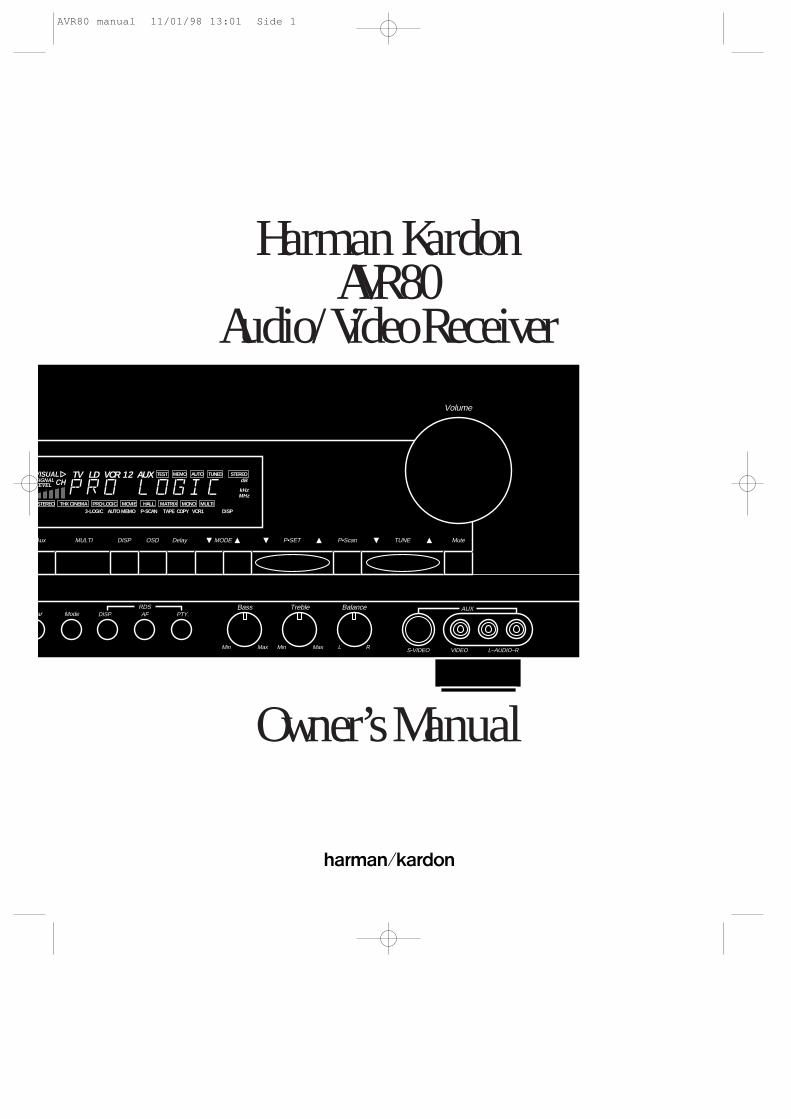
Harman KardonAVR80
Audio/VideoReceiver
Owner’s Manual
AVR80 manual 11/01/98 13:01 Side 1

Declaration of Conformity
We, Harman Kardon Europe A/S
Kongevejen 194B
DK-3460 Birkerød
DENMARK
declare in own responsibility, that the
product described in this owner's
manual is in compliance with
technical standards:
EN 55 013
EN 55 020
EN 55 022
EN 60 065
EN 60 555-2-3
Steen MichaelsenHarman Kardon Europe A/S
Birkerød, DENMARK11/95
AVR80 manual 11/01/98 13:01 Side 2
AVR80
AM/FM CD T-MON VCR 2T·2 TV LD VCR1 Aux MULTI DISP OSD Delay
BassModeClearPhonesPower MemoVCR1Tape1
Copy6-chdirectmode
Treble Balance
Volume
P•SET P•Scan TUNE
AUX
VIDEOS-VIDEORLMaxMinMaxMin L–AUDIO–R
MuteMODE
RDSDISP. AF PTY.
VISUALSIGNALLEVEL CH
TV LD VCR 12 AUX TEST
STEREO THX CINEMA PRO•LOGIC MOVIE HALL MATRIX MONO MULTI
MEMO AUTO TUNED STEREOdB
kHzMHz
3-LOGIC AUTO MEMO P-SCAN TAPE VCR1 DISPCOPY
12
3
Ó( Ô Ò Ú Û Ù ˘¯ ¸ˆ ˜ı
45 6 9 )! $ % ^
&
*
#87
VISUALSIGNALLEVEL CH
TV LD VCR 12 AUX TEST
STEREO THX CINEMA PRO•LOGIC MOVIE HALL MATRIX MONO MULTI
MEMO AUTO TUNED STEREOdB
kHzMHz
3-LOGIC AUTO MEMO P-SCAN TAPE VCR1 DISPCOPY
¡
fl
™ £ ¢ ∞ §
¶
•
ª¤‚‹›fi⁄
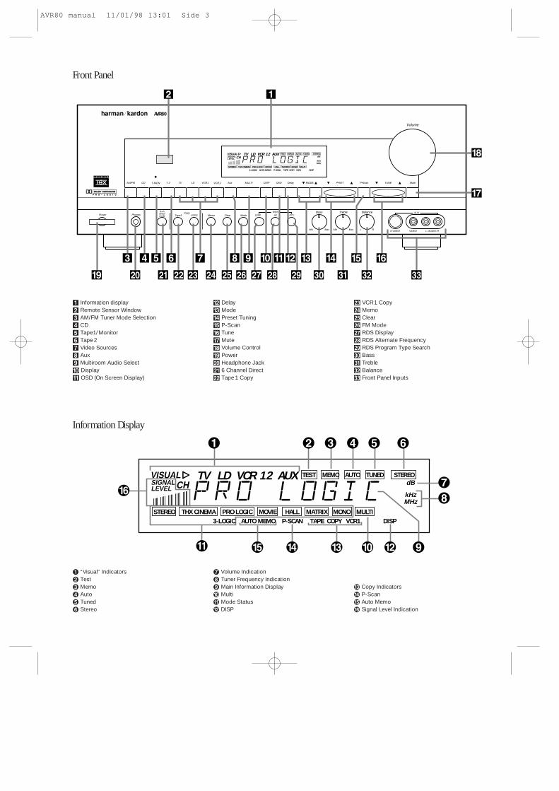
Front Panel
Information Display
¡ “Visual” Indicators™ Test£ Memo¢ Auto∞ Tuned§ Stereo
¶ Volume Indication• Tuner Frequency Indicationª Main Information Display‚ Multi⁄ Mode Status¤ DISP
‹ Copy Indicators› P-Scanfi Auto Memofl Signal Level Indication
1 Information display2 Remote Sensor Window3 AM/FM Tuner Mode Selection4 CD5 Tape1/Monitor6 Tape 27 Video Sources8 Aux9 Multiroom Audio Select) Display! OSD (On Screen Display)
@ Delay# Mode$ Preset Tuning% P-Scan^ Tune& Mute* Volume Control( PowerÓ Headphone JackÔ 6 Channel Direct Tape 1 Copy
Ò VCR1 CopyÚ MemoÛ ClearÙ FM Modeı RDS Displayˆ RDS Alternate Frequency˜ RDS Program Type Search¯ Bass˘ Treble¸ Balance˝ Front Panel Inputs
AVR80 manual 11/01/98 13:01 Side 3
OUT
TAPE2
IN
MULTIOUT
LD
TV
OUT
TAPE1
IN
CD
OUT
VCR2
IN
FRONT
CENTER
SURR.
8 OHMS
8 OHMS
FRONT
8 OHMS
RL
MAIN IN PRE OUTSURR.
CENTERSUBWOOFER
LDDIGITAL
IN
MULTI
OUT INREMOTECONT.
6-CHDIRECTINPUT
OUT
VCR1
IN
L
FRONT
R
L
SURR.
R
CENTER
SUBWOOFER
L R L RAUDIO R L
SPEAKERS
VIDEO S-VIDEO
FM(75Ω)
AM
ANTENNA
GND
TVMONI
OUT
VCR2
IN
OUT
VCR1
IN
LD
TV
®
†
ß
√ π
œ
∑µñ
˚
ü
ø
åç
∫¬
∆
î∂
ƒ
é
©
˙
SWITCHED UNSWITCHED
AC OUTLETS230V 50/60Hz)
OUT
TAPE2
IN
MULTIOUT
LD
TV
OUT
TAPE1
IN
CD
OUT
VCR2
IN
FRONT
CENTER
SURR.
8 OHMS
8 OHMS
FRONT
8 OHMS
RL
MAIN IN PRE OUTSURR.
CENTERSUBWOOFER
LDDIGITAL
IN
MULTI
OUT INREMOTECONT.
6-CHDIRECTINPUT
OUT
VCR1
IN
R
FRONT
L
R
SURR.
L
CENTER
SUBWOOFER
L R L RAUDIO R L
SPEAKERS
VIDEO S-VIDEO
FM(75Ω)
AM
ANTENNA
GND
TVMONI
OUT
VCR2
IN
OUT
VCR1
IN
LD
TV
S
UT
KI
LJ
ED
FC
RQ
ON
B
A
P
M
G
H
SWITCHED UNSWITCHED
AC OUTLETS230V 50/60Hz)
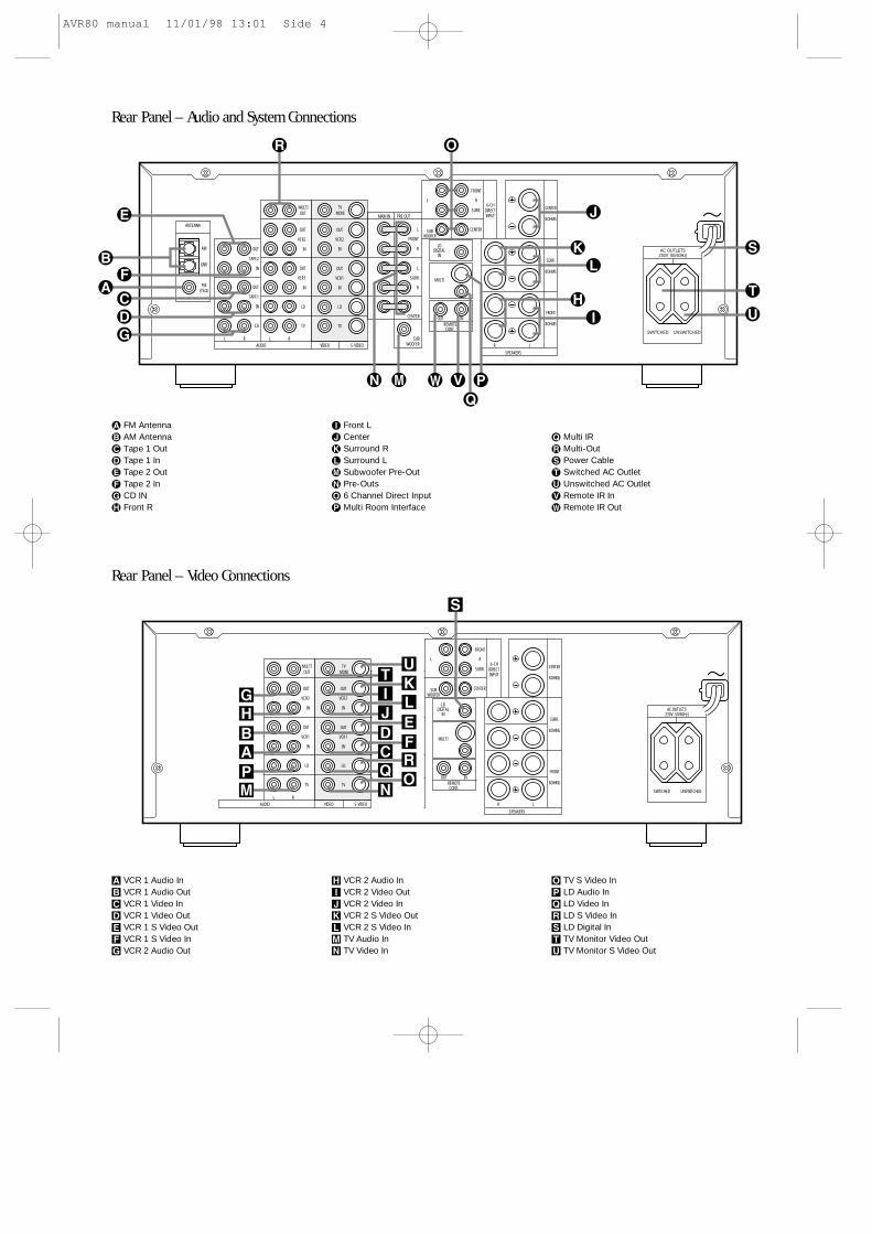
Rear Panel – Audio and System Connections
Rear Panel – Video Connections
A VCR 1 Audio InB VCR 1 Audio OutC VCR 1 Video InD VCR 1 Video OutE VCR 1 S Video OutF VCR 1 S Video InG VCR 2 Audio Out
H VCR 2 Audio InI VCR 2 Video OutJ VCR 2 Video InK VCR 2 S Video OutL VCR 2 S Video InM TV Audio InN TV Video In
O TV S Video InP LD Audio InQ LD Video InR LD S Video InS LD Digital InT TV Monitor Video OutU TV Monitor S Video Out
å FM Antenna∫ AM Antennaç Tape 1 Out∂ Tape 1 Iné Tape 2 Outƒ Tape 2 In© CD IN˙ Front R
î Front L∆ Center˚ Surround R¬ Surround Lµ Subwoofer Pre-Outñ Pre-Outsø 6 Channel Direct Inputπ Multi Room Interface
œ Multi IR® Multi-Outß Power Cable† Switched AC Outletü Unswitched AC Outlet√ Remote IR In∑ Remote IR Out
AVR80 manual 11/01/98 13:01 Side 4
Sending Learning
LearnUse
TV P/LOFF ON OFF ON
3 ST MOVIE
LD MATRIX HALL
CHANNEL/SKIP
REC
SELECT
SCREEN
DISPLAYPANEL
SPEAKER
DISPLAY NOISE
TEST ADJUST
DISCDECKANT.
TUNE/SEARCH
MUTE
STOP
STEREO
VCR1
TV MAIN
DELAY 1 2 3
VCR2 4 5 6
AUX PTY
AF
7 8 9
AM/FM
CD
Tape1(MON)
Tape2
V O L U M E
0
Source Power Main Power
ABC DEF GHI
JKL MNO PQR
STU VWX YZ_
MEMO CLEAR P•SCAN
THX
MONO
RDS
a
x
b
e
y
d
c
m
h
i
f
k
j
wu
s
q
t
gv
r
`
z
p
on
l
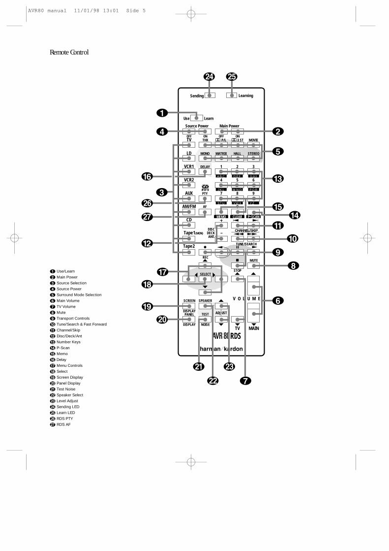
Remote Control
a Use/Learn
b Main Power
c Source Selection
d Source Power
e Surround Mode Selection
f Main Volume
g TV Volume
h Mute
i Transport Controls
j Tune/Search & Fast Forward
k Channel/Skip
l Disc/Deck/Ant
m Number Keys
n P-Scan
o Memo
p Delay
q Menu Controls
r Select
s Screen Display
t Panel Display
u Test Noise
v Speaker Select
w Level Adjust
x Sending LED
y Learn LED
z RDS PTY
` RDS AF
AVR80 manual 11/01/98 13:01 Side 5
Table of Contents
Introduction . . . . . . . . . . . . . . . . . . . . . . . . . . . . . . . . . . 1Features . . . . . . . . . . . . . . . . . . . . . . . . . . . . . . . . 1
Safety Information . . . . . . . . . . . . . . . . . . . . . . . . . . . . . 2 Unpacking and Installation . . . . . . . . . . . . . . . . 3Conventions. . . . . . . . . . . . . . . . . . . . . . . . . . . . . 3
Front Panel Controls . . . . . . . . . . . . . . . . . . . . . . . . . . . . 4Front Panel Information Display . . . . . . . . . . . . . . . . . . 5Rear Panel Audio & Systems Connections . . . . . . . . . . . 6Rear Panel Video Connections . . . . . . . . . . . . . . . . . . . . 7Remote Control Functions . . . . . . . . . . . . . . . . . . . . . 8–9Installation, Set Up and Configuration . . . . . . . . . 10–12Remote Control Programming and Operation . . . 13–14System Configuration. . . . . . . . . . . . . . . . . . . . . . . 15–18Basic Operation . . . . . . . . . . . . . . . . . . . . . . . . . . . 19–24
Source Selection . . . . . . . . . . . . . . . . . . . . . . . . 19Volume Control . . . . . . . . . . . . . . . . . . . . . . . . . 19Surround Mode Selection . . . . . . . . . . . . . . . . . 19TV Auto Function . . . . . . . . . . . . . . . . . . . . . . . 20Tuner Operation. . . . . . . . . . . . . . . . . . . . . 20–22RDS Operation . . . . . . . . . . . . . . . . . . . . . . 23–24
On Screen Display . . . . . . . . . . . . . . . . . . . . . . . . . . 25–27Advanced Functions . . . . . . . . . . . . . . . . . . . . . . . . 28–31
Audio Tape Dubbing . . . . . . . . . . . . . . . . . . . . . 28Video Dubbing. . . . . . . . . . . . . . . . . . . . . . . . . . 28Audio/Video Simulcast Recording . . . . . . . 28–29Delay Time Adjust . . . . . . . . . . . . . . . . . . . . . . . 29Direct Digital Decoding . . . . . . . . . . . . . . . 29–306 Channel Direct Operation . . . . . . . . . . . . . . . 30Surround Mode Chart . . . . . . . . . . . . . . . . . . . . 31
Multiroom Operation . . . . . . . . . . . . . . . . . . . . . . . 32–34Troubleshooting Chart . . . . . . . . . . . . . . . . . . . . . . . . . 35System Reset . . . . . . . . . . . . . . . . . . . . . . . . . . . . . . . . . 35Technical Specifications . . . . . . . . . . . . . . . . . . . . . . . . 36
AVR80 manual 11/01/98 13:01 Side 6
EN
GLIS
H
Introduction1
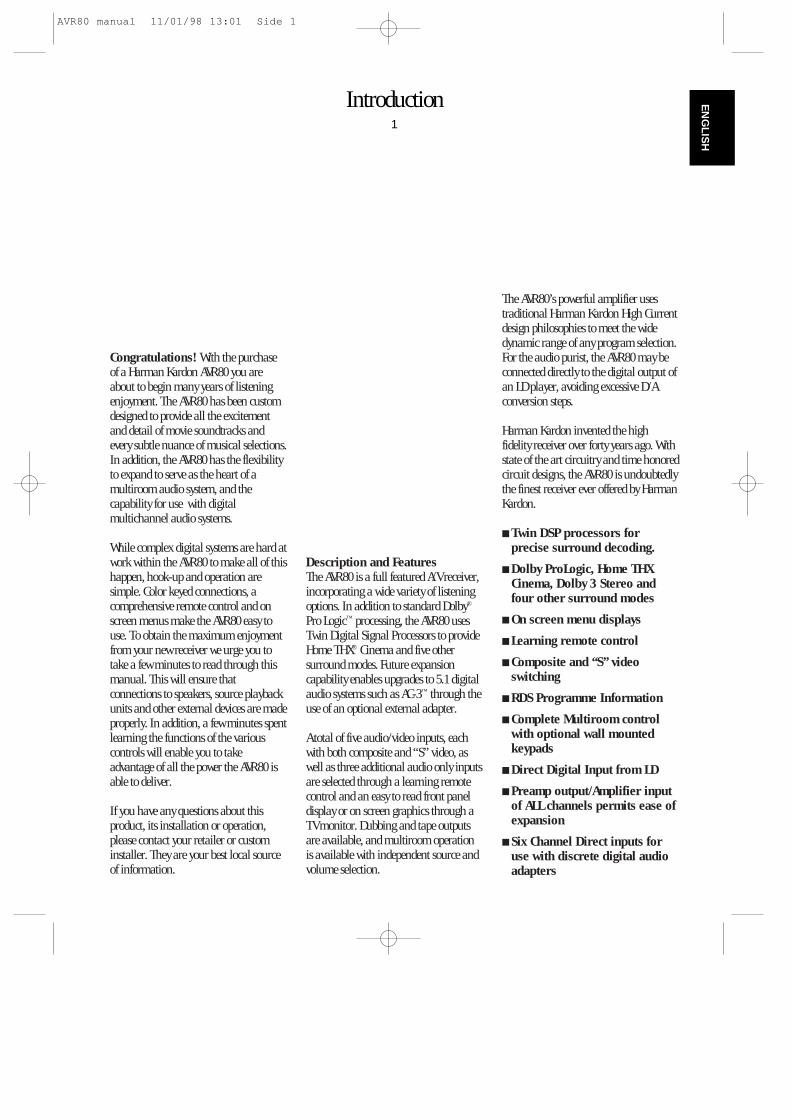
Congratulations! With the purchaseof a Harman Kardon AVR80 you areabout to begin many years of listeningenjoyment. The AVR80 has been customdesigned to provide all the excitementand detail of movie soundtracks andevery subtle nuance of musical selections.In addition, the AVR80 has the flexibilityto expand to serve as the heart of amultiroom audio system, and thecapability for use with digitalmultichannel audio systems.
While complex digital systems are hard atwork within the AVR80 to make all of thishappen, hook-up and operation aresimple. Color keyed connections, acomprehensive remote control and onscreen menus make the AVR80 easy touse. To obtain the maximum enjoymentfrom your new receiver we urge you totake a few minutes to read through thismanual. This will ensure thatconnections to speakers, source playbackunits and other external devices are madeproperly. In addition, a few minutes spentlearning the functions of the variouscontrols will enable you to takeadvantage of all the power the AVR80 isable to deliver.
If you have any questions about thisproduct, its installation or operation,please contact your retailer or custominstaller. They are your best local sourceof information.
Description and FeaturesThe AVR80 is a full featured A/V receiver,incorporating a wide variety of listeningoptions. In addition to standard Dolby®
Pro Logic™ processing, the AVR80 usesTwin Digital Signal Processors to provideHome THX® Cinema and five othersurround modes. Future expansioncapability enables upgrades to 5.1 digitalaudio systems such as AC-3™ through theuse of an optional external adapter.
A total of five audio/video inputs, eachwith both composite and “S” video, aswell as three additional audio only inputsare selected through a learning remotecontrol and an easy to read front paneldisplay or on screen graphics through aTV monitor. Dubbing and tape outputsare available, and multiroom operationis available with independent source andvolume selection.
The AVR80’s powerful amplifier usestraditional Harman Kardon High Currentdesign philosophies to meet the widedynamic range of any program selection.For the audio purist, the AVR80 may beconnected directly to the digital output ofan LD player, avoiding excessive D/Aconversion steps.
Harman Kardon invented the highfidelity receiver over forty years ago. Withstate of the art circuitry and time honoredcircuit designs, the AVR80 is undoubtedlythe finest receiver ever offered by HarmanKardon.
Twin DSP processors forprecise surround decoding.
Dolby ProLogic, Home THXCinema, Dolby 3 Stereo andfour other surround modes
On screen menu displays
Learning remote control
Composite and “S” videoswitching
RDS Programme Information
Complete Multiroom controlwith optional wall mountedkeypads
Direct Digital Input from LD
Preamp output/Amplifier inputof ALL channels permits ease ofexpansion
Six Channel Direct inputs foruse with discrete digital audioadapters
AVR80 manual 11/01/98 13:01 Side 1
Installation Location To assure proper operation, and to
avoid the potential for safety hazards,place the unit on a firm and levelsurface. When placing the unit on ashelf, be certain that the shelf and anymounting hardware can support theweight of the product.
Make certain that proper space isprovided both above and below the unitfor ventilation. If this product will beinstalled in a cabinet or other enclosedarea, make certain that there issufficient air movement within thecabinet. Under some circumstances afan may be required.
Do not place the unit directly on acarpeted surface.
Avoid installation in extremely hot orcold locations, or an area that isexposed to direct sunlight or heatingequipment.
Avoid moist or humid locations.
Do not obstruct the ventilation slots onthe top of the unit, or place objectsdirectly over them.
Safety Information2
EN
GLI
SH
Important Safety Information
Verify Line Voltage Before UseYour AVR80 has been designed for usewith 220–240 volt AC current.Connection to a line voltage other thanthat for which it is intended can create asafety and fire hazard, and may damagethe unit.
If you have any questions about thevoltage requirements for your specificmodel, or about the line voltage in yourarea, contact your selling dealer beforeplugging the unit into a wall outlet.
Do Not Use Extension CordsTo avoid safety hazards, use only thepower cord attached to your unit. We donot recommend that extension cords beused with this product. As with allelectrical devices, do not run power cordsunder rugs or carpets or place heavyobjects on them.
Handle the AC Power Cord GentlyWhen disconnecting the power cord froman AC outlet, always pull the plug, neverpull the cord. If you do not intend to usethe unit for any considerable length oftime, disconnect the plug from the ACoutlet.
Do Not Open The CabinetThere are no user serviceable componentsinside this product. Opening the cabinetmay present a shock hazard, and anymodification to the product will void yourguarantee. If water or any metal objectsuch as a paper clip, wire or a stapleaccidentally falls inside the unit,disconnect it from the AC power sourceimmediately, and consult an authorizedservice station.
CleaningWhen the unit gets dirty, wipe it with aclean, soft dry cloth. If necessary, wipe itwith a soft cloth dampened with mildsoapy water, then a fresh cloth with cleanwater. Wipe dry immediately with a drycloth. NEVER use benzene, aerosolcleaners, thinner, alcohol or any othervolatile cleaning agent. Do not useabrasive cleaners, as they may damagethe finish of metal parts. Avoid sprayinginsecticide near the unit.
Moving The UnitBefore moving the unit, be certain todisconnect any interconnection cordswith other components, and make certainthat you disconnect the unit from the ACoutlet.
AVR80 manual 11/01/98 13:01 Side 2
Safety Information3
EN
GLIS
H
Unpacking and Installation
The carton and shipping materials usedto protect your new receiver duringshipment were specially designed tocushion it from shock and vibration. Wesuggest that you save the carton andpacking materials for use in shipping ifyou move or should the unit ever needrepair.
To minimize the size of the carton instorage, you may wish to flatten it. This isdone by carefully slitting the tape seamson the bottom and collapsing the cartondown to a more two dimensionalappearance. Other cardboard inserts maybe stored in the same manner. Packingmaterials that cannot be collapsed shouldbe saved along with the carton in aplastic bag.
If you do not wish to save the packagingmaterials, please note that the carton andother sections of the shipping protectionare recyclable. Please respect theenvironment and discard those materialsat a local recycling center.
Important Fuse and Plug Information
This apparatus is fitted with an approvedmoulded 13 Amp plug. To change a fusein this type of plug proceed as follows:
1. Remove fuse cover and fuse.
2. Fix new fuse which should be a BS13625A A.S.T.A. or BSI approved type.
3. Refit the fuse cover.
If the fitted plug is not suitable for yoursocket outlets, it should be cut off and anappropriate plug fitted in its place.
If the mains plug contains a fuse, thisshould have a value of 5A.
If a plug without a fuse is used, the fuseat the distribution board should not begreater than 5A.
NOTE: The severed plug must bedestroyed to avoid a possible shock hazard should it be inserted into a 13Asocket elsewhere.
How to Connect a PlugThe wires in the mains lead are colouredin accordance with the following code:
BLUE – “NEUTRAL” (“N”)
BROWN – “LIVE” (“L”)
1. The BLUE wire must be connected tothe terminal which is marked with theletter “N” or coloured BLACK.
2. The BROWN wire must be connected tothe terminal which is marked with theletter “L” or coloured RED.
3. Do not connect either wires to the earthterminal in the plug which is marked mythe letter “E” or by the safety earthsymbol or coloured green or green-and-yellow.
Before replacing the plug cover, makecertain that the cord grip is clamped overthe sheath of the lead – not simply overthe two wires.
Conventions
In order to help you use this manual withthe remote control, front panel controls, rear panel connections and on-screen menus, certain conventionshave been used.
EXAMPLE – (bold type) indicates aspecific remote control or front panelbutton, or rear panel connection jack
EXAMPLE – (OCR type) indicates amessage that is visible through the on-screen menu system
1 – (number in a square) indicates aspecific front panel control
¡ – (number in a circle) indicates anindicator in the main front panel display
a – (number in an oval) indicates abutton or indicator on the remote
å – (letter in a circle) indicates a rearpanel Audio or System connection
A – (letter in a square) indicates a specific rear panel video connection
AVR80 manual 11/01/98 13:01 Side 3
Front Panel Controls4
EN
GLI
SH
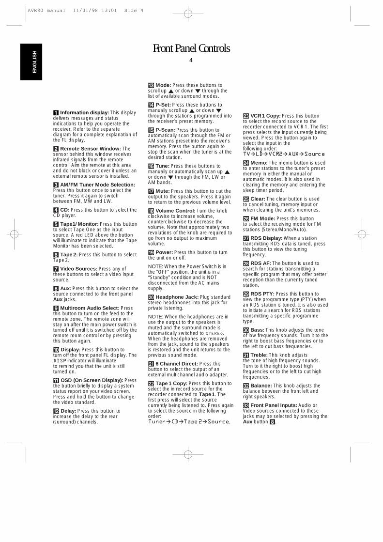
1 Information display: This displaydelivers messages and statusindications to help you operate thereceiver. Refer to the separatediagram for a complete explanation ofthe FL display.
2 Remote Sensor Window: Thesensor behind this window receivesinfrared signals from the remotecontrol. Aim the remote at this areaand do not block or cover it unless anexternal remote sensor is installed.
3 AM/FM Tuner Mode Selection:Press this button once to select thetuner. Press it again to switchbetween FM, MW and LW.
4 CD: Press this button to select theCD player.
5 Tape1/Monitor: Press this buttonto select Tape One as the inputsource. A red LED above the buttonwill illuminate to indicate that the TapeMonitor has been selected.
6 Tape 2: Press this button to selectTape 2.
7 Video Sources: Press any ofthese buttons to select a video inputsource.
8 Aux: Press this button to select thesource connected to the front panelAux jacks.
9 Multiroom Audio Select: Pressthis button to turn on the feed to theremote zone. The remote zone willstay on after the main power switch isturned off until it is switched off by theremote room control or by pressingthis button again.
) Display: Press this button toturn off the front panel FL display. TheDISP indicator will illuminateto remind you that the unit is stillturned on.
! OSD (On Screen Display): Pressthe button briefly to display a systemstatus report on your video screen.Press and hold the button to changethe video standard.
@ Delay: Press this button toincrease the delay to the rear(surround) channels.
# Mode: Press these buttons toscroll up ⁄ or down ¤ through thelist of available surround modes.
$ P-Set: Press these buttons tomanually scroll up ⁄ or down ¤through the stations programmed intothe receiver’s preset memory.
% P-Scan: Press this button toautomatically scan through the FM orAM stations preset into the receiver’smemory. Press the button again tostop the scan when the tuner is at thedesired station.
^ Tune: Press these buttons tomanually or automatically scan up ⁄or down ¤ through the FM, LW orAM bands.
& Mute: Press this button to cut theoutput to the speakers. Press it againto return to the previous volume level.
* Volume Control: Turn the knobclockwise to increase volume,counterclockwise to decrease thevolume. Note that approximately tworevolutions of the knob are required togo from no output to maximumvolume.
( Power: Press this button to turnthe unit on or off.
NOTE: When the Power Switch is inthe “OFF” position, the unit is in a“Standby” condition and is NOTdisconnected from the AC mainssupply.
Ó Headphone Jack: Plug standardstereo headphones into this jack forprivate listening.
NOTE: When the headphones are inuse the output to the speakers ismuted and the surround mode isautomatically switched to STEREO.When the headphones are removedfrom the jack, sound to the speakersis restored and the unit returns to theprevious sound mode.
Ô 6 Channel Direct: Press thisbutton to select the output of anexternal multichannel audio adapter.
Tape 1 Copy: Press this button toselect the in record source for therecorder connected to Tape1. Thefirst press will select the sourcecurrently being listened to. Press againto select the source in the followingorder:Tuner‡CD‡Tape2‡Source.
Ò VCR1 Copy: Press this button to select the record source to therecorder connected to VCR1. The first press selects the input currently beingviewed. Press the button again toselect the input in the following order:TV‡LD‡VCR2‡AUX‡Source
Ú Memo: The memo button is usedto enter stations to the tuner’s presetmemory in either the manual orautomatic modes. It is also used inclearing the memory and entering thesleep timer period.
Û Clear: The clear button is used to cancel tuning, memory input orwhen clearing the unit’s memories.
Ù FM Mode: Press this button to select the receiving mode for FM stations (Stereo/Mono/Auto).
ı RDS Display: When a stationtransmitting RDS data is tuned, pressthis button to view the tuningfrequency.
ˆ RDS AF: The button is used tosearch for stations transmitting aspecific program that may offer betterreception than the currently tunedstation.
˜ RDS PTY: Press this button toview the programme type (PTY) whenan RDS station is tuned. It is also usedto initiate a search for RDS stationstransmitting a specific programmetype.
¯ Bass: This knob adjusts the toneof low frequency sounds. Turn it to theright to boost bass frequencies or tothe left to cut bass frequencies.
˘ Treble: This knob adjusts the tone of high frequency sounds. Turn to it the right to boost high frequencies or to the left to cut highfrequencies.
¸ Balance: This knob adjusts thebalance between the front left andright speakers.
˝ Front Panel Inputs: Audio orVideo sources connected to thesejacks may be selected by pressing theAux button 8.
AVR80 manual 11/01/98 13:01 Side 4
Front Panel Information Display5
EN
GLIS
H
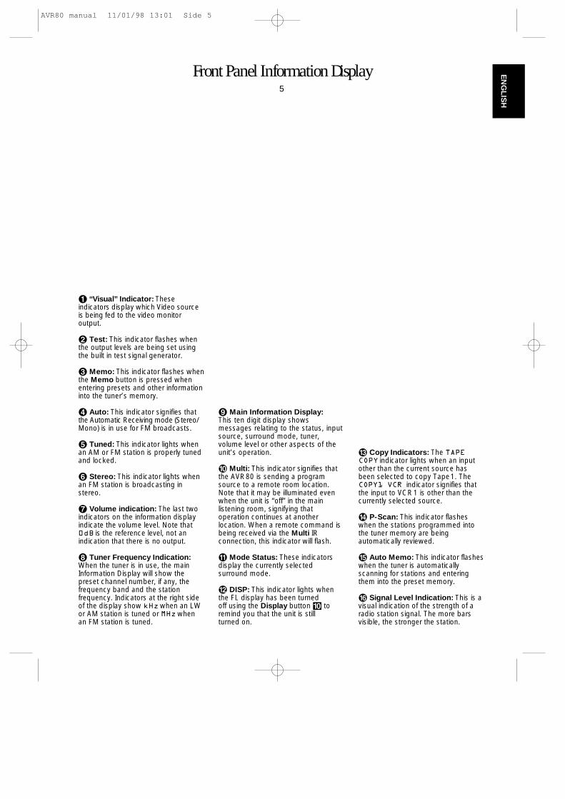
¡ “Visual” Indicator: Theseindicators display which Video sourceis being fed to the video monitoroutput.
™ Test: This indicator flashes whenthe output levels are being set usingthe built in test signal generator.
£ Memo: This indicator flashes whenthe Memo button is pressed whenentering presets and other informationinto the tuner’s memory.
¢ Auto: This indicator signifies thatthe Automatic Receiving mode (Stereo/Mono) is in use for FM broadcasts.
∞ Tuned: This indicator lights whenan AM or FM station is properly tunedand locked.
§ Stereo: This indicator lights whenan FM station is broadcasting instereo.
¶ Volume indication: The last twoindicators on the information displayindicate the volume level. Note that0dB is the reference level, not anindication that there is no output.
• Tuner Frequency Indication:When the tuner is in use, the mainInformation Display will show thepreset channel number, if any, thefrequency band and the stationfrequency. Indicators at the right sideof the display show kHzwhen an LWor AM station is tuned or MHzwhenan FM station is tuned.
ª Main Information Display:This ten digit display showsmessages relating to the status, inputsource, surround mode, tuner,volume level or other aspects of theunit’s operation.
‚ Multi: This indicator signifies thatthe AVR80 is sending a programsource to a remote room location.Note that it may be illuminated evenwhen the unit is “off” in the mainlistening room, signifying thatoperation continues at anotherlocation. When a remote command isbeing received via the Multi IRconnection, this indicator will flash.
⁄ Mode Status: These indicatorsdisplay the currently selected surround mode.
¤ DISP: This indicator lights whenthe FL display has been turned off using the Display button ) toremind you that the unit is still turned on.
‹ Copy Indicators: The TAPECOPY indicator lights when an inputother than the current source hasbeen selected to copy Tape1. TheCOPY1 VCR indicator signifies thatthe input to VCR1 is other than thecurrently selected source.
› P-Scan: This indicator flasheswhen the stations programmed intothe tuner memory are beingautomatically reviewed.
fi Auto Memo: This indicator flasheswhen the tuner is automaticallyscanning for stations and enteringthem into the preset memory.
fl Signal Level Indication: This is avisual indication of the strength of aradio station signal. The more barsvisible, the stronger the station.
AVR80 manual 11/01/98 13:01 Side 5
Rear Panel Audio and System Connections6
EN
GLI
SH
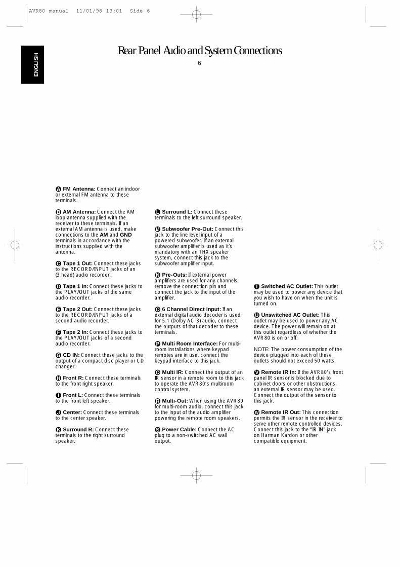
å FM Antenna: Connect an indooror external FM antenna to these terminals.
∫ AM Antenna: Connect the AMloop antenna supplied with thereceiver to these terminals. If anexternal AM antenna is used, makeconnections to the AM and GNDterminals in accordance with theinstructions supplied with theantenna.
ç Tape 1 Out: Connect these jacksto the RECORD/INPUT jacks of an (3 head) audio recorder.
∂ Tape 1 In: Connect these jacks tothe PLAY/OUT jacks of the sameaudio recorder.
é Tape 2 Out: Connect these jacksto the RECORD/INPUT jacks of asecond audio recorder.
ƒ Tape 2 In: Connect these jacks tothe PLAY/OUT jacks of a secondaudio recorder.
© CD IN: Connect these jacks to theoutput of a compact disc player or CDchanger.
˙ Front R: Connect these terminalsto the front right speaker.
î Front L: Connect these terminalsto the front left speaker.
∆ Center: Connect these terminalsto the center speaker.
˚ Surround R: Connect theseterminals to the right surroundspeaker.
¬ Surround L: Connect theseterminals to the left surround speaker.
µ Subwoofer Pre-Out: Connect thisjack to the line level input of apowered subwoofer. If an externalsubwoofer amplifier is used as it´smandatory with an THX speakersystem, connect this jack to thesubwoofer amplifier input.
ñ Pre-Outs: If external poweramplifiers are used for any channels,remove the connection pin andconnect the jack to the input of theamplifier.
ø 6 Channel Direct Input: If anexternal digital audio decoder is usedfor 5.1 (Dolby AC-3) audio, connectthe outputs of that decoder to theseterminals.
π Multi Room Interface: For multi-room installations where keypadremotes are in use, connect thekeypad interface to this jack.
œ Multi IR: Connect the output of anIR sensor in a remote room to this jackto operate the AVR80’s multiroomcontrol system.
® Multi-Out: When using the AVR80for multi-room audio, connect this jackto the input of the audio amplifierpowering the remote room speakers.
ß Power Cable: Connect the ACplug to a non-switched AC wall output.
† Switched AC Outlet: This outletmay be used to power any device thatyou wish to have on when the unit isturned on.
ü Unswitched AC Outlet: Thisoutlet may be used to power any ACdevice. The power will remain on atthis outlet regardless of whether theAVR80 is on or off.
NOTE: The power consumption of thedevice plugged into each of theseoutlets should not exceed 50 watts.
√ Remote IR In: If the AVR80’s frontpanel IR sensor is blocked due tocabinet doors or other obstructions,an external IR sensor may be used.Connect the output of the sensor tothis jack.
∑ Remote IR Out: This connectionpermits the IR sensor in the receiver toserve other remote controlled devices.Connect this jack to the “IR IN” jackon Harman Kardon or othercompatible equipment.
AVR80 manual 11/01/98 13:01 Side 6
Rear Panel Video Connections7
EN
GLIS
H
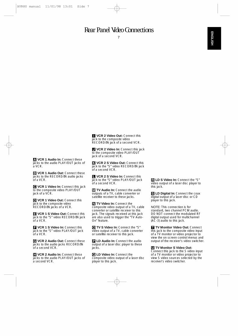
A VCR 1 Audio In: Connect thesejacks to the audio PLAY/OUT jacks ofa VCR.
B VCR 1 Audio Out: Connect thesejacks to the RECORD/IN audio jacksof a VCR.
C VCR 1 Video In: Connect this jackto the composite video PLAY/OUTjack of a VCR.
D VCR 1 Video Out: Connect thisjack to the composite videoRECORD/IN jacks of a VCR.
E VCR 1 S Video Out: Connect thisjack to the “S” video RECORD/IN jackof a VCR.
F VCR 1 S Video In: Connect thisjack to the “S” video PLAY/OUT jackof a VCR.
G VCR 2 Audio Out: Connect thesejacks to the audio jacks RECORD/INof a second VCR.
H VCR 2 Audio In: Connect thesejacks to the audio PLAY/OUT jacks ofa second VCR.
I VCR 2 Video Out: Connect thisjack to the composite videoRECORD/IN jack of a second VCR.
J VCR 2 Video In: Connect this jackto the composite video PLAY/OUTjack of a second VCR.
K VCR 2 S Video Out: Connect thisjack to the “S” video RECORD/IN jackof a second VCR.
L VCR 2 S Video In: Connect thisjack to the “S” video PLAY/OUT jackof a second VCR.
M TV Audio In: Connect the audiooutputs of a TV, cable converter orsatellite receiver to these jacks.
N TV Video In: Connect thecomposite video output of a TV, cableconverter or satellite receiver to thisjack. The signals received at this jackare also used to trigger the “TV Auto-On” feature.
O TV S Video In: Connect the “S”video output of a TV, cable converteror satellite receiver to this jack.
P LD Audio In: Connect the audiooutput of a laser disc player to thesejacks.
Q LD Video In: Connect thecomposite video output of a laser discplayer to this jack.
R LD S Video In: Connect the “S”video output of a laser disc player tothis jack.
S LD Digital In: Connect the coaxdigital output of a laser disc or CDplayer to this jack.
NOTE: This connection is forstandard, two channel PCM audio.DO NOT connect the modulated RFdigital output used for multichannel(AC-3) audio to this jack.
T TV Monitor Video Out: Connectthis jack to the composite video inputof a TV monitor or video projector toview the on screen control menus andoutput of the receiver’s video switcher.
U TV Monitor S Video Out:Connect this jack to the S video inputof a TV monitor or video projector toview S video sources selected by thereceiver’s video switcher.
AVR80 manual 11/01/98 13:01 Side 7
Remote Control Functions8
EN
GLI
SH
a Use/Learn: This switch selectsthe operation mode of the remotecontrol. Slide it to the left for normaloperation. Slide it to the right when theremote is being programmed.
b Main Power: Press these buttons to turn the unit on or off.
c Source Selection: Pressing oneof these buttons selects the inputsource that will be listened to throughthe receiver. When a source isselected the remote’s transport andnumeric number buttons will alsotransmit the commands needed tocontrol that machine.
d Source Power: Press thesebuttons to control power for the lastsource device selected. This is effective only for devices withremoteable power (not TU930, HD730),for tapes only with input Tape 1 (Monitor)unless programmed otherwise.
e Surround Mode Selection:Press one of these buttons to select asurround mode for the currentlistening session.
f Main Volume: These buttonscontrol the unit’s volume. Note that allchannels are controlledsimultaneously.
g TV Volume: These buttons adjustthe volume for TV using the remotecontrol codes programmed into theremote for a TV set or cable box.These buttons control the TV set only,regardless of which source isselected. This enables you to controlthe audio level of a TV set even whenthe receiver is not in use.
h Mute: Press this button totemporarily cut the audio output of thereceiver. Press it again to return to theprevious volume level.
i Transport Controls: These buttons control the tape or discmotion of the last playback sourceselected with the Source Selectionbuttons c. Use them as you wouldthe Play, Stop, Pause, Reverse Playand Record buttons on any VCR, CDcassette deck or LD remote control.
j Tune/Search & Fast Forward:(These buttons have multiplefunctions, which vary according to theinput device selected.)
a. When the TUNER has beenselected, these buttons are used totune stations.
b. When CD, LD, Tape or VCR is theinput source, these buttons act as the Fast Scan Forward —or Fast Scan Reverse ‚controls.
k Channel/Skip: (These buttonshave multiple functions, whichvary according to the input deviceselected.)
a. When the TUNER has beenselected, these buttons will scroll up· or down ‡ through the stations that have beenprogrammed in the preset memory.
b. When TV or VCR is selected, theyare the channel up · or channeldown ‡ tuning buttons.
c. When CD or LD is selected thesebuttons act as forward and reverse“Skip” buttons to move to the nexttrack or chapter on the disc.
d. When a compatible Harman Kardoncassette player has been selectedas Tape 1 or Tape 2, thesebuttons move the tape forward ·or backwards ‡ to the nextselection using the Music Scanfeature.
l Disc/Deck/Ant: (These buttonshave multiple functions, whichvary according to the input deviceselected.)
a. When CD is selected and the unit isa CD changer, these buttons willchange to the next disc ∏ orprevious disc Â.
b. When Tape 1 or Tape 2 is theinput source, and the tape machineis a dual cassette deck, thesebuttons will switch between the “A”and “B” sides if programmedcorrespondingly.
c. When VCR 1 or VCR 2 is the inputsource, these buttons switchbetween tape and TV-tuner as theVCR’s output.
d. When TV is the input source, thesebuttons may switch between videoinput sources or antenna/video,depending on the TV model.
e. When LD is the input source, thesebuttons will switch the side beingplayed from “A” to “B” oncompatible dual side players.
m Number Keys: These buttonsserve as a ten button numeric keypadto enter tuner preset positions. Theyare also to be used to select channelnumbers when TV has been selectedon the remote, or to select tracknumbers on a CD or LD player, if CDor LD has been selected by theremote. The letters below the buttonsare used to enter information for tunerstation names.
NOTE: The 0 button has a dualfunction. It also serves as the CLEARbutton for use in programming thetuner or clearing the system memory.
AVR80 manual 11/01/98 13:01 Side 8
Remote Control Functions9
EN
GLIS
H
n P-Scan: Press this button toautomatically scan through thestations preset into the tuner memory.Press the button again to end thescan when the tuner stops at thedesired station.
o Memo: The memo button is usedto enter stations to the tuner’s presetmemory in either the manual orautomatic modes. It is also used in theprocess of clearing the memory.
p Delay: This button controls theamount of sound delay to the rear(surround) channels. Press it toincrease the delay in the steps shownin the main Information Display oron-screen graphics.
q Menu Controls: These buttonscontrol the action of the cursor or theselection of menu items when thereceiver is being configured using thesetup menus.
r Select: This button chooses amenu and enters settings to thereceiver’s memory during systemconfiguration.
s Screen Display: Press thisbutton to activate the on screen menusystem.
t Panel Display: Press this buttonto turn off all displays and indicators inthe Information Display except for asmall DISP indication in the lowerright corner of the display ¤ Press thebutton again to turn the display backon. Note that the display will brieflyilluminate when a command is sent tothe unit from the front panel or remote,even though the display is turned off.
u Test Noise: Press this button tobegin calibration of the output level foreach channel. A test signal willimmediately be heard from the leftfront speaker and the TEST indicator™ will flash.
v Speaker Select: When settingthe system output levels, this buttonselects the speaker position beingadjusted. Press it once to advance tothe next speaker after each position isadjusted.
w Level Adjust: When setting thesystem output levels, press thesebuttons in increase or decrease theoutput level.
x Sending LED: This indicatorshould flash any time a button ispressed to confirm that a command isbeing sent to the receiver or anotherunit. If the light is dim or does notilluminate when a button is pressed thebatteries in the remote should bereplaced.
y Learn LED: This indicator willilluminate when a button on theremote is being programmed withsignals from another remote duringthe “learning” mode. The light will goout when the signal is received andmemorized.
z RDS PTY: Press this button toview the Programme Type informationfor stations transmitting RDS data.This button is also used for PTY AutoSearch functions.
` RDS AF: This button initiates asearch of alternate frequencies to findan eventually stronger signal for thestation type currently selected.
AVR80 manual 11/01/98 13:01 Side 9
Installation, Set Up & Configuration10
EN
GLI
SH
System InstallationAfter unpacking the unit, and placing itin on a solid surface capable ofsupporting its weight, you will need tomake the connections to your audio andvideo equipment. These steps need to bedone only when the receiver is firstinstalled, or when a change is made tothe input source equipment.
Audio Input and OutputConnectionsUse the “Audio and SystemsConnections” Diagram in the inside frontcover as a guide to connecting audiocomponents and speakers to the rearpanel. We recommend that you use highquality cables when making connectionsto source equipment and recorders topreserve the quality of the signals.
NOTE: When making connections toaudio source equipment or speakers it isalways a good practice to unplug the unitfrom the AC wall plug. This prevents anypossibility of accidentally sending audioor transient signals to the speakers thatmay damage them.
1. For playback only sources, such as aCD player, CD changer, external phonopreamp or external digital to analogconverter, connect the output jacks of theplayer to the appropriately labeled inputson the rear panel. ©
NOTE: When the source device has bothfixed and variable audio outputs it is bestto use the fixed output unless you findthat the input to the receiver is so lowthat the sound is noisy, or high that thesignal is distorted.
2. When connecting recording devicessuch as cassette recorders, open reel tapedecks, DCC, DAT or MD, connect thePLAY/OUT jacks of the recorder to the INjacks ∂ƒ. Connect the RECORD/INjacks on the recorder to the OUT jacksçé.
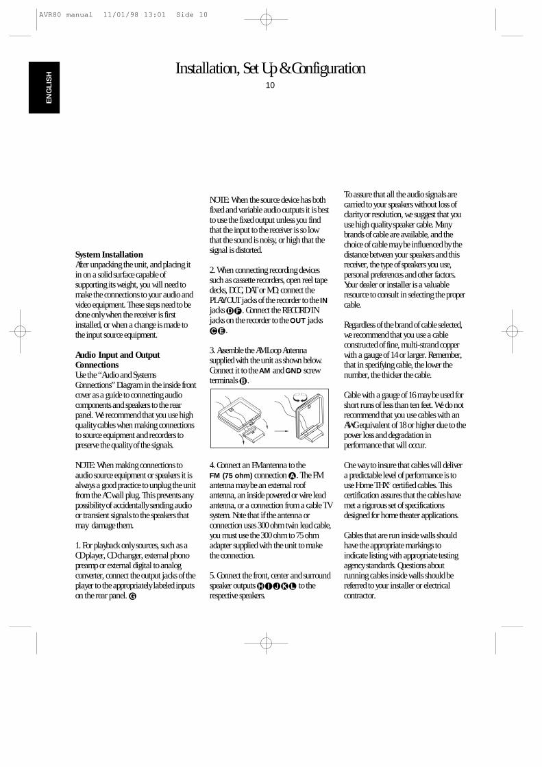
3. Assemble the AM Loop Antennasupplied with the unit as shown below.Connect it to the AM and GND screwterminals ∫.
4. Connect an FM antenna to the FM (75 ohm) connection å. The FMantenna may be an external roofantenna, an inside powered or wire leadantenna, or a connection from a cable TVsystem. Note that if the antenna orconnection uses 300 ohm twin lead cable,you must use the 300 ohm to 75 ohmadapter supplied with the unit to makethe connection.
5. Connect the front, center and surroundspeaker outputs ˙î∆˚¬ to therespective speakers.
To assure that all the audio signals arecarried to your speakers without loss ofclarity or resolution, we suggest that youuse high quality speaker cable. Manybrands of cable are available, and thechoice of cable may be influenced by thedistance between your speakers and thisreceiver, the type of speakers you use,personal preferences and other factors.Your dealer or installer is a valuableresource to consult in selecting the propercable.
Regardless of the brand of cable selected,we recommend that you use a cableconstructed of fine, multi-strand copperwith a gauge of 14 or larger. Remember,that in specifying cable, the lower thenumber, the thicker the cable.
Cable with a gauge of 16 may be used forshort runs of less than ten feet. We do notrecommend that you use cables with anAWG equivalent of 18 or higher due to thepower loss and degradation inperformance that will occur.
One way to insure that cables will delivera predictable level of performance is touse Home THX® certified cables. Thiscertification assures that the cables havemet a rigorous set of specificationsdesigned for home theater applications.
Cables that are run inside walls shouldhave the appropriate markings toindicate listing with appropriate testingagency standards. Questions aboutrunning cables inside walls should bereferred to your installer or electricalcontractor.
AVR80 manual 11/01/98 13:01 Side 10
Installation, Set Up & Configuration11
EN
GLIS
H
When connecting wires to the speakers,be certain to observe proper polarity.Remember to connect the “negative” or“black” wire to the same terminal on thereceiver and the speaker. Similary the“Red“ wire should be connected to thelike terminal on the AVR80 and speaker.
NOTE: While most speakermanufacturers adhere to an industryconvention of using black terminals fornegative and red ones for positive, somemanufacturers may vary from thisconfiguration. To assure proper phase,and optimal performance, consult theidentification plate on your speaker, orthe speaker’s manual to verify polarity. Ifyou do not know the polarity of yourspeaker, ask your dealer for advice beforeproceeding, or consult the speaker’smanufacturer.
6. Connections to a subwoofer are madevia a line level audio connection from thereceiver´s jack µ to the line level input ofa subwoofer with a built in amplifier. If apassive subwoofer is used, the connectionfirst goes to a power amplifier, which willbe connected to the subwoofer speakers.
If Your system has two subwoofers, aswith many THX systems, connect the jackµ with a so called ‘Y’ cable to a Stereopower amplifier, powering bothsubwoofers.
7. If an outboard multichannel digitalaudio adapter is used, connect the sixoutputs of the adapter to the 6 CH.Direct Input inputs ø.
Video Input and Output ConnectionsVideo connections are made in a similarfashion to those for audio components.Again, the use of high qualityinterconnect video cables isrecommended to preserve signal quality.
1. Connect the VCR’s audio, video and“S” Video OUT jacks to the VCR IN jacksACFHJL on the rear panel. Theaudio, video and “S” video IN jacks onthe VCR should be connected to the VCROUT jacks BDEGIK on the AVR80.
2. Connect the audio, video and “S” videooutputs of a satellite receiver, cable TVconverter, television set or anyAudio/Video source to the TV jacksMNO.
3. Connect the audio, video and “S” videooutputs of a Laser Disc player to the LDjacks PQR. If your LD player has acoax digital output for 44.1kHz PCMaudio, you will obtain higher soundquality by connecting that output to theLD Digital In jack S.
4. Connect the TV MON TU jacks on the receiver to the video or “S” Videoinputs of your television monitor or videoprojector.
5. There is no mix or change between‘Video’ (composite) and ‘S’ Video signalsinside the AVR 70 and no sytem selection.If watching to both signals systems, bothTV MON jacks T and U must beconnected to the TV Monitor. The OnScreen Menus are visible only on the‘Video’ Output, not on ‘S’ Video.
System and Power Connections
The AVR80 is designed for flexible usewith external control components andpower amplifiers. These connections areeasy to make during an initialinstallation, or at a later date should youchoose to upgrade your system.
Remote Control ExpansionIf the receiver is placed behind a solid orsmoked glass cabinet door, theobstruction may prevent the remotesensor from receiving commands. In thisevent, an optional remote sensor may beused. Connect the output of the remotesensor to the Remote Cont. IN jack √.
If other components are also preventedfrom receiving remote commands, onlyone sensor is needed. They may use thisunit’s sensor or a remote eye by runninga connection from the REMOTECONT. OUT jack ∑ to the Remote Injack on Harman Kardon or other JR-codecompatible equipment.
AVR80 manual 11/01/98 13:01 Side 11
Installation, Set Up & Configuration12
EN
GLI
SH
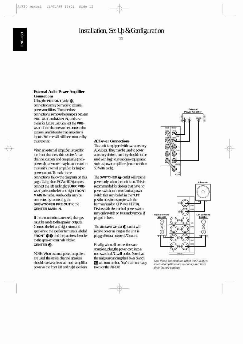
External Audio Power AmplifierConnectionsUsing the PRE OUT jacks ñ,connections may be made to externalpower amplifiers. To make theseconnections, remove the jumpers betweenPRE-OUT and MAIN IN, and savethem for future use. Connect the PRE-OUT of the channels to be connected toexternal amplifiers to that amplifier’sinputs. Volume will still be controlled bythis receiver.
When an external amplifier is used forthe front channels, this receiver’s rearchannel outputs and one passive (non-powered) subwoofer may be connected tothis unit’s internal amplifier for higherpower output. To make theseconnections, follow the diagrams on thispage. Using short RCA to RCA jumpers,connect the left and right SURR PRE-OUT jacks to the left and right FRONTMAIN IN jacks. A subwoofer may beconnected by connecting theSUBWOOFER PRE OUT to theCENTER MAIN IN.
If these connections are used, changesmust be made to the speaker outputs.Connect the left and right surroundspeakers to the speaker terminals labeledFRONT ˙î and the passive subwooferto the speaker terminals labeledCENTER ∆.
NOTE: When external power amplifiersare used, the center channel speakersshould receive at least as much amplifierpower as the front left and right speakers.
AC Power ConnectionsThis unit is equipped with two accessoryAC outlets. They may be used to poweraccessory devices, but they should not beused with high current draw equipmentsuch as power amplifiers (not more than50 Watts each).
The SWITCHED † outlet will receivepower only when the unit is on. This isrecommended for devices that have nopower switch, or a mechanical powerswitch that may be left in the “ON” position (as for example with theharman/kardon CDPlayer HD730).Devices with electronical power switchmay only switch on to standby mode, ifpluged in here.
The UNSWITCHED ü outlet willreceive power as long as the unit isplugged into a powered AC outlet.
Finally, when all connections arecomplete, plug the power cord into anon-switched AC wall outlet. Note thatthe ring surrounding the Power Switch( will turn amber. You’re almost readyto enjoy the AVR80!
CENTER
SURR.
8 OHMS
8 OHMS
FRONT
8 OHMS
R L
SPEAKERS
Subwoofer
Left SurroundSpeaker
Right SurroundSpeaker
+ –
–
MAIN IN PRE OUT
L
FRONT
R
L
SURR.
R
CENTER
SUBWOOFER
L R
ExternalPower Amplifier
CENTER
++ –
Use these connections when the AVR80’sinternal amplifiers are re-configured fromtheir factory settings
AVR80 manual 11/01/98 13:01 Side 12
Remote Control Programming & Operation13
EN
GLIS
H
This product is equipped with a powerfulremote control. As supplied, it will operatethe receiver, as well as most CD playersand tape decks manufactured by HarmanKardon. In addition, it is preprogrammedwith the remote codes to operate VCRs, LDplayers and TV sets that are based on thepopular RC-5 control code system. If yourequipment requires different codes, itmay be programmed to copy the codesfrom most infra red remotes.
Loading BatteriesThe life of the batteries for the remotecontrol is about one year in normaloperation. If the green Sending x
indicator does not flash when remotebuttons are pushed, that is an indicationthat the batteries need to be replaced.Don’t simply through old batteries awaybut recycle only or return them to yourdealer.
To change the batteries:
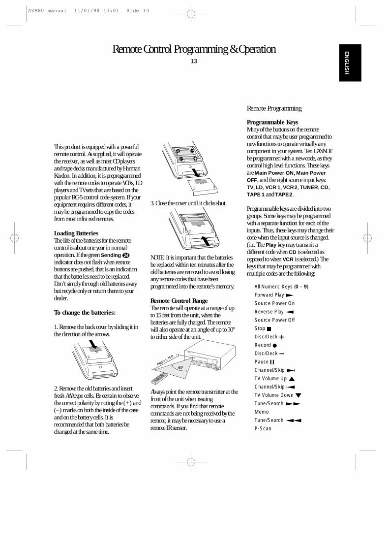
1. Remove the back cover by sliding it inthe direction of the arrows.
2. Remove the old batteries and insertfresh AAA type cells. Be certain to observethe correct polarity by noting the (+) and(–) marks on both the inside of the caseand on the battery cells. It isrecommended that both batteries bechanged at the same time.
3. Close the cover until it clicks shut.
NOTE: It is important that the batteriesbe replaced within ten minutes after theold batteries are removed to avoid losingany remote codes that have beenprogrammed into the remote’s memory.
Remote Control RangeThe remote will operate at a range of upto 15 feet from the unit, when thebatteries are fully charged. The remotewill also operate at an angle of up to 30°to either side of the unit.
Always point the remote transmitter at thefront of the unit when issuingcommands. If you find that remotecommands are not being received by theremote, it may be necessary to use aremote IR sensor.
Remote Programming
Programmable KeysMany of the buttons on the remotecontrol that may be user programmed tonew functions to operate virtually anycomponent in your system. Ten CANNOTbe programmed with a new code, as theycontrol high level functions. These keysare Main Power ON, Main PowerOFF, and the eight source input keys:TV, LD, VCR 1, VCR2, TUNER, CD,TAPE 1 and TAPE2.
Programmable keys are divided into twogroups. Some keys may be programmedwith a separate function for each of theinputs. Thus, these keys may change theircode when the input source is changed.(i.e. The Play key may transmit adifferent code when CD is selected asopposed to when VCR is selected.) Thekeys that may be programmed withmultiple codes are the following:
All Numeric Keys (0 – 9)
Forward Play fl
Source Power On
Reverse Play fi
Source Power Off
Stop Í
Disc/Deck ∏
Record Î
Disc/Deck Â
Pause ±
Channel/Skip ·
TV Volume Up ⁄
Channel/Skip ‡
TV Volume Down ¤
Tune/Search —
Memo
Tune/Search ‚
P-Scan
AVR80 manual 11/01/98 13:01 Side 13
Remote Control Programming & Operation14
EN
GLI
SH
Another group of keys may only beprogrammed with one remote code. Thecode contained in these keys remains thesame regardless of the source selection.
WARNING: These keys transmit codesthat are vital to the operation of theproduct. It is not recommended that theybe programmed with alternative codes, asit may then be impossible to operatecertain functions of the receiver.
THX
Aux
Cursor Up ⁄
Pro Logic
Delay
Cursor Down ¤
Dolby 3 Stereo
Memo
Cursor Right ›
Movie
Screen Display
Cursor Left ‹
Matrix
Panel Display
Select
Hall
Speaker
Main Volume Up ⁄
Stereo
Test Noise
Main Volume Down ¤
Mono
Adjust
Mute
RDS PTY
RDS AF
To program the remote, you need theremote of the device, whose functionsshall be programmed. Note that it is notnecessary to program all keys, only those
that are required to operate the subjectdevice. Keys not programmed will retainthe codes preprogrammed at the factory.
1. Slide Use/Learn a switch at the topleft corner of the remote to the right sothat it is next to Learn.
2. If one of the multi-function buttons isbeing programmed press the sourcebutton (i.e. CD, VCR, etc.) you wish tohave this function associated with. If youare programming a single function key,proceed to the next step.
3. Press the button on the remote that isto be programmed. Note that theLearning y LED will illuminate.
4. Place the remote head to head with theremote control whose function is beinglearned. The two remotes should be nomore than 8 inches apart.
5. Press and hold the button on thetransmitting remote corresponding to thefunction to be memorized until theLearning LED starts to blink. When theLED goes out, release the button on thetransmitting remote. The function codehas been successfully captured.
NOTE: If both LEDs flash during aprogramming operation, it indicates thatthe remote’s memory is full or that theremote codes from the transmittingremote are not compatible with the unit’ssignal format.
6. Continue to program any additionalremote commands required using steps 2through 5. When you have finishedprogramming the remote, slide theUse/Learn switch to the left so that it isin the Use position.
Clearing the Remote MemoryIn normal operation, codes for a newdevice may be programmed “over” thecodes that have been previouslyprogrammed into the remote. It is alsopossible to clear the memory forindividual keys, or for the entire remote.When a memory position is cleared, theremote will return to the original factorypreset command.
To clear the memory for a specificindividual key location, put theUse/Learn switch in the Learnposition. Press the Main Power Off bbutton and the button to be cleared at thesame time. Both the Sending andLearning indicators will lightmomentarily. When the lights go out, thememory has been cleared of the userprogrammed code and returned to thefactory preset. Return the Use/Learna switch to the Use position when youare finished.
To clear the remote’s entire memory and return all keys to their factory presetcommands first put the Use/Learn a
switch in the Learn position. Then pressthe Main Power On button b andconfirm that the Learning indicator yhas illuminated. While continuing topress the Power On button, press andhold the Power Off b button until theLearn indicator goes off for about 3seconds. It will then blink twice. Thenrelease the two buttons. This indicatesthat the memory has been cleared of anyuser programmed commands and thatthe original commands have beenrestored. Slide the Use/Learn switchback to the Use a position to returnthe remote to normal operation.
AVR80 manual 11/01/98 13:01 Side 14
System Configuration15
EN
GLIS
H
When all audio, video and systemconnections have been made, there are afew configuration adjustments to bemade. A few minutes spent to correctlyconfigure and calibrate the unit willgreatly add to your listening experience.
Speaker Selection and PlacementThe placement of speakers in a multichannel home theater system can have anoticeable impact on the quality of soundreproduced. For Home THX operation it isrecommended that the speakers carry thecertification mark of Lucasfilm Ltd.’sHome THX Division. However, withcareful selection and placement, the AVR80 will deliver accurate reproduction withany high quality speakers.
No matter which type or brand ofspeakers are used, the same model orbrand of speaker should be used for thefront left, center and right speakers. Thiscreates a seamless front soundstage, andeliminates the possibility of distractingsonic disturbances that occur when asound moves across mis-matched frontchannel speakers.
For the most accurate and excitingreproduction of bass frequencies aseparate subwoofer should be used. WhenTHX Certified front channel speakers areused a separate subwoofer is mandatory,as THX front and center speakers are notdesigned for extreme low frequencies.
The AVR80 may be used with either conventional (point source) surroundspeakers or with THX Certified diffusesurround speakers. No adjustment isneeded to select the type of surroundspeaker used.
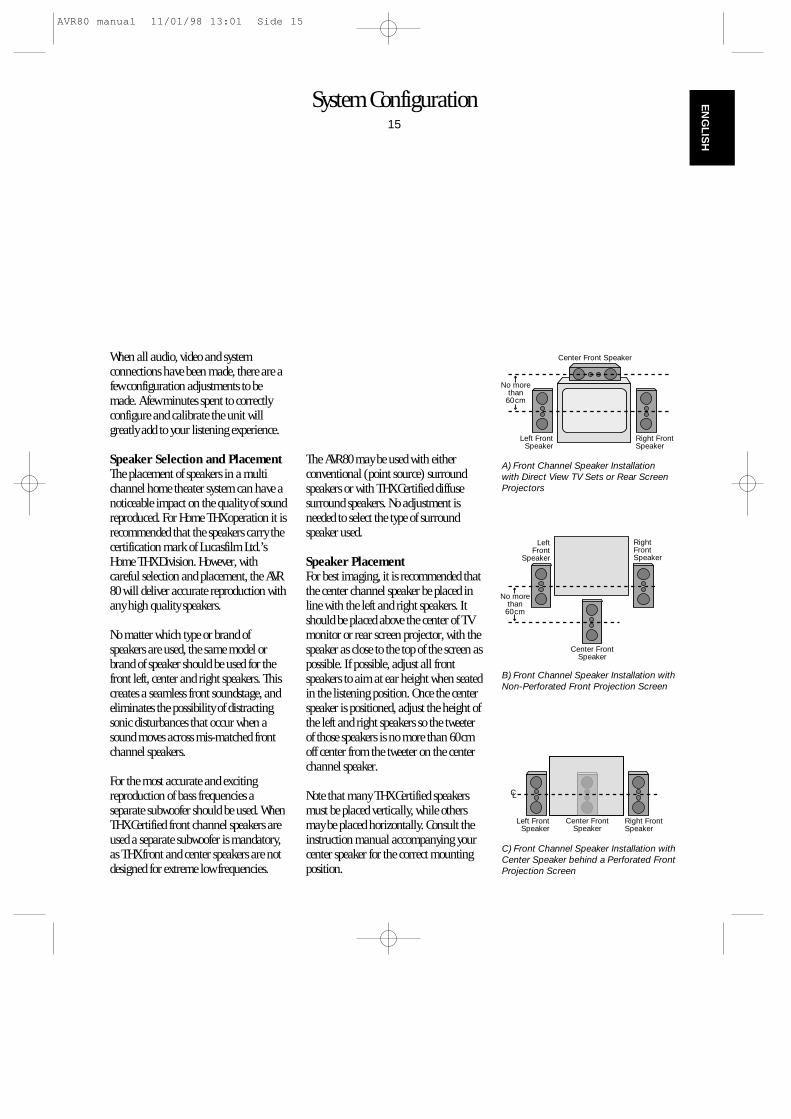
Speaker PlacementFor best imaging, it is recommended thatthe center channel speaker be placed inline with the left and right speakers. Itshould be placed above the center of TVmonitor or rear screen projector, with thespeaker as close to the top of the screen aspossible. If possible, adjust all frontspeakers to aim at ear height when seatedin the listening position. Once the centerspeaker is positioned, adjust the height ofthe left and right speakers so the tweeterof those speakers is no more than 60cmoff center from the tweeter on the centerchannel speaker.
Note that many THX Certified speakersmust be placed vertically, while othersmay be placed horizontally. Consult theinstruction manual accompanying yourcenter speaker for the correct mountingposition.
Right FrontSpeaker
Left FrontSpeaker
No morethan
60cm
Center Front Speaker
Right FrontSpeaker
Left FrontSpeaker
Center FrontSpeaker
RightFrontSpeaker
LeftFront
Speaker
No morethan
60cm
Center FrontSpeaker
A) Front Channel Speaker Installation with Direct View TV Sets or Rear ScreenProjectors
B) Front Channel Speaker Installation withNon-Perforated Front Projection Screen
C) Front Channel Speaker Installation withCenter Speaker behind a Perforated FrontProjection Screen
AVR80 manual 11/01/98 13:01 Side 15
System Configuration16
EN
GLI
SH
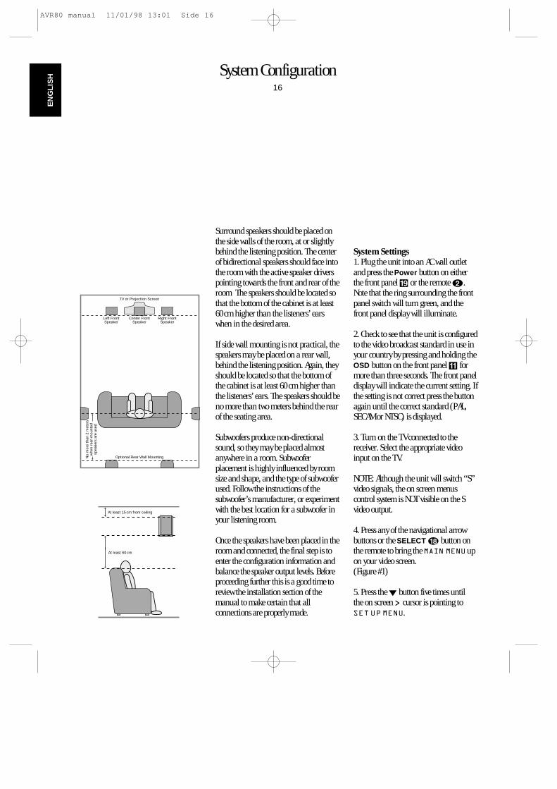
Surround speakers should be placed onthe side walls of the room, at or slightlybehind the listening position. The centerof bidirectional speakers should face intothe room with the active speaker driverspointing towards the front and rear of theroom The speakers should be located sothat the bottom of the cabinet is at least60 cm higher than the listeners’ earswhen in the desired area.
If side wall mounting is not practical, thespeakers may be placed on a rear wall,behind the listening position. Again, theyshould be located so that the bottom ofthe cabinet is at least 60 cm higher thanthe listeners’ ears. The speakers should beno more than two meters behind the rearof the seating area.
Subwoofers produce non-directionalsound, so they may be placed almostanywhere in a room. Subwooferplacement is highly influenced by roomsize and shape, and the type of subwooferused. Follow the instructions of thesubwoofer’s manufacturer, or experimentwith the best location for a subwoofer inyour listening room.
Once the speakers have been placed in theroom and connected, the final step is toenter the configuration information andbalance the speaker output levels. Beforeproceeding further this is a good time toreview the installation section of themanual to make certain that allconnections are properly made.
Center FrontSpeaker
Optional Rear Wall Mounting
TV or Projection Screen
Right FrontSpeaker
Left FrontSpeaker
No
mor
e th
an 2
met
ers
whe
n re
ar-m
ount
edsp
eake
rs a
re u
sed
At least 60 cm
At least 15 cm from ceiling
System Settings1. Plug the unit into an AC wall outletand press the Power button on eitherthe front panel ( or the remote b.Note that the ring surrounding the frontpanel switch will turn green, and thefront panel display will illuminate.
2. Check to see that the unit is configuredto the video broadcast standard in use inyour country by pressing and holding theOSD button on the front panel ! formore than three seconds. The front paneldisplay will indicate the current setting. Ifthe setting is not correct press the buttonagain until the correct standard (PAL,SECAM or NTSC) is displayed.
3. Turn on the TV connected to thereceiver. Select the appropriate videoinput on the TV.
NOTE: Although the unit will switch “S”video signals, the on screen menuscontrol system is NOT visible on the Svideo output.
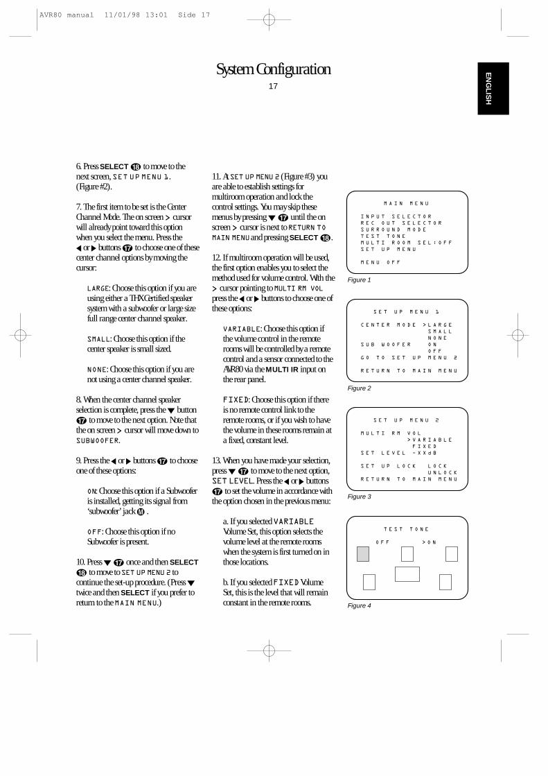
4. Press any of the navigational arrowbuttons or the SELECT r button onthe remote to bring the MAIN MENU upon your video screen. (Figure #1)
5. Press the ¤ button five times until the on screen > cursor is pointing toSET UP MENU.
AVR80 manual 11/01/98 13:01 Side 16
System Configuration17
EN
GLIS
H
6. Press SELECT r to move to thenext screen, SET UP MENU 1. (Figure #2).
7. The first item to be set is the CenterChannel Mode. The on screen > cursorwill already point toward this optionwhen you select the menu. Press the ‹ or › buttons q to choose one of thesecenter channel options by moving thecursor:
LARGE: Choose this option if you areusing either a THX Certified speakersystem with a subwoofer or large sizefull range center channel speaker.
SMALL: Choose this option if thecenter speaker is small sized.
NONE: Choose this option if you arenot using a center channel speaker.
8. When the center channel speakerselection is complete, press the ¤ buttonq to move to the next option. Note thatthe on screen > cursor will move down toSUBWOOFER.
9. Press the ‹ or › buttons q to chooseone of these options:
ON: Choose this option if a Subwooferis installed, getting its signal from‘subwoofer’ jack µ .
OFF: Choose this option if noSubwoofer is present.
10. Press ¤ q once and then SELECTr to move to SET UP MENU 2 tocontinue the set-up procedure. (Press ¤twice and then SELECT if you prefer toreturn to the MAIN MENU.)
11. At SET UP MENU 2 (Figure #3) youare able to establish settings formultiroom operation and lock thecontrol settings. You may skip thesemenus by pressing ¤ q until the onscreen > cursor is next to RETURN TOMAIN MENUand pressing SELECT r.
12. If multiroom operation will be used,the first option enables you to select themethod used for volume control. With the> cursor pointing to MULTI RM VOLpress the ‹ or › buttons to choose one ofthese options:
VARIABLE: Choose this option ifthe volume control in the remoterooms will be controlled by a remotecontrol and a sensor connected to theAVR80 via the MULTI IR input onthe rear panel.
FIXED: Choose this option if thereis no remote control link to theremote rooms, or if you wish to havethe volume in these rooms remain ata fixed, constant level.
13. When you have made your selection,press ¤ q to move to the next option,SET LEVEL. Press the ‹ or › buttonsq to set the volume in accordance withthe option chosen in the previous menu:
a. If you selected VARIABLEVolume Set, this option selects thevolume level at the remote roomswhen the system is first turned on inthose locations.
b. If you selected FIXEDVolumeSet, this is the level that will remainconstant in the remote rooms.
I N P U T S E L E C T O R
R E C O U T S E L E C T O R
S U R R O U N D M O D E
T E S T T O N E
M U L T I R O O M S E L : O F F
S E T U P M E N U
M E N U O F F
M A I N M E N U
Figure 1
C E N T E R M O D E > L A R G E
S M A L L
N O N E
S U B W O O F E R O N
O F F
G O T O S E T U P M E N U 2
R E T U R N T O M A I N M E N U
S E T U P M E N U 1
Figure 2
M U L T I R M V O L
> V A R I A B L E
F I X E D
S E T L E V E L Ð X X d B
S E T U P L O C K L O C K
U N L O C K
R E T U R N T O M A I N M E N U
S E T U P M E N U 2
Figure 3
O F F > O N
T E S T T O N E
Figure 4
AVR80 manual 11/01/98 13:01 Side 17
System Configuration18
EN
GLI
SH
14. When you have made a volumeselection, press ¤ q to move to thenext option. Note that the > cursorshould point to SET UP LOCK.
15. This option enables you to lock thesettings at the SET UP MENU 1. Thismakes it difficult for someone toinadvertently change the settings bycausing the word LOCK to appear at thetop of SET UP MENU 1. Before anyfurther changes are made, the user mustfirst go to SET UP MENU 2 andunlock the system. Press the ‹ or ›buttons q to choose one of theseoptions:
LOCK: Choose this option to lock thesettings as described above.
UNLOCK: Choose this option tounlock the settings and enable themto be changed without going to thismenu.
16. When you have made your choice,press ¤ q and then SELECT r toreturn to the main menu. At this pointthe output levels for all channels will beset to a reference so that the sound level isthe same from each speaker. Thiscompensates for the differences betweenthe speakers used and the distance eachspeaker is from your listening position.
At this point you may wish to adjust therear channel delay time. See the AdvancedFeatures section later in this manual forinformation on delay settings.
NOTE: Before setting the output levels itis critical that the front panel bass ¯and treble controls ˘ be set to theircenter, or “12 o’clock” position. Thisensures accurate results.
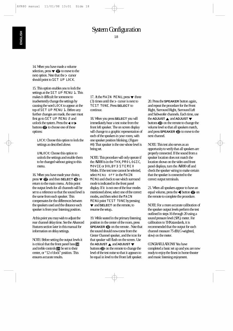
17. At the MAIN MENU, press ¤ three(3) times until the > cursor is next toTEST TONE. Press SELECT tocontinue.
18. When you press SELECT you willimmediately hear a test noise from thefront left speaker. The on screen displaywill change to a graphic representation ofeach of the speakers in your room, withone speaker position blinking. (Figure#4) That speaker is the one whose level isbeing set.
NOTE: This procedure will only operate ifthe AVR80 is in the THX, PROLOGIC,MOVIEor DOLBY3 STEREOModes. If the test tone cannot be selected,select MENU OFF in the MAINMENUand check to see which surroundmode is indicated in the front paneldisplay. If it is not one of the four modesmentioned above, select one of the correctmodes, and then select the MAINMENUpoint TEST TONEby pressing¤ and SELECT on the remote, toresume the setup..
19. While seated in the primary listeningposition in the center of the room, pressSPEAKER v on the remote . Note thatthe sound should now come from theCenter Channel speaker, and the icon forthat speaker will flash on the screen. Usethe ADJUST ⁄ and ADJUST ¤
buttons w on the remote to change thelevel of the test noise so that it appears tobe equal in level to the Front Left speaker.
20. Press the SPEAKER button again,and repeat the procedure for the FrontRight, Surround Right, Surround Leftand Subwoofer channels. Each time, usethe ADJUST ⁄ and ADJUST ¤
buttons w on the remote to change thevolume level so that all speakers match,and press SPEAKER v to move to thenext channel.
NOTE: This test also serves as anopportunity to verify that all speakers are properly connected. If the sound from aspeaker location does not match thelocation shown on the video and frontpanel displays, turn the AVR80 off andcheck the speaker wiring to make certainthat the speaker is connected to the correct output terminals.
21. When all speakers appear to have anequal volume, press the ‹ button q onthe remote to complete the procedure.
NOTE: For a more accurate calibration ofthe speaker output levels perform the testoutlined in steps 16 through 20 using asound pressure level (SPL) meter. Forcalibration to THX standards, it isrecommended that the output for eachchannel measure 75 dB (C-weighted,slow) on the meter.
CONGRATULATIONS! You havecompleted a basic set up and you are nowready to enjoy the finest in home theaterand music listening enjoyment.
AVR80 manual 11/01/98 13:01 Side 18
Basic Operation19
EN
GLIS
H
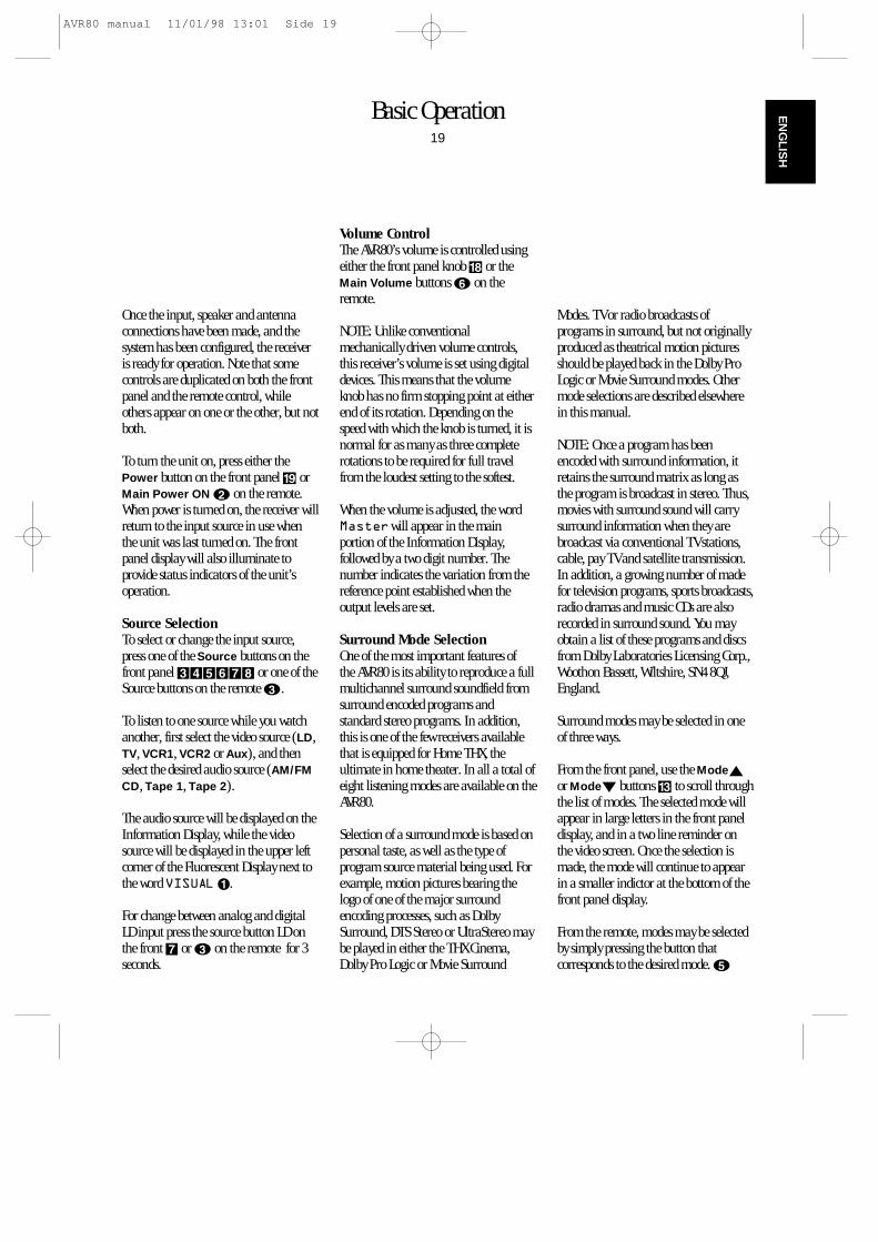
Once the input, speaker and antennaconnections have been made, and thesystem has been configured, the receiveris ready for operation. Note that somecontrols are duplicated on both the frontpanel and the remote control, whileothers appear on one or the other, but notboth.
To turn the unit on, press either thePower button on the front panel ( orMain Power ON b on the remote.When power is turned on, the receiver willreturn to the input source in use whenthe unit was last turned on. The frontpanel display will also illuminate toprovide status indicators of the unit’soperation.
Source SelectionTo select or change the input source,press one of the Source buttons on thefront panel 345678 or one of theSource buttons on the remote c.
To listen to one source while you watchanother, first select the video source (LD,TV, VCR1, VCR2 or Aux), and thenselect the desired audio source (AM/FMCD, Tape 1, Tape 2).
The audio source will be displayed on theInformation Display, while the videosource will be displayed in the upper leftcorner of the Fluorescent Display next tothe word VISUAL¡.
For change between analog and digitalLD input press the source button LD onthe front 7 or c on the remote for 3seconds.
Volume ControlThe AVR80’s volume is controlled usingeither the front panel knob * or theMain Volume buttons f on theremote.
NOTE: Unlike conventionalmechanically driven volume controls,this receiver’s volume is set using digitaldevices. This means that the volumeknob has no firm stopping point at eitherend of its rotation. Depending on thespeed with which the knob is turned, it isnormal for as many as three completerotations to be required for full travelfrom the loudest setting to the softest.
When the volume is adjusted, the wordMasterwill appear in the mainportion of the Information Display,followed by a two digit number. Thenumber indicates the variation from thereference point established when theoutput levels are set.
Surround Mode SelectionOne of the most important features of the AVR80 is its ability to reproduce a fullmultichannel surround soundfield fromsurround encoded programs andstandard stereo programs. In addition,this is one of the few receivers availablethat is equipped for Home THX, theultimate in home theater. In all a total ofeight listening modes are available on theAVR80.
Selection of a surround mode is based onpersonal taste, as well as the type ofprogram source material being used. Forexample, motion pictures bearing thelogo of one of the major surroundencoding processes, such as DolbySurround, DTS Stereo or UltraStereo maybe played in either the THX Cinema,Dolby Pro Logic or Movie Surround
Modes. TV or radio broadcasts ofprograms in surround, but not originallyproduced as theatrical motion picturesshould be played back in the Dolby ProLogic or Movie Surround modes. Othermode selections are described elsewherein this manual.
NOTE: Once a program has beenencoded with surround information, itretains the surround matrix as long asthe program is broadcast in stereo. Thus,movies with surround sound will carrysurround information when they arebroadcast via conventional TV stations,cable, pay TV and satellite transmission.In addition, a growing number of madefor television programs, sports broadcasts,radio dramas and music CDs are alsorecorded in surround sound. You mayobtain a list of these programs and discsfrom Dolby Laboratories Licensing Corp.,Woothon Bassett, Wiltshire, SN4 8QJ,England.
Surround modes may be selected in oneof three ways.
From the front panel, use the Mode⁄or Mode¤ buttons # to scroll throughthe list of modes. The selected mode willappear in large letters in the front paneldisplay, and in a two line reminder onthe video screen. Once the selection ismade, the mode will continue to appearin a smaller indictor at the bottom of thefront panel display.
From the remote, modes may be selectedby simply pressing the button thatcorresponds to the desired mode. e
AVR80 manual 11/01/98 13:01 Side 19
Basic Operation20
EN
GLI
SH
Modes may also be selected using the onscreen display. Press SELECT r onthe remote to display the MAIN MENU.Then press ¤ q twice so that the onscreen cursor is next to SURROUNDMODE. Press SELECT r again tomove to the next menu.
At the SURROUND MODE MENU,press the ‹ or › buttons r until thedesired mode name appears on thescreen. Press ¤ twice until the > cursoris next to RETURN TO MAIN MENUand press SELECT. At the main menuselect MENU OFFand press SELECTto exit the menus.
A different mode may be selected foraudio and video sources. Once a modehas been selected, it will be attached tothose sources in memory. Thus, you mayselect THX CINEMAas the mode forvideo and HALL SURROUND foraudio. After the initial selections aremade, the unit will automatically returnto your preferred mode for each type ofinput whenever it is chosen.
TV Auto FunctionWith the increasing sophistication oftoday’s home entertainment systems, itoften takes numerous remote controls toturn a system on. This receiver’s unique“TV Auto” feature simplifies that task andgreatly reduces the actions needed tobring your entire system to life.
If a video feed is connected to the TVVIDEO IN jack N during theinstallation, that signal is used to triggersystem turn on. Even when the receiver isturned off, the presence of an video signalat the TV VIDEO jack will automaticallycause the receiver to turn on. As long asthe signal is present, the receiver willremain on. When the TV or other sourceis turned off, the receiver willautomatically return to a standby (“off”)mode within five minutes.
Note that if the receiver is turned onautomatically by this function, it willremain on if another source issubsequently selected. In that case, thereceiver needs to be turned off manuallyeven if the TV source is turned off.
Tuner OperationThe FM/AM tuner is extremely flexible,and offers a number of options. Thefollowing instructions will enable you totake advantage of the tuner’s manyfeatures.
To select tuner operation, press theAM/FM button 3 on the front panel, orthe remote c. Press the button again toselect the desired frequency band ifrequired.
Manual up/down tuning is accessible by pressing the TUNE button ^ eitherup ⁄ or down ¤ or the Tune/Search‚ and Tune/Search —j buttons on the remote. Pressing thesebuttons once increases or decreases thestation frequency by one step. Holding thebuttons down quickly scans for the nextstation. Holding the tune buttons for afew seconds and then releasing themautomatically will set the tuner to thenext station with an acceptable signal.
When manually tuning stations, observethe SIGNAL LEVEL indicator fl andthe TUNED∞ indicators. The morebars visible on the SIGNAL LEVELindicator, the stronger the signal and thebetter the station will sound. A station isproperly tuned when the TUNEDindicator is illuminated.
Tuner ModePressing the FM Mode button Ù on thefront panel selects how a station will bereceived. When the button is pressed sothat the AUTO¢ indicator is lit,stations broadcasting in stereo will bereceived in stereo. You may note stereobroadcasts by observing that theSTEREO§ indicator will illuminate.When the FM Mode button Ù ispressed until the AUTO¢ light goesout, all stations will be received in amonaural mode regardless of the methodof transmission.
NOTE: When a station is broadcasting instereo, but has a weak signal level, thereproduction may not be acceptable. Inthis case, select the Auto Off mode, asmonaural reception is less susceptible tonoise in weak reception areas.
Tuner PresetsThere are thirty preset positions that maybe used to store your favorite stations inany order. These may be used tomemorize both the station’s frequency,reception mode and a name. Stationsmay be preset automatically ormanually, and then recalled in a varietyof ways.
AVR80 manual 11/01/98 13:01 Side 20
Basic Operation21
EN
GLIS
H
Automatic Station Preset SelectionThis process automatically scans the AMand FM bands and enters all stations withproper signal strength into the memory.To automatically preset the tuner’smemory, follow these steps:
1. Select the tuner as the unit’s input bypressing the AM/FM button 3c.
2. Using the TUNE ^j buttons, selectthe first station you wish to preset at thelow end of the AM or FM band.
3. Start the automatic tuning preset bysimultaneously pressing MEMO andTUNE ⁄ on the front panel Ú^. Thestation tuned in step #2 will be enteredinto the tuner’s memory as CH1. TheMEMO£ and AUTO MEMOfi
indicators will flash. The display willshow increasing frequencies to indicatethat the auto scan is in progress.
4. Each time the tuner finds a station thescanning will pause and the station willbe played for five seconds. During thistime you have the following options:
a. To enter the station in the nextopen memory position, no action isneeded. After five seconds the tunerwill enter the station and the presetnumber will be visible at the far leftside of the main information display.
b. The frequency band may bechanged by pressing the FM/AMbutton 3c.
c. If the tuner is scanning FMstations, the MODE may be changedfrom AUTO to mono by pressing theFM MODE button Ù.
d. If you do not wish to enter thecurrent station into the presetmemory, press the TUNE ⁄ button^j on the front panel or remote.
5. After the desired action is completed, orfive seconds elapse, the tuner scan willcontinue. The operation will stopautomatically when all 30 presetpositions are filled or when bothfrequency bands have been completelytuned, whichever comes first. To stop theautomatic preset process at any timepress the CLEAR button Û or any inputselection button.
Manual Tuner PresetStations may be manually entered intothe tuner’s memory in any order. Manualentry is performed from the remotecontrol only.
1. Tune to the desired station as outlinedin Tuner Operation Section.
2. Press the MEMO button Úo andnote that the MEMO indicator £ willflash.
3. While the indicator is flashing for thenext 5 seconds, enter a number from 1 to30 using the number buttons on theremote m. Any number may be used,but if another station has already beenprogrammed into the location numberselected, the previous setting will be lost.
a. To enter a single digit memorylocation, press 0 before the number,or enter the number and wait a fewseconds.
b. If an invalid number (other than1–30) is entered in error, the displaywill flash to alert you that the entry isinvalid and it will return to theprevious frequency display.
4. When the preset memory has beenproperly programmed the MEMOindicator £ will stop blinking.
Station Name PresetIn addition to identifying stations by theirbroadcast frequency or by the RDS systemeach preset station manually may beassigned a name using alphanumericcharacters. This enables you to identify astation by its call letters, program format,or any other five character phrase.
To enter a station name, first preset allstations you wish to program into thetuner’s memory. Then, follow these steps:
1. Tune to the desired preset station.
2. Press the MEMO button Ú on thefront panel or o on the remote formore than three seconds.
3. Note that a character on the left side ofthe main information display will start toblink.
4. Enter the first character of the nameusing either the front panel TUNE ⁄ or¤ buttons ^ or the alphanumericbuttons m on the remote.
AVR80 manual 11/01/98 13:01 Side 21
Basic Operation22
EN
GLI
SH
A. To use the front panel buttons simplypress and hold TUNE ⁄ ^ buttonuntil the desired letter or numberappears. Note that the upper casealphabet will appear, followed by thenumbers 1 through 0 , and then a Ðindicating a blank space. Tapping thebutton will advance the display onecharacter at a time; holding it down willmove the display quickly. If you pass bythe desired character, use the TUNE ¤
^ to move the display in reverse.
After entering the first character, pressMEMO Ú to move to the next positionand note that the next digit will blink.Use the same procedure outlined above toenter a character.
When you have entered a digit or “blank”in all five spaces, press MEMO Ú formore than 1 second to confirm the entry
B. To use the remote for character entry,press the button corresponding to thedesired letter or number. Press it once toenter the first printed letter, twice for thesecond, three times for the third and fourtimes for the number. Press the “9”button to enter a blank space. (Forexample, press the “ABC” button onceto enter an “A”, three times for a “C”and four times to enter a “1”.)
Use the MEMO button o to move tothe next digit position. When all fivespaces have been filled, press MEMOagain for more than 1 second to confirmthe entry.
Once a station name has been attached toa preset position, the station’s frequencywill appear briefly when the unit is tunedto that station. After a few seconds thepreset name will appear in the display.
Tuning Preset StationsStations preset into the tuner’s memorymay be recalled in a number of ways.
1. To recall a station directly enter anumber from 1 to 30 using the numberbuttons on the remote s m .
a. To enter a single digit memorylocation, press 0 before the number,or enter the number and wait a fewseconds.
b. If an invalid number (other than1–30) is entered in error, thatnumber will flash to alert you thatthe entry is invalid and the displaywill return to the previous frequencydisplay.
2. To scan through the list of presetstations, press the P-SET⁄ or P-SET¤ on the front panel $ or theCHANNEL buttons ‡ · remote k.Press once to move up or down throughthe memory presets one by one, or pressand hold the button to quickly scanthrough the list of stations.
3. To automatically review each stationin the memory, press the P-SCANbutton n%. Note that the P-SCANindicator › will blink.
The tuner will move up through the listof stations, pausing to play each for fiveseconds. Note that preset numbers whereno station has been programmed will beskipped.
When the desired station is reached pressP-SCAN % or CLEAR Û.
Clearing Preset Stations Once stations are programmed into thepreset memories, it is possible to removethem individually or as a group.
To remove a single station from thememory:
1. Recall the station by pressing thebuttons on the remote corresponding tothe station’s memory location.
2. Press the MEMO button Ú or oand observe that the MEMO indicator £will blink.
3. While the indicator is blinking, pressthe CLEAR button Û -not the CLEARbutton on the remote within five seconds.The word CLEARwill show briefly toconfirm that the memory position hasbeen cleared.
To clear all memory locations, the volume level and surround mode memories:
1. Press the MEMO button Úo andthe CLEAR button Ûm at the sametime for some seconds, until CLEARMEMOappears on the display.
NOTE: When a complete memory clear isperformed the AVR80 will turn off as partof the process. After clearing the memoryit is necessary to reset all stations and setup parameters.
AVR80 manual 11/01/98 13:01 Side 22
Basic Operation23
EN
GLIS
H
RDS Operation
Now in use in many countries, RDS(Radio Data System) is a means oftransmitting station call signs or networkidentification, a description of thestation’s programming, indication ofnational, regional or local programmesand others using hidden space in the FMsignal. Your new receiver is equipped withRDS to assist in the selection of FMstations using station and networknames, rather than broadcastfrequencies. Additional RDS functionsinclude the ability to search forprogramme types or to find stations witha specific programme type that have astronger signal.
Programme Service DisplayWhen a receiver is tuned to an FM stationthat is transmitting RDS data, the frontpanel information display willautomatically show the programmeservice, network or station name in placeof the typical display of the station’sbroadcast frequency. To display thefrequency, press the front panel RDSDISP button ı.
Programme Type (PTY) DisplayThe RDS system categorizes programmesaccording to their genre into differentprogramme type (PTY) groups. Todisplay the programme type informationof the current station, simply press theRDS/PTY button on either the remotecontrol or the front panel ˜z.
Please note that many Stations don´tbroadcast PTY codes yet. Then NONE isindicated.
PTY Auto SearchYour receiver is equipped toautomatically search for stationstransmitting any of the fifteen differentprogramme types. To search for a PTY,follow these steps:
1. Press the RDS/PTY button on eitherthe front panel or the remote. The currentstation’s PTY will be displayed, or thecurrently selected PTY group will bedisplayed if no station or RDS data ispresent.
2. To change to a new PTY type, press theRDS/PTY button ˜z again until thedesired PTY is shown in the display.
a. When PTY selection is made using theRDS/PTY button only, the selectionuses the PTY Group shown in Table 1.
b. To select a specific PTY type directly,use the numeric buttons on the remotecontrol m to select the programmetype corresponding to the numberedchoices in Table 1.
3. Once the desired PTY group or type hasbeen selected, press the Tune Up/Downbuttons on the front panel or remotecontrol ^j while the PTY indicationis blinking (within 5 seconds). The PTYAuto search will start, and the tuner willstop at the next station broadcasting RDSPTY information corresponding to theselected choice.
4. To advance to the next RDS stationwith the desired PTY, press the TuneUp/Down button again within 5 seconds.
AF Auto SearchA unique feature of the RDS system is itsability to find a station with identicalprogramming automatically. Thisfeature is particularly useful whenlistening to a national radio stationwhere the same program is broadcastfrom a number of transmitters.
To search for Alternate Frequencies follow these steps:
1. Tune the receiver to the desired stationusing the Tune Up/Down buttons^j.
2. Press the RDS/AF button on the frontpanel or remote control ˆ` twicewithin 1 second.
3. The tuner will automatically search forstations broadcasting the same program.When these stations are received, thefront panel display will indicate AF-1 . Ifthe RDS/AF button is pressed again, thedisplay will indicate the next identicallyprogrammed station by AF-2 .
4. Press the RDS/AF button repeatedlyuntil a station is indicated that has thedesired high enough signal strength.When the display indicates AF-0 thetuner has returned to the original station.
NOTE: If the front panel display indicatesNOAFafter the RDS/AF button ispressed once, no alternate stations withthe same program actually are avilable(not yet searched). In this case pressRDS/AF twice within 1 second to startthe AF search.
AVR80 manual 11/01/98 13:01 Side 23
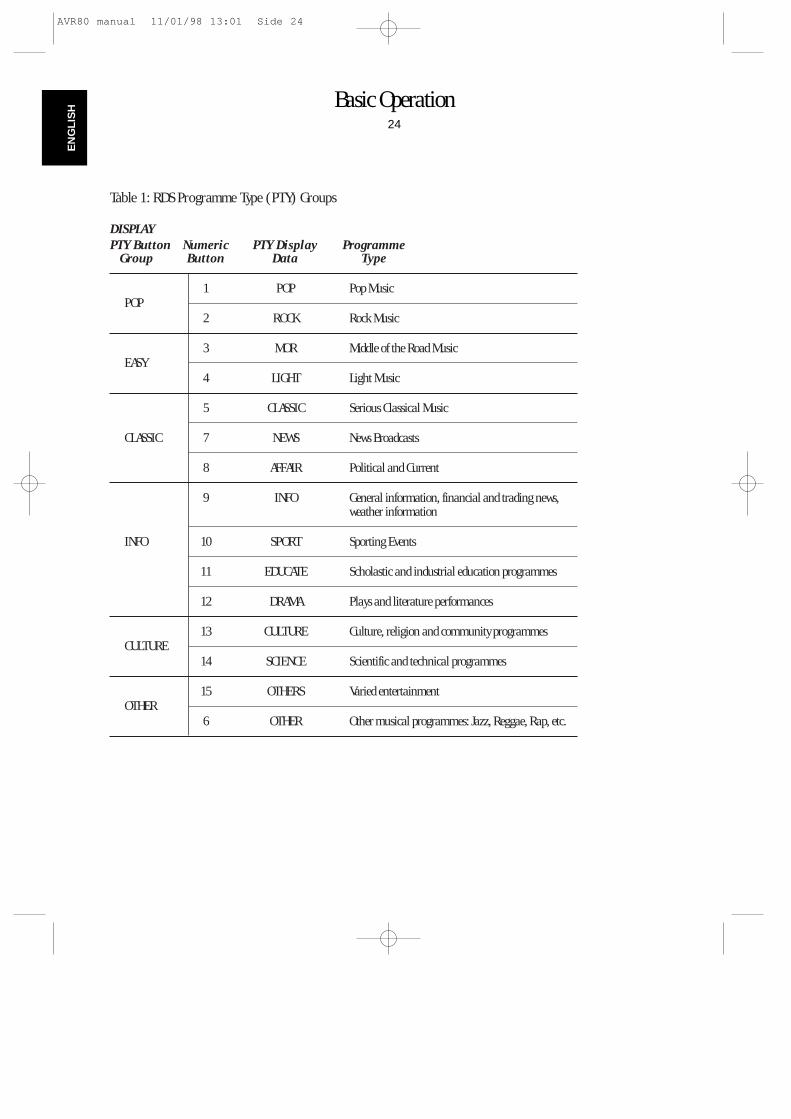
Basic Operation24
EN
GLI
SH
DISPLAYPTY Button Numeric PTY Display Programme
Group Button Data Type
POP1 POP Pop Music
2 ROCK Rock Music
EASY3 MOR Middle of the Road Music
4 LIGHT Light Music
5 CLASSIC Serious Classical Music
CLASSIC 7 NEWS News Broadcasts
8 AFFAIR Political and Current
9 INFO General information, financial and trading news, weather information
INFO 10 SPORT Sporting Events
11 EDUCATE Scholastic and industrial education programmes
12 DRAMA Plays and literature performances
CULTURE13 CULTURE Culture, religion and community programmes
14 SCIENCE Scientific and technical programmes
OTHER15 OTHERS Varied entertainment
6 OTHER Other musical programmes: Jazz, Reggae, Rap, etc.
Table 1: RDS Programme Type (PTY) Groups
AVR80 manual 11/01/98 13:01 Side 24
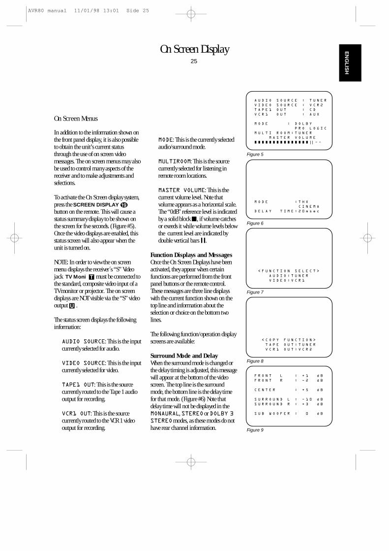
On Screen Display25
EN
GLIS
H
On Screen Menus
In addition to the information shown onthe front panel display, it is also possibleto obtain the unit’s current statusthrough the use of on screen videomessages. The on screen menus may alsobe used to control many aspects of thereceiver and to make adjustments andselections.
To activate the On Screen display system,press the SCREEN DISPLAY s
button on the remote. This will cause astatus summary display to be shown onthe screen for five seconds. (Figure #5).Once the video displays are enabled, thisstatus screen will also appear when theunit is turned on.
NOTE: In order to view the on screenmenu displays the receiver´s “S” Videojack TV Moni T must be connected tothe standard, composite video input of aTV monitor or projector. The on screendisplays are NOT visible via the “S” videooutput U .
The status screen displays the followinginformation:
AUDIO SOURCE: This is the inputcurrently selected for audio.
VIDEO SOURCE: This is the inputcurrently selected for video.
TAPE1 OUT: This is the sourcecurrently routed to the Tape 1 audiooutput for recording.
VCR1 OUT: This is the sourcecurrently routed to the VCR 1 videooutput for recording.
MODE: This is the currently selectedaudio/surround mode.
MULTIROOM: This is the sourcecurrently selected for listening inremote room locations.
MASTER VOLUME: This is thecurrent volume level. Note thatvolume appears as a horizontal scale.The “0dB” reference level is indicatedby a solid block Í, if volume catchesor exeeds it while volume levels belowthe current level are indicated bydouble vertical bars ±.
Function Displays and MessagesOnce the On Screen Displays have beenactivated, they appear when certainfunctions are performed from the frontpanel buttons or the remote control.These messages are three line displayswith the current function shown on thetop line and information about theselection or choice on the bottom twolines.
The following function/operation displayscreens are available:
Surround Mode and DelayWhen the surround mode is changed orthe delay timing is adjusted, this messagewill appear at the bottom of the videoscreen. The top line is the surroundmode, the bottom line is the delay timefor that mode. (Figure #6) Note thatdelay time will not be displayed in theMONAURAL, STEREOor DOLBY 3STEREOmodes, as these modes do nothave rear channel information.
A U D I O S O U R C E : T U N E R
V I D E O S O U R C E : V C R 2
T A P E 1 O U T : C D
V C R 1 O U T : A U X
M O D E : D O L B Y
P R O L O G I C
M U L T I R O O M : T U N E R
M A S T E R V O L U M E
Ù Ù Ù Ù Ù Ù Ù Ù Ù Ù Ù Ù Ù Ù Ù || Ð Ð
Figure 5
M O D E : T H X
C I N E M A
D E L A Y T I M E : 2 0 m s e c
Figure 6
< C O P Y F U N C T I O N >
T A P E O U T : T U N E R
V C R 1 O U T : V C R 2
Figure 8
< F U N C T I O N S E L E C T >
A U D I O : T U N E R
V I D E O : V C R 1
Figure 7
F R O N T L : + 1 d B
F R O N T R : Ð 2 d B
C E N T E R : + 5 d B
S U R R O U N D L : Ð 1 0 d B
S U R R O U N D R : + 3 d B
S U B W O O F E R : 0 d B
Figure 9
AVR80 manual 11/01/98 13:01 Side 25
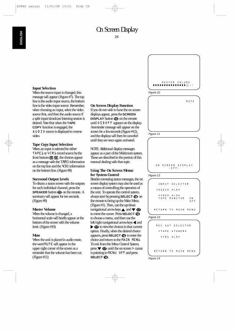
On Screen Display26
EN
GLI
SH
Input SelectionWhen the source input is changed, thismessage will appear (Figure #7). The topline is the audio input source, the bottomline is the video input source. Remember,when choosing an input, select the videosource first, and then the audio source ifa split input/simulcast listening session isdesired. Note that when the TAPECOPY function is engaged, theAUDIO source is displayed in reversevideo.
Tape Copy Input SelectionWhen an input is selected for eitherTAPE1or VCR1 record source by thefront buttons Ò, the choices appearas a message with the TAPE1 informationon the top line and the VCR1 informationon the bottom line. (Figure #8)
Surround Output LevelsTo obtain a status screen with the outputsfor each individual channel, press theSPEAKER button v on the remote. Asummary will appear for ten seconds.(Figure #9)
Master VolumeWhen the volume is changed, ahorizontal scale will briefly appear at thebottom of the screen with the volumelevel. (Figure #10)
MuteWhen the unit is placed in audio mute,the word MUTEwill appear in the upper right corner of the screen as areminder that the volume has been cut.(Figure #11)
On Screen Display FunctionIf you do not wish to have the on screendisplays appear, press the SCREENDISPLAY button s on the remoteuntil OSDOFF appears on the display.A reminder message will appear on thescreen for a few seconds (Figure #12),and the displays will then be canceleduntil they are once again activated.
NOTE: Additional display messagesappear as a part of the Multiroom system.These are described in the portion of thismanual dealing with that topic.
Using The On Screen Menus for System ControlBesides conveying status messages, the onscreen display system may also be used asa means of controlling the operation ofthe unit. To operate the control system,always start by pressing SELECT r onthe remote to bring up the Main Menu.(Figure #1). Then, use the up/downnavigational arrow keys ⁄ and ¤ q
to move the cursor. Press SELECT r
to choose a menu, and then use theleft/right navigational arrow keys ‹ and›q to view the choices in that currentoption. Finally, when the desired choiceappears, press SELECT r to enter thechoice and return to the MAIN MENU.To exit from the Menu Control System,press ¤ q until the on screen > cursoris pointing to MENU OFFand pressSELECT r.
M A S T E R V O L U M E
Ù Ù Ù Ù Ù Ù Ù Ù Ù Ù Ù Ù Ù Ù Ù || Ð Ð
Figure 10
M U T E
Figure 11
O N S C R E E N D I S P L A Y
Ð O F F Ð
Figure 12
> T A P E * T U N E R *
V C R 1 * L D *
R E T U R N T O M A I N M E N U
R E C O U T S E L E C T O R
Figure 14
> A U D I O * L D *
V I D E O * L D *
T A P E M O N I T O R O N
O F F
R E T U R N T O M A I N M E N U
I N P U T S E L E C T O R
Figure 13
AVR80 manual 11/01/98 13:01 Side 26
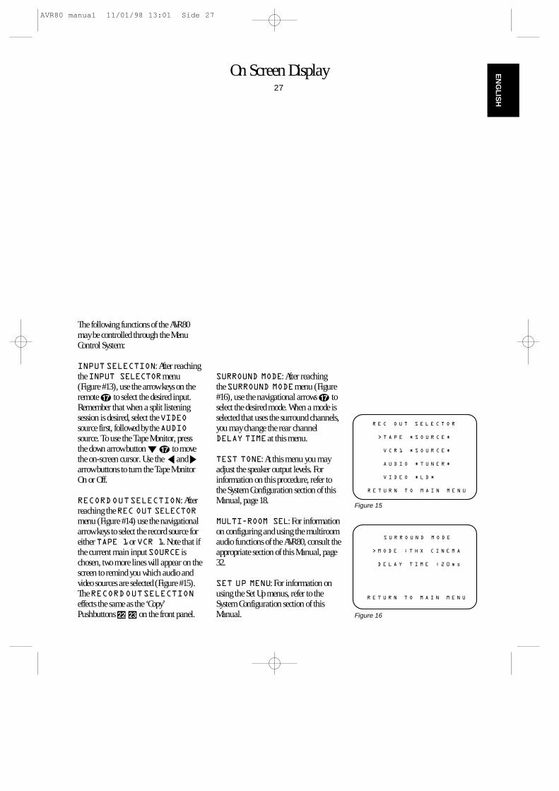
On Screen Display27
EN
GLIS
H
The following functions of the AVR80may be controlled through the MenuControl System:
INPUT SELECTION: After reachingthe INPUT SELECTORmenu(Figure #13), use the arrow keys on theremote q to select the desired input.Remember that when a split listeningsession is desired, select the VIDEOsource first, followed by the AUDIOsource. To use the Tape Monitor, pressthe down arrow button ¤ q to movethe on-screen cursor. Use the ‹ and ›arrow buttons to turn the Tape MonitorOn or Off.
RECORDOUTSELECTION: Afterreaching the REC OUT SELECTORmenu (Figure #14) use the navigationalarrow keys to select the record source foreither TAPE 1or VCR 1. Note that ifthe current main input SOURCE ischosen, two more lines will appear on thescreen to remind you which audio andvideo sources are selected (Figure #15).The RECORDOUTSELECTIONeffects the same as the ‘Copy’Pushbuttons Ò on the front panel.
SURROUND MODE: After reaching the SURROUND MODEmenu (Figure#16), use the navigational arrows q toselect the desired mode. When a mode isselected that uses the surround channels,you may change the rear channelDELAY TIMEat this menu.
TEST TONE: At this menu you mayadjust the speaker output levels. Forinformation on this procedure, refer tothe System Configuration section of thisManual, page 18.
MULTI-ROOM SEL: For informationon configuring and using the multiroomaudio functions of the AVR80, consult theappropriate section of this Manual, page32.
SET UP MENU: For information onusing the Set Up menus, refer to theSystem Configuration section of thisManual.
> T A P E * S O U R C E *
V C R 1 * S O U R C E *
A U D I O * T U N E R *
V I D E O * L D *
R E T U R N T O M A I N M E N U
R E C O U T S E L E C T O R
Figure 15
> M O D E : T H X C I N E M A
D E L A Y T I M E : 2 0 m s
R E T U R N T O M A I N M E N U
S U R R O U N D M O D E
Figure 16
AVR80 manual 11/01/98 13:01 Side 27
Advanced Features28
EN
GLI
SH
In addition to basic audio functions, thisreceiver is capable of both sophisticatedaudio/video dubbing and a wide range ofsurround modes. Advanced digital signalprocessing provides specialized surroundmodes that are compatible with virtuallyall types of music software and moviesoundtracks.
For the ultimate in sound reproduction,the AVR80 is equipped for digital inputfrom laser disc or CD players with acoaxial digital output, so that the soundreaching the surround processor comesdirectly from the disc.
Finally, the AVR80 is prepared for thefuture with provisions for connection tooutboard multi channel (AC-3 and DTS)digital audio decoders.
Audio Tape CopyThis receiver is equipped for connection to two audio recorders (TAPE 1 andTAPE 2) and two video recorders(VCR 1 and VCR 2).
For recordings to the audio tape deck orother devices connected to TAPE 1 ,record sources separate from the currentsource may be performed by pressing theTAPE 1 COPY button on the frontpanel.
At the first press of the button, a statusdisplay will appear on both the frontpanel display and the on screen videomenus (Figure #8) to remind you whichinput is being routed to the TAPE 1outputs. If SOURCE is displayed asrecord input, the currently selected inputis recorded to both TAPE 1 and TAPE 2.
To record a source other than the currentinput, press the TAPE1 COPY button tochange the TAPE1 record source in thefollowing order:
SOURCE‡FM/AMTUNER‡CD‡TAPE2‡SOURCE
NOTE: Fundamentally the control systemis programmed to prevent recording froma machine onto itself. That´s whyTAPE1 will not appear in the TAPECOPY selection list.
Press the button until the input you wishto record appears. You may now changethe main listening input without fear ofdisturbing the recording as long as theunit’s power remains on.
NOTE: It is not possible to select one ofthe video inputs (VCR1, VCR2, LD,AUX) as a direct recording source. Tomake an audio recording of these sourcesselect one as the main input source, andthen use the TAPE COPY button toselect SOURCE.
Input sources for being recorded toTAPE 1 may also be selected using theREC OUT SELECTORof the on screenvideo menu system. Follow theinstructions in this Manual, page 28.
Video CopyVideo Copy is similar to that for audiorecording, with changes to accommodatethe requirements of recording both anaudio and video source. As with TAPE1recording it is important to note that theoutput to VCR1 only is selected with thefront panel switch. The output to VCR2is always set to the current input source.(Unless that Source is VCR2, in whichcase the VCR2 record output is blank.)
To select inputs for VCR dubbing use theVCR1 COPY button Ò on the frontpanel.
At the first press of the button, a statusdisplay will appear on both the frontpanel display and the on screen videomenus (Figure #8) to remind you whichinput source is being routed to the VCR1output. If SOURCE is displayed, thecurrently selected source is recorded toboth VCR1 and VCR2 .
To record a source other than the currentinput, press the VCR1 COPY buttonagain, and note that the display willchange in the following order:
SOURCE‡TV‡LD‡VCR2‡AUX‡SOURCE
Press the button until the input you wishto record appears. You may now changethe main Audio/Video input without fearof disturbing the recording as long as theunit’s power remains on.
Input sources for VCR1 COPY dubbingmay also be made using the on screenvideo menu system.
Audio/Video Simulcast RecordingIt is possible to record the video from onesource along with the audio from adifferent input. This is useful in the caseof musical programs where the sound isbeing broadcast via FM, or for sportsevents where you wish to have the picturefrom a TV station, but the play-by-playfrom a radio station.
AVR80 manual 11/01/98 13:01 Side 28
Advanced Features29
EN
GLIS
H
To create a simulcast recording first selectthe video source input (TV, LD, VCR2,AUX) using the input selection buttonson the remote control or front panel.78c Next, select the audio source(FM/AM, CD or TAPE 2) 346 .Note that the on screen menu display willshow the split sources (Figure # 7). Thefront panel display will show the audiosource in large letters in the main portionof the Information Display, while thevideo source will appear in smaller lettersnext to the VISUAL¡ indicator. Oncethe split source is configured, selectSOURCE as the input for VCR1 bypressing the VCR1 COPY button Ò onfront.
Delay Time AdjustOne aspect of the surround modes is thedelay of audio signals between the frontspeakers and the rear speakers. Eachsurround mode is factory preset with aspecific delay time, but it is possible toindividually adjust the delay timing tocustom tailor the sound to yourindividual taste and the acousticconditions in your listening room orhome theater.
The factory setting is appropriate for mostrooms, but some installations create anuncommon distance between the frontand surround speakers that may causethe arrival of front channel sounds tobecome disconnected from surroundchannel sounds.
To re-synchronize the front and surroundchannels, follow these steps:
1. Measure the distance from thelistening/viewing position to the frontspeakers (in meters).
2. Measure the distance from thelistening/viewing position to thesurround speakers.
3. Subtract the distance to thesurround speakers from the distanceto the front speakers and add 5.Multiply the result with 3, theresulting number is the ideal delaytime (in ms) for your room. Forexample, if the front speakers are 7 maway and the surround speakers are 2 m away, the formula will be(7–2+5)x3 =30. Thus, the correctdelay time in this room would be30ms.
NOTE: The delay time may only beadjusted in certain modes.
If the delay time needs to be changed, it may be increased by pressing theDELAY button @p on the frontpanel. The delay time will be briefly displayed on the video menus as well asthe front panel.
In addition to the use of the delay timeformula, it is a good idea to understandthe features of each of the AVR80’ssurround modes when entering delaytime. The chart on a following pageprovides an explanation of the suggestedfor each mode. The chart also containsthe delay time limits for each of themodes.
Direct Digital DecodingThe AVR80’s digital signal processinguses sophisticated microprocessors andadvanced digital audio engines thatmanipulate sound in the digital domain.In order to work with sound, thesecircuits must first convert the incominganalog audio input to a digital signal.After processing, the digital audio signalmust be converted back to analog forvolume control and amplification.
While the digital to analog (D/A) andanalog to digital (A/D) circuits in theAVR80 are high quality, any time anaudio signal is digitized or reconstructedto analog there is the possibility of qualityloss. Thus the Direct Digital input of theAVR 80 helps you to avoid un-needed A/Dand D/A conversion at least in Surroundmodes from any laser disc playerequipped with a coaxialdigital output.
If your player has this type of output,connect the LD player to the AVR80 witha high quality digital interconnect (110ohm cable with RCA plugs). Theconnection should be made to the LDDIGITAL IN jack S on the rear panel.
AVR80 manual 11/01/98 13:01 Side 29
Advanced Features30
EN
GLI
SH
Once this connection is made, the AVR80will accept the digital output directlyfrom your LD or CD player, no matter ifany Surround mode is selected or pureStereo mode. To select the direct digitalinput, press the LD button 7c andhold it for three seconds. This means thataudio signals will remain in their puredigital state until after all surroundprocessing or after the (only) D/Aconversion in Stereo mode has takenplace.
NOTE: This connection is for standardtwo channel 44.1 kHz PCM digital audio,as provided by LD or CD machines. It isNOT an input for multichannel digitalaudio signals such AC-3 or DTS. Improperconnection to the wrong type of digitaloutput may cause damage to the AVR80or other components in your audio systemand are not covered by the AVR80warranty. Consult your dealer or installerif you have any questions about this input.
6 Channel Direct OperationSince 1993, an increasing number oftheatrical motion pictures have beenrecorded with digital sound tracks. With these new processes such as DolbySurround Digital™(AC-3), DTS® andSony’s SDDS®, five or more discrete sound channels are available along with adedicated subwoofer channel for lowfrequency sounds. The replacement ofanalog matrix theatrical audio, such asDolby Stereo with these new systems hasgreatly increased the enjoyment of moviesound.
Advances in electronics technology nowmake it possible to bring these discretedigital audio soundtracks into yourhome. Many of today’s new LD playersand an increasing number of LD moviereleases provide for Dolby AC-3 Digitalsoundtracks. In the future, highdefinition television (HDTV) broadcastswill also carry multichannel digital audioinformation.
To prevent your AVR80 fromobsolescence, special jacks are providedfor use with external multichannel audioadapters.
If an adapter is installed in your system,connect its six analog audio outputs tothe 6-CH DIRECT INPUT jacks ø onthe AVR80’s rear panel.
When listening to programs usingan external adapter, press the 6-CHDIRECT button Ô on the front panel.All surround processing will be disabledwhen 6 Channel Direct is in use, asnone is required with discrete audiosignals. Volume is controlled in thenormal fashion.
NOTE: Audio reproduced from the 6Channel Direct inputs may not berecorded via the AVR80.
AVR80 manual 11/01/98 13:01 Side 30
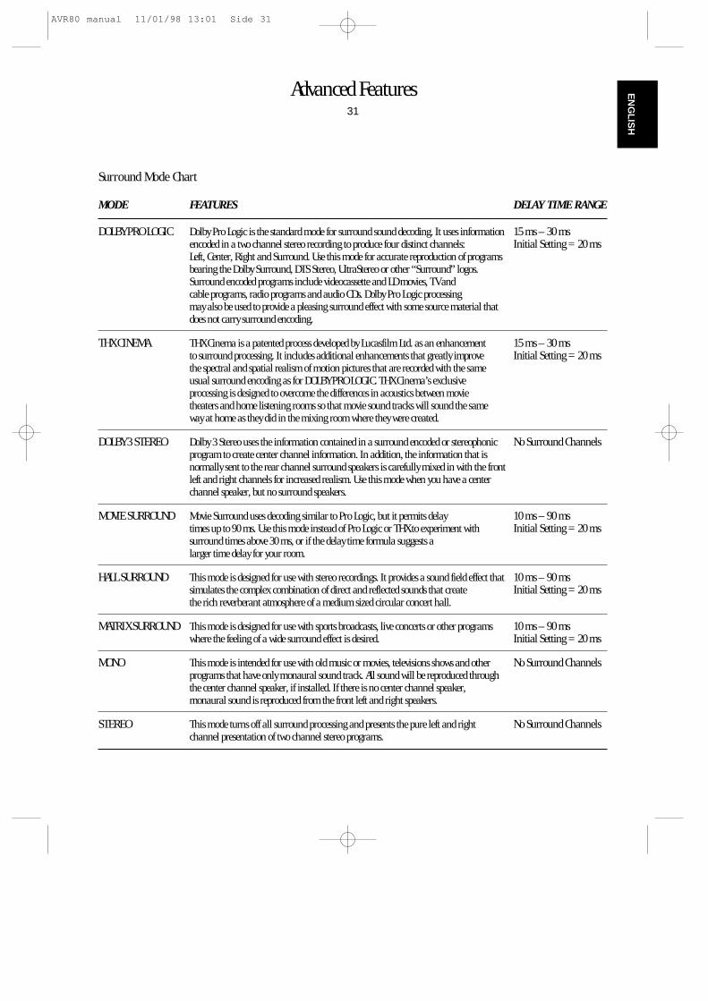
Advanced Features31
EN
GLIS
H
MODE FEATURES DELAY TIME RANGE
DOLBY PRO LOGIC Dolby Pro Logic is the standard mode for surround sound decoding. It uses information 15 ms – 30 msencoded in a two channel stereo recording to produce four distinct channels: Initial Setting = 20 msLeft, Center, Right and Surround. Use this mode for accurate reproduction of programs bearing the Dolby Surround, DTS Stereo, UltraStereo or other “Surround” logos. Surround encoded programs include videocassette and LD movies, TV and cable programs, radio programs and audio CDs. Dolby Pro Logic processing may also be used to provide a pleasing surround effect with some source material that does not carry surround encoding.
THX CINEMA THX Cinema is a patented process developed by Lucasfilm Ltd. as an enhancement 15 ms – 30 msto surround processing. It includes additional enhancements that greatly improve Initial Setting = 20 msthe spectral and spatial realism of motion pictures that are recorded with the same usual surround encoding as for DOLBY PRO LOGIC. THX Cinema’s exclusive processing is designed to overcome the differences in acoustics between movie theaters and home listening rooms so that movie sound tracks will sound the same way at home as they did in the mixing room where they were created.
DOLBY 3 STEREO Dolby 3 Stereo uses the information contained in a surround encoded or stereophonic No Surround Channelsprogram to create center channel information. In addition, the information that is normally sent to the rear channel surround speakers is carefully mixed in with the front left and right channels for increased realism. Use this mode when you have a center channel speaker, but no surround speakers.
MOVIE SURROUND Movie Surround uses decoding similar to Pro Logic, but it permits delay 10 ms – 90 mstimes up to 90 ms. Use this mode instead of Pro Logic or THX to experiment with Initial Setting = 20 mssurround times above 30 ms, or if the delay time formula suggests a larger time delay for your room.
HALL SURROUND This mode is designed for use with stereo recordings. It provides a sound field effect that 10 ms – 90 mssimulates the complex combination of direct and reflected sounds that create Initial Setting = 20 msthe rich reverberant atmosphere of a medium sized circular concert hall.
MATRIX SURROUND This mode is designed for use with sports broadcasts, live concerts or other programs 10 ms – 90 mswhere the feeling of a wide surround effect is desired. Initial Setting = 20 ms
MONO This mode is intended for use with old music or movies, televisions shows and other No Surround Channelsprograms that have only monaural sound track. All sound will be reproduced through the center channel speaker, if installed. If there is no center channel speaker, monaural sound is reproduced from the front left and right speakers.
STEREO This mode turns off all surround processing and presents the pure left and right No Surround Channelschannel presentation of two channel stereo programs.
Surround Mode Chart
AVR80 manual 11/01/98 13:01 Side 31
Multiroom Operation32
EN
GLI
SH
The AVR80 is unique among A/Vreceivers in that it is equipped to operateas the control center for a sophisticatedmultiroom operation with accessories assimple as a remote IR sensor or assophisticated as a specialized externalamplifier and a special version of theworld-famous AudioAccess wall mountedkeypad controls. Although somemultiroom installations will require theservices of a specially trained installer, itis possible for the average do it yourself hobbyist to install a simple remote roomsystem. For additional information onusing the AVR80 in multiroominstallations we suggest that you contactyour dealer or custom installer.
InstallationThe key to remote room operation is tolink the remote room to the AVR80’slocation with wire for an infrared receiverand speakers or an amplifier.
IR LinkThe remote room IR receiver should beconnected to the AVR80 via standardcoaxial cable. Plug the IR connectioncable into the mini jack inside the Multiarea in the middle of the AVR80’s rearpanel.œ
If other Harman Kardon compatiblesource equipment is part of the mainroom installation, the REMOTECONT. OUT jack on the rear panel ∑should be connected to IR IN jack on theCD player or cassette deck. This willenable the remote room location tocontrol source equipment functions aswell as the remote room input andvolume.
NOTE: All remotely controlledcomponents must be linked together in adaisy chain. Connect the IR OUT jack ofone unit to the IR IN of the next toestablish this chain.
Audio LinkDepending on the distance from the AVR80 to the remote room, two options areavailable.
The preferred method is to run highquality, shielded audio interconnect cablefrom the AVR80’s location to the remoteroom. At the remote room, connect theinterconnect cable to a stereo poweramplifier. The amplifier will beconnected to the room’s speakers. Novolume control is required, as the AVR80and the remote IR link will provide thatfunction. At the AVR80, plug the audiointerconnect cable into the MULTI OUTjacks ® at the top left corner of the AVR80’s rear panel.
NOTE: The remote power amplifier musthave signal sensing capability or be lefton constantly to assure automaticoperation at the remote room.
As an alternative, the amplifier may beplaced at the same location as the AVR80,with a standard audio interconnectbetween the two. Speaker wires shouldthen be run to the remote room. Highquality AWG-12 speaker wire is preferred.
IMPORTANT NOTE: Any cables runinside walls should carry safetycertification that is required by the localbuilding and electrical codes. To avoidinterference, audio and speaker cablesshould not be parallel to, or in the sameconduits with AC cables. If you have anyquestions about multi-room wiringconsult your dealer, custom installer orelectrician.
Set-up Once the equipment connections havebeen made, the AVR80 needs to beconfigured for multiroom operation byfollowing these steps:
1. Press the SELECT r to bring theMAIN MENU to the screen (Figure #1).Press the ¤ button q four times untilthe on screen > cursor is pointing toMULTI ROOM SELand pressSELECT r. The video screen will move to the MULTI ROOM
SELECTORmenu (Figure #17).
2. Press the › button q until thedesired input source for the multi roomsystem is selected.
AVR80 manual 11/01/98 13:01 Side 32
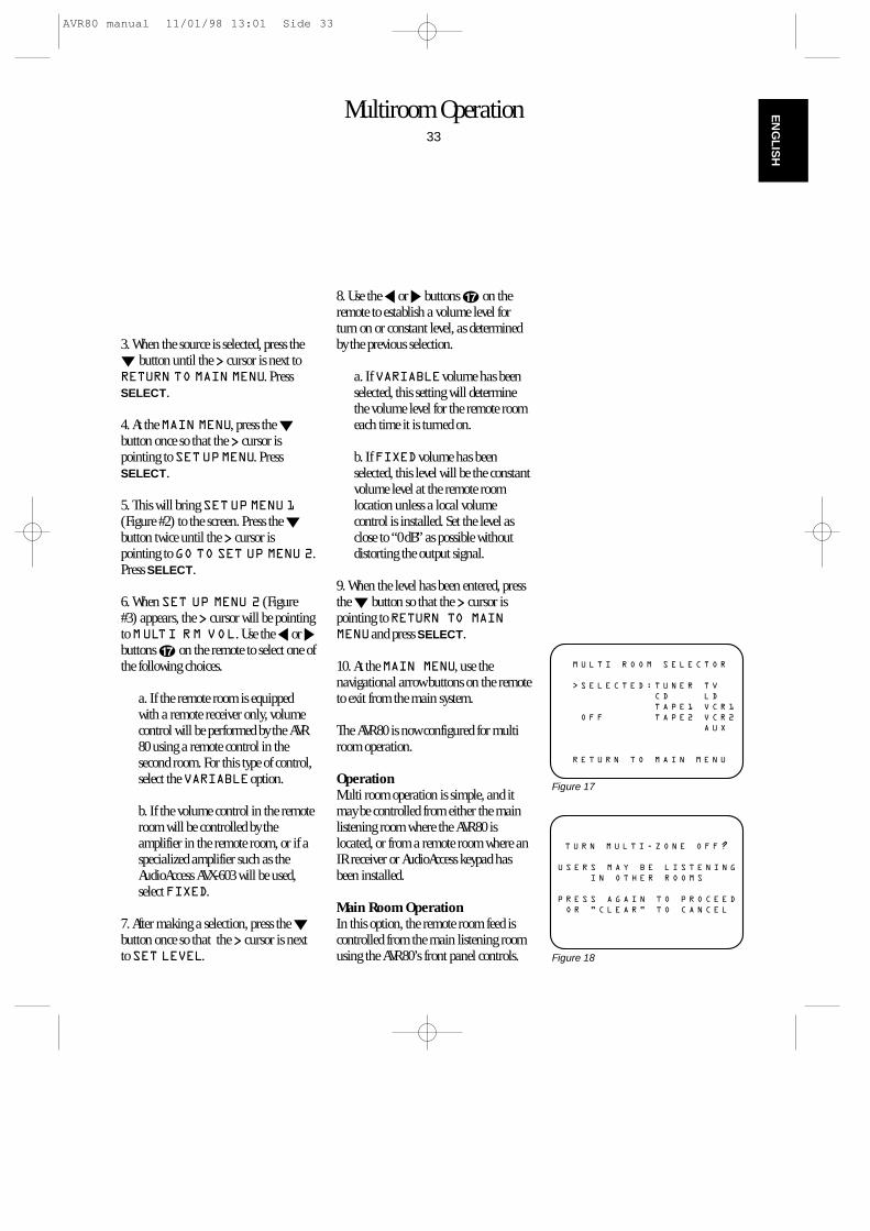
Multiroom Operation33
EN
GLIS
H
3. When the source is selected, press the¤ button until the > cursor is next toRETURN TO MAIN MENU. PressSELECT.
4. At the MAIN MENU, press the ¤button once so that the > cursor ispointing to SETUPMENU. PressSELECT.
5. This will bring SETUP MENU 1(Figure #2) to the screen. Press the ¤button twice until the > cursor ispointing to GO TO SET UP MENU 2.Press SELECT.
6. When SET UP MENU 2 (Figure#3) appears, the > cursor will be pointingto MULTI RM VOL. Use the ‹ or ›buttons q on the remote to select one ofthe following choices.
a. If the remote room is equippedwith a remote receiver only, volumecontrol will be performed by the AVR80 using a remote control in thesecond room. For this type of control,select the VARIABLEoption.
b. If the volume control in the remoteroom will be controlled by theamplifier in the remote room, or if aspecialized amplifier such as theAudioAccess AVX-603 will be used,select FIXED.
7. After making a selection, press the ¤button once so that the > cursor is nextto SET LEVEL.
8. Use the ‹ or › buttons q on theremote to establish a volume level forturn on or constant level, as determinedby the previous selection.
a. If VARIABLEvolume has beenselected, this setting will determinethe volume level for the remote roomeach time it is turned on.
b. If FIXEDvolume has beenselected, this level will be the constantvolume level at the remote roomlocation unless a local volumecontrol is installed. Set the level asclose to “0 dB” as possible withoutdistorting the output signal.
9. When the level has been entered, pressthe ¤ button so that the > cursor ispointing to RETURN TO MAINMENUand press SELECT.
10. At the MAIN MENU, use thenavigational arrow buttons on the remoteto exit from the main system.
The AVR80 is now configured for multiroom operation.
OperationMulti room operation is simple, and itmay be controlled from either the mainlistening room where the AVR80 islocated, or from a remote room where anIR receiver or AudioAccess keypad hasbeen installed.
Main Room OperationIn this option, the remote room feed iscontrolled from the main listening roomusing the AVR80’s front panel controls.
M U L T I R O O M S E L E C T O R
> S E L E C T E D : T U N E R T V
C D L D
T A P E 1 V C R 1
O F F T A P E 2 V C R 2
A U X
R E T U R N T O M A I N M E N U
Figure 17
T U R N M U L T I - Z O N E O F F ?
U S E R S M A Y B E L I S T E N I N G
I N O T H E R R O O M S
P R E S S A G A I N T O P R O C E E D
O R " C L E A R " T O C A N C E L
Figure 18
AVR80 manual 11/01/98 13:01 Side 33
Multiroom Operation34
EN
GLI
SH
To activate the remote room feed, pressthe MULTI button on the front panel 9.This will send the signal of the AVR80’scurrently selected input source to theremote room at the volume levelestablished in SET UP MENU 2.
The MULTI indicator on the front paneldisplay ‚ will flash to indicate that themultiroom system is turned on in thevariable mode, and that Source Linkingis in effect. With Source Link, any changeto the AVR80’s input selection will alsochange the feed to the remote roomlocations. If the input source is changedfrom the remote room, the MULTIindicator will remain lit, but stopflashing.
If the AVR80 is turned off in the mainlistening room, the feed to the remoteroom will continue, although theMULTI indicator will now remainconstantly illuminated.
To turn off the feed to the remote roomeither while the AVR80 is still on, or afterit is turned off, press the MULTI buttonon the front panel. If the MULTI buttonis pressed while the AVR80 is still on andthe on screen video system is engaged, awarning message will appear on thevideo display (Figure #18) to remind youthat people may still be listening to thesystem in the remote room location.
Remote Room Operation In this option, the remote room feed iscontrolled by the use of an AVR80compatible remote control. The remotecommands must be transmitted to theAVR80 via a coaxial link connected to theMULTI input œ on the AVR80’s rearpanel.
Using the remote control in the secondroom press the POWER ON button toturn on the remote room feed. This willactivate the multi room portion of theAVR80 whether or not it may be on in themain listening room.
The initial feed to the remote room willbe the last station selected by the tuner.Any other AVR80 input source maysubsequently be selected using the sourcebuttons on the remote control.
The initial volume at the remote roomwill be the level established using theoptions in SET UP MENU 2.
If IR connections have been made to thesource playback equipment, it is alsopossible to control the functions of thoseunits via the second room remote.Consult with your dealer or custominstaller for additional information onthis type of installation.
When the remote room is controlling theAVR80 via the IR link, the MULTIindicator on the AVR80’s front panel willremain constantly lit.
NOTE: Whenever the AVR80 is in amultiroom mode, the MULTI indicatorwill flash briefly whenever a command istransmitted by the remote room locationand received by the AVR80.
The AVR80 may also be remoted by akeypad (from Audio Access). Thereforeconnect the keypad interface to jack πon the AVR80´s rear side.
AVR80 manual 11/01/98 13:01 Side 34
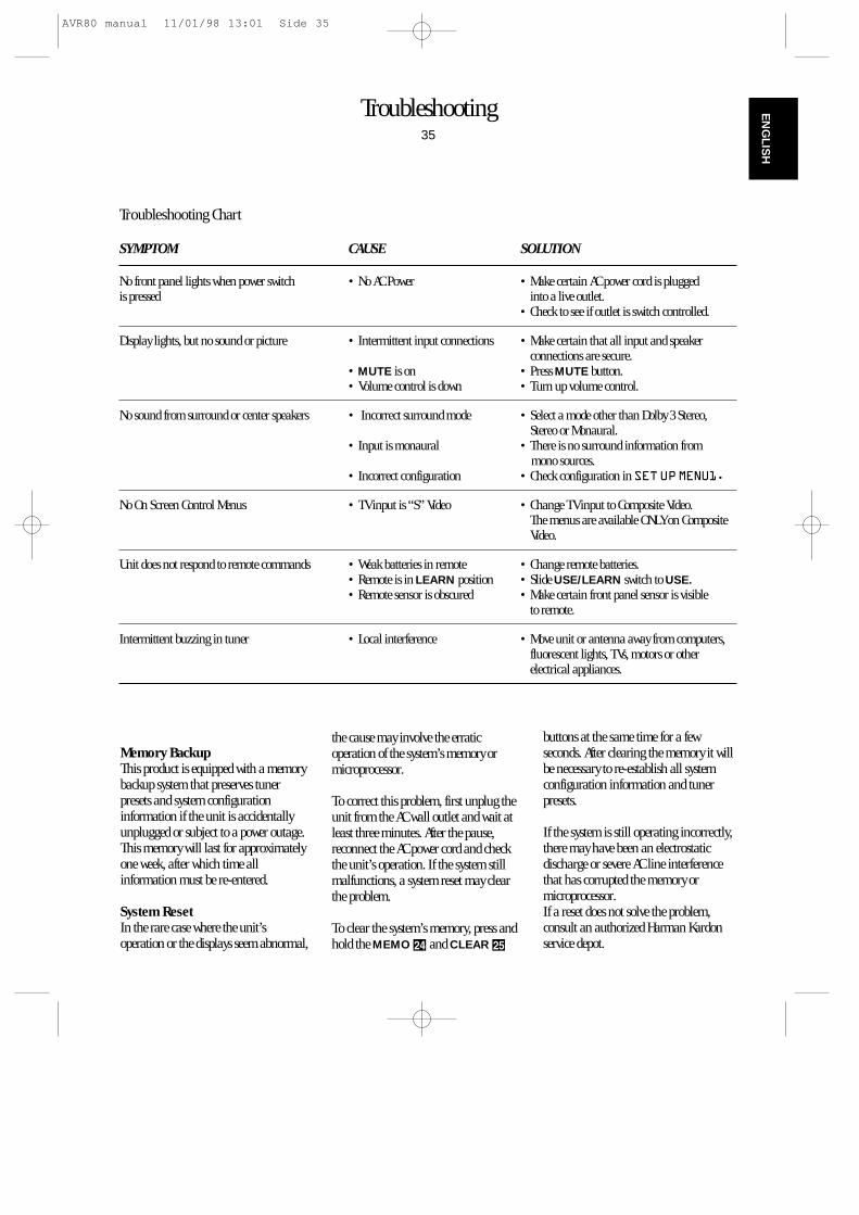
Troubleshooting35
EN
GLIS
H
SYMPTOM CAUSE SOLUTION
No front panel lights when power switch • No AC Power • Make certain AC power cord is plugged is pressed into a live outlet.
• Check to see if outlet is switch controlled.
Display lights, but no sound or picture • Intermittent input connections • Make certain that all input and speaker connections are secure.
• MUTE is on • Press MUTE button.• Volume control is down • Turn up volume control.
No sound from surround or center speakers • Incorrect surround mode • Select a mode other than Dolby 3 Stereo, Stereo or Monaural.
• Input is monaural • There is no surround information from mono sources.
• Incorrect configuration • Check configuration in SETUPMENU1.
No On Screen Control Menus • TV input is “S” Video • Change TV input to Composite Video. The menus are available ONLY on CompositeVideo.
Unit does not respond to remote commands • Weak batteries in remote • Change remote batteries.• Remote is in LEARN position • Slide USE/LEARN switch to USE.• Remote sensor is obscured • Make certain front panel sensor is visible
to remote.
Intermittent buzzing in tuner • Local interference • Move unit or antenna away from computers,fluorescent lights, TVs, motors or otherelectrical appliances.
Troubleshooting Chart
Memory BackupThis product is equipped with a memorybackup system that preserves tunerpresets and system configurationinformation if the unit is accidentallyunplugged or subject to a power outage.This memory will last for approximatelyone week, after which time allinformation must be re-entered.
System ResetIn the rare case where the unit’soperation or the displays seem abnormal,
the cause may involve the erraticoperation of the system’s memory ormicroprocessor.
To correct this problem, first unplug theunit from the AC wall outlet and wait atleast three minutes. After the pause,reconnect the AC power cord and checkthe unit’s operation. If the system stillmalfunctions, a system reset may clearthe problem.
To clear the system’s memory, press andhold the MEMO Ú and CLEAR Û
buttons at the same time for a fewseconds. After clearing the memory it willbe necessary to re-establish all systemconfiguration information and tunerpresets.
If the system is still operating incorrectly,there may have been an electrostaticdischarge or severe AC line interferencethat has corrupted the memory ormicroprocessor. If a reset does not solve the problem,consult an authorized Harman Kardonservice depot.
AVR80 manual 11/01/98 13:01 Side 35
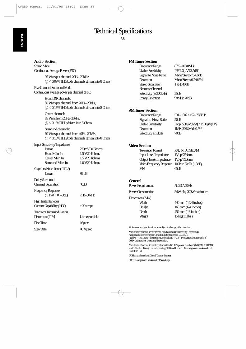
Technical Specifications36
EN
GLI
SH
Audio SectionStereo Mode Continuous Average Power (FTC)
95 Watts per channel 20Hz–20kHz:@ < 0.09% THD, both channels driven into 8 Ohms
Five Channel Surround Mode Continuous average power per channel (FTC)
Front L&R channels:85 Watts per channel from 20Hz–20KHz,@ < 0.15% THD, both channels driven into 8 Ohms
Center channel:85 Watts from 20Hz–20kHz,@ < 0.15% THD, driven into 8 Ohms
Surround channels:60 Watts per channel from 40Hz–20kHz,@ < 0.15% THD, both channels driven into 8 Ohms
Input Sensitivity/ImpedanceLinear 220mV/50 KohmsFront Main In 1.5 V/20 KohmsCenter Main In 1.5 V/20 KohmsSurround Main In 1.0 V/20 Kohms
Signal to Noise Rate (IHF-A)Linear 95 dB
Dolby Surround Channel Separation 40dB
Frequency Response @ 1W (+0, –3dB) 7Hz–80kHz
High Instantaneous Current Capability (HCC) ±30 amps
Transient Intermodulation Distortion (TIM) Unmeasurable
Rise Time 16µsec
Slew Rate 40 V/µsec
FM Tuner SectionFrequency Range 87.5–108.0MHzUsable Sensitivity IHF 1.3 µV/13.5dBfSignal to Noise Ratio Mono/Stereo 76/68dBDistortion Mono/Stereo 0.2/0.5%Stereo Separation 1 kHz 40dBAlternate ChannelSelectivity (±300kHz) 55dBImage Rejection 98MHz: 70dB
AM Tuner SectionFrequency Range 531–1602 / 152–282kHzSignal-to-Noise Ratio 50dBUsable Sensitivity Loop: 500µV (MW) / 1500µV (LW)Distortion 1kHz, 30% Mod: 0.5%Selectivity ±18kHz 70dB
Video SectionTelevision Format PAL, NTSC, SECAMInput Level/Impedance 1Vp-p/75ohmsOutput Level/Impedance 1Vp-p/75ohmsVideo Frequency Response 10Hz to 8MHz (–3dB)S/N 65dB
GeneralPower Requirement AC 230V 50Hz
Power Consumption 54W idle, 700W maximum
Dimension (Max)Width 440 mm (17.4 inches)Height 160 mm (6.4 inches)Depth 459 mm (18 inches)Weight 15 kg (31 lbs.)
All features and specifications are subject to change without notice.
Manufactured under license from Dolby Laboratories Licensing Corporation.Additionally licensed under Canadian patent number 1,037,877.“Dolby,” “Pro Logic.” the double-D symbol and “AC-3” are registered trademarks of Dolby Laboratories Licensing Corporation.
Manufactured under license from Lucasfilm Ltd. U.S. patent numbers 5,043,970; 5,189,703; and 5,222,059. Foreign patents pending. THX and Home THX are registered trademarks ofLucasfilm Ltd.
DTS is a trademark of Digital Theater Systems
SDDS is a registered trademark of Sony Corp.
AVR80 manual 11/01/98 13:01 Side 36