hard start/no-start diagnosis hard start/no-start
TRANSCRIPT

3/15/2014 Printer Friendly View
http://www1.prodemand.com/Print/Index?content=tabs&module=true&tab=true&terms=true&ymms=false&className= 1/21
INTRODUCTION
Since many computer-controlled and monitored components set a Diagnostic Trouble Code (DTC) if they
malfunction, perform QUICK TEST in TESTS W/CODES - 7.3L DIESEL article. Service DTCs as necessary.
NOTE: Testing individual components does not
isolate short or open circuits. Perform all voltage tests
with a Digital Volt-Ohmmeter (DVOM) with a minimum
10-megohm input impedance, unless stated otherwise
in test procedure. Use ohmmeter to isolate shorted or
open wiring harness.
HARD START/NO-START DIAGNOSIS
NOTE: Repair each problem detected before
going on to the next step. If repair corrects the
original complaint, it will not be necessary to proceed
to the next step or diagnostic procedure. However, if
complaint is not corrected, continue with the testing
until complaint is corrected.
HARD START/NO-START DIAGNOSIS > VISUAL INSPECTION > DIAGNOSTIC AIDS
Perform visual inspection to check general engine condition and look for obvious causes of hard start or no-
start conditions. Possible causes of a hard or no-start condition are:
Loose or leaking fuel supply lines could cause system to lose prime.
Kinked or blocked fuel supply lines.
Loose or damaged Camshaft Position (CMP) sensor and Injection Pressure Regulator (IPR)
wiring harness connectors.
1. Inspect fuel system, including fuel tank and fuel lines for kinks, bends and leakage.
Repair as necessary. Check oil lines and high pressure oil pump for leaks. Repair
as necessary. Inspect cooling system. Check radiator and heater hoses for leaks.
2. Check Powertrain Control Module (PCM) and Injector Driver Module (IDM) wiring
harness connectors for damaged pins, corrosion and loose wires. Repair as
necessary.
HARD START/NO-START DIAGNOSIS > CHECK ENGINE OIL > DIAGNOSTIC AIDS
Checking engine oil helps determine if there is enough engine oil to operate fuel injectors. If there is little or
no oil in crankcase, injectors will not operate.
1. Ensure vehicle is on level ground. Check engine oil. If oil is overfilled, engine may have been
incorrectly serviced, or oil is diluted with fuel and is filling crankcase. Repair as necessary.
2. Inspect oil color. A milky white color indicates possible coolant contamination. Determine cause
and repair as necessary. If oil level is low, top off oil. Ensure oil is correct type and viscosity.
ENGINE CONTROLS - SYSTEM & COMPONENT TESTS - 7.3L DIESEL
1997 Ford F-Super Duty 7.3L Eng

3/15/2014 Printer Friendly View
http://www1.prodemand.com/Print/Index?content=tabs&module=true&tab=true&terms=true&ymms=false&className= 2/21
3. Remove plug in top of oil reservoir and check oil level. If oil level is within 1" (25.4 mm) of fill hole,
level is okay. If oil level is not within 1" (25.4 mm) of fill hole, top off fluid. Attempt to start vehicle. If
vehicle starts, determine cause of low oil level and repair as necessary.
HARD START/NO-START DIAGNOSIS > CHECK FOR INTAKE/EXHAUST RESTRICTION >
DIAGNOSTIC AIDS
This is a visual inspection to determine if an air intake or exhaust restriction is contributing to a hard or no-
start condition. If engine does not start and a air intake or exhaust restriction exists, a large amount of
Black/Blue smoke will exist while cranking engine.
1. Inspect air cleaner assembly for proper installation. Ensure air ducting is not blocked or collapsed.
Inspect filter minder on filter housing to assure intake restriction is below Red marks. Replace filter
as necessary.
2. While cranking engine, inspect turbocharger exhaust backpressure butterfly bellcrank. Ensure
bellcrank is not closed. When tang is against the stop, valve is fully open. See Fig 1.

3/15/2014 Printer Friendly View
http://www1.prodemand.com/Print/Index?content=tabs&module=true&tab=true&terms=true&ymms=false&className= 3/21
HARD START/NO-START DIAGNOSIS > CHECK FUEL SUPPLY & QUALITY >
DIAGNOSTIC AIDS
Purpose of this test is to see if fuel system is getting sufficient clean fuel to start and run engine.
1. Connect a hose to fuel drain line at bottom of fuel filter housing. Place other end of hose into a
suitable container. Open fuel drain. Crank engine and observe fuel. Fuel flow should be a steady
stream.
Fig 1: Identifying Open Exhaust Backpressure Control Valve Position
Courtesy of FORD MOTOR CO.

3/15/2014 Printer Friendly View
http://www1.prodemand.com/Print/Index?content=tabs&module=true&tab=true&terms=true&ymms=false&className= 4/21
NOTE: Fuel should be straw colored, but not
cloudy. Fuel should be free of water and
contaminates. Fuel dyed Red or Blue indicates
off-highway fuel.
2. While cranking engine, check WATER IN FUEL warning light indicator. If warning light is on, fuel is
probably contaminated with water. Service fuel system as necessary. If engine oil is present in fuel,
injector "O" ring(s) may be defective. Perform INJECTION CONTROL PRESSURE LEAK TEST .
Repair oil leaks as necessary.
NOTE: Some sediment and water may be present
in fuel sample if fuel filter has not been serviced for a
prolonged period of time. A second sample may be
necessary to determine fuel quality.
HARD START/NO-START DIAGNOSIS > FUEL PUMP PRESSURE TEST > MECHANICAL
FUEL PUMP
NOTE: For fuel pressure specifications, see
FUEL PRESSURE SPECIFICATIONS article.
1. Connect Engine Pressure Test Kit (014-00761) and Adapter (014-00931-3) to Schrader valve.
Schrader valve is part of fuel regulator block. Connect fuel line between adapter and 0-160 psi (0-
1103 kPa) gauge (No. 6) at engine pressure tester. See Figure.
2. Crank engine (minimum of 100 RPM) for 20 seconds and observe fuel pressure gauge. If fuel
pressure is as specified, fuel pressure is okay. If fuel pressure is less than specified, replace fuel
filter and retest. Cycle ignition switch several times to purge air from system. If fuel pressure is still
low, check the following:
1. Check fuel level in gas tank.
2. Disassemble, inspect and clean fuel pressure regulator valve. See Figure.
3. Check for bent or damaged fuel lines. Check for blockage at fuel pick-up tube.
4. Check for loose fuel line on suction side of fuel system. If fuel line is tight, replace fuel
pump and retest.
HARD START/NO-START DIAGNOSIS > FUEL PUMP PRESSURE TEST > ELECTRIC
FUEL PUMP
NOTE: For fuel pressure specifications, see
FUEL PRESSURE SPECIFICATIONS article.
1. Ensure fuel tank has fuel. Ensure fuel pump has power and ground. With ignition on, battery
voltage should be present at fuel pump for about 20 seconds. If voltage is as specified, go to next
step. If voltage is not as specified, perform CIRCUIT TEST FK in TESTS W/CODES - 7.3L DIESEL
article.

3/15/2014 Printer Friendly View
http://www1.prodemand.com/Print/Index?content=tabs&module=true&tab=true&terms=true&ymms=false&className= 5/21
2. Remove cover and 1/8" pipe plug from top rear of left cylinder head. Install fuel pressure gauge.
Check fuel pressure with engine cranking or running. For fuel pressure specifications, see FUEL
PRESSURE SPECIFICATIONS article. If fuel pressure is not as specified, go to FUEL PUMP
PRESSURE TEST under ENGINE PERFORMANCE DIAGNOSIS .
HARD START/NO-START DIAGNOSIS > CHECK FOR DIAGNOSTIC TROUBLE CODES
If all steps under QUICK TEST in TESTS W/CODES - 7.3L DIESEL have been successfully completed, and
a System Pass (DTC P1111 on Federal vehicles or no DTCs on Calif. vehicles) is present, go to CHECK
PARAMETER IDENTIFICATION (PID) DURING CRANKING. If QUICK TEST has not been completed, perform
QUICK TEST. If any DTCs are present, service DTCs as necessary.
HARD START/NO-START DIAGNOSIS > CHECK PARAMETER IDENTIFICATION (PID)
DURING CRANKING > DIAGNOSTIC AIDS
Purpose of this test is to verify Powertrain Control Module (PCM) power-up during cranking. Lack of power
at PCM during cranking can cause a no-start condition and a fault code loss.
1. Check VPWR PID Connect New Generation Star (NGS) scan tool to Data Link Connector (DLC).
Using scan tool, access VPWR PID from PID/DATA monitor menu. See ADDITIONAL SYSTEM
Fig 1: Removing Fuel Pressure Regulator Valve (Vehicles With Mechanical Fuel Pump)
Courtesy of FORD MOTOR CO.

3/15/2014 Printer Friendly View
http://www1.prodemand.com/Print/Index?content=tabs&module=true&tab=true&terms=true&ymms=false&className= 6/21
FUNCTIONS in TESTS W/CODES - 7.3L DIESEL article. Crank engine while monitoring PID
reading. If PID reading indicates more than 7 volts, go to next step. If PID reading indicates 7 volts
or less, check charging circuit, power and ground circuits. See CIRCUIT TEST A in TESTS
W/CODES - 7.3L DIESEL article.
2. Check RPM PID Using scan tool, access RPM PID from PID/DATA monitor menu. Crank engine
while monitoring PID reading. If PID reading indicates more than 100 RPM, go to next step. If PID
reading indicates 100 RPM or less, check Camshaft Position (CMP) sensor circuit. See CIRCUIT
TEST DG in TESTS W/CODES - 7.3L DIESEL article.
3. Check ICP PID Using scan tool, access ICP PID from PID/DATA monitor menu. Crank engine while
monitoring PID reading. If PID reading indicates 500 psi (3448 kPa) or more, go to next step. If PID
reading indicates less than 500 psi (3448 kPa), injectors are not being energized because of
insufficient pressure. Perform INJECTION CONTROL PRESSURE LEAK TEST .
4. Check Fuel Pulse Width Using scan tool, access FUEL PW PID from PID/DATA monitor menu.
Crank engine while monitoring PID reading. If PID reading indicates 1-6 milliseconds, go to GLOW
PLUG SYSTEM OPERATION TEST . If PID reading does not indicate 1-6 milliseconds and VPWR,
RPM and ICP PID readings are correct, Camshaft Position (CMP) sensor signal fault. See CIRCUIT
TEST DG in TESTS W/CODES - 7.3L DIESEL article.
HARD START/NO-START DIAGNOSIS > INJECTION CONTROL PRESSURE LEAK TEST >
DIAGNOSTIC AIDS
Removing Injection Control Pressure (ICP) sensor and inspecting level in oil rail will determine if oil is being
supplied to rail. Removing inspection plug in top of reservoir will help determine if reservoir is full. A
reservoir that drains back after engine has not been operated for a long period of time can cause a hard
start condition.
HARD START/NO-START DIAGNOSIS > INJECTION CONTROL PRESSURE LEAK TEST >
RIGHT CYLINDER HEAD CHECK
1. Perform step 3) under CHECK PARAMETER IDENTIFICATION (PID) DURING CRANKING (if not
already completed). Remove high pressure hose from right cylinder head. Using Fuel/Oil/Turbo
Protector Cap Set (T94T-9395-AH), install appropriate cap on high pressure hose fitting on
cylinder head. Using Oil High Pressure Leakage Test Adapter Set (D94T-6600-A), install plug into
high pressure hose.
WARNING: In the following step, engine may
start.
2. Install ICP/EBP Adapter Cable (D94T-50-A) between ICP sensor and sensor wiring harness
connector. Connect a DVOM between SIG RTN circuit (Black wire) and ICP Signal circuit (Green
wire) at ICP/EBP adapter cable. Observe DVOM and crank engine. Voltage reading should be 1-4
volts.
3. If engine starts, or if ICP PID reading indicates 500 psi (3448 kPa) or more, an injection control
pressure oil leak exists in right cylinder head. Inspect fuel system for oil contamination.
4. If no oil is present in fuel system, remove cap and plug, and reinstall high pressure hose to right
cylinder head. Remove right valve cover. Crank engine, and inspect injector body and injector
bore area for oil leakage. Repair as necessary. If engine does not start, or ICP PID is still less than
500 psi (3448 kPa), perform LEFT CYLINDER HEAD CHECK.
HARD START/NO-START DIAGNOSIS > INJECTION CONTROL PRESSURE LEAK TEST >

3/15/2014 Printer Friendly View
http://www1.prodemand.com/Print/Index?content=tabs&module=true&tab=true&terms=true&ymms=false&className= 7/21
LEFT CYLINDER HEAD CHECK
1. Remove high pressure hose from left cylinder head. Using fuel/oil/turbo protector cap set, install
appropriate cap on high pressure hose fitting on cylinder head. Using oil high pressure leakage
test adapter set, install ICP adapter into high pressure hose. See Fig 1.
2. Remove ICP sensor and install sensor in end of ICP adapter. Install ICP/EBP Adapter Cable
(D94T-50-A) between ICP sensor and sensor wiring harness connector. Connect a DVOM
between SIG RTN circuit (Black wire) and ICP Signal circuit (Green wire) at ICP/EBP adapter cable.
Observe DVOM and crank engine. Voltage reading should be 1-4 volts.
WARNING: In the following step, engine may
start.
3. If engine starts, or if ICP PID reading indicates 500 psi (3448 kPa) or more, an injection control
pressure oil leak exists in left cylinder head. Reconnect high pressure hose to left cylinder head.
Remove left valve cover. Crank engine, and inspect injector body and injector bore area for oil
leakage. Repair as necessary.
4. If injection control pressure is still low after completing both right and left cylinder head checks and
no oil leaks have been found, remove high pressure hose from right and left cylinder heads. Using
fuel/oil/turbo protector cap set, install appropriate cap on high pressure hose fitting on each
cylinder head.
5. Using oil high pressure leakage test adapter set, install plug into each high pressure hose. Both
high pressure lines should now be blocked off. Using scan tool, observe ICP PID reading while
cranking engine.
6. If PID reading is still less than 500 psi (3448 kPa), replace Injection Pressure Regulator (ICP) with
a known good ICP and retest. If PID reading is now 500 psi (3448 kPa) or more, replace ICP. If PID
reading is still less than 500 psi (3448 kPa), high pressure pump or high pressure pump drive gear
is faulty. Repair as necessary.

3/15/2014 Printer Friendly View
http://www1.prodemand.com/Print/Index?content=tabs&module=true&tab=true&terms=true&ymms=false&className= 8/21
HARD START/NO-START DIAGNOSIS > GLOW PLUG SYSTEM OPERATION TEST
Question: glow plug ohms
HARD START/NO-START DIAGNOSIS > GLOW PLUG SYSTEM OPERATION TEST >
DIAGNOSTIC AIDS
Insufficient glow plug "On" time will not allow enough heat to accumulate in combustion chamber resulting in
a hard start condition. If glow plug system "On" time is insufficient, probable cause is a faulty wiring harness
connector, bad ground connection or defective glow plug relay. If glow plug resistance to ground is high,
probable cause is an open circuit in Under Valve Cover (UVC) wiring harness or an open glow plug.
1. Connect a DVOM between ground and Black/Orange wire at glow plug relay. See Fig 1. Turn
ignition on. If battery voltage is present, go to next step. If battery voltage is not present, locate
and repair open circuit in Black/Orange wire between glow plug relay and starter relay.
Fig 1: Equipment Hookup For Injection Control Pressure Test
Courtesy of FORD MOTOR CO.

3/15/2014 Printer Friendly View
http://www1.prodemand.com/Print/Index?content=tabs&module=true&tab=true&terms=true&ymms=false&className= 9/21
2. Turn ignition off. Connect DVOM between ground and Brown wire at glow plug relay. Turn ignition
on and note how long is takes for glow plug relay to energize and de-energize ("On" time). Relay
will make a loud click noise when it energizes. If relay "On" time is not as specified, replace relay.
See GLOW PLUG RELAY SPECIFICATIONS table. If "On" time is as specified, go to next step.
GLOW PLUG RELAY SPECIFICATIONS
Engine Oil Temperature - °F (°C) "On" Time - Seconds
14 (-10) 120
68 (20) 70
122 (50) 40
131 (55) 60
Specification listed is with vehicle at sea level and battery voltage at 12 volts.
Specification is approximate.
(1)
(1)
Fig 1: Checking Power To Glow Plug Relay
Courtesy of FORD MOTOR CO.

3/15/2014 Printer Friendly View
http://www1.prodemand.com/Print/Index?content=tabs&module=true&tab=true&terms=true&ymms=false&className= 10/21
NOTE: Each valve cover gasket has 2 fuel
injector connectors that are part of the gasket.
Each connector is responsible for 2 fuel
injectors. If connector is faulty, replace valve
cover gasket.
3. Turn ignition off. Disconnect all 4 injector connectors at valve cover gaskets. Install Glow Plug
Injector Adapter (014-00935) to any injector connector at valve cover gasket. See Fig 2.
NOTE: If all injector connectors are not
disconnected at both valve cover gaskets,
resistance measurements will be incorrect.
4. Measure resistance between ground and each glow plug test point at glow plug injector adapter. If
all readings are .1-2.0 ohms, go to next step. If any reading is not .1-2.0 ohms, probable cause is
an open in Under Valve Cover (UVC) wiring harness or an open glow plug. Repair as necessary.
5. Measure resistance between Brown wire at glow plug relay and each glow plug test point at glow
plug injector adapter. If all readings are .1-1.0 ohm, no problem is indicated at this time. If any
reading is not .1-1.0 ohm, locate and repair open circuit.
Fig 2: Checking Glow Plug Resistance
Courtesy of FORD MOTOR CO.

3/15/2014 Printer Friendly View
http://www1.prodemand.com/Print/Index?content=tabs&module=true&tab=true&terms=true&ymms=false&className= 11/21
ENGINE PERFORMANCE DIAGNOSIS
NOTE: Repair each problem detected before
going on to the next step. If repair corrects the
original complaint, it will not be necessary to proceed
to the next step or diagnostic procedure. However, if
complaint is not corrected, continue with the testing
until complaint is corrected.
ENGINE PERFORMANCE DIAGNOSIS > VISUAL INSPECTION > DIAGNOSTIC AIDS
Perform visual inspection to check general engine condition and look for obvious causes of a loss of
performance.
1. Check for disconnected or pinched Manifold Absolute Pressure (MAP) sensor hose. Inspect fuel
system, including fuel tank and fuel lines for kinks, bends and leakage. Repair as necessary.
Check oil lines and high pressure oil pump for leaks. Repair as necessary.
2. Inspect cooling system. Check radiator and heater hoses for leaks. Check Powertrain Control
Module (PCM) and Injector Driver Module (IDM) wiring harness connectors for damaged pins,
corrosion and loose wires. Repair as necessary.
ENGINE PERFORMANCE DIAGNOSIS > CHECK FUEL QUALITY > DIAGNOSTIC AIDS
Purpose of this test is to see if fuel system is getting sufficient clean fuel for engine to operate properly. Fuel
should be straw colored, but not cloudy. Fuel dyed Red or Blue indicates off-highway fuel. Cloudy fuel
indicates fuel may not be a suitable grade for cold temperatures. Excessive water or contaminants may
indicate fuel system and tank may need to be flushed.
1. Connect a hose to fuel drain line at bottom of fuel filter. Place other end of hose into a suitable
container. Open fuel drain. Start engine and observe fuel. Fuel flow should be a steady stream.
Turn ignition off.
2. Turn ignition on. Check WATER IN FUEL warning light indicator. If warning light is on, fuel is
contaminated with water. Service fuel system as necessary. If engine oil is present in fuel, injector
"O" ring maybe defective. Perform INJECTION CONTROL PRESSURE LEAK TEST under HARD
START/NO START DIAGNOSIS. Repair oil leaks as necessary.
NOTE: Some sediment and water may be present
in fuel sample if fuel filter has not been serviced for a
prolonged period of time. A second sample may be
necessary to determine fuel quality.
ENGINE PERFORMANCE DIAGNOSIS > CHECK ENGINE OIL > DIAGNOSTIC AIDS
Checking engine oil helps determine if there is enough engine oil to operate fuel injectors. If there is little or
no oil in crankcase, injectors will not operate.
1. Ensure vehicle is on level ground. Check engine oil. If oil is overfilled, engine may have been
incorrectly serviced, or fuel is diluting oil and filling crankcase. Repair as necessary.
2. Inspect oil color. A milky white color indicates possible coolant contamination. Determine cause
and repair as necessary. If oil level is low, top off oil. Ensure oil is correct type and viscosity.

3/15/2014 Printer Friendly View
http://www1.prodemand.com/Print/Index?content=tabs&module=true&tab=true&terms=true&ymms=false&className= 12/21
3. Remove plug in top of oil reservoir and check oil level. If oil level is within 1" (25.4 mm) of oil fill
hole, level is okay. If oil level is not within 1" (25.4 mm) of oil fill hole, check and repair cause of low
engine oil. Top off engine oil.
ENGINE PERFORMANCE DIAGNOSIS > CHECK FOR INTAKE RESTRICTION >
DIAGNOSTIC AIDS
This is a visual inspection to determine if an air intake restriction is contributing to a low power condition. If
engine has a high intake restriction, a large amount of Black or Blue smoke may exist.
ENGINE PERFORMANCE DIAGNOSIS > CHECK FOR INTAKE RESTRICTION > CHECK
AIR FILTER
Inspect air cleaner assembly for proper installation. Ensure air ducting is not blocked or collapsed. Inspect
filter minder on filter housing to ensure intake restriction is below Red marks. Replace filter as necessary.
ENGINE PERFORMANCE DIAGNOSIS > CHECK FOR DIAGNOSTIC TROUBLE CODES
Question: 7.3 eng miss
If all steps under QUICK TEST in TESTS W/CODES - 7.3L DIESEL have been successfully completed, and
a System Pass (DTC P1111 on Federal vehicles or no DTCs on Calif. vehicles) is present, go to FUEL
PUMP PRESSURE TEST. If QUICK TEST has not been completed, perform QUICK TEST. If any DTCs are
present, service DTCs as necessary.
ENGINE PERFORMANCE DIAGNOSIS > FUEL PUMP PRESSURE TEST
NOTE: If HIGH FUEL RESTRICTION indicator
light is on, a restricted fuel filter may be causing low
fuel pressure.
ENGINE PERFORMANCE DIAGNOSIS > FUEL PUMP PRESSURE TEST > MECHANICAL
FUEL PUMP
NOTE: For fuel pressure specifications, see
FUEL PRESSURE SPECIFICATIONS article.
1. Connect Engine Pressure Tester (014-00761) and Adapter (014-00931-3) to Schrader valve.
Schrader valve is part of fuel regulator block. Connect fuel line between adapter and 0-160 psi (0-
1103 kPa) gauge (No. 6) at engine pressure tester. See Fig 1.

3/15/2014 Printer Friendly View
http://www1.prodemand.com/Print/Index?content=tabs&module=true&tab=true&terms=true&ymms=false&className= 13/21
2. Start engine and allow it to idle. Observe fuel pressure gauge and briefly raise engine speed to
3500 RPM. For fuel pressure specifications, see FUEL PRESSURE SPECIFICATIONS article. If fuel
pressure is as specified, fuel pressure is okay. If fuel pressure is not as specified, replace fuel filter
and retest. Cycle ignition switch several times to purge air from system. If fuel pressure is still low,
go to next step.
3. Disconnect short fuel hose at fuel inlet line. Hose is located on left side of engine, close to frame
rail. The larger of the 2 lines is the fuel inlet. The smaller line is the fuel return. Connect Fuel
Pressure Adapter (014-00931-2) between fuel inlet line and vacuum gauge (0-30 in. Hg) of engine
pressure tester.
4. Start engine and allow it to idle. Observe vacuum gauge and briefly raise engine speed to 3500
RPM. If vacuum is 6 in. Hg or less, no restriction exist at this time. Check fuel regulator valve for
sticking or debris. If vacuum is more than 6 in. Hg, check for blockage between pump and fuel
tank. Repair as necessary.
ENGINE PERFORMANCE DIAGNOSIS > FUEL PUMP PRESSURE TEST > ELECTRIC
FUEL PUMP
1. Ensure fuel tank has fuel. Ensure fuel pump has power and ground. With ignition on, battery
voltage should be present at fuel pump for about 20 seconds. If voltage is as specified, go to next
step. If voltage is not as specified, perform CIRCUIT TEST FK in TESTS W/CODES - 7.3L DIESEL
article.
Fig 1: Identifying Engine Pressure Tester
Courtesy of FORD MOTOR CO.

3/15/2014 Printer Friendly View
http://www1.prodemand.com/Print/Index?content=tabs&module=true&tab=true&terms=true&ymms=false&className= 14/21
2. Remove fuel line to inlet side of fuel pump. Install Fuel Pressure Adapter (014-00931-2) between
fuel inlet line and fuel pump. Connect fuel pressure adapter to vacuum gauge (0-30 in. Hg) of
Engine Pressure Tester (014-00761). See Figure.
3. Start engine and allow it to idle. Observe vacuum gauge and briefly raise engine speed to 3500
RPM. If vacuum is 6 in. Hg or less, no restriction exist at this time. Go to next step. If vacuum is
more than 6 in. Hg, check for blockage between pump and fuel tank. Repair as necessary.
4. Remove fuel pressure adapter and reconnect fuel line to inlet side of fuel pump. Remove fuel line
from outlet side of fuel pump. Install fuel pressure adapter between fuel outlet line and fuel pump.
Connect fuel pressure adapter to 0-160 psi (0-1103 kPa) gauge (No. 6) at engine pressure tester.
See Figure.
5. Start engine and allow it to idle. Observe fuel pressure gauge and briefly raise engine speed to
3500 RPM. For fuel pressure specifications, see FUEL PRESSURE SPECIFICATIONS article. If fuel
pressure is as specified, fuel pressure is okay. Go to next step. If fuel pressure is not as specified,
check fuel regulator valve for sticking or debris. See Fig 1. Repair as necessary and retest. If fuel
regulator valve is okay, replace fuel pump and retest.
6. Remove cover and 1/8" pipe plug from top rear of left cylinder head. Install fuel pressure gauge.
Start engine. Check fuel pressure with full load on engine. For fuel pressure specifications, see
FUEL PRESSURE SPECIFICATIONS article. DO NOT brake torque engine for more than 10
seconds. If fuel pressure is as specified, go to next step. If fuel pressure is not as specified,
replace fuel filter and retest. If fuel pressure is still low, replace left fuel check valve. Check valve is
located in front of left cylinder head between fuel inlet line and cylinder head.
7. Remove 1/8" pipe plug from top front of right cylinder head. It may be necessary to remove
generator and bracket to access pipe plug. Install fuel pressure gauge. Start engine. Check fuel
pressure with full load on engine. For fuel pressure specifications, see FUEL PRESSURE
SPECIFICATIONS article. DO NOT brake torque engine for more than 10 seconds. If fuel pressure
is as specified, fuel pressure is okay. If fuel pressure is not as specified, replace right fuel check
valve. Check valve is located in rear of right cylinder head between fuel inlet line and cylinder
head.

3/15/2014 Printer Friendly View
http://www1.prodemand.com/Print/Index?content=tabs&module=true&tab=true&terms=true&ymms=false&className= 15/21
ENGINE PERFORMANCE DIAGNOSIS > CHECK FOR AIR IN FUEL SYSTEM > WITH
MECHANICAL FUEL PUMP
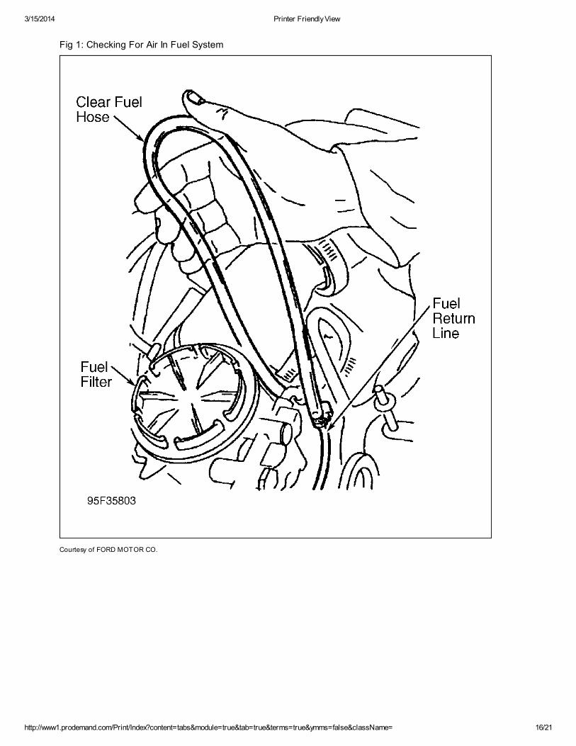
1. Disconnect fuel return hose at fuel filter. Install a clear fuel hose between fuel return hose and fuel
return hose fitting at fuel filter. Loop hose at a point higher than fuel filter. See Fig 1. While
observing fuel line, start and run engine for about 5 minutes. Fuel should be free of air.
2. If fuel is foamy, check for an air leak in fuel lines between fuel pump and fuel tank. Repair as
necessary. If no fuel flow exists, remove fuel regulator block, taking care not to damage "O" ring.
Inspect fuel return orifice screen for debris. Clean as necessary. See Fig 2.
Fig 1: Exploded View Of Fuel Regulator Valve (Vehicles With Electric Fuel Pump)
Courtesy of FORD MOTOR CO.
3/15/2014 Printer Friendly View
http://www1.prodemand.com/Print/Index?content=tabs&module=true&tab=true&terms=true&ymms=false&className= 16/21
Fig 1: Checking For Air In Fuel System
Courtesy of FORD MOTOR CO.

3/15/2014 Printer Friendly View
http://www1.prodemand.com/Print/Index?content=tabs&module=true&tab=true&terms=true&ymms=false&className= 17/21
ENGINE PERFORMANCE DIAGNOSIS > INJECTION CONTROL PRESSURE TESTS >
DIAGNOSTIC AIDS
Purpose of this test is to determine if engine oil is aerated and causing poor idle.
ENGINE PERFORMANCE DIAGNOSIS > INJECTION CONTROL PRESSURE TESTS > OIL
AERATION/POOR IDLE
1. Connect New Generation Star (NGS) scan tool to Data Link Connector (DLC). Turn A/C off. Using
scan tool, access ICP PID from PID/DATA monitor menu. See ADDITIONAL SYSTEM FUNCTIONS
in TESTS W/CODES - 7.3L DIESEL article.
2. Start engine and raise engine speed to 3400 RPM for 3 minutes. ICP PID reading should be 750-
1250 psi (5171-8619 kPa). If PID reading is not 750-1250 psi (5171-8619 kPa), change oil and
retest.
ENGINE PERFORMANCE DIAGNOSIS > INJECTION CONTROL PRESSURE TESTS > LOW
IDLE STABILITY (ICP PRESSURE)
1. Ensure engine is at normal operating temperature. Using scan tool, access ICP PID from
PID/DATA monitor menu. Start engine and allow it to idle.
Fig 2: Exploded View Of Fuel Regulator Block
Courtesy of FORD MOTOR CO.

3/15/2014 Printer Friendly View
http://www1.prodemand.com/Print/Index?content=tabs&module=true&tab=true&terms=true&ymms=false&className= 18/21
2. Check PID value. See ICP PID VALUES table. If PID reading is not as specified, or idle does not
stabilize, disconnect ICP sensor. Sensor is located at top left side of engine.
3. If idle is now stabilized, fault is in ICP sensor circuit. Perform CIRCUIT TEST DD in TESTS
W/CODES - 7.3L DIESEL article. If idle still does not stabilize, replace Injection Pressure Regulator
(IPR) and retest.
ICP PID VALUES
Application psi (kPa)
Federal vehicles 550-700
Calif. vehicles 400-600
ENGINE PERFORMANCE DIAGNOSIS > CRANKCASE PRESSURE TEST
1. Ensure engine is at normal operating temperature. Remove turbocharger inlet pipe ducting.
Remove inlet pipe and elbow that connects to air filter housing. Using cap provided in Engine
Pressure Tester (014-00761), block air filter housing outlet. Install a protective screen over
turbocharger inlet.
2. Screw Crankcase Orifice Restrictor (5631) and Crankcase Pressure Test Adapter (014-00743)
into oil fill cap hole. Connect adapter to pressure gauge (No. 4) at Engine Pressure Tester (014-
00761). Ensure gauge has been zeroed.
3. Observe gauge and raise engine speed to 3400 RPM for about 30 seconds. DO NOT block hole
at top of crankcase orifice restrictor. Pressure should be less than 4 in. H2O. If pressure is 4 in.
H2O or more, check engine mechanical condition (compression rings, cylinder bores, valves, etc.).
Repair as necessary.
ENGINE PERFORMANCE DIAGNOSIS > CHECK CYLINDER PERFORMANCE
If KOER CYLINDER CONTRIBUTION SELF-TEST under QUICK TEST in TESTS W/CODES - 7.3L DIESEL
article has been successfully completed previously, go to CHECK FOR EXHAUST RESTRICTION . If KOER
CYLINDER CONTRIBUTION SELF-TEST has not been completed, perform KOER CYLINDER
CONTRIBUTION SELF-TEST. Possible causes for failing this test are:
Broken compression rings.
Burnt or bent valve.
Bent push rods.
Bent connecting rods.
Damaged rocker arms.
Faulty fuel injector assembly.
ENGINE PERFORMANCE DIAGNOSIS > CHECK FOR EXHAUST RESTRICTION
Question: exhaust back pressure buterfly on turbo wont open
ENGINE PERFORMANCE DIAGNOSIS > CHECK FOR EXHAUST RESTRICTION >
DIAGNOSTIC AIDS
This is a visual inspection to determine if an exhaust restriction is contributing to a performance problem.

3/15/2014 Printer Friendly View
http://www1.prodemand.com/Print/Index?content=tabs&module=true&tab=true&terms=true&ymms=false&className= 19/21
1. Visually inspect exhaust system for damage. Repair as necessary. Start engine. Briefly raise
engine speed to 3500 RPM and inspect turbocharger exhaust backpressure butterfly bellcrank.
Ensure bellcrank is not closed. When bellcrank tang is against stop, valve is fully open. See
Figure.
2. Connect New Generation Star (NGS) scan tool to Data Link Connector (DLC). Turn A/C off. Using
scan tool, access EBP PID from PID/DATA monitor menu. See ADDITIONAL SYSTEM FUNCTIONS
in TESTS W/CODES - 7.3L DIESEL article.
3. Observe PID reading and briefly raise engine speed to 3500 RPM. If PID reading is 28 psi (193
kPa) or less, exhaust system is okay. If PID reading is more than 28 psi (193 kPa) exhaust is
restricted. Possible causes are:
1. Collapsed or plugged tailpipe.
2. Plugged or damaged muffler.
ENGINE PERFORMANCE DIAGNOSIS > BOOST PRESSURE TEST > DIAGNOSTIC AIDS
Perform this test to determine is engine can develop sufficient boost to obtain specific power. Possible
causes for low boost are:
Restricted intake or exhaust.
Pinched or disconnected MAP sensor hose.
Low fuel pressure.
Low injection control pressure.
Faulty injector driver module.
Faulty fuel injectors.
Faulty turbocharger.
Mechanical engine failure.
ENGINE PERFORMANCE DIAGNOSIS > BOOST PRESSURE TEST > WITH NEW
GENERATION STAR (NGS) SCAN TOOL
1. Ensure engine is at normal operating temperature. Connect NGS scan tool to Data Link Connector
(DLC). Turn A/C off. Using scan tool, access MGP PID from PID/DATA monitor menu. See
ADDITIONAL SYSTEM FUNCTIONS in TESTS W/CODES - 7.3L DIESEL article.
2. Observe PID reading and road test vehicle. Accelerate vehicle to achieve highest boost level
(2500-3000 RPM). Note PID reading. Boost level will level out after 3000 RPM. If PID reading is
15.5 psi (90 kPa) or more, boost level is okay. If boost level is not okay, see DIAGNOSTIC AIDS.
ENGINE PERFORMANCE DIAGNOSIS > BOOST PRESSURE TEST > WITHOUT NEW
GENERATION STAR (NGS) SCAN TOOL
1. Ensure engine is at normal operating temperature. Disconnect Manifold Absolute Pressure (MAP)
sensor hose at intake manifold. Install a "T" fitting between MAP sensor hose and hose nipple at
manifold. Connect a 0-30 psi (0-207 kPa) gauge to "T" fitting.
2. Ensure hose is long enough so gauge can be put inside cab of vehicle. Road test vehicle.
Observe pressure gauge and accelerate vehicle to achieve highest boost level (2500-3000 RPM).

3/15/2014 Printer Friendly View
http://www1.prodemand.com/Print/Index?content=tabs&module=true&tab=true&terms=true&ymms=false&className= 20/21
Note pressure reading. Boost level will level out after 3000 RPM. If boost pressure is 15.5 psi (90
kPa) or more, boost level is okay. If boost level is not okay, see DIAGNOSTIC AIDS.
TURBOCHARGER > VISUAL INSPECTION
Perform visual inspection for:
Damaged intake hoses.
Loose hose clamps.
Loose exhaust clamps.
Damaged turbocharger.
Restricted intake or exhaust.
If a problem is found, repair as necessary. If concern still exists, go to SYMPTOM DIAGNOSIS .
TURBOCHARGER > SYMPTOM DIAGNOSIS > NO BOOST
Wastegate actuator not functioning. See appropriate SELF-DIAGNOSTICS article.
Compress air intake hose collapsed. Repair or replace as required.
Compressor manifold hoses leaking. Tighten hose clamps.
Turbocharger turbine or compressor wheel damage. Replace turbocharger.
Turbocharger bearings seized. Replace turbocharger.
Clogged air cleaner element or restriction upstream of compressor. Repair or replace as
required.
TURBOCHARGER > SYMPTOM DIAGNOSIS > LACK OF POWER
Low compression. Repair as required.
Wastage actuator not functioning. See appropriate SELF-DIAGNOSTICS article.
Clogged air cleaner element or restriction upstream of compressor. Replace the air cleaner
element. Remove the restriction.
Insufficient fuel supply. Repair or replace as required.
TURBOCHARGER > SYMPTOM DIAGNOSIS > EXCESSIVE FUEL CONSUMPTION (BLACK
EXHAUST SMOKE)
High fuel pressure or pressure regulator. Repair as required. For more information, see
appropriate SELF-DIAGNOSTIC article.
Fuel return line plugged or kinked. Clean or replace as required.
Injectors leaking. Replace injectors.
Powertrain control module malfunctioning. See appropriate SEFL-DIAGNOSTICS article.
TURBOCHARGER > SYMPTOM DIAGNOSIS > EXCESSIVE OIL CONSUMPTION (BLUE,
GRAY OR WHITE EXHAUST SMOKE)
3/15/2014 Printer Friendly View
http://www1.prodemand.com/Print/Index?content=tabs&module=true&tab=true&terms=true&ymms=false&className= 21/21
Incorrect type or grade of oil. Drain and fill with specified oil.
Extended oil change intervals. Change oil as recommended.
Clogged air cleaner element or restriction upstream of compressor. Repair as required.
Engine wear (piston rings, valve guides). Repair as required.
Turbocharger oil seals leaking. See Turbocharger Internal Oil Leak Test under COMPONENT
TESTS.
Injector or injector "O" ring leaking. See appropriate SELF-DIAGNOSTICS article.
TURBOCHARGER > SYMPTOM DIAGNOSIS > NOISE OR VIBRATION
Leaks at turbocharger inlet and outlet connections. Repair as required.
Foreign object damage to turbine or compressor blades. Replace turbocharger.
Turbine bearing failure. Replace turbocharger.
TURBOCHARGER > SYMPTOM DIAGNOSIS > HIGH BOOST
Leak in exhaust system before muffler. Repair as required.
Malfunctioning wastegate. See appropriate SELF-DIAGNOSTIC article.
TURBOCHARGER > COMPONENT TESTS > TURBOCHARGER LEAK TEST
Check for loose connections or damage to air intake hoses and tubes.
Air leaks at the compressor manifold, intake manifold hoses or intake manifold covers can cause excessive
smoke, loss of engine power or a noise condition.
Exhaust leaks at the exhaust manifolds or in the turbine housing will also cause loss of engine power and a
noise condition.
Inspect turbocharger and components for loose connections or damage. Using a liquid soap on hose or
tube connections will aid in leak detection.
Exhaust leaks can usually be detected audibly or visually by a discoloration caused by escaping hot exhaust
gases.
TURBOCHARGER > COMPONENT TESTS > TURBOCHARGER INTERNAL OIL LEAK
TEST
Check the turbocharger compressor inlet for evidence of oil. If excessive oil is present, this indicates that the
failure is in the engine, not in the turbocharger; for additional information, see appropriate SELF-
DIAGNOSTICS article.
Check the turbocharger turbine outlet for evidence of oil. If oil is present in the outlet, remove the
turbocharger from the engine and examine the oil supply and return passages in the turbocharger pedestal
and engine block for restriction. If no restriction is found, replace the turbocharger.
TURBOCHARGER > COMPONENT TESTS > BEARING CLEARANCE CHECK
For bearing clearance check, see TURBOCHARGER OVERHAUL under FUEL SYSTEM in REMOVAL,
OVERHAUL & INSTALLATION - TRUCKS - DIESEL article.