hanger rod attachments - cooper · pdf filehanger rod attachments hanger rod structure...
TRANSCRIPT
HANGER ROD ATTACHMENTS
Hanger Rod Structure Attachments
Selection Procedure
1) Determine structure type to attach hanger rodA) ConcreteB) Wood BeamC) Structural Steel
2) Reference rod size and hanger rod load from Appendix 1 & 2.
3) Select a hanger rod attachment detail with a load capacity that meets the hanger rod load
General Notes For Concrete Attachments1) The “minimum embedment” values given on pages 40 - 43 provide the anchor capacity to reach the design loads
shown, but may be considered by the 1997 UBC to be “shallow” anchors (embedment less that 8 times the anchordiameter). Using “shallow” anchors may increase the design seismic force, depending on the building code used.As an alternative, consider using the following values to avoid “shallow anchor” issues:
Anchor Bolt Dia. “8x” Embedment3/8” 3” (76mm)1/2” 4” (101mm)5/8” 5” (127mm)3/4” 6” (152mm)
2) Size and number of expansion anchors is based on "without special inspection" values given in ICBO (InternationalConference of Building Officials) Report No. 4627 dated February 1, 2001, Hilti Kwik Bolt - II Carbon SteelAllowable Tension and Shear Values.
3) Other anchors may be used providing they are listed in an ICBO ES Evaluation Report, which was tested inaccordance with AC01, including the seismic qualification tests of AC01 Section 5.6. These values must meet orexceed the values provided in ICBO Report No. 4627, and are approved by the structural engineer of record.OSHPD change order is required for California hospitals.
4) For California hospitals and schools, 50% of the expansion type anchor (alternate anchors in a group) shall beproof tested per Appendix 3. Other projects may have similar requirements, check local codes and ordinances.
5) Cast in place concrete anchors require special inspection as indicated in the building code for the localjurisdiction.
6) When slab thickness is less than the minimum allowable, but in excess of the minimum anchor embedment, a thrubolt approach may be used if approved by the site engineer.
7) When installing drill-in anchors in existing non-prestressed reinforced concrete, use care and caution to avoidcutting or damaging the existing reinforcing bars. When installing them into existing prestressed concrete (pre-orpost-tensioned), locate the prestressed tendons by using a non-destructive method prior to installation. Exerciseextreme care and caution to avoid cutting or damaging the tendons during installation. Maintain a minimumclearance of 1 inch (25mm) between the reinforcement and the drilled-in anchor.
COOPER B-Line
Raafat S. AboulhosnStructural Engineer S 3913
509 West Monroe StreetHighland, Illinois 62249Phone: 618-654-2184Fax: 618-654-1917
Date:
12 - 9 - 02
Page No.
39
Sheet Number:
of
**SRS2002-OSpg.26-39 (11/02) N 1/3/03 4:43 PM Page 14
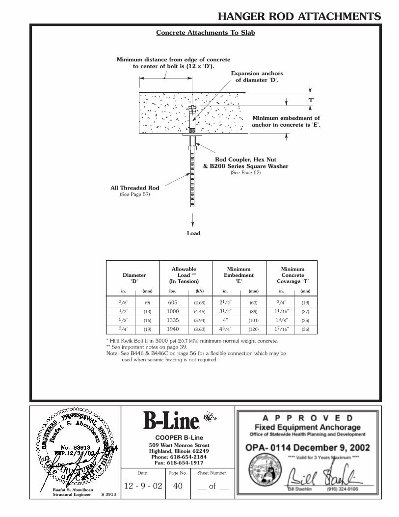
HANGER ROD ATTACHMENTSConcrete Attachments To Slab
* Hilti Kwik Bolt II in 3000 psi (20.7 MPa) minimum normal weight concrete.** See important notes on page 39.Note: See B446 & B446C on page 56 for a flexible connection which may be
used when seismic bracing is not required.
Allowable Minimum MinimumDiameter Load ** Embedment Concrete
'D' (In Tension) 'E' Coverage ‘T’
in. (mm) lbs. (kN) in. (mm) in. (mm)
3/8" (9) 605 (2.69) 21/2" (63) 3/4" (19)
1/2" (13) 1000 (4.45) 31/2" (89) 11/16" (27)
5/8" (16) 1335 (5.94) 4" (101) 13/8" (35)
3/4" (19) 1940 (8.63) 43/4" (120) 17/16" (36)
Rod Coupler, Hex Nut& B200 Series Square Washer
(See Page 62)
All Threaded Rod(See Page 57)
Load
Minimum distance from edge of concreteto center of bolt is (12 x 'D').
Minimum embedment ofanchor in concrete is 'E'.
‘T’
Expansion anchorsof diameter 'D'.
COOPER B-Line
Raafat S. AboulhosnStructural Engineer S 3913
509 West Monroe StreetHighland, Illinois 62249Phone: 618-654-2184Fax: 618-654-1917
Date:
12 - 9 - 02
Page No.
40
Sheet Number:
of
**SRS2002-OSpg.40-53 (11/02) N 1/3/03 5:12 PM Page 1
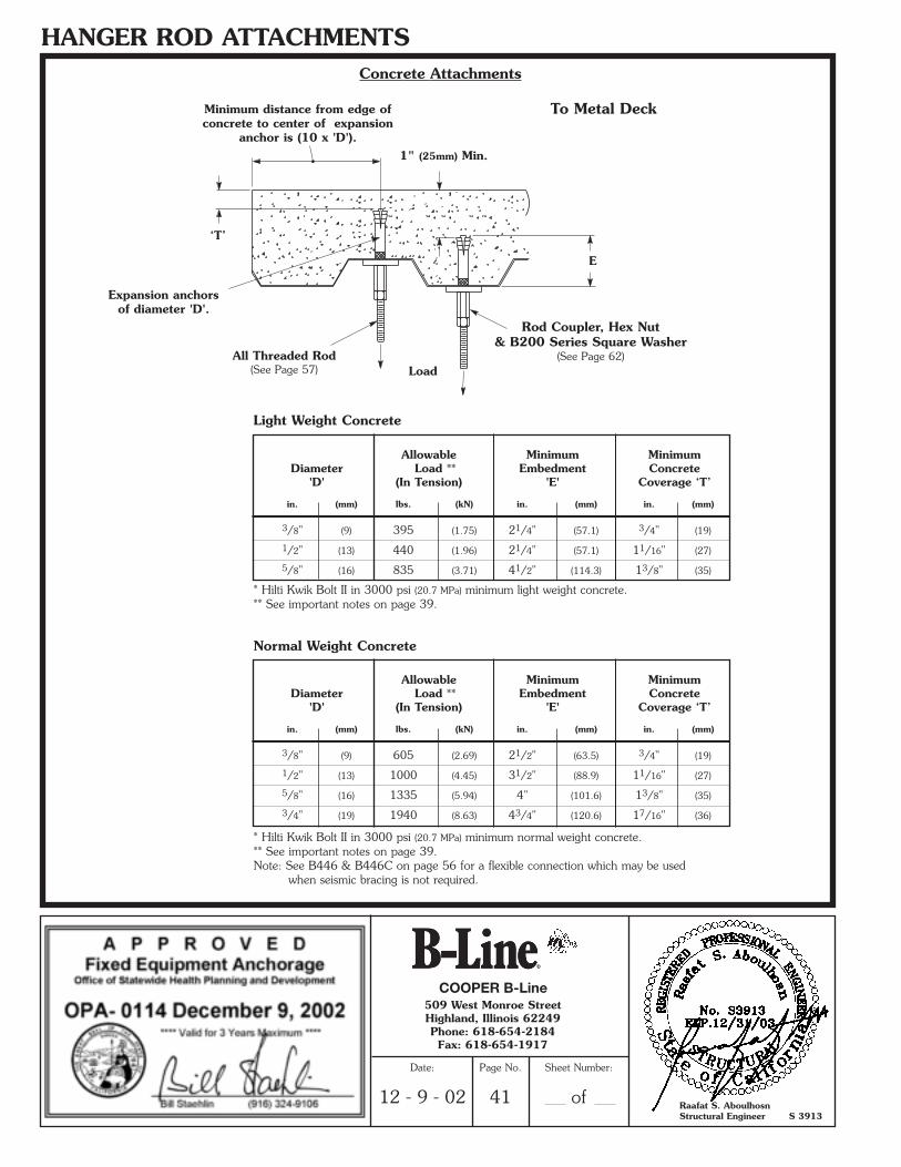
HANGER ROD ATTACHMENTSConcrete Attachments
To Metal Deck
Load
Rod Coupler, Hex Nut& B200 Series Square Washer
(See Page 62)All Threaded Rod(See Page 57)
Expansion anchorsof diameter 'D'.
E
‘T’
1" (25mm) Min.
Minimum distance from edge ofconcrete to center of expansion
anchor is (10 x 'D').
* Hilti Kwik Bolt II in 3000 psi (20.7 MPa) minimum normal weight concrete.** See important notes on page 39.Note: See B446 & B446C on page 56 for a flexible connection which may be used
when seismic bracing is not required.
* Hilti Kwik Bolt II in 3000 psi (20.7 MPa) minimum light weight concrete.** See important notes on page 39.
Light Weight Concrete
Normal Weight Concrete
Allowable Minimum MinimumDiameter Load ** Embedment Concrete
'D' (In Tension) 'E' Coverage ‘T’
in. (mm) lbs. (kN) in. (mm) in. (mm)
3/8" (9) 395 (1.75) 21/4" (57.1) 3/4" (19)
1/2" (13) 440 (1.96) 21/4" (57.1) 11/16" (27)
5/8" (16) 835 (3.71) 41/2" (114.3) 13/8" (35)
Allowable Minimum MinimumDiameter Load ** Embedment Concrete
'D' (In Tension) 'E' Coverage ‘T’
in. (mm) lbs. (kN) in. (mm) in. (mm)
3/8" (9) 605 (2.69) 21/2" (63.5) 3/4" (19)
1/2" (13) 1000 (4.45) 31/2" (88.9) 11/16" (27)
5/8" (16) 1335 (5.94) 4" (101.6) 13/8" (35)
3/4" (19) 1940 (8.63) 43/4" (120.6) 17/16" (36)
COOPER B-Line
Raafat S. AboulhosnStructural Engineer S 3913
509 West Monroe StreetHighland, Illinois 62249Phone: 618-654-2184Fax: 618-654-1917
Date:
12 - 9 - 02
Page No.
41
Sheet Number:
of
**SRS2002-OSpg.40-53 (11/02) N 1/3/03 5:13 PM Page 2
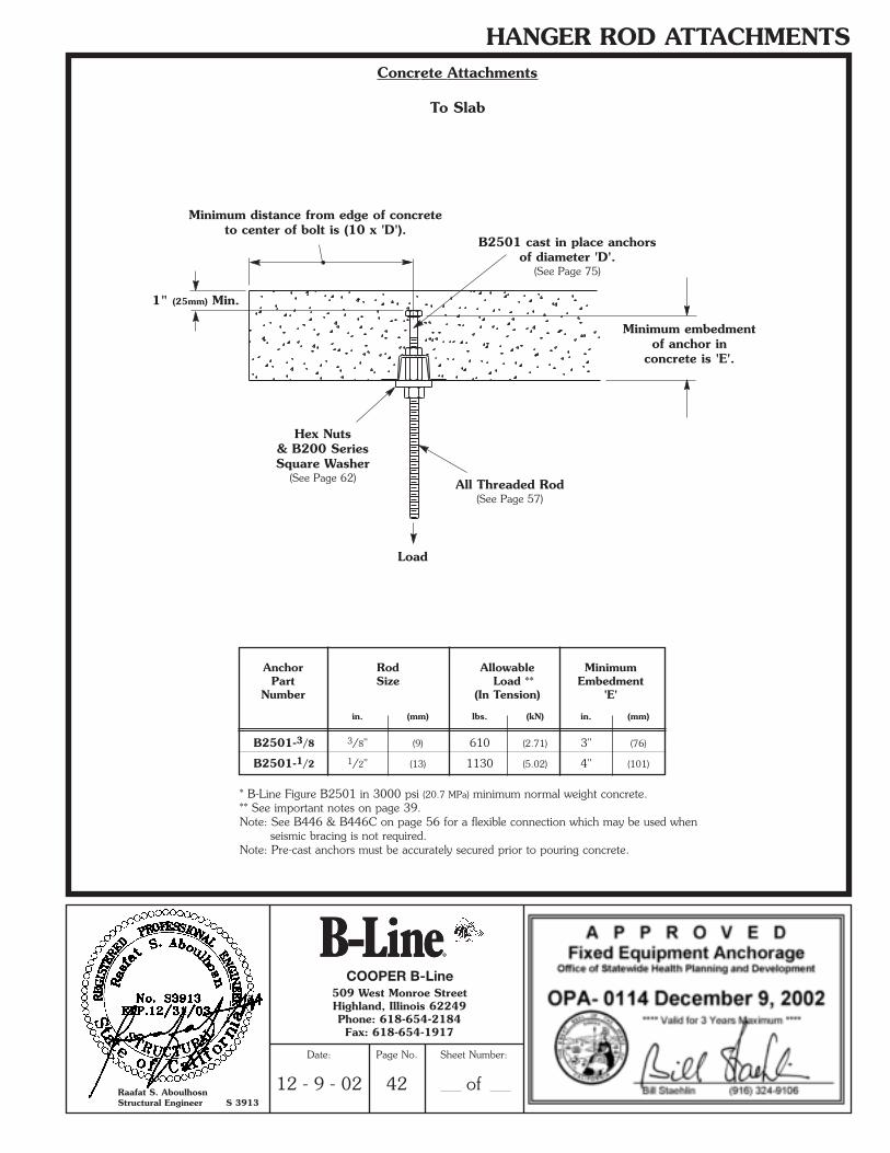
HANGER ROD ATTACHMENTSConcrete Attachments
To Slab
Load
B2501 cast in place anchorsof diameter 'D'.
(See Page 75)
* B-Line Figure B2501 in 3000 psi (20.7 MPa) minimum normal weight concrete.** See important notes on page 39.Note: See B446 & B446C on page 56 for a flexible connection which may be used when
seismic bracing is not required.Note: Pre-cast anchors must be accurately secured prior to pouring concrete.
Anchor Rod Allowable MinimumPart Size Load ** Embedment
Number (In Tension) 'E'
in. (mm) lbs. (kN) in. (mm)
B2501-3/8 3/8" (9) 610 (2.71) 3" (76)
B2501-1/2 1/2" (13) 1130 (5.02) 4" (101)
Minimum distance from edge of concreteto center of bolt is (10 x 'D').
Minimum embedmentof anchor in
concrete is 'E'.
Hex Nuts& B200 SeriesSquare Washer
(See Page 62) All Threaded Rod(See Page 57)
1" (25mm) Min.
COOPER B-Line
Raafat S. AboulhosnStructural Engineer S 3913
509 West Monroe StreetHighland, Illinois 62249Phone: 618-654-2184Fax: 618-654-1917
Date:
12 - 9 - 02
Page No.
42
Sheet Number:
of
**SRS2002-OSpg.40-53 (11/02) N 1/3/03 5:13 PM Page 3
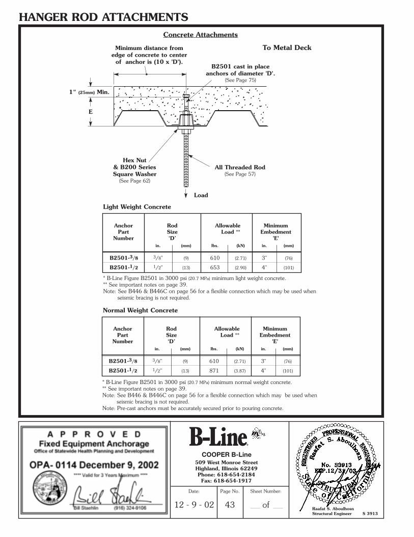
HANGER ROD ATTACHMENTSConcrete Attachments
B2501 cast in placeanchors of diameter 'D'.
(See Page 75)
Load
To Metal Deck
E
Hex Nut& B200 SeriesSquare Washer
(See Page 62)
All Threaded Rod(See Page 57)
* B-Line Figure B2501 in 3000 psi (20.7 MPa) minimum normal weight concrete.** See important notes on page 39.Note: See B446 & B446C on page 56 for a flexible connection which may be used when
seismic bracing is not required.Note: Pre-cast anchors must be accurately secured prior to pouring concrete.
Anchor Rod Allowable MinimumPart Size Load ** Embedment
Number ‘D’ 'E'in. (mm) lbs. (kN) in. (mm)
B2501-3/8 3/8" (9) 610 (2.71) 3" (76)
B2501-1/2 1/2" (13) 871 (3.87) 4" (101)
* B-Line Figure B2501 in 3000 psi (20.7 MPa) minimum light weight concrete.** See important notes on page 39.Note: See B446 & B446C on page 56 for a flexible connection which may be used when
seismic bracing is not required.
Anchor Rod Allowable MinimumPart Size Load ** Embedment
Number ‘D’ 'E'in. (mm) lbs. (kN) in. (mm)
B2501-3/8 3/8" (9) 610 (2.71) 3" (76)
B2501-1/2 1/2" (13) 653 (2.90) 4" (101)
1" (25mm) Min.
Minimum distance fromedge of concrete to center
of anchor is (10 x 'D').
Normal Weight Concrete
Light Weight Concrete
COOPER B-Line
Raafat S. AboulhosnStructural Engineer S 3913
509 West Monroe StreetHighland, Illinois 62249Phone: 618-654-2184Fax: 618-654-1917
Date:
12 - 9 - 02
Page No.
43
Sheet Number:
of
**SRS2002-OSpg.40-53 (11/02) N 1/3/03 5:13 PM Page 4
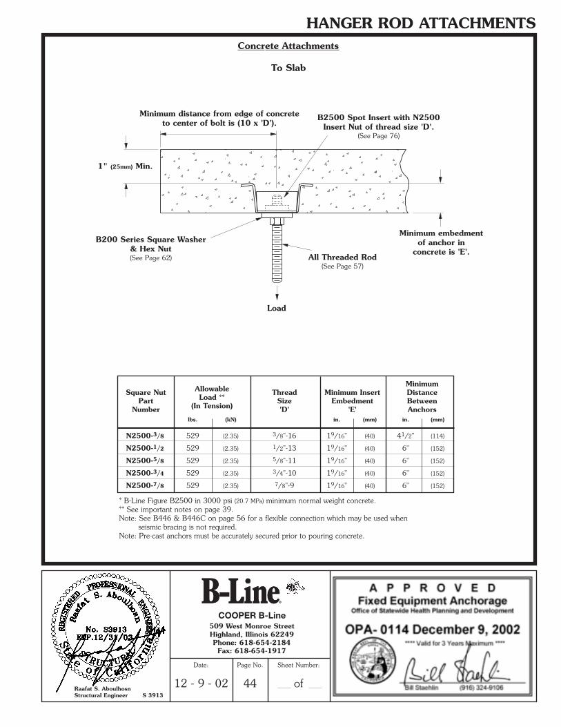
HANGER ROD ATTACHMENTSConcrete Attachments
To Slab
Load
B2500 Spot Insert with N2500Insert Nut of thread size 'D'.
(See Page 76)
* B-Line Figure B2500 in 3000 psi (20.7 MPa) minimum normal weight concrete.** See important notes on page 39.Note: See B446 & B446C on page 56 for a flexible connection which may be used when
seismic bracing is not required.Note: Pre-cast anchors must be accurately secured prior to pouring concrete.
Minimum distance from edge of concreteto center of bolt is (10 x 'D').
Minimum embedmentof anchor in
concrete is 'E'.
B200 Series Square Washer& Hex Nut(See Page 62) All Threaded Rod
(See Page 57)
1" (25mm) Min.
MinimumSquare Nut Allowable Thread Minimum Insert Distance
Part Load ** Size Embedment BetweenNumber (In Tension) 'D' 'E' Anchors
lbs. (kN) in. (mm) in. (mm)
N2500-3/8 529 (2.35) 3/8"-16 19/16" (40) 41/2" (114)
N2500-1/2 529 (2.35) 1/2"-13 19/16" (40) 6" (152)
N2500-5/8 529 (2.35) 5/8"-11 19/16" (40) 6" (152)
N2500-3/4 529 (2.35) 3/4"-10 19/16" (40) 6" (152)
N2500-7/8 529 (2.35) 7/8"-9 19/16" (40) 6" (152)
COOPER B-Line
Raafat S. AboulhosnStructural Engineer S 3913
509 West Monroe StreetHighland, Illinois 62249Phone: 618-654-2184Fax: 618-654-1917
Date:
12 - 9 - 02
Page No.
44
Sheet Number:
of
**SRS2002-OSpg.40-53 (11/02) N 1/3/03 5:13 PM Page 5
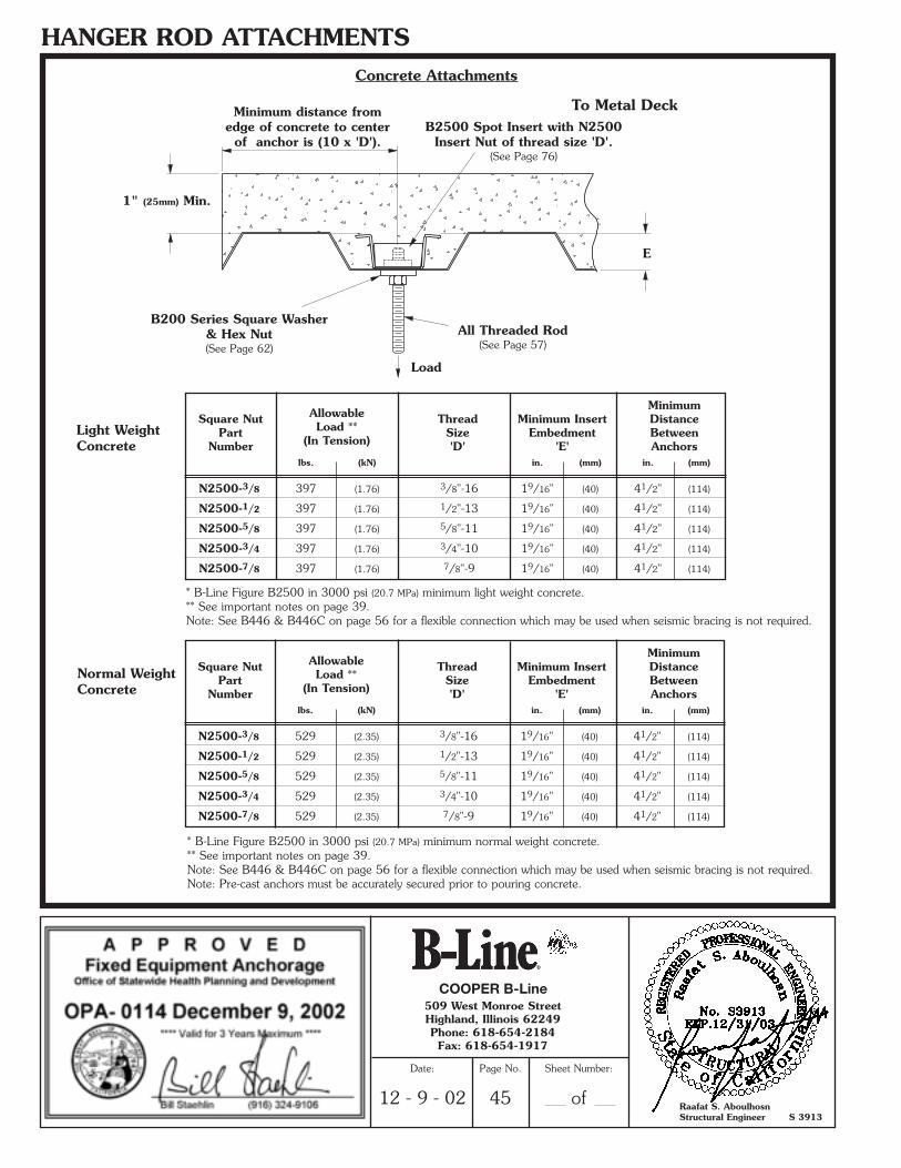
HANGER ROD ATTACHMENTSConcrete Attachments
Load
To Metal Deck
E
All Threaded Rod(See Page 57)
* B-Line Figure B2500 in 3000 psi (20.7 MPa) minimum normal weight concrete.** See important notes on page 39.Note: See B446 & B446C on page 56 for a flexible connection which may be used when seismic bracing is not required.Note: Pre-cast anchors must be accurately secured prior to pouring concrete.
* B-Line Figure B2500 in 3000 psi (20.7 MPa) minimum light weight concrete.** See important notes on page 39.Note: See B446 & B446C on page 56 for a flexible connection which may be used when seismic bracing is not required.
1" (25mm) Min.
Minimum distance fromedge of concrete to center
of anchor is (10 x 'D').
Normal WeightConcrete
Light WeightConcrete
MinimumSquare Nut Allowable Thread Minimum Insert Distance
Part Load ** Size Embedment BetweenNumber (In Tension) 'D' 'E' Anchors
lbs. (kN) in. (mm) in. (mm)
N2500-3/8 397 (1.76) 3/8"-16 19/16" (40) 41/2" (114)
N2500-1/2 397 (1.76) 1/2"-13 19/16" (40) 41/2" (114)
N2500-5/8 397 (1.76) 5/8"-11 19/16" (40) 41/2" (114)
N2500-3/4 397 (1.76) 3/4"-10 19/16" (40) 41/2" (114)
N2500-7/8 397 (1.76) 7/8"-9 19/16" (40) 41/2" (114)
MinimumSquare Nut Allowable Thread Minimum Insert Distance
Part Load ** Size Embedment BetweenNumber (In Tension) 'D' 'E' Anchors
lbs. (kN) in. (mm) in. (mm)
N2500-3/8 529 (2.35) 3/8"-16 19/16" (40) 41/2" (114)
N2500-1/2 529 (2.35) 1/2"-13 19/16" (40) 41/2" (114)
N2500-5/8 529 (2.35) 5/8"-11 19/16" (40) 41/2" (114)
N2500-3/4 529 (2.35) 3/4"-10 19/16" (40) 41/2" (114)
N2500-7/8 529 (2.35) 7/8"-9 19/16" (40) 41/2" (114)
B200 Series Square Washer& Hex Nut(See Page 62)
B2500 Spot Insert with N2500Insert Nut of thread size 'D'.
(See Page 76)
COOPER B-Line
Raafat S. AboulhosnStructural Engineer S 3913
509 West Monroe StreetHighland, Illinois 62249Phone: 618-654-2184Fax: 618-654-1917
Date:
12 - 9 - 02
Page No.
45
Sheet Number:
of
**SRS2002-OSpg.40-53 (11/02) N 1/3/03 5:13 PM Page 6

HANGER ROD ATTACHMENTSConcrete Attachments
To Slab
B32I-12 or strongerConcrete Insert attached to
concrete structure(See Pages 77 & 78)
Note: Reduce load by 50%when connection is
within 2” (51mm) from theend of the insert.
Load
B-Line Channel Nut(See Page 61)
B200 Series SquareWasher, Hex Nut
(See Page 62)
All Threaded Rod(See Page 57)
ChannelNut Allowable
ATR Part Load
Size Number (In Tension)
lbs. (kN)
3/8"-16 N228 Series 610 (2.71)
1/2"-13 N225 Series 1130 (5.02)
5/8"-11 N255 Series 1810 (8.05)
3/4"-10 N275 Series 2000 (8.89)
7/8"-9 N278 Series 2000 (8.89)
Note: See B446 & B446C on page 56 for a flexible connection which may be used when seismic bracing is not required.
Note: Pre-cast anchors must be accurately secured prior to pouring concrete.
COOPER B-Line
Raafat S. AboulhosnStructural Engineer S 3913
509 West Monroe StreetHighland, Illinois 62249Phone: 618-654-2184Fax: 618-654-1917
Date:
12 - 9 - 02
Page No.
46
Sheet Number:
of
**SRS2002-OSpg.40-53 (11/02) N 1/3/03 5:13 PM Page 7
HANGER ROD ATTACHMENTS
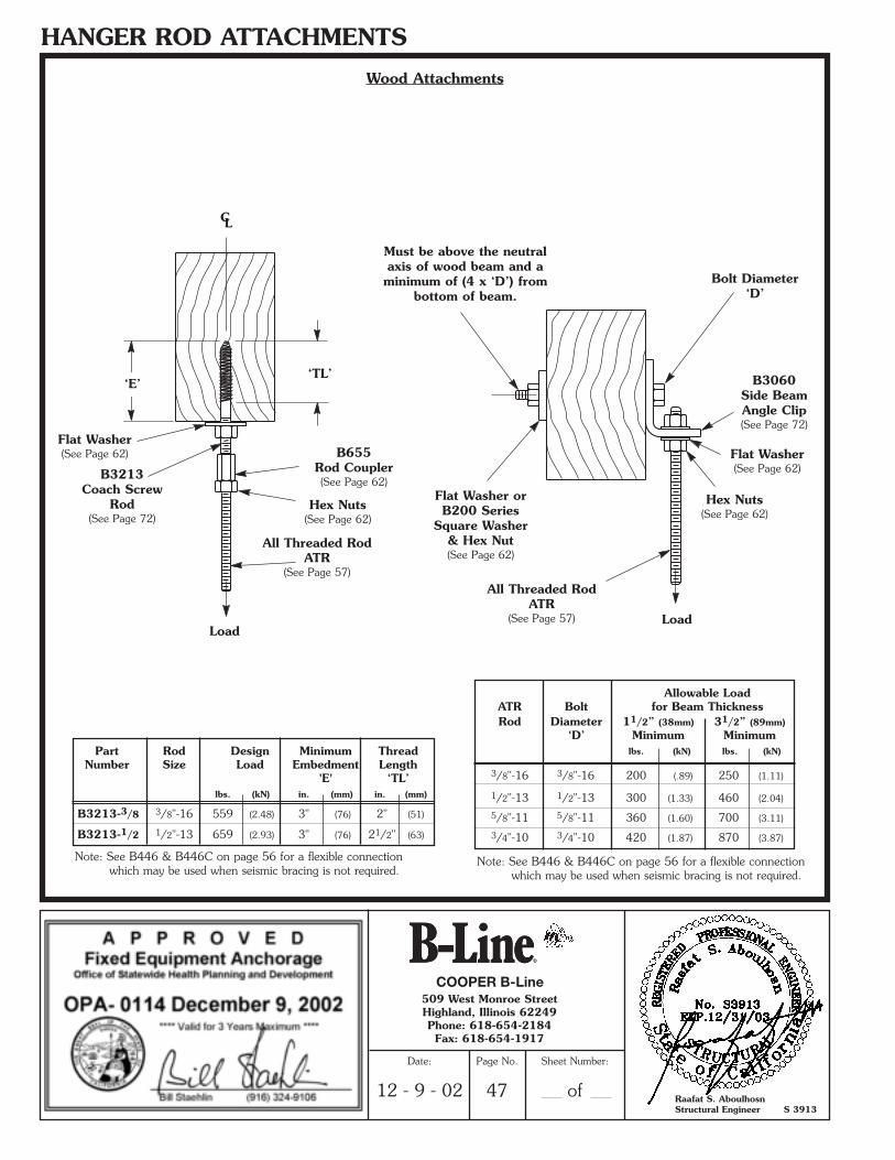
Part Rod Design Minimum ThreadNumber Size Load Embedment Length
'E' ‘TL’lbs. (kN) in. (mm) in. (mm)
B3213-3/8 3/8"-16 559 (2.48) 3" (76) 2" (51)
B3213-1/2 1/2"-13 659 (2.93) 3" (76) 21/2" (63)
Allowable LoadATR Bolt for Beam ThicknessRod Diameter 11/2” (38mm) 31/2” (89mm)
‘D’ Minimum Minimumlbs. (kN) lbs. (kN)
3/8"-16 3/8"-16 200 (.89) 250 (1.11)
1/2"-13 1/2"-13 300 (1.33) 460 (2.04)
5/8"-11 5/8"-11 360 (1.60) 700 (3.11)
3/4"-10 3/4"-10 420 (1.87) 870 (3.87)
Wood Attachments
Load
‘E’‘TL’
CL
B3213Coach Screw
Rod(See Page 72)
B655Rod Coupler(See Page 62)
Flat Washer(See Page 62)
Hex Nuts(See Page 62)
All Threaded RodATR
(See Page 57)
Load
B3060Side BeamAngle Clip(See Page 72)
Bolt Diameter‘D’
Hex Nuts(See Page 62)
All Threaded RodATR
(See Page 57)
Flat Washer orB200 Series
Square Washer& Hex Nut(See Page 62)
Must be above the neutralaxis of wood beam and aminimum of (4 x ‘D’) from
bottom of beam.
Note: See B446 & B446C on page 56 for a flexible connection which may be used when seismic bracing is not required.
Note: See B446 & B446C on page 56 for a flexible connection which may be used when seismic bracing is not required.
Flat Washer(See Page 62)
COOPER B-Line
Raafat S. AboulhosnStructural Engineer S 3913
509 West Monroe StreetHighland, Illinois 62249Phone: 618-654-2184Fax: 618-654-1917
Date:
12 - 9 - 02
Page No.
47
Sheet Number:
of
**SRS2002-OSpg.40-53 (11/02) N 1/3/03 5:13 PM Page 8
HANGER ROD ATTACHMENTS
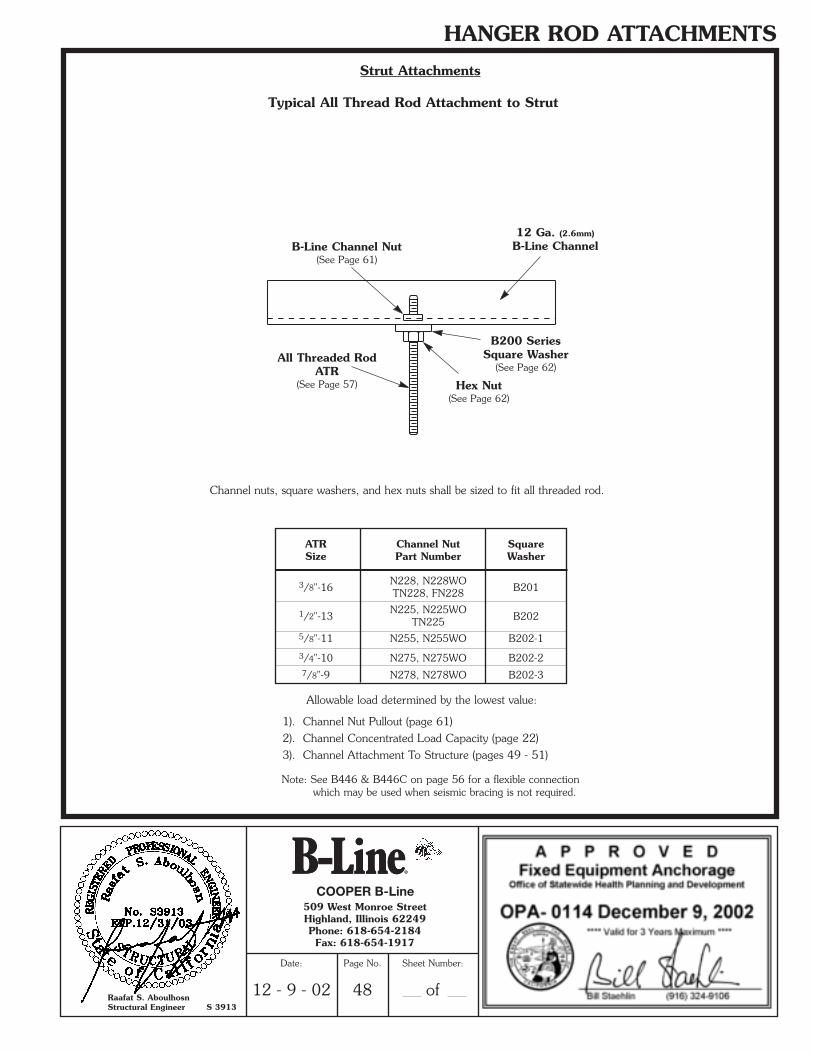
Strut Attachments
Typical All Thread Rod Attachment to Strut
B200 SeriesSquare Washer
(See Page 62)
Hex Nut(See Page 62)
B-Line Channel Nut(See Page 61)
12 Ga. (2.6mm)
B-Line Channel
All Threaded RodATR
(See Page 57)
Channel nuts, square washers, and hex nuts shall be sized to fit all threaded rod.
Allowable load determined by the lowest value:
1). Channel Nut Pullout (page 61)2). Channel Concentrated Load Capacity (page 22)3). Channel Attachment To Structure (pages 49 - 51)
ATR Channel Nut SquareSize Part Number Washer
3/8"-16N228, N228WO
B201TN228, FN228
1/2"-13N225, N225WO
B202TN2255/8"-11 N255, N255WO B202-1
3/4"-10 N275, N275WO B202-27/8"-9 N278, N278WO B202-3
Note: See B446 & B446C on page 56 for a flexible connection which may be used when seismic bracing is not required.
COOPER B-Line
Raafat S. AboulhosnStructural Engineer S 3913
509 West Monroe StreetHighland, Illinois 62249Phone: 618-654-2184Fax: 618-654-1917
Date:
12 - 9 - 02
Page No.
48
Sheet Number:
of
**SRS2002-OSpg.40-53 (11/02) N 1/3/03 5:13 PM Page 9
HANGER ROD ATTACHMENTS & APPROVED COMPONENTS
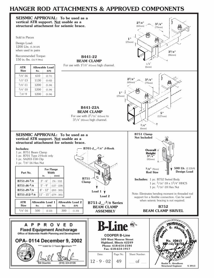
Sold in Pieces
Design Load:1200 Lbs. (5.34 kN)
when used in pairs
Recommended Torque:150 in.-lbs. (16.9 N•m)
1/4"(6mm)
33/8"(86mm)
31/8"(79mm)
23/8"(60mm)
1"(25mm)
B441-22BEAM CLAMP
For use with 15/8" (41mm) high channel.
B441-22ABEAM CLAMP
For use with 27/16" (62mm) to31/4" (82mm) high channel.
1/4"(6mm)
5"(127mm)
1"(25mm)
23/8"(60mm)
31/8"(79mm)
3/8" (9mm)Rod Size
B751-J__-3/8 SeriesBEAM CLAMP
ASSEMBLYB752
BEAM CLAMP SWIVEL
For FlangePart No. Width
in. (mm)
B751-J4-3/8 3" - 6" (76 - 152)
B751-J6-3/8 5" - 9" (127 - 228)
B751-J9-3/8 8" - 12" (203 - 305)
B751-J12-3/8 11" - 15" (279 - 381)
B751Clamp
Load 1
Load 2
B701-J__-3/8" J-Hook
Note: Eliminates bending moment in threaded rodsupport for a flexible connection. Can be used
when seismic bracing is not required.
B751 ClampNot Included
SEISMIC APPROVAL: To be used as avertical ATR support. Not usable as astructural attachment for seismic brace.
SEISMIC APPROVAL: To be used as avertical ATR support. Not usable as astructural attachment for seismic brace.
Includes:1 pc. B751 Beam Clamp1 pc. B701 Type J-Hook only1 pc. SA203-158 Clip1 pc. 3/8"-16 Hex Nut
Includes: 1 pc. B752 Swivel Body1 pc. 5/16"-18 x 13/4" HHCS1 pc. 5/16"-18 Hex Nut
ATR Allowable LoadSize lbs. (kN)
3/8"-16 610 (2.71)
1/2"-13 1130 (5.02)
5/8"-11 1200 (5.34)
3/4"-10 1200 (5.34)
7/8"-9 1200 (5.34)
ATR Allowable Load 1 Allowable Load 2Size lbs. (kN) lbs. (kN)
3/8"-16 500 (2.22) 300 (1.33)
500 Lb. (2.22kN)Design Load
OverallHeight31/4” (82mm)
COOPER B-Line
Raafat S. AboulhosnStructural Engineer S 3913
509 West Monroe StreetHighland, Illinois 62249Phone: 618-654-2184Fax: 618-654-1917
Date:
12 - 9 - 02
Page No.
49
Sheet Number:
of
**SRS2002-OSpg.40-53 (11/02) N 1/3/03 5:13 PM Page 10
HANGER ROD ATTACHMENTS & APPROVED COMPONENTS
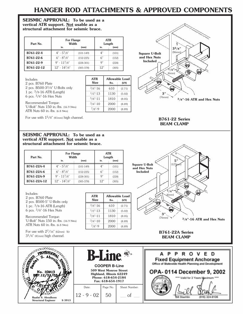
Includes:2 pcs. B760 Plate2 pcs. B500-33/8" U-Bolts only1 pc. 3/8-16 ATR (Length)6 pcs. 3/8"-16 Hex Nuts
Recommended Torque:'U-Bolt" Nuts 150 in.-lbs. (16.9 N•m)
ATR Nuts 60 in.-lbs. (6.8 N•m)
For use with 15/8" (41mm) high channel.
3"(76mm)
1/4"(6mm)
33/8"(86mm)
3/8"-16 ATR and Hex Nuts
B761-22 SeriesBEAM CLAMP
For Flange ATRPart No. Width Length
in. (mm) in. (mm)
B761-22-4 4" - 57/8" (101-149) 4" (101)
B761-22-6 6" - 87/8" (152-225) 6" (152)
B761-22-9 9" - 117/8" (228-301) 9" (228)
B761-22-12 12" - 147/8" (305-378) 12" (305)
Includes:2 pcs. B760 Plate2 pcs. B500-5" U-Bolts only1 pc. 3/8-16 ATR (Length)6 pcs. 3/8"-16 Hex Nuts
Recommended Torque:'U-Bolt" Nuts 150 in.-lbs. (16.9 N•m)
ATR Nuts 60 in.-lbs. (6.8 N•m)
For use with 27/16" (62mm) to31/4" (41mm) high channel.
3"(76mm)
1/4"(6mm)
5"(127mm)
3/8"-16 ATR and Hex Nuts
B761-22A SeriesBEAM CLAMP
Square U-Boltand Hex Nuts
Included
Square U-Boltand Hex Nuts
Included
SEISMIC APPROVAL: To be used as avertical ATR support. Not usable as astructural attachment for seismic brace.
SEISMIC APPROVAL: To be used as avertical ATR support. Not usable as astructural attachment for seismic brace.
ATR Allowable LoadSize lbs. (kN)
3/8"-16 610 (2.71)
1/2"-13 1130 (5.02)
5/8"-11 1810 (8.05)
3/4"-10 2000 (8.89)
7/8"-9 2000 (8.89)
ATR Allowable LoadSize lbs. (kN)
3/8"-16 610 (2.71)
1/2"-13 1130 (5.02)
5/8"-11 1810 (8.05)
3/4"-10 2000 (8.89)
7/8"-9 2000 (8.89)
For Flange ATRPart No. Width Length
in. (mm) in. (mm)
B761-22A-4 4" - 57/8" (101-149) 4" (101)
B761-22A-6 6" - 87/8" (152-225) 6" (152)
B761-22A-9 9" - 117/8" (228-301) 9" (228)
B761-22A-12 12" - 147/8" (305-378) 12" (305)
COOPER B-Line
Raafat S. AboulhosnStructural Engineer S 3913
509 West Monroe StreetHighland, Illinois 62249Phone: 618-654-2184Fax: 618-654-1917
Date:
12 - 9 - 02
Page No.
50
Sheet Number:
of
**SRS2002-OSpg.40-53 (11/02) N 1/3/03 5:13 PM Page 11
HANGER ROD ATTACHMENTS & APPROVED COMPONENTS
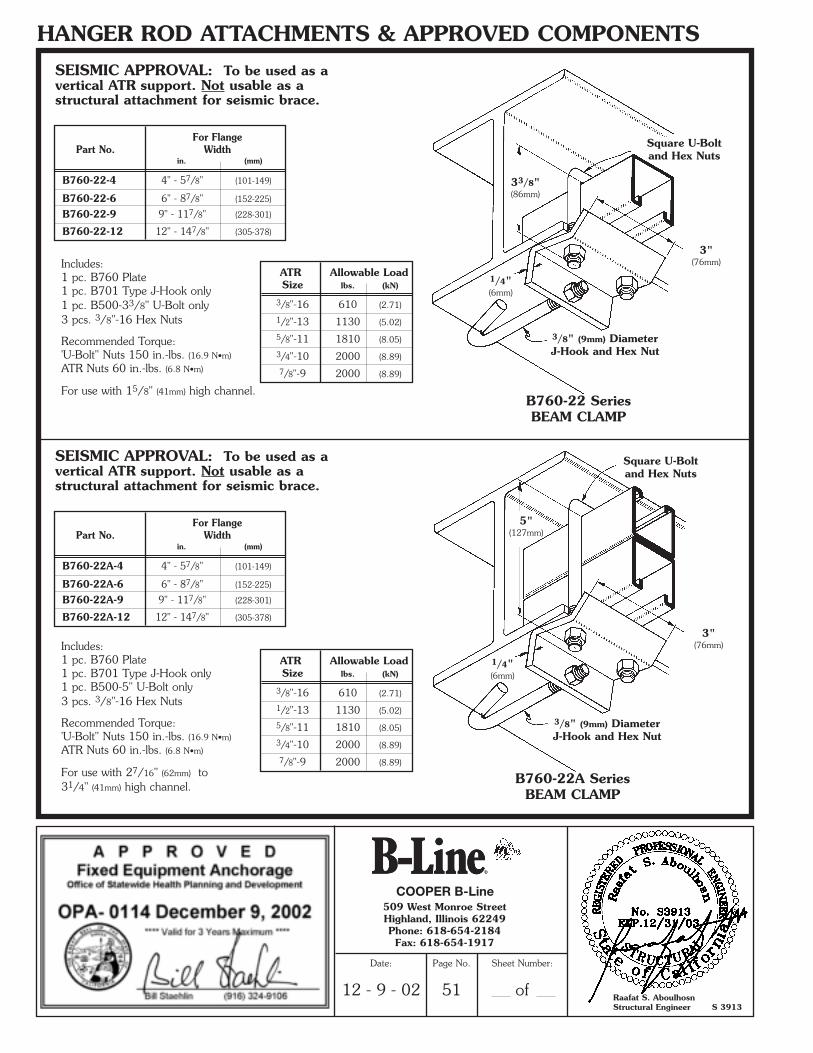
For FlangePart No. Width
in. (mm)
B760-22-4 4" - 57/8" (101-149)
B760-22-6 6" - 87/8" (152-225)
B760-22-9 9" - 117/8" (228-301)
B760-22-12 12" - 147/8" (305-378)
For FlangePart No. Width
in. (mm)
B760-22A-4 4" - 57/8" (101-149)
B760-22A-6 6" - 87/8" (152-225)
B760-22A-9 9" - 117/8" (228-301)
B760-22A-12 12" - 147/8" (305-378)
Includes:1 pc. B760 Plate1 pc. B701 Type J-Hook only1 pc. B500-33/8" U-Bolt only3 pcs. 3/8"-16 Hex Nuts
Recommended Torque:'U-Bolt" Nuts 150 in.-lbs. (16.9 N•m)
ATR Nuts 60 in.-lbs. (6.8 N•m)
For use with 15/8" (41mm) high channel.
3"(76mm)
1/4"(6mm)
33/8"(86mm)
3/8" (9mm) DiameterJ-Hook and Hex Nut
Square U-Boltand Hex Nuts
B760-22 SeriesBEAM CLAMP
Includes:1 pc. B760 Plate1 pc. B701 Type J-Hook only1 pc. B500-5" U-Bolt only3 pcs. 3/8"-16 Hex Nuts
Recommended Torque:'U-Bolt" Nuts 150 in.-lbs. (16.9 N•m)
ATR Nuts 60 in.-lbs. (6.8 N•m)
For use with 27/16" (62mm) to31/4" (41mm) high channel.
3"(76mm)
1/4"(6mm)
5"(127mm)
B760-22A SeriesBEAM CLAMP
3/8" (9mm) DiameterJ-Hook and Hex Nut
Square U-Boltand Hex Nuts
SEISMIC APPROVAL: To be used as avertical ATR support. Not usable as astructural attachment for seismic brace.
SEISMIC APPROVAL: To be used as avertical ATR support. Not usable as astructural attachment for seismic brace.
ATR Allowable LoadSize lbs. (kN)
3/8"-16 610 (2.71)
1/2"-13 1130 (5.02)
5/8"-11 1810 (8.05)
3/4"-10 2000 (8.89)
7/8"-9 2000 (8.89)
ATR Allowable LoadSize lbs. (kN)
3/8"-16 610 (2.71)
1/2"-13 1130 (5.02)
5/8"-11 1810 (8.05)
3/4"-10 2000 (8.89)
7/8"-9 2000 (8.89)
COOPER B-Line
Raafat S. AboulhosnStructural Engineer S 3913
509 West Monroe StreetHighland, Illinois 62249Phone: 618-654-2184Fax: 618-654-1917
Date:
12 - 9 - 02
Page No.
51
Sheet Number:
of
**SRS2002-OSpg.40-53 (11/02) N 1/3/03 5:13 PM Page 12
HANGER ROD ATTACHMENTS & APPROVED COMPONENTS
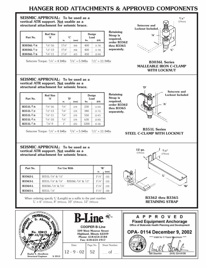
Setscrew Torque: 1/4” = 4 ft•lbs 3/8” = 5 ft•lbs 1/2” = 11 ft•lbs
'A'
Setscrew andLocknut Included
3/4"(19mm)
B3036L SeriesMALLEABLE IRON C-CLAMP
WITH LOCKNUT
Rod Size DesignPart No. 'A' 'C' Load
in. (mm) lbs. (kN)
B3036L-3/8 3/8"-16 13/4" (44) 400 (1.78)
B3036L-1/2 1/2"-13 13/4" (44) 400 (1.78)
B3036L-5/8 5/8"-11 17/8" (47) 450 (2.00)
'C'
'A'
Setscrew andLocknut Included
B351L SeriesSTEEL C-CLAMP WITH LOCKNUT
Rod Size DesignPart No. 'A' 'D' Load
in. (mm) lbs. (kN)
B351L-3/8 3/8"-16 3/4" (19) 230 (1.03)
B351L-1/2 1/2"-13 3/4" (19) 380 (1.71)
B351L-5/8 5/8"-11 3/4" (19) 550 (2.47)
B351L-3/4 3/4"-10 3/4" (19) 630 (2.83)
B351L-7/8 7/8"-9 1" (25) 1200 (5.34)
'D'
When ordering specify 'L' (Length) as a suffix to the part number.'L' = 6" (152mm), 8" (203mm), 10" (254mm), 12" (305mm)
'L'
'W'
B3362 thru B3365RETAINING STRAP
Part No. For Use With ‘W’in. (mm)
B3362-L B351L-3/8" & 1/2" 11/4" (32)
B3363-L B351L-5/8" & 3/4" - B3036L-3/8" & 1/2" 11/4" (32)
B3364-L B3036L-5/8" & 3/4" 11/4" (32)
B3365-L B351L-7/8" 11/2" (38)
3/4"(19mm)
12 ga.(19mm)
SEISMIC APPROVAL: To be used as avertical ATR support. Not usable as astructural attachment for seismic brace.
SEISMIC APPROVAL: To be used as avertical ATR support. Not usable as astructural attachment for seismic brace.
SEISMIC APPROVAL: To be used as avertical ATR support. Not usable as astructural attachment for seismic brace.
Setscrew Torque: 1/4” = 4 ft•lbs 3/8” = 5 ft•lbs 1/2” = 11 ft•lbs
RetainingStrap isrequired,order B3362thru B3365separately.
RetainingStrap isrequired,order B3362thru B3365separately.
COOPER B-Line
Raafat S. AboulhosnStructural Engineer S 3913
509 West Monroe StreetHighland, Illinois 62249Phone: 618-654-2184Fax: 618-654-1917
Date:
12 - 9 - 02
Page No.
52
Sheet Number:
of
**SRS2002-OSpg.40-53 (11/02) N 1/3/03 5:13 PM Page 13
HANGER ROD ATTACHMENTS & APPROVED COMPONENTS
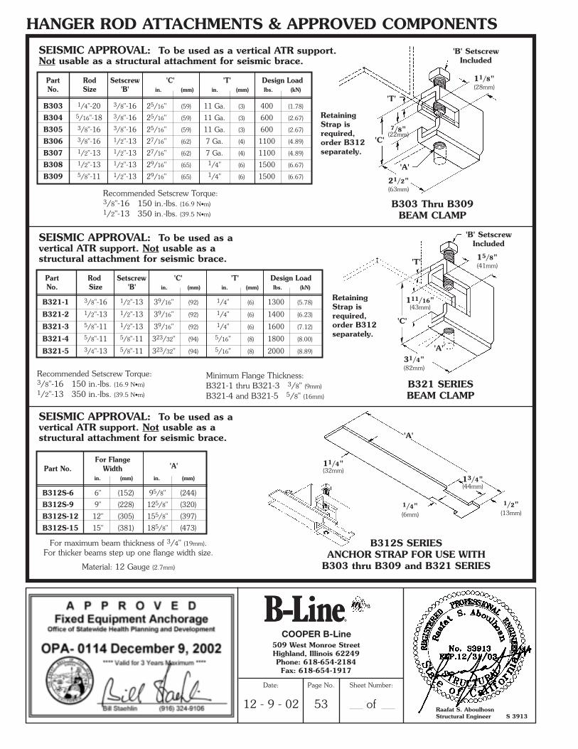
Recommended Setscrew Torque:3/8"-16 150 in.-lbs. (16.9 N•m)1/2"-13 350 in.-lbs. (39.5 N•m)
Recommended Setscrew Torque:3/8"-16 150 in.-lbs. (16.9 N•m)1/2"-13 350 in.-lbs. (39.5 N•m)
For maximum beam thickness of 3/4" (19mm).For thicker beams step up one flange width size.
Material: 12 Gauge (2.7mm)
7/8"(22mm)
'B' SetscrewIncluded
21/2"(63mm)
11/8"(28mm)
'C'
'T'
'A'
B303 Thru B309 BEAM CLAMP
111/16"(43mm)
15/8"(41mm)
31/4"(82mm)
B312S SERIESANCHOR STRAP FOR USE WITH
B303 thru B309 and B321 SERIES
For FlangePart No. Width 'A'
in. (mm) in. (mm)
B312S-6 6" (152) 95/8" (244)
B312S-9 9" (228) 125/8" (320)
B312S-12 12" (305) 155/8" (397)
B312S-15 15" (381) 185/8" (473)
Part Rod Setscrew 'C' 'T' Design LoadNo. Size 'B' in. (mm) in. (mm) lbs. (kN)
B303 1/4"-20 3/8"-16 25/16" (59) 11 Ga. (3) 400 (1.78)
B304 5/16"-18 3/8"-16 25/16" (59) 11 Ga. (3) 600 (2.67)
B305 3/8"-16 3/8"-16 25/16" (59) 11 Ga. (3) 600 (2.67)
B306 3/8"-16 1/2"-13 27/16" (62) 7 Ga. (4) 1100 (4.89)
B307 1/2"-13 1/2"-13 27/16" (62) 7 Ga. (4) 1100 (4.89)
B308 1/2"-13 1/2"-13 29/16" (65) 1/4" (6) 1500 (6.67)
B309 5/8"-11 1/2"-13 29/16" (65) 1/4" (6) 1500 (6.67)
Part Rod Setscrew 'C' 'T' Design LoadNo. Size 'B' in. (mm) in. (mm) lbs. (kN)
B321-1 3/8"-16 1/2"-13 39/16" (92) 1/4" (6) 1300 (5.78)
B321-2 1/2"-13 1/2"-13 39/16" (92) 1/4" (6) 1400 (6.23)
B321-3 5/8"-11 1/2"-13 39/16" (92) 1/4" (6) 1600 (7.12)
B321-4 5/8"-11 5/8"-11 323/32" (94) 5/16" (8) 1800 (8.00)
B321-5 3/4"-13 5/8"-11 323/32" (94) 5/16" (8) 2000 (8.89)
'A'
RetainingStrap isrequired,order B312separately.
RetainingStrap isrequired,order B312separately.
Minimum Flange Thickness:B321-1 thru B321-3 3/8" (9mm)
B321-4 and B321-5 5/8" (16mm)
'A'
'T'
'B' SetscrewIncluded
1/2"(13mm)
13/4"(44mm)
1/4"(6mm)
11/4"(32mm)
SEISMIC APPROVAL: To be used as avertical ATR support. Not usable as astructural attachment for seismic brace.
SEISMIC APPROVAL: To be used as avertical ATR support. Not usable as astructural attachment for seismic brace.
SEISMIC APPROVAL: To be used as a vertical ATR support.Not usable as a structural attachment for seismic brace.
B321 SERIESBEAM CLAMP
COOPER B-Line
Raafat S. AboulhosnStructural Engineer S 3913
509 West Monroe StreetHighland, Illinois 62249Phone: 618-654-2184Fax: 618-654-1917
Date:
12 - 9 - 02
Page No.
53
Sheet Number:
of
'C'
**SRS2002-OSpg.40-53 (11/02) N 1/3/03 5:13 PM Page 14
HANGER ROD ATTACHMENTS & APPROVED COMPONENTS
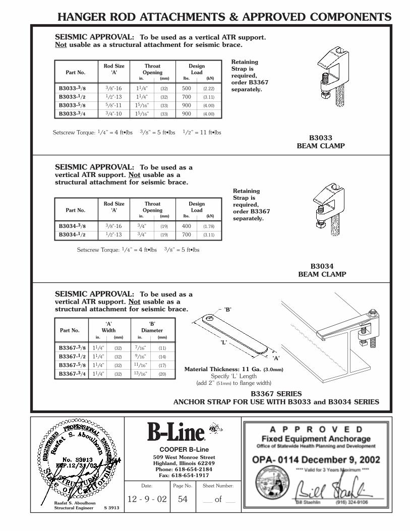
B3033 BEAM CLAMP
B3367 SERIESANCHOR STRAP FOR USE WITH B3033 and B3034 SERIES
B3034BEAM CLAMP
Setscrew Torque: 1/4” = 4 ft•lbs 3/8” = 5 ft•lbs 1/2” = 11 ft•lbs
Setscrew Torque: 1/4” = 4 ft•lbs 3/8” = 5 ft•lbs
Material Thickness: 11 Ga. (3.0mm)Specify ‘L’ Length
(add 2” (51mm) to flange width)
Rod Size Throat DesignPart No. 'A' Opening Load
in. (mm) lbs. (kN)
B3033-3/8 3/8"-16 11/4" (32) 500 (2.22)
B3033-1/2 1/2"-13 11/4" (32) 700 (3.11)
B3033-5/8 5/8"-11 15/16" (33) 900 (4.00)
B3033-3/4 3/4"-10 15/16" (33) 900 (4.00)
Rod Size Throat DesignPart No. 'A' Opening Load
in. (mm) lbs. (kN)
B3034-3/8 3/8"-16 3/4" (19) 400 (1.78)
B3034-1/2 1/2"-13 3/4" (19) 700 (3.11)
‘A’ ‘B’Part No. Width Diameter
in. (mm) in. (mm)
B3367-3/8 11/4" (32) 7/16" (11)
B3367-1/2 11/4" (32) 9/16" (14)
B3367-5/8 11/4" (32) 11/16" (17)
B3367-3/4 11/4" (32) 13/16" (20)
’B’
’L’
’A’
SEISMIC APPROVAL: To be used as avertical ATR support. Not usable as astructural attachment for seismic brace.
SEISMIC APPROVAL: To be used as avertical ATR support. Not usable as astructural attachment for seismic brace.
SEISMIC APPROVAL: To be used as a vertical ATR support.Not usable as a structural attachment for seismic brace.
RetainingStrap isrequired,order B3367separately.
RetainingStrap isrequired,order B3367separately.
COOPER B-Line
Raafat S. AboulhosnStructural Engineer S 3913
509 West Monroe StreetHighland, Illinois 62249Phone: 618-654-2184Fax: 618-654-1917
Date:
12 - 9 - 02
Page No.
54
Sheet Number:
of
**SRS2002-OSpg.54-69 (11/02) N 1/3/03 5:29 PM Page 1
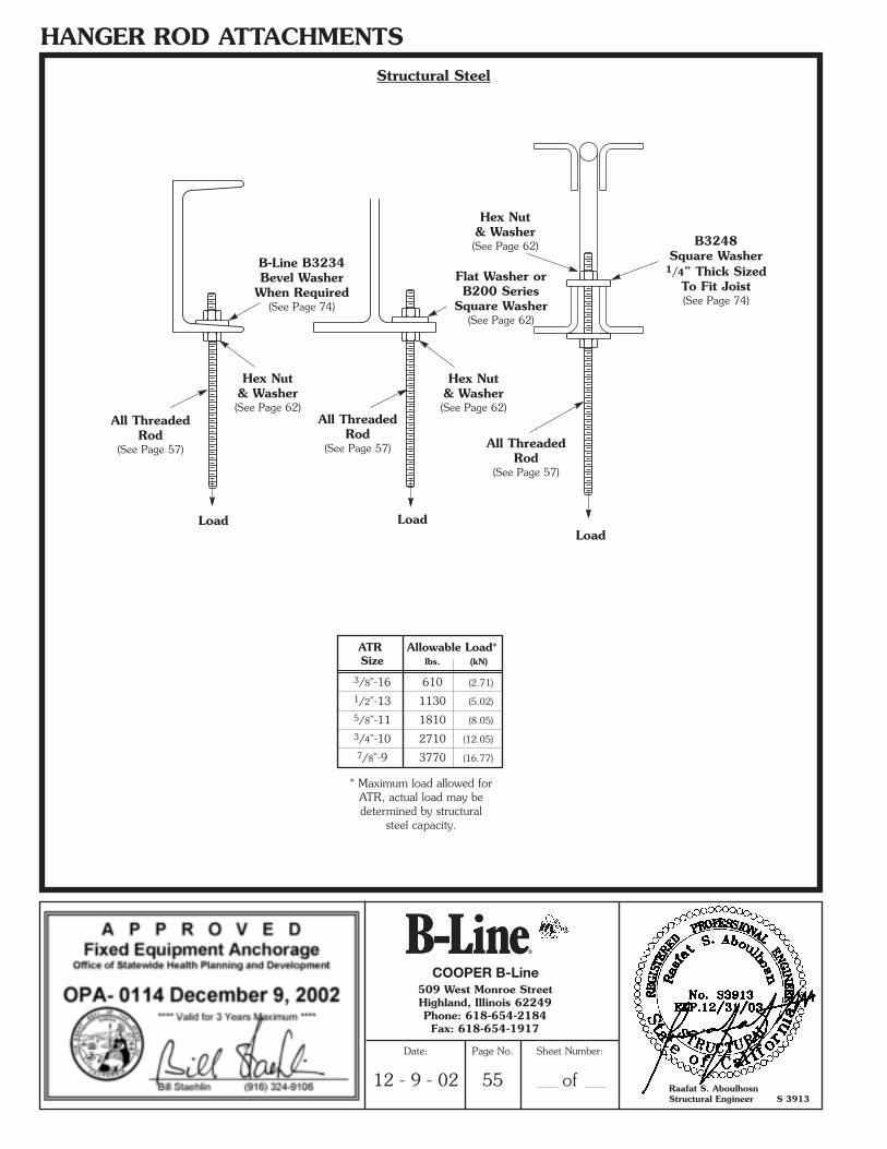
HANGER ROD ATTACHMENTSStructural Steel
Hex Nut& Washer(See Page 62)
Hex Nut& Washer(See Page 62)
All ThreadedRod
(See Page 57)
Load Load
B-Line B3234Bevel Washer
When Required(See Page 74)
Load
All ThreadedRod
(See Page 57) All ThreadedRod
(See Page 57)
B3248Square Washer
1/4” Thick SizedTo Fit Joist(See Page 74)
Hex Nut& Washer(See Page 62)
* Maximum load allowed forATR, actual load may bedetermined by structural
steel capacity.
ATR Allowable Load*Size lbs. (kN)
3/8"-16 610 (2.71)
1/2"-13 1130 (5.02)
5/8"-11 1810 (8.05)
3/4"-10 2710 (12.05)
7/8"-9 3770 (16.77)
Flat Washer orB200 Series
Square Washer(See Page 62)
COOPER B-Line
Raafat S. AboulhosnStructural Engineer S 3913
509 West Monroe StreetHighland, Illinois 62249Phone: 618-654-2184Fax: 618-654-1917
Date:
12 - 9 - 02
Page No.
55
Sheet Number:
of
**SRS2002-OSpg.54-69 (11/02) N 1/3/03 5:29 PM Page 2
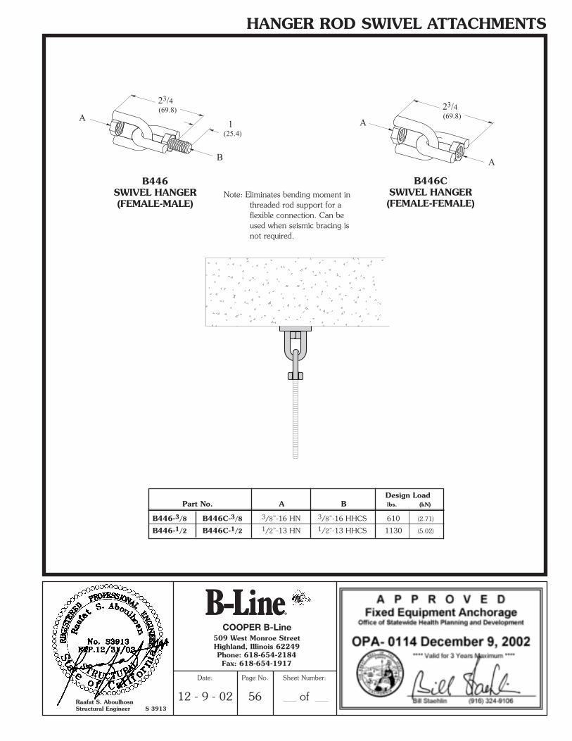
HANGER ROD SWIVEL ATTACHMENTS
Note: Eliminates bending moment inthreaded rod support for aflexible connection. Can beused when seismic bracing isnot required.
Design LoadPart No. A B lbs. (kN)
B446-3/8 B446C-3/8 3/8”-16 HN 3/8”-16 HHCS 610 (2.71)
B446-1/2 B446C-1/2 1/2”-13 HN 1/2”-13 HHCS 1130 (5.02)
A
B
23/4(69.8)
1(25.4)
23/4(69.8)
A
A
B446SWIVEL HANGER(FEMALE-MALE)
B446CSWIVEL HANGER(FEMALE-FEMALE)
COOPER B-Line
Raafat S. AboulhosnStructural Engineer S 3913
509 West Monroe StreetHighland, Illinois 62249Phone: 618-654-2184Fax: 618-654-1917
Date:
12 - 9 - 02
Page No.
56
Sheet Number:
of
**SRS2002-OSpg.54-69 (11/02) N 1/3/03 5:29 PM Page 3
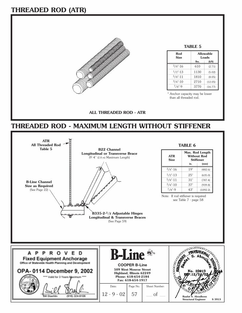
THREADED ROD (ATR)
THREADED ROD - MAXIMUM LENGTH WITHOUT STIFFENER
Rod AllowableSize Loads
lbs. (kN)
3/8"-16 610 (2.71)
1/2"-13 1130 (5.02)
5/8"-11 1810 (8.05)
3/4"-10 2710 (12.05)
7/8"-9 3770 (16.77)
ALL THREADED ROD - ATR
TABLE 5
Max. Rod LengthATR Without RodSize Stiffener
in. (mm)
3/8"-16 19" (482.6)
1/2"-13 25" (635.0)
5/8"-11 31" (787.4)
3/4"-10 37" (939.8)
7/8"-9 43" (1092.2)
TABLE 6
Note: If rod stiffener is requiredsee Table 7 - page 58
ATRAll Threaded Rod
Table 5
B335-2-1/2 Adjustable HingesLongitudinal & Transverse Braces
(See Page 59)
B-Line ChannelSize as Required
(See Page 22)
B22 ChannelLongitudinal or Transverse Brace
(9’-4” (2.8 m) Maximum Length)
* Anchor capacity may be lower than all threaded rod.
COOPER B-Line
Raafat S. AboulhosnStructural Engineer S 3913
509 West Monroe StreetHighland, Illinois 62249Phone: 618-654-2184Fax: 618-654-1917
Date:
12 - 9 - 02
Page No.
57
Sheet Number:
of
**SRS2002-OSpg.54-69 (11/02) N 1/3/03 5:29 PM Page 4
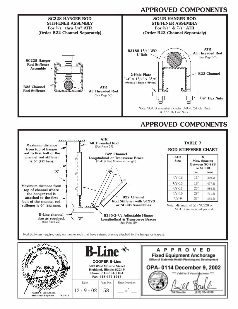
APPROVED COMPONENTS
APPROVED COMPONENTS
SC228 HANGER RODSTIFFENER ASSEMBLYFor 3/8" thru 5/8" ATR
(Order B22 Channel Separately)
SC-UB HANGER RODSTIFFENER ASSEMBLY
For 3/4" & 7/8" ATR(Order B22 Channel Separately)
Note: SC-UB assembly includes U-Bolt, 2-Hole Plate& 3/8"-16 Hex Nuts.
ATRAll Threaded Rod
(See Page 57)
B3188-11/4” WOU-Bolt
2-Hole Plate1/4” x 15/8” x 31/2”(6mm x 41mm x 89mm)
ATRAll Threaded Rod
(See Page 57)
B22 Channel
3/8” Hex Nuts
B22 ChannelRod Stiffener
SC228 HangerRod Stiffener
Assembly
ATR XSize Max. Spacing
Between SC-228or SC-UB
in. (mm)
3/8"-16 13" (330.2)
1/2"-13 18" (457.2)
5/8"-11 23" (584.2)
3/4"-10 28" (711.2)
7/8"-9 33" (838.2)
TABLE 7
ROD STIFFENER CHART
Note: Minimum of (2) - SC228 orSC-UB are required per rod.
Rod Stiffeners required only on hanger rods that have seismic bracing attached to the hanger or trapeze.
B335-2-1/2 Adjustable HingesLongitudinal & Transverse Braces
(See Page 59)
B-Line channelsize as required.
(See Page 22)
Maximum distancefrom top of hanger
rod to first bolt of thechannel rod stiffener
is 6” (152.4mm).
Maximum distance fromtop of channel where
the hanger rod isattached to the first
bolt of the channel rodstiffener is 6” (152.4mm).
B22 ChannelRod Stiffener with SC228
or SC-UB Assemblies
ATRAll Threaded Rod
(See Page 57)
‘X’
B22 ChannelLongitudinal or Transverse Brace
(9’-4” (2.8 m) Maximum Length)
COOPER B-Line
Raafat S. AboulhosnStructural Engineer S 3913
509 West Monroe StreetHighland, Illinois 62249Phone: 618-654-2184Fax: 618-654-1917
Date:
12 - 9 - 02
Page No.
58
Sheet Number:
of
**SRS2002-OSpg.54-69 (11/02) N 1/3/03 5:29 PM Page 5
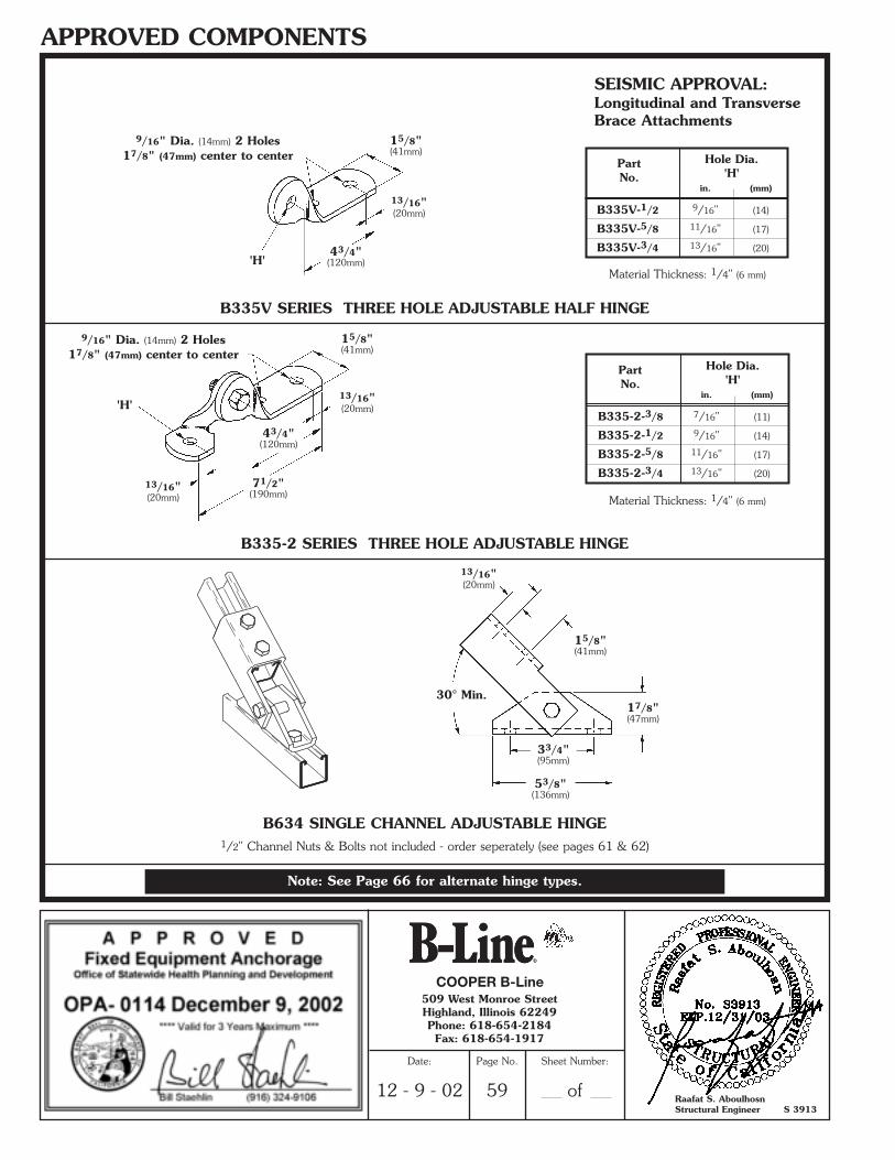
APPROVED COMPONENTS
B335V SERIES THREE HOLE ADJUSTABLE HALF HINGE
B335-2 SERIES THREE HOLE ADJUSTABLE HINGE
Material Thickness: 1/4" (6 mm)
SEISMIC APPROVAL:Longitudinal and TransverseBrace Attachments
Material Thickness: 1/4" (6 mm)
Part Hole Dia.
No. 'H'in. (mm)
B335-2-3/8 7/16" (11)
B335-2-1/2 9/16" (14)
B335-2-5/8 11/16" (17)
B335-2-3/4 13/16" (20)
13/16"(20mm)
13/16"(20mm)
13/16"(20mm)
43/4"(120mm)
43/4"(120mm)
71/2"(190mm)
'H'
'H'
9/16" Dia. (14mm) 2 Holes17/8" (47mm) center to center
9/16" Dia. (14mm) 2 Holes17/8" (47mm) center to center
15/8"(41mm)
15/8"(41mm)
Part Hole Dia.
No. 'H'in. (mm)
B335V-1/2 9/16" (14)
B335V-5/8 11/16" (17)
B335V-3/4 13/16" (20)
30° Min.
B634 SINGLE CHANNEL ADJUSTABLE HINGE1/2" Channel Nuts & Bolts not included - order seperately (see pages 61 & 62)
15/8"(41mm)
17/8"(47mm)
33/4"(95mm)
53/8"(136mm)
13/16"(20mm)
Note: See Page 66 for alternate hinge types.
COOPER B-Line
Raafat S. AboulhosnStructural Engineer S 3913
509 West Monroe StreetHighland, Illinois 62249Phone: 618-654-2184Fax: 618-654-1917
Date:
12 - 9 - 02
Page No.
59
Sheet Number:
of
**SRS2002-OSpg.54-69 (11/02) N 1/3/03 5:29 PM Page 6
APPROVED COMPONENTS
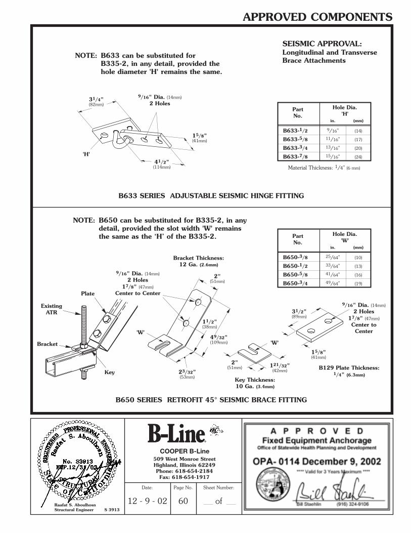
B633 SERIES ADJUSTABLE SEISMIC HINGE FITTING
Material Thickness: 1/4" (6 mm)
Part Hole Dia.
No. 'H'in. (mm)
B633-1/2 9/16" (14)
B633-5/8 11/16" (17)
B633-3/4 13/16" (20)
B633-7/8 15/16" (24)
15/8"(41mm)
31/4"(82mm)
'H'41/2"(114mm)
9/16" Dia. (14mm)2 Holes
SEISMIC APPROVAL:Longitudinal and TransverseBrace Attachments
NOTE: B633 can be substituted for B335-2, in any detail, provided the hole diameter 'H' remains the same.
B650 SERIES RETROFIT 45° SEISMIC BRACE FITTING
2"(51mm)
2"(51mm)
15/8"(41mm)
'W'
'W'
23/32"(53mm)
11/2"(38mm)
121/32"(42mm)
49/32"(109mm)
31/2"(89mm)
9/16" Dia. (14mm)2 Holes
17/8" (47mm)Center to Center
9/16" Dia. (14mm)2 Holes
17/8" (47mm)Center to
Center
NOTE: B650 can be substituted for B335-2, in any detail, provided the slot width 'W' remains the same as the ‘H’ of the B335-2.
Key Thickness:10 Ga. (3.4mm)
B129 Plate Thickness:1/4" (6.3mm)
Bracket Thickness:12 Ga. (2.6mm)
Part Hole Dia.
No. 'W'in. (mm)
B650-3/8 25/64" (10)
B650-1/2 33/64" (13)
B650-5/8 41/64" (16)
B650-3/4 49/64" (19)
Key
Plate
ExistingATR
Bracket
COOPER B-Line
Raafat S. AboulhosnStructural Engineer S 3913
509 West Monroe StreetHighland, Illinois 62249Phone: 618-654-2184Fax: 618-654-1917
Date:
12 - 9 - 02
Page No.
60
Sheet Number:
of
**SRS2002-OSpg.54-69 (11/02) N 1/3/03 5:29 PM Page 7
APPROVED COMPONENTS
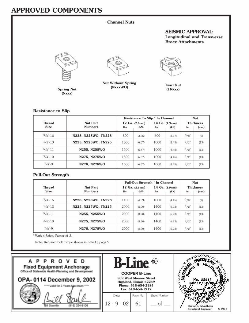
Spring Nut(Nxxx)
Nut Without Spring(NxxxWO) Twirl Nut
(TNxxx)
Channel Nuts
Resistance to Slip
Resistance To Slip * In Channel NutThread Nut Part 12 Ga. (2.6mm) 14 Ga. (1.9mm) Thickness
Size Numbers lbs. (kN) lbs. (kN) in. (mm)
3/8"-16 N228, N228WO, TN228 800 (3.56) 600 (2.67) 3/8" (9)
1/2"-13 N225, N225WO, TN225 1500 (6.67) 1000 (4.45) 1/2" (13)
5/8"-11 N255, N255WO 1500 (6.67) 1000 (4.45) 1/2" (13)
3/4"-10 N275, N275WO 1500 (6.67) 1000 (4.45) 1/2" (13)
7/8"-9 N278, N278WO 1500 (6.67) 1000 (4.45) 1/2" (13)
Pull-Out Strength
* With a Safety Factor of 3.
Note: Required bolt torque shown in note D) page 9.
SEISMIC APPROVAL:Longitudinal and TransverseBrace Attachments
Pull-Out Strength * In Channel NutThread Nut Part 12 Ga. (2.6mm) 14 Ga. (1.9mm) Thickness
Size Numbers lbs. (kN) lbs. (kN) in. (mm)
3/8"-16 N228, N228WO, TN228 1100 (4.89) 1000 (4.45) 3/8" (9)
1/2"-13 N225, N225WO, TN225 2000 (8.90) 1400 (6.23) 1/2" (13)
5/8"-11 N255, N255WO 2000 (8.90) 1400 (6.23) 1/2" (13)
3/4"-10 N275, N275WO 2000 (8.90) 1400 (6.23) 1/2" (13)
7/8"-9 N278, N278WO 2000 (8.90) 1400 (6.23) 1/2" (13)
COOPER B-Line
Raafat S. AboulhosnStructural Engineer S 3913
509 West Monroe StreetHighland, Illinois 62249Phone: 618-654-2184Fax: 618-654-1917
Date:
12 - 9 - 02
Page No.
61
Sheet Number:
of
**SRS2002-OSpg.54-69 (11/02) N 1/3/03 5:29 PM Page 8
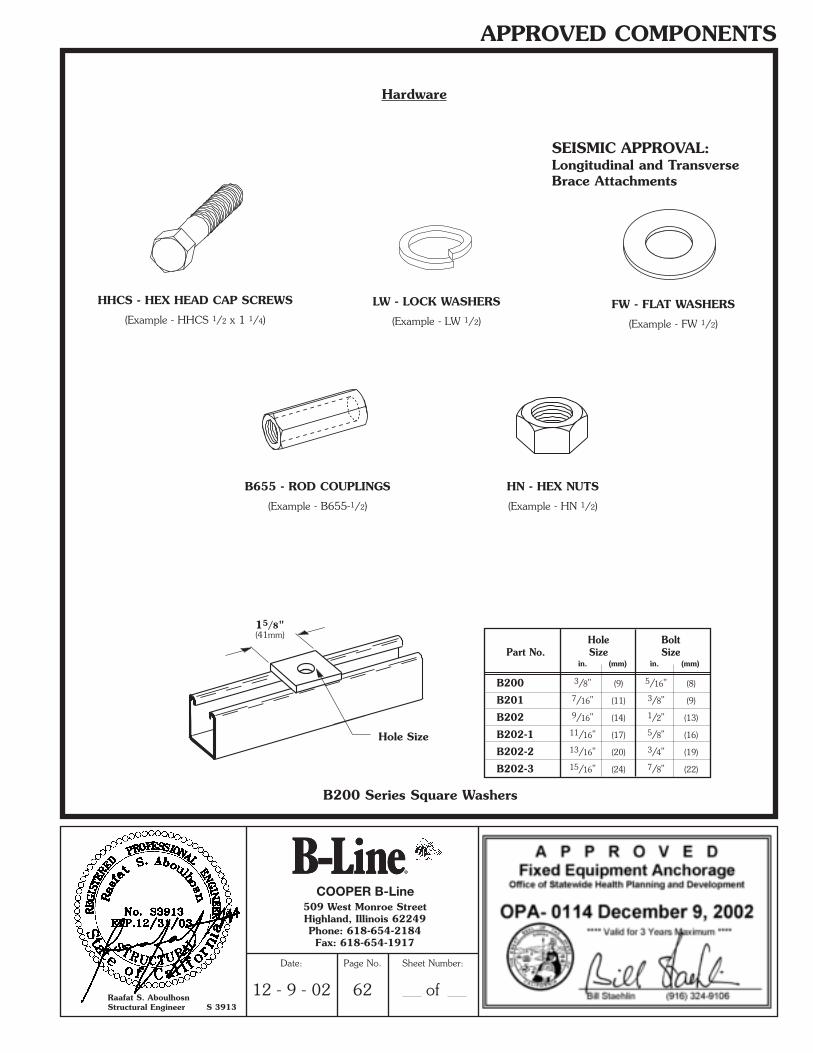
APPROVED COMPONENTS
Hardware
LW - LOCK WASHERS
(Example - LW 1/2)
HHCS - HEX HEAD CAP SCREWS
(Example - HHCS 1/2 x 1 1/4)FW - FLAT WASHERS
(Example - FW 1/2)
HN - HEX NUTS
(Example - HN 1/2)
B200 Series Square Washers
B655 - ROD COUPLINGS
(Example - B655-1/2)
SEISMIC APPROVAL:Longitudinal and TransverseBrace Attachments
Hole BoltPart No. Size Size
in. (mm) in. (mm)
B200 3/8" (9) 5/16" (8)
B201 7/16" (11) 3/8" (9)
B202 9/16" (14) 1/2" (13)
B202-1 11/16" (17) 5/8" (16)
B202-2 13/16" (20) 3/4" (19)
B202-3 15/16" (24) 7/8" (22)
15/8"(41mm)
Hole Size
COOPER B-Line
Raafat S. AboulhosnStructural Engineer S 3913
509 West Monroe StreetHighland, Illinois 62249Phone: 618-654-2184Fax: 618-654-1917
Date:
12 - 9 - 02
Page No.
62
Sheet Number:
of
**SRS2002-OSpg.54-69 (11/02) N 1/3/03 5:29 PM Page 9