hand gesture controlled robot - …...hand gesture controlled robot overview • introduction •...
TRANSCRIPT
HAND GESTURE CONTROLLED ROBOT
Overview
• Introduction• Block Diagram• Hardware Requirements• Software used• Applications• References
Introduction
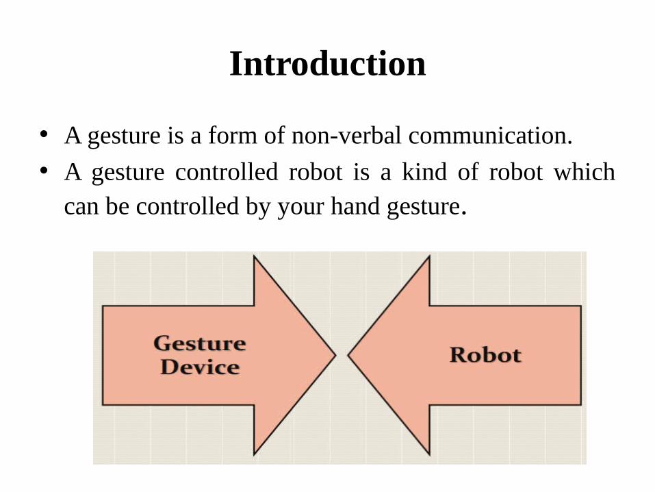
• A gesture is a form of non-verbal communication.• A gesture controlled robot is a kind of robot which
can be controlled by your hand gesture.
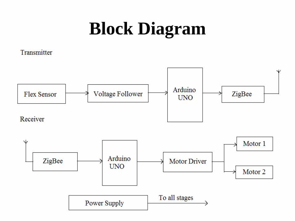
Block Diagram
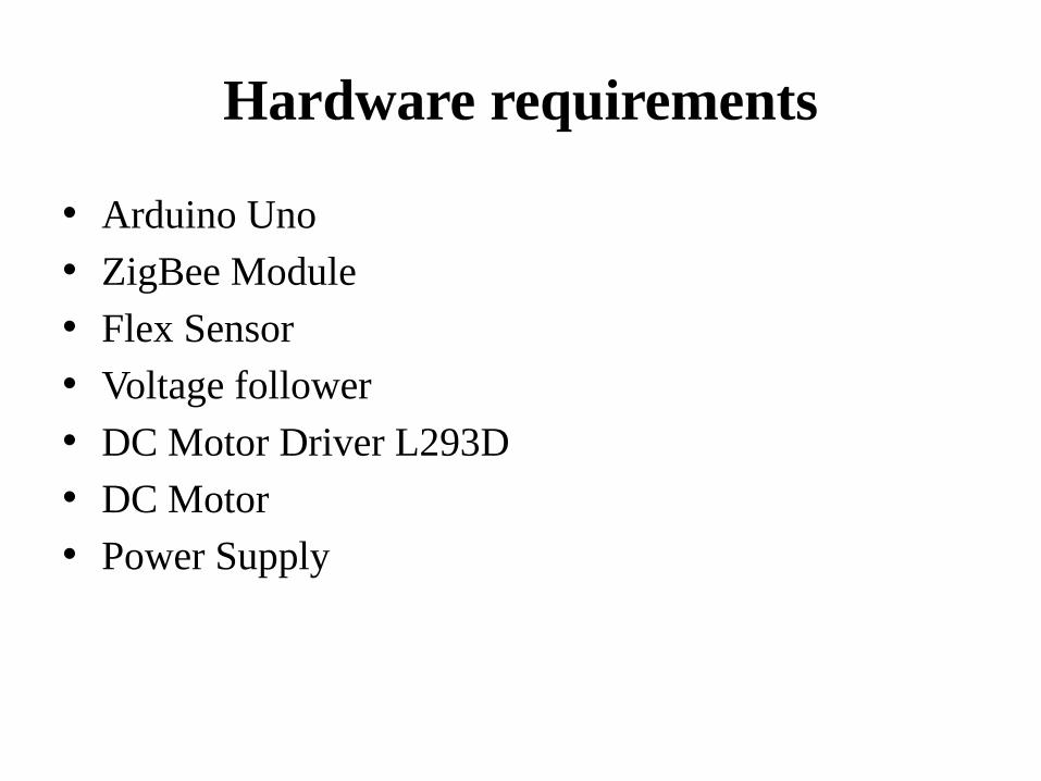
Hardware requirements
• Arduino Uno • ZigBee Module• Flex Sensor• Voltage follower• DC Motor Driver L293D• DC Motor• Power Supply
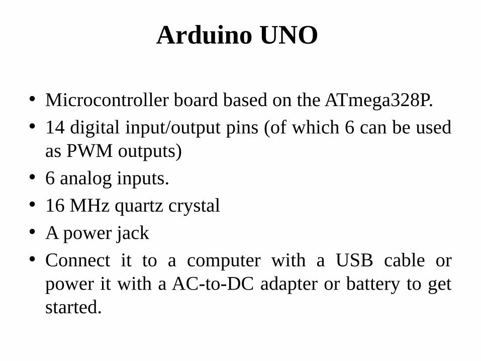
Arduino UNO
• Microcontroller board based on the ATmega328P.• 14 digital input/output pins (of which 6 can be used
as PWM outputs)• 6 analog inputs.• 16 MHz quartz crystal• A power jack• Connect it to a computer with a USB cable or
power it with a AC-to-DC adapter or battery to get started.
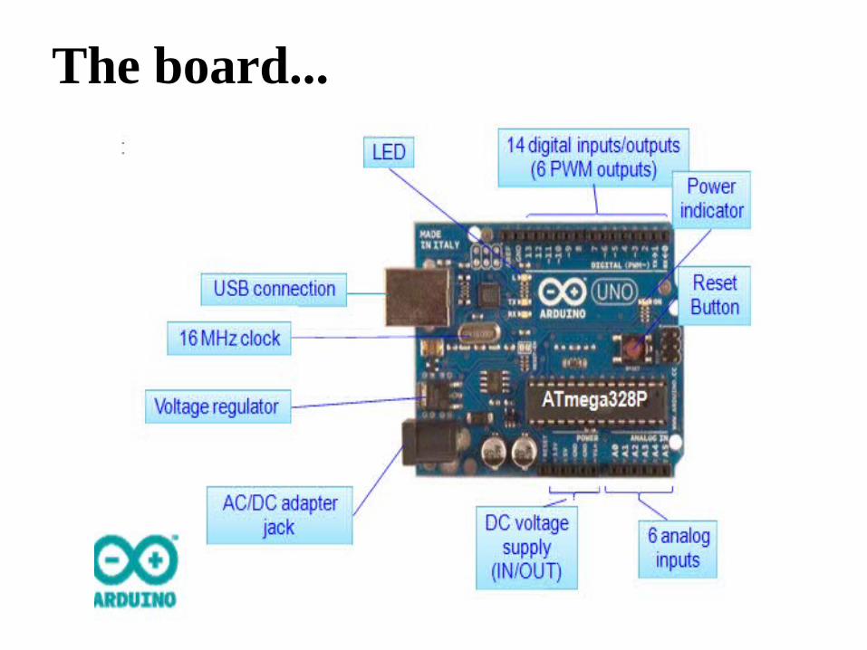
The board...
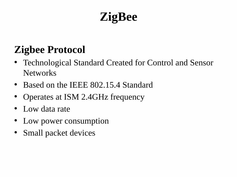
ZigBee
Zigbee Protocol• Technological Standard Created for Control and Sensor
Networks • Based on the IEEE 802.15.4 Standard • Operates at ISM 2.4GHz frequency• Low data rate• Low power consumption• Small packet devices
Motivation for ZigBee
• Low cost
• Secure
• Reliable
• Flexible and extendable
• Low power consumption
• Easy and inexpensive to deploy
• Global with use of unlicensed radio bands
• Integrated intelligence for network set-up and message routing.
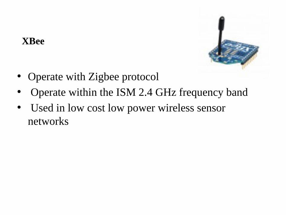
XBee
• Operate with Zigbee protocol• Operate within the ISM 2.4 GHz frequency band• Used in low cost low power wireless sensor
networks
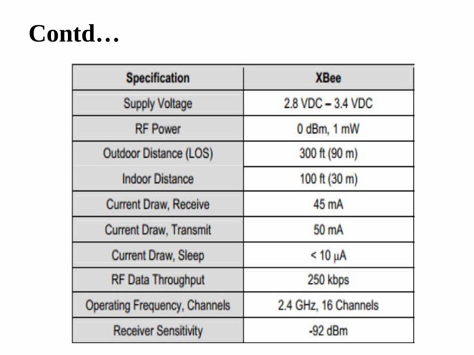
Contd…
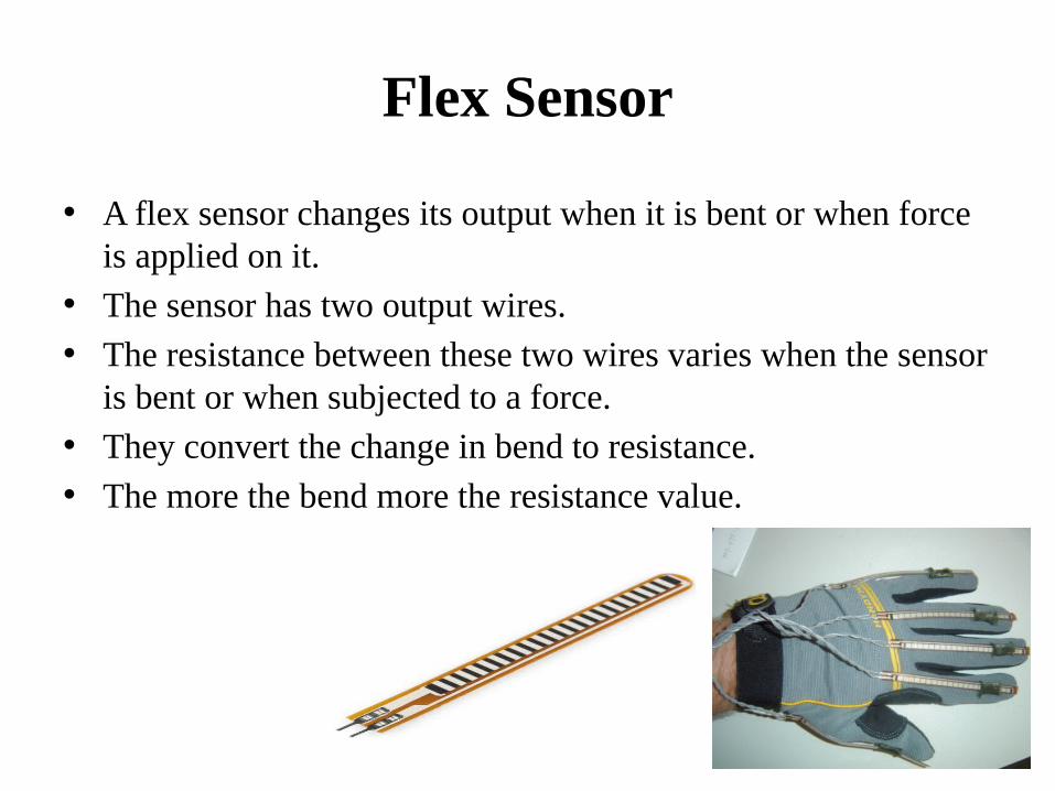
Flex Sensor
• A flex sensor changes its output when it is bent or when force is applied on it.
• The sensor has two output wires. • The resistance between these two wires varies when the sensor
is bent or when subjected to a force. • They convert the change in bend to resistance. • The more the bend more the resistance value.
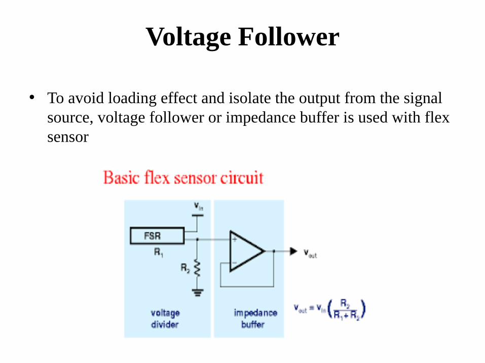
Voltage Follower
• To avoid loading effect and isolate the output from the signal source, voltage follower or impedance buffer is used with flex sensor
DC Motor Driver(L293D)
• L293D has quadruple high current half-H drivers.• Wide Supply-Voltage Range: 4.5 V to 36 V• High-Noise-Immunity Inputs• Output Current 600mA Per Channel • Peak Output Current 1.2A Per Channel.

Pin Diagram
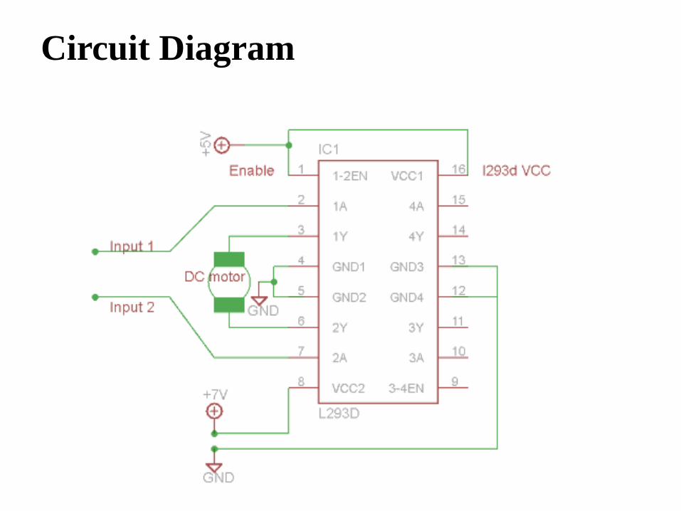
Circuit Diagram
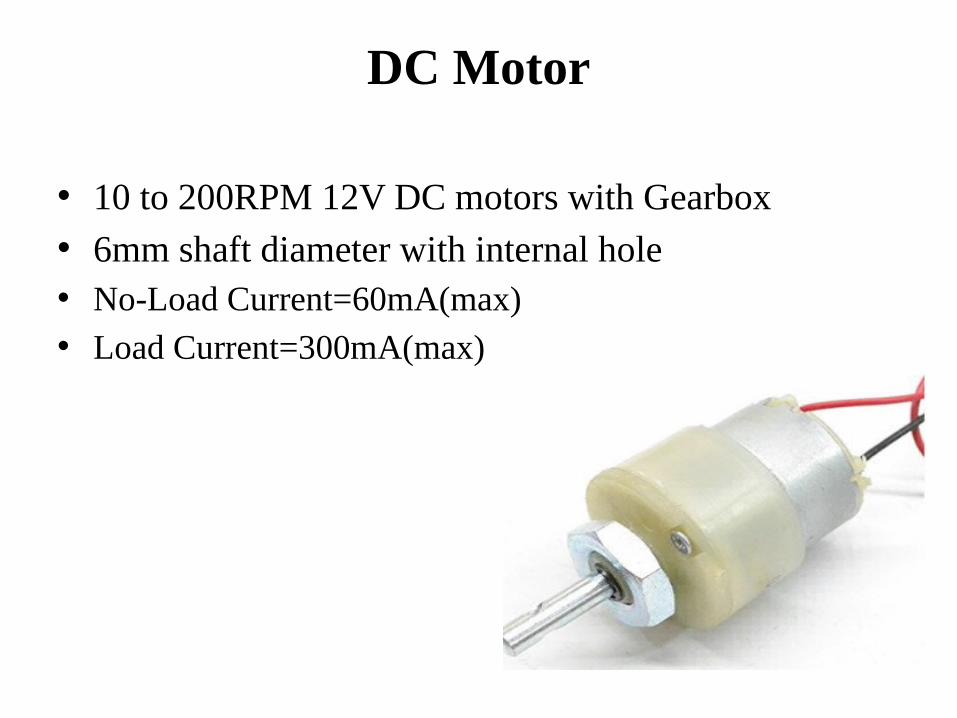
DC Motor
• 10 to 200RPM 12V DC motors with Gearbox• 6mm shaft diameter with internal hole• No-Load Current=60mA(max) • Load Current=300mA(max)
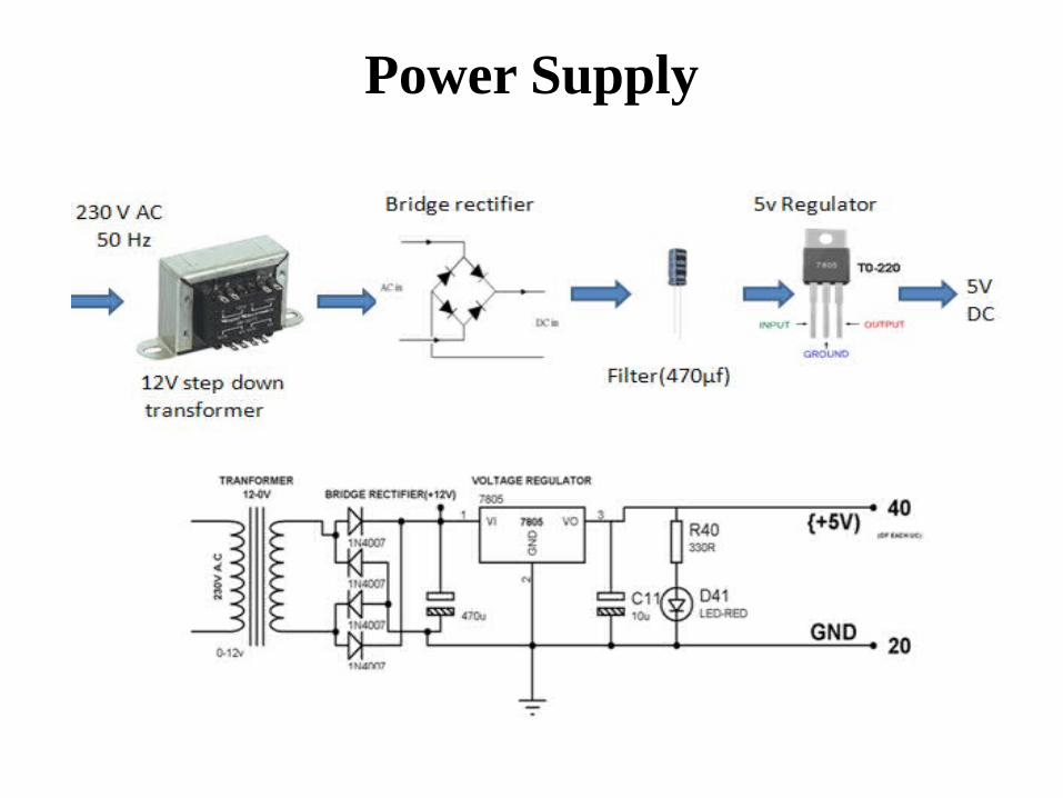
Power Supply
Software Used..
• Arduino IDE
Programming Languages Used..
• Embedded C/C++
Application
• Hospitals• Industrial robots• Automobiles
References
• www.arduino.org
• www.beyondlogic.org
• www.wikipedia.org
• www.elementzonline.com
• www.elementztechblog.wordpress.com

Questions????

THANK YOU