haas automation - lathe auto parts loader …...covering haas automation, inc. cnc equipment...
TRANSCRIPT
,
Haas Automation Inc.2800 Sturgis Road
Oxnard, CA 93030-8933U.S.A. | HaasCNC.com
© 2020 Haas Automation, Inc. All Rights Reserved. Copy by Permission Only. Copyright Strictly Enforced.
Lathe Auto Parts LoaderOperator’s Manual Supplement
Next Generation Control96-8040
Revision BJanuary 2020
EnglishOriginal Instructions

i
© 2020 Haas Automation, Inc.
All rights reserved. No part of this publication may be reproduced, stored in a retrieval system, ortransmitted, in any form, or by any means, mechanical, electronic, photocopying, recording, orotherwise, without the written permission of Haas Automation, Inc. No patent liability is assumed withrespect to the use of the information contained herein. Moreover, because Haas Automation strivesconstantly to improve its high-quality products, the information contained in this manual is subject tochange without notice. We have taken every precaution in the preparation of this manual; nevertheless,Haas Automation assumes no responsibility for errors or omissions, and we assume no liability fordamages resulting from the use of the information contained in this publication.

ii
This product uses Java Technology from Oracle Corporation and we request that you acknowledge that Oracle owns the Java Trademark and all Java related Trademarks and agree to comply with the trademark guidelines at www.oracle.com/us/legal/third-party-trademarks/index.html.
Any further distribution of the Java programs (beyond this appliance/machine) is subject to a legally binding End User License Agreement with Oracle. Any use of the commercial features for production purposes requires a separate license from Oracle.
iii
LIMITED WARRANTY CERTIFICATEHaas Automation, Inc.
Covering Haas Automation, Inc. CNC Equipment
Effective September 1, 2010
Haas Automation Inc. (“Haas” or “Manufacturer”) provides a limited warranty on all newmills, turning centers, and rotary machines (collectively, “CNC Machines”) and theircomponents (except those listed below under Limits and Exclusions of Warranty)(“Components”) that are manufactured by Haas and sold by Haas or its authorizeddistributors as set forth in this Certificate. The warranty set forth in this Certificate is alimited warranty, it is the only warranty by Manufacturer, and is subject to the terms andconditions of this Certificate.
Limited Warranty Coverage
Each CNC Machine and its Components (collectively, “Haas Products”) are warranted byManufacturer against defects in material and workmanship. This warranty is provided onlyto an end-user of the CNC Machine (a “Customer”). The period of this limited warranty isone (1) year. The warranty period commences on the date the CNC Machine is installed atthe Customer’s facility. Customer may purchase an extension of the warranty period froman authorized Haas distributor (a “Warranty Extension”), any time during the first year ofownership.
Repair or Replacement Only
Manufacturer’s sole liability, and Customer’s exclusive remedy under this warranty, withrespect to any and all Haas products, shall be limited to repairing or replacing, at thediscretion of the Manufacturer, the defective Haas product.
Disclaimer of Warranty
This warranty is Manufacturer’s sole and exclusive warranty, and is in lieu of all otherwarranties of whatever kind or nature, express or implied, written or oral, including, but notlimited to, any implied warranty of merchantability, implied warranty of fitness for aparticular purpose, or other warranty of quality or performance or noninfringement. All suchother warranties of whatever kind are hereby disclaimed by Manufacturer and waived byCustomer.
iv
Limits and Exclusions of Warranty
Components subject to wear during normal use and over time, including, but not limited to,paint, window finish and condition, light bulbs, seals, wipers, gaskets, chip removal system(e.g., augers, chip chutes), belts, filters, door rollers, tool changer fingers, etc., are excludedfrom this warranty. Manufacturer’s specified maintenance procedures must be adhered toand recorded in order to maintain this warranty. This warranty is void if Manufacturerdetermines that (i) any Haas Product was subjected to mishandling, misuse, abuse,neglect, accident, improper installation, improper maintenance, improper storage, orimproper operation or application, including the use of improper coolants or other fluids, (ii)any Haas Product was improperly repaired or serviced by Customer, an unauthorizedservice technician, or other unauthorized person, (iii) Customer or any person makes orattempts to make any modification to any Haas Product without the prior writtenauthorization of Manufacturer, and/or (iv) any Haas Product was used for anynon-commercial use (such as personal or household use). This warranty does not coverdamage or defect due to an external influence or matters beyond the reasonable control ofManufacturer, including, but not limited to, theft, vandalism, fire, weather condition (such asrain, flood, wind, lightning, or earthquake), or acts of war or terrorism.
Without limiting the generality of any of the exclusions or limitations described in thisCertificate, this warranty does not include any warranty that any Haas Product will meet anyperson’s production specifications or other requirements, or that operation of any HaasProduct will be uninterrupted or error-free. Manufacturer assumes no responsibility withrespect to the use of any Haas Product by any person, and Manufacturer shall not incurany liability to any person for any failure in design, production, operation, performance, orotherwise of any Haas Product, other than repair or replacement of same as set forth in thewarranty above.
Limitation of Liability and Damages
Manufacturer will not be liable to Customer or any other person for any compensatory,incidental, consequential, punitive, special, or other damage or claim, whether in an actionin contract, tort, or other legal or equitable theory, arising out of or related to any Haasproduct, other products or services provided by Manufacturer or an authorized distributor,service technician, or other authorized representative of Manufacturer (collectively,“authorized representative”), or the failure of parts or products made by using any HaasProduct, even if Manufacturer or any authorized representative has been advised of thepossibility of such damages, which damage or claim includes, but is not limited to, loss ofprofits, lost data, lost products, loss of revenue, loss of use, cost of down time, businessgood will, any damage to equipment, premises, or other property of any person, and anydamage that may be caused by a malfunction of any Haas product. All such damages andclaims are disclaimed by Manufacturer and waived by Customer. Manufacturer’s soleliability, and Customer’s exclusive remedy, for damages and claims for any causewhatsoever shall be limited to repair or replacement, at the discretion of Manufacturer, ofthe defective Haas Product as provided in this warranty.
v
Customer has accepted the limitations and restrictions set forth in this Certificate, including,but not limited to, the restriction on its right to recover damages, as part of its bargain withManufacturer or its Authorized Representative. Customer realizes and acknowledges thatthe price of the Haas Products would be higher if Manufacturer were required to beresponsible for damages and claims beyond the scope of this warranty.
Entire Agreement
This Certificate supersedes any and all other agreements, promises, representations, orwarranties, either oral or in writing, between the parties or by Manufacturer with respect tosubject matter of this Certificate, and contains all of the covenants and agreementsbetween the parties or by Manufacturer with respect to such subject matter. Manufacturerhereby expressly rejects any other agreements, promises, representations, or warranties,either oral or in writing, that are in addition to or inconsistent with any term or condition ofthis Certificate. No term or condition set forth in this Certificate may be modified oramended, unless by a written agreement signed by both Manufacturer and Customer.Notwithstanding the foregoing, Manufacturer will honor a Warranty Extension only to theextent that it extends the applicable warranty period.
Transferability
This warranty is transferable from the original Customer to another party if the CNCMachine is sold via private sale before the end of the warranty period, provided that writtennotice thereof is provided to Manufacturer and this warranty is not void at the time oftransfer. The transferee of this warranty will be subject to all terms and conditions of thisCertificate.
Miscellaneous
This warranty shall be governed by the laws of the State of California without application ofrules on conflicts of laws. Any and all disputes arising from this warranty shall be resolvedin a court of competent jurisdiction located in Ventura County, Los Angeles County, orOrange County, California. Any term or provision of this Certificate that is invalid orunenforceable in any situation in any jurisdiction shall not affect the validity or enforceabilityof the remaining terms and provisions hereof, or the validity or enforceability of theoffending term or provision in any other situation or in any other jurisdiction.
vi
Customer FeedbackIf you have concerns or questions regarding this Operator’s Manual, please contact us onour website, www.HaasCNC.com. Use the “Contact Us” link and send your comments tothe Customer Advocate.
Join Haas owners online and be a part of the greater CNC community at these sites:
haasparts.comYour Source for Genuine Haas Parts
www.facebook.com/HaasAutomationIncHaas Automation on Facebook
www.twitter.com/Haas_AutomationFollow us on Twitter
www.linkedin.com/company/haas-automationHaas Automation on LinkedIn
www.youtube.com/user/haasautomationProduct videos and information
www.flickr.com/photos/haasautomationProduct photos and information
vii
Customer Satisfaction PolicyDear Haas Customer,
Your complete satisfaction and goodwill are of the utmost importance to both HaasAutomation, Inc. and the Haas distributor (HFO) where you purchased your equipment.Normally, your HFO will rapidly resolve any concerns you have about your salestransaction or the operation of your equipment.
However, if your concerns are not resolved to your complete satisfaction, and you havediscussed your concerns with a member of the HFO’s management, the General Manager,or the HFO’s owner directly, please do the following:
Contact Haas Automation’s Customer Service Advocate at 805-988-6980. So that we mayresolve your concerns as quickly as possible, please have the following informationavailable when you call:
• Your company name, address, and phone number• The machine model and serial number• The HFO name, and the name of your latest contact at the HFO• The nature of your concern
If you wish to write Haas Automation, please use this address:
Haas Automation, Inc. U.S.A.2800 Sturgis RoadOxnard CA 93030Att: Customer Satisfaction Manageremail: [email protected]
Once you contact the Haas Automation Customer Service Center, we will make every effortto work directly with you and your HFO to quickly resolve your concerns. At HaasAutomation, we know that a good Customer-Distributor-Manufacturer relationship will helpensure continued success for all concerned.
International:
Haas Automation, EuropeMercuriusstraat 28, B-1930Zaventem, Belgiumemail: [email protected]
Haas Automation, AsiaNo. 96 Yi Wei Road 67,Waigaoqiao FTZShanghai 200131 P.R.C.email: [email protected]

viii
ix
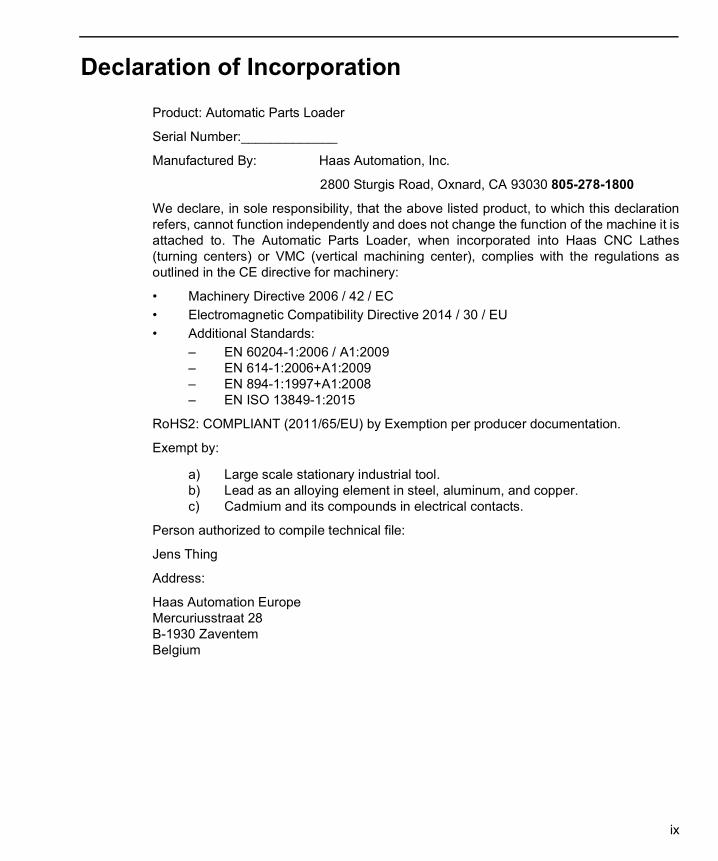
Declaration of IncorporationProduct: Automatic Parts Loader
Serial Number:_____________
Manufactured By: Haas Automation, Inc.
2800 Sturgis Road, Oxnard, CA 93030 805-278-1800
We declare, in sole responsibility, that the above listed product, to which this declarationrefers, cannot function independently and does not change the function of the machine it isattached to. The Automatic Parts Loader, when incorporated into Haas CNC Lathes(turning centers) or VMC (vertical machining center), complies with the regulations asoutlined in the CE directive for machinery:
• Machinery Directive 2006 / 42 / EC• Electromagnetic Compatibility Directive 2014 / 30 / EU• Additional Standards:
– EN 60204-1:2006 / A1:2009– EN 614-1:2006+A1:2009– EN 894-1:1997+A1:2008– EN ISO 13849-1:2015
RoHS2: COMPLIANT (2011/65/EU) by Exemption per producer documentation.
Exempt by:
a) Large scale stationary industrial tool.b) Lead as an alloying element in steel, aluminum, and copper.c) Cadmium and its compounds in electrical contacts.
Person authorized to compile technical file:
Jens Thing
Address:
Haas Automation EuropeMercuriusstraat 28B-1930 ZaventemBelgium
x
USA: Haas Automation certifies this machine to be in compliance with the OSHA and ANSIdesign and manufacturing standards listed below. Operation of this machine will becompliant with the below-listed standards only as long as the owner and operator continueto follow the operation, maintenance, and training requirements of these standards.
• OSHA 1910.212 - General Requirements for All Machines• ANSI B11.5-1984 (R1994) Lathes• ANSI B11.19-2010 Performance Criteria for Safeguarding• ANSI B11.22-2002 Safety Requirements for Turning Centers and Automatic
Numerically Controlled Turning Machines• ANSI B11.TR3-2000 Risk Assessment and Risk Reduction - A Guideline to Estimate,
Evaluate, and Reduce Risks Associated with Machine Tools
CANADA: As the original equipment manufacturer, we declare that the listed productscomply with regulations as outlined in the Pre-Start Health and Safety Reviews Section 7of Regulation 851 of the Occupational Health and Safety Act Regulations for IndustrialEstablishments for machine guarding provisions and standards.
Further, this document satisfies the notice-in-writing provision for exemption from Pre-Startinspection for the listed machinery as outlined in the Ontario Health and Safety Guidelines,PSR Guidelines dated November 2016. The PSR Guidelines allow that notice in writingfrom the original equipment manufacturer declaring conformity to applicable standards isacceptable for the exemption from Pre-Start Health and Safety Review.
Original Instructions
ETL LISTEDCONFORMS TONFPA STD 79
ANSI/UL STD 508UL SUBJECT 2011
CERTIFIED TO CAN/CSA STD C22.2 N O.73
All Haas CNC machine tools carry the ETL Listed mark, certifying that they conform to the NFPA 79 Electrical Standard for Industrial Machinery and the Canadian equivalent, CAN/CSA C22.2 No. 73. The ETL Listed and cETL Listed marks are awarded to products that have successfully undergone testing by Intertek Testing Services (ITS), an alternative to Underwriters' Laboratories.
C
Haas Automation has been assessed for conformance with the provisions set forth by ISO 9001: 2015. Scope of Registration: Design and Manufacture of CNC Machines Tools and Accessories, Sheet Metal Fabrication. The conditions for maintaining this certificate of registration are set forth in ISA's Registration Policies 5.1. This registration is granted subject to the organization maintaining compliance to the noted stardard. The validity of this certificate is dependent upon ongoing surveillance audits.
9001 : 2015
xi
User’s Operator Manual and other Online ResourcesThis manual is the operation and programming manual that applies to all Haas Lathes.
An English language version of this manual is supplied to all customers and is marked"Original Instructions".
For many other areas of the world, there is a translation of this manual marked"Translation of Original Instructions".
This manual contains an unsigned version of the EU required "Declaration OfConformity". European customers are provided a signed English version of theDeclaration of Conformity with Model Name and Serial Number.
Besides this manual, there is a tremendous amount of additional information online at:www.haascnc.com under the Service section.
Both this manual and the translations of this manual are available online for machines upto approximately 15 years old.
The CNC control of your machine also contains all of this manual in many languages andcan be found by passing the [HELP] button.
Many machine models come with manual supplement that is also available online.
All machine options also have additional information online.
Maintenance and service information is available online.
The online "Installation Guide" contains information and check list for Air & Electricalrequirements, Optional Mist Extractor, Shipping Dimensions, weight, Lifting Instructions,foundation and placement, etc.
Guidance on proper coolant and Coolant Maintenance is located in the Operators Manualand Online.
Air and Pneumatic diagrams are located on the inside of the lubrication panel door andCNC control door.
Lubrication, grease, oil and hydraulic fluid types are listed on a decal on the machine'slubrication panel.
How to Use This Manual
xii
How to Use This ManualTo get the maximum benefit of your new Haas machine, read this manual thoroughly andrefer to it often. The content of this manual is also available on your machine control underthe HELP function.
IMPORTANT: Before you operate the machine, read and understand the Operator’sManual Safety chapter.
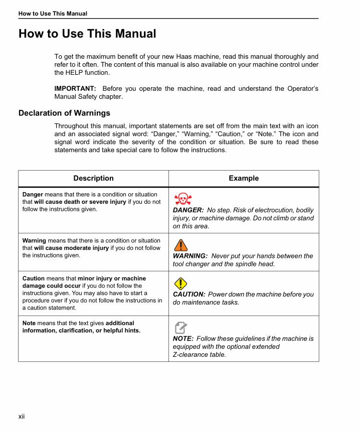
Declaration of WarningsThroughout this manual, important statements are set off from the main text with an iconand an associated signal word: “Danger,” “Warning,” “Caution,” or “Note.” The icon andsignal word indicate the severity of the condition or situation. Be sure to read thesestatements and take special care to follow the instructions.
Description Example
Danger means that there is a condition or situation that will cause death or severe injury if you do not follow the instructions given. DANGER: No step. Risk of electrocution, bodily
injury, or machine damage. Do not climb or stand on this area.
Warning means that there is a condition or situation that will cause moderate injury if you do not follow the instructions given. WARNING: Never put your hands between the
tool changer and the spindle head.
Caution means that minor injury or machine damage could occur if you do not follow the instructions given. You may also have to start a procedure over if you do not follow the instructions in a caution statement.
CAUTION: Power down the machine before you do maintenance tasks.
Note means that the text gives additional information, clarification, or helpful hints.
NOTE: Follow these guidelines if the machine is equipped with the optional extended Z-clearance table.

xiii
Text Conventions Used in this Manual
Description Text Example
Code Block text gives program examples. G00 G90 G54 X0. Y0.;
A Control Button Reference gives the name of a control key or button that you are to press.
Press [CYCLE START].
A File Path describes a sequence of file system directories.
Service > Documents and Software >...
A Mode Reference describes a machine mode. MDI
A Screen Element describes an object on the machine’s display that you interact with.
Select the SYSTEM tab.
System Output describes text that the machine control displays in response to your actions.
PROGRAM END
User Input describes text that you should enter into the machine control.
G04 P1.;
Variable n indicates a range of non-negative integers from 0 to 9.
Dnn represents D00 through D99.

How to Use This Manual
xiv
xv
Contents
User’s Operator Manual and other Online Resources. . . . . . . . . . xiHow to Use This Manual . . . . . . . . . . . . . . . . . . . . . . . . xii
Chapter 1 APL Introduction . . . . . . . . . . . . . . . . . . . . . . . . . . . . . . 11.1 APL Introduction . . . . . . . . . . . . . . . . . . . . . . . . . . . . . 11.2 APL - Overview . . . . . . . . . . . . . . . . . . . . . . . . . . . . . 21.3 APL - Specifications . . . . . . . . . . . . . . . . . . . . . . . . . . . 3
Chapter 2 APL Installation . . . . . . . . . . . . . . . . . . . . . . . . . . . . . . 112.1 Lathe APL - Installation . . . . . . . . . . . . . . . . . . . . . . . . . 11
Chapter 3 APL Operation. . . . . . . . . . . . . . . . . . . . . . . . . . . . . . . 133.1 APL Settings. . . . . . . . . . . . . . . . . . . . . . . . . . . . . . . 13
3.1.1 372 - Parts Loader Type . . . . . . . . . . . . . . . . . . 133.1.2 375 - APL Gripper Type . . . . . . . . . . . . . . . . . . 133.1.3 376 - Light Curtain Enable . . . . . . . . . . . . . . . . . 13
3.2 Jog the APL . . . . . . . . . . . . . . . . . . . . . . . . . . . . . . . 143.3 APL Setup . . . . . . . . . . . . . . . . . . . . . . . . . . . . . . . . 14
3.3.1 Automatic Part Loader - Template. . . . . . . . . . . . . 143.3.2 Automatic Part Loader - Load Part . . . . . . . . . . . . 163.3.3 Automatic Part Loader - Unload Part . . . . . . . . . . . 183.3.4 Automatic Part Loader - APL Mode - Save/Load/New Job 21
3.4 APL Recovery . . . . . . . . . . . . . . . . . . . . . . . . . . . . . . 23
Chapter 4 APL Programming . . . . . . . . . . . . . . . . . . . . . . . . . . . . 254.1 M299 APL / Part Load / or Program End . . . . . . . . . . . . . . . . 25
Chapter 5 APL Maintenance . . . . . . . . . . . . . . . . . . . . . . . . . . . . . 275.1 APL Maintenance . . . . . . . . . . . . . . . . . . . . . . . . . . . . 27
Index . . . . . . . . . . . . . . . . . . . . . . . . . . . . . . . . . . 29

xvi
APL Introduction
1
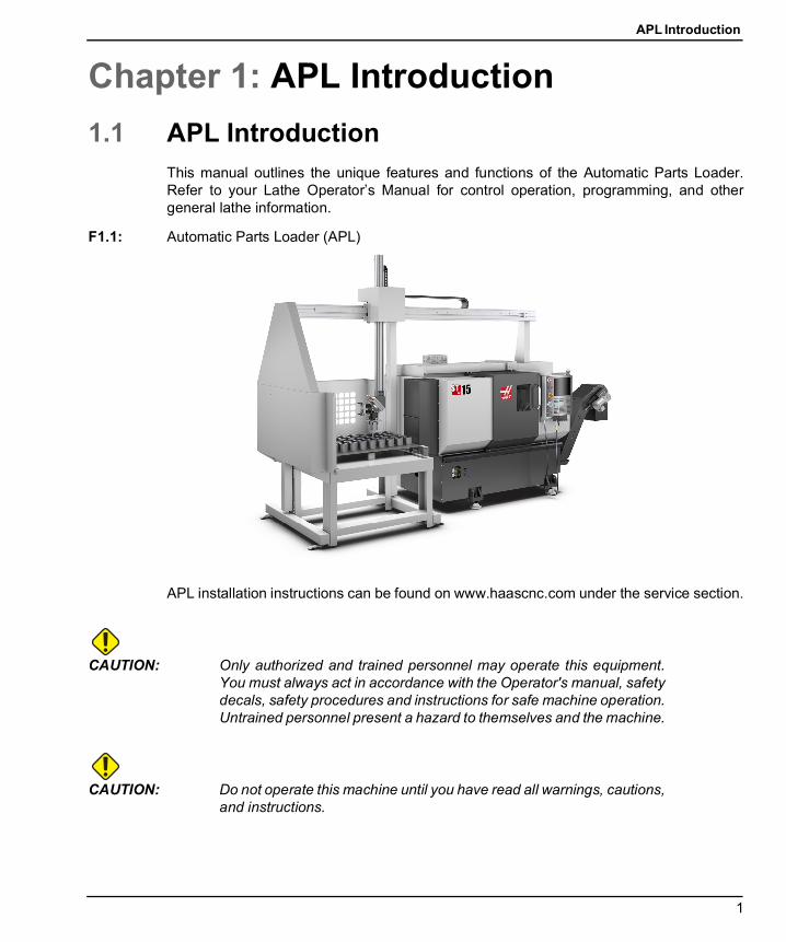
Chapter 1: APL Introduction1.1 APL Introduction
This manual outlines the unique features and functions of the Automatic Parts Loader.Refer to your Lathe Operator’s Manual for control operation, programming, and othergeneral lathe information.
F1.1: Automatic Parts Loader (APL)
APL installation instructions can be found on www.haascnc.com under the service section.
CAUTION: Only authorized and trained personnel may operate this equipment.You must always act in accordance with the Operator's manual, safetydecals, safety procedures and instructions for safe machine operation.Untrained personnel present a hazard to themselves and the machine.
CAUTION: Do not operate this machine until you have read all warnings, cautions,and instructions.
APL - Overview
2
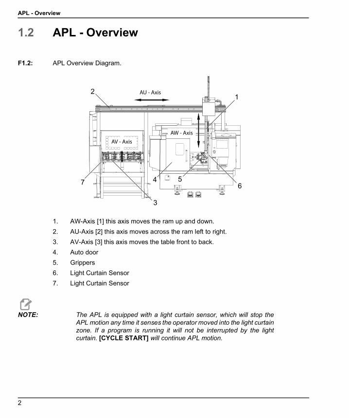
1.2 APL - Overview
F1.2: APL Overview Diagram.
1. AW-Axis [1] this axis moves the ram up and down.2. AU-Axis [2] this axis moves across the ram left to right.3. AV-Axis [3] this axis moves the table front to back.4. Auto door5. Grippers6. Light Curtain Sensor7. Light Curtain Sensor
NOTE: The APL is equipped with a light curtain sensor, which will stop theAPL motion any time it senses the operator moved into the light curtainzone. If a program is running it will not be interrupted by the lightcurtain. [CYCLE START] will continue APL motion.
12
3
4 567
AU - Axis
AW - Axis
AV - Axis
APL Introduction
3
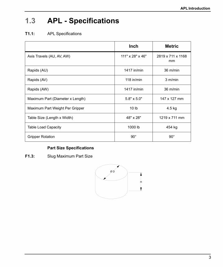
1.3 APL - SpecificationsT1.1: APL Specifications
Part Size Specifications
F1.3: Slug Maximum Part Size
Inch Metric
Axis Travels (AU, AV, AW) 111" x 28" x 46" 2819 x 711 x 1168 mm
Rapids (AU) 1417 in/min 36 m/min
Rapids (AV) 118 in/min 3 m/min
Rapids (AW) 1417 in/min 36 m/min
Maximum Part (Diameter x Length) 5.8" x 5.0" 147 x 127 mm
Maximum Part Weight Per Gripper 10 lb 4.5 kg
Table Size (Length x Width) 48" x 28" 1219 x 711 mm
Table Load Capacity 1000 lb 454 kg
Gripper Rotation 90° 90°
APL - Specifications
4
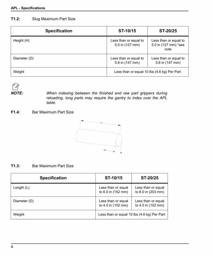
T1.2: Slug Maximum Part Size
NOTE: When indexing between the finished and raw part grippers duringreloading, long parts may require the gantry to index over the APLtable.
F1.4: Bar Maximum Part Size
T1.3: Bar Maximum Part Size
Specification ST-10/15 ST-20/25
Height (H) Less than or equal to 5.0 in (127 mm)
Less than or equal to 5.0 in (127 mm) *see
note
Diameter (D) Less than or equal to 5.8 in (147 mm)
Less than or equal to 5.8 in (147 mm)
Weight Less than or equal 10 lbs (4.6 kg) Per Part
Specification ST-10/15 ST-20/25
Length (L) Less than or equal to 6.0 in (152 mm)
Less than or equal to 8.0 in (203 mm)
Diameter (D) Less than or equal to 4.0 in (102 mm)
Less than or equal to 4.0 in (102 mm)
Weight Less than or equal 10 lbs (4.6 kg) Per Part
APL Introduction
5
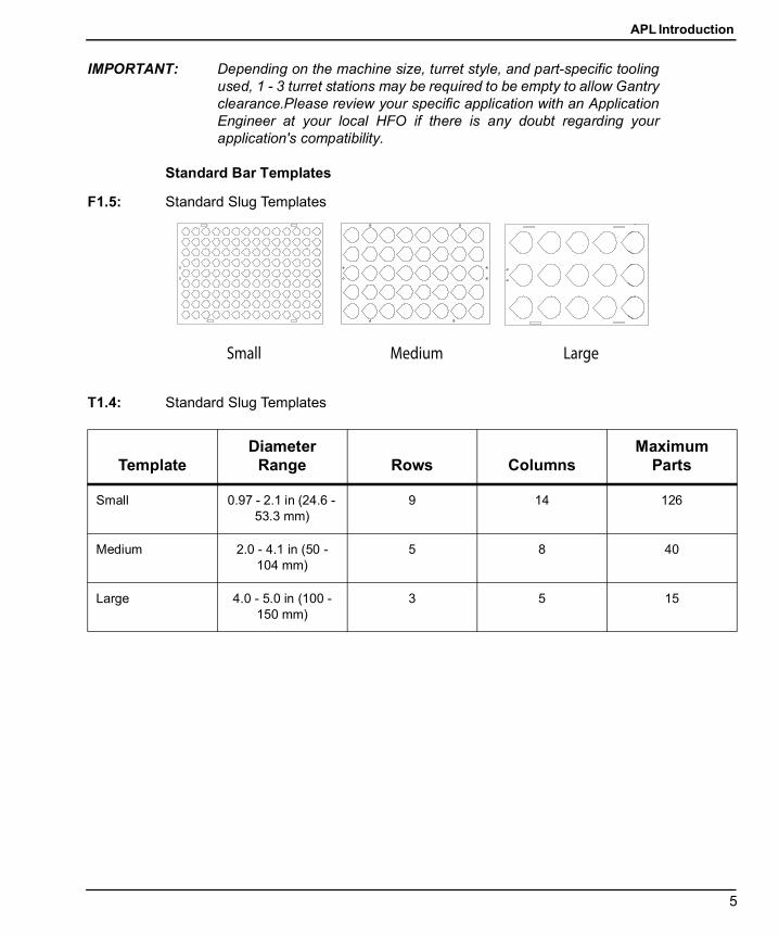
IMPORTANT: Depending on the machine size, turret style, and part-specific toolingused, 1 - 3 turret stations may be required to be empty to allow Gantryclearance.Please review your specific application with an ApplicationEngineer at your local HFO if there is any doubt regarding yourapplication's compatibility.
Standard Bar Templates
F1.5: Standard Slug Templates
T1.4: Standard Slug Templates
TemplateDiameter
Range Rows ColumnsMaximum
Parts
Small 0.97 - 2.1 in (24.6 - 53.3 mm)
9 14 126
Medium 2.0 - 4.1 in (50 - 104 mm)
5 8 40
Large 4.0 - 5.0 in (100 - 150 mm)
3 5 15
Small Medium Large
APL - Specifications
6
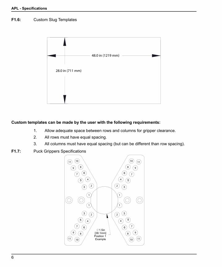
F1.6: Custom Slug Templates
Custom templates can be made by the user with the following requirements:
1. Allow adequate space between rows and columns for gripper clearance.2. All rows must have equal spacing.3. All columns must have equal spacing (but can be different than row spacing).
F1.7: Puck Grippers Specifications
28.0 in (711 mm)
48.0 in (1219 mm)
2
1
4
7
89
1011
1
11
2 2
2
4
44
7
77
8 8
8 9
99
10 10
10 11
1111
APL Introduction
7
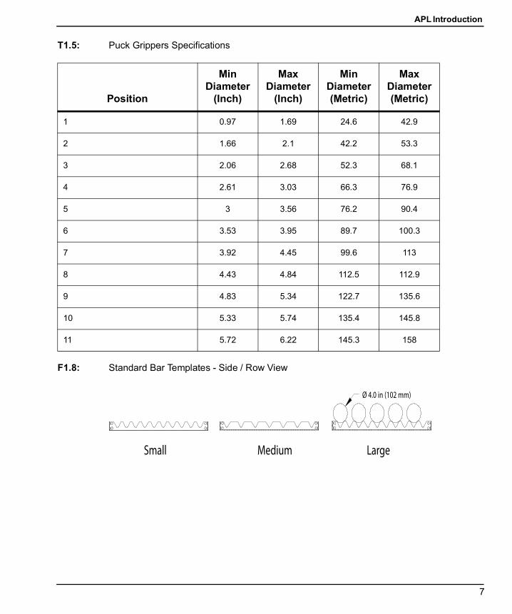
T1.5: Puck Grippers Specifications
F1.8: Standard Bar Templates - Side / Row View
Position
Min Diameter
(Inch)
Max Diameter
(Inch)
Min Diameter (Metric)
Max Diameter (Metric)
1 0.97 1.69 24.6 42.9
2 1.66 2.1 42.2 53.3
3 2.06 2.68 52.3 68.1
4 2.61 3.03 66.3 76.9
5 3 3.56 76.2 90.4
6 3.53 3.95 89.7 100.3
7 3.92 4.45 99.6 113
8 4.43 4.84 112.5 112.9
9 4.83 5.34 122.7 135.6
10 5.33 5.74 135.4 145.8
11 5.72 6.22 145.3 158
Ø 4.0 in (102 mm)
Small Medium Large
APL - Specifications
8
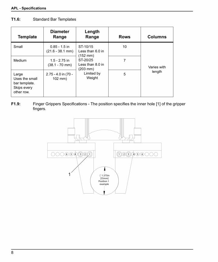
T1.6: Standard Bar Templates
F1.9: Finger Grippers Specifications - The position specifies the inner hole [1] of the gripper fingers.
TemplateDiameter
RangeLength Range Rows Columns
Small 0.85 - 1.5 in (21.6 - 38.1 mm)
ST-10/15Less than 6.0 in (152 mm)ST-20/25Less than 8.0 in (203 mm)
Limited by Weight
10
Varies with length
Medium 1.5 - 2.75 in (38.1 - 70 mm)
7
Large Uses the small bar template. Skips every other row.
2.75 - 4.0 in (70 - 102 mm)
5
1 1.375in[35mm]
Position 1 example
1 12 2 334 45 5 66
APL Introduction
9
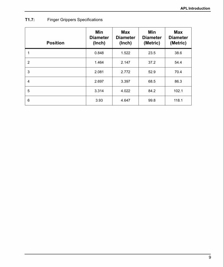
T1.7: Finger Grippers Specifications
Position
Min Diameter
(Inch)
Max Diameter
(Inch)
Min Diameter (Metric)
Max Diameter (Metric)
1 0.848 1.522 23.5 38.6
2 1.464 2.147 37.2 54.4
3 2.081 2.772 52.9 70.4
4 2.697 3.397 68.5 86.3
5 3.314 4.022 84.2 102.1
6 3.93 4.647 99.8 118.1
APL - Specifications
10
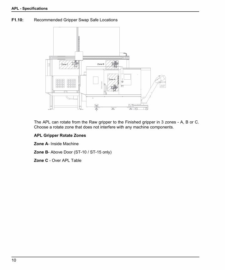
F1.10: Recommended Gripper Swap Safe Locations
The APL can rotate from the Raw gripper to the Finished gripper in 3 zones - A, B or C.Choose a rotate zone that does not interfere with any machine components.
APL Gripper Rotate Zones
Zone A- Inside Machine
Zone B- Above Door (ST-10 / ST-15 only)
Zone C - Over APL Table
Zone A
Zone BZone C
APL Installation
11
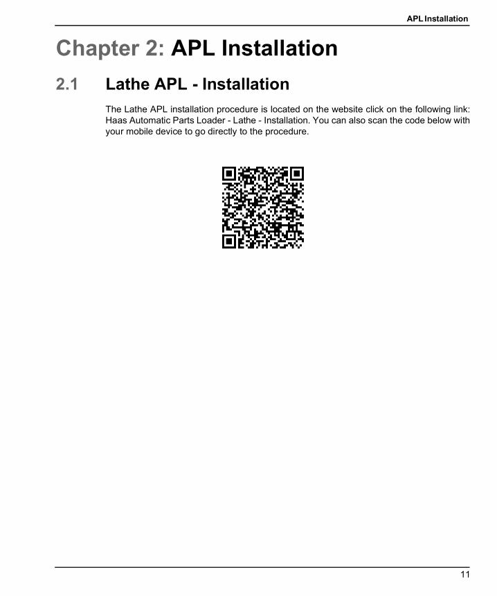
Chapter 2: APL Installation2.1 Lathe APL - Installation
The Lathe APL installation procedure is located on the website click on the following link:Haas Automatic Parts Loader - Lathe - Installation. You can also scan the code below withyour mobile device to go directly to the procedure.

Lathe APL - Installation
12
APL Operation
13
Chapter 3: APL Operation3.1 APL Settings
The following settings affect how the APL operates.
3.1.1 372 - Parts Loader TypeThis setting turns on the Automatic Parts Loader (APL) in [CURRENT COMMANDS] underthe Devices tab. Use this page to set up the APL.
3.1.2 375 - APL Gripper TypeThis setting chooses the type of gripper attached to the Automatic Parts Loader (APL).
APL Gripper has the functionality of gripping raw and finished parts on an outer diameteror inner diameter, in addition to being able to swap between them.
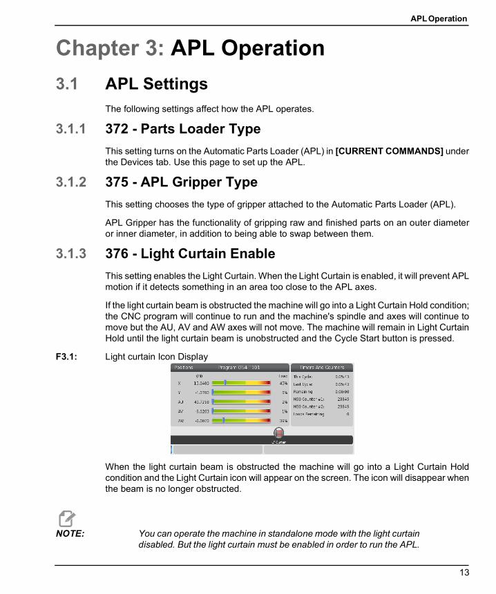
3.1.3 376 - Light Curtain EnableThis setting enables the Light Curtain. When the Light Curtain is enabled, it will prevent APLmotion if it detects something in an area too close to the APL axes.
If the light curtain beam is obstructed the machine will go into a Light Curtain Hold condition;the CNC program will continue to run and the machine's spindle and axes will continue tomove but the AU, AV and AW axes will not move. The machine will remain in Light CurtainHold until the light curtain beam is unobstructed and the Cycle Start button is pressed.
F3.1: Light curtain Icon Display
When the light curtain beam is obstructed the machine will go into a Light Curtain Holdcondition and the Light Curtain icon will appear on the screen. The icon will disappear whenthe beam is no longer obstructed.
NOTE: You can operate the machine in standalone mode with the light curtaindisabled. But the light curtain must be enabled in order to run the APL.
Jog the APL
14
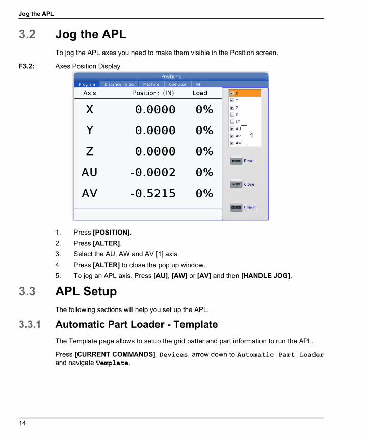
3.2 Jog the APLTo jog the APL axes you need to make them visible in the Position screen.
F3.2: Axes Position Display
1. Press [POSITION].2. Press [ALTER].3. Select the AU, AW and AV [1] axis.4. Press [ALTER] to close the pop up window.5. To jog an APL axis. Press [AU], [AW] or [AV] and then [HANDLE JOG].
3.3 APL SetupThe following sections will help you set up the APL.
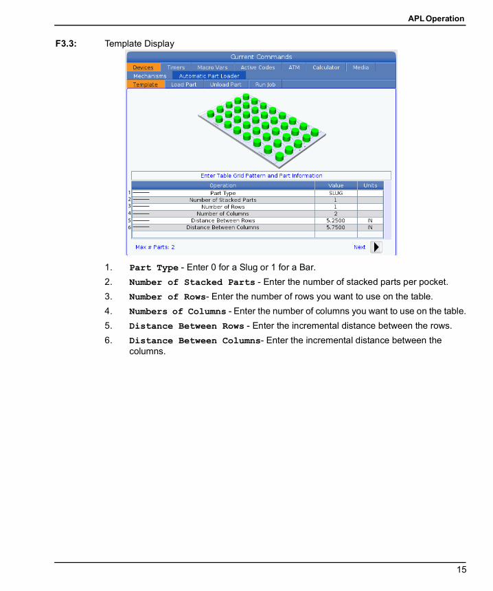
3.3.1 Automatic Part Loader - TemplateThe Template page allows to setup the grid patter and part information to run the APL.
Press [CURRENT COMMANDS], Devices, arrow down to Automatic Part Loaderand navigate Template.
1
APL Operation
15
F3.3: Template Display
1. Part Type - Enter 0 for a Slug or 1 for a Bar.2. Number of Stacked Parts - Enter the number of stacked parts per pocket.3. Number of Rows- Enter the number of rows you want to use on the table.4. Numbers of Columns - Enter the number of columns you want to use on the table.5. Distance Between Rows - Enter the incremental distance between the rows.6. Distance Between Columns- Enter the incremental distance between the
columns.
123456
APL Setup
16
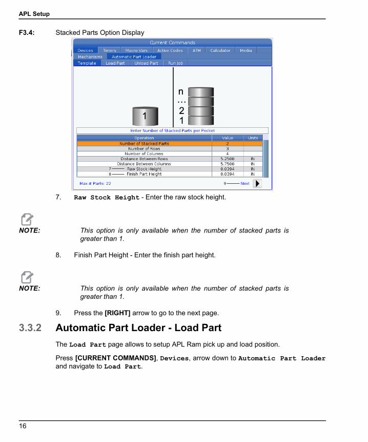
F3.4: Stacked Parts Option Display
7. Raw Stock Height - Enter the raw stock height.
NOTE: This option is only available when the number of stacked parts isgreater than 1.
8. Finish Part Height - Enter the finish part height.
NOTE: This option is only available when the number of stacked parts isgreater than 1.
9. Press the [RIGHT] arrow to go to the next page.
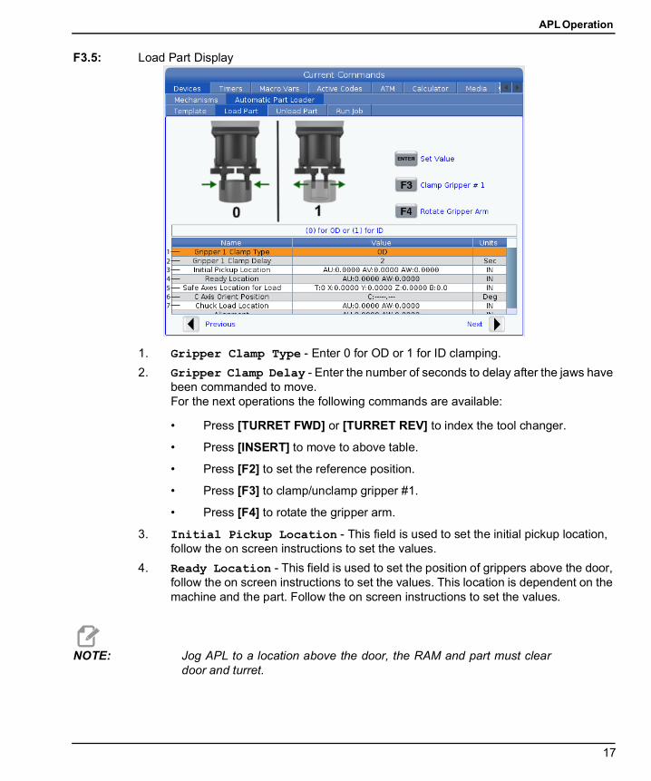
3.3.2 Automatic Part Loader - Load PartThe Load Part page allows to setup APL Ram pick up and load position.
Press [CURRENT COMMANDS], Devices, arrow down to Automatic Part Loaderand navigate to Load Part.
78
9
APL Operation
17
F3.5: Load Part Display
1. Gripper Clamp Type - Enter 0 for OD or 1 for ID clamping.2. Gripper Clamp Delay - Enter the number of seconds to delay after the jaws have
been commanded to move.For the next operations the following commands are available:
• Press [TURRET FWD] or [TURRET REV] to index the tool changer.
• Press [INSERT] to move to above table.
• Press [F2] to set the reference position.
• Press [F3] to clamp/unclamp gripper #1.
• Press [F4] to rotate the gripper arm.
3. Initial Pickup Location - This field is used to set the initial pickup location, follow the on screen instructions to set the values.
4. Ready Location - This field is used to set the position of grippers above the door, follow the on screen instructions to set the values. This location is dependent on the machine and the part. Follow the on screen instructions to set the values.
NOTE: Jog APL to a location above the door, the RAM and part must cleardoor and turret.
1234567
APL Setup
18
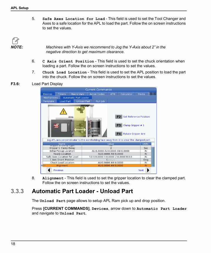
5. Safe Axes Location for Load - This field is used to set the Tool Changer and Axes to a safe location for the APL to load the part. Follow the on screen instructions to set the values.
NOTE: Machines with Y-Axis we recommend to Jog the Y-Axis about 2” in thenegative direction to get maximum clearance.
6. C Axis Orient Position - This field is used to set the chuck orientation when loading a part. Follow the on screen instructions to set the values.
7. Chuck Load Location - This field is used to set the APL position to load the part into the chuck. Follow the on screen instructions to set the values.
F3.6: Load Part Display
8. Alignment - This field is used to set the gripper location to clear the clamped part. Follow the on screen instructions to set the values.
3.3.3 Automatic Part Loader - Unload PartThe Unload Part page allows to setup APL Ram pick up and drop position.
Press [CURRENT COMMANDS], Devices, arrow down to Automatic Part Loaderand navigate to Unload Part.
8
APL Operation
19
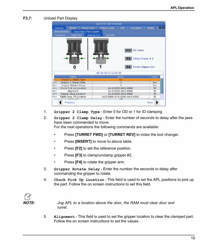
F3.7: Unload Part Display
1. Gripper 2 Clamp Type - Enter 0 for OD or 1 for ID clamping.2. Gripper 2 Clamp Delay - Enter the number of seconds to delay after the jaws
have been commanded to move.For the next operations the following commands are available:
• Press [TURRET FWD] or [TURRET REV] to index the tool changer.
• Press [INSERT] to move to above table.
• Press [F2] to set the reference position.
• Press [F3] to clamp/unclamp gripper #2.
• Press [F4] to rotate the gripper arm.
3. Gripper Rotate Delay - Enter the number the seconds to delay after commanding the gripper to rotate.
4. Chuck Pick Up Location - This field is used to set the APL positions to pick up the part. Follow the on screen instructions to set this field.
NOTE: Jog APL to a location above the door, the RAM must clear door andturret.
5. Alignment - This field is used to set the gripper location to clear the clamped part. Follow the on screen instructions to set the values.
7
123456
APL Setup
20
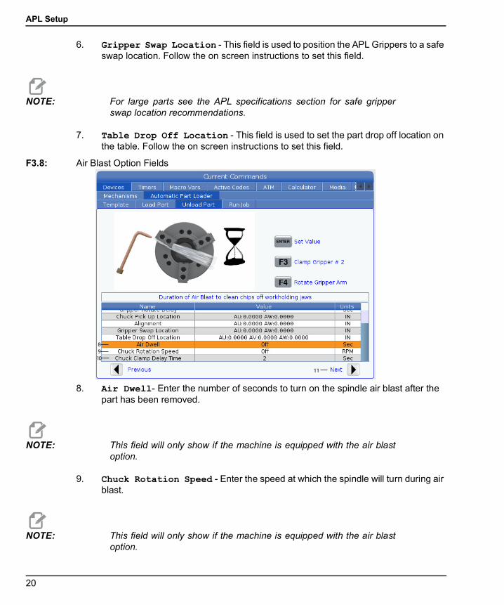
6. Gripper Swap Location - This field is used to position the APL Grippers to a safe swap location. Follow the on screen instructions to set this field.
NOTE: For large parts see the APL specifications section for safe gripperswap location recommendations.
7. Table Drop Off Location - This field is used to set the part drop off location on the table. Follow the on screen instructions to set this field.
F3.8: Air Blast Option Fields
8. Air Dwell- Enter the number of seconds to turn on the spindle air blast after the part has been removed.
NOTE: This field will only show if the machine is equipped with the air blastoption.
9. Chuck Rotation Speed - Enter the speed at which the spindle will turn during air blast.
NOTE: This field will only show if the machine is equipped with the air blastoption.
8910
11
APL Operation
21
10. Chuck Clamp Delay Time - Enter the dwell time before the APL gripper releases the part.
11. Press the [RIGHT] arrow to go to the next page.
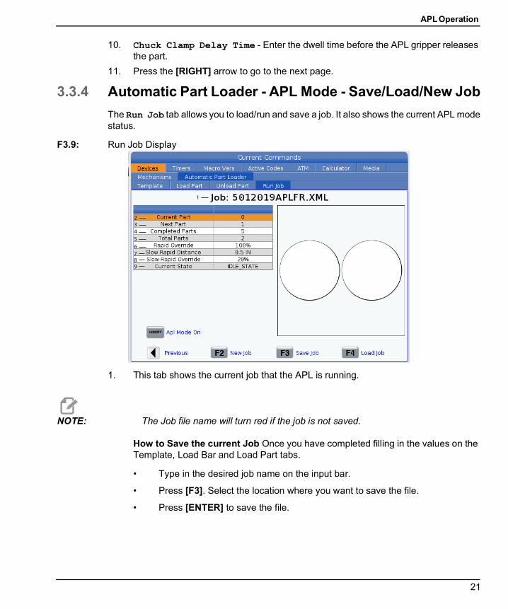
3.3.4 Automatic Part Loader - APL Mode - Save/Load/New JobThe Run Job tab allows you to load/run and save a job. It also shows the current APL modestatus.
F3.9: Run Job Display
1. This tab shows the current job that the APL is running.
NOTE: The Job file name will turn red if the job is not saved.
How to Save the current Job Once you have completed filling in the values on the Template, Load Bar and Load Part tabs.
• Type in the desired job name on the input bar.
• Press [F3]. Select the location where you want to save the file.
• Press [ENTER] to save the file.
2345678
1
9
APL Setup
22
NOTE: The job file is a XML file.
How to Load a Job To load a previous job:
• Press [F4] to load a job.
• Find and highlight the job XML file you wish to load.
• Press [ENTER] to load the file.
How to Start a New Job To start a new job:
• Press [F2].
• A popup window will show “Are you sure you want to clear?
• Press [Y].
NOTE: This will reset the values in the Template, Load Part, Unload Part etc.back to factory values.
2. Current Part- This field can be updated so that the sequence will start at this point.
3. Next Part - This counter shows the next part.4. Completed Parts - This counter shows the amount of completed parts. This field
can be reset with [ORIGIN].5. Total Parts - This field can be changed. The sequence will run until total parts =
completed parts. This would allow of running of a partial table.6. Rapid Override - This shows the current rapid override status.7. Slow Rapid Distance - When the APL is this distance from picking up or dropping
off a part (either from table or spindle) the speed will drop to the Slow Rapid Override setting.
8. Slow Rapid Override - When the APL is the Slow rapid distance from picking up or dropping off a part (either from table or spindle) the speed will drop to this setting.
9. Current State - This shows the APL current state.APL Mode
APL Operation
23
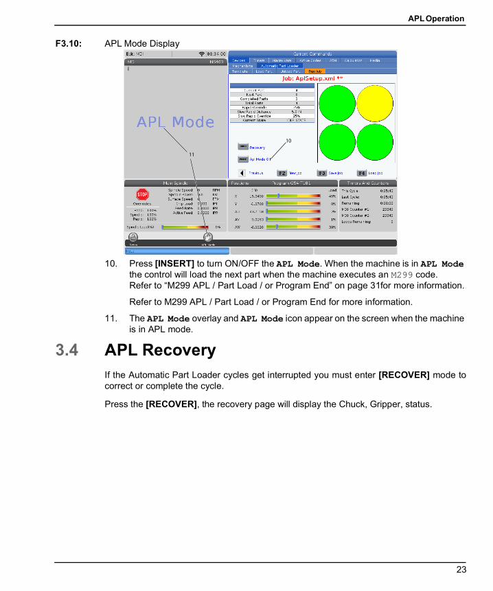
F3.10: APL Mode Display
10. Press [INSERT] to turn ON/OFF the APL Mode. When the machine is in APL Mode the control will load the next part when the machine executes an M299 code. Refer to “M299 APL / Part Load / or Program End” on page 31for more information.
Refer to M299 APL / Part Load / or Program End for more information.
11. The APL Mode overlay and APL Mode icon appear on the screen when the machine is in APL mode.
3.4 APL RecoveryIf the Automatic Part Loader cycles get interrupted you must enter [RECOVER] mode tocorrect or complete the cycle.
Press the [RECOVER], the recovery page will display the Chuck, Gripper, status.
10
11
APL Recovery
24
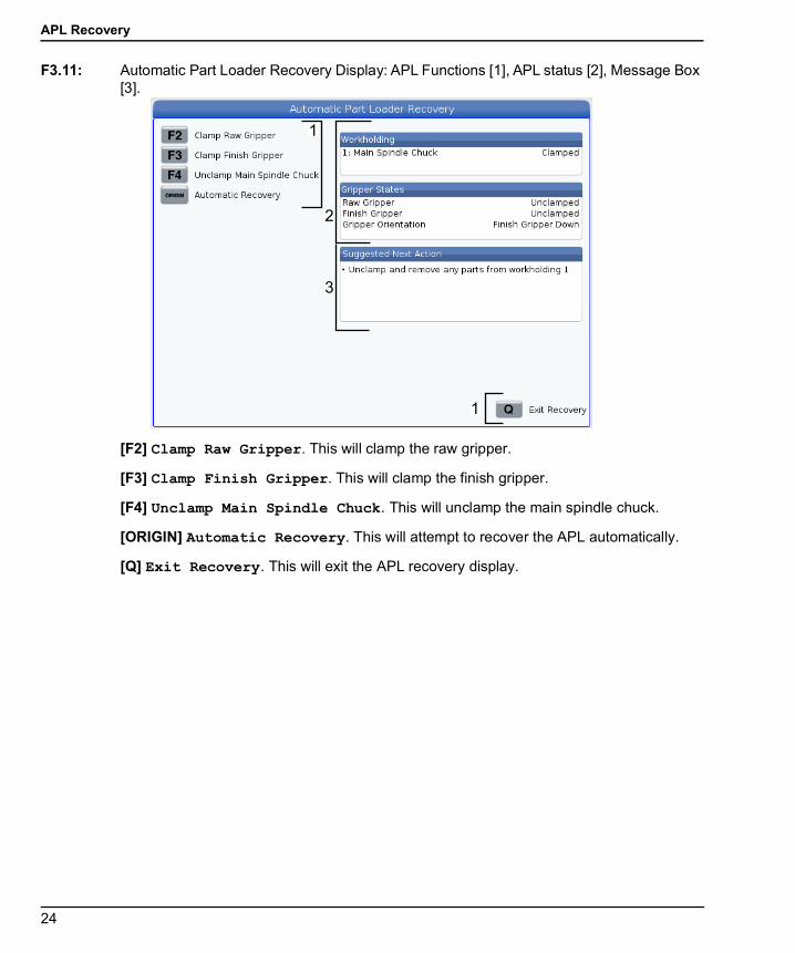
F3.11: Automatic Part Loader Recovery Display: APL Functions [1], APL status [2], Message Box [3].
[F2] Clamp Raw Gripper. This will clamp the raw gripper.
[F3] Clamp Finish Gripper. This will clamp the finish gripper.
[F4] Unclamp Main Spindle Chuck. This will unclamp the main spindle chuck.
[ORIGIN] Automatic Recovery. This will attempt to recover the APL automatically.
[Q] Exit Recovery. This will exit the APL recovery display.
1
2
3
1
APL Programming
25
Chapter 4: APL Programming4.1 M299 APL / Part Load / or Program End
During APL mode, use a M299 instead of an M30 at to have the APL load partsautomatically. Refer to the APL set up section.
When not running in APL mode the M299 takes the place of an M30 or M99 at the end of aprogram.
Also when running in Memory or MDI mode, pressing [CYCLE START] to run the program,the M299 will behave the same as an M30. It will stop and rewind the program back to thebeginning.
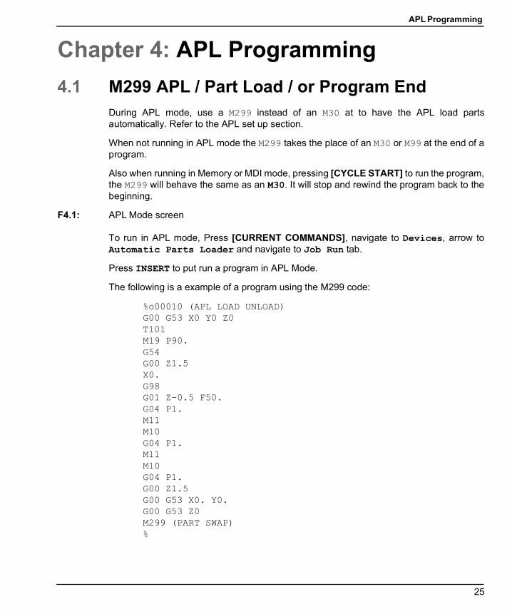
F4.1: APL Mode screen
To run in APL mode, Press [CURRENT COMMANDS], navigate to Devices, arrow toAutomatic Parts Loader and navigate to Job Run tab.
Press INSERT to put run a program in APL Mode.
The following is a example of a program using the M299 code:
%o00010 (APL LOAD UNLOAD)G00 G53 X0 Y0 Z0T101M19 P90.G54G00 Z1.5X0.G98G01 Z-0.5 F50.G04 P1.M11M10G04 P1.M11M10G04 P1.G00 Z1.5G00 G53 X0. Y0.G00 G53 Z0M299 (PART SWAP)%
APL Stop/Resume Feature
26
4.2 APL Stop/Resume FeatureThis feature lets you stop (interrupt) a running part program during an Automatic PartLoading cycle (APL Mode) and then resume normal operation from any part in the program.The APL will not lose part count and it will continue the part load and unload cycle.
NOTE:
1. The part program must be stopped with any program stop command (M00,M01,M02,M30).
2. The APL must reach the “At Ready” position before hitting reset.3. Do not take the control out of “APL Mode”.
After resetting the control an operator may switch to MDI mode, EDIT mode, JOG Mode todo any changes or part inspections as needed. All operation is normal at this point.
When the operator is ready to resume Part Machining in APL Mode. Press [MEMORY] andthen put the cursor on the Tool Callout (e.g. T0505) where you want the program to startfrom. DO not start in the middle of the program since this may cause unintended motion.
With the control still in APL Mode press [CYCLE START] and resume part machining andAPL operation.
APL Maintenance
27
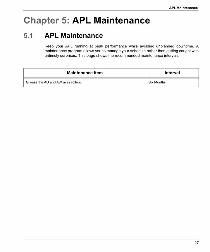
Chapter 5: APL Maintenance5.1 APL Maintenance
Keep your APL running at peak performance while avoiding unplanned downtime. Amaintenance program allows you to manage your schedule rather than getting caught withuntimely surprises. This page shows the recommended maintenance intervals.
Maintenance Item Interval
Grease the AU and AW axes rollers. Six Months

APL Maintenance
28
29
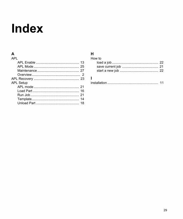
Index
AAPL
APL Enable ...................................... 13APL Mode ........................................ 25Maintenance..................................... 27Overview........................................... 2
APL Recovery ........................................ 23APL Setup
APL mode ........................................ 21Load Part ......................................... 16Run Job........................................... 21Template.......................................... 14Unload Part ...................................... 18
HHow to
load a job......................................... 22save current job ................................ 21start a new job .................................. 22
Iinstallation ............................................. 11

30