h3c s7500e series ethernet switches installation · pdf fileh3c s7500e series ethernet...
TRANSCRIPT
H3C S7500E Series Ethernet Switches
Installation Manual
Hangzhou H3C Technologies Co., Ltd.
http://www.h3c.com
Manual Version: T2-080406-20080725-C-1.04

Copyright © 2007-2008, Hangzhou H3C Technologies Co., Ltd.
All Rights Reserved
No part of this manual may be reproduced or transmitted in any form or by any means without prior written consent of Hangzhou H3C Technologies Co., Ltd.
Trademarks
H3C, , Aolynk, , H3Care,
, TOP G, , IRF, NetPilot, Neocean, NeoVTL, SecPro, SecPoint, SecEngine, SecPath, Comware, Secware, Storware, NQA, VVG, V2G, VnG, PSPT, XGbus, N-Bus, TiGem, InnoVision and HUASAN are trademarks of Hangzhou H3C Technologies Co., Ltd.
All other trademarks that may be mentioned in this manual are the property of their respective owners.
Notice
The information in this document is subject to change without notice. Every effort has been made in the preparation of this document to ensure accuracy of the contents, but all statements, information, and recommendations in this document do not constitute the warranty of any kind, express or implied.
Technical Support
http://www.h3c.com
About This Manual
Organization
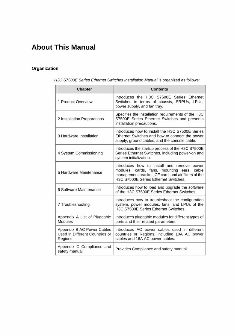
H3C S7500E Series Ethernet Switches Installation Manual is organized as follows:
Chapter Contents
1 Product Overview Introduces the H3C S7500E Series Ethernet Switches in terms of chassis, SRPUs, LPUs, power supply, and fan tray.
2 Installation Preparations Specifies the installation requirements of the H3C S7500E Series Ethernet Switches and presents installation precautions.
3 Hardware Installation Introduces how to install the H3C S7500E Series Ethernet Switches and how to connect the power supply, ground cables, and the console cable.
4 System Commissioning Introduces the startup process of the H3C S7500E Series Ethernet Switches, including power-on and system initialization.
5 Hardware Maintenance
Introduces how to install and remove power modules, cards, fans, mounting ears, cable management bracket, CF card, and air filters of the H3C S7500E Series Ethernet Switches.
6 Software Maintenance Introduces how to load and upgrade the software of the H3C S7500E Series Ethernet Switches.
7 Troubleshooting Introduces how to troubleshoot the configuration system, power modules, fans, and LPUs of the H3C S7500E Series Ethernet Switches.
Appendix A List of Pluggable Modules
Introduces pluggable modules for different types of ports and their related parameters.
Appendix B AC Power Cables Used in Different Countries or Regions
Introduces AC power cables used in different countries or Regions, including 10A AC power cables and 16A AC power cables.
Appendix C Compliance and safety manual Provides Compliance and safety manual
Conventions
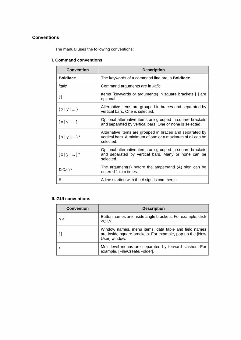
The manual uses the following conventions:
I. Command conventions
Convention Description
Boldface The keywords of a command line are in Boldface.
italic Command arguments are in italic.
[ ] Items (keywords or arguments) in square brackets [ ] are optional.
{ x | y | ... } Alternative items are grouped in braces and separated by vertical bars. One is selected.
[ x | y | ... ] Optional alternative items are grouped in square brackets and separated by vertical bars. One or none is selected.
{ x | y | ... } * Alternative items are grouped in braces and separated by vertical bars. A minimum of one or a maximum of all can be selected.
[ x | y | ... ] * Optional alternative items are grouped in square brackets and separated by vertical bars. Many or none can be selected.
&<1-n> The argument(s) before the ampersand (&) sign can be entered 1 to n times.
# A line starting with the # sign is comments.
II. GUI conventions
Convention Description
< > Button names are inside angle brackets. For example, click <OK>.
[ ] Window names, menu items, data table and field names are inside square brackets. For example, pop up the [New User] window.
/ Multi-level menus are separated by forward slashes. For example, [File/Create/Folder].
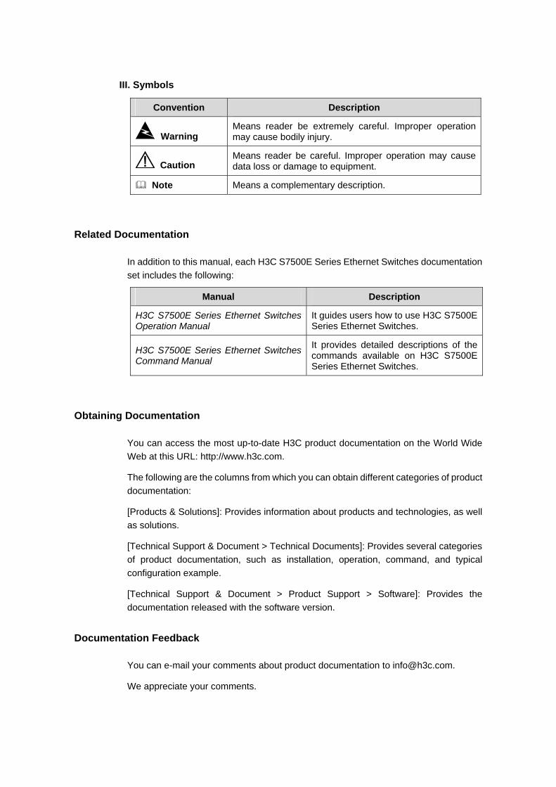
III. Symbols
Convention Description
Warning Means reader be extremely careful. Improper operation may cause bodily injury.
Caution Means reader be careful. Improper operation may cause data loss or damage to equipment.
Note Means a complementary description.
Related Documentation
In addition to this manual, each H3C S7500E Series Ethernet Switches documentation set includes the following:
Manual Description
H3C S7500E Series Ethernet Switches Operation Manual
It guides users how to use H3C S7500E Series Ethernet Switches.
H3C S7500E Series Ethernet Switches Command Manual
It provides detailed descriptions of the commands available on H3C S7500E Series Ethernet Switches.
Obtaining Documentation
You can access the most up-to-date H3C product documentation on the World Wide Web at this URL: http://www.h3c.com.
The following are the columns from which you can obtain different categories of product documentation:
[Products & Solutions]: Provides information about products and technologies, as well as solutions.
[Technical Support & Document > Technical Documents]: Provides several categories of product documentation, such as installation, operation, command, and typical configuration example.
[Technical Support & Document > Product Support > Software]: Provides the documentation released with the software version.
Documentation Feedback
You can e-mail your comments about product documentation to [email protected].
We appreciate your comments.

Environmental Protection
This product has been designed to comply with the requirements on environmental protection. For the proper storage, use and disposal of this product, national laws and regulations must be observed.
Installation Manual H3C S7500E Series Ethernet Switches Table of Contents
i
Table of Contents
Chapter 1 Product Overview ........................................................................................................ 1-1 1.1 Introduction ........................................................................................................................ 1-1 1.2 Physical Description of the S7500E Series ....................................................................... 1-1
1.2.1 Chassis and Slots ................................................................................................... 1-1 1.2.2 Backplane................................................................................................................ 1-9 1.2.3 Power Supply System ............................................................................................. 1-9 1.2.4 Fan Tray ................................................................................................................ 1-18 1.2.5 Air Filter ................................................................................................................. 1-19
1.3 SRPUs ............................................................................................................................. 1-19 1.3.1 SRPU Types.......................................................................................................... 1-19 1.3.2 LSQ1MPUA0 SRPU.............................................................................................. 1-20 1.3.3 Dedicated S7503E-S SRPU-LSQ1CGP24TSC0.................................................. 1-24 1.3.4 Salience VI-10GE SRPU-LSQ1SRP2XB0............................................................ 1-28 1.3.5 Salience VI SRPU-LSQ1SRPB0........................................................................... 1-33 1.3.6 Salience VI-Turbo SRPU-LSQ1SRP1CB0 ........................................................... 1-36 1.3.7 Salience VI-Lite SRPU-LSQ1MPUB0 ................................................................... 1-40 1.3.8 Salience VI-Plus SRPU-LSQ1SRPD0 .................................................................. 1-44 1.3.9 Salience VI-GE SRPU-LSQ1SRP12GB0 ............................................................. 1-47
1.4 LPUs ................................................................................................................................ 1-52 1.4.1 LSQ1FP48SA0...................................................................................................... 1-52 1.4.2 LSQ1FV48SA0...................................................................................................... 1-53 1.4.3 LSQ1GP12EA0 ..................................................................................................... 1-54 1.4.4 LSQ1GP12SC0..................................................................................................... 1-55 1.4.5 LSQ1GP24SC0..................................................................................................... 1-56 1.4.6 LSQ1GP48SC0..................................................................................................... 1-57 1.4.7 LSQ1GT24SC0 ..................................................................................................... 1-58 1.4.8 LSQ1GV48SA0 ..................................................................................................... 1-59 1.4.9 LSQ1GV48SC0..................................................................................................... 1-60 1.4.10 LSQ1P24XGSC0 ................................................................................................ 1-61 1.4.11 LSQ1T24XGSC0................................................................................................. 1-63 1.4.12 LSQ1TGX1EA0................................................................................................... 1-64 1.4.13 LSQ1TGX2SC0................................................................................................... 1-65 1.4.14 LSQ1GP24TSC0................................................................................................. 1-66 1.4.15 LSQ1GV40PSC0 ................................................................................................ 1-68 1.4.16 LSQ1PT4PSC0 ................................................................................................... 1-69 1.4.17 LSQ1PT8PSC0 ................................................................................................... 1-71 1.4.18 LSQ1PT16PSC0 ................................................................................................. 1-73
1.5 Ordering Information for the S7500E Series ................................................................... 1-74

Installation Manual H3C S7500E Series Ethernet Switches Table of Contents
ii
1.5.1 Purchasing a Switch.............................................................................................. 1-74 1.5.2 Purchasing SRPUs ............................................................................................... 1-76 1.5.3 Purchasing LPUs................................................................................................... 1-76 1.5.4 Purchasing Optical Modules ................................................................................. 1-77 1.5.5 Purchasing Air Filters ............................................................................................ 1-77 1.5.6 Purchasing Fan Trays ........................................................................................... 1-78
Installation Manual H3C S7500E Series Ethernet Switches Chapter 1 Product Overview
1-1
Chapter 1 Product Overview
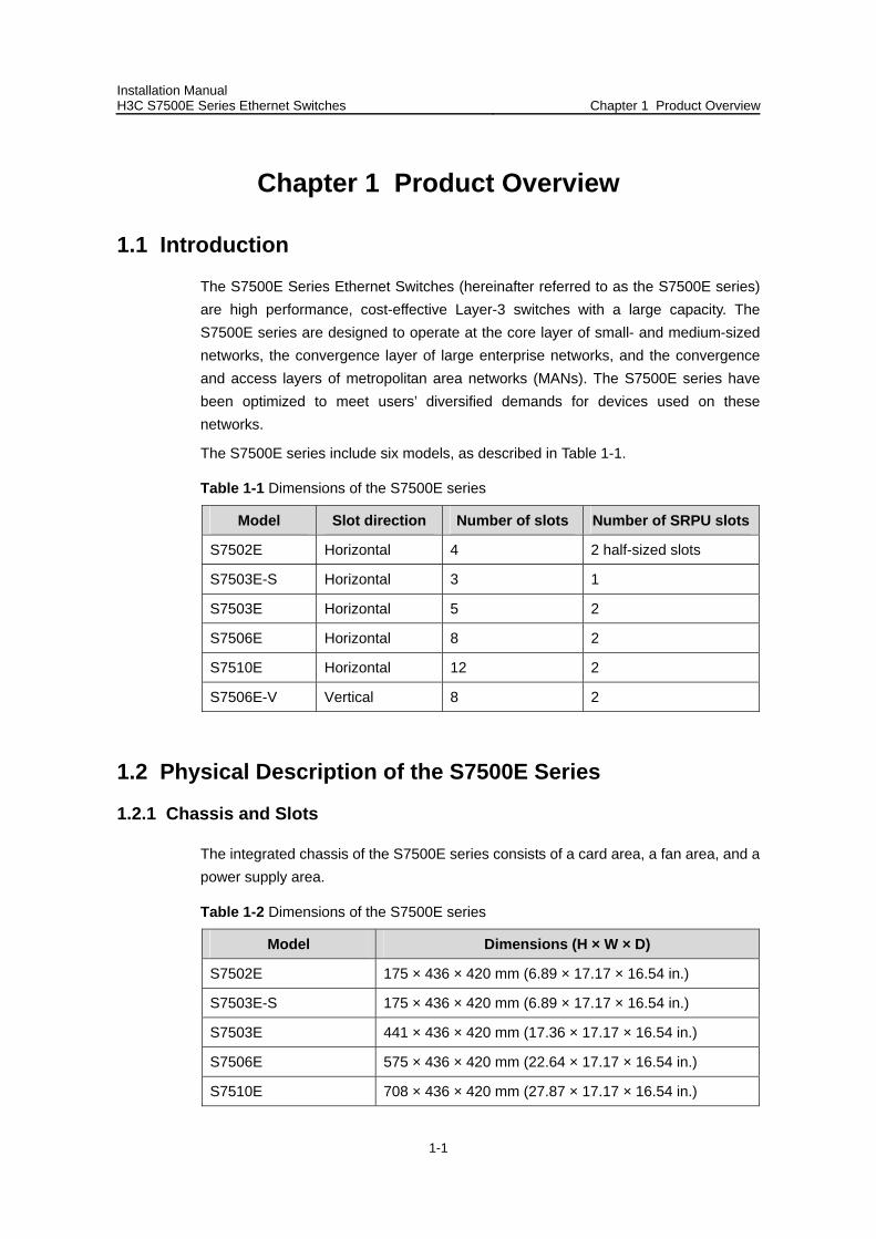
1.1 Introduction
The S7500E Series Ethernet Switches (hereinafter referred to as the S7500E series) are high performance, cost-effective Layer-3 switches with a large capacity. The S7500E series are designed to operate at the core layer of small- and medium-sized networks, the convergence layer of large enterprise networks, and the convergence and access layers of metropolitan area networks (MANs). The S7500E series have been optimized to meet users’ diversified demands for devices used on these networks.
The S7500E series include six models, as described in Table 1-1.
Table 1-1 Dimensions of the S7500E series
Model Slot direction Number of slots Number of SRPU slots
S7502E Horizontal 4 2 half-sized slots
S7503E-S Horizontal 3 1
S7503E Horizontal 5 2
S7506E Horizontal 8 2
S7510E Horizontal 12 2
S7506E-V Vertical 8 2
1.2 Physical Description of the S7500E Series
1.2.1 Chassis and Slots
The integrated chassis of the S7500E series consists of a card area, a fan area, and a power supply area.
Table 1-2 Dimensions of the S7500E series
Model Dimensions (H × W × D)
S7502E 175 × 436 × 420 mm (6.89 × 17.17 × 16.54 in.)
S7503E-S 175 × 436 × 420 mm (6.89 × 17.17 × 16.54 in.)
S7503E 441 × 436 × 420 mm (17.36 × 17.17 × 16.54 in.)
S7506E 575 × 436 × 420 mm (22.64 × 17.17 × 16.54 in.)
S7510E 708 × 436 × 420 mm (27.87 × 17.17 × 16.54 in.)
Installation Manual H3C S7500E Series Ethernet Switches Chapter 1 Product Overview
1-2
Model Dimensions (H × W × D)
S7506E-V 930 × 436 × 420 mm (36.61 × 17.17 × 16.54 in.)
Note:
The backplane, switching & routing processing unit (SRPU), power modules, and fan tray are all required parts of the S7500E series.
SRPUs and line processing units (LPUs) are distinguished by their edge colors. SRPUs have pink edges while LPUs have purple edges. SRPUs must be inserted in pink slots while LPUs must be inserted in purple slots.
The power supply of the S7500E series can be AC or DC, depending on the actual requirement. However, it is forbidden to insert different power modules into one S7500E Ethernet switch.
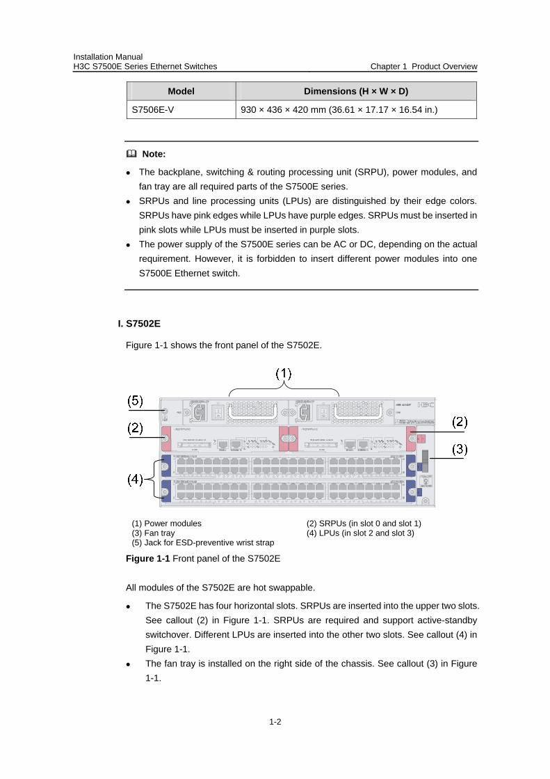
I. S7502E
Figure 1-1 shows the front panel of the S7502E.
(1) Power modules (2) SRPUs (in slot 0 and slot 1) (3) Fan tray (4) LPUs (in slot 2 and slot 3) (5) Jack for ESD-preventive wrist strap
Figure 1-1 Front panel of the S7502E
All modules of the S7502E are hot swappable.
The S7502E has four horizontal slots. SRPUs are inserted into the upper two slots. See callout (2) in Figure 1-1. SRPUs are required and support active-standby switchover. Different LPUs are inserted into the other two slots. See callout (4) in Figure 1-1.
The fan tray is installed on the right side of the chassis. See callout (3) in Figure 1-1.
Installation Manual H3C S7500E Series Ethernet Switches Chapter 1 Product Overview
1-3
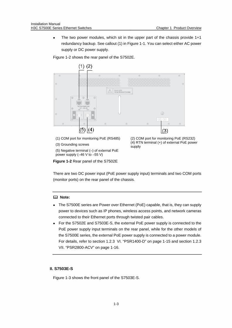
The two power modules, which sit in the upper part of the chassis provide 1+1 redundancy backup. See callout (1) in Figure 1-1. You can select either AC power supply or DC power supply.
Figure 1-2 shows the rear panel of the S7502E.
(1) COM port for monitoring PoE (RS485) (2) COM port for monitoring PoE (RS232)
(3) Grounding screws (4) RTN terminal (+) of external PoE power supply
(5) Negative terminal (–) of external PoE power supply (–46 V to –55 V)
Figure 1-2 Rear panel of the S7502E
There are two DC power input (PoE power supply input) terminals and two COM ports (monitor ports) on the rear panel of the chassis.
Note:
The S7500E series are Power over Ethernet (PoE) capable, that is, they can supply power to devices such as IP phones, wireless access points, and network cameras connected to their Ethernet ports through twisted pair cables.
For the S7502E and S7503E-S, the external PoE power supply is connected to the PoE power supply input terminals on the rear panel, while for the other models of the S7500E series, the external PoE power supply is connected to a power module. For details, refer to section 1.2.3 VI. “PSR1400-D” on page 1-15 and section 1.2.3 VII. “PSR2800-ACV” on page 1-16.
II. S7503E-S
Figure 1-3 shows the front panel of the S7503E-S.

Installation Manual H3C S7500E Series Ethernet Switches Chapter 1 Product Overview
1-4
(1) Power modules (2) SRPUs (in slot 0) (3) Fan tray (4) LPUs (in slot 1 and slot 2) (5) Jack for ESD-preventive wrist strap
Figure 1-3 Front panel of the S7503E-S
All modules of the S7503E-S are hot swappable.
The S7503E-S has three horizontal slots. SRPUs are inserted into the upper slot. See callout (2) in Figure 1-3. Dedicated S7503E-S SRPUs are required. Different LPUs are inserted into the other two slots. See callout (4) in Figure 1-3.
The fan tray is installed on the right side of the chassis. See callout (3) in Figure 1-3.
The two power modules, which sit in the upper part of the chassis provide 1+1 redundancy backup. See callout (1) in Figure 1-3. You can select either AC power supply or DC power supply.
Figure 1-4 shows the rear panel of the S7503E-S.
(1) COM port for monitoring PoE (RS485) (2) COM port for monitoring PoE (RS232)
(3) Grounding screws (4) RTN terminal (+) of external PoE power supply
(5) Negative terminal (–) of external PoE power supply (–46 V to –55 V)
Figure 1-4 Rear panel of the S7503E-S
Installation Manual H3C S7500E Series Ethernet Switches Chapter 1 Product Overview
1-5
There are two DC power input (PoE power supply input) terminals and two COM ports (monitor ports) on the rear panel of the chassis.
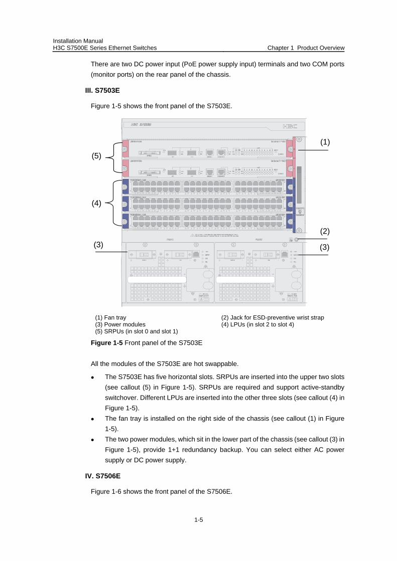
III. S7503E
Figure 1-5 shows the front panel of the S7503E.
(1)
(3)
(4)
(5)
(2)
(3)
(1) Fan tray (2) Jack for ESD-preventive wrist strap (3) Power modules (4) LPUs (in slot 2 to slot 4) (5) SRPUs (in slot 0 and slot 1)
Figure 1-5 Front panel of the S7503E
All the modules of the S7503E are hot swappable.
The S7503E has five horizontal slots. SRPUs are inserted into the upper two slots (see callout (5) in Figure 1-5). SRPUs are required and support active-standby switchover. Different LPUs are inserted into the other three slots (see callout (4) in Figure 1-5).
The fan tray is installed on the right side of the chassis (see callout (1) in Figure 1-5).
The two power modules, which sit in the lower part of the chassis (see callout (3) in Figure 1-5), provide 1+1 redundancy backup. You can select either AC power supply or DC power supply.
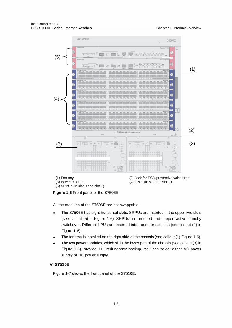
IV. S7506E
Figure 1-6 shows the front panel of the S7506E.
Installation Manual H3C S7500E Series Ethernet Switches Chapter 1 Product Overview
1-6
(1)
(3)
(4)
(5)
(2)
(3)
(1) Fan tray (2) Jack for ESD-preventive wrist strap (3) Power module (4) LPUs (in slot 2 to slot 7) (5) SRPUs (in slot 0 and slot 1)
Figure 1-6 Front panel of the S7506E
All the modules of the S7506E are hot swappable.
The S7506E has eight horizontal slots. SRPUs are inserted in the upper two slots (see callout (5) in Figure 1-6). SRPUs are required and support active-standby switchover. Different LPUs are inserted into the other six slots (see callout (4) in Figure 1-6).
The fan tray is installed on the right side of the chassis (see callout (1) Figure 1-6). The two power modules, which sit in the lower part of the chassis (see callout (3) in
Figure 1-6), provide 1+1 redundancy backup. You can select either AC power supply or DC power supply.
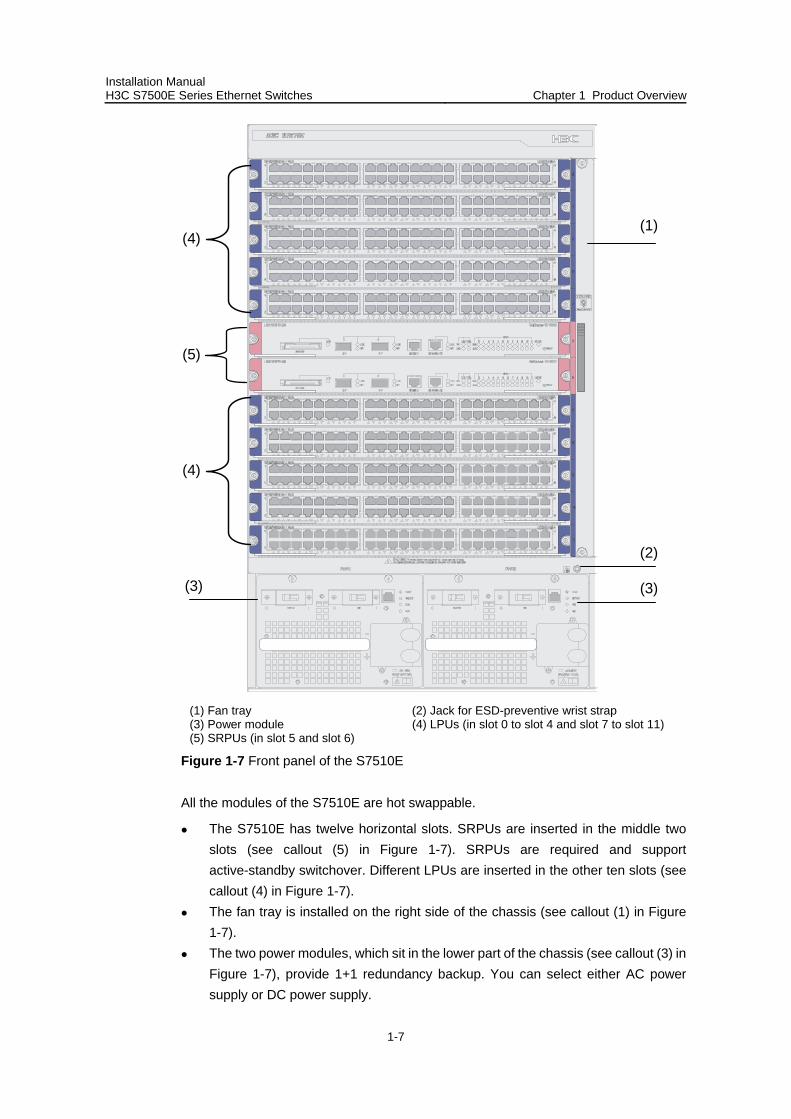
V. S7510E
Figure 1-7 shows the front panel of the S7510E.
Installation Manual H3C S7500E Series Ethernet Switches Chapter 1 Product Overview
1-7
(3)
(5)
(4)
(4)
(3)
(1)
(2)
(1) Fan tray (2) Jack for ESD-preventive wrist strap (3) Power module (4) LPUs (in slot 0 to slot 4 and slot 7 to slot 11) (5) SRPUs (in slot 5 and slot 6)
Figure 1-7 Front panel of the S7510E
All the modules of the S7510E are hot swappable.
The S7510E has twelve horizontal slots. SRPUs are inserted in the middle two slots (see callout (5) in Figure 1-7). SRPUs are required and support active-standby switchover. Different LPUs are inserted in the other ten slots (see callout (4) in Figure 1-7).
The fan tray is installed on the right side of the chassis (see callout (1) in Figure 1-7).
The two power modules, which sit in the lower part of the chassis (see callout (3) in Figure 1-7), provide 1+1 redundancy backup. You can select either AC power supply or DC power supply.
Installation Manual H3C S7500E Series Ethernet Switches Chapter 1 Product Overview
1-8
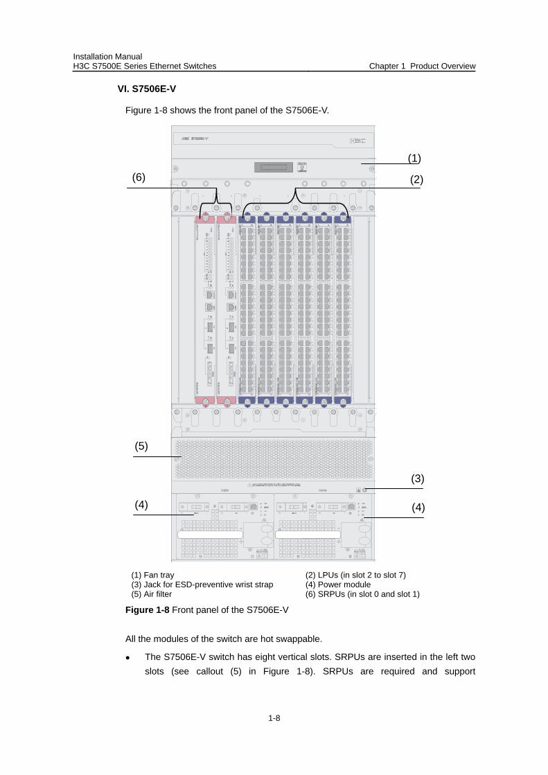
VI. S7506E-V
Figure 1-8 shows the front panel of the S7506E-V.
(1)
(4)
(2)(6)
(3)
(4)
(5)
(1) Fan tray (2) LPUs (in slot 2 to slot 7) (3) Jack for ESD-preventive wrist strap (4) Power module (5) Air filter (6) SRPUs (in slot 0 and slot 1)
Figure 1-8 Front panel of the S7506E-V
All the modules of the switch are hot swappable.
The S7506E-V switch has eight vertical slots. SRPUs are inserted in the left two slots (see callout (5) in Figure 1-8). SRPUs are required and support
Installation Manual H3C S7500E Series Ethernet Switches Chapter 1 Product Overview
1-9
active-standby switchover. Different LPUs are inserted in the other six slots (see callout (2) in Figure 1-8).
The fan tray is installed above the SRPUs and LPUs (see callout (1) in Figure 1-8) and the air flows up from the bottom.
The two power modules, which sit in the lower part of the chassis (see callout (3) in Figure 1-8), provide 1+1 redundancy backup. You can select either AC power supply or DC power supply.
1.2.2 Backplane
The backplane in the integrated chassis of the S7500E series implements high-speed data exchange as well as management & control signal exchange between SRPUs and LPUs.
The backplane mainly provides the following functions:
Interconnection between cards Card hot-swapping Automatic slot recognition Automatic chassis type recognition Distributed power supply to the system. The S7506E-V has two backplanes:
signal backplane and power supply backplane. The power supply backplane is connected to the power modules and is also connected to the signal backplane with an internal cable.
Connection of the signal cable that monitors the fan tray and power supply
1.2.3 Power Supply System
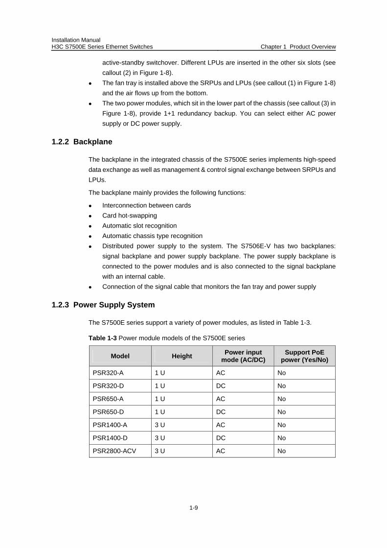
The S7500E series support a variety of power modules, as listed in Table 1-3.
Table 1-3 Power module models of the S7500E series
Model Height Power input mode (AC/DC)
Support PoE power (Yes/No)
PSR320-A 1 U AC No
PSR320-D 1 U DC No
PSR650-A 1 U AC No
PSR650-D 1 U DC No
PSR1400-A 3 U AC No
PSR1400-D 3 U DC No
PSR2800-ACV 3 U AC No
Installation Manual H3C S7500E Series Ethernet Switches Chapter 1 Product Overview
1-10
Table 1-4 Features of power modules
Feature Description
Protection functions Support input under-voltage protection, output over-voltage protection, short-circuit protection, over-current protection, and overheat protection
1+1 hot backup support Support 1 + 1 hot backup and current sharing
Hot swap support Support hot swap with the power switch turned off while the device is in operation
Typically, the S7502E and the S7503E-S use 1U power modules, while the other models of the S7500E series use 3U power modules.
The S7500E series support a large variety of card types, and system power consumption of a switch varies with different types of cards in use. You can choose an appropriate power module model for your switch based on its system power consumption.
H3C has designed a power module adapter, PWR-SPA, to allow flexible power module options to suit different system power consumption characteristics.
You can use PSR650 power modules in combination with PWR-SPA power module adapters to power a switch with system power consumption lower than 650 W, instead of using heavy-duty power modules like the PSR1400 or PSR2800.
The system power consumption of a switch is determined by its SRPUs, LPUs, and fan tray. Specifically, the system power consumption of a switch is equal to the power consumption of its SRPUs, LPUs, and fan tray put together.
For how to install power modules and power module adapters, refer to section 5.2 "Removing and Installing a Power Module."
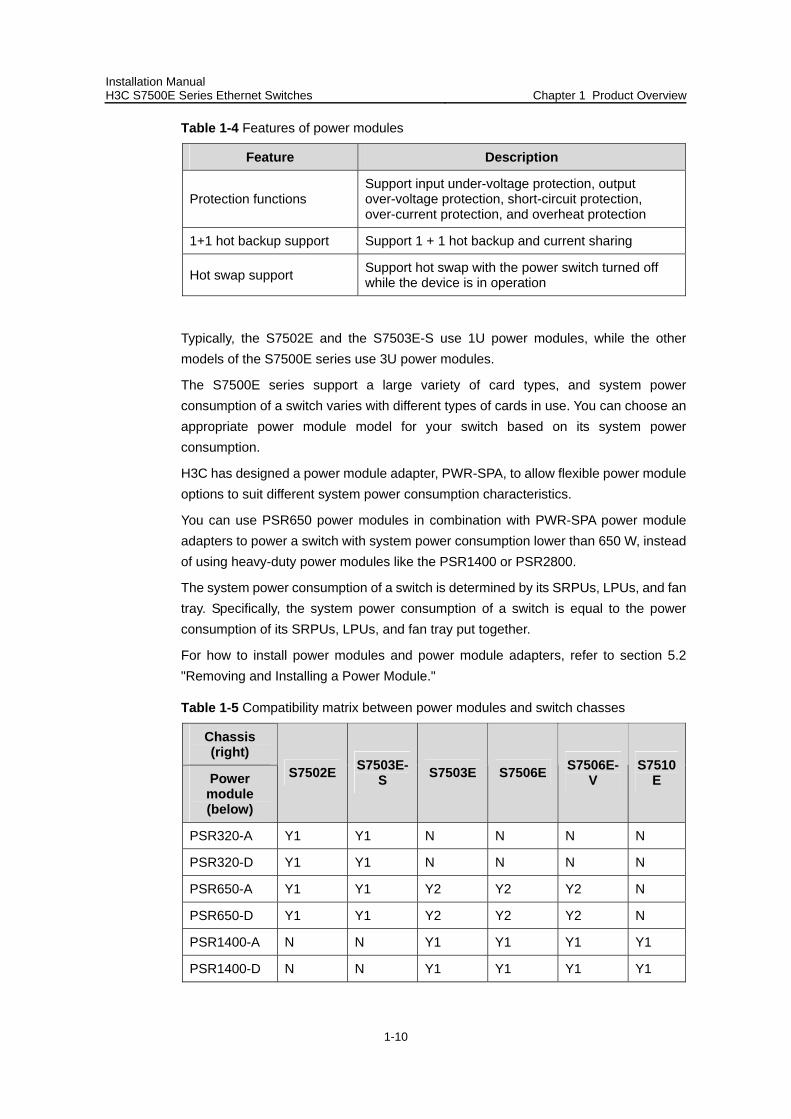
Table 1-5 Compatibility matrix between power modules and switch chasses
Chassis (right)
Power module (below)
S7502E S7503E-S S7503E S7506E S7506E-
V S7510
E
PSR320-A Y1 Y1 N N N N
PSR320-D Y1 Y1 N N N N
PSR650-A Y1 Y1 Y2 Y2 Y2 N
PSR650-D Y1 Y1 Y2 Y2 Y2 N
PSR1400-A N N Y1 Y1 Y1 Y1
PSR1400-D N N Y1 Y1 Y1 Y1
Installation Manual H3C S7500E Series Ethernet Switches Chapter 1 Product Overview
1-11
Chassis (right)
Power module (below)
S7502E S7503E-S S7503E S7506E S7506E-
V S7510
E
PSR2800-ACV N N Y1 Y1 Y1 Y1
Note:
Y1 means that the power module directly fits the chassis. Y2 means that you need to insert a power module adapter into the chassis and then
inserting the power module into the power module adapter. N means that the power module cannot be used in the chassis. Do not use different types of power modules in the same device.
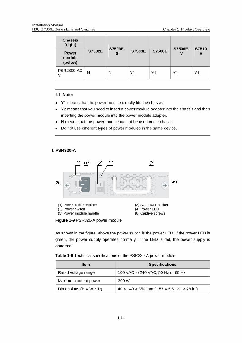
I. PSR320-A
(1) Power cable retainer (2) AC power socket (3) Power switch (4) Power LED (5) Power module handle (6) Captive screws
Figure 1-9 PSR320-A power module
As shown in the figure, above the power switch is the power LED. If the power LED is green, the power supply operates normally. If the LED is red, the power supply is abnormal.
Table 1-6 Technical specifications of the PSR320-A power module
Item Specifications
Rated voltage range 100 VAC to 240 VAC; 50 Hz or 60 Hz
Maximum output power 300 W
Dimensions (H × W × D) 40 × 140 × 350 mm (1.57 × 5.51 × 13.78 in.)
Installation Manual H3C S7500E Series Ethernet Switches Chapter 1 Product Overview
1-12
Note:
The PSR320-A uses a 10-A AC power cable.
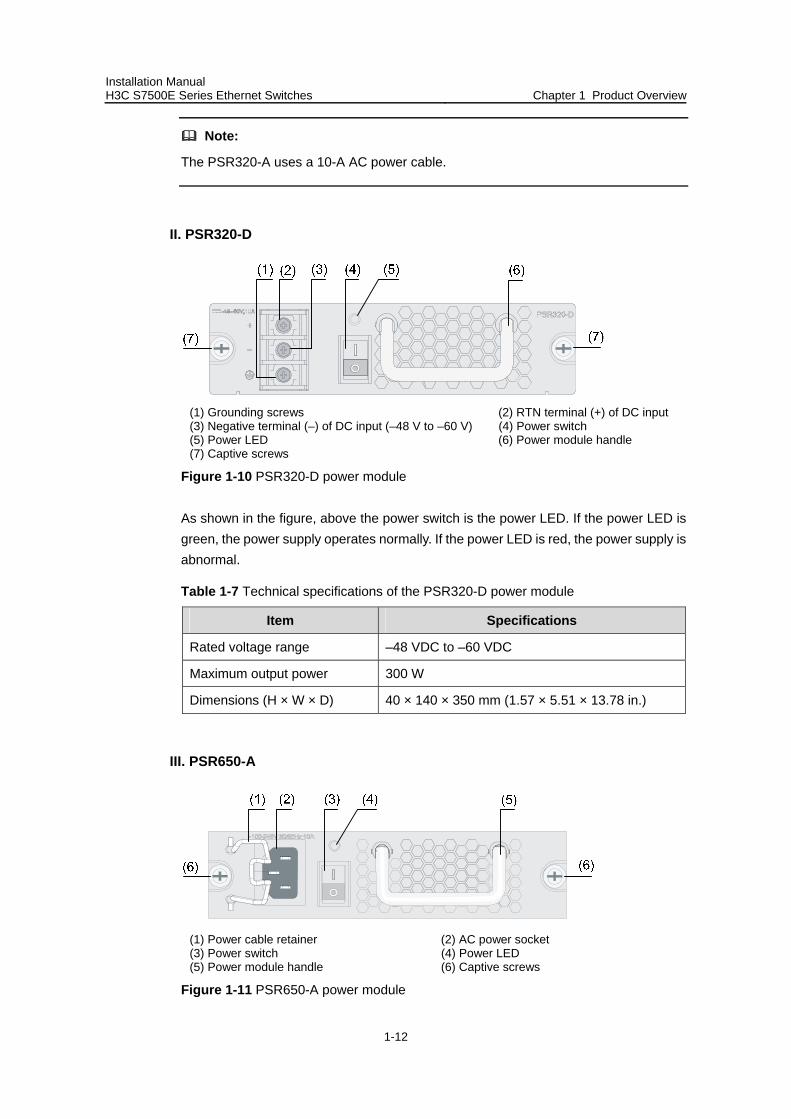
II. PSR320-D
(1) Grounding screws (2) RTN terminal (+) of DC input (3) Negative terminal (–) of DC input (–48 V to –60 V) (4) Power switch (5) Power LED (6) Power module handle (7) Captive screws
Figure 1-10 PSR320-D power module
As shown in the figure, above the power switch is the power LED. If the power LED is green, the power supply operates normally. If the power LED is red, the power supply is abnormal.
Table 1-7 Technical specifications of the PSR320-D power module
Item Specifications
Rated voltage range –48 VDC to –60 VDC
Maximum output power 300 W
Dimensions (H × W × D) 40 × 140 × 350 mm (1.57 × 5.51 × 13.78 in.)
III. PSR650-A
(1) Power cable retainer (2) AC power socket (3) Power switch (4) Power LED (5) Power module handle (6) Captive screws
Figure 1-11 PSR650-A power module

Installation Manual H3C S7500E Series Ethernet Switches Chapter 1 Product Overview
1-13
Above the power switch is the power LED. If the power LED is green, the power supply operates normally. If the LED is red, the power supply is abnormal.
Table 1-8 Technical specifications of the PSR650-A power module
Item Specifications
Rated voltage range 100 VAC to 240 VAC; 50 Hz or 60 Hz
Maximum output power 650 W
Dimensions (H × W × D) 40 × 140 × 350 mm (1.57 × 5.51 × 13.78 in.)
Note:
The PSR650-A uses a 10 A AC power cable.
IV. PSR650-D
(1) Grounding screw (2) RTN terminal (+) of DC input (3) Negative terminal (–) of DC input (–48 V to –60 V) (4) Power switch (5) Power LED (6) Power module handle (7) Captive screws
Figure 1-12 PSR650-D power module
Above the power switch is the power LED. If the power LED is green, the power supply operates normally. If the power LED is red, the power supply is abnormal.
Table 1-9 Technical specifications of the PSR650-D power module
Item Specifications
Rated voltage range –48 VDC to –60 VDC
Maximum output power 650 W
Dimensions (H × W × D) 40 × 140 × 350 mm (1.57 × 5.51 × 13.78 in.)
Installation Manual H3C S7500E Series Ethernet Switches Chapter 1 Product Overview
1-14
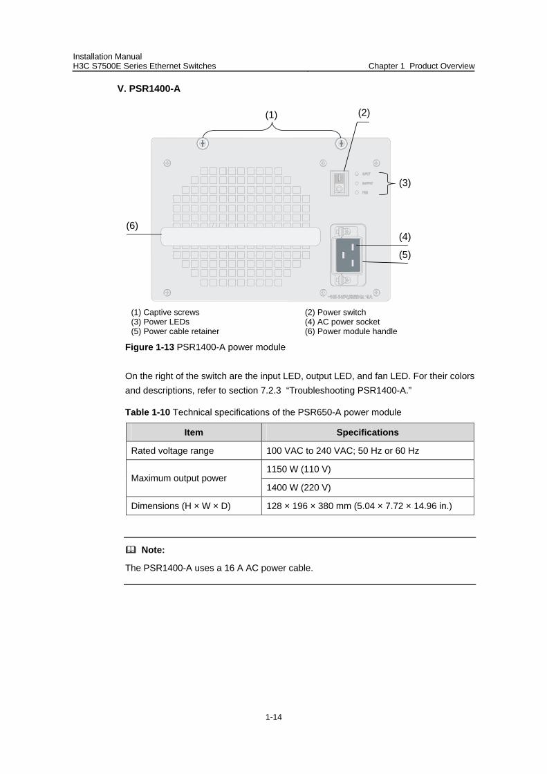
V. PSR1400-A
(2)
(6)(4)
(5)
(3)
(1)
(1) Captive screws (2) Power switch (3) Power LEDs (4) AC power socket (5) Power cable retainer (6) Power module handle
Figure 1-13 PSR1400-A power module
On the right of the switch are the input LED, output LED, and fan LED. For their colors and descriptions, refer to section 7.2.3 “Troubleshooting PSR1400-A.”
Table 1-10 Technical specifications of the PSR650-A power module
Item Specifications
Rated voltage range 100 VAC to 240 VAC; 50 Hz or 60 Hz
1150 W (110 V) Maximum output power
1400 W (220 V)
Dimensions (H × W × D) 128 × 196 × 380 mm (5.04 × 7.72 × 14.96 in.)
Note:
The PSR1400-A uses a 16 A AC power cable.
Installation Manual H3C S7500E Series Ethernet Switches Chapter 1 Product Overview
1-15
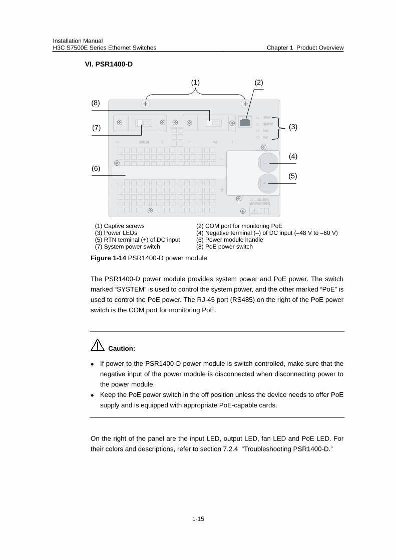
VI. PSR1400-D
(8)
(6)
(4)
(5)
(3)(7)
(2)(1)
(1) Captive screws (2) COM port for monitoring PoE (3) Power LEDs (4) Negative terminal (–) of DC input (–48 V to –60 V)(5) RTN terminal (+) of DC input (6) Power module handle (7) System power switch (8) PoE power switch
Figure 1-14 PSR1400-D power module
The PSR1400-D power module provides system power and PoE power. The switch marked “SYSTEM” is used to control the system power, and the other marked “PoE” is used to control the PoE power. The RJ-45 port (RS485) on the right of the PoE power switch is the COM port for monitoring PoE.
Caution:
If power to the PSR1400-D power module is switch controlled, make sure that the negative input of the power module is disconnected when disconnecting power to the power module.
Keep the PoE power switch in the off position unless the device needs to offer PoE supply and is equipped with appropriate PoE-capable cards.
On the right of the panel are the input LED, output LED, fan LED and PoE LED. For their colors and descriptions, refer to section 7.2.4 “Troubleshooting PSR1400-D.”
Installation Manual H3C S7500E Series Ethernet Switches Chapter 1 Product Overview
1-16
Table 1-11 Technical specifications of the PSR1400-D DC power module
Item Specifications
Rated voltage range –48 VDC to –60 VDC
Maximum system output power 1400 W
Maximum PoE output power 6720 W
Dimensions (H × W × D) 128 × 196 × 380 mm (5.04 × 7.72 × 14.96 in.)
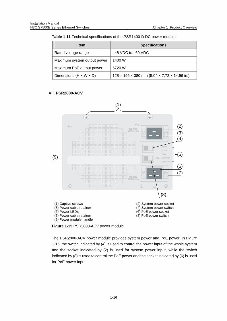
VII. PSR2800-ACV
(1)
(2)(3)
(6)(7)
(4)
(5)
(8)
(9)
(1) Captive screws (2) System power socket (3) Power cable retainer (4) System power switch (5) Power LEDs (6) PoE power socket (7) Power cable retainer (8) PoE power switch (9) Power module handle
Figure 1-15 PSR2800-ACV power module
The PSR2800-ACV power module provides system power and PoE power. In Figure 1-15, the switch indicated by (4) is used to control the power input of the whole system and the socket indicated by (2) is used for system power input, while the switch indicated by (8) is used to control the PoE power and the socket indicated by (6) is used for PoE power input.
Installation Manual H3C S7500E Series Ethernet Switches Chapter 1 Product Overview
1-17
Caution:
Keep the PoE power switch in the off position unless the device needs to offer PoE supply and is equipped with appropriate PoE-capable cards.
On the right of the panel are the input LED, output LED, fan LED, PoE input LED, and PoE output LED. For the descriptions of these LEDs, refer to section 7.2.5 “Troubleshooting PSR2800-ACV.”
Table 1-12 Technical specifications of the PSR2800-ACV power module
Specifications Value or range
Rated voltage range 100 VAC to 240 VAC, 50 Hz or 60 Hz
1150 W (110 V) Maximum system output power
1400 W (220 V)
1150 W (110 V) Maximum PoE output power
1400 W (220 V)
Physical dimensions (H × W × D) 128 × 196 × 380 mm (5.04 × 7.72 × 14.96 in.)
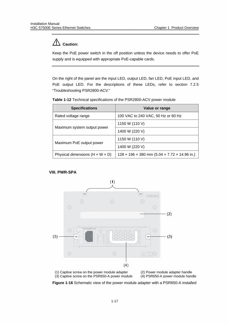
VIII. PWR-SPA
(1) Captive screw on the power module adapter (2) Power module adapter handle (3) Captive screw on the PSR650-A power module (4) PSR650-A power module handle
Figure 1-16 Schematic view of the power module adapter with a PSR650-A installed
Installation Manual H3C S7500E Series Ethernet Switches Chapter 1 Product Overview
1-18
When the system power consumption of a switch (S7503E, S7506E, S7506E-V, or S7510E) is less than the maximum output power of a 1U power module, you can first insert the PWR-SPA power module adapters into the switch, and then insert 1U power modules into the power module adapters. By doing so, you can use the 1U-high power modules to power the switch.
A PWR-SPA power module adapter has the same physical dimensions with a 3U power module.
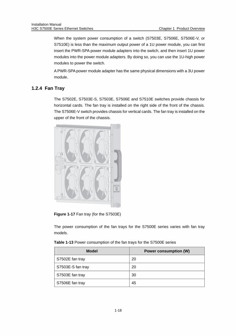
1.2.4 Fan Tray
The S7502E, S7503E-S, S7503E, S7506E and S7510E switches provide chassis for horizontal cards. The fan tray is installed on the right side of the front of the chassis. The S7506E-V switch provides chassis for vertical cards. The fan tray is installed on the upper of the front of the chassis.
Figure 1-17 Fan tray (for the S7503E)
The power consumption of the fan trays for the S7500E series varies with fan tray models.
Table 1-13 Power consumption of the fan trays for the S7500E series
Model Power consumption (W)
S7502E fan tray 20
S7503E-S fan tray 20
S7503E fan tray 30
S7506E fan tray 45
Installation Manual H3C S7500E Series Ethernet Switches Chapter 1 Product Overview
1-19
Model Power consumption (W)
S7510E fan tray 50
S7506E-V fan tray 50
1.2.5 Air Filter
Over a long period of time, dust may block the air filter at the air intake vent of the S7500E series. As a result, the heat dissipation of the system may be affected. You are recommended to clean the air filter every three months. Air filters are optional accessories.
Since the air flows up from the bottom, air filters for the S7506E-V, different from those for the other models, are installed on the front and rear sides near the bottom of the chassis.
1.3 SRPUs
1.3.1 SRPU Types
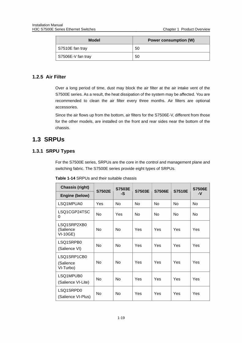
For the S7500E series, SRPUs are the core in the control and management plane and switching fabric. The S7500E series provide eight types of SRPUs.
Table 1-14 SRPUs and their suitable chassis
Chassis (right)
Engine (below) S7502E S7503E
-S S7503E S7506E S7510E S7506E-V
LSQ1MPUA0 Yes No No No No No
LSQ1CGP24TSC0 No Yes No No No No
LSQ1SRP2XB0 (Salience VI-10GE)
No No Yes Yes Yes Yes
LSQ1SRPB0 (Salience VI)
No No Yes Yes Yes Yes
LSQ1SRP1CB0 (Salience VI-Turbo)
No No Yes Yes Yes Yes
LSQ1MPUB0 (Salience VI-Lite)
No No Yes Yes Yes Yes
LSQ1SRPD0 (Salience VI-Plus)
No No Yes Yes Yes Yes
Installation Manual H3C S7500E Series Ethernet Switches Chapter 1 Product Overview
1-20
Chassis (right)
Engine (below) S7502E S7503E
-S S7503E S7506E S7510E S7506E-V
LSQ1SRP12GB0 (Salience VI-GE)
No No Yes Yes Yes Yes
Note:
The S7500E series, except the S7503E-S, are a dual-SRPU system. The SRPUs in a chassis must be of the same type.
1.3.2 LSQ1MPUA0 SRPU
I. Applicable model
S7502E
II. Technical specifications
Table 1-15 Technical specifications of the LSQ1MPUA0
Item Specifications
CPU MIPS64, 600 MHz
Boot ROM 512 KB
Flash memory 64 MB
DDR SDRAM 512 MB
Dimensions (H × W × D) 45 × 199 × 355 mm (1.77 × 7.83 × 13.98 in.)
Interfaces
One compact flash (CF) card interface One console port, used for local or remote
configuration and management of the switch through a dialup configuration
One 10/100Base-TX management Ethernet port
Power consumption 10 W to 15 W
Note:
The dimensions of the S7500E series are expressed in the form of H × W × D, where H: Height of the front panel of the card. W: Width of the part inserted into the chassis, instead of that of the front panel. D: Depth from the front panel to the other end, excluding the length of the handle.
Installation Manual H3C S7500E Series Ethernet Switches Chapter 1 Product Overview
1-21
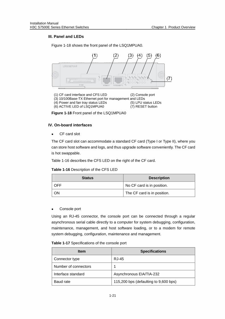
III. Panel and LEDs
Figure 1-18 shows the front panel of the LSQ1MPUA0.
(1) CF card interface and CFS LED (2) Console port (3) 10/100Base-TX Ethernet port for management and LEDs (4) Power and fan tray status LEDs (5) LPU status LEDs (6) ACTIVE LED of LSQ1MPUA0 (7) RESET button
Figure 1-18 Front panel of the LSQ1MPUA0
IV. On-board interfaces
CF card slot
The CF card slot can accommodate a standard CF card (Type I or Type II), where you can store host software and logs, and thus upgrade software conveniently. The CF card is hot swappable.
Table 1-16 describes the CFS LED on the right of the CF card.
Table 1-16 Description of the CFS LED
Status Description
OFF No CF card is in position.
ON The CF card is in position.
Console port
Using an RJ-45 connector, the console port can be connected through a regular asynchronous serial cable directly to a computer for system debugging, configuration, maintenance, management, and host software loading, or to a modem for remote system debugging, configuration, maintenance and management.
Table 1-17 Specifications of the console port
Item Specifications
Connector type RJ-45
Number of connectors 1
Interface standard Asynchronous EIA/TIA-232
Baud rate 115,200 bps (defaulting to 9,600 bps)
Installation Manual H3C S7500E Series Ethernet Switches Chapter 1 Product Overview
1-22
Item Specifications
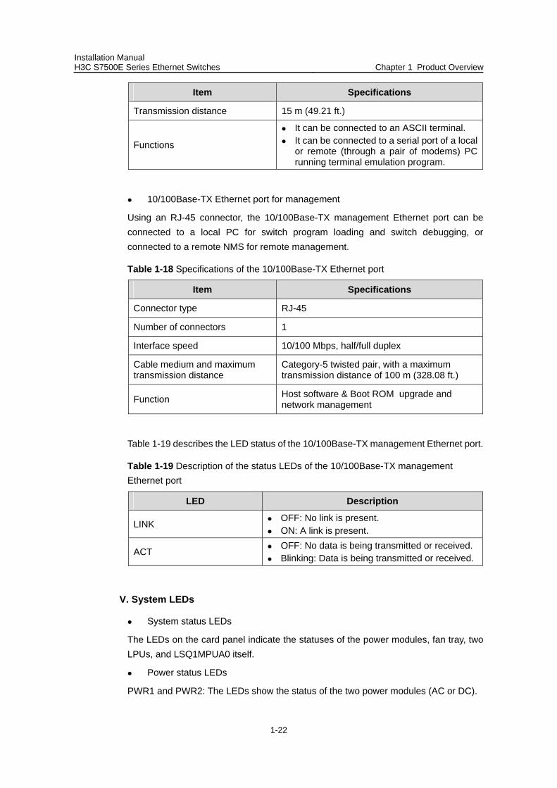
Transmission distance 15 m (49.21 ft.)
Functions
It can be connected to an ASCII terminal. It can be connected to a serial port of a local
or remote (through a pair of modems) PC running terminal emulation program.
10/100Base-TX Ethernet port for management
Using an RJ-45 connector, the 10/100Base-TX management Ethernet port can be connected to a local PC for switch program loading and switch debugging, or connected to a remote NMS for remote management.
Table 1-18 Specifications of the 10/100Base-TX Ethernet port
Item Specifications
Connector type RJ-45
Number of connectors 1
Interface speed 10/100 Mbps, half/full duplex
Cable medium and maximum transmission distance
Category-5 twisted pair, with a maximum transmission distance of 100 m (328.08 ft.)
Function Host software & Boot ROM upgrade and network management
Table 1-19 describes the LED status of the 10/100Base-TX management Ethernet port.
Table 1-19 Description of the status LEDs of the 10/100Base-TX management Ethernet port
LED Description
LINK OFF: No link is present. ON: A link is present.
ACT OFF: No data is being transmitted or received. Blinking: Data is being transmitted or received.
V. System LEDs
System status LEDs
The LEDs on the card panel indicate the statuses of the power modules, fan tray, two LPUs, and LSQ1MPUA0 itself.
Power status LEDs
PWR1 and PWR2: The LEDs show the status of the two power modules (AC or DC).
Installation Manual H3C S7500E Series Ethernet Switches Chapter 1 Product Overview
1-23
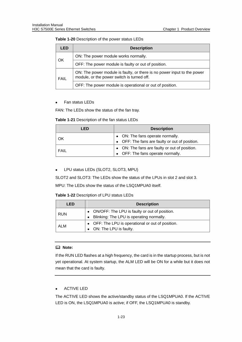
Table 1-20 Description of the power status LEDs
LED Description
ON: The power module works normally. OK
OFF: The power module is faulty or out of position.
ON: The power module is faulty, or there is no power input to the power module, or the power switch is turned off. FAIL OFF: The power module is operational or out of position.
Fan status LEDs
FAN: The LEDs show the status of the fan tray.
Table 1-21 Description of the fan status LEDs
LED Description
OK ON: The fans operate normally. OFF: The fans are faulty or out of position.
FAIL ON: The fans are faulty or out of position. OFF: The fans operate normally.
LPU status LEDs (SLOT2, SLOT3, MPU)
SLOT2 and SLOT3: The LEDs show the status of the LPUs in slot 2 and slot 3.
MPU: The LEDs show the status of the LSQ1MPUA0 itself.
Table 1-22 Description of LPU status LEDs
LED Description
RUN ON/OFF: The LPU is faulty or out of position. Blinking: The LPU is operating normally.
ALM OFF: The LPU is operational or out of position. ON: The LPU is faulty.
Note:
If the RUN LED flashes at a high frequency, the card is in the startup process, but is not yet operational. At system startup, the ALM LED will be ON for a while but it does not mean that the card is faulty.
ACTIVE LED
The ACTIVE LED shows the active/standby status of the LSQ1MPUA0. If the ACTIVE LED is ON, the LSQ1MPUA0 is active; if OFF, the LSQ1MPUA0 is standby.
Installation Manual H3C S7500E Series Ethernet Switches Chapter 1 Product Overview
1-24
VI. RESET button
A reset button is provided on the LSQ1MPUA0 for you to reset the card when necessary.
1.3.3 Dedicated S7503E-S SRPU-LSQ1CGP24TSC0
I. Applicable model
S7503E-S
II. Technical specifications
Table 1-23 Technical specifications of the LSQ1CGP24TSC0
Item Specifications
CPU MIPS64, 400 MHz
Boot ROM 512 KB
Flash memory 64 MB
DDR SDRAM 512 MB
Dimensions (H × W × D) 45 × 377 × 355 mm (1.77 × 14.84 × 13.98 in.)
Ports
Twenty-four 1000Base-X-SFP/100Base-FX-SFP ports, eight of which can form eight Combo ports with the eight 10/100/1000Base-T GE ports
One console port, used for local or remote configuration and management of the switch through a dialup connection
One 10/100Base-TX port for management and upgrade
Power consumption 25 W to 45 W
III. Panel and LEDs
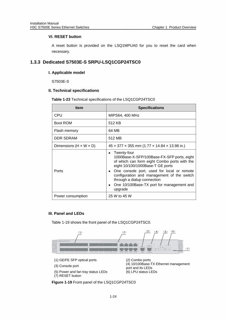
Table 1-19 shows the front panel of the LSQ1CGP24TSC0.
(1) (2) (3) (4) (5) (6)
(7)
(1) GE/FE SFP optical ports (2) Combo ports
(3) Console port (4) 10/100Base-TX Ethernet management port and its LEDs
(5) Power and fan tray status LEDs (6) LPU status LEDs (7) RESET button
Figure 1-19 Front panel of the LSQ1CGP24TSC0
Installation Manual H3C S7500E Series Ethernet Switches Chapter 1 Product Overview
1-25
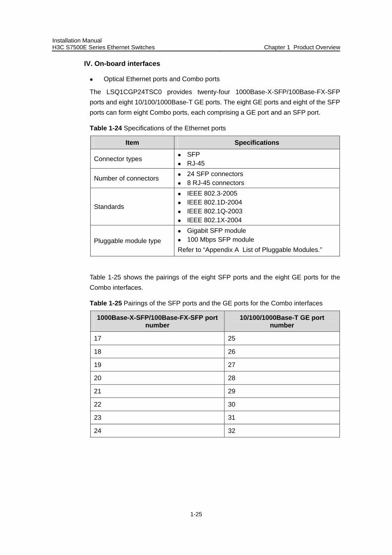
IV. On-board interfaces
Optical Ethernet ports and Combo ports
The LSQ1CGP24TSC0 provides twenty-four 1000Base-X-SFP/100Base-FX-SFP ports and eight 10/100/1000Base-T GE ports. The eight GE ports and eight of the SFP ports can form eight Combo ports, each comprising a GE port and an SFP port.
Table 1-24 Specifications of the Ethernet ports
Item Specifications
Connector types SFP RJ-45
Number of connectors 24 SFP connectors 8 RJ-45 connectors
Standards
IEEE 802.3-2005 IEEE 802.1D-2004 IEEE 802.1Q-2003 IEEE 802.1X-2004
Pluggable module type Gigabit SFP module 100 Mbps SFP module
Refer to “Appendix A List of Pluggable Modules.”
Table 1-25 shows the pairings of the eight SFP ports and the eight GE ports for the Combo interfaces.
Table 1-25 Pairings of the SFP ports and the GE ports for the Combo interfaces
1000Base-X-SFP/100Base-FX-SFP port number
10/100/1000Base-T GE port number
17 25
18 26
19 27
20 28
21 29
22 30
23 31
24 32
Installation Manual H3C S7500E Series Ethernet Switches Chapter 1 Product Overview
1-26
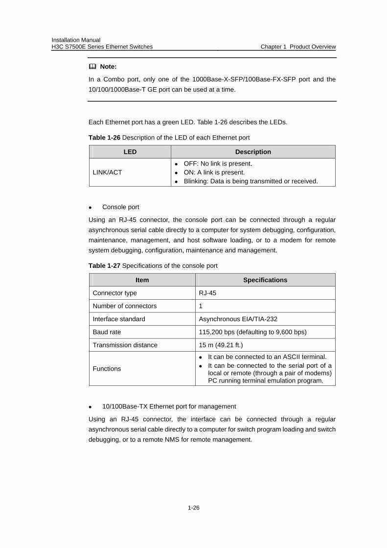
Note:
In a Combo port, only one of the 1000Base-X-SFP/100Base-FX-SFP port and the 10/100/1000Base-T GE port can be used at a time.
Each Ethernet port has a green LED. Table 1-26 describes the LEDs.
Table 1-26 Description of the LED of each Ethernet port
LED Description
LINK/ACT OFF: No link is present. ON: A link is present. Blinking: Data is being transmitted or received.
Console port
Using an RJ-45 connector, the console port can be connected through a regular asynchronous serial cable directly to a computer for system debugging, configuration, maintenance, management, and host software loading, or to a modem for remote system debugging, configuration, maintenance and management.
Table 1-27 Specifications of the console port
Item Specifications
Connector type RJ-45
Number of connectors 1
Interface standard Asynchronous EIA/TIA-232
Baud rate 115,200 bps (defaulting to 9,600 bps)
Transmission distance 15 m (49.21 ft.)
Functions
It can be connected to an ASCII terminal. It can be connected to the serial port of a
local or remote (through a pair of modems) PC running terminal emulation program.
10/100Base-TX Ethernet port for management
Using an RJ-45 connector, the interface can be connected through a regular asynchronous serial cable directly to a computer for switch program loading and switch debugging, or to a remote NMS for remote management.
Installation Manual H3C S7500E Series Ethernet Switches Chapter 1 Product Overview
1-27
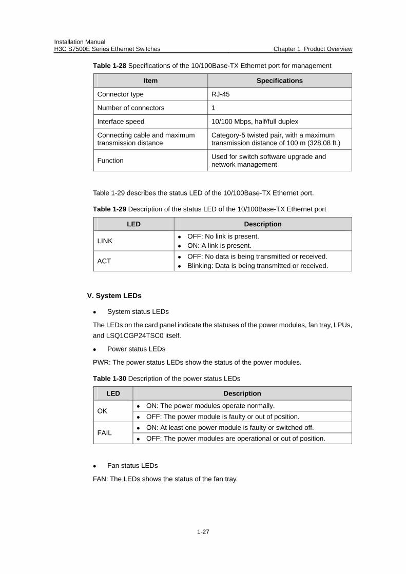
Table 1-28 Specifications of the 10/100Base-TX Ethernet port for management
Item Specifications
Connector type RJ-45
Number of connectors 1
Interface speed 10/100 Mbps, half/full duplex
Connecting cable and maximum transmission distance
Category-5 twisted pair, with a maximum transmission distance of 100 m (328.08 ft.)
Function Used for switch software upgrade and network management
Table 1-29 describes the status LED of the 10/100Base-TX Ethernet port.
Table 1-29 Description of the status LED of the 10/100Base-TX Ethernet port
LED Description
LINK OFF: No link is present. ON: A link is present.
ACT OFF: No data is being transmitted or received. Blinking: Data is being transmitted or received.
V. System LEDs
System status LEDs
The LEDs on the card panel indicate the statuses of the power modules, fan tray, LPUs, and LSQ1CGP24TSC0 itself.
Power status LEDs
PWR: The power status LEDs show the status of the power modules.
Table 1-30 Description of the power status LEDs
LED Description
ON: The power modules operate normally. OK
OFF: The power module is faulty or out of position. ON: At least one power module is faulty or switched off.
FAIL OFF: The power modules are operational or out of position.
Fan status LEDs
FAN: The LEDs shows the status of the fan tray.
Installation Manual H3C S7500E Series Ethernet Switches Chapter 1 Product Overview
1-28
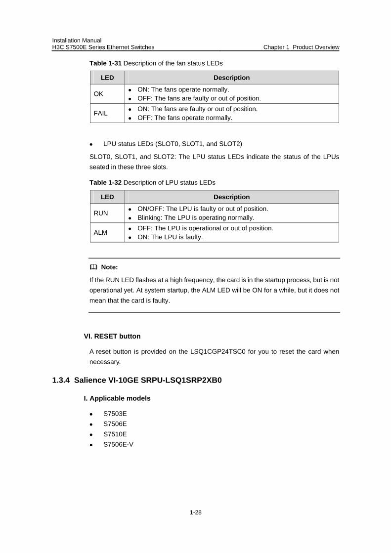
Table 1-31 Description of the fan status LEDs
LED Description
OK ON: The fans operate normally. OFF: The fans are faulty or out of position.
FAIL ON: The fans are faulty or out of position. OFF: The fans operate normally.
LPU status LEDs (SLOT0, SLOT1, and SLOT2)
SLOT0, SLOT1, and SLOT2: The LPU status LEDs indicate the status of the LPUs seated in these three slots.
Table 1-32 Description of LPU status LEDs
LED Description
RUN ON/OFF: The LPU is faulty or out of position. Blinking: The LPU is operating normally.
ALM OFF: The LPU is operational or out of position. ON: The LPU is faulty.
Note:
If the RUN LED flashes at a high frequency, the card is in the startup process, but is not operational yet. At system startup, the ALM LED will be ON for a while, but it does not mean that the card is faulty.
VI. RESET button
A reset button is provided on the LSQ1CGP24TSC0 for you to reset the card when necessary.
1.3.4 Salience VI-10GE SRPU-LSQ1SRP2XB0
I. Applicable models
S7503E S7506E S7510E S7506E-V

Installation Manual H3C S7500E Series Ethernet Switches Chapter 1 Product Overview
1-29
II. Technical specifications
Table 1-33 Technical specifications of the LSQ1SRP2XB0
Item Specifications
CPU MIPS64, 600 MHz
Boot ROM 512 KB
Flash memory 64 MB
DDR SDRAM 512 MB
Dimensions (H × W × D) 45 × 377 × 355 mm (1.77 × 14.84 × 13.98 in.)
Interfaces
One CF card interface Two 10GBase-R-XFP Ethernet ports One console port, used for local or remote
configuration and management of the switch through a dialup connection
One 10/100Base-TX management Ethernet port
Power consumption 55 W to 65 W
III. Panel and LEDs
Figure 1-20 shows the front panel of the LSQ1SRP2XB0.
(1) CF card slot and CFS LED (2) 10GBase-R-XFP Ethernet ports and LEDs (3) Console port (4) 10/100Base-TX Ethernet port for management and LEDs (5) Power and fan tray status LEDs (6) LPU status LEDs (7) ACTIVE LED of LSQ1SRP2XB0 (8) RESET button
Figure 1-20 Front panel of the LSQ1SRP2XB0
IV. On-board interfaces
CF card slot
The CF card slot can accommodate a standard CF card (Type I or Type II), where you can store host software and logs, and thus upgrade software conveniently. The CF card is hot swappable.
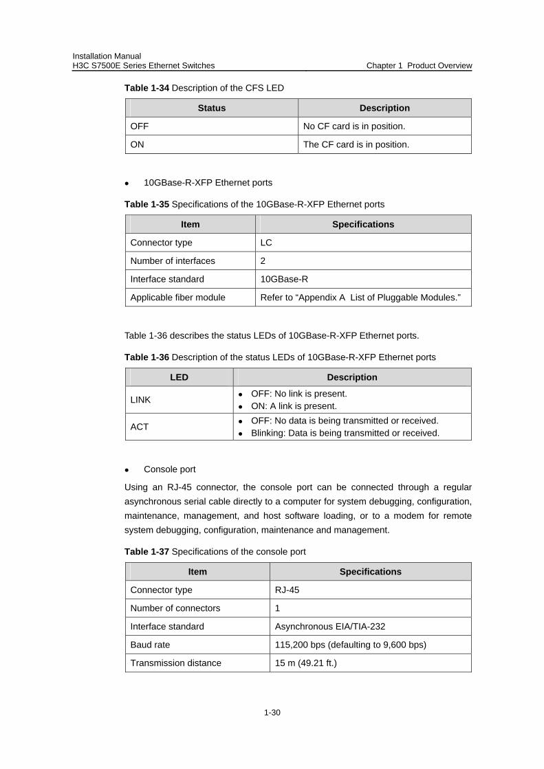
Table 1-34 describes the CFS LED on the right of the CF card.
Installation Manual H3C S7500E Series Ethernet Switches Chapter 1 Product Overview
1-30
Table 1-34 Description of the CFS LED
Status Description
OFF No CF card is in position.
ON The CF card is in position.
10GBase-R-XFP Ethernet ports
Table 1-35 Specifications of the 10GBase-R-XFP Ethernet ports
Item Specifications
Connector type LC
Number of interfaces 2
Interface standard 10GBase-R
Applicable fiber module Refer to “Appendix A List of Pluggable Modules.”
Table 1-36 describes the status LEDs of 10GBase-R-XFP Ethernet ports.
Table 1-36 Description of the status LEDs of 10GBase-R-XFP Ethernet ports
LED Description
LINK OFF: No link is present. ON: A link is present.
ACT OFF: No data is being transmitted or received. Blinking: Data is being transmitted or received.
Console port
Using an RJ-45 connector, the console port can be connected through a regular asynchronous serial cable directly to a computer for system debugging, configuration, maintenance, management, and host software loading, or to a modem for remote system debugging, configuration, maintenance and management.
Table 1-37 Specifications of the console port
Item Specifications
Connector type RJ-45
Number of connectors 1
Interface standard Asynchronous EIA/TIA-232
Baud rate 115,200 bps (defaulting to 9,600 bps)
Transmission distance 15 m (49.21 ft.)

Installation Manual H3C S7500E Series Ethernet Switches Chapter 1 Product Overview
1-31
Item Specifications
Functions
It can be connected to an ASCII terminal. It can be connected to a serial port of a local
or remote (through a pair of modems) PC running terminal emulation program.
10/100Base-TX management Ethernet port
Using an RJ-45 connector, the 10/100Base-TX management Ethernet port can be connected to a local PC for switch program loading and switch debugging, or connected to a remote NMS for remote management.
Table 1-38 Specifications of the 10/100Base-TX Ethernet port for management
Item Specifications
Connector type RJ-45
Number of interfaces 1
Interface speed 10/100 Mbps, half/full duplex
Cable medium and maximum transmission distance
Category-5 twisted pair, with a maximum transmission distance of 100 m (328.08 ft.)
Function Used for switch software upgrade and network management
Table 1-39 Description of the status LEDs of the 10/100Base-TX management Ethernet port
LED Description
LINK OFF: No link is present. ON: A link is present.
ACT OFF: No data is being transmitted or received. Blinking: Data is being transmitted or received.
V. System LEDs
System status LEDs
The LEDs on the card panel indicate the statuses of the power modules, fan tray, twelve LPUs, and LSQ1SRP2XB0 itself.
Power status LEDs
PWR: The power status LEDs show the status of the power modules.
Installation Manual H3C S7500E Series Ethernet Switches Chapter 1 Product Overview
1-32
Table 1-40 Description of the power status LEDs
LED Description
ON: The power modules operate normally. OK
OFF: The power module is faulty or out of position.
ON: At least one power module is faulty or switched off. FAIL
OFF: The power modules are operational or out of position.
Fan status LEDs
FAN: The LEDs show the status of the fan tray.
Table 1-41 Description of the fan status LEDs
LED Description
OK ON: The fans operate normally. OFF: The fans are faulty or out of position.
FAIL ON: The fans are faulty or out of position. OFF: The fans operate normally.
LPU status LEDs (SLOT0 through SLOT11)
SLOT0 through SLOT11: The LPU status LEDs indicate the status of the LPUs seated in the 12 slots.
Table 1-42 Description of LPU status LEDs
LED Description
RUN ON/OFF: The LPU is faulty or out of position. Blinking: The LPU is operating normally.
ALM OFF: The LPU is operational or out of position. ON: The LPU is faulty.
Note:
If the RUN LED flashes at a high frequency, the card is in the startup process, but is not yet operational. At system startup, the ALM LED will be ON for a while, but it does not mean that the card is faulty
ACTIVE LED
The ACTIVE LED shows the active/standby status of the LSQ1SRP2XB0. If the ACTIVE LED is ON, the LSQ1SRP2XB0 is active; if OFF, the LSQ1SRP2XB0 is standby.
Installation Manual H3C S7500E Series Ethernet Switches Chapter 1 Product Overview
1-33
VI. RESET button
A reset button is provided on the LSQ1SRP2XB0 for you to reset the card when necessary.
1.3.5 Salience VI SRPU-LSQ1SRPB0
I. Applicable models
S7503E S7506E S7510E S7506E-V
II. Technical specifications
Table 1-43 Technical specifications of the LSQ1SRPB0
Item Specifications
CPU MIPS64, 600 MHz
Boot ROM 512 KB
Flash memory 64 MB
DDR SDRAM 512 MB
Dimensions (H x W x D) 45 × 377 × 355 mm (1.77 × 14.84 × 13.98 in.)
Ports
One CF card slot One console port, used for local or remote
configuration and management of the switch through a dialup connection
One 10/100Base-TX management Ethernet port
Power consumption 42 W to 50 W
III. Panel and LEDs
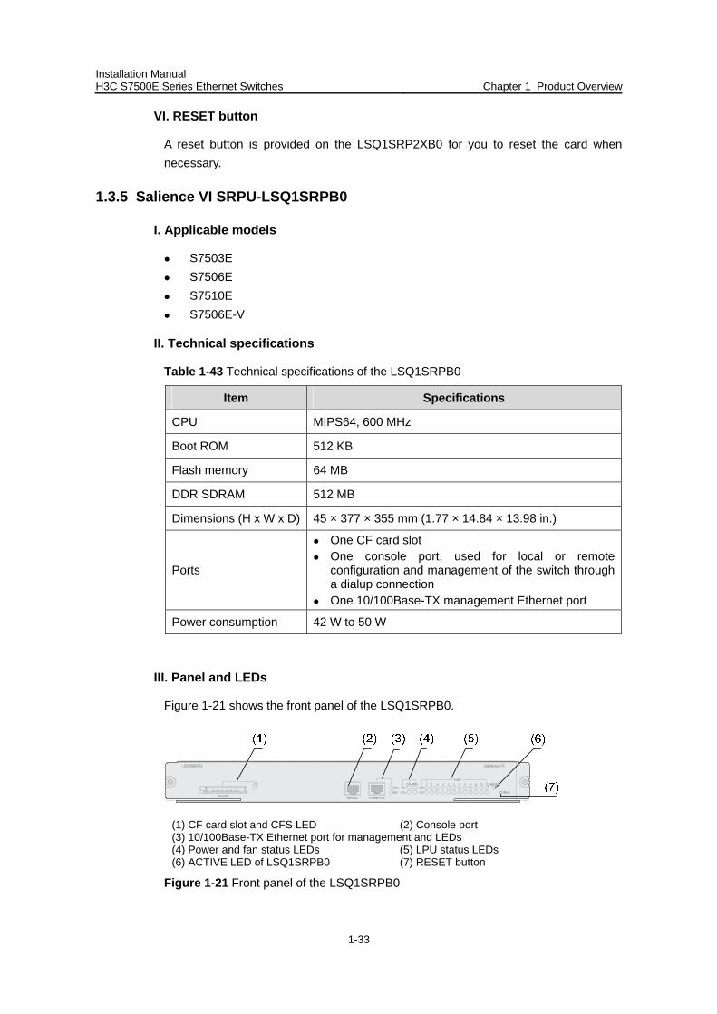
Figure 1-21 shows the front panel of the LSQ1SRPB0.
(1) CF card slot and CFS LED (2) Console port (3) 10/100Base-TX Ethernet port for management and LEDs (4) Power and fan status LEDs (5) LPU status LEDs (6) ACTIVE LED of LSQ1SRPB0 (7) RESET button
Figure 1-21 Front panel of the LSQ1SRPB0
Installation Manual H3C S7500E Series Ethernet Switches Chapter 1 Product Overview
1-34
IV. On-board interfaces
CF card slot
The CF card slot can accommodate a standard CF card (Type I or Type II), where you can store host software and logs, and thus upgrade software conveniently. The CF card is hot swappable.
Table 1-44 describes the CFS LED on the right of the CF card.
Table 1-44 Description of the CFS LED
Status Description
OFF No CF card is in position.
ON The CF card is in position.
Console port
Using an RJ-45 connector, the console port can be connected through a regular asynchronous serial cable directly to a computer for system debugging, configuration, maintenance, management, and host software loading, or to a modem for remote system debugging, configuration, maintenance and management.
Table 1-45 Specifications of the console port
Item Specifications
Connector type RJ-45
Number of connectors 1
Interface standard Asynchronous EIA/TIA-232
Baud rate 115,200 bps (defaulting to 9,600 bps)
Transmission distance 15 m (49.21 ft.)
Functions
It can be connected to an ASCII terminal. It can be connected to the serial port of a
local or remote (through a pair of modems) PC running terminal emulation program.
10/100BasE-TX management Ethernet port
Using an RJ-45 connector, the 10/100Base-TX management Ethernet port can be connected to a local PC for switch program loading and switch debugging, or connected to a remote NMS for remote management.
Installation Manual H3C S7500E Series Ethernet Switches Chapter 1 Product Overview
1-35
Table 1-46 Specifications of the 10/100Base-TX Ethernet port
Item Specifications
Connector type RJ-45
Number of interfaces 1
Interface speed 10/100 Mbps, half/full duplex
Connecting cable and maximum transmission distance
Category-5 twisted pair, with a maximum transmission distance of 100 m (328.08 ft.)
Function Used for switch software upgrade and network management
Table 1-47 describes the status LEDs of the 10/100Base-TX management Ethernet port.
Table 1-47 Description of the status LEDs of the 10/100Base-TX Ethernet port
LED Description
LINK OFF: No link is present. ON: A link is present.
ACT OFF: No data is being transmitted or received. Blinking: Data is being transmitted or received.
V. System LEDs
System status LED
The status LEDs on the panel indicate the statuses of the power modules, fan tray, twelve LPUs, and SQ1SRPB0 itself.
Power status LED
PWR: The power status LEDs show the status of the power modules
Table 1-48 Description of the power status LEDs
LED Description
ON: The power modules operate normally. OK
OFF: The power modules are faulty or out of position.
ON: At least one power module is faulty or switched off. FAIL
OFF: The power modules are operational or out of position.
Fan status LEDs
FAN: The LEDs show the status of the fan tray.
Installation Manual H3C S7500E Series Ethernet Switches Chapter 1 Product Overview
1-36
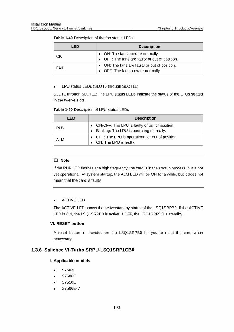
Table 1-49 Description of the fan status LEDs
LED Description
OK ON: The fans operate normally. OFF: The fans are faulty or out of position.
FAIL ON: The fans are faulty or out of position. OFF: The fans operate normally.
LPU status LEDs (SLOT0 through SLOT11)
SLOT1 through SLOT11: The LPU status LEDs indicate the status of the LPUs seated in the twelve slots.
Table 1-50 Description of LPU status LEDs
LED Description
RUN ON/OFF: The LPU is faulty or out of position. Blinking: The LPU is operating normally.
ALM OFF: The LPU is operational or out of position. ON: The LPU is faulty.
Note:
If the RUN LED flashes at a high frequency, the card is in the startup process, but is not yet operational. At system startup, the ALM LED will be ON for a while, but it does not mean that the card is faulty
ACTIVE LED
The ACTIVE LED shows the active/standby status of the LSQ1SRPB0. If the ACTIVE LED is ON, the LSQ1SRPB0 is active; if OFF, the LSQ1SRPB0 is standby.
VI. RESET button
A reset button is provided on the LSQ1SRPB0 for you to reset the card when necessary.
1.3.6 Salience VI-Turbo SRPU-LSQ1SRP1CB0
I. Applicable models
S7503E S7506E S7510E S7506E-V
Installation Manual H3C S7500E Series Ethernet Switches Chapter 1 Product Overview
1-37
II. Technical specifications
Table 1-51 Technical specifications of LSQ1SRP1CB0
Item Specifications
CPU MIPS64, 600 MHz
Boot ROM 512 KB
Flash memory 64 MB
DDR SDRAM 512 MB
Card physical dimensions (H x W x D) 45.1 × 377 × 355 mm (1.77 × 14.84 × 13.98 in.)
Interfaces
One CF card slot One console port, used for local or remote
configuration and management of the switch through a dialup connection
One 10/100Base-TX management Ethernet port
Power consumption 53 W to 60 W
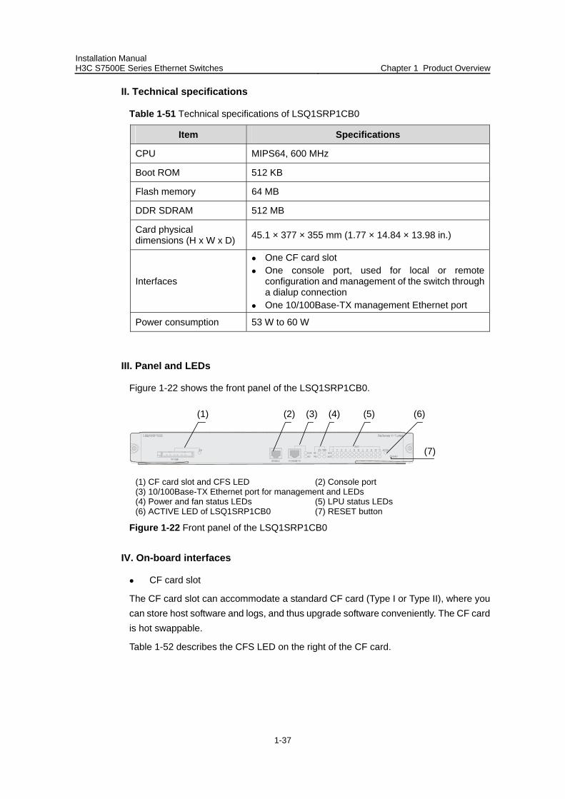
III. Panel and LEDs
Figure 1-22 shows the front panel of the LSQ1SRP1CB0.
(1) (2) (3) (4) (5)
(7)
(6)
(1) CF card slot and CFS LED (2) Console port (3) 10/100Base-TX Ethernet port for management and LEDs (4) Power and fan status LEDs (5) LPU status LEDs (6) ACTIVE LED of LSQ1SRP1CB0 (7) RESET button
Figure 1-22 Front panel of the LSQ1SRP1CB0
IV. On-board interfaces
CF card slot
The CF card slot can accommodate a standard CF card (Type I or Type II), where you can store host software and logs, and thus upgrade software conveniently. The CF card is hot swappable.
Table 1-52 describes the CFS LED on the right of the CF card.
Installation Manual H3C S7500E Series Ethernet Switches Chapter 1 Product Overview
1-38
Table 1-52 Description of the CFS LED
Status Description
OFF No CF card is in position.
ON The CF card is in position.
Console port
Using an RJ-45 connector, the console port can be connected through a regular asynchronous serial cable directly to a computer for system debugging, configuration, maintenance, management, and host software loading, or to a modem for remote system debugging, configuration, maintenance and management.
Table 1-53 Specifications of the console port
Item Specifications
Connector type RJ-45
Number of connectors 1
Interface standard Asynchronous EIA/TIA-232
Baud rate 115,200 bps (defaulting to 9,600 bps)
Transmission distance 15 m (49.21 ft.)
Functions
It can be connected to an ASCII terminal. It can be connected to a serial port of a
local or remote (through a pair of modems) PC running terminal emulation program.
10/100Base-TX management Ethernet port
Using an RJ-45 connector, the 10/100Base-TX management Ethernet port can be connected to a local PC for switch program loading and switch debugging, or connected to a remote NMS for remote management.
Table 1-54 Specifications of the 10/100Base-TX Ethernet port
Item Specifications
Connector type RJ-45
Number of interfaces 1
Interface speed 10/100 Mbps, half/full duplex
Cable medium and maximum transmission distance
Category-5 twisted pair, with a maximum transmission distance of 100 m (328.08 ft.)
Installation Manual H3C S7500E Series Ethernet Switches Chapter 1 Product Overview
1-39
Item Specifications
Function Used for switch software upgrade and network management
Table 1-55 describes the status LEDs of the 10/100Base-TX management Ethernet port.
Table 1-55 Description of the status LEDs of the 10/100Base-TX Ethernet port
LED Description
LINK OFF: No link is present. ON: A link is present.
ACT OFF: No data is being transmitted or received. Blinking: Data is being transmitted or received..
V. System LEDs
System status LEDs
The LEDs on the card panel indicate the statuses of the power modules, fans, LPUs seated in the twelve slots, and LSQ1SRP1CB0 itself.
Power status LEDs
PWR: The power status LEDs show the status of the power modules.
Table 1-56 Description of the power status LEDs
LED Description
ON: The power modules operate normally. OK
OFF: The power modules are faulty or out of position.
ON: At least one power module is faulty or out of position. FAIL
OFF: The power modules are operational or out of position.
Fan status LEDs
FAN: The LEDs show the status of the fan tray.
Installation Manual H3C S7500E Series Ethernet Switches Chapter 1 Product Overview
1-40
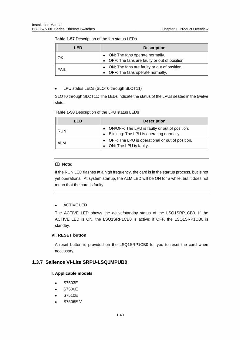
Table 1-57 Description of the fan status LEDs
LED Description
OK ON: The fans operate normally. OFF: The fans are faulty or out of position.
FAIL ON: The fans are faulty or out of position. OFF: The fans operate normally.
LPU status LEDs (SLOT0 through SLOT11)
SLOT0 through SLOT11: The LEDs indicate the status of the LPUs seated in the twelve slots.
Table 1-58 Description of the LPU status LEDs
LED Description
RUN ON/OFF: The LPU is faulty or out of position. Blinking: The LPU is operating normally.
ALM OFF: The LPU is operational or out of position. ON: The LPU is faulty.
Note:
If the RUN LED flashes at a high frequency, the card is in the startup process, but is not yet operational. At system startup, the ALM LED will be ON for a while, but it does not mean that the card is faulty
ACTIVE LED
The ACTIVE LED shows the active/standby status of the LSQ1SRP1CB0. If the ACTIVE LED is ON, the LSQ1SRP1CB0 is active; if OFF, the LSQ1SRP1CB0 is standby.
VI. RESET button
A reset button is provided on the LSQ1SRP1CB0 for you to reset the card when necessary.
1.3.7 Salience VI-Lite SRPU-LSQ1MPUB0
I. Applicable models
S7503E S7506E S7510E S7506E-V
Installation Manual H3C S7500E Series Ethernet Switches Chapter 1 Product Overview
1-41
II. Technial specifications
Table 1-59 Technical specifications of the LSQ1MPUB0
Item Specifications
CPU MIPS64, 600 MHz
Boot ROM 512 KB
Flash memory 64 MB
DDR SDRAM 512 MB
Dimensions (H x W x D) 45 × 377 × 355 mm (1.77 × 14.84 × 13.98 in.)
Interfaces
One CF card slot One console port, used for local or remote
configuration and management of the switch through a dialup connection
One 10/100Base-TX management Ethernet port
Power consumption 40 W to 45 W
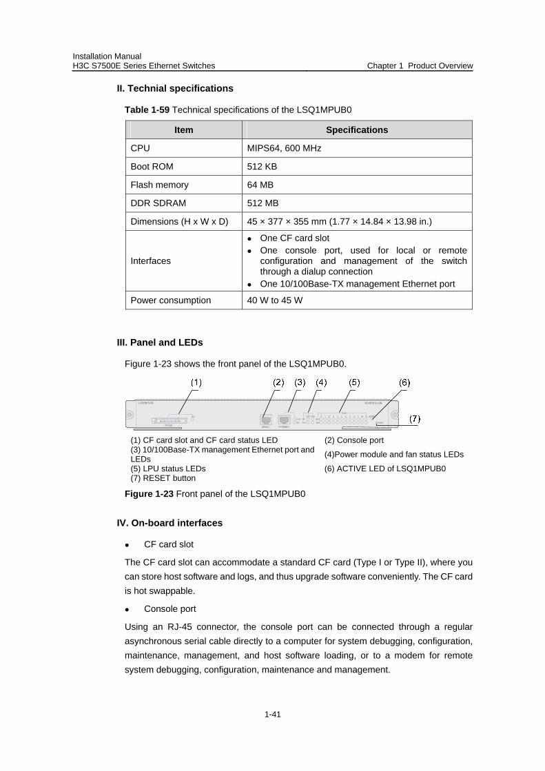
III. Panel and LEDs
Figure 1-23 shows the front panel of the LSQ1MPUB0.
(1) CF card slot and CF card status LED (2) Console port (3) 10/100Base-TX management Ethernet port and LEDs (4)Power module and fan status LEDs
(5) LPU status LEDs (6) ACTIVE LED of LSQ1MPUB0 (7) RESET button
Figure 1-23 Front panel of the LSQ1MPUB0
IV. On-board interfaces
CF card slot
The CF card slot can accommodate a standard CF card (Type I or Type II), where you can store host software and logs, and thus upgrade software conveniently. The CF card is hot swappable.
Console port
Using an RJ-45 connector, the console port can be connected through a regular asynchronous serial cable directly to a computer for system debugging, configuration, maintenance, management, and host software loading, or to a modem for remote system debugging, configuration, maintenance and management.
Installation Manual H3C S7500E Series Ethernet Switches Chapter 1 Product Overview
1-42
Table 1-60 Specifications of the console port
Item Specifications
Connector type RJ-45
Number of connectors 1
Interface standard Asynchronous EIA/TIA-232
Baud rate 115,200 bps (defaulting to 9,600 bps)
Transmission distance 15 m (49.21 ft.)
Functions
It can be connected to an ASCII terminal. It can be connected to a serial port of a local or
remote (through a pair of modems) PC running terminal emulation program.
10/100Base-TX management Ethernet port
Using an RJ-45 connector, the 10/100Base-TX management Ethernet port can be connected to a local PC for switch program loading and switch debugging, or connected to a remote NMS for remote management.
Table 1-61 Specifications of the 10/100Base-TX management Ethernet port
Item Specifications
Connector type RJ-45
Number of interfaces 1
Interface speed 10/100 Mbps, half/full duplex
Cable medium and maximum transmission distance
Category-5 twisted pair, with a maximum transmission distance of 100 m (328.08 ft.)
Function Used for switch software upgrade and network management
Table 1-62 describes the status LEDs of the 10/100Base-TX management Ethernet port.
Table 1-62 Description of the status LEDs of the 10/100Base-TX management Ethernet port
LED Description
LINK OFF: No link is present. ON: A link is present.
ACT OFF: No data is being transmitted or received. Blinking: Data is being transmitted or received.
Installation Manual H3C S7500E Series Ethernet Switches Chapter 1 Product Overview
1-43
V. System LEDs
System status LEDs
The LEDs on the card panel indicate the statuses of the power modules, fans, LPUs seated in the twelve slots, and LSQ1MPUB0 itself.
Power status LEDs
PWR: The power status LEDs show the status of the power modules.
Table 1-63 Description of the power status LEDs
LED Description
ON: The power modules operate normally. OK
OFF: The power module is faulty or out of position.
ON: At least one power module is faulty or out of position. FAIL
OFF: The power modules are operational or out of position.
Fan status LEDs
FAN: The LEDs show the status of the fan tray.
Table 1-64 Description of the fan status LEDs
LED Description
OK ON: The fans operate normally. OFF: The fans are faulty or out of position.
FAIL ON: The fans are faulty or out of position. OFF: The fans operate normally.
LPU status LEDs (SLOT0 through SLOT11)
SLOT0 through SLOT11: The LEDs indicate the status of the LPUs seated in the twelve slots.
Table 1-65 Description of the LPU status LEDs
LED Description
RUN ON/OFF: The LPU is faulty or out of position. Blinking: The LPU is operating normally.
ALM OFF: The LPU is operational or out of position. ON: The LPU is faulty.
Installation Manual H3C S7500E Series Ethernet Switches Chapter 1 Product Overview
1-44
Note:
If the RUN LED flashes at a high frequency, the card is in the startup process, but is not yet operational. At system startup, the ALM LED will be ON for a while, but it does not mean that the card is faulty.
ACTIVE LED
The ACTIVE LED shows the active/standby status of the LSQ1MPUB0. If the ACTIVE LED is ON, the LSQ1MPUB0 is active; if OFF, the LSQ1MPUB0 is standby.
VI. RESET button
A reset button is provided on the LSQ1MPUB0 for you to reset the card when necessary.
1.3.8 Salience VI-Plus SRPU-LSQ1SRPD0
I. Applicable models
S7503E S7506E S7510E S7506E-V
II. Technial specifications
Table 1-66 Technical specifications of the LSQ1SRPD0
Item Specifications
CPU MIPS64, 600 MHz
Boot ROM 512 KB
Flash memory 64 MB
DDR SDRAM 512 MB
Dimensions (H x W x D) 45 × 377 × 355 mm (1.77 × 14.84 × 13.98 in.)
Interfaces
One CF card slot One console port, used for local or remote
configuration and management of the switch through a dialup connection
One 10/100Base-TX management Ethernet port
Power consumption 50 W to 60 W
Installation Manual H3C S7500E Series Ethernet Switches Chapter 1 Product Overview
1-45
III. Panel and LEDs
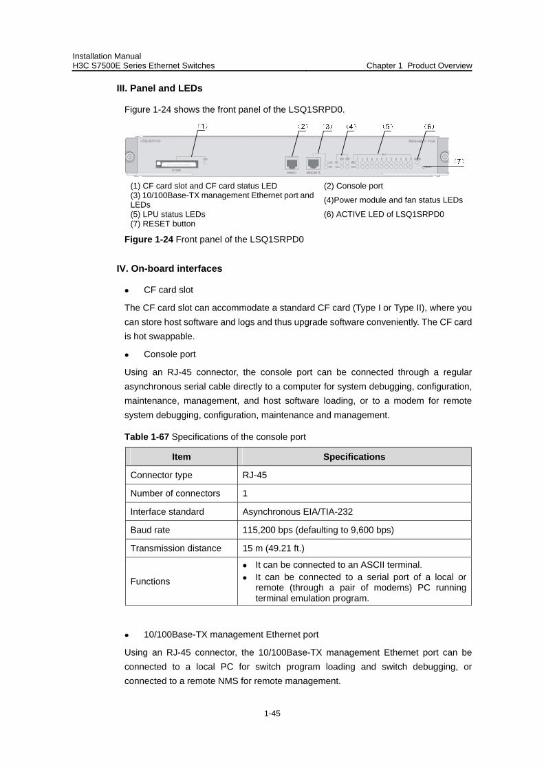
Figure 1-24 shows the front panel of the LSQ1SRPD0.
(1) CF card slot and CF card status LED (2) Console port (3) 10/100Base-TX management Ethernet port and LEDs (4)Power module and fan status LEDs
(5) LPU status LEDs (6) ACTIVE LED of LSQ1SRPD0 (7) RESET button
Figure 1-24 Front panel of the LSQ1SRPD0
IV. On-board interfaces
CF card slot
The CF card slot can accommodate a standard CF card (Type I or Type II), where you can store host software and logs and thus upgrade software conveniently. The CF card is hot swappable.
Console port
Using an RJ-45 connector, the console port can be connected through a regular asynchronous serial cable directly to a computer for system debugging, configuration, maintenance, management, and host software loading, or to a modem for remote system debugging, configuration, maintenance and management.
Table 1-67 Specifications of the console port
Item Specifications
Connector type RJ-45
Number of connectors 1
Interface standard Asynchronous EIA/TIA-232
Baud rate 115,200 bps (defaulting to 9,600 bps)
Transmission distance 15 m (49.21 ft.)
Functions
It can be connected to an ASCII terminal. It can be connected to a serial port of a local or
remote (through a pair of modems) PC running terminal emulation program.
10/100Base-TX management Ethernet port
Using an RJ-45 connector, the 10/100Base-TX management Ethernet port can be connected to a local PC for switch program loading and switch debugging, or connected to a remote NMS for remote management.
Installation Manual H3C S7500E Series Ethernet Switches Chapter 1 Product Overview
1-46
Table 1-68 Specifications of the 10/100Base-TX management Ethernet port
Item Specifications
Connector type RJ-45
Number of interfaces 1
Interface speed 10/100 Mbps, half/full duplex
Cable medium and maximum transmission distance
Category-5 twisted pair, with a maximum transmission distance of 100 m (328.08 ft.)
Function Used for switch software upgrade and network management
Table 1-69 describes the status LEDs of the 10/100Base-TX management Ethernet port.
Table 1-69 Description of the status LEDs of the 10/100Base-TX management Ethernet port
LED Description
LINK OFF: No link is present. ON: A link is present.
ACT OFF: No data is being transmitted or received. Blinking: Data is being transmitted or received.
V. System LEDs
System status LEDs
The LEDs on the card panel indicate the statuses of the power modules, fans, LPUs seated in the twelve slots, and LSQ1SRPD0 itself.
Power status LEDs
PWR: The power status LEDs show the status of the power modules.
Table 1-70 Description of the power status LEDs
LED Description
ON: The power modules operate normally. OK
OFF: The power module is faulty or out of position.
ON: The power module is faulty or out of position. FAIL
OFF: The power modules are operational or out of position.
Fan status LEDs
FAN: The LEDs show the status of the fan tray.
Installation Manual H3C S7500E Series Ethernet Switches Chapter 1 Product Overview
1-47
Table 1-71 Description of the fan status LEDs
LED Description
OK ON: The fans operate normally. OFF: The fans are faulty or out of position.
FAIL ON: The fans are faulty or out of position. OFF: The fans operate normally.
LPU status LEDs (SLOT0 through SLOT11)
SLOT0 through SLOT11: The LEDs indicate the status of the LPUs seated in the twelve slots.
Table 1-72 Description of the LPU status LEDs
LED Description
RUN ON/OFF: The LPU is faulty or out of position. Blinking: The LPU is operating normally.
ALM OFF: The LPU is operational or out of position. ON: The LPU is faulty.
Note:
If the RUN LED flashes at a high frequency, the card is in the startup process, but is not yet operational. At system startup, the ALM LED will be ON for a while, but it does not mean that the card is faulty.
ACTIVE LED
The ACTIVE LED shows the active/standby status of the LSQ1SRPD0. If the ACTIVE LED is ON, the LSQ1SRPD0 is active; if OFF, the LSQ1SRPD0 is standby.
VI. RESET button
A reset button is provided on the LSQ1SRPD0 for you to reset the card when necessary.
1.3.9 Salience VI-GE SRPU-LSQ1SRP12GB0
I. Applicable models
S7503E S7506E S7510E S7506E-V
Installation Manual H3C S7500E Series Ethernet Switches Chapter 1 Product Overview
1-48
II. Technial specifications
Table 1-73 Technical specifications of the LSQ1SR12GB0
Item Specifications
CPU Dual CPUs:
MIPS64, 600 MHz MIPS64, 400 MHz
Boot ROM 512 KB
Flash memory 64 MB
DDR SDRAM 512 MB
Dimensions (H x W x D) 45 × 377 × 355 mm (1.77 × 14.84 × 13.98 in.)
Interfaces
One CF card slot Twelve 1000Base-X-SFP/100Base-FX-SFP ports One console port, used for local or remote
configuration and management of the switch through a dialup connection
One 10/100Base-TX management Ethernet port
Power consumption 42 W to 60 W
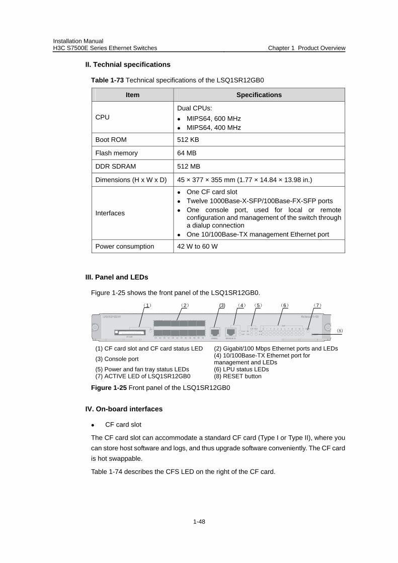
III. Panel and LEDs
Figure 1-25 shows the front panel of the LSQ1SR12GB0.
(1) (3) (4) (5) (6) (7)(2)
(8)
(1) CF card slot and CF card status LED (2) Gigabit/100 Mbps Ethernet ports and LEDs
(3) Console port (4) 10/100Base-TX Ethernet port for management and LEDs
(5) Power and fan tray status LEDs (6) LPU status LEDs (7) ACTIVE LED of LSQ1SR12GB0 (8) RESET button
Figure 1-25 Front panel of the LSQ1SR12GB0
IV. On-board interfaces
CF card slot
The CF card slot can accommodate a standard CF card (Type I or Type II), where you can store host software and logs, and thus upgrade software conveniently. The CF card is hot swappable.
Table 1-74 describes the CFS LED on the right of the CF card.
Installation Manual H3C S7500E Series Ethernet Switches Chapter 1 Product Overview
1-49
Table 1-74 Description of the CFS LED
Status Description
OFF No CF card is in position.
ON The CF card is in position.
GE/FE SFP ports
Table 1-75 presents the specifications of the GE/FE ports.
Table 1-75 Specifications of the GE/FE SFP ports
Item Specifications
Connector type SFP
Number of connectors 12
Standards
IEEE 802.3-2005 IEEE 802.1D-2004 IEEE 802.1Q-2003 IEEE 802.1X-2004
Pluggable module type Gigabit SFP module 100 Mbps SFP module
Refer to “Appendix A List of Pluggable Modules.”
Table 1-76 describes the status LEDs of the 1000Base-X-SFP/100Base-FX-SFP ports.
Table 1-76 Description of the status LEDs of the 1000Base-X-SFP/100Base-FX-SFP ports
LED Description
LINK/ACT OFF: No link is present. ON: A link is present. Blinking: Data is being transmitted or received.
Console port
Using an RJ-45 connector, the console port can be connected through a regular asynchronous serial cable directly to a computer for system debugging, configuration, maintenance, management, and host software loading, or to a modem for remote system debugging, configuration, maintenance and management.

Installation Manual H3C S7500E Series Ethernet Switches Chapter 1 Product Overview
1-50
Table 1-77 Specifications of the console port
Item Specifications
Connector type RJ-45
Number of connectors 1
Interface standard Asynchronous EIA/TIA-232
Baud rate 115,200 bps (defaulting to 9,600 bps)
Transmission distance 15 m (49.21 ft.)
Functions
It can be connected to an ASCII terminal. It can be connected to a serial port of a local or
remote (through a pair of modems) PC running terminal emulation program.
10/100Base-TX management Ethernet port
Using an RJ-45 connector, the 10/100Base-TX management Ethernet port can be connected to a local PC for switch program loading and switch debugging, or connected to a remote NMS for remote management.
Table 1-78 Specifications of the 10/100Base-TX management Ethernet port
Item Specifications
Connector type RJ-45
Number of connectors 1
Interface speed 10/100 Mbps, half/full duplex
Cable medium and maximum transmission distance
Category-5 twisted pair, with a maximum transmission distance of 100 m (328.08 ft.)
Function Used for switch software upgrade and network management
Table 1-79 describes the status LEDs of the 10/100Base-TX management Ethernet port.
Table 1-79 Description of the status LEDs of the 10/100Base-TX management Ethernet port
LED Description
LINK OFF: No link is present. ON: A link is present.
ACT OFF: No data is being transmitted or received. Blinking: Data is being transmitted or received.
Installation Manual H3C S7500E Series Ethernet Switches Chapter 1 Product Overview
1-51
V. System LEDs
System status LEDs
The LEDs on the card panel indicate the statuses of the power modules, fans, LPUs seated in the twelve slots, and LSQ1SR12GB0 itself.
Power status LEDs
PWR: The power status LEDs show the status of the power modules.
Table 1-80 Description of the power status LEDs
LED Description
ON: The power modules operate normally. OK
OFF: The power module is faulty or out of position.
ON: The power module is faulty or out of position. FAIL
OFF: The power modules are operational or out of position.
Fan status LEDs
FAN: The fan status LEDs show the status of the fan tray.
Table 1-81 Description of the fan status LEDs
LED Description
OK ON: The fans operate normally. OFF: The fans are faulty or out of position.
FAIL ON: The fans are faulty or out of position. OFF: The fans operate normally.
LPU status LEDs (SLOT0 through SLOT11)
SLOT0 through SLOT11: The LEDs indicate the status of the LPUs seated in the twelve slots.
Table 1-82 Description of the LPU status LEDs
LED Description
RUN ON/OFF: The LPU is faulty or out of position. Blinking: The LPU is operating normally.
ALM OFF: The LPU is operational or out of position. ON: The LPU is faulty.
Installation Manual H3C S7500E Series Ethernet Switches Chapter 1 Product Overview
1-52
Note:
If the RUN LED flashes at a high frequency, the card is in the startup process, but is not yet operational. At system startup, the ALM LED will be ON for a while, but it does not mean that the card is faulty.
ACTIVE LED
The ACTIVE LED shows the active/standby status of the LSQ1SR12GB0. If the ACTIVE LED is ON, the LSQ1SR12GB0 is active; if OFF, the LSQ1SR12GB0 is standby.
VI. RESET button
A reset button is provided on the LSQ1SR12GB0 for you to reset the card when necessary.
1.4 LPUs
1.4.1 LSQ1FP48SA0
I. Introduction
The LSQ1FP48SA0 provides forty-eight 100Base-FX-SFP ports.
Table 1-83 Technical specifications of the LSQ1FP48SA0
Item Specifications
CPU MIPS64, 400 MHz
Boot ROM 512 KB
DDR SDRAM 512 MB
Dimensions (H x W x D) 40 × 377 × 355 mm (1.57 × 14.84 × 13.98 in.)
Power consumption 34W to 85 W
Connector type LC
Number of ports 48
Interface speed 100 Mbps
Pluggable module type 100 Mbps SFP module Refer to “Appendix A List of Pluggable Modules.”
Standards
IEEE 802.3-2005 IEEE 802.1D-2004 IEEE 802.1Q-2003 IEEE802.1X-2004
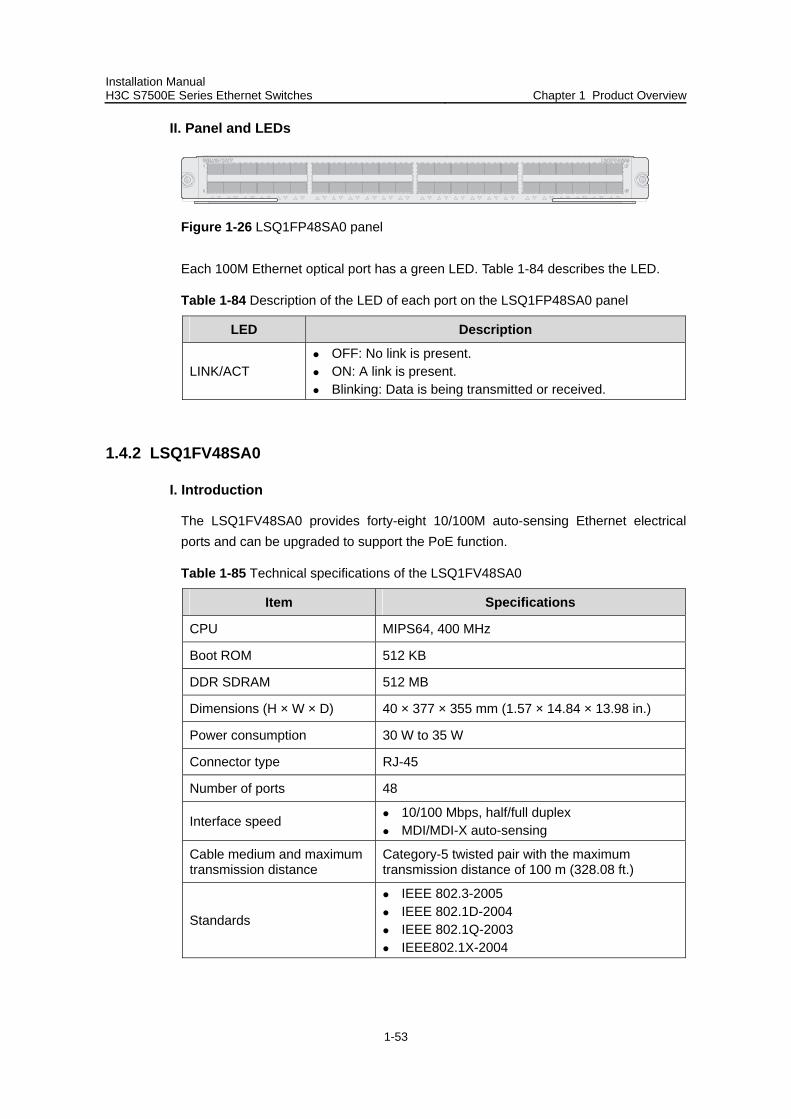
Installation Manual H3C S7500E Series Ethernet Switches Chapter 1 Product Overview
1-53
II. Panel and LEDs
Figure 1-26 LSQ1FP48SA0 panel
Each 100M Ethernet optical port has a green LED. Table 1-84 describes the LED.
Table 1-84 Description of the LED of each port on the LSQ1FP48SA0 panel
LED Description
LINK/ACT OFF: No link is present. ON: A link is present. Blinking: Data is being transmitted or received.
1.4.2 LSQ1FV48SA0
I. Introduction
The LSQ1FV48SA0 provides forty-eight 10/100M auto-sensing Ethernet electrical ports and can be upgraded to support the PoE function.
Table 1-85 Technical specifications of the LSQ1FV48SA0
Item Specifications
CPU MIPS64, 400 MHz
Boot ROM 512 KB
DDR SDRAM 512 MB
Dimensions (H × W × D) 40 × 377 × 355 mm (1.57 × 14.84 × 13.98 in.)
Power consumption 30 W to 35 W
Connector type RJ-45
Number of ports 48
Interface speed 10/100 Mbps, half/full duplex MDI/MDI-X auto-sensing
Cable medium and maximum transmission distance
Category-5 twisted pair with the maximum transmission distance of 100 m (328.08 ft.)
Standards
IEEE 802.3-2005 IEEE 802.1D-2004 IEEE 802.1Q-2003 IEEE802.1X-2004
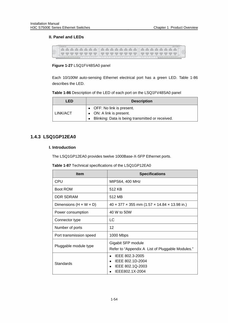
Installation Manual H3C S7500E Series Ethernet Switches Chapter 1 Product Overview
1-54
II. Panel and LEDs
Figure 1-27 LSQ1FV48SA0 panel
Each 10/100M auto-sensing Ethernet electrical port has a green LED. Table 1-86 describes the LED.
Table 1-86 Description of the LED of each port on the LSQ1FV48SA0 panel
LED Description
LINK/ACT OFF: No link is present. ON: A link is present. Blinking: Data is being transmitted or received.
1.4.3 LSQ1GP12EA0
I. Introduction
The LSQ1GP12EA0 provides twelve 1000Base-X-SFP Ethernet ports.
Table 1-87 Technical specifications of the LSQ1GP12EA0
Item Specifications
CPU MIPS64, 400 MHz
Boot ROM 512 KB
DDR SDRAM 512 MB
Dimensions (H × W × D) 40 × 377 × 355 mm (1.57 × 14.84 × 13.98 in.)
Power consumption 40 W to 50W
Connector type LC
Number of ports 12
Port transmission speed 1000 Mbps
Pluggable module type Gigabit SFP module Refer to “Appendix A List of Pluggable Modules.”
Standards
IEEE 802.3-2005 IEEE 802.1D-2004 IEEE 802.1Q-2003 IEEE802.1X-2004
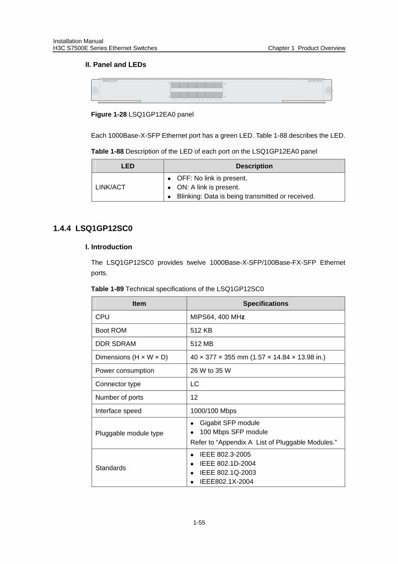
Installation Manual H3C S7500E Series Ethernet Switches Chapter 1 Product Overview
1-55
II. Panel and LEDs
Figure 1-28 LSQ1GP12EA0 panel
Each 1000Base-X-SFP Ethernet port has a green LED. Table 1-88 describes the LED.
Table 1-88 Description of the LED of each port on the LSQ1GP12EA0 panel
LED Description
LINK/ACT OFF: No link is present. ON: A link is present. Blinking: Data is being transmitted or received.
1.4.4 LSQ1GP12SC0
I. Introduction
The LSQ1GP12SC0 provides twelve 1000Base-X-SFP/100Base-FX-SFP Ethernet ports.
Table 1-89 Technical specifications of the LSQ1GP12SC0
Item Specifications
CPU MIPS64, 400 MHz
Boot ROM 512 KB
DDR SDRAM 512 MB
Dimensions (H × W × D) 40 × 377 × 355 mm (1.57 × 14.84 × 13.98 in.)
Power consumption 26 W to 35 W
Connector type LC
Number of ports 12
Interface speed 1000/100 Mbps
Pluggable module type Gigabit SFP module 100 Mbps SFP module
Refer to “Appendix A List of Pluggable Modules.”
Standards
IEEE 802.3-2005 IEEE 802.1D-2004 IEEE 802.1Q-2003 IEEE802.1X-2004
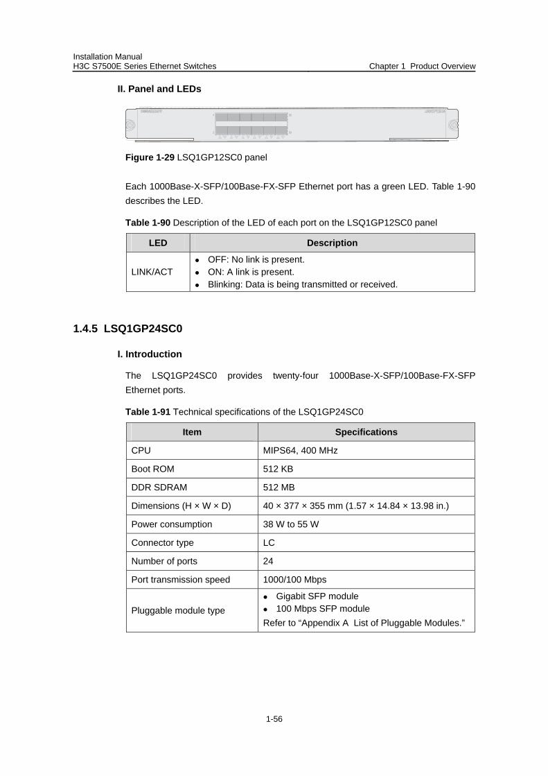
Installation Manual H3C S7500E Series Ethernet Switches Chapter 1 Product Overview
1-56
II. Panel and LEDs
Figure 1-29 LSQ1GP12SC0 panel
Each 1000Base-X-SFP/100Base-FX-SFP Ethernet port has a green LED. Table 1-90 describes the LED.
Table 1-90 Description of the LED of each port on the LSQ1GP12SC0 panel
LED Description
LINK/ACT OFF: No link is present. ON: A link is present. Blinking: Data is being transmitted or received.
1.4.5 LSQ1GP24SC0
I. Introduction
The LSQ1GP24SC0 provides twenty-four 1000Base-X-SFP/100Base-FX-SFP Ethernet ports.
Table 1-91 Technical specifications of the LSQ1GP24SC0
Item Specifications
CPU MIPS64, 400 MHz
Boot ROM 512 KB
DDR SDRAM 512 MB
Dimensions (H × W × D) 40 × 377 × 355 mm (1.57 × 14.84 × 13.98 in.)
Power consumption 38 W to 55 W
Connector type LC
Number of ports 24
Port transmission speed 1000/100 Mbps
Pluggable module type Gigabit SFP module 100 Mbps SFP module
Refer to “Appendix A List of Pluggable Modules.”
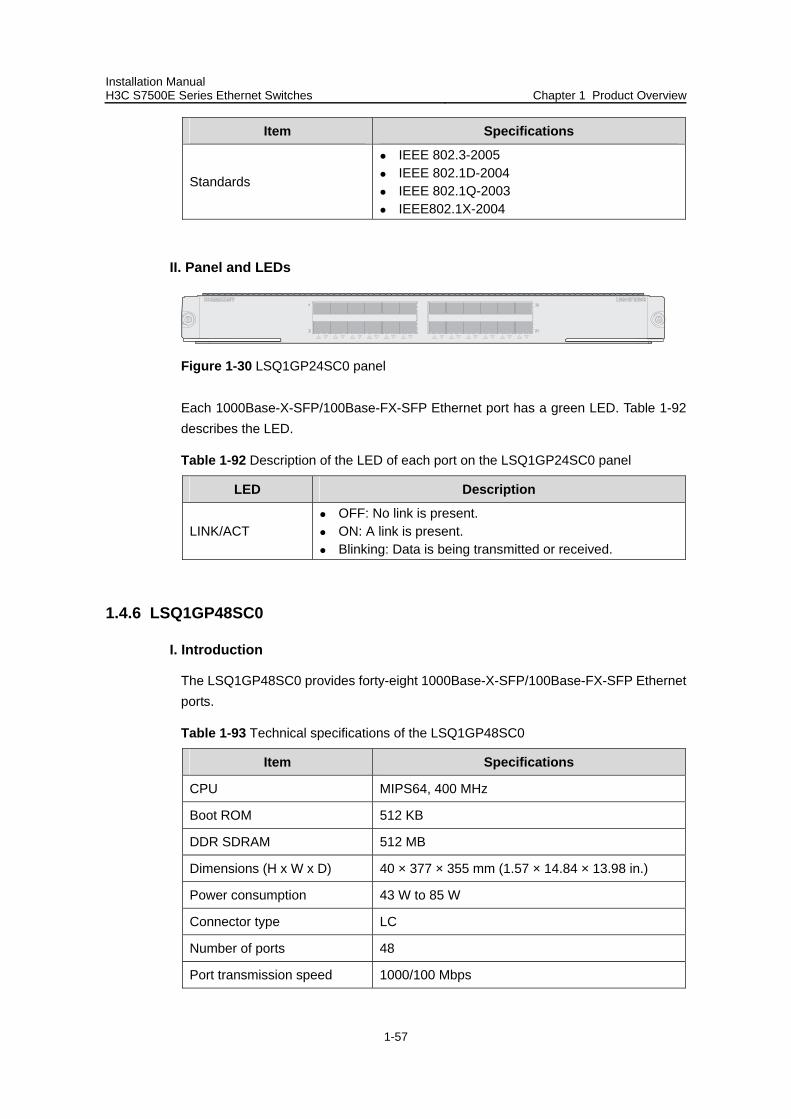
Installation Manual H3C S7500E Series Ethernet Switches Chapter 1 Product Overview
1-57
Item Specifications
Standards
IEEE 802.3-2005 IEEE 802.1D-2004 IEEE 802.1Q-2003 IEEE802.1X-2004
II. Panel and LEDs
Figure 1-30 LSQ1GP24SC0 panel
Each 1000Base-X-SFP/100Base-FX-SFP Ethernet port has a green LED. Table 1-92 describes the LED.
Table 1-92 Description of the LED of each port on the LSQ1GP24SC0 panel
LED Description
LINK/ACT OFF: No link is present. ON: A link is present. Blinking: Data is being transmitted or received.
1.4.6 LSQ1GP48SC0
I. Introduction
The LSQ1GP48SC0 provides forty-eight 1000Base-X-SFP/100Base-FX-SFP Ethernet ports.
Table 1-93 Technical specifications of the LSQ1GP48SC0
Item Specifications
CPU MIPS64, 400 MHz
Boot ROM 512 KB
DDR SDRAM 512 MB
Dimensions (H x W x D) 40 × 377 × 355 mm (1.57 × 14.84 × 13.98 in.)
Power consumption 43 W to 85 W
Connector type LC
Number of ports 48
Port transmission speed 1000/100 Mbps

Installation Manual H3C S7500E Series Ethernet Switches Chapter 1 Product Overview
1-58
Item Specifications
Pluggable module type Gigabit SFP module 100 Mbps SFP module
Refer to “Appendix A List of Pluggable Modules.”
Standard
IEEE 802.3-2005 IEEE 802.1D-2004 IEEE 802.1Q-2003 IEEE802.1X-2004
II. Panel and LEDs
Figure 1-31 LSQ1GP48SC0 panel
Each 1000Base-X-SFP/100Base-FX-SFP Ethernet port has a green LED. Table 1-94 describes the LED.
Table 1-94 Description of the LED of each port on the LSQ1GP48SC0 panel
LED Description
LINK/ACT OFF: No link is present. ON: A link is present. Blinking: Data is being transmitted or received.
1.4.7 LSQ1GT24SC0
I. Introduction
The LSQ1GT24SC0 provides twenty-four 10/100/1000M autosensing Ethernet electrical ports.
Table 1-95 Technical specifications of the LSQ1GT24SC0
Item Specifications
CPU MIPS64, 400 MHz
Boot ROM 512 KB
DDR SDRAM 512 MB
Dimensions (H x W x D) 40 × 377 × 355 mm (1.57 × 14.84 × 13.98 in.)
Power consumption 42 W to 50 W
Connector type RJ-45
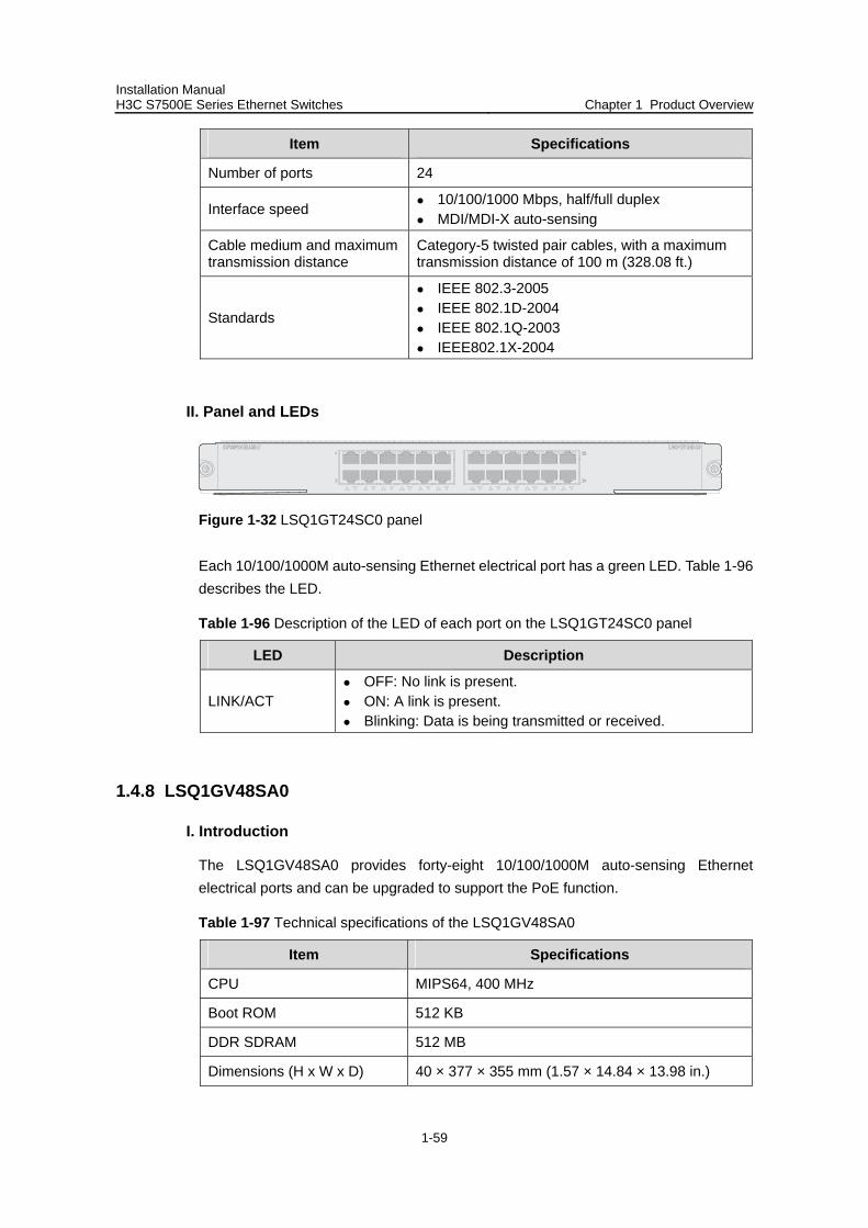
Installation Manual H3C S7500E Series Ethernet Switches Chapter 1 Product Overview
1-59
Item Specifications
Number of ports 24
Interface speed 10/100/1000 Mbps, half/full duplex MDI/MDI-X auto-sensing
Cable medium and maximum transmission distance
Category-5 twisted pair cables, with a maximum transmission distance of 100 m (328.08 ft.)
Standards
IEEE 802.3-2005 IEEE 802.1D-2004 IEEE 802.1Q-2003 IEEE802.1X-2004
II. Panel and LEDs
Figure 1-32 LSQ1GT24SC0 panel
Each 10/100/1000M auto-sensing Ethernet electrical port has a green LED. Table 1-96 describes the LED.
Table 1-96 Description of the LED of each port on the LSQ1GT24SC0 panel
LED Description
LINK/ACT OFF: No link is present. ON: A link is present. Blinking: Data is being transmitted or received.
1.4.8 LSQ1GV48SA0
I. Introduction
The LSQ1GV48SA0 provides forty-eight 10/100/1000M auto-sensing Ethernet electrical ports and can be upgraded to support the PoE function.
Table 1-97 Technical specifications of the LSQ1GV48SA0
Item Specifications
CPU MIPS64, 400 MHz
Boot ROM 512 KB
DDR SDRAM 512 MB
Dimensions (H x W x D) 40 × 377 × 355 mm (1.57 × 14.84 × 13.98 in.)
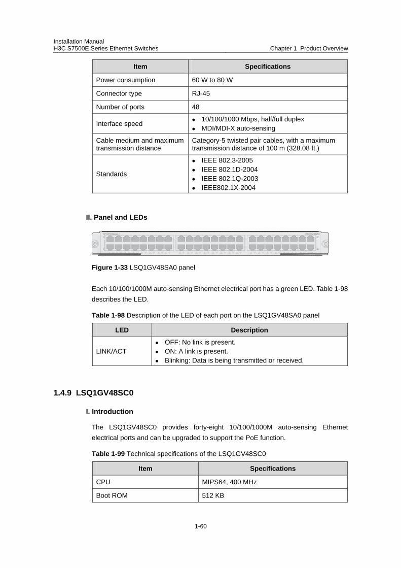
Installation Manual H3C S7500E Series Ethernet Switches Chapter 1 Product Overview
1-60
Item Specifications
Power consumption 60 W to 80 W
Connector type RJ-45
Number of ports 48
Interface speed 10/100/1000 Mbps, half/full duplex MDI/MDI-X auto-sensing
Cable medium and maximum transmission distance
Category-5 twisted pair cables, with a maximum transmission distance of 100 m (328.08 ft.)
Standards
IEEE 802.3-2005 IEEE 802.1D-2004 IEEE 802.1Q-2003 IEEE802.1X-2004
II. Panel and LEDs
Figure 1-33 LSQ1GV48SA0 panel
Each 10/100/1000M auto-sensing Ethernet electrical port has a green LED. Table 1-98 describes the LED.
Table 1-98 Description of the LED of each port on the LSQ1GV48SA0 panel
LED Description
LINK/ACT OFF: No link is present. ON: A link is present. Blinking: Data is being transmitted or received.
1.4.9 LSQ1GV48SC0
I. Introduction
The LSQ1GV48SC0 provides forty-eight 10/100/1000M auto-sensing Ethernet electrical ports and can be upgraded to support the PoE function.
Table 1-99 Technical specifications of the LSQ1GV48SC0
Item Specifications
CPU MIPS64, 400 MHz
Boot ROM 512 KB
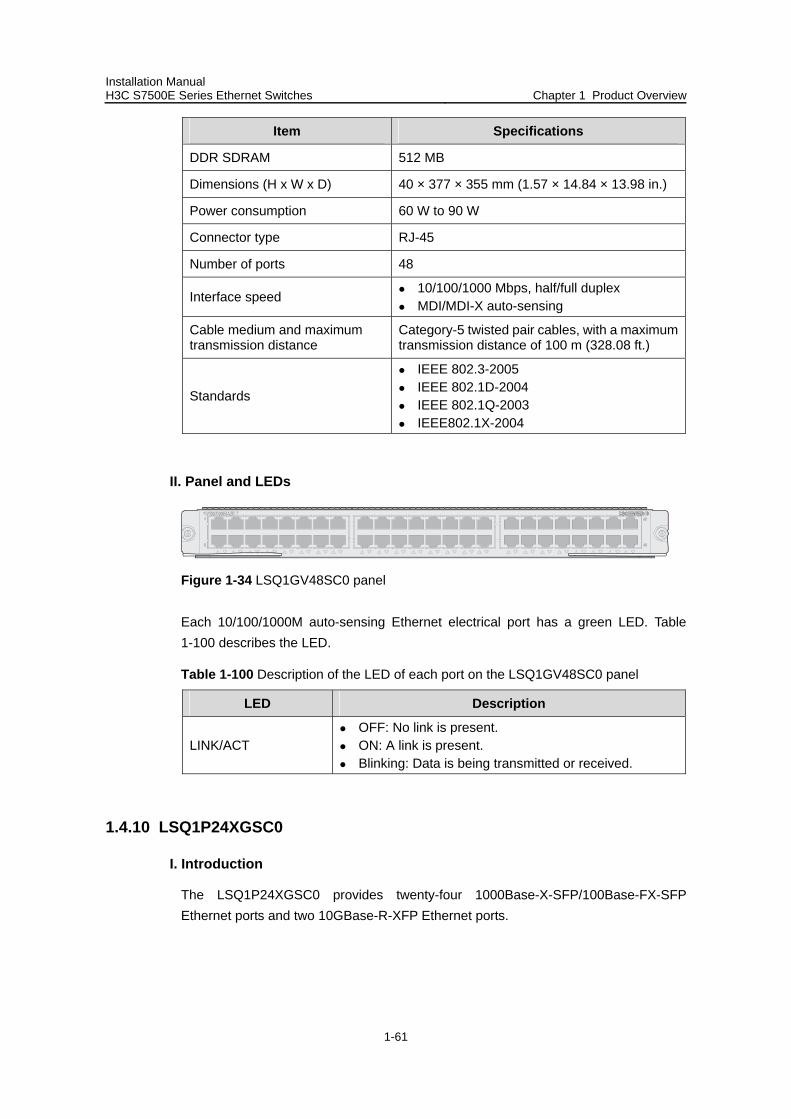
Installation Manual H3C S7500E Series Ethernet Switches Chapter 1 Product Overview
1-61
Item Specifications
DDR SDRAM 512 MB
Dimensions (H x W x D) 40 × 377 × 355 mm (1.57 × 14.84 × 13.98 in.)
Power consumption 60 W to 90 W
Connector type RJ-45
Number of ports 48
Interface speed 10/100/1000 Mbps, half/full duplex MDI/MDI-X auto-sensing
Cable medium and maximum transmission distance
Category-5 twisted pair cables, with a maximum transmission distance of 100 m (328.08 ft.)
Standards
IEEE 802.3-2005 IEEE 802.1D-2004 IEEE 802.1Q-2003 IEEE802.1X-2004
II. Panel and LEDs
Figure 1-34 LSQ1GV48SC0 panel
Each 10/100/1000M auto-sensing Ethernet electrical port has a green LED. Table 1-100 describes the LED.
Table 1-100 Description of the LED of each port on the LSQ1GV48SC0 panel
LED Description
LINK/ACT OFF: No link is present. ON: A link is present. Blinking: Data is being transmitted or received.
1.4.10 LSQ1P24XGSC0
I. Introduction
The LSQ1P24XGSC0 provides twenty-four 1000Base-X-SFP/100Base-FX-SFP Ethernet ports and two 10GBase-R-XFP Ethernet ports.
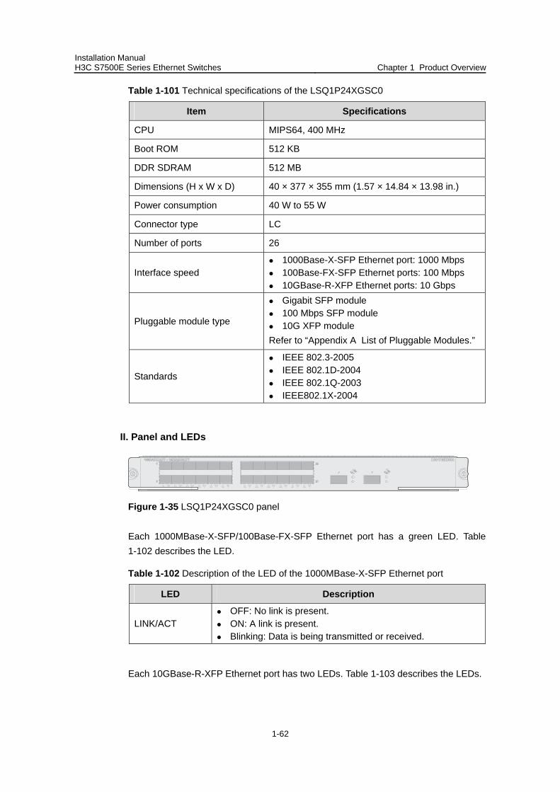
Installation Manual H3C S7500E Series Ethernet Switches Chapter 1 Product Overview
1-62
Table 1-101 Technical specifications of the LSQ1P24XGSC0
Item Specifications
CPU MIPS64, 400 MHz
Boot ROM 512 KB
DDR SDRAM 512 MB
Dimensions (H x W x D) 40 × 377 × 355 mm (1.57 × 14.84 × 13.98 in.)
Power consumption 40 W to 55 W
Connector type LC
Number of ports 26
Interface speed 1000Base-X-SFP Ethernet port: 1000 Mbps 100Base-FX-SFP Ethernet ports: 100 Mbps 10GBase-R-XFP Ethernet ports: 10 Gbps
Pluggable module type
Gigabit SFP module 100 Mbps SFP module 10G XFP module
Refer to “Appendix A List of Pluggable Modules.”
Standards
IEEE 802.3-2005 IEEE 802.1D-2004 IEEE 802.1Q-2003 IEEE802.1X-2004
II. Panel and LEDs
Figure 1-35 LSQ1P24XGSC0 panel
Each 1000MBase-X-SFP/100Base-FX-SFP Ethernet port has a green LED. Table 1-102 describes the LED.
Table 1-102 Description of the LED of the 1000MBase-X-SFP Ethernet port
LED Description
LINK/ACT OFF: No link is present. ON: A link is present. Blinking: Data is being transmitted or received.
Each 10GBase-R-XFP Ethernet port has two LEDs. Table 1-103 describes the LEDs.
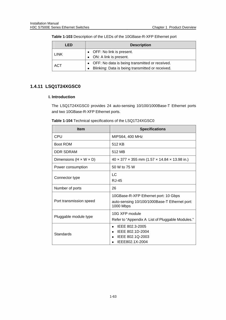
Installation Manual H3C S7500E Series Ethernet Switches Chapter 1 Product Overview
1-63
Table 1-103 Description of the LEDs of the 10GBase-R-XFP Ethernet port
LED Description
LINK OFF: No link is present. ON: A link is present.
ACT OFF: No data is being transmitted or received. Blinking: Data is being transmitted or received.
1.4.11 LSQ1T24XGSC0
I. Introduction
The LSQ1T24XGSC0 provides 24 auto-sensing 10/100/1000Base-T Ethernet ports and two 10GBase-R-XFP Ethernet ports.
Table 1-104 Technical specifications of the LSQ1T24XGSC0
Item Specifications
CPU MIPS64, 400 MHz
Boot ROM 512 KB
DDR SDRAM 512 MB
Dimensions (H × W × D) 40 × 377 × 355 mm (1.57 × 14.84 × 13.98 in.)
Power consumption 50 W to 75 W
Connector type LC RJ-45
Number of ports 26
Port transmission speed 10GBase-R-XFP Ethernet port: 10 Gbps auto-sensing 10/100/1000Base-T Ethernet port: 1000 Mbps
Pluggable module type 10G XFP module Refer to “Appendix A List of Pluggable Modules.”
Standards
IEEE 802.3-2005 IEEE 802.1D-2004 IEEE 802.1Q-2003 IEEE802.1X-2004
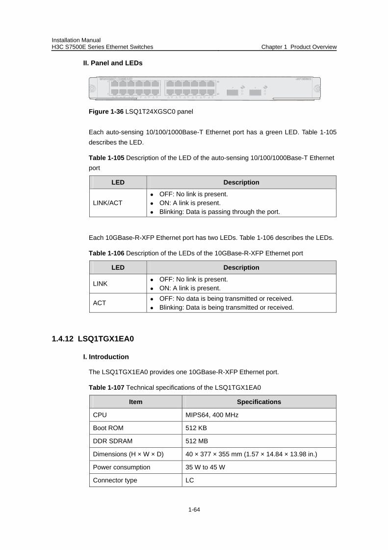
Installation Manual H3C S7500E Series Ethernet Switches Chapter 1 Product Overview
1-64
II. Panel and LEDs
Figure 1-36 LSQ1T24XGSC0 panel
Each auto-sensing 10/100/1000Base-T Ethernet port has a green LED. Table 1-105 describes the LED.
Table 1-105 Description of the LED of the auto-sensing 10/100/1000Base-T Ethernet port
LED Description
LINK/ACT OFF: No link is present. ON: A link is present. Blinking: Data is passing through the port.
Each 10GBase-R-XFP Ethernet port has two LEDs. Table 1-106 describes the LEDs.
Table 1-106 Description of the LEDs of the 10GBase-R-XFP Ethernet port
LED Description
LINK OFF: No link is present. ON: A link is present.
ACT OFF: No data is being transmitted or received. Blinking: Data is being transmitted or received.
1.4.12 LSQ1TGX1EA0
I. Introduction
The LSQ1TGX1EA0 provides one 10GBase-R-XFP Ethernet port.
Table 1-107 Technical specifications of the LSQ1TGX1EA0
Item Specifications
CPU MIPS64, 400 MHz
Boot ROM 512 KB
DDR SDRAM 512 MB
Dimensions (H × W × D) 40 × 377 × 355 mm (1.57 × 14.84 × 13.98 in.)
Power consumption 35 W to 45 W
Connector type LC
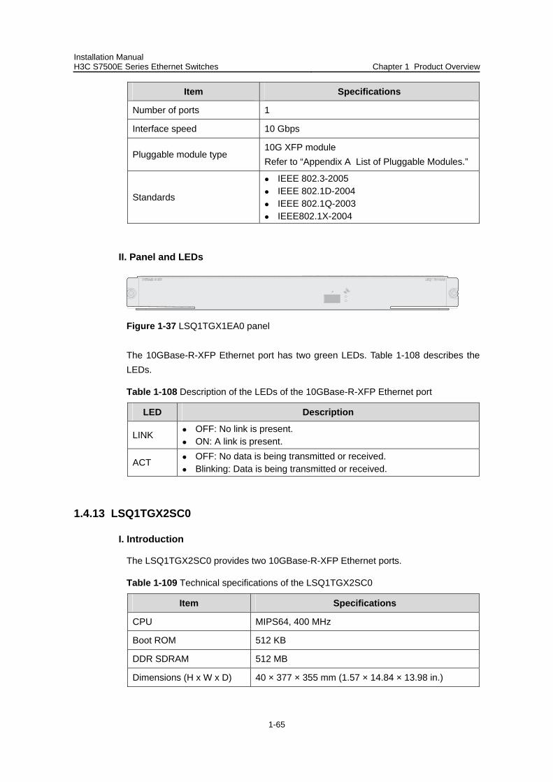
Installation Manual H3C S7500E Series Ethernet Switches Chapter 1 Product Overview
1-65
Item Specifications
Number of ports 1
Interface speed 10 Gbps
Pluggable module type 10G XFP module Refer to “Appendix A List of Pluggable Modules.”
Standards
IEEE 802.3-2005 IEEE 802.1D-2004 IEEE 802.1Q-2003 IEEE802.1X-2004
II. Panel and LEDs
Figure 1-37 LSQ1TGX1EA0 panel
The 10GBase-R-XFP Ethernet port has two green LEDs. Table 1-108 describes the LEDs.
Table 1-108 Description of the LEDs of the 10GBase-R-XFP Ethernet port
LED Description
LINK OFF: No link is present. ON: A link is present.
ACT OFF: No data is being transmitted or received. Blinking: Data is being transmitted or received.
1.4.13 LSQ1TGX2SC0
I. Introduction
The LSQ1TGX2SC0 provides two 10GBase-R-XFP Ethernet ports.
Table 1-109 Technical specifications of the LSQ1TGX2SC0
Item Specifications
CPU MIPS64, 400 MHz
Boot ROM 512 KB
DDR SDRAM 512 MB
Dimensions (H x W x D) 40 × 377 × 355 mm (1.57 × 14.84 × 13.98 in.)
Installation Manual H3C S7500E Series Ethernet Switches Chapter 1 Product Overview
1-66
Item Specifications
Power consumption 30 W to 40 W
Connector type LC
Number of ports 2
Interface speed 10 Gbps
Pluggable module type 10G XFP module Refer to “Appendix A List of Pluggable Modules.”
Standards
IEEE 802.3-2005 IEEE 802.1D-2004 IEEE 802.1Q-2003 IEEE802.1X-2004
II. Panel and LEDs
Figure 1-38 LSQ1TGX2SC0 panel
Each 10GBase-X-XFP Ethernet port has two green LEDs. Table 1-110 describes the LEDs on the LSQ1TGX2SC0 panel.
Table 1-110 Description of the LEDs of the 10GBase-X-XFP Ethernet port
LED Description
LINK OFF: No link is present. ON: A link is present.
ACT OFF: No data is being transmitted or received. Blinking: Data is being transmitted or received.
1.4.14 LSQ1GP24TSC0
I. Introduciton
The LSQ1GP24TSC0 provides twenty-four 1000Base-X-SFP/100Base-FX-SFP Ethernet ports and eight 10/100/1000Base-T GE ports. The eight GE ports and eight of the SFP ports can form eight Combo ports, each comprising a GE port and an SFP port.
Installation Manual H3C S7500E Series Ethernet Switches Chapter 1 Product Overview
1-67
Table 1-111 Technical specifications of the LSQ1GP24TSC0
Item Specifications
CPU MIPS64, 400 MHz
Boot ROM 512 KB
DDR SDRAM 512 MB
Dimensions (H x W x D) 40 × 377 × 355 mm (1.57 × 14.84 × 13.98 in.)
Power consumption 25 W to 45 W
Connector type SFP RJ-45
Number of ports 24 SFP + 8 RJ-45
Interface speed
1000Base-X-SFP Ethernet ports: 1000 Mbps 100Base-FX-SFP Ethernet ports: 100 Mbps Ethernet electrical ports:
10/100/1000 Mbps, half/full duplex MDI/MDI-X auto-sensing
Pluggable module type
Gigabit SFP module 100 Mbps SFP module 10/100/1000 Mbps auto-sensing electrical
Ethernet port Refer to “Appendix A List of Pluggable Modules.”
Standards
IEEE 802.3-2005 IEEE 802.1D-2004 IEEE 802.1Q-2003 IEEE802.1X-2004
Table 1-112 shows the pairings of the eight SFP and the eight GE ports for the Combo interfaces.
Table 1-112 Pairings of the SFP ports and the GE ports for the Combo interfaces
1000Base-X-SFP/100Base-FX-SFP Ethernet port number
10/100/1000Base-T GE port number
17 25
18 26
19 27
20 28
21 29
22 30
Installation Manual H3C S7500E Series Ethernet Switches Chapter 1 Product Overview
1-68
1000Base-X-SFP/100Base-FX-SFP Ethernet port number
10/100/1000Base-T GE port number
23 31
24 32
Note:
In a Combo port, only one of the 1000Base-X-SFP/100Base-FX-SFP port and the 10/100/1000Base-T GE port can be used at a time.
II. Panel and LEDs
Figure 1-39 LSQ1GP24TSC0 panel
Each Ethernet port has one green LED. Table 1-113 describes the LEDs on the LSQ1GP24TSC0 panel.
Table 1-113 Description of the LED of each Ethernet port
LED Description
LINK/ACT OFF: No link is present. ON: A link is present. Blinking: Data is being transmitted or received.
1.4.15 LSQ1GV40PSC0
I. Introduction
The LSQ1GV40PSC0 provides forty electrical GE ports and eight 1000Base-X-SFP/ 100Base-FX-SFP ports.
Table 1-114 Technical specifications of the LSQ1GV40PSC0
Item Specifications
CPU MIPS64, 400 MHz
Boot ROM 512 KB
DDR SDRAM 512 MB
Dimensions (H x W x D) 40 × 377 × 355 mm (1.57 × 14.84 × 13.98 in.)
Installation Manual H3C S7500E Series Ethernet Switches Chapter 1 Product Overview
1-69
Item Specifications
Power consumption 41 W to 95 W
Connector type SFP RJ-45
Number of ports 40 RJ-45 + 8 SFP
Interface speed Electrical GE port: 10/100/1000 Mbps Gigabit SFP port: 100/1000 Mbps
Pluggable module type
Gigabit SFP module 100 Mbps SFP module Auto-sensing 10/100/1000Base-T Ethernet port
Refer to “Appendix A List of Pluggable Modules.”
Standards
IEEE 802.3-2005 IEEE 802.1D-2004 IEEE 802.1Q-2003 IEEE802.1X-2004
II. Panel and LEDs
Figure 1-40 LSQ1GV40PSC0 panel
Each Ethernet port has a green LED. Table 1-115 describes the LEDs on the LSQ1GV40PSC0 panel.
Table 1-115 Description of the LED of each Ethernet port
LED Description
LINK/ACT OFF: No link is present. ON: A link is present. Blinking: Data is being transmitted or received.
1.4.16 LSQ1PT4PSC0
I. Introduction
The LSQ1PT4PSC0 provides four 1000Base-PX-D (EPON) ports and eight 1000Base-X-SFP/100Base-FX-SFP Ethernet ports.
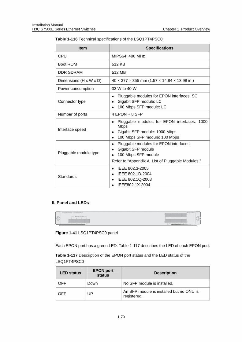
Installation Manual H3C S7500E Series Ethernet Switches Chapter 1 Product Overview
1-70
Table 1-116 Technical specifications of the LSQ1PT4PSC0
Item Specifications
CPU MIPS64, 400 MHz
Boot ROM 512 KB
DDR SDRAM 512 MB
Dimensions (H x W x D) 40 × 377 × 355 mm (1.57 × 14.84 × 13.98 in.)
Power consumption 33 W to 40 W
Connector type Pluggable modules for EPON interfaces: SC Gigabit SFP module: LC 100 Mbps SFP module: LC
Number of ports 4 EPON + 8 SFP
Interface speed
Pluggable modules for EPON interfaces: 1000 Mbps
Gigabit SFP module: 1000 Mbps 100 Mbps SFP module: 100 Mbps
Pluggable module type
Pluggable modules for EPON interfaces Gigabit SFP module 100 Mbps SFP module
Refer to “Appendix A List of Pluggable Modules.”
Standards
IEEE 802.3-2005 IEEE 802.1D-2004 IEEE 802.1Q-2003 IEEE802.1X-2004
II. Panel and LEDs
Figure 1-41 LSQ1PT4PSC0 panel
Each EPON port has a green LED. Table 1-117 describes the LED of each EPON port.
Table 1-117 Description of the EPON port status and the LED status of the LSQ1PT4PSC0
LED status EPON port status Description
OFF Down No SFP module is installed.
OFF UP An SFP module is installed but no ONU is registered.
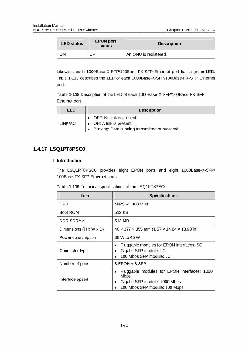
Installation Manual H3C S7500E Series Ethernet Switches Chapter 1 Product Overview
1-71
LED status EPON port status Description
ON UP An ONU is registered.
Likewise, each 1000Base-X-SFP/100Base-FX-SFP Ethernet port has a green LED. Table 1-118 describes the LED of each 1000Base-X-SFP/100Base-FX-SFP Ethernet port.
Table 1-118 Description of the LED of each 1000Base-X-SFP/100Base-FX-SFP Ethernet port
LED Description
LINK/ACT OFF: No link is present. ON: A link is present. Blinking: Data is being transmitted or received.
1.4.17 LSQ1PT8PSC0
I. Introduction
The LSQ1PT8PSC0 provides eight EPON ports and eight 1000Base-X-SFP/ 100Base-FX-SFP Ethernet ports.
Table 1-119 Technical specifications of the LSQ1PT8PSC0
Item Specifications
CPU MIPS64, 400 MHz
Boot ROM 512 KB
DDR SDRAM 512 MB
Dimensions (H x W x D) 40 × 377 × 355 mm (1.57 × 14.84 × 13.98 in.)
Power consumption 38 W to 45 W
Connector type Pluggable modules for EPON interfaces: SC Gigabit SFP module: LC 100 Mbps SFP module: LC
Number of ports 8 EPON + 8 SFP
Interface speed
Pluggable modules for EPON interfaces: 1000 Mbps
Gigabit SFP module: 1000 Mbps 100 Mbps SFP module: 100 Mbps
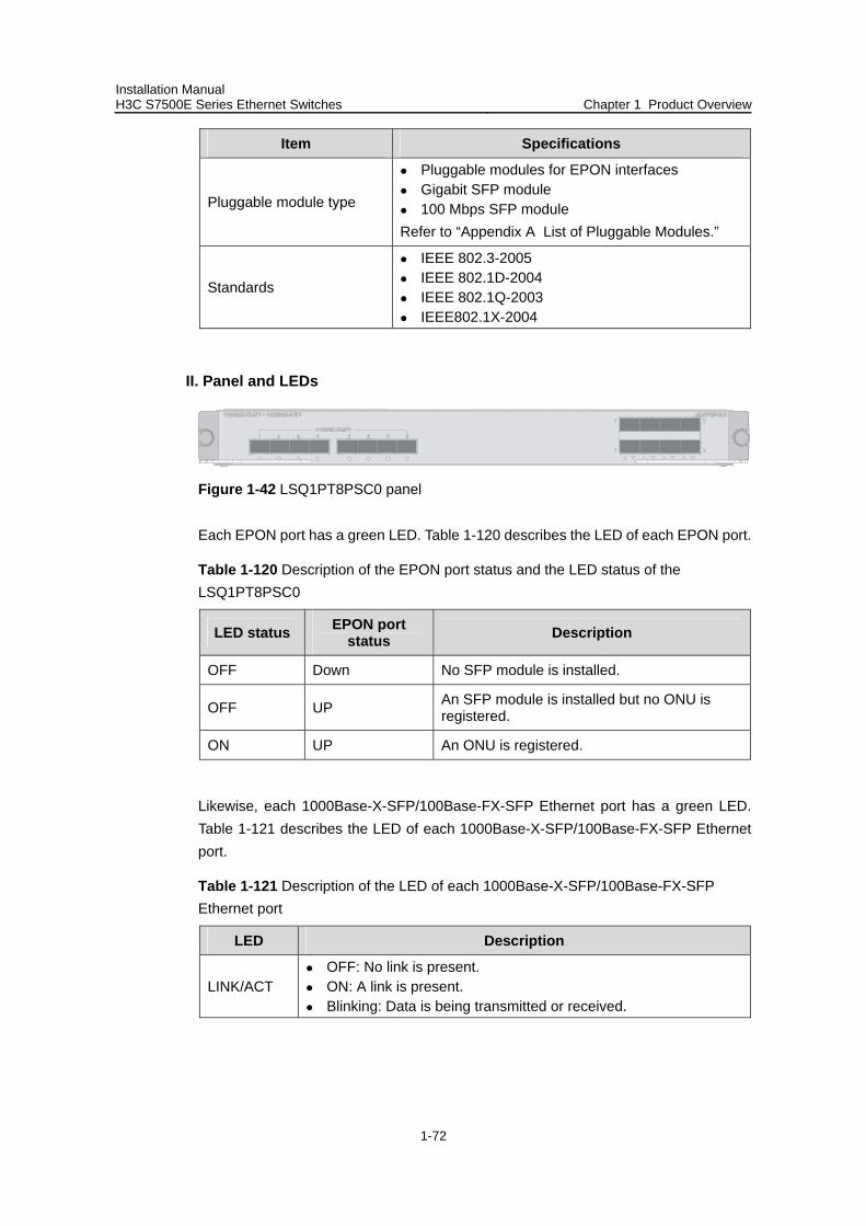
Installation Manual H3C S7500E Series Ethernet Switches Chapter 1 Product Overview
1-72
Item Specifications
Pluggable module type
Pluggable modules for EPON interfaces Gigabit SFP module 100 Mbps SFP module
Refer to “Appendix A List of Pluggable Modules.”
Standards
IEEE 802.3-2005 IEEE 802.1D-2004 IEEE 802.1Q-2003 IEEE802.1X-2004
II. Panel and LEDs
Figure 1-42 LSQ1PT8PSC0 panel
Each EPON port has a green LED. Table 1-120 describes the LED of each EPON port.
Table 1-120 Description of the EPON port status and the LED status of the LSQ1PT8PSC0
LED status EPON port status Description
OFF Down No SFP module is installed.
OFF UP An SFP module is installed but no ONU is registered.
ON UP An ONU is registered.
Likewise, each 1000Base-X-SFP/100Base-FX-SFP Ethernet port has a green LED. Table 1-121 describes the LED of each 1000Base-X-SFP/100Base-FX-SFP Ethernet port.
Table 1-121 Description of the LED of each 1000Base-X-SFP/100Base-FX-SFP Ethernet port
LED Description
LINK/ACT OFF: No link is present. ON: A link is present. Blinking: Data is being transmitted or received.
Installation Manual H3C S7500E Series Ethernet Switches Chapter 1 Product Overview
1-73
1.4.18 LSQ1PT16PSC0
I. Introduction
The LSQ1PT16PSC0 provides sixteen EPON ports and eight 1000Base-X-SFP/ 100Base-FX-SFP Ethernet ports.
Table 1-122 Technical specifications of the LSQ1PT16PSC0
Item Specifications
CPU MIPS64, 400 MHz
Boot ROM 512 KB
DDR SDRAM 512 MB
Dimensions (H x W x D) 40 × 377 × 355 mm (1.57 × 14.84 × 13.98 in.)
Power consumption 55 W to 65 W
Connector type Pluggable modules for EPON interfaces: SC Gigabit SFP module: LC 100 Mbps SFP module: LC
Number of ports 16 EPON + 8 SFP
Interface speed Pluggable modules for EPON interfaces: 1000 Mbps Gigabit SFP module: 1000 Mbps 100 Mbps SFP module: 100 Mbps
Pluggable module type
Pluggable modules for EPON interfaces Gigabit SFP module 100 Mbps SFP module
Refer to “Appendix A List of Pluggable Modules.”
Standards
IEEE 802.3-2005 IEEE 802.1D-2004 IEEE 802.1Q-2003 IEEE802.1X-2004
II. Panel and LEDs
Figure 1-43 LSQ1PT16PSC0 panel
Each EPON port has a green LED. Table 1-123 describes the LED of each EPON port.
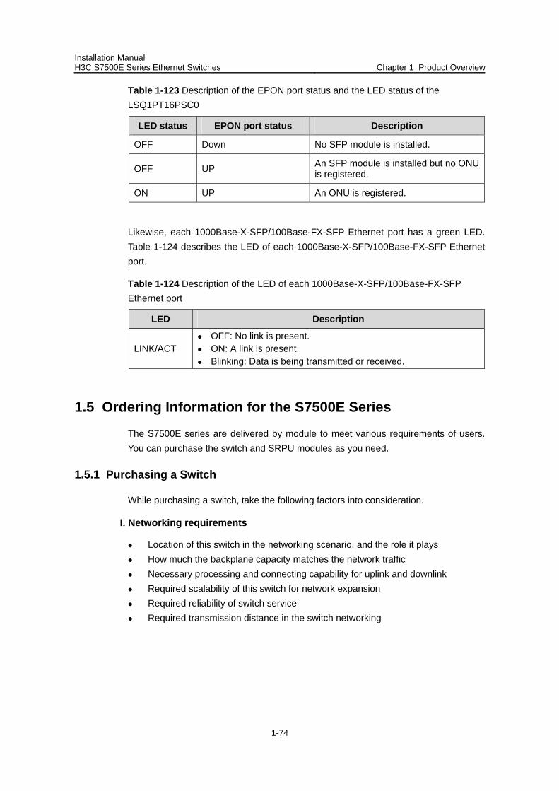
Installation Manual H3C S7500E Series Ethernet Switches Chapter 1 Product Overview
1-74
Table 1-123 Description of the EPON port status and the LED status of the LSQ1PT16PSC0
LED status EPON port status Description
OFF Down No SFP module is installed.
OFF UP An SFP module is installed but no ONU is registered.
ON UP An ONU is registered.
Likewise, each 1000Base-X-SFP/100Base-FX-SFP Ethernet port has a green LED. Table 1-124 describes the LED of each 1000Base-X-SFP/100Base-FX-SFP Ethernet port.
Table 1-124 Description of the LED of each 1000Base-X-SFP/100Base-FX-SFP Ethernet port
LED Description
LINK/ACT OFF: No link is present. ON: A link is present. Blinking: Data is being transmitted or received.
1.5 Ordering Information for the S7500E Series
The S7500E series are delivered by module to meet various requirements of users. You can purchase the switch and SRPU modules as you need.
1.5.1 Purchasing a Switch
While purchasing a switch, take the following factors into consideration.
I. Networking requirements
Location of this switch in the networking scenario, and the role it plays How much the backplane capacity matches the network traffic Necessary processing and connecting capability for uplink and downlink Required scalability of this switch for network expansion Required reliability of switch service Required transmission distance in the switch networking
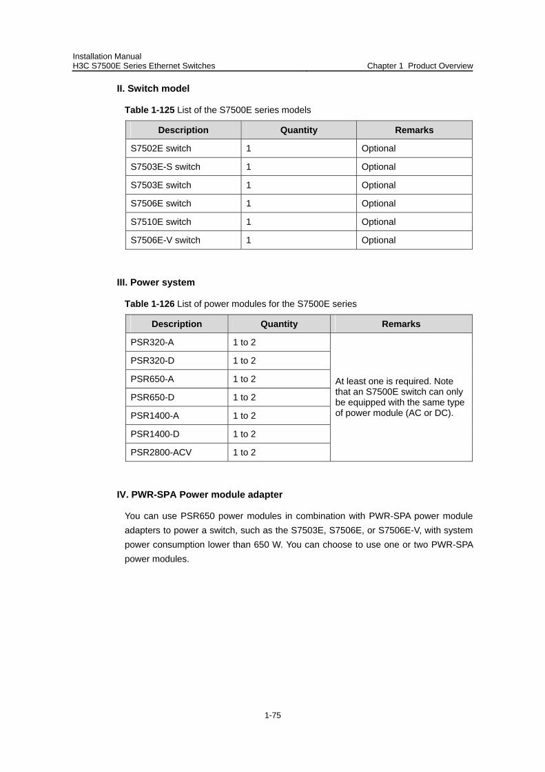
Installation Manual H3C S7500E Series Ethernet Switches Chapter 1 Product Overview
1-75
II. Switch model
Table 1-125 List of the S7500E series models
Description Quantity Remarks
S7502E switch 1 Optional
S7503E-S switch 1 Optional
S7503E switch 1 Optional
S7506E switch 1 Optional
S7510E switch 1 Optional
S7506E-V switch 1 Optional
III. Power system
Table 1-126 List of power modules for the S7500E series
Description Quantity Remarks
PSR320-A 1 to 2
PSR320-D 1 to 2
PSR650-A 1 to 2
PSR650-D 1 to 2
PSR1400-A 1 to 2
PSR1400-D 1 to 2
PSR2800-ACV 1 to 2
At least one is required. Note that an S7500E switch can only be equipped with the same type of power module (AC or DC).
IV. PWR-SPA Power module adapter
You can use PSR650 power modules in combination with PWR-SPA power module adapters to power a switch, such as the S7503E, S7506E, or S7506E-V, with system power consumption lower than 650 W. You can choose to use one or two PWR-SPA power modules.
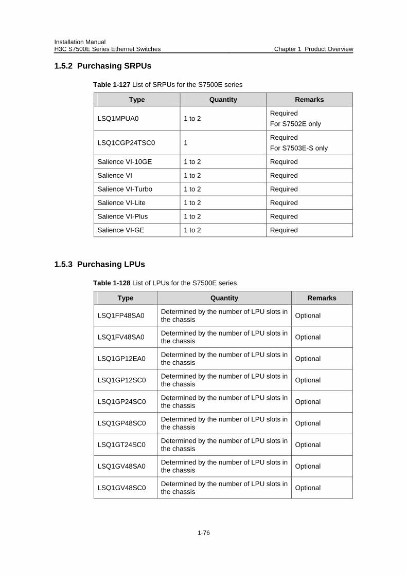
Installation Manual H3C S7500E Series Ethernet Switches Chapter 1 Product Overview
1-76
1.5.2 Purchasing SRPUs
Table 1-127 List of SRPUs for the S7500E series
Type Quantity Remarks
LSQ1MPUA0 1 to 2 Required For S7502E only
LSQ1CGP24TSC0 1 Required For S7503E-S only
Salience VI-10GE 1 to 2 Required
Salience VI 1 to 2 Required
Salience VI-Turbo 1 to 2 Required
Salience VI-Lite 1 to 2 Required
Salience VI-Plus 1 to 2 Required
Salience VI-GE 1 to 2 Required
1.5.3 Purchasing LPUs
Table 1-128 List of LPUs for the S7500E series
Type Quantity Remarks
LSQ1FP48SA0 Determined by the number of LPU slots in the chassis Optional
LSQ1FV48SA0 Determined by the number of LPU slots in the chassis Optional
LSQ1GP12EA0 Determined by the number of LPU slots in the chassis Optional
LSQ1GP12SC0 Determined by the number of LPU slots in the chassis Optional
LSQ1GP24SC0 Determined by the number of LPU slots in the chassis Optional
LSQ1GP48SC0 Determined by the number of LPU slots in the chassis Optional
LSQ1GT24SC0 Determined by the number of LPU slots in the chassis Optional
LSQ1GV48SA0 Determined by the number of LPU slots in the chassis Optional
LSQ1GV48SC0 Determined by the number of LPU slots in the chassis Optional
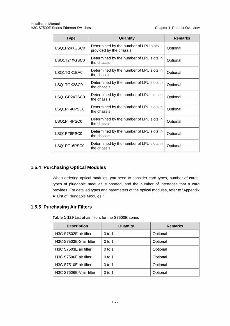
Installation Manual H3C S7500E Series Ethernet Switches Chapter 1 Product Overview
1-77
Type Quantity Remarks
LSQ1P24XGSC0 Determined by the number of LPU slots provided by the chassis Optional
LSQ1T24XGSC0 Determined by the number of LPU slots in the chassis Optional
LSQ1TGX1EA0 Determined by the number of LPU slots in the chassis Optional
LSQ1TGX2SC0 Determined by the number of LPU slots in the chassis Optional
LSQ1GP24TSC0 Determined by the number of LPU slots in the chassis Optional
LSQ1PT40PSC0 Determined by the number of LPU slots in the chassis Optional
LSQ1PT4PSC0 Determined by the number of LPU slots in the chassis Optional
LSQ1PT8PSC0 Determined by the number of LPU slots in the chassis Optional
LSQ1PT16PSC0 Determined by the number of LPU slots in the chassis Optional
1.5.4 Purchasing Optical Modules
When ordering optical modules, you need to consider card types, number of cards, types of pluggable modules supported, and the number of interfaces that a card provides. For detailed types and parameters of the optical modules, refer to “Appendix A List of Pluggable Modules.”
1.5.5 Purchasing Air Filters
Table 1-129 List of air filters for the S7500E series
Description Quantity Remarks
H3C S7502E air filter 0 to 1 Optional
H3C S7503E-S air filter 0 to 1 Optional
H3C S7503E air filter 0 to 1 Optional
H3C S7506E air filter 0 to 1 Optional
H3C S7510E air filter 0 to 1 Optional
H3C S7506E-V air filter 0 to 1 Optional
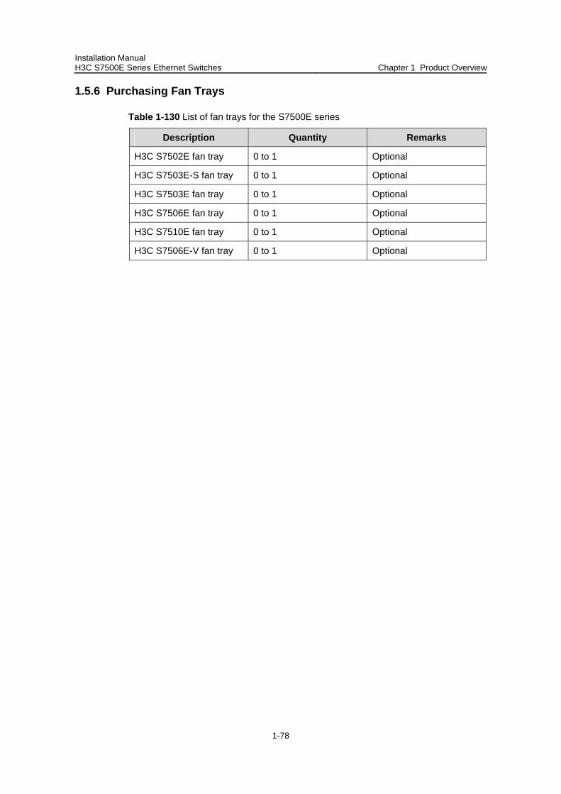
Installation Manual H3C S7500E Series Ethernet Switches Chapter 1 Product Overview
1-78
1.5.6 Purchasing Fan Trays
Table 1-130 List of fan trays for the S7500E series
Description Quantity Remarks
H3C S7502E fan tray 0 to 1 Optional
H3C S7503E-S fan tray 0 to 1 Optional
H3C S7503E fan tray 0 to 1 Optional
H3C S7506E fan tray 0 to 1 Optional
H3C S7510E fan tray 0 to 1 Optional
H3C S7506E-V fan tray 0 to 1 Optional
Installation Manual H3C S7500E Series Ethernet Switches Tables of Contents
i
Table of Contents
Chapter 2 Installation Preparations............................................................................................. 2-1 2.1 Safety Instructions ............................................................................................................. 2-1
2.1.1 General Instructions ................................................................................................ 2-1 2.1.2 Electrical Safety....................................................................................................... 2-1 2.1.3 Handling Safety ....................................................................................................... 2-1 2.1.4 Anti-static Safety ..................................................................................................... 2-2 2.1.5 Laser Safety ............................................................................................................ 2-3
2.2 Examining Installation Site................................................................................................. 2-3 2.2.1 Temperature/Humidity Requirements ..................................................................... 2-3 2.2.2 Cleanness Requirements........................................................................................ 2-4 2.2.3 Anti-static Requirements ......................................................................................... 2-4 2.2.4 Grounding Requirements ........................................................................................ 2-5 2.2.5 Power Supply Requirements................................................................................... 2-5
2.3 Installation Planning........................................................................................................... 2-5 2.3.1 Installation Space Requirement .............................................................................. 2-5 2.3.2 Rack-Mounting Requirements................................................................................. 2-5
2.4 Installation Tools ................................................................................................................ 2-6
Installation Manual H3C S7500E Series Ethernet Switches Chapter 2 Installation Preparations
2-1
Chapter 2 Installation Preparations
2.1 Safety Instructions
To avoid damage to human body and devices, please read the following safety recommendations carefully before installing the S7500E series. The recommendations do not cover every possible hazardous condition.
2.1.1 General Instructions
Turn OFF all the powers and remove all the power cables before opening the chassis.
Keep the chassis clean and dust-free. Keep the chassis and installation tools away from walk areas. Do not wear loose clothing, jewelry (including ring and necklace, and so on) or any
other things that could get caught in the chassis when you install and maintain the switch.
2.1.2 Electrical Safety
Look carefully for possible hazards in your work area, such as ungrounded power extension cables, missing safety grounds, and moist floors.
Locate the emergency power-off switch in the room before installation. Shut the power off at once in case accident occurs.
Unplug all the power cables and external cables before moving the chassis. Better not maintain the equipment alone when it has been powered by electricity. Never assume that power is disconnected from a circuit. Always check. Do not place the switch on a moist area and avoid liquid flowing into the switch.
2.1.3 Handling Safety
The S7500E series are rather big and heavy, so follow the recommendations below when moving them.
Turn off all the powers and remove all the power cables before opening the chassis.
Do not move the switch alone. Work with another person. Move the switch slowly and stably. Never move suddenly or twist your body. Move the switch at stable and consistent paces with your peer. Keep balance of
your body.
Installation Manual H3C S7500E Series Ethernet Switches Chapter 2 Installation Preparations
2-2
Caution:
Hold the handles on both sides of the chassis, instead of power handles or the vent of the chassis when moving the switch. Since the power handle or the vent is not designed to bear the weight of the entire chassis, the switch may get damaged or even your body may get hurt if you hold these parts to move the switch.
2.1.4 Anti-static Safety
To prevent the electric component from being damaged by the electrostatic discharge (ESD), take ESD measures for the area where the switch is located and note the points below:
Always wear an ESD-preventive wrist strap when installing the parts, especially the electric printed circuit boards, of the switch.
Take the edge of the circuit board. Do not touch the components or the electric printed circuit.
Take the following steps to use the ESD-preventive wrist strap.
Step 1: Wear the ESD-preventive wrist strap.
Step 2: Strain and tighten the strap, and ensure that it makes good contact with your skin.
Step 3: Insert the grounding terminal of the ESD-preventive wrist strap into the jack on the switch chassis or attach it to the grounding screw of the chassis with an alligator clip.
Step 4: Make sure the ESD-preventive wrist strap is well grounded.
Note:
An ESD-preventive wrist strap is shipped with the S7500E series. There is a jack for the ESD-preventive wrist strap on the chassis of the S7500E series.
Caution:
For safety case, check the resistance of the ESD-preventive wrist strap. The resistance between human body and the ground should be 1 to 10M ohm.
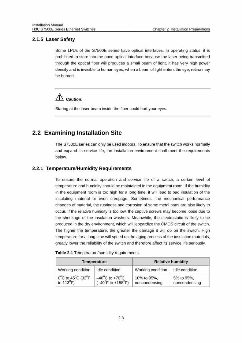
Installation Manual H3C S7500E Series Ethernet Switches Chapter 2 Installation Preparations
2-3
2.1.5 Laser Safety
Some LPUs of the S7500E series have optical interfaces. In operating status, it is prohibited to stare into the open optical interface because the laser being transmitted through the optical fiber will produces a small beam of light, it has very high power density and is invisible to human eyes, when a beam of light enters the eye, retina may be burned.
Caution:
Staring at the laser beam inside the fiber could hurt your eyes.
2.2 Examining Installation Site
The S7500E series can only be used indoors. To ensure that the switch works normally and expand its service life, the installation environment shall meet the requirements below.
2.2.1 Temperature/Humidity Requirements
To ensure the normal operation and service life of a switch, a certain level of temperature and humidity should be maintained in the equipment room. If the humidity in the equipment room is too high for a long time, it will lead to bad insulation of the insulating material or even creepage. Sometimes, the mechanical performance changes of material, the rustiness and corrosion of some metal parts are also likely to occur. If the relative humidity is too low, the captive screws may become loose due to the shrinkage of the insulation washers. Meanwhile, the electrostatic is likely to be produced in the dry environment, which will jeopardize the CMOS circuit of the switch. The higher the temperature, the greater the damage it will do on the switch. High temperature for a long time will speed up the aging process of the insulation materials, greatly lower the reliability of the switch and therefore affect its service life seriously.
Table 2-1 Temperature/humidity requirements
Temperature Relative humidity
Working condition Idle condition Working condition Idle condition
00C to 450C (320F to 1130F)
–400C to +700C (–400F to +1580F)
10% to 95%, noncondensing
5% to 95%, noncondensing
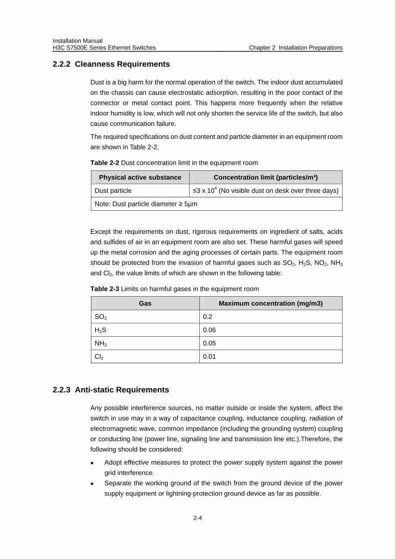
Installation Manual H3C S7500E Series Ethernet Switches Chapter 2 Installation Preparations
2-4
2.2.2 Cleanness Requirements
Dust is a big harm for the normal operation of the switch. The indoor dust accumulated on the chassis can cause electrostatic adsorption, resulting in the poor contact of the connector or metal contact point. This happens more frequently when the relative indoor humidity is low, which will not only shorten the service life of the switch, but also cause communication failure.
The required specifications on dust content and particle diameter in an equipment room are shown in Table 2-2.
Table 2-2 Dust concentration limit in the equipment room
Physical active substance Concentration limit (particles/m³)
Dust particle ≤3 x 10⁴ (No visible dust on desk over three days)
Note: Dust particle diameter ≥ 5µm
Except the requirements on dust, rigorous requirements on ingredient of salts, acids and sulfides of air in an equipment room are also set. These harmful gases will speed up the metal corrosion and the aging processes of certain parts. The equipment room should be protected from the invasion of harmful gases such as SO2, H2S, NO2, NH3 and Cl2, the value limits of which are shown in the following table:
Table 2-3 Limits on harmful gases in the equipment room
Gas Maximum concentration (mg/m3)
SO2 0.2
H2S 0.06
NH3 0.05
Cl2 0.01
2.2.3 Anti-static Requirements
Any possible interference sources, no matter outside or inside the system, affect the switch in use may in a way of capacitance coupling, inductance coupling, radiation of electromagnetic wave, common impedance (including the grounding system) coupling or conducting line (power line, signaling line and transmission line etc.).Therefore, the following should be considered:
Adopt effective measures to protect the power supply system against the power grid interference.
Separate the working ground of the switch from the ground device of the power supply equipment or lightning-protection ground device as far as possible.
Installation Manual H3C S7500E Series Ethernet Switches Chapter 2 Installation Preparations
2-5
Keep the switch far away from the radio launcher, radar launcher, and high-frequency devices working in high currents.
If necessary, adopt electromagnetic shield.
2.2.4 Grounding Requirements
A good grounding system is the basis for a switch to work stably and reliably and the important guarantee of lightning protection, anti-interference and ESD. A user should provide good grounding system for the switch and the grounding resistance should be less than 1.5 ohm.
2.2.5 Power Supply Requirements
For the power supply requirements, refer to section 1.2.3 “Power Supply System” in Chapter 1 “Product Overview”.
2.3 Installation Planning
Since the S7500E series are a kind of complex equipment, it is necessary to make a good plan and arrangement concerning installation position, networking mode, power supply and cabling before installation.
2.3.1 Installation Space Requirement
For better heat dissipation and equipment maintenance, it is recommended that the front and back of the switch should be at least one meter away from walls or other devices, and that the left and right of the switch should be at least 0.8 meters away from walls. If a rack is to be installed, the headroom should be 3 meters at least.
If the above-mentioned requirements are not satisfied, it will be very inconvenient to install a rack or install air filters on the switch.
2.3.2 Rack-Mounting Requirements
Before rack-mounting a switch, make sure the rack meets the following requirements:
Better mount a switch in an open rack. However, if you mount a switch in a closed rack, make sure of good heat dissipation system.
Make sure the rack stands steadily enough to well support the switch and accessories.
Make sure that the switch fits the rack size. Leave some spaces beside the left and right panels of the switch for chassis heat dissipation.
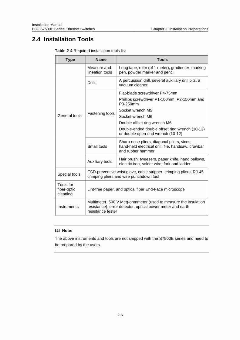
Installation Manual H3C S7500E Series Ethernet Switches Chapter 2 Installation Preparations
2-6
2.4 Installation Tools
Table 2-4 Required installation tools list
Type Name Tools
Measure and lineation tools
Long tape, ruler (of 1 meter), gradienter, marking pen, powder marker and pencil
Drills A percussion drill, several auxiliary drill bits, a vacuum cleaner
Fastening tools
Flat-blade screwdriver P4-75mm Phillips screwdriver P1-100mm, P2-150mm and P3-250mm Socket wrench M5 Socket wrench M6 Double offset ring wrench M6 Double-ended double offset ring wrench (10-12) or double open-end wrench (10-12)
Small tools Sharp-nose pliers, diagonal pliers, vices, hand-held electrical drill, file, handsaw, crowbar and rubber hammer
General tools
Auxiliary tools Hair brush, tweezers, paper knife, hand bellows, electric iron, solder wire, fork and ladder
Special tools ESD-preventive wrist glove, cable stripper, crimping pliers, RJ-45 crimping pliers and wire punchdown tool
Tools for fiber-optic cleaning
Lint-free paper, and optical fiber End-Face microscope
Instruments Multimeter, 500 V Meg-ohmmeter (used to measure the insulation resistance), error detector, optical power meter and earth resistance tester
Note:
The above instruments and tools are not shipped with the S7500E series and need to be prepared by the users.
Installation Manual H3C S7500E Series Ethernet Switches Tables of Contents
i
Table of Contents
Chapter 3 Hardware Installation .................................................................................................. 3-1 3.1 Confirming Installation Preparations.................................................................................. 3-1 3.2 Installation Flowchart ......................................................................................................... 3-1 3.3 Mounting a Switch to the Designated Position .................................................................. 3-2
3.3.1 Mounting a Switch into a Cabinet............................................................................ 3-2 3.3.2 Mounting a Switch on a Workbench........................................................................ 3-3
3.4 Connecting the Grounding Cable ...................................................................................... 3-3 3.5 Installing Switch Modules .................................................................................................. 3-6 3.6 Connecting the Power Cable ............................................................................................. 3-6
3.6.1 Connecting the AC Power Cable ............................................................................ 3-6 3.6.2 Connecting the DC Power Cables .......................................................................... 3-8 3.6.3 Connecting PoE Power Cables............................................................................. 3-10
3.7 Connecting Interface Cables ........................................................................................... 3-12 3.7.1 Connecting the Console Cable ............................................................................. 3-12 3.7.2 Connecting the AUX Cable (Optional) .................................................................. 3-13 3.7.3 Connecting the COM Cable .................................................................................. 3-14 3.7.4 Connecting Category-5 Cables ............................................................................. 3-14 3.7.5 Connecting Fibers ................................................................................................. 3-16
3.8 Cabling............................................................................................................................. 3-17 3.8.1 Workbench-Mounted Switch ................................................................................. 3-17 3.8.2 Rack-Mounted Switch ........................................................................................... 3-17 3.8.3 General Cabling Requirements............................................................................. 3-18
3.9 Cable Binding................................................................................................................... 3-18 3.9.1 Correct Use of Labels ........................................................................................... 3-18 3.9.2 Precautions for Cable Binding............................................................................... 3-19
3.10 Checking the Installation................................................................................................ 3-22
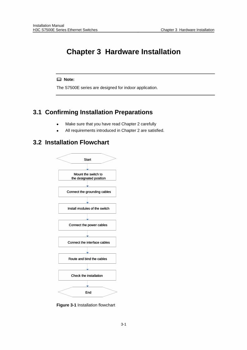
Installation Manual H3C S7500E Series Ethernet Switches Chapter 3 Hardware Installation
3-1
Chapter 3 Hardware Installation
Note:
The S7500E series are designed for indoor application.
3.1 Confirming Installation Preparations
Make sure that you have read Chapter 2 carefully All requirements introduced in Chapter 2 are satisfied.
3.2 Installation Flowchart
Connect the power cables
Mount the switch to the designated position
Install modules of the switch
Connect the interface cables
Route and bind the cables
Check the installation
Start
End
Connect the grounding cables
Connect the power cables
Mount the switch to the designated position
Install modules of the switch
Connect the interface cables
Route and bind the cables
Check the installation
Start
End
Connect the grounding cables
Figure 3-1 Installation flowchart
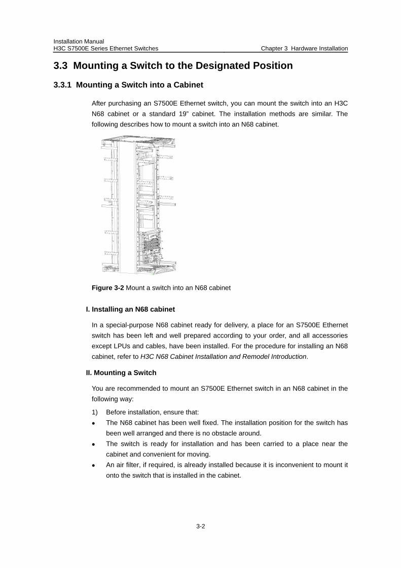
Installation Manual H3C S7500E Series Ethernet Switches Chapter 3 Hardware Installation
3-2
3.3 Mounting a Switch to the Designated Position
3.3.1 Mounting a Switch into a Cabinet
After purchasing an S7500E Ethernet switch, you can mount the switch into an H3C N68 cabinet or a standard 19” cabinet. The installation methods are similar. The following describes how to mount a switch into an N68 cabinet.
Figure 3-2 Mount a switch into an N68 cabinet
I. Installing an N68 cabinet
In a special-purpose N68 cabinet ready for delivery, a place for an S7500E Ethernet switch has been left and well prepared according to your order, and all accessories except LPUs and cables, have been installed. For the procedure for installing an N68 cabinet, refer to H3C N68 Cabinet Installation and Remodel Introduction.
II. Mounting a Switch
You are recommended to mount an S7500E Ethernet switch in an N68 cabinet in the following way:
1) Before installation, ensure that: The N68 cabinet has been well fixed. The installation position for the switch has
been well arranged and there is no obstacle around. The switch is ready for installation and has been carried to a place near the
cabinet and convenient for moving. An air filter, if required, is already installed because it is inconvenient to mount it
onto the switch that is installed in the cabinet.
Installation Manual H3C S7500E Series Ethernet Switches Chapter 3 Hardware Installation
3-3
2) Mount weight-bearing guide rails on the N68 cabinet based on the installation position of the switch. (Two types of weight-bearing guide rails are available. One is small guide rails and applicable to the S7502E and S7503E-S. The other is large guide rails and applicable to the S7500E series other than the S7502E and S7503E-S.)
3) Mount the cable rack and mounting ears on the switch. 4) Together with another person, carry the switch to the front of the cabinet slowly. 5) Lift the switch a little above the weight-bearing guide rails and put it on the guide
rails and adjust its position. 6) Fix the mounting ears to the square-hole brackets of the N68 cabinet with
fastening screws.
3.3.2 Mounting a Switch on a Workbench
1) Before installation, make sure that: The workbench is firm enough to hold the switch and cables. There are no obstacles around the workbench. The switch is ready for installation and has been carried near to the workbench.
2) Together with another person, carry the switch to front of the workbench slowly. 3) Lift the switch a little above the workbench and put the switch on it.
3.4 Connecting the Grounding Cable
Warning:
Correct connection of the protection grounding cable of the switch ensures the lightning protection and anti-interference performance of the switch. Thus, you must connect the grounding cable properly when installing and using a switch.
I. Common grounding environment
1) Remove the grounding screw from the lower right part of the rear panel of the switch chassis.
2) Set the grounding cable connector provided together with the switch around the grounding screw.
3) Fasten the grounding screw in the hole on the chassis. 4) Connect the other end of the grounding cable to the grounding strip of the switch.
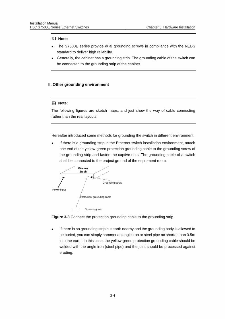
Installation Manual H3C S7500E Series Ethernet Switches Chapter 3 Hardware Installation
3-4
Note:
The S7500E series provide dual grounding screws in compliance with the NEBS standard to deliver high reliability.
Generally, the cabinet has a grounding strip. The grounding cable of the switch can be connected to the grounding strip of the cabinet.
II. Other grounding environment
Note:
The following figures are sketch maps, and just show the way of cable connecting rather than the real layouts.
Hereafter introduced some methods for grounding the switch in different environment.
If there is a grounding strip in the Ethernet switch installation environment, attach one end of the yellow-green protection grounding cable to the grounding screw of the grounding strip and fasten the captive nuts. The grounding cable of a switch shall be connected to the project ground of the equipment room.
Power input
Ethernet Switch
Grounding strip
Protection grounding cable
Grounding screw
Ethernet Switch
Ethernet Switch
Figure 3-3 Connect the protection grounding cable to the grounding strip
If there is no grounding strip but earth nearby and the grounding body is allowed to be buried, you can simply hammer an angle iron or steel pipe no shorter than 0.5m into the earth. In this case, the yellow-green protection grounding cable should be welded with the angle iron (steel pipe) and the joint should be processed against eroding.
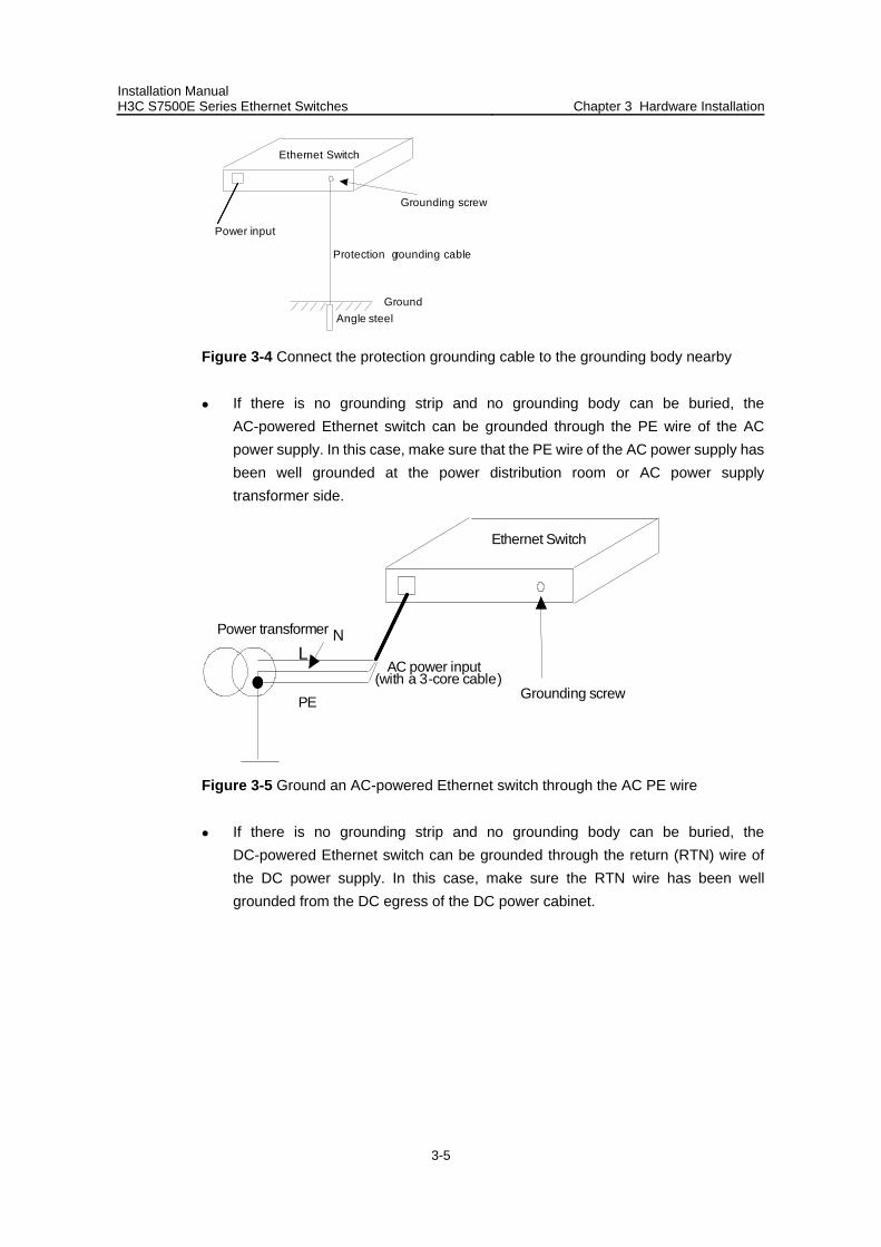
Installation Manual H3C S7500E Series Ethernet Switches Chapter 3 Hardware Installation
3-5
Power input
Ethernet Switch
Grounding screw
Angle steelGround
Protection grounding cable
Figure 3-4 Connect the protection grounding cable to the grounding body nearby
If there is no grounding strip and no grounding body can be buried, the AC-powered Ethernet switch can be grounded through the PE wire of the AC power supply. In this case, make sure that the PE wire of the AC power supply has been well grounded at the power distribution room or AC power supply transformer side.
AC power input
Ethernet Switch
Grounding screw
LN
PE
Power transformer
(with a 3-core cable)
Figure 3-5 Ground an AC-powered Ethernet switch through the AC PE wire
If there is no grounding strip and no grounding body can be buried, the DC-powered Ethernet switch can be grounded through the return (RTN) wire of the DC power supply. In this case, make sure the RTN wire has been well grounded from the DC egress of the DC power cabinet.
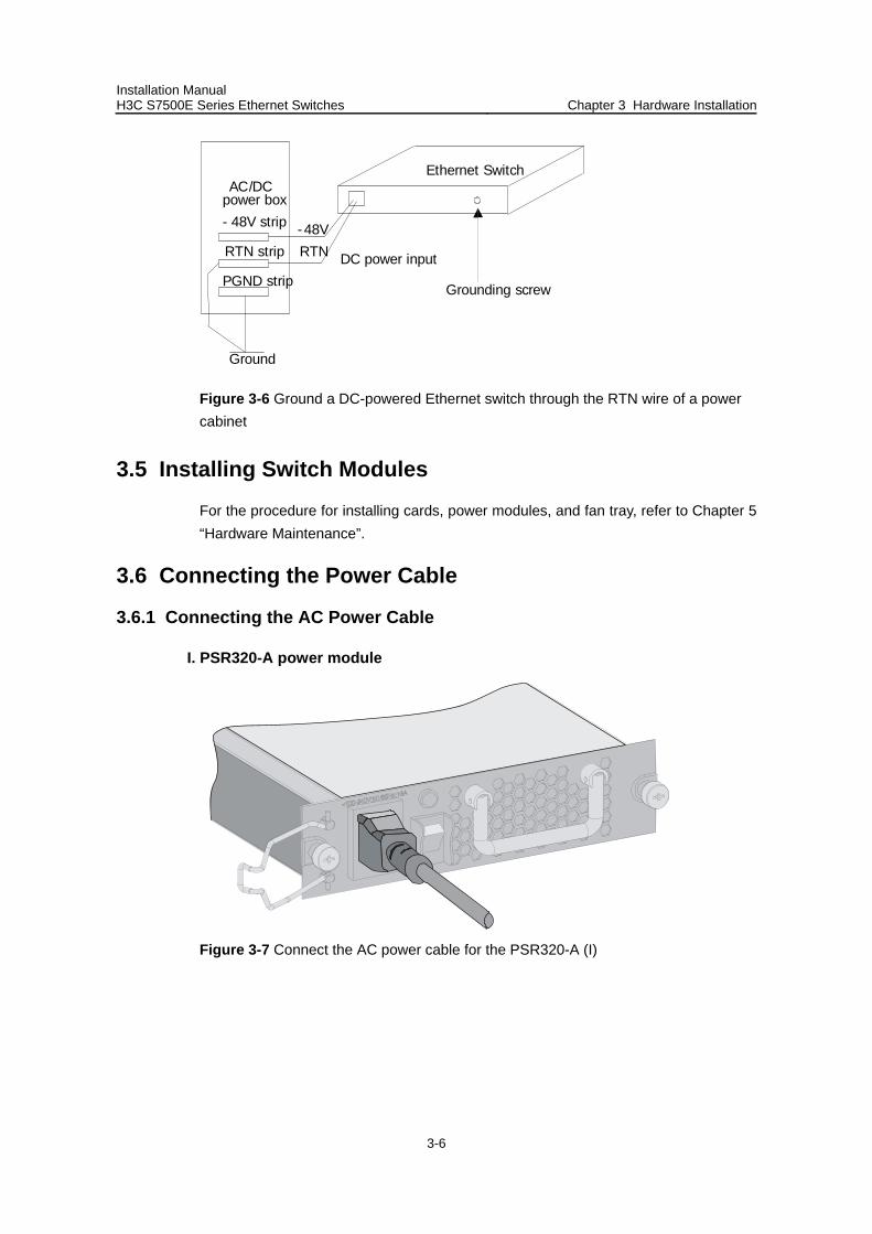
Installation Manual H3C S7500E Series Ethernet Switches Chapter 3 Hardware Installation
3-6
DC power input
Ethernet Switch
RTN-48V
AC/DCpower box- 48V strip
RTN strip
PGND strip
Ground
Grounding screw
Figure 3-6 Ground a DC-powered Ethernet switch through the RTN wire of a power cabinet
3.5 Installing Switch Modules
For the procedure for installing cards, power modules, and fan tray, refer to Chapter 5 “Hardware Maintenance”.
3.6 Connecting the Power Cable
3.6.1 Connecting the AC Power Cable
I. PSR320-A power module
Figure 3-7 Connect the AC power cable for the PSR320-A (I)
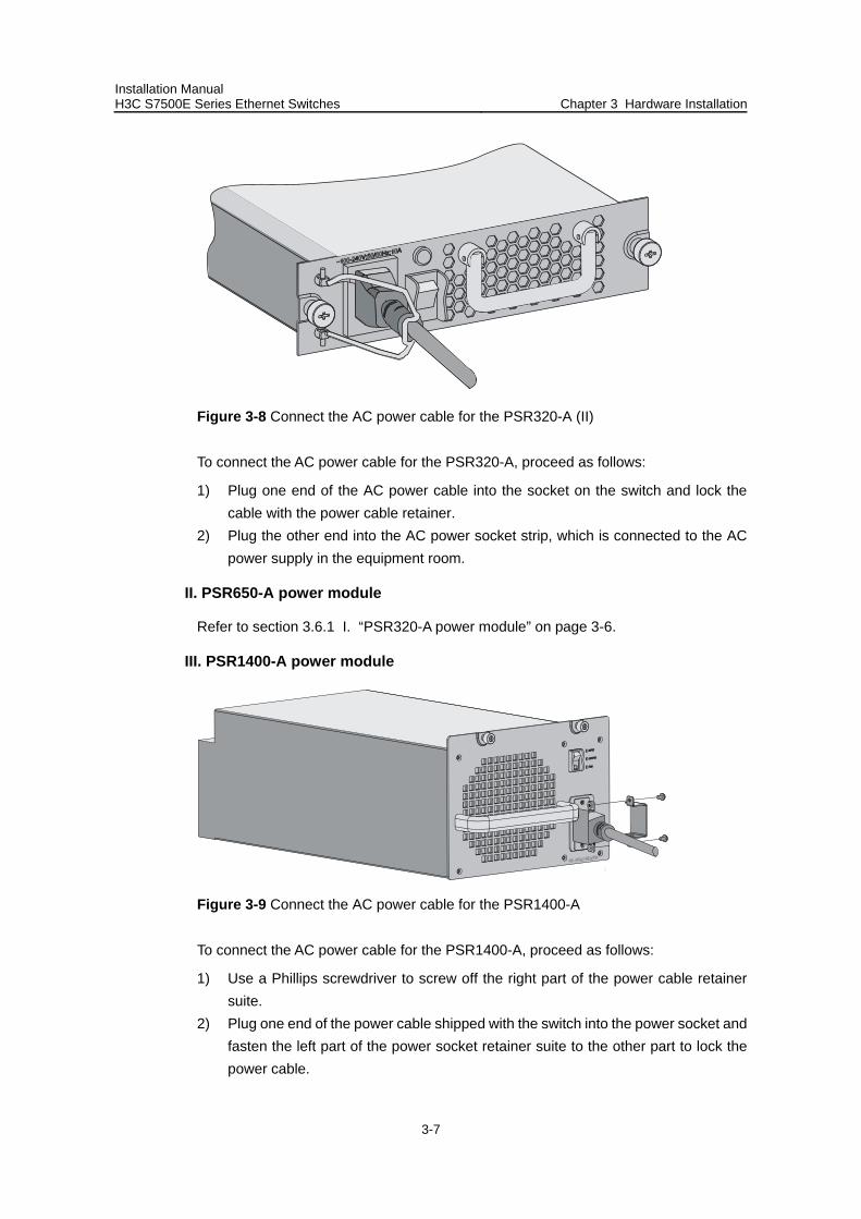
Installation Manual H3C S7500E Series Ethernet Switches Chapter 3 Hardware Installation
3-7
Figure 3-8 Connect the AC power cable for the PSR320-A (II)
To connect the AC power cable for the PSR320-A, proceed as follows:
1) Plug one end of the AC power cable into the socket on the switch and lock the cable with the power cable retainer.
2) Plug the other end into the AC power socket strip, which is connected to the AC power supply in the equipment room.
II. PSR650-A power module
Refer to section 3.6.1 I. “PSR320-A power module” on page 3-6.
III. PSR1400-A power module
Figure 3-9 Connect the AC power cable for the PSR1400-A
To connect the AC power cable for the PSR1400-A, proceed as follows:
1) Use a Phillips screwdriver to screw off the right part of the power cable retainer suite.
2) Plug one end of the power cable shipped with the switch into the power socket and fasten the left part of the power socket retainer suite to the other part to lock the power cable.
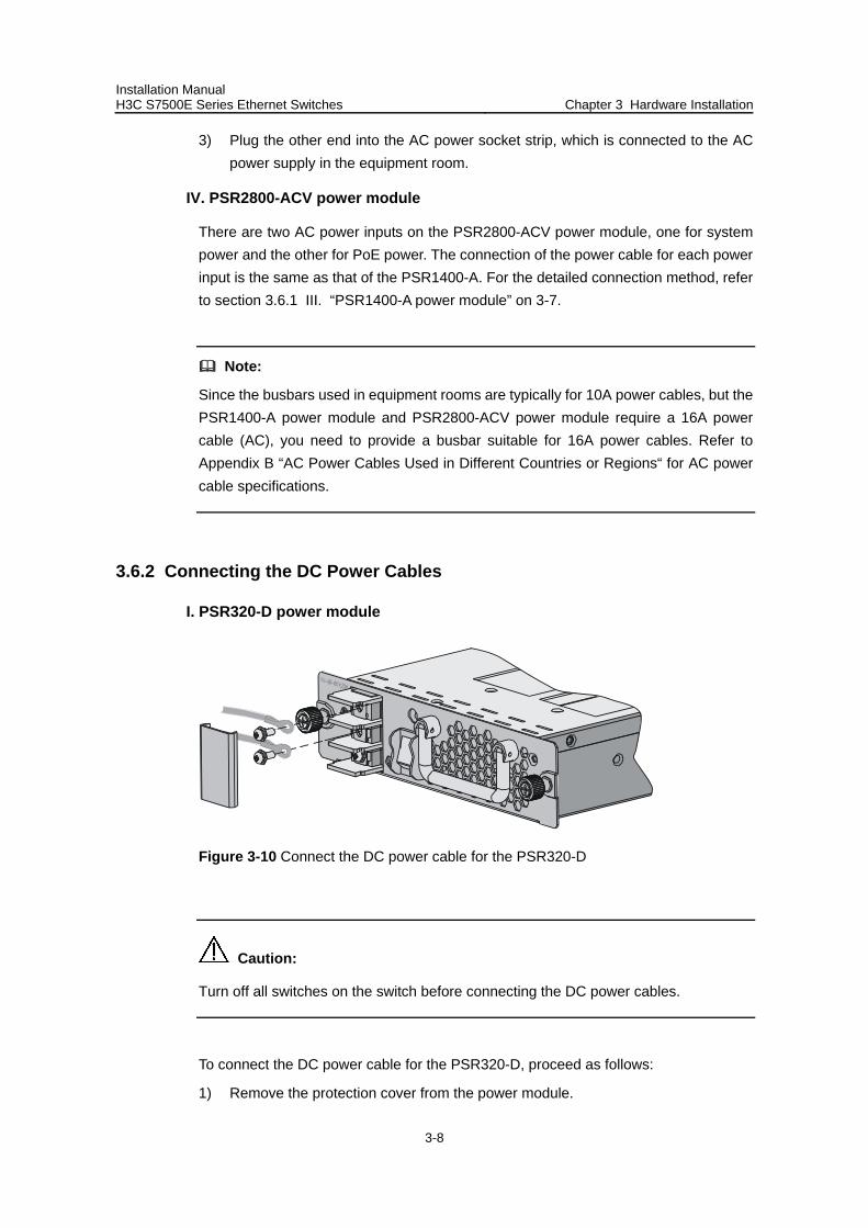
Installation Manual H3C S7500E Series Ethernet Switches Chapter 3 Hardware Installation
3-8
3) Plug the other end into the AC power socket strip, which is connected to the AC power supply in the equipment room.
IV. PSR2800-ACV power module
There are two AC power inputs on the PSR2800-ACV power module, one for system power and the other for PoE power. The connection of the power cable for each power input is the same as that of the PSR1400-A. For the detailed connection method, refer to section 3.6.1 III. “PSR1400-A power module” on 3-7.
Note:
Since the busbars used in equipment rooms are typically for 10A power cables, but the PSR1400-A power module and PSR2800-ACV power module require a 16A power cable (AC), you need to provide a busbar suitable for 16A power cables. Refer to Appendix B “AC Power Cables Used in Different Countries or Regions“ for AC power cable specifications.
3.6.2 Connecting the DC Power Cables
I. PSR320-D power module
Figure 3-10 Connect the DC power cable for the PSR320-D
Caution:
Turn off all switches on the switch before connecting the DC power cables.
To connect the DC power cable for the PSR320-D, proceed as follows:
1) Remove the protection cover from the power module.
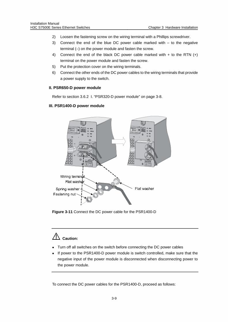
Installation Manual H3C S7500E Series Ethernet Switches Chapter 3 Hardware Installation
3-9
2) Loosen the fastening screw on the wiring terminal with a Phillips screwdriver. 3) Connect the end of the blue DC power cable marked with – to the negative
terminal (–) on the power module and fasten the screw. 4) Connect the end of the black DC power cable marked with + to the RTN (+)
terminal on the power module and fasten the screw. 5) Put the protection cover on the wiring terminals. 6) Connect the other ends of the DC power cables to the wiring terminals that provide
a power supply to the switch.
II. PSR650-D power module
Refer to section 3.6.2 I. “PSR320-D power module” on page 3-8.
III. PSR1400-D power module
Figure 3-11 Connect the DC power cable for the PSR1400-D
Caution:
Turn off all switches on the switch before connecting the DC power cables If power to the PSR1400-D power module is switch controlled, make sure that the
negative input of the power module is disconnected when disconnecting power to the power module.
To connect the DC power cables for the PSR1400-D, proceed as follows:
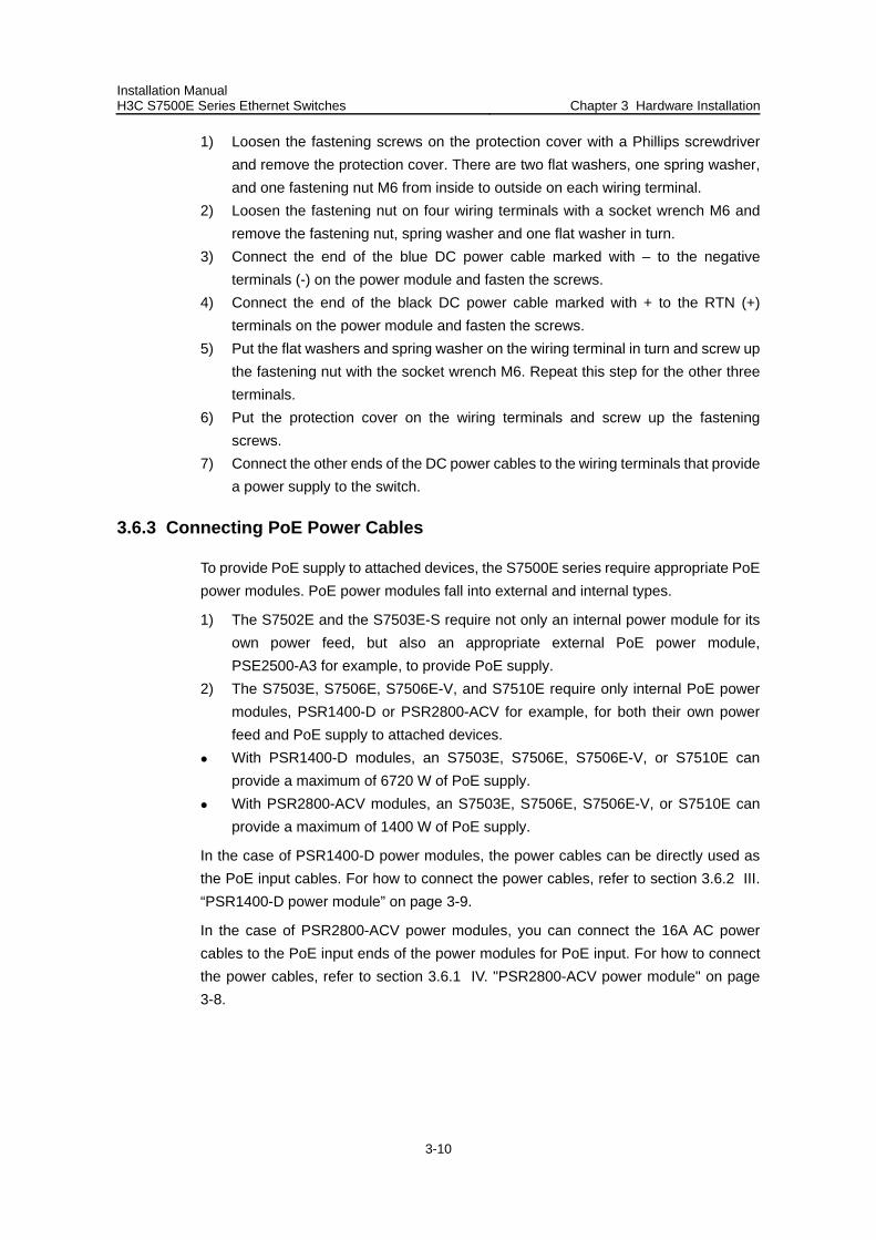
Installation Manual H3C S7500E Series Ethernet Switches Chapter 3 Hardware Installation
3-10
1) Loosen the fastening screws on the protection cover with a Phillips screwdriver and remove the protection cover. There are two flat washers, one spring washer, and one fastening nut M6 from inside to outside on each wiring terminal.
2) Loosen the fastening nut on four wiring terminals with a socket wrench M6 and remove the fastening nut, spring washer and one flat washer in turn.
3) Connect the end of the blue DC power cable marked with – to the negative terminals (-) on the power module and fasten the screws.
4) Connect the end of the black DC power cable marked with + to the RTN (+) terminals on the power module and fasten the screws.
5) Put the flat washers and spring washer on the wiring terminal in turn and screw up the fastening nut with the socket wrench M6. Repeat this step for the other three terminals.
6) Put the protection cover on the wiring terminals and screw up the fastening screws.
7) Connect the other ends of the DC power cables to the wiring terminals that provide a power supply to the switch.
3.6.3 Connecting PoE Power Cables
To provide PoE supply to attached devices, the S7500E series require appropriate PoE power modules. PoE power modules fall into external and internal types.
1) The S7502E and the S7503E-S require not only an internal power module for its own power feed, but also an appropriate external PoE power module, PSE2500-A3 for example, to provide PoE supply.
2) The S7503E, S7506E, S7506E-V, and S7510E require only internal PoE power modules, PSR1400-D or PSR2800-ACV for example, for both their own power feed and PoE supply to attached devices.
With PSR1400-D modules, an S7503E, S7506E, S7506E-V, or S7510E can provide a maximum of 6720 W of PoE supply.
With PSR2800-ACV modules, an S7503E, S7506E, S7506E-V, or S7510E can provide a maximum of 1400 W of PoE supply.
In the case of PSR1400-D power modules, the power cables can be directly used as the PoE input cables. For how to connect the power cables, refer to section 3.6.2 III. “PSR1400-D power module” on page 3-9.
In the case of PSR2800-ACV power modules, you can connect the 16A AC power cables to the PoE input ends of the power modules for PoE input. For how to connect the power cables, refer to section 3.6.1 IV. "PSR2800-ACV power module" on page 3-8.
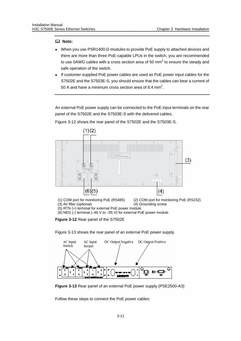
Installation Manual H3C S7500E Series Ethernet Switches Chapter 3 Hardware Installation
3-11
Note:
When you use PSR1400-D modules to provide PoE supply to attached devices and there are more than three PoE-capable LPUs in the switch, you are recommended to use 0AWG cables with a cross section area of 50 mm2 to ensure the steady and safe operation of the switch.
If customer-supplied PoE power cables are used as PoE power input cables for the S7502E and the S7503E-S, you should ensure that the cables can bear a current of 50 A and have a minimum cross section area of 8.4 mm2.
An external PoE power supply can be connected to the PoE input terminals on the rear panel of the S7502E and the S7503E-S with the delivered cables.
Figure 3-12 shows the rear panel of the S7502E and the S7503E-S.
(1) COM port for monitoring PoE (RS485) (2) COM port for monitoring PoE (RS232) (3) Air filter (optional) (4) Grounding screw (5) RTN (+) terminal for external PoE power module (6) NEG (-) terminal (–46 V to –55 V) for external PoE power module
Figure 3-12 Rear panel of the S7502E
Figure 3-13 shows the rear panel of an external PoE power supply.
Figure 3-13 Rear panel of an external PoE power supply (PSE2500-A3)
Follow these steps to connect the PoE power cables:
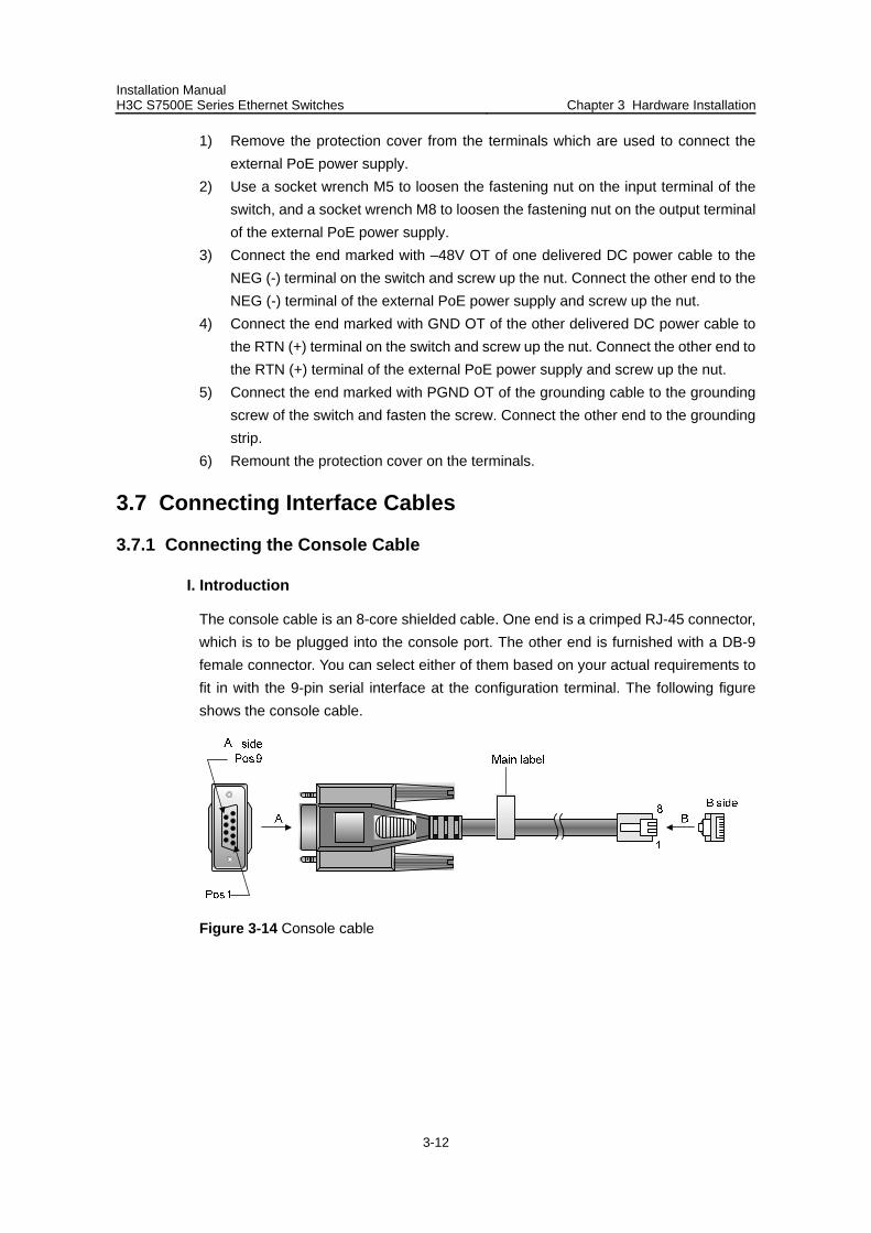
Installation Manual H3C S7500E Series Ethernet Switches Chapter 3 Hardware Installation
3-12
1) Remove the protection cover from the terminals which are used to connect the external PoE power supply.
2) Use a socket wrench M5 to loosen the fastening nut on the input terminal of the switch, and a socket wrench M8 to loosen the fastening nut on the output terminal of the external PoE power supply.
3) Connect the end marked with –48V OT of one delivered DC power cable to the NEG (-) terminal on the switch and screw up the nut. Connect the other end to the NEG (-) terminal of the external PoE power supply and screw up the nut.
4) Connect the end marked with GND OT of the other delivered DC power cable to the RTN (+) terminal on the switch and screw up the nut. Connect the other end to the RTN (+) terminal of the external PoE power supply and screw up the nut.
5) Connect the end marked with PGND OT of the grounding cable to the grounding screw of the switch and fasten the screw. Connect the other end to the grounding strip.
6) Remount the protection cover on the terminals.
3.7 Connecting Interface Cables
3.7.1 Connecting the Console Cable
I. Introduction
The console cable is an 8-core shielded cable. One end is a crimped RJ-45 connector, which is to be plugged into the console port. The other end is furnished with a DB-9 female connector. You can select either of them based on your actual requirements to fit in with the 9-pin serial interface at the configuration terminal. The following figure shows the console cable.
Figure 3-14 Console cable

Installation Manual H3C S7500E Series Ethernet Switches Chapter 3 Hardware Installation
3-13
Table 3-1 Console cable pinouts
Pin (RJ-45) Signal Pin (DB-9) Signal
1 RTS 8 CTS
2 DTR 6 DSR
3 TXD 2 RXD
4 SG 5 SG
5 SG 5 SG
6 RXD 3 TXD
7 DSR 4 DTR
8 CTS 7 RTS
II. Connecting the console cable
Take the following steps to connect the console cable, when configuring the switch on the terminal.
1) Plug the DB-9 female plug of the console cable to the serial port of the PC or the terminal where the switch is to be configured.
2) Connect the RJ-45 connector of the console cable to the console port of the switch.
3.7.2 Connecting the AUX Cable (Optional)
The AUX cable is used for the remote Modem dial-up configuration for the S7500E series.
I. Introduction
The AUX cable is an 8-core shielded cable. One end is an RJ-45 RS-232 connector, which can be plugged into the console port. The other end is furnished with a DB-9 connector, which can be plugged into the DB-9 socket on the Modem. The AUX cable is the same as the console cable. For details, see Figure 3-14 and Table 3-1.
II. Connection procedure
Follow these steps to connect the AUX cable:
1) Plug the RJ-45 connector of the AUX cable into the console port. 2) Plug the DB-9 connector of the AUX cable into the serial port of the analog
Modem.
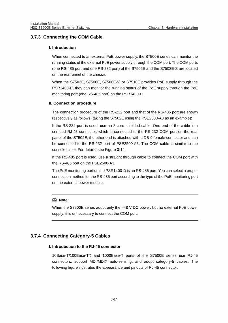
Installation Manual H3C S7500E Series Ethernet Switches Chapter 3 Hardware Installation
3-14
3.7.3 Connecting the COM Cable
I. Introduction
When connected to an external PoE power supply, the S7500E series can monitor the running status of the external PoE power supply through the COM port. The COM ports (one RS-485 port and one RS-232 port) of the S7502E and the S7503E-S are located on the rear panel of the chassis.
When the S7503E, S7506E, S7506E-V, or S7510E provides PoE supply through the PSR1400-D, they can monitor the running status of the PoE supply through the PoE monitoring port (one RS-485 port) on the PSR1400-D.
II. Connection procedure
The connection procedure of the RS-232 port and that of the RS-485 port are shown respectively as follows (taking the S7502E using the PSE2500-A3 as an example):
If the RS-232 port is used, use an 8-core shielded cable. One end of the cable is a crimped RJ-45 connector, which is connected to the RS-232 COM port on the rear panel of the S7502E; the other end is attached with a DB-9 female connector and can be connected to the RS-232 port of PSE2500-A3. The COM cable is similar to the console cable. For details, see Figure 3-14.
If the RS-485 port is used, use a straight through cable to connect the COM port with the RS-485 port on the PSE2500-A3.
The PoE monitoring port on the PSR1400-D is an RS-485 port. You can select a proper connection method for the RS-485 port according to the type of the PoE monitoring port on the external power module.
Note:
When the S7500E series adopt only the –48 V DC power, but no external PoE power supply, it is unnecessary to connect the COM port.
3.7.4 Connecting Category-5 Cables
I. Introduction to the RJ-45 connector
10Base-T/100Base-TX and 1000Base-T ports of the S7500E series use RJ-45 connectors, support MDI/MDIX auto-sensing, and adopt category-5 cables. The following figure illustrates the appearance and pinouts of RJ-45 connector.
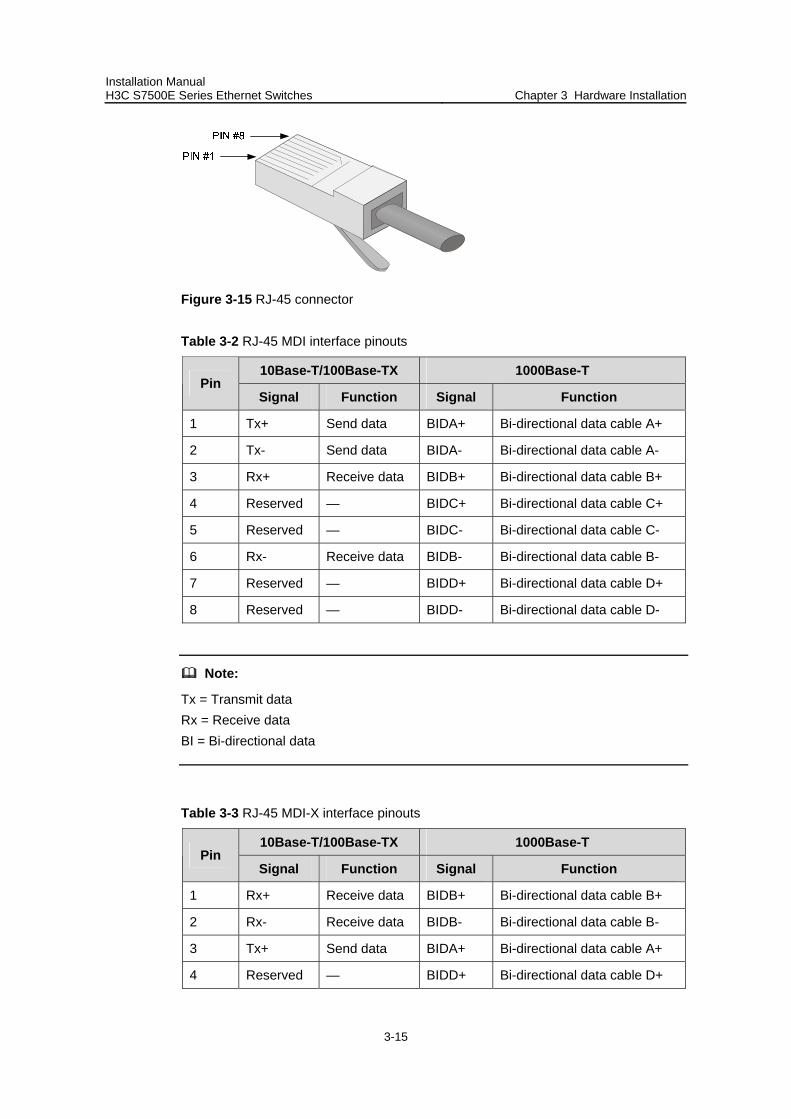
Installation Manual H3C S7500E Series Ethernet Switches Chapter 3 Hardware Installation
3-15
Figure 3-15 RJ-45 connector
Table 3-2 RJ-45 MDI interface pinouts
10Base-T/100Base-TX 1000Base-T Pin
Signal Function Signal Function
1 Tx+ Send data BIDA+ Bi-directional data cable A+
2 Tx- Send data BIDA- Bi-directional data cable A-
3 Rx+ Receive data BIDB+ Bi-directional data cable B+
4 Reserved — BIDC+ Bi-directional data cable C+
5 Reserved — BIDC- Bi-directional data cable C-
6 Rx- Receive data BIDB- Bi-directional data cable B-
7 Reserved — BIDD+ Bi-directional data cable D+
8 Reserved — BIDD- Bi-directional data cable D-
Note:
Tx = Transmit data Rx = Receive data BI = Bi-directional data
Table 3-3 RJ-45 MDI-X interface pinouts
10Base-T/100Base-TX 1000Base-T Pin
Signal Function Signal Function
1 Rx+ Receive data BIDB+ Bi-directional data cable B+
2 Rx- Receive data BIDB- Bi-directional data cable B-
3 Tx+ Send data BIDA+ Bi-directional data cable A+
4 Reserved — BIDD+ Bi-directional data cable D+
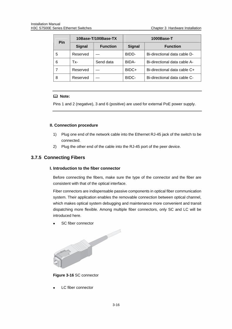
Installation Manual H3C S7500E Series Ethernet Switches Chapter 3 Hardware Installation
3-16
10Base-T/100Base-TX 1000Base-T Pin
Signal Function Signal Function
5 Reserved — BIDD- Bi-directional data cable D-
6 Tx- Send data BIDA- Bi-directional data cable A-
7 Reserved — BIDC+ Bi-directional data cable C+
8 Reserved — BIDC- Bi-directional data cable C-
Note:
Pins 1 and 2 (negative), 3 and 6 (positive) are used for external PoE power supply.
II. Connection procedure
1) Plug one end of the network cable into the Ethernet RJ-45 jack of the switch to be connected.
2) Plug the other end of the cable into the RJ-45 port of the peer device.
3.7.5 Connecting Fibers
I. Introduction to the fiber connector
Before connecting the fibers, make sure the type of the connector and the fiber are consistent with that of the optical interface.
Fiber connectors are indispensable passive components in optical fiber communication system. Their application enables the removable connection between optical channel, which makes optical system debugging and maintenance more convenient and transit dispatching more flexible. Among multiple fiber connectors, only SC and LC will be introduced here.
SC fiber connector
Figure 3-16 SC connector
LC fiber connector
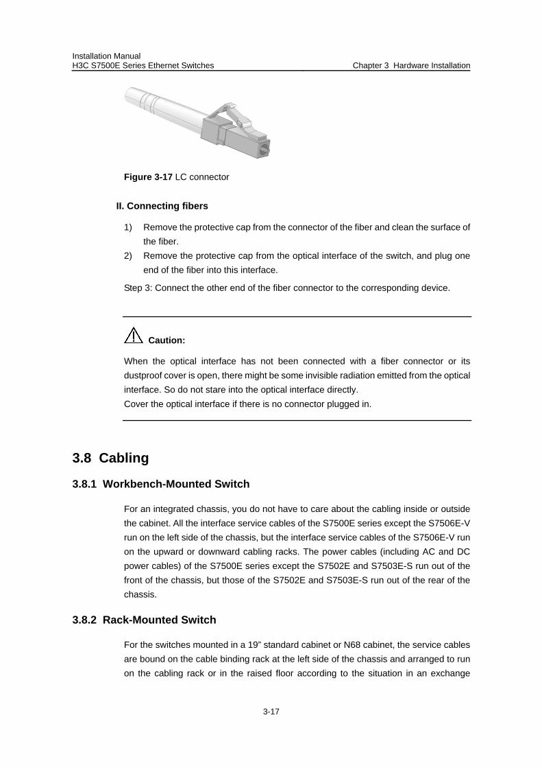
Installation Manual H3C S7500E Series Ethernet Switches Chapter 3 Hardware Installation
3-17
Figure 3-17 LC connector
II. Connecting fibers
1) Remove the protective cap from the connector of the fiber and clean the surface of the fiber.
2) Remove the protective cap from the optical interface of the switch, and plug one end of the fiber into this interface.
Step 3: Connect the other end of the fiber connector to the corresponding device.
Caution:
When the optical interface has not been connected with a fiber connector or its dustproof cover is open, there might be some invisible radiation emitted from the optical interface. So do not stare into the optical interface directly. Cover the optical interface if there is no connector plugged in.
3.8 Cabling
3.8.1 Workbench-Mounted Switch
For an integrated chassis, you do not have to care about the cabling inside or outside the cabinet. All the interface service cables of the S7500E series except the S7506E-V run on the left side of the chassis, but the interface service cables of the S7506E-V run on the upward or downward cabling racks. The power cables (including AC and DC power cables) of the S7500E series except the S7502E and S7503E-S run out of the front of the chassis, but those of the S7502E and S7503E-S run out of the rear of the chassis.
3.8.2 Rack-Mounted Switch
For the switches mounted in a 19” standard cabinet or N68 cabinet, the service cables are bound on the cable binding rack at the left side of the chassis and arranged to run on the cabling rack or in the raised floor according to the situation in an exchange

Installation Manual H3C S7500E Series Ethernet Switches Chapter 3 Hardware Installation
3-18
equipment room (whether the signal cable of the room is accessed from the cabling rack on the top of the chassis or the cabling rack under the floor.) Collect all the transit data signal cable connectors and locate them on the floor of the chassis (instead of any places outside the chassis for fear of unexpected damage). The power cables run out of the front right side of the chassis and either on the cabling rack or in the raised floor as near as possible according to the situation in an exchange equipment room (concerning DC power distribution cabinet, lightning protection box, terminal strip and so on).
3.8.3 General Cabling Requirements
I. Minimum curvature radius of cables
The curvature radius of a fixed power cable, communication cable, or ribbon cable should be at least five times the cable’s outer diameter. If the cable is frequently bent, plugged and unplugged, the curvature radius should be at least seven times the cable’s outer diameter.
The curvature radius of an ordinary fixed coaxial cable should be at least seven times of the cable’s outer diameter. If the coaxial cable is frequently bent, plugged and unplugged, the curvature radius should be at least ten times the cable’s outer diameter.
II. Minimum curvature radius of fibers
When the fiber is wrapped up around the cabling plate, the diameter of the cabling plate should be at least 25 times the fiber’s diameter.
When the fiber is being moved, the diameter of the cabling plate should be at least 20 times the fiber’s diameter.
When the fiber is fixed, the diameter of the cabling plate should be at least 10 times the fiber’s diameter.
Note:
The fiber’s diameter refers to the outer diameter of the fiber jacket. Generally, the diameter of a single-core fiber is 0.9 mm, 2.0 mm, or 3.0 mm (0.04 in., 0.08 in., or 0.12 in.).
3.9 Cable Binding
3.9.1 Correct Use of Labels
Correctly edit the label and paste it to the right place of the bound cables. For details, refer to the description of label usage in the appendix.
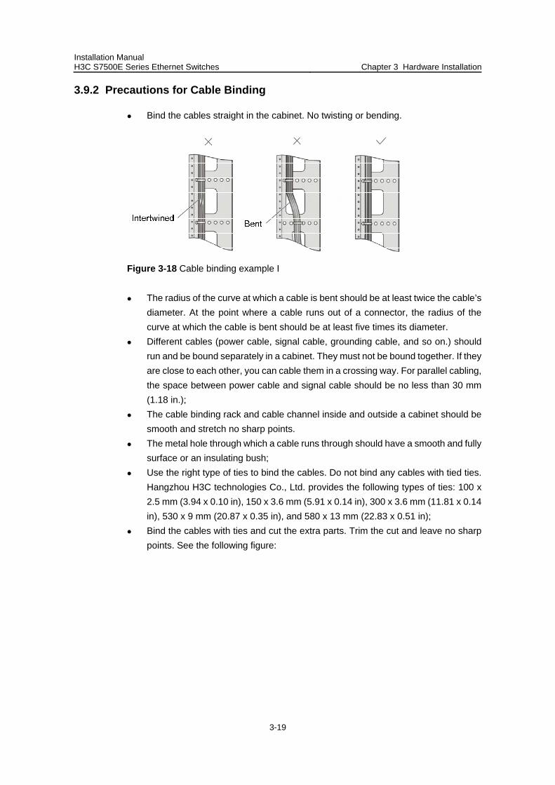
Installation Manual H3C S7500E Series Ethernet Switches Chapter 3 Hardware Installation
3-19
3.9.2 Precautions for Cable Binding
Bind the cables straight in the cabinet. No twisting or bending.
Figure 3-18 Cable binding example I
The radius of the curve at which a cable is bent should be at least twice the cable’s diameter. At the point where a cable runs out of a connector, the radius of the curve at which the cable is bent should be at least five times its diameter.
Different cables (power cable, signal cable, grounding cable, and so on.) should run and be bound separately in a cabinet. They must not be bound together. If they are close to each other, you can cable them in a crossing way. For parallel cabling, the space between power cable and signal cable should be no less than 30 mm (1.18 in.);
The cable binding rack and cable channel inside and outside a cabinet should be smooth and stretch no sharp points.
The metal hole through which a cable runs through should have a smooth and fully surface or an insulating bush;
Use the right type of ties to bind the cables. Do not bind any cables with tied ties. Hangzhou H3C technologies Co., Ltd. provides the following types of ties: 100 x 2.5 mm (3.94 x 0.10 in), 150 x 3.6 mm (5.91 x 0.14 in), 300 x 3.6 mm (11.81 x 0.14 in), 530 x 9 mm (20.87 x 0.35 in), and 580 x 13 mm (22.83 x 0.51 in);
Bind the cables with ties and cut the extra parts. Trim the cut and leave no sharp points. See the following figure:
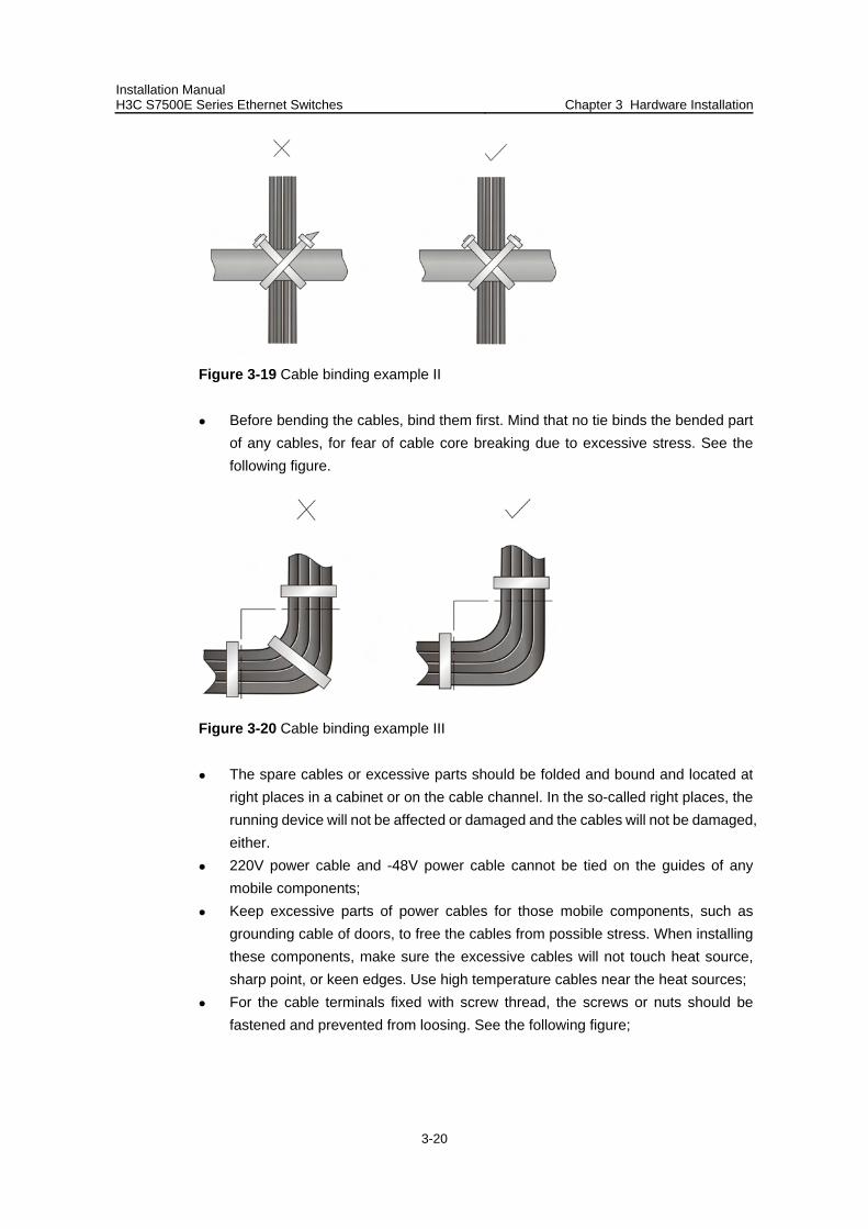
Installation Manual H3C S7500E Series Ethernet Switches Chapter 3 Hardware Installation
3-20
Figure 3-19 Cable binding example II
Before bending the cables, bind them first. Mind that no tie binds the bended part of any cables, for fear of cable core breaking due to excessive stress. See the following figure.
Figure 3-20 Cable binding example III
The spare cables or excessive parts should be folded and bound and located at right places in a cabinet or on the cable channel. In the so-called right places, the running device will not be affected or damaged and the cables will not be damaged, either.
220V power cable and -48V power cable cannot be tied on the guides of any mobile components;
Keep excessive parts of power cables for those mobile components, such as grounding cable of doors, to free the cables from possible stress. When installing these components, make sure the excessive cables will not touch heat source, sharp point, or keen edges. Use high temperature cables near the heat sources;
For the cable terminals fixed with screw thread, the screws or nuts should be fastened and prevented from loosing. See the following figure;
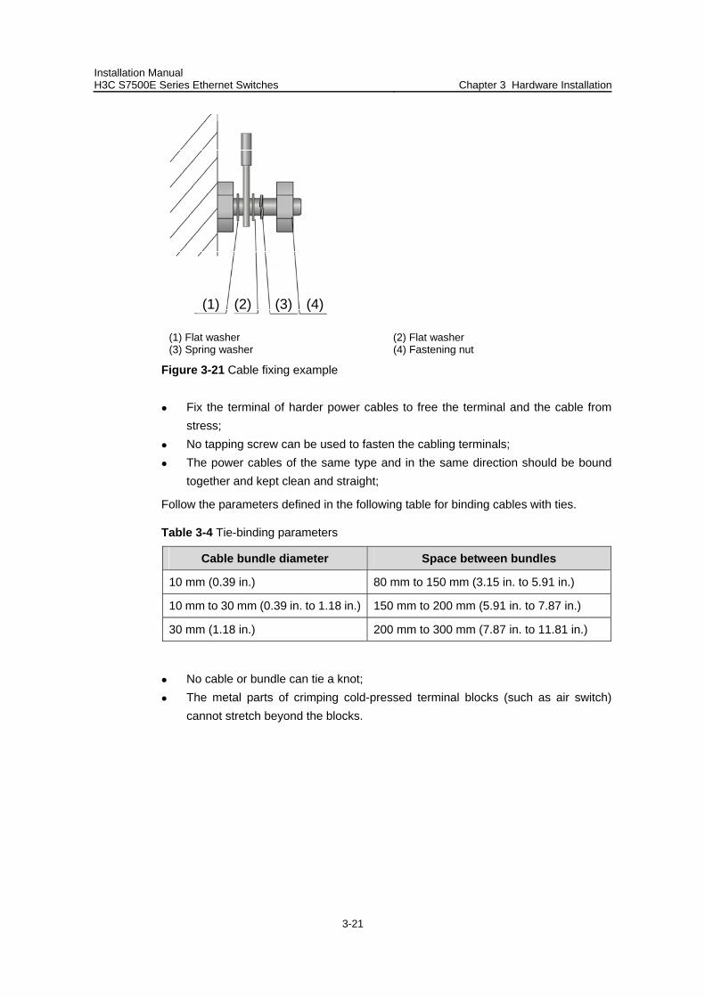
Installation Manual H3C S7500E Series Ethernet Switches Chapter 3 Hardware Installation
3-21
(1) (2) (3) (4)
(1) Flat washer (2) Flat washer (3) Spring washer (4) Fastening nut
Figure 3-21 Cable fixing example
Fix the terminal of harder power cables to free the terminal and the cable from stress;
No tapping screw can be used to fasten the cabling terminals; The power cables of the same type and in the same direction should be bound
together and kept clean and straight;
Follow the parameters defined in the following table for binding cables with ties.
Table 3-4 Tie-binding parameters
Cable bundle diameter Space between bundles
10 mm (0.39 in.) 80 mm to 150 mm (3.15 in. to 5.91 in.)
10 mm to 30 mm (0.39 in. to 1.18 in.) 150 mm to 200 mm (5.91 in. to 7.87 in.)
30 mm (1.18 in.) 200 mm to 300 mm (7.87 in. to 11.81 in.)
No cable or bundle can tie a knot; The metal parts of crimping cold-pressed terminal blocks (such as air switch)
cannot stretch beyond the blocks.
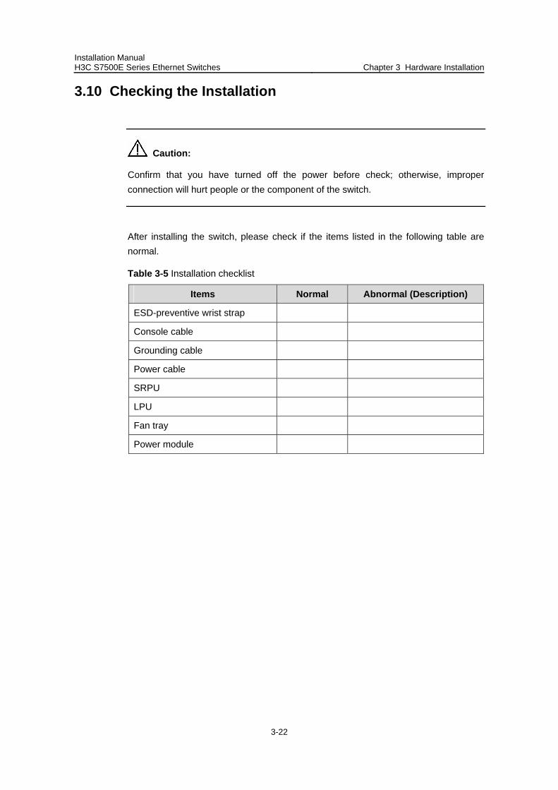
Installation Manual H3C S7500E Series Ethernet Switches Chapter 3 Hardware Installation
3-22
3.10 Checking the Installation
Caution:
Confirm that you have turned off the power before check; otherwise, improper connection will hurt people or the component of the switch.
After installing the switch, please check if the items listed in the following table are normal.
Table 3-5 Installation checklist
Items Normal Abnormal (Description)
ESD-preventive wrist strap
Console cable
Grounding cable
Power cable
SRPU
LPU
Fan tray
Power module
Installation Manual H3C S7500E Series Ethernet Switches Table of Contents
i
Table of Contents
Chapter 4 System Commissioning.............................................................................................. 4-1 4.1 Configuration Environment Setup...................................................................................... 4-1
4.1.1 Setting up Networking Environment........................................................................ 4-1 4.1.2 Connecting the Console Cable ............................................................................... 4-1 4.1.3 Setting Terminal Parameters .................................................................................. 4-1
4.2 Power-On Startup .............................................................................................................. 4-5 4.2.1 Check before Power-On.......................................................................................... 4-5 4.2.2 Power-On ................................................................................................................ 4-6 4.2.3 Check after Power-On (Recommended)................................................................. 4-6 4.2.4 Startup Process....................................................................................................... 4-6
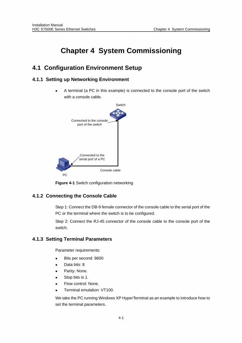
Installation Manual H3C S7500E Series Ethernet Switches Chapter 4 System Commissioning
4-1
Chapter 4 System Commissioning
4.1 Configuration Environment Setup
4.1.1 Setting up Networking Environment
A terminal (a PC in this example) is connected to the console port of the switch with a console cable.
Console cablePC
Switch
Connected to the serial port of a PC
Connected to the console port of the switch
Figure 4-1 Switch configuration networking
4.1.2 Connecting the Console Cable
Step 1: Connect the DB-9 female connector of the console cable to the serial port of the PC or the terminal where the switch is to be configured.
Step 2: Connect the RJ-45 connector of the console cable to the console port of the switch.
4.1.3 Setting Terminal Parameters
Parameter requirements:
Bits per second: 9600 Data bits: 8 Parity: None. Stop bits is 1. Flow control: None. Terminal emulation: VT100.
We take the PC running Windows XP HyperTerminal as an example to introduce how to set the terminal parameters.
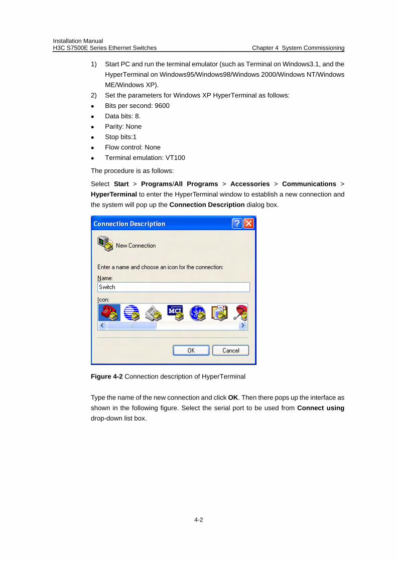
Installation Manual H3C S7500E Series Ethernet Switches Chapter 4 System Commissioning
4-2
1) Start PC and run the terminal emulator (such as Terminal on Windows3.1, and the HyperTerminal on Windows95/Windows98/Windows 2000/Windows NT/Windows ME/Windows XP).
2) Set the parameters for Windows XP HyperTerminal as follows: Bits per second: 9600 Data bits: 8. Parity: None Stop bits:1 Flow control: None Terminal emulation: VT100
The procedure is as follows:
Select Start > Programs/All Programs > Accessories > Communications > HyperTerminal to enter the HyperTerminal window to establish a new connection and the system will pop up the Connection Description dialog box.
Figure 4-2 Connection description of HyperTerminal
Type the name of the new connection and click OK. Then there pops up the interface as shown in the following figure. Select the serial port to be used from Connect using drop-down list box.
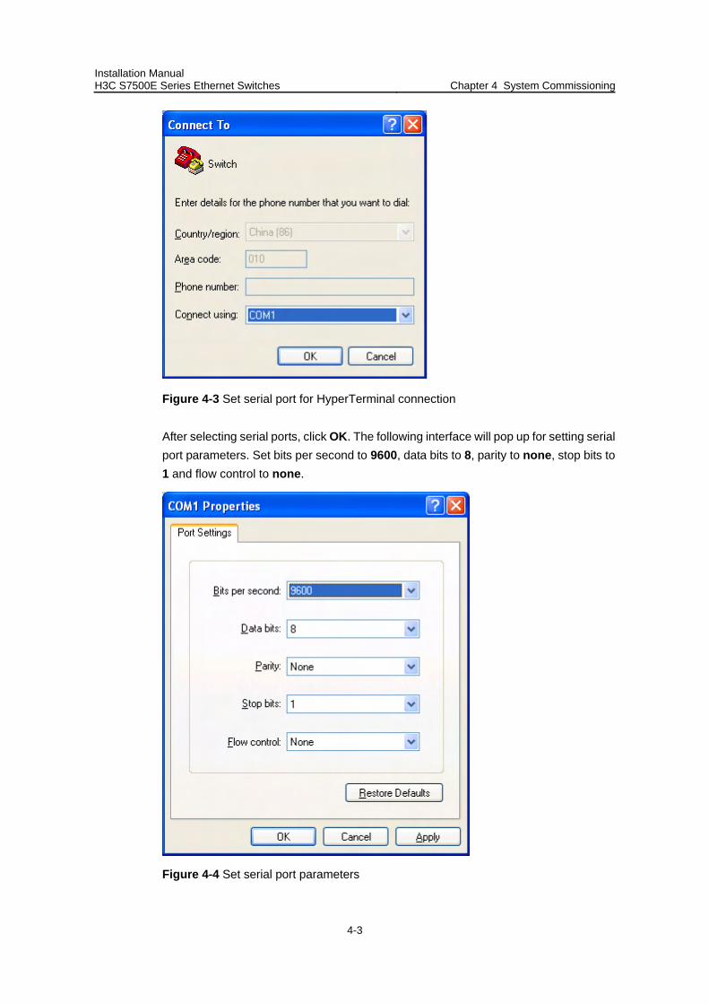
Installation Manual H3C S7500E Series Ethernet Switches Chapter 4 System Commissioning
4-3
Figure 4-3 Set serial port for HyperTerminal connection
After selecting serial ports, click OK. The following interface will pop up for setting serial port parameters. Set bits per second to 9600, data bits to 8, parity to none, stop bits to 1 and flow control to none.
Figure 4-4 Set serial port parameters
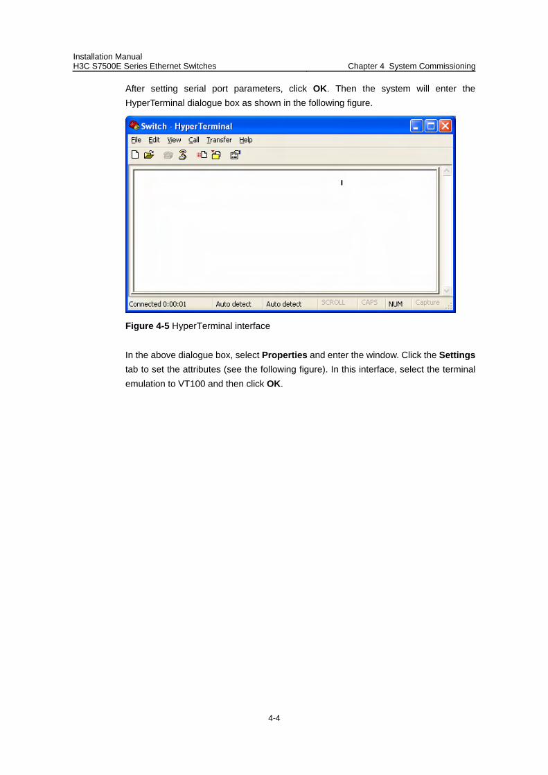
Installation Manual H3C S7500E Series Ethernet Switches Chapter 4 System Commissioning
4-4
After setting serial port parameters, click OK. Then the system will enter the HyperTerminal dialogue box as shown in the following figure.
Figure 4-5 HyperTerminal interface
In the above dialogue box, select Properties and enter the window. Click the Settings tab to set the attributes (see the following figure). In this interface, select the terminal emulation to VT100 and then click OK.
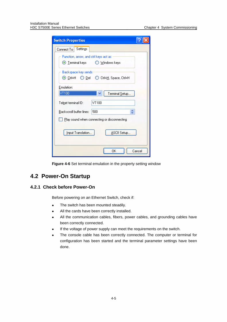
Installation Manual H3C S7500E Series Ethernet Switches Chapter 4 System Commissioning
4-5
Figure 4-6 Set terminal emulation in the property setting window
4.2 Power-On Startup
4.2.1 Check before Power-On
Before powering on an Ethernet Switch, check if:
The switch has been mounted steadily. All the cards have been correctly installed. All the communication cables, fibers, power cables, and grounding cables have
been correctly connected. If the voltage of power supply can meet the requirements on the switch. The console cable has been correctly connected. The computer or terminal for
configuration has been started and the terminal parameter settings have been done.
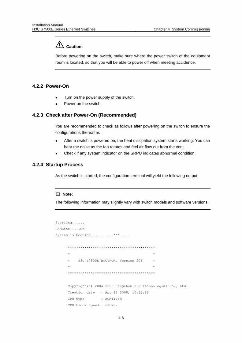
Installation Manual H3C S7500E Series Ethernet Switches Chapter 4 System Commissioning
4-6
Caution:
Before powering on the switch, make sure where the power switch of the equipment room is located, so that you will be able to power off when meeting accidence.
4.2.2 Power-On
Turn on the power supply of the switch. Power on the switch.
4.2.3 Check after Power-On (Recommended)
You are recommended to check as follows after powering on the switch to ensure the configurations thereafter.
After a switch is powered on, the heat dissipation system starts working. You can hear the noise as the fan rotates and feel air flow out from the vent.
Check if any system indicator on the SRPU indicates abnormal condition.
4.2.4 Startup Process
As the switch is started, the configuration terminal will yield the following output:
Note:
The following information may slightly vary with switch models and software versions.
Starting......
RAMLine.....OK
System is booting...........***.....
******************************************
* *
* H3C S7500E BOOTROM, Version 206 *
* *
******************************************
Copyright(c) 2004-2008 Hangzhou H3C Technologies Co., Ltd.
Creation date : Apr 11 2008, 10:15:28
CPU type : BCM1125H
CPU Clock Speed : 600Mhz

Installation Manual H3C S7500E Series Ethernet Switches Chapter 4 System Commissioning
4-7
BUS Clock Speed : 66Mhz
BOOT_FLASH type : M29W040B
Flash Size : 64MB
Memory Size : 512MB
Main board slot 0 self testing............................
SDRAM Data lines selftest.................................OK!
SDRAM Address lines selftest..............................OK!
SDRAM fast selftest.......................................OK!
CPLD selftest.............................................OK!
FPGA selftest.............................................OK!
The switch Mac address is .....................0000.FC00.7506
Press Ctrl+B to enter Boot Menu... 5
Auto-booting....................
Auto booting file is flash:/ s7500e.app...OK
Decompress Image..........................................................
..........................................................................
..........................................................................
..........................................................................
..........................................................................
..........................................................................
........................................................................
..........................................................................
..........................................................................
.....................................................................OK!
Starting at 0x80020000...
User interface aux0 is available.
Press ENTER to get started.
The above information indicates the completion of the switch auto-booting.
Press Enter and get the following output. By this time, you can start configuring the switch.
<H3C>

Installation Manual H3C S7500E Series Ethernet Switches Chapter 4 System Commissioning
4-8
Note:
H3C S7500E series switches provide a variety of command views. For the specific descriptions on the configuration commands and command line interfaces, refer to Operation Manual and Command Manual of the H3C S7500E Series Ethernet Switches.
Installation Manual H3C S7500E Series Ethernet Switches Table of Contents
i
Table of Contents
Chapter 5 Hardware Maintenance................................................................................................ 5-1 5.1 Required Tools................................................................................................................... 5-1 5.2 Removing and Installing a Power Module ......................................................................... 5-1
5.2.1 Removing and Installing a Power Module............................................................... 5-2 5.3 Removing and Installing Cards.......................................................................................... 5-3
5.3.1 Removing a Card .................................................................................................... 5-4 5.3.2 Installing a Card ...................................................................................................... 5-5
5.4 Removing and Installing a Fan Tray.................................................................................. 5-5 5.4.1 For the S7506E-V ................................................................................................... 5-6 5.4.2 For the Other Models .............................................................................................. 5-7
5.5 Installing Mounting Ears and a Cabling Rack(s)................................................................ 5-7 5.5.1 Installing Cabling Racks on the S7506E-V ............................................................. 5-8 5.5.2 Installing Mounting Ears and the Cabling Rack on the Other Models .................... 5-8
5.6 Installing and Removing Air Filters (Optional) ................................................................. 5-10 5.6.1 Installing and Removing Air Filters onto/from the S7506E-V................................ 5-10 5.6.2 Installing and Removing an Air Filter onto/from the Other Models ....................... 5-11
5.7 Installing and Removing a CF Card................................................................................. 5-12 5.7.1 CF Card Slot and CFS LED .................................................................................. 5-12 5.7.2 Install a CF Card ................................................................................................... 5-12 5.7.3 Removing the CF Card ......................................................................................... 5-12
Installation Manual H3C S7500E Series Ethernet Switches Chapter 5 Hardware Maintenance
5-1
Chapter 5 Hardware Maintenance
Caution:
The power modules of the S7500E series are hot-swappable. When installing or replacing an in-service power module, pay attention to operations and electrical safety. Do not touch any naked wire, terminal or any part of the product labeled with a dangerous voltage to avoid injury.
5.1 Required Tools
ESD-preventive wrist strap Screwdriver
5.2 Removing and Installing a Power Module
The power module installation and removal procedures described in this section involve the following two scenarios:
Power modules are directly installed to/removed from the chassis. Power modules are installed to/removed from the chassis with power module
adapters.
In the second scenario, you need to install a power module adapter to the chassis first and then install a power module to the power module adapter. The installation and removal methods in this scenario are the same as in the first scenario.
The following describes how to install and remove a power module in the first scenario.
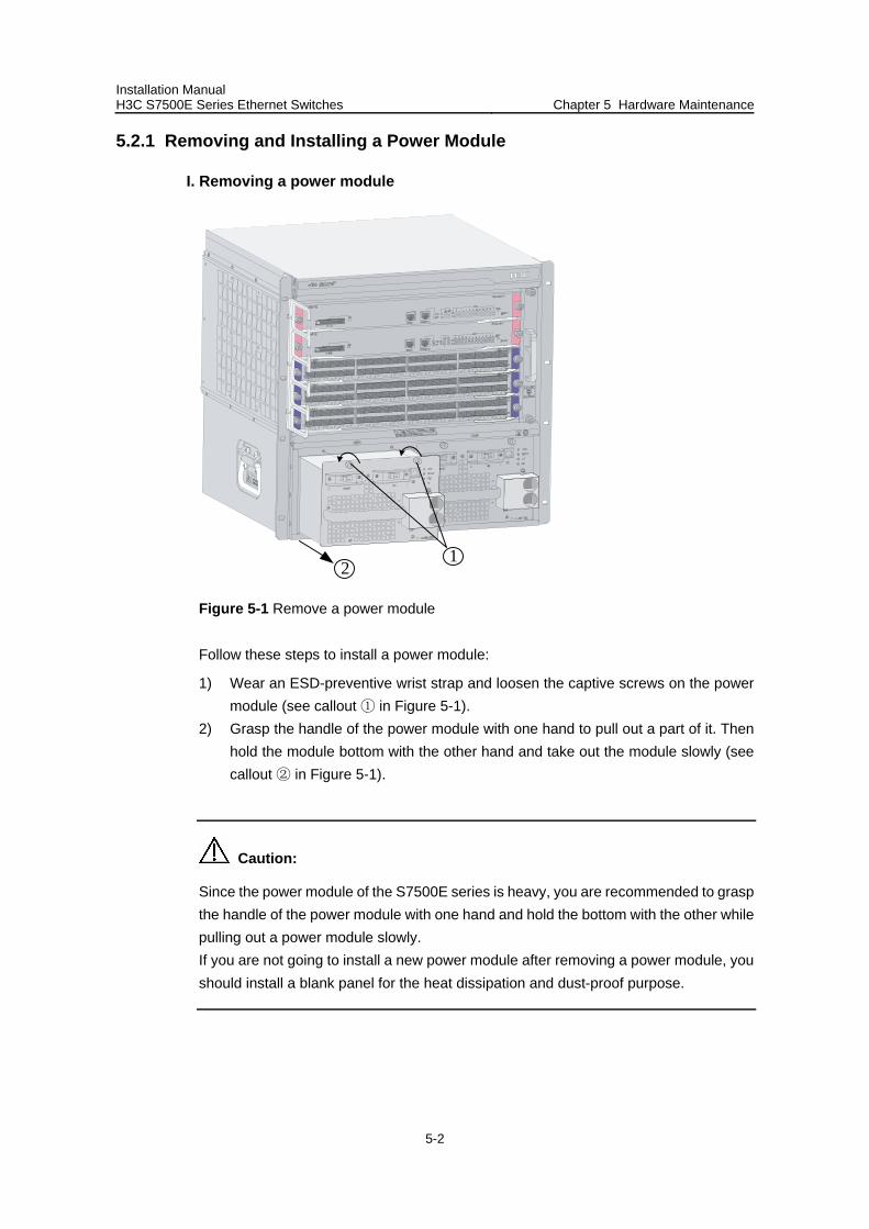
Installation Manual H3C S7500E Series Ethernet Switches Chapter 5 Hardware Maintenance
5-2
5.2.1 Removing and Installing a Power Module
I. Removing a power module
21
Figure 5-1 Remove a power module
Follow these steps to install a power module:
1) Wear an ESD-preventive wrist strap and loosen the captive screws on the power module (see callout in ① Figure 5-1).
2) Grasp the handle of the power module with one hand to pull out a part of it. Then hold the module bottom with the other hand and take out the module slowly (see callout in ② Figure 5-1).
Caution:
Since the power module of the S7500E series is heavy, you are recommended to grasp the handle of the power module with one hand and hold the bottom with the other while pulling out a power module slowly. If you are not going to install a new power module after removing a power module, you should install a blank panel for the heat dissipation and dust-proof purpose.
Installation Manual H3C S7500E Series Ethernet Switches Chapter 5 Hardware Maintenance
5-3
II. Installing a power module
Install a power module in the opposite order you remove it:
1) Put on an ESD-preventive wrist strap and take a new power module out of its package. Check that the input mode of the power module is as required.
2) Grasp the handle of the module with one hand and hold the module bottom with the other. Gently push the power module along the guide rails into the chassis until it has firm contact with the connector on the backplane.
Caution:
Be sure not to insert the power module with its front panel upside down. Follow the forward inertia of the power module when inserting it into the chassis to ensure that the power module has firm contact with the connector on backplane. To prevent damage to the power module and the connection terminals on the backplane, make sure to pull the module out first in case of any misalignment, and then push it in again.
3) Tighten the captive screws with a screwdriver to secure the power module to the chassis.
Caution:
If the captive screws cannot be tightened, check whether the power module is properly installed.
5.3 Removing and Installing Cards
SRPUs and LPUs of the S7500E series are basically of the same structure. These cards share similar installation and removal methods. This section describes the general installation and removal methods.
Cards of the S7500E series are hot-swappable.
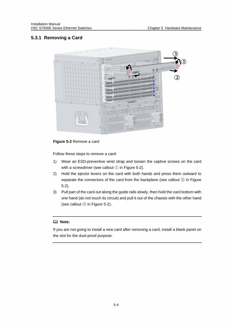
Installation Manual H3C S7500E Series Ethernet Switches Chapter 5 Hardware Maintenance
5-4
5.3.1 Removing a Card
3
1
2
Figure 5-2 Remove a card
Follow these steps to remove a card:
1) Wear an ESD-preventive wrist strap and loosen the captive screws on the card with a screwdriver (see callout in ① Figure 5-2).
2) Hold the ejector levers on the card with both hands and press them outward to separate the connectors of the card from the backplane (see callout in ② Figure 5-2).
3) Pull part of the card out along the guide rails slowly, then hold the card bottom with one hand (do not touch its circuit) and pull it out of the chassis with the other hand (see callout in ③ Figure 5-2).
Note:
If you are not going to install a new card after removing a card, install a blank panel on the slot for the dust-proof purpose.
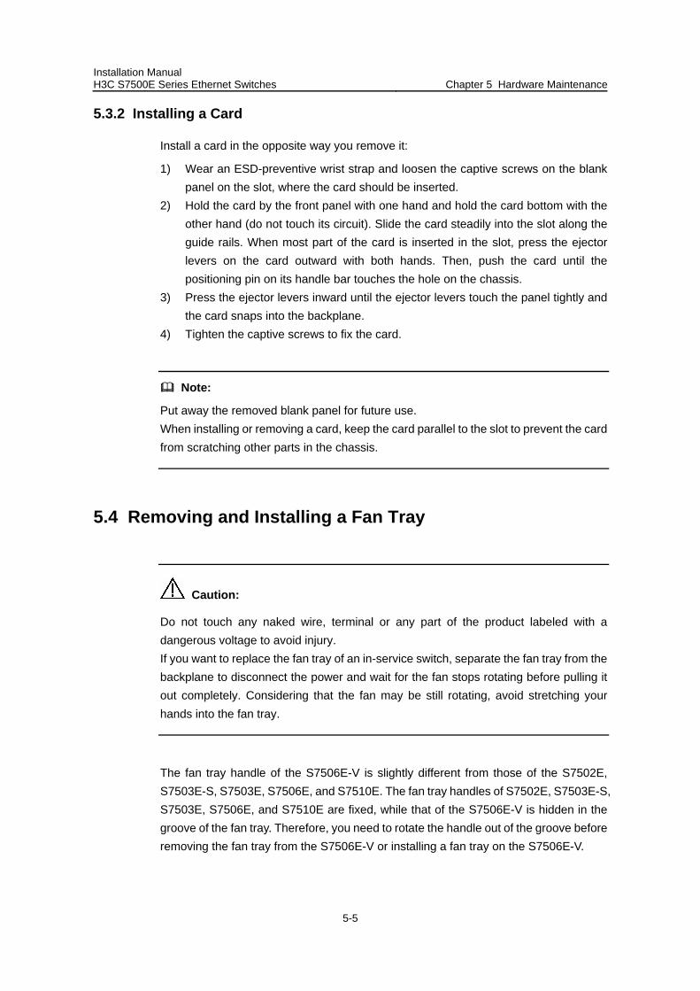
Installation Manual H3C S7500E Series Ethernet Switches Chapter 5 Hardware Maintenance
5-5
5.3.2 Installing a Card
Install a card in the opposite way you remove it:
1) Wear an ESD-preventive wrist strap and loosen the captive screws on the blank panel on the slot, where the card should be inserted.
2) Hold the card by the front panel with one hand and hold the card bottom with the other hand (do not touch its circuit). Slide the card steadily into the slot along the guide rails. When most part of the card is inserted in the slot, press the ejector levers on the card outward with both hands. Then, push the card until the positioning pin on its handle bar touches the hole on the chassis.
3) Press the ejector levers inward until the ejector levers touch the panel tightly and the card snaps into the backplane.
4) Tighten the captive screws to fix the card.
Note:
Put away the removed blank panel for future use. When installing or removing a card, keep the card parallel to the slot to prevent the card from scratching other parts in the chassis.
5.4 Removing and Installing a Fan Tray
Caution:
Do not touch any naked wire, terminal or any part of the product labeled with a dangerous voltage to avoid injury. If you want to replace the fan tray of an in-service switch, separate the fan tray from the backplane to disconnect the power and wait for the fan stops rotating before pulling it out completely. Considering that the fan may be still rotating, avoid stretching your hands into the fan tray.
The fan tray handle of the S7506E-V is slightly different from those of the S7502E, S7503E-S, S7503E, S7506E, and S7510E. The fan tray handles of S7502E, S7503E-S, S7503E, S7506E, and S7510E are fixed, while that of the S7506E-V is hidden in the groove of the fan tray. Therefore, you need to rotate the handle out of the groove before removing the fan tray from the S7506E-V or installing a fan tray on the S7506E-V.
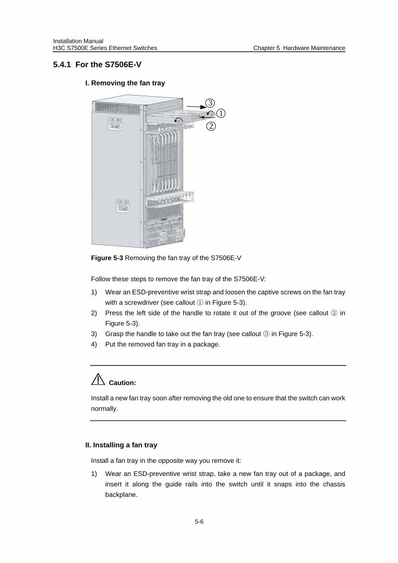
Installation Manual H3C S7500E Series Ethernet Switches Chapter 5 Hardware Maintenance
5-6
5.4.1 For the S7506E-V
I. Removing the fan tray
12
3
Figure 5-3 Removing the fan tray of the S7506E-V
Follow these steps to remove the fan tray of the S7506E-V:
1) Wear an ESD-preventive wrist strap and loosen the captive screws on the fan tray with a screwdriver (see callout in ① Figure 5-3).
2) Press the left side of the handle to rotate it out of the groove (see callout ② in Figure 5-3).
3) Grasp the handle to take out the fan tray (see callout in ③ Figure 5-3). 4) Put the removed fan tray in a package.
Caution:
Install a new fan tray soon after removing the old one to ensure that the switch can work normally.
II. Installing a fan tray
Install a fan tray in the opposite way you remove it:
1) Wear an ESD-preventive wrist strap, take a new fan tray out of a package, and insert it along the guide rails into the switch until it snaps into the chassis backplane.
Installation Manual H3C S7500E Series Ethernet Switches Chapter 5 Hardware Maintenance
5-7
2) Tighten the captive screws with a screwdriver. 3) Push the handle into the groove.
5.4.2 For the Other Models
I. Removing the fan tray
Figure 5-4 Remove the fan tray of the other models
Follow these steps to remove the fan tray of other models:
1) Wear an ESD-preventive wrist strap and loosen the captive screws on the fan tray with a screwdriver (see callout ① in Figure 5-4).
2) Drag the fan tray out of the slot (see callout ② in Figure 5-4). 3) Put the removed fan tray into a package.
II. Installing a fan tray
Install a fan tray in the opposite way you remove it:
1) Take a new fan tray out of a package and slide it along the guide rails into the switch until it snaps into the chassis backplane.
2) Tighten the captive screws on the fan tray with a screwdriver.
5.5 Installing Mounting Ears and a Cabling Rack(s)
To facilitate installation and cable routing, mounting ears and a cabling rack are shipped together with the S7500E series, but they are separated. Therefore, you first need to install the cabling rack on a mounting ear.
For the S7506E-V, it is unnecessary to install cabling racks onto mounting ears. Two cabling racks are provided for the S7506E-V: upward cabling rack and downward cabling rack. These two cabling racks are different. The cabling rack with a tray should
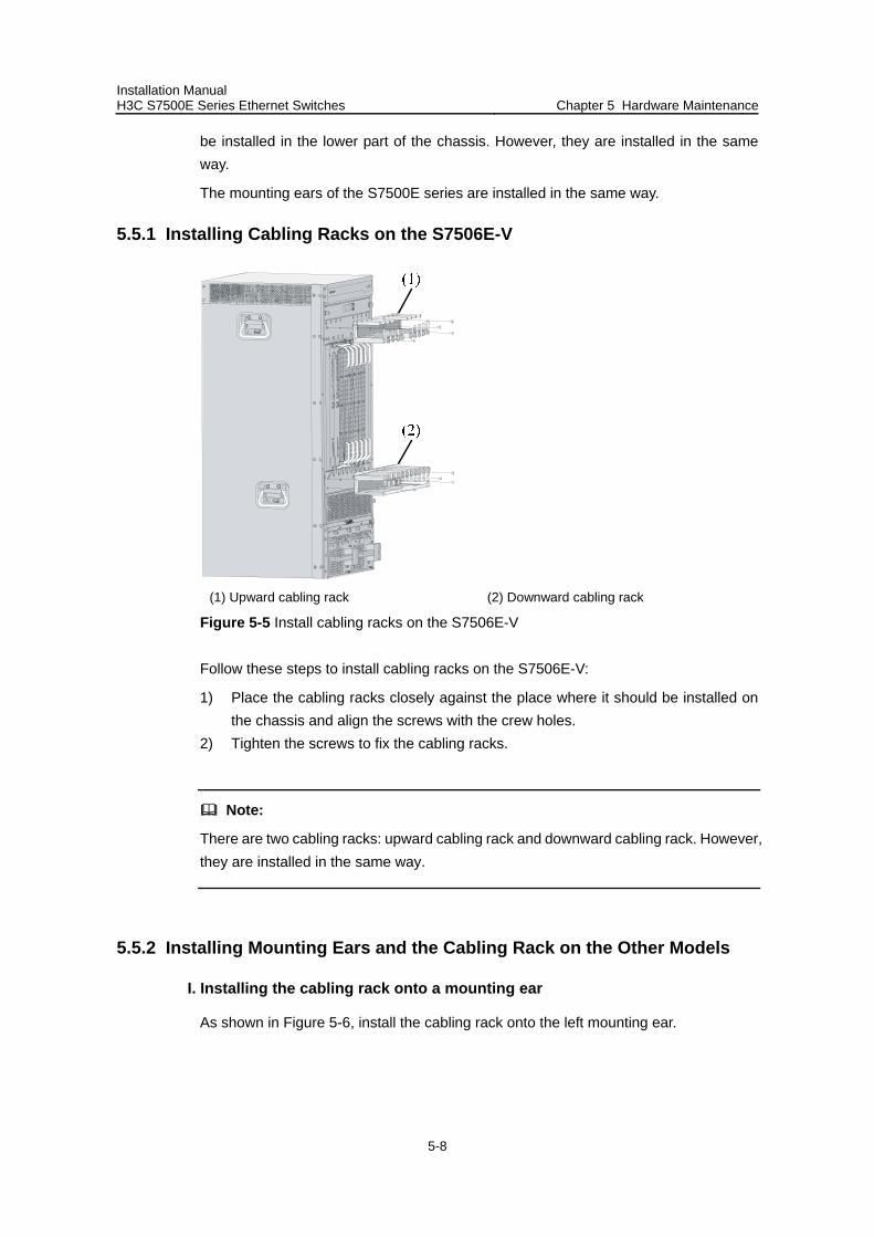
Installation Manual H3C S7500E Series Ethernet Switches Chapter 5 Hardware Maintenance
5-8
be installed in the lower part of the chassis. However, they are installed in the same way.
The mounting ears of the S7500E series are installed in the same way.
5.5.1 Installing Cabling Racks on the S7506E-V
(1) Upward cabling rack (2) Downward cabling rack
Figure 5-5 Install cabling racks on the S7506E-V
Follow these steps to install cabling racks on the S7506E-V:
1) Place the cabling racks closely against the place where it should be installed on the chassis and align the screws with the crew holes.
2) Tighten the screws to fix the cabling racks.
Note:
There are two cabling racks: upward cabling rack and downward cabling rack. However, they are installed in the same way.
5.5.2 Installing Mounting Ears and the Cabling Rack on the Other Models
I. Installing the cabling rack onto a mounting ear
As shown in Figure 5-6, install the cabling rack onto the left mounting ear.
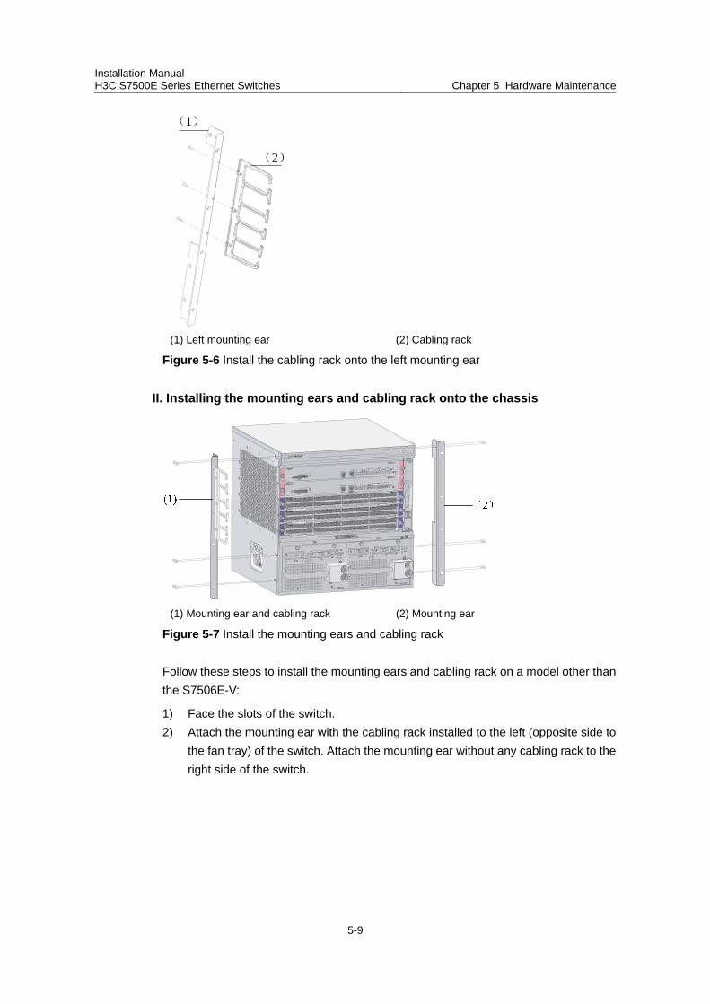
Installation Manual H3C S7500E Series Ethernet Switches Chapter 5 Hardware Maintenance
5-9
(1)
(2)
(1) Left mounting ear (2) Cabling rack
Figure 5-6 Install the cabling rack onto the left mounting ear
II. Installing the mounting ears and cabling rack onto the chassis
(1) Mounting ear and cabling rack (2) Mounting ear
Figure 5-7 Install the mounting ears and cabling rack
Follow these steps to install the mounting ears and cabling rack on a model other than the S7506E-V:
1) Face the slots of the switch. 2) Attach the mounting ear with the cabling rack installed to the left (opposite side to
the fan tray) of the switch. Attach the mounting ear without any cabling rack to the right side of the switch.
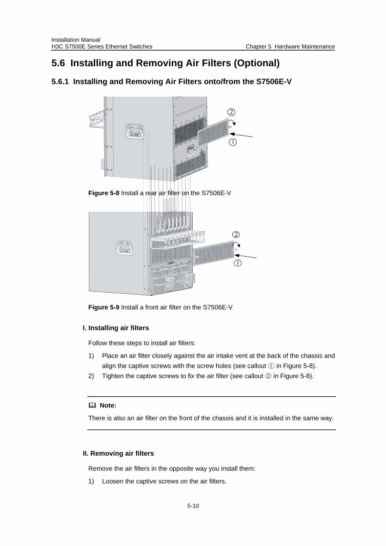
Installation Manual H3C S7500E Series Ethernet Switches Chapter 5 Hardware Maintenance
5-10
5.6 Installing and Removing Air Filters (Optional)
5.6.1 Installing and Removing Air Filters onto/from the S7506E-V
Figure 5-8 Install a rear air filter on the S7506E-V
Figure 5-9 Install a front air filter on the S7506E-V
I. Installing air filters
Follow these steps to install air filters:
1) Place an air filter closely against the air intake vent at the back of the chassis and align the captive screws with the screw holes (see callout in ① Figure 5-8).
2) Tighten the captive screws to fix the air filter (see callout in ② Figure 5-8).
Note:
There is also an air filter on the front of the chassis and it is installed in the same way.
II. Removing air filters
Remove the air filters in the opposite way you install them:
1) Loosen the captive screws on the air filters.
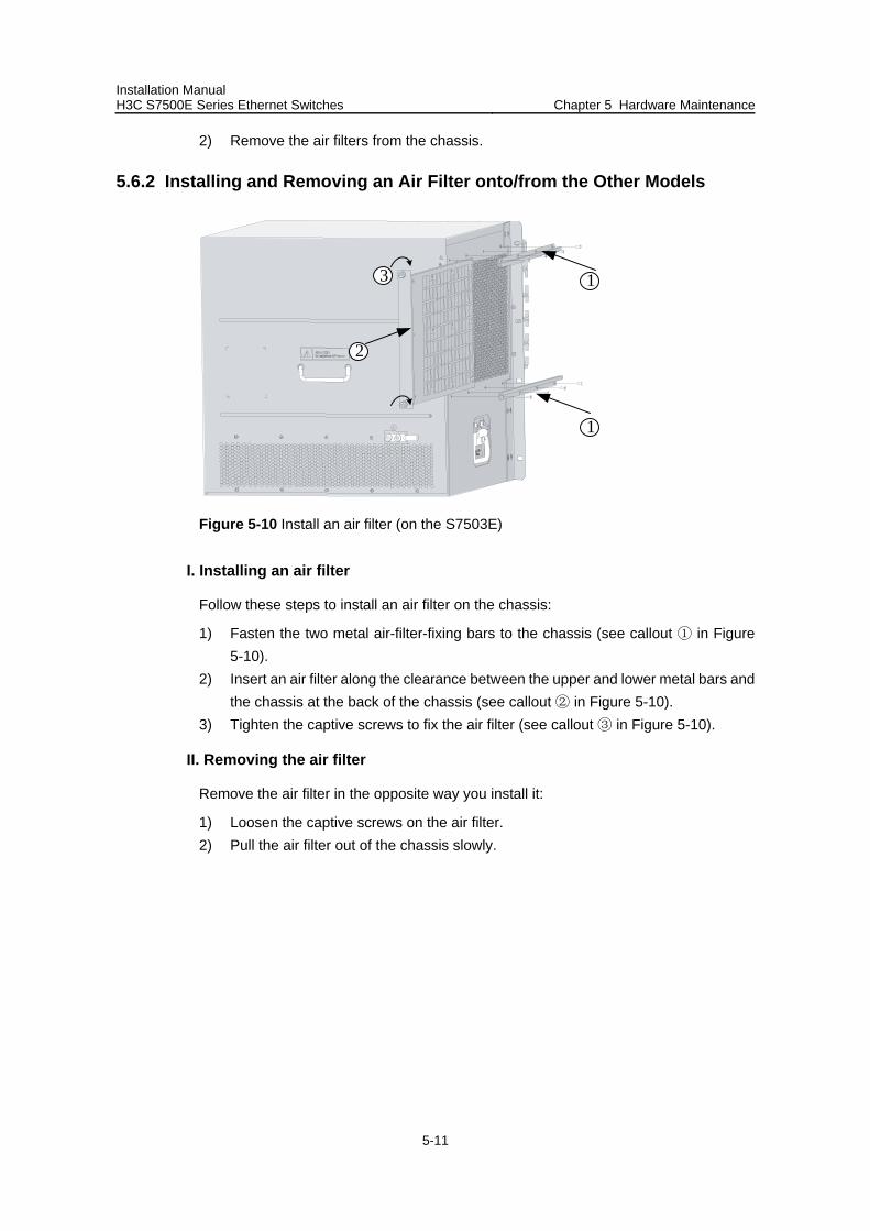
Installation Manual H3C S7500E Series Ethernet Switches Chapter 5 Hardware Maintenance
5-11
2) Remove the air filters from the chassis.
5.6.2 Installing and Removing an Air Filter onto/from the Other Models
1
2
1
3
Figure 5-10 Install an air filter (on the S7503E)
I. Installing an air filter
Follow these steps to install an air filter on the chassis:
1) Fasten the two metal air-filter-fixing bars to the chassis (see callout in ① Figure 5-10).
2) Insert an air filter along the clearance between the upper and lower metal bars and the chassis at the back of the chassis (see callout in ② Figure 5-10).
3) Tighten the captive screws to fix the air filter (see callout in ③ Figure 5-10).
II. Removing the air filter
Remove the air filter in the opposite way you install it:
1) Loosen the captive screws on the air filter. 2) Pull the air filter out of the chassis slowly.
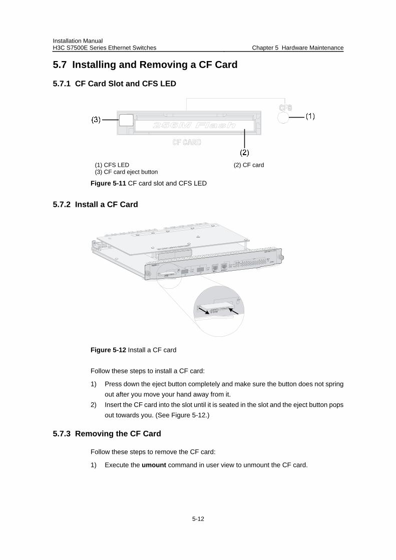
Installation Manual H3C S7500E Series Ethernet Switches Chapter 5 Hardware Maintenance
5-12
5.7 Installing and Removing a CF Card
5.7.1 CF Card Slot and CFS LED
(1) CFS LED (2) CF card (3) CF card eject button
Figure 5-11 CF card slot and CFS LED
5.7.2 Install a CF Card
Figure 5-12 Install a CF card
Follow these steps to install a CF card:
1) Press down the eject button completely and make sure the button does not spring out after you move your hand away from it.
2) Insert the CF card into the slot until it is seated in the slot and the eject button pops out towards you. (See Figure 5-12.)
5.7.3 Removing the CF Card
Follow these steps to remove the CF card:
1) Execute the umount command in user view to unmount the CF card.
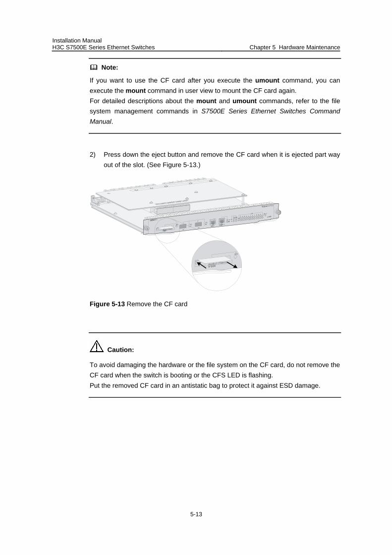
Installation Manual H3C S7500E Series Ethernet Switches Chapter 5 Hardware Maintenance
5-13
Note:
If you want to use the CF card after you execute the umount command, you can execute the mount command in user view to mount the CF card again. For detailed descriptions about the mount and umount commands, refer to the file system management commands in S7500E Series Ethernet Switches Command Manual.
2) Press down the eject button and remove the CF card when it is ejected part way out of the slot. (See Figure 5-13.)
Figure 5-13 Remove the CF card
Caution:
To avoid damaging the hardware or the file system on the CF card, do not remove the CF card when the switch is booting or the CFS LED is flashing. Put the removed CF card in an antistatic bag to protect it against ESD damage.
Installation Manual H3C S7500E Series Ethernet Switches Table of Contents
i
Table of Contents
Chapter 6 Software Maintenance................................................................................................. 6-1 6.1 Software Maintenance Overview....................................................................................... 6-1 6.2 Upgrading Through the Boot Menu ................................................................................... 6-1
6.2.1 BOOT Menu ............................................................................................................ 6-2 6.2.2 Downloading Through the Management/Upgrade Ethernet Port Using TFTP ............... 6-3 6.2.3 Downloading Through the Management/Upgrade Ethernet Port Using FTP ......... 6-5 6.2.4 Downloading Through the Console Port Using XMODEM ..................................... 6-8 6.2.5 Setting the Main and Backup Host Software Through the Boot Menu ................. 6-13 6.2.6 Updating Boot ROM Through a File on the Flash................................................. 6-15
6.3 Upgrading Through Command Lines............................................................................... 6-17 6.3.1 Upgrading Using FTP............................................................................................ 6-17 6.3.2 Upgrading Using TFTP ......................................................................................... 6-18
6.4 Examples of Upgrading Boot ROM and Host Software of the Dual SRPUs ................... 6-18 6.4.1 Upgrading Boot ROM and Host Software Through Command Lines ................... 6-18 6.4.2 Upgrading Through the Boot Menu....................................................................... 6-21
6.5 Handling Upgrade Failure................................................................................................ 6-22 6.6 Handling Password Loss ................................................................................................. 6-22
Installation Manual H3C S7500E Series Ethernet Switches Chapter 6 Software Maintenance
6-1
Chapter 6 Software Maintenance
6.1 Software Maintenance Overview
Software maintenance of a switch means to upgrade the switch host software and Boot ROM through the host software package, which contains the host software and the Boot ROM program, and is with the extension name of .app (S7500E.app for example).
Host software upgrade involves downloading the host software package onto the Flash of both the active and standby SRPUs, and setting the main and backup boot files.
Boot ROM upgrade involves upgrading the Boot ROM of the SRPUs and LPUs through the Boot ROM program in the host software package.
There are two ways to upgrade host software and Boot ROM programs:
Upgrade through boot menu. Upgrade through command lines.
However, you can upgrade the Boot ROM program of LPUs through command lines only.
Note:
To ensure the software version consistency between the active and standby SRPUs, upgrade the software in the same way, that is, upgrade the software on both the active and standby SRPUs either through command lines or through the boot menu.
Since upgrading through command lines affects the services of the S7500E series less significantly than upgrading through the boot menu, the former is recommended.
6.2 Upgrading Through the Boot Menu
You can download the host software package onto the Flash of a switch in one of the following ways:
Download through a management/upgrade Ethernet port using TFTP Download through a management/upgrade Ethernet port using FTP Download through the console port using XMODEM
After downloading the host software package onto the Flash, specify the main/backup boot file to complete the host software upgrade. If you need to upgrade the Boot ROM

Installation Manual H3C S7500E Series Ethernet Switches Chapter 6 Software Maintenance
6-2
of the SRPUs through the boot menu, refer to section 6.2.6 “Updating Boot ROM Through a File on the Flash” on page 6-15.
6.2.1 BOOT Menu
Upon power-on, the switch will run the Boot ROM program first. The following information will be displayed on the terminal:
Starting......
RAMLine.....OK
System is booting...........***.....
******************************************
* *
* H3C S7500E BOOTROM, Version 206 *
* *
******************************************
Copyright(c) 2004-2008 Hangzhou H3C Technologies Co., Ltd.
Creation date : Apr 11 2008, 10:15:28
CPU type : BCM1125H
CPU Clock Speed : 600Mhz
BUS Clock Speed : 66Mhz
BOOT_FLASH type : M29W040B
Flash Size : 64MB
Memory Size : 512MB
Main board slot 0 self testing............................
SDRAM Data lines selftest.................................OK!
SDRAM Address lines selftest..............................OK!
SDRAM fast selftest.......................................OK!
CPLD selftest.............................................OK!
FPGA selftest.............................................OK!
The switch Mac address is .....................0000.FC00.7506
Note:
The above information may vary slightly with the models of S7500E series.
Press Ctrl+B to enter Boot Menu... 5
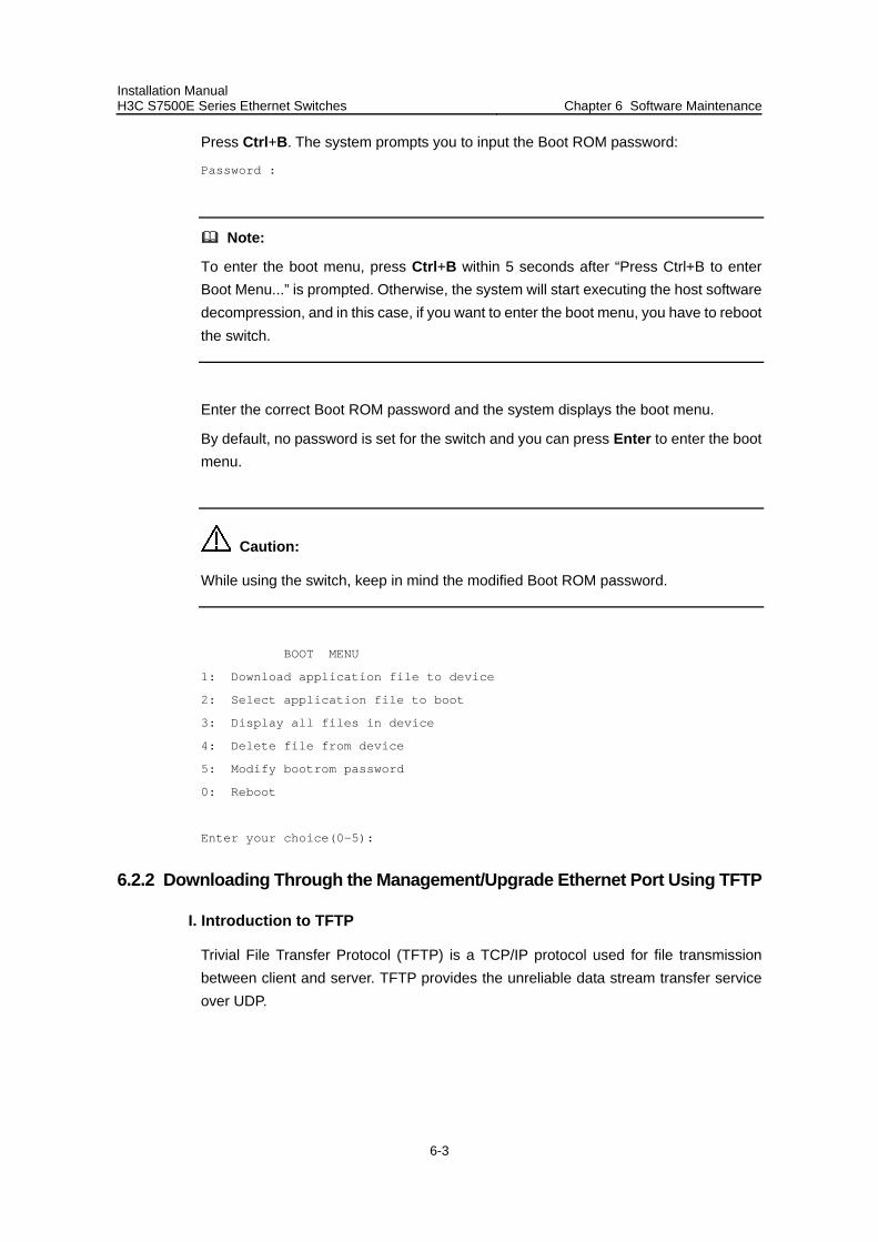
Installation Manual H3C S7500E Series Ethernet Switches Chapter 6 Software Maintenance
6-3
Press Ctrl+B. The system prompts you to input the Boot ROM password:
Password :
Note:
To enter the boot menu, press Ctrl+B within 5 seconds after “Press Ctrl+B to enter Boot Menu...” is prompted. Otherwise, the system will start executing the host software decompression, and in this case, if you want to enter the boot menu, you have to reboot the switch.
Enter the correct Boot ROM password and the system displays the boot menu.
By default, no password is set for the switch and you can press Enter to enter the boot menu.
Caution:
While using the switch, keep in mind the modified Boot ROM password.
BOOT MENU
1: Download application file to device
2: Select application file to boot
3: Display all files in device
4: Delete file from device
5: Modify bootrom password
0: Reboot
Enter your choice(0-5):
6.2.2 Downloading Through the Management/Upgrade Ethernet Port Using TFTP
I. Introduction to TFTP
Trivial File Transfer Protocol (TFTP) is a TCP/IP protocol used for file transmission between client and server. TFTP provides the unreliable data stream transfer service over UDP.
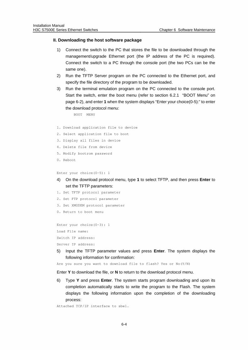
Installation Manual H3C S7500E Series Ethernet Switches Chapter 6 Software Maintenance
6-4
II. Downloading the host software package
1) Connect the switch to the PC that stores the file to be downloaded through the management/upgrade Ethernet port (the IP address of the PC is required). Connect the switch to a PC through the console port (the two PCs can be the same one).
2) Run the TFTP Server program on the PC connected to the Ethernet port, and specify the file directory of the program to be downloaded.
3) Run the terminal emulation program on the PC connected to the console port. Start the switch, enter the boot menu (refer to section 6.2.1 “BOOT Menu” on page 6-2), and enter 1 when the system displays “Enter your choice(0-5):” to enter the download protocol menu:
BOOT MENU
1. Download application file to device
2. Select application file to boot
3. Display all files in device
4. Delete file from device
5. Modify bootrom password
0. Reboot
Enter your choice(0-5): 1
4) On the download protocol menu, type 1 to select TFTP, and then press Enter to set the TFTP parameters:
1. Set TFTP protocol parameter
2. Set FTP protocol parameter
3. Set XMODEM protocol parameter
0. Return to boot menu
Enter your choice(0-3): 1
Load File name:
Switch IP address:
Server IP address:
5) Input the TFTP parameter values and press Enter. The system displays the following information for confirmation:
Are you sure you want to download file to flash? Yes or No(Y/N)
Enter Y to download the file, or N to return to the download protocol menu.
6) Type Y and press Enter. The system starts program downloading and upon its completion automatically starts to write the program to the Flash. The system displays the following information upon the completion of the downloading process:
Attached TCP/IP interface to sbe1.
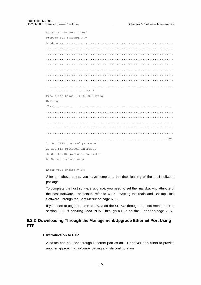
Installation Manual H3C S7500E Series Ethernet Switches Chapter 6 Software Maintenance
6-5
Attaching network interf
Prepare for loading...OK!
Loading...................................................................
..........................................................................
..........................................................................
..........................................................................
..........................................................................
..........................................................................
..........................................................................
..........................................................................
..........................................................................
.......................done!
Free flash Space : 65932288 bytes
Writing
flash.....................................................................
..........................................................................
..........................................................................
..........................................................................
..........................................................................
..........................................................................
.....................................................................done!
1. Set TFTP protocol parameter
2. Set FTP protocol parameter
3. Set XMODEM protocol parameter
0. Return to boot menu
Enter your choice(0-3):
After the above steps, you have completed the downloading of the host software package.
To complete the host software upgrade, you need to set the main/backup attribute of the host software. For details, refer to 6.2.5 “Setting the Main and Backup Host Software Through the Boot Menu” on page 6-13.
If you need to upgrade the Boot ROM on the SRPUs through the boot menu, refer to section 6.2.6 “Updating Boot ROM Through a File on the Flash” on page 6-15.
6.2.3 Downloading Through the Management/Upgrade Ethernet Port Using FTP
I. Introduction to FTP
A switch can be used through Ethernet port as an FTP server or a client to provide another approach to software loading and file configuration.
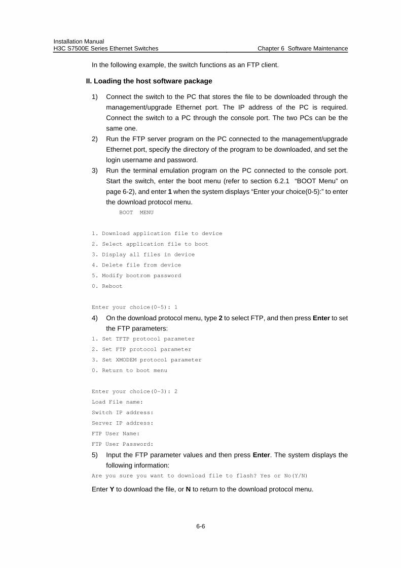
Installation Manual H3C S7500E Series Ethernet Switches Chapter 6 Software Maintenance
6-6
In the following example, the switch functions as an FTP client.
II. Loading the host software package
1) Connect the switch to the PC that stores the file to be downloaded through the management/upgrade Ethernet port. The IP address of the PC is required. Connect the switch to a PC through the console port. The two PCs can be the same one.
2) Run the FTP server program on the PC connected to the management/upgrade Ethernet port, specify the directory of the program to be downloaded, and set the login username and password.
3) Run the terminal emulation program on the PC connected to the console port. Start the switch, enter the boot menu (refer to section 6.2.1 “BOOT Menu” on page 6-2), and enter 1 when the system displays “Enter your choice(0-5):” to enter the download protocol menu.
BOOT MENU
1. Download application file to device
2. Select application file to boot
3. Display all files in device
4. Delete file from device
5. Modify bootrom password
0. Reboot
Enter your choice(0-5): 1
4) On the download protocol menu, type 2 to select FTP, and then press Enter to set the FTP parameters:
1. Set TFTP protocol parameter
2. Set FTP protocol parameter
3. Set XMODEM protocol parameter
0. Return to boot menu
Enter your choice(0-3): 2
Load File name:
Switch IP address:
Server IP address:
FTP User Name:
FTP User Password:
5) Input the FTP parameter values and then press Enter. The system displays the following information:
Are you sure you want to download file to flash? Yes or No(Y/N)
Enter Y to download the file, or N to return to the download protocol menu.
Installation Manual H3C S7500E Series Ethernet Switches Chapter 6 Software Maintenance
6-7
6) Type Y and press Enter. The system starts program downloading and upon its completion automatically starts to write the program to the Flash. The system displays the following information upon the completion of the downloading process:
Attached TCP/IP interface to sbe1.
Attaching network interf
Prepare for loading...OK!
Loading...................................................................
..........................................................................
..........................................................................
..........................................................................
..........................................................................
..........................................................................
..........................................................................
..........................................................................
..........................................................................
.......................done!
Free flash Space : 65932288 bytes
Writing
flash.....................................................................
..........................................................................
..........................................................................
..........................................................................
..........................................................................
..........................................................................
.....................................................................done!
1. Set TFTP protocol parameter
2. Set FTP protocol parameter
3. Set XMODEM protocol parameter
0. Return to boot menu
Enter your choice(0-3):
After the above steps, you have completed the downloading of the host software package.
To complete the host software upgrade, you need to set the main/backup attribute of the host software. For details, refer to 6.2.5 “Setting the Main and Backup Host Software Through the Boot Menu” on page 6-13.
If you need to upgrade the Boot ROM on the SRPUs through the boot menu, refer to section 6.2.6 “Updating Boot ROM Through a File on the Flash” on page 6-15.
Installation Manual H3C S7500E Series Ethernet Switches Chapter 6 Software Maintenance
6-8
6.2.4 Downloading Through the Console Port Using XMODEM
I. Introduction to XMODEM
The XMODEM protocol is a file transfer protocol widely used due to its simplicity and good performance. XMODEM transfers files through the console port, supporting data packets of 128 bytes and 1 KB. With respect to reliability, XMODEM supports checksum, CRC, and error packet retransmission mechanism. Normally, the maximum number of transmission attempts is 10.
XMODEM transmission is completed by the receiving and sending program. The receiving program initiates packet checking method negotiation by sending the negotiation character. After negotiation, the sending program starts packet transmission. Upon the receipt of a complete packet, the receiving program checks it using the negotiated checking method. If the check succeeds, the receiving program sends an acknowledgement character; if the check fails, it sends a negative acknowledgement character. Upon the receipt of an acknowledgement, the sending program continues to send the next packet; upon the receipt of a negative acknowledgement, it retransmits the packet.
Note:
Since it takes a long time to download the host software package through the console port using XMODEM, you may use other alternatives if available.
II. Downloading the host software package
Follow these steps to download the host software package onto the switch:
1) Enter the Boot Menu (refer to section 6.2.1 “BOOT Menu” on page 6-2), and enter 1 when the system displays “Enter your choice(0-5):” to enter the download protocol menu.
BOOT MENU
1. Download application file to device
2. Select application file to boot
3. Display all files in device
4. Delete file from device
5. Modify bootrom password
0. Reboot
Enter your choice(0-5): 1
2) On the download protocol menu, type 3 to select XMODEM and press Enter, and then the system will prompt you to input the name of the file to be downloaded.
1. Set TFTP protocol parameter
2. Set FTP protocol parameter
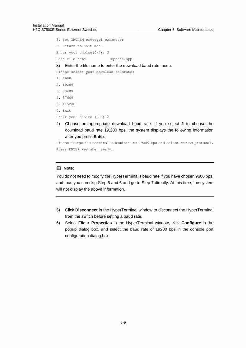
Installation Manual H3C S7500E Series Ethernet Switches Chapter 6 Software Maintenance
6-9
3. Set XMODEM protocol parameter
0. Return to boot menu
Enter your choice(0-4): 3
Load File name :update.app
3) Enter the file name to enter the download baud rate menu: Please select your download baudrate:
1. 9600
2. 19200
3. 38400
4. 57600
5. 115200
0. Exit
Enter your choice (0-5):2
4) Choose an appropriate download baud rate. If you select 2 to choose the download baud rate 19,200 bps, the system displays the following information after you press Enter:
Please change the terminal's baudrate to 19200 bps and select XMODEM protocol.
Press ENTER key when ready.
Note:
You do not need to modify the HyperTerminal’s baud rate if you have chosen 9600 bps, and thus you can skip Step 5 and 6 and go to Step 7 directly. At this time, the system will not display the above information.
5) Click Disconnect in the HyperTerminal window to disconnect the HyperTerminal from the switch before setting a baud rate.
6) Select File > Properties in the HyperTerminal window, click Configure in the popup dialog box, and select the baud rate of 19200 bps in the console port configuration dialog box.

Installation Manual H3C S7500E Series Ethernet Switches Chapter 6 Software Maintenance
6-10
Figure 6-1 Properties dialog box
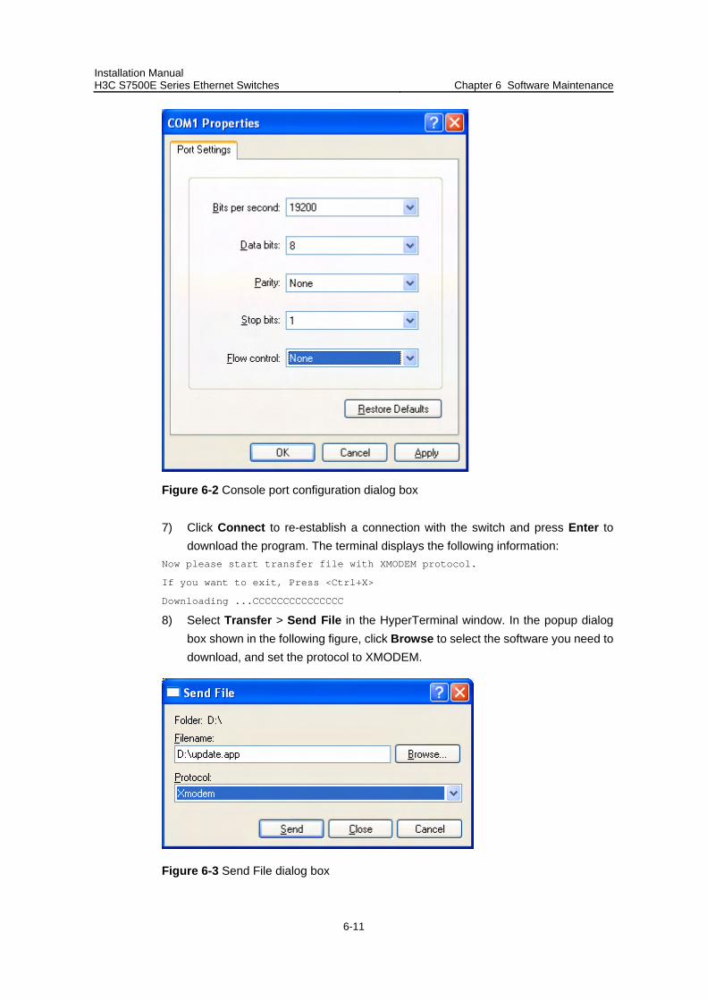
Installation Manual H3C S7500E Series Ethernet Switches Chapter 6 Software Maintenance
6-11
Figure 6-2 Console port configuration dialog box
7) Click Connect to re-establish a connection with the switch and press Enter to download the program. The terminal displays the following information:
Now please start transfer file with XMODEM protocol.
If you want to exit, Press <Ctrl+X>
Downloading ...CCCCCCCCCCCCCCC
8) Select Transfer > Send File in the HyperTerminal window. In the popup dialog box shown in the following figure, click Browse to select the software you need to download, and set the protocol to XMODEM.
Figure 6-3 Send File dialog box
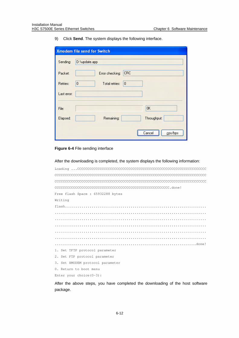
Installation Manual H3C S7500E Series Ethernet Switches Chapter 6 Software Maintenance
6-12
9) Click Send. The system displays the following interface.
Figure 6-4 File sending interface
After the downloading is completed, the system displays the following information:
Loading ...CCCCCCCCCCCCCCCCCCCCCCCCCCCCCCCCCCCCCCCCCCCCCCCCCCCCCCCCCCCCCCC
CCCCCCCCCCCCCCCCCCCCCCCCCCCCCCCCCCCCCCCCCCCCCCCCCCCCCCCCCCCCCCCCCCCCCCCCCC
CCCCCCCCCCCCCCCCCCCCCCCCCCCCCCCCCCCCCCCCCCCCCCCCCCCCCCCCCCCCCCCCCCCCCCCCCC
CCCCCCCCCCCCCCCCCCCCCCCCCCCCCCCCCCCCCCCCCCCCCCCCCCCCCCCC.done!
Free flash Space : 65932288 bytes
Writing
flash.....................................................................
..........................................................................
..........................................................................
..........................................................................
..........................................................................
..........................................................................
.....................................................................done!
1. Set TFTP protocol parameter
2. Set FTP protocol parameter
3. Set XMODEM protocol parameter
0. Return to boot menu
Enter your choice(0-3):
After the above steps, you have completed the downloading of the host software package.
Installation Manual H3C S7500E Series Ethernet Switches Chapter 6 Software Maintenance
6-13
To complete the host software upgrade, you need to set the main/backup attribute of the host software. For details, refer to 6.2.5 “Setting the Main and Backup Host Software Through the Boot Menu” on page 6-13.
If you need to upgrade the Boot ROM on the SRPUs through the boot menu, refer to section 6.2.6 “Updating Boot ROM Through a File on the Flash” on page 6-15.
Note:
After the system reboots, you need to change the baud rate of the HyperTerminal back to 9600 bps as described in Steps 5 and 6. You need not to change the baud rate if you have chosen 9600 bps for download.
6.2.5 Setting the Main and Backup Host Software Through the Boot Menu
The S7500E series support dual image booting. Usually the switch boots with the main image (namely, the main boot file), but uses the backup image (namely, the backup boot file) when the main image is in error.
For the setting of the main and backup host software through command lines, refer to section 6.4.1 I. 3)“Set the main and backup boot files.” on page 6-20. The following introduces the setting of dual image through the boot menu.
1) Enter the boot menu. BOOT MENU
1. Download application file to device
2. Select application file to boot
3. Display all files in device
4. Delete file from device
5. Modify bootrom password
0. Reboot
Enter your choice(0-5): 2
Select 2 and press Enter.
File Number File Size(bytes) File Name
========================================================
1. 4 snmpboots
2. 1972 SWITCH100.cfg
3. 1012 taskswitch.log
4. 631736 Btm105.app
5. 199696 8241btm.app
6. 6048565 SWITCH200.app
7(*). 5639172 SWITCH000.app
8(-). 203460 SWITCH100.app
Installation Manual H3C S7500E Series Ethernet Switches Chapter 6 Software Maintenance
6-14
Flash Free Space : 21444608 bytes
The current application file is :SWITCH000.app
The backup application file is : SWITCH100.app
The system displays all files on the Flash, wherein the file number with an asterisk (*) is the main boot file and the one with a hyphen (-) is the backup boot file.
2) Re-configure the main and backup boot files. Set the main boot file.
Enter the sequence number of the desired main boot file when the terminal displays the following information:
Please input the primary application file number to boot :8
Press Enter and the terminal displays the name of the main boot file you have chosen. Type Y to confirm it, or N to reset the main boot file.
The primary file you selected is SWITCH100.app, are you sure? Yes or No(Y/N):Y
If you type Y, the terminal displays the following information:
On reboot, SWITCH100.app will become the default primary application file to
boot!
This means the main boot file has been set successfully.
Set the backup boot file.
You can set the backup boot file in a similar way you set the main boot file. The terminal displays the following information:
Please input the backup application file number :6
The file you selected is SWITCH200.app, are you sure? Yes or No(Y/N)y
On reboot,SWITCH200.app will become the backup application file to boot!
3) Decide whether to run the main boot file immediately. If you type Y and press Enter, the system begins to reboot.
Do you want to run SWITCH100.app now?Yes or No(Y/N)?Y
Auto-booting....................
One of the following cases may occur when the system is rebooting:
The main boot file is correct and the system boots with the main boot file. An error occurs to the main boot file, so the system boots with the backup boot file. An error occurs to both the main and backup files, so the system randomly
chooses an application file for booting. If the system fails to boot with the randomly-chosen application file, it supposes
that the file system is unavailable or no correct boot file is available and thus stops choosing a boot file.
Installation Manual H3C S7500E Series Ethernet Switches Chapter 6 Software Maintenance
6-15
Note:
If you do not specify the backup boot file but the main boot file only, the system boots with the main boot file. If the main boot file has an error, the system randomly chooses an application file for booting.
If you do not specify the main boot file but the backup boot file only, the system boots with the backup boot file.
If you specify neither the main boot file nor the backup boot file, the system randomly chooses an application file for booting.
6.2.6 Updating Boot ROM Through a File on the Flash
1) Download the host software package containing the Boot ROM program onto the switch.
Note:
You can download the host software through the Boot menu or command lines.
2) Enter the Boot menu. After the system prompts “Enter your choice(0-5):”, press Ctrl+U and then press Enter to enter the Boot ROM update menu.
bootrom update menu:
1. Set TFTP protocol parameter
2. Set FTP protocol parameter
3. Set XMODEM protocol parameter
4. Update through file in device
0. Return to boot menu
Enter your choice(0-4):
3) Select 4 from the Boot ROM update menu to upgrade the Boot ROM program through a file on the Flash memory. Press Enter and the system displays the following information:
Flash:/
File Number File Size(bytes) File Name
========================================================
0(*). 23250494 update.app
1. 3443 config.cfg
Flash Free Space : 41804800 bytes
The current application file is: update.app
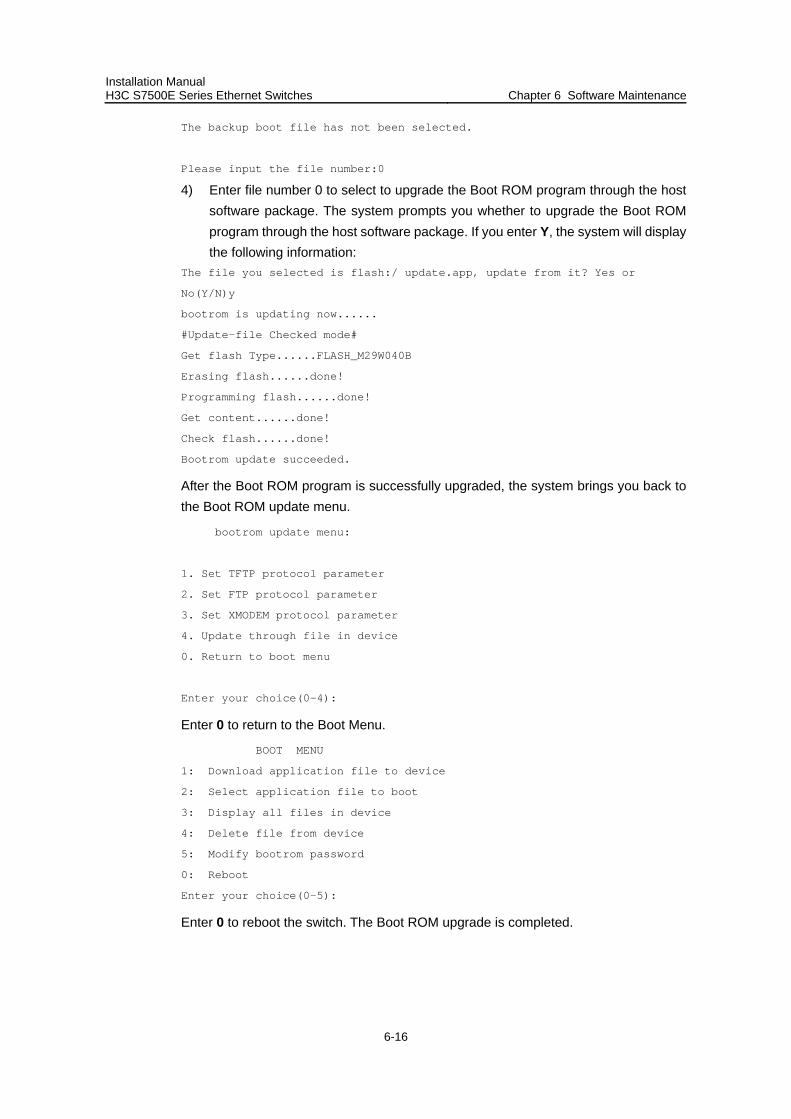
Installation Manual H3C S7500E Series Ethernet Switches Chapter 6 Software Maintenance
6-16
The backup boot file has not been selected.
Please input the file number:0
4) Enter file number 0 to select to upgrade the Boot ROM program through the host software package. The system prompts you whether to upgrade the Boot ROM program through the host software package. If you enter Y, the system will display the following information:
The file you selected is flash:/ update.app, update from it? Yes or
No(Y/N)y
bootrom is updating now......
#Update-file Checked mode#
Get flash Type......FLASH_M29W040B
Erasing flash......done!
Programming flash......done!
Get content......done!
Check flash......done!
Bootrom update succeeded.
After the Boot ROM program is successfully upgraded, the system brings you back to the Boot ROM update menu.
bootrom update menu:
1. Set TFTP protocol parameter
2. Set FTP protocol parameter
3. Set XMODEM protocol parameter
4. Update through file in device
0. Return to boot menu
Enter your choice(0-4):
Enter 0 to return to the Boot Menu.
BOOT MENU
1: Download application file to device
2: Select application file to boot
3: Display all files in device
4: Delete file from device
5: Modify bootrom password
0: Reboot
Enter your choice(0-5):
Enter 0 to reboot the switch. The Boot ROM upgrade is completed.
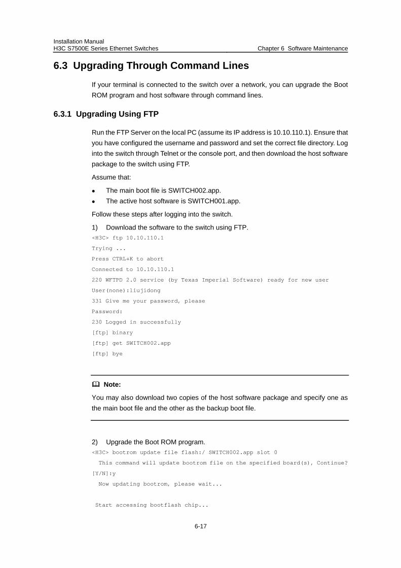
Installation Manual H3C S7500E Series Ethernet Switches Chapter 6 Software Maintenance
6-17
6.3 Upgrading Through Command Lines
If your terminal is connected to the switch over a network, you can upgrade the Boot ROM program and host software through command lines.
6.3.1 Upgrading Using FTP
Run the FTP Server on the local PC (assume its IP address is 10.10.110.1). Ensure that you have configured the username and password and set the correct file directory. Log into the switch through Telnet or the console port, and then download the host software package to the switch using FTP.
Assume that:
The main boot file is SWITCH002.app. The active host software is SWITCH001.app.
Follow these steps after logging into the switch.
1) Download the software to the switch using FTP. <H3C> ftp 10.10.110.1
Trying ...
Press CTRL+K to abort
Connected to 10.10.110.1
220 WFTPD 2.0 service (by Texas Imperial Software) ready for new user
User(none):liujidong
331 Give me your password, please
Password:
230 Logged in successfully
[ftp] binary
[ftp] get SWITCH002.app
[ftp] bye
Note:
You may also download two copies of the host software package and specify one as the main boot file and the other as the backup boot file.
2) Upgrade the Boot ROM program. <H3C> bootrom update file flash:/ SWITCH002.app slot 0
This command will update bootrom file on the specified board(s), Continue?
[Y/N]:y
Now updating bootrom, please wait...
Start accessing bootflash chip...
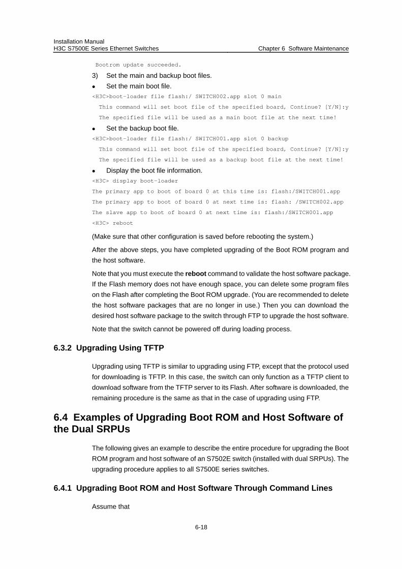
Installation Manual H3C S7500E Series Ethernet Switches Chapter 6 Software Maintenance
6-18
Bootrom update succeeded.
3) Set the main and backup boot files. Set the main boot file. <H3C>boot-loader file flash:/ SWITCH002.app slot 0 main
This command will set boot file of the specified board, Continue? [Y/N]:y
The specified file will be used as a main boot file at the next time!
Set the backup boot file. <H3C>boot-loader file flash:/ SWITCH001.app slot 0 backup
This command will set boot file of the specified board, Continue? [Y/N]:y
The specified file will be used as a backup boot file at the next time!
Display the boot file information. <H3C> display boot-loader
The primary app to boot of board 0 at this time is: flash:/SWITCH001.app
The primary app to boot of board 0 at next time is: flash: /SWITCH002.app
The slave app to boot of board 0 at next time is: flash:/SWITCH001.app
<H3C> reboot
(Make sure that other configuration is saved before rebooting the system.)
After the above steps, you have completed upgrading of the Boot ROM program and the host software.
Note that you must execute the reboot command to validate the host software package. If the Flash memory does not have enough space, you can delete some program files on the Flash after completing the Boot ROM upgrade. (You are recommended to delete the host software packages that are no longer in use.) Then you can download the desired host software package to the switch through FTP to upgrade the host software.
Note that the switch cannot be powered off during loading process.
6.3.2 Upgrading Using TFTP
Upgrading using TFTP is similar to upgrading using FTP, except that the protocol used for downloading is TFTP. In this case, the switch can only function as a TFTP client to download software from the TFTP server to its Flash. After software is downloaded, the remaining procedure is the same as that in the case of upgrading using FTP.
6.4 Examples of Upgrading Boot ROM and Host Software of the Dual SRPUs
The following gives an example to describe the entire procedure for upgrading the Boot ROM program and host software of an S7502E switch (installed with dual SRPUs). The upgrading procedure applies to all S7500E series switches.
6.4.1 Upgrading Boot ROM and Host Software Through Command Lines
Assume that
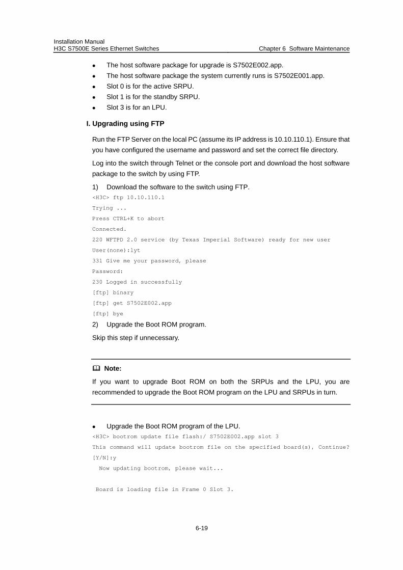
Installation Manual H3C S7500E Series Ethernet Switches Chapter 6 Software Maintenance
6-19
The host software package for upgrade is S7502E002.app. The host software package the system currently runs is S7502E001.app. Slot 0 is for the active SRPU. Slot 1 is for the standby SRPU. Slot 3 is for an LPU.
I. Upgrading using FTP
Run the FTP Server on the local PC (assume its IP address is 10.10.110.1). Ensure that you have configured the username and password and set the correct file directory.
Log into the switch through Telnet or the console port and download the host software package to the switch by using FTP.
1) Download the software to the switch using FTP. <H3C> ftp 10.10.110.1
Trying ...
Press CTRL+K to abort
Connected.
220 WFTPD 2.0 service (by Texas Imperial Software) ready for new user
User(none):lyt
331 Give me your password, please
Password:
230 Logged in successfully
[ftp] binary
[ftp] get S7502E002.app
[ftp] bye
2) Upgrade the Boot ROM program.
Skip this step if unnecessary.
Note:
If you want to upgrade Boot ROM on both the SRPUs and the LPU, you are recommended to upgrade the Boot ROM program on the LPU and SRPUs in turn.
Upgrade the Boot ROM program of the LPU. <H3C> bootrom update file flash:/ S7502E002.app slot 3
This command will update bootrom file on the specified board(s), Continue?
[Y/N]:y
Now updating bootrom, please wait...
Board is loading file in Frame 0 Slot 3.
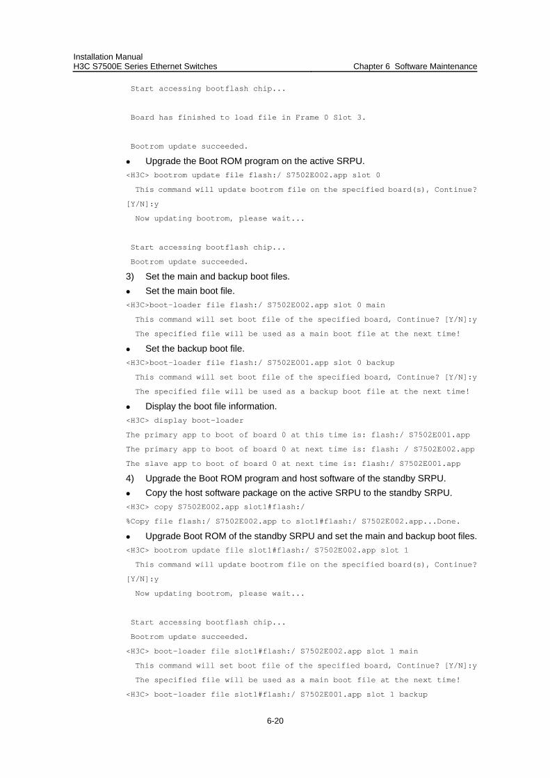
Installation Manual H3C S7500E Series Ethernet Switches Chapter 6 Software Maintenance
6-20
Start accessing bootflash chip...
Board has finished to load file in Frame 0 Slot 3.
Bootrom update succeeded.
Upgrade the Boot ROM program on the active SRPU. <H3C> bootrom update file flash:/ S7502E002.app slot 0
This command will update bootrom file on the specified board(s), Continue?
[Y/N]:y
Now updating bootrom, please wait...
Start accessing bootflash chip...
Bootrom update succeeded.
3) Set the main and backup boot files. Set the main boot file. <H3C>boot-loader file flash:/ S7502E002.app slot 0 main
This command will set boot file of the specified board, Continue? [Y/N]:y
The specified file will be used as a main boot file at the next time!
Set the backup boot file. <H3C>boot-loader file flash:/ S7502E001.app slot 0 backup
This command will set boot file of the specified board, Continue? [Y/N]:y
The specified file will be used as a backup boot file at the next time!
Display the boot file information. <H3C> display boot-loader
The primary app to boot of board 0 at this time is: flash:/ S7502E001.app
The primary app to boot of board 0 at next time is: flash: / S7502E002.app
The slave app to boot of board 0 at next time is: flash:/ S7502E001.app
4) Upgrade the Boot ROM program and host software of the standby SRPU. Copy the host software package on the active SRPU to the standby SRPU. <H3C> copy S7502E002.app slot1#flash:/
%Copy file flash:/ S7502E002.app to slot1#flash:/ S7502E002.app...Done.
Upgrade Boot ROM of the standby SRPU and set the main and backup boot files. <H3C> bootrom update file slot1#flash:/ S7502E002.app slot 1
This command will update bootrom file on the specified board(s), Continue?
[Y/N]:y
Now updating bootrom, please wait...
Start accessing bootflash chip...
Bootrom update succeeded.
<H3C> boot-loader file slot1#flash:/ S7502E002.app slot 1 main
This command will set boot file of the specified board, Continue? [Y/N]:y
The specified file will be used as a main boot file at the next time!
<H3C> boot-loader file slot1#flash:/ S7502E001.app slot 1 backup
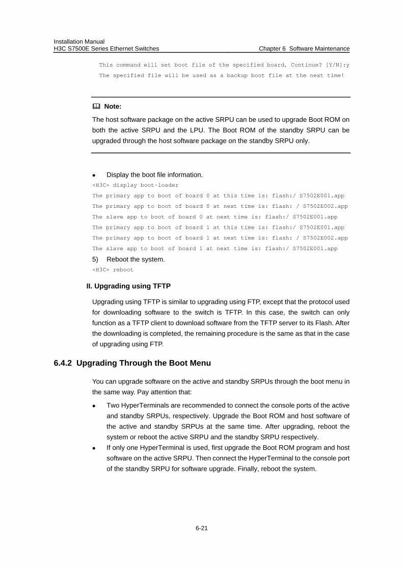
Installation Manual H3C S7500E Series Ethernet Switches Chapter 6 Software Maintenance
6-21
This command will set boot file of the specified board, Continue? [Y/N]:y
The specified file will be used as a backup boot file at the next time!
Note:
The host software package on the active SRPU can be used to upgrade Boot ROM on both the active SRPU and the LPU. The Boot ROM of the standby SRPU can be upgraded through the host software package on the standby SRPU only.
Display the boot file information. <H3C> display boot-loader
The primary app to boot of board 0 at this time is: flash:/ S7502E001.app
The primary app to boot of board 0 at next time is: flash: / S7502E002.app
The slave app to boot of board 0 at next time is: flash:/ S7502E001.app
The primary app to boot of board 1 at this time is: flash:/ S7502E001.app
The primary app to boot of board 1 at next time is: flash: / S7502E002.app
The slave app to boot of board 1 at next time is: flash:/ S7502E001.app
5) Reboot the system. <H3C> reboot
II. Upgrading using TFTP
Upgrading using TFTP is similar to upgrading using FTP, except that the protocol used for downloading software to the switch is TFTP. In this case, the switch can only function as a TFTP client to download software from the TFTP server to its Flash. After the downloading is completed, the remaining procedure is the same as that in the case of upgrading using FTP.
6.4.2 Upgrading Through the Boot Menu
You can upgrade software on the active and standby SRPUs through the boot menu in the same way. Pay attention that:
Two HyperTerminals are recommended to connect the console ports of the active and standby SRPUs, respectively. Upgrade the Boot ROM and host software of the active and standby SRPUs at the same time. After upgrading, reboot the system or reboot the active SRPU and the standby SRPU respectively.
If only one HyperTerminal is used, first upgrade the Boot ROM program and host software on the active SRPU. Then connect the HyperTerminal to the console port of the standby SRPU for software upgrade. Finally, reboot the system.
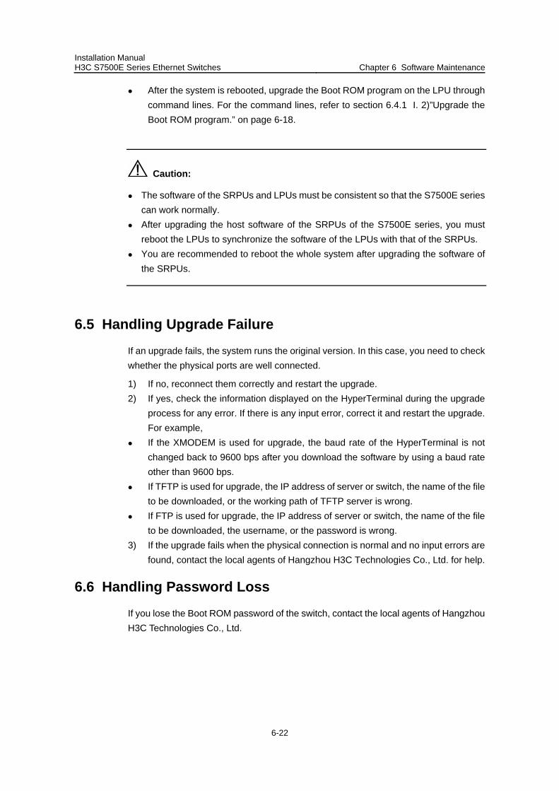
Installation Manual H3C S7500E Series Ethernet Switches Chapter 6 Software Maintenance
6-22
After the system is rebooted, upgrade the Boot ROM program on the LPU through command lines. For the command lines, refer to section 6.4.1 I. 2)”Upgrade the Boot ROM program.” on page 6-18.
Caution:
The software of the SRPUs and LPUs must be consistent so that the S7500E series can work normally.
After upgrading the host software of the SRPUs of the S7500E series, you must reboot the LPUs to synchronize the software of the LPUs with that of the SRPUs.
You are recommended to reboot the whole system after upgrading the software of the SRPUs.
6.5 Handling Upgrade Failure
If an upgrade fails, the system runs the original version. In this case, you need to check whether the physical ports are well connected.
1) If no, reconnect them correctly and restart the upgrade. 2) If yes, check the information displayed on the HyperTerminal during the upgrade
process for any error. If there is any input error, correct it and restart the upgrade. For example,
If the XMODEM is used for upgrade, the baud rate of the HyperTerminal is not changed back to 9600 bps after you download the software by using a baud rate other than 9600 bps.
If TFTP is used for upgrade, the IP address of server or switch, the name of the file to be downloaded, or the working path of TFTP server is wrong.
If FTP is used for upgrade, the IP address of server or switch, the name of the file to be downloaded, the username, or the password is wrong.
3) If the upgrade fails when the physical connection is normal and no input errors are found, contact the local agents of Hangzhou H3C Technologies Co., Ltd. for help.
6.6 Handling Password Loss
If you lose the Boot ROM password of the switch, contact the local agents of Hangzhou H3C Technologies Co., Ltd.
Installation Manual H3C S7500E Series Ethernet Switches Table of Contents
i
Table of Contents
Chapter 7 Troubleshooting .......................................................................................................... 7-1 7.1 Troubleshooting the Configuration System ....................................................................... 7-1
7.1.1 No Display on the Terminal..................................................................................... 7-1 7.1.2 Illegible Characters on the Terminal ....................................................................... 7-2
7.2 Troubleshooting Power Modules ....................................................................................... 7-2 7.2.1 Troubleshooting the PSR320-A and the PSR320-D............................................... 7-2 7.2.2 Troubleshooting the PSR650-A and the PSR650-D............................................... 7-2 7.2.3 Troubleshooting PSR1400-A .................................................................................. 7-2 7.2.4 Troubleshooting PSR1400-D .................................................................................. 7-3 7.2.5 Troubleshooting PSR2800-ACV ............................................................................. 7-5
7.3 Troubleshooting Fans ........................................................................................................ 7-5 7.4 Troubleshooting LPUs ....................................................................................................... 7-5
Installation Manual H3C S7500E Series Ethernet Switches Chapter 7 Troubleshooting
7-1
Chapter 7 Troubleshooting
Although the S7500E series have passed the comprehensive and strict test before delivery, faults may occur due to improper installation. This chapter describes how to handle faults caused by improper installation.
On the SRPU of the S7500E series, you can find the status LEDs of LPUs, power modules, and fans. You can check these status LEDs to locate faults.
Note:
The LEDs on the standby SRPU of the S7500E series are always OFF except the SRPU LED. The SRPU LED on the standby SRPU is in the same state as that on the active SRPU. Thus, you need not consider the LEDs on the standby SRPU when troubleshooting power modules, fans, or LPUs.
7.1 Troubleshooting the Configuration System
After the switch is powered on and the system is normal, the booting information will be displayed on the configuration terminal. If the configuration system has failed, the configuration terminal may display illegible characters or nothing at all.
7.1.1 No Display on the Terminal
After the switch is powered on, if no information is displayed on the terminal, check if:
The power system works normally. SRPU works normally. The console cable is connected to the console port of the SRPU.
If no problem is found after the above check, check if:
The serial port connected to the console cable is wrong. (The port in use is not the one set on the terminal.)
The configuration of parameters on the terminal is wrong.
Correct parameter configuration is listed as follows:
–Bits per second: 9600
–Data bits: 8
–Parity: None
–Stop bits: 1
Installation Manual H3C S7500E Series Ethernet Switches Chapter 7 Troubleshooting
7-2
–Flow control: None
–Terminal emulation mode: VT100
Something is wrong with the console cable.
7.1.2 Illegible Characters on the Terminal
If the configuration terminal displays illegible characters, configuration of parameters on the terminal might be incorrect. In this case, check the configuration according to the correct one listed in section 7.1.1 “No Display on the Terminal” on page 7-1.
7.2 Troubleshooting Power Modules
7.2.1 Troubleshooting the PSR320-A and the PSR320-D
The power modules PSR320-A and PSR320-D each have only one power LED.
1) When the power LED is in green, the power module works normally. 2) When the power LED is in red, the power module is faulty. It is possible that
The power output is abnormal. The power module is overheated. The power module fan is faulty.
3) When the power LED is OFF, the power supply of the system is faulty.
In this case, check whether:
The power switch is turned on. The power cable is properly connected. The voltage is correct.
On the SRPUs, there are also LEDs indicating the working status of the power modules. For details, refer to related description about the power LEDs in Chapter 1 “Product Overview”.
7.2.2 Troubleshooting the PSR650-A and the PSR650-D
Refer to section 7.2.1 “Troubleshooting the PSR650-A and the PSR650-D” on page 7-2.
7.2.3 Troubleshooting PSR1400-A
The power module PSR1400-A has three status LEDs, which indicate the input and output statuses of the power module and the working status of the power module fan, respectively.
Table 7-1 describes the colors and working status of the three LEDs in different cases.
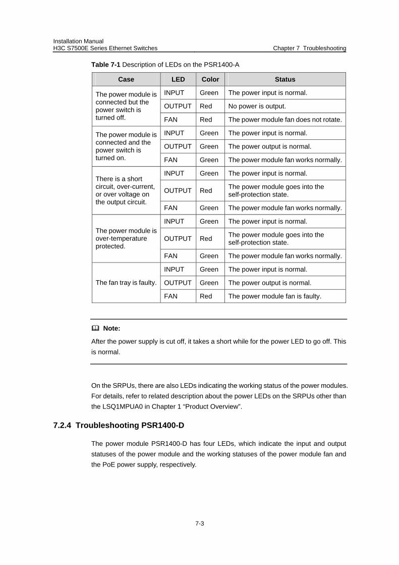
Installation Manual H3C S7500E Series Ethernet Switches Chapter 7 Troubleshooting
7-3
Table 7-1 Description of LEDs on the PSR1400-A
Case LED Color Status
INPUT Green The power input is normal.
OUTPUT Red No power is output.
The power module is connected but the power switch is turned off. FAN Red The power module fan does not rotate.
INPUT Green The power input is normal.
OUTPUT Green The power output is normal.
The power module is connected and the power switch is turned on. FAN Green The power module fan works normally.
INPUT Green The power input is normal.
OUTPUT Red The power module goes into the self-protection state.
There is a short circuit, over-current, or over voltage on the output circuit.
FAN Green The power module fan works normally.
INPUT Green The power input is normal.
OUTPUT Red The power module goes into the self-protection state.
The power module is over-temperature protected.
FAN Green The power module fan works normally.
INPUT Green The power input is normal.
OUTPUT Green The power output is normal. The fan tray is faulty.
FAN Red The power module fan is faulty.
Note:
After the power supply is cut off, it takes a short while for the power LED to go off. This is normal.
On the SRPUs, there are also LEDs indicating the working status of the power modules. For details, refer to related description about the power LEDs on the SRPUs other than the LSQ1MPUA0 in Chapter 1 “Product Overview”.
7.2.4 Troubleshooting PSR1400-D
The power module PSR1400-D has four LEDs, which indicate the input and output statuses of the power module and the working statuses of the power module fan and the PoE power supply, respectively.
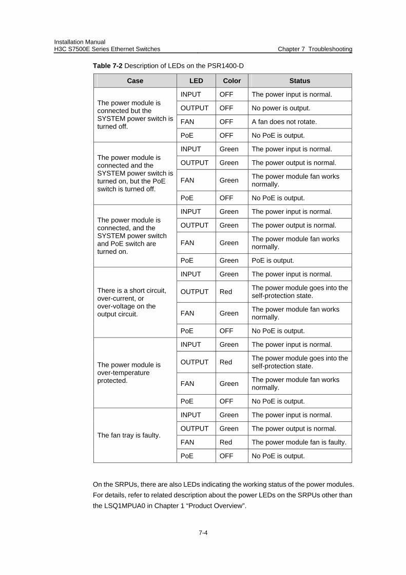
Installation Manual H3C S7500E Series Ethernet Switches Chapter 7 Troubleshooting
7-4
Table 7-2 Description of LEDs on the PSR1400-D
Case LED Color Status
INPUT OFF The power input is normal.
OUTPUT OFF No power is output.
FAN OFF A fan does not rotate.
The power module is connected but the SYSTEM power switch is turned off.
PoE OFF No PoE is output.
INPUT Green The power input is normal.
OUTPUT Green The power output is normal.
FAN Green The power module fan works normally.
The power module is connected and the SYSTEM power switch is turned on, but the PoE switch is turned off.
PoE OFF No PoE is output.
INPUT Green The power input is normal.
OUTPUT Green The power output is normal.
FAN Green The power module fan works normally.
The power module is connected, and the SYSTEM power switch and PoE switch are turned on.
PoE Green PoE is output.
INPUT Green The power input is normal.
OUTPUT Red The power module goes into the self-protection state.
FAN Green The power module fan works normally.
There is a short circuit, over-current, or over-voltage on the output circuit.
PoE OFF No PoE is output.
INPUT Green The power input is normal.
OUTPUT Red The power module goes into the self-protection state.
FAN Green The power module fan works normally.
The power module is over-temperature protected.
PoE OFF No PoE is output.
INPUT Green The power input is normal.
OUTPUT Green The power output is normal.
FAN Red The power module fan is faulty.The fan tray is faulty.
PoE OFF No PoE is output.
On the SRPUs, there are also LEDs indicating the working status of the power modules. For details, refer to related description about the power LEDs on the SRPUs other than the LSQ1MPUA0 in Chapter 1 “Product Overview”.
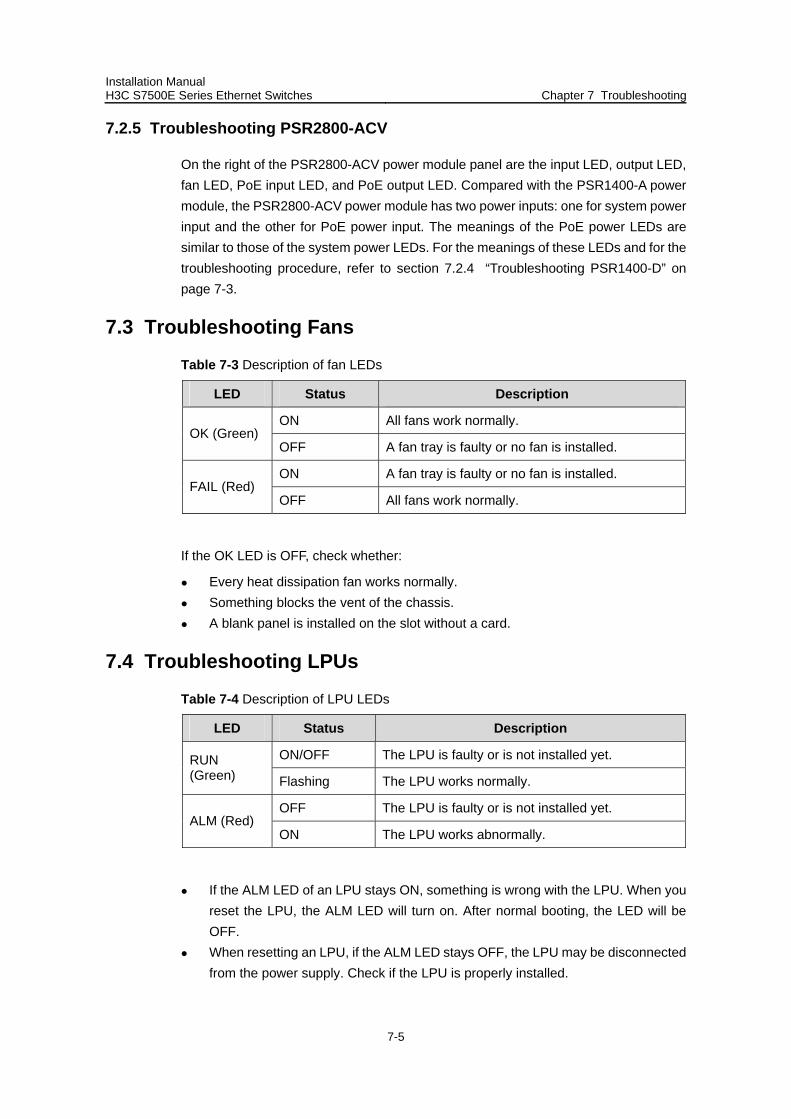
Installation Manual H3C S7500E Series Ethernet Switches Chapter 7 Troubleshooting
7-5
7.2.5 Troubleshooting PSR2800-ACV
On the right of the PSR2800-ACV power module panel are the input LED, output LED, fan LED, PoE input LED, and PoE output LED. Compared with the PSR1400-A power module, the PSR2800-ACV power module has two power inputs: one for system power input and the other for PoE power input. The meanings of the PoE power LEDs are similar to those of the system power LEDs. For the meanings of these LEDs and for the troubleshooting procedure, refer to section 7.2.4 “Troubleshooting PSR1400-D” on page 7-3.
7.3 Troubleshooting Fans
Table 7-3 Description of fan LEDs
LED Status Description
ON All fans work normally. OK (Green)
OFF A fan tray is faulty or no fan is installed.
ON A fan tray is faulty or no fan is installed. FAIL (Red)
OFF All fans work normally.
If the OK LED is OFF, check whether:
Every heat dissipation fan works normally. Something blocks the vent of the chassis. A blank panel is installed on the slot without a card.
7.4 Troubleshooting LPUs
Table 7-4 Description of LPU LEDs
LED Status Description
ON/OFF The LPU is faulty or is not installed yet. RUN (Green) Flashing The LPU works normally.
OFF The LPU is faulty or is not installed yet. ALM (Red)
ON The LPU works abnormally.
If the ALM LED of an LPU stays ON, something is wrong with the LPU. When you reset the LPU, the ALM LED will turn on. After normal booting, the LED will be OFF.
When resetting an LPU, if the ALM LED stays OFF, the LPU may be disconnected from the power supply. Check if the LPU is properly installed.

Installation Manual H3C S7500E Series Ethernet Switches Table of Contents
i
Table of Contents
Appendix A List of Pluggable Modules.......................................................................................A-1 A.1 10G XFP Modules .............................................................................................................A-1 A.2 Gigabit SFP Modules ........................................................................................................A-1 A.3 100 Mbps SFP Modules ....................................................................................................A-2 A.4 Pluggable Modules for EPON Interfaces ..........................................................................A-3
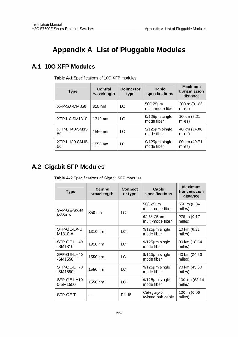
Installation Manual H3C S7500E Series Ethernet Switches Appendix A List of Pluggable Modules
A-1
Appendix A List of Pluggable Modules
A.1 10G XFP Modules
Table A-1 Specifications of 10G XFP modules
Type Central wavelength
Connector type
Cable specifications
Maximum transmission
distance
XFP-SX-MM850 850 nm LC 50/125µm multi-mode fiber
300 m (0.186 miles)
XFP-LX-SM1310 1310 nm LC 9/125µm single mode fiber
10 km (6.21 miles)
XFP-LH40-SM1550 1550 nm LC 9/125µm single
mode fiber 40 km (24.86 miles)
XFP-LH80-SM1550 1550 nm LC 9/125µm single
mode fiber 80 km (49.71 miles)
A.2 Gigabit SFP Modules
Table A-2 Specifications of Gigabit SFP modules
Type Central wavelength
Connector type
Cable specifications
Maximum transmission
distance
50/125µm multi-mode fiber
550 m (0.34 miles) SFP-GE-SX-M
M850-A 850 nm LC 62.5/125µm multi-mode fiber
275 m (0.17 miles)
SFP-GE-LX-SM1310-A 1310 nm LC 9/125µm single
mode fiber 10 km (6.21 miles)
SFP-GE-LH40-SM1310 1310 nm LC 9/125µm single
mode fiber 30 km (18.64 miles)
SFP-GE-LH40-SM1550 1550 nm LC 9/125µm single
mode fiber 40 km (24.86 miles)
SFP-GE-LH70-SM1550 1550 nm LC 9/125µm single
mode fiber 70 km (43.50 miles)
SFP-GE-LH100-SM1550 1550 nm LC 9/125µm single
mode fiber 100 km (62.14 miles)
SFP-GE-T — RJ-45 Category-5 twisted pair cable
100 m (0.06 miles)
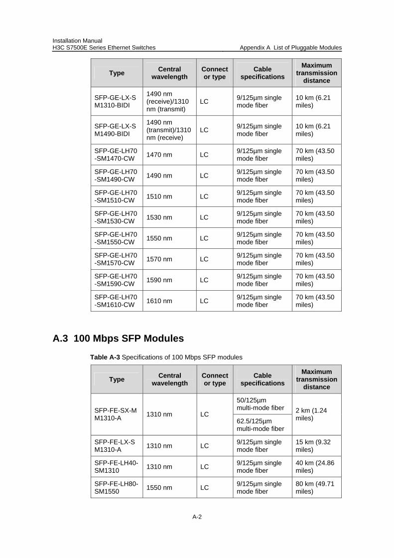
Installation Manual H3C S7500E Series Ethernet Switches Appendix A List of Pluggable Modules
A-2
Type Central wavelength
Connector type
Cable specifications
Maximum transmission
distance
SFP-GE-LX-SM1310-BIDI
1490 nm (receive)/1310 nm (transmit)
LC 9/125µm single mode fiber
10 km (6.21 miles)
SFP-GE-LX-SM1490-BIDI
1490 nm (transmit)/1310 nm (receive)
LC 9/125µm single mode fiber
10 km (6.21 miles)
SFP-GE-LH70-SM1470-CW 1470 nm LC 9/125µm single
mode fiber 70 km (43.50 miles)
SFP-GE-LH70-SM1490-CW 1490 nm LC 9/125µm single
mode fiber 70 km (43.50 miles)
SFP-GE-LH70-SM1510-CW 1510 nm LC 9/125µm single
mode fiber 70 km (43.50 miles)
SFP-GE-LH70-SM1530-CW 1530 nm LC 9/125µm single
mode fiber 70 km (43.50 miles)
SFP-GE-LH70-SM1550-CW 1550 nm LC 9/125µm single
mode fiber 70 km (43.50 miles)
SFP-GE-LH70-SM1570-CW 1570 nm LC 9/125µm single
mode fiber 70 km (43.50 miles)
SFP-GE-LH70-SM1590-CW 1590 nm LC 9/125µm single
mode fiber 70 km (43.50 miles)
SFP-GE-LH70-SM1610-CW 1610 nm LC 9/125µm single
mode fiber 70 km (43.50 miles)
A.3 100 Mbps SFP Modules
Table A-3 Specifications of 100 Mbps SFP modules
Type Central wavelength
Connector type
Cable specifications
Maximum transmission
distance
50/125µm multi-mode fiber SFP-FE-SX-M
M1310-A 1310 nm LC 62.5/125µm multi-mode fiber
2 km (1.24 miles)
SFP-FE-LX-SM1310-A 1310 nm LC 9/125µm single
mode fiber 15 km (9.32 miles)
SFP-FE-LH40-SM1310 1310 nm LC 9/125µm single
mode fiber 40 km (24.86 miles)
SFP-FE-LH80-SM1550 1550 nm LC 9/125µm single
mode fiber 80 km (49.71 miles)
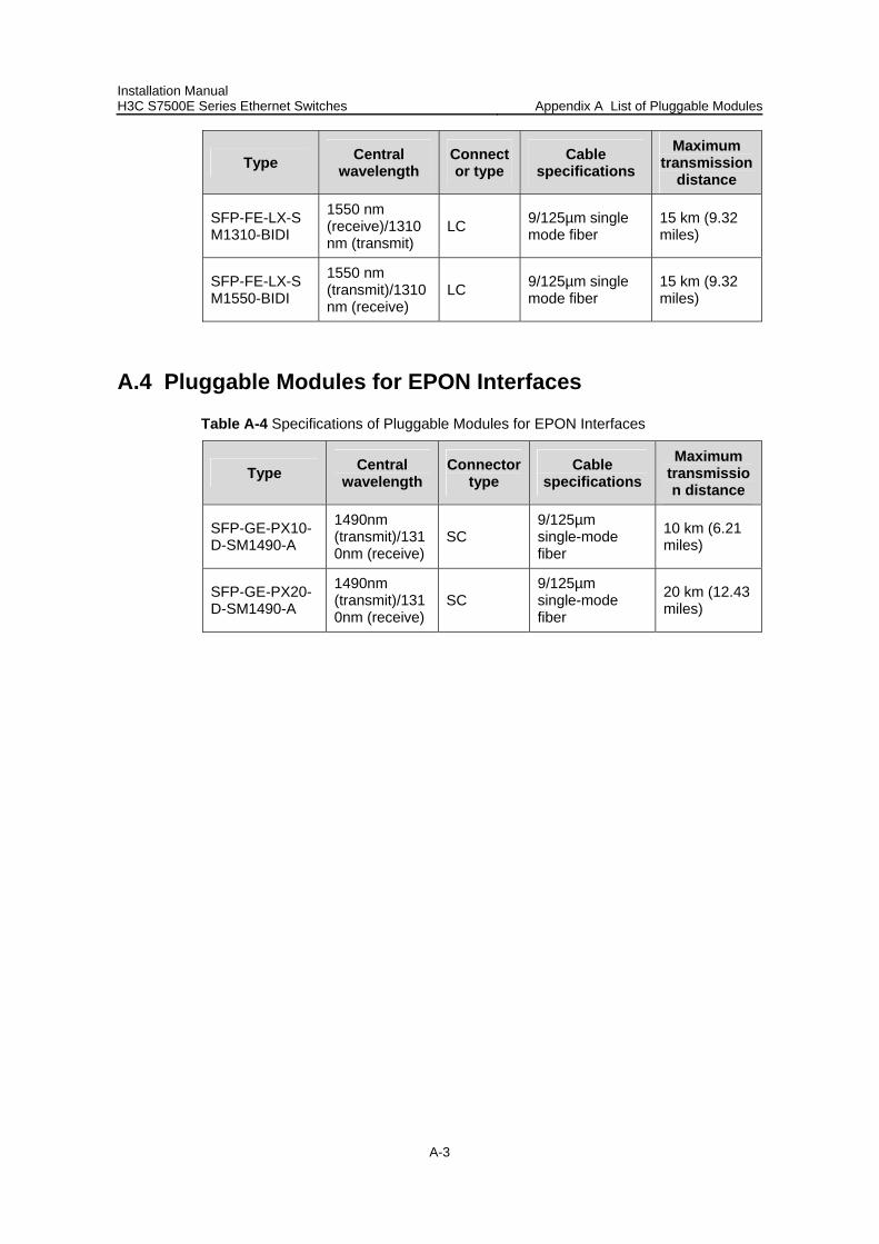
Installation Manual H3C S7500E Series Ethernet Switches Appendix A List of Pluggable Modules
A-3
Type Central wavelength
Connector type
Cable specifications
Maximum transmission
distance
SFP-FE-LX-SM1310-BIDI
1550 nm (receive)/1310 nm (transmit)
LC 9/125µm single mode fiber
15 km (9.32 miles)
SFP-FE-LX-SM1550-BIDI
1550 nm (transmit)/1310 nm (receive)
LC 9/125µm single mode fiber
15 km (9.32 miles)
A.4 Pluggable Modules for EPON Interfaces
Table A-4 Specifications of Pluggable Modules for EPON Interfaces
Type Central wavelength
Connector type
Cable specifications
Maximum transmission distance
SFP-GE-PX10-D-SM1490-A
1490nm (transmit)/1310nm (receive)
SC 9/125µm single-mode fiber
10 km (6.21 miles)
SFP-GE-PX20-D-SM1490-A
1490nm (transmit)/1310nm (receive)
SC 9/125µm single-mode fiber
20 km (12.43 miles)

Installation Manual H3C S7500E Series Ethernet Switches Table of Contents
i
Table of Contents
Chapter B AC Power Cables Used in Different Countries or Regions.....................................B-1 B.1 10A AC Power Cables Used in Different Countries or Regions........................................B-1 B.2 16A AC Power Cables Used in Different Countries or Regions........................................B-6
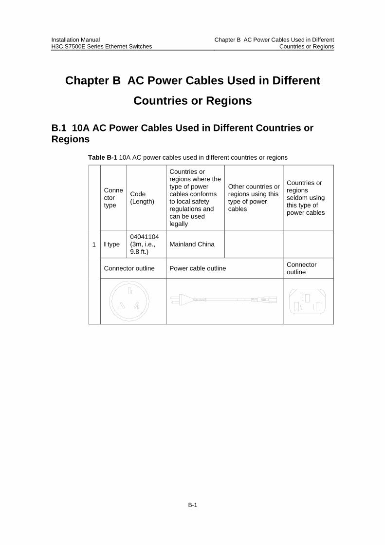
Installation Manual H3C S7500E Series Ethernet Switches
Chapter B AC Power Cables Used in Different Countries or Regions
B-1
Chapter B AC Power Cables Used in Different Countries or Regions
B.1 10A AC Power Cables Used in Different Countries or Regions
Table B-1 10A AC power cables used in different countries or regions
Connector type
Code (Length)
Countries or regions where the type of power cables conforms to local safety regulations and can be used legally
Other countries or regions using this type of power cables
Countries or regions seldom using this type of power cables
I type 04041104 (3m, i.e., 9.8 ft.)
Mainland China
Connector outline Power cable outline Connector outline
1
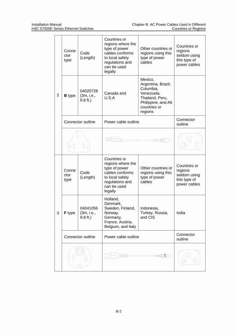
Installation Manual H3C S7500E Series Ethernet Switches
Chapter B AC Power Cables Used in Different Countries or Regions
B-2
Connector type
Code (Length)
Countries or regions where the type of power cables conforms to local safety regulations and can be used legally
Other countries or regions using this type of power cables
Countries or regions seldom using this type of power cables
B type 04020728 (3m, i.e., 9.8 ft.)
Canada and U.S.A
Mexico, Argentina, Brazil, Columbia, Venezuela, Thailand, Peru, Philippine, and A6 countries or regions
Connector outline Power cable outline Connector outline
2
Connector type
Code (Length)
Countries or regions where the type of power cables conforms to local safety regulations and can be used legally
Other countries or regions using this type of power cables
Countries or regions seldom using this type of power cables
F type 04041056 (3m, i.e., 9.8 ft.)
Holland, Denmark, Sweden, Finland, Norway, Germany, France, Austria, Belgium, and Italy
Indonesia, Turkey, Russia, and CIS
India
Connector outline Power cable outline Connector outline
3
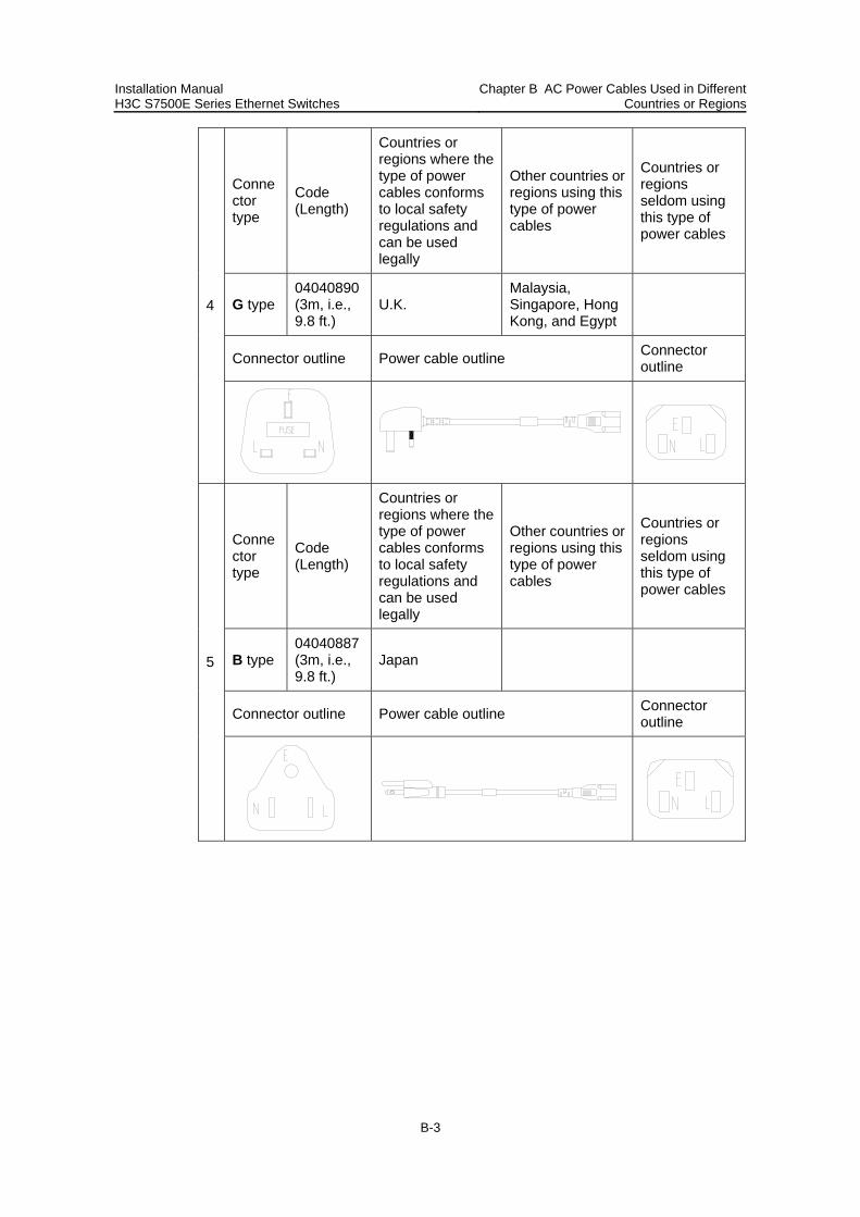
Installation Manual H3C S7500E Series Ethernet Switches
Chapter B AC Power Cables Used in Different Countries or Regions
B-3
Connector type
Code (Length)
Countries or regions where the type of power cables conforms to local safety regulations and can be used legally
Other countries or regions using this type of power cables
Countries or regions seldom using this type of power cables
G type 04040890 (3m, i.e., 9.8 ft.)
U.K. Malaysia, Singapore, Hong Kong, and Egypt
Connector outline Power cable outline Connector outline
4
Connector type
Code (Length)
Countries or regions where the type of power cables conforms to local safety regulations and can be used legally
Other countries or regions using this type of power cables
Countries or regions seldom using this type of power cables
B type 04040887 (3m, i.e., 9.8 ft.)
Japan
Connector outline Power cable outline Connector outline
5
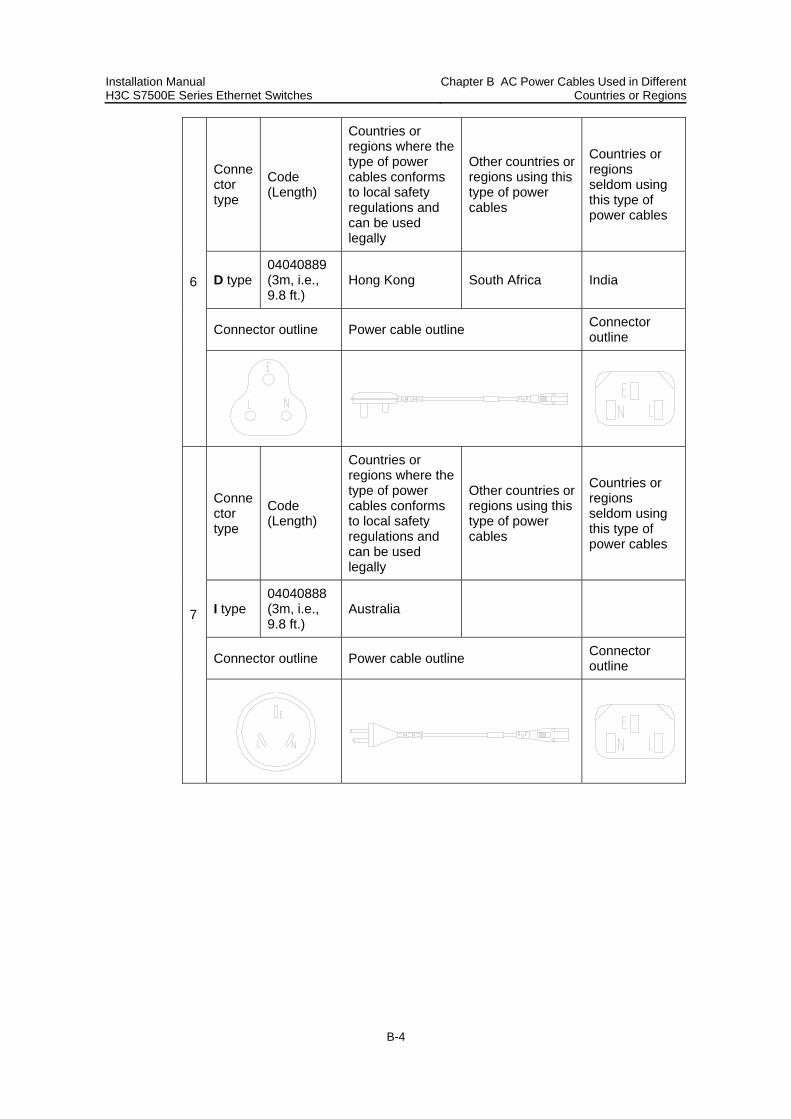
Installation Manual H3C S7500E Series Ethernet Switches
Chapter B AC Power Cables Used in Different Countries or Regions
B-4
Connector type
Code (Length)
Countries or regions where the type of power cables conforms to local safety regulations and can be used legally
Other countries or regions using this type of power cables
Countries or regions seldom using this type of power cables
D type 04040889 (3m, i.e., 9.8 ft.)
Hong Kong South Africa India
Connector outline Power cable outline Connector outline
6
Connector type
Code (Length)
Countries or regions where the type of power cables conforms to local safety regulations and can be used legally
Other countries or regions using this type of power cables
Countries or regions seldom using this type of power cables
I type 04040888 (3m, i.e., 9.8 ft.)
Australia
Connector outline Power cable outline Connector outline
7
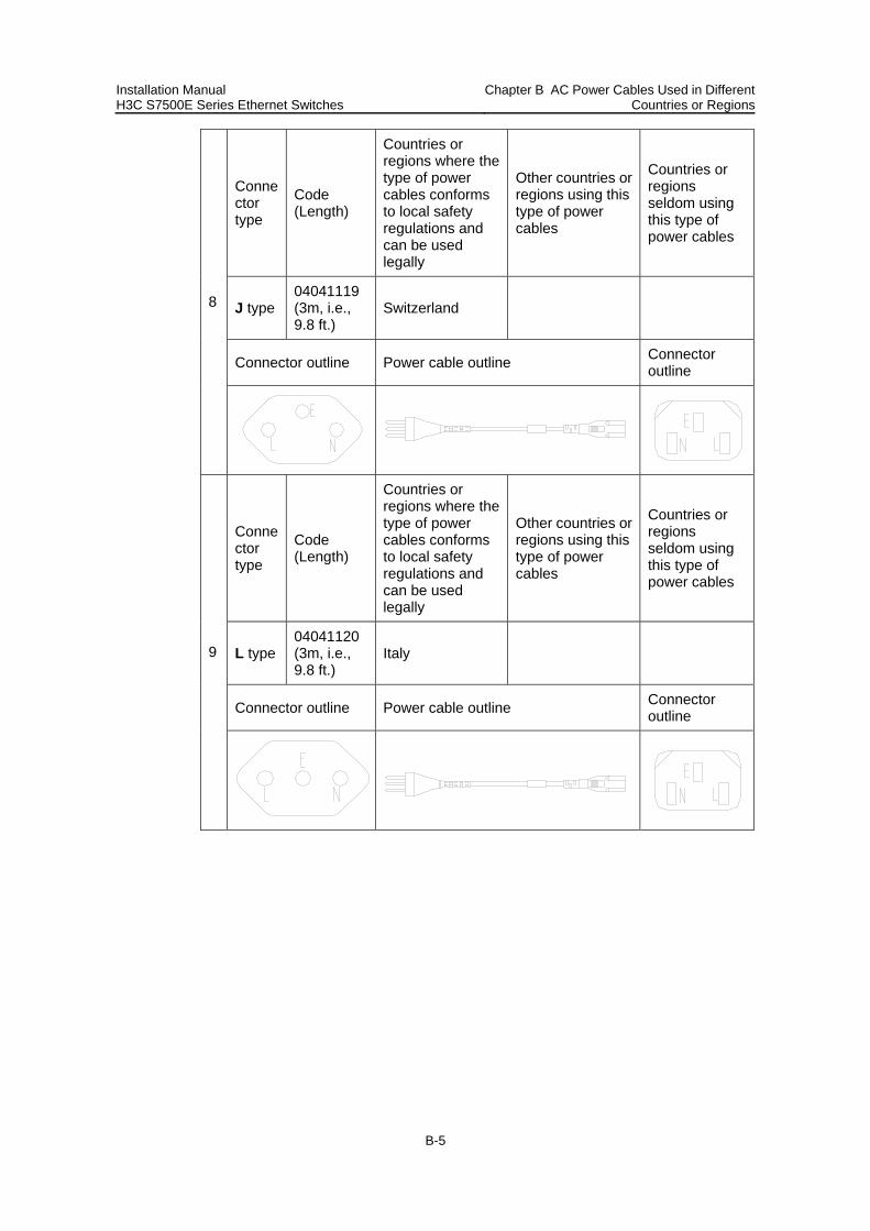
Installation Manual H3C S7500E Series Ethernet Switches
Chapter B AC Power Cables Used in Different Countries or Regions
B-5
Connector type
Code (Length)
Countries or regions where the type of power cables conforms to local safety regulations and can be used legally
Other countries or regions using this type of power cables
Countries or regions seldom using this type of power cables
J type 04041119 (3m, i.e., 9.8 ft.)
Switzerland
Connector outline Power cable outline Connector outline
8
Connector type
Code (Length)
Countries or regions where the type of power cables conforms to local safety regulations and can be used legally
Other countries or regions using this type of power cables
Countries or regions seldom using this type of power cables
L type 04041120 (3m, i.e., 9.8 ft.)
Italy
Connector outline Power cable outline Connector outline
9
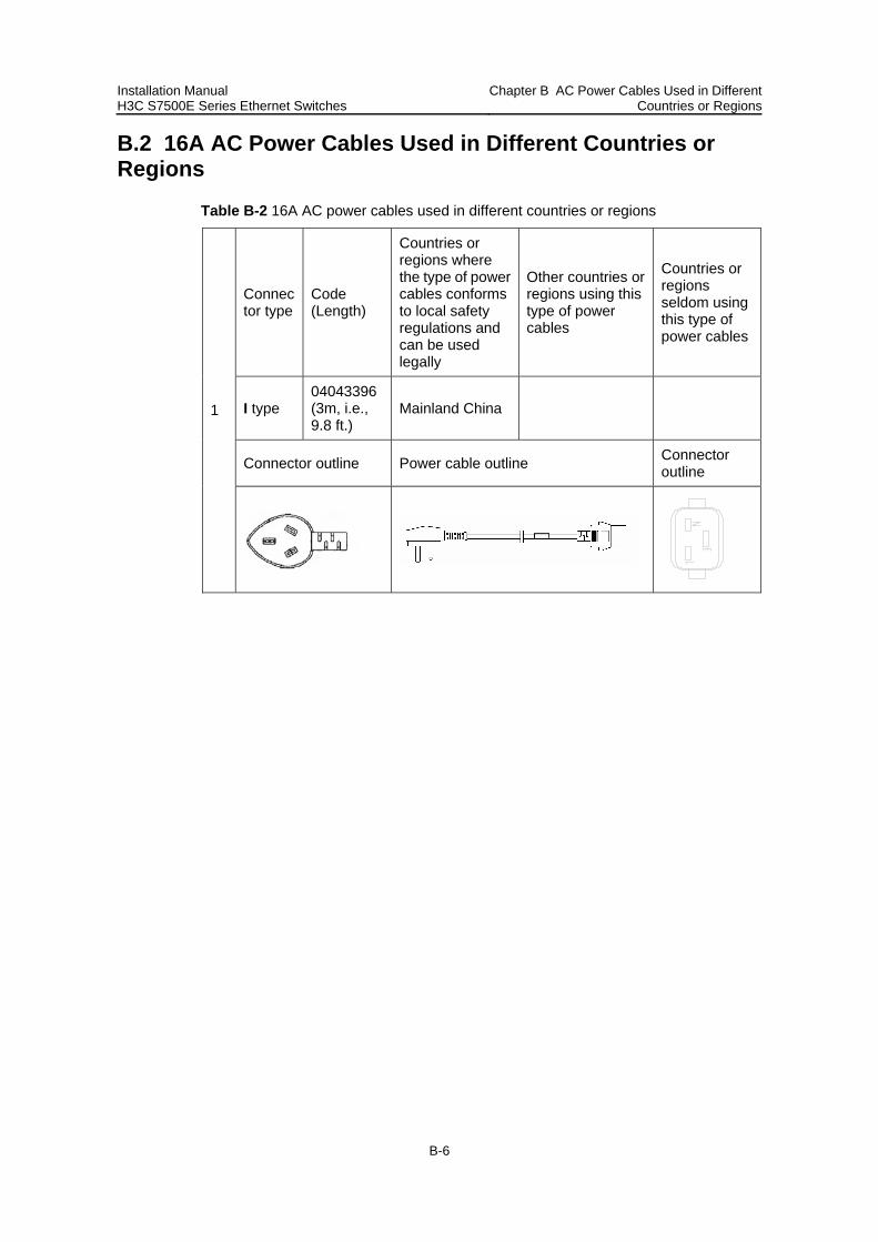
Installation Manual H3C S7500E Series Ethernet Switches
Chapter B AC Power Cables Used in Different Countries or Regions
B-6
B.2 16A AC Power Cables Used in Different Countries or Regions
Table B-2 16A AC power cables used in different countries or regions
Connector type
Code (Length)
Countries or regions where the type of power cables conforms to local safety regulations and can be used legally
Other countries or regions using this type of power cables
Countries or regions seldom using this type of power cables
I type 04043396 (3m, i.e., 9.8 ft.)
Mainland China
Connector outline Power cable outline Connector outline
1
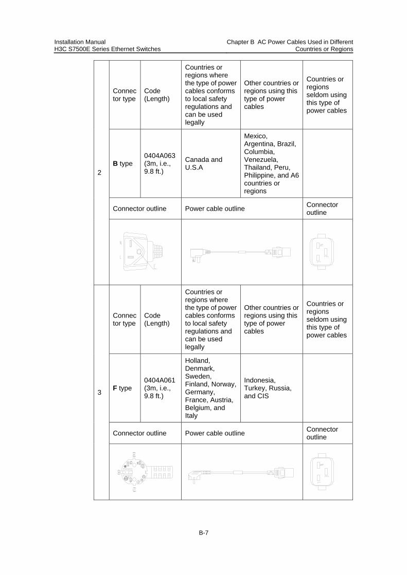
Installation Manual H3C S7500E Series Ethernet Switches
Chapter B AC Power Cables Used in Different Countries or Regions
B-7
Connector type
Code (Length)
Countries or regions where the type of power cables conforms to local safety regulations and can be used legally
Other countries or regions using this type of power cables
Countries or regions seldom using this type of power cables
B type 0404A063 (3m, i.e., 9.8 ft.)
Canada and U.S.A
Mexico, Argentina, Brazil, Columbia, Venezuela, Thailand, Peru, Philippine, and A6 countries or regions
Connector outline Power cable outline Connector outline
2
Connector type
Code (Length)
Countries or regions where the type of power cables conforms to local safety regulations and can be used legally
Other countries or regions using this type of power cables
Countries or regions seldom using this type of power cables
F type 0404A061 (3m, i.e., 9.8 ft.)
Holland, Denmark, Sweden, Finland, Norway, Germany, France, Austria, Belgium, and Italy
Indonesia, Turkey, Russia, and CIS
Connector outline Power cable outline Connector outline
3
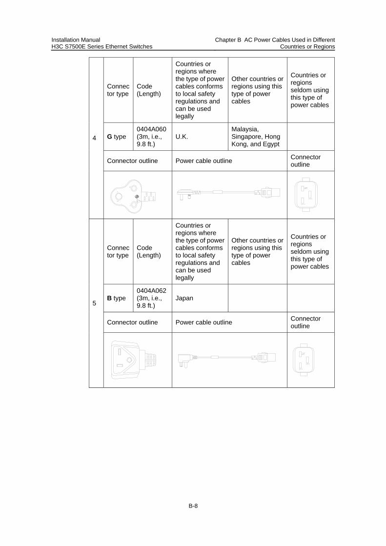
Installation Manual H3C S7500E Series Ethernet Switches
Chapter B AC Power Cables Used in Different Countries or Regions
B-8
Connector type
Code (Length)
Countries or regions where the type of power cables conforms to local safety regulations and can be used legally
Other countries or regions using this type of power cables
Countries or regions seldom using this type of power cables
G type 0404A060 (3m, i.e., 9.8 ft.)
U.K. Malaysia, Singapore, Hong Kong, and Egypt
Connector outline Power cable outline Connector outline
4
Connector type
Code (Length)
Countries or regions where the type of power cables conforms to local safety regulations and can be used legally
Other countries or regions using this type of power cables
Countries or regions seldom using this type of power cables
B type 0404A062 (3m, i.e., 9.8 ft.)
Japan
Connector outline Power cable outline Connector outline
5
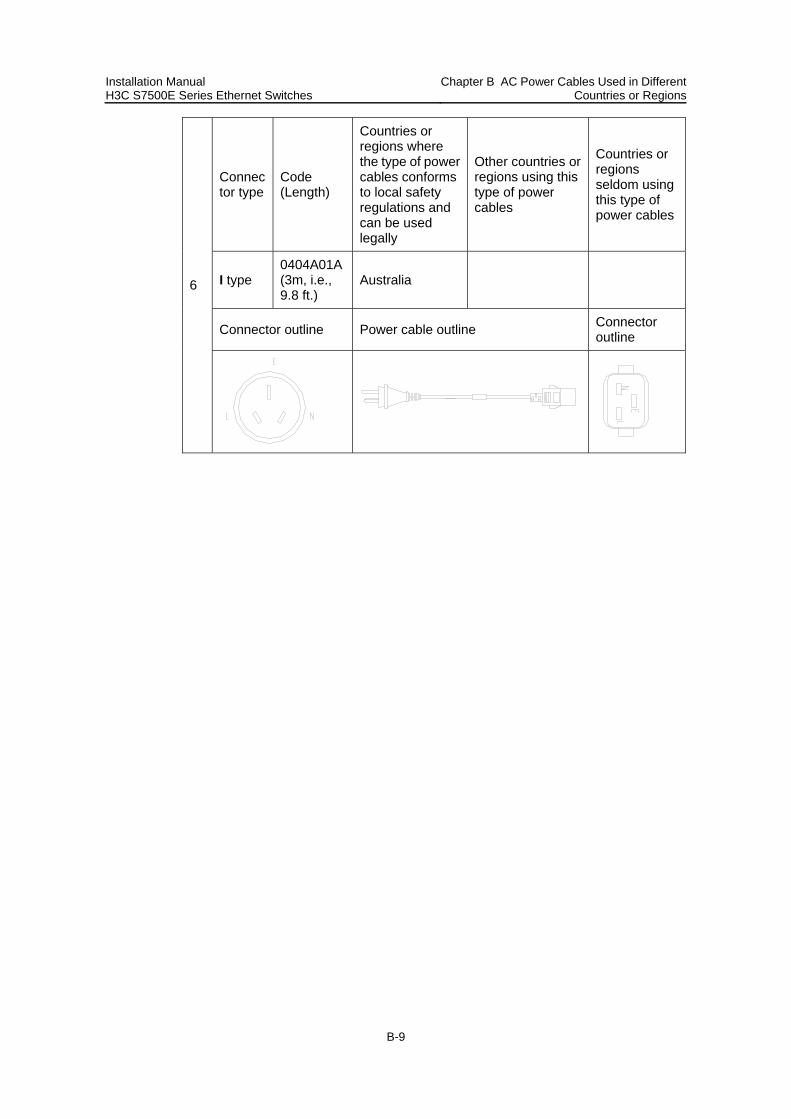
Installation Manual H3C S7500E Series Ethernet Switches
Chapter B AC Power Cables Used in Different Countries or Regions
B-9
Connector type
Code (Length)
Countries or regions where the type of power cables conforms to local safety regulations and can be used legally
Other countries or regions using this type of power cables
Countries or regions seldom using this type of power cables
I type 0404A01A (3m, i.e., 9.8 ft.)
Australia
Connector outline Power cable outline Connector outline
6
Installation Manual H3C S7500E Series Ethernet Switches Table of Contents
i
Table of Contents
Chapter C Compliance and safety manual .................................................................................C-1 C.1 Regulatory compliance statement.....................................................................................C-1
C.1.1 European Community CE Certification DoC ..........................................................C-1 C.2 Regulatory Compliance Information..................................................................................C-2
C.2.1 Regulatory compliance standards ..........................................................................C-2 C.2.2 European Directives compliance............................................................................C-2 C.2.3 USA regulatory compliance ....................................................................................C-2 C.2.4 Canada regulatory compliance...............................................................................C-3 C.2.5 Japan regulatory compliance..................................................................................C-3 C.2.6 CISPR 22 compliance ............................................................................................C-4
C.3 Safety Information Sicherheitsinformationen安全信息......................................................C-4 C.3.1 Overview Überblick 概述 ........................................................................................C-4 C.3.2 Electricity Safety Elektrische Sicherheit 用电安全..................................................C-8 C.3.3 Fuse Sicherung保险丝..........................................................................................C-14 C.3.4 Laser Laser激光辐射 ............................................................................................C-14

Installation Manual H3C S7500E Series Ethernet Switches Chapter C Compliance and safety manual
C-1
Chapter C Compliance and safety manual
C.1 Regulatory compliance statement
C.1.1 European Community CE Certification DoC
Figure C-1 European Community CE Certification DoC

Installation Manual H3C S7500E Series Ethernet Switches Chapter C Compliance and safety manual
C-2
C.2 Regulatory Compliance Information
C.2.1 Regulatory compliance standards
Table C-1 Regulatory compliance standards
Discipline Standards
EMC
FCC Part 15 (CFR 47) CLASS A ICES-003 CLASS A VCCI CLASS A CISPR22 CLASS A EN 55022 CLASS A AS/NZS CISPR22 CLASS A CISPR24 EN 55024 IEC 61000-3-2 IEC 61000-3-3 EN 61000-6-1 ETSI EN 300 386
Safety
UL 60950-1:2003 CAN/CSA C22.2 No 60950-1-03 IEC 60950-1:2001 EN 60950-1/A11:2004 AS/NZS 60950 EN 60825-1 EN 60825-2 FDA 21 CFR Subchapter J
C.2.2 European Directives compliance
H3C S7500E series( including H3C S7502E, H3C S7503E, H3C S7503E-S, H3C S7506E. H3C S7506E-V and H3C S7510E) comply with the following European Directives: 89/336/EC (electromagnetic compatibility), 73/23/EC (low voltage). See Figure1-1 for H3C's Declaration of Conformity
C.2.3 USA regulatory compliance
I. FCC Part 15
H3C S7500E series( including H3C S7502E, H3C S7503E, H3C S7503E-S, H3C S7506E. H3C S7506E-V and H3C S7510E) comply with Part 15 of the FCC Rules. Operation is subject to the following two conditions:
This device may not cause harmful interference.
Installation Manual H3C S7500E Series Ethernet Switches Chapter C Compliance and safety manual
C-3
This device must accept any interference received, including interference that may cause undesired operation.
If the customer modifies the equipment without the authorization of H3C, which directly or indirectly contribute to the equipment incompliance with FCC requirements for Class A digital devices, H3C is not liable for such interference problem and the expenses incurred therefrom shall be covered by the customers.
Note:
This equipment has been tested and found to comply with the limits for a Class A digital device, pursuant to Part 15 of the FCC Rules. These limits are designed to provide reasonable protection against harmful interference when the equipment is operated in a commercial environment. This equipment generates, uses, and can radiate radio frequency energy and, if not installed and used in accordance with the instruction anual, may cause harmful interference to radio communications. Operation of this equipment in a residential area is likely to cause harmful interference in which case the user will be required to correct the interference at his own expense.
II. FDA
H3C S7500E series( including H3C S7502E, H3C S7503E, H3C S7503E-S, H3C S7506E. H3C S7506E-V and H3C S7510E) Conform to the applicable requirements of 21 CFR Subchapter J
C.2.4 Canada regulatory compliance
I. ICES-003
This Class A digital apparatus complies with Canadian ICES-003.
Cet appareil numérique de la classe A est conforme à la norme NMB-003 du Canada.
C.2.5 Japan regulatory compliance
I. VCCI
H3C S7500E series( including H3C S7502E, H3C S7503E, H3C S7503E-S, H3C S7506E. H3C S7506E-V and H3C S7510E) complies with the requirements of VCCI Class A Information Technology Equipment (ITE).
Warning: If this equipment is used in a domestic environment, radio disturbance may arise. When such trouble occurs, the user may be required to take corrective actions.

Installation Manual H3C S7500E Series Ethernet Switches Chapter C Compliance and safety manual
C-4
C.2.6 CISPR 22 compliance
H3C S7500E series (including H3C S7502E, H3C S7503E, H3C S7503E-S, H3C S7506E. H3C S7506E-V and H3C S7510E) complies with the requirements of CISPR 22 for Class A Information Technology Equipment (ITE)
Warning: If this equipment is used in a domestic environment, radio disturbance may arise. When such trouble occurs, the user may be required to take corrective actions.
C.3 Safety Information Sicherheitsinformationen安全信息
C.3.1 Overview Überblick 概述
This section introduces part of the safety precautions that should be followed during the installation and maintenance of the equipment. And for the safety statements and warnings, there followed the translations of both German and Chinese to comply with the national requirements.
Dieser Abschnitt macht Sie mit den Sicherheitsvorschriften vertraut, die Sie bei der Installation und Instandhaltung der Ausrüstung beachten müssen.
本章节介绍了在安装、日常维护本系列设备时,必须遵循的安全预防规范。
Note:
Before any operation is performed, please read the operation instructions and precautions carefully to minimize the possibility of accidents. The Note, Caution, Warning and Danger items in other manuals do not cover all safety precautions that should be followed. They are only the supplements to the safety precautions for operations as a whole. Therefore, the personnel in charge of the installation and maintenance of the products are required to understand these basics of safety operation. In performing various operations, please follow the local safety regulations. The safety precautions introduced in the product manuals are supplementary and subject to the local safety regulations. When various operations are executed on the products, the precautions and special safety instructions provided with the products must be followed to the full. The personnel in charge of the installation and maintenance of the products must be trained as professionals to master the proper operating methods and all safety precautions. Only the trained and qualified personnel can perform operations such as equipment installation and maintenance.

Installation Manual H3C S7500E Series Ethernet Switches Chapter C Compliance and safety manual
C-5
Anmerkung:
Lesen Sie bitte alle Arbeitsanweisungen und Sicherheitvorschriften sorgfältig durch, bevor Sie mit dem Arbeiten beginnen. Nur durch Beachtung dieser Hinweise lässt sich das Unfallrisiko minimieren. Die in anderen Handbüchern aufgeführten Symbole Anmerkung, Achtung, Warnung und Gefahr beinhalten nicht alle zu beachtenden Sicherheitvorschriften. Sie dienen lediglich der Ergänzung. Deshalb muss sich das für die Installation und Instandhaltung der Ausrüstung verantwortliche Personal mit allen Sicherheitshinweise vertraut machen. Bei der Durchführung der verschiedenen Arbeitsschritte müssen außerdem die örtlichen Sicherheitsvorschriften beachtet werden. Die in den Handbüchern der einzelnen Produkte aufgeführten Sicherheitshinweise sind Ergänzungen und unterliegen den nationalen Sicherheitsvorschriften. Während der Arbeit mit den Produkten sind deshalb grundsätzlich alle Sicherheitsvorschriften und spezifischen Sicherheitshinweise genau zu beachten. Das für die Installation und Instandhaltung der Produkte verantwortliche Pesonal muss geschult werden, um alle Sicherheitsvorschriften zu kennen und die richtigen Arbeitsmethoden anwenden zu können. Nur geschultes und qualifiziertes Personal kann die Installation und Instandhaltung in korrekter Weise durchführen.
说明:
为了避免可能发生的事故,请在进行任何操作前,仔细阅读设备操作手册和本章节的安
全规范。手册中 出现的说明、注意、警告、危险,不能涵盖所有的安全预防,仅仅是在
整个操作过程中的安全提示和补充。因此,负责安装和日常维护本设备的人员必须具备
安全操作基本技能。 操作人员要按照当地的安全规范进行操作。出现在产品手册中的安全预防措施仅仅是当
地安全规范的补充。 在操作本设备时,请认真执行产品手册规定的安全规范。 设备安装、维护人员必须通过专业培训,并且掌握足够的操作技能和安规预防意识。只
有专业人员才能担任本设备的安装和维护工作。
I. Conventions Used Symbole Erläuterung 应用惯例
The symbols in this manual are shown in the following table. They are used to remind the reader of the safety precautions during equipment installation and maintenance.
Die Symbole in diesem Handbuch verwendeten sind in der folgenden Tabelle dargestellt. Diese Symbole sollen das Personal während der Installation und Instandhaltung der Ausrüstung an die Wichtigkeit der im Handbuch aufgeführten Sicherheitsvorschriften erinnern.
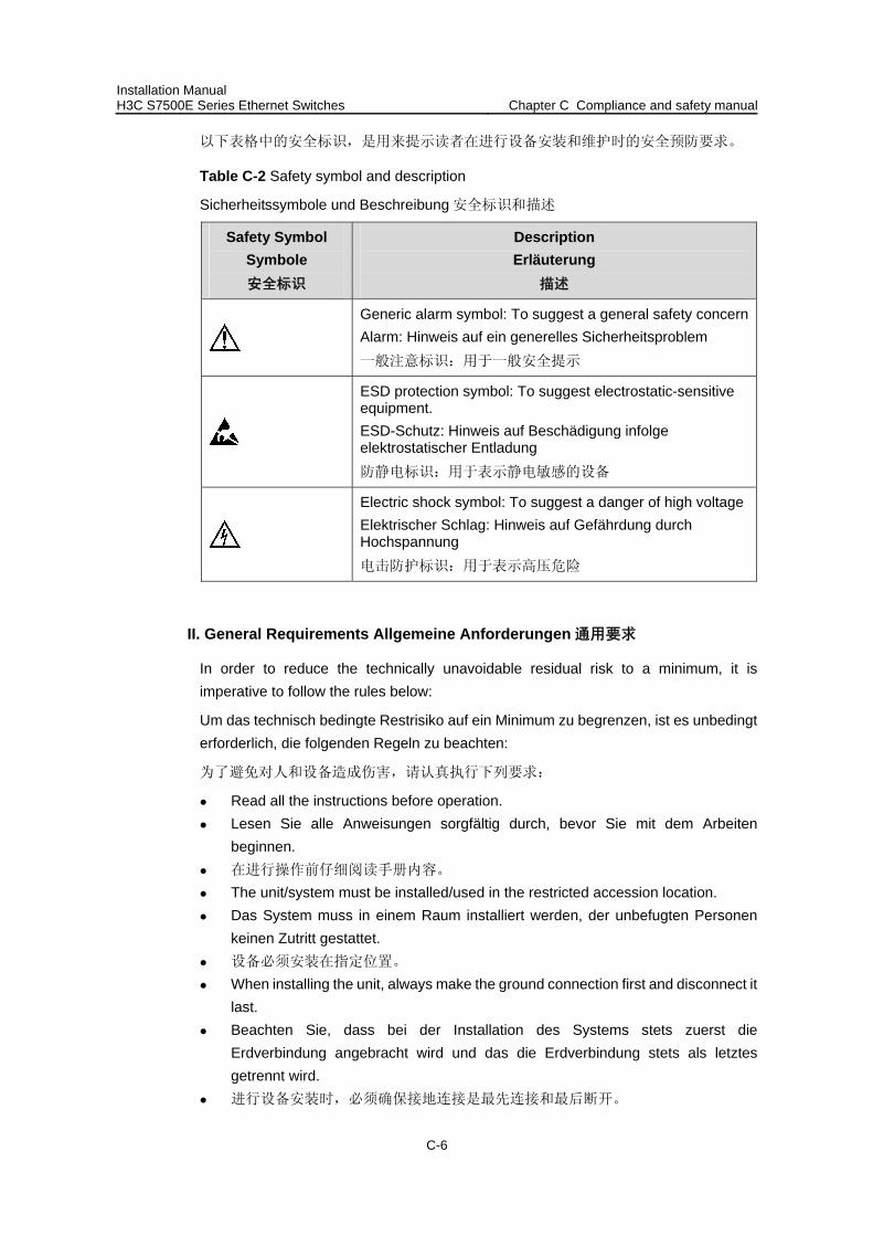
Installation Manual H3C S7500E Series Ethernet Switches Chapter C Compliance and safety manual
C-6
以下表格中的安全标识,是用来提示读者在进行设备安装和维护时的安全预防要求。
Table C-2 Safety symbol and description
Sicherheitssymbole und Beschreibung 安全标识和描述
Safety Symbol Symbole 安全标识
Description Erläuterung
描述
Generic alarm symbol: To suggest a general safety concernAlarm: Hinweis auf ein generelles Sicherheitsproblem 一般注意标识:用于一般安全提示
ESD protection symbol: To suggest electrostatic-sensitive equipment. ESD-Schutz: Hinweis auf Beschädigung infolge elektrostatischer Entladung 防静电标识:用于表示静电敏感的设备
Electric shock symbol: To suggest a danger of high voltage Elektrischer Schlag: Hinweis auf Gefährdung durch Hochspannung 电击防护标识:用于表示高压危险
II. General Requirements Allgemeine Anforderungen 通用要求
In order to reduce the technically unavoidable residual risk to a minimum, it is imperative to follow the rules below:
Um das technisch bedingte Restrisiko auf ein Minimum zu begrenzen, ist es unbedingt erforderlich, die folgenden Regeln zu beachten:
为了避免对人和设备造成伤害,请认真执行下列要求:
Read all the instructions before operation. Lesen Sie alle Anweisungen sorgfältig durch, bevor Sie mit dem Arbeiten
beginnen. 在进行操作前仔细阅读手册内容。 The unit/system must be installed/used in the restricted accession location. Das System muss in einem Raum installiert werden, der unbefugten Personen
keinen Zutritt gestattet. 设备必须安装在指定位置。 When installing the unit, always make the ground connection first and disconnect it
last. Beachten Sie, dass bei der Installation des Systems stets zuerst die
Erdverbindung angebracht wird und das die Erdverbindung stets als letztes getrennt wird.
进行设备安装时,必须确保接地连接是最先连接和最后断开。

Installation Manual H3C S7500E Series Ethernet Switches Chapter C Compliance and safety manual
C-7
Do not block ventilation openings while the system is on, and keep at least 5 cm distance from ventilation openings and walls or other things which may block the openings
Sorgen Sie dafür, dass die Öffnungen der Ventilation zu keinem Zeitpunkt verschlossen, verstopft oder anderweitig blockiert sind. Zwischen den Ventilationsöffnungen und Wänden bzw. anderen Gegenständen muss stets ein Abstand von mindestens 5cm bestehen.
设备在工作时必须确保通风口的畅通,确保设备离墙壁或是其它的可能堵塞通风口
的物体的间距至少 5cm。 Never defeat the ground conductor or operate the equipment in the absence of a
suitably installed ground conductor. Contact the appropriate electrical inspection. Betreiben Sie die Ausrüstung niemals ohne Erdung. Trennen Sie das System
nicht von der Erdung. 不允许破坏设备的接地导线或是在无接地连接的情况下操作设备,要进行适当的电
气检查。 The unit/system must be connected to the protection ground before operation
permanently. And the cross-section of protective earthing conductor shall be at least 1.5mm2
Das System muss vor der ständigen Inbetriebnahme geerdet werden. Der Querschnitt der Erdverbindung sollte mindestens 1.5mm² betragen.
进行设备/系统操作前,请确保永久接地,并且用于进行保护接地连接的接地线截面
不小于 1.5mm2。 For AC supplied model: The device applies to TN power systems. Mit Wechselstrom betriebenes Modell: Das Gerät arbeitet mit einem
Phase-Nullleiter-System. AC 电源输入:此设备用于 TN 电源系统。 For DC supplied model: The device applies to DC power source that complies with
the Safety Extra-Low Voltage (SELV) requirements in IEC 60950 based safety standards.
Mit Gleichstrom betriebenes Modell: Das Gerät arbeitet mit Gleichstrom, wobei die Anforderungen der Norm (IEC60950) für Schutzkleinspannung eingehalten werden müssen.
DC 电源输入:设备使用满足 IEC60950 安规标准的安全超低电压(SELV)电源。 This product relies on the building’s installation for short-circuit (overcurrent)
protection. It is required to use a fuse or circuit breaker no larger than 120 VAC, 20A U.S. (240 VAC, 16A international) or 80VDC, 238A. on the phase conductors (all current-carrying conductors).
Dieses Produkt muss so installiert werden, dass es gegen Kurzschluss (Überstrom) abgesichert ist. Stellen Sie sicher, dass die Sicherungswerte auf allen Phasen nicht größer als 120VAC, 20A U.S. (240VAC, 16A international) bei den mit Wechselstrom betriebenen Modellen sowie 80VDC, 238A. bei den mit Gleichstrom betriebenen Modellen sind.

Installation Manual H3C S7500E Series Ethernet Switches Chapter C Compliance and safety manual
C-8
该产品需要使用建筑物安装来提供短路保护,要求保险丝或者短路保护器不小于
120 VAC, 15A U.S. (240 VAC, 10A international),或者 80Vdc, 238A. For AC supplied model: The plug-socket combination must be accessible at all
times because it serves as the main disconnecting device. Mit Wechselstrom betriebenes Modell: Der Netzstecker muss jederzeit leicht
zugänglich sein. AC 供电:插座必须随时可用,因为它是主要的切断电源装置。 To prevent laser radiation from hurting your eyes, never stare into the open optical
port. Nehmen Sie das Gerät nicht in Betrieb, solange das optische Fenster nicht
geschlossen ist. Der Laserstrahl kann zu Augenverletzungen führen. 为了避免光纤发出的高能量的激光光束伤害到视网膜,请不要直视光接口。 The resistence of PD for PoE port in all the tests is 240ohm 20W. Der Widerstand von PD gegen PoE-Port in allen Testen is 240 Ohm 20W. 测试使用的 PoE 负载是 240 欧姆,20 瓦. The product can not be used as floor-standing equipment. Das Produkt kann nicht als auf dem Boden stehende Anlage gebraucht werden. 此设备不能作为落地设备使用. The equipment is to be connected only to POE networks without routing to the
outside plant. Die Anlage ist lediglich mit POE-Netzwerk ohne Route zur Außenvorrichtung zu
verbinden. 设备的 PoE 口网线不能出户. The DC mains supply must be earthed. Die DC-Hauptversorgung muß geerdet werden. 设备的 DC 供电系统必须接地. For DC supplied model: The circuit breaker must be accessible at all times
because it serves as the main disconnecting device. Für das angebotene DC-Modell: der Stromkreisbrecher muß jederzeit erreichbar
sein, denn er dient als Hauptabtrennungsgerät. DC 供电,空开必须随时可用, 因为它是主要的切断电源装置.
C.3.2 Electricity Safety Elektrische Sicherheit 用电安全
I. High Voltage Hochspannung 高电压
Danger:
High voltage power supply offers electric power for equipment operation. Direct contact or indirect contact (via damp objects) with high voltage and AC mains supply may result in fatal danger.
Installation Manual H3C S7500E Series Ethernet Switches Chapter C Compliance and safety manual
C-9
Gefahr:
Die Hochspannungsleitungen stellen für die Arbeit der Ausrüstung erforderliche Energie zur Verfügung. Direkter oder indirekter Kontakt (z. B. durch feuchte Gegenstände) mit Hochspannung und Wechselstromversorgung kann zu tödlichen Unfällen führen.
危险:
高压电源为设备运行提供电能,直接或是间接(通过潮湿的物体)接触高压和 AC 交流
电源输入,都会导致致命危险。
During the installation of AC power supply facility, the local safety regulations must be followed. The personnel who install the AC facility must be qualified for high voltage and AC operations.
Bei der Installation der Wechselstromversorgung sind die örtlichen Sicherheitsbestimmungen zu beachten. Das Personal muss besonders qualifiziert sein für das Arbeiten mit Hochspannung und Wechselstrom.
必须按照当地安全规定进行 AC 交流供电设备的安装。负责电源安装的人员必须是
通过高压和电源操作专业培训的专业人员。 Conducting articles, such as watch, hand chain, bracelet and ring are prohibited
during the operation. Es ist nicht erlaubt während dieser Arbeiten leitende Gegenstände wie Uhren,
Armbänder, Armreifen und Ringe am Körper zu tragen. 在操作中不能穿戴导电性的物品,如:手表,手琏,手镯和项链等。 When water is found in the rack, or the rack is damp, please immediately switch off
the power supply. Sollte sich Wasser im Baugruppenträger befinden oder der Baugruppenträger
feucht sein, ist die Energiezufuhr sofort zu unterbrechen und das System abzuschalten.
当有液体进入机架或机架有损坏时,请立即切断电源。 When operation is performed in a damp environment, make sure that water is kept
off the equipment. Muss in einem feuchten Umgebung gearbeitet werden, ist sicherzustellen, dass
kein Wasser in die Ausrüstung dringen kann. 在潮湿环境下进行安装时,请避免液体进入设备。
Installation Manual H3C S7500E Series Ethernet Switches Chapter C Compliance and safety manual
C-10
Warning:
Non-standard and improper high voltage operations may result in fire and electric shock. Therefore, AC cable bridging and wiring through a certain area must follow the local rules and regulations. The personnel who perform high voltage operations should be qualified for high voltage and AC operations.
Warnung:
Die Nichtbeachtung der Sicherheitsvorschriften bei der Arbeit mit Hochspannung kann zu Feuer und elektrischem Schlag führen. Deshalb muss die Verlegung von Leitungen und Verbindungen den örtlichen Anforderungen und Sicherheitsvorschriften entsprechen. Arbeiten mit Hochspannung dürfen nur von qualifiziertem Fachpersonal durchgeführt werden.
警告:
不规范和不正确的高压电源操作,都会导致失火和电击危险。因此,必须由通过高压和
AC 电源操作专业培训的专业人员按照当地电气安全规定配置线缆。
II. Power Cable Zuleitung 电缆
Note:
Installation and removal of live power cable is prohibited strictly. Transient contact between the core of power cable and conductor may generate electric arc or spark or electric arc, which may lead to fire or eye injury.
Anmerkung:
Das Entfernen und Anbringen von Zuleitungen ist strengstens verboten. Kurzschlüsse zwischen innerem und äußerem Leiter können Lichtbögen oder Funkenflug verursachen, was zu Feuer oder einer Augenverletzung führen kann.
Installation Manual H3C S7500E Series Ethernet Switches Chapter C Compliance and safety manual
C-11
说明:
禁止安装和移动带电的线缆。因为导电体和带电的线缆,即使短暂接触,也会引起电火
花或电弧,从而导致失火或是伤害眼睛。
Before the power cable is installed or removed, the power switch must be turned off.
Das System muss stets abgeschaltet werden, bevor die Zuleitung angebracht oder entfernt wird.
在安装、移动线缆之前,请切断电源。 Before the power cable is connected, it must be confirmed that the power cable
and label comply with the requirements of the actual installation. Überprüfen Sie vor dem Anbringen der Zuleitung immer, ob das von Ihnen
verwendete Kabel den Anforderungen entspricht. 在进行线缆连接前,请确认线缆和线缆的标识与实际安装要求是一致的。
Installation Manual H3C S7500E Series Ethernet Switches Chapter C Compliance and safety manual
C-12
Note:
For H3C S7502E, H3C S7503E-S,: For DC power supplied equipment, please use 4 mm2 or 10 AWG minimum power supply cord. For POE input: please use 10 mm2 or 6 AWG minimum power supply cord For AC power supplied equipment, please use 1.25 mm2 or 16 AWG minimum power supply cord. For H3C S7503E, H3C S7506E, H3C S7506E-V and H3C S7510E: For DC power supplied equipment, With POE input: please use 50 mm2 or 0 AWG minimum power supply cord. Without POE input: please use 10 mm2 or 6 AWG minimum power supply cord. For AC power supplied equipment, please use 2.5 mm2 or 12 AWG minimum power supply cord.
Anmerkung:
Für H3C S7502E, H3C S7503E-S,: Für Gleichstrom-Versorgung Ausrüstung, benutzen Sie bitte 4 mm2 oder 10 AWG-Lehre minimale Spg.Versorgungsteilschnur. Für POE Eingang, benutzen Sie bitte 10 mm2 oder 6 AWG-Lehre minimale Spg.Versorgungsteilschnur. Für Wechselstrom-Versorgung Ausrüstung, benutzen Sie bitte 1.25 mm2 oder 16 AWG-Lehre minimale Spg.Versorgungsteilschnur. Für H3C S7503E, H3C S7506E, H3C S7506E-V und H3C S7510E: Für Gleichstrom-Versorgung Ausrüstung Mit POE Eingang: benutzen Sie bitte 50 mm2 oder 0 AWG-Lehre minimale Spg.Versorgungsteilschnur. Ohne POE Eingang: benutzen Sie bitte 10 mm2 oder 6 AWG-Lehre minimale Spg.Versorgungsteilschnur. Für Wechselstrom-Versorgung Ausrüstung, benutzen Sie bitte 2.5 mm2 oder 12 AWG-Lehre minimale Spg.Versorgungsteilschnur.

Installation Manual H3C S7500E Series Ethernet Switches Chapter C Compliance and safety manual
C-13
说明:
对于 H3C S7502E, H3C S7503E-S,: DC 电源设备,请使用 4 mm2 或 10 AWG 电缆; POE 输入, 请使用 10 mm2 或 6AWG 电缆; AC 电源设备,请使用 1.25mm2 或 16AWG 电缆; 对于 H3C S7503E, H3C S7506E, H3C S7506E-V 和 H3C S7510E: DC 电源设备, 有 POE 功能, 请使用 50 mm2 或 0 AWG 电缆; 无 POE 功能, 请使用 10 mm2 或 6 AWG 电缆; AC 电源设备,请使用 2.5mm2 或 12AWG 电缆;
III. Thunderstorm Gewitter 防雷击
Danger:
High voltage and AC operations or operations on a steel tower and a mast on a thunderstorm day are prohibited.
Gefahr:
Arbeiten mit Hochspannung und Wechselstrom oder Arbeiten auf Stahltürmen und masten während eines Gewitters sind verboten.
危险:
禁止在雷雨天进行高压电源和 AC 交流电源安装操作,对金属架和天线的操作也是不允
许的。
In order to prevent the equipment from being damaged by lightning, proper grounding is required.
Installation Manual H3C S7500E Series Ethernet Switches Chapter C Compliance and safety manual
C-14
C.3.3 Fuse Sicherung 保险丝
Warning:
For the safety of continuous operation, please replace the fuse with that of the same type and rating, if necessary.
Warnung:
Ersetzen Sie die Sicherung bei Bedarf immer nur mit einem Sicherungstyp, der die gleichen technischen Daten besitzt.
警告:
为了产品持续操作的安全,必须更换相同型号和相同规格的保险丝。
C.3.4 Laser Laser 激光辐射
The laser hazard level of this equipment is Class 1.
Die von diesem Laser ausgehende Gefahr entspricht der Kategorie 1.
本设备的激光防护等级是 1 类
Warning:
When performing installation and maintenance operations of optical fibers, you should not stand close to, or look into the optical fiber outlet directly with unaided eyes.
Warnung:
Während der Installation und Instandhaltung der optischen Fasern dürfen Sie nicht zu nahe am Ausgang der optischen Fasern stehen und nicht ohne Augenschutz in die optischen Fasern sehen.

Installation Manual H3C S7500E Series Ethernet Switches Chapter C Compliance and safety manual
C-15
警告:
在安装和维护设备的光纤接口时,请不要把眼睛靠近或是直视这些光接口。