h. pre-engineered and prescriptive foundation designs · h. pre-engineered and prescriptive...
TRANSCRIPT
PROTECTING MaNufaCTuREd HOMEs fROM flOOds aNd OTHER HazaRds A Multi -Hazard Foundation and Installation Guide
H-�
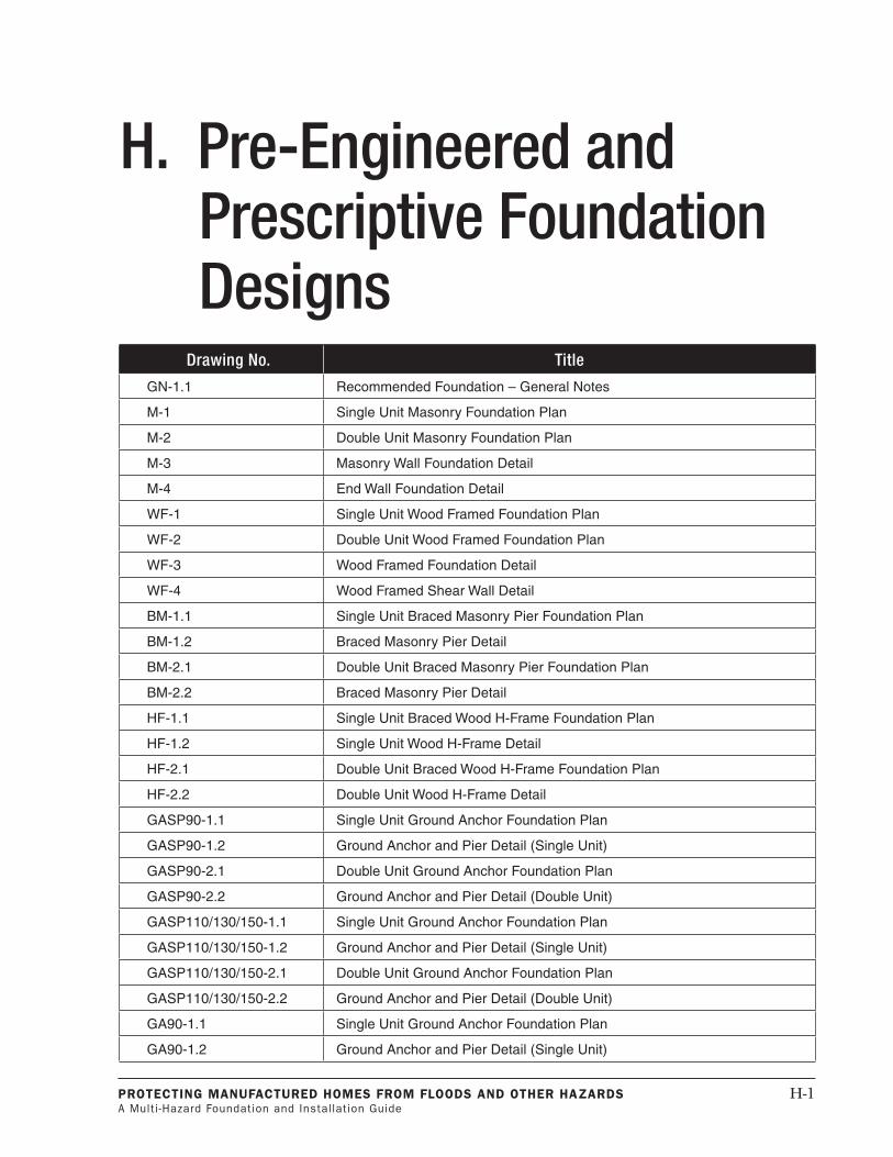
H. Pre-EngineeredandPrescriptiveFoundationDesigns
DrawingNo. Title
GN-1.1 Recommended Foundation – General Notes
M-1 Single Unit Masonry Foundation Plan
M-2 Double Unit Masonry Foundation Plan
M-3 Masonry Wall Foundation Detail
M-4 End Wall Foundation Detail
WF-1 Single Unit Wood Framed Foundation Plan
WF-2 Double Unit Wood Framed Foundation Plan
WF-3 Wood Framed Foundation Detail
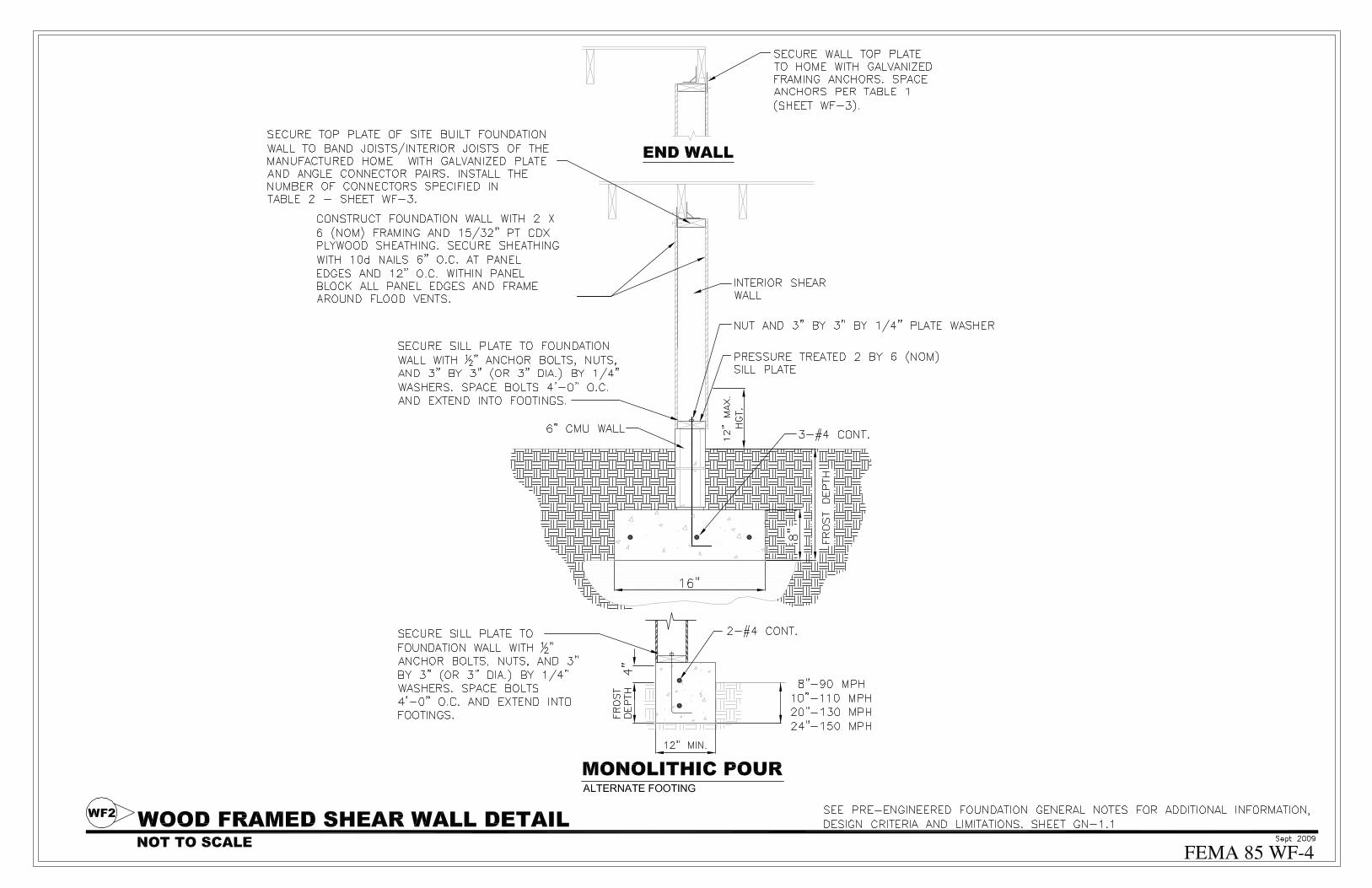
WF-4 Wood Framed Shear Wall Detail
BM-1.1 Single Unit Braced Masonry Pier Foundation Plan
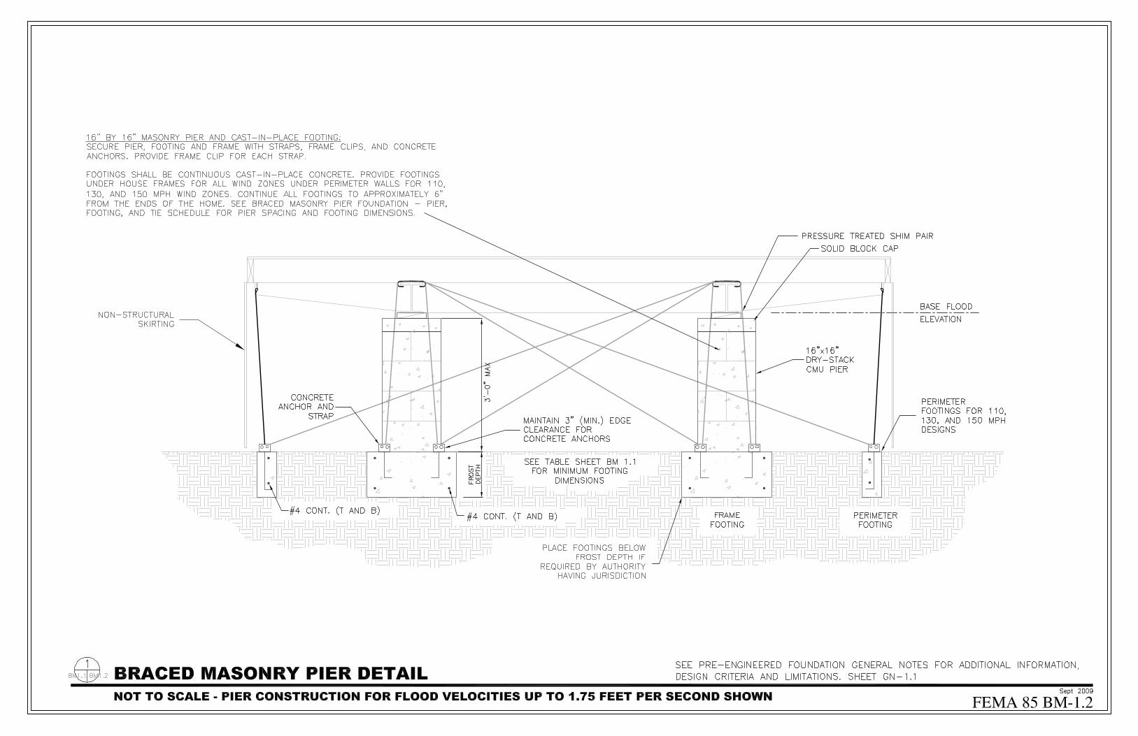
BM-1.2 Braced Masonry Pier Detail
BM-2.1 Double Unit Braced Masonry Pier Foundation Plan
BM-2.2 Braced Masonry Pier Detail
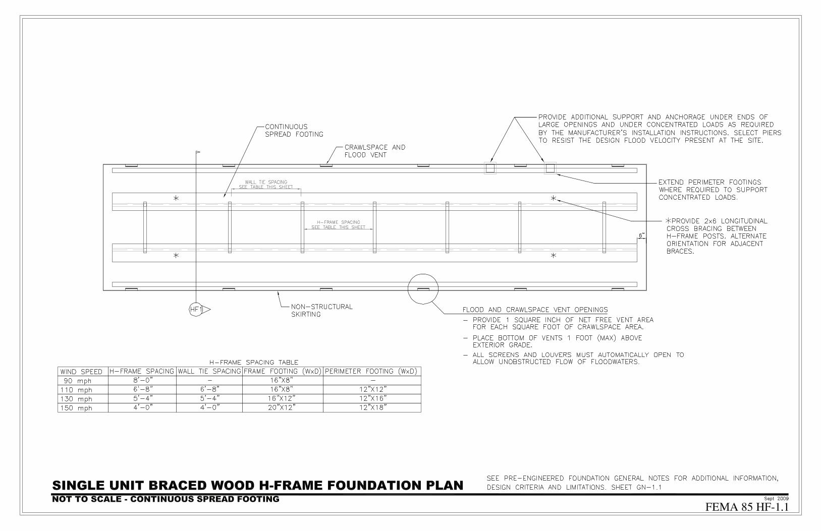
HF-1.1 Single Unit Braced Wood H-Frame Foundation Plan
HF-1.2 Single Unit Wood H-Frame Detail
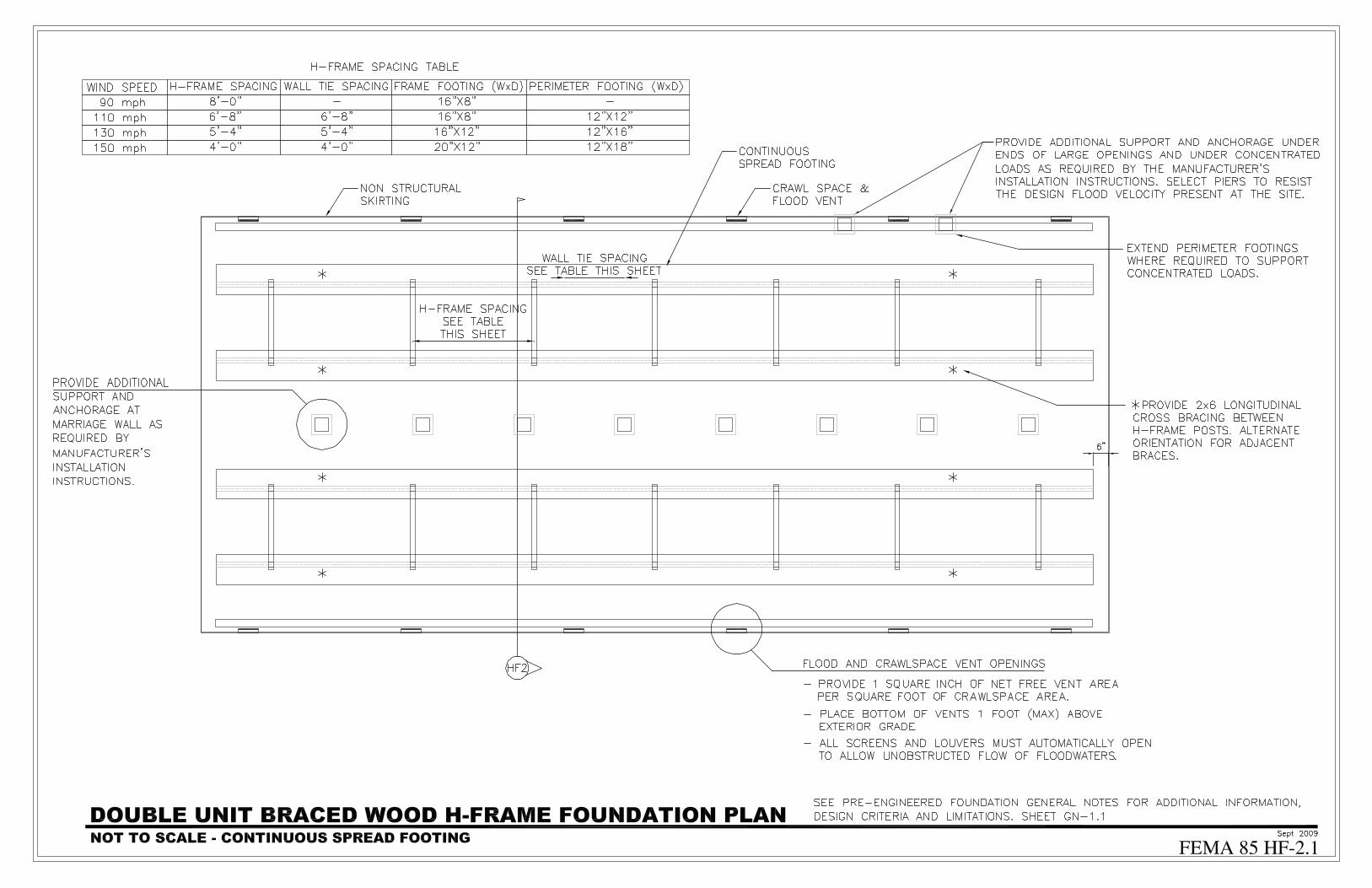
HF-2.1 Double Unit Braced Wood H-Frame Foundation Plan
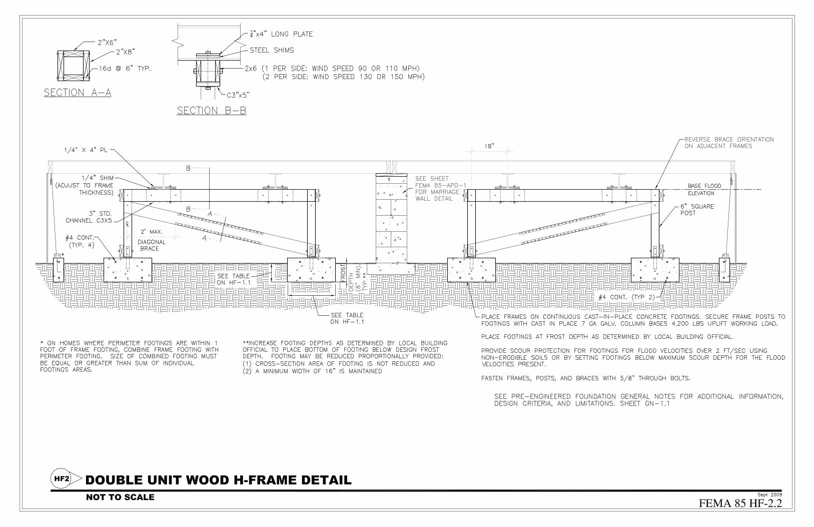
HF-2.2 Double Unit Wood H-Frame Detail
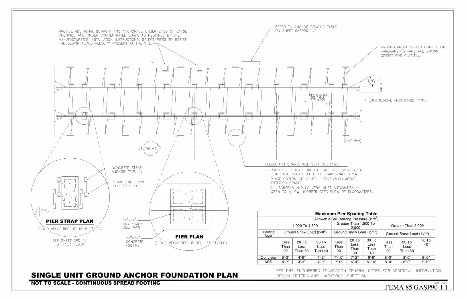
GASP90-1.1 Single Unit Ground Anchor Foundation Plan
GASP90-1.2 Ground Anchor and Pier Detail (Single Unit)
GASP90-2.1 Double Unit Ground Anchor Foundation Plan
GASP90-2.2 Ground Anchor and Pier Detail (Double Unit)
GASP110/130/150-1.1 Single Unit Ground Anchor Foundation Plan
GASP110/130/150-1.2 Ground Anchor and Pier Detail (Single Unit)
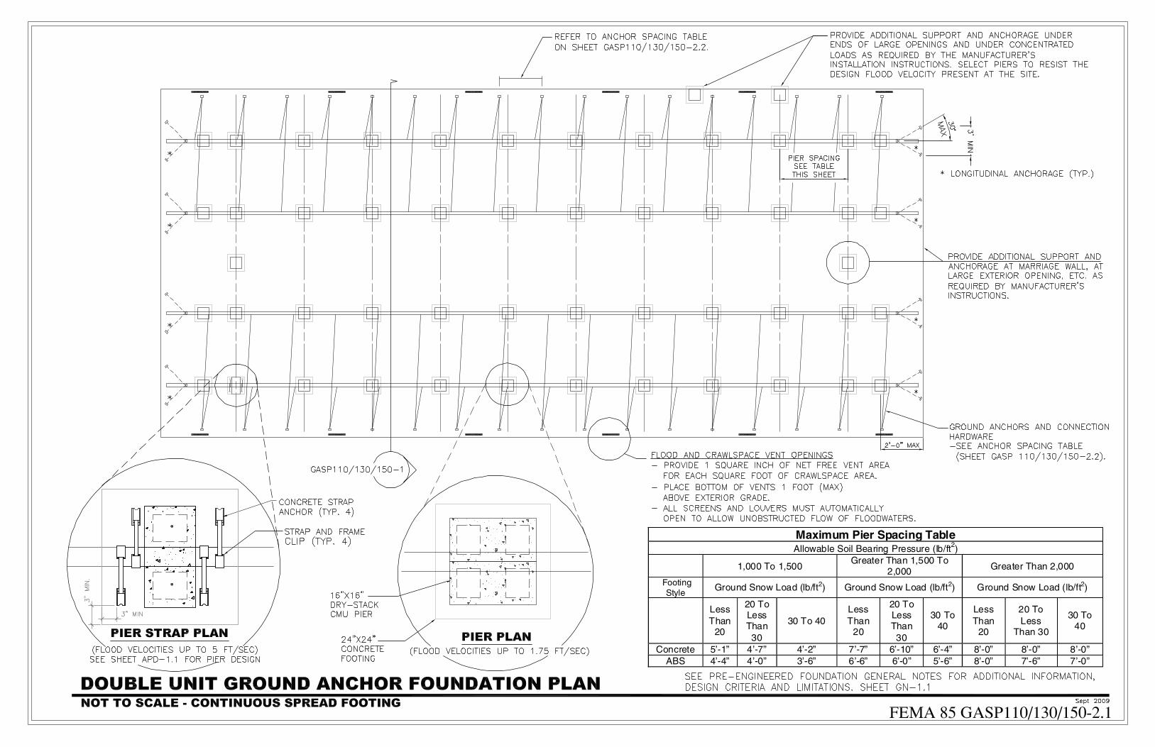
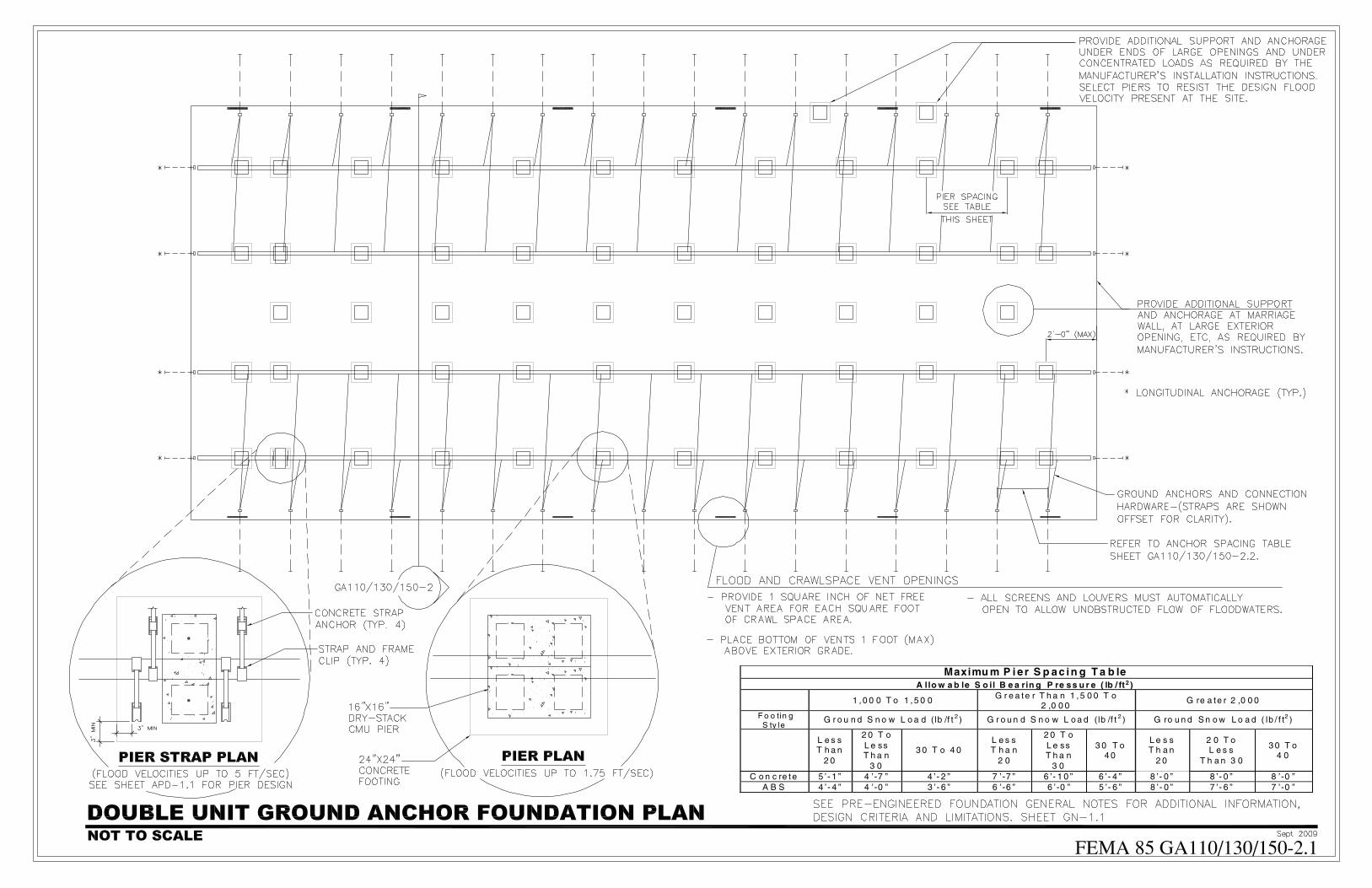
GASP110/130/150-2.1 Double Unit Ground Anchor Foundation Plan
GASP110/130/150-2.2 Ground Anchor and Pier Detail (Double Unit)
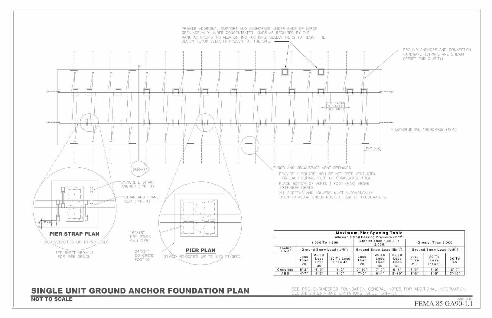
GA90-1.1 Single Unit Ground Anchor Foundation Plan
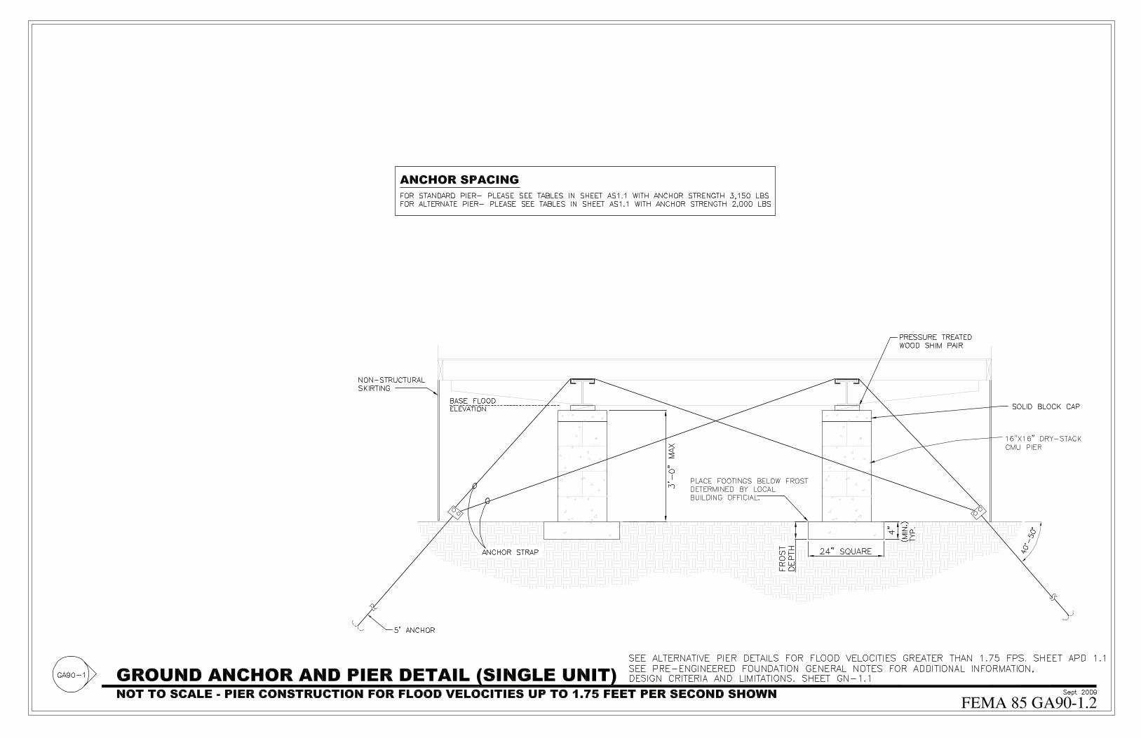
GA90-1.2 Ground Anchor and Pier Detail (Single Unit)
H-� PROTECTING MaNufaCTuREd HOMEs fROM flOOds aNd OTHER HazaRds A Multi -Hazard Foundation and Installation Guide
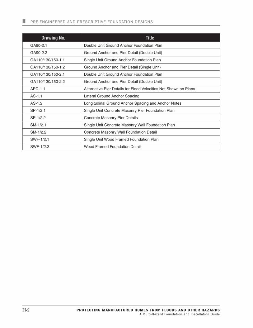
H Pre-enGIneered And PrescrIPtIve FoundAtIon desIGns
DrawingNo. Title
GA90-2.1 Double Unit Ground Anchor Foundation Plan
GA90-2.2 Ground Anchor and Pier Detail (Double Unit)
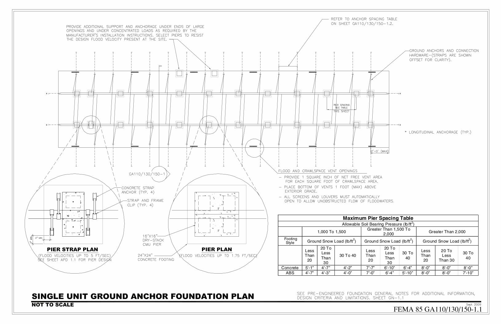
GA110/130/150-1.1 Single Unit Ground Anchor Foundation Plan
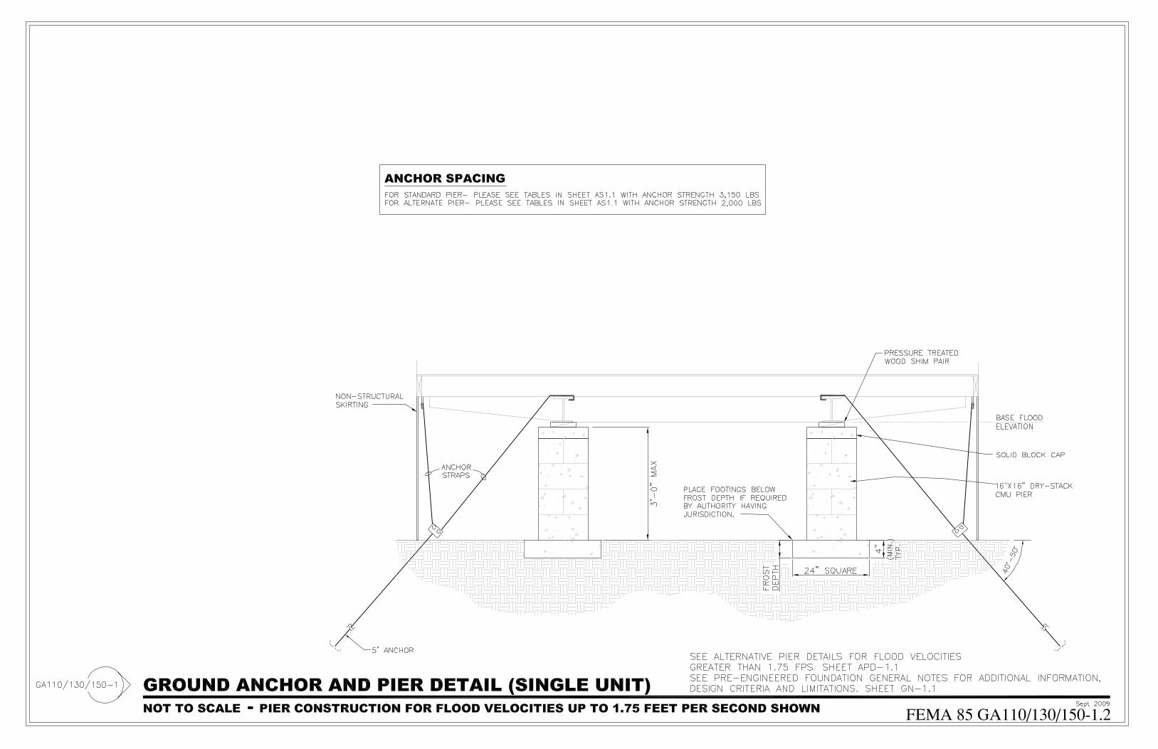
GA110/130/150-1.2 Ground Anchor and Pier Detail (Single Unit)
GA110/130/150-2.1 Double Unit Ground Anchor Foundation Plan
GA110/130/150-2.2 Ground Anchor and Pier Detail (Double Unit)
APD-1.1 Alternative Pier Details for Flood Velocities Not Shown on Plans
AS-1.1 Lateral Ground Anchor Spacing
AS-1.2 Longitudinal Ground Anchor Spacing and Anchor Notes
SP-1/2.1 Single Unit Concrete Masonry Pier Foundation Plan
SP-1/2.2 Concrete Masonry Pier Details
SM-1/2.1 Single Unit Concrete Masonry Wall Foundation Plan
SM-1/2.2 Concrete Masonry Wall Foundation Detail
SWF-1/2.1 Single Unit Wood Framed Foundation Plan
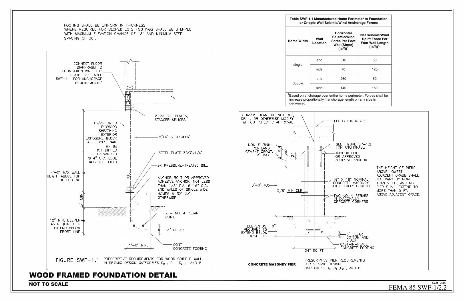
SWF-1/2.2 Wood Framed Foundation Detail
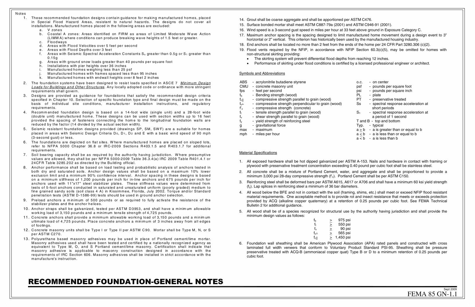
N otes 1. These recommended founda tion designs c onta in gu idance fo r making manufactured homes, p laced
in Special Flood H azard Areas, resistant to na tura l haza rds. The designs do not cover a llinsta lla tions. Manufactured homes placed in the follow ing areas are excluded:
a . V zones b . C oasta l A zones: Areas ident ified on FIR M as areas o f Lim ited Modera te W ave Action
(L IMW A) w here c ond it ions can produce breaking w ave he ights o f 1 .5 feet o r g reate r. c. F loodways d . Areas w ith Flood Velocit ies over 5 fee t per second e . Areas w ith Flood Depths over 3 fee t f . Areas w ith Se ism ic Spect ra l Ac celera tion C onstants Ss greater than 0 .5g o r S1 greater than
0 .15g g . Areas w ith ground snow loads grea te r than 40 pounds per square foo t h . Instal lations with p ier he ights ove r 36 inches i. Manufactured homes w eighing less than 25 psf j. Manufactured homes w ith frames spaced les s than 95 inches k. Manufactured homes w ith endwa ll heights ove r 8 fee t 2 inches
2. The foundation s ystems have been designed to resis t loads specified in ASC E 7 Min imum Design Loads fo r Bu ild ings and Othe r Structures. Any locally adopted code or o rdinance w ith more stringentrequirements shall gove rn .
3. D esigns are p rovided as gu idance for foundations tha t sa tisfy the recommended design crite riaspecif ied in C hapter 10 . Se lect ion o f specific foundation type and fina l design must be made on thebasis o f ind ividual site cond itions, manu factu re r insta lla tion inst ruct ions, and regu la toryrequirements.
4. R ecomm ended foundat ion design is based on a 14-foot w ide (single un it ) and a 28 -foo t wide (doub le unit) manufactured home. T hese designs can be used with section wid ths up to 16 fee t p rovided the spacing of fasteners connecting the hom e to the long itud inal foundation wa lls ar ereduced by the factor (14 divided by the actua l sec tion w idth).
5. Se ism ic resistan t foundation designs provided (drawings SP, SM, SW F) are a su itab le for homes p laced in areas w ith Seism ic D es ign Criteria D 0, D 1, D 2 and E with a basic wind speed of 90 mph (3-second gust) o r less.
6. The foundat ions are dep icted on fla t s ites. W here manufactured homes are p lac ed on sloped lo ts,re fe r to N FPA 5000 Chapter 36 .8 or IR C-2009 Sect ions R 403 .1 .5 and R 403 .1 .7 for add itiona l requirements.
7. So il bearing capacity sha ll be as requ ir ed by the authority having ju risd iction. W here presumpt iveva lues ar e a llowed , they sha ll be pe r NF PA 5000-2009 Table 36 .3 .4(a) IRC 2009 Tab le R401 .4 .1 or24CF R Tab le 3285 .202 as d irected by the Bu ild ing of ficia l.
8. Anchor perfo rmance sha ll be based on load test ing and p robab ilistic analysis o f ancho rs tested in bo th d ry and sa tu rated so ils . Anchor design va lues shall be based on a maximum 10% lower exclusion lim it and a m inimum 90% confidence in terva l. Anchor spacing in these designs is basedon a m inimum s tif fness o f 1 ,200 pounds per inch fo r in-line anchors and 675 pounds per inch fo r anchors used with 11”x17 ” stee l stab ilizer p la tes. These st iffness va lues were dete rm ined f rom tests o f 5 -foo t anchors c onducted in sa tura ted and unsatura ted un ifo rm (poorly g raded) med ium to f ine g rained sandy so ils (so il class 4 A) in Kissimmee, Flo rida , Ju ly 2002. Torque and/or Standardpenet ra t ion tests (ASTM D -1586-99) tests shou ld be used in ground ancho r s election .
9. Pre load ancho rs a m in imum of 500 pounds or as requ ired to fu lly ac tiva te the resistance o f the stab ilizer p lates and the anchor he lices.
10 . Anchor st raps sha ll be ga lvan ized, tested per AST M D 3 953, and shall have a m in im um a llowab lew ork ing load o f 3,150 pounds and a m in imum tens ile strength o f 4 ,725 pounds.
11 . C oncre te anchors sha ll p rovide a m inimum allowab le working load o f 3,150 pounds and a m in im umultimate load o f 4 ,725 pounds. Place concrete anchors a m in imum of 3 inches away from a ll edgesof foo tings.
12 . C oncre te masonry un its sha ll be Type I or Type I I per ASTM C 90. Mortar sha ll be Type M , N, or Sper AST M C270.
13 . Po lyure thane based masonry adhesives may be used in p lace o f Portland cement/lime morta r.Masonry adhesives used shall have been tested and ce rt if ied by a nat iona lly recogn ized agency asequiva len t to Type M , O, and S Portland cement/ lime masonry. C ert if ica tion sha ll ind ica te tha tmasonr y adhesive is app licable to mas onry const ruct ion designed in accordanc e w ith therequirements o f IRC Section 606 . Masonry adhesives shall be installed in st rict accordance w ith themanufacture's inst ruct ion .
14. Grout shall be coarse aggregate and shall be apportioned per ASTM C476. 15. Surface bonded mortar shall meet ASTM C887-79a (2001) and ASTM C946-91 (2001). 16. Wind speed is a 3-second gust speed in miles per hour at 33 feet above ground in Exposure Category C. 17. Maximum anchor spacing is the spacing designed to limit manufactured home movement during a design event to 3”
horizontal or 2” vertical. This criterion has historically been used by the manufactured housing industry. 18. End anchors shall be located no more than 2 feet from the ends of the home per 24 CFR Part 3280.306 (c)(2). 19. Flood vents required by the NFIP, in accordance with NFIP Section 60.3(c)(5), may be omitted for homes with
non-structural skirting providing: • The skirting system will prevent differential flood depths from reaching 12 inches. • Performance of skirting under flood conditions is certified by a licensed professional engineer or architect.
Symbols and Abbreviations ABS - acrylonitrile butadiene styrene CMU - concrete masonry unit fps - feet per second fb - Bending strength (wood) fc - compressive strength parallel to grain (wood) fc - compressive strength perpendicular to grain (wood) f’c - compressive strength (concrete) ft - tensile strength parallel to grain (wood) fv - shear strength parallel to grain (wood) fy - yield strength of reinforcing steel g - gravitational force max - maximum mph - miles per hour
o.c. - on center psf - pounds per square foot psi - pounds per square inch PL - plate PT - preservative treated Ss - spectral response acceleration at short periods S1 - spectral response acceleration at a period of 1 second T and B - top and bottom Typ. - typical a > b - a is greater than or equal to b a < b - a is less than or equal to b a < b - a is less than b
Material Specifications 1. All exposed hardware shall be hot dipped galvanized per ASTM A-153. Nails and hardware in contact with framing or
plywood with preservative treatment concentration exceeding 0.40 pound per cubic foot shall be stainless steel.
2. All concrete shall be a mixture of Portland Cement, water, and aggregate and shall be proportioned to provide a minimum 3,000 psi 28-day compressive strength (f’c). Portland Cement shall be per ASTM C150.
3. Reinforcing steel shall be deformed bars per ASTM A615, A617 or A706 and shall have a minimum 60 ksi yield strength (fy). Lap splices in reinforcing steel a minimum of 36 bar diameters.
4. All wood below the BFE and not in contact with the soil (framing, shims, etc.) shall meet or exceed NFIP flood resistant material requirements. One acceptable method is to provide rot and insect resistance that meets or exceeds protection provided by ACQ (alkaline copper quaternary) at a retention of 0.25 pounds per cubic foot. See FEMA Technical Bulletin 2 for additional guidance.
5. All wood shall be of a species recognized for structural use by the authority having jurisdiction and shall provide the minimum design values as follows:
fb > 975 psi ft > 550 psi fv > 90 psi
fc > 565 psi fc > 1,450 psi
6. Foundation wall sheathing shall be American Plywood Association (APA) rated panels and constructed with cross laminated full width veneers that conform to Voluntary Product Standard PSI-95. Sheathing shall be pressure preservative treated with ACQ-B (ammoniacal copper quat) Type B or D to a minimum retention of 0.25 pounds per cubic foot.
_ _
_ _ _
_ _

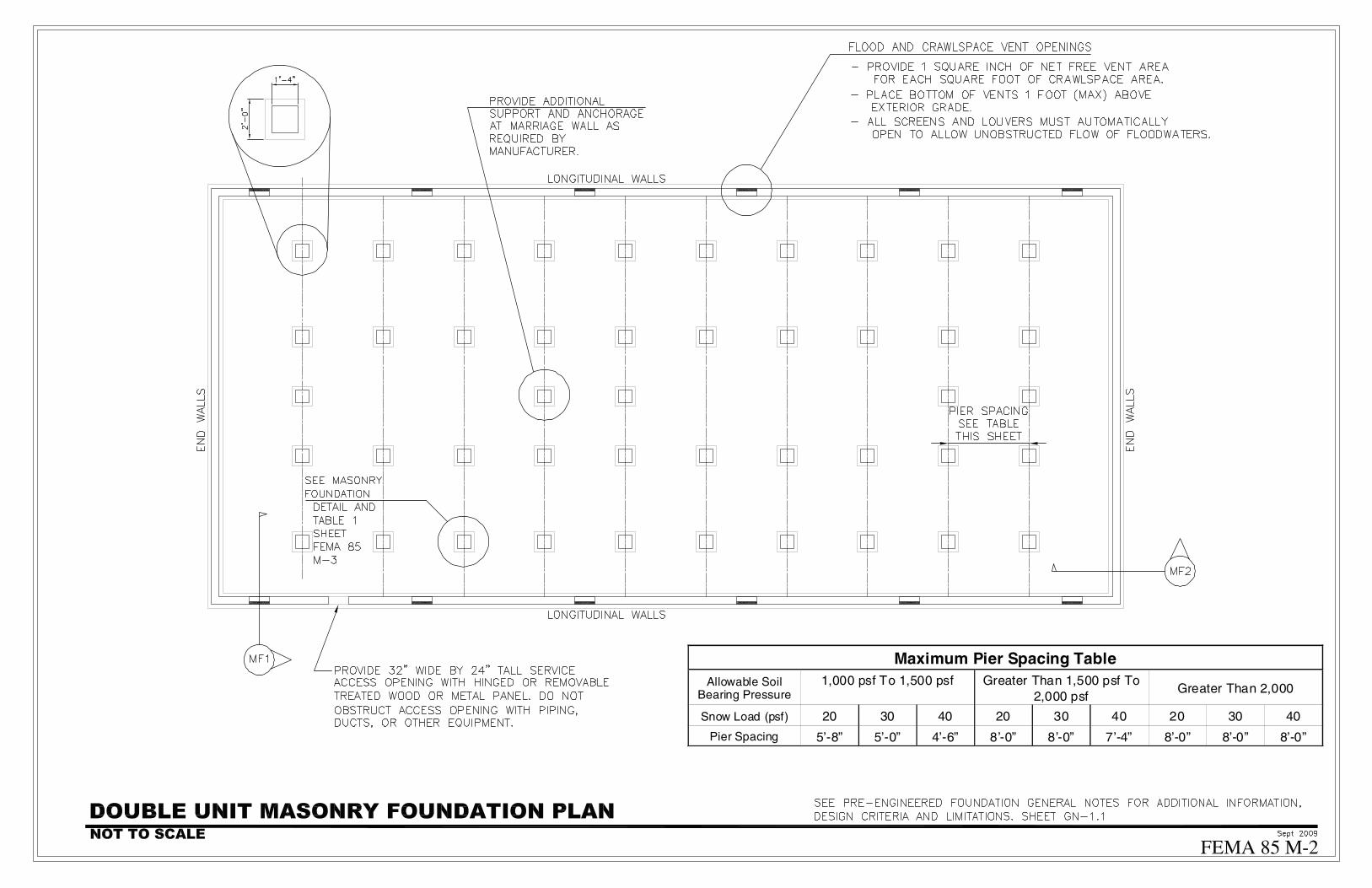
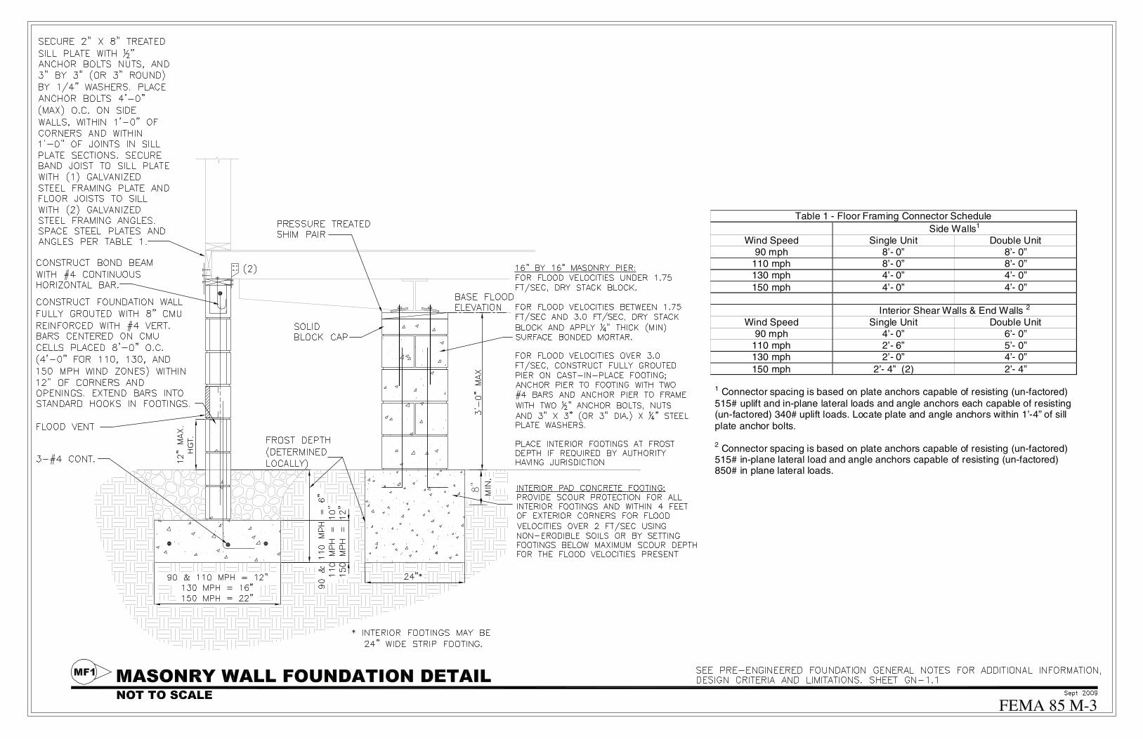
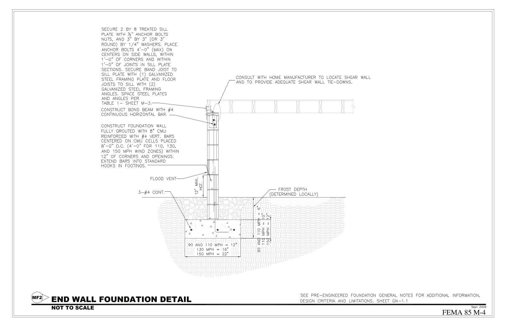
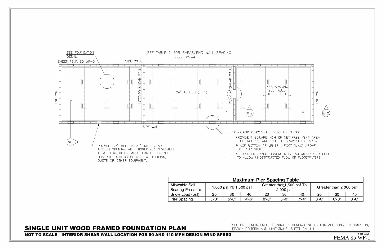

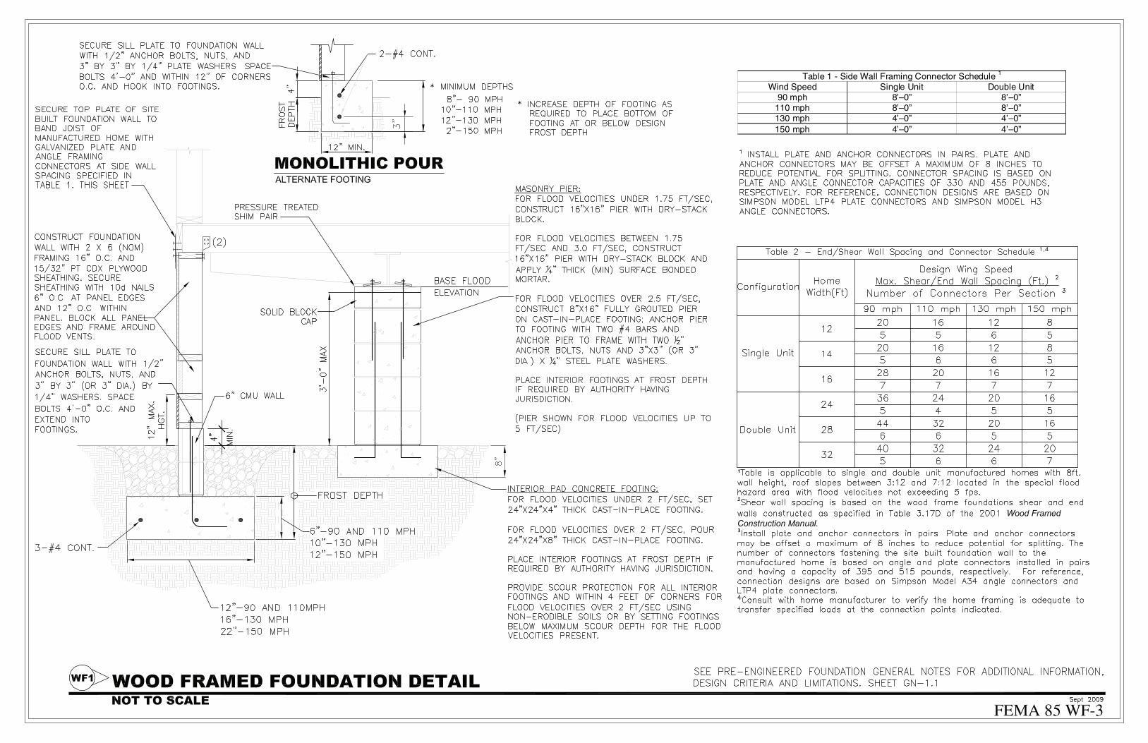
Table 1 - Side Wall Framing Connector Schedule 1
Wind Speed Single Unit Double Unit 90 mph 8’–0” 8’–0”
110 mph 8’–0” 8’–0”130 mph 4’–0” 4’–0”150 mph 4’–0” 4’–0”

Braced Masonry Pier Foundation - Pier, Footing and Tie Schedule(Minimum 1,000 lb/ft2 Soil Bearing Capacity Required)
Wind Speed
Frame Footing (W by D)
Perimeter Footing (W by D)
PierSpacing1
Wall Tie Spacing2,3
Frame Tie Spacing2,3
Single Unit
90 mph 16” by 10” Not Required 10’-0” Not
Required 8’-0”
110 mph 16” by 12” 8” by 16” 10’-0” 10’-8” 5’-4” 130 mph 16” by 12” 12” by 16” 8’-0” 8’-0” 4’-0” 150 mph 16” by 12” 12” by 24” 8’-0” 5’-4” 2’-8”
1 Locate end piers within 2’-0” of the ends of the home. 2 Wall and frame ties may be connected to a single concrete anchor. 3 Install wall and frame straps in other locations if required by the manufacturer.


P i e r S p a c i n g T a b le
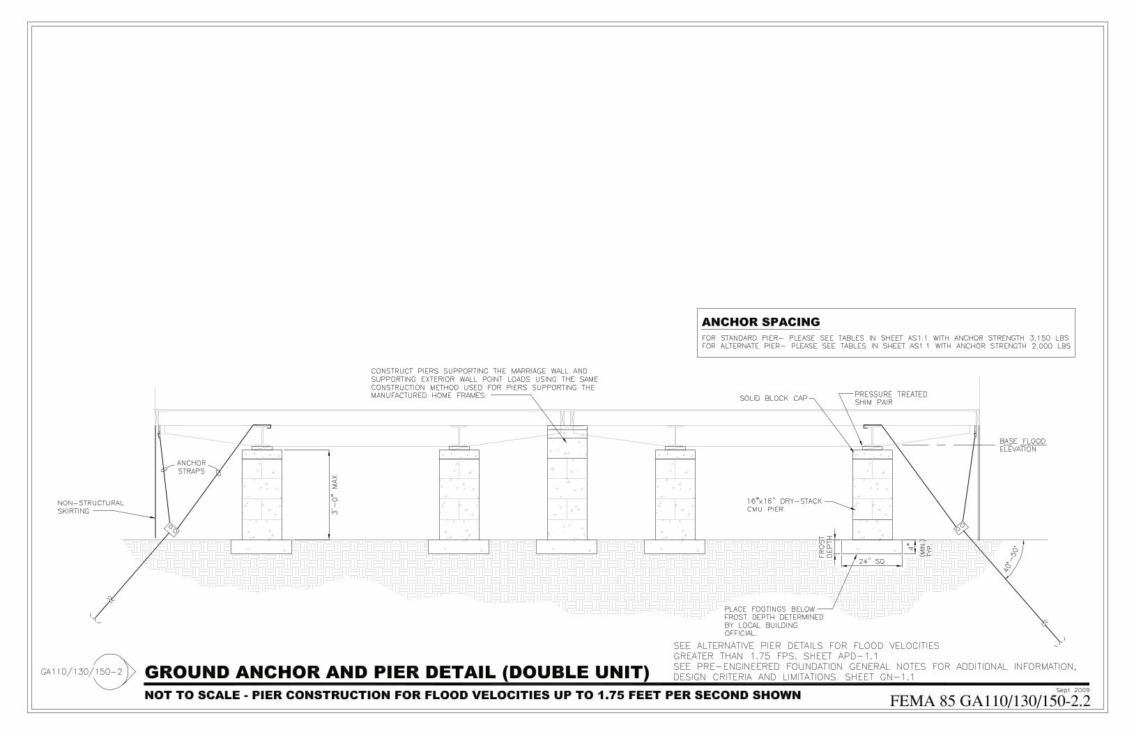
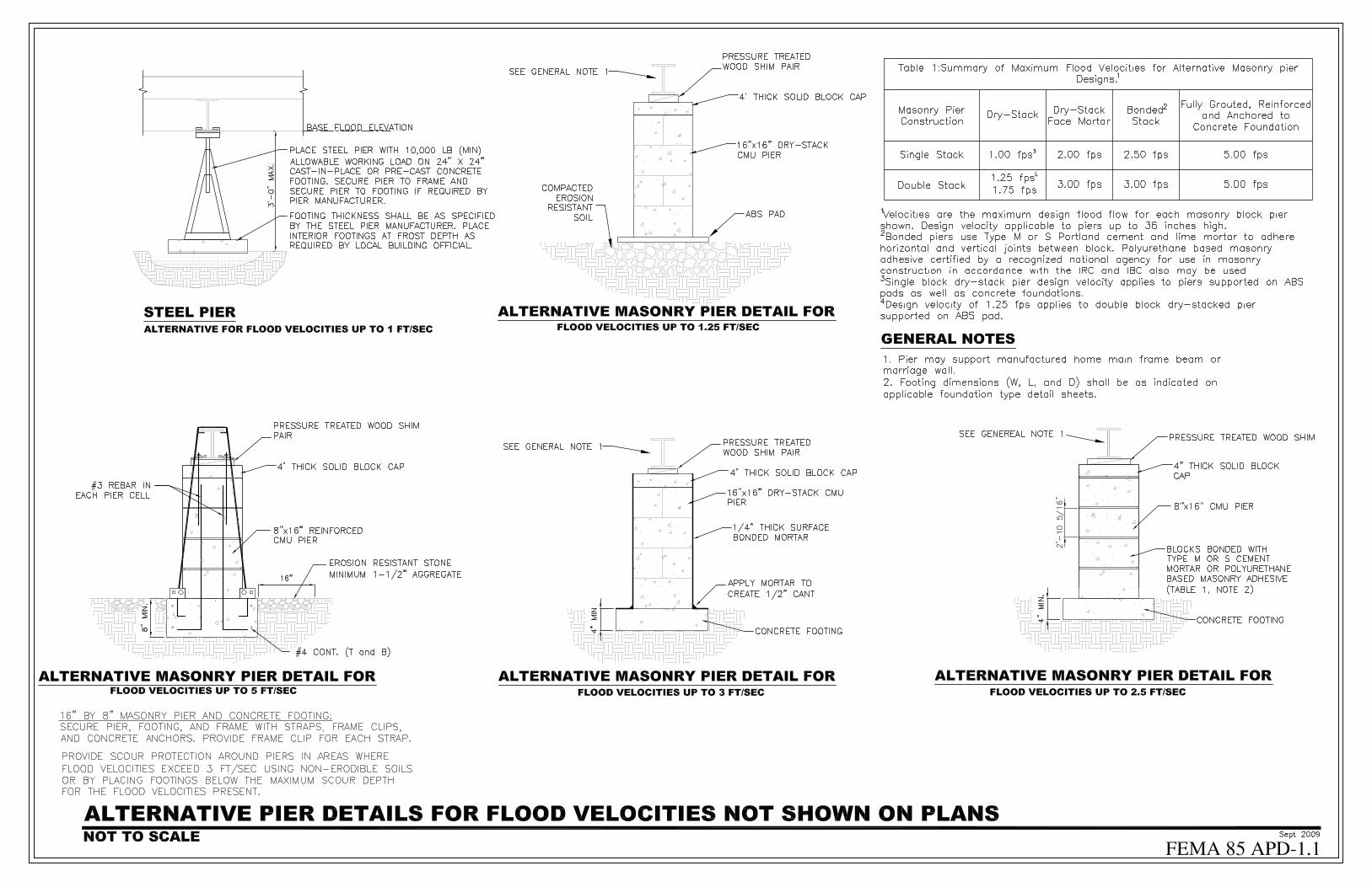

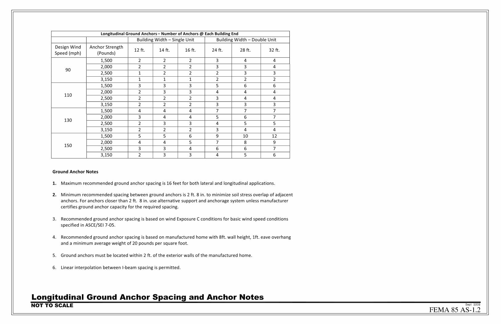


Table SP-1.2 of Pier to Chassis Seismic/Wind Anchorage Forces1
Width Pier
Height (ft)
Maximum Pier Spacing
(ft)
Horizontal Seismic/Wind Force Each
Pier (lb)
Net Seismic/Wind Uplift Force
Each Pier (lb)2
4 320 720
7 560 1250 single 3
10 800 1790
4 290 860
7 440 1510 double 3
10 600 2150
4 350 720
7 620 1250 single 5
10 880 1790
4 340 860
7 490 1510 double 5
10 650 2150
Notes 1. Listed loads are in accordance with ASCE/SEI 7 Section 2.4 Allowable Stress Design (ASD)
2. Based on 14 ft section width. Multiply by 1.15 for 16 ft section width

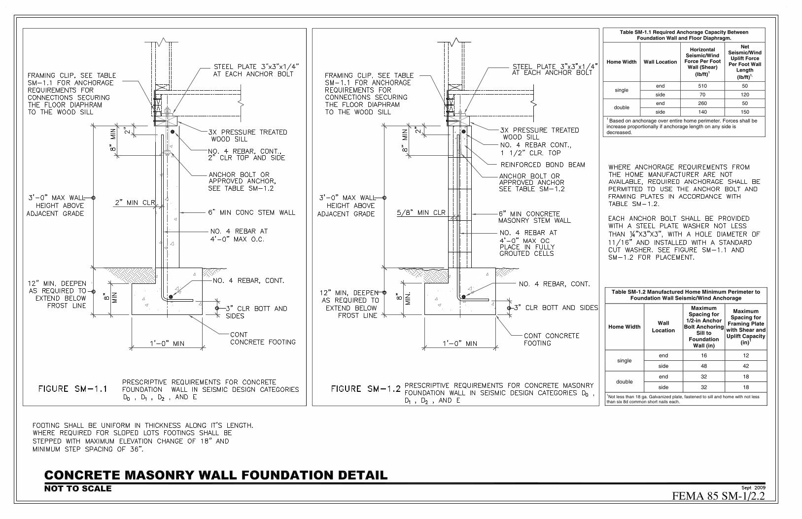
Table SM-1.1 Required Anchorage Capacity Between Foundation Wall and Floor Diaphragm.
Home Width Wall Location
Horizontal Seismic/Wind Force Per Foot
Wall (Shear) (lb/ft)1
Net Seismic/Wind Uplift Force
Per Foot Wall Length (lb/ft)1,
end 510 50 single
side 70 120
end 260 50 double
side 140 150 1 Based on anchorage over entire home perimeter. Forces shall be increase proportionally if anchorage length on any side is decreased.
Table SM-1.2 Manufactured Home Minimum Perimeter to Foundation Wall Seismic/Wind Anchorage
Home Width Wall
Location
Maximum Spacing for
1/2-in Anchor Bolt Anchoring
Sill to Foundation
Wall (in)
Maximum Spacing for
Framing Plate with Shear and Uplift Capacity
(in)1
end 16 12 single
side 48 42
end 32 18 double
side 32 18 1Not less than 18 ga. Galvanized plate, fastened to sill and home with not less than six 8d common short nails each.