gw-7552 (modbus rtu slave) example for simatic step 7 · 1 gw-7552 (modbus rtu slave) example for...
TRANSCRIPT

1
GW-7552 (Modbus RTU slave)
example for SIMATIC STEP 7
System Architecture: GW-7552 is a PROFIBUS slave and Modbus slave device.
GW-7552
14-pin screw
terminal block on
GW-7552
2
Directory
Example 1:Receives AO data from Modbus master.
Example 2: Rceives DO data from Modbus master.
Example 3: Rereshes DI data to Modbus master.
Example 4: Rereshes AI data to Modbus master.

3
Example 1: PLC receives AO data from Modbus master.
SIMATIC STEP 7 Edit
1. HW Config. – configure GW-7552 (ex: System setting module x1, Input Register—2 word module x1)
2. HW Config – Parameter assignment (ex: Com port settings, Modbus type: Slave, Modbus format:
RTU, Byte Order: Big Endian). Confirm the GW-7552’s Com Port setting is the same with MBRTU tool
(ex: baud rate-115200, data bits-8, stop bits-1, parity-none). About the MBRTU tool, please refer to the
“Communication test” in the below.
Double Click

4
3. Save and Compile
4. Download setting into STEP 7

5
5.Insert a new Organization Block (OB1,OB82,OB86)

6
6.S7 program edit
Variables used in the example LD Program:
Double Click

7
7. S7 program download
8. Make sure the RUN LED of the GW-7552 is on and the switch of the GW-7552 is at Normal mode.

8
Communication test
1. Confirm the GW-7552’s Com Port setting is the same with Modbus Master tool (ex: MBRTU, you
can download MBRTU from http://ftp.icpdas.com.tw/pub/cd/8000cd/napdos/modbus/modbus_utility/)
Com Port Settings: baud rate-115200, data bits-8, stop bits-1, parity-none
2. Click “Send Command” button to wirte AO value (0x1122, 0x3344)

9
3. PLC will receives the “AI Value (0x1122, 0x3344)” at PLC address PIW256&PIW258

10
Example 2: PLC receives DO data from Modbus master.
SIMATIC STEP 7 Edit
1. HW Config. – configure GW-7552 (ex: System setting module x1, Input Relay/Coil – 2 byte module
x1)
2. HW Config – Parameter assignment (ex: Com port settings, Modbus type: Slave, Modbus format:
RTU, Byte Order: Big Endian). Confirm the GW-7552’s Com Port setting is the same with MBRTU tool
(ex: baud rate-115200, data bits-8, stop bits-1, parity-none). About the MBRTU tool, please refer to the
“Communication test” in the below.

11
3. Save and Compile
4. Download setting into STEP 7
12
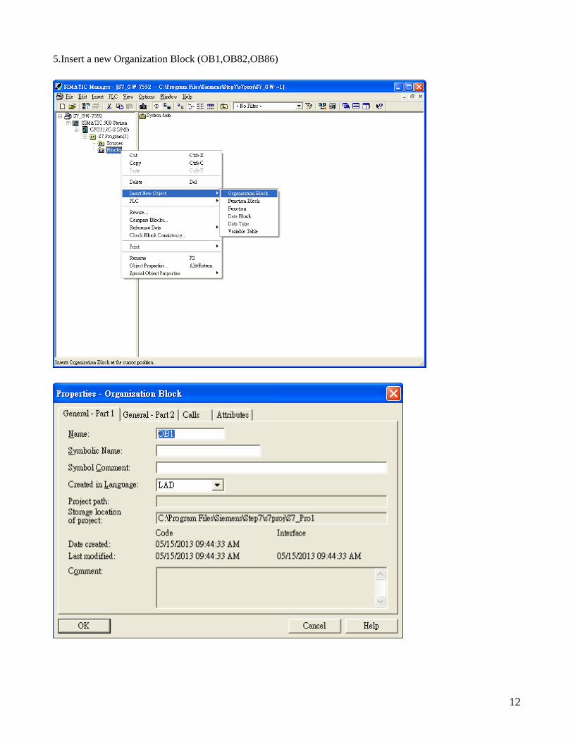
5.Insert a new Organization Block (OB1,OB82,OB86)

13
6. S7 program edit
Variables used in the example LD Program:
Double Click

14
7. S7 program download
8. Make sure the RUN LED of the GW-7552 is on and the switch of the GW-7552 is at Normal mode.

15
Communication test
1. Confirm the GW-7552’s Com Port setting is the same with Modbus Master tool (ex: MBRTU, you
can download MBRTU from http://ftp.icpdas.com.tw/pub/cd/8000cd/napdos/modbus/modbus_utility/)
Com Port Settings: baud rate-115200, data bits-8, stop bits-1, parity-none
2. Click “Send Command” button to wirte DO value (0x0102, )

16
3. PLC will receives the “DO Value (0x01, 0x02)” at PLC address IB0&IB1

17
Example 3: PLC refreshes DI data to Modbus master.
SIMATIC STEP 7 Edit
1.HW Config. – configure GW-7552 (ex: System setting module x1, Output Relay/Coil—2 byte module
x1)
2. HW Config – Parameter assignment (ex: Com port settings, Modbus type: Slave, Modbus format:
RTU, Byte Order: Big Endian). Confirm the GW-7552’s Com Port setting is the same with MBRTU tool
(ex: baud rate-115200, data bits-8, stop bits-1, parity-none). About the MBRTU tool, please refer to the
“Communication test” in the below.

18
3. Save and Compile
4. Download setting into STEP 7

19
5.Insert a new Organization Block (OB1,OB82,OB86)

20
6.S7 program edit
Variables used in the example LD Program:
Double Click

21
Using T2 trigger T1 .C1 and Tri will add 1 every 1s.

22
If Tri is equal to 256, reset counter (C1)
7. S7 program download

23
8. Make sure the RUN LED of the GW-7553 is on and the switch of the GW-7553 is at Normal mode.
Communication test
1. Confirm the Com Port setting of Modbus Master tool is the same with GW-7552’s (ex: MBRTU, you
can download MBRTU from http://ftp.icpdas.com.tw/pub/cd/8000cd/napdos/modbus/modbus_utility/)
Com Port Settings: baud rate-115200, data bits-8, stop bits-1, parity-none
24
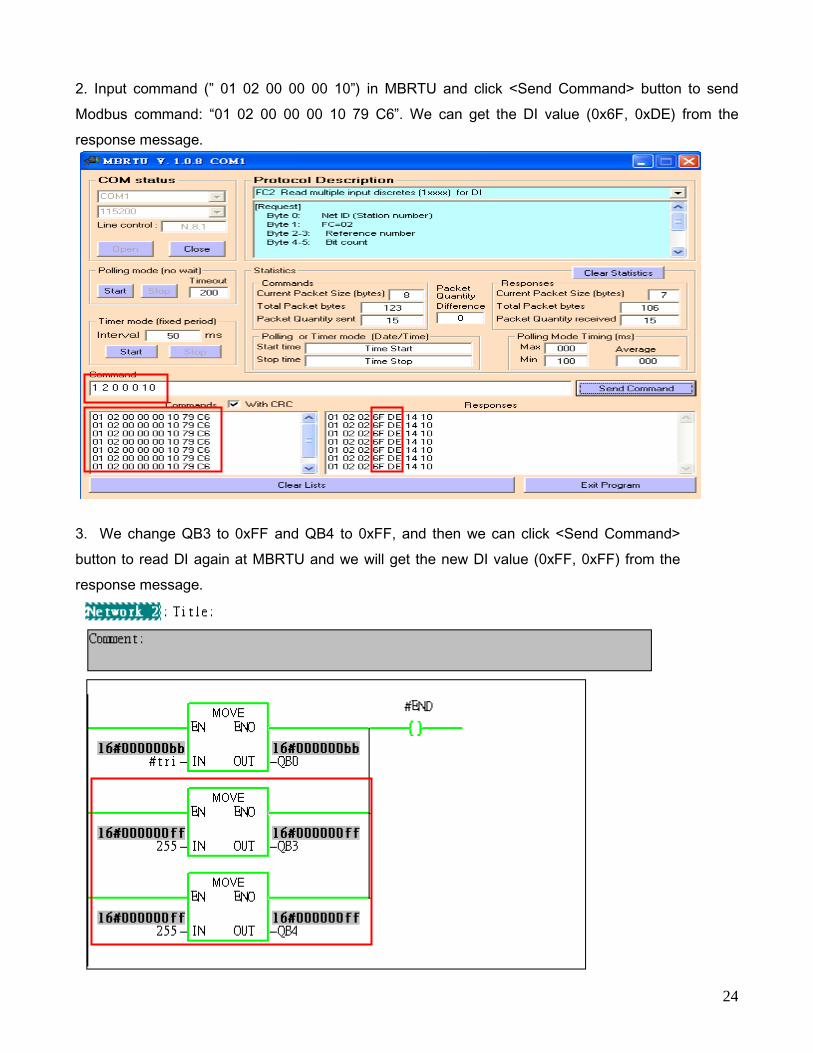
2. Input command (” 01 02 00 00 00 10”) in MBRTU and click <Send Command> button to send
Modbus command: “01 02 00 00 00 10 79 C6”. We can get the DI value (0x6F, 0xDE) from the
response message.
3. We change QB3 to 0xFF and QB4 to 0xFF, and then we can click <Send Command>
button to read DI again at MBRTU and we will get the new DI value (0xFF, 0xFF) from the
response message.

25

26
Example 4: PLC refreshes AI data to Modbus master.
SIMATIC STEP 7 Edit
1.HW Config. – configure GW-7552 (ex: System setting module x1, Output Register—2 word module
x1)
2. HW Config – Parameter assignment (ex: Com port settings, Modbus type: Slave, Modbus format:
RTU, Byte Order: Big Endian). Confirm the GW-7552’s Com Port setting is the same with MBRTU tool
(ex: baud rate-115200, data bits-8, stop bits-1, parity-none). About the MBRTU tool, please refer to the
“Communication test” in the below.

27
3. Save and Compile
4. Download setting into STEP 7

28
5.Insert a new Organization Block (OB1,OB82,OB86)

29
6.S7 program edit
Variables used in the example LD Program:
Double Click

30

31
7. S7 program download

32
8. Make sure the RUN LED of the GW-7552 is on and the switch of the GW-7552 is at Normal mode.
Communication test
1. Confirm the Com Port setting of Modbus Master tool is the same with GW-7552’s (ex: MBRTU, you
can download MBRTU from http://ftp.icpdas.com.tw/pub/cd/8000cd/napdos/modbus/modbus_utility/)
Com Port Settings: baud rate-115200, data bits-8, stop bits-1, parity-none

33
2. Input command (” 01 04 00 00 00 02”) in MBRTU and click <Send Command> button to send
Modbus command: “01 04 00 00 00 02 71 CB”. We can get the AI value (0x006F, 0x00DE) from the
response message.
3. We change PQW256 to 0x00FE and PQW258 to 0x00DC, and then we can click <Send
Command> button to read AI again at MBRTU and we will get the new AI value (0x00FE,
0x00DC) from the response message.

34