guide to tremie concrete for deep foundations - effc.org · 5.1 a new approach to specifying fresh...
TRANSCRIPT
EUROPEAN FEDERATION OF FOUNDATION CONTRACTORS
By the joint EFFC/DFI Concrete Task Group
Guide to Tremie Concrete for Deep Foundations
SECOND
2018EDITION

02
Guide to Tremie Concrete for Deep Foundations / By the joint EFFC/DFI Concrete Task Group
Karsten Beckhaus (Chairman) Bauer Spezialtiefbau, Contractor Bartho Admiraal Volker Staal en Funderingen, ContractorAndrew Bell Cementation Skanska, ContractorBjörn Böhle Keller Grundbau, Contractor Michel Boutz SGS-Intron, Consultant Dan Brown Dan Brown & Associates, Consultant Sabine Darson-Balleur Soletanche Bachy, Contractor Peter Faust Malcolm Drilling, Contractor Raffaella Granata Trevi, Contractor Chris Harnan Ceecom Consult, Consultant Duncan Moore Implenia, ContractorDuncan Nicholson ARUP, ConsultantAlexander Rostert Züblin, Contractor
EUROPEAN FEDERATION OF FOUNDATION CONTRACTORS
Francesco Biasioli European Ready-Mixed Concrete OrganizationRaymond Fassett Condon-Johnson and Associates, ContractorStephan Jefferis Environmental Geotechnics, ConsultantMartin Larisch Fletcher Construction, ContractorAntonio Marinucci V2C Strategists, ConsultantGerardo Marote Ramos Terratest, ContractorSarah Williamson Laing O’Rourke, Contractor
Jan van Dalen Technical University of DelftDimitri Feys Missouri University of Science and TechnologyClaudia Fierenkothen University of WuppertalKamal Khayat Missouri University of Science and TechnologyThomas Kränkel Technical University of MunichChenfeng Li Swansea UniversityDirk Lowke Technical University of BraunschweigNicolas Roussel French Institute of Science and Technology for Transport, Development and NetworksDaniel Weger Technical University of MunichChristopher Wilkes Cambridge University
TASK GROUP MEMBERS SPONSORED BY
CORRESPONDING MEMBERS
ACADEMIC PARTNERS
● June 2018
03
Table of Contents
Terms and Definitions
List of Abbreviations and Symbols
1. General1.1 Background1.2 Purpose and Scope
2. Design Considerations Impacting Concrete Flow2.1 General2.2 Clear Reinforcement Spacing2.3 Concrete Cover
3. Properties of Tremie Concrete3.1 General3.2 Rheology and Workability3.3 Concrete Stability
4. Concrete Mix Design4.1 Introduction4.2 Concrete Mix Design Considerations4.3 Constitutants 4.4 Proportioning and Practical Considerations
5. Specifying and Testing of Concrete, and Quality Control of Concrete Production
5.1 A New Approach to Specifying Fresh Concrete5.2 Test Methods to Characterise Fresh Concrete5.3 Suitability, Conformity and Acceptance Testing5.4 Control of Workability Retention5.5 Quality Control on the Concrete Manufacturing Process
6. Execution6.1 General6.2 Prior to Concreting6.3 Tremie Equipment6.4 Tremie Spacing6.5 Initial Concrete Placement6.6 Tremie Embedment6.7 Concrete Flow Mechanisms6.8 Flow around Reinforcement and Box-Outs6.9 Concreting Records
7. Full Scale Trials
8. Quality Control of Completed Works8.1 General8.2 Post-Construction Testing Methods
9 Numerical Modelling of Concrete Flow9.1 Introduction9.2 Studies undertaken9.3 Limitations
8
11
131414
16171718
19202122
2526262729
30
3131323334
36373738383839404242
43
454646
47484849
04
Table of Contents
Appendix A Test Methods to Characterise Fresh Concrete
Appendix B Concepts for Use of Additions
Appendix C Methods for Testing Completed Works
Appendix D Interpretation of Imperfections
Appendix E Detailed Information on Design Considerations
Appendix F Selection of Factors and Effects on Concrete Flow
References
50
58
60
62
66
75
78
05
Table of Contents
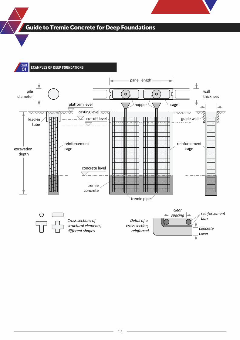
Figure 1 Examples of deep foundations
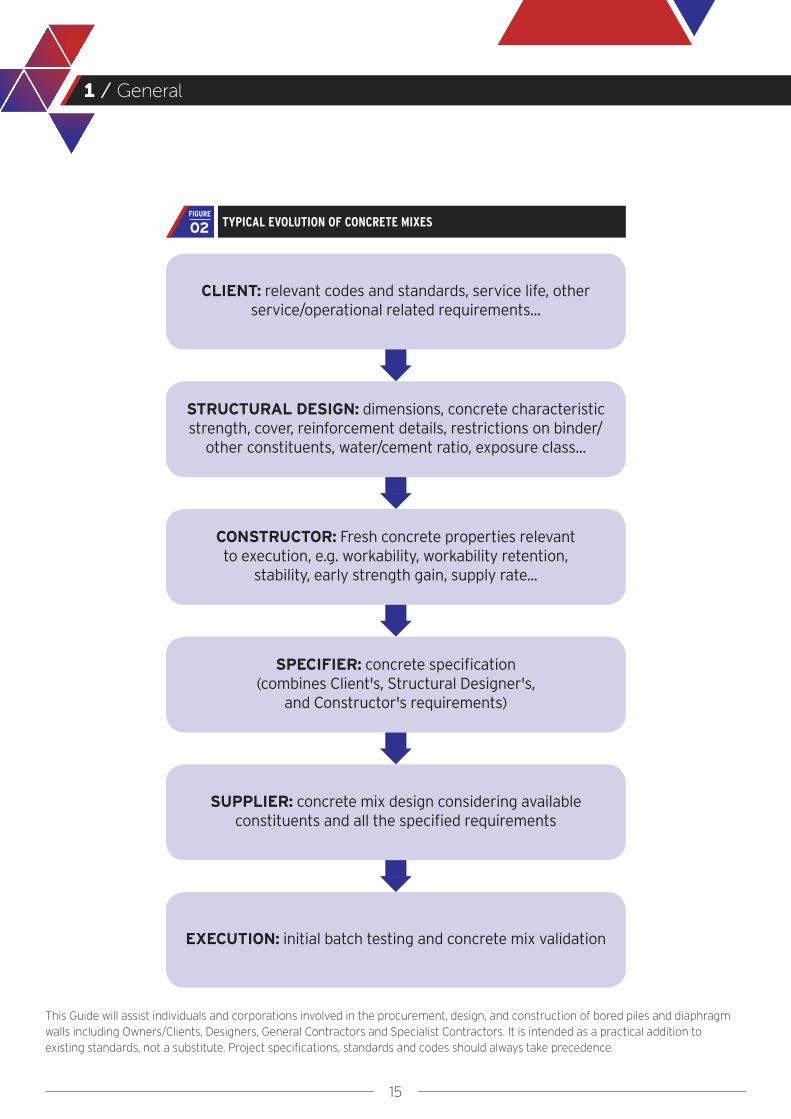
Figure 2 Typical evolution of concrete mixes
Figure 3 Concrete cover and bar spacing in deep foundations (also applicable to rectangular cages)
Figure 4 Dependencies between composition, rheology and related characteristics, and overall requirements
Figure 5 Plastic behaviour of a Bingham fluid (e.g. concrete) and a Newtonian fluid (e.g. water)
Figure 6 Qualitative comparison of rheology for different types of concrete
Figure 7 Stiffening and setting time
Figure 8 Conceptual diagram on the bleeding process in cement pastes (based on Massoussi et al, 2017), with possible interruption of bleeding due to stiffening
Figure 9 Influence of cement and other constituents on rheology (based on Wallevik, 2003)
Figure 10 Aggregate particle size distribution (grading) for 16 mm [5/8 in] maximum aggregate size, as standardised in the German National Annex DIN 1045-2 to EN 206-1
Figure 11 Slump flow curve related to yield stress and recommended range for tremie concrete (see Appendix A.1.1 and Figure 6)
Figure 12 Slump flow velocity curve related to viscosity showing the recommended range of medium viscosity for tremie concrete (test see Appendix A.1.2)
Figure 13 Extension of workability time
Figure 14 Base profile reflecting the excavation tool geometry (example shown using a cutter)
Figure 15 Phases in the tremie pour sequence
Figure 16 Schematic of bulging and plug flow
Figure 17 Cross section of a bored pile cast with differently dyed loads of tremie concrete (Böhle and Pulsfort, 2014), indicating bulging flow
Figure 18 Simulations presenting bulging flow of bulk concrete by velocity streamlines (left), and by dyed concrete following a staged lifting of the tremie pipe (Li et al, 2018)
Figure 19 Simulations presenting flow of bulk concrete in a quarter of a diaphragm wall panel, shown from the inside (to the left) and from the outside of a quarter panel, with inclusions due to rebar concentrations (images courtesy of Jan van Dalen)
12
15
18
20
21
22
22
23
27
28
31
31
33
37
39
40
41
48
49
FIGURES

06
Table of Contents
Table 1 Suitable tests for tremie concrete
Table 2 Recommendations for testing tremie concrete
Figure A.1 Test equipment for combined slump flow, slump flow velocity and VSI test
Figure A.2 Examples of visual stability index classes
Figure A.3 Equipment (example) for the modified cone outflow test
Figure A.4 Axis and vane shear cell dimensions for the manual vane shear test (New Zealand Geotechnical Society, 2001)
Figure A.5 Arrangement for static segregation test in accordance with ASTM C1610
Figure A.6 Schematic set-up to determine bleed due to gravity
Figure A.7 Test arrangement to determine water loss from pressurized fresh concrete (Bauer)
Figure A.8 Principal set-up to determine water filtrated from pressurized fresh concrete (according to Merkblatt, Weiche Betone, 2009)
Table A.1 Visual stability index VSI classes (according to ASTM C1611)
Table A.2 Classification for the hardened visual stability index (HVSI) test
Figure D.1 Examples for piles with grooves, not affecting the minimum cover for durability
Figure D.2 Examples of inclusions in a diaphragm wall and a pile (pile photo taken from Figure 9.14b, FHWA GEC10)
Figure D.3 Schematic of a concrete vent due to loss in concrete mix workability during tremie placement (according to Figure 9.13, FHWA GEC10), where an interface layer can partly be entrapped by concrete and form an inclusion
Figure D.4 Examples of channels running up the surface of a pile and a diaphragm wall
Figure D.5 Shadowing in a pile (left) and in a panel (right)
Figure D.6 Schematic showing varying degrees of mattressing
32
32
51
52
53
54
55
56
56
57
52
55
63
64
64
65
65
65
TABLES
APPENDIX A
APPENDIX D
07
Table of Contents
Figure E.1 Concrete cover in bored piles supported by a temporary casing (supplementing Figure 3)
Figure E.2 Connection details for a bored pile used to support a superstructure column
Table E.1 Commonly used reinforcement requirements for bored piles and barrettes
Table E.2 Commonly used reinforcement requirements for diaphragm walls
Table E.3 Common requirements for bond, anchorage, laps and crack width
Table F.1 Various factors and their possible effects on concrete flow and quality of deep foundations
73
74
68
70
72
76
The contents of this Guide reflect the views of the authors, who are responsible for the facts and accuracy of the data presented herein. This Guide does not constitute a standard, specification or regulation.
APPENDIX E
APPENDIX F
08
Terms and Definitions / As used in this Guide
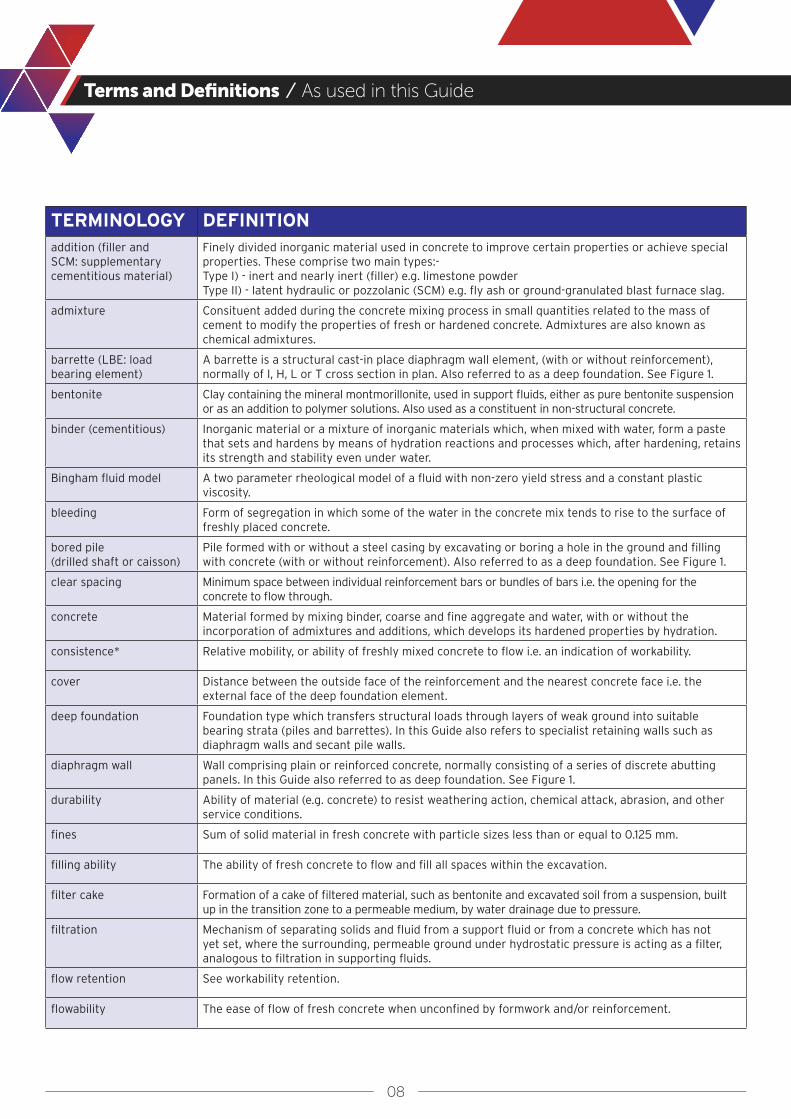
TERMINOLOGY DEFINITIONaddition (filler and SCM: supplementary cementitious material)
Finely divided inorganic material used in concrete to improve certain properties or achieve special properties. These comprise two main types:- Type I) - inert and nearly inert (filler) e.g. limestone powderType II) - latent hydraulic or pozzolanic (SCM) e.g. fly ash or ground-granulated blast furnace slag.
admixture Consituent added during the concrete mixing process in small quantities related to the mass of cement to modify the properties of fresh or hardened concrete. Admixtures are also known as chemical admixtures.
barrette (LBE: load bearing element)
A barrette is a structural cast-in place diaphragm wall element, (with or without reinforcement), normally of I, H, L or T cross section in plan. Also referred to as a deep foundation. See Figure 1.
bentonite Clay containing the mineral montmorillonite, used in support fluids, either as pure bentonite suspension or as an addition to polymer solutions. Also used as a constituent in non-structural concrete.
binder (cementitious) Inorganic material or a mixture of inorganic materials which, when mixed with water, form a paste that sets and hardens by means of hydration reactions and processes which, after hardening, retains its strength and stability even under water.
Bingham fluid model A two parameter rheological model of a fluid with non-zero yield stress and a constant plastic viscosity.
bleeding Form of segregation in which some of the water in the concrete mix tends to rise to the surface of freshly placed concrete.
bored pile (drilled shaft or caisson)
Pile formed with or without a steel casing by excavating or boring a hole in the ground and filling with concrete (with or without reinforcement). Also referred to as a deep foundation. See Figure 1.
clear spacing Minimum space between individual reinforcement bars or bundles of bars i.e. the opening for the concrete to flow through.
concrete Material formed by mixing binder, coarse and fine aggregate and water, with or without the incorporation of admixtures and additions, which develops its hardened properties by hydration.
consistence* Relative mobility, or ability of freshly mixed concrete to flow i.e. an indication of workability.
cover Distance between the outside face of the reinforcement and the nearest concrete face i.e. the external face of the deep foundation element.
deep foundation Foundation type which transfers structural loads through layers of weak ground into suitable bearing strata (piles and barrettes). In this Guide also refers to specialist retaining walls such as diaphragm walls and secant pile walls.
diaphragm wall Wall comprising plain or reinforced concrete, normally consisting of a series of discrete abutting panels. In this Guide also referred to as deep foundation. See Figure 1.
durability Ability of material (e.g. concrete) to resist weathering action, chemical attack, abrasion, and other service conditions.
fines Sum of solid material in fresh concrete with particle sizes less than or equal to 0.125 mm.
filling ability The ability of fresh concrete to flow and fill all spaces within the excavation.
filter cake Formation of a cake of filtered material, such as bentonite and excavated soil from a suspension, built up in the transition zone to a permeable medium, by water drainage due to pressure.
filtration Mechanism of separating solids and fluid from a support fluid or from a concrete which has not yet set, where the surrounding, permeable ground under hydrostatic pressure is acting as a filter, analogous to filtration in supporting fluids.
flow retention See workability retention.
flowability The ease of flow of fresh concrete when unconfined by formwork and/or reinforcement.
09
Terms and Definitions / As used in this guide
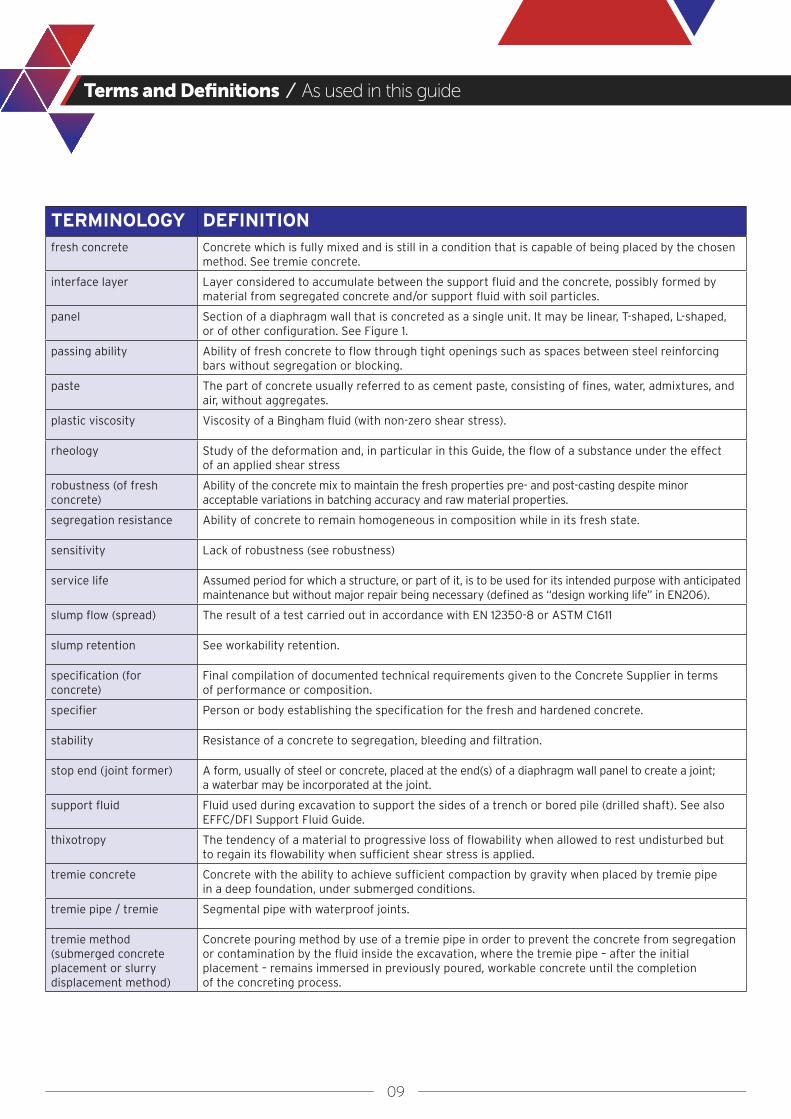
TERMINOLOGY DEFINITIONfresh concrete Concrete which is fully mixed and is still in a condition that is capable of being placed by the chosen
method. See tremie concrete.
interface layer Layer considered to accumulate between the support fluid and the concrete, possibly formed by material from segregated concrete and/or support fluid with soil particles.
panel Section of a diaphragm wall that is concreted as a single unit. It may be linear, T-shaped, L-shaped, or of other configuration. See Figure 1.
passing ability Ability of fresh concrete to flow through tight openings such as spaces between steel reinforcing bars without segregation or blocking.
paste The part of concrete usually referred to as cement paste, consisting of fines, water, admixtures, and air, without aggregates.
plastic viscosity Viscosity of a Bingham fluid (with non-zero shear stress).
rheology Study of the deformation and, in particular in this Guide, the flow of a substance under the effect of an applied shear stress
robustness (of fresh concrete)
Ability of the concrete mix to maintain the fresh properties pre- and post-casting despite minor acceptable variations in batching accuracy and raw material properties.
segregation resistance Ability of concrete to remain homogeneous in composition while in its fresh state.
sensitivity Lack of robustness (see robustness)
service life Assumed period for which a structure, or part of it, is to be used for its intended purpose with anticipated maintenance but without major repair being necessary (defined as “design working life” in EN206).
slump flow (spread) The result of a test carried out in accordance with EN 12350-8 or ASTM C1611
slump retention See workability retention.
specification (for concrete)
Final compilation of documented technical requirements given to the Concrete Supplier in terms of performance or composition.
specifier Person or body establishing the specification for the fresh and hardened concrete.
stability Resistance of a concrete to segregation, bleeding and filtration.
stop end (joint former) A form, usually of steel or concrete, placed at the end(s) of a diaphragm wall panel to create a joint; a waterbar may be incorporated at the joint.
support fluid Fluid used during excavation to support the sides of a trench or bored pile (drilled shaft). See also EFFC/DFI Support Fluid Guide.
thixotropy The tendency of a material to progressive loss of flowability when allowed to rest undisturbed but to regain its flowability when sufficient shear stress is applied.
tremie concrete Concrete with the ability to achieve sufficient compaction by gravity when placed by tremie pipe in a deep foundation, under submerged conditions.
tremie pipe / tremie Segmental pipe with waterproof joints.
tremie method (submerged concrete placement or slurry displacement method)
Concrete pouring method by use of a tremie pipe in order to prevent the concrete from segregation or contamination by the fluid inside the excavation, where the tremie pipe – after the initial placement – remains immersed in previously poured, workable concrete until the completion of the concreting process.
10
Terms and Definitions / As used in this guide
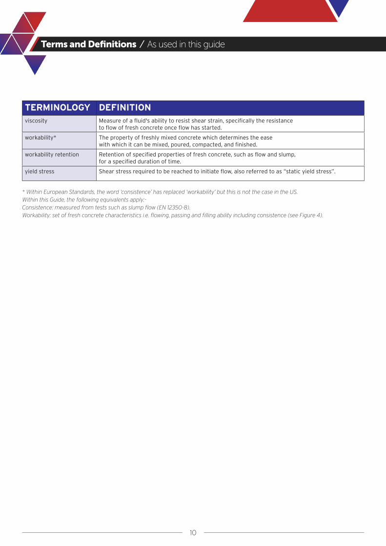
TERMINOLOGY DEFINITIONviscosity Measure of a fluid's ability to resist shear strain, specifically the resistance
to flow of fresh concrete once flow has started.
workability* The property of freshly mixed concrete which determines the ease with which it can be mixed, poured, compacted, and finished.
workability retention Retention of specified properties of fresh concrete, such as flow and slump, for a specified duration of time.
yield stress Shear stress required to be reached to initiate flow, also referred to as “static yield stress”.
* Within European Standards, the word ‘consistence’ has replaced ‘workability’ but this is not the case in the US. Within this Guide, the following equivalents apply:-Consistence: measured from tests such as slump flow (EN 12350-8).Workability: set of fresh concrete characteristics i.e. flowing, passing and filling ability including consistence (see Figure 4).

11
List of Abbreviations and Symbols
AASHTOACI
ADSC-IAFDAFNOR
APIASTMCENCIA
CIRIADAfStb
DINDFI
ECPCEFFCEN
EPCCFHWA
GGBS/GGBFSICEISOÖBV
QA/QCR & DSCCVSIa
cmin
cnom
Δcdev
Δdc
db-t
dspacer
DDc
Dfinal
Dmax
Dnom
Ds
Ds,n
DT
ηh1/h2
hc
hc,T
hF
kμpi,T
po/pi
sT
tfinal
τ τ0
American Association of State and Highway Transportation OfficialsAmerican Concrete InstituteThe International Association of Foundation Drilling Association Francaise de NormalisationAmerican Petroleum InstituteASTM InternationalEuropean Committee for StandardizationConcrete Institute of AustraliaConstruction Industry Research and Information Association (UK organisation)Deutscher Ausschuss für Stahlbeton (German Committee for Structural Concrete)Deutsches Institut für Normung (German Institute for Standardization)Deep Foundations InstituteEquivalent Concrete Performance ConceptEuropean Federation of Foundation ContractorsEuropean NormEquivalent Performance of Combinations ConceptFederal Highway AdministrationGround granulated blast furnace slagInstitution of Civil Engineers (UK Professional Body)International Organization for Standardization Österreichische Bautechnik Vereinigung (en: Austrian Society for Construction Technology)Quality Assurance/Quality ControlResearch and DevelopmentSelf-Compacting ConcreteVisual Stability Indexminimum clear spacing between reinforcement barsminimum concrete cover according to structural or execution requirementsnominal concrete cover = cmin + Δcdev (to be considered in design)allowance in design for construction toleranceadditional allowance in reinforcement cage design for installationdistance from bottom of excavation to tremie pipe outlethorizontal dimension of the spacer (perpendicular to reinforcement cage)dimension (diameter or thickness) of excavation or concrete elementouter dimension of the reinforcement cagediameter of the final spread of the concrete achieved in a slump flow testmaximum nominal upper aggregate size nominal excavation dimension, defined by excavation tool dimensionsreinforcement bar diametersubstitute diameter for a bundle of ‘n’ reinforcement bars internal diameter of tremie pipedynamic viscosityembedment of tremie pipe before (h1) and after (h2) tremie pipe is cutconcrete level in excavationconcrete level in tremie pipe (= hydrostatic balance point)fluid level in excavationfactor which takes into account the activity of a Type II additionplastic viscosityhydrostatic pressure inside tremie pipehydrostatic pressure outside (po) and inside (pi) the excavationsection length of tremie pipe section to cut time for concrete to reach final spread in slump flow testshear stressyield stressshear rate
12
Guide to Tremie Concrete for Deep Foundations
EXAMPLES OF DEEP FOUNDATIONS01FIGURE

13
General
Section 1
14
1 / General
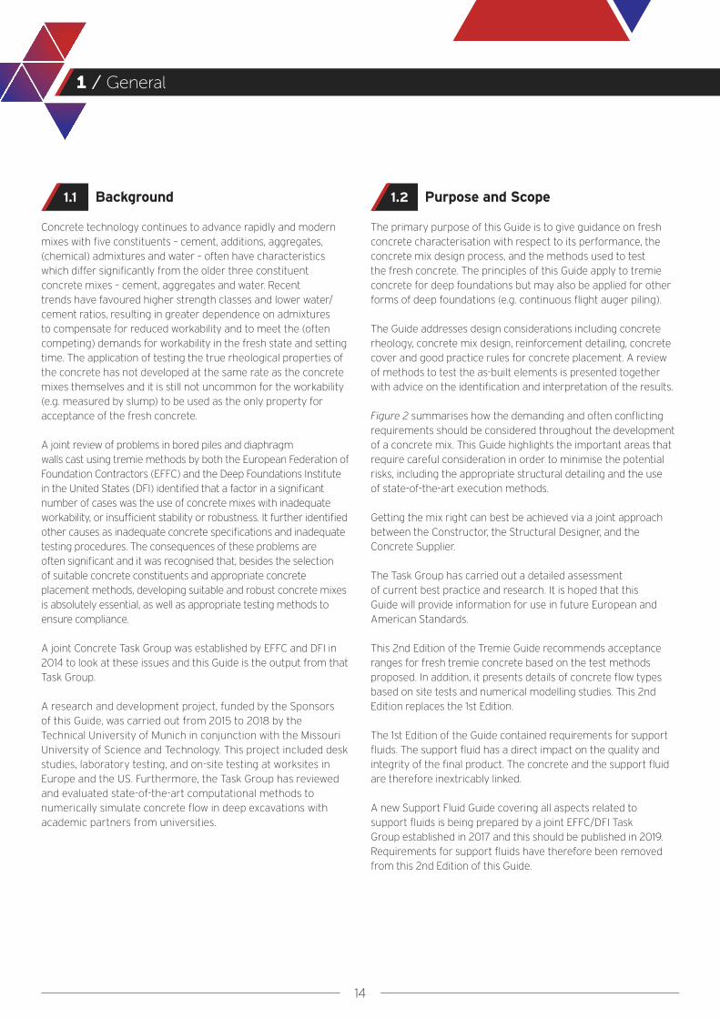
Background
Concrete technology continues to advance rapidly and modern mixes with five constituents – cement, additions, aggregates, (chemical) admixtures and water – often have characteristics which differ significantly from the older three constituent concrete mixes – cement, aggregates and water. Recent trends have favoured higher strength classes and lower water/cement ratios, resulting in greater dependence on admixtures to compensate for reduced workability and to meet the (often competing) demands for workability in the fresh state and setting time. The application of testing the true rheological properties of the concrete has not developed at the same rate as the concrete mixes themselves and it is still not uncommon for the workability (e.g. measured by slump) to be used as the only property for acceptance of the fresh concrete.
A joint review of problems in bored piles and diaphragm walls cast using tremie methods by both the European Federation of Foundation Contractors (EFFC) and the Deep Foundations Institute in the United States (DFI) identified that a factor in a significant number of cases was the use of concrete mixes with inadequate workability, or insufficient stability or robustness. It further identified other causes as inadequate concrete specifications and inadequate testing procedures. The consequences of these problems are often significant and it was recognised that, besides the selection of suitable concrete constituents and appropriate concrete placement methods, developing suitable and robust concrete mixes is absolutely essential, as well as appropriate testing methods to ensure compliance.
A joint Concrete Task Group was established by EFFC and DFI in 2014 to look at these issues and this Guide is the output from that Task Group.
A research and development project, funded by the Sponsors of this Guide, was carried out from 2015 to 2018 by the Technical University of Munich in conjunction with the Missouri University of Science and Technology. This project included desk studies, laboratory testing, and on-site testing at worksites in Europe and the US. Furthermore, the Task Group has reviewed and evaluated state-of-the-art computational methods to numerically simulate concrete flow in deep excavations with academic partners from universities.
Purpose and Scope
The primary purpose of this Guide is to give guidance on fresh concrete characterisation with respect to its performance, the concrete mix design process, and the methods used to test the fresh concrete. The principles of this Guide apply to tremie concrete for deep foundations but may also be applied for other forms of deep foundations (e.g. continuous flight auger piling).
The Guide addresses design considerations including concrete rheology, concrete mix design, reinforcement detailing, concrete cover and good practice rules for concrete placement. A review of methods to test the as-built elements is presented together with advice on the identification and interpretation of the results.
Figure 2 summarises how the demanding and often conflicting requirements should be considered throughout the development of a concrete mix. This Guide highlights the important areas that require careful consideration in order to minimise the potential risks, including the appropriate structural detailing and the use of state-of-the-art execution methods.
Getting the mix right can best be achieved via a joint approach between the Constructor, the Structural Designer, and the Concrete Supplier.
The Task Group has carried out a detailed assessment of current best practice and research. It is hoped that this Guide will provide information for use in future European and American Standards.
This 2nd Edition of the Tremie Guide recommends acceptance ranges for fresh tremie concrete based on the test methods proposed. In addition, it presents details of concrete flow types based on site tests and numerical modelling studies. This 2nd Edition replaces the 1st Edition.
The 1st Edition of the Guide contained requirements for support fluids. The support fluid has a direct impact on the quality and integrity of the final product. The concrete and the support fluid are therefore inextricably linked.
A new Support Fluid Guide covering all aspects related to support fluids is being prepared by a joint EFFC/DFI Task Group established in 2017 and this should be published in 2019. Requirements for support fluids have therefore been removed from this 2nd Edition of this Guide.
1.1 1.2
15
1 / General
This Guide will assist individuals and corporations involved in the procurement, design, and construction of bored piles and diaphragm walls including Owners/Clients, Designers, General Contractors and Specialist Contractors. It is intended as a practical addition to existing standards, not a substitute. Project specifications, standards and codes should always take precedence.
SUPPLIER: concrete mix design considering available constituents and all the specified requirements
EXECUTION: initial batch testing and concrete mix validation
CONSTRUCTOR: Fresh concrete properties relevant to execution, e.g. workability, workability retention,
stability, early strength gain, supply rate...
SPECIFIER: concrete specification (combines Client's, Structural Designer's,
and Constructor's requirements)
CLIENT: relevant codes and standards, service life, other service/operational related requirements...
STRUCTURAL DESIGN: dimensions, concrete characteristic strength, cover, reinforcement details, restrictions on binder/
other constituents, water/cement ratio, exposure class...
TYPICAL EVOLUTION OF CONCRETE MIXES02FIGURE
16
Design Considerations Impacting Concrete Flow
Section 2
17
2 / Design Considerations Impacting Concrete Flow
General
The structural design of deep foundations is a specialist subject requiring both structural and geotechnical input, as it must also consider the conditions for the execution of the deep foundation works. This section is limited to structural detailing and the impact of the reinforcement cage on the flow of the concrete through the reinforcement bars into the cover zone embedding the bars. The impact of concrete placement on end bearing and shaft friction is not considered in this Guide and reference should be made to Eurocode 7 (EN 1997-1) or relevant US standards e.g. FHWA GEC10.
With regards to the reinforcement detailing, the ideal situation for tremie concrete placement is for there to be no obstructions to concrete flow. Unfortunately the reinforcement cage, including spacer blocks and box-outs (when used), represents a major obstruction to flow. The structural design, including the design of the reinforcement cage, therefore has a significant effect on the quality of the finished element.
The following sections give good practice recommendations for clear reinforcement spacing and cover. The Structural Designer of the reinforcement cage should consider the requirements for successful concrete placement specific to their design as well as the minimum general requirements given in Standards i.e. the structural design must meet the needs of the designer plus the constructor in exactly the same way as the concrete mix design. This may require the designer to seek specialist advice.
Clear Reinforcement Spacing
The clear reinforcement spacing (shown as ‘a’ in Figure 3) must be assessed by the Structural Designer based on the structural requirements and the ability of the concrete to flow through the horizontal and vertical bars of the reinforcement cage.
According to Eurocode 2 (EN 1992-1) the structurally required clear spacing between vertical bars or bundles of bars should be double their diameter Ds or nominal diameter Ds,n (see Table E.1 in Appendix E).
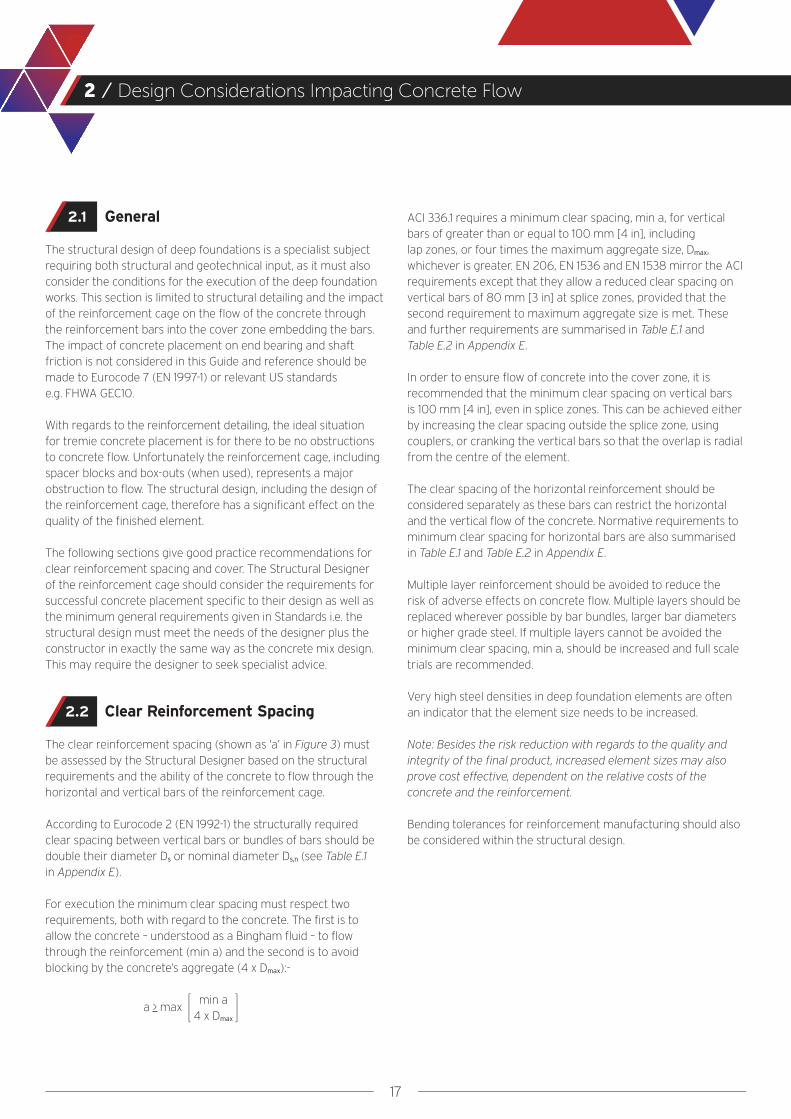
For execution the minimum clear spacing must respect two requirements, both with regard to the concrete. The first is to allow the concrete – understood as a Bingham fluid – to flow through the reinforcement (min a) and the second is to avoid blocking by the concrete’s aggregate (4 x Dmax):-
ACI 336.1 requires a minimum clear spacing, min a, for vertical bars of greater than or equal to 100 mm [4 in], including lap zones, or four times the maximum aggregate size, Dmax, whichever is greater. EN 206, EN 1536 and EN 1538 mirror the ACI requirements except that they allow a reduced clear spacing on vertical bars of 80 mm [3 in] at splice zones, provided that the second requirement to maximum aggregate size is met. These and further requirements are summarised in Table E.1 and Table E.2 in Appendix E.
In order to ensure flow of concrete into the cover zone, it is recommended that the minimum clear spacing on vertical bars is 100 mm [4 in], even in splice zones. This can be achieved either by increasing the clear spacing outside the splice zone, using couplers, or cranking the vertical bars so that the overlap is radial from the centre of the element.
The clear spacing of the horizontal reinforcement should be considered separately as these bars can restrict the horizontal and the vertical flow of the concrete. Normative requirements to minimum clear spacing for horizontal bars are also summarised in Table E.1 and Table E.2 in Appendix E.
Multiple layer reinforcement should be avoided to reduce the risk of adverse effects on concrete flow. Multiple layers should be replaced wherever possible by bar bundles, larger bar diameters or higher grade steel. If multiple layers cannot be avoided the minimum clear spacing, min a, should be increased and full scale trials are recommended.
Very high steel densities in deep foundation elements are often an indicator that the element size needs to be increased.
Note: Besides the risk reduction with regards to the quality and integrity of the final product, increased element sizes may also prove cost effective, dependent on the relative costs of the concrete and the reinforcement.
Bending tolerances for reinforcement manufacturing should also be considered within the structural design.
2.1
2.2
a > maxmin a
4 x Dmax

18
2 / Design Considerations Impacting Concrete Flow
Concrete Cover
Regarding the concrete cover for deep foundations, there are two independent requirements to be considered at the design stage. The first requirement covers the need for a certain concrete cover during the structure’s service life and the second is the need for a minimum concrete cover during execution to allow for concrete flow and the removal of temporary casing. These two approaches are independent and therefore not necessarily compatible.
For both requirements, the designer should specify a nominal cover, cnom, based on a minimum cover, cmin, plus an allowance for construction tolerances, Δcdev, as shown in Figure 3.
For execution, a nominal concrete cover of at least 75 mm [3 in] is recommended, which takes into account a minimum cover (cmin) of 50 mm [2 in] and an allowance for construction tolerances (Δcdev) of 25 mm [1 in]. In most cases, the minimum nominal cover for execution will exceed those derived from structural and durability requirements.
Note: In Appendix E the present variation of normative rules is discussed in detail. EN 1536 and the FHWA GEC 10 also identify particular instances where the minimum nominal cover must or should be increased.
Spacers are usually detailed to cover the design nominal cover. It should also be recognised that an additional tolerance, Δdc, should be considered in the cage design to allow the installation of the cage into the excavation (see Figure 3):
Note: The specific case of a bored pile constructed using a temporary casing is shown and discussed in Appendix E.
2.3
CONCRETE COVER AND BAR SPACING IN DEEP FOUNDATIONS (ALSO APPLICABLE TO RECTANGULAR CAGES)03
FIGURE
cnom = cmin + Δcdev with cmin > maxcmin, structural
cmin, execution
Dc = Dnom - 2 cnom - 2 Δdc

19
Properties of Tremie Concrete
Section 3
20
3 / Properties of Tremie Concrete
General
The rheology of concrete is fundamental to its behaviour during casting. Rheology determines the success of concrete placement and the quality of the final product i.e. durability is a direct function of rheology.
The key rheological characteristics for fresh concrete are:-
● Workability (the general term defining the ability of the concrete to fill the excavation, self-levelling and self-compacting under gravity)
● Workability retention (defining how long the specified fresh properties will be retained)
● Stability (resistance to segregation, bleeding and filtration)
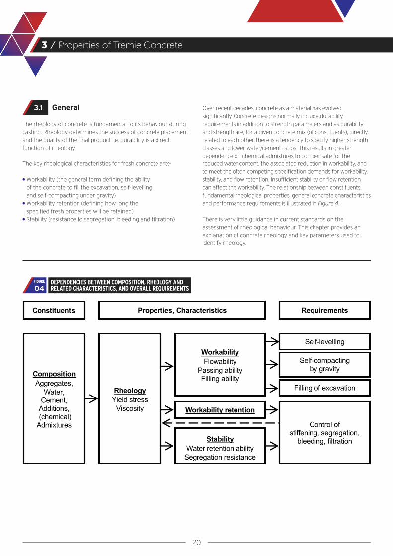
Over recent decades, concrete as a material has evolved significantly. Concrete designs normally include durability requirements in addition to strength parameters and as durability and strength are, for a given concrete mix (of constituents), directly related to each other, there is a tendency to specify higher strength classes and lower water/cement ratios. This results in greater dependence on chemical admixtures to compensate for the reduced water content, the associated reduction in workability, and to meet the often competing specification demands for workability, stability, and flow retention. Insufficient stability or flow retention can affect the workability. The relationship between constituents, fundamental rheological properties, general concrete characteristics and performance requirements is illustrated in Figure 4.
There is very little guidance in current standards on the assessment of rheological behaviour. This chapter provides an explanation of concrete rheology and key parameters used to identify rheology.
3.1
DEPENDENCIES BETWEEN COMPOSITION, RHEOLOGY AND RELATED CHARACTERISTICS, AND OVERALL REQUIREMENTS04
FIGURE
21
3 / Properties of Tremie Concrete
Rheology and Workability
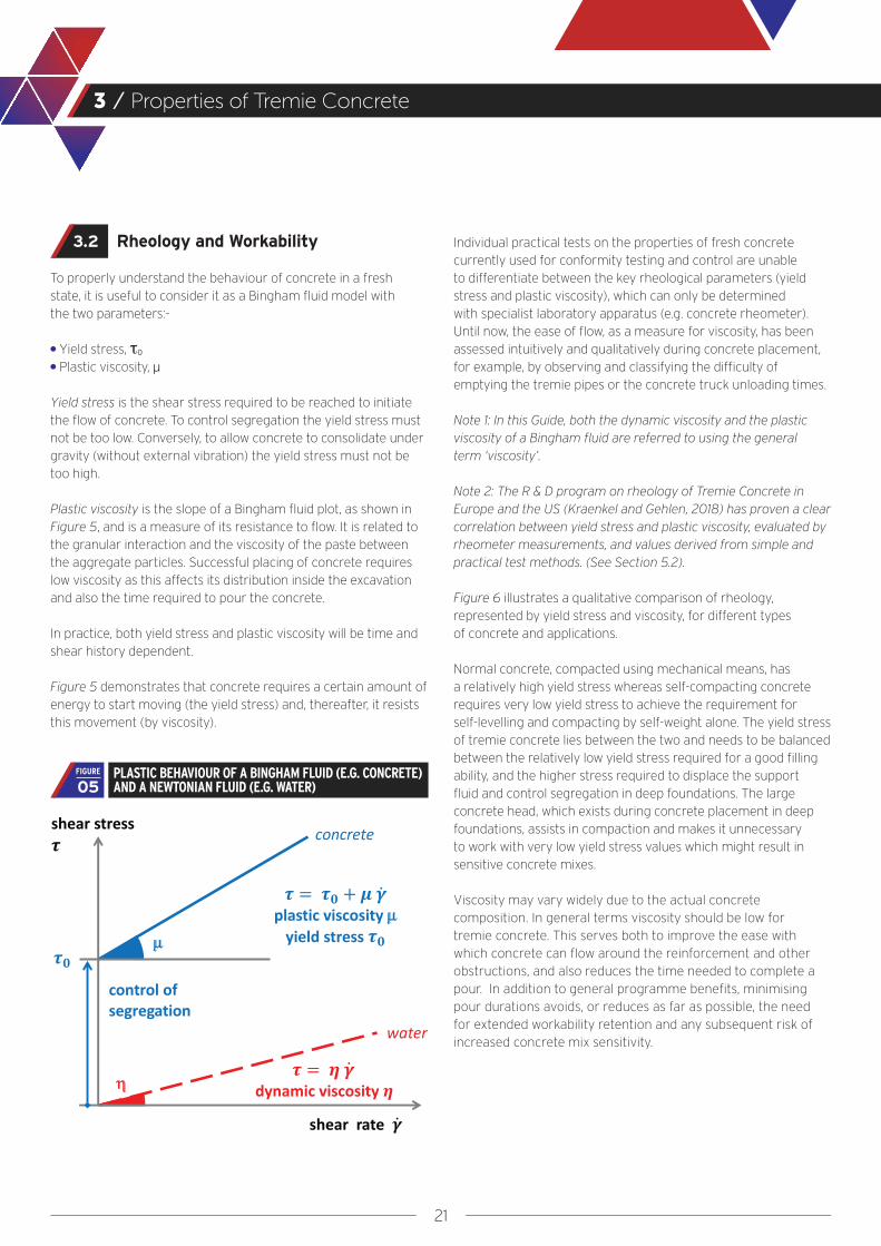
To properly understand the behaviour of concrete in a fresh state, it is useful to consider it as a Bingham fluid model with the two parameters:-
● Yield stress, τ0
● Plastic viscosity, μ
Yield stress is the shear stress required to be reached to initiate the flow of concrete. To control segregation the yield stress must not be too low. Conversely, to allow concrete to consolidate under gravity (without external vibration) the yield stress must not be too high.
Plastic viscosity is the slope of a Bingham fluid plot, as shown in Figure 5, and is a measure of its resistance to flow. It is related to the granular interaction and the viscosity of the paste between the aggregate particles. Successful placing of concrete requires low viscosity as this affects its distribution inside the excavation and also the time required to pour the concrete.
In practice, both yield stress and plastic viscosity will be time and shear history dependent.
Figure 5 demonstrates that concrete requires a certain amount of energy to start moving (the yield stress) and, thereafter, it resists this movement (by viscosity).
Individual practical tests on the properties of fresh concrete currently used for conformity testing and control are unable to differentiate between the key rheological parameters (yield stress and plastic viscosity), which can only be determined with specialist laboratory apparatus (e.g. concrete rheometer). Until now, the ease of flow, as a measure for viscosity, has been assessed intuitively and qualitatively during concrete placement, for example, by observing and classifying the difficulty of emptying the tremie pipes or the concrete truck unloading times.
Note 1: In this Guide, both the dynamic viscosity and the plastic viscosity of a Bingham fluid are referred to using the general term ‘viscosity’.
Note 2: The R & D program on rheology of Tremie Concrete in Europe and the US (Kraenkel and Gehlen, 2018) has proven a clear correlation between yield stress and plastic viscosity, evaluated by rheometer measurements, and values derived from simple and practical test methods. (See Section 5.2).
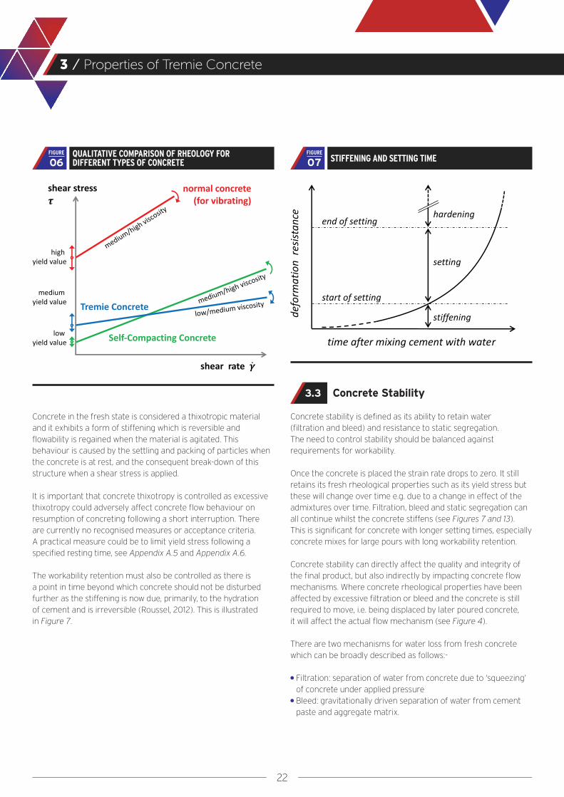
Figure 6 illustrates a qualitative comparison of rheology, represented by yield stress and viscosity, for different types of concrete and applications.
Normal concrete, compacted using mechanical means, has a relatively high yield stress whereas self-compacting concrete requires very low yield stress to achieve the requirement for self-levelling and compacting by self-weight alone. The yield stress of tremie concrete lies between the two and needs to be balanced between the relatively low yield stress required for a good filling ability, and the higher stress required to displace the support fluid and control segregation in deep foundations. The large concrete head, which exists during concrete placement in deep foundations, assists in compaction and makes it unnecessary to work with very low yield stress values which might result in sensitive concrete mixes.
Viscosity may vary widely due to the actual concrete composition. In general terms viscosity should be low for tremie concrete. This serves both to improve the ease with which concrete can flow around the reinforcement and other obstructions, and also reduces the time needed to complete a pour. In addition to general programme benefits, minimising pour durations avoids, or reduces as far as possible, the need for extended workability retention and any subsequent risk of increased concrete mix sensitivity.
3.2
PLASTIC BEHAVIOUR OF A BINGHAM FLUID (E.G. CONCRETE) AND A NEWTONIAN FLUID (E.G. WATER)05
FIGURE
22
3 / Properties of Tremie Concrete
Concrete in the fresh state is considered a thixotropic material and it exhibits a form of stiffening which is reversible and flowability is regained when the material is agitated. This behaviour is caused by the settling and packing of particles when the concrete is at rest, and the consequent break-down of this structure when a shear stress is applied.
It is important that concrete thixotropy is controlled as excessive thixotropy could adversely affect concrete flow behaviour on resumption of concreting following a short interruption. There are currently no recognised measures or acceptance criteria. A practical measure could be to limit yield stress following a specified resting time, see Appendix A.5 and Appendix A.6.
The workability retention must also be controlled as there is a point in time beyond which concrete should not be disturbed further as the stiffening is now due, primarily, to the hydration of cement and is irreversible (Roussel, 2012). This is illustrated in Figure 7.
Concrete Stability
Concrete stability is defined as its ability to retain water (filtration and bleed) and resistance to static segregation. The need to control stability should be balanced against requirements for workability.
Once the concrete is placed the strain rate drops to zero. It still retains its fresh rheological properties such as its yield stress but these will change over time e.g. due to a change in effect of the admixtures over time. Filtration, bleed and static segregation can all continue whilst the concrete stiffens (see Figures 7 and 13). This is significant for concrete with longer setting times, especially concrete mixes for large pours with long workability retention.
Concrete stability can directly affect the quality and integrity of the final product, but also indirectly by impacting concrete flow mechanisms. Where concrete rheological properties have been affected by excessive filtration or bleed and the concrete is still required to move, i.e. being displaced by later poured concrete, it will affect the actual flow mechanism (see Figure 4). There are two mechanisms for water loss from fresh concrete which can be broadly described as follows:-
● Filtration: separation of water from concrete due to ‘squeezing’ of concrete under applied pressure
● Bleed: gravitationally driven separation of water from cement paste and aggregate matrix.
3.3
QUALITATIVE COMPARISON OF RHEOLOGY FOR DIFFERENT TYPES OF CONCRETE06
FIGURESTIFFENING AND SETTING TIME07
FIGURE

23
3 / Properties of Tremie Concrete
In practice some water loss from fresh concrete will always occur and is likely to be as a result of a combination of these mechanisms. Given that segregation cannot be totally eliminated, it is essential to understand both mechanisms in order to balance stability issues with workability. Further detail on filtration, bleed and static segregation are provided below. Section 4 of this Guide covering Concrete Mix Design outlines measures that can be taken to minimise stability issues.
Filtration
Fresh concrete in deep foundations is subject to high head pressures which in turn lead to high pore-water pressures in the fresh concrete, increasing with depth. These concrete pore-water pressures can be much higher than the water pressures in the surrounding ground. A hydraulic gradient develops and this leads to water flow out of the concrete. The effect of this water loss is to stiffen the concrete i.e. to change the rheological properties to higher yield stress and higher viscosity.
Filtration can be relevant (e.g. in very deep foundations) where a reinforcement cage or plunge column has to be inserted after concreting is complete if the concrete can considerably stiffen due to the filtration water in the location of permeable soil strata. In these cases, filtration should be considered in the concrete design process.
Note: From recent R & D (Azzi, 2016 and Dairou et al, 2015) it is believed that the filtration loss can be used as an indication of the total bleeding potential (see section on Bleeding below). Further work is required to validate and define the boundary conditions (e.g the degree of consolidation in the concrete and the type of filter cake).
Appendix A provides information on testing the filtration of fresh concrete. Section 5.2 recommends criteria for acceptance where relevant.
Bleeding
Bleeding of fresh concrete is a special form of segregation that occurs once the concrete has come to rest. Differences in specific gravity of the concrete constituents result in high water pressures in the fresh concrete which exceed the hydrostatic water pressures. This leads to a vertical hydraulic gradient which tends to make the water in the cement paste flow vertically towards the concrete surface. Preferential water flow pathways can also develop in concrete, often varying in size and frequency, depending on various parameters.
Note 1: Visible water flow pathways are often referred to as bleed channels (see Appendix D).
Note 2: The flow velocities in water pathways or bleed channels can be sufficient to transport fine grained aggregate and cement paste.
In order to limit the risk of anomalies created by the effects described above, bleeding should be controlled.
Recent research work (Massoussi et al, 2017) has identified the following three stages (see Figure 8):-
● An induction period● A period of constant bleed rate● A period where an overall bleed volume has been established
CONCEPTUAL DIAGRAM ON THE BLEEDING PROCESS IN CEMENT PASTES (BASED ON MASSOUSSI ET AL, 2017), WITH POSSIBLE INTERRUPTION OF BLEEDING DUE TO STIFFENING 08
FIGURE
24
3 / Properties of Tremie Concrete
The extent to which bleeding will occur in deep foundations depends on many factors including, but not limited to, the water to fines content, the aggregate particle size distribution, the efficiency of admixtures over time, the total concrete height and the time when the concrete reaches final consolidation.
Note 1: Concrete may not reach its final consolidated state if bleeding is stopped by stiffening of the concrete before all potential bleed water has been expelled. A distinction can therefore be made between potential bleed and bleed which is realised under any particular drainage conditions.
Note 2: Bleed water might be (partially) re-absorbed due to hydration of the cement.
Note 3: Small-scale bleeding tests, as described in Appendix A.9, cannot be directly related to the full-scale processes in deep foundations. Filtration tests under positive pressure may be helpful in determining the overall bleed potential (Appendix A.10).
Appendix A provides information on testing for bleeding of fresh concrete, and Section 5.2 recommends criteria for acceptance where relevant.
Whilst bleeding is a fundamental concrete characteristic, it is bleeding under very high concrete pressure heads that is of most relevance to tremie concretes. This results in large water pressures in the concrete, which are significantly greater than the hydrostatic water pressure. Therefore, when bleed tests are considered necessary as part of the suitability testing both bleed and filtration (under pressure) should be tested.
Segregation
Fresh concrete in deep foundations relies on its yield strength to maintain its stability once it is placed. In concrete with relatively low yield stress the relatively dense and large aggregate particles may sink through the lighter cement paste. This leads to a gradation of materials in the concrete. This process is known as static segregation.
Note 1: Case histories of static segregation are provided by Thorp et al (2018), where a heavily retarded concrete mix (delayed setting time) was evaluated for its static segregation after hardening (see Appendix A.7).
Note 2: There may also be segregation due to dynamic effects during transport and placement. Dynamic segregation is the mechanism where the concrete mix loses its homogeneity. In turn, a sufficient resistance to dynamic effects is considered to be covered by an appropriate composition and cohesion of the tremie concrete.
Appendix A provides information on testing the static segregation of fresh concrete, and Section 5.2 recommends criteria for acceptance where relevant.
25
Concrete Mix Design
Section 4

26
4 / Concrete Mix Design
Introduction
It is not within the scope of this Guide to discuss the general principles of concrete mix design and proportioning of constituents. The reader should refer to one of the standard texts for a comprehensive coverage of relevant issues e.g. 'Concrete Technology' by Neville and Brooks (2010).
Typical steps in developing a concrete mix design are as follows:-
1. Starting from the required characteristic mechanical property, usually unconfined compressive strength (UCS), defining the average UCS, based on statistical considerations (previous experience and expected standard deviation).
2. Selecting the maximum aggregate size, based on reinforcement spacing (and other provisions in place). With regards to detailing (clear spacings between bars, cover etc.) reviewing the proportioning with special focus on suitable workability.
3. Proportioning of binder constituents based on strength and durability requirements. Considering replacement of cement by additions for limiting the heat of hydration and the thermal gradients in large structural elements, and/or for economic reasons.
4. Selecting the water/cement ratio, based on structural and durability requirements.
5. Selecting the necessary workability, based on the method of concrete placement.
6. Estimating the necessary quantity of mixing water, based on workability, maximum grain size and shape of aggregate, air content, and use of water reducing admixture. Note: Air entrainment admixtures should not be used for tremie concrete as the air will be compressed in deep foundations which may change the concrete properties (Feys, 2018)
7. Computing the necessary weight of cement (or binder), based on selected water/cement ratio and necessary mixing water.
8. Calculating the total amount of aggregates, by differential volume, and their particle size distribution, based on sand fineness.
9. Evaluating the type and amount of admixture to be added, to regulate the concrete workability time, depending on temperature and total time required for delivery and placement.
10. Evaluating the type and amount of other admixtures to be added, to adjust (rheological) fresh concrete performance and/or other characteristics.
Concrete Suppliers normally have a range of established concrete mix designs. One of these may be used as a starting point and modified as necessary.
The comments made in sections 4.2, 4.3 and 4.4 are intended to highlight critical issues relevant to tremie concrete.
Concrete Mix Design Considerations
Concrete mix design is a complex process, which must balance the requirements of the specification with the available constituents. The selection and proportioning of constituents should include the following:-
● Concrete specification● Material availability, variability and economics● Concrete mixing plant efficiency and control capability
of the production plant● Ambient conditions expected at time of concrete placement● Logistics of concrete production, delivery, and placement
Subsequent to the above assessment the initial selection of constituents and tentative proportioning should consider the following:-
● Compressive strength and durability (and any other design properties)
● Sufficient workability and workability time/retention● Mix stability (resistance to segregation including bleed)● Aggregate source, maximum size, shape (crushed or rounded)
and particle size distribution● Cement content and composition● Use of additions and their combinations
(see Appendix B for concepts for Type II additions)● Free water content● Water/cement ratio● Suitable admixtures● Sensitivity of the concrete mix to variations in the constituents
(i.e. its reproducibility in normal production)
Other design properties can result out of an extraordinary demand on durability, perhaps from a specific Service Life Design study. Particular requirements then have to be taken into account e.g. a limited chloride diffusion coefficient. A subsequent demand for special constituents, higher dosages of super-fine additions, an extra low water/cement ratio or similar, will in turn affect the fresh concrete properties. Conflicting requirements for durability and execution have to be balanced through the concrete mix design process.
Concrete mix design development will normally start in the laboratory and following satisfactory laboratory trials and sensitivity studies will move to the field for full scale trials and development, and final approval by all relevant parties, including the determination of acceptance criteria for on-site testing.
4.1 4.2

27
4 / Concrete Mix Design
Constituents
Concrete rheology is influenced by all constituents and their proportioning, in particular by aggregate properties, particle shape and size distribution, cement and addition type and content, water/cement ratio and admixture types and doses.
The influence of cementitious additions on the rheological behaviour of concrete is shown in Figure 9 (top), leading to a higher yield stress, and to a higher viscosity. The influence of various concrete constituents on both yield stress and viscosity is illustrated in a rheograph in Figure 9 (bottom).
A concrete mix must comply with the requirements of standards and specifications applicable to the project e.g. water/cement-ratio, fines content, compressive strength etc. In order to obtain a more workable concrete mix i.e. to decrease the viscosity and/or the yield stress, some suitable measures could be:-
● Replacing the cement partly with ultra-fine additions (significantly finer than the cement).
● Adjusting the aggregate particle size distribution.● Adding water reducing admixtures (plasticiser or super-plasticiser).● Increasing the water quantity or paste volume.
Note: It is good practice to limit the percentage of water reducing admixtures in order to avoid excessive sensitivity to small variations in water content or other constituents e.g. sand, which in turn may lead to insufficient robustness of the concrete mix.
In order to obtain a more stable concrete mix i.e. to increase the viscosity and/or yield stress which would reduce a concrete’s tendency to static segregation and bleeding, suitable measures can be:-
● Reducing water quantity and/or adding cement or filler, e.g. limestone powder.
● Adding fly ash, which generally has greater influence on viscosity than on yield stress.
● Adjusting the aggregate particle size distribution.● Adding a viscosity modifying admixture.
Note: Silica fume can play a special role in that it is sometimes specified to achieve high performance such as extra durability. Up to a small percentage, silica fume may have a positive effect on workability (like ultra-fine filler) but the concrete will become more viscous and reach a higher yield stress at higher percentages i.e. silica fume can also have an adverse effect and reduce workability.
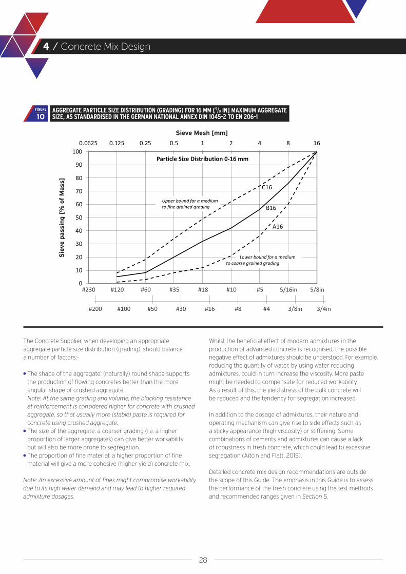
Selection and assessment of aggregate particle size distribution (grading) is an important element of concrete mix design, where grading is simply the division of an aggregate into fractions, each fraction consisting of one class of particle sizes. To minimise the risk or tendency for segregation, aggregates should be well graded (Dreux and Festa, 1998).
Figure 10 shows the typical range of aggregate particle size distributions for tremie concrete using maximum 16 mm [5/8 in] aggregate. It is recommended that the solid line is used as a starting point for the concrete mix design. Similar distributions for other maximum aggregate sizes are given in DIN 1045-2.
4.3
INFLUENCE OF CEMENT AND OTHER CONSTITUENTS ON RHEOLOGY (BASED ON WALLEVIK, 2003)09
FIGURE
28
4 / Concrete Mix Design
The Concrete Supplier, when developing an appropriate aggregate particle size distribution (grading), should balance a number of factors:-
● The shape of the aggregate: (naturally) round shape supports the production of flowing concretes better than the more angular shape of crushed aggregate. Note: At the same grading and volume, the blocking resistance at reinforcement is considered higher for concrete with crushed aggregate, so that usually more (stable) paste is required for concrete using crushed aggregate.
● The size of the aggregate: a coarser grading (i.e. a higher proportion of larger aggregates) can give better workability but will also be more prone to segregation.
● The proportion of fine material: a higher proportion of fine material will give a more cohesive (higher yield) concrete mix.
Note: An excessive amount of fines might compromise workability due to its high water demand and may lead to higher required admixture dosages.
Whilst the beneficial effect of modern admixtures in the production of advanced concrete is recognised, the possible negative effect of admixtures should be understood. For example, reducing the quantity of water, by using water reducing admixtures, could in turn increase the viscosity. More paste might be needed to compensate for reduced workability. As a result of this, the yield stress of the bulk concrete will be reduced and the tendency for segregation increased.
In addition to the dosage of admixtures, their nature and operating mechanism can give rise to side effects such as a sticky appearance (high viscosity) or stiffening. Some combinations of cements and admixtures can cause a lack of robustness in fresh concrete, which could lead to excessive segregation (Aitcin and Flatt, 2015).
Detailed concrete mix design recommendations are outside the scope of this Guide. The emphasis in this Guide is to assess the performance of the fresh concrete using the test methods and recommended ranges given in Section 5.
Sieve Mesh [mm]
Sie
ve p
assi
ng [
% o
f M
ass]
AGGREGATE PARTICLE SIZE DISTRIBUTION (GRADING) FOR 16 MM [5/8 IN] MAXIMUM AGGREGATE SIZE, AS STANDARDISED IN THE GERMAN NATIONAL ANNEX DIN 1045-2 TO EN 206-110
FIGURE
29
4 / Concrete Mix Design
Proportioning and Practical Considerations
Concrete mix limiting values should conform to European Standard EN 206 where the requirements of EN 1536 or EN 1538 have merged, or with the relevant local Standards or other standards specified for the project.
Due to new developments or specific work conditions deviation from these standards may be considered; such as partial replacement of cement e.g. by fly ash or even the use of a lower cement content than the limiting value. Three concepts are available for the use and application of Type II additions or approved procedures for acknowledgment of equivalent performance (as described in Appendix B). These are:-
1. The k-value concept.2. Equivalent concrete performance concept.3. The equivalent performance of combinations concept.
Following initial development in the laboratory (suitability testing) it is advisable to carry out full size production field trials (field batching trials) to assess performance and check the suitability of specified properties. Suitable time periods should be allowed in contract programs to carry out the required testing.
The field batch testing and evaluation should be carried out or supported by qualified personnel. Care should be taken to verify that the conditions that existed during field batching trials continue to exist during construction. If conditions change (aggregate source, cement source, type or dosage of additions, chemical admixture, etc.), new trial concrete mix studies should be conducted to ensure that the target properties and performance will continue to be achieved (FHWA GEC10).
The required dosage of admixture should be determined by field batch trials where the conditions (ambient temperature, delivery times, concrete pouring techniques, etc.) expected during construction are replicated, and a sample of concrete is retained and tested to determine its workability retention characteristics. This trial-mixture study should also include workability testing to develop a graph of workability loss versus time after batching.
It is essential to control the mixing time to ensure that no uncontrolled effect of admixtures originates before or during the actual placement. Laboratory and field trial testing should help to ensure that the optimum dosage of admixture and mixing time is used in order to minimise potential risks.
The effectiveness of some super plasticisers is dependent on temperature and it is therefore important to check the mix over the full range of temperatures anticipated during the progress of the works. Without adjusting the dosages of retarding admixtures, an increase in temperature of about 10 °C [18 °F] will increase the rate of slump loss by a factor of approximately 2, which means that a slump loss graph made in the laboratory at 22 °C [72 °F] will be very misleading for concrete being poured in the field at higher temperatures of 32 °C [90 °F] (Tuthill, 1960).
It is common practice to adopt summer and winter concrete mixes with different doses of admixtures and minor adjustments to the cement content and water/cement ratio.
Special attention should be paid to the type of concrete mixing procedure at the concrete batching plant. In the wet mixing process, the constituents are all mixed in a centralised concrete mixer at the batching plant and then transferred to concrete trucks for delivery. In the dry mixing process, the dry solid constituents are discharged into the concrete truck and then water added, with mixing taking place in the concrete truck.
In general, the wet mixing process is preferred over the dry mixing process for high performance concretes. It is however possible to supply high performance concrete using the dry mixing process but it is essential that the mixing time in the concrete truck is sufficient, especially during periods of high demand. It is recommended that detailed batch records with actual mixing time and quantities per truck load are obtained.
Testing of trial mixes in laboratory scale or, wherever possible, in full size batches should include an allowance for batching tolerances. Applicable test methods to characterise rheology including recommended ranges for acceptance are given in Section 5.
If the Concrete Supplier needs to have the ability to make minor adjustments to the agreed mix design to achieve the required properties, then the extent of such adjustments should be agreed in advance. In the absence of any such agreement, the agreed concrete mix design should not be amended or changed by the Concrete Supplier.
4.4
30
Specifying and Testing of Concrete, and Quality Control of Concrete Production
Section 5

31
5 / Specifying and Testing of Concrete, and Quality Control of Concrete Production
A New Approach to Specifying Fresh Concrete
It is critical that the rheological properties of the tremie concrete are specified for the reasons described in Section 3. These properties should be established through concrete mix design development and rigorous suitability trials and appropriate conformity and acceptance testing to ensure that these properties are maintained throughout a project.
Current standard practice is to specify compressive strength, minimum cement content, maximum water/cement ratio, and slump or flow-table test. These parameters are insufficient to fully describe the required fresh properties for tremie concrete, particularly in terms of workability, workability retention and stability.
Additional requirements for the concrete should be specified by the Specifier in terms of single target values, test methods and acceptance criteria as shown in Section 5.3.
Test Methods to Characterise Fresh Concrete
A detailed review by the Technical University of Munich and Missouri University of Science and Technology (Kraenkel and Gehlen, 2018) identified that the fundamental properties characterising concrete workability are yield stress and viscosity. As there are currently no practical field tests to measure these properties directly, indirect measurements are required. Both the slump flow and slump flow velocity tests described in Appendix A.1 can be used to give an indirect measurement of the relevant characteristics as well as giving an indication of stability using the VSI test. Figure 11 illustrates the correlation between yield and slump flow. Figure 12 shows the approximate correlation between viscosity and slump flow velocity.
In addition to the slump flow, slump flow velocity and VSI combined test (Appendix A.1), other tests to characterise the fresh concrete with regard to workability, workability retention and stability are given in Appendices A.2 to A.10. The relevance of these other tests is given in Section 5.3.
The slump test (Appendix A.2) and the flow table test (Appendix A.3) are standard tests to determine workability in accordance with EN 12350-2 and -5. Based on the R & D work that has been carried out, the slump flow test gives a better correlation to the yield stress for tremie concrete than the slump and flow table test. In this Guide, the slump flow is presented as the preferred parameter to represent yield stress.
The L-box test may give a good indication on the passing ability of tremie concrete but this is deemed to be covered by the mandatory limitation of its maximum coarse aggregate. Due to the flow resistance to passing through the bars in the L-Box this test cannot directly be correlated with the rheological properties for tremie concretes and is therefore not recommended (Kraenkel and Gehlen, 2018).
5.1
5.2
SLUMP FLOW CURVE RELATED TO YIELD STRESS AND RECOMMENDED RANGE FOR TREMIE CONCRETE (SEE APPENDIX A.1.1 AND FIGURE 6)
11FIGURE
SLUMP FLOW VELOCITY CURVE RELATED TO VISCOSITY SHOWING THE RECOMMENDED RANGE OF MEDIUM VISCOSITY FOR TREMIE CONCRETE (TEST SEE APPENDIX A.1.2)
12FIGURE
32
5 / Specifying and Testing of Concrete, and Quality Control of Concrete Production
Suitability, Conformity and Acceptance Testing
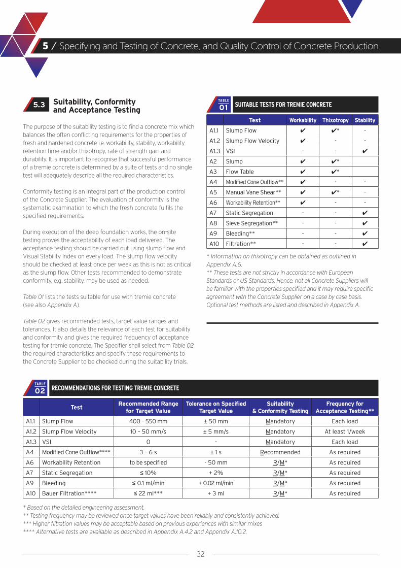
The purpose of the suitability testing is to find a concrete mix which balances the often conflicting requirements for the properties of fresh and hardened concrete i.e. workability, stability, workability retention time and/or thixotropy, rate of strength gain and durability. It is important to recognise that successful performance of a tremie concrete is determined by a suite of tests and no single test will adequately describe all the required characteristics.
Conformity testing is an integral part of the production control of the Concrete Supplier. The evaluation of conformity is the systematic examination to which the fresh concrete fulfils the specified requirements.
During execution of the deep foundation works, the on-site testing proves the acceptability of each load delivered. The acceptance testing should be carried out using slump flow and Visual Stability Index on every load. The slump flow velocity should be checked at least once per week as this is not as critical as the slump flow. Other tests recommended to demonstrate conformity, e.g. stability, may be used as needed.
Table 01 lists the tests suitable for use with tremie concrete (see also Appendix A).
Table 02 gives recommended tests, target value ranges and tolerances. It also details the relevance of each test for suitability and conformity and gives the required frequency of acceptance testing for tremie concrete. The Specifier shall select from Table 02 the required characteristics and specify these requirements to the Concrete Supplier to be checked during the suitability trials.
Test Workability Thixotropy Stability
A1.1 Slump Flow ✔ ✔* -
A1.2 Slump Flow Velocity ✔ - -
A1.3 VSI - - ✔
A2 Slump ✔ ✔*
A3 Flow Table ✔ ✔*
A4 Modified Cone Outflow** ✔ - -
A5 Manual Vane Shear** ✔ ✔* -
A6 Workability Retention** ✔ - -
A7 Static Segregation - - ✔
A8 Sieve Segregation** - - ✔
A9 Bleeding** - - ✔
A10 Filtration** - - ✔
* Information on thixotropy can be obtained as outlined in Appendix A.6.** These tests are not strictly in accordance with European Standards or US Standards. Hence, not all Concrete Suppliers will be familiar with the properties specified and it may require specific agreement with the Concrete Supplier on a case by case basis. Optional test methods are listed and described in Appendix A.
TestRecommended Range
for Target ValueTolerance on Specified
Target ValueSuitability
& Conformity TestingFrequency for
Acceptance Testing**
A1.1 Slump Flow 400 – 550 mm ± 50 mm Mandatory Each load
A1.2 Slump Flow Velocity 10 – 50 mm/s ± 5 mm/s Mandatory At least 1/week
A1.3 VSI 0 - Mandatory Each load
A4 Modified Cone Outflow**** 3 – 6 s ± 1 s Recommended As required
A6 Workability Retention to be specified - 50 mm R/M* As required
A7 Static Segregation ≤ 10% + 2% R/M* As required
A9 Bleeding ≤ 0.1 ml/min + 0.02 ml/min R/M* As required
A10 Bauer Filtration**** ≤ 22 ml*** + 3 ml R/M* As required
5.3 SUITABLE TESTS FOR TREMIE CONCRETE01TABLE
RECOMMENDATIONS FOR TESTING TREMIE CONCRETE02TABLE
* Based on the detailed engineering assessment.** Testing frequency may be reviewed once target values have been reliably and consistently achieved.*** Higher filtration values may be acceptable based on previous experiences with similar mixes**** Alternative tests are available as described in Appendix A.4.2 and Appendix A.10.2.
33
5 / Specifying and Testing of Concrete, and Quality Control of Concrete Production
Control of Workability Retention
It is important that the Specifier (see Figure 2) makes a realistic assessment of the period over which certain properties should be obtained, or the decrease of workability should be limited, especially for large pours (e.g. greater than 200 m3 [260 cy]), where supply capacity is limited, or where supply is complex due to a congested site. This assessment should include consideration of the following:-
● Period required to pour the pile/panel● Transport distance/time from plant to site● Concrete plant capacity and materials control● Availability of approved back-up facilities● Concrete truck capacity and number of trucks● Quality of site access● Climatic conditions, in particular temperature ● Actual loss of workability over time, see Tables 01 and 02
and Appendix A.6
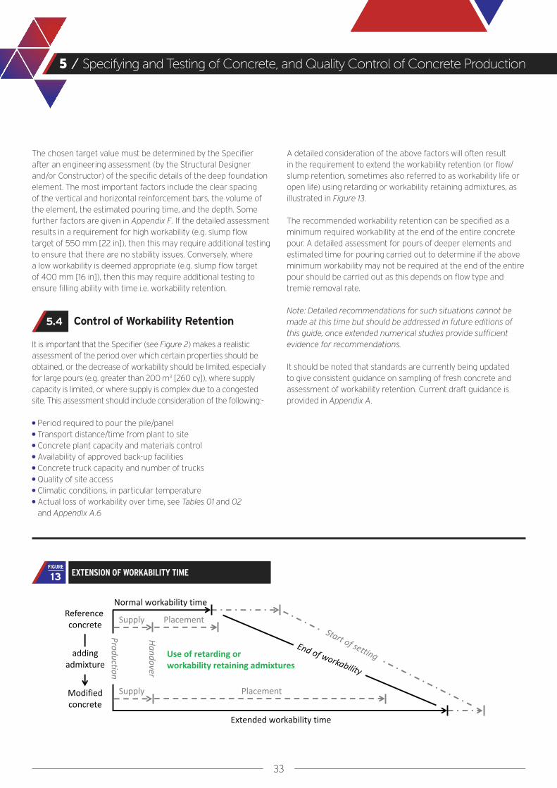
A detailed consideration of the above factors will often result in the requirement to extend the workability retention (or flow/slump retention, sometimes also referred to as workability life or open life) using retarding or workability retaining admixtures, as illustrated in Figure 13.
The recommended workability retention can be specified as a minimum required workability at the end of the entire concrete pour. A detailed assessment for pours of deeper elements and estimated time for pouring carried out to determine if the above minimum workability may not be required at the end of the entire pour should be carried out as this depends on flow type and tremie removal rate.
Note: Detailed recommendations for such situations cannot be made at this time but should be addressed in future editions of this guide, once extended numerical studies provide sufficient evidence for recommendations.
It should be noted that standards are currently being updated to give consistent guidance on sampling of fresh concrete and assessment of workability retention. Current draft guidance is provided in Appendix A.
5.4
EXTENSION OF WORKABILITY TIME 13FIGURE
The chosen target value must be determined by the Specifier after an engineering assessment (by the Structural Designer and/or Constructor) of the specific details of the deep foundation element. The most important factors include the clear spacing of the vertical and horizontal reinforcement bars, the volume of the element, the estimated pouring time, and the depth. Some further factors are given in Appendix F. If the detailed assessment results in a requirement for high workability (e.g. slump flow target of 550 mm [22 in]), then this may require additional testing to ensure that there are no stability issues. Conversely, where a low workability is deemed appropriate (e.g. slump flow target of 400 mm [16 in]), then this may require additional testing to ensure filling ability with time i.e. workability retention.

34
5 / Specifying and Testing of Concrete, and Quality Control of Concrete Production
Quality Control on the Concrete Manufacturing Process
Concrete Suppliers should work in accordance with the specified contract requirements (in Europe, EN 206 and its related National Annex). The Concrete Supplier should have product conformity certification with the following minimum requirements, wherever possible, though there are remote areas where it may be difficult to find suppliers with product conformity certification:-
● An approved quality management system ● Product testing by or calibrated against a laboratory
accredited for the tests undertaken● Surveillance that includes checking the validity of the producer’s
declarations of conformity, by a certification accreditation body
Note 1: Conformity control shall be in accordance with the conformity control requirements for designed concretes specified e.g. EN 206.
Note 2: Provisions for assessment, surveillance and certification of production control by an accredited body should be as specified in relevant standards e.g. EN 206.
The manufacturing process plays a key role in the consistency of the batched concrete and is therefore most important for the performance of tremie concrete. It is good practice to be familiar with the Supplier’s design, manufacturing and quality control process, prior to ordering concrete. The Concrete Supplier should inform the Specifier of the status of the concrete production plant at the time of tender and immediately if any change in status occurs during the period between the time of the order and the completion of supply.
In regions where Concrete Suppliers with the required level of product conformity certification are not available, it may be possible to use a Supplier with a lower level of quality assurance. It may then be the responsibility of the customer to ensure the correct quality and consistency (i.e. uniformity) of concrete supplied. As a minimum, suitably experienced personnel should check (or assess) the following items:- ● Calibration of weighting sensors to ensure
correct concrete mix proportions.● The free moisture content of the aggregates.
Note: Tremie concrete often contains a higher proportion of small aggregate than normal concretes and consequently the assumed free water content may be too low (Harrison, 2017)
● Calibration of flow meters where used for the addition of water etc. Note: Torque meters may be considered reliable for the intermediate ranges of workability.
● Method of measurement of admixtures.● Calibration of moisture probes both, automatic where used to
measure moisture contents in the fine aggregate, and hand held devices used to measure moisture content in the stock piles.
The following are considered good practice in order to supply tremie concrete with consistently suitable quality. Relevant requirements should be included in project specifications and include records for demonstration of conformity:-
● Moisture content of aggregates should be measured on a regular basis dependent on the volume of material being used, the weather conditions, the storage conditions, the sensitivity of the concrete mix etc. It should be noted that the moisture content of fine aggregate will vary more widely than that of coarse aggregate. It is common practice to adjust moisture content based on daily observation of coarse aggregate. Moisture content of fine aggregate will vary more widely and as a minimum should be checked for every load. However, modern batching plants normally have probes measuring moisture content of fine aggregate at the point of discharge to the concrete mixer (in-flight) and will adjust water demand accordingly. For major projects in-flight moisture probes should be specified.
Note 1: Monitoring of moisture content in the surface material of an aggregate bin that has not been recently disturbed may not be representative of the majority of the material in the bin.
Note 2: Surface moisture contents and absorption values for fine and coarse aggregates should be validated regularly by oven drying of representative samples.
Note 3: A consistent temperature and moisture content can be achieved by requiring aggregate to be conditioned for a minimum of 24 hours prior to batching.
● Control of the actual water content in fresh concrete should be made on a regular basis.
Note: Concrete is frequently batched using automatic controls that balance the volume of constituent added and the torque of the concrete mixer. For tremie concretes with high workability, these measurements may not be accurate enough and measurement of actual water content is preferred.
● Mixing water including any re-cycled water should be checked weekly for its fines content and chemical composition in order to ensure compliance with relevant standards e.g. US standard ASTM C1602 or EN 1008.
Note 1: The variation of re-cycled water may cause adverse effects on workability and therefore require additional admixtures to ensure the required workability is achieved. Workability retention should be retested if using recycled water. Note 2: Some contractors are reluctant to accept recycled water due to their experiences with greater scattering of fresh concrete properties, probably due to varying fines contents and/or varying remains from super-plasticisers.
5.5

35
5 / Specifying and Testing of Concrete, and Quality Control of Concrete Production
● Fine and coarse aggregate gradation of representative samples should be checked weekly or every time the supply source is changed.
● The concrete mixer should be thoroughly cleaned at least once a day.
● Electronic copies of weigh batch records should be printed directly for each concrete truck.
Note: All information needed by the user is on the delivery note and as there is a requirement for product conformity certification, the certification body as part of their routine practice will spot check that the batch records align with the specification (see Harrison, 2017 on interpreting batch records).
● The concrete truck mixers should be emptied of any residual concrete or water before being filled.
Note: It is the Specifier’s responsibility to allow or prohibit the use of recycled materials. The Concrete Supplier should be required to declare for approval any waste minimisation system. The use and control of recycled water, dust collection introduced to the concrete mixer or reclaimed aggregate should be identified and measured to control the content and the effect on the concrete.

36
Execution
Section 6
37
6 / Execution
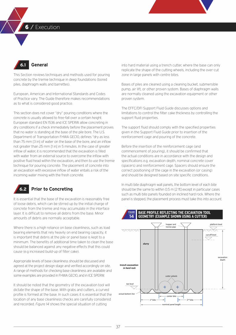
into hard material using a trench cutter, where the base can only replicate the shape of the cutting wheels, including the over-cut zone in large panels with centre bites.
Bases of piles are cleaned using a cleaning bucket, submersible pump, air lift, or other proven system. Bases of diaphragm walls are normally cleaned using the excavation equipment or other proven system.
The EFFC/DFI Support Fluid Guide discusses options and limitations to control the filter cake thickness by controlling the support fluid properties.
The support fluid should comply with the specified properties given in the Support Fluid Guide prior to insertion of the reinforcement cage and pouring of the concrete.
Before the insertion of the reinforcement cage (and commencement of pouring), it should be confirmed that the actual conditions are in accordance with the design and specifications e.g. excavation depth, nominal concrete cover (spacers) and reinforcement cage. Spacers should ensure the correct positioning of the cage in the excavation (or casing) and should be designed based on site specific conditions.
In multi bite diaphragm wall panels, the bottom level of each bite should be the same to within 0.5 m [2 ft] except in particular cases such as multi bite panels founded on inclined hard rock. Where the panel is stepped, the placement process must take this into account.
General
This Section reviews techniques and methods used for pouring concrete by the tremie technique in deep foundations (bored piles, diaphragm walls and barrettes).
European, American and International Standards and Codes of Practice vary. The Guide therefore makes recommendations as to what is considered good practice.
This section does not cover “dry” pouring conditions where the concrete is usually allowed to free-fall over a certain height. European standard EN 1536 and ICE SPERW allow concreting in dry conditions if a check immediately before the placement proves that no water is standing at the base of the pile bore. The U.S. Department of Transportation FHWA GEC10, defines “dry as less than 75 mm [3 in] of water on the base of the bore, and an inflow not greater than 25 mm [1 in] in 5 minutes. In the case of greater inflow of water, it is recommended that the excavation is filled with water from an external source to overcome the inflow with positive fluid head within the excavation, and then to use the tremie technique for pouring concrete. The placement of concrete into an excavation with excessive inflow of water entails a risk of the incoming water mixing with the fresh concrete.
Prior to Concreting
It is essential that the base of the excavation is reasonably free of loose debris, which can be stirred up by the initial charge of concrete from the tremie and may accumulate in the interface layer. It is difficult to remove all debris from the base. Minor amounts of debris are normally acceptable.
Where there is a high reliance on base cleanliness, such as load bearing elements that rely heavily on end bearing capacity, it is important that debris at the pile or panel base is kept to a minimum. The benefits of additional time taken to clean the base should be balanced against any negative effects that this could cause (e.g increased build-up of filter cake).
Appropriate levels of base cleanliness should be discussed and agreed at the project design stage and verified accordingly on site. A range of methods for checking base cleanliness are available and some examples are provided in FHWA GEC10, and in ICE SPERW.
It should be noted that the geometry of the excavation tool will dictate the shape of the base. With grabs and cutters, a curved profile is formed at the base. In such cases it is essential that the location of any base cleanliness checks are carefully considered and recorded. Figure 14 shows the special situation of cutting
6.1
6.2
BASE PROFILE REFLECTING THE EXCAVATION TOOL GEOMETRY (EXAMPLE SHOWN USING A CUTTER) 14
FIGURE
38
6 / Execution
The time elapsing between the final cleaning of the excavation and commencement of concreting should be kept as short as possible. Where elements such as stop-ends or reinforcement cages are to be inserted, cleaning should be carried out before insertion. The cleaning procedure, as well as the time between operations, should be established on the first panels. If delays occur, the support fluid quality should be rechecked and additional cleaning carried out if necessary.
Debris and particles which settle out of the support fluid will normally be carried on top of the rising concrete surface in the interface layer which is discussed in more detail in the EFFC/DFI Support Fluid Guide. The concrete is over-poured above the theoretical level to allow for later removal of the unsound concrete above cut-off level, resulting in sound concrete at cut-off level.
Tremie Equipment
Gravity tremie pipes should have a minimum internal diameter of 150 mm [6 in], or six times the maximum aggregate size, whichever is greater (EN 1536). A diameter of 250 mm [10 in] is commonly used. Pressurised tremie systems (pump lines) may be smaller than 150 mm [6 in].
Tremie pipes should be made from steel, as aluminium reacts with concrete.
Segmental pipes should be connected by a fully watertight structural connection. Typical sections have a length of 1 m to 5 m [3 ft to 15 ft]. Longer sections are generally preferred as this leads to fewer joints, but the order of the various lengths has to be considered according to the specific conditions (e.g. depth of excavation, hopper elevation, embedment at first pipe removal, and for the last loads at low hydrostatic pressure). In general, the pipes should be split at every joint each time they are used, and stored in a tremie frame, to allow proper cleaning. There have been examples of joints failing during tremie handling, so full visual checking is strongly recommended.
● Solid tremie pipes (without joints) may be used on shallow excavations where handling of the tremie permits.
● The hopper should have as large a volume as possible. The filling rate must allow for a continuous concrete supply to the tremie during the initial embedment of the tremie pipe.
● The pipes should be smooth clean and straight so that the frictional resistance to the concrete flow is minimised.
Tremie Spacing
Piles are normally circular and a single tremie pipe placed centrally within the bore is usually sufficient.
For diaphragm walls, codes specify various limits to the horizontal flow distance from 1.8 m to 2.5 m, [6 ft to 8 ft] with a maximum of 3 m [10 ft] (ICE SPERW, EN 1538, Z17). It is recommended that the distance is limited to 2 m [7 ft]. Longer travel distances of up to 3 m [10 ft] might be acceptable if the workability of the concrete is proven sufficient, in combination with clear spacing of reinforcement bars and concrete cover in excess of the minimum values. Full scale trials or numerical simulations (in particular by comparative studies) may assist in finding allowable values, see sections 7 and 9.
The tremie pipes should be positioned as symmetrically as possible in plan to avoid uneven rises in concrete level e.g. central for a single tremie pipe and approximately 1/4 of panel length from each end with 2 tremie pipes.
Initial Concrete Placement
Initiation of the concrete placement is one of the most critical steps in the entire placement process as the first load of concrete has to be separated from the support fluid.
Both wet and dry initial concrete pouring methods are described in various standards, guidelines and published technical papers (e.g. FHWA GEC10).
In the dry initial placement (often mistaken with “dry pour”) method, the end of the tremie pipe is closed and the concrete only gets into contact with the support fluid once it flows out of the tremie pipe. A steel or plywood plate with a sealing ring is placed on the bottom of the tremie pipe which enables fluid to be kept out of the pipe during lowering to the base of the excavation. The concrete is then discharged directly into the dry tremie pipe, and the pipe lifted by 0.1 m to 0.2 m [4 to 8 in] to allow the concrete to flow into the excavation. For deeper pours, it can be difficult to prevent fluid entering the tremie pipe through the segmental joints and/or prevent the tremie pipe from floating.
With the wet initial placement method, a separation medium must be used as the tremie pipe is full of fluid. Examples for such “plugs” include vermiculite granules (possibly bundled in a sack), inflatable rubber balls, sponges and foam balls and cylinders. A steel plate is sometimes additionally used at the base of the hopper when the hopper is filled and the plate then lifted using a crane. The plug must prevent the initial charge of concrete from mixing with the fluid which would lead to segregation in the tremie. To start concreting, the tremie pipe should be lowered to the bottom of the excavation and then raised a short distance
6.3
6.4
6.5

39
6 / Execution
Fluid level in excavationDiameter of tremie pipeDimension (diameter or thickness) of excavationDistance from bottom of excavation to tremie pipe outletConcrete level in excavationConcrete level in tremie pipe (= hydrostatic balance point) Embedment of tremie pipe before (1) / after (2) tremie pipe cutSection length of tremie pipe section to cut, with: h2 > 3 m [10ft]Hydrostatic pressure outside (o) / inside (i) of excavation Hydrostatic pressure inside the tremie pipe
hF
DT
Ddb-t
hc
hc,T h1/h 2
sT
po/pi
pi,T
Where:
(no greater than the diameter of the tremie pipe) to initiate concrete flow and allow the plug to exit from the base of the tremie. ICE SPERW states that a sliding plug of vermiculate should have a length of two times the tremie diameter and that the tremie should not be lifted more than 0.2 m [8 in] from the base. For practical reasons the wet initial placement method is the preferred method.
Figure 15 shows the pressure conditions before and during the stages of the pour and highlights that before the first cut the tremie pipe must be sufficiently embedded. However, due to dynamic aspects of concrete flow, the actual concrete level in the tremie pipe, in particular at the interruption after the initial pour, might be lower than the hydrostatic balance point as indicated in Figure 15.
The required concrete level should be assessed for each specific site condition but in most circumstances a minimum of 5 m [15 ft] (6 m [18 ft] according to EN 1536) is required before the first split of the tremie. It is essential that a sufficient volume of concrete, which is defined as the quantity to fill the minimum height, is available on site before the pour is commenced.
Tremie Embedment
The tremie requires a minimum embedment into the concrete that has already been poured. European execution standards (EN 1536, EN 1538) specify a minimum embedment of 1.5 m to 3 m [5 ft to 10 ft], with higher values for larger excavations. In general a minimum embedment of 3 m [10 ft] is well accepted in practice.
If temporary casing is being used during the tremie concrete pour, the removal of temporary casing sections should be considered with respect to maintaining minimum tremie embedment. Removal of temporary casing sections will cause the concrete level to drop as concrete fills the annulus left by the casing. Prior to removing a section of temporary casing, the tremie embedment depth should be adequate to maintain the minimum required embedment as the concrete level drops during casing removal.
When two or more tremie pipes are used (see Section 6.4) the tremie bases have to be kept at the same level (except where the base is stepped which requires special initial measures).
To get the concrete to flow, the weight of the concrete within the tremie pipe must overcome:-
● The resistance outside the base of the tremie pipe (hydrostatic fluid pressure)
● The resistance of the concrete already poured ● The friction between the concrete and the inside
face of the tremie pipe
Some authors refer to the ‘hydrostatic balance point’ where the gravity force within the tremie is in equilibrium with the resistance to flow (see Figure 15). Any concrete added above the hydrostatic balance point will cause the concrete to flow, and the higher the pouring rate the faster the flow out of the tremie outlet.
There are strong technical arguments to avoid excessive tremie embedment. Greater embedment leads to lower head pressure, loss of energy supply and slower concrete flow. Embedment ranging from 3 m [10 ft] minimum to 8 m [25 ft] maximum is recommended. At the end of the pour, i.e. close to the platform level, it is acceptable to reduce the minimum tremie embedment to 2 m [7 ft].
For small diameter bored piles the maximum embedment may need to be increased to avoid the need to split the tremie before an individual concrete truck load is fully discharged.
It is mandatory to measure the depth to the concrete at tremie positions after each load of concrete has been poured, which is often performed using a weighted tape. Where two (or more) tremie pipes are used in one panel it is essential to minimise the difference in concrete levels and discharge into both tremie pipes at the same time.
6.6
PHASES IN THE TREMIE POUR SEQUENCE15FIGURE
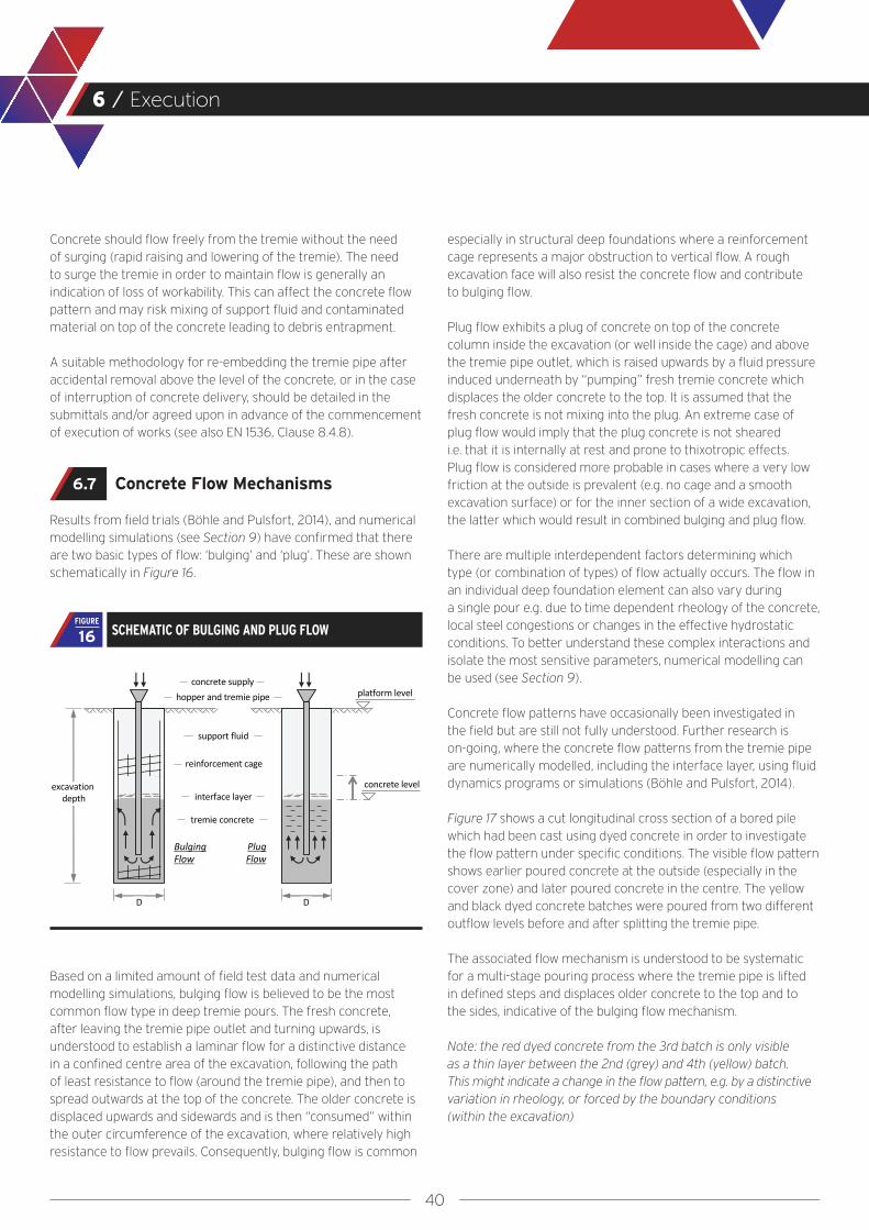
40
6 / Execution
Concrete should flow freely from the tremie without the need of surging (rapid raising and lowering of the tremie). The need to surge the tremie in order to maintain flow is generally an indication of loss of workability. This can affect the concrete flow pattern and may risk mixing of support fluid and contaminated material on top of the concrete leading to debris entrapment.
A suitable methodology for re-embedding the tremie pipe after accidental removal above the level of the concrete, or in the case of interruption of concrete delivery, should be detailed in the submittals and/or agreed upon in advance of the commencement of execution of works (see also EN 1536, Clause 8.4.8).
Concrete Flow Mechanisms
Results from field trials (Böhle and Pulsfort, 2014), and numerical modelling simulations (see Section 9) have confirmed that there are two basic types of flow: ‘bulging’ and ‘plug’. These are shown schematically in Figure 16.
Based on a limited amount of field test data and numerical modelling simulations, bulging flow is believed to be the most common flow type in deep tremie pours. The fresh concrete, after leaving the tremie pipe outlet and turning upwards, is understood to establish a laminar flow for a distinctive distance in a confined centre area of the excavation, following the path of least resistance to flow (around the tremie pipe), and then to spread outwards at the top of the concrete. The older concrete is displaced upwards and sidewards and is then “consumed” within the outer circumference of the excavation, where relatively high resistance to flow prevails. Consequently, bulging flow is common
especially in structural deep foundations where a reinforcement cage represents a major obstruction to vertical flow. A rough excavation face will also resist the concrete flow and contribute to bulging flow.
Plug flow exhibits a plug of concrete on top of the concrete column inside the excavation (or well inside the cage) and above the tremie pipe outlet, which is raised upwards by a fluid pressure induced underneath by “pumping” fresh tremie concrete which displaces the older concrete to the top. It is assumed that the fresh concrete is not mixing into the plug. An extreme case of plug flow would imply that the plug concrete is not sheared i.e. that it is internally at rest and prone to thixotropic effects. Plug flow is considered more probable in cases where a very low friction at the outside is prevalent (e.g. no cage and a smooth excavation surface) or for the inner section of a wide excavation, the latter which would result in combined bulging and plug flow.
There are multiple interdependent factors determining which type (or combination of types) of flow actually occurs. The flow in an individual deep foundation element can also vary during a single pour e.g. due to time dependent rheology of the concrete, local steel congestions or changes in the effective hydrostatic conditions. To better understand these complex interactions and isolate the most sensitive parameters, numerical modelling can be used (see Section 9).
Concrete flow patterns have occasionally been investigated in the field but are still not fully understood. Further research is on-going, where the concrete flow patterns from the tremie pipe are numerically modelled, including the interface layer, using fluid dynamics programs or simulations (Böhle and Pulsfort, 2014).
Figure 17 shows a cut longitudinal cross section of a bored pile which had been cast using dyed concrete in order to investigate the flow pattern under specific conditions. The visible flow pattern shows earlier poured concrete at the outside (especially in the cover zone) and later poured concrete in the centre. The yellow and black dyed concrete batches were poured from two different outflow levels before and after splitting the tremie pipe.
The associated flow mechanism is understood to be systematic for a multi-stage pouring process where the tremie pipe is lifted in defined steps and displaces older concrete to the top and to the sides, indicative of the bulging flow mechanism.
Note: the red dyed concrete from the 3rd batch is only visible as a thin layer between the 2nd (grey) and 4th (yellow) batch. This might indicate a change in the flow pattern, e.g. by a distinctive variation in rheology, or forced by the boundary conditions (within the excavation)
6.7
SCHEMATIC OF BULGING AND PLUG FLOW16FIGURE

41
6 / Execution
The dominant rheological property affecting the concrete flow pattern is the yield stress (indicated by the slump flow). The viscosity (indicated by the slump flow velocity) can have an effect on the overall time required for a pour (slower flow of concrete) and may affect the demand for workability retention, which should be reduced wherever possible. The viscosity also directly effects the resistance to flow of the (horizontal) concrete through windows in the reinforcement cage.
Where yield stress and viscosity increase with time, it may be necessary to adapt execution techniques during the pour e.g reducing the tremie embedment depth towards the end of the pour.
CROSS SECTION OF A BORED PILE CAST WITH DIFFERENTLY DYED LOADS OF TREMIE CONCRETE (BÖHLE AND PULSFORT, 2014), INDICATING BULGING FLOW 17
FIGURE

42
6 / Execution
Flow around Reinforcement and Box-Outs
As set out in Section 2, special consideration has to be given by the Structural Designer for any restriction to concrete flow. Any obstruction is a resistance to flow and will decrease the potential of the concrete used to properly flow around and embed a reinforcement bar or box-out. As the actual flow is a function of energy at the point of resistance, congestion is more critical at greater travel distances from the tremie pipe outlet and at higher elevations where the concrete head pressure is lower.
Detailing of the reinforcement cage, box-outs etc. has to comply with the codes (see Appendix E). In addition, Numerical modelling may be used to assess the sensitivity to changes in detailing and determine the least disruptive configurations.
Spacer blocks and other embedded items should be profiled to facilitate the flow of concrete.
Concreting Records
The depth of the concrete level at each tremie position and the embedded length of the tremie pipe recorded should be measured and recorded after the discharge of each load of concrete.
The depths measured, volumes poured, tremie lengths and casing lengths should be plotted immediately on a graph during the pouring operation and be compared with the theoretical values, considering the effects of excavation over-break. An example of such a graph is given in EN 1538 and in FHWA GEC10.
Such a comparison can help identify areas where over-break may have occurred or where concrete may be filling voids. Under-break is rare and under-consumption of concrete might indicate an issue such as instability, collapse, or mixing of support fluid, debris or soil with concrete. These measurements can identify an unusual condition in an excavation where more investigation may be warranted.
6.8
6.9

43
Full Scale Trials
Section 7
44
7 / Full Scale Trials
An effective way to obtain information on any deep foundation element is to install one or more full-scale test elements. These should ideally be constructed using the same installation technique, equipment and materials as proposed for the permanent works. Problems identified in full-scale trials can then be addressed before the permanent works are constructed. They also provide opportunities for refining aspects of the construction process and developing compliance parameters.
The extent and scope of the trial works should be proportionate to the project size, complexity and risks. The components to be tested should be selected from a review of:-
● The design and detailing● The fresh concrete performance● The Constructor’s placement methods,
overall experience and capability ● The experience in the given ground conditions This may require excavation to expose constructed elements to a significant depth.
In practice, such trials are best carried out by the appointed Constructor after mobilisation to site but prior to commencement of the permanent works. The time and cost of the trial must be recognised by the Client at an early stage, and specified in detail in the tender documents.
When budget and/or time schedule constraints do not allow for such full-scale trials, it is recommended to at least perform on-site concrete conformity testing in addition to the suitability testing typically performed in the supplier’s laboratory.

45
Quality Control of Completed Works
Section 8
46
8 / Quality Control of Completed Works
General
It is essential that the Constructor complies with relevant standards for quality assurance and control, and that the production process is supervised and undertaken by competent persons with suitable training, qualifications and experience.
Concrete placed in bored piles, diaphragm walls and barrettes is normally cast against the face of an open excavation and the placement process is not visible from the surface. Some imperfections of the hardened concrete of the deep foundation element are possible even though good practice construction methods were applied by the Constructor. Quality control requirements for the completed works should therefore make allowance for acceptance of some imperfections where these are not significant with regard to the structural performance and durability of the completed works. To support efficient and consistent inspection and acceptance, acceptable imperfections should be clearly identified in work procedures and inspection and test requirements.
Identification of acceptable imperfections may be based on past experience or through construction trials undertaken prior to the commencement of the main works. It is normally far better to spend time and effort on trials before the works commence, rather than specifying detailed and expensive quality control tests after completion. Another option is to expose and test a limited sample of piles or wall panels after the construction of the first elements and this can form part of the QA/QC procedures allowing any required corrective action(s) to be implemented at an early stage.
Post-Construction Testing Methods
A number of methods, both intrusive and non-intrusive are commonly available to provide some information regarding the geometry and the quality of the pile or wall.
An overview of methods is given in Appendix C.
Non-intrusive test methods are often difficult to interpret correctly and this requires specialist knowledge and experience.
Imperfections can generally fall into one of three categories:-
● Anomalous material● Channelling● Mattressing (may also be referred to as ‘shadowing’ or ‘quilting’)
A further description of each category of imperfection, together with examples, is given in Appendix D.
If imperfections become defects and if these are frequent, it can be possible to postulate an imperfection formation mechanism, which if detected early enough will enable changes to detailing, materials or processes to avoid further occurrences.
Imperfections can be caused by inappropriate detailing or by concrete that does not have appropriate flow properties or the adequate stability for the detailing and placement procedure in place, or by poor workmanship. Applying the recommendations of this Guide, especially by following the mutual approach of interaction between all parties involved, should help to minimise imperfections.
8.1 8.2

47
Numerical Modelling of Concrete Flow
Section 9

48
9 / Numerical Modelling of Concrete Flow
Introduction
Numerical modelling methods (e.g. using a Bingham Fluid Model) are extremely useful to understand the importance of individual factors affecting the flow of the concrete as well as assessing the sensitivity to changes in each factor, as set out in Table F.1.
By setting the rheological properties of the concrete and support fluid as well as defining the boundary conditions, it is possible to realistically model the bulk flow of the concrete inside an excavation.
Studies undertaken
The Task Group has worked with Academic Partners to determine fundamental interdependencies and corresponding sensitivities by reviewing model studies.
Figure 18 illustrates results from a 1.5 m [5 ft] diameter bored pile with a depth of 16 m [52 ft] and a reinforcement cage, with concrete pour simulating staged lifting of the tremie pipe. More simulations with numerical models from the Academic Partners are summarised in Li et al, 2018. Simulations demonstrate that bulk flow can be modelled successfully and single factors can be isolated to show their individual impact on flow mechanisms e.g that pouring much lower yield stress concrete into already poured (high yield stress) concrete can lead to irregular flow patterns.
1. 2. 3.
3rd level of tremie toe
2nd level of tremie toe
9.1
9.2
SIMULATIONS PRESENTING BULGING FLOW OF BULK CONCRETE BY VELOCITY STREAMLINES (LEFT), AND BY DYED CONCRETE FOLLOWING A STAGED LIFTING OF THE TREMIE PIPE (LI ET AL, 2018) 18
FIGURE

49
9 / Numerical Modelling of Concrete Flow
Figure 19 shows a simulation of a reinforced diaphragm wall panel with a variation in clear reinforcement spacing at different elevations, highlighting the risk for inclusions in the cover zone due to restrictions to flow (Li et al, 2018).
A review of the model studies has resulted in a number of important conclusions and these are discussed in Table F.1. Further details on Numerical Modelling Methods are given in the joint research paper by the Task Group and the Academic Partners (Li et al, 2018).
Limitations
Processing time for simulations is dependent on the degree of detail of the model itself and can extend, with present computer technology, up to a number of weeks for each individual numerical model simulation. Accurately defining the physical shape and size of the reinforcement cage greatly increases computation time. The option to replace the cage with a porous membrane gives good correlation but involves far less computation time (Roussel and Gram, 2014).
It is important to balance the complexity of the model with the envisaged sensitivity to the effect of change in parameters (based on experience from earlier simulations) in order to reduce the computation time and thereby allow more simulations to be carried out.
Numerical simulation is a powerful tool to solve the governing partial differential equations derived from the physical model. Hence the significance of numerical simulation is limited to the capacity of the underlying physical model (e.g. the Bingham fluid model).
Further work is ongoing using full scale trials and then validating the findings from a model against the actual trial.
9.3
SIMULATIONS PRESENTING FLOW OF BULK CONCRETE IN A QUARTER OF A DIAPHRAGM WALL PANEL, SHOWN FROM THE INSIDE (TO THE LEFT) AND FROM THE OUTSIDE OF A QUARTER PANEL, WITH INCLUSIONS DUE TO REBAR CONCENTRATIONS (IMAGES COURTESY OF JAN VAN DALEN)
19FIGURE
50
Test Methods to Characterise Fresh Concrete
Appendix A
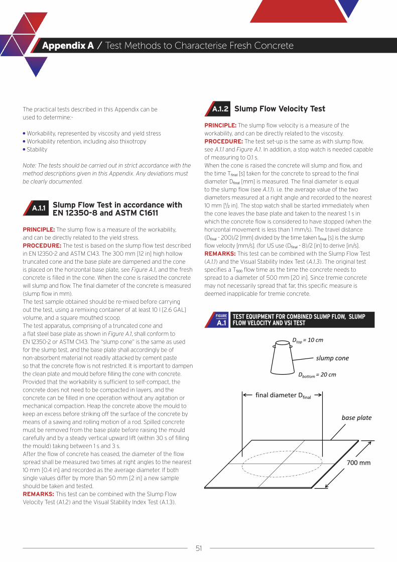
51
Appendix A / Test Methods to Characterise Fresh Concrete
The practical tests described in this Appendix can be used to determine:- ● Workability, represented by viscosity and yield stress ● Workability retention, including also thixotropy ● Stability
Note: The tests should be carried out in strict accordance with the method descriptions given in this Appendix. Any deviations must be clearly documented.
Slump Flow Test in accordance with EN 12350-8 and ASTM C1611
PRINCIPLE: The slump flow is a measure of the workability, and can be directly related to the yield stress.PROCEDURE: The test is based on the slump flow test described in EN 12350-2 and ASTM C143. The 300 mm [12 in] high hollow truncated cone and the base plate are dampened and the cone is placed on the horizontal base plate, see Figure A.1, and the fresh concrete is filled in the cone. When the cone is raised the concrete will slump and flow. The final diameter of the concrete is measured (slump flow in mm).The test sample obtained should be re-mixed before carrying out the test, using a remixing container of at least 10 l [2.6 GAL] volume, and a square mouthed scoop.The test apparatus, comprising of a truncated cone and a flat steel base plate as shown in Figure A.1, shall conform to EN 12350-2 or ASTM C143. The “slump cone” is the same as used for the slump test, and the base plate shall accordingly be of non-absorbent material not readily attacked by cement paste so that the concrete flow is not restricted. It is important to dampen the clean plate and mould before filling the cone with concrete.Provided that the workability is sufficient to self-compact, the concrete does not need to be compacted in layers, and the concrete can be filled in one operation without any agitation or mechanical compaction. Heap the concrete above the mould to keep an excess before striking off the surface of the concrete by means of a sawing and rolling motion of a rod. Spilled concrete must be removed from the base plate before raising the mould carefully and by a steady vertical upward lift (within 30 s of filling the mould) taking between 1 s and 3 s.After the flow of concrete has ceased, the diameter of the flow spread shall be measured two times at right angles to the nearest 10 mm [0.4 in] and recorded as the average diameter. If both single values differ by more than 50 mm [2 in] a new sample should be taken and tested.REMARKS: This test can be combined with the Slump Flow Velocity Test (A1.2) and the Visual Stability Index Test (A.1.3).
Slump Flow Velocity Test
PRINCIPLE: The slump flow velocity is a measure of the workability, and can be directly related to the viscosity.PROCEDURE: The test set-up is the same as with slump flow, see A.1.1 and Figure A.1. In addition, a stop watch is needed capable of measuring to 0.1 s.When the cone is raised the concrete will slump and flow, and the time Tfinal [s] taken for the concrete to spread to the final diameter Dfinal [mm] is measured. The final diameter is equal to the slump flow (see A.1.1). i.e. the average value of the two diameters measured at a right angle and recorded to the nearest 10 mm [1/2 in]. The stop watch shall be started immediately when the cone leaves the base plate and taken to the nearest 1 s in which the concrete flow is considered to have stopped (when the horizontal movement is less than 1 mm/s). The travel distance (Dfinal - 200)/2 [mm] divided by the time taken tfinal [s] is the slump flow velocity [mm/s]. (for US use (Dfinal - 8)/2 [in] to derive [in/s].REMARKS: This test can be combined with the Slump Flow Test (A.1.1) and the Visual Stability Index Test (A.1.3). The original test specifies a T500 flow time as the time the concrete needs to spread to a diameter of 500 mm [20 in]. Since tremie concrete may not necessarily spread that far, this specific measure is deemed inapplicable for tremie concrete.
A.1.2
A.1.1
TEST EQUIPMENT FOR COMBINED SLUMP FLOW, SLUMP FLOW VELOCITY AND VSI TESTA.1
FIGURE
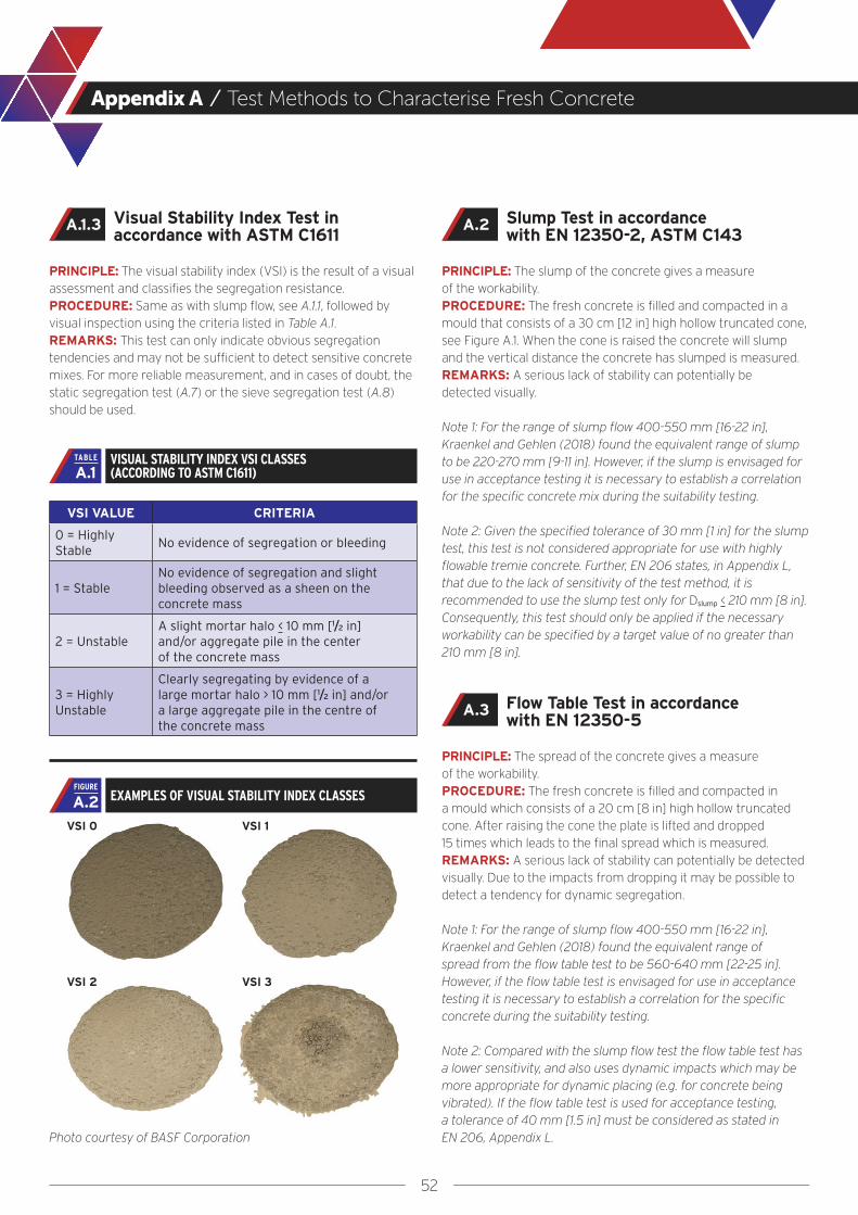
52
Appendix A / Test Methods to Characterise Fresh Concrete
Visual Stability Index Test in accordance with ASTM C1611
PRINCIPLE: The visual stability index (VSI) is the result of a visual assessment and classifies the segregation resistance. PROCEDURE: Same as with slump flow, see A.1.1, followed by visual inspection using the criteria listed in Table A.1.REMARKS: This test can only indicate obvious segregation tendencies and may not be sufficient to detect sensitive concrete mixes. For more reliable measurement, and in cases of doubt, the static segregation test (A.7) or the sieve segregation test (A.8) should be used.
VSI VALUE CRITERIA
0 = Highly Stable
No evidence of segregation or bleeding
1 = StableNo evidence of segregation and slight bleeding observed as a sheen on the concrete mass
2 = UnstableA slight mortar halo < 10 mm [1/2 in] and/or aggregate pile in the center of the concrete mass
3 = Highly Unstable
Clearly segregating by evidence of a large mortar halo > 10 mm [1/2 in] and/or a large aggregate pile in the centre of the concrete mass
VSI 0
Photo courtesy of BASF Corporation
VSI 1
VSI 2 VSI 3
Slump Test in accordance with EN 12350-2, ASTM C143
PRINCIPLE: The slump of the concrete gives a measure of the workability.PROCEDURE: The fresh concrete is filled and compacted in a mould that consists of a 30 cm [12 in] high hollow truncated cone, see Figure A.1. When the cone is raised the concrete will slump and the vertical distance the concrete has slumped is measured.REMARKS: A serious lack of stability can potentially be detected visually.
Note 1: For the range of slump flow 400-550 mm [16-22 in], Kraenkel and Gehlen (2018) found the equivalent range of slump to be 220-270 mm [9-11 in]. However, if the slump is envisaged for use in acceptance testing it is necessary to establish a correlation for the specific concrete mix during the suitability testing.
Note 2: Given the specified tolerance of 30 mm [1 in] for the slump test, this test is not considered appropriate for use with highly flowable tremie concrete. Further, EN 206 states, in Appendix L, that due to the lack of sensitivity of the test method, it is recommended to use the slump test only for Dslump < 210 mm [8 in]. Consequently, this test should only be applied if the necessary workability can be specified by a target value of no greater than 210 mm [8 in].
Flow Table Test in accordance with EN 12350-5
PRINCIPLE: The spread of the concrete gives a measure of the workability.PROCEDURE: The fresh concrete is filled and compacted in a mould which consists of a 20 cm [8 in] high hollow truncated cone. After raising the cone the plate is lifted and dropped 15 times which leads to the final spread which is measured. REMARKS: A serious lack of stability can potentially be detected visually. Due to the impacts from dropping it may be possible to detect a tendency for dynamic segregation.
Note 1: For the range of slump flow 400-550 mm [16-22 in], Kraenkel and Gehlen (2018) found the equivalent range of spread from the flow table test to be 560-640 mm [22-25 in]. However, if the flow table test is envisaged for use in acceptance testing it is necessary to establish a correlation for the specific concrete during the suitability testing.
Note 2: Compared with the slump flow test the flow table test has a lower sensitivity, and also uses dynamic impacts which may be more appropriate for dynamic placing (e.g. for concrete being vibrated). If the flow table test is used for acceptance testing, a tolerance of 40 mm [1.5 in] must be considered as stated in EN 206, Appendix L.
A.2A.1.3
A.3
VISUAL STABILITY INDEX VSI CLASSES (ACCORDING TO ASTM C1611)A.1
TABLE
EXAMPLES OF VISUAL STABILITY INDEX CLASSESA.2FIGURE

53
Appendix A / Test Methods to Characterise Fresh Concrete
Modified Cone Outflow Test
PRINCIPLE: The outflow time of the concrete from the modified cone is a measure of the workability, and can be directly related to the viscosity.PROCEDURE: A hollow cylinder is mounted on top of an inverted, hollow truncated cone, with a flap at its bottom opening, which is closed before commencement of testing, see Figure A.3. 20 litres [5 GAL] of fresh concrete is filled in the form with an excess above the top. The surface is struck off using a rod or scraping ruler. The filling operation should be performed within 1 min. Within another 1 min, the flap is quickly opened and the out-flow time of the free-falling concrete is recorded until the cone is empty. Time is recorded to an accuracy of 0.1 s.REMARKS: To contain 20 litres [5 GAL] (19.9 l by calculation) of fresh concrete in total, the height of the cylinder shall be 465 mm [18 in] with a constant inner diameter of 200 mm [7.8 in] (containing 14.6 l [3.8 GAL], and adding to the volume of the cone containing 5.3 l [1.4 GAL]). The truncated cone can be the standard cone as used for the slump test. An alternative test method to determine the outflow time is the inverted cone outflow test, see A.4.2.
A.4.1
EQUIPMENT (EXAMPLE) FOR THE MODIFIED CONE OUTFLOW TEST A.3
FIGURE
Outflow TestA.4 Inverted Cone Outflow Test
PRINCIPLE: The outflow time of the concrete from the inverted cone is a measure of the workability, and can be related to the viscosity.PROCEDURE: Using the same equipment as for the slump flow test according to A.1, plus a stop watch, the form is placed upside down (inverted) on the flat steel base plate, with the 100 mm wide opening at the bottom. The concrete is filled into the cone in one operation and compacted 25 times with a rod. After striking off the surface and waiting for 30 s the cone is lifted vertically by approximately 40 cm [12 to 16 in] within 2 to 4 seconds. The outflow time of the concrete is recorded until the cone is empty. Time is recorded to the nearest 0.1 s. REMARKS: If this test is envisaged to be used for conformity or acceptance testing, a target value should be determined and agreed within the suitability testing. Due to the smaller volume of the concrete, in comparison to the modified cone outflow test (A.4.1), and due to a possible influence of the lifting operation the inverted cone outflow time may be less accurate than the modified cone outflow test, in particular for lower viscosities. It has however been shown to give reliable information for tremie concrete mixes to detect low, medium or high viscosity. Without detailed specification, a minimum of 2 seconds and a maximum of 7 seconds might apply as the recommended range for acceptance testing.
A.4.2
Images courtesy of Thomas Kraenkel
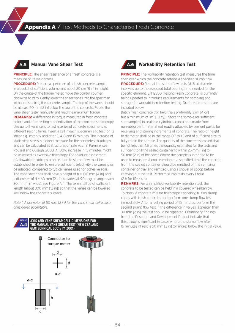
54
Appendix A / Test Methods to Characterise Fresh Concrete
Workability Retention Test
PRINCIPLE: The workability retention test measures the time span over which the concrete retains a specified slump flow. PROCEDURE: Repeat the slump flow tests (A1.1) at discrete intervals up to the assessed total pouring time needed for the specific element. EN 12350 (Testing Fresh Concrete) is currently being updated to introduce requirements for sampling and storage for workability retention testing. Draft requirements are included below.Batch fresh concrete (for field trials preferably 3 m3 [4 cy] but a minimum of 1m3 [1.3 cy]). Store the sample (or sufficient sub-samples) in sealable cylindrical containers made from non-absorbent material not readily attacked by cement paste, for receiving and storing increments of concrete. The ratio of height to diameter shall be in the range 0.7 to 1.3 and of sufficient size to fully retain the sample. The quantity of the concrete sampled shall be not less than 1.5 times the quantity estimated for the tests and sufficient to fill the sealed container to within 25 mm [1 in] to 50 mm [2 in] of the cover. Where the sample is intended to be used to measure slump retention at a specified time, the concrete from the sealed container should be emptied on the remixing container or tray and remixed using a shovel or scoop before carrying out the test. Perform slump tests every 1 hour (2 h for life > 4 h)REMARKS: For a simplified workability retention test, the concrete to be tested can be held in a covered wheelbarrow.To check a concrete mix for thixotropic tendency, fill two slump cones with fresh concrete, and perform one slump flow test immediately. After a resting period of 15 minutes, perform the second slump flow test. If the difference in values is greater than 30 mm [2 in] the test should be repeated. Preliminary findings from the Research and Development Project indicate that thixotropy is significant in cases where the slump flow after 15 minutes of rest is 50 mm [2 in] (or more) below the initial value.
A.6
AXIS AND VANE SHEAR CELL DIMENSIONS FOR THE MANUAL VANE SHEAR TEST (NEW ZEALAND GEOTECHNICAL SOCIETY, 2001)
A.4FIGURE
Manual Vane Shear Test
PRINCIPLE: The shear resistance of a fresh concrete is a measure of its yield stress.PROCEDURE: Prepare a specimen of a fresh concrete sample in a bucket of sufficient volume and about 20 cm [8 in] in height. On the gauge of the torque meter, move the pointer counter-clockwise to zero. Gently lower the shear vanes into the specimen without disturbing the concrete sample. The top of the vanes should be at least 50 mm [2 in] below the top of the concrete. Rotate the vane shear tester manually and read the maximum torque. REMARKS: A difference in torque measured in fresh concrete before and after resting is an indication of the concrete’s thixotropy. Use up to 5 vane cells to test a series of concrete specimens at different resting times. Insert a cell in each specimen and test for its shear e.g. instantly and after 2, 4, 8 and 15 minutes. The increase of static yield stress is a direct measure for the concrete’s thixotropy and can be calculated as structuration rate Athix (in Pa/min), see Roussel and Cussigh, 2008. A 100% increase in 15 minutes might be assessed as excessive thixotropy. For absolute assessment of allowable thixotropy a correlation to slump flow must be established. In order to ensure sufficient selectivity the vanes shall be adapted, compared to typical vanes used for cohesive soils. The vane shear cell shall have a height of h = 100 mm [4 in] and a diameter of d = 60 mm [2 in] (4 blades at 90 degree angle each 30 mm [1 in] wide), see Figure A.4. The axle shall be of sufficient length (about 300 mm [12 in]) so that the vanes can be lowered well below the concrete surface. Note 1: A diameter of 50 mm [2 in] for the vane shear cell is also considered acceptable.
A.5
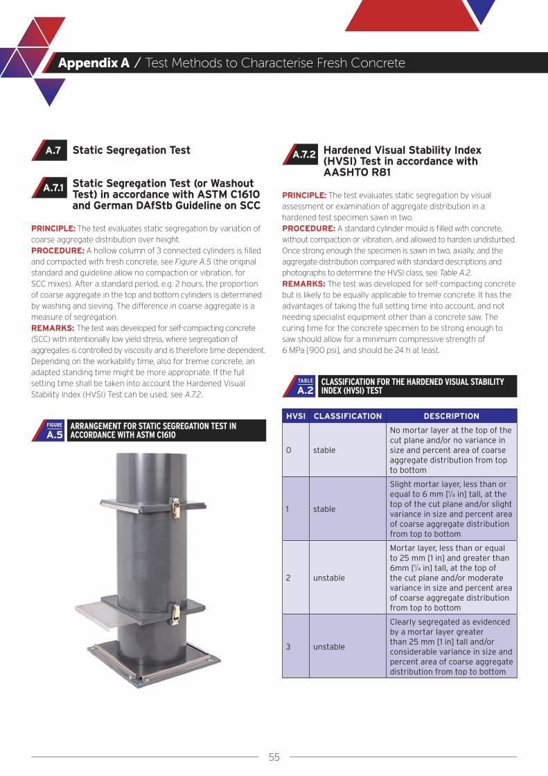
55
Appendix A / Test Methods to Characterise Fresh Concrete
Hardened Visual Stability Index (HVSI) Test in accordance with AASHTO R81
PRINCIPLE: The test evaluates static segregation by visual assessment or examination of aggregate distribution in a hardened test specimen sawn in two.PROCEDURE: A standard cylinder mould is filled with concrete, without compaction or vibration, and allowed to harden undisturbed. Once strong enough the specimen is sawn in two, axially, and the aggregate distribution compared with standard descriptions and photographs to determine the HVSI class, see Table A.2.REMARKS: The test was developed for self-compacting concrete but is likely to be equally applicable to tremie concrete. It has the advantages of taking the full setting time into account, and not needing specialist equipment other than a concrete saw. The curing time for the concrete specimen to be strong enough to saw should allow for a minimum compressive strength of 6 MPa [900 psi], and should be 24 h at least.
HVSI CLASSIFICATION DESCRIPTION
0 stable
No mortar layer at the top of the cut plane and/or no variance in size and percent area of coarse aggregate distribution from top to bottom
1 stable
Slight mortar layer, less than or equal to 6 mm [1/4 in] tall, at the top of the cut plane and/or slight variance in size and percent area of coarse aggregate distribution from top to bottom
2 unstable
Mortar layer, less than or equal to 25 mm [1 in] and greater than 6mm [1/4 in] tall, at the top of the cut plane and/or moderate variance in size and percent area of coarse aggregate distribution from top to bottom
3 unstable
Clearly segregated as evidenced by a mortar layer greater than 25 mm [1 in] tall and/or considerable variance in size and percent area of coarse aggregate distribution from top to bottom
A.7.2
CLASSIFICATION FOR THE HARDENED VISUAL STABILITY INDEX (HVSI) TESTA.2
TABLE
Static Segregation Test
Static Segregation Test (or Washout Test) in accordance with ASTM C1610 and German DAfStb Guideline on SCC
PRINCIPLE: The test evaluates static segregation by variation of coarse aggregate distribution over height.PROCEDURE: A hollow column of 3 connected cylinders is filled and compacted with fresh concrete, see Figure A.5 (the original standard and guideline allow no compaction or vibration, for SCC mixes). After a standard period, e.g. 2 hours, the proportion of coarse aggregate in the top and bottom cylinders is determined by washing and sieving. The difference in coarse aggregate is a measure of segregation.REMARKS: The test was developed for self-compacting concrete (SCC) with intentionally low yield stress, where segregation of aggregates is controlled by viscosity and is therefore time dependent. Depending on the workability time, also for tremie concrete, an adapted standing time might be more appropriate. If the full setting time shall be taken into account the Hardened Visual Stability Index (HVSI) Test can be used, see A.7.2.
A.7
ARRANGEMENT FOR STATIC SEGREGATION TEST IN ACCORDANCE WITH ASTM C1610 A.5
FIGURE
A.7.1
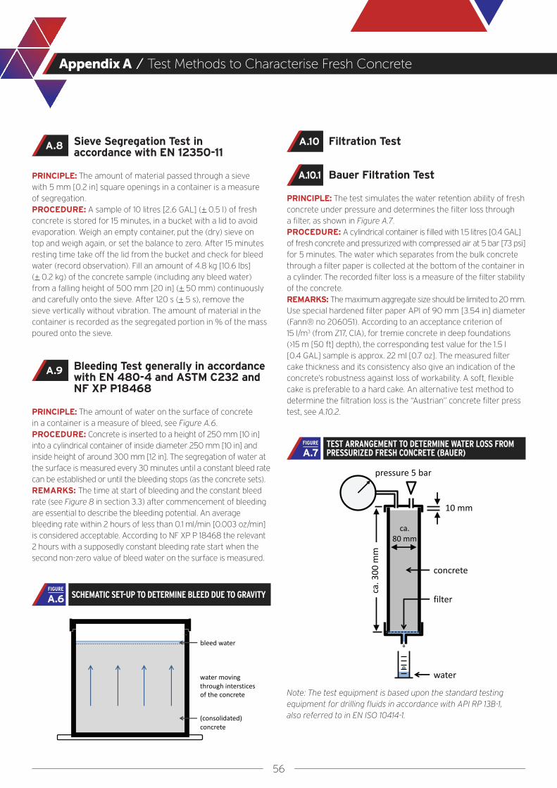
56
Appendix A / Test Methods to Characterise Fresh Concrete
Filtration Test
Bauer Filtration Test
PRINCIPLE: The test simulates the water retention ability of fresh concrete under pressure and determines the filter loss through a filter, as shown in Figure A.7.PROCEDURE: A cylindrical container is filled with 1.5 litres [0.4 GAL] of fresh concrete and pressurized with compressed air at 5 bar [73 psi] for 5 minutes. The water which separates from the bulk concrete through a filter paper is collected at the bottom of the container in a cylinder. The recorded filter loss is a measure of the filter stability of the concrete. REMARKS: The maximum aggregate size should be limited to 20 mm.Use special hardened filter paper API of 90 mm [3.54 in] diameter (Fann® no 206051). According to an acceptance criterion of 15 l/m3 (from Z17, CIA), for tremie concrete in deep foundations (>15 m [50 ft] depth), the corresponding test value for the 1.5 l [0.4 GAL] sample is approx. 22 ml [0.7 oz]. The measured filter cake thickness and its consistency also give an indication of the concrete’s robustness against loss of workability. A soft, flexible cake is preferable to a hard cake. An alternative test method to determine the filtration loss is the “Austrian” concrete filter press test, see A.10.2.
Note: The test equipment is based upon the standard testing equipment for drilling fluids in accordance with API RP 13B-1, also referred to in EN ISO 10414-1.
A.10
A.10.1
TEST ARRANGEMENT TO DETERMINE WATER LOSS FROM PRESSURIZED FRESH CONCRETE (BAUER) A.7
FIGURE
Sieve Segregation Test in accordance with EN 12350-11
PRINCIPLE: The amount of material passed through a sieve with 5 mm [0.2 in] square openings in a container is a measure of segregation.PROCEDURE: A sample of 10 litres [2.6 GAL] (+ 0.5 l) of fresh concrete is stored for 15 minutes, in a bucket with a lid to avoid evaporation. Weigh an empty container, put the (dry) sieve on top and weigh again, or set the balance to zero. After 15 minutes resting time take off the lid from the bucket and check for bleed water (record observation). Fill an amount of 4.8 kg [10.6 lbs] (+ 0.2 kg) of the concrete sample (including any bleed water) from a falling height of 500 mm [20 in] (+ 50 mm) continuously and carefully onto the sieve. After 120 s (+ 5 s), remove the sieve vertically without vibration. The amount of material in the container is recorded as the segregated portion in % of the mass poured onto the sieve.
Bleeding Test generally in accordance with EN 480-4 and ASTM C232 and NF XP P18468
PRINCIPLE: The amount of water on the surface of concrete in a container is a measure of bleed, see Figure A.6.PROCEDURE: Concrete is inserted to a height of 250 mm [10 in] into a cylindrical container of inside diameter 250 mm [10 in] and inside height of around 300 mm [12 in]. The segregation of water at the surface is measured every 30 minutes until a constant bleed rate can be established or until the bleeding stops (as the concrete sets).REMARKS: The time at start of bleeding and the constant bleed rate (see Figure 8 in section 3.3) after commencement of bleeding are essential to describe the bleeding potential. An average bleeding rate within 2 hours of less than 0.1 ml/min [0.003 oz/min] is considered acceptable. According to NF XP P 18468 the relevant 2 hours with a supposedly constant bleeding rate start when the second non-zero value of bleed water on the surface is measured.
A.8
A.9
SCHEMATIC SET-UP TO DETERMINE BLEED DUE TO GRAVITY A.6FIGURE
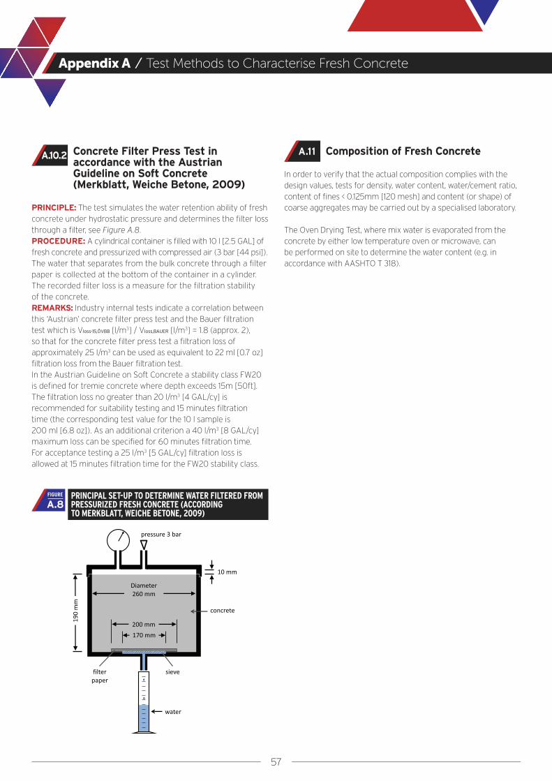
57
Appendix A / Test Methods to Characterise Fresh Concrete
Composition of Fresh Concrete
In order to verify that the actual composition complies with the design values, tests for density, water content, water/cement ratio, content of fines < 0.125mm [120 mesh] and content (or shape) of coarse aggregates may be carried out by a specialised laboratory.
The Oven Drying Test, where mix water is evaporated from the concrete by either low temperature oven or microwave, can be performed on site to determine the water content (e.g. in accordance with AASHTO T 318).
Concrete Filter Press Test in accordance with the Austrian Guideline on Soft Concrete (Merkblatt, Weiche Betone, 2009)
PRINCIPLE: The test simulates the water retention ability of fresh concrete under hydrostatic pressure and determines the filter loss through a filter, see Figure A.8.PROCEDURE: A cylindrical container is filled with 10 l [2.5 GAL] of fresh concrete and pressurized with compressed air (3 bar [44 psi]). The water that separates from the bulk concrete through a filter paper is collected at the bottom of the container in a cylinder. The recorded filter loss is a measure for the filtration stability of the concrete. REMARKS: Industry internal tests indicate a correlation between this ‘Austrian’ concrete filter press test and the Bauer filtration test which is Vloss-15,ÖVBB [l/m3] / Vloss,BAUER [l/m3] = 1.8 (approx. 2), so that for the concrete filter press test a filtration loss of approximately 25 l/m3 can be used as equivalent to 22 ml [0.7 oz] filtration loss from the Bauer filtration test.In the Austrian Guideline on Soft Concrete a stability class FW20 is defined for tremie concrete where depth exceeds 15m [50ft]. The filtration loss no greater than 20 l/m3 [4 GAL/cy] is recommended for suitability testing and 15 minutes filtration time (the corresponding test value for the 10 l sample is 200 ml [6.8 oz]). As an additional criterion a 40 l/m3 [8 GAL/cy] maximum loss can be specified for 60 minutes filtration time. For acceptance testing a 25 l/m3 [5 GAL/cy] filtration loss is allowed at 15 minutes filtration time for the FW20 stability class.
A.10.2
PRINCIPAL SET-UP TO DETERMINE WATER FILTERED FROM PRESSURIZED FRESH CONCRETE (ACCORDING TO MERKBLATT, WEICHE BETONE, 2009)
A.8FIGURE
A.11

58
Concepts for Use of Additions
Appendix B

59
Appendix B / Concepts for Use of Additions
Specified minimum cement contents for concrete in deep foundations are often not necessary to obtain the required strength class, but to obtain specific fresh properties. Additions like fly ash and GGBS are often used to replace part of the cement, which in turn affects the fresh concrete’s workability, flow retention and stability, as well as strength, durability and overall sustainability.
Three concepts are available for the use and application of (reactive) Type II additions (EN 206):-
1. The k-value concept, 2. The Equivalent Concrete Performance Concept (ECPC) and 3. The Equivalent Performance of Combinations Concept (EPCC).
The rules for the application of the three concepts vary within the different CEN member states. For each project, the concept should be carefully considered, both from a technical and an economical point of view.
K-Value Concept
The k-value concept is a prescriptive concept. It is based on the comparison of the durability performance of a reference concrete with another one in which part of the cement is replaced by an addition as a function of the water/cement ratio and the addition content.
The k-value concept permits type II additions to be taken into account:-
● By replacing the term “water/cement ratio” with “water/(cement + k * addition) ratio” and;
● The amount of (cement + k * addition) shall not be less than the minimum cement content required for the relevant exposure class.
The rules of application of the k-value concept for fly ash conforming to European standard EN 450-1, silica fume conforming to EN 13263-1, and ground granulated blast furnace slag conforming to EN 15167-1 together with cements of type CEM I and CEM II/A conforming to EN 197-1 are given in corresponding clauses in EN 206.
Modifications to the rules of the k-value concept may be applied where their suitability has been established (e.g. higher k-values, increased proportions of additions, use of other additions, combinations of additions and other cements).
For a further description of the full procedure and application of the k-value concept, the reader is referred to CEN/TR 16639.
Equivalent Concrete Performance Concept (ECPC)
The principles of the Equivalent Concrete Performance Concept have been introduced in EN 206.
This concept permits amendments to the requirements for minimum cement content and maximum water/cement ratio when a combination of a specific addition and a specific cement source is used where the manufacturing source and characteristics of each are clearly defined. It shall be proven that the concrete has an equivalent performance especially with respect to its interaction with the environment and to its durability when compared with a reference concrete in accordance with the requirements for the relevant exposure class.
The reference cement shall fulfil the requirements of EN 197-1 and originates from a source that has been used in practice in the place of use within the last five years and used in the selected exposure class. The reference concrete shall conform to the provisions valid in the place of use for the selected exposure class.
The constituents for designed and prescribed concrete shall be chosen to satisfy the requirements specified for fresh and hardened concrete, including consistence, density, strength, durability, and protection of embedded steel against corrosion, taking into account the production process and the intended method of execution of concrete works.
Equivalent Performance of Combinations Concept (EPCC)
The principles of the ”Equivalent Performance of Combinations Concept” permit a defined range of combinations of cement conforming to European standard EN 197-1 and addition (or additions) having established suitability that may count fully towards requirements for maximum water/cement ratio and minimum cement content which are specified for a concrete.
The elements of the methodology are:-
1. Identify a cement type that conforms to a European cement standard and that has the same or similar composition to the intended combination
2. Assess whether the concretes produced with the combination have similar strength and durability as concretes made with the identified cement type for the relevant exposure class
3. Apply production control that ensures these requirements for the concretes containing the combination are defined and implemented.
In Europe there are three methods applied to establish the equivalent performance of combinations -the UK method, the Irish method and the Portuguese method. These three methods have been developed separately and differ considerably in the requirements for the control of the combinations. The three methods are fully described in CEN/TR 16639.

60
Methods for Testing Completed Works
Appendix C
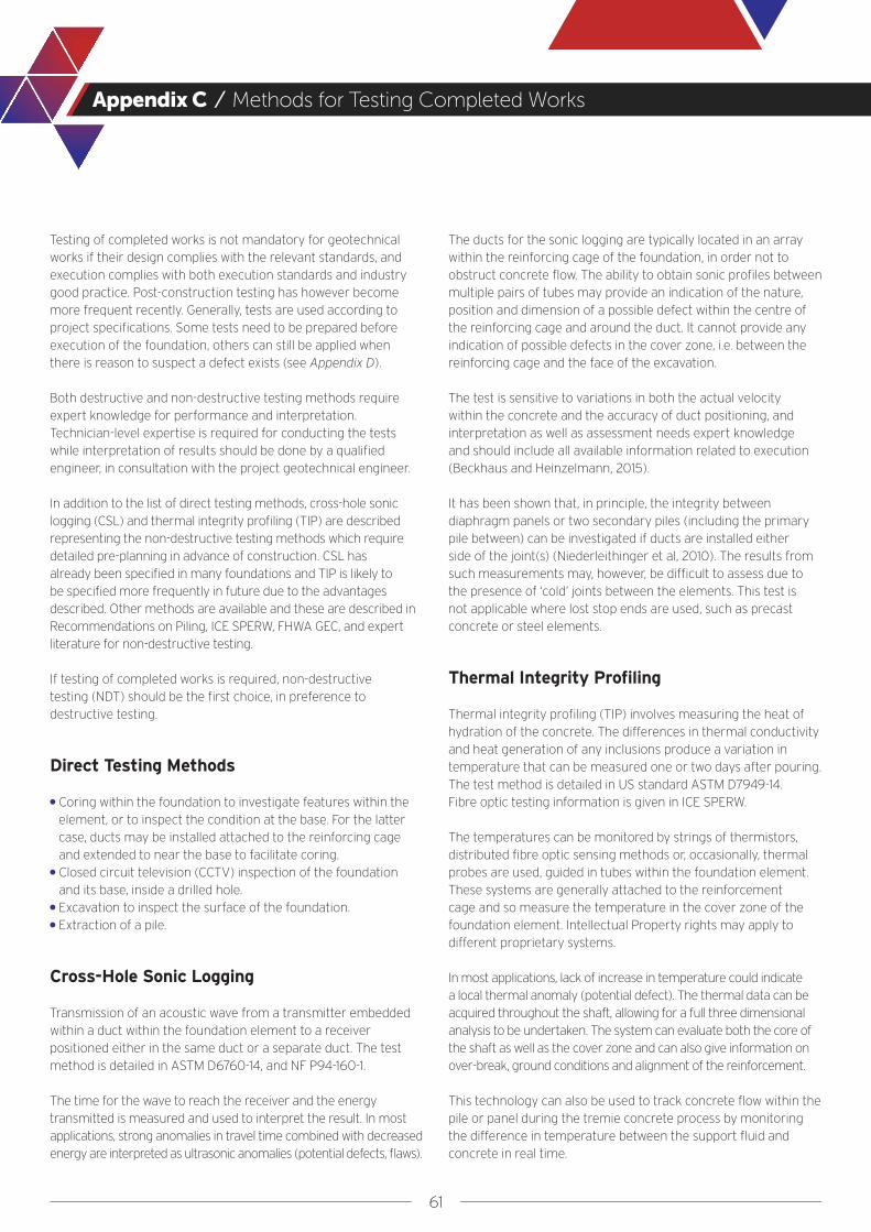
61
Appendix C / Methods for Testing Completed Works
Testing of completed works is not mandatory for geotechnical works if their design complies with the relevant standards, and execution complies with both execution standards and industry good practice. Post-construction testing has however become more frequent recently. Generally, tests are used according to project specifications. Some tests need to be prepared before execution of the foundation, others can still be applied when there is reason to suspect a defect exists (see Appendix D).
Both destructive and non-destructive testing methods require expert knowledge for performance and interpretation. Technician-level expertise is required for conducting the tests while interpretation of results should be done by a qualified engineer, in consultation with the project geotechnical engineer.
In addition to the list of direct testing methods, cross-hole sonic logging (CSL) and thermal integrity profiling (TIP) are described representing the non-destructive testing methods which require detailed pre-planning in advance of construction. CSL has already been specified in many foundations and TIP is likely to be specified more frequently in future due to the advantages described. Other methods are available and these are described in Recommendations on Piling, ICE SPERW, FHWA GEC, and expert literature for non-destructive testing.
If testing of completed works is required, non-destructive testing (NDT) should be the first choice, in preference to destructive testing.
Direct Testing Methods
● Coring within the foundation to investigate features within the element, or to inspect the condition at the base. For the latter case, ducts may be installed attached to the reinforcing cage and extended to near the base to facilitate coring.
● Closed circuit television (CCTV) inspection of the foundation and its base, inside a drilled hole.
● Excavation to inspect the surface of the foundation.● Extraction of a pile.
Cross-Hole Sonic Logging
Transmission of an acoustic wave from a transmitter embedded within a duct within the foundation element to a receiver positioned either in the same duct or a separate duct. The test method is detailed in ASTM D6760-14, and NF P94-160-1.
The time for the wave to reach the receiver and the energy transmitted is measured and used to interpret the result. In most applications, strong anomalies in travel time combined with decreased energy are interpreted as ultrasonic anomalies (potential defects, flaws).
The ducts for the sonic logging are typically located in an array within the reinforcing cage of the foundation, in order not to obstruct concrete flow. The ability to obtain sonic profiles between multiple pairs of tubes may provide an indication of the nature, position and dimension of a possible defect within the centre of the reinforcing cage and around the duct. It cannot provide any indication of possible defects in the cover zone, i.e. between the reinforcing cage and the face of the excavation.
The test is sensitive to variations in both the actual velocity within the concrete and the accuracy of duct positioning, and interpretation as well as assessment needs expert knowledge and should include all available information related to execution (Beckhaus and Heinzelmann, 2015).
It has been shown that, in principle, the integrity between diaphragm panels or two secondary piles (including the primary pile between) can be investigated if ducts are installed either side of the joint(s) (Niederleithinger et al, 2010). The results from such measurements may, however, be difficult to assess due to the presence of ‘cold’ joints between the elements. This test is not applicable where lost stop ends are used, such as precast concrete or steel elements.
Thermal Integrity Profiling
Thermal integrity profiling (TIP) involves measuring the heat of hydration of the concrete. The differences in thermal conductivity and heat generation of any inclusions produce a variation in temperature that can be measured one or two days after pouring. The test method is detailed in US standard ASTM D7949-14. Fibre optic testing information is given in ICE SPERW.
The temperatures can be monitored by strings of thermistors, distributed fibre optic sensing methods or, occasionally, thermal probes are used, guided in tubes within the foundation element. These systems are generally attached to the reinforcement cage and so measure the temperature in the cover zone of the foundation element. Intellectual Property rights may apply to different proprietary systems.
In most applications, lack of increase in temperature could indicate a local thermal anomaly (potential defect). The thermal data can be acquired throughout the shaft, allowing for a full three dimensional analysis to be undertaken. The system can evaluate both the core of the shaft as well as the cover zone and can also give information on over-break, ground conditions and alignment of the reinforcement.
This technology can also be used to track concrete flow within the pile or panel during the tremie concrete process by monitoring the difference in temperature between the support fluid and concrete in real time.
62
Interpretation of Imperfections
Appendix D
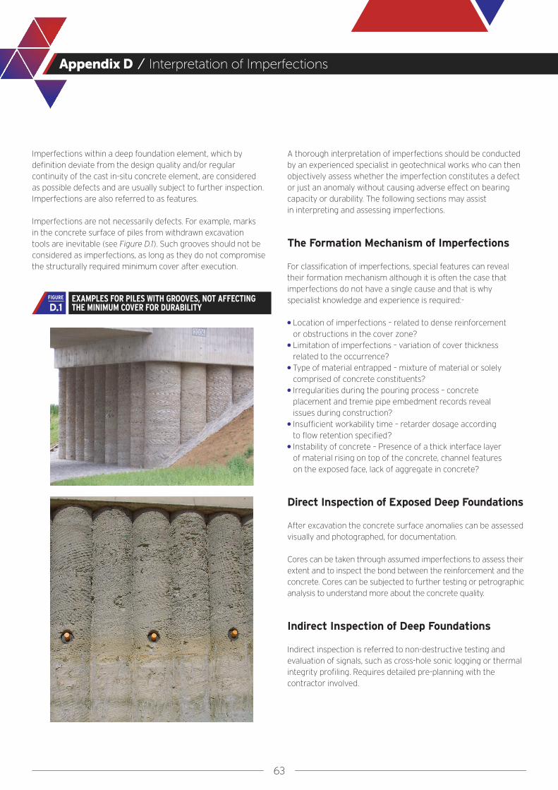
63
Appendix D / Interpretation of Imperfections
Imperfections within a deep foundation element, which by definition deviate from the design quality and/or regular continuity of the cast in-situ concrete element, are considered as possible defects and are usually subject to further inspection. Imperfections are also referred to as features.
Imperfections are not necessarily defects. For example, marks in the concrete surface of piles from withdrawn excavation tools are inevitable (see Figure D.1). Such grooves should not be considered as imperfections, as long as they do not compromise the structurally required minimum cover after execution.
A thorough interpretation of imperfections should be conducted by an experienced specialist in geotechnical works who can then objectively assess whether the imperfection constitutes a defect or just an anomaly without causing adverse effect on bearing capacity or durability. The following sections may assist in interpreting and assessing imperfections.
The Formation Mechanism of Imperfections
For classification of imperfections, special features can reveal their formation mechanism although it is often the case that imperfections do not have a single cause and that is why specialist knowledge and experience is required:-
● Location of imperfections – related to dense reinforcement or obstructions in the cover zone?
● Limitation of imperfections – variation of cover thickness related to the occurrence?
● Type of material entrapped – mixture of material or solely comprised of concrete constituents?
● Irregularities during the pouring process – concrete placement and tremie pipe embedment records reveal issues during construction?
● Insufficient workability time – retarder dosage according to flow retention specified?
● Instability of concrete – Presence of a thick interface layer of material rising on top of the concrete, channel features on the exposed face, lack of aggregate in concrete?
Direct Inspection of Exposed Deep Foundations
After excavation the concrete surface anomalies can be assessed visually and photographed, for documentation.
Cores can be taken through assumed imperfections to assess their extent and to inspect the bond between the reinforcement and the concrete. Cores can be subjected to further testing or petrographic analysis to understand more about the concrete quality.
Indirect Inspection of Deep Foundations
Indirect inspection is referred to non-destructive testing and evaluation of signals, such as cross-hole sonic logging or thermal integrity profiling. Requires detailed pre-planning with the contractor involved.
EXAMPLES FOR PILES WITH GROOVES, NOT AFFECTING THE MINIMUM COVER FOR DURABILITYD.1
FIGURE

64
Appendix D / Interpretation of Imperfections
Classification of Type of Imperfections
Once imperfections are interpreted as systematic, they should be classified. Most imperfections will fall into one of the following three categories:-
Inclusions
Inclusions consist of entrapped material within the foundation that does not conform to the reference concrete. It can be uncemented material originating from a mixture of the support fluid, excavated material and the concrete, such as from the interface layer, or poorly cemented material originated from segregated concrete. Two examples are shown in Figure D.2.
Inclusions are usually considered acceptable if limited in their extent and frequency. Only if these are of such dimensions that they are affecting the bearing capacity, or occupy wide parts in the cover zone and can therefore reduce durability, should inclusions be classified as defects. An irregular flow pattern such as illustrated in Figure D.3 where the “fresh, fluid concrete” is not able to displace the “old, stiff concrete” (over a large area of the cross-section as shown in Figure 16 and Figure 17) may cause such inclusions.
Non-destructive testing can assist in identifying inclusions (see Appendix C). These tests need special knowledge and experience with which the imperfection’s extent might be assessed by further evaluations.
Channelling
Channelling is also referred to as bleed channels. These are vertical narrow zones with lightly cemented aggregate with a lack of fines and cement matrix, usually near the surface of the panel or pile. This phenomenon is due to an insufficient stability of the concrete (poor segregation/bleeding resistance) for the actual ground and placement conditions.
Bleed channels are usually not considered defects if they are isolated and of limited thickness, thus not reducing the durability significantly (see Figure D.3). In addition, bleed water can pass up around vertical installations within the cross-sections e.g. vertical reinforcement bars, or within the core of wide elements.
EXAMPLES OF INCLUSIONS IN A DIAPHRAGM WALL AND A PILE (PILE PHOTO TAKEN FROM FIGURE 9.14B, FHWA GEC10) D.2
FIGURE
SCHEMATIC OF A CONCRETE VENT DUE TO LOSS IN CONCRETE MIX WORKABILITY DURING TREMIE PLACEMENT (ACCORDING TO FIGURE 9.13, FHWA GEC10), WHERE AN INTERFACE LAYER CAN PARTLY BE ENTRAPPED BY CONCRETE AND FORM AN INCLUSION
D.3FIGURE
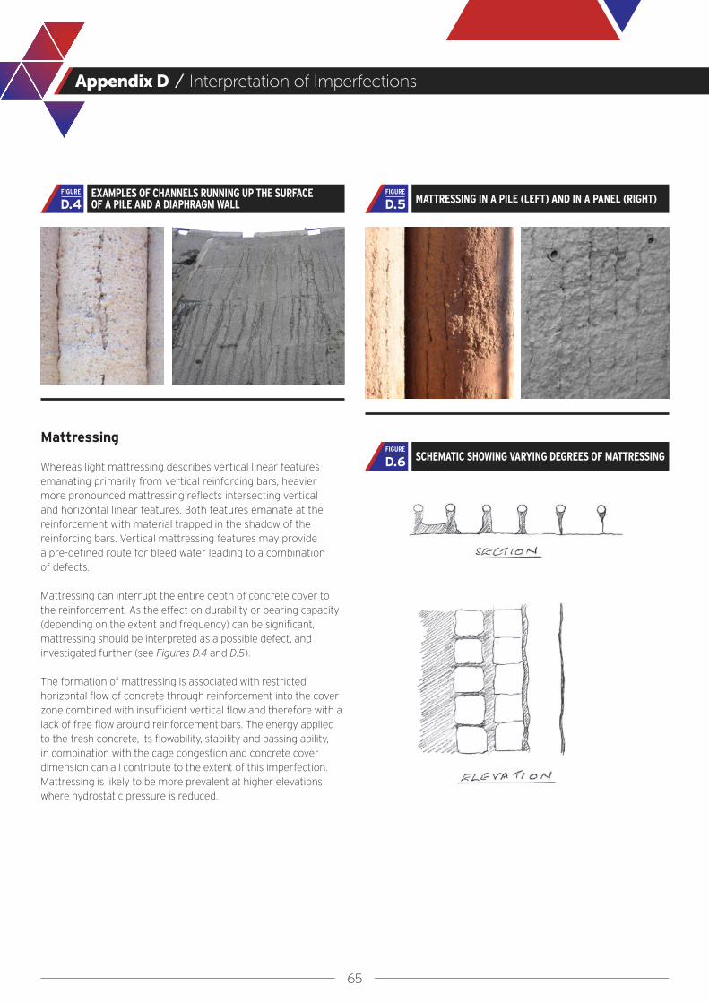
65
Appendix D / Interpretation of Imperfections
Mattressing
Whereas light mattressing describes vertical linear features emanating primarily from vertical reinforcing bars, heavier more pronounced mattressing reflects intersecting vertical and horizontal linear features. Both features emanate at the reinforcement with material trapped in the shadow of the reinforcing bars. Vertical mattressing features may provide a pre-defined route for bleed water leading to a combination of defects.
Mattressing can interrupt the entire depth of concrete cover to the reinforcement. As the effect on durability or bearing capacity (depending on the extent and frequency) can be significant, mattressing should be interpreted as a possible defect, and investigated further (see Figures D.4 and D.5).
The formation of mattressing is associated with restricted horizontal flow of concrete through reinforcement into the cover zone combined with insufficient vertical flow and therefore with a lack of free flow around reinforcement bars. The energy applied to the fresh concrete, its flowability, stability and passing ability, in combination with the cage congestion and concrete cover dimension can all contribute to the extent of this imperfection. Mattressing is likely to be more prevalent at higher elevations where hydrostatic pressure is reduced.
EXAMPLES OF CHANNELS RUNNING UP THE SURFACE OF A PILE AND A DIAPHRAGM WALL D.4
FIGUREMATTRESSING IN A PILE (LEFT) AND IN A PANEL (RIGHT) D.5
FIGURE
SCHEMATIC SHOWING VARYING DEGREES OF MATTRESSING D.6FIGURE

66
Appendix E
Detailed Information on Design Considerations
67
Appendix E / Detailed Information on Design Considerations
This Appendix should be read in conjunction with Section 2 and includes supplementary information on detailing, concrete cover, single columns on single piles, all related to the impact on concrete flow.
Detailing
The detailing of deep foundation structures should only be carried out by experienced personnel.
Every effort must be made to ensure that reinforcement is not congested and satisfies the minimum clear spacing rules as given in relevant standards. Where a high density of reinforcement is required the maximum available bar diameter and maximum bar spacing should be used. Where multiple layers are needed special focus must be given to the maintenance of sufficient concrete flow (see sections 3 and 6). It is often the case that very dense reinforcement indicates that the dimensions of the deep foundation element need to be increased.
Additional constraints on reinforcing cage layout also include:-
● Additional reinforcement to allow lifting and placing (e.g. stirrups and cross-bracings)
● Space for the stop end (where used)● Space for the tremie pipe● Instrumentation● Width and length constraints due to transportation restrictions● The weight of the reinforcement cage● Items in the cover zone such as spacers, box outs or couplers● Tie-back sleeves and other embedded items such as utility
blockouts, etc.
Detailing requirements for cages are summarized in Tables E.1, E.2 and E.3.
Structural codes like EN 1992 set general normative regulations for the detailing, in particular for the spacing and the concrete cover of structural elements. These are also valid for deep foundations i.e. for their structural design. Execution tolerances, such as the dimensions of the reinforcement cage, are considered, but these cannot cover all the specific tolerances for deep foundations. Subsequently, execution standards like EN 1536 and EN 1538 set additional regulations, leading sometimes to conflicting interpretations.
Reinforcement Clear Spacing
The clear spacing between reinforcement bars affects the ability of concrete to flow into the cover zone, and must be appropriate for the actual conditions. This is difficult to quantify as it requires consideration of the spacing between horizontal and vertical bars, clear window size, the layout of multiple rows of reinforcement, the concrete aggregate size, and the rheology in connection with flow distances and hydrostatic pressures. Transverse reinforcement which runs through the centre of the reinforcing cage, (couplers, links, tie rods etc.) affects the vertical upward flow of the concrete.
There is consensus that spacing of reinforcement bars for deep foundations shall be much higher than required by the structural codes, due to the onerous execution requirements.
As set out in Section 2.2, a minimum clear spacing on vertical of 100 mm [4 in] should be mandatory. FHWA GEC10 recommends values from 5 to 10 times the maximum aggregate size for difficult installation conditions i.e. very large or very deep elements, multiple bar layers and intricate cage geometry. This also includes splice zones or where bars are connected with couplers.
It is hoped that future research by computational simulations, validated by field trials, may assist in establishing better rules for the appropriate clear spacing.
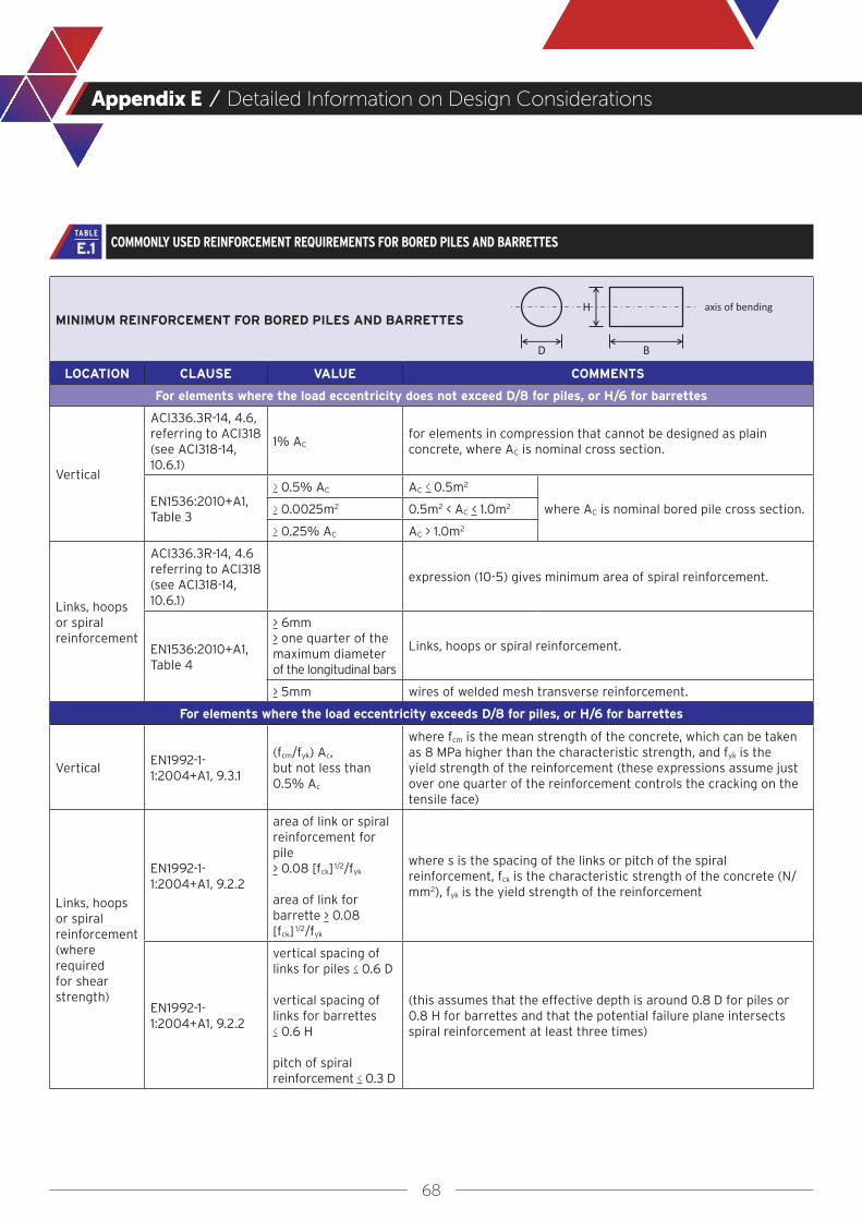
68
Appendix E / Detailed Information on Design Considerations
MINIMUM REINFORCEMENT FOR BORED PILES AND BARRETTES
LOCATION CLAUSE VALUE COMMENTS
For elements where the load eccentricity does not exceed D/8 for piles, or H/6 for barrettes
Vertical
ACI336.3R-14, 4.6, referring to ACI318 (see ACI318-14, 10.6.1)
1% ACfor elements in compression that cannot be designed as plain concrete, where AC is nominal cross section.
EN1536:2010+A1, Table 3
> 0.5% AC AC < 0.5m2
where AC is nominal bored pile cross section.> 0.0025m2 0.5m2 < AC < 1.0m2
> 0.25% AC AC > 1.0m2
Links, hoops or spiral reinforcement
ACI336.3R-14, 4.6 referring to ACI318(see ACI318-14, 10.6.1)
expression (10-5) gives minimum area of spiral reinforcement.
EN1536:2010+A1, Table 4
> 6mm> one quarter of the maximum diameter of the longitudinal bars
Links, hoops or spiral reinforcement.
> 5mm wires of welded mesh transverse reinforcement.
For elements where the load eccentricity exceeds D/8 for piles, or H/6 for barrettes
VerticalEN1992-1-1:2004+A1, 9.3.1
(fcm/fyk) Ac,but not less than 0.5% Ac
where fcm is the mean strength of the concrete, which can be taken as 8 MPa higher than the characteristic strength, and fyk is the yield strength of the reinforcement (these expressions assume just over one quarter of the reinforcement controls the cracking on the tensile face)
Links, hoops or spiral reinforcement (where required for shear strength)
EN1992-1-1:2004+A1, 9.2.2
area of link or spiral reinforcement for pile > 0.08 [fck] 1/2/fyk
area of link for barrette > 0.08 [fck] 1/2/fyk
where s is the spacing of the links or pitch of the spiral reinforcement, fck is the characteristic strength of the concrete (N/mm2), fyk is the yield strength of the reinforcement
EN1992-1-1:2004+A1, 9.2.2
vertical spacing of links for piles < 0.6 D
vertical spacing of links for barrettes < 0.6 H
pitch of spiral reinforcement < 0.3 D
(this assumes that the effective depth is around 0.8 D for piles or 0.8 H for barrettes and that the potential failure plane intersects spiral reinforcement at least three times)
COMMONLY USED REINFORCEMENT REQUIREMENTS FOR BORED PILES AND BARRETTESE.1TABLE
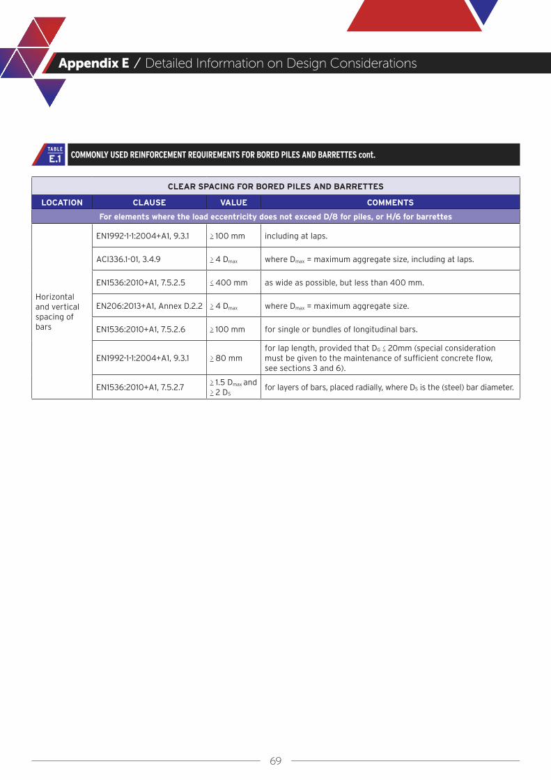
69
Appendix E / Detailed Information on Design Considerations
CLEAR SPACING FOR BORED PILES AND BARRETTES
LOCATION CLAUSE VALUE COMMENTS
For elements where the load eccentricity does not exceed D/8 for piles, or H/6 for barrettes
Horizontal and vertical spacing of bars
EN1992-1-1:2004+A1, 9.3.1 > 100 mm including at laps.
ACI336.1-01, 3.4.9 > 4 Dmax where Dmax = maximum aggregate size, including at laps.
EN1536:2010+A1, 7.5.2.5 < 400 mm as wide as possible, but less than 400 mm.
EN206:2013+A1, Annex D.2.2 > 4 Dmax where Dmax = maximum aggregate size.
EN1536:2010+A1, 7.5.2.6 > 100 mm for single or bundles of longitudinal bars.
EN1992-1-1:2004+A1, 9.3.1 > 80 mmfor lap length, provided that DG < 20mm (special consideration must be given to the maintenance of sufficient concrete flow, see sections 3 and 6).
EN1536:2010+A1, 7.5.2.7> 1.5 Dmax and> 2 DS
for layers of bars, placed radially, where DS is the (steel) bar diameter.
COMMONLY USED REINFORCEMENT REQUIREMENTS FOR BORED PILES AND BARRETTES cont.E.1TABLE

70
Appendix E / Detailed Information on Design Considerations
MINIMUM REINFORCEMENT FOR DIAPHRAGM WALLS
LOCATION CLAUSE VALUE COMMENTS
For elements where the load eccentricity does not exceed D/8 for piles, or H/6 for barrettes
Vertical - for walls where the load eccentricity does not exceed H/6
EN1992-1-1:2004+A1, 9.6.2
0.2% AC where AC is nominal area of panel
EN1538:2010+A1, 7.5.3.1
DS > 12 mm where DS is the (steel) bar diameter
EN1538:2010+A1, 7.5.3.1
> 3 bars / m on each side of the reinforcement cage
Vertical - for walls where the load eccentricity exceeds H/6
EN1992-1-1:2004+A1, 9.3.1
minimum area in each face / unit length = 0.26 (fcm/fyk) d, but not less than 0.0013 d
where fcm is the mean strength of the concrete, which can be taken as 8 N/mm2 higher than the characteristic strength, fyk is the yield strength of the reinforcement, and d is the effective depth to the centroid of the tension reinforcement from the compression face
EN1538:2010+A1, 7.5.3.1
DS > 12 mm where DS = (steel) bar diameter
EN1538:2010+A1, 7.5.3.1
> 3 bars / m on each side of the reinforcement cage
Horizontal
EN1992-1-1:2004+A1, 9.6.3
minimum total area / unit height > 0.1% AC
where AC is nominal area of vertical section through panel / unit height
EN1992-1-1:2004+A1, 9.6.3
minimum area in each face / unit height > 25% Asv
where Asv is the area of vertical reinforcement in face / unit length
EN1538:2010+A1 no specific requirements
Through-thickness links (where required for shear strength)
EN1992-1-1:2004+A1, 9.2.2
minimum area / unit area of wall (in elevation) (0.08 [fck]1/2)/fyk
where fck is the characteristic strength of the concrete, fyk is the yield strength of the reinforcement
EN1992-1-1:2004+A1, 9.2.2
horizontal spacing < 0.75 d, but not more than 600 mm where d is the effective depth to the centroid of the tension
reinforcement from the compression faceEN1992-1-1:2004+A1, 9.2.2
vertical spacing < 0.75 d
COMMONLY USED REINFORCEMENT REQUIREMENTS FOR DIAPHRAGM WALLSE.2TABLE

71
Appendix E / Detailed Information on Design Considerations
CLEAR SPACING FOR BORED PILES AND BARRETTES
LOCATION CLAUSE VALUE COMMENTS
For elements where the load eccentricity does not exceed D/8 for piles, or H/6 for barrettes
spacing of vertical bars
EN206:2013+A1, Annex D.2.2 > 4 Dmax where Dmax is the maximum aggregate size.
EN1538:2010+A1, 7.5.3.2 > 100 mm of single bars or groups, parallel to the wall face.
EN1538:2010+A1, 7.5.3.3 > 80 mmfor the lap length, provided that Dmax < 20mm (special consideration must be given to the maintenance of sufficient concrete flow, see sections 3 and 6).
vertical spacing of horizontal bars
EN1538:2010+A1, 7.5.4.2 > 200 mm
EN1538:2010+A1, 7.5.4.3 > 150 mmwhere required, provided that Dmax < 20mm, where Dmax is the maximum aggregate size.
horizontal spacing of transverse bars
EN1538:2010+A1, 7.5.4.4 > 150 mm
EN1538:2010+A1, 7.5.4.5 > 200 mm recommended
horizontal spacing of adjacent cages
EN1538:2010+A1, 7.5.5.1 > 200 mm
EN1538:2010+A1, 7.5.5.2 > 400 mm recommended
horizontal spacing of cages and joints incl. water-ends
EN1538:2010+A1, 7.5.5.3 > 100 mm
EN1538:2010+A1, 7.5.5.4 > 200 mm recommended
COMMONLY USED REINFORCEMENT REQUIREMENTS FOR DIAPHRAGM WALLS cont.E.2TABLE
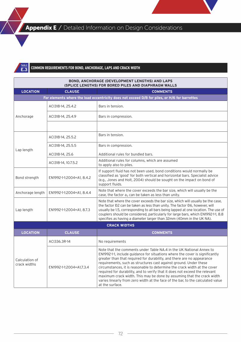
72
Appendix E / Detailed Information on Design Considerations
BOND, ANCHORAGE (DEVELOPMENT LENGTHS) AND LAPS (SPLICE LENGTHS) FOR BORED PILES AND DIAPHRAGM WALLS
LOCATION CLAUSE COMMENTS
For elements where the load eccentricity does not exceed D/8 for piles, or H/6 for barrettes
Anchorage
ACI318-14, 25.4.2 Bars in tension.
ACI318-14, 25.4.9 Bars in compression.
Lap length
ACI318-14, 25.5.2Bars in tension.
ACI318-14, 25.5.5
ACI318-14, 25.6
Bars in compression.
Additional rules for bundled bars.
ACI318-14, 10.7.5.2Additional rules for columns, which are assumed to apply also to piles.
Bond strength EN1992-1-1:2004+A1, 8.4.2
If support fluid has not been used, bond conditions would normally be classified as ‘good’ for both vertical and horizontal bars. Specialist advice (e.g., Jones and Holt, 2004) should be sought on the impact on bond of support fluids.
Anchorage length EN1992-1-1:2004+A1, 8.4.4Note that where the cover exceeds the bar size, which will usually be the case, the factor a2 can be taken as less than unity.
Lap length EN1992-1-1:2004+A1, 8.7.3
Note that where the cover exceeds the bar size, which will usually be the case, the factor α2 can be taken as less than unity. The factor α6, however, will usually be 1.5, corresponding to all bars being lapped at one location. The use of couplers should be considered, particularly for large bars, which EN1992-1-1, 8.8 specifies as having a diameter larger than 32mm (40mm in the UK NA).
CRACK WIDTHS
LOCATION CLAUSE COMMENTS
Calculation of crack widths
ACI336.3R-14 No requirements
EN1992-1-1:2004+A1,7.3.4
Note that the comments under Table NA.4 in the UK National Annex to EN1992-1-1, include guidance for situations where the cover is significantly greater than that required for durability, and there are no appearance requirements, such as structures cast against ground. Under these circumstances, it is reasonable to determine the crack width at the cover required for durability, and to verify that it does not exceed the relevant maximum crack width. This may be done by assuming that the crack width varies linearly from zero width at the face of the bar, to the calculated value at the surface.
COMMON REQUIREMENTS FOR BOND, ANCHORAGE, LAPS AND CRACK WIDTHE.3TABLE

73
Appendix E / Detailed Information on Design Considerations
Concrete Cover
In terms of structural requirements, cover is required both for durability and to provide resistance to the splitting forces generated by the reinforcement bond. For execution of deep foundations using concrete poured by tremie, provision of a suitable amount of cover, as stated in execution standards (EN 1536 and EN 1538, ACI 301), is critical to allow the concrete to flow around and completely embed the reinforcement bars to obtain dense durable concrete in this cover zone.
The greater of the individual minimum values for cover required from considerations of bond, durability and execution should be increased by an allowance for construction tolerance as shown in Section 2.3, and below.
Nominal cover = greater of minimum required for cover for durability, bond, execution + allowance for construction tolerance:-
The general recommendation of this Guide is that the minimum nominal cover for execution should be 75 mm [3in] i.e. a minimum cover of 50 mm [2 in] plus a tolerance of 25 mm [1 in].
The nominal cover should be increased in cases where the structural minimum cover e.g. as given in EN 1992, is greater than 50 mm [2 in] (as given above) by the corresponding amount.
Note 1: The minimum cover for execution should be increased if the conditions for concrete flow are considered critical. Some examples are given in EN 1536 such as where a large maximum grain size of 32 mm [1 1/4 in] is used or if the concrete viscosity is increased (e.g. where silica fume replaces cement by a considerable fraction of 5% or greater), or in soft soil without the use of a casing.
Note 2: FHWA GEC 10 suggests higher cover for larger diameter shafts i.e. 75 mm [3 in] cover for shafts of diameter not greater than 1 m [3 ft], 100 mm [4 in] cover for diameter greater than 1 m [3 ft] but not greater than 1.5 m [5 ft], and 150 mm [6 in] cover for diameter above 1.5 m [5 ft].
Note 3: EN 1536 permits the minimum concrete cover for execution to be reduced to 40 mm [1.5 in] to the external face of a permanent casing or lining, where used. It is recommended that the minimum cover of the reinforcement cage to the inner face of a casing, both temporary and permanent, should not be less than 50 mm [2 in]. An allowance for construction tolerances is not required in this case, but an additional tolerance for cage installation is still compulsory, see Figure E.1.
Note 4: The required distance between cages and joints or formwork ends are independent of the concrete cover. In accordance with EN 1538 +A1, 7.5.5.3 and 7.5.5.4 these distances should be > 100 mm [4 in] and < 200 mm [8 in] respectively.
Note 5: Many designers are reluctant to apply a large concrete cover on the basis that the crack width at the face may become excessive. This should not be a concern as crack width should only be calculated at the minimum cover position, with concrete outside that value being considered as surplus (see CIRIA Guide C760 and ACI 350).
Single Columns on Single Piles
Cage connection details can present a challenge for constructability for bored piles where a single bored pile is used to support a single column and the splice between the column and pile reinforcement occurs near the top of the pile. This detail can be particularly congested where a non-contact lap splice is used and the column reinforcement comprises a separate cage within the pile reinforcement as shown on Figure E.2. Anchor bolt connections to transmission towers, sign poles, or similar structures also can result in congestion of this type. It is especially difficult for tremie concrete to make its way through two reinforcing cages without trapping fluid contaminants at the very top of the pile.
CONCRETE COVER IN BORED PILES SUPPORTED BY A TEMPORARY CASING (SUPPLEMENTING FIGURE 3) E.1
FIGURE
cnom = cmin + Δcdev with cmin > maxcmin, structural
cmin, execution

74
Appendix E / Detailed Information on Design Considerations
The most effective solution for this situation is to provide for a construction joint at a location below the splice, so that the pile head can be trimmed and the concrete at the splice connection can be cast in the dry as conventional structural concrete. This approach typically requires that a surface casing be used to provide a stable pile excavation above the construction joint. The surface of the construction joint would typically require preparation by removing any interface layer, bleed water, or contaminated concrete prior to concrete placement at the splice. In some cases it may be possible to remove fluids and contaminated concrete within the splice zone and complete the splice while the concrete remains workable.
In some cases where the overlap into the pile is relatively short (e.g. up to 2 m [7 ft]), it may be possible to insert the inner cage into the fresh concrete after the concrete placement has been completed. Although this approach would be unwieldy with a tall column cage, it may be manageable with a short section of reinforcement used to extend above grade as a splice cage or for an anchor bolt assembly. This process (commonly referred to as “wet-sticking”) can have limitations if alignment tolerances are tight because of difficulties in precise placement and the short time window in which the concrete remains sufficiently flowable for the work to be completed.
CONNECTION DETAILS FOR A BORED PILE USED TO SUPPORT A SUPERSTRUCTURE COLUMNE.2
FIGURE
75
Appendix F
Selection of Factors and Effects on Concrete Flow
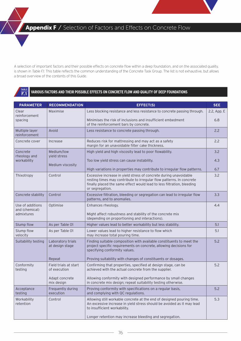
76
Appendix F / Selection of Factors and Effects on Concrete Flow
A selection of important factors and their possible effects on concrete flow within a deep foundation, and on the associated quality, is shown in Table F.1. This table reflects the common understanding of the Concrete Task Group. The list is not exhaustive, but allows a broad overview of the contents of this Guide.
PARAMETER RECOMMENDATION EFFECT(S) SEE
Clear reinforcement spacing
Maximise Less blocking resistance and less resistance to concrete passing through.
Minimises the risk of inclusions and insufficient embedment of the reinforcement bars by concrete.
2.2, App. E
6.8
Multiple layer reinforcement
Avoid Less resistance to concrete passing through. 2.2
Concrete cover Increase Reduces risk for mattressing and may act as a safety margin for an unavoidable filter cake thickness.
2.2
Concrete rheology and workability
Medium/low yield stress
Medium viscosity
High yield and high viscosity lead to poor flowability.
Too low yield stress can cause instability.
High variations in properties may contribute to irregular flow patterns.
3.2
4.3
6.7
Thixotropy Control Excessive increase in yield stress of concrete during unavoidable resting times may contribute to irregular flow patterns. In concrete finally placed the same effect would lead to less filtration, bleeding or segregation.
3.2
Concrete stability Control Excessive filtration, bleeding or segregation can lead to irregular flow patterns, and to anomalies.
3.3
Use of additions and (chemical) admixtures
Optimise Enhances rheology.
Might affect robustness and stability of the concrete mix (depending on proportioning and interactions).
4.4
Slump flow As per Table 01 Higher values lead to better workability but less stability. 5.1
Slump flow velocity
As per Table 01 Lower values lead to higher resistance to flow which may increase total pouring time.
5.1
Suitability testing Laboratory trials at design stage
Repeat
Finding suitable composition with available constituents to meet the project specific requirements on concrete, allowing decisions for specifying conformity values.
Proving suitability with changes of constituents or dosages.
5.2
Conformity testing
Field trials at start of execution
Adapt concrete mix design
Confirming that properties, specified at design stage, can be achieved with the actual concrete from the supplier.
Allowing conformity with designed performance by small changes in concrete mix design; repeat suitability testing otherwise.
5.2
Acceptance testing
Frequently during execution
Proving conformity with specifications on a regular basis, and complying with QC regulations.
5.2
Workability retention
Control Allowing still workable concrete at the end of designed pouring time. An excessive increase in yield stress should be avoided as it may lead to insufficient workability.
Longer retention may increase bleeding and segregation.
5.3
VARIOUS FACTORS AND THEIR POSSIBLE EFFECTS ON CONCRETE FLOW AND QUALITY OF DEEP FOUNDATIONSF.1TABLE
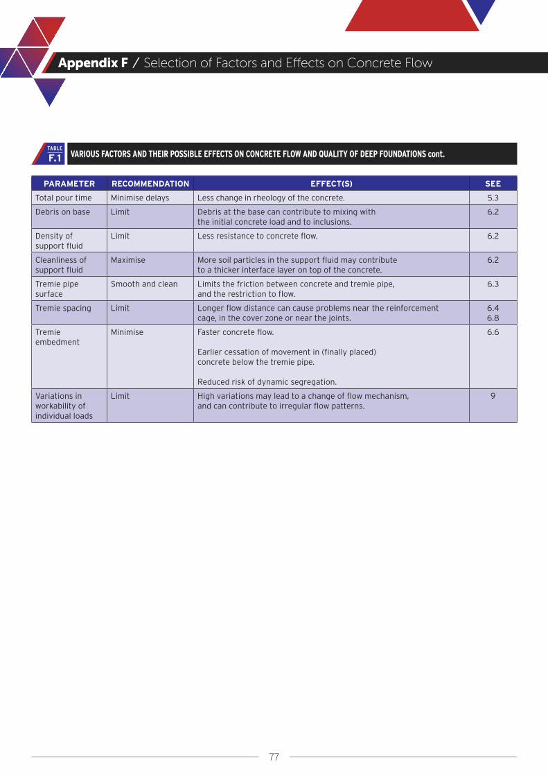
77
Appendix F / Selection of Factors and Effects on Concrete Flow
PARAMETER RECOMMENDATION EFFECT(S) SEE
Total pour time Minimise delays Less change in rheology of the concrete. 5.3
Debris on base Limit Debris at the base can contribute to mixing with the initial concrete load and to inclusions.
6.2
Density of support fluid
Limit Less resistance to concrete flow. 6.2
Cleanliness of support fluid
Maximise More soil particles in the support fluid may contribute to a thicker interface layer on top of the concrete.
6.2
Tremie pipe surface
Smooth and clean Limits the friction between concrete and tremie pipe, and the restriction to flow.
6.3
Tremie spacing Limit Longer flow distance can cause problems near the reinforcement cage, in the cover zone or near the joints.
6.46.8
Tremie embedment
Minimise Faster concrete flow.
Earlier cessation of movement in (finally placed) concrete below the tremie pipe.
Reduced risk of dynamic segregation.
6.6
Variations in workability of individual loads
Limit High variations may lead to a change of flow mechanism, and can contribute to irregular flow patterns.
9
VARIOUS FACTORS AND THEIR POSSIBLE EFFECTS ON CONCRETE FLOW AND QUALITY OF DEEP FOUNDATIONS cont.F.1TABLE

78
References
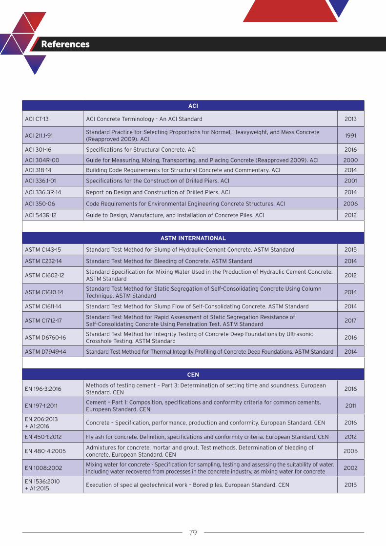
79
References
ACI
ACI CT-13 ACI Concrete Terminology - An ACI Standard 2013
ACI 211.1-91Standard Practice for Selecting Proportions for Normal, Heavyweight, and Mass Concrete (Reapproved 2009). ACI
1991
ACI 301-16 Specifications for Structural Concrete. ACI 2016
ACI 304R-00 Guide for Measuring, Mixing, Transporting, and Placing Concrete (Reapproved 2009). ACI 2000
ACI 318-14 Building Code Requirements for Structural Concrete and Commentary. ACI 2014
ACI 336.1-01 Specifications for the Construction of Drilled Piers. ACI 2001
ACI 336.3R-14 Report on Design and Construction of Drilled Piers. ACI 2014
ACI 350-06 Code Requirements for Environmental Engineering Concrete Structures. ACI 2006
ACI 543R-12 Guide to Design, Manufacture, and Installation of Concrete Piles. ACI 2012
ASTM INTERNATIONAL
ASTM C143-15 Standard Test Method for Slump of Hydraulic-Cement Concrete. ASTM Standard 2015
ASTM C232-14 Standard Test Method for Bleeding of Concrete. ASTM Standard 2014
ASTM C1602-12Standard Specification for Mixing Water Used in the Production of Hydraulic Cement Concrete. ASTM Standard
2012
ASTM C1610-14 Standard Test Method for Static Segregation of Self-Consolidating Concrete Using Column Technique. ASTM Standard
2014
ASTM C1611-14 Standard Test Method for Slump Flow of Self-Consolidating Concrete. ASTM Standard 2014
ASTM C1712-17Standard Test Method for Rapid Assessment of Static Segregation Resistance of Self-Consolidating Concrete Using Penetration Test. ASTM Standard
2017
ASTM D6760-16Standard Test Method for Integrity Testing of Concrete Deep Foundations by Ultrasonic Crosshole Testing. ASTM Standard
2016
ASTM D7949-14 Standard Test Method for Thermal Integrity Profiling of Concrete Deep Foundations. ASTM Standard 2014
CEN
EN 196-3:2016Methods of testing cement – Part 3: Determination of setting time and soundness. European Standard. CEN
2016
EN 197-1:2011Cement – Part 1: Composition, specifications and conformity criteria for common cements. European Standard. CEN
2011
EN 206:2013 + A1:2016
Concrete – Specification, performance, production and conformity. European Standard. CEN 2016
EN 450-1:2012 Fly ash for concrete. Definition, specifications and conformity criteria. European Standard. CEN 2012
EN 480-4:2005Admixtures for concrete, mortar and grout. Test methods. Determination of bleeding of concrete. European Standard. CEN
2005
EN 1008:2002Mixing water for concrete - Specification for sampling, testing and assessing the suitability of water, including water recovered from processes in the concrete industry, as mixing water for concrete
2002
EN 1536:2010 + A1:2015
Execution of special geotechnical work – Bored piles. European Standard. CEN 2015

80
References
CEN CONT.
EN 1538:2010 + A1:2015
Execution of special geotechnical work – Diaphragm Walls. European Standard. CEN 2015
EN 1992-1-1:2004 + A1:2014
Eurocode 2: Design of concrete structures – Part 11: General rules, and rules for buildings. European Standard. CEN
2014
EN 1997-1:2004 + A1:2013
Eurocode 7: Geotechnical design - Part 1: General rules. European Standard. CEN 2013
EN 12350-1 to -12
Testing fresh concrete – Parts 1 to 12. European Standard. CEN
-1 Sampling -2 Slump test -5 Flow table test -8 Self-compacting concrete. Slump-flow test -11 Self-compacting concrete. Sieve segregation test
2009 to 201020092009200920102010
EN 13263-1:2005 + A1:2009
Silica fume for concrete. Definitions, requirements and conformity criteria. European Standard. CEN
2009
EN 15167-1:2006Ground granulated blast furnace slag for use in concrete, mortar and grout. Definitions, specifications and conformity criteria. European Standard. CEN
2006
EN ISO 9001:2015 Quality management systems. Requirements. European and International Standard. CEN + ISO 2015
EN ISO 10414-1Petroleum and natural gas industries – Field testing of drilling fluids (ISO 10414:2008) Part 1: Water-based fluids
2008
CEN/TR 16639Use of k-value concept, equivalent concrete performance concept and equivalent performance of combinations concept. Technical report. CEN
2014
OTHER STANDARDS, GUIDELINES AND RECOMMENDATIONS
AASHTO R81 Standard Practice for Static Segregation of Hardened Self-Consolidating Concrete (SCC) Cylinders 2017
AASHTO T318 Standard Method of Test for Water Content of Freshly Mixed Concrete Using Microwave Oven Drying 2015
API RP 13B-1 Field testing for Water-Based Drilling Fluids. API Recommended Practice 13B-1. 4th edition, 3-2009 2009
Z17, CIATremie Concrete for Deep Foundations. Recommended Practice, Concrete Institute of Australia, Australia
2012
CIRIA C580 Embedded retaining walls – guidance for economic design. CIRIA. London, UK 2003
CIRIA C760 Guidance on embedded retaining wall design. CIRIA, London, UK 2017
DAfStb Guideline on SCC
Selbstverdichtender Beton (SVB-Richtlinie). DAfStb. Beuth. Berlin, Germany 2003
DIN 1045-2Tragwerke aus Beton, Stahlbeton und Spannbeton – Teil 2: Beton – Festlegung, Eigenschaften, Herstellung und Konformität – Anwendungsregeln zu DIN EN 206-1
2001
DFI Publication 74Industry practice standards and DFI practice guidelines for structural slurry walls. Deep Foundations Institute
2005
FHWA GEC10Drilled Shafts: Construction Procedures and LRFD Design Methods. Geotechnical Engineering Circular No. 10. Publication No. FHWA-NHI-10-016. National Highway Institute, U.S. Department of Transportation, Federal Highway Administration, Washington, D.C.
2010
Guide technique LCPCOuvrages de soutènement - Recommandations pour l’inspection détaillée, le suivi et le diagnostic des ouvrages de soutènement en parois composites – Guide technique LCPC – Laboratoire Central des Ponts et Chausssées - Paris Cedex
2003
ICE SPERW The ICE Specification for Piling and Embedded Retaining Walls. 3rd edition. ICE. UK 2017
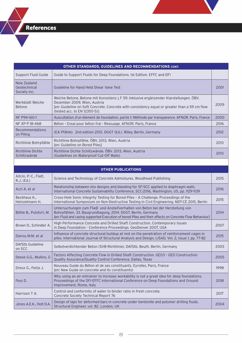
81
References
OTHER STANDARDS, GUIDELINES AND RECOMMENDATIONS CONT.
Support Fluid Guide Guide to Support Fluids for Deep Foundations. 1st Edition. EFFC and DFI
New Zealand Geotechnical Society Inc.
Guideline for Hand Held Shear Vane Test 2001
Merkblatt Weiche Betone
Weiche Betone. Betone mit Konsistenz > F 59. Inklusive ergänzender Klarstellungen. ÖBV. Dezember 2009, Wien, Austria [en: Guideline on Soft Concrete. Concrete with consistency equal or greater than a 59 cm flow (tested acc. to EN 12350-5)]
2009
NF P94-I60-1 Auscultation d’un élement de foundation, partie 1: Méthode par transparence. AFNOR. Paris, France 2000
NF XP P 18-468 Béton – Essai pour béton frai - Ressuage. AFNOR. Paris, France 2016
Recommendations on Piling
(EA Pfähle). 2nd edition 2012. DGGT (Ed.). Wiley, Berlin, Germany 2012
Richtlinie BohrpfähleRichtlinie Bohrpfähle. ÖBV. 2013, Wien, Austria[en: Guideline on Bored Piles]
2013
Richtlinie Dichte Schlitzwände
Richtlinie Dichte Schlitzwände. ÖBV. 2013, Wien, Austria(Guidelines on Waterproof Cut-Off Walls)
2013
OTHER PUBLICATIONS
Aitcin, P.-C., Flatt, R.J. (Ed.)
Science and Technology of Concrete Admixtures. Woodhead Publishing 2015
Azzi A. et alRelationship between mix designs and bleeding for SF-SCC applied to diaphragm walls. International Concrete Sustainability Conference, SCC-2016, Washington, US, pp. 1129-1139
2016
Beckhaus K., Heinzelmann H.
Cross-Hole Sonic Integrity Testing for Bored Piles – A Challenge. Proceedings of the International Symposium on Non-Destructive Testing in Civil Engineering. NDT-CE 2015, Berlin
2015
Böhle B., Pulsfort, M.Untersuchungen zum Fließ- und Ansteifverhalten von Beton bei der Herstellung von Bohrpfählen. 33. Baugrundtagung, 2014. DGGT, Berlin, Germany[en: Fluid and casing supported Execution of bored Piles and their effects on Concrete Flow Behaviour]
2014
Brown D., Schindler A.High Performance Concrete and Drilled Shaft Construction. Contemporary Issues in Deep Foundation - Conference Proceedings. GeoDenver 2007, USA
2007
Dairou M.M. et alInfluence of concrete structural buildup at rest on the penetration of reinforcement cages in piles. International Journal of Structural Analysis and Design, IJSAD, Vol. 2, Issue 1, pp. 77-82
2015
DAfStb Guideline on SCC
Selbstverdichtender Beton (SVB-Richtlinie). DAfStb. Beuth. Berlin, Germany 2003
Deese G.G., Mullins, G Factors Affecting Concrete Flow in Drilled Shaft Construction. GEO3 – GEO Construction Quality Assurance/Quality Control Conference. Dallas, Texas
2005
Dreux G., Festa J.Nouveau Guide du Béton et de ses constituants. Eyrolles, Paris, France[en: New Guide on concrete and its constituents)
1998
Feys D.Why using an air-entrainer to increase workability is not a great idea for deep foundations. Proceedings of the DFI-EFFC International Conference on Deep Foundations and Ground Improvement, Rome, Italy
2018
Harrison T A.Control and conformity of water to binder ratio in fresh concrete. Concrete Society Technical Report 76
2017
Jones A.E.K., Holt D.A.Design of laps for deformed bars in concrete under bentonite and polymer drilling fluids. Structural Engineer, vol. 82. London, UK
2004
82
References
OTHER PUBLICATIONS CONT.
Kosmatka S., et al Design and Control of Concrete Mixtures. 14th Edition, Portland Cement Association. Skokie, IL, USA 2003
Kraenkel T., Gehlen C.Rheology and Workability Testing of Deep Foundation Concrete in Europe and the US. Research Report No. 20-F-0107, Chair of Materials Science and Testing, Centre for Building Materials, Technical University of Munich
2018
Li C., et al Numerical simulation of fresh concrete flow in deep foundations, Engineering Computations 2018
Littlechild B., Plumbridge G.
Effects of construction technique on the behaviour of plain bored cast in situ piles constructed under drilling slurry, Proc of 7th Int. Conf. on Piling and Deep Foundations, Vienna, DFI, p1.6.1 to 1.6.8
1998
Loukili A. (Ed.) Les bétons auto-plaçants. Hermès Science, Lavoisier. Paris, France(en: self-consolidating concrete)
2011
Lubach A.Bentonite cavities in diaphragm walls. Case studies, process decomposition, scenario analysis and laboratory experiments
2004
Kosmatka S., et al Design and Control of Concrete Mixtures. 14th Edition, Portland Cement Association. Skokie, IL, USA 2003
Lowke, D.Sedimentationsverhalten und Robustheit Selbstverdichtender Betone (Segregation resistance and robustness of self-compacting concrete). Doctoral Thesis, Technical University of Munich
2013
Loukili A. (Ed.) Les bétons auto-plaçants. Hermès Science, Lavoisier. Paris. France (en: self-consolidating concrete) 2011
Lubach A.Bentonite cavities in diaphragm walls. Case studies, process decomposition, scenario analysis and laboratory experiments
2010
Massoussi N., et alThe heterogeneous nature of bleeding in cement pastes. Cement and Concrete Research 95, pp. 108-116
2017
Neville A.M., Brooks, J.J.
Concrete Technology. Second Edition, Pearson Education Ltd., UK 2010
Newman J., Choo, B.S. Advanced Concrete Technology, Processes (Vol 4), Chapter 12, Elsevier 2003
Niederleithinger E., et al
Crosshole sonic logging of secant pile walls a feasibility study. Proceedings of the 23rd SAGEEP Symposium on the application of geophysics to engineering and environmental problems. Environmental and Engineering Geophysical Society. Keystone, Colorado, USA
2010
Poletto R.J., Tamaro G.J.
Repairs of diaphragm walls, lessons learned. Proceedings of the 36th Annual Conference on Deep Foundations. DFI, Boston, USA
2011
Puller M. Deep Excavations: A Practical Manual (2nd Edition), Thomas Telford Publishing Ltd, London, UK 2003
Roussel N. (Ed.) Understanding the Rheology of Concrete. Woodhead Publishing Ltd., UK 2012
Roussel N., Cussigh F.Distinct-layer casting of SCC: The mechanical consequences of thixotropy. Cement and Concrete Research 38, pp. 624–632
2008
Roussel N., Gram A. (Eds.)
Simulation of Fresh Concrete Flow. State-of-the Art Report of the RILEM Technical Committee 222-SCF
2014
Rupnow T., Icenogle P.
Comparison of Conventional and Self-Consolidating Concrete for Drilled Shaft Construction. Final Report 533. Louisiana Transportation Research Center
2015
Seitz J.M., Schmidt H.-G.
Bohrpfähle. Ernst & Sohn, Berlin, Germany(Bored Piles)
2000
Sellountou A., et alThermal Integrity Profiling: A Recent Technological Advancement in Integrity Evaluation of Concrete Piles. Proceedings from the First International Conference, Seminar on Deep Foundations: Santa Cruz, Bolivia
2013
Spruit R.To detect anomalies in diaphragm walls. PhD thesis, Civil Engineering and Geosciences, TU Delft. PhD thesis, Technical University Delft, Civil Engineering and Geosciences. IPSKAMP drukkers, the Netherlands
2015
83
References
OTHER PUBLICATIONS CONT.
Thorp A., et alRecent Experience of Tremie Concrete Properties and Testing. DFI-EFFC International Conference on Deep Foundations and Ground Improvement, Rome, 5-8 June
2018
Torrenti J.M.Du béton frais au béton durci. Techniques de l’Ingénieur, website (www.techniques-ingenieur.fr), France
2009
Turner M.J.R144Integrity testing in piling practice. Report. Construction Industry Research & Information Association (CIRIA), UK
1997
Tuthill, L., et al Observations in Testing and Use of Water-Reducing Retarders. ASTM International 1960
Wallevik O.H.Rheology – A Scientific Approach to Develop Self-Compacting Concrete. Proceedings of the 3rd International Symposium on Self-Compacting Concrete. Reykjavik, Iceland
2003
Yao S. X., Bittner R. B.Underwater concrete in drilled shafts: the key issues and case histories. Contemporary Issue in Deep Foundation - Conference Proceedings, Geo-Denver 2007, USA
2007