guidance manual for electroplanting and metal finishing ... · guidance manual for electroplating...
TRANSCRIPT

Water
Guidance Manual
for Electroplating
and Metal Finishing
Pretreatment Standards
GUIDANCE MANUAL FOR
ELECTROPLATING AND METAL FINISHING PRETREATMENT STANDARDS
Prepared by The
Effluent Guidelines Division Office of Water Regulations and standards
and Permits Division
Office of Water Enforcement and Permits
February 1984
U.S. Environmental Protection Agency 401 M Street S.W.
Washington, DC 20460
UNITED STATES ENVIRONMENTAL PROTECTION AGENCY WASHINGTON. D.C. 20460
OFFICE OF WATER
MEMORANDUM
SUBJECT: Guidance Manual for Electroplating and Metal Finishing Pretreatment Standards
FROM: Martha G. Prothro, Director Permits Division (EN-336)
Jeffrey D. Denit, Director Effluent Guidelines Division (WH-552)
TO: Users of the Guidance Manual
This manual provides information to assist Control Authorities and Approval Authorities in implementing the National Categorical Pretreatment Standards for the Electroplating and Metal Finishing Point Source Categories (40 CFR Parts 413 and 433, respectively). It is designed to supplement the more detailed documents listed as references in the manual: it is not designed to replace them. If you need more complete information on a specific item, you should refer to the appropriate reference.
EPA developed this manual to fill several needs. First, it should be useful to Control Authorities in responding to most routine inquiries from regulated manufacturers. More complex inquiries may require the use of the listed references.
Second, Approval Authorities should find this manual useful in responding to specific category determination requests sub- mitted by industries under the Electroplating and Metal Finishing regulations. In addition, many integrated facilities have raised questions regarding the relationship between the Electroplating regulation and the Metal Finishing regulation and between the Metal Finishing regulation and other regulations listed in Section 433.10 of the Metal Finishing regulation. The manual will provide information on responding to category determination requests and questions from integrated facilities.

-2-
Finally, the manual addresses application of the combined wastestream formula to integrated facilities with regulated and unregulated wastestreams. It also provides current information on removal credits and the status of the fundamentally different factors variance provision in light of the recent court decision. It further explains how facilities subject to these regulations may use the certification procedure to minimize their sampling and analysis for total toxic organic pollutants.
We hope that POTWs will find this manual to be a useful tool in implementing the Electroplating and Metal Finishing Categorical Pretreatment Standards. It may also be useful in implementing other categorical pretreatment standards. Please feel free to write to either the Office of Water Regulations and Standards (WH-551) or the Office of Water Enforcement and Permits (EN-336) with suggestions, additions, or improvements.

We wish to acknowledge the considerable efforts and cooperation of the many people whose contributions helped in the successful completion of this document.
This document was prepared under the direction of Mr. Marvin Rubin, Office of Quality Review, Effluent Guidelines Division and Dr. James Gallup, National Pretreatment Coordinator. Mr. Richard Kinch of the Effluent Guide- lines Division, and Messrs. Timothy Dwyer and Robert F. Eagen, Jr. of the National Pretreatment Program are to be acknowledged for their valuable input. In addition, members of the Office of General Counsel and other members of the Effluent Guidelines Division and Office of Water Enforcement and Permits Division are acknowledged for their important contributions.
This document was prepared by JRB Associates and Whitescarver Associates, Inc. under EPA Contract No. 68-01-6514.

TABLE OF CONTENTS
PAGE
1. INTRODUCTION . . . . . . . . . . . . . . . . . . . . . . . . . . . . . . . . . . . . . . . . . . . . . . . . . . . 1-1
1.1 HISTORY OF THE ELECTROPLATING AND METAL FINISHING CATEGORICAL PRETREATMENT STANDARDS........................
2. ELECTROPLATING CATEGORICAL PRETREATMENT STANDARDS.............. 2-1
2.1 AFFECTED INDUSTRY ......................................... 2-1 2.2 EXCEPTIONS FROM REGULATION COVERAGE ....................... 2-3 2.3 PRETREATMENT STANDARDS FOR THE ELECTROPLATING CATEGORY .... 2-4 2.4 POLLUTANTS EXCLUDED FROM REGULATION ....................... 2-7 2.5 COMPLIANCE DATES .......................................... 2-7
3. METAL FINISHING CATEGORICAL PRETREATMENT STANDARDS............. 3-1
3.1 AFFECTED INDUSTRY ......................................... 3-1 3.2 EXCEPTIONS FROM REGULATION COVERAGE ....................... 3-1 3.3 PRETREATMENT STANDARDS FOR METAL FINISHING CATEGORY ....... 3-14 3.4 POLLUTANTS EXCLUDED FROM REGULATION ....................... 3-16 3.5 COMPLIANCE DATES .......................................... 3-19 3.6 ALTERNATIVE CYANIDE LIMITATION ............................ 3-19
4. TREATMENT TECHNOLOGIES . . . . . . . . . . . . . . . . . . . . . . . . . . . . . . . . . . . . . . . . . 4-1
4.1 TREATMENT OF COMMON METALS WASTES ......................... 4-1 4.2 TREATMENT OF COMPLEXED METAL WASTES ....................... 4-3 4.3 TREATMENT OF PRECIOUS METALS WASTES ....................... 4-3 4.4 TREATMENT OF HEXAVALENT CHROMIUM .......................... 4-4 4.5 TREATMENT OF CYANIDE WASTES ............................... 4-4 4.6 TREATMENT OF OILY WASTES .................................. 4-5 4.7 IN-PLANT CONTROL OF TOXIC ORGANICS ........................ 4-5 4.8 TREATMENT OF SLUDGES ...................................... 4-6 4.9 IN-PROCESS CONTROL TECHNOLOGIES ........................... 4-6
5. REQUIREMENTS OF THE GENERAL PRETREATMENT REGULATIONS . . . . . . . . . . . 5-1
5.1 INTRODUCTION .............................................. 5-1 5.2 CATEGORY DETERMINATION REQUEST ............................ 5-2
1-2

TABLE OF CONTENTS
PAGE
5.3 MONITORING AND REPORTING REQUIREMENTS OF THE GENERAL PRETREATMENT REGULATIONS . . . . . . . . . . . . . . . . . . . . . . . . . . . . . . . . . .
5.3.1 Baseline Monitoring Reports ........................ 5.3.2 Report on Compliance ............................... 5.3.3 Periodic Reports on Continued Compliance ........... 5.3.4 Notice of Slug Loading ............................. 5.3.5 Monitoring and Analysis to Demonstrate
Continued Compliance ............................... 5.3.6 Signatory Requirements for Industrial
User Reports ....................................... 5.3.7 Recordkeeping Requirements .........................
5.4 SPECIAL INDUSTRIAL SELF-MONITORING CONSIDERATIONS......... 5-7
5.4.1 Toxic Organics Certification ....................... 5-7 5.4.2 Self-Monitoring for Cyanide ........................ 5-9
5.5 APPLICATION OF THE COMBINED WASTESTREAM FORMULA ........... 5-9 5.6 REMOVAL CREDITS ........................................... 5-12 5.7 FUNDAMENTALLY DIFFERENT FACTORS VARIANCE .................. 5-21 5.8 LOCAL LIMITS .............................................. 5-22
5-2
5-2 5-5 5-6 5-6
5-6
5-7 5-7
REFERENCES . . . . . . . . . . . . . . . . . . . . . . . . . . . . . . . . . . . . . . . . . . . . . . . . . . . . . . . . . R-1

LIST OF TABLES AND FIGURES
Table
1.1
2.1
2.2
3.1
3.2
3.3
3.4
3.5
5.1
5.2
5.3
5.4
Breakdown of the Electroplating/Metal Finishing Industry.....
Pretreatment Standards for Existing Sources Electroplating Category . . . . . . . . . . . . . . . . . . . . . . . . . . . . . . . . . . . . . .
Compliance Dates for Electroplating Pretreatment Standards...
Metal Finishing Category Unit Operations.....................
Potential Wastewater Pollutants Generated by Metal Finishing Category Unit Operations . . . . . . . . . . . . . . . . . . . . . . . . . . .
Pretreatment Standards for the Metal Finishing Category......
Long Term Concentration Averages . . . . . . . . . . . . . . . . . . . . . . . . . . . . .
Compliance Dates for Metal Finishing Pretreatment Standards . . . . . . . . . . . . . . . . . . . . . . . . . . . . . . . . . . . . . . . . . . . . . . . . . . . .
Due Dates for Submission of Baseline Monitoring Reports......
Combined Wastestream Formulas . . . . . . . . . . . . . . . . . . . . . . . . . . . . . . . .
Combined Wastestream Formula Example Calculation.............
Combined Wastestream Formula Example Calculation.............
Figure
3.1 Schematic Showing Example of Overlap Coverage of Categorical Standards at Integrated Facilities. . . . . . . . . . . . . . .
4.1 Wastewater Treatment Schematic . . . . . . . . . . . . . . . . . . . . . . . . . . 4-2
Page
1-3
2-5
2-7
3-2
3-12
3-17
3-18
3-20
5-4
5-13
5-14
5-15
3-15
1. INTRODUCTION
The National Pretreatment Program establishes an overall strategy for
controlling the introduction of nondomestic wastes to publicly owned treatment
works (POTWs) in accordance with the overall objectives of the Clean Water
Act. Sections 307(b) and (c) of the Act authorize the Environmental Protec-
tion Agency to develop national pretreatment standards for new and existing
dischargers to POTWs. The Act made these pretreatment standards enforceable
against dischargers to publicly owned treatment works.
The General Pretreatment Regulations (40 CFR Part 403) establish ad-
ministrative mechanisms requiring nearly 1,700 POTWs to develop local pre-
treatment programs to enforce the general discharge prohibitions and specific
Categorical Pretreatment Standards. These Categorical Pretreatment Standards
are designed to prevent the discharge of pollutants which pass through, inter-
fere with, or are otherwise incompatible with the operation of the POTWs. The
standards are technology-based for removal of toxic pollutants and contain
specific numerical limitations based on an evaluation of specific technologies
for the particular industrial categories. As a result of a settlement agree-
ment, the EPA was required to develop Categorical Pretreatment Standards for
34 industrial categories with a primary emphasis on 65 classes of toxic pol-
lutants.
This manual will provide guidance to POTWs on the application and
enforcement of the Categorical Pretreatment Standards for the Electroplating
and Metal Finishing Categories. This document is based primarily on two
sources : Federal Register notices, which Include the official announcements
of the Categorical Standards, and the Final Development Documents for Electro-
plating and Metal Finishing, which provide a summary of the technical support
for the regulations. Additional information on the regulations, manufacturing
processes, and control technologies can be found in these sources. A listing
of the references used in the development of this manual is provided at the
end of this document.
l-l
1.1 HISTORY OF THE ELECTROPLATING AND METAL FINISHING CATEGORICAL PRETREATMENT STANDARDS
There are 13,500 plants in the electroplating/metal finishing industry.
Many discharge wastewaters from several metal finishing operations other than,
and in addition to, electroplating. Part 413 (electroplating) currently
applies only to flows from the six specified electroplating processes. These
Part 433 (metal finishing regulations) will apply to those electroplating
streams and also to wastestreams from most other metal finishing operations
within the same plants. The Part 433 PSES will apply only to plants already
covered by Part 413; however Part 433 will often cover additional wastewater
within the same plants. Thus the Part 433 limits on discharge of toxic
metals, toxic organics, and cyanide will apply to most facilities in the
electroplating/metal finishing industry.
The industry can be divided into the sectors indicated on Table 1.1.
Facilities are either “captives” (those which in a calendar year own more than
50% [area basis] of the materials undergoing metal finishing); or “job shops”
(those which in a calendar year do not own more than 50% [area basis] of ma-
terial undergoing metal finishing).
Captives can be further divided by two definitions: “integrated” plants
are those which, prior to treatment, combine electroplating waste streams with
significant process waste streams not covered by the electroplating category;
“non-integrated- facilities are those which have significant wastewater dis-
charges only from operations addressed by the electroplating category. Many
captives (50%) are “integrated” facilities. Whereas captives often have a
complex range of operations, job shops usually perform fewer operations. In
theory job shops can be divided like captives; in actuality, however, approx-
imately 97% of all job shops in this industry are “non-integrated.‘*
Pretreatment standards for the electroplating industry were first
established in 1974 but it was not until promulgation of 40 CFR Part 413 on
September 7, 1979 that Electroplating Categorical Pretreatment Standards
became a reality. The 1979 Standards established specific numerical limita-
tions for dischargers falling within seven subcategories. Shortly thereafter,

Table 1.1
Indirect dischargers (10,561)
Direct 409 job 6 dischargers IPCBM (2,909) directs
BREAKDOWN OF THE ELECTROPLATING/METAL FINISHING INDUSTRY
(Number of plants per sector 13,470)
Job shops1 and IPCBM
(3,470)
Captive facilities (lO,OOO>
Nonintegrated Integrated
3,061 job & 3,750 non- 3,750 IPCBM indirect integrated integrated
captive captive
(2) (2)
1 Independent printed circuit board manufacturers. 2 2,500 captive directs.
l-3

petitions to review the electroplating pretreatment standards were filed in
the Court of Appeals by several industry groups. EPA reached a settlement
agreement with the industry groups and agreed to adopt changes to the Stan-
dards which were promulgated on January 28, 1981. The major changes incor-
porated by the 1981 amendments to the fclectroplating Standards included:
1) Revision of the daily maximum limitation for total cyanide from 0.8 to 1.9 mg/l
2) Revision of 30-day average lirlits to 4-day average limits
3) Adoption of the concept of integrated and non-integrated facilities
4) Extension of compliance dates
5) Recognition of the development of additional pretreatment standards to be called “Metal Finishing’ which would regulate processes currently falling under electroplating as well as many other metal finishing processes. However , EPA stated that in light of the potentially severe economic impact of these anticipated regulations on the job shop (and independent printed circuit board) segment of the industry, the Agency woulc not impose more stringent pretreatment standards for that segment of the industry for several years.
In accordance with the Agency’s plan, EPA promulgated the Metal Finishing
Categorical Pretreatment Standards on July 15, 1983 as 40 CFR Part 433. The
effect of the 1983 Metal Finishing Stardards was to create a new category -
Metal Finishing - which most electroplaters would have to comply with fol-
lowing their compliance with the Electroplating Standard. These subsequent
limits would apply uniformly to discharges from electroplating and other metal
finishing operations. This would meet industry’s requests for equivalent
limits for process lines often found together and would greatly reduce the
need for the combined wastestream formula (see Section 5.5). Once the com-
pliance date for the Metal Finishing Standards is reached, all firms, con-
ducting one or more of the six basic operations of the Electroplating Category
(see Section 2.1) must come into compliance with the Metal Finishing Pretreat-
ment Standards, with the exception of existing job shop electroplaters and
independent printed circuit board manufacturers. Existing indirect job shop
electroplaters and independent printed circuit board manufacturers must still
comply with the Part 413 Electroplating Pretreatment Standards and are exempt
from the Part 433 Metal Finishing Standards.
l-4
Non-integrated and integrated electroplaters must comply with Electro-
plating Pretreatment Standards for Existing Sources (PSES) for Metals and
Cyanide by April 27, 1984, and June 30, 1984, respectively. All electro-
platers must comply with the Total Toxic Organics (TTO) PSES by no later than
July 15, 1986 (See Table 2.2).
Electroplaters subject to the Metal Finishing PSES must comply with the
Metals, Cyanide, and Final TTO PSES by no later than February 15, 1986 (See
Table 3.5). After this date, the Metal Finishing PSES supercede the Electro-
plating PSES. With the exception of plants covered by the Iron and Steel
standards, electroplaters subject to the Metal Finishing PSES must comply with
an interim TTO PSES by no later than June 30, 1984. A more complete dis-
cussion of compliance dates is presented in subsequent sections of this
manual.
l-5

2. ELECTROPLATING CATEGORICAL PRETREATMENT STANDARDS (40 CFR PART 413)
2.1 AFFECTED INDUSTRY
The Electroplating Standards are applicable to wastewater from any or all
of these six specific operations (See the Electroplating Final Development
Document).
1. Electroplating
2. Electroless Plating
3. Anodizing
4. Coatings
5. Chemical Etching and Milling
6. Printed Circuit Board Manufacturing
These six electroplating operations are briefly discussed below:
1. Electroplating is the production of a thin surface coating of one metal upon another by electrodeposition. Ferrous or nonferrous basis materials may be coated by a variety of common (copper, nickel, lead, chromium, brass, bronze, zinc, tin, cadmium, iron, aluminum or combinations thereof) or precious (gold, silver, platinum, osmium, iridium, palladium, rhodium, indium, ruthenium, or combinations thereof) metals. In electroplating, metal Ions supplied by the dissolution of metal from anodes or other pieces, are reduced on the work pieces (cathodes) while in either acid, alkaline, or neutral solutions.
The electroplating baths contain metal salts, alkalies, and other bath control compounds in addition to plating metals such as copper, nickel, silver or lead. Many plating solutions contain metallic, metallo-organic, and organic additives to induce grain refining, leveling of the plating surface, and deposit brightening.
2. Electroless Plating is the chemical deposition of a metal coating on a workpiece by immersion in an appropriate plating solution. Electricity is not involved, therefore uniform deposits are easily obtained. Copper and nickel electroless plating for printed circuit boards are the most common operations. In electroless nickel plating the source of nickel is a salt, and a reducer is used to reduce the nickel to its base state. A complexing agent is used to hold the metal ion in solution. Immersion plating, which for purposes of this
2-1

regulation is considered part of electroless plating, produces a metal deposit by chemical displacement; however, it is not an autocatalytic process but is promoted by one of the products of the reaction. Immersion plating baths are usually formulations of metal salts, alkalies and complexing agents (typically cyanide or ammonia).
3. Anodizing is an electrochemical process which converts the metal surface to a coating of an insoluble oxide. Aluminum is the most frequently anodized material. The formation of the oxide occurs when the parts are made anodic in dilute sulfuric or chromic acid solutions. The oxide layer begins formation at the extreme outer surface, and as the reaction proceeds, the oxide grows into the metal. Chromic acid anodic coatings are more protective than sulfuric acid coatings and are used if a complete rinsing of the part cannot be achieved.
Anodizing wastewater typically contains the basis material and either chromic or sulfuric acid. When dyeing of anodized coatings occurs, the wastewaters will contain chromium or other metals from the dye. Other potential pollutants include nickel acetate (used to seal anodic coatings) or other complexes and metals from dyes and sealers.
4. Coatings include chromating, phosphating, metal coloring and passivating. Pollutants associated with these processes enter the wastestream through rinsing and batch dumping of process baths. The process baths usually contain metal salts, acids, bases, and dis- solved basis materials. In chromating, a portion of the base metal is converted to a component of the protective film formed by the coating solutions containing hexavalent chromium and active organic or inorganic compounds. Phosphate coatings are formed by the immersion of steel, iron, or zinc plated steel in a dilute solution of phosphoric acid plus other reagents to condition the surfaces for cold forming operations, prolong the life of organic coatings, provide good paint bonding and improve corrosion resistance. Metal coloring involves the chemical method of converting the metal surface into an oxide or similar metallic compound to produce a decorative finish. A variety of solutions utilizing many metals may contribute to the wastestream. Passivating is the process of forming a protec- tive film on metals by immersion in an acid solution, usually nitric acid or nitric acid with sodium dichromate.
5. Etching and Chemical Milling are processes used to produce specific design configurations or surface appearances on parts by controlled dissolution with chemical reagents or etchants. Chemical etching is the same process as chemical milling except the rates and depths of metal removal are usually much greater in chemical milling. The major wastestream constituents are the dissolved basis material and etching solutions.
6. Printed Circuit Board Manufacturing involves the formation of a circuit pattern of conductive metal (usually copper) on nonconductive board materials such as plastic or glass. There are five basic steps
2-2

involved in the manufacturing of printed circuit boards: cleaning and surface preparation, catalyst and electroless plating, pattern printing and masking, electroplating, and etching.
Wastewater is produced in the manufacturing of printed circuit boards from the following processes:
a. Surface preparation - The rinses following scrubbing, alkaline cleaning, acid cleaning, etchback, catalyst application, and activation.
b. Electroless plating - Rinses following the electroless plating step.
c. Pattern plating - Rinses following acid cleaning, alkaline cleaning, copper plating, and solder plating.
d. Et thing - Rinses following etching and solder brightening.
e. Tab plating - Rinses following solder stripping, scrubbing, acid cleaning, and nickel, gold, or other plating operations.
f. Immersion plating - Rinses following acid cleaning and immersion tin plating.
Additionally, water may be used for subsidiary purposes such as rinsing away spills, air scrubbing water, equipment washing, and dumping spent process solutions. The principal constituents of the wastestreams from the printed circuit board industry are suspended solids, copper, fluorides, phosphorus, tin, palladium, and chelating agents. Low pH values are characteristic of the wastes because of the necessary acid cleaning and surface pretreatment.
In addition to the above operations, the Electroplating Standards also
apply to the related operations of alkaline cleaning, acid pickle, and
stripping when each operation is followed by a rinse.
2.2 EXCEPTIONS FROM REGULATION COVERAGE
Operations similar to electroplating which are specifically exempt from
coverage under the Electroplating Categorical Pretreatment Standards include:
1. Electrowinning and electrorefining conducted as part of nonferrrous metal smelting and refining (40 CFR Part 421);
2-3

2. Metal surface preparation and conversion coating conducted as part of coil coating (40 CFR Part 465);
3. Metal surface preparation and Lmmersfon plating or elcctroless plating conducted as a part of porcelain enameling (40 CFR Part 466);
4. Electrodeposition of active electrode materials, electroimpregnation, and electroforming conducted as part of battery manufacturing (40 CFK Part 461);
5. Metallic platemaking and gravure cylinder preparation conducted within printing and publishing facilities; and
6. Continuous strip electroplating conducted withfn iron and steel manufacturing facilities.
7. Surface treatment including anc,dizing and conversion coating con- ducted as part of aluminum forming (40 CFR Part 467).
2.3 PRETREATMENT STANDARDS FOR THE ELECTROPLATING CATEGORY
Indirect dischargers that perform electroplating operations are currently
subject to the Electroplating Categortcal Pretreatment Standards (40 CFR Part
413). The Electroplating Standards were developed based on the best practi-
cable control technology (BPT) and apply only to existing indirect sources
(PSES). EPA established Pretreatment Standards on the basis of concentration
with alternate mass-based standards for Zlectroplating. The production based
standards are based on milligrams per square meter of operation. Elect ro-
plating Standards are based on daily maximum and four day average value limits
(with four day average value limits defined as the average value from four
consecutive sampling days). The PSES limitations for electroplaters and the
alternate mass-based standards are presented in Table 2.1. Note that the
limitations and the pollutants regulated are different for dischargers of less
than 10,000 gallons per day of regulated Electroplating process wastewater as
compared to dischargers of 10,000 gallons per day or more of regulated Elec-
troplating process wastewater.
Also, all new sources which perform electroplating operations are subject
to the Metal Finishing regulations (40 CFR Part 433).
2-4

TABLE 2.1
PRETREATMENT STANDARDS FOR EXISTING SOURCES (PSES) ELECTROPLATING CATEGORY
Facilities Discharging <38,000 liters (10,000 gallons) per day
Daily Maximum Maximum
4 Day Average Pollutant (mg/l) (mg/l)
Cadmium (T) 1.2 0.7 Lead (T) 0.6 0.4 Cyanide, A 5.0 2.7 Total Toxic Organics (TTO)' 4.57 --
Facilities Discharging >38,000 liters (10,000 gallons) per day
Pollutant Daily Maximum
(mg/l)
Maximum 4 Day Average
(mg/l)
Cadmium (T) Chromium (T) Copper (T) Lead (T) Nickel (T) Zinc (T) Silver (T)2 Total Metals3 Cyanide, T Total Toxic Organic6 (TTO)'
1.2 0.7 7.0 4.0 4.5 2.7 0.6 0.4 4.1 2.6 4.2 2.6 1.2 0.7
10.5 6.8 1.9 1.0 2.13 --
Cyanide, A = Cyanide, amenable to chlorination Cyanide (T) = Cyanide, Total ('r.1 = Total
1 No regulatton of the maximum 4-day average for TTO.
'The silver pretreatment standard applies only to precious metals plating.
3 Total metals is defined as the sum of the concentration of copper, nickel, total chromium, and zinc.
2-5

TABLE 2.1 (continued)
Alternate Mass-Based Limitations For Electroplating Subcategories Discharging 38,000 liters (10,100 gallons) per day or more
Pollutant Daily Maximum Maxi mum 4 Day Average
(mg/sq m of Operation) (mg/sq m of Operation)
Electroplating, Electroplating, Electroless Electroless
Plating, Plating, Chemical Etching Printed Chemical Etching Printed
and Milling, Circuf t and Mi 1 ling, Circuit Coatings, Board Coatings, Board Anodizing Manufact.uring Anodtztng - Manufacturing
Cadmium (T) 47 Chromium, (T) 273 Copper CT) 176 Lead (T) 23 Nickel (T) 160 Zinc (T) 64 Silver (T)’ 47 Total metals2 4 10 Cyanide (T) 74
10;’ 62’1 401
53 36 5~ 37L ---
9358 169
29 I56 10 5
16 100 102 29
267 39
65 357 241
36 229 232 --- 609
89
TTO - Maximum for any one day is 2.13 mg/l
1 The silver pretreatment standard applies only to precious met,sls plating.
2 Total metals ts defined as the slim of the masses of copper, nickel, total chromium, and zinc.
2-6

2.4 POLLUTANTS EXCLUDED FROM REGULATION
The EPA excluded from regulation 7 of the 126 toxic pollutants which are
given priority consideration (antimony, arsenic, asbestos, beryllium, mercury,
selenium, and thallium). These pollutants are found in only a small number of
sources and are effectively controlled by the technologies on which the limits
are based.
2.5 COMPLIANCE DATES
The Agency divided the industry into two groups on the basis of waste-
water complexity:
a. Integrated facility - a facility which performs electroplating as only one of several operations necessary for manufacture of a product at a single physical location, which has significant quantities of process wastewater from nonelectroplating operation, and which, prior to or at the point of treatment (or proposed treatment), combines one or more electroplating process water lines with one or more plant sewers carrying process wastewater from non-electroplating manufac- turing operations.
b. Non-integrated - any facility which Is not integrated.
This division results in different compliance dates as shown in
Table 2.2, below.
TABLE 2.2
COMPLIANCE DATES FOR ELECTROPLATING PRETREATMENT STANDARDS 40 CFR PART 413
Existing Indirect Dischargers Compliance Dates
Pollutant Parameter
Non-Integrated Integrated Facilities Facilities
Metals and Cyanide April 27, 1984 June 30, 1984
Total Toxic Organics (TTO) July 15, 1986 July 15, 1986
2-7

3. METAL FINISHING CATEGORICAL PRETREATMENT STANDARDS (40 CFR PART 433)
3.1 AFFECTED INDUSTRY
The Metal Finishing Category covers wastewater discharges from 46 unit
operations, the six operations previously addressed by the Electroplating
regulation, plus an additional 40 operations. If any of the six electro-
plating operations are present, then the Metal Finishing pretreatment regula-
tions apply to wastewater from any of the 46 listed metal finishing opera-
tions. If a facility does not perform at least one of six Electroplating
operations, it is not subject to the Metal Finishing regulation. These metal
finishing unit operations are summarized and described in Table 3.1. Table
3.2 summarizes the wastewaters potentially generated by each of the metal
finishing unit operations. Since the Standards regulate processes and not
industry groups, specific SIC codes do not determine coverage.
3.2 EXCEPTIONS FROM REGULATION COVERAGE
Excluded from the Metal Finishing regulations are all existing indirect
discharging job shop electroplaters, independent printed circuit board
manufacturers, and any facility which does not perform at least one of the six
basic Electroplating processes. Job shops are defined as those facilities
which in a calendar year own 50% (area basis) or less of the material under-
going metal finishing. Independent Printed Circuit Board Manufacturers
(IPCBMs) are defined as facilities which manufacture printed circuit boards
principally for sale to other companies. These facilities remain subject only
to the Electroplating (Part 413) Standards, primarily to minimize the economic
Impact to these relatively small facilities. Also excluded from the Metal
Finishing regulations are those facilities which perform metallic platemaking
and gravure cylinder preparation conducted within printing and publishing
facilities.
3-1

TABLE 3.1. METAL FINISHING CATEGORY UNIT OPERATIONS
Unit Operations
1. Electroplating
2. Electroless Plating
3. Anodizing
4. Coatings
Summary Description of Unit Operations
The production of a thin surface coating of one metal upon another by electrodeposition. Ferrous or nonferrous basis materials may be coated by a variety of common (copper, nickel, lead, chromium, brass, bronze, zinc, tin, cadmium, iron, aluminum or combinations thereof) or precious (gold, silver, platinum, osmium, iridium, palladium, rhodium, indium, ruthenium, or combinations thereof) metals. In electroplating, metal ions supplied by the dissolution of metal from anodes or other pieces, are reduced on the work pieces (cathodes) while in either acid, alkaline, or neutral solutions.
The chemical deposition of a metal coating on a workpiece by immersion in an appropriate plating solution in which electricity is not involved. Copper and nickel electroless plating for printed circuit boards are the most common operations. Immersion plating, which for purposes of the Metal Finishing regulation is considered part of electroless plating, produces a metal deposit by chemical displacement.
An electrochemical process which converts the metal surface to a coating of an insoluble oxide. Aluminum is the most frequently anodized material. The formation of the oxide occurs when the parts are made anodic in dilute sulfuric or chromic acid solutions. The oxide layer begins formation at the extreme outer surface, and as the reaction proceeds, the oxide grows into the metal.
Any operation that includes chromating, phosphating, metal coloring and passivating. In chromating, a portion of the base metal is converted to a component of the protective film formed by the coating solutions containing hexavalent chromium and active organic or inorganic compounds. Phosphate coatings are formed by the immersion of steel, iron, or zinc plated steel in a dilute solution of phosphoric acid plus other reagents to condition the surfaces for further processing. Metal coloring involves the chemical method of converting the metal surface into an
3-2
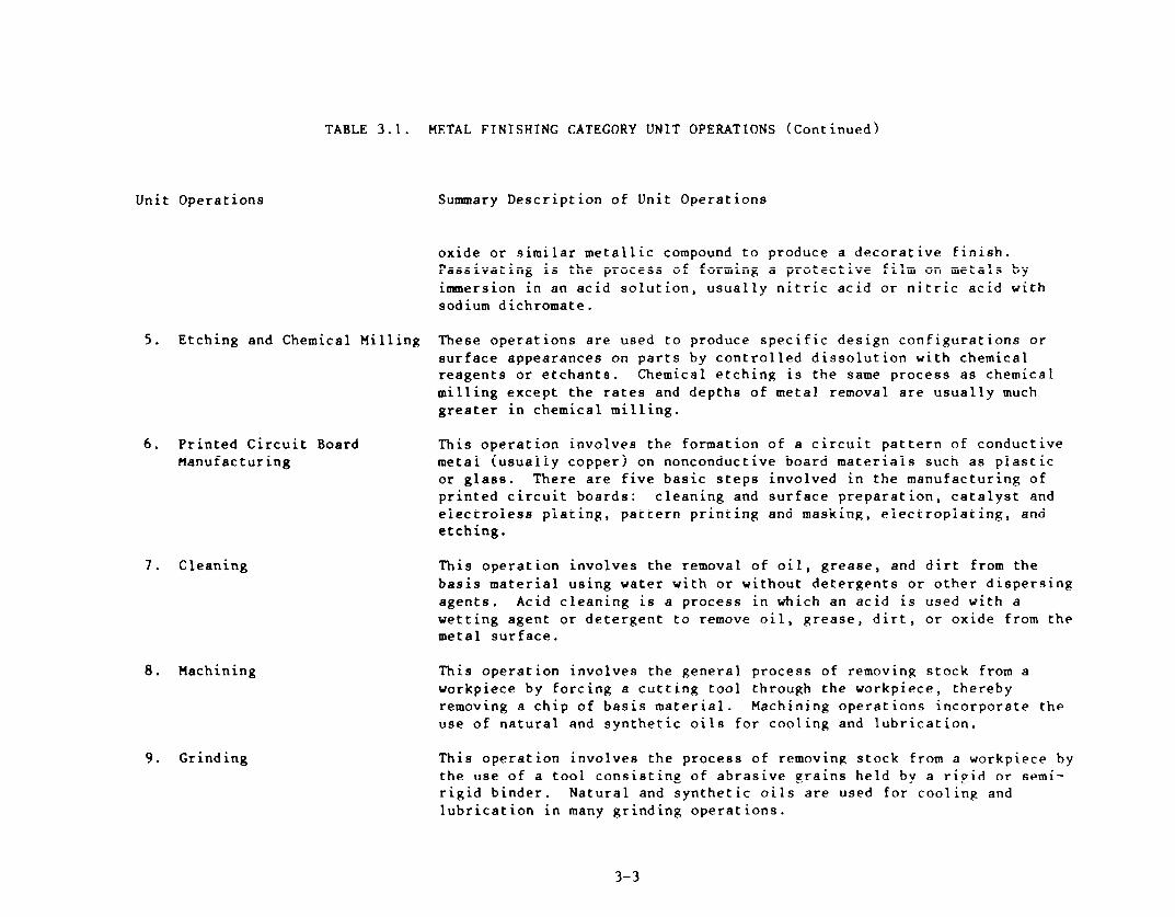
TABLE 3.1. METAL FINISHING CATEGORY UNIT OPERATIONS (Continued)
Unit Operations Summary Description of Unit Operations
oxide or similar metallic compound to produce a decorative finish. Passivating is the process of forming a protective film on metals by immersion in an acid solution, usually nitric acid or nitric acid with sodium dichromate.
5. Etching and Chemical Milling These operations are used to produce specific design configurations or surface appearances on parts by controlled dissolution with chemical reagents or etchants. Chemical etching is the same process as chemical milling except the rates and depths of metal removal are usually much greater in chemical milling.
6. Printed Circuit Board This operation involves the formation of a circuit pattern of conductive Manufacturing metal (usually copper) on nonconductive board materials such as plastic
or glass. There are five basic steps involved in the manufacturing of printed circuit boards: cleaning and surface preparation, catalyst and electroless plating, pattern printing and masking, electroplating, and etching.
7. Cleaning
8. Machining
9. Grind ing
This operation involves the removal of oil, grease, and dirt from the basis material using water with or without detergents or other dispersing agents. Acid cleaning is a process in which an acid is used with a wetting agent or detergent to remove oil, grease, dirt, or oxide from the metal surface.
This operation involves the general process of removing stock from a workpiece by forcing a cutting tool through the workpiece, thereby removing a chip of basis material. Machining operations incorporate the use of natural and synthetic oils for cooling and lubrication.
This operation involves the process of removing stock from a workpiece by the use of a tool consisting of abrasive grains held by a rigid or semi- rigid binder. Natural and synthetic oils are used for cooling and lubrication in many grinding operations.
3-3

TABLE 3.1. METAL FINISHING CATEGORY UNIT OPERATIONS (Continued)
Unit Operation5
10. Polishing
11. Barrel Finishing (or Tumbling)
12. Burnishing
13. Impact Deformation
Suwary Description of Unit Operations
This abrading operation is used to remove or smooth out surface defects (scratches, pits, tool marks, etc.) that adversely affect the appearance or function of a part. Area cleaning and washdown can produce wastes that enter wastewater streams. The wastes would belong to the cormnon metals and oily waste types.
This operation is a controlled method of processing parts to remove burrs, scale, flash, and oxides as well as to improve surface finish. Barrel finishing produces a uniformity of surface finish not possible by hand finishing and is generally the most economical method of cleaning and surface conditioning. Wastewater is generated by rinsing of parts following the finishing operation and by periodic dumping of process solutions. Contributions to the corm5on metals, hexavalent chromium, cyanide, and oily waste type5 could be made by this operation, depending IJFO~ the chemical 601ut iNIf employed.
This operation involves the process of finish sizing or smooth finishing a workpiece (previously machined or ground) by displacement, rather than removal, of minute surface irregularit ice. Wastes may come from spills, leaks, process solution dumps and post-finish rinsing and could con- tribute to the common metals, precious metals, and oily waste types depending upon the basis material finished. In addition, sodium cyanide (NaCN) may be used as a wetting agent and rust inhibitor (for steel), thus contributing cyanide wastes from this operation.
This operation involves the process of applying an impact force to a workpiece such that the workpiece is permanently deformed or shaped. Wastes containing common metals and oily wastes may come from cleaning the parts or cleanup of leaks or spills.
3-4
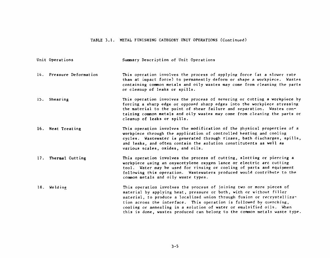
TABLE 3.1. METAL FINISHING CATEGORY UNIT OPERATIONS (Continued)
Unit Operations
14. Pressure Deformat ion
15. Shearing
16. Heat Treating
17. Thermal Cutting
18. We Id ing
Sunmary Description of Unit Operations
This operation involves the process of applying force (at a slower rate than at impact force) to permanently deform or shape a workpiece. Wastes containing common metals and oily wastes may come from cleaning the parts or cleanup of leaks or spills.
This operation involves the process of severing or cutting a workpiece by forcing a sharp edge or opposed sharp edges into the workpiece stressing the material to the point of shear failure and separation. Waste5 con- taining common metals and oily wastes may come from cleaning the parts or cleanup of leaks or spills.
This operation involves the modification of the physical properties of a workpiece through the application of controlled heating and cooling cycles. Wastewater is generated through rinses, bath discharges, spills, and leaks, and often contain the solution constitutents as well as various scales, oxides, and oils.
This operation involves the process of cutting, slotting or piercing a workpiece using an oxyacetylene oxygen lance or electric arc cutting tool. Water may be used for rinsing or cooling of parts and equipment following this operation. Wastewaters produced would contribute to the common metals and oily waste types.
This operation involves the process of joining two or more pieces of material by applying heat, pressure or both, with or without filler material, to produce a localized union through fusion or recrystalliza- tion across the interface. This operation is followed by quenching, cooling or annealing in a solution of water or emulsified oils. When this is done, wastes produced can belong to the common metals waste type.
3-5

TABLE 3.1. METAL FINISHING CATEGORY UNIT OPERATIONS (Continued)
Unit Operations
19. Brazing
20. Soldering
21. Flame Spraying
22. Sand Blasting
Summary Description of Unit Operations
This operation involves the process of joining metals by flowing a thin, capillary thickness layer of nonferrous filler metal into the space
between them. Bonding results from the intimate contact produced by the dissolution of a small amount of base metal in the molten filler metal, without fusion of the base metal. The term brazing is used where the temperature exceeds 425’C (800’F). This operation is followed by quenching, cooling or annealing in a solution of water or emulsified oils. When this is done, wastes produced can belong to the coaanon metals waste type.
This operation involves the process of joining metals by flowing a thin (capillary thickness) layer of nonferrous filler metal into the space between them. Bonding results from the intimate contact produced by the dissolution of a small amount of base metal in the molten filler metal, without fusion of the base metal. The ter!!! SO!dCriCg iS USC: Wlirlt! i.ht’
temperature range falls below 425°F (800°F). This operation is followed by quenching, cooling or annealing in a solution of water or emulsified oils. When this is done, wastes produced can belong to the common metals waste type.
This operation involves the process of applying a metallic coating to a workpiece using finely powdered fragments of wire, together with suitable fluxes, which are projected through a cone of flame onto the workpiece. This operation is followed by quenching, cooling or annealing in a solution of water or emulsified oils. When this is done, wastes produced can belong to the common metals waste type.
This operation involves the process of removing stock, including surface films, from a vorkpiece by the use of abrasive grains pneumatically impinged against the workpiece.
3-6
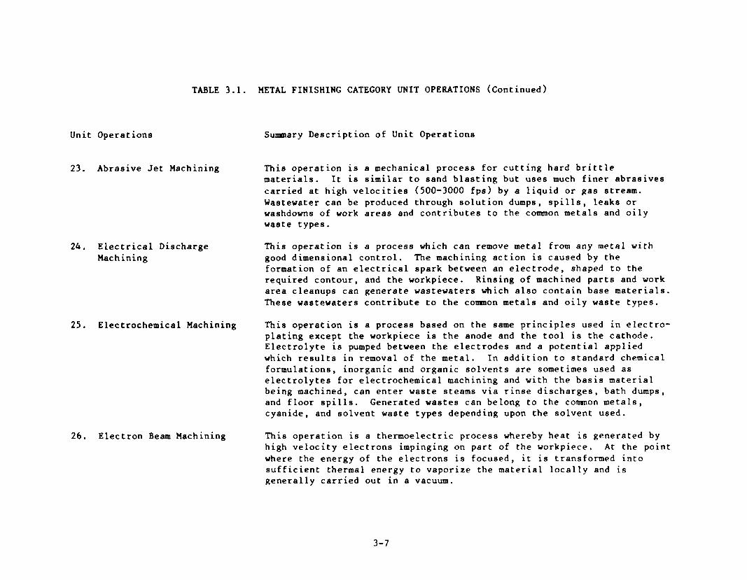
TABLE 3.1. METAL FINISHING CATEGORY UNIT OPERATIONS (Continued)
Unit Operations
23. Abrasive Jet Machining
24. Electrical Discharge Machining
Surmnary Description of Unit Operations
This operation is a mechanical process for cutting hard brittle materials. It is similar to sand blasting but uses much finer abrasives carried at high velocities (500-3000 fps) by a liquid or gas stream. Wastewater can be produced through solution dumps, spills, leaks or washdowns of work areas and contributes to the common metals and oily waste types.
This operation is a process which can remove metal from any metal with good dimensional control. The machining action is caused by the formation of an electrical spark between an electrode, shaped to the required contour, and the workpiece. Rinsing of machined parts and work area cleanups can generate wastewaters which also contain base materials. These wastewaters contribute to the cormnon metals and oily waste types.
25. Electrochemical Machining This operation is a process based on the same principles used in electro- plating except the workpiece is the anode and the tool is the cathode. Electrolyte is pumped between the electrodes and a potential applied which results in removal of the metal. In addition to standard chemical formulations, inorganic and organic solvents are sometimes used as electrolytes for electrochemical machining and with the basis material being machined, can enter waste steams via rinse discharges, bath dumps, and floor spills. Generated wastes can belong to the cormnon metals, cyanide, and solvent waste types depending upon the solvent used.
26. Electron Beam Machining This operation is a thermoelectric process whereby heat is generated by high velocity electrons impinging on part of the workpiece. At the point where the energy of the electrons is focused, it is transformed into sufficient thermal energy to vaporize the material locally and is generally carried out in a vacuum.
3-7

TABLE 3.1. METAL FINISHING CATEGORY UNIT OPERATIONS (Continued)
Unit Operations
27. Laser Beam Machining
28. Plasma Arc Machining
29. Ultrasonic Machining
30. Sinter ing
31. Laminating
32. Hot Dip Coating
Sumnary Description of Unit Operations
This operation is the process whereby a highly focused monochromatic collimated beam of light is used to remove material at the point of impingement on a workpiece. Laser beam machining is a thermoelectric process with material removal largely accomplished by evaporation, although some material is removed in the liquid state at high velocity.
This operation is the process of material removal or shaping of a workpiece by a high velocity jet of high temperature ionized gas. A gas (e.g., nitrogen, argon, or hydrogen) is passed through an electric arc causing it to become ionized and raised to temperatures in excess of 16,649”C (30,OOO’F). The relatively narrow plasma jet melts and displaces the workpiece material in its path.
This operation is a mechanical process designed to effectively machine hard, brittle materials. It removes luateriai by the use of abrasive grains which are carried in a liquid between the tool and the work, and which bombard the work surface at high velocity.
This operation is the process of forming a mechanical part from a powdered metal by fusing the particles together under pressure and heat. The temperature is maintained below the melting point of the basis metal.
This operation is the process of adhesive bonding layers of metal, plastic, or wood to form a part. Water is not often used in this operation; however, occasional rinsing or cooling may occur in conjunc- t ion with laminating. The waste generated could contribute to the common metals and oily waste types.
This operation is the process of coating a metallic workpiece with another metal to provide a protective film by immersion in a molten bath. Galvanizing (hot dip zinc) is the most common hot dip coating. Water is used for rinses following precleaning and sometimes for quenching after coating. These wastewaters can contribute to the common metals waste type.
3-8

TABLE 3.1. METAL FINISHING CATEGORY UNIT OPERATIONS (Continued)
Unit Operations
33. Sputtering
34. Vapor Plating
35. Thermal Infusion
36. Salt Bath Descal ing
37. Solvent Degreasing
Summary Description of Unit Operations
This operation is the process of covering a metallic or non-metallic workpiece with thin films of metal. The surface to be coated is bombarded with positive ions in a gas discharge tube, which is evacuated to a low pressure.
This operation is the process of decomposition of a metal or compound upon a heated surface by reduction or decomposition of a volatile compound at a temperature below the melting point of either the deposit or the basis material.
This operation is the process of applying a fused zinc, cadmium, or other metal coating to a ferrous workpiece by inbuing the surface of the workpiece with metal powder or dust in the presence of heat.
This operation is the process of removing surface oxides or scale from a workpiece by immersion of the workpiece in a molten salt bath or a hot salt solution. Molten salt baths are used to remove oxides from stain- less steels and other corrosion-resistant alloys. These baths contain molten salts, caustic soda, sodium hydride and chemical additives. These contaminants (and a small amount of base material and oils) enter waste- water streams through rinsing, spills, leaks, batch dumps of process solutions, and improper handling of sludge produced by the process. Wastewaters produced by salt bath descaling contribute to the cormnon metals and oily waste types.
This operation is a process for removing oils and grease from the surface of a workpiece by the use of organic solvents such as aliphatic petroleums, aromatics, oxygenated hydrocarbons, halopenated hydrocarbons, and combinations of these classes of solvents. These pollutants can enter wastewater streams and contribute to the toxic organic waste type.
3-9

TABLE 3.1. METAL FINISHING CATEGORY UNIT OPERATIONS (Continued)
Unit Operations
38. Paint Stripping
Sumnary Description of Unit Operations
This operation is the process of removing an organic coating from a workpiece. The stripping of such coatings is usually performed with caustic, acid, solvent, or molten salt. The stripping wastes can contain any of the constituents of the paint being removed, as well as a small amount of the basis material beneath the paint and the constitutents of the stripping solution. Wastes are primarily generated by rinsing and can also contain small amounts of emulsified oils. Wastes produced belong to the common metals and oily waste types and may contain toxic organice.
39. Painting This operation is the process of applying an organic coating to a workpiece.
40. Electrostatic Painting This operation involves the application of electrostatically charged paint particles to an oppositely charged workpiece followed by thcrma! fusing of the paint particles to form a cohesive paint film.
41. Electropainting
42. Vacuum Metalizing
43. Assembly
This operation is the process of coating a workpiece by either making it anodic or cathodic in a bath that is generally an aqueous emulsion of the coating material. Electropainting is used primarily for primer coats because it gives a fairly thick, highly uniform, corrosion resistant coating in relatively little time. Ultrafiltration is used in connection with electropainting to concentrate paint solids. Wastewaters from these unit operations can contribute to the common metals, hexavalent chromium, and solvent waste types.
This operation is the process of coating a workpiece with metal by flash heating metal vapor in a high-vacuum chamber containing the workpiece. The vapor condenses on all exposed surfaces.
This operation involves the fitting together of previously manufactured parts or components into a complete machine, unit of a machine, or structure.
3-10
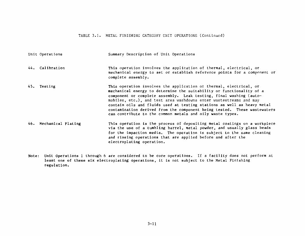
TABLE 3.1. METAL FINISHING CATEGORY UNIT OPERATIONS (Continued)
Unit Operations
44. Calibration
45. Testing
46. Mechanical Plating
Summary Description of Unit Operations
This operation involves the application of thermal, electrical, or mechanical energy to set or establish reference points for a compnnent or complete assembly.
This operation involves the application ot thermal, electrical, or mechanical energy to determine the suitability or functionality of a component or complete assembly. Leak testing, final washing (auto- mobiles, etc.), and test area washdowns enter wastestreams and may contain oils and fluids used at testing stations as well as heavy metal contamination derived from the component being tested. These wastewaters can contribute to the common metals and oily waste types.
This operation Is the process of depositing metal coatings on a workpiece via the use of a tumbling barrel, metal powder, and usually glass beads for the impaction media. The operation is subject to the same cleaning and rinsing operations that are applied before and after the electroplating operation.
Note : Unit Operations 1 through 6 are considered to be core operations. If a facility does not perform at least one of these six electroplating operations, it is not subject to the Metal Finishing regulation.
3-11
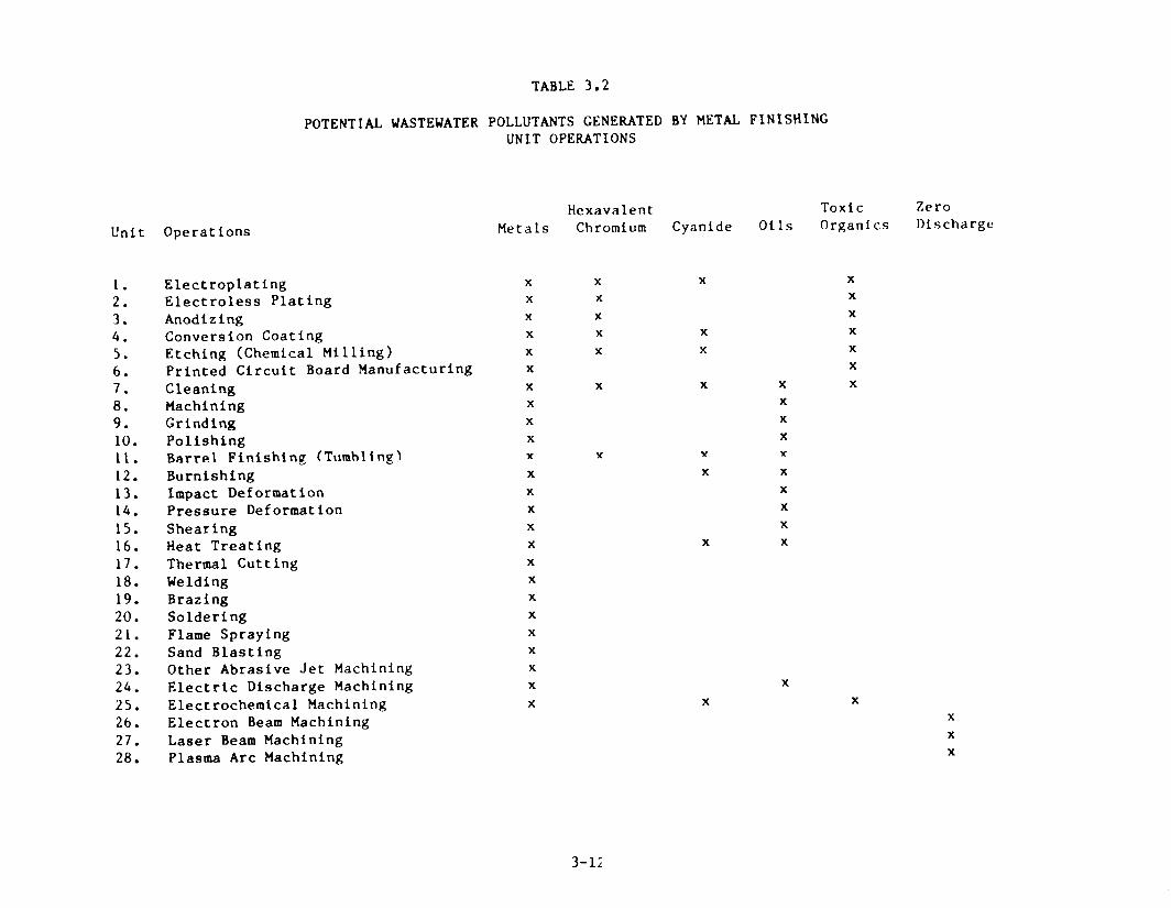
Unit Operations
1. Electroplating 2. Electroless Plating 3. Anodizing 4. Conversion Coating 5. Etching (Chemical Milling) 6. Printed Circuit Board Manufacturing 7. Cleaning 8. Machining 9. Grinding 10. Polishing 11. Barrel Finishing (Tumhltng) 12. Burnishing 13. Lmpact Deformation 14. Pressure Deformation 15. Shearing 16. Heat Treating 17. Thermal Cutting 18. Welding 19. Brazing 20. Soldering 21. Flame Spraying 22. Sand Blasting 23. Other Abrasive Jet Machining 24. Electric Discharge Machining 25. Electrochemical Machining 26. Electron Beam Machining 27. Laser Beam Machining 28. Plasma Arc Machining
POTENTIAL WASTEWATER
TABLE 3.2
POLLUTANTS GENERATED BY METAL FINISHING UNIT OPERATIONS
Hexavalent Metals Chromium Cyanide
Y
X
X X X
X X
X X
X X X
X X X
X
X X X
X
X
X
Y Y
X
X
X
X
X
X
X
X
X
X
X
X
X
X
X
X
Oils Toxic Zero Organics Discharge
X
X
X
X
Y
X
X
X
X
X
X
X
3-1;
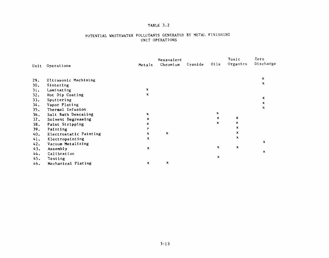
Unit Operations
TABLE 3.2
POTENTLAL WASTEWATER POLLUTANTS GENERATED BY METAL FLNISHLNG UNIT OPERATIONS
29. Ultrasonic Machining 30. Sintering 31. Laminating 32. Hot Dip Coating 33. Sputtering 34. Vapor Plating 35. Thermal Infusion 36. Salt Bath Descaling 37. Solvent Degreasing 38. Paint Stripping 39. Painting 40. Electrostatic Painting 41. Electropainting 42. Vacuum Metalizing 43. Assembly 44. Calibration 45. Testing 46. Mechanical Plating
Hexavalent Toxic Zero Metals Chromium Cyanide Oils Organics Discharge
X
X
X
X
X
X X
X
X
X
X
X
X
X
3-13

In certain case’s, another Categorical Pretreatment Standard may also
cover wastewater discharges from metal fin.shing operations. In these
situations, the more specific standards will apply to those metal finishing
wastestreams which appear to be covered by both standards. The fol lowing
regulations take precedence over the Metal Finishing regulation.
Nonferrous Smelting and Kefining (40 CFK Part 421)
Coil Coating (40 CFK Part 465)
Porcelain Enameling (40 CFK Part 466)
Battery Xanufacturing (40 CFK Part 461)
Iron and Steel Manufacturing (40 (:FK Part 420)
Metal Casting Foundries (40 CFK PiIt-t $64)
Aluminum Forming (40 CFK Part 4h7)
Copper Forming (40 CFK Part 468)
Plastic Molding and Forming (40 C:K f’art 463)
Electrical and Electronic Components (40 CFK Part 469)
Nonferrous Forming (40 CFK Part 471 )
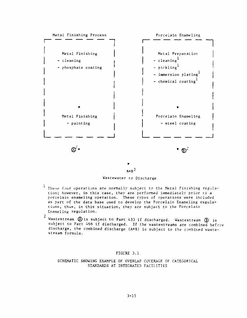
For example, if a plant performs R clvnning and phosphnte coatin)r
operation. in preparation for painting and also performs cleaning:, pickling,
immersion coating, and chemical coating 2s part of a porcelain enameling
process, then the !letal Finishing PStS apply to the discharge from the
cleaning and phosphate coating operation. while the Porcelain EnamelinK PSES
apply to the discharge from application of the porcelain enamel and also the
preparatory operations of cleaning, pick.ing, immersion plating, and chemical
coating operation. Normally, the metal :)reparation operations (cleaning,
pickling, immersion plating, and chemical coating) would he subject to the
Metal Finishing regulation. However, he:ause the Porcelain Enameling rcgula-
tions specifically include those operations performed in preparation for the
porcelain enameling operation, the Porcelain Enameling regulation takes prcce-
dencc for those wastestreams (See Figure 3.1).
3.3 PRETREATMENT STANDARDS FOR THE MET&L FINISHING CATEGORY
The Metal Finishing Standards (40 CFR Part 433) establish pretreatment
standards for new and existing facilities performing electroplating and other
3-14
Metal Finishing Process
r----- 1
Metal Finishing I - cleaning
- phosphate coating I
I
I
I
w 1
Metal Finishing I - painting
I
L----- A
Porcelain Enameling mm---
. 1 I Metal Preparation
I - cleaning1 I
I I - pickling' I - immersion plating1
I - chemical coating1 I
I
w
I
I
Porcelain Enameling
I
1 - steel coating
. I
.4+B*
Wastewater to Discharge
1 These four operations are normally subject to the Metal Finishing repula- tion; however, in this case, they are performed imediately prior to a porcelain enameling operation. These types of operations were included as part of the data base used to develop the Porcelain Enameling regula- tions, thus, in this situation, they are subject to the Porcelain Enameling regulation.
2 Wastestream @is subject to Part 433 if discharged. subject to Part 466 if discharged.
Wastestream @ is If the wastestreams are combined before
discharge, the combined discharge (A+B) is subject to the combined waste- stream formula.
FIGURE 3.1
SCHEMATIC SHOWING EXkMPLE OF OVERLAP COVEIUCE OF CATEGORICAL STANDARDS AT INTEGRATED FACILITIES
3-15

metal finishing operations. These standards are BAT-equivalent and represent
the best available technology economically achievable. All existing indirect
discharging electroplating facilities (except job shop elcctroplaters and
TPCBMs) must first comply with the Electroplating (Part 413) and then with the
Metal Finishing (Part 433) regulations. Another exception is continuous strip
electroplating at Iron and Steel Mills which is subject only to the Vetal
Finishing regulation; this unit operation is not subject to the Electroplating
regulation. The limits apply uniformly to discharges from all electroplating
and other metal finishing operations. The uniformity in standards meets
Industry requests for equivalent limits for process lines often found to-
gether. The Metal Finishing Standards also reduce the need to use the Com-
bined Wastestream Formula. No production based standards were developed for
the Metal Finishing (Part 433) Regulation. The Metal Finishing standards are
based on the 99th percentile of expected variations from observed long-term
unconstructed averages. They include dail.1 maximums and maximum monthly
(statistically based on 10 samples per month) average concentration limita-
tions. The PSES and PSNS limitations for netal finishing facilities are
presented in Table 3.3. If a plant intends to consistently comply with the
regulatory limit it should use the long term concentration average as the
basis for design and operation. Table 3.4 presents long-term concentration
averages which were found to be attainable by the technology EPA assessed.
They are presented as guidance to dischargers and control authorities.
The pretreatment standards for new scurces (PSNS) apply to electroplating
and metal finishing facilities which begar their operation after August 31,
1982, the date of the proposed regulation. The PSNS for metal finishing
facilities are the same as those for existing sources, with the exception that
cadmium must be controlled more stringently.
3.4 POLLUTANTS EXCLUDED FROM REGULATION
The EPA excluded from regulation 7 01’ the 126 toxic pollutants which are
given priority consideration (antimony, arsenic, asbestos, beryllium, mercury,
selenium, and thalllum). These pollutants are found in only a small number of
sources and are effectively controlled by the technologies on which the limits
are based.
3-16

TABLE 3.3
Pollutant
PRETREATMENT STANDARDS FOR THE METAL FINISHING CATEGORY 40 CFR PART 433
PRETREATMENT STANDARDS FOR EXISTING SOURCES (PSES)
Cadimium (T) 0.69 Chromium (T) 2.77 Copper CT) 3.38 Lead (T) 0.69 Nickel (T) 3.98 Silver (T) 0.43 Zinc (T) 2.61 Cyanide, total 1.20 Total Toxic Organics (interim) 4.57 Total Toxic Organics (final) 2.13
Alternative to total cyanide: Cyanide, amenable to chlorination
Daily Maximum Monthly Maximum (mg/l) Average (mg/l)
0.26 1.71 2.07 0.43 2.38 0.24 1.48 0.65
-- --
0.86 0.32
PRETREATMENT STANDARDS FOR NEW SOURCES (PSNS)
Pollutant Daily Maximum Monthly
Maximum (mg/l) Average (mg/l)
Cadmium (T) 0.11 0.07 Chromium (T) 2.77 1.71 Copper (T) 3.39 2.07 Lead (T) 0.69 0.43 Nickel (T) 3.98 2.38 Silver (T) 0.43 0.24 Zinc (T) 2.61 1.48 Cyanide, total 1.20 0.65 Total Toxic Organlcs 2.13 --
Alternative to total cyanide: Cyanide, amenable to chlorination 0.86 0.32
Note: No maximum monthly average TTO concentration regulated. CT) = total.
3-17

TABLE 3.4
LONG TERM CONCENTUTION AVERAGES
Pollutant of Pollutant Property
Long Term Concentration
Average Milligrams
Per Liter (mg/l)
Cadmium (T)' 0.13 Chromium (T) 0.572 Copper (T) 0.815 Lead (T) 0.20 Nickel (T) 0.942 Silver OT) O.U96 Zinc (T) 0.549 Cyanide (T) 0.18 Cyanide, A 0.06 TTO (raw water) 1.08 TTO (effluent) 0.34
1 Cadmium (T) for new sources is 0.058 mg/l.
3-18
3.5 COMPLIANCE DATES
All industries subject to the Electroplating Standards (except job shop
electroplaters and IPCBMs) will have to comply with the Metal Finishing (Part
433) regulations. The control of toxic organics is an additional requirement
for facilities currently under Electroplating PSES. Compliance was found to
be achievable with good management practices (recovering solvents for contract
hauling or reclamation) and at low costs. An interim TTO limit based solely
on achieving compliance with good housekeeping practices before end-of-pipe
treatment is required to be in-place, and was established to prevent organics
from being completely uncontrolled during the time before final compliance.
The Metal Finishing compliance dates are shown in Table 3.5.
3.h ALTEKNATIVE CYANIDE LIMITATION
An alternative cyanide limit is available for facilities with significant
forms of complcxed cyanide (i.e. iron cyanides) not controllable by the tcch-
nology basis. These complexed forms are less toxic but may still undergo
transformation to the more toxic free cyanide form in the waterways. Before
allowing the cyanide amenable alternative, the Control Authority should con-
sider possible water quality impacts due to the discharge of cyanide. Complex
cyanides can be controlled by the addition of ferrous sulfate to the precipi-
tation/clarification system.
3-19
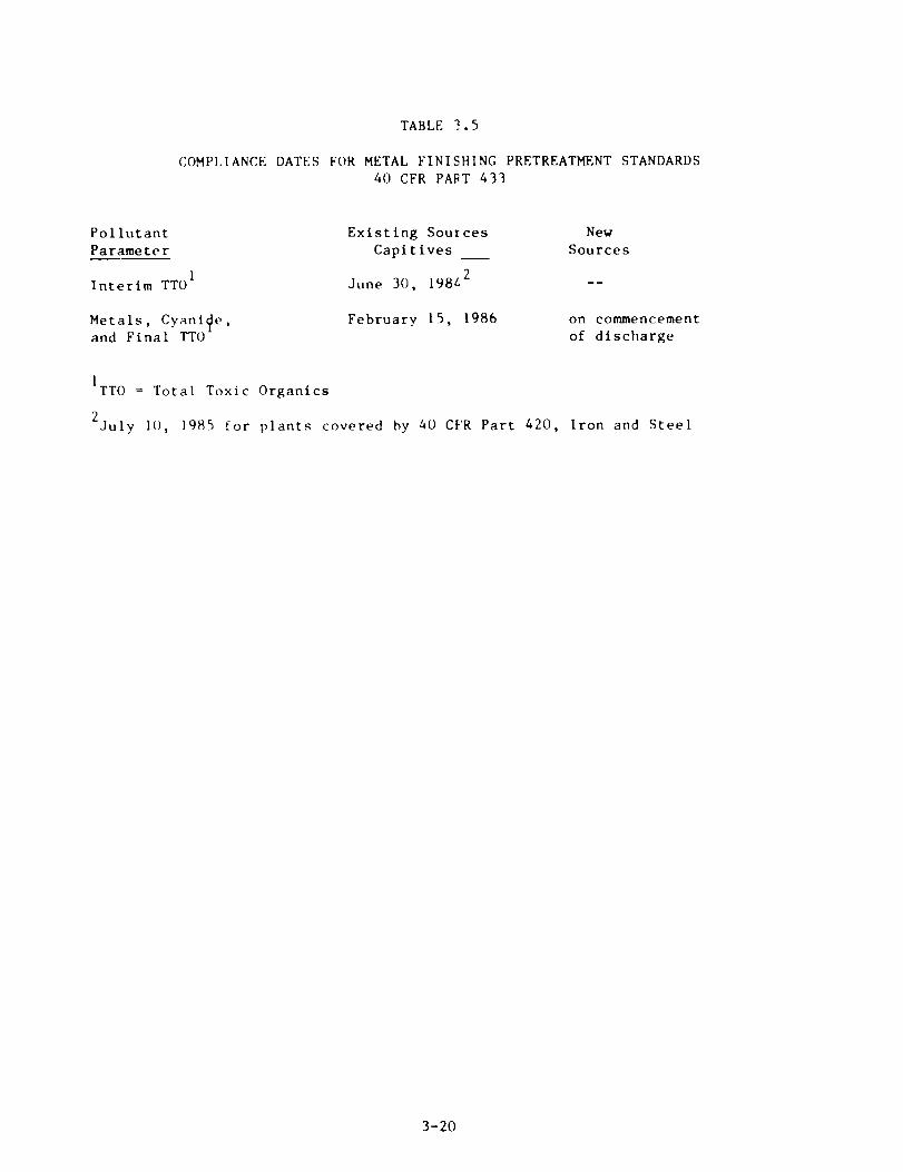
TABLE 2.5
COMPLIANCE DATES FOR METAL FINISHING PRETREATMENT STANDARDS 40 CFR PART 433
Pollutant Parameter -~
Interim TTO'
Existing Sources New Capitives Sources
June 30, 198L2 --
Metals, CyaniQe, and Final TTO
February 15, 1986 on commencement
of discharge
1 TTO = Total Toxic Organics
2 July 10, 1985 for plants covered hy 40 CI'R Part 420, Iron and Steel
3-20

4. TREATMENT TECHNOLOGIES
The treatment technologies described in this section are currently used
by metal finishers/electroplaters to remove or recover wastewater pollutants
normally generated. Figure 4.1 is an example of the current technology com-
monly used for treatment of metal finishing wastewater. As indicated, waste-
stream segregation allows the recovery of precious metals, the reduction of
hexavalent chromium, the destruction of cyanide, and the removal and recovery
of oils prior to the removal of common metals. Wastestream segregation can
reduce the flow of wastewater to the treatment system and, accordingly, reduce
the cost of treatment.
4.1 TREATMENT OF COMMON METALS WASTE
The technology basis for the pretreatment standards consists of hydroxide
precipitation followed by sedimentation. Hydroxide precipitation is used to
precipitate dissolved metals by chemical addition so that they can be removed
by physical means such as sedimentation or filtration. Hexavalent chromium is
not removed by this treatment system and cyanide will interfere with the
system’s ability to remove the dissolved metals. These raw waste types should
be treated before entering this system.
The EPA also considered but rejected the addition of filtration to the
selected technology basis to remove additional suspended solids (such as metal
hydroxides) which did not settle out in the clarifier. It may be appropriate
in cases where there are specific ambient water quality problems. The tech-
nology basis treatment system plus in-plant cadmium controls (such as evapora-
tive recovery and ion exchange) was used as the technology basis for new
source pretreatment standards.
Alternative treatment methods for common metals removal, to be used in
conjunction with or in place of the preceeding methods, include peat adsorp-
tion, insoluble starch xanthate filtration, sulfide precipitation, flotation,
and membrane filtration.
4-1

FIGURE 4.1
WASTEWATER TREATMENT SCHEMATIC
4-2

4.2 TREATMENT OF COMPLEXED METAL WASTES
Complexed metals are tied up by chemicals (complexing agents such as
ammonia and citric acid) which prevent the metals from settling out of
solution. Complexed metal wastes are a product of electroless plating,
immersion plating, etching and printed circuit board manufacturing. Metals
tied up in solution counteract the conventional precipitation technique. As a
result, segregated treatment of the complexed metal wastes is recommended.
High pH precipitation is a process involving the addition of chemicals
which drastically increase the pH to around 12, prompting a shift in the
complex dissociation equilibrium and resulting in the production of free metal
ions. The metal ions can then be precipitated by available hydroxide ions and
removed by sedimentation.
The chemical reduction process adds chemicals to lower the pH of the
wastestream (to break up the various metal complexes) followed by the addition
of a reducing agent to reduce the metals to an oxidation state which permits
precipitation of the metals. Additional chemicals to raise the pH nrc then
added to form metallic precipitates which settle out of solution. Media or
membrane filtration is an alternate method to sedimentation for solids
removal.
Modifying the hydroxide precipitation process by substituting sulfide
precipitation can improve system performance in the removal of complexcd heavy
metals. The ferrous sulfate technique is capable of achieving low metal
solubilities in spite of the presence of certain complexing agents.
4.3 TREATMENT OF PRECIOUS METALS WASTES
Treatment of precious metals consists of the technology basis for common
metals wastes plus precious metals recovery including evaporation, ion
exchange, and electrolytic recovery. Evaporation is used to recover precious
metals by boiling off the water portion of the precious metal solution and
removing the metal.
4-3

Ion exchange is the process in which ions, held by electrostatic forces
to charged functional groups on the surface of an ion exchange resin, are
exchanged for ions of similar charge from the solution in which the resin is
immersed. Ion exchange is commonly used for precious metal recovery,
especially gold.
Electrolytic recovery is particularl!l applicable to precious metals
recovery because the valuable precious metals offer a faster payback on
equipment and energy costs. The process consists of a dragout rinse after the
plating step and an off line electrolytic recovery tank.
4.4 TREATMENT OF HEXAVALENT CHROMIUM
The treatment of hexavalent chromium involves reducing hexavalent
chromium to trivalent chromium and removal with a conventional precipitation-
solids removal system. Reduced (trivalenr) chromium is able to be separated
from solution in conjunction with other metallic salts by alkaline precipita-
tion. In most cases, gaseous sulfur dioxide is used as the reducing agent in
the reduction of hexavalent chromium whic‘l enables the trivalent chromium to
be separated from solution by alkaline precipitation.
Alternative hexavalent chromium treatment techniques include
electrochemical chromium reduction, regeneration, evaporation, and ion
exchange.
4.5 TREATMENT OF CYANIDE WASTES
Treatment of cyanide is almost exclusively performed by alkaline
chlorination which focuses upon oxidizing the cyanide which is amenable to
chlorination. The destruction of cyanide results in products of carbon
dioxide and nitrogen. Additionally, ferrous sulfate may be used to precipi-
tate complexed cyanides.
Alternative treatment techniques for the destruction of cyanide include
oxidation by ozone, ozone with ultraviolet radiation, hydrogen peroxide, and
electrolytic oxidation.
4-4
4.6 TREATMENT OF OILY WASTES
Techniques commonly used by electrolaters and metal finishers to remove
oils include skimming, coalescing, emulsion breaking, flotation, centrifu-
gation, ultrafiltration, and reverse osmosis. Treatment of oily wastes is
most efficient and cost effective if oils are segregated from other wastes and
treated separately. The process of separation varies depending on the type of
oil Involved.
4.7 IN-PLANT CONTROL OF TOXIC ORCANICS
The primary control technology for toxic orgnnics is proper storage of
concentrated toxic organics without discharging directly into wastestreams and
segregation from other wastes that will enter the waste treatment system.
Spent degreasing solvents may he segregated from other wastes by providing and
identifying the necessary storage containers, training personnel in the use of
the techniques, and holding periodic check-ups to ensure that proper segre-
gat ion is occrirri ng. The separate waste solvents can then be recovered
on-site or contract hauled.
Using cleaning techniques that require no solvents will eliminate or
reduce the quantity of toxic organics found in wastewater. Cleaning tech-
niques may include wiping, immersion, spray techniques using water, alkaline
and acid mixtures, and solvent emulsions.
Toxic organics that enter the wastestreams can be removed by treatment
technologies used for the control of other pollutants. Toxic organics tend to
be more soluble in oil and grease than in water. Thus removal of oil and
grease will reduce the discharge of toxic organics. Other possible mechanisms
for removal inclrrde adsorption, settling, and volatilization, which can occur
during treatment of metals, cyanide, and oil and grease.
Specific treatment technologies which are not part of the technology
basis of the regulation but are applicable for the treatment of TTO include
carbon adsorption and reverse osmosis, resin adsorption, ozonation, chemical
oxidation, and aerobic decomposition.
4-5
4.8 TKEATMENT OF SLUDGES
Sludges are created by waste treatment technologies which remove solids
from wastewater. Sludge thickening is used to concentrate dilute sludges by a
mechanical device such as a vacuum filter or centrifuge. Doubling the solids
content reduces capital and operating costs and reduces costs for hauling.
Pressure filtration is achieved by pumping the liquid through a filter materi-
al which is impenetrable to the solid phase. Sludge bed drying is employed to
reduce the water content of sludges so that they can be mechanically collected
for removal. Sludge may then be transported to landfills or incinerated.
Additional removal methods for industrial waste sludges include chemical
containment, encapsulation, fixation, and thermal conversion.
4.9 IN-PROCESS CONTROL TECHNOLOGIES
In-process control techniques have been developed and are being utilized
by electroplaters and metal finishers. These techniques deal with reducing
water usage, reducing drag out of pollutants and efficient handling of process
wastes and include:
- Flow reduction through efficient rinsing
- Countercurrent and static rinsing
- Process bath conservation
- Waste oil segregation
- Process bath segregation
- Process modification
- Cutting fluid cleaning
- Integrated waste treatment
- Good housekeeping
Reducing the water usage at metal finishing facilities is the most
important control and results in reduced pollutant discharge and consequently
reduced costs for wastewater treatment. It is estimated that rinse steps
consume most of the water used at metal finishing facilities. Therefore,
efficient rinse systems would lead to the greatest water use reductions.
Several rinsing techniques are currently used at metal finishing facilities.
4-6

Of these, the countercurrent rinse provides for the most efficient water
usage, and consists of only one fresh water feed introduced in the last tank.
The dead or static rinse is applicable for initial rinsing after metal plating
and allows for easier metals recovery and lower water usage.
4-7
5. REQUIREMENTS OF THE GENERAL PRETREATMENT REGULATIONS
5.1 INTRODUCTION
This section provides a brief overview of the General Pretreatment
Regulations and identifies those provisions of the Regulations which have a
direct bearing on the application and enforcement of Categorical Pretreatment
Standards for the Electroplating and Metal Finishing category.
The General Pretreatment Regulations for Existing and New Sources (40 CFR
Part 403) establish the framework and responsibilities for implementation of
the National Pretreatment Program. The effect of 40 CFR Part 403 is essen-
tially three-fold. First, the General Pretreatment Regulations establish
general and specific discharge prohibitions as required by Sections 307(b) and
(c) of the Clean Water Act. The general and specific prohibitions are de-
scribed in Section 403.5 of the Pretreatment Regulations and apply to all
nondomestic sources introducing pollutants into a POTW whether or not the
source is subject to Categorical Pretreatment Standards.
Second, the General Pretreatment Regulations establish an administrative
mechanism to ensure that National Pretreatment Standards (Prohibited Discharge
Standards and Categorical Pretreatment Standards) are applied and enforced
upon industrial users. Approximately 1,700 POTWs are required to develop a
locally run pretreatment program to ensure that non-domestic users comply with
applicable pretreatment standards and requirements.
Third, and most importantly for the purposes of this guidance manual, the
General Pretreatment Regulations contain provisions relating directly to the
implementation and enforcement of the Categorical Pretreatment Standards.
Reporting requirements, local limits, monitoring or sampling requirements, and
category determination provisions are discussed. POTW representatives should
refer to 40 CFR Part 403 for specific language and requirements where appro-
priate.
5-1

5.2 CATEGORY DETERMINATION REQUEST
An existing industrial user (IU) or its POTW may request written
certification from EPA or the delegated State specifying whether or not the
industrial user falls within a particular industry category or subcategory and
is subject to a categorical pretreatment standard. Although the deadline for
submitting a category determination request by existing industrial users
subject to the electroplating and metal finishing categorical pretreatment
standards has passed, a new industrial user or its POTW may request this
certification for a category determination anytime prior to commencing its
discharge. The contents of a category determination request and procedures
for review are presented in Section 403.0(a) of the General Pretreatment
Regulations.
5.3 MONITORING AND REPORTING REQUIREMENTS OF THE GENERAL PRETREATMENT REGULATIONS
In addition to the requirements contained in the Electroplating and Metal
Finishing Categorical Pretreatment Standards, industrial users subject to
these Standards must fulfill the reporting requirements contained in Section
403.12 of the General Pretreatment Regulations. These requirements include
the submission of baseline monitoring reports, compliance schedules, compli-
ance reports (initial and periodic), notices of slug loading, and record-
keeping requirements. Each of these reporting requirements is briefly
summarized below.
5.3.1 Baseline Monitoring Reports
All industrial users subject to Categorical Pretreatment Standards must
submit a baseline monitoring report (BMR) to the Control Authority. The
purpose of the BMR is to provide information to the Control Authority to
document the industrial user’s current compliance status with a Categorical
Pretreatment Standard. The Control Authority is defined as the POTW if it has
an approved pretreatment program, otherwise the BMR will be submitted to the
State (if the State has an approved State Pretreatment Program) or to the EPA
Region. Additional guidance on BMR reporting is available from the EPA
Regional Pretreatment Coordinator.
5--2

BMR Due Dates
Section 403.12(b) requires that BMRs be submitted to the Control
Authority within 180 days after the effective date of a Categorical Pretreat-
ment Standard or 180 days after the final administrative deciston made upon a
category determination request [403.6(a)(4)], whichever is later. Table 5.1
shows the respective due dates for electroplating and metal finishing BMRs.
BMR Content --
A BMR must contain the following information as required by Section
403.12(b).
1. Name and address of the facility, including names of operator(s) and owner(s).
2. List of all environmental control permits held by or for the facility.
3. Brief description of the nature, average production rate and SIC code for each of the operation(s) conducted, including a schematic process diagram which indicates points of discharge from the regulated processes to the POTW.
4. Flow measurement information for regulated process streams discharged to the municipal system. Flow measurements of other wastestreams will be necessary if application of the combined wastestream formula is necessary.
5. Identification of the pretreatment standards applicable to each regulated process and results of measurements of pollutant concen- trations and/or mass. All samples must be representative of daily operations and results reported must include values for daily maximum and average concentration (or mass, where required). Where the flow of the regulated stream being sampled is less than or equal to 250,000 gallons per day, the industrial user must take three samples within a two week period. Where the flow of the stream is greater than 250,000 gallons per day, the industrial user must take six sam- ples within a two week period. If samples cannot be taken immediate- ly downstream from the regulated process and other wastewaters are mixed with the regulated process, the industrial user should measure flows and concentrations of the other wastestreams sufficient to allow use of the combined wastestream formula. Requirements for demonstrating compliance with TTO standards are discussed in Section 5.4.1.
5-3

TABLE 5.1
DUE DATES FOR SUBMISSION OF BASELINE MONITORING REPORTS
Electroplating (Part 413)
Metals and Cyanide
Electroplating (Part 413)
TTO
Existing Indirect Dischargers -----------------------------------------------------------------------------
Non-integrated Integrated Job Shops h Job Shops Non-integrated Integrated
IPCBH’s IPCBH’s Captives Captives --_-----_--------_------------------------------------------------------------
September 12, 1981 June 25, 1983 September 12, 1981 June 25, 1983
February 24, 1984 February 24, 1984
Metal Finishing (Part 433)
Metals, Cyanide, and TTO -- a- February 24, 1984 February 24, 1984
Note: If a request for a category determination has been made, then the BMR is due 180 days after the final decision on the category determination.
5-4
6. Statement of certification concerning compliance or noncompliance with the Pretreatment Standards.
7. If not in compliance, a compliance schedule must be submitted with the BMR that describes the actions the user will take and a timetable for completing those actions to achieve compliance with the standard. This compliance schedule must contain specific increments of progress in the form of dates for the commencement and completion of major events, however, no increment of the schedule shall exceed 9 months. Within 14 days of each completion date in the schedule, the indus- trial user shall submit a progress report to the Control Authority indicating whether or not it complied with the increment of progress to be met on such date, and, if not, the date on which it expects to comply with this increment of progress and the steps being taken to return to the schedule.
BMR Reporting of Toxic Organics
Since promulgation of the Metal Finishing pretreatment standards, some
questions have been raised regarding BMR reporting of total toxic organics
(TTO). BMR sampling requirements clearly apply to all regulated metals.
However, since monitoring for toxic organics can be expensive, BMR sampling
and analysis for TTO will only be required for those organics “which would
reasonably be expected to be present” in the industrial user’s effluent [Sec-
tion 413.03(c)]. For routine compliance monitoring, not BMR monitoring, the
regulations allow for the IU to certify that the regulated toxic organics are
not used at the facility or to present a plan demonstrating appropriate con-
trols to prevent organic compounds from entering the wastestream. Even if the
industrial user expects to use the certification procedure to demonstrate
regular compliance with the TTO limitation, the user must still sample and
analyze for any toxic organic “reasonably expected to be present” for the
purposes of the baseline monitoring report. If no toxic organic8 are used or
expected to be discharged, then no TTO monitoring is required for the BMR.
5.3.2 Report on Compliance
Within 90 days after the compliance date for the Electroplating and Metal
Finishing Pretreatment Standards or in the case of a New Source following
commencement of the introduction of wastewater into the POTW, any industrial
user subject to the Standards must submit to the Control Authority a “report
on compliance” that states whether or not applicable pretreatment standards
5-5

are being met on a consistent basis. The report must indicate the nature and
concentration of all regulated pollutants in the facility’s regulated process
wastestreams; the average and maximum daily flows of the regulated streams;
and a statement of whether compliance is consistently being achieved, and if
not, what additional operation and maintenance and/or pretreatment is nece?
sary to achieve compliance. See 40 CFR 403.12(d).
5.3.3 Periodic Reports on Continued Compliance
Unless required more frequently by the Control Authority, all industrial
users subject to the Electroplating and Metal Finishing Categorical Pretreat-
ment Standards must submit a biannual “perl odic compliance report*’ during the
months of June and December. The report shall indicate the precise nature and
concentrations of the regulated pollutants in its discharge to the POTW, the
average and maximum daily flow rates of the facility, the methods used by the
indirect discharger to sample and analyze the data, and a certification that
these methods conformed to those methods outlined in the regulations. See 40
CFR 403.12(e).
5.3.4 Notice of Slug Loading
Section 403.12(f) requires industrial users to notify the POTW imme-
diately of any slug loading of any pollutant, including oxygen demanding
pollutants (BOD, etc.) released to the POTS system at a flow rate and/or
pollutant concentration which will cause interference with the POTW.
5.3.5 Monitoring and Analysis to Demonstrate Continued Compliance
Section 403.12(g) states that the frequency of monitoring to demonstrate
continued compliance shall be prescribed in the applicable Pretreatment Stan-
dard. Neither the Electroplating nor Metal Finishing Pretreatment Standard
establish any monitoring frequency. Therefore, the appropriate Control Auth-
ority must establish the monitoring frequency to adequately demonstrate that
indirect dischargers subject to these pretreatment standards are in compliance
with the applicable standards. Unless otterwise noted in the appropriate
paragraph of Section 403.12, the monitorirg frequency established by the Con-
trol Authority shall be used in the baseline monitoring report (403.12(b)(5)),
5-6

the report on compliance with categorical pretreatment standard deadline
(403.12(d)), and the periodic reports on continued compliance (403.12(e)).
Sampling and analysis shall be in accordance with the procedures estab-
lished in 40 CFR Part 136 and any amendments to it or shall be approved by
EPA. When Part 136 techniques are not available or are inappropriate for any
pollutant, then sampling and analysis shall be conducted in accordance with
procedures established by the POTW or using any validated procedure. However,
all procedures for sampling and analysis not included in Part 136 must be
approved by EPA.
5.3.6 Signatory Requirements for Industrial User Reports
All reports submitted by industrial users (BMR, Initial Report on
Compliance, and Periodic Reports, etc.) must be signed by an authorized
representative in accordance with Section 403.12(k).
5.3.7 Recordkeeping Requirements
Any industrial user subject to the reporting requirements of the General
Pretreatment Regulations shall maintain records of all information resulting
from any monitoring activities required by 403.12 for a minimum of three years
[403.12(n)]. These records shall be available for inspection and copying by
the Control Authority.
5.4 SPECIAL INDUSTRIAL SELF-MONITORING CONSIDERATIONS
5.4.1 Toxic Organics Certification
In lieu of monitoring for TTO, the Control Authority may allow dis-
chargers subject to Electroplating and Metal Finishing regulations to certify
that no dumping of toxic organics to the wastestream has occurred. In cases
where monitoring to determine TTO compliance is necessary, sampling and
analysis for TTO will only be required for those organics “which would
reasonably be expected to be present” in the industrial user’s effluent
[Section 413.03(c)]. When dischargers request that no monitoring be required,
they must submit a toxic organic management plan that specifies the toxic
organic compounds used, the method of disposal used (instead of dumping into
5-7
wastestreams), and procedures for assuring that toxic organics do not routine-
ly spill or leak into wastewater discharged to the POTW. This certification
is added as a commt?nt to the baseline monitoring report as well as periodic
reports.
A toxic management plan provides methods for the reduction of toxics in
effluents and assists industrial facilities in achieving compliance with
Categorical Pretreatment Standards. An example of a toxic organic management
plan that is required when industrial users wish to certify that no discharge
of toxic pollutants has occurred is presented below.
The plan has three basic steps:
Step 1 - Process engineering analysis should consist of:
a. An examination of published reports on the specific industry;
b. A water flow diagram to identify all possible wastewater sources;
C. A list of raw materials used in the industrial processes, including chemical additives, water treatment chemicals and cleaning agents, and the wastewater stream that each material potentially enters;
d. Comparison of the toxics found in the effluent with the list of raw materials and selection of the most probable wastewater source;
e. Evaluation of the toxics found in the effluent, but not on the raw materials list and determination of those formed as reaction products or by-products;
f. Examination of sources such as equipment corrosion or raw materials impurities contributing inorganic pollutants.
Step 2 - Pollutant control evaluaticn should be determined on a case-by-
case basis and may include:
a. Inplant process modification, ircluding chemical substitution, partial or complete recycling, reuse, neutralization, ion exchange, or operation changes.
5-8

Step 3 - Toxics reduction evaluation report is submitted to the Control
Authority and contains:
a. Identification of source(s) of pollutant(s).
b. Control options explored.
C. Effectiveness of control options in meeting effluent limits.
d. Industrial user’s choice of options and the projected schedule for achieving necessary control.
In certain cases, the industrial user will not achieve compliance with
the effluent standard. In these cases, additional evaluations will be
necessary.
5.4.2 Self-Monitoring for Cyanide
For facilities subject to Metal Finishing regulations, self-monitoring
for cyanide must be conducted after cyanide treatment and before dilution with
other wastestreams. Alternatively, samples may be taken of the final effluent
if the plant limitations are adjusted based on the dilution ratio of the
cyanide wastestream flow to the effluent flow.
5.5 APPLICATION OF THE COMBINED WASTESTREAM FORMULA
One provision of the General Pretreatment Regulations that will often be
necessary for POlWs and industries to properly monitor and report on compli-
ance with Categorical Pretreatment Standards is the Combined Wastestream
Formula (CWF) 140 CFR 403.6(e)]. The CWF is a mechanism for calculating
appropriate limitations specified in applicable regulations to a wastewater in
which process wastestreams are mixed with regulated, unregulated or dilution
streams, thereby resulting in a mixed effluent. The CWF is applied to the
mixed effluent to account for the presence of the additional wastestreams.
The following definitions and conditions are important to the proper use
of the CWF.
5-9

Definitions
l Regulated Process Wastestream - an industrial process wastestream regulated by National Categorical Pretreatment Standards.
l Unregulated Process Wastestream - al industrial process wastestream that is not regulated by a categorical standard.
Note: Definitions apply to individual pollutants. A wastestream from a process may be “regulated” for one pollutant and “unregulated” for another.
0 Dilute Wastestream - Boiler blowdown, sanitary wastewater, noncontact cooling water or blowdown, and Paragraph 8 excluded wastestreams containing none of the regulated pollutant or only trace amounts of it.
0 Concentration-based Limit - a limit based on the relative strength of a pollutant in a wastestream, usually expressed in mg/l (lb/gal).
l !lass-based Limit - a limitation based on the actual quantity of a pollutant in a wastestream, usually expressed in mg/some unit of production for a given operation such as square meter (lb/square foot per operation).
CWF Conditions
To ensure proper application of the Cb’F, the following conditions must be
met by a municipality and its industries [LO CFR 403.6(e)]:
l Alternative discharge limits that are calculated in place of a Categorical Pretreatment Standard must be enforceable as Categorical Standards.
l Calculation of alternative limits must be performed by the Control Authority (POTW) or by the industrial user with written permission from the POTW.
0 Alternative limits must be established for all regulated pollutants in each of the regulated processes.
0 The Control Authority and/or the industrial user may use mass-based limitations in place of the concen:ration-based limitations, when they are provided for by a given Categorical Pretreatment Standard such as electroplating, as long as a prior agreement exists between the regulated industrial user and the municipality that is receiving these wastes.
l Both daily maximum and long-term average (usually monthly) alternative limits must be calculated for each regulated pollutant.
5-10

0 If process changes at an industry warrant, the Control Authority may recalculate the alternative limits at its discretion or at the request of the industrial user. The new alternative limits must be calculated and become effective within 30 days of the process change.
l The Control Authority may impose stricter alternative limits, but may not impose alternative limits that are less stringent than the calculated limits.
l A calculated alternative limit cannot be used if it is below the analytical detection limit for that pollutant. If a calculated limit is below the detection limit, the Ill must either: 1) not combine the dilute streams before they reach the combined treatment facility, or 2) segregate all wastestreams entirely.
l The categorical standards of the regulated wastestreams which are applied to the CWF must be consistent in terms of the number of samples the standard is based on. Electroplating wastestreams are regulated by a 4-day average standard and are not consistent with other categorical standards regulated by a maximum monthly average (based on 10 sample days) standard. According to 40 CFR Part 413.04, if a non-electroplating wastestream is regulated by a monthly average standard and is combined with an electroplating wastestream, monthly standards rather than 4-day average standards are to be used in calculating an alternative limit with the CWF. Also, if two electro- plating wastestreams regulated under different subcategories of the electroplating regulations are combined, the 4-day limits may be used to calculate the alternate limits, unless an additional wnstestre:.m subject to monthly standards is added. The following equivalent monthly averages (based on 10 sample days per month) have been developed for use in the CWF:
Pollutant Equivalent Monthly
Average (mg/l)
Cadmium (T > 0.63 Chromium (T 1 3.56 Copper (T) 2.44 Lead (T) 0.37 Nickel (‘I) 2.38 Zinc (T) 2.37 Silver (T) 0.63 Total Metals 6.26 Cyanide, A 2.37 Cyanide (T) 0.87
5-11

Monitoring Requirements For Industrial Users Using the CWF
Self-monitoring requirements by an industrial user are necessary to
ensure compliance with the alternative ca:egorical limit. Because neither
the Metal Finishing nor Electroplating Pretreatment Standards include self-
monitoring requirements, the Control Authority will establish minimum self-
monitoring requirements.
Application of the CWF
The actual combined wastestream foraulas are presented in Table 5.2.
Tables 5.3 and 5.4 present an example of how the CWF is used to calculate
alternative limits and four example calculations applied to specific electro-
plating/metal finishing situations. Three of the examples differ because of
the individual compliance deadlines for the different categorical pretreatment
standards. The fourth example represents an example showing conversion from a
production (mass) based standard to a concentration based standard. It is
important to remember that when two or more regulated wastestreams are mixed
prior to treatment, before using the CWF it is necessary to determine which
pretreatment regulation applies to each regulated wastestream before they are
mixed.
5.6 REMOVAL CREDITS
A removal credit allows a POTW to provide categorical industrial users of
its system with a credit (in the form of adjusted categorical pretreatment
standards) for removal of pollutants by the POTW. Industrial users receiving
such a credit are allowed to discharge to the POTW greater quantities of regu-
lated pollutants than otherwise permitted by applicable categorical standards.
Whether or not to seek authority to grant removal credits is completely at the
discretion of the POTW. Section 403.7 cf the General Pretreatment Regulations
establishes the conditions under which a POTW would obtain approval to grant
removal credits and specifies the means by which these removal credits are to
be determined.
In 1977, Congress amended section ?07(b) of the Clean Water Act to
provide for removal credits. EPA originally implemented that provision and
established the conditions under which 1’OlW.s could obtain authorization to
5-12

TABLE 5.2
COMBINED WASTESTREAM FORMULAS
Alternative Concentration Limit Formula:
c = i=l CIFi \ / Ft - Fd
\
t N X
ct - alternative concentration limit for the pollutant
5 - Categorical Pretreatment Standard concentration limit for the pollutant In regulated stream i
Fl - average dally flow (at least 30 day average) of regulated stream i
Fd - average daily flow (at least 30 day average) of dilute wastestream
Ft - average daily flow (at least 30 day average) through the combined
treatment facility (including regulated, unregulated and dilute wastestreams)
N - total number of regulated streams
Alternate Mass Limit Formula
N Mt = \‘
i-l
X
/ Ft - Fd \
N ,v
\ I=1 Fi
/
M t
- alternative mass limit for the pollutant
5 - Categorical Pretreatment Standard mass limit for the pollutant in
regulated stream I
Fi - average dally flow (at least 30 day average) of regulated stream i
Fd - average daily flow (at least 30 day average) of dilute wastestream
F t
- average daily flow (at least 30 day average) through the combined treatment facility (including regulated, unregulated and dilute wastestreams)
N - total number of regulated streams.
5-13

TABLE 5.3
COMBINED WASTESTREAM FORMULA EXAMPLE CALCULATION
The following examples provide the calculations for determining alternat
discharge limits using the combined wastestream formula. The examples assume
combinations of various industries with the following wastestreams:
Industrial Category
(Subcategory)
Electroplating (Common Metals)
Wastestream Type
Regulated
?letal Finishing Regulated
(Electroplating)1
(Coating and Painting)’
Porcelain Enameling Regulated (Steel-coating only)
Copper Forming Regulated
Sanitary Waste Dilution
Daily Max. Flow Zn Limit (mgd 1 (q/l >
0.4 4.22
0.4 2.61
0. 1 2.61
0.075 1.333
0.4 Mass IProduc 4
tion Based
August 15, 1986
0.05 N/A N/A
Compliance Date
June 30, 1984
February 15, 1986
November 25, 1985
1 These are not subcategorles; they are metal finishing processes.
2 Alternate production based limit = 164 mg/m2 plated.
3 Alternate Mass/Production based limits = 53.3 mg/m2 for preparation and 0.85
mg/m2 for coating.
4 Mass/Production based limits = 0.943 mug/off-kg of copper heat treated for
solut ton heat treatment.
The calculated alternate discharge 1imi:s (En cwf) In the following examples
are based on phased compliance dates for Electroplating, Porcelain Enameling,
and Metal Ffnishing.
5-14
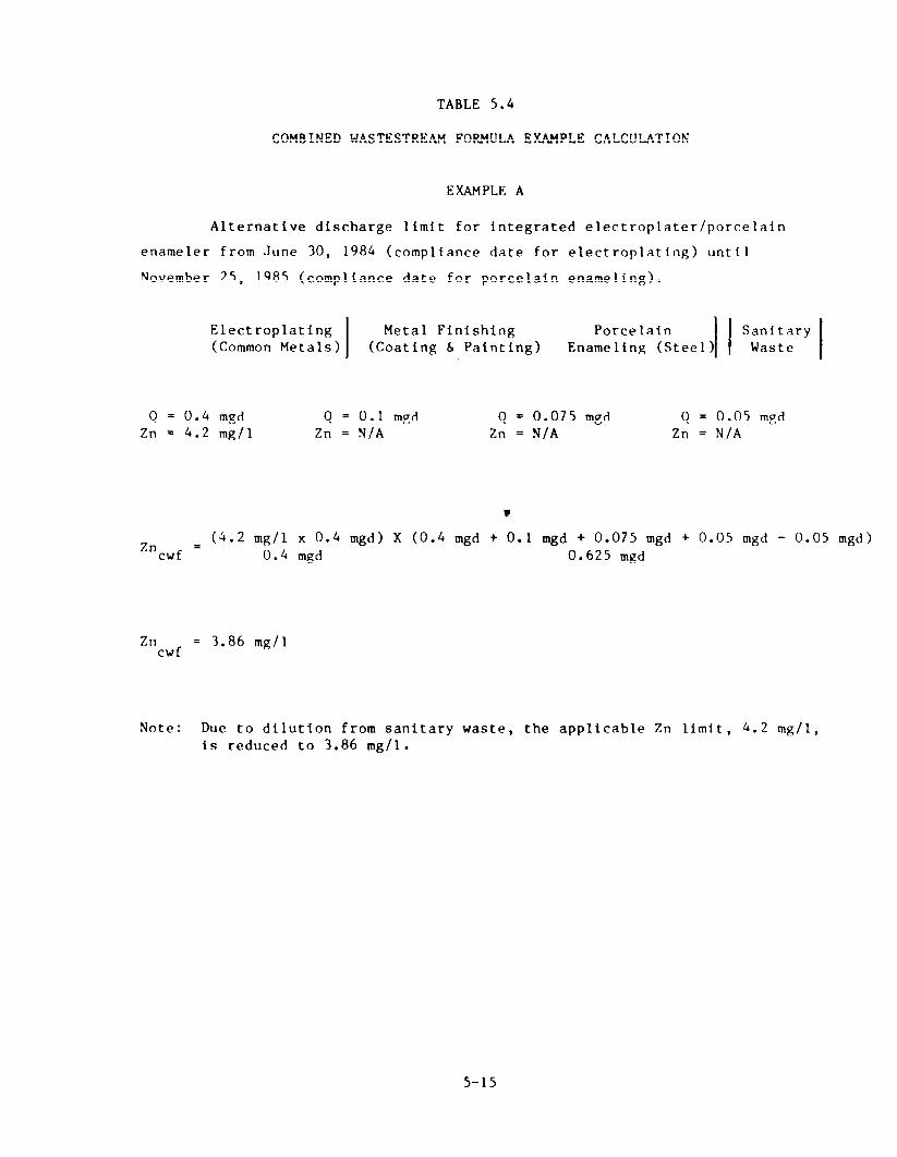
TABLE 5.4
COMBINED WASTESTREAM FORMULA EXAMPLE CALCULATION
EXAMPLE A
Alternative discharge limit for integrated electroplater/porcelain
enameler from June 30, 1984 (compliance date for electroplating) until
November 25, 1985 (compliance date for porcelain enameling).
Electroplating
I
Metal Finishing (Common Metals) (Coating 6 Painting)
Q = 0.4 mgd Zn = 4.2 mg/l
Q = 0.1 mgd Zn = N/A
Q = 0.075 mgd Zn = N/A
Q = 0.05 mgd Zn = N/A
Zn cwf = (4.2 mg/l x 0.4 mgd) X (0.4 mgd + 0.1 mgd + 0.075 mgd + 0.05 mgd - 0.05 mgd)
0.4 mgd 0.625 mgd
Zn cwf
= 3.86 mg/l
Note: Due to dilution from sanitary waste, the applicable Zn limit, 4.2 mg/l, is reduced to 3.86 mg/l.
5-15

TABLE 5.4 (Continued)
eMBINED WASTESTREAM FOBMlJ~A EXAMPLE CALCULATION
EXAMPL3 B
Alternative discharge limit for integrated electroplater/porcelain
enameler from November 25, 1985 until February 15, 1986 (compliance date for
metal finishing)
I Electroplating
I
Metal Finishing (Common Metals) (Coating 6 Painting) E,a~~~~~~a~~teel )I I”;~~:~ry 1
Q = 0.4 mgd Q = 0.1 mgd Zn = 4.2 mg/l Zn = N/A
Q = 0.075 mgd Zn = 1.33 mg/l
Q = 0.05 mgd Zn = N/A
.
Zn = cwf
4.2 mg/l (0.4 mgd) + 1.33 mg/l (0.075 mgd) x (0.4 mgd + 0.075 mgd)
(0.4 mgd + 0.1 mgd + 0.075 mgd + 0.05 mgd - 0.05 mgd) 0.625 mgd
Zn cwf
= 3.45 mg/l
Note : Alternate discharge limit is based on Electroplating and Porcelain Enameling categorical standards and proportioned by the flow of the regulated electroplating and porcelain enameling wastestreams. Due to dtlution from sanitary waste, the ,rlternate discharge limit is reduced.
5-16
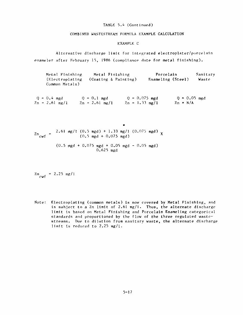
TABLE 5.4 (Continued)
COMBINED WASTESTREAM FORMULA EXAMPLE CALCULATION
EXAMPLE c
Alternative discharge limit for integrated electroplater/porcclaln
enameler after February 15, 1986 (compliance date for metal finishing).
Metal Finishing Metal Finishing Porcelain Sanitary (Electroplating (Coating d Painting) Enameling (Steel) Waste Common Metals)
Q = 0.4 mgd Q = 0.1 mgd Q = 0.075 mgd Q = 0.05 mgd Zn = 2.61 mg/l Zn = 2.61 mgll Zn = 1.33 mg/L Zn = N/A
.
Zn = cwf
2.61 mg/l (0.5 mgd) + 1.33 mg/l (0.075 mgd) x (0.5 mgd + 0.075 mgd)
(0.5 mgd + 0.075 mgd + 0.05 mgd - 0.05 mgd) 0.625 mgd
Zn cwf
= 2.25 mg/l
Note: Electroplating (common metals) is now covered by Metal Finishing, and is subject to a Zn limit of 2.61 mg/l. Thus, the alternate discharge limit is based on Metal Finishing and Porcelain Enameling categorical standards and proportioned by the flow of the three regulated waste- streams. Due to dilution from sanitary waste, the alternate discharge ltmit is reduced to 2.25 mgll.
5-17

TABLE 5.4 (Cant i nued >
CO?lBINED WASTESTREAM FORVIlLA EXAMPLE CALCULATION
Copper Forming and several other categorical standards arc expressed as
production-based limits. The example be‘ow converts production-based limits
to equtvnlent concentration-based limits. These equivalent concentration-
based limits can then be used as the standard for Copper Forming.
Copper Forming (Solution Heat Treatment) = 0.943 mg/of f-kg of copper heat Maximum Daily Limit for Zinc treated
Average Daily Production During = 30,000 off-kg of copper heat Last 12 months treated per day
Average Daily Water Usage in Solrrtion Heating Treating Drlring Last 12 months
Step 1: Convert Product Ion-based Limit to Equivalent Concentration Limit
Concent rat f on = (Production-Based Lirnit)(Avg. Daily Production Rate; Equivalent (Avg. Daily Flow from Regulated Process) (Conversion Factor)
Z”(equtvalent) = 0.943 mg/off-kg (30,000 off-kg/day)
400,000 gpd (3.785 liters/gallon) = 0.019 mg/l
Step 2: Once the concentration-based eqlrivalent Is determined, then the
alternate limtt can be calculated as in Example A.
Copper Forming Yetal Finish ;ng Porcelain Sanitary (Soln t ion Heat (Coating 6 Patnting) Enameling (Steel > Wnstc
Treatment >
Q = 0.4 mgd Q = 0.1 mgd Q = 0.075 mgd Q = 0.05 mgd Zn = 0.019 mg/l Zn = 2.61 Zn = 1.33 Zn = N/A
t
Zn = cwf
(0.019 mg/l x 0.4 mgd) + (2.61 mg/l x 0.1 mgd) + (1.33 mg/l x 0.075 mgd) X (0.4 mgd + 0.1 mgd + 0.075 mgd)
(0.4 mgd + 0.1 mgd + 0.075 mgd + 0.05 mgd - 0.05 mgd) 0.625 mgd
Zn cwf
= 0.59 mg/l
Note : Off-kg shall mean the mass of copper ore copper alloy removed from a for-mink: or ancillary operation at the end of a process cycle for transfer to a different machine or process.
5-1:3

TABLE 5.4 (Continued)
COMBINED WASTESTREAM FORMULA EXAMPLE CALCULATION
EXAMPLE E
For the several categorical standards shown in Example D, permit authori-
ties may wish to utilize mass limits. The example below converts concentra-
tion limtts to mass-based limits and utilizes the production-based limits (and
alternate limits).
Copper Forming
Copper Forming (Solution Heat Treatment) = 0.943 mg/off-kg of copper heat Maximum Daily Limit for Zinc treated
Average Daily Production During = 30,000 off-kg of copper heat Last 12 months treated per day
Average Daily Water Usage in Solution Heat Treating During Last 12 months
= 400,000 gpd
Allowable Zn Mass = 0.943 (30,000) = 28,290 mg
Metal Finishing
Metal Finishing Maximum Daily Limit for Ztnc
= 2.61 mg/l
Average Daily Productton During Last 12 months
= not required
Average Daily Water Usage in Metal Ftnishing
= 100,000 gpd
Allowable Zn Mass = 2.61 (100,000 x 3.78)= 986,580 mg
Porcelain Enameling
Porcelain Enameling (steel basis material) = (53.3 + 0.85) mg/m2 of area Maxtmum Daily Limit for Zinc processed or coated thru metal
preparation and coating operation, respectively.
Average Daily Production During
Last 12 months
= 5570 q 2 of preparation
7250 m2 of coating
5-19

TABLE 5.4 (Continued)
COMBINED WASTESTREAM FORMIJLA EXAMPLE CALCULATION
EXAMPLE E (Continued)
Average Daily Water Usage in Porcelain Enameling
= 75,000 gpd
Allowable Zn Yass = 53.3(5570>+0.85(7250)=303,044 mg
Copper Forming Metal Finishtng Porcelain Sanitary (Solution Heat (Coating 6 Painting) Enameling (Steel) Waste
Treatment)
Zn cwf
= 28,290 + 986,580 + 303,044
= 1,317,914 mg/day
Zn cwf
= 1.3 kg/day or (2.86 lbs/day)
5-20
grant removal credits in the June 26, 1978 General Pretreatment Regulations.
On January 28, 1981, the removal credits provision, as well as many other
portions of the pretreatment regulations, were amended. Under the 1981
provision, any POTW seeking removal credit authority was required to demon-
strate its removal performance by sampling its influent and effluent and
calculating its removal rates based on this data. Removal capability of each
POTW, therefore, was to be determined on a case-by-case basis. In addition to
the sampling requirements the provision specified the other prerequisites for
obtaining removal credit authority. Only the Approval Authority (either EPA
or the State) can grant removal credit authority to a POTW.
A revtsed removal credit regulation was proposed on September 28, 1982
(47 Fed. Reg. 42698). The final regulation on removal credits is due for
promulgation in March 1984. Until then, POTWs may apply for removal credit
authority under the existing procedures contained In Section 403.7 of the
January 28, 1981 General Pretreatment Regulations.
5.7 FUNDAMENTALLY DIFFERENT FACTORS VARIANCE
A request for a fundamentally different factors (FDF) variance is a
mechanism by which a Categorical Pretreatment Standard may be adjusted, making
it more or less stringent, on a case-by-case basis. If an indirect dis-
charger, a POTW, or any interested person believes that the factors relating
to a specific indirect discharger are fundamentally different from those
factors considered during development of the relevant categorical pretreatment
standard and that the existence of those factors justifies a different
discharge limit from that specified in the Categorical Standard, then they may
submit a request to EPA for such a variance (See 40 CFR 403.13).
This section was the subject of a recent court decision (U.S. Court of
Appeals for the Third Circuit) in September of 1983. The Court held that the
EPA lacks authority to issue variances to Indirect dischargers for toxic pol-
lutants. As a result of the Court’s decision, FDF variances can only be
granted for non-toxic pollutants. Since the electroplating and metal finish-
ing categorical standards contain limits only for toxics, no variance is
available for this industry.
5-2 1

5.8 LOCAL LIMITS
Local limits are numerical pollutant concentration or mass-based values
that are developed by a POTW for controlling the discharge of conventional,
non-conventional or toxic pollrltants Frcbm indirect sources. They differ from
National Catcxorical Pretreatment Standards in that Categorical Prrtrcatment
Standards art’ developed by EPA and are I)ascBd llpon the dcmonst rated performance
of avni lable pollutant control technologies (for specific categorical indus-
tries). These national technology-basclt categorical standards do not consider
local environmental criteria or conditions, and arc only developed to assure
that each industry vi thin a specified category meets a minimum discharge
standard which is consistent across the United States for a11 POTWs. Loca 1
limits, on the other hand, are developed to address specific localized impacts
on POTWs and their receiving waters. Lacal limitations are typically designed
to protect the POTW from:
0 The introduction of pollutants into the POTW which could interfere with its operation
l Pass-through of inadequately treated pollutants which could violate a POTW’s NPDES permit or applica’>le water quality standards
l The contamination of a POTW’s ;ludgc which would limit sludge uses or disposal practices.
Local limits, as the name implies, take into consideratton the factors
that are unique to a sperif ic POTW, whereas categorical pretreatment standards
are developed only for a general class of industrial dischargers. Local
limits are requtred under 40 CFR 403.5 and must be developed when it ts
determined that Categorical Pretreatment Standards are not sufficient to
enable the POTW to meet the above three Pretreatment Program objectives.
To assist municipalities in developing defensible and technically sound
numerical effluent limitations, EPA h.ls prepared some general guidelines on
limit development in its document “Guidance Manual for POTW Pretreatment
Program Development.” Appendix L of this document lists the general method-
OlORY 9 required formulas and typical environmental criteria used to develop
local limits. This manual is available from EPA Regional offices and NPDES
5-22

States and should be carefully followed when developing local limits. Al-
though a detailed discussion of local limit development is beyond the scope of
thts document, the general methodology includes the following four steps:
Step 1 - Determine the maximum headworks loading (for each specific pollutant) that will assure that the three fundamental oh.jec- tives of the pretreatment program are met.
step 2 - Calculate the allowable loading to the POTW by subtracting the uncontrollable portion of pollutant discharge to the POTW (from domestic, commercial and infiltration/inflow sources > from the total headwork loading value.
Step 3 - Distribute the controllable loading to industrial trscrs through an allocation process.
Step 4 - Derive specific local limits from the allocation results.
The above four step process must be performed for each pollutant which
the POTW determines may need a specific local limitation. As a general rule,
the limit setting analysis should be performed for all pollutants which are
discharged to the POTW in significant quantities. The POTW shou!d identify
pollutants of concern through an evaluation of the POTW’s industrial waste
survey. A procedure for evaluating industrtal waste survey results is
included in the EPA guidance manual mentioned earlier.
To assist POTWs with the development of local limits EPA has developed a
computer program that incorporates the general methodology required to develop
local limits and alleviates a substantial amount of the tedious calculations
required to develop these limits. This computer program has the following
capabilities to aid the POTW in limit development:
l Performs the four-step 1imLt setting analysis on microcomputer or mainframe
l Screens input data provided by the POTW
l Supplements POTW data with “built-in” files containing data on Industrial/Munfcipal wastewater characteristics, POTW removal rates, and PO’IW inhibition values
5-23

l Allocates controllable pollutant loads using several different methodologies
0 Compares calculated local limits to EPA Categorical Standards.
POTWs may obtain information on this computer program by contacting any of the
ten EPA Regional offices. Instructions will be provided on how to use the
comprlter program as well as how to acce:is a computer system which supports it.
5-24

REFERENCES
Electroplating Federal Register Notice
Final Regulations Promulgated Correction Notice (Typographical errors) Correction Notice (Delayed compliance for Integrated Facilities) Revision to 9/07/79 Promulgation of 7/03/80 Amended (Integrated Facilities Compliance) Amended (Added total toxic organic limit) Amended (Allows PSES compliance beyond 7/1/84) Correction/Clarification Notice (Compliance Dates)
Metal Finishing
Final Regulations Promulgated Amended (Allows PSES Compliance beyond 7/1/84 Correction/Clarification Notice (Compliance Dates) Correction Notice (Typographical Errors)
General Pretreatment Regulations
40 CFR Part 403, 46 FR 9404
Final Development Document - Electroplating
Final Development Document - Metal Finishing
Guidance Manual for POTW Pretreatment Program Development
Procedures Manual for Reviewing a POTW Pretreatment Program Submiss ion
August 1979
June 1983
October 1983
October 1983
09/07/79 44FR52618 10/01/79 44FR56330
03/25/80 45FR19246 01/28/81 40CFR9462 01/21/83 48FR2774 07/25/83 48FR32482 09/15/83 48FR41410
09126183 48FR43680
07/15/83 48FR32485 09/15/83 48FR41410
09/26/83 48FR43681 10/03/83 48FR45105
01/28/81
440/1-79/003
440/1-83/091
---
Copies of the technical and economic documents may be obtained from the National Technical Information Services, Springfield, VA. 22161 (703/487-4650). Pretreament Program Manuals may be obtained from U.S. EPA, Permits Division (EN-336), Washington, D.C. 20460
R-1