group maintenance - pump
TRANSCRIPT
8/8/2019 Group Maintenance - Pump
http://slidepdf.com/reader/full/group-maintenance-pump 1/22
[Type text] Page 1
Table of Contents
1.0 Introduction
2.0 Types of Pump
2.1. Positive-Displacement Pump
2.2. Dynamic Pump
2.3. Comparison between Centrifugal Pumps and Positive-Displacement
3.0 Basic Pump Component
3.1. Types of Impeller
3.1.1. Open Impelled
3.1.2. Closed Impelled
3.1.3. Comparison between Open and Closed Impeller
3.2. Mechanical Seal
4.0 Pump Terms
5.0 Standard of Design
6.0 Analysis
6.1. Hydraulic power 6.2. Specific Speed
6.3. Net Positive Suction Head
6.4. Reading a Pump Performance Curves
6.5. Pump Operating Range
7.0 General Installing Method
7.1. Installation of Pump, Motor and Base
7.2. General Piping Requirement
7.3. Suction Piping
7.4. Discharge Piping
7.5. Suction Head (Flooded Suction) Conditions
7.6. Suction Lift Conditions
8.0 General Precautions
9.0 Inspection of System
10.0 Troubleshooting
11.0 Pump Enquiry Information
Appendixes
Appendix A Types of Pump and Basic Components
Appendix B Service Liquid
Appendix C Pump Performance Curves
8/8/2019 Group Maintenance - Pump
http://slidepdf.com/reader/full/group-maintenance-pump 2/22
[Type text] Page 2
1.0 Introduction
Pump is the oldest f luid-energy-transf er device knows. For examples, the under-shot-bucket
waterwheels and Archimedes screw pump, still being manuf actured today to handle solid-liquid
mixtures. A pump displaces a volume by physical or mechanical action.
2.0 Types of Pump
There are two types of pump: positive-displacement and dynamic pumps
2.1. Positive-Displacement Pump
Positive-displacement pumps (PDPs) force the f luid along by volume changes. A cavity opens, and
the f luid is admitted through an inlet. The cavity then closes, and the f luid is squeezed through an
outlet. A brief classification of PDP designs is as follows:
y Reciprocating
o Piston pump
o Diaphragm pumpy Rotary motion
o Lobe pump
o Screw pump
o Helical screw pump
o Gear pump
y Big positive-displacement pump
All PDPs deliver a pulsating or periodic f low as the cavity volume opens, traps, and squeezes the
f luid. Their great advantage is the delivery of any f luid regardless of its viscosity. PDP can operate up
to very high pressures (300 atm) but typically produces low f low rates (100 gal/min).
PDPs are found in a wide range of applications of chemical-processing, liquid delivery, marine
biotechnology, and pharmaceutical as well as food, dairy and beverage processing.
2.2. Dynamic Pump
Dynamic pumps simply add momentum to the f luid by means of f ast-moving blades or vanes or
certain special designs. There is no closed volume. The f luid increase momentum while moving
through open passages and then converts its high velocity to a pressure increase by exiting into a
diffuser section. Dynamic pumps can be classified as follows:
y Rotary
o Centrifugal pump
o Axial f low pump
o Mixed f low pump
y Special designs
o Jet pump or ejector
o Electromagnetic pump for liquid metals
o Fluid-actuated for gas-lift or hydraulic-ram

8/8/2019 Group Maintenance - Pump
http://slidepdf.com/reader/full/group-maintenance-pump 3/22
[Type text] Page 3
Dynamic pumps generally provided a higher f low rate than PDPs and a much steadier discharge but
are ineff ective in handling high-viscosity liquids. Adynamic pump can provide very high f low rate (up
to 300.000 gal/min) but usually with moderate pressure rises (a f ew atmospheres).
Dynamic pumps are found is wide range of applications of irrigation, water supply, gasoline supply,
air conditioning system, refrigeration, chemical movement, sewage movement, f lood control and
marine services. Due to the wide variety, pumps have a diff erent shapes and sizes. This is based on
the usage industrial requirements.
*All the diff erent types of pump are shown in Appendix A.
2.3. C omparison betweenC entrifugal Pumps and Positive-Displacement Pumps
Parameter Centrifugal pumps PDPs
Optimum f low and pressure
application
y Medium/high capacity
y Low/medium pressure
y Low capacity
y High pressure
Maximum f low rate y 100,000+GPM y 100,000+GPM
Low f low rate capability y No y Yes
Maximum pressure y 6,000+PSI y 100,000+PSI
Requires relief valve y No y Yes
Smooth or pulsating f low y Smooth y Pulsating
Variable or constant f low y Variable y Constant
Self -priming y No y Yes
Space consideration y Requires less space y Requires more space
Costs
y Lower initial
y Lower maintenance
y Higher power
y Higher initial
y Higher maintenance
y Lower power
Fluid handling
y Suitable for a wide
range including clean,
clear, non-abrasivef luids to f luids with
abrasive, high-solid
content
y Not suitable for high
viscosity f luids
y Lower tolerance for
entrained gases
y Suitable for clean,
clear, non-abrasive
f luids.y Specially-fitted pumps
suitable for abrasive-
slurry service
y Suitable for high
viscosity f luids
y Higher tolerance for
entrained gases
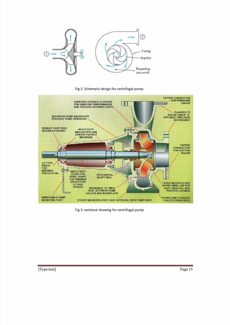
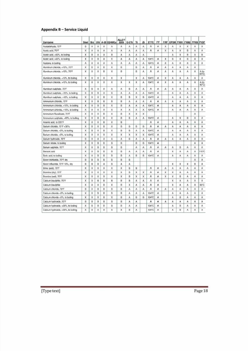
3.0 Basic Pump Component
There are two main components of a centrifugal pump which are the impeller and the volute/casing.
The impeller produces liquid velocity and the volute forces the liquid to discharge from the pump
converting velocity to pressure. This is accomplished by off setting the impeller in the volute and by
maintaining a close clearance between the impeller and the volute at the cut-water.
*The sectional drawing of a centrifugal pump and typical pump assembly are shown in Fig 3&4,
Appendix A.

8/8/2019 Group Maintenance - Pump
http://slidepdf.com/reader/full/group-maintenance-pump 4/22
[Type text] Page 4
3.1. T ypes of Impeller
Impeller is a rotating component. It is usually made of iron, steel, bronze, brass, aluminium or plastic
which transf er energy from the motor that drives the pump to the f luid being pumped by
accelerating the f luid outward from the center of rotation. Impeller usually is a short cylinder with an
open inlet (called eye) to accept incoming f luid. Then the f luid will be push by the vanes to drive-
shaft.
Impeller can be classified into open impeller and closed impeller. Both impellers are shown at Fig
5&6 from Appendix A.
3.1.1. O pen Impeller
y Fluid enters the eye of the impeller where the turning vanes add energy to the f luid
and direct it to the discharge nozzle. A close clearance between the vanes and the
pump volute, or the back plate in a f ew designs. This is to prevent most of the f luid
from recirculating back to the eye of the impeller.
3.1.2. C losed Impeller
y Fluid enters the eye of the impeller where the vanes add energy to the f luid and
direct it to the discharge nozzle. There is no impeller to volute or back plate
clearance to set
y Wear rings restrict the amount of discharge f luid that recirculates back to the
suction side of the impeller. When this wear ring clearance becomes excessive, the
wear ring must be replaced.
3.1.3. C
omparison betweenO pen and C
losed Impeller
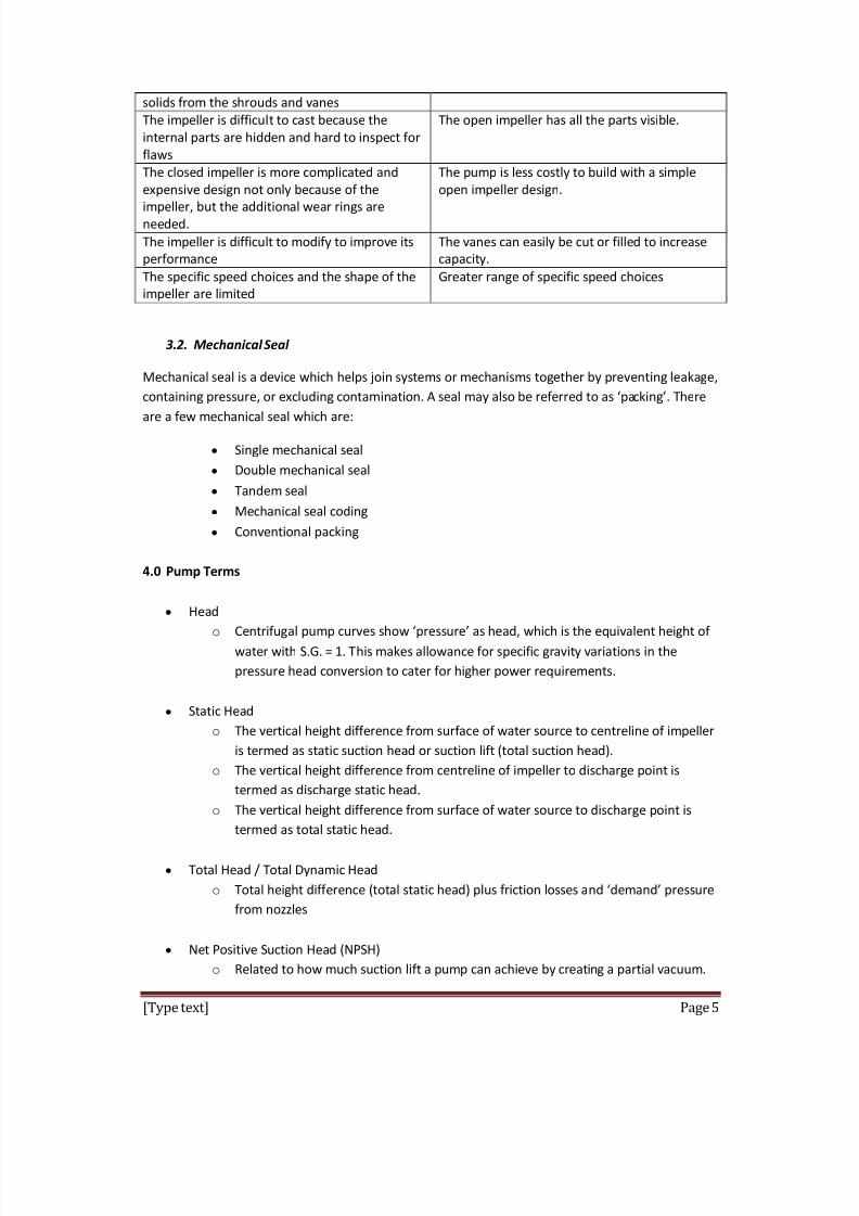
Closed impeller Open impeller
Can compensate for shaft thermal growth, but if
there is too much axial growth the vanes may
not line up exactly with the discharge nozzle
The impeller to volute or back plate clearance
must be ad justed when the pump is at operating
temperature and all axial thermal growth has
occurred.
Good for volatile and explosive f luids because
the close clearance wear rinds are the parts that
will contact if the shaft displaces from its
centreline.
Soft and non-sparking materials for impeller are
not very practical.
The impeller is initially very efficient, but loosesits efficiency as the wear ring clearance increases Efficiency can be maintained through impeller clearance ad justment.
No impeller ad justment is possible. Once the
wear rings clearances doubles they have to be
replaced. This means the pump had to be
disassembled just to check the status of the wear
rings
The impeller can be ad justed to compensate for
wear and stay close to its best efficiency. No
pump disassembly is necessary
The impeller can clog if the pump solids or
stringy material. It is difficult to clean out these
The open impeller is less likely to clog with
solids, but if it does, it is easy to clean
8/8/2019 Group Maintenance - Pump
http://slidepdf.com/reader/full/group-maintenance-pump 5/22
[Type text] Page 5
solids from the shrouds and vanes
The impeller is difficult to cast because the
internal parts are hidden and hard to inspect for
f laws
The open impeller has all the parts visible.
The closed impeller is more complicated and
expensive design not only because of the
impeller, but the additional wear rings areneeded.
The pump is less costly to build with a simple
open impeller design.
The impeller is difficult to modif y to improve its
performance
The vanes can easily be cut or filled to increase
capacity.
The specific speed choices and the shape of the
impeller are limited
Greater range of specific speed choices
3.2. Mechanical Seal
Mechanical seal is a device which helps join systems or mechanisms together by preventing leakage,
containing pressure, or excluding contamination. A seal may also be ref erred to as packing. There
are a f ew mechanical seal which are:
y Single mechanical seal
y Double mechanical seal
y Tandem seal
y Mechanical seal coding
y Conventional packing
4.0 Pump Terms
y Head
o Centrifugal pump curves show pressure as head, which is the equivalent height of
water with S.G. = 1. This makes allowance for specific gravity variations in the
pressure head conversion to cater for higher power requirements.
y Static Head
o The vertical height diff erence from surf ace of water source to centreline of impeller
is termed as static suction head or suction lift (total suction head).
o The vertical height diff erence from centreline of impeller to discharge point is
termed as discharge static head.
o The vertical height diff erence from surf ace of water source to discharge point is
termed as total static head.
y Total Head / Total Dynamic Head
o Total height diff erence (total static head) plus friction losses and demand pressure
from nozzles
y Net Positive Suction Head (NPSH)
o Related to how much suction lift a pump can achieve by creating a partial vacuum.
8/8/2019 Group Maintenance - Pump
http://slidepdf.com/reader/full/group-maintenance-pump 6/22
[Type text] Page 6
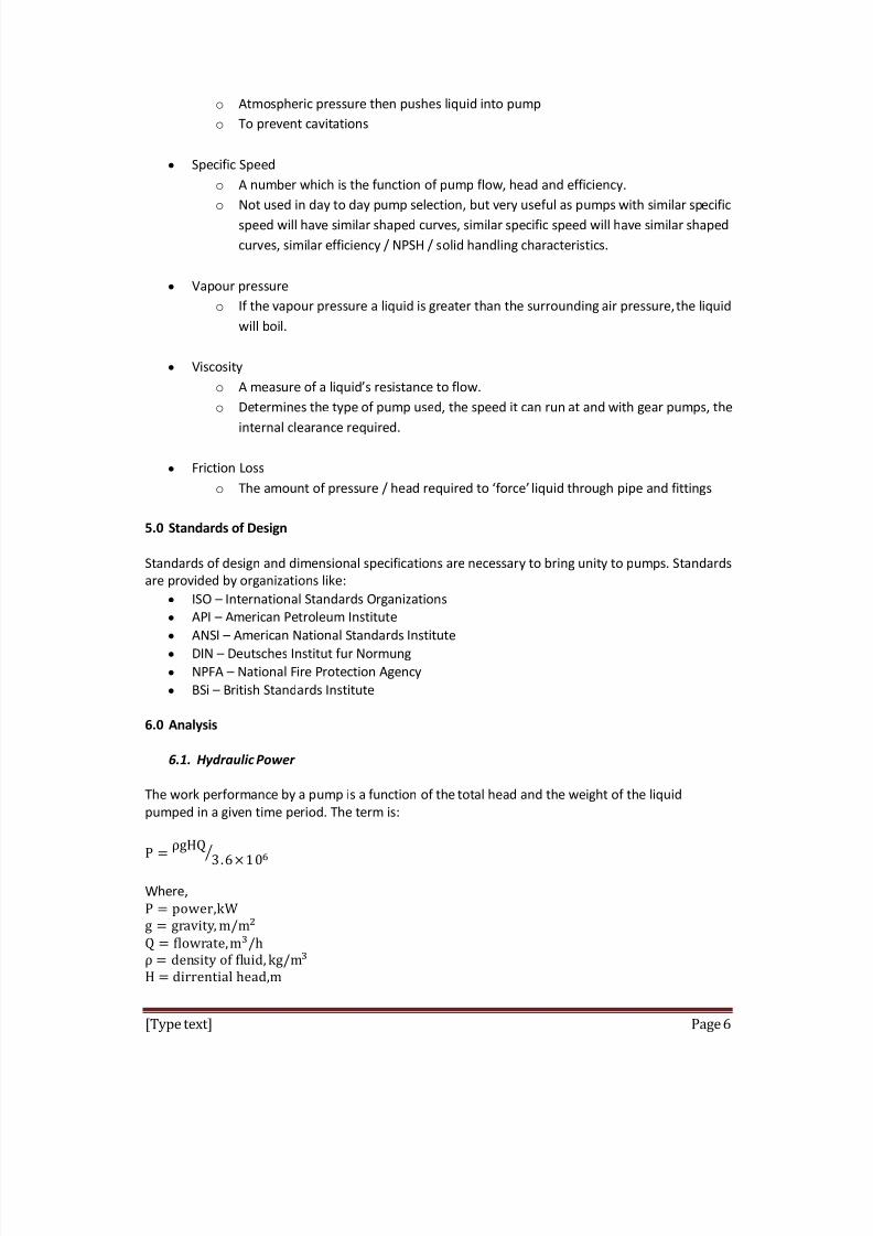
o Atmospheric pressure then pushes liquid into pump
o To prevent cavitations
y Specific Speed
o A number which is the function of pump f low, head and efficiency.
o Not used in day to day pump selection, but very useful as pumps with similar specific speed will have similar shaped curves, similar specific speed will have similar shaped
curves, similar efficiency / NPSH / solid handling characteristics.
y Vapour pressure
o If the vapour pressure a liquid is greater than the surrounding air pressure,the liquid
will boil.
y Viscosity
o A measure of a liquids resistance to f low.
o Determines the type of pump used, the speed it can run at and with gear pumps, the
internal clearance required.
y Friction Loss
o The amount of pressure / head required to force liquid through pipe and fittings
5.0 Standards of Design
Standards of design and dimensional specifications are necessary to bring unity to pumps. Standards
are provided by organizations like:
y ISO International Standards Organizations
y API American Petroleum Institute
y ANSI American National Standards Institutey DIN Deutsches Institut fur Normung
y NPFA National Fire Protection Agency
y BSi British Standards Institute
6.0 Analysis
6.1. H ydraulic Power
The work performance by a pump is a function of the total head and the weight of the liquid
pumped in a given time period. The term is:
Where,
8/8/2019 Group Maintenance - Pump
http://slidepdf.com/reader/full/group-maintenance-pump 7/22
[Type text] Page 7
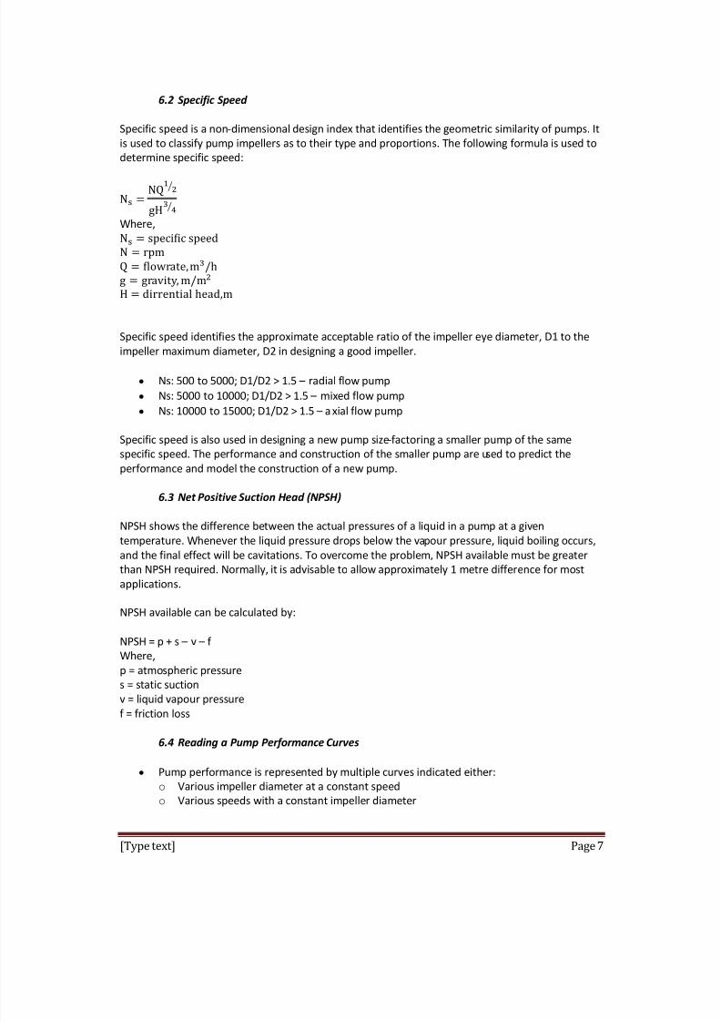
6.2 Specific Speed
Specific speed is a non-dimensional design index that identifies the geometric similarity of pumps. It
is used to classif y pump impellers as to their type and proportions. The following formula is used to
determine specific speed:
Where,
Specific speed identifies the approximate acceptable ratio of the impeller eye diameter, D1 to the
impeller maximum diameter, D2 in designing a good impeller.
y Ns: 500 to 5000; D1/D2 > 1.5 radial f low pump
y Ns: 5000 to 10000; D1/D2 > 1.5 mixed f low pump
y Ns: 10000 to 15000; D1/D2 > 1.5 axial f low pump
Specific speed is also used in designing a new pump size-f actoring a smaller pump of the same
specific speed. The performance and construction of the smaller pump are used to predict the
performance and model the construction of a new pump.
6.3 N et Positive Suction H ead ( N PSH)
NPSH shows the diff erence between the actual pressures of a liquid in a pump at a given temperature. Whenever the liquid pressure drops below the vapour pressure, liquid boiling occurs,
and the final eff ect will be cavitations. To overcome the problem, NPSH available must be greater
than NPSH required. Normally, it is advisable to allow approximately 1 metre diff erence for most
applications.
NPSH available can be calculated by:
NPSH = p + s v f
Where,
p = atmospheric pressure
s = static suction
v = liquid vapour pressuref = friction loss
6.4 Reading a Pump Performance C urves
y Pump performance is represented by multiple curves indicated either:
o Various impeller diameter at a constant speed
o Various speeds with a constant impeller diameter
8/8/2019 Group Maintenance - Pump
http://slidepdf.com/reader/full/group-maintenance-pump 8/22
[Type text] Page 8
y The curve consists of a line starting at shut-off . The line continues to the right, with head
reducing and f low increasing until the end of curve is reached
y Flow and head are linked, the relationship between them is locked until wear or blockage
changes the pump characteristics.
y Ref er to Appendix C for sample curve showing.
o Three performance curves ( various impellers or speed)
o Curves showing power absorbed by pump (read power at operating point, at point 1)
o Best efficiency point (BEP)
o Recommended operating range
o NPSH required
y Power absorbed by the pump is at point where power curve intersects pump curve at
operating point.
o Select motor or engine to suit specific engine speed or operating range cost eff ective
method where operating condition will not vary greatly
o Read power at end of curve most common way that ensures adequate power at
most operating conditions
o Read power at operating point plus 10%
o By using system curves all operating conditions can be considered best method where filling a long pipelines, large variations in static head
6.5 Pump O perating Range
y BEP is not only the operating point of highest efficiency but also the point where velocity
and therefore pressure is equal around the impeller and volute. As operating point moves
away from the BEP, the velocity change, which changes the pressure acting on one side of
the impeller.
y Outside the recommended operating range will damage the pump due to excess velocity
and turbulence. The resulting vortexes can create cavitations damage capable of destroying
the pump casing, back plate, and impeller in a shortperiod.
y When selecting or specif ying a pump, it is important not to add saf ety margins or baseselection on inaccurate information. The actual system cure may cross the pump curve
outside the recommended operating range.
y The best practice is to confirm the actual operating of the pump during operation to allow
ad justment to ensure correct operation and long service lif e.
7.0 General Installing Method
7 .1. Installation of Pump, Motor and Base
o The foundation area must be firm and level for maintaining pump alignment.
o The pump and motor assembly must be securely f astened to the base, and the basemust be securely attached to the foundation.
o The pump inlet should be as close to the liquid source as practical and pref erably
below it.
o The pump and motor shouldbe accessible for servicing and inspection.
o The pump and motor should be cleaned periodically to prevent the build-up of dust.
o If the pump was delivered as a complete long-coupled assembly, it was properly
aligned at the f actory. However, alignment should be checked after installation to
ensure that the pump and motor are still aligned. Alignment can be checked by

8/8/2019 Group Maintenance - Pump
http://slidepdf.com/reader/full/group-maintenance-pump 9/22
[Type text] Page 9
measurements at the coupling. Flexible couplings are not intended to compensate
for misalignment. Therefore, both angularity and parallelism should be checked and
corrected. If these are off by more than 0.015, the assembly should be realigned.
7 .2 General Piping Requirements
o All piping must be supported independently and must line up naturally with pumpports.
o DO NOT make final connection of piping to pump until the grout has hardened and
the pump and motor hold-down bolts have been tightened.
o Piping runs should be designed to minimize friction losses.
o Suction and discharge piping should be the same size or larger than the inlet and
outlet ports.
o Piping that handles both hot and cold liquids require proper installation of expansion
loops and joints so that thermal expansion of the piping will not cause misalignment.
o The piping should be arranged to allow the pump to be f lushed and drained prior to
the removal of the pump for servicing. Valves and unions should be installed to
allow the pump to be isolated during maintenance.
o
The piping system should be thoroughly cleaned prior to installation of the pump.o Gasket installation and materials must be suitable for the service.
7 .3 Suction Piping
o Properly installed suction piping is a necessity for trouble free pump operation. The
suction piping should be f lushed BEFORE connecting it to the pump.
o Use of elbows close to the pump suction port should be avoided. There should be a
minimum of five pipe diameters of straight pipe between the elbow and the suction
inlet. Any elbows used should be long radius.
o The suction pipe should be one or two sizes larger than the pump suction size, with
a reducer at the suction port. The diameter of the suction piping must never be
smaller than the pump suction port diameter.o Reducers, if used, should be eccentric at the pump suction port.
o Suction strainers, when used, must have a net free area of at least three times the
suction pipe area.
o Separate suction lines are recommended when more than one pump is operated
from the same supply.
7 .4 Discharge Piping
o Isolation valves should be installed in the discharge line. An isolation valve is
required for priming and regulating f low, and for isolating the pump for inspection
and maintenance.
o If quick closing valves are installed in the system, cushioning devices should be used
to protect the pump from surges and water hammer.
7 .5 Suction H ead (Flooded Suction ) C onditions o An isolation valve should be installed in the suction line to permit closing of the line
for pump inspection and maintenance.
o Piping should be level or slope gradually downward from the source of the supply.

8/8/2019 Group Maintenance - Pump
http://slidepdf.com/reader/full/group-maintenance-pump 10/22
[Type text] Page 10
o The suction pipe must be submerged sufficiently below the liquid surf ace to prevent
vortices and air entrapment at the supply.
7 .0 Suction Lift C onditions
o The suction pipe must slope continuously upward towards pump suction to
eliminate air pockets.o All joints must be air tight.
o A means of priming the pump must be provided.
8.0 General Precautions
o Always lock out the power to the pump driver when performing maintenance on the
pump
o Always lock out the suction and discharge valves when performing maintenance on
the pump
o Never operate the pump without saf ety devices installed
o Never operate the pump with suction and/or discharge valves closed
o Never operate the pump out of its design specifications
o Never start the pump without making sure that the pump is primed o Never use heat to disassemble pump
o Inspect the entire system before start-up
o Monitor the system during operation and perform maintenance periodically or as
required by the application
o Decontaminate pump using procedures in accordance with f ederal, state, local and
company environmental regulations
o Before performing maintenance on the pump, check with appropriate personnel to
determine if skin, eye or lung protection is required and how best to f lush the pump
o When performing maintenance, pay special attention to all cautionary statements
given.
9.0 Inspection of System
o Pump Construction: The materials of construction of the pump must be compatible
with the f luid to be pumped.
o Pump Mounting: The pump must be securely f astened to the base and ground using
the basic installation procedures as outlined by the Hydraulic Institute.
o Alignment: Long-coupled pumps should be checked for proper alignment
o Piping Layout: Process piping procedures are extremely important and must be
performed in accordance with the Hydraulic Institute. As a minimum, inlet piping
must be equal to or larger in diameter than the pump inlet size. Twists and bends of
pump inlet piping should be kept to an absolute minimum. Ensure that adequate
NPSH is available for the pump to operate properly.o Valves: All suction and discharge valves must be open during start-up and operation
or damage or malfunction may result.
o Motor Enclosure: The motor enclosure must be suitable for the conditions of
service.
o Electrical Hook-up: The electrical connections to the motor should be performed by
a certified electrician. It is critical that the supply voltage match the motor
nameplate voltage or serious motor damage or fire can result.
8/8/2019 Group Maintenance - Pump
http://slidepdf.com/reader/full/group-maintenance-pump 11/22
[Type text] Page 11
o Priming & Direction of Rotation: Prime the pump and then brief ly jog the motor to
assure proper motor direction. Motor shaft direction must be counter-clockwise as
seen from the pump end
o Saf ety: Never operate pump without all saf ety devices installed.
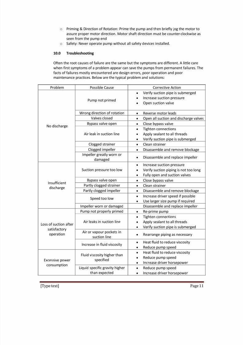
10.0 Troubleshooting
Often the root causes of f ailure are the same but the symptoms are diff erent. A little care
when first symptoms of a problem appear can save the pumps from permanent f ailures. The
f acts of f ailures mostly encountered are design errors, poor operation and poor
maintenance practices. Below are the typical problem and solutions:
Problem Possible Cause Corrective Action
No discharge
Pump notprimed
y Verif y suction pipe is submerged
y Increase suction pressure
y Open suction valve
Wrong direction of rotation y Reverse motor leads
Valves closed y Open all suction and discharge valvesBypass valve open y Close bypass valve
Air leak in suction line
y Tighten connections
y Apply sealant to all threads
y Verif y suction pipe is submerged
Clogged strainer y Clean strainer
Clogged impeller y Disassemble and remove blockage
Impeller greatly worn or
damaged y Disassemble and replace impeller
Insufficient
discharge
Suction pressure too low
y Increase suction pressure
y Verif y suction piping is not too long
y Fully open and suction valvesBypass valve open y Close bypass valve
Partly clogged strainer y Clean strainer
Partly clogged impeller y Disassemble and remove blockage
Speed too low y Increase driver speed if possible
y Use larger size pump if required
Impeller worn or damaged Disassemble and replace impeller
Loss of suction after
satisf actory
operation
Pump not properly primed y Re-prime pump
Air leaks in suction line
y Tighten connections
y Apply sealant to all threads
y Verif y suction pipe is submerged
Air or vapour pockets in
suction liney
Rearrange piping as necessary
Increase in f luid viscosityy Heat f luid to reduce viscosity
y Reduce pump speed
Excessive power
consumption
Fluid viscosity higher than
specified
y Heat f luid to reduce viscosity
y Reduce pump speed
y Increase driver horsepower
Liquid specific gravity higher
than expected
y Reduce pump speed
y Increase driver horsepower

8/8/2019 Group Maintenance - Pump
http://slidepdf.com/reader/full/group-maintenance-pump 12/22
[Type text] Page 12
Total head greater than
specified
y Increase pipe diameter
y Decrease pipe run
Total head lower than
specified, pumping higher
f low than expected
y Install throttle valve
Total head higher than rating
with f low at rating y Install impeller with correct diameter
Rotating parts binding or
severely worn y Disassemble and replace worn parts
Rapid pump wear
Abrasives in f luid
y Install suction strainer
y Limit solids concentration
y Reduce pump speed or use larger
pump running at lower speed
Corrosion wear
y Use materials of construction that
are acceptable for f luid being
pumped
Extended dry running y Install power sensor to stop pump
Discharge too high
y Increase pipe diameter
y Decrease pipe run
Excessive noise and
vibration
Partly clogged impeller
causing imbalancey Disassemble and remove blockage
Damaged impeller and/or
shaft
y Disassemble and replace damaged
parts
Base not rigid enough
y Tighten hold-down bolts on pump
and motor or ad just stilts
y Inspect grout and reground if
necessary
Worn pump bearings y Replace bearings
Worn motor bearings y Replace bearings or motor
Pump cavitations y Increase NPSH available
Excessive product
leakage
Static seal f ailure caused by
chemical incompatibility or
thermal breakdown
y Use O-ring or gaskets made of
material compatible with f luid and
temperature of the application
Static seal f ailure caused by
improper installation
y Install O-ring or gaskets without
twisting or bending
y Use star-pattern torque sequence
non house bolts during assembly
y Allow Tef lon O-ring to cold f low and
seat during tightening
y Torque bolts to specification
Pump port connections not properly sealed
y Use Tef lon tape or other suitable
sealant y Use gasket compatible with f luid and
temperature of the application
Crevice corrosion of pump
housing material
y Only pump chemicals that are
compatible with the pump housing
material
y Decrease temperature to reduce
corrosion rate to acceptable value
y Flush idle pumps that are used to
8/8/2019 Group Maintenance - Pump
http://slidepdf.com/reader/full/group-maintenance-pump 13/22
[Type text] Page 13
ump corrosive chemicals
y Eliminate contaminants in the f luid
that can accelerate corrosion wear
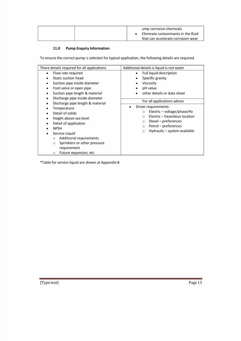
11.0 Pump Enquiry Information
To ensure the correct pump is selected for typical application, the following details are required.
There details required for all applications Additional details is liquid is not water
y Flow rate required
y Static suction head
y Suction pipe inside diameter
y Foot valve or open pipe
y Suction pipe length & material
y Discharge pipe inside diameter
y Discharge pipe length & material
y Temperature
y Detail of solids
y Height above sea level
y Detail of application
y NPSH
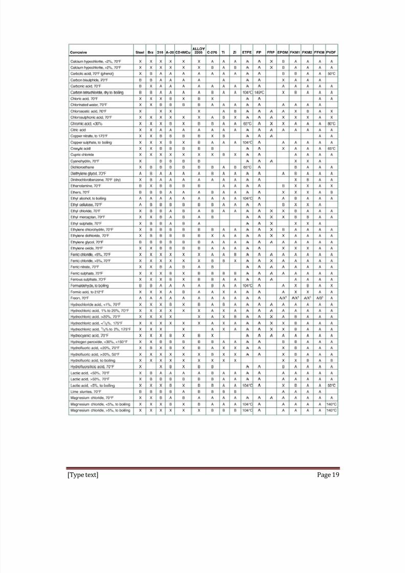
y Service Liquid
o Additional requirements
o Sprinklers or other pressure
requirement
o Future expansion, etc
y Full liquid description
y Specific gravity
y Viscosity
y pH value
y other details or data sheet
For all applications advise
y Driver requirements:
o Electric voltage/phase/Hz
o Electric hazardous location o Diesel pref erences
o Petrol pref erences
o Hydraulic system available
*Table for service liquid are shown at Appendix B

8/8/2019 Group Maintenance - Pump
http://slidepdf.com/reader/full/group-maintenance-pump 14/22
[Type text] Page 14
Appendix A Types of Pump and Basic Components
Fig 1: schematic design for PDP
a) Reciprocating piston pump
b) External gear pump
c) Double-screw pump
d) Sliding vane
e) Three-lobe pump
f)
Double circumf erential piston g) Flexible-tube squeegee
8/8/2019 Group Maintenance - Pump
http://slidepdf.com/reader/full/group-maintenance-pump 15/22

8/8/2019 Group Maintenance - Pump
http://slidepdf.com/reader/full/group-maintenance-pump 16/22
[Type text] Page 16
Fig 4: Typical pump assembly
Fig 5: Open impeller

8/8/2019 Group Maintenance - Pump
http://slidepdf.com/reader/full/group-maintenance-pump 17/22
[Type text] Page 17
Fig 6: Closed impeller
8/8/2019 Group Maintenance - Pump
http://slidepdf.com/reader/full/group-maintenance-pump 18/22
[Type text] Page 18
Appendix B Service Liquid
8/8/2019 Group Maintenance - Pump
http://slidepdf.com/reader/full/group-maintenance-pump 19/22
[Type text] Page 19

8/8/2019 Group Maintenance - Pump
http://slidepdf.com/reader/full/group-maintenance-pump 20/22
[Type text] Page 20

8/8/2019 Group Maintenance - Pump
http://slidepdf.com/reader/full/group-maintenance-pump 21/22
[Type text] Page 21

8/8/2019 Group Maintenance - Pump
http://slidepdf.com/reader/full/group-maintenance-pump 22/22