groundwater monitoring for epa prospective case … · groundwater monitoring for epa prospective...
TRANSCRIPT
National Energy Technology Laboratory
Daniel J. Soeder
Geologist-Hydrologist
Geology and Environmental Systems
30 July 2013
Groundwater Monitoring for EPA Prospective Case Study Site
• Drilling through shallow aquifers can affect groundwater
– Air infiltration into aquifer causing flow surge
– Drilling mud or chemicals getting into groundwater
• Hydraulic fracture pressure pulses can affect groundwater
– Pressure pulse reaches surface
– Can affect solubility of gas in groundwater
• Data needed on stray gas mobilization, fluid infiltration, water quality effects
– Wellbore integrity/reliability of casing and cement
– Surface spills of frac chemicals or produced water
– Soil gas migration, changes in composition
– Natural attenuation processes and rates.
Why Monitor Groundwater?
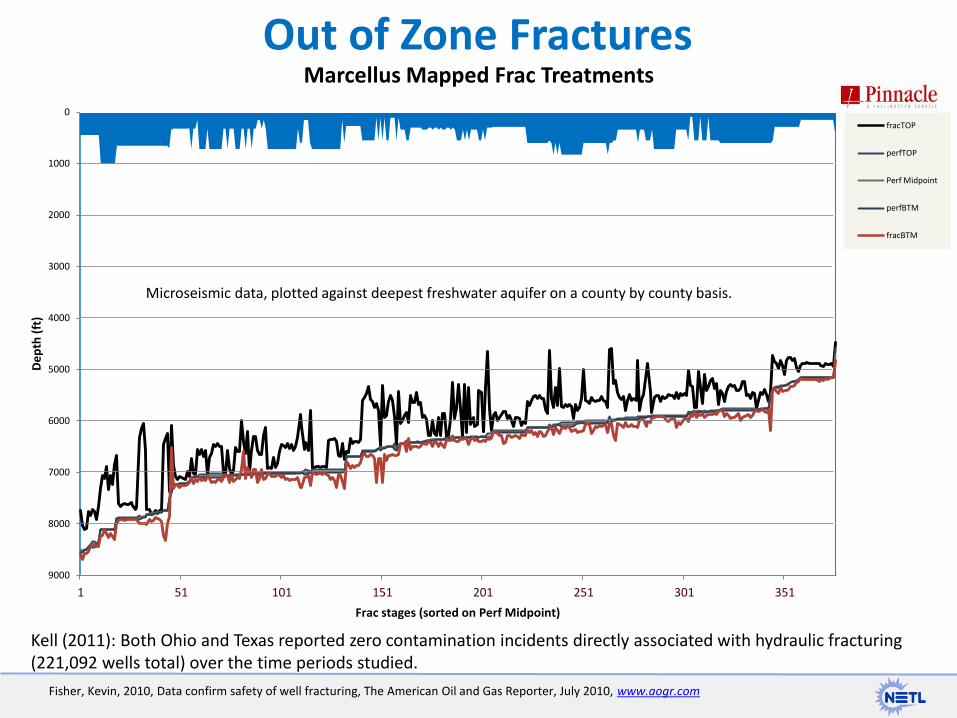
Out of Zone Fractures
Fisher, Kevin, 2010, Data confirm safety of well fracturing, The American Oil and Gas Reporter, July 2010, www.aogr.com
Kell (2011): Both Ohio and Texas reported zero contamination incidents directly associated with hydraulic fracturing (221,092 wells total) over the time periods studied.
0
1000
2000
3000
4000
5000
6000
7000
8000
9000
1 51 101 151 201 251 301 351
De
pth
(ft
)
Frac stages (sorted on Perf Midpoint)
Marcellus Mapped Frac Treatments
fracTOP
perfTOP
Perf Midpoint
perfBTM
fracBTM
Microseismic data, plotted against deepest freshwater aquifer on a county by county basis.
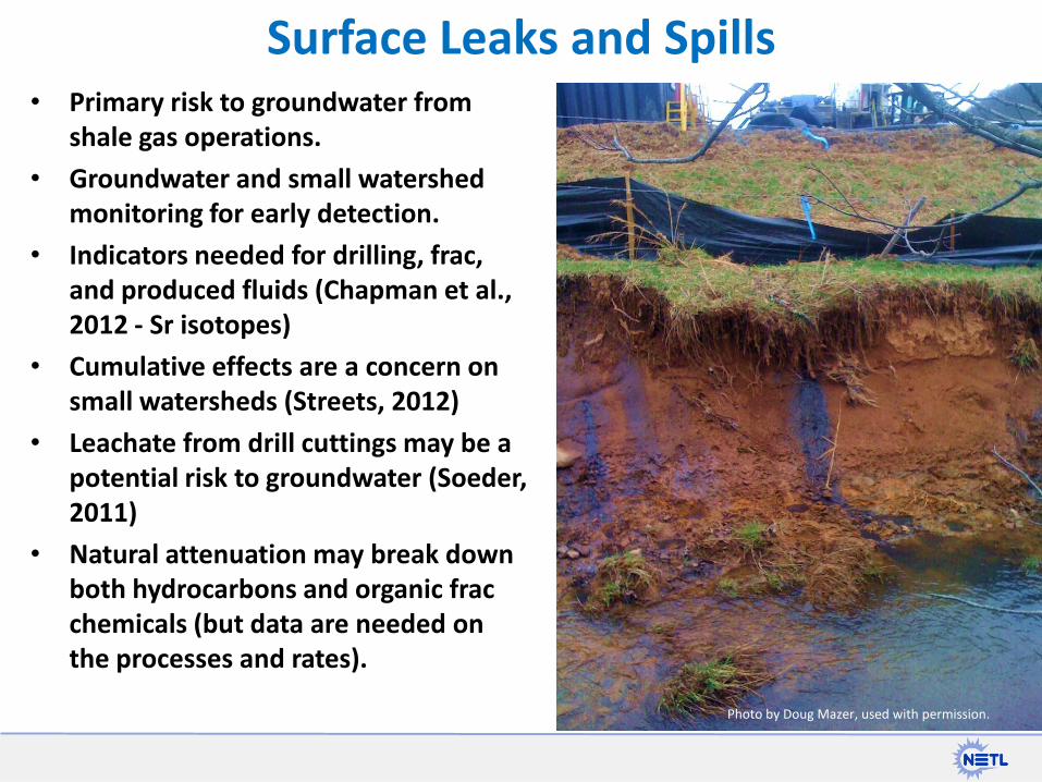
• Primary risk to groundwater from shale gas operations.
• Groundwater and small watershed monitoring for early detection.
• Indicators needed for drilling, frac, and produced fluids (Chapman et al., 2012 - Sr isotopes)
• Cumulative effects are a concern on small watersheds (Streets, 2012)
• Leachate from drill cuttings may be a potential risk to groundwater (Soeder, 2011)
• Natural attenuation may break down both hydrocarbons and organic frac chemicals (but data are needed on the processes and rates).
Surface Leaks and Spills
Photo by Doug Mazer, used with permission.
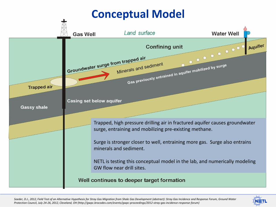
Trapped, high pressure drilling air in fractured aquifer causes groundwater surge, entraining and mobilizing pre-existing methane. Surge is stronger closer to well, entraining more gas. Surge also entrains minerals and sediment. NETL is testing this conceptual model in the lab, and numerically modeling GW flow near drill sites.
Conceptual Model
Soeder, D.J., 2012, Field Test of an Alternative Hypothesis for Stray Gas Migration from Shale Gas Development (abstract): Stray Gas Incidence and Response Forum, Ground Water Protection Council, July 24-26, 2012, Cleveland, OH (http://gwpc.brocodev.com/events/gwpc-proceedings/2012-stray-gas-incidence-response-forum)
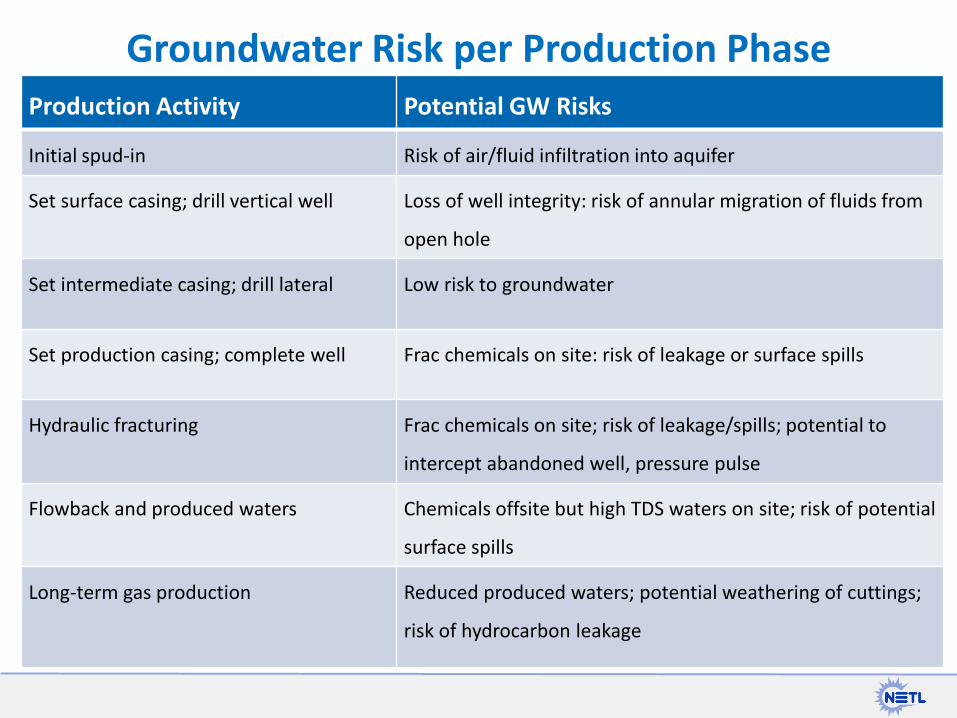
Groundwater Risk per Production Phase Production Activity Potential GW Risks
Initial spud-in Risk of air/fluid infiltration into aquifer
Set surface casing; drill vertical well Loss of well integrity: risk of annular migration of fluids from
open hole
Set intermediate casing; drill lateral Low risk to groundwater
Set production casing; complete well Frac chemicals on site: risk of leakage or surface spills
Hydraulic fracturing Frac chemicals on site; risk of leakage/spills; potential to
intercept abandoned well, pressure pulse
Flowback and produced waters Chemicals offsite but high TDS waters on site; risk of potential
surface spills
Long-term gas production Reduced produced waters; potential weathering of cuttings;
risk of hydrocarbon leakage
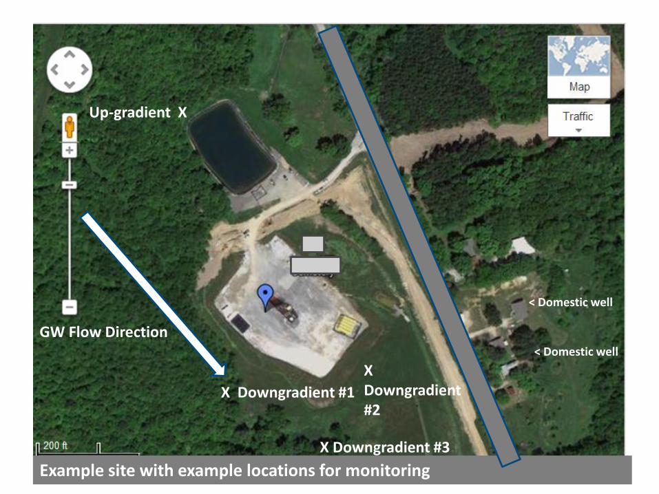
Example site with example locations for monitoring
Up-gradient X
X Downgradient #1
X Downgradient #3
< Domestic well
< Domestic well
X Downgradient #2
GW Flow Direction
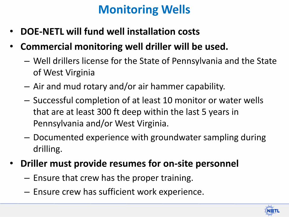
Monitoring Wells
• DOE-NETL will fund well installation costs
• Commercial monitoring well driller will be used.
– Well drillers license for the State of Pennsylvania and the State of West Virginia
– Air and mud rotary and/or air hammer capability.
– Successful completion of at least 10 monitor or water wells that are at least 300 ft deep within the last 5 years in Pennsylvania and/or West Virginia.
– Documented experience with groundwater sampling during drilling.
• Driller must provide resumes for on-site personnel
– Ensure that crew has the proper training.
– Ensure crew has sufficient work experience.
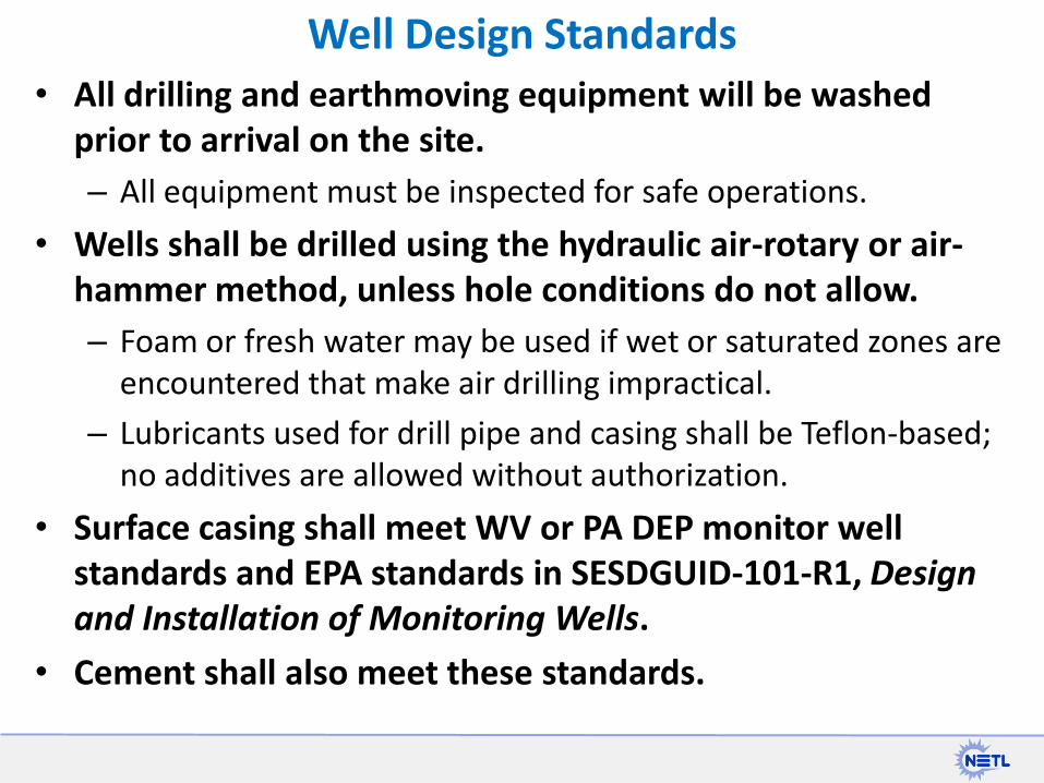
• All drilling and earthmoving equipment will be washed prior to arrival on the site.
– All equipment must be inspected for safe operations.
• Wells shall be drilled using the hydraulic air-rotary or air-hammer method, unless hole conditions do not allow.
– Foam or fresh water may be used if wet or saturated zones are encountered that make air drilling impractical.
– Lubricants used for drill pipe and casing shall be Teflon-based; no additives are allowed without authorization.
• Surface casing shall meet WV or PA DEP monitor well standards and EPA standards in SESDGUID-101-R1, Design and Installation of Monitoring Wells.
• Cement shall also meet these standards.
Well Design Standards
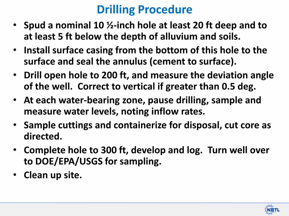
• Spud a nominal 10 ½-inch hole at least 20 ft deep and to at least 5 ft below the depth of alluvium and soils.
• Install surface casing from the bottom of this hole to the surface and seal the annulus (cement to surface).
• Drill open hole to 200 ft, and measure the deviation angle of the well. Correct to vertical if greater than 0.5 deg.
• At each water-bearing zone, pause drilling, sample and measure water levels, noting inflow rates.
• Sample cuttings and containerize for disposal, cut core as directed.
• Complete hole to 300 ft, develop and log. Turn well over to DOE/EPA/USGS for sampling.
• Clean up site.
Drilling Procedure
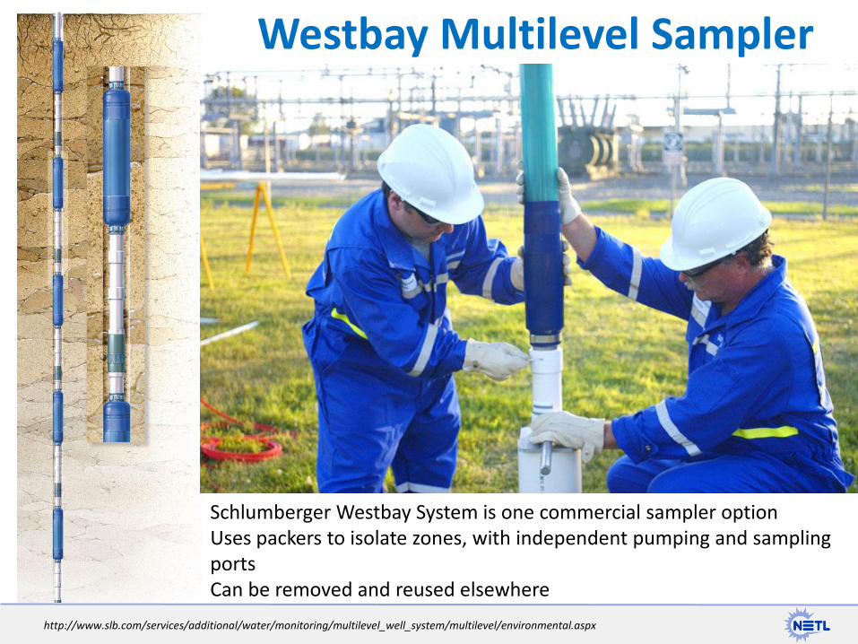
Westbay Multilevel Sampler
http://www.slb.com/services/additional/water/monitoring/multilevel_well_system/multilevel/environmental.aspx
Schlumberger Westbay System is one commercial sampler option Uses packers to isolate zones, with independent pumping and sampling ports Can be removed and reused elsewhere
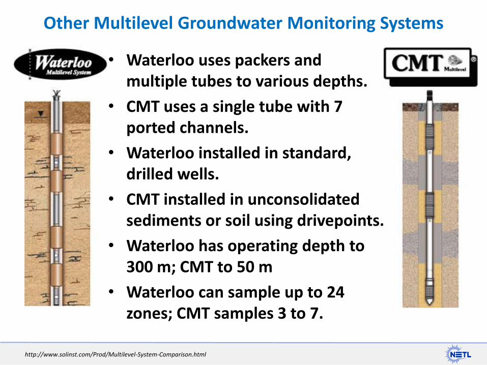
• Waterloo uses packers and multiple tubes to various depths.
• CMT uses a single tube with 7 ported channels.
• Waterloo installed in standard, drilled wells.
• CMT installed in unconsolidated sediments or soil using drivepoints.
• Waterloo has operating depth to 300 m; CMT to 50 m
• Waterloo can sample up to 24 zones; CMT samples 3 to 7.
Other Multilevel Groundwater Monitoring Systems
http://www.solinst.com/Prod/Multilevel-System-Comparison.html
• Use existing USGS monitoring well to field test Westbay System and others for pump and purge rates suitable for EPA groundwater sampling protocols.
• Identify industry cooperator and landowners who will allow groundwater monitoring wells to be placed in vicinity of shale gas well site (currently in discussions)
• DOE-EPA-USGS team will make joint decisions about well locations, depth, aquifer zones, & water sampling.
– Real-time monitor: level, pH, TDS, turbidity, DO, temp, gas
– Sample (minimum) pre-and post drilling, pre-and post frac
• DOE makes contacts with other shale gas drillers in other areas for similar access.
– Comparison studies on other shale plays.
Next Steps
DJS: Rev 7/24/2013