grooved inducer housing - ebaracryo.com · overview background npshr and why is it important for...
TRANSCRIPT

Improved Centrifugal Pump Performance with Counter Helical Inducer
Housing Grooves
Sarah D. Alison-Youel R&D Engineer
Ebara International Sparks, NV
AIChE Spring Meeting
March 22- 25, 2010 San Antonio, TX

Biography
Sarah received a Bachelor of Science degree in Mechanical Engineering with a minor in Mathematics from the University of Nevada, Reno in 2006. Since joining Ebara in 2007 she has been working with prototype engineering, taking a project from concept through to final testing. Currently Sarah is the Project Engineer for the first two-phase Tandem ExpanderTM, two of which have been installed in a Polish Oil and Gas LNG plant in Poland and for the Grooved Inducer Concept. Sarah has several research papers published in the American Institute of Chemical Engineers and the International Symposium on Transport Phenomena and Dynamics of Rotating Machinery conference proceedings. In addition, a research paper has been published in the International Journal of Rotating Machinery.
Overview
Background
◦ NPSHR and why is it important for pump performance
◦ NPSHR and inducer design
Grooved Inducer Housing Concept (patent pending)
Testing
◦ Grooved Inducer Housing Design
◦ Results
Future Work

Background NPSHR and Pump Design
NPSHR – Pump Performance
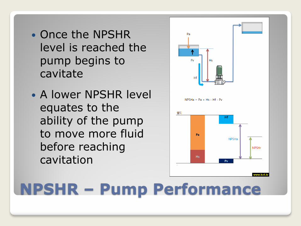
Once the NPSHR level is reached the pump begins to cavitate
A lower NPSHR level equates to the ability of the pump to move more fluid before reaching cavitation
NPSHR – Inducer Design
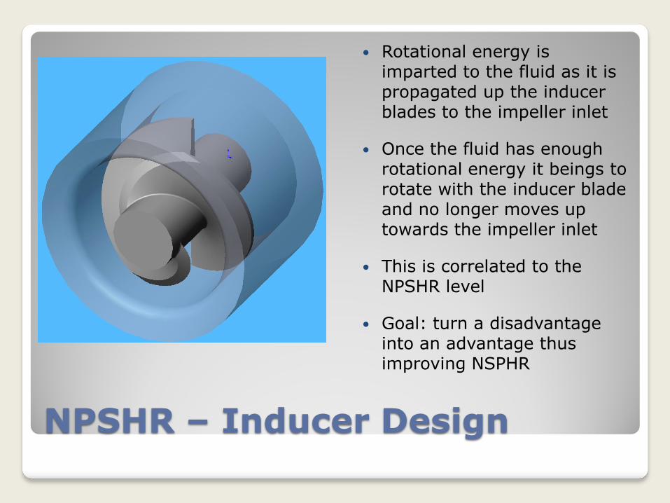
Rotational energy is imparted to the fluid as it is propagated up the inducer blades to the impeller inlet
Once the fluid has enough rotational energy it beings to rotate with the inducer blade and no longer moves up towards the impeller inlet
This is correlated to the NPSHR level
Goal: turn a disadvantage into an advantage thus improving NSPHR

Grooved Inducer Housing Concept Patent pending
Basic Concept
Use grooves or vanes on the inducer housing that are in a counter rotational direction to the inducer
These grooves or vanes will ‘catch’ the rotating fluid and the fluid will be pushed up in the grooves or along the vanes towards the impeller inlet
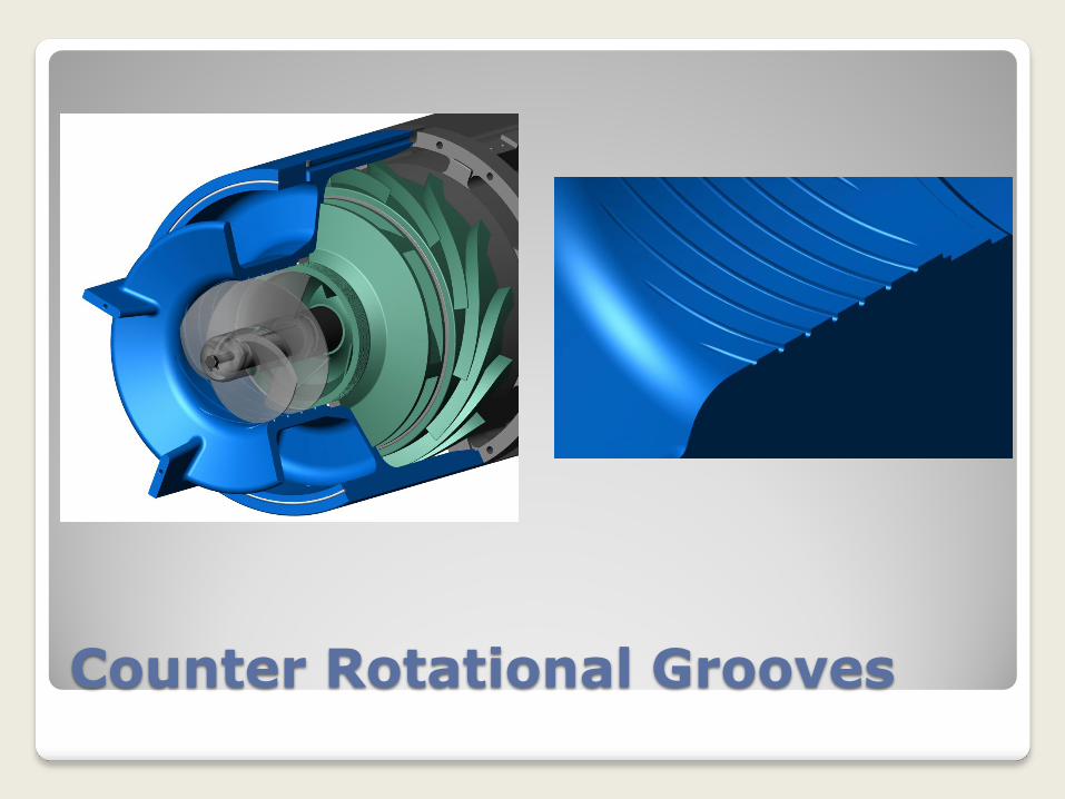
Counter Rotational Grooves
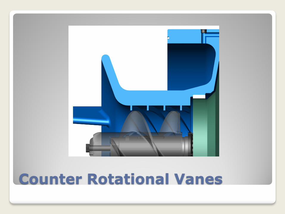
Counter Rotational Vanes

Testing Design, Results, Future Work
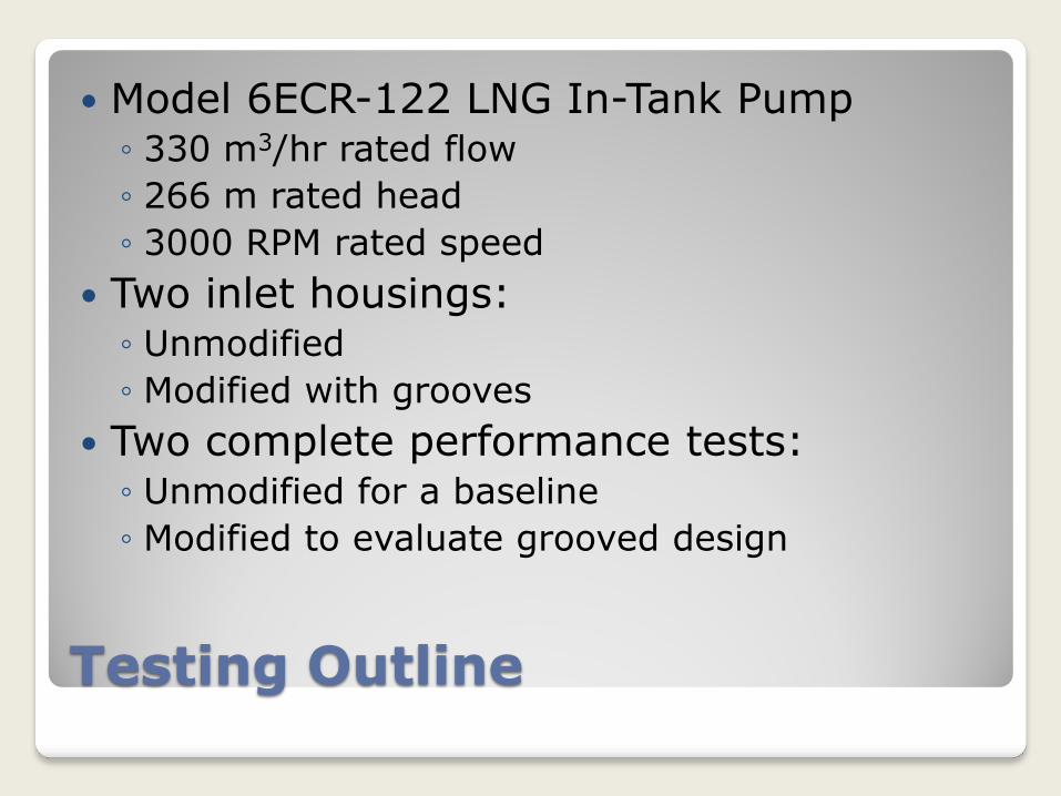
Testing Outline
Model 6ECR-122 LNG In-Tank Pump ◦ 330 m3/hr rated flow
◦ 266 m rated head
◦ 3000 RPM rated speed
Two inlet housings: ◦ Unmodified
◦ Modified with grooves
Two complete performance tests: ◦ Unmodified for a baseline
◦ Modified to evaluate grooved design
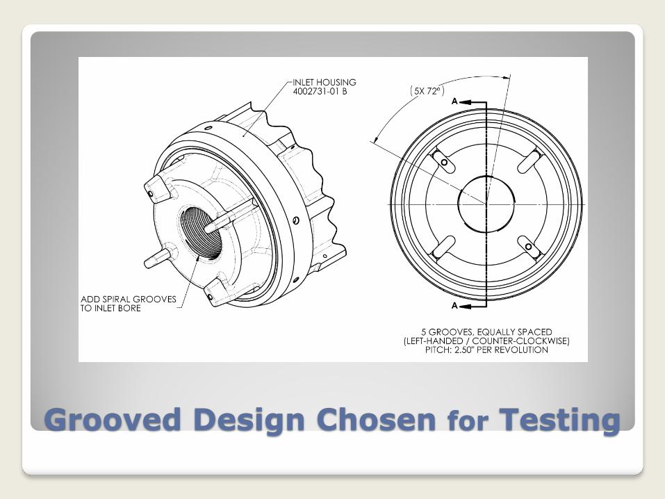
Grooved Design Chosen for Testing
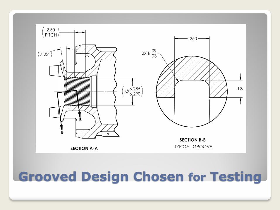
Grooved Design Chosen for Testing
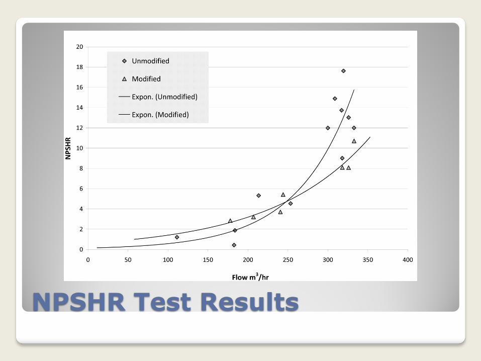
NPSHR Test Results
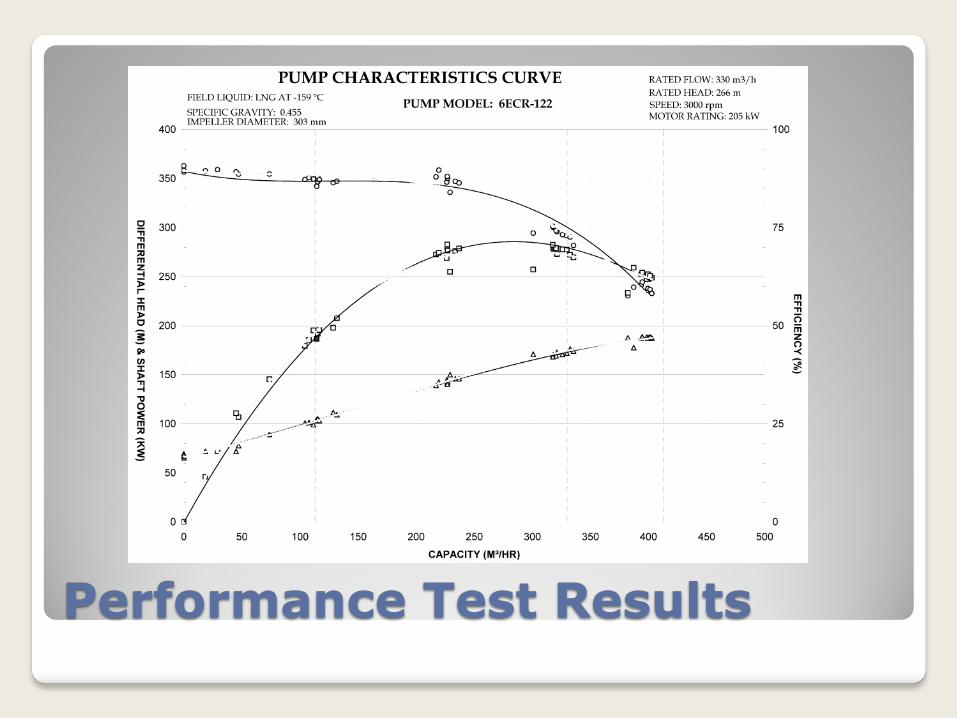
Performance Test Results
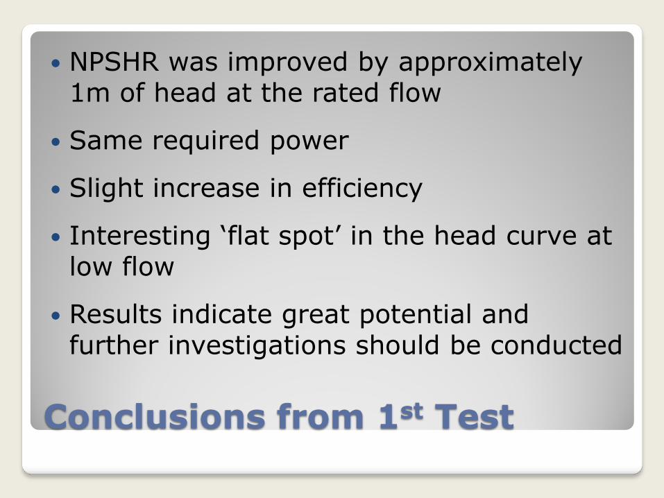
Conclusions from 1st Test
NPSHR was improved by approximately 1m of head at the rated flow
Same required power
Slight increase in efficiency
Interesting ‘flat spot’ in the head curve at low flow
Results indicate great potential and further investigations should be conducted
Future Work
CFD and further physical testing to investigate: ◦ Impact of the grooves on the head curve ◦ Study how variations may influence performance: Depth Width Pitch Number of grooves
◦ Application for larger head and flow pumps

Questions?