graphene–fe3o4 micro–nano scaled hybrid spheres: synthesis and synergistic electromagnetic...
TRANSCRIPT
Materials Research Bulletin 50 (2014) 285–291
Graphene–Fe3O4 micro–nano scaled hybrid spheres: Synthesis andsynergistic electromagnetic effect
Wei-dong Xue, Rui Zhao *, Xia Du, Fang-wen Xu, Meng Xu, Kai-xiang Wei
Institute of Applied Electrochemistry, Institute of Microelectronic & Solid State Electronic, University of Electronic Science and Technology of China, Chengdu
610054, PR China
A R T I C L E I N F O
Article history:
Received 25 June 2013
Received in revised form 22 October 2013
Accepted 9 November 2013
Available online 17 November 2013
Keywords:
A. Magnetic materials
A. Structural materials
D. Magnetic properties
A B S T R A C T
Graphene–Fe3O4 micro–nano scaled hybrid spheres with the diameter of �100 nm were fabricated via
solvent-thermal route, which combined the hybridization growth of Fe3O4 nanoparticles and graphene
oxide in one single step. The hybrid spheres showed a homogenous phase without obviously interfaces
between graphene and Fe3O4. Owing to the interfacial polarization and good separation of magnetic
properties, the interpenetrating constitution of the materials brought good synergistic effects on the
electromagnetic wave absorbing properties: a multi-frequency reflection band covered C-band and Ku-
band with maximum reflection loss �20 dB as the matching thickness of 5 mm gave very promising
desire for lightweight and strong electromagnetic attenuation applications.
� 2013 Elsevier Ltd. All rights reserved.
Contents lists available at ScienceDirect
Materials Research Bulletin
jo u rn al h om ep age: ww w.els evier .c o m/lo c ate /mat res b u
1. Introduction
Dense inorganic–organic hybrid materials offer opportunitiesfor creating unusual properties or combinations of properties [1].Magnetic property based on inorganic molecular and electronicconductivity originating from delocalized electron inorganic materials can be unified through formation of organic–inorganic assembly, a common phenomenon for devising multi-functional hybrids with numerous fascinating applications.
Magnetite (Fe3O4) nanoparticles (NPs) received intensiveinterest in recent years for its unique electric and magneticproperties due to the transfer of electrons between Fe2+ and Fe3+ inthe octahedral sites [2–4]. For a high performance in function-specific applications, magnetic particles must be spherical, havenarrow size distributions, a high magnetic saturation (ss) toprovide maximum signal, and a good dispersion in liquid media[5–7]. On the other hand, the physical properties of magneticmaterials exhibit a strong dependence on particle size, latticedefects or chemical stoichiometry [8–10]. In our previous work[11], we have synthesized mono-dispersed Fe3O4 microsphereswith diameters of 300 nm and had open pores on the shells, suchhierarchical microspheres exhibited good electromagnetic inter-ference shielding properties: two microwave magnetic loss peaks:one appears at 4.0–5.0 GHz, the other appears around 16.0–17.0 GHz, the magnetic loss peak in high frequency was believed
* Corresponding author. Tel.: +86 28 832 025 50; fax: +86 28 832 025 50.
E-mail address: [email protected] (R. Zhao).
0025-5408/$ – see front matter � 2013 Elsevier Ltd. All rights reserved.
http://dx.doi.org/10.1016/j.materresbull.2013.11.027
attributed to the effect of the morphology of the hierarchicalstructure.
Graphene, the so-called ‘‘thinnest material in our universe’’, asingle layer of sp2-bonded carbon atoms [12], has drawntremendous scientific interests for its extremely high mobilityand ballistic transport of electrons [13,14]. Many kinds ofgraphene-based materials have been fabricated for furtherextending their physicochemical properties and application areas,including chemical sensors [15], Li ion batteries [16], and field-effect transistors [17]. To date, electromagnetic (EM) waveabsorbing materials have attracted much attention owing tothe expanded EM interference problem. Carbon and its compositesare very promising EM absorbing materials [18,19]. As a new classof two-dimensional carbon nanostructure, graphene with a veryhigh surface area has shown excellent EMI properties [20,21],however, the carrier nobilities of graphene with a high qualityat room temperature are as high as 1000 cm2 V�1 s�1, whichis harmful to its EM absorption properties in terms of theimpedance match mechanism [22]. Also the EM interferenceproperties of materials exhibit strong dependence on particle size,morphology and chemical stoichiometry, which relied heavily onthe various synthesis methods. Thus, how to design and preparegood EM absorbing materials based on graphene still remains achallenge.
Here, we reported synthesis of graphene–Fe3O4 micro–nanoscaled hybrid spheres with the diameter of �100 nm via solvent-thermal route, which combined the hybridization growth of Fe3O4
NPs and graphene oxide in one single step. The graphene–Fe3O4
nano-scaled hybrid spheres showed a homogenous phase
W.- Xue et al. / Materials Research Bulletin 50 (2014) 285–291286
without obviously interfaces between graphene and Fe3O4. As self-assembling tendency could be the driving force to deviseheterogeneous materials layering the organic and inorganiccomponents alternately and the resultant hybrids exist likenano-composites with persistent individual properties. Thegraphene–Fe3O4 micro–nano scaled hybrid spheres in this workbrought excellent synergistic effects on the electromagnetic waveabsorbing properties: a multi-frequency reflection band covered C-band and Ku-band with maximum reflection loss �20 dB as thematching thickness of 5 mm gave very promising desire forlightweight and strong electromagnetic attenuation applications.Also from the calculation, we found that the observed microwaveabsorbing performance was not only from dielectric loss andmagnetic loss but also from geometrical effect. The multi-frequency reflection properties and geometrical effect of gra-phene–Fe3O4 hybrid material was very unique from the previouslyreports [20–22].
2. Experimental details
2.1. Preparation of graphene oxide
The procedure was as follows according to the reference [23]with minor modification: a 9:1 mixture of concentrated H2SO4/H3PO4 (360:40 ml) was added to a mixture of graphite flakes (3.0 g,1 wt equiv) and KMnO4 (18.0 g, 6 wt equiv), producing a slightexotherm to 30 8C. The reaction was cool to room temperature andkept vigorous stirring for 72 h, the colour of the reaction mixtureturned from dark green-black to purple red. Then the mixture waspoured into 600 ml deionized water very carefully, producinganother drastic exothermic reaction, after that 30% H2O2 (10 ml)was added to neutralize the overdosed KMnO4, the colour of thesolution turned from dark purple into light yellow, giving a stablegraphene oxide water colloid. The graphene oxide was isolated bycentrifugation, purified by washing repeatedly with deionizedwater, and vacuum dried at 60 8C for 24 h.
2.2. Preparation of graphene–Fe3O4 micro–nano scaled hybrid
spheres
Ultrasonic dispersed graphene oxide (0.0111 g) in ethylenegly-col (EG) (100 ml) and polyethylene 2000 (PEG 2000) (2.5 g)mixture at 80 8C to give a light yellow solution, then followed byaddition of FeCl3�6H2O (3.37 g) to form a brown mixture. The
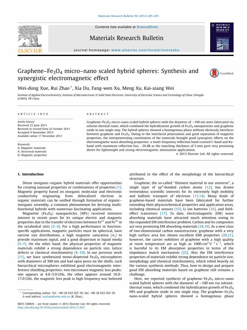
Fig. 1. Fabrication process for the graphene–Fe3O4 hybrid spheres: (a) stable suspensio
suspension; (c) graphene–Fe3O4 hybrid hydrogel prepared by solvent-thermal self-asse
sodium acetate trihydrate (NaAc) (9.0 g) was slowly added into thesolution and vigorous stirred for 2 h, the whole process was keptultrasonic to avoid the aggregation of the graphene oxide in EGagain. After that the brown mixture was sealed in a Teflon-linedstainless-steel autoclave, heated to and maintained at 200 8C for24 h, then allowed to cool to room temperature. The black productswere obtained by magnetic separation, washed several times withethanol and deionized water and dried at 80 8C overnight.
2.3. Characterization techniques
The synthesized products were characterized by X-ray diffrac-tion (XRD) (Rigaku RINT2400 with Cu Ka radiation), ScanningElectron Microscopy (SEM) (JSM, 6490LV) and TransmissionElectron Microscopy (TEM) (Hitach, H600). Magnetic study wasperformed by a vibrating sample magnetometer (VSM, RikenDenshi, BHV-525). Raman spectra were collected with RenishawINVIA Raman System (633 nm laser). The sample used forelectromagnetic measurements was prepared by homogeneouslymixing with wax in a mass ratio of 4:1. The complex permeabilitym (m0 = m � jm00) and permittivity e (e = e0 � je00) were measuredusing a vector network analyzer (Agilent 8720ET) at 1.0–18 GHz.
3. Results and discussion
The possible fabrication process for graphene–Fe3O4 hybridspheres was demonstrated in Fig. 1. Firstly, graphene oxide (GO)was slowly dissolved in the EG/PEG2000 mixture to form a stableand homogeneous light yellow solution (Fig. 1a). After FeCl3�6H2Oand NaAc added to the black solution sequent, a brown turbidsuspension gave the evidence of obtained FeOH(CH3COO)2
(Fig. 1b). Subsequently, these ternary components were solvent-thermal self-assembled at 200 8C for 24 h to form the graphene–Fe3O4 hybrid spheres (Fig. 1c). In this way, Fe3O4 NPs couldnucleate and aggregated to spherical morphology with simulta-neous incorporation of graphene oxide to give an interpenetratingnetwork structure.
The structure and morphology of as-prepared graphene oxideand graphene–Fe3O4 micro–nano scaled hybrid spheres wereinvestigated by means of SEM, TEM and XRD. From the SEM images(Fig. 3a) and TEM images (Fig. 4a) of the graphene oxide, thegraphene oxide used in our experiments showed a wrinkled andscrolled morphology, considering the graphene oxide so-called‘‘thinnest material in our universe’’, we sure about the successes in
n of graphene oxide solution; (b) graphene oxide/FeOH(CH3COO)2 in EG/PEG2000
mbly and its ideal assembled model.
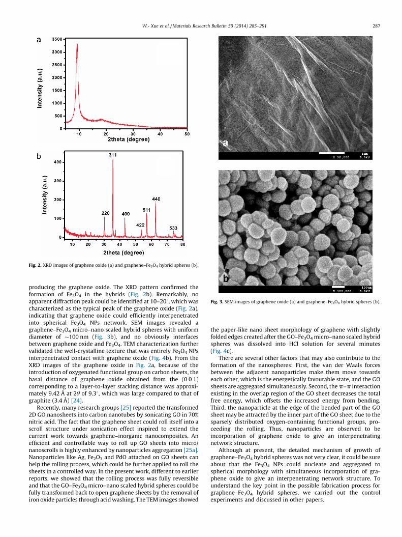
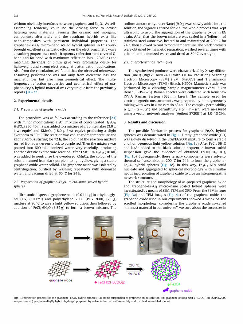
Fig. 2. XRD images of graphene oxide (a) and graphene–Fe3O4 hybrid spheres (b).
Fig. 3. SEM images of graphene oxide (a) and graphene–Fe3O4 hybrid spheres (b).
W.- Xue et al. / Materials Research Bulletin 50 (2014) 285–291 287
producing the graphene oxide. The XRD pattern confirmed theformation of Fe3O4 in the hybrids (Fig. 2b). Remarkably, noapparent diffraction peak could be identified at 10–208, which wascharacterized as the typical peak of the graphene oxide (Fig. 2a),indicating that graphene oxide could efficiently interpenetratedinto spherical Fe3O4 NPs network. SEM images revealed agraphene–Fe3O4 micro–nano scaled hybrid spheres with uniformdiameter of �100 nm (Fig. 3b), and no obviously interfacesbetween graphene oxide and Fe3O4. TEM characterization furthervalidated the well-crystalline texture that was entirely Fe3O4 NPsinterpenetrated contact with graphene oxide (Fig. 4b). From theXRD images of the graphene oxide in Fig. 2a, because of theintroduction of oxygenated functional group on carbon sheets, thebasal distance of graphene oxide obtained from the (0 0 1)corresponding to a layer-to-layer stacking distance was approxi-mately 9.42 A at 2u of 9.38, which was large compared to that ofgraphite (3.4 A) [24].
Recently, many research groups [25] reported the transformed2D GO nanosheets into carbon nanotubes by sonicating GO in 70%nitric acid. The fact that the graphene sheet could roll itself into ascroll structure under sonication effect inspired to extend thecurrent work towards graphene–inorganic nanocomposites. Anefficient and controllable way to roll up GO sheets into micro/nanoscrolls is highly enhanced by nanoparticles aggregation [25a].Nanoparticles like Ag, Fe2O3 and PdO attached on GO sheets canhelp the rolling process, which could be further applied to roll thesheets in a controlled way. In the present work, different to earlierreports, we showed that the rolling process was fully reversibleand that the GO–Fe3O4 micro–nano scaled hybrid spheres could befully transformed back to open graphene sheets by the removal ofiron oxide particles through acid washing. The TEM images showed
the paper-like nano sheet morphology of graphene with slightlyfolded edges created after the GO–Fe3O4 micro–nano scaled hybridspheres was dissolved into HCl solution for several minutes(Fig. 4c).
There are several other factors that may also contribute to theformation of the nanospheres: First, the van der Waals forcesbetween the adjacent nanoparticles make them move towardseach other, which is the energetically favourable state, and the GOsheets are aggregated simultaneously. Second, the p–p interactionexisting in the overlap region of the GO sheet decreases the totalfree energy, which offsets the increased energy from bending.Third, the nanoparticle at the edge of the bended part of the GOsheet may be attracted by the inner part of the GO sheet due to thesparsely distributed oxygen-containing functional groups, pro-ceeding the rolling. Thus, nanoparticles are observed to beincorporation of graphene oxide to give an interpenetratingnetwork structure.
Although at present, the detailed mechanism of growth ofgraphene–Fe3O4 hybrid spheres was not very clear, it could be sureabout that the Fe3O4 NPs could nucleate and aggregated tospherical morphology with simultaneous incorporation of gra-phene oxide to give an interpenetrating network structure. Tounderstand the key point in the possible fabrication process forgraphene–Fe3O4 hybrid spheres, we carried out the controlexperiments and discussed in other papers.
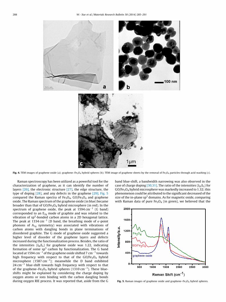
Fig. 4. TEM images of graphene oxide (a); graphene–Fe3O4 hybrid spheres (b); TEM image of graphene sheets by the removal of Fe3O4 particles through acid washing (c).
Fig. 5. Raman images of graphene oxide and graphene–Fe3O4 hybrid spheres.
W.- Xue et al. / Materials Research Bulletin 50 (2014) 285–291288
Raman spectroscopy has been utilized as a powerful tool for thecharacterization of graphene, as it can identify the number oflayers [26], the electronic structure [27], the edge structure, thetype of doping [28], and any defects in the graphene [29]. Fig. 5compared the Raman spectra of Fe3O4, GO/Fe3O4 and grapheneoxide. The Raman spectrum of the graphene oxide (in blue) becamebroader than that of GO/Fe3O4 hybrid microsphere (in red). In thespectrum of graphene oxide, the peak at 1594 cm�1 (G band)corresponded to an E2g mode of graphite and was related to thevibration of sp2-bonded carbon atoms in a 2D hexagonal lattice.The peak at 1334 cm�1 (D band, the breathing mode of k-pointphonons of A1g symmetry) was associated with vibrations ofcarbon atoms with dangling bonds in plane terminations ofdisordered graphite. The G mode of graphene oxide suggested ahigher level of disorder of the graphene layers and defectsincreased during the functionalization process. Besides, the ratio ofthe intensities (ID/IG) for graphene oxide was 1.22, indicatingformation of some sp3 carbon by functionalization. The G bandlocated at 1594 cm�1 of the graphene oxide shifted 7 cm�1 towardshigh frequency with respect to that of the GO/Fe3O4 hybridmicrosphere (1587 cm�1); meanwhile the D band exhibited24 cm�1 blue-shift towards high frequency with respect to thatof the graphene–Fe3O4 hybrid spheres (1310 cm�1). These blue-shifts might be explained by considering the charge doping byoxygen atoms or ions binding with the carbon dangling bondsduring oxygen RIE process. It was reported that, aside from the G
band blue-shift, a bandwidth narrowing was also observed in thecase of charge doping [30,31]. The ratio of the intensities (ID/IG) forGO/Fe3O4 hybrid microsphere was markedly increased to 1.32; thisphenomenon could be attributed to the significant decreased of thesize of the in-plane sp2 domains. As for magnetic oxide, comparingwith Raman data of pure Fe3O4 (in green), we believed that the
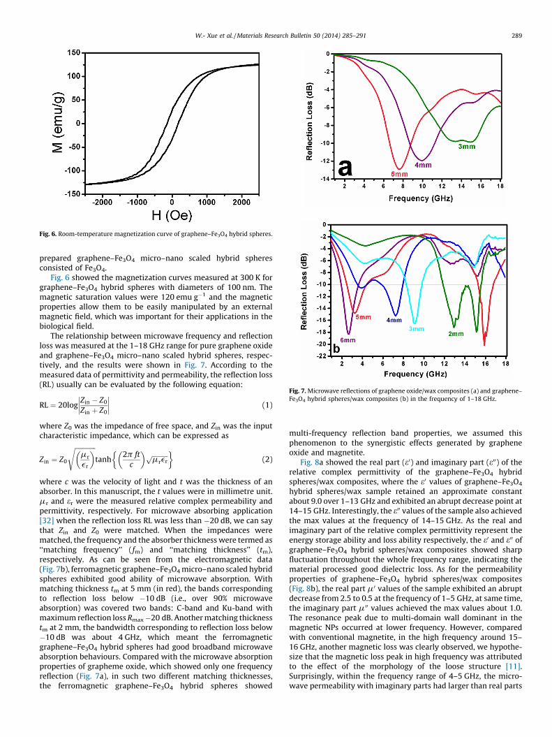
Fig. 6. Room-temperature magnetization curve of graphene–Fe3O4 hybrid spheres.
Fig. 7. Microwave reflections of graphene oxide/wax composites (a) and graphene–
Fe3O4 hybrid spheres/wax composites (b) in the frequency of 1–18 GHz.
W.- Xue et al. / Materials Research Bulletin 50 (2014) 285–291 289
prepared graphene–Fe3O4 micro–nano scaled hybrid spheresconsisted of Fe3O4.
Fig. 6 showed the magnetization curves measured at 300 K forgraphene–Fe3O4 hybrid spheres with diameters of 100 nm. Themagnetic saturation values were 120 emu g�1 and the magneticproperties allow them to be easily manipulated by an externalmagnetic field, which was important for their applications in thebiological field.
The relationship between microwave frequency and reflectionloss was measured at the 1–18 GHz range for pure graphene oxideand graphene–Fe3O4 micro–nano scaled hybrid spheres, respec-tively, and the results were shown in Fig. 7. According to themeasured data of permittivity and permeability, the reflection loss(RL) usually can be evaluated by the following equation:
RL ¼ 20logZin � Z0
Zin þ Z0
�������� (1)
where Z0 was the impedance of free space, and Zin was the inputcharacteristic impedance, which can be expressed as
Zin ¼ Z0
ffiffiffiffiffiffiffiffiffiffiffiffiffimr
er
� �stanh
2p ft
c
� � ffiffiffiffiffiffiffiffiffiffimrerp� �
(2)
where c was the velocity of light and t was the thickness of anabsorber. In this manuscript, the t values were in millimetre unit.mr and er were the measured relative complex permeability andpermittivity, respectively. For microwave absorbing application[32] when the reflection loss RL was less than �20 dB, we can saythat Zin and Z0 were matched. When the impedances werematched, the frequency and the absorber thickness were termed as‘‘matching frequency’’ (fm) and ‘‘matching thickness’’ (tm),respectively. As can be seen from the electromagnetic data(Fig. 7b), ferromagnetic graphene–Fe3O4 micro–nano scaled hybridspheres exhibited good ability of microwave absorption. Withmatching thickness tm at 5 mm (in red), the bands correspondingto reflection loss below �10 dB (i.e., over 90% microwaveabsorption) was covered two bands: C-band and Ku-band withmaximum reflection loss Rmax�20 dB. Another matching thicknesstm at 2 mm, the bandwidth corresponding to reflection loss below�10 dB was about 4 GHz, which meant the ferromagneticgraphene–Fe3O4 hybrid spheres had good broadband microwaveabsorption behaviours. Compared with the microwave absorptionproperties of grapheme oxide, which showed only one frequencyreflection (Fig. 7a), in such two different matching thicknesses,the ferromagnetic graphene–Fe3O4 hybrid spheres showed
multi-frequency reflection band properties, we assumed thisphenomenon to the synergistic effects generated by grapheneoxide and magnetite.
Fig. 8a showed the real part (e0) and imaginary part (e00) of therelative complex permittivity of the graphene–Fe3O4 hybridspheres/wax composites, where the e0 values of graphene–Fe3O4
hybrid spheres/wax sample retained an approximate constantabout 9.0 over 1–13 GHz and exhibited an abrupt decrease point at14–15 GHz. Interestingly, the e00 values of the sample also achievedthe max values at the frequency of 14–15 GHz. As the real andimaginary part of the relative complex permittivity represent theenergy storage ability and loss ability respectively, the e0 and e00 ofgraphene–Fe3O4 hybrid spheres/wax composites showed sharpfluctuation throughout the whole frequency range, indicating thematerial processed good dielectric loss. As for the permeabilityproperties of graphene–Fe3O4 hybrid spheres/wax composites(Fig. 8b), the real part m0 values of the sample exhibited an abruptdecrease from 2.5 to 0.5 at the frequency of 1–5 GHz, at same time,the imaginary part m00 values achieved the max values about 1.0.The resonance peak due to multi-domain wall dominant in themagnetic NPs occurred at lower frequency. However, comparedwith conventional magnetite, in the high frequency around 15–16 GHz, another magnetic loss was clearly observed, we hypothe-size that the magnetic loss peak in high frequency was attributedto the effect of the morphology of the loose structure [11].Surprisingly, within the frequency range of 4–5 GHz, the micro-wave permeability with imaginary parts had larger than real parts
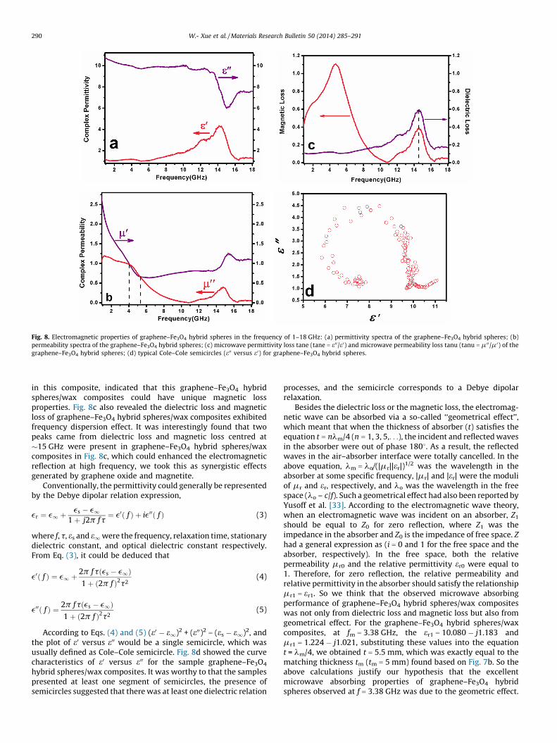
Fig. 8. Electromagnetic properties of graphene–Fe3O4 hybrid spheres in the frequency of 1–18 GHz: (a) permittivity spectra of the graphene–Fe3O4 hybrid spheres; (b)
permeability spectra of the graphene–Fe3O4 hybrid spheres; (c) microwave permittivity loss tane (tane = e00/e0) and microwave permeability loss tanu (tanu = m00/m0) of the
graphene–Fe3O4 hybrid spheres; (d) typical Cole–Cole semicircles (e00 versus e0) for graphene–Fe3O4 hybrid spheres.
W.- Xue et al. / Materials Research Bulletin 50 (2014) 285–291290
in this composite, indicated that this graphene–Fe3O4 hybridspheres/wax composites could have unique magnetic lossproperties. Fig. 8c also revealed the dielectric loss and magneticloss of graphene–Fe3O4 hybrid spheres/wax composites exhibitedfrequency dispersion effect. It was interestingly found that twopeaks came from dielectric loss and magnetic loss centred at�15 GHz were present in graphene–Fe3O4 hybrid spheres/waxcomposites in Fig. 8c, which could enhanced the electromagneticreflection at high frequency, we took this as synergistic effectsgenerated by graphene oxide and magnetite.
Conventionally, the permittivity could generally be representedby the Debye dipolar relation expression,
er ¼ e1 þes � e1
1 þ j2p ft¼ e0ð f Þ þ ie00ð f Þ (3)
where f, t, es and e1were the frequency, relaxation time, stationarydielectric constant, and optical dielectric constant respectively.From Eq. (3), it could be deduced that
e0ð f Þ ¼ e1 þ2p ftðes � e1Þ1 þ ð2p f Þ2t2
(4)
e00ð f Þ ¼ 2p ftðes � e1Þ1 þ ð2p f Þ2t2
(5)
According to Eqs. (4) and (5) (e0 � e1)2 + (e00)2 = (es � e1)2, andthe plot of e0 versus e00 would be a single semicircle, which wasusually defined as Cole–Cole semicircle. Fig. 8d showed the curvecharacteristics of e0 versus e00 for the sample graphene–Fe3O4
hybrid spheres/wax composites. It was worthy to that the samplespresented at least one segment of semicircles, the presence ofsemicircles suggested that there was at least one dielectric relation
processes, and the semicircle corresponds to a Debye dipolarrelaxation.
Besides the dielectric loss or the magnetic loss, the electromag-netic wave can be absorbed via a so-called ‘‘geometrical effect’’,which meant that when the thickness of absorber (t) satisfies theequation t = nlm/4 (n = 1, 3, 5,. . .), the incident and reflected wavesin the absorber were out of phase 1808. As a result, the reflectedwaves in the air–absorber interface were totally cancelled. In theabove equation, lm = lo/(|mr||er|)
1/2 was the wavelength in theabsorber at some specific frequency, |mr| and |er| were the moduliof mr and er, respectively, and lo was the wavelength in the freespace (lo = c/f). Such a geometrical effect had also been reported byYusoff et al. [33]. According to the electromagnetic wave theory,when an electromagnetic wave was incident on an absorber, Z1
should be equal to Z0 for zero reflection, where Z1 was theimpedance in the absorber and Z0 is the impedance of free space. Z
had a general expression as (i = 0 and 1 for the free space and theabsorber, respectively). In the free space, both the relativepermeability mr0 and the relative permittivity er0 were equal to1. Therefore, for zero reflection, the relative permeability andrelative permittivity in the absorber should satisfy the relationshipmr1 = er1. So we think that the observed microwave absorbingperformance of graphene–Fe3O4 hybrid spheres/wax compositeswas not only from dielectric loss and magnetic loss but also fromgeometrical effect. For the graphene–Fe3O4 hybrid spheres/waxcomposites, at fm = 3.38 GHz, the er1 = 10.080 � j1.183 andmr1 = 1.224 � j1.021, substituting these values into the equationt = lm/4, we obtained t = 5.5 mm, which was exactly equal to thematching thickness tm (tm = 5 mm) found based on Fig. 7b. So theabove calculations justify our hypothesis that the excellentmicrowave absorbing properties of graphene–Fe3O4 hybridspheres observed at f = 3.38 GHz was due to the geometric effect.
W.- Xue et al. / Materials Research Bulletin 50 (2014) 285–291 291
4. Conclusion
We synthesized graphene–Fe3O4 micro–nano scaled hybridspheres with the diameter of �100 nm via solvent-thermal route,which combined the hybridization growth of Fe3O4 nanoparticlesand graphene oxide in one single step. The hybrid spheres showeda homogenous phase without obviously interfaces betweengraphene and Fe3O4. Owing to the interfacial polarization andgood separation of magnetic properties, the interpenetratingconstitution of the materials brought good synergistic effects onthe electromagnetic wave absorbing properties: a multi-frequencyreflection band covered C-band and Ku-band with maximumreflection loss �20 dB as the matching thickness of 5 mm gave verypromising desire for lightweight and strong electromagneticattenuation applications.
References
[1] A.K. Cheetham, C.N.R. Rao, Science 318 (2007) 58–59.[2] J.M. Perez, T.O. Loughlin, F.J. Simeone, R. Weissleder, L. Josephson, J. Am. Chem.
Soc. 124 (2002) 2856–2857;J.M. Perez, F.J. Simeone, A. Tsourkas, L. Josephson, R. Weissleder, Nano Lett. 4(2002) 119–122;J.M. Perez, L. Josephson, T. O’Loughlin, D. Hogemann, R. Weissleder, Nat. Bio-technol. 20 (2002) 816–820.
[3] A.Y. Louie, M.M. Huber, E.T. Ahrens, U. Rothbacher, R. Moats, R.E. Jacobs, et al. Nat.Biotechnol. 18 (2000) 321–325.
[4] Z.W. Pan, Z.R. Dai, Z.L. Wang, Science 291 (2001) 1947.[5] Y. Sun, Y. Xia, Science 298 (2002) 2176–2179;
Y. Lu, Y. Yin, B.T. Mayers, Y. Xia, Nano Lett. 2 (2002) 183–186;Y.L. Wang, Y.N. Xia, Nano Lett. 4 (2002) 2047–2050.
[6] S.H. Gee, Y.K. Hong, D.W. Erickson, M.H. Park, J. Appl. Phys. 93 (2003) 7560–7562.[7] K. Woo, J. Hong, S. Choi, H. Lee, J. Ahn, C.S. Kim, Chem. Mater. 16 (2004) 2814–
2818.[8] H. Yoshikawa, K. Hayashida, Y. Kozuka, A. Horiguchi, K. Awaga, S. Bandow, Appl.
Phys. Lett. 85 (2004) 5297.[9] M. Ohnishi, Y. Kozuka, Q.L. Ye, H. Yoshikawa, K. Awaga, R. Matsuno, J. Mater.
Chem. 16 (2006) 3215.[10] Q.L. Ye, Y. Kozuka, H. Yoshikawa, K. Awaga, S. Bandow, S. Iijima, Phys. Rev. B 75
(2007) 224404.
[11] R. Zhao, K. Jia, J.J. Wei, J.X. Pu, X.B. Liu, Mater. Lett. 64 (2010) 457–459.[12] A.K. Geim, Science 324 (2009) 1530–1534.[13] Y. Zhang, J.W. Tan, H.L. Stoemer, P. Kim, Nature 438 (2005) 201.[14] X. Wang, L. Zhi, K. Mullen, Nano Lett. 8 (2008) 323.[15] Z.S. Wu, W.S. Ren, L. Wen, L.B. Gao, J.P. Zhao, Z.P. Chen, G.M. Zhou, F. Li, H.M. Chen,
ACS Nano 4 (2010) 3187.[16] G.M. Zhou, D.W. Wang, F. Li, L.L. Zhang, N. Li, Z.S. Wu, L. Wen, G.Q. Lu, H.M. Cheng,
Chem. Mater. 22 (2010) 5306.[17] Z. Xu, C. Gao, Nat. Commun. 2 (2011) 571.[18] R.C. Che, L.M. Peng, X.F. Duan, Q. Chen, X.L. Liang, Adv. Mater. 16 (2004) 401.[19] P. Xu, X.J. Han, C. Wang, D.H. Zhou, Z.S. Lv, A.H. Wen, X.H. Wang, B. Zhang, J. Phys.
Chem. B 112 (2008) 10443.[20] J.J. Liang, Y. Wang, Y. Huang, Y.F. Ma, Z.F. Liu, J.M. Cai, C.D. Zhang, H.J. Gao, Y.S.
Chen, Carbon 47 (2009) 922.[21] C. Wang, X.J. Han, P. Xu, X.L. Zhang, Y.C. Du, S.R. Hu, J.Y. Wang, X.H. Wang, Appl.
Phys. Lett. 98 (2011) 072906.[22] T.S. Wang, Z.H. Liu, M.M. Lu, B. Wen, Q.Y. Ouyang, Y.J. Chen, C.L. Zhu, P. Gao, C.Y. Li,
M.S. Cao, L.H. Qi, J. Appl. Phys. 113 (2013) 024314.[23] D.C. Marcano, D.V. Kosynkin, J.M. Berlin, A. Sinitskii, Z. Sun, A. Slesarev, L.B.
Alemany, W. Lu, J. Tour, ACS Nano 4 (8) (2010) 4806–4814.[24] Z.J. Fan, W. Kai, J. Yan, T. Wei, L.J. Zhi, J. Feng, Y.M. Ren, L.P. Song, F. Wei, ACS Nano 5
(2011) 191–198.[25] (a) T. Sharifi, E. Gracia-Espino, H.R. Barzegar, X. Jia, F. Nitze, G. Hu, P. Nordblad,
C.W. Tai, T. Wagberg, Nat. Commun., 4, doi:10.1038/ncomms3319(b) X. Wang, D.P. Yang, G. Huang, P. Huang, G. Shen, S. Guo, Y. Mei, D. Cui, J. Mater.Chem. 22 (2012) 17441–17444;(c) M. Quintana, M. Grzelczak, K. Spyrou, M. Calvaresi, S. Bals, B. Kooi, G.V.Tendeloo, P. Rudolf, F. Zerbetto, M. Prato, J. Am. Chem. Soc 134 (2012) 13310–13315;(d) S. Wang, L.A. Tang, Q. Bao, M. Lin, S. Deng, B.M. Goh, K.P. Loh, J. Am. Chem. Soc.131 (2009) 16832–16837.
[26] A.C. Ferrari, J.C. Meyer, V. Scardaci, C. Casiraghi, M. Lazzeri, F. Mauri, S. Piscanec, D.Jiang, K.S. Novoselov, S. Roth, A.K. Geim, Phys. Rev. Lett. 97 (2006) 187401.
[27] L.M. Malard, J. Nilsson, D.C. Elias, J.C. Plentz, E.S. Alves, A.H. Castro Neto, M.A.Pimenta, Phys. Rev. B 76 (2007) 201401.
[28] A.C. Ferrari, D.M. Basko, Nat. Nanotechnol. 8 (2013) 235.[29] R. Podila, R. Rao, R. Tsuchikawa, M. Ishigami, A.M. Rao, ACS Nano 6 (2012) 5784.[30] C.X. Cong, T. Yu, Z.H. Ni, L. Liu, Z.X. Shen, W. Huang, J. Phys. Chem. C 113 (2009)
6529–6532.[31] A. Das, S. Pisana, B. Chakraborty, S. Piscanec, S.K. Saha, U.V. Waghmare, K.S.
Novoselov, H.R. Krishnamurthy, A.K. Geim, A.C. Ferrari, A.K. Sood, Nat. Nanotech-nol. 3 (2008) 210.
[32] M.K. Debe, K.K. Kan, Thin Solid Films 186 (1990) 289–325.[33] A.N. Yusoff, M.H. Abdullah, S.H. Ahmad, S.F. Jusoh, A.A. Mansor, S.A.A. Hamid, J.
Appl. Phys. 92 (2002) 876–883.