gpus and gpu programming and gpu programming ... graphics on a personal computer was performed by a...
TRANSCRIPT
CSci 360 Computer Architecture 3GPUs and GPU Programming
Prof. Stewart Weiss
GPUs and GPU Programming
1 Contemporary GPU System Architecture
1.1 Historical Context
Up until 1999, the GPU did not exist. Graphics on a personal computer was performed by a video graphicsarray (VGA) controller, sometimes called a graphics accelerator. A VGA controller was a combinationof a memory controller and a display generator with attached DRAM. As it became less expensive tobuild more powerful processors, it also became less expensive to add more functionality to these graphicsaccelerators. In the 1990's, VGA controllers began to incorporate some three-dimensional (3D) functions,such as triangulation, rasterization, and texture mapping and shading. These operations are described below.
The availability of these more powerful graphics chips led software makers to create software that used thesechips, fueled by the public's insatiable desire for life-like real-time 3D graphics, and the demands of thecomputer gaming industry, the movie industry, and the television industry. Chip manufacturers completedthis cycle by responding in turn with more powerful chips. Eventually, this cycle of growth resulted ingraphics controllers that had as much processing power as the CPU itself, although their limited purposemade them unsuitable to be used as CPUs.
The �rst graphics processing unit (GPU), NVIDIA's GEForce 256, appeared in 1999. In addition to theoperations that had become standard by then, this chip incorporated functions to perform in hardwaretransforms (movement in 3D), lighting and shading (altering the color of surfaces of the scene based onlighting information.) In November 2006, NVIDIA's GeForce 8800 gave birth to their new GPU Computingmodel. The GeForce 8800 was based on the G80 architecture and brought several key innovations to GPUcomputing. The G80 series was the largest commercial GPU at the time, containing approximately 686million transistors. By 2008, eight generations of the GEForce had been built, some of which provided fullsupport for 3D graphics libraries such as Direct3D.
Over the next few years, the GPUs became more and more programmable, replacing �xed function dedicatedlogic by programmable processors. Integer arithmetic was replaced by �oating-point arithmetic, and the de-gree of parallelism within the chips increased dramatically. It was not long before chip manufacturers startedadding instructions and memory to the GPUs so that they could support general purpose programming, andthis turned them into fully general-purpose processors, known as GPGPUs. At this point the GPGPU is aprocessor with unprecedented �oating-point performance and programmability.
1.2 Di�erences Between GPUs and CPUs
GPUs do not �t into any classi�cation scheme. Parts of it are MIMD and parts of it are SIMD. The NVIDIAGeForce 8800 GTX, for example has 16 identical Tesla processors, each of which is a sort of multiprocessor.Thus, from a large scale view, it is MIMD. Each Tesla processor consists of eight streaming processors, witha SIMD architecture. Each streaming processor executes the same instruction on di�erent data. Within theprocessor there is a shared memory that each streaming processor can access.
Although the hardware is SIMD, the Tesla programmer interface creates the illusion that the multiprocessoris MIMD. It achieves this by making certain threads inactive when they are not supposed to execute agiven instruction, and by high level parallel �ne-grained multithreading. At its best, all threads are busy
1
CSci 360 Computer Architecture 3GPUs and GPU Programming
Prof. Stewart Weiss
all of the time. The hardware is more like SIMT � single instruction multiple thread, than SIMD. But ifthe programmer does not write the code carefully, the machine will not take advantage of the maximumparallelism possible.
A GPU is a multiprocessor, sometimes containing hundreds of processors. The intended purpose of a GPUis to perform graphics operations, which is what they do well, but they can be used for other computationsas well. So how are they di�erent from CPUs at this point?
• GPUs do not perform all of the operations that a CPU can perform; their instruction sets are narrowlyfocused on graphics acceleration.
• The programming interfaces to GPUs are high-level application programming interfaces such asOpenGL,Cg, and DirectX, together with high-level graphics shading languages such as C for Graphics (Cg) andthe High Level Shader Language (HLSL). These languages are supported by compilers that generateintermediate languages, which are optimized by the speci�c GPU driver software, which generates thethe speci�c machine instructions for the GPU.
• Graphics processing includes many stages in a pipeline of operations, including vertex shading, geom-etry shading, rasterization, and pixel shading. These operations, described below, are performed on amassively parallel scale in a pipe-lined fashion.
• Vertices can be drawn independently, and pixel fragments can be rendered independently. This inde-pendence allows the computation to proceed using many independent and parallel threads of control.
• GPUs are designed to work well on 4-tuples. This is because a vertex in three dimensions is representedby a set of four coordinates, (x, y, z, w), called homogeneous coordinates. The fourth coordinate,w, is used to facilitate projecting the 3D point into two-dimensions in a way that creates the illusion ofdepth (known to the artist as perspective drawing and to the mathematician as projective geometry.)Also, having the fourth coordinate makes the basic transformations of rotation, translation, and scalingobtainable by matrix multiplication. Pixels consist of four coordinates also, from a color space with analpha channel, (r, g, b, alpha). Vertices and pixels each consist of four 32-bit �oating point numbers.
• Unlike general purpose applications, graphics computations have working sets that can be hundreds ofmegabytes.
• There is much more data parallelism in graphics applications than general purpose applications.
A consequence of these di�erences is that
• GPUs do not rely on multi-level caches to overcome long latencies to memory. Instead, they rely onhaving enough threads to hide the latency and they use multithreading.
• GPUs rely on extensive parallelism to obtain high performance.
• GPU main memory is designed for high bandwidth rather than small latency. GPU's have smallermemories than CPUs.
• GPU processors are multithreaded and each is highly parallel. In the past, they had specializedprocessors for each stage of the pipeline, but more of them now have homogeneous processors.
• GPUs used to have four-stream SIMD processors within them, but now these are being replaced byregular processors and scalar instructions.
• GPUs have no need for double-precision �oating point instructions, but as they become used more andmore for non-graphical processing, this functionality is being added to them.
There is a growing base of general purpose applications that have been ported to GPUs. The term generalpurpose GPU, or GPGPU refers to a method of using GPUs for non-graphics applications. NVIDIA has de-veloped a programming language, CUDA (Compute Uni�ed Device Architecture) that enables programmersto write C code for GPUs.
2
CSci 360 Computer Architecture 3GPUs and GPU Programming
Prof. Stewart Weiss
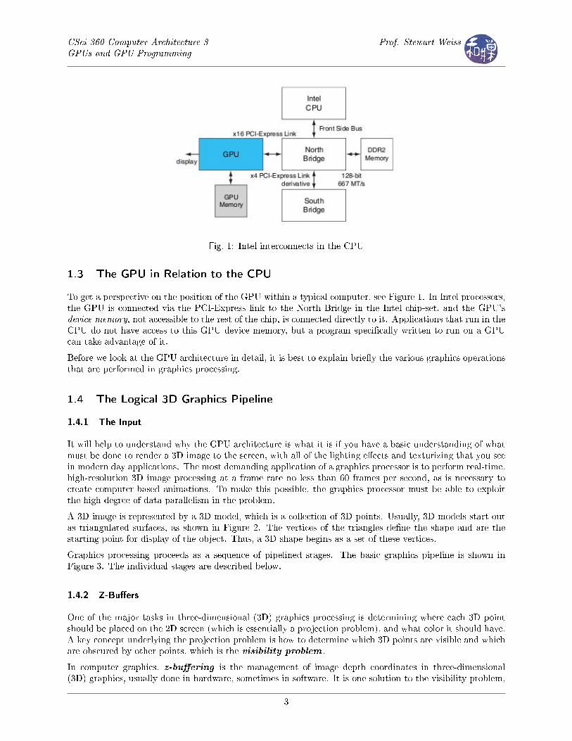
Fig. 1: Intel interconnects in the CPU
1.3 The GPU in Relation to the CPU
To get a perspective on the position of the GPU within a typical computer, see Figure 1. In Intel processors,the GPU is connected via the PCI-Express link to the North Bridge in the Intel chip-set, and the GPU'sdevice memory, not accessible to the rest of the chip, is connected directly to it. Applications that run in theCPU do not have access to this GPU device memory, but a program speci�cally written to run on a GPUcan take advantage of it.
Before we look at the GPU architecture in detail, it is best to explain brie�y the various graphics operationsthat are performed in graphics processing.
1.4 The Logical 3D Graphics Pipeline
1.4.1 The Input
It will help to understand why the GPU architecture is what it is if you have a basic understanding of whatmust be done to render a 3D image to the screen, with all of the lighting e�ects and texturizing that you seein modern day applications. The most demanding application of a graphics processor is to perform real-time,high-resolution 3D image processing at a frame rate no less than 60 frames per second, as is necessary tocreate computer-based animations. To make this possible, the graphics processor must be able to exploitthe high degree of data-parallelism in the problem.
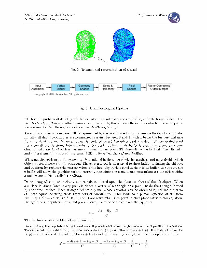
A 3D image is represented by a 3D model, which is a collection of 3D points. Usually, 3D models start outas triangulated surfaces, as shown in Figure 2. The vertices of the triangles de�ne the shape and are thestarting point for display of the object. Thus, a 3D shape begins as a set of these vertices.
Graphics processing proceeds as a sequence of pipelined stages. The basic graphics pipeline is shown inFigure 3. The individual stages are described below.
1.4.2 Z-Bu�ers
One of the major tasks in three-dimensional (3D) graphics processing is determining where each 3D pointshould be placed on the 2D screen (which is essentially a projection problem), and what color it should have.A key concept underlying the projection problem is how to determine which 3D points are visible and whichare obscured by other points, which is the visibility problem .
In computer graphics, z-bu�ering is the management of image depth coordinates in three-dimensional(3D) graphics, usually done in hardware, sometimes in software. It is one solution to the visibility problem,
3
CSci 360 Computer Architecture 3GPUs and GPU Programming
Prof. Stewart Weiss
Fig. 2: Triangulated representation of a head
Fig. 3: Graphics Logical Pipeline
which is the problem of deciding which elements of a rendered scene are visible, and which are hidden. Thepainter's algorithm is another common solution which, though less e�cient, can also handle non-opaquescene elements. Z-bu�ering is also known as depth bu�ering .
An arbitrary point on a surface in 3D is represented by the coordinates (x,y,z), where z is the depth coordinate.Initially all depth coordinates are normalized, varying between 0 and 1, with 1 being the furthest distancefrom the viewing plane. When an object is rendered by a 3D graphics card, the depth of a generated pixel(its z coordinate) is stored into the z-bu�er (or depth bu�er). This bu�er is usually arranged as a two-dimensional array (x-y) with one element for each screen pixel. The intensity value for that pixel (its colorand alpha channel) are stored in a parallel 2D bu�er called the refresh bu�er .
When multiple objects in the scene must be rendered in the same pixel, the graphics card must decide whichobject's pixel is closest to the observer. The chosen depth is then saved to the z-bu�er, replacing the old one,and its intensity replaces the current value of the intensity at that pixel in the refresh bu�er. In the end, thez-bu�er will allow the graphics card to correctly reproduce the usual depth perception: a close object hidesa farther one. This is called z-culling .
Determining which pixel is closest is a calculation based upon the planar surfaces of the 3D object. Whena surface is triangulated, every point is either a vertex of a triangle or a point inside the triangle formedby the three vertices. Each triangle de�nes a plane, whose equation can be obtained by solving a systemof linear equations using those three sets of coordinates. This leads to a planar equation of the formAx + By + Cz = D. where A, B, C, and D are constants. Each point in that plane satis�es this equation.By algebraic manipulation, if x and y are known, z can be obtained from the equation
z =−Ax−By + D
C
The z-values so obtained lie between 0 and 1.0.
For e�ciency, the depth-bu�ering algorithm will process each scan line (horizontal line of pixels) in succession.Two adjacent pixels di�er only in their x-coordinate: (x, y) is followed by(x + 1, y). If the depth value for(x, y) is z, then the depth value z′ for (x + 1, y) can be obtained by a single subtraction operation, since
z′ =−A(x + 1)−By + D
C=−Ax−By + D
C− A
C= z − A
C
4
CSci 360 Computer Architecture 3GPUs and GPU Programming
Prof. Stewart Weiss
and A/C is a stored constant for each plane.
1.4.3 The Pipeline Stages
Input Assembler The input assembler receives the 3D representation of the scene as a collection ofgeometric primitives such as points, lines, and vertices. It then distributes the vertices to the vertex shader.The input assembler typically assembles vertices into several di�erent primitive types such as line lists,triangle strips, or primitives with adjacency.
The input data may be a list of vertices, lines and so on, but it might also include an index bu�er. Withoutan index bu�er, a vertex might appear multiple times in the input to the graphics processor, because thevertex data was arranged in the order in which the larger primitives (e.g., lines, triangles) would be processed.Rather than storing the vertices themselves in an array, the array could contain references to vertices, whichwould be in a secondary structure. This array is an index bu�er . By using an index bu�er, each vertex isstored exactly once, and references to it as a part of larger primitives are the indices into this array.
The input may also include a collection of textures that are to be applied to the scene to be displayed. Youcan think of a texture as a two-dimensional shape, usually a rectangle, containing colors or an image to beapplied to a surface.
Vertex Shading Shader programs in general determine how lighting and shadows interact with the surfacesto be rendered. A vertex shader is a graphics processing function that maps vertices onto the screen andadds special e�ects to objects in a 3D environment by performing mathematical operations on the objects'vertex data. One of its purposes is to transform each vertex's 3D position in virtual space to the 2Dcoordinate at which it appears on the screen, as well as a depth value for the Z-bu�er, and then to applycolor to it.
Examples of vertex shading e�ects include matrix palette skinning, which allows programmers to createrealistic character animation with up to 32 "bones" per joint; deformation of surfaces, which gives developersthe power to create realistic surfaces such as waves; and vertex morphing, which is used to morph trianglemeshes from one shape to another, providing smooth skeletal animation. Vertex shaders are run once foreach input vertex. Although vertex shaders can manipulate properties such as position, color, and texturecoordinate, they cannot create new vertices. The output of the vertex shader goes to the next stage in thepipeline, which is either a geometry shader if present or the rasterizer otherwise.
Geometry Shading Geometry shading is the stage of the graphics pipeline after vertex shading. Itspurpose is to enhance the details and accuracy of the 2D image by working at a larger degree of granularitythan individual vertices. Its inputs consist of geometric primitives consisting of more than one vertex, suchas lines and triangles. A geometry shader can take as its input, for example, the three points of a triangleand output intermediate points that can be used to re�ne the surface. It can only do this by operating withgreater granularity. The geometry shader can modify the positions and orientation of the primitives.
Rasterization The word "raster" was originally used in the raster scan of cathode ray tubes (CRT), whichpaint the image line by line; the term is now used to mean a grid of pixels. Rasterization is a processfor converting vectorized input to a bitmap form, i.e. a 2D array of pixels. Given a triangle, for example,represented by three vertices, it determines the locations of all pixels and pixel fragments that lie inside,or on the edge of, this triangle. There can be pixel fragments because a triangle is a mathematical objectconsisting of lines of in�nitely small width that can intersect pixels rather than lie between them. Therefore,a single pixel can lie on each side of a line segment. The fragment of the pixel on the inside edge of atriangle's perimeter is a pixel fragment belonging to that triangle.
The rasterization stage actually does other processing as well. Typically it also does clipping , meaningthrowing away regions that are outside of the view frustum . A frustum is a 3D shape that can bedescribed as a 4-sided pyramid with its top lopped o�. It is the 3D analog of a trapezoid. When you view
5
CSci 360 Computer Architecture 3GPUs and GPU Programming
Prof. Stewart Weiss
a scene in perspective, you are looking at a frustum lying on its side usually. The front plane is the bottomof the pyramid, and the back plane is the lopped-o� top. This is the view frustum.
The rasterization step typically does z-culling of pixels. As it is generating pixels, it can discover that someof them are behind others and should be culled. When this step is �nished, what is left are the visible pixelsand pixel fragments, represented by their screen positions and their depth values. These are passed to thepixel shader.
Pixel Shading A pixel shader is a function that computes the color and other attributes of each pixel orpixel fragment. Pixel shaders range from always outputting the same color, to applying a lighting value, todoing bump mapping, shadows, specular highlights, translucency and other phenomena. They can alter thedepth of the pixel (for Z-bu�ering), or output more than one color if multiple render targets are active. Apixel shader alone cannot produce very complex e�ects, because it operates only on a single pixel, withoutknowledge of a scene's geometry or of neighboring pixels.
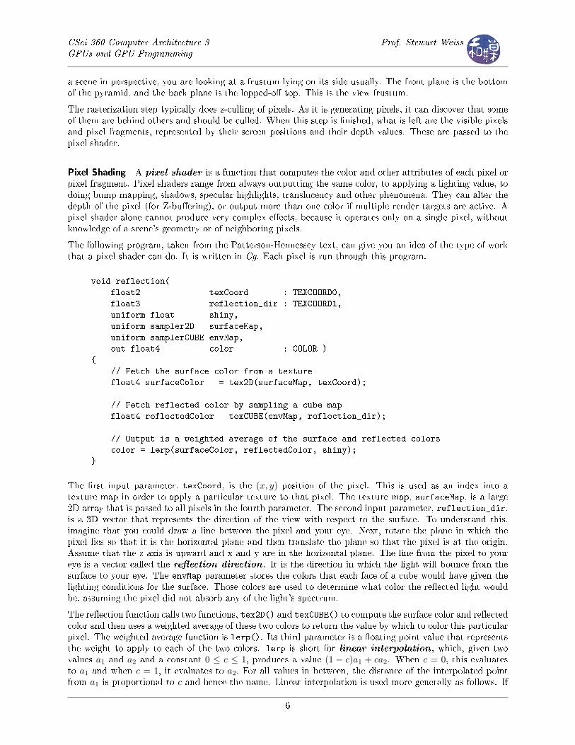
The following program, taken from the Patterson-Hennessey text, can give you an idea of the type of workthat a pixel shader can do. It is written in Cg. Each pixel is run through this program.
void reflection(
float2 texCoord : TEXCOORD0,
float3 reflection_dir : TEXCOORD1,
uniform float shiny,
uniform sampler2D surfaceMap,
uniform samplerCUBE envMap,
out float4 color : COLOR )
{
// Fetch the surface color from a texture
float4 surfaceColor = tex2D(surfaceMap, texCoord);
// Fetch reflected color by sampling a cube map
float4 reflectedColor = texCUBE(envMap, reflection_dir);
// Output is a weighted average of the surface and reflected colors
color = lerp(surfaceColor, reflectedColor, shiny);
}
The �rst input parameter, texCoord, is the (x, y) position of the pixel. This is used as an index into atexture map in order to apply a particular texture to that pixel. The texture map, surfaceMap, is a large2D array that is passed to all pixels in the fourth parameter. The second input parameter, reflection_dir,is a 3D vector that represents the direction of the view with respect to the surface. To understand this,imagine that you could draw a line between the pixel and your eye. Next, rotate the plane in which thepixel lies so that it is the horizontal plane and then translate the plane so that the pixel is at the origin.Assume that the z-axis is upward and x and y are in the horizontal plane. The line from the pixel to youreye is a vector called the re�ection direction . It is the direction in which the light will bounce from thesurface to your eye. The envMap parameter stores the colors that each face of a cube would have given thelighting conditions for the surface. Those colors are used to determine what color the re�ected light wouldbe, assuming the pixel did not absorb any of the light's spectrum.
The re�ection function calls two functions, tex2D() and texCUBE() to compute the surface color and re�ectedcolor and then uses a weighted average of these two colors to return the value by which to color this particularpixel. The weighted average function is lerp(). Its third parameter is a �oating point value that representsthe weight to apply to each of the two colors. lerp is short for linear interpolation , which, given twovalues a1 and a2 and a constant 0 ≤ c ≤ 1, produces a value (1 − c)a1 + ca2. When c = 0, this evaluatesto a1 and when c = 1, it evaluates to a2. For all values in between, the distance of the interpolated pointfrom a1 is proportional to c and hence the name. Linear interpolation is used more generally as follows. If
6
CSci 360 Computer Architecture 3GPUs and GPU Programming
Prof. Stewart Weiss
f(x) is a function of x all of whose values are either hard to compute or unknown, and an approximation orestimate of it is needed, and two values are known, at, say at points x1 and x2, then a linear interpolationof f(x) between the pair of points is given by (1 − c)f(x1) + cf(x2), 0 ≤ c ≤ 1, which in e�ect treats the
function as a linear function (a straight line) between the points. The approximation to f , denoted f̂(x),would be de�ned by letting c = (x− x1)/(x2 − x1).
The Relation Between the Graphics Pipeline and the GPU
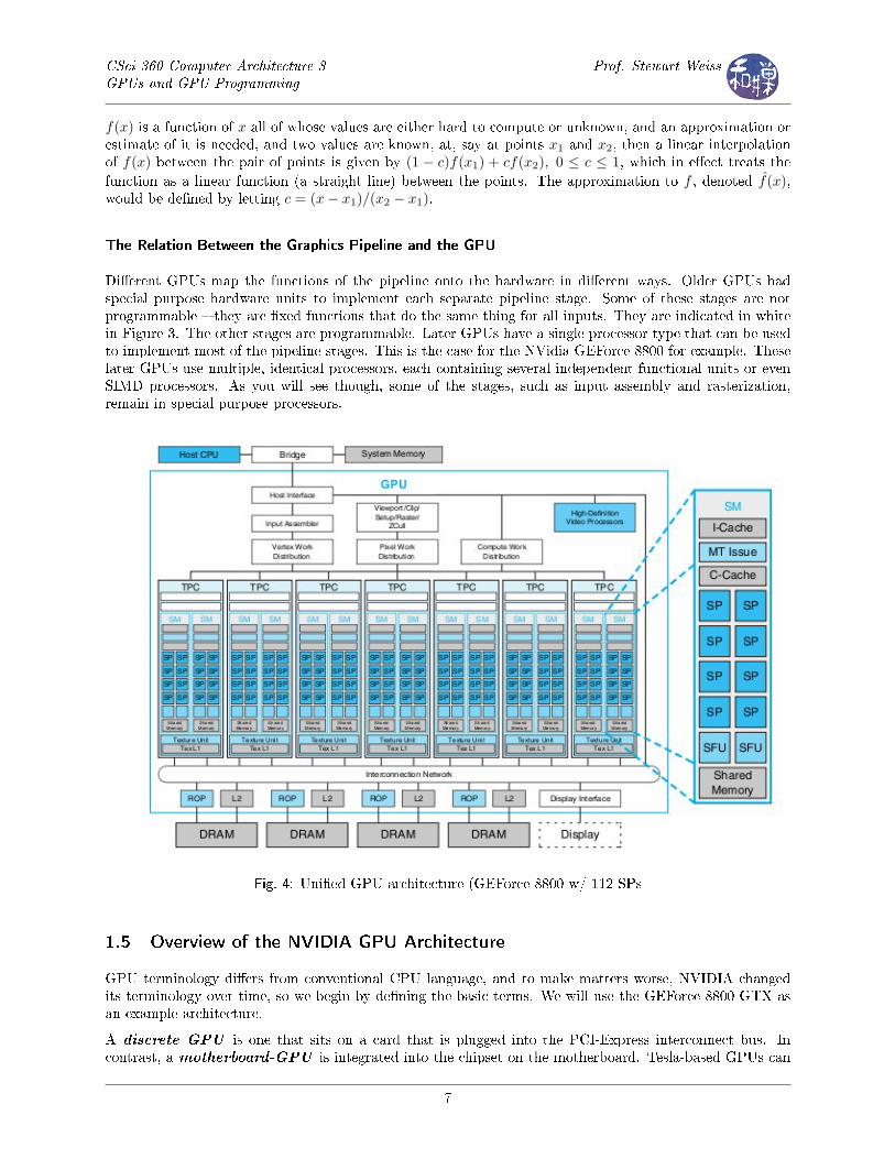
Di�erent GPUs map the functions of the pipeline onto the hardware in di�erent ways. Older GPUs hadspecial purpose hardware units to implement each separate pipeline stage. Some of these stages are notprogrammable � they are �xed functions that do the same thing for all inputs. They are indicated in whitein Figure 3. The other stages are programmable. Later GPUs have a single processor type that can be usedto implement most of the pipeline stages. This is the case for the NVidia GEForce 8800 for example. Theselater GPUs use multiple, identical processors, each containing several independent functional units or evenSIMD processors. As you will see though, some of the stages, such as input assembly and rasterization,remain in special purpose processors.
Fig. 4: Uni�ed GPU architecture (GEForce 8800 w/ 112 SPs
1.5 Overview of the NVIDIA GPU Architecture
GPU terminology di�ers from conventional CPU language, and to make matters worse, NVIDIA changedits terminology over time, so we begin by de�ning the basic terms. We will use the GEForce 8800 GTX asan example architecture.
A discrete GPU is one that sits on a card that is plugged into the PCI-Express interconnect bus. Incontrast, a motherboard-GPU is integrated into the chipset on the motherboard. Tesla-based GPUs can
7
CSci 360 Computer Architecture 3GPUs and GPU Programming
Prof. Stewart Weiss
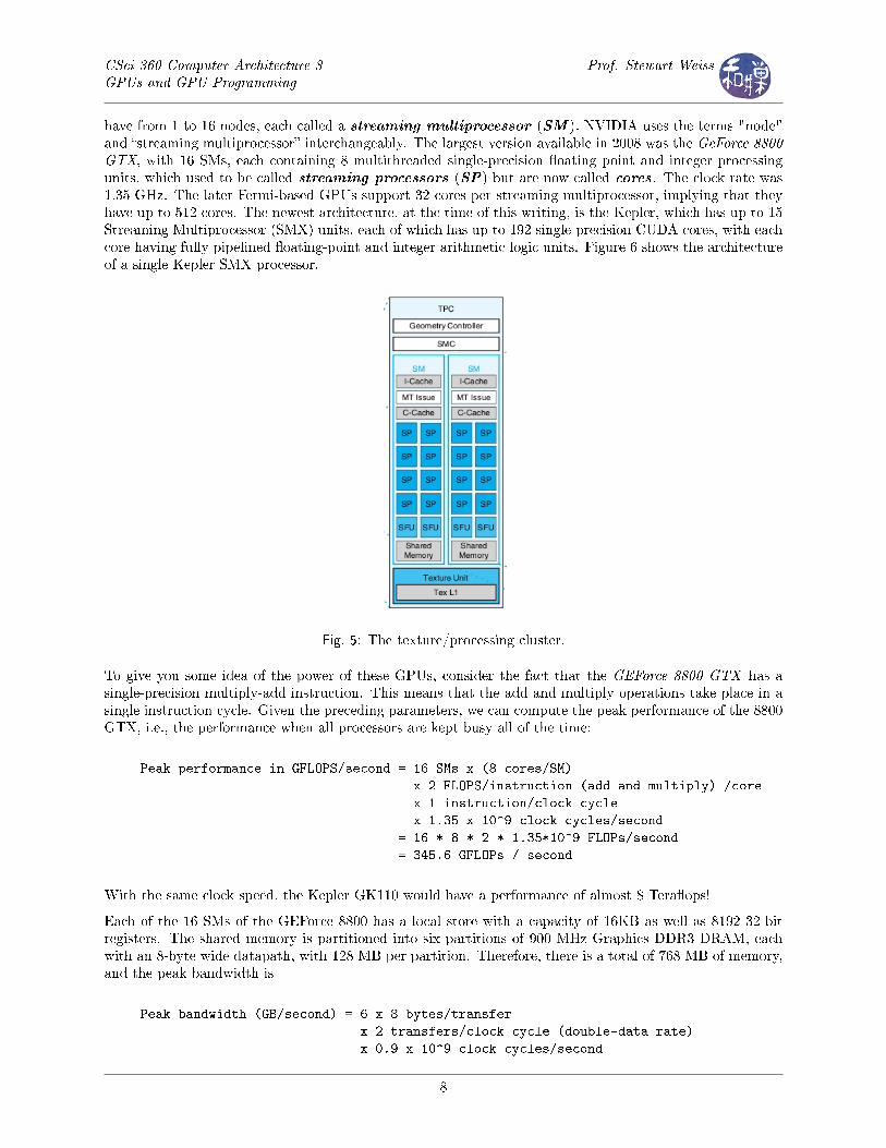
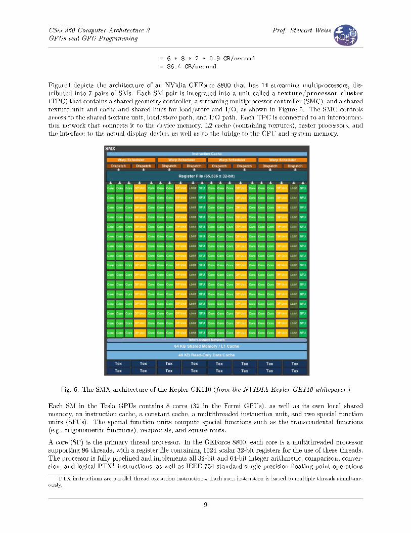
have from 1 to 16 nodes, each called a streaming multiprocessor (SM ). NVIDIA uses the terms "node"and �streaming multiprocessor� interchangeably. The largest version available in 2008 was the GeForce 8800GTX, with 16 SMs, each containing 8 multithreaded single-precision �oating point and integer processingunits, which used to be called streaming processors (SP) but are now called cores. The clock rate was1.35 GHz. The later Fermi-based GPUs support 32 cores per streaming multiprocessor, implying that theyhave up to 512 cores. The newest architecture, at the time of this writing, is the Kepler, which has up to 15Streaming Multiprocessor (SMX) units, each of which has up to 192 single-precision CUDA cores, with eachcore having fully pipelined �oating-point and integer arithmetic logic units. Figure 6 shows the architectureof a single Kepler SMX processor.
Fig. 5: The texture/processing cluster.
To give you some idea of the power of these GPUs, consider the fact that the GEForce 8800 GTX has asingle-precision multiply-add instruction. This means that the add and multiply operations take place in asingle instruction cycle. Given the preceding parameters, we can compute the peak performance of the 8800GTX, i.e., the performance when all processors are kept busy all of the time:
Peak performance in GFLOPS/second = 16 SMs x (8 cores/SM)
x 2 FLOPS/instruction (add and multiply) /core
x 1 instruction/clock cycle
x 1.35 x 10^9 clock cycles/second
= 16 * 8 * 2 * 1.35*10^9 FLOPs/second
= 345.6 GFLOPs / second
With the same clock speed, the Kepler GK110 would have a performance of almost 8 Tera�ops!
Each of the 16 SMs of the GEForce 8800 has a local store with a capacity of 16KB as well as 8192 32-bitregisters. The shared memory is partitioned into six partitions of 900 MHz Graphics DDR3 DRAM, eachwith an 8-byte wide datapath, with 128 MB per partition. Therefore, there is a total of 768 MB of memory,and the peak bandwidth is
Peak bandwidth (GB/second) = 6 x 8 bytes/transfer
x 2 transfers/clock cycle (double-data rate)
x 0.9 x 10^9 clock cycles/second
8
CSci 360 Computer Architecture 3GPUs and GPU Programming
Prof. Stewart Weiss
= 6 * 8 * 2 * 0.9 GB/second
= 86.4 GB/second
Figure4 depicts the architecture of an NVidia GEForce 8800 that has 14 streaming multiprocessors, dis-tributed into 7 pairs of SMs. Each SM pair is integrated into a unit called a texture/processor cluster(TPC) that contains a shared geometry controller, a streaming multiprocessor controller (SMC), and a sharedtexture unit and cache and shared lines for load/store and I/O, as shown in Figure 5. The SMC controlsaccess to the shared texture unit, load/store path, and I/O path. Each TPC is connected to an interconnec-tion network that connects it to the device memory, L2 cache (containing textures), raster processors, andthe interface to the actual display device, as well as to the bridge to the CPU and system memory.
Fig. 6: The SMX architecture of the Kepler GK110 (from the NVIDIA Kepler GK110 whitepaper.)
Each SM in the Tesla GPUs contains 8 cores (32 in the Fermi GPUs), as well as its own local sharedmemory, an instruction cache, a constant cache, a multithreaded instruction unit, and two special functionunits (SFUs). The special function units compute special functions such as the transcendental functions(e.g., trigonometric functions), reciprocals, and square roots.
A core (SP) is the primary thread processor. In the GEForce 8800, each core is a multithreaded processorsupporting 96 threads, with a register �le containing 1024 scalar 32-bit registers for the use of these threads.The processor is fully pipelined and implements all 32-bit and 64-bit integer arithmetic, comparison, conver-sion, and logical PTX1 instructions, as well as IEEE 754 standard single precision �oating point operations
1 PTX instructions are parallel thread execution instructions. Each such instruction is issued to multiple threads simultane-
ously.
9
CSci 360 Computer Architecture 3GPUs and GPU Programming
Prof. Stewart Weiss
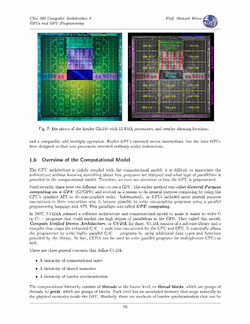
Fig. 7: Die photo of the Kepler GK110 with 15 SMX processors, and overlay showing locations.
and a compatible add/multiply operation. Earlier GPUs executed vector instructions, but the later GPUswere designed so that core processors executed ordinary scalar instructions.
1.6 Overview of the Computational Model
The GPU architecture is tightly coupled with the computational model; it is di�cult to appreciate thearchitecture without knowing something about how programs are designed and what type of parallelism isprovided in the computational model. Therefore, we turn our attention to how the GPU is programmed.
Until recently, there were two di�erent ways to use a GPU. The earlier method was calledGeneral Purposecomputing on a GPU (GPGPU) and evolved as a means to do general purpose computing by using theGPU's graphics API to do non-graphics tasks. Subsequently, as GPUs included more general purposeinstructions in their instruction sets, it became possible to write non-graphics programs using a parallelprogramming language and API. This paradigm was called GPU computing .
In 2007, NVIDIA released a software architecture and computational model to make it easier to write Cor C++ programs that could exploit the high degree of parallelism in the GPU. They called this model,Compute Uni�ed Device Architecture , or CUDA, for short. CUDA consists of a software library and acompiler that maps the enhanced C/C++ code into instructions for the GPU and CPU. It essentially allowsthe programmer to write highly parallel C/C++ programs by using additional data types and functionsprovided by the library. In fact, CUDA can be used to write parallel programs for multiple-core CPUs aswell.
There are three general concepts that de�ne CUDA:
• A hierarchy of computational units
• A hierarchy of shared memories
• A hierarchy of barrier synchronization
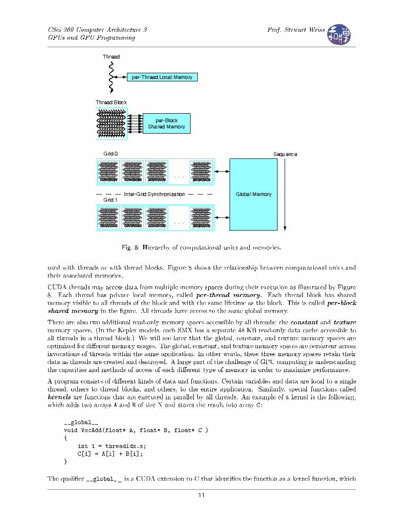
The computational hierarchy consists of threads at the lowest level, to thread blocks, which are groups ofthreads, to grids, which are groups of blocks. Each level has an associated memory that maps naturally tothe physical memories inside the GPU. Similarly, there are methods of barrier synchronization that can be
10
CSci 360 Computer Architecture 3GPUs and GPU Programming
Prof. Stewart Weiss
Fig. 8: Hierarchy of computational units and memories.
used with threads or with thread blocks. Figure 8 shows the relationship between computational units andtheir associated memories.
CUDA threads may access data from multiple memory spaces during their execution as illustrated by Figure8. Each thread has private local memory, called per-thread memory . Each thread block has sharedmemory visible to all threads of the block and with the same lifetime as the block. This is called per-blockshared memory in the �gure. All threads have access to the same global memory.
There are also two additional read-only memory spaces accessible by all threads: the constant and texture
memory spaces. (In the Kepler models, each SMX has a separate 48 KB read-only data cache accessible toall threads in a thread block.) We will see later that the global, constant, and texture memory spaces areoptimized for di�erent memory usages. The global, constant, and texture memory spaces are persistent acrossinvocations of threads within the same application. In other words, these three memory spaces retain theirdata as threads are created and destroyed. A large part of the challenge of GPU computing is understandingthe capacities and methods of access of each di�erent type of memory in order to maximize performance.
A program consists of di�erent kinds of data and functions. Certain variables and data are local to a singlethread, others to thread blocks, and others, to the entire application. Similarly, special functions calledkernels are functions that are executed in parallel by all threads. An example of a kernel is the following,which adds two arrays A and B of size N and stores the result into array C:
__global__
void VecAdd(float* A, float* B, float* C )
{
int i = threadIdx.x;
C[i] = A[i] + B[i];
}
The quali�er __global__ is a CUDA extension to C that identi�es the function as a kernel function, which
11
CSci 360 Computer Architecture 3GPUs and GPU Programming
Prof. Stewart Weiss
means that every thread executes it. Each thread is given a unique integer identi�er, which in this case isstored in the variable threadIdx.x. To call this function from the main program, one would use the syntax
int main()
{
...
// Kernel invocation with one block of N threads
int numBlocks = 1;
dim3 threadsPerBlock(N);
VecAdd<�<�<numBlocks, threadsPerBlock>�>�>(A, B, C);
}
The triple-angle brackets <�<�<...>�>�> identify the execution con�guration of the kernel, which indicateshow many blocks per grid (up to three dimensions) and how many threads per block (up to three dimensions).In this example, the grid consists of one block because numBlocks = 1, and the block is a set of N threads.threadsPerBlock is declared as a dim3, which is a 3-dimensional structure having x, y, and z members; theinitialization sets x=N and y=1 and z=1 by default.
This is the �avor of computing in CUDA, but there is much more to be said about it later. For now, theimportant observation is that the CUDA programming model requires an underlying architecture that canexecute many threads extremely quickly, and be able to switch among groups of threads as well. It alsohas to provide the di�erent memory spaces in an e�cient way. This leads us to explore the multithreadingcapabilities of the GPU.
1.7 The GPU's Multithreaded Multiprocessor
The GPU processor's multithreading is designed to achieve several goals:
• To hide the latency of memory loads and texture fetches from DRAM and shared block memories.
Memory accesses can take hundreds of processor cycles. Multithreading allows the processor to switchto another thread while one thread is waiting for a load or texture fetch to complete. The extremelyhigh degree of multithreading can keep many cores busy even though many threads might be stalledwaiting for memory loads, because if there are enough active threads, then the probability that thereare threads to keep all cores busy will be high.
• To support �ne-grained parallel graphics shader programming models and parallel computing models.
Graphics shader programs typically execute many di�erent stages dynamically, from vertex shading topixel shading. Because of this, the streaming multiprocessors are designed to execute di�erent threadprograms concurrently.
• To virtualize the physical processors as threads and thread blocks in order to make them highly scalable.
Furthermore, each thread can have its own private registers, private memory, program counter, andthread execution state, and can execute its own independent code sequence. To make all of thispossible, the GPU multiprocessor is hardware multithreaded, managing hundreds of threads withoutscheduling overhead. Threads within a thread block can synchronize with each other using a barriersynchronization instruction (like the one we saw in Chapter 7 notes).
• To simplify the parallel programming model so that the programmer only has to write serial kernelfunctions.
All of the concurrency in the CUDA extensions to C and C++ takes place in kernel functions. Thishas the potential to simplify the logic of many data parallel programs.
12
CSci 360 Computer Architecture 3GPUs and GPU Programming
Prof. Stewart Weiss
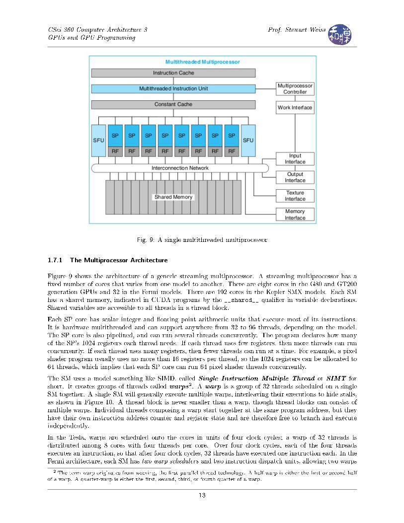
Fig. 9: A single multithreaded multiprocessor
1.7.1 The Multiprocessor Architecture
Figure 9 shows the architecture of a generic streaming multiprocessor. A streaming multiprocessor has a�xed number of cores that varies from one model to another. There are eight cores in the G80 and GT200generation GPUs and 32 in the Fermi models. There are 192 cores in the Kepler SMX models. Each SMhas a shared memory, indicated in CUDA programs by the __shared__ quali�er in variable declarations.Shared variables are accessible to all threads in a thread block.
Each SP core has scalar integer and �oating point arithmetic units that execute most of its instructions.It is hardware multithreaded and can support anywhere from 32 to 96 threads, depending on the model.The SP core is also pipelined, and can run several threads concurrently. The program declares how manyof the SP's 1024 registers each thread needs. If each thread uses few registers, then more threads can runconcurrently. If each thread uses many registers, then fewer threads can run at a time. For example, a pixelshader program usually uses no more than 16 registers per thread, so the 1024 registers can be allocated to64 threads, which implies that each SP core can run 64 pixel shader threads concurrently.
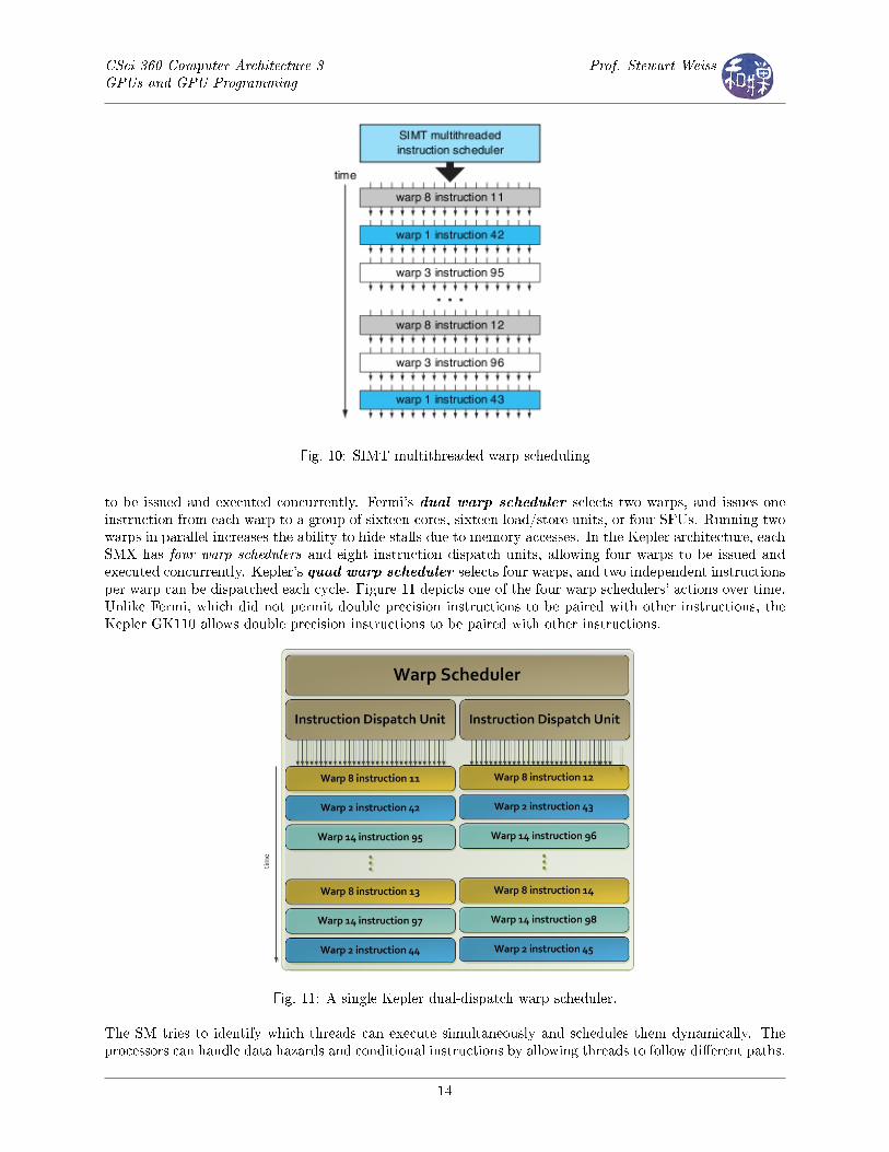
The SM uses a model something like SIMD, called Single Instruction Multiple Thread or SIMT forshort. It creates groups of threads called warps2. A warp is a group of 32 threads scheduled on a singleSM together. A single SM will generally execute multiple warps, interleaving their executions to hide stalls,as shown in Figure 10. A thread block is never smaller than a warp, though thread blocks can consist ofmultiple warps. Individual threads composing a warp start together at the same program address, but theyhave their own instruction address counter and register state and are therefore free to branch and executeindependently.
In the Tesla, warps are scheduled onto the cores in units of four clock cycles; a warp of 32 threads isdistributed among 8 cores with four threads per core. Over four clock cycles, each of the four threadsexecutes an instruction, so that after four clock cycles, 32 threads have executed one instruction each. In theFermi architecture, each SM has two warp schedulers and two instruction dispatch units, allowing two warps
2 The term warp originates from weaving, the �rst parallel thread technology. A half-warp is either the �rst or second half
of a warp. A quarter-warp is either the �rst, second, third, or fourth quarter of a warp.
13
CSci 360 Computer Architecture 3GPUs and GPU Programming
Prof. Stewart Weiss
Fig. 10: SIMT multithreaded warp scheduling
to be issued and executed concurrently. Fermi's dual warp scheduler selects two warps, and issues oneinstruction from each warp to a group of sixteen cores, sixteen load/store units, or four SFUs. Running twowarps in parallel increases the ability to hide stalls due to memory accesses. In the Kepler architecture, eachSMX has four warp schedulers and eight instruction dispatch units, allowing four warps to be issued andexecuted concurrently. Kepler's quad warp scheduler selects four warps, and two independent instructionsper warp can be dispatched each cycle. Figure 11 depicts one of the four warp schedulers' actions over time.Unlike Fermi, which did not permit double precision instructions to be paired with other instructions, theKepler GK110 allows double precision instructions to be paired with other instructions.
Fig. 11: A single Kepler dual-dispatch warp scheduler.
The SM tries to identify which threads can execute simultaneously and schedules them dynamically. Theprocessors can handle data hazards and conditional instructions by allowing threads to follow di�erent paths.
14
CSci 360 Computer Architecture 3GPUs and GPU Programming
Prof. Stewart Weiss
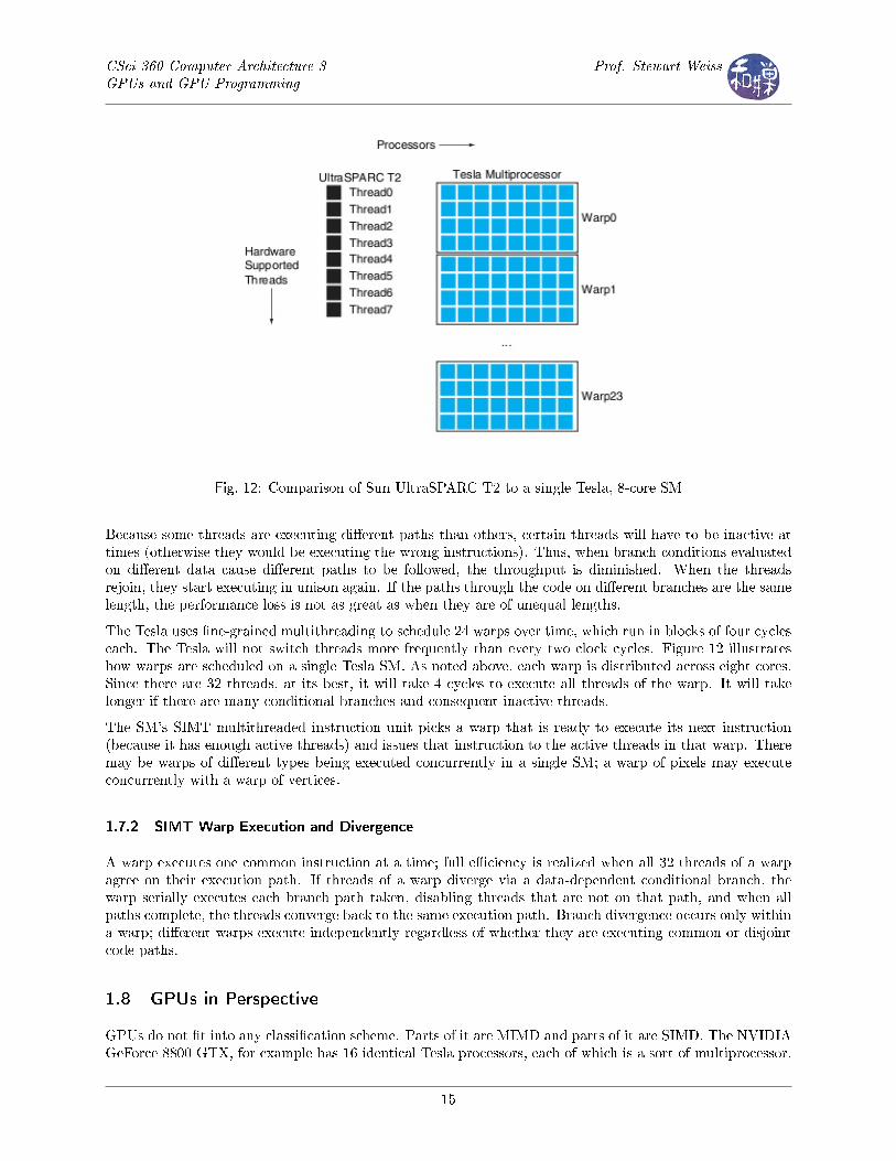
Fig. 12: Comparison of Sun UltraSPARC T2 to a single Tesla, 8-core SM
Because some threads are executing di�erent paths than others, certain threads will have to be inactive attimes (otherwise they would be executing the wrong instructions). Thus, when branch conditions evaluatedon di�erent data cause di�erent paths to be followed, the throughput is diminished. When the threadsrejoin, they start executing in unison again. If the paths through the code on di�erent branches are the samelength, the performance loss is not as great as when they are of unequal lengths.
The Tesla uses �ne-grained multithreading to schedule 24 warps over time, which run in blocks of four cycleseach. The Tesla will not switch threads more frequently than every two clock cycles. Figure 12 illustrateshow warps are scheduled on a single Tesla SM. As noted above, each warp is distributed across eight cores.Since there are 32 threads, at its best, it will take 4 cycles to execute all threads of the warp. It will takelonger if there are many conditional branches and consequent inactive threads.
The SM's SIMT multithreaded instruction unit picks a warp that is ready to execute its next instruction(because it has enough active threads) and issues that instruction to the active threads in that warp. Theremay be warps of di�erent types being executed concurrently in a single SM; a warp of pixels may executeconcurrently with a warp of vertices.
1.7.2 SIMT Warp Execution and Divergence
A warp executes one common instruction at a time; full e�ciency is realized when all 32 threads of a warpagree on their execution path. If threads of a warp diverge via a data-dependent conditional branch, thewarp serially executes each branch path taken, disabling threads that are not on that path, and when allpaths complete, the threads converge back to the same execution path. Branch divergence occurs only withina warp; di�erent warps execute independently regardless of whether they are executing common or disjointcode paths.
1.8 GPUs in Perspective
GPUs do not �t into any classi�cation scheme. Parts of it are MIMD and parts of it are SIMD. The NVIDIAGeForce 8800 GTX, for example has 16 identical Tesla processors, each of which is a sort of multiprocessor.
15
CSci 360 Computer Architecture 3GPUs and GPU Programming
Prof. Stewart Weiss
Thus, from a large scale view, it is MIMD. Each Tesla processor consists of eight streaming processors, witha SIMD architecture. Each streaming processor executes the same instruction on di�erent data. Within theprocessor there is a shared memory that each streaming processor can access.
Although the hardware is SIMD, the Tesla programmer interface creates the illusion that the multiprocessoris MIMD. It achieves this by making certain threads inactive when they are not supposed to execute a giveninstruction, and by high level parallel �ne-grained multithreading. At its best, all 32 threads in a warp arebusy all of the time. The hardware is more like SIMT � single instruction multiple thread, than SIMD. Butif the programmer does not write the code carefully, the machine will not take advantage of the maximumparallelism possible.
2 GPU Programming and CUDA
There are really two fundamental issues in programming a GPU � correctness and performance. Of course itis imperative that the programs are correct, but because the reason that one chooses to write a program torun on a multiprocessor is to decrease running time and/or increase problem size, performance is almost asimportant. Thus, while a programmer can generally ignore the design of the SIMT architecture and ignorehow warps are scheduled and executed in terms of correctness, he or she can greatly improve performanceby having threads in a warp execute the same code path and access memory in nearby addresses, and takeadvantage of knowledge of how global and shared memory are accessed.
Another issue is a practical one; how does one actually write general purpose programs that can be run ona GPU? There are di�erent approaches to this problem, but the easiest solution is to use NVIDIA's CUDAextension to the C/C++ language. These notes present an overview of CUDA Version 4.0. They are notintended as a reference manual nor as a technical guide. Most of the material comes from the NVIDIACUDA C Programming Guide, Version 4.0.
CUDA extends C by adding constants, types, and functions that expose the capabilities of a GPU. As notedearlier, it consists primarily of three key abstractions:
• a hierarchy of thread groups,
• shared memories, and
• barrier synchronization,
that allow the programmer to write programs that have �ne-grained data parallelism and thread parallelism,as well as coarse-grained data parallelism and task parallelism.
For the purpose of writing correct programs, it is enough to learn the syntax and semantics of a relativelysmall subset of CUDA, but for writing programs with optimal performance, it is important to understandthe underlying execution model and the memory model. We start with an overview of the memory modeland then look at some of the details of CUDA.
2.1 The Di�erent Types of Memory Accesses
There are various levels of memory that a thread can access explicitly - thread private, shared, constant,texture, and global. An instruction that accesses addressable memory might need to be re-issued multipletimes depending on the distribution of the memory addresses across the threads within the warp. How thedistribution a�ects the instruction throughput this way is speci�c to each type of memory and described inthe following sections. For example, for global memory, as a general rule, the more scattered the addressesare, the more reduced the throughput is. For shared memory, certain patterns result in higher bandwidth.
16
CSci 360 Computer Architecture 3GPUs and GPU Programming
Prof. Stewart Weiss
2.1.1 Global Memory Accesses
Global memory is o�-chip and generally has access times that are on the order of a hundred times longerthan the on-chip shared memory and caches. Therefore, one wants to minimize access to global memory.Unfortunately, the on-chip shared memory is often not large enough to store all of the data needed by thethreads executing within the thread blocks. The problem facing the programmer is understanding the moste�cient ways to move data between global memory and shared or thread private memory.
Global memory instructions support reading or writing words of size equal to 1, 2, 4, 8, or 16 bytes. Anyaccess (via a variable or a pointer) to data residing in global memory compiles to a single global memoryinstruction if and only if the size of the data type is 1, 2, 4, 8, or 16 bytes and the data is naturally aligned(i.e. its address is a multiple of that size). If the read (or write) requests from multiple threads can be madeto addresses in global memory that satisfy these constraints, then the reads (or writes) are coalesced into asingle instruction of higher bandwidth. This will be illustrated by example below.
2.1.2 Shared Memory Accesses
Because it is on-chip, the shared memory space is much faster than the local and global memory spaces.In fact, for all threads of a warp, accessing shared memory is fast as long as there are no bank con�icts
between the threads, as detailed below.
To achieve high bandwidth, shared memory is divided into equally-sized memory modules, called banks,which can be accessed simultaneously. Any memory read or write request made of n addresses that fall inn distinct memory banks can therefore be serviced simultaneously, yielding an overall bandwidth that is ntimes as high as the bandwidth of a single module.
However, if two addresses of a memory request fall in the same memory bank, there is a bank con�ict and theaccess has to be serialized. The hardware splits a memory request with bank con�icts into as many separatecon�ict-free requests as necessary, decreasing throughput by a factor equal to the number of separate memoryrequests. If the number of separate memory requests is n, the initial memory request is said to cause n-waybank con�icts.
To get maximum performance, it is therefore important to understand how memory addresses map to memorybanks in shared memory in order to schedule the memory requests so as to minimize bank con�icts.
For devices of compute-capability 1.x, shared memory has 16 banks that are organized such that successive32-bit words are assigned to successive banks, i.e. interleaved. Each bank has a bandwidth of 32 bits per twoclock cycles. A shared memory request for a warp is split into two memory requests, one for each half-warp,that are issued independently. As a consequence, there can be no bank con�ict between a thread belongingto the �rst half of a warp and a thread belonging to the second half of the same warp.3 Again, this is bestillustrated with an example.
2.2 Host and Device: What Runs Where
A program runs as two separate pieces: the host code and the device code . Host code is code that runson the host CPU. All references to the concept of the host are references to the CPU that spawned the GPUcomputation. In the Tesla and Fermi models, there could be only one host using the GPU at a time, butthe Kepler allows multiple hosts to share the GPU. Device code is code that runs on the GPU.
2.3 CUDA Extensions to C Types
CUDA adds vector types to the standard set of C elementary types. To be precise, for each of the types
3 For devices of compute-capability 2.x, shared memory has 32 banks. Therefore, unlike for devices of lower compute
capability, there may be bank con�icts between a thread belonging to the �rst half of a warp and a thread belonging to the
second half of the same warp.
17
CSci 360 Computer Architecture 3GPUs and GPU Programming
Prof. Stewart Weiss
char, uchar, int, uint, short, ushort, long, ulong, longlong, ulonglong, float
if X is one of these types, then there are vector types X1, X2, X3, and X4. For example, there are typesint1, int2, int3, and int4. The term vector type is a misnomer � these are not vectors, but structures.The 1st, 2nd, 3rd, and 4th components are accessible through the members x, y, z, and w, respectively. Forexample, if we declare
uint3 point;
then point.x, point.y, and point.z are the members of point. There are also double1 and double2, butnot double3 or double4.
The type dim3 is a an extension of uint3. It is used to specify the dimensions of things such as threadblocks and grids. Unlike uint3 though, when an object of type dim3 is declared , its constructor initializesall uninitialized components to the value 1. For example,
dim3 block(64, 64);
speci�es that block is 64 by 64 by 1, because the z member is set to 1.
2.4 Variable Quali�ers: Where Things Are Located
The following rules can be used to determine in which memory a variable resides.
1. An automatic variable declared in device code without any of the quali�ers __device__, __shared__and __constant__ usually resides in a register.
2. The __device__ quali�er declares a variable that resides on the device (meaning global memory), hasthe lifetime of an application, and is accessible from all the threads within the grid and from the hostthrough the runtime library (with speci�c functions designed to allow the host program to access theGPU's device memory.)
3. The __shared__ quali�er, optionally used together with __device__, declares a variable that it residesin the shared memory space of a thread block, has the lifetime of the block, and is only accessible fromall the threads within the block.
4. The __constant__ quali�er, optionally used together with __device__, declares a variable that residesin constant memory space, has the lifetime of an application, and is accessible from all the threadswithin the grid and from the host through the runtime library (with speci�c functions.)
2.5 Kernels
A kernel is a C function that is executed in parallel by more than one CUDA thread, as opposed to only oncelike an ordinary C function. A kernel is de�ned using the __global__ declaration speci�er. For example,
// kernel definition
__global__
void VecAdd(float* A, float* B, float* C )
{
int i = threadIdx.x;
C[i] = A[i] + B[i];
}
18
CSci 360 Computer Architecture 3GPUs and GPU Programming
Prof. Stewart Weiss
speci�es to the compiler that VecAdd() is a kernel. The number of threads that execute the kernel isdetermined by how the function is called. CUDA has a special execution con�guration syntax for thispurpose. Any call to a __global__ function must specify the execution con�guration for that call. Theexecution con�guration de�nes the dimension of the grid and blocks that will be used to execute the functionon the device. The syntax of the call is
function_name <�<�< Dg, Db, Ns, S >�>�>(argument_list );
where
• Dg is of type int or dim3 and speci�es the dimension and size of the grid, such that Dg.x * Dg.y *Dg.z equals the number of blocks being launched4;
• Db is of type int or dim3 and speci�es the dimension of the block. Db.x * Db.y * Db.z equals thenumber of threads being launched in each block.
• Ns is of type size_t and speci�es the number of bytes in shared memory that is dynamically allocatedper block for this call in addition to the statically allocated memory; this dynamically allocated memoryis used by any of the variables declared as an external array. Ns is an optional argument which defaultsto 0.
• S denotes a cudastream_t, which we will ignore here. It is an optional argument that defaults to 0.
We could invoke the above kernel in the main program as follows:
int main()
{
...
// Kernel invocation with N threads
VecAdd<�<�<1, N>�>�>(A, B, C);
}
In this case, Dg=1 and Db=N, so there is there is a single block containing N threads.
Each thread that executes the kernel is given a unique thread ID that is accessible within the kernel throughthe built-in threadIdx variable. The threadIdX variable is of type uint3, so (threadIdx.x, threadIdx.y,
threadIdx.z) are the coordinates of the thread within the block. Coordinates are Cartesian, not matrix. Inother words, the x coordinate is the column position and the y coordinate is the row position.
Each block is given a unique block ID that is accessible within the kernel through the built-in blockIdx
variable. The blockIdX variable is of type uint3, so (blockIdx.x, blockIdx.y, blockIdx.z) are thecoordinates of the block within the grid.
The dimensions of the grid are speci�ed with up to three dimensions and these dimensions are accessible toeach thread in the kernel through the built-in blockDim variable, which is of type dim3.
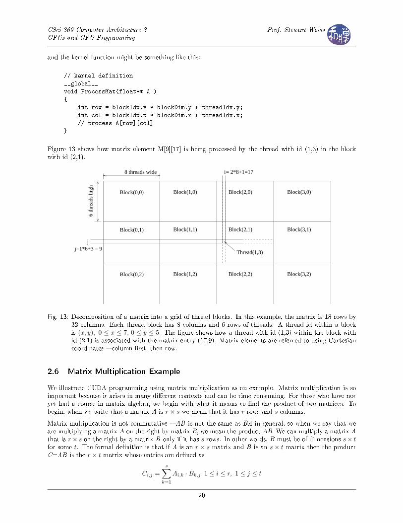
To illustrate, suppose we want to process a matrix M that has 32 columns and 18 rows by dividing it into agrid that has 4 columns and 3 rows of blocks, as shown in Figure 13. Each block will consist of 6 rows and8 columns of unique threads. The main program would call our kernel using the execution con�guration
dim3 gridSize(4,3);
dim3 blockSize(8,6);
float A[32][48];
ProcessMatrix<�<�<gridSize, blockSize>�>�>(A);
4 Dg.z must be equal to 1 for devices of compute capability 1.x.
19
CSci 360 Computer Architecture 3GPUs and GPU Programming
Prof. Stewart Weiss
and the kernel function might be something like this:
// kernel definition
__global__
void ProcessMat(float** A )
{
int row = blockIdx.y * blockDim.y + threadIdx.y;
int col = blockIdx.x * blockDim.x + threadIdx.x;
// process A[row][col]
}
Figure 13 shows how matrix element M[9][17] is being processed by the thread with id (1,3) in the blockwith id (2,1).
Block(0,0)
Block(0,1)
Block(0,2)
Block(1,0)
Block(1,1)
Block(1,2) Block(2,2)
Block(2,1)
Block(2,0) Block(3,0)
Block(3,1)
Block(3,2)
Thread(1,3)
i= 2*8+1=17
j
8 threads wide
6 th
read
s hi
gh
j=1*6+3 = 9
Fig. 13: Decomposition of a matrix into a grid of thread blocks. In this example, the matrix is 18 rows by32 columns. Each thread block has 8 columns and 6 rows of threads. A thread id within a blockis (x, y), 0 ≤ x ≤ 7, 0 ≤ y ≤ 5. The �gure shows how a thread with id (1,3) within the block withid (2,1) is associated with the matrix entry (17,9). Matrix elements are referred to using Cartesiancoordinates � column �rst, then row.
2.6 Matrix Multiplication Example
We illustrate CUDA programming using matrix multiplication as an example. Matrix multiplication is soimportant because it arises in many di�erent contexts and can be time-consuming. For those who have notyet had a course in matrix algebra, we begin with what it means to �nd the product of two matrices. Tobegin, when we write that a matrix A is r × s we mean that it has r rows and s columns.
Matrix multiplication is not commutative � AB is not the same as BA in general, so when we say that weare multiplying a matrix A on the right by matrix B, we mean the product AB. We can multiply a matrix Athat is r× s on the right by a matrix B only if it has s rows. In other words, B must be of dimensions s× tfor some t. The formal de�nition is that if A is an r × s matrix and B is an s× t matrix then the productC=AB is the r × t matrix whose entries are de�ned as
Ci,j =s∑
k=1
Ai,k ·Bk,j 1 ≤ i ≤ r, 1 ≤ j ≤ t
20
CSci 360 Computer Architecture 3GPUs and GPU Programming
Prof. Stewart Weiss
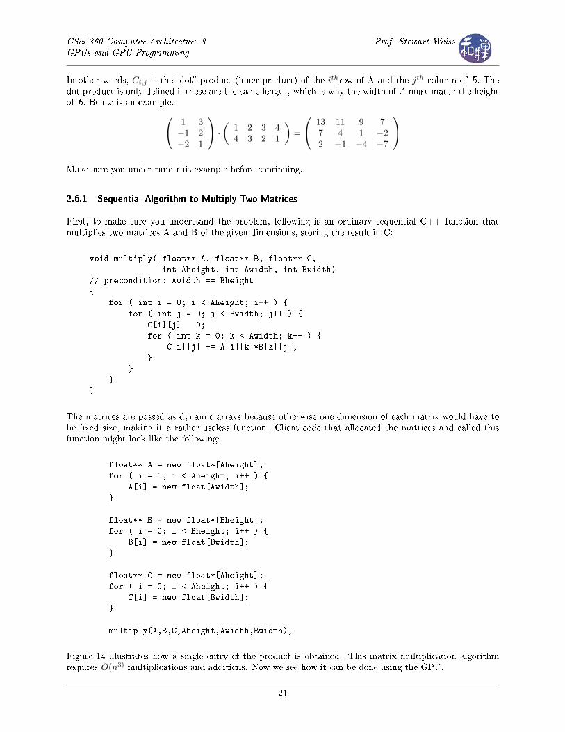
In other words, Ci,j is the �dot� product (inner product) of the ithrow of A and the jth column of B. Thedot product is only de�ned if these are the same length, which is why the width of A must match the heightof B. Below is an example. 1 3
−1 2−2 1
·(
1 2 3 44 3 2 1
)=
13 11 9 77 4 1 −22 −1 −4 −7
Make sure you understand this example before continuing.
2.6.1 Sequential Algorithm to Multiply Two Matrices
First, to make sure you understand the problem, following is an ordinary sequential C++ function thatmultiplies two matrices A and B of the given dimensions, storing the result in C:
void multiply( float** A, float** B, float** C,
int Aheight, int Awidth, int Bwidth)
// precondition: Awidth == Bheight
{
for ( int i = 0; i < Aheight; i++ ) {
for ( int j = 0; j < Bwidth; j++ ) {
C[i][j] = 0;
for ( int k = 0; k < Awidth; k++ ) {
C[i][j] += A[i][k]*B[k][j];
}
}
}
}
The matrices are passed as dynamic arrays because otherwise one dimension of each matrix would have tobe �xed size, making it a rather useless function. Client code that allocated the matrices and called thisfunction might look like the following:
float** A = new float*[Aheight];
for ( i = 0; i < Aheight; i++ ) {
A[i] = new float[Awidth];
}
float** B = new float*[Bheight];
for ( i = 0; i < Bheight; i++ ) {
B[i] = new float[Bwidth];
}
float** C = new float*[Aheight];
for ( i = 0; i < Aheight; i++ ) {
C[i] = new float[Bwidth];
}
multiply(A,B,C,Aheight,Awidth,Bwidth);
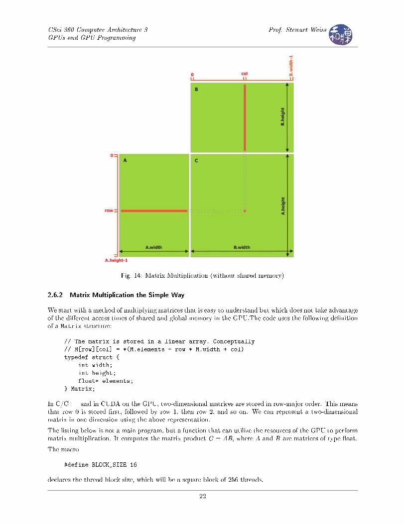
Figure 14 illustrates how a single entry of the product is obtained. This matrix multiplication algorithmrequires O(n3) multiplications and additions. Now we see how it can be done using the GPU.
21
CSci 360 Computer Architecture 3GPUs and GPU Programming
Prof. Stewart Weiss
Fig. 14: Matrix Multiplication (without shared memory)
2.6.2 Matrix Multiplication the Simple Way
We start with a method of multiplying matrices that is easy to understand but which does not take advantageof the di�erent access times of shared and global memory in the GPU.The code uses the following de�nitionof a Matrix structure:
// The matrix is stored in a linear array. Conceptually
// M[row][col] = *(M.elements + row * M.width + col)
typedef struct {
int width;
int height;
float* elements;
} Matrix;
In C/C++ and in CUDA on the GPU, two-dimensional matrices are stored in row-major order. This meansthat row 0 is stored �rst, followed by row 1, then row 2, and so on. We can represent a two-dimensionalmatrix in one dimension using the above representation.
The listing below is not a main program, but a function that can utilize the resources of the GPU to performmatrix multiplication. It computes the matrix product C = AB, where A and B are matrices of type �oat.
The macro
#define BLOCK_SIZE 16
declares the thread block size, which will be a square block of 256 threads.
22
CSci 360 Computer Architecture 3GPUs and GPU Programming
Prof. Stewart Weiss
The Algorithm This code is an implementation of matrix multiplication that does not take advantage ofthe shared memory within each SM (streaming multiprocessor). There will be a thread for each cell of theC result matrix. Let A be an M by N matrix and B, a N by R matrix. We assume that M,N, and R aredivisible by 16, the block size for this implementation.
The A and B matrices are copied from host memory to device memory. There, a kernel is run on a grid ofblocks of threads, each of which computes a single cell of C. To compute a single cell C[i][j] of C, it hasto read the ith row of A and the jth column of B, each of size N. Each cell does this. Many cells read the ith
row of A and many read the jth row of B, but only one does both of these uniquely.
To be clear, each row of A is read R times (for each column of B) and each column of B is read M times(for each row of A). Therefore, A is read R times from global memory and B is read M times. The basicsteps are
1. Allocate memory on the device for matrix A, and copy A onto the device's global memory.
2. Do the same for matrix B.
3. Allocate space on the device for C, the matrix product.
4. Compute the shape of the grid and the number of blocks needed to cover the product matrix C.
5. Launch the kernel with the grid and blocks.
6. When the kernel is done, copy matrix C from the device memory to host memory.
7. Free the device memory used by A, B, and C.
The listing follows.
Listing 1: Matrix multiplication without shared memory
/∗CUDA−based MATRIX MULTIPLICATION Without Using Shared Memory
Functions from CUDA used here in c lude :cudaError_t cudaMalloc ( void ∗∗ devPtr , s i ze_t count )
This a l l o c a t e s count bytes o f l i n e a r memory on the GPU and re tu rn sin ∗devPtr a po in t e r to the a l l o c a t e d memory . The a l l o c a t e d memoryi s s u i t ab l y a l i gned f o r any kind o f v a r i ab l e . The memory i s not zeroed .cudaMalloc ( )r e tu rn s cudaErrorMemoryAllocation in case o f f a i l u r e .cudaSuccess on suc c e s s .
cudaError_t cudaMemcpy( void ∗ dst , const void ∗ src , s i z e_t count ,enum cudaMemcpyKind kind )
This c op i e s count bytes from the memory area pointed to by s r c to thememory area pointed to by dst , where kind i s one o f
cudaMemcpyHostToHost ,cudaMemcpyHostToDevice ,cudaMemcpyDeviceToHost , orcudaMemcpyDeviceToDevice ,
and s p e c i f i e s the d i r e c t i o n o f the copy . The memory areas may not over lap .Ca l l i ng cudaMemcpy ( ) with dst and s r c po i n t e r s that do not match thed i r e c t i o n o f the copy r e s u l t s in an undef ined behavior .
∗/
#inc lude <s td i o . h>#inc lude <math . h>#inc lude <s t d l i b . h>
23
CSci 360 Computer Architecture 3GPUs and GPU Programming
Prof. Stewart Weiss
#inc lude <cuda . h>#inc lude <cuda_runtime_api . h>#inc lude "matrixmult . h"
#de f i n e BLOCK_SIZE 16
// Forward d e c l a r a t i on o f the matrix mu l t i p l i c a t i o n ke rne l ( in s epara t e l i s t i n g )__global__ void MatMulKernel ( const Matrix , const Matrix , Matrix ) ;
/∗Matrix mu l t i p l i c a t i o n − Host codeMatrix dimensions are assumed to be mu l t i p l e s o f BLOCK_SIZE
∗/void MatMul( const Matrix A, const Matrix B, Matrix C){
s i ze_t s i z e ;
// Dec lare the matrix that w i l l r e s i d e on the dev i c e ( the GPU)Matrix d_A;d_A. width = A. width ;d_A. he ight = A. he ight ;
/∗ Calcu la te i t s s i z e in bytes ∗/s i z e = A. width ∗ A. he ight ∗ s i z e o f ( f l o a t ) ;
/∗ Next a l l o c a t e space f o r d_A on the dev i c e . This uses the func t i oncudaMalloc ( ) . I t f i l l s d_A. e lements with the l o c a t i o n o f the s t a r to f s t o rage f o r d_A. ∗/
cudaMalloc(&d_A. elements , s i z e ) ;
/∗ Next , copy the array from the host memory to the dev i ce memoryus ing cudaMemCpy ( ) . ∗/
cudaMemcpy(d_A. elements , A. elements , s i z e , cudaMemcpyHostToDevice ) ;
/∗ Repeat the above s t ep s f o r the matrix B ∗/Matrix d_B;d_B. width = B. width ;d_B. he ight = B. he ight ;
s i z e = B. width ∗ B. he ight ∗ s i z e o f ( f l o a t ) ;cudaMalloc(&d_B. elements , s i z e ) ;cudaMemcpy(d_B. elements , B. elements , s i z e , cudaMemcpyHostToDevice ) ;
/∗ Repeat almost a l l o f the s t ep s f o r the C matrix . We do not copy i tfrom host memory because i t g e t s computed on the dev i c e and sent backto the host .
∗/Matrix d_C;d_C. width = C. width ;d_C. he ight = C. he ight ;s i z e = C. width ∗ C. he ight ∗ s i z e o f ( f l o a t ) ;cudaMalloc(&d_C. elements , s i z e ) ;
/∗ I t i s time to invoke the ke rne l on the GPU. The ke rne l i s run bys e v e r a l streaming mu l t i p r o c e s s o r s . The C r e s u l t matrix i s decomposedin to square b locks o f s i z e BLOCK_SIZE by BLOCK_SIZE. Each o f the sei s computed by a block o f threads . There w i l l be a g r id o f such b locks .I f the B matrix i s R c e l l s wide and the A matrix i s M c e l l s high , thenC i s M by R. Assuming R and M are mu l t i p l e s o f BLOCK_SIZE, the g r id
24
CSci 360 Computer Architecture 3GPUs and GPU Programming
Prof. Stewart Weiss
i s o f width R/BLOCK_SIZE and o f he ight M/BLOCK_SIZE. The next twoi n s t r u c t i o n s d e f i n e the block and gr id dimensions .
∗/dim3 dimBlock (BLOCK_SIZE, BLOCK_SIZE) ;dim3 dimGrid (B. width / dimBlock . x , A. he ight / dimBlock . y ) ;
/∗ Now the ke rne l i s invoked on t h i s g r id o f b locks o f threads ∗/MatMulKernel<<<dimGrid , dimBlock>>>(d_A, d_B, d_C) ;
/∗ When the ke rne l completes , we read C from dev i ce memory back tohost memory .
∗/cudaMemcpy(C. elements , d_C. elements , s i z e , cudaMemcpyDeviceToHost ) ;
/∗cudaError_t cudaFree ( void ∗ devPtr )This f r e e s the memory space pointed to by devPtr , which must have beenreturned by a prev ious c a l l to cudaMalloc ( ) or cudaMallocPitch ( ) .Otherwise , or i f cudaFree ( devPtr ) has a l r eady been c a l l e d be fore ,an e r r o r i s returned . I f devPtr i s 0 , no opera t i on i s performed .
∗/cudaFree (d_A. e lements ) ;cudaFree (d_B. e lements ) ;cudaFree (d_C. e lements ) ;
}
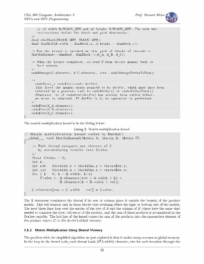
The matrix multiplication kernel is in the listing below:
Listing 2: Matrix multiplication kernel.
// Matrix mu l t i p l i c a t i o n ke rne l c a l l e d by MatMul ( )__global__ void MatMulKernel (Matrix A, Matrix B, Matrix C){
/∗ Each thread computes one element o f Cby accumulating r e s u l t s i n to Cvalue
∗/f l o a t Cvalue = 0 ;i n t k ;i n t row = blockIdx . y ∗ blockDim . y + threadIdx . y ;i n t c o l = blockIdx . x ∗ blockDim . x + threadIdx . x ;f o r ( k = 0 ; k < A. width ; k++)
Cvalue += A. e lements [ row ∗ A. width + k ] ∗B. e lements [ k ∗ B. width + co l ] ;
C. e lements [ row ∗ C. width + co l ] = Cvalue ;}
The if statement terminates the thread if its row or column place it outside the bounds of the productmatrix. This will happen only in those blocks that overhang either the right or bottom side of the matrix.The next three lines loop over the entries of the row of A and the column of B (these have the same size)needed to compute the (row, col)-entry of the product, and the sum of these products is accumulated in theCvalue variable. The last line of the kernel copies the sum of the products into the appropriate element ofthe product matrix C, in the device's global memory.
2.6.3 Matrix Multiplication Using Shared Memory
The problem with the simpli�ed algorithm we just explored is that it makes many accesses to global memory.In the loop in the kernel code, each thread loads (2*A.width) elements, two for each iteration through the
25
CSci 360 Computer Architecture 3GPUs and GPU Programming
Prof. Stewart Weiss
loop, one from matrix A and one from matrix B. Since accesses to global memory are relatively slow, thisslows down the kernel code, leaving many threads idle for hundreds of clock cycles.
One way to reduce the number of accesses to global memory is to have the threads load portions of matricesA and B into shared memory, where they can access them much more quickly. The problem is that sharedmemory is not large enough to store two large matrices. Devices of compute capability 1.x have 16 KB ofshared memory per multiprocessor, and devices of compute capability 2.x have 48 KB.
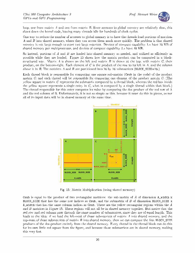
So instead, portions of A and B are loaded into shared memory as needed, and utilized as e�ciently aspossible while they are loaded. Figure 15 shows how the matrix product can be computed in a block-structured way. Matrix A is shown on the left and matrix B is shown at the top, with matrix C, theirproduct, on the bottom-right. Each element of C is the product of the row to its left in A, and the columnabove it in B. The matrices A and B are partitioned into 16 by 16 submatrices (BLOCK_SIZE=16.)
Each thread block is responsible for computing one square sub-matrix (Csub in the code) of the productmatrix C, and each thread will be responsible for computing one element of the product matrix C. (Theyellow square in matrix C represents the submatrix computed by a thread block, whereas the red box insidethe yellow square represents a single entry in C, what is computed by a single thread within that block.)The thread responsible for this entry computes its value by computing the dot product of the red row of Aand the red column of B. Unfortunately, it is not so simple as this, because it must do this in pieces, as notall of its input data will be in shared memory at the same time.
Fig. 15: Matrix Multiplication (using shared memory)
Csub is equal to the product of two rectangular matrices: the sub-matrix of A of dimension A_width xBLOCK_SIZE that has the same row indices as Csub, and the submatrix of B of dimension BLOCK_SIZE x
A_width that has the same column indices as Csub. These are the yellow rectangular regions within the Aand B matrices in Figure 15. These regions will not all be in shared memory together. But notice that thered row and red column pass through the same number of submatrices, since they are of equal length. Thisleads to the idea: if we load the left-most of those submatrices of matrix A into shared memory, and thetop-most of those submatrices of matrix B into shared memory, then we can compute the �rst BLOCK_SIZEproducts of the dot-product entirely from the shared memory. Every thread in the thread block can do thisfor its own little red square from the �gure, and because those submatrices are in shared memory, makingthis very fast.
26
CSci 360 Computer Architecture 3GPUs and GPU Programming
Prof. Stewart Weiss
When this is done, we no longer need the left-most block of A and the top-most block of B. We load fromglobal memory to shared memory the block of A to the right of the previous one, and the block of B belowthe previous one and repeat the above step. Each thread computes the dot product of the next BLOCK_SIZEentries. This gets added to the running total that the thread is maintaining for its (i,j) entry. This processcontinues until the entire row of A has been multiplied by the entire column of B. When this is �nished, theresulting square submatrix is written back to global memory.
To make the copying from global to shared memory e�cient, each thread is responsible for copying a singleelement from each of the A and B matrices. The copying is done in such a way to maximize the memorybandwidth, which will be explained within the listing below.
Listing 3: Matrix multiplication using shared memory.
// Matr ices are s to r ed in row−major order :// M( row , c o l ) = ∗(M. e lements + row ∗ M. s t r i d e + co l )// The s t r i d e o f a matrix i s the number o f bytes from the s t a r t o f a row to// the s t a r t o f the next row . The s t r i d e i s not n e c e s s a r i l y equal to the width ;// the s t r i d e can be l a r g e r so that rows are a l i gned in shared memory to// ach ieve good bandwidth .typede f s t r u c t {
i n t width ; // width o f matrixi n t he ight ; // he ight o f matrixi n t s t r i d e ; // number o f bytes from s t a r t o f row k to s t a r t o f row k+1f l o a t ∗ e lements ; // po in t e r to ac tua l matrix data
} Matrix ;
// Thread block s i z e#de f i n e BLOCK_SIZE 16
// Get the BLOCK_SIZExBLOCK_SIZE sub−matrix Msub o f M that i s// l o ca t ed co l sub−matr i ce s to the r i g h t and row sub−matr i ce s down// from the upper− l e f t corner o f M// This r e tu rn s a po in t e r to the f i r s t element o f that submatrix .__device__ Matrix GetSubMatrix (Matrix M, i n t row , i n t c o l ){
Matrix Msub ;Msub . width = BLOCK_SIZE;Msub . he ight = BLOCK_SIZE;Msub . s t r i d e = M. s t r i d e ;Msub . e lements = &M. elements [M. s t r i d e ∗ BLOCK_SIZE ∗ row
+ BLOCK_SIZE ∗ c o l ] ;r e turn Msub ;
}
// The __global__ q u a l i f i e r d e c l a r e s a func t i on as being a ke rne l .// A ke rne l i s a func t i on that i s executed on the dev i c e ( the GPU) , and// i s c a l l a b l e from the host (CPU) .// This i s a forward d e c l a r a t i on o f the dev i ce mu l t i p l i c a t i o n func t i on__global__ void Muld( f l o a t ∗ , f l o a t ∗ , int , int , f l o a t ∗ ) ;
// Host mu l t i p l i c a t i o n func t i on// Compute C = A ∗ B// height_A i s the he ight o f A// width_A i s the width o f A// width_B i s the width o f Bvoid Mult ip ly ( const f l o a t ∗A,
const f l o a t ∗B,i n t height_A ,
27
CSci 360 Computer Architecture 3GPUs and GPU Programming
Prof. Stewart Weiss
i n t width_A ,i n t width_B ,f l o a t ∗C)
{i n t s i z e ;
/∗Copy matr i ce s A and B to the dev i ce memoryTo copy r e qu i r e s us ing cudaMemCpy , which can copy e i t h e r from hostto device , from dev i ce to host , or from dev i ce to dev i c e .
∗/f l o a t ∗ A_on_device ;s i z e = height_A ∗ width_A ∗ s i z e o f ( f l o a t ) ;cudaMalloc ( ( void ∗∗)&A_on_device , s i z e ) ;cudaMemcpy(A_on_device , A, s i z e , cudaMemcpyHostToDevice ) ;
f l o a t ∗ B_on_device ;s i z e = width_A ∗ width_B ∗ s i z e o f ( f l o a t ) ;cudaMalloc ( ( void ∗∗)&B_on_device , s i z e ) ;cudaMemcpy(B_on_device , B, s i z e , cudaMemcpyHostToDevice ) ;
// A l l o ca t e matrix C on the dev i c ef l o a t ∗ C_on_device ;s i z e = height_A ∗ width_B ∗ s i z e o f ( f l o a t ) ;cudaMalloc ( ( void ∗∗)&C_on_device , s i z e ) ;
// Compute the execut ion c on f i gu r a t i on assuming// the matrix dimensions are mu l t i p l e s o f BLOCK_SIZE// The dim3 de c l a r a t i on i s used here . This s p e c i f i e s that dimBlock// i s BLOCK_SIZE x BLOCK_SIZE x 1dim3 dimBlock (BLOCK_SIZE, BLOCK_SIZE) ;
// width_B/dimBlock . x i s the l ength o f a row o f B d iv ided by the ho r i z on t a l// s i z e o f a block , which y i e l d s the number o f b locks in the ho r i z on t a l// dimension o f the Grid .// S im i l a r l y , height_A/dimBlock . y i s the he ight o f A div ided by the v e r t i c a l// s i z e o f a block , which i s the number o f b locks v e r t i c a l l y in the g r id .// These two va lue s d e f i n e the shape o f the gr id , i . e . the number o f// block h o r i z o n t a l l y and v e r t i c a l l y .dim3 dimGrid (width_B / dimBlock . x , height_A / dimBlock . y ) ;
// Launch the dev i c e computationMuld <<<dimGrid , dimBlock>>> (A_on_device ,
B_on_device ,width_A ,width_B ,C_on_device ) ;
// Copy r e s u l t C from the dev i ce to host memorycudaMemcpy(C, C_on_device , s i z e , cudaMemcpyDeviceToHost ) ;
// Free dev i ce memorycudaFree (A_on_device ) ;cudaFree (B_on_device ) ;cudaFree (C_on_device ) ;
}
28
CSci 360 Computer Architecture 3GPUs and GPU Programming
Prof. Stewart Weiss
/∗Note again the __global__ q u a l i f i e r : t h i s i s a ke rne l f unc t i onThis a l s o means that every thread execute s t h i s func t i on .When a thread execute s t h i s funct ion , i t has a s p e c i f i c thread idand block id . The thread id i s the value o f threadIdx , used below ,and the block id i s s to r ed in blockIdx , used below .threadIdx and blockIdx are each o f type dim3 .
∗/__global__void Muld( f l o a t ∗ A, f l o a t ∗ B, i n t width_A , i n t width_B , f l o a t ∗ C){
// Block indexi n t block_col = blockIdx . x ;i n t block_row = blockIdx . y ;
// Thread indexi n t thread_col = threadIdx . x ;i n t thread_row = threadIdx . y ;
// Index o f the f i r s t sub−matrix o f A proces sed by the blocki n t aBegin = width_A ∗ BLOCK_SIZE ∗ block_row ;
// Index o f the l a s t sub−matrix o f A proces sed by the blocki n t aEnd = aBegin + width_A − 1 ;
// Step s i z e used to i t e r a t e through the sub−matr i ce s o f A// The upper l e f t corner o f the next block o f A i s BLOCK_SIZE columns// from the cur rent block ' s corner , so the increment i s j u s t BLOCK_SIZE.i n t aStep = BLOCK_SIZE;
// Index o f the f i r s t sub−matrix o f B proce s sed by the blocki n t bBegin = BLOCK_SIZE ∗ block_col ;
// Step s i z e used to i t e r a t e through the sub−matr i ce s o f B// The upper l e f t corner o f the next block o f B i s BLOCK_SIZE rows// below the upper l e f t corner o f the cur rent block . Each row has// width_B bytes , so the increment i s BLOCK_SIZE ∗ width_B .i n t bStep = BLOCK_SIZE ∗ width_B ;
// The element o f the block sub−matrix that i s computed// by the threadf l o a t Csub = 0 ;
// Loop over a l l the sub−matr i ce s o f A and B requ i r ed to// compute the block sub−matrixf o r ( i n t a = aBegin , b = bBegin ;
a <= aEnd ;a += aStep , b += bStep ) {
// The __shared__ q u a l i f i e r d e c l a r e s a va r i ab l e that// ∗ r e s i d e s in the shared memory space o f a thread block ,// ∗ has the l i f e t im e o f the block , and// i s only a c c e s s i b l e from a l l the threads with in the block .// The As and Bs matr i ce s dec l a r ed below are in the shared memory o f// the block ; As i s f o r the sub−matrix o f A, and Bs , a submatrix o f B.
__shared__ f l o a t As [BLOCK_SIZE ] [BLOCK_SIZE ] ;
// Shared memory f o r the sub−matrix o f B
29
CSci 360 Computer Architecture 3GPUs and GPU Programming
Prof. Stewart Weiss
__shared__ f l o a t Bs [BLOCK_SIZE ] [BLOCK_SIZE ] ;
/∗The next s tep loads the matr i ce s from g l oba l memory to shared memory ;each thread loads one element o f each matrix .
The g l oba l memory ac c e s s by a l l threads o f a ha l f−warp i s c oa l e s c edin to one or two memory t r an s a c t i on s i f i t s a t i s f i e s the f o l l ow i n gthree cond i t i on s :
1 . Threads must a c c e s sEi ther 4−byte words , r e s u l t i n g in one 64−byte memory t ransac t i on ,Or 8−byte words , r e s u l t i n g in one 128−byte memory t ransac t i on ,Or 16−byte words , r e s u l t i n g in two 128−byte memory t r an s a c t i on s ;
2 . Al l 16 words must l i e in the same segment o f s i z e equal to thememory t r an sa c t i on s i z e ( or twice the memory t r an sa c t i on s i z ewhen a c c e s s i n g 16−byte words ) ;
3 . Threads must a c c e s s the words in sequence : The kth thread in theha l f−warp must a c c e s s the kth word .
In these i n s t r u c t i o n s , each thread i s a c c e s s i n g a 4−byte word ( f l o a t )and 16 threads do t h i s s imultaneous ly , f o r a t o t a l o f 64−bytes ineach t r an sa c t i on . The words acce s s ed by the threads are in sequenceso the ac c e s s i s c oa l e s c ed and w i l l take j u s t two t r i p s to g l oba lmemory .
∗/As [ thread_row ] [ thread_col ] = A[ a + width_A ∗ thread_row + thread_col ] ;Bs [ thread_row ] [ thread_col ] = B[ b + width_B ∗ thread_row + thread_col ] ;
// Synchronize to make sure the matr i ce s are loaded// __syncthreads ( ) i s a b a r r i e r synchron i za t i on c a l l ; a l l threads// wait here un t i l every thread has made the c a l l , at which po int i t// r e tu rn s in each thread .__syncthreads ( ) ;
/∗The loop below computes the inner product o f the row o f A_sharedand column o f B_shared as s i gned to t h i s thread , As [ thread_row ] ,and Bs [ thread_col ] , i . e . , the sum
As [ i ] [ 0 ] ∗ Bs [ 0 ] [ j ] + As [ i ] [ 1 ] ∗ Bs [ 1 ] [ j ] + . . . As [ i ] [ N−1]Bs [N−1] [ j ]
For a dev i c e with compute c ap ab i l i t y 1 . x (most dev i c e s in use todaywith CUDA capab i l i t y ) , the re are 16 banks in shared memory , each4−bytes wide . A f l o a t i s s to r ed in one word o f a bank .
Remember that a l l threads with in a s i n g l e warp execute the samei n s t r u c t i o n at a time . Therefore , when a ke rne l has a loop such as
f o r ( i n t k = 0 ; k < BLOCK_SIZE; ++k)Csub += As [ thread_row ] [ k ] ∗ Bs [ k ] [ thread_col ] ;
each thread execute s the i n s t r u c t i o n in the bosy s imu l taneous ly .
Consider that ass ignment statement ,
Csub += As [ thread_row ] [ k ] ∗ Bs [ k ] [ thread_col ] ;
f o r f i x ed k . Each o f the threads in the ha l f−warp have the samevalue o f thread_row , because a warp c o n s i s t s o f 16 threads inrow i f o l l owed by 16 threads in row i +1, f o r i = 0 , 2 , 4 , . . . 30 .
30
CSci 360 Computer Architecture 3GPUs and GPU Programming
Prof. Stewart Weiss
So the f i r s t ha l f−warp a c c e s s e s only row i , and the second ha l f−warpa c c e s s e s only row i +1.Therefore , f o r f i x e d k , As [ thread_row ] [ k ] i s the same memory l o c a t i o nand w i l l be read once and s to r ed l o c a l l y f o r each thread in ar e g i s t e r .
The va lue s Bs [ k ] [ thread_col ] are 16 s u c c e s s i v e 4−byte words , s to r edin banks 0 , 1 , 2 , . . . , 15 o f the shared memory , and t h e r e f o r e the rei s no bank c o n f l i c t in t h e i r a c c e s s i n g these banks s imulataneous ly .Therefore , by Rule 1 above , t h i s i s a 64−byte memory t r an sa c t i on thati s c oa l e s c ed in to one or two c y c l e s . In shor tthe for−loop below maximizes the shared memory bandwidth .
∗/f o r ( i n t k = 0 ; k < BLOCK_SIZE; ++k)
Csub += As [ thread_row ] [ k ] ∗ Bs [ k ] [ thread_col ] ;
// Synchronize to make sure that the preced ing// computation i s done be f o r e l oad ing two new// sub−matr i ce s o f A and B in the next i t e r a t i o n__syncthreads ( ) ;
}
// Write the block sub−matrix to g l oba l memory ;// each thread wr i t e s one elementi n t c = width_B ∗ BLOCK_SIZE ∗ block_row + BLOCK_SIZE ∗ block_col ;C[ c + width_B ∗ thread_row + thread_col ] = Csub ;
}
void in i tMat r i x ( f l o a t M[ ] , f l o a t value , i n t width , i n t he ight ){
i n t i , j ;
f o r ( i = 0 ; i < he ight ; i++ )f o r ( j = 0 ; j < width ; j++ )
M[ j + i ∗width ] = value ;}
void pr intMatr ix ( f l o a t M[ ] , i n t width , i n t he ight ){
i n t i , j ;
f o r ( i = 0 ; i < he ight ; i++ ) {f o r ( j = 0 ; j < width ; j++ )
p r i n t f ("%8.2 f " , M[ j + i ∗width ] ) ;p r i n t f ("\n " ) ;
}}
i n t main ( i n t argc , char ∗ argv [ ] ){
f l o a t ∗A, ∗B, ∗C;i n t width = MATRIXSIZE;i n t he ight = MATRIXSIZE;
A = ( f l o a t ∗) c a l l o c ( width ∗ height , s i z e o f ( f l o a t ) ) ;i f ( A == NULL )
e x i t ( 1 ) ;
31
CSci 360 Computer Architecture 3GPUs and GPU Programming
Prof. Stewart Weiss
B = ( f l o a t ∗) c a l l o c ( width ∗ height , s i z e o f ( f l o a t ) ) ;i f ( B == NULL )
e x i t ( 1 ) ;
C = ( f l o a t ∗) c a l l o c ( width ∗ height , s i z e o f ( f l o a t ) ) ;i f ( C == NULL )
e x i t ( 1 ) ;
i n i tMat r i x (A, 2 . 0 , width , he ight ) ;i n i tMat r i x (B, 3 . 0 , width , he ight ) ;i n i tMat r i x (C, 0 . 0 , width , he ight ) ;
Mult ip ly ( A, B, width , width , height , C ) ;pr intMatr ix (C, width , he ight ) ;r e turn 0 ;
}
32