gpu accelerated segmentation and centerline extraction … · gpu accelerated segmentation and...
TRANSCRIPT
Noname manuscript No.(will be inserted by the editor)
GPU Accelerated Segmentation and Centerline Extraction of TubularStructures from Medical Images
Erik Smistad · Anne C. Elster · Frank Lindseth
the date of receipt and acceptance should be inserted later
AbstractPurpose To create a fast and generic method with sufficientquality for extracting tubular structures such as blood ves-sels and airways from different modalities (CT, MR and US)and organs (brain, lungs and liver) by utilizing the computa-tional power of graphic processing units (GPUs).Methods A cropping algorithm is used to remove unnec-essary data from the datasets on the GPU. A model-basedtube detection filter combined with a new parallel center-line extraction algorithm and a parallelized region growingsegmentation algorithm is used to extract the tubular struc-tures completely on the GPU. Accuracy of the proposedGPU method and centerline algorithm is compared to theridge traversal and skeletonization/thinning methods usingsynthetic vascular datasets.Results The implementation is tested on several datasets fromthree different modalities: airways from CT, blood vesselsfrom MR and 3D Doppler Ultrasound. The results show thatthe method is able to extract airways and vessels in 3-5 sec-onds on a modern GPU and is less sensitive to noise thanother centerline extraction methods.Conclusions Tubular structures such as blood vessels andairways can be extracted from various organs imaged bydifferent modalities in a matter of seconds, even for largedatasets.
Keywords Segmentation· Centerline extraction· Vessel·Airway · GPU · Parallel
Erik Smistad· Anne C. Elster· Frank LindsethDept. of Computer and Information ScienceNorwegian University of Science and TechnologySem Saelandsvei 7-9, NO-7491 TrondheimTlf.: +47 73594475E-mail: [email protected]
Frank LindsethSINTEF Medical Technology
1 Introduction
Blood vessels and airways are both examples of impor-tant tubular structures in the human body. The extractionof these structures can be essential for planning and guid-ance of several surgical procedures such as bronchoscopy,laparoscopy and neurosurgery.
Registration is to create a mapping between two domains,for instance between an image and the patient or betweendifferent image modalities [34]. Registration is an importantstep in image guided surgery as it enables us to accuratelyplot the location of surgical tools inside the body onto im-ages of the patient using optical or magnetic tracking tech-nology. Tubular structures extracted from preoperative im-ages can be matched to similar intraoperative structures, e.g.airways generated by a tracked bronchoscope or brain ves-sels extracted from power Doppler based 3D ultrasound, andconsequently create the mapping between preoperative im-ages and the patient. Also, extracted tubular structures frompre- and intraoperative image data can be used to reduceregistration errors when a corresponding point (anatomicallandmarks or fiducials) patient registration method is used.
Furthermore, during surgical procedures, anatomical struc-tures have a tendency to move and deform inside the bodydue to respiration, pulsation, external pressure and resection.This is called anatomical shift and is a major challenge asit reduces the surgical navigation accuracy. However, it hasbeen shown that registration of blood vessels from pre- andintraoperative image data can be used to detect and correctorganshift such as brainshift [38].
The automatic extraction of tubular structures can bevery time consuming. As time during surgery is very crucial,long-lasting processing should be avoided. Preoperative data
This is a preprint. The final publication is available atlink.springer.com
2 Erik Smistad et al.
is often acquired just before the procedure and thus it is de-sirable to process these data as fast as possible as well. Thepurpose of this work is to create a fast and generic methodwith sufficient quality for extracting tubular structures suchas blood vessels and airways from different modalities (CT,MR and US) and organs (brain, lungs, liver) by utilizing thecomputational power of graphic processing units (GPUs).
The rest of the introduction discuss GPU computing andprovides a brief survey of existing methods for extractingtubular structures from medical images. An overview of thecontributions in this paper is also given. The methodologysection provides a detailed description of each part of the im-plementation including how it is optimized for the GPU andevaluated. In the result section, performance is measured interms of speed and quality. Finally, the results are discussedand conclusions are given.
1.1 GPU computing
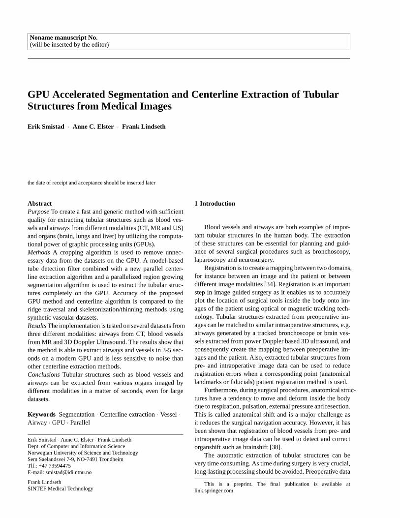
Several image processing techniques are data parallel be-cause each pixel can be processed in parallel using the sameinstructions. Graphic Processing Units (GPUs) allow manypixels/voxels to be processed in the same clock cycle, en-abling substantial speedups. The GPU is a type of singleinstruction, multiple data (SIMD) processor. It can performthe same instruction on each element in a dataset in paral-lel. This is achieved by having many functional units likearithmetic-logic units (ALUs) that share a control unit. Fig.1 depicts the general layout of a GPU and its memory hi-erarchy. The GPU originally had a fixed pipeline that wascreated for fast rendering of 3D graphics. The introductionof programmable shaders in the pipeline made it possible torun programs on the GPU. However, the task of program-ming shaders to solve arbitrary problems requires knowl-edge about the GPU pipeline as the problem at hand needsto be transformed into a rendering problem. General pur-pose GPU (GPGPU) programming languages and frame-works such as CUDA and OpenCL were created to makeGPU programming easier. The field of GPU computing isstill young. However, a brief survey of medical image pro-cessing and visualization on the GPU was recently providedby Shi et al. [39].
1.2 Methods for extracting tubular structures
Tubular structures are usually extracted from volumes in twodifferent ways:
– As asegmentation, either as a binary classification whereeach voxel in the volume is given a non-zero value if itbelongs to the tubular structure or as a surface model ofthe structure.
Fig. 1 General architecture of a GPU and its memory hierarchy. Notehowever, that the actual architecture is much more complex and differfor each GPU. This diagram only shows the general features.
– As a centerline, i.e. a line that goes through the centerof the tubular structures.
Both representations are useful in different applications.For instance, the centerline is very useful for registrationwhile the segmentation is useful for volume estimation andvisualization of the structures’ surface.
There exist several methods for extracting tubular struc-tures from medical images. A recent and extensive reviewon blood vessel extraction was done by Lesage et al. [29]and an older one by Kirbas and Quek [25]. Two reviews onthe segmentation of airways were done by Lo et al. [31] andSluimer et al. [40].
A common method for extracting tubular structures isto grow the segmentation iteratively from an initial point orarea using methods such as region growing [27,45,16], ac-tive contours and wave front propagation (e.g. snakes andlevel sets) [24,35,46,32]. A centerline can then be extractedfrom the segmentation using skeletonization and 3D thin-ning methods [28,18,22].
Growing a segmentation using only a model of desiredintensity values has shown to give limited result in severalapplications such as airway segmentation where the thin air-way walls may cause severe segmentation leakage [32]. Thusin many applications it may be necessary to use a model ofthe shape of the tubular structures as well. Also, these grow-ing methods are very sensitive to initialization.
Tube Detection Filters (TDFs) are used to detect tubularstructures and calculates a probability that a specific voxel

GPU Accelerated Segmentation and Centerline Extraction of Tubular Structures from Medical Images 3
is inside a tubular structure. Most TDFs use gradient infor-mation, often in the form of an eigenanalysis of the Hessianmatrix. Frangi et al. [15] presented an enhancement and de-tection method for tubular structures based on the eigenval-ues of this matrix. Krissian et al. [26] created a model-baseddetection filter that fits a circle to the cross-sectional planeof the tubular structure defined by the eigenvectors of theHessian.
A centerline can be extracted directly from the TDF re-sult without a segmentation using methods such as ridgetraversal. Aylward et al. [2] provides a review of differentcenterline extraction methods and proposed an improved ridgetraversal algorithm based on a set of ridge criteria and differ-ent methods for handling noise. Bauer et al. [6] showed howthis method could be used together with Gradient VectorFlow. For applications where only the centerline is needed,segmentation can be skipped using this method and thus re-duce processing time.
Some related work on accelerating the extraction of tubu-lar structures on the GPU exist. Erdt et al. [14] performed theTDF and a region growing segmentation on the GPU and re-ported a 15 times faster computation of the gradients and upto 100 times faster TDF. Narayanaswamy et al. [36] did ves-sel luminae region growing segmentation on the GPU andreported a speedup of 8. Bauer et al. presented a GPU accel-eration for airway segmentation by doing the Gradient Vec-tor Flow computation on the GPU in [7] and the TDF calcu-lation on the GPU in [8]. However, they only provide a lim-ited description of the GPU implementations. Helmbergeret al. performed region growing for airway segmentation onthe GPU and a lung vessel segmentation on the GPU usinga TDF [21]. They reported a runtime of 5-10 minutes usinga modern GPU and CUDA compared to a runtime of up toan hour using only the CPU.
1.3 Contributions
The methodology in this paper is inspired by the works ofBauer et al. [7,3,8] and Krissian et al. [26] and is a con-tinuation of our previous paper on GPU accelerated airwaysegmentation [41].
The main contributions in this paper are:
– A fast and generic method that can extract tubular struc-tures like blood vessels and airways from different modal-ities (e.g. CT, MR and Ultrasound) and organs (e.g. lung,brain and liver) entirely on the GPU.
– A new parallel GPU algorithm for extracting centerlinesdirectly from the TDF result.
– A generic parallel cropping algorithm for reducing mem-ory usage on the GPU.
2 Methodology
The implementation is written in C++ and OpenCL and isavailable online. OpenCL is a framework for running paral-lel programs on heterogeneous platforms such as CPU andGPU. The implementation consists of five main steps thatare all executed on the GPU (see Fig. 2).
Fig. 2 Block diagram of the implementation
The first step is to crop the volume in order to reducethe total memory usage. The second step involves a few pre-processing steps such as Gaussian smoothing and GradientVector Flow which are necessary to make the results lesssensitive to noise and differences in tube contrast and size.After pre-processing, the model-based TDF by Krissian etal. [26] is used. From the TDF result, the centerlines areextracted using a new parallel algorithm. Finally, a segmen-tation is performed using the centerlines as seeds for a re-gion growing procedure. However, if only the centerlines areneeded for a given application, the segmentation step can beskipped. The rest of this section will describe each of thefive steps in further detail.
2.1 Cropping
Memory on the GPU is limited and may not be enough forprocessing large datasets. However, most medical datasets
http://github.com/smistad/Tube-Segmentation-Framework/
4 Erik Smistad et al.
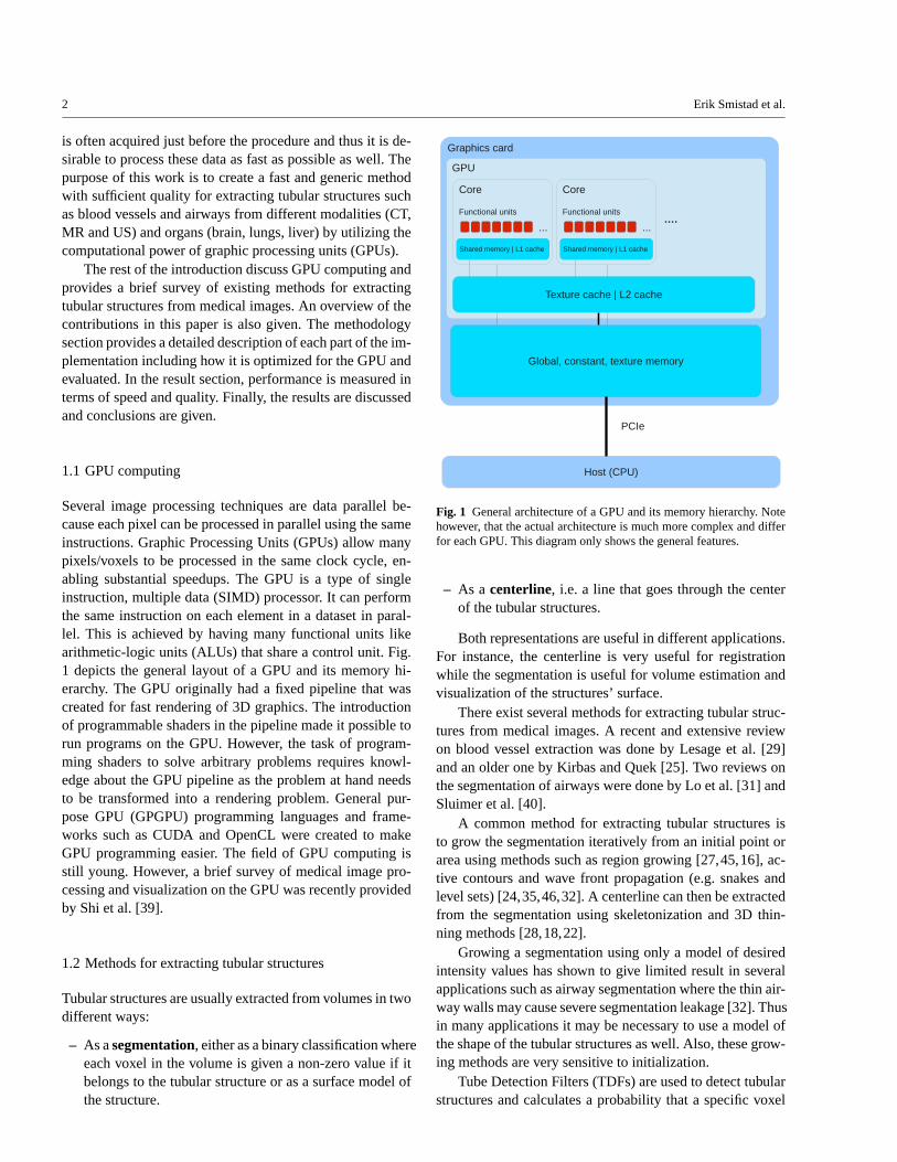
contain a lot of data that is not part of the structures of in-terest. Usually these areas are located at the borders of theimage. For instance, in the thorax CT image in Fig. 3, the ac-tual lungs where the airways and blood vessels are located,constitutes only about 50% of the image. The rest consist ofspace outside the body, body fat and the bench that the pa-tient is resting on. As several of the methods used to performsegmentation and centerline extraction process each voxelinthe entire volume, removing the unnecessary data will notonly reduce memory usage, but also execution time.
In our previous work [41], we presented a novel crop-ping algorithm for airway segmentation that could be run inparallel on the GPU using less than half a second for largeCT volumes of the lungs. In this paper, this algorithm is ex-tended to crop other medical datasets, such as MR and 3DDoppler Ultrasound. The cropping method works by consid-ering slices in all three orthogonal directions x, y and z. Foreach slices, the method determines if the slice intersects theregion of interest (ROI). This is done by counting the num-ber of rows in the slice that intersects the ROI for each sliceand storing it asLs. If Ls > Lmin, the slice is considered tohave intersected the ROI. The cropping borders are found bytraversing throughLs twice froms= 0 ands= size and find-ing the first slice that has a value above a specific thresholdLmin. These slices are then selected as cropping bordersc1
andc2. This is done for each direction and results in 3 pairsof cropping borders which is all that is needed to crop thevolume. An example of how this cropping procedure worksis shown in Fig. 3. For some applications and directions itmay be necessary to start the search from the middles = size
2to the end instead. This was the case for the axial directionof CT airway datasets.
Algorithm 1 provides pseudocode for the cropping method.The functionCALCULATEL is used for estimatingL for eachslice in a given direction and the functionFINDCROPBOR-DERS is used to find the cropping borders for a specific di-rection givenL and using the thresholdLmin. Each directionand slice can be processed in parallel on the GPU. For adataset of size 512x512x512 this results in 3*512 individualthreads that can be processed using the same instructions.
The parts of this cropping method that is application de-pendent, aside from the parameterLmin, is the estimation ofLs and whether the search for cropping borders starts fromthe middle or at the ends of the dataset in a given direction.
For MR and 3D Doppler Ultrasound images it is suffi-cient to remove the background from the dataset. For thispurposeLs can be estimated by counting the number of vox-elsnv on a scan line that is above a certain thresholdIT . Ls
is then set to the number of rows in slices wherenv > IT . Athreshold value of 100 was found to be enough for the MRand Ultrasound datasets.
For CT images of the lungs, fat and other tissue that arenot part of the lungs can also be discarded by counting the
Fig. 3 Example of the cropping procedure. The black arrows indicateslices that haveLs > Lmin and thus intersected the ROI while the greyarrows are the opposite. This can be used to find the cropping borders,marked with dotted red lines in the figure. This is done in all threedirections and each slice is processed in parallel.
number of areas that are above and below a certain thresh-old. Details on this estimation ofLs can be found in our pre-vious work [41].
2.2 Pre-processing and Gradient Vector Flow
Before the actual tube extraction, some pre-processing isnecessary. First, an optional thresholding is performed onthe dataset using a lower and upper threshold (Imin andImax).Thresholding may be necessary for datasets which have alarge range of intensity values such as CT images. The thresh-olding is done to remove unnecessary gradient informationin the image which may lead to unwanted tubular structuresbeing detected. For instance, when extracting airways allintensities above -500 HU can be converted to -500 as noairways have intensity above this threshold. Second, somenoise suppression is performed. This is done by blurring thedataset using Gaussian smoothing with standard deviationσ . Afterwards, the gradient vector fieldV is created and nor-malized using a parameter calledVmax. All gradients with alength above this parameter will be set to unit length andthe others will be scaled accordingly. The gradient normal-ization is necessary for contrast invariance.Vmax should beadapted to the expected level of contrast and noise. Also, ifblack tubular structures are to be extracted (e.g. airways),
GPU Accelerated Segmentation and Centerline Extraction of Tubular Structures from Medical Images 5
Algorithm 1 Croppingfunction CROP(volume)
L ← CALCULATEL(volume, x)x1,x2← FINDCROPBORDERS(L, x)L ← CALCULATEL(volume, y)y1,y2← FINDCROPBORDERS(L, y)L ← CALCULATEL(volume, z)z1,z2← FINDCROPBORDERS(L, z)crop volume according to x1,x2,y1,y2,z1 and z2return volume
end function
function CALCULATEL(volume, direction)for each slice s in direction in paralleldo
EstimateLs
end forreturn L
end function
function FINDCROPBORDERS(L, direction)size← volume.direction.sizec1←−1,c2←−1,s← 0while (c1 =−1 or c2 =−1) and s < size do
if Ls > Lmin and c1 =−1 thenc1← s
end ifif Lsize−1−s > Lmin and c2 =−1 then
c2← size−1− send ifs← s+1
end whilereturn c1,c2
end function
the gradients have to invertedV = −∇I. All of these pre-processing parameters (Imin, Imax, σ , Vmax) are modality de-pendent and the values used in this paper for each modalityis collected in Table 1.
Filters that use the Hessian matrix to detect tubular struc-tures require gradient information to be present in the centerof the tube. For large tubes, such astrachea and the mainbronchi, the gradient information will not exist in the center.Thus, it is necessary to propagate the gradient informationfrom the tube edge to the center. There exist two main meth-ods of doing this: Gaussian scale space and Gradient VectorFlow (GVF). Xu et al. [47] originally introduced GVF asan external force field for active contours. Bauer et al. [5,3] were the first to show that GVF could be used to createscale-invariance of TDFs. The GVF method has the advan-tage that it is feature-preserving and thus can avoid the prob-lem of several structures diffusing into each other to createthe illusion of a tubular structure at a higher scale. Also,GVF is only calculated using one scale. However, it has thedisadvantage that it is very computationally expensive. Nev-ertheless, it has been shown that GVF can be acceleratedusing GPUs. Eidheim et al. [13], He and Kuester [20] andZheng and Zhang [48] all presented a GPU implementationof GVF and Active Contours using shader languages. How-
ever, their implementation was for 2D images only. In thispaper, a highly optimized 3D GPU implementation of GVFfrom Smistad et al. [42] was used with a predefined num-ber of 250 iterations. This implementation allows GVF tobe calculated for large volumes in only a few seconds.
2.3 Tube Detection Filter
Krissian et al. [26] created a TDF that assumes that the cross-section of the tubular structure is circular. Their TDF calcu-lates how well a circle match the gradient information in thecross-sectional plane defined by the eigenvectors of the Hes-sian matrix. The TDF starts by creating a circle with a smallradius in the cross-sectional plane.N = 32 evenly spacedpoints on the circle is sampled from the vector field. Eachpoint, i, is found by calculating its angleα from the centerand then calculating a vectordi which lies in the plane andhas angleα.
α =2πiN
(1)
di = e2sinα +e3cosα (2)
The position of pointi on a circle with radiusr and cen-ter v is then given asv+ rdi. How well the circle match thegradient information is calculated as the average dot prod-uct of the gradient at positioni and the inward normal of thecircle at pointi which is equal to−di. The TDF of Krissianet al. [26] is shown in equation 3. The radius of the circle isincreased with 0.5 voxels as long as the average dot productalso increases.
T (v,r,N) =1N
N−1
∑i=0
V(v+ rdi) ·−di (3)
As noted by Bauer et al. [7,3], the GVF method mayeliminate the gradient information for small low-contrasttubu-lar structures. Thus to detect these tubular structures it isnecessary to run the TDF two times. Once with a smallradius on the initial vector field to detect the small low-contrast structures and once with the GVF vector field to de-tect the rest. Different amounts of Gaussian blur can be usedfor the tube detection of large and small structures (σsmall
andσlarge as seen in Table 1). The TDF response from eachof these are combined by selecting the largest TDF value foreach voxel.
2.4 Centerline Extraction
Centerline extraction from TDF results has primarily beendone by ridge traversal [2,4,6,5]. One problem with the ridgetraversal procedure is that it can’t be run in parallel. Thus,

6 Erik Smistad et al.
Fig. 4 Determining the angleθ from a centerpointx to its neighborn.
the GVF vector field and the TDF result has to be transferredto the CPU. Nevertheless, the serial ridge traversal algorithmcan be used together with the rest of the GPU algorithmspresented in this paper (e.g. cropping, pre-processing, tubedetection and segmentation).
In this section, a new parallel centerline extraction (PCE)algorithm is presented. This centerline algorithm, unlikeridgetraversal, can be run efficiently in parallel on a GPU. Themethod has 4 main steps: Identifying centerpoints, filteringcenterpoints, link centerpoints and centerline selection.
2.4.1 Identify candidate centerpoints
The method for extracting centerlines starts by identifyingall possible centerpoints. This is done by creating a 3D struc-ture with the same size as the dataset. This structure is ini-tialized to 0 for each voxel and all voxels with a TDF valueabove the thresholdTc = 0.5 is set to 1.
2.4.2 Filter centerpoints
The next step removes centerpoints that are either not in thecenter of a tube or too close to other centerpoints. Whether acenterpoint is in the center of a tube or not can be determinedby the magnitude of the GVF vector field|V|, because|V| issmallest in the center of the tube.
First, a vector from the centerpointx to a neighbor voxeln is calculated:
r = n−x (4)
Second, this vector is projected onto the cross-sectional planeof the tube (see Fig. 4). The plane’s normale1 is the eigen-vector of the Hessian matrix associated with the eigenvalueof smallest magnitude. This vector points in the direction ofthe tube.
r p = r −e1(e1 · r) (5)
Finally, the angleθ from the plane to the vectorr can becalculated using the projected vectorr p:
θ = cos−1(
r · r p
|r ||r p|
)
(6)
Let N be the set of all neighbor voxels that are close(|r | < r, wherer is from Eq. 3) and the angle isθ < 30◦.For each of thesen, the magnitude of the GVF vector field|V| is compared to the centerpointx. The centerpoint is onlyvalid if the magnitude for the centerpointx is lower than alln ∈ N:
C(x) ={
1 if ∀n ∈ N |V(n)|> |V(x)|0 else
(7)
This has the effect that it removes centerpoints that arenot in the center of a tubular structure.
The next step is to remove centerpoints that are too closeto each other. The reason for doing this is that it reducesthe total number of centerpoints and thus makes the nextstep, linking the centerpoints, much more efficient. Remov-ing points that are too close to each other is done by dividingthe entire dataset into a grid with each grid element spanning4x4x4 voxels. For each cube in the grid, the best centerpointis selected and the rest of the centerpoints in that cube isremoved. The centerpoint with the highest TDF value is se-lected as the best centerpoint in a cube.
2.4.3 Link centerpoints
For each centerpoint, the method establishes links betweenthe centerpoints to create centerlines. This is done by con-necting each centerpoint to the two centerpoints that are clos-est and fulfills the following criteria:
– The angle between them is above 120 degrees.– The average TDF value along the line is higher than
Tmean= 0.5.
2.4.4 Centerline selection
Due to noise and other image artifacts invalid centerpointsand centerlines may be created. However, these are usu-ally short and not connected to the actual tubular structures.Thus invalid centerlines can often be discarded based ontheir length.
In this step, all centerpoints that are connected with cen-terlines from the previous section are assigned the same la-bel. Those that are not connected get different labels. Graphcomponent labeling is the problem of finding and labelingnodes in a graph that are connected. Hawick et al. [19] pre-sented several GPU implementations of algorithms for graphcomponent labeling. In our implementation, an iterative methodusing atomic operations was used. AssumingN labels,N
GPU Accelerated Segmentation and Centerline Extraction of Tubular Structures from Medical Images 7
counters are created and initialized to 0. A kernel is executedfor each centerpoint and the length of each centerline, iden-tified with a label, is determined by using an atomic incre-ment operation on the counter identified by the centerpoints’labels. After the execution of this kernel, the counters willcontain the total length of each centerline. When the lengthof all connected centerlines have been calculated, the largestcenterline or all centerlines with a specified minimum lengthcan be extracted.
2.5 Segmentation
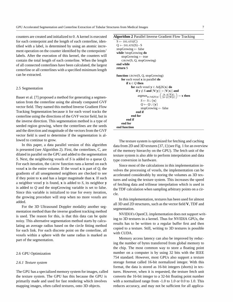
Bauer et al. [7] proposed a method for generating a segmen-tation from the centerline using the already computed GVFvector field. They named this method Inverse Gradient FlowTracking Segmentation because it for each voxel tracks thecenterline using the directions of the GVF vector field, but inthe inverse direction. This segmentation method is a type ofseeded region growing, where the centerlines are the seedsand the direction and magnitude of the vectors from the GVFvector field is used to determine if the segmentation is al-lowed to continue to grow.
In this paper, a data parallel version of this algorithmis presented (see Algorithm 2). First, the centerlines, C, aredilated in parallel on the GPU and added to the segmentationS. Next, the neighboring voxels ofS is added to a queueQ.For each iteration, theGROW function runs a kernel on eachvoxel x in the entire volume. If the voxelx is part ofQ, thegradients of all unsegmented neighbors are checked to seeif they point tox and has a larger magnitude thanx. If sucha neighbor voxely is found,x is added toS, its neighboryis added toQ and the stopGrowing variable is set to false.Since this variable is initialized to true for every iteration,the growing procedure will stop when no more voxels areadded.
For the 3D Ultrasound Doppler modality another seg-mentation method than the inverse gradient tracking methodis used. The reason for this, is that this data can be quitenoisy. This alternative segmentation method starts by calcu-lating an average radius based on the circle fitting methodfor each link. For each discrete point on the centerline, allvoxels within a sphere with the same radius is marked aspart of the segmentation.
2.6 GPU Optimization
2.6.1 Texture system
The GPU has a specialized memory system for images, calledthe texture system. The GPU has this because the GPU isprimarily made and used for fast rendering which involvesmapping images, often called textures, onto 3D objects.
Algorithm 2 Parallel Inverse Gradient Flow TrackingS← DILATE (C)Q← DILATE (S) - SstopGrowing← falsewhile !stopGrowingdo
stopGrowing← trueGROW(S, Q, stopGrowing)
end whilereturn S
function GROW(S, Q, stopGrowing)for each voxelx in paralleldo
if x ∈ Q thenfor each voxely ∈ Adj26(x) do
if y /∈ S and |V(y)|> |V(x)| and
argmaxz∈Adj26(y)
(
(z−y)·V(y)|(z−y)||V(y)|
)
= x then
S← S∪{x}Q← Q∪{y}stopGrowing← false
end ifend for
end ifend for
end function
The texture system is optimized for fetching and cachingdata from 2D and 3D textures [37,1] (see Fig. 1 for an overviewof the memory hierarchy on the GPU). The fetch unit of thetexture system is also able to perform interpolation and datatype conversion in hardware.
Since most of the calculations in this implementation in-volves the processing of voxels, the implementation can beaccelerated considerably by storing the volumes as 3D tex-tures and using the texture system. This increases the speedof fetching data and trilinear interpolation which is used inthe TDF calculation when sampling arbitrary points on a cir-cle.
In this implementation, textures has been used for almostall 3D and 2D structures, such as the vector fieldV, TDF andsegmentation.
NVIDIA’s OpenCL implementation does not support writ-ing to 3D textures in a kernel. Thus for NVIDIA GPUs, theresults has to be written to a regular buffer first and thencopied to a texture. Still, writing to 3D textures is possiblewith CUDA.
Memory access latency can also be improved by reduc-ing the number of bytes transferred from global memory tothe chip. The most common way to store a floating pointnumber on a computer is by using 32 bits with the IEEE754 standard. However, most GPUs also support a texturestorage format called 16-bit normalized integer. With thisformat, the data is stored as 16-bit integers (shorts) in tex-tures. However, when it is requested, the texture fetch unitconverts the 16-bit integer to a 32-bit floating point numberwith a normalized range from -1.0 to 1.0 or 0.0 to 1.0. Thisreduces accuracy, and may not be sufficient for all applica-
8 Erik Smistad et al.
tions. However, it was found to be sufficient for this applica-tion (see result section). This storage format also halves theglobal memory usage, thus allowing much larger volumes tofit in the limited GPU memory. In our recent work on opti-mizing GVF for GPU execution [42], it was discovered thatusing textures and the 16-bit format could make the parallelexecution a lot faster, depending on the size of the datasetbeing processed. In this implementation, the 16-bit normal-ized integer format is used for the dataset, vector fields andTDF result.
2.6.2 Stream compaction
After finding the candidate centerpoints, we only want toprocess these points in the next centerpoint filtering step.This can be done by launching a kernel for every voxel inthe volume and have an if statement checking whether thevoxel is a candidate centerpoint. However, this can be veryinefficient on a GPU. As explained in the introduction, thefunctional units on the GPU are grouped together and sharea control unit. This means that the functional units in a grouphave to execute the same instructions in each clock cycle. Toensure that the correct result is generated by if statements,the GPU will use masking techniques. Nevertheless, such anif statement may not reduce the processing time as it wouldif it was executed sequentially on a CPU. On a GPU, it mighteven increase the processing time due to the need of maskingtechniques to ensure correct results. This is a common prob-lem in GPU computing and one solution is a method calledstream compaction. Stream compaction removes voxels thatshould not be processed from the volume so that the ker-nel is only run for the valid voxels, thus no if statement isneeded. Stream compaction can be done on the GPU withlogarithmic time complexity. Two methods for performingstream compaction is parallel prefix sum (see Billeter et al.[11] for an overview) and Histogram Pyramids by Ziegleret al. [49]. In this work, Histogram Pyramids has been useddue to the fact that this data structure has shown to be betterin some applications by exploiting the GPU’s texture sys-tem for faster memory access. The original implementationby Ziegler et al. [49] was for 2D. However, in our previouswork [43], we presented a 3D version of this stream com-paction algorithm which also reduced the memory usage forthis data structure.
The Histogram Pyramid stream compaction method hasbeen used in three places of this implementation. All in thecenterline extraction step. The 3D Histogram Pyramid isused after the candidate centerpoint step and filter center-points step. A 2D Histogram Pyramid is used after the linkcenterpoints step, where each link is stored in an adjacencymatrix on the GPU.
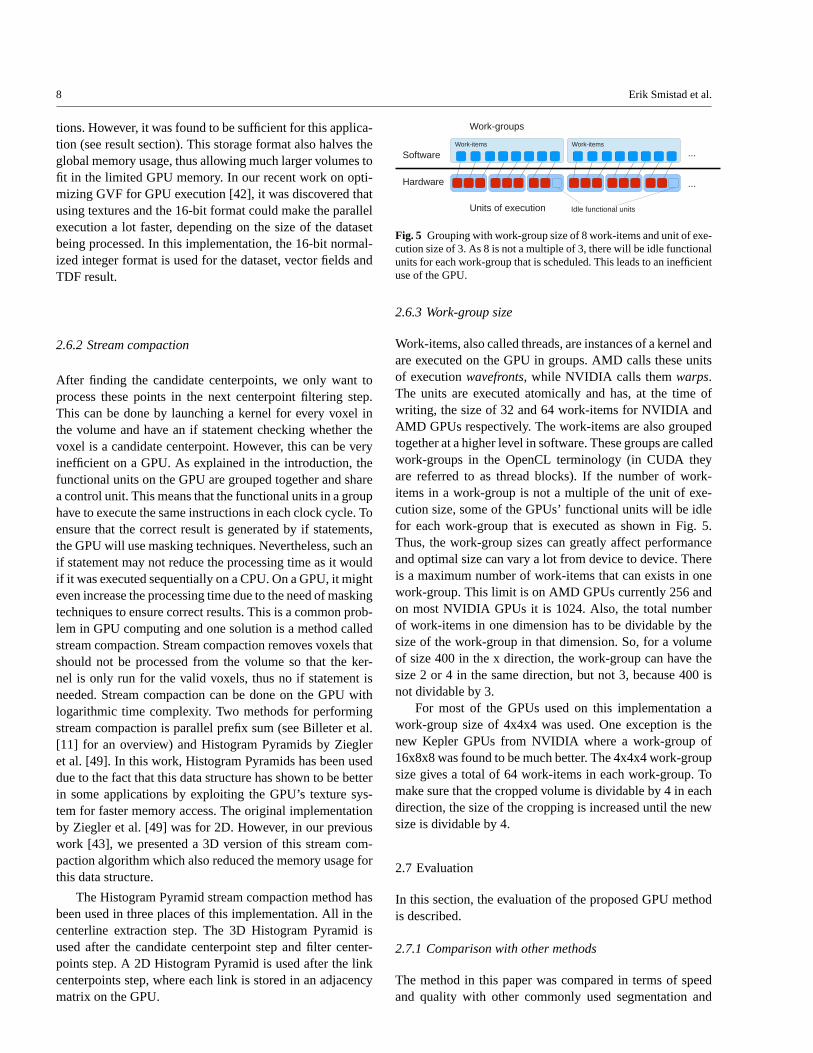
Fig. 5 Grouping with work-group size of 8 work-items and unit of exe-cution size of 3. As 8 is not a multiple of 3, there will be idle functionalunits for each work-group that is scheduled. This leads to an inefficientuse of the GPU.
2.6.3 Work-group size
Work-items, also called threads, are instances of a kernel andare executed on the GPU in groups. AMD calls these unitsof executionwavefronts, while NVIDIA calls themwarps.The units are executed atomically and has, at the time ofwriting, the size of 32 and 64 work-items for NVIDIA andAMD GPUs respectively. The work-items are also groupedtogether at a higher level in software. These groups are calledwork-groups in the OpenCL terminology (in CUDA theyare referred to as thread blocks). If the number of work-items in a work-group is not a multiple of the unit of exe-cution size, some of the GPUs’ functional units will be idlefor each work-group that is executed as shown in Fig. 5.Thus, the work-group sizes can greatly affect performanceand optimal size can vary a lot from device to device. Thereis a maximum number of work-items that can exists in onework-group. This limit is on AMD GPUs currently 256 andon most NVIDIA GPUs it is 1024. Also, the total numberof work-items in one dimension has to be dividable by thesize of the work-group in that dimension. So, for a volumeof size 400 in the x direction, the work-group can have thesize 2 or 4 in the same direction, but not 3, because 400 isnot dividable by 3.
For most of the GPUs used on this implementation awork-group size of 4x4x4 was used. One exception is thenew Kepler GPUs from NVIDIA where a work-group of16x8x8 was found to be much better. The 4x4x4 work-groupsize gives a total of 64 work-items in each work-group. Tomake sure that the cropped volume is dividable by 4 in eachdirection, the size of the cropping is increased until the newsize is dividable by 4.
2.7 Evaluation
In this section, the evaluation of the proposed GPU methodis described.
2.7.1 Comparison with other methods
The method in this paper was compared in terms of speedand quality with other commonly used segmentation and
GPU Accelerated Segmentation and Centerline Extraction of Tubular Structures from Medical Images 9
centerline extraction algorithms. Blood vessels from the MRAngio, Doppler Ultrasound and synthetic datasets were seg-mented using thresholding after performing Gaussian blur.As thresholding is unsuitable for segmenting airways, an im-plementation of region growing, similar to the conservativeregion growing used in Graham et al. [16], was used instead.This region growing methods starts by automatically findinga seed point insidetrachea. This is done by looking for adark circular region in the middle of one of the upper slices.After a seed has been found, the dataset is filtered with aGaussian mask withσ = 0.5 voxels and the intensities arecapped at -500 HU as no airways have intensities above thisthreshold. Next, a region growing procedure with segmen-tation leakage detection is used. The region growing is per-formed several times with increasing threshold starting withthe intensity of the seed. For each iteration, the volume sizeis measured. If the volume size increases with more than 20000 voxels in one iteration a segmentation leakage has mostlikely occurred and the previous threshold is used. Finally,a morphological closing is performed to remove any holesinside the segmentation.
The proposed GPU implementation can be used togetherwith both the PCE algorithm and the ridge traversal algo-rithm for the centerline extraction step. Thus, with the serialridge traversal algorithm a hybrid solution is used where allsteps except the centerline extraction step is run on the GPU.
For the centerline extraction, the proposed GPU methodis evaluated with both the proposed PCE centerline algo-rithm and the ridge traversal algorithm and compared to anITK filter by Homann [22] based on the skeletonization al-gorithm by Lee et al. [28]. This skeletonization method per-forms iterative thinning of a segmented volume. Note thatthe implementation by Homann [22] does not exploit paral-lelism.
2.7.2 Qualitative analysis
To show the general applicability of the method, clinical im-ages from three different modalities and two different organswere used:
1. Computer Tomography scans of the lungs (Airways, 12datasets)
2. Magnetic Resonance images of the brain (Blood vessels,4 datasets)
3. 3D Ultrasound Doppler images of the brain (Blood ves-sels, 7 datasets)
The study was approved by the local ethics committee, andthe patients gave informed consent prior to the procedure.For each modality, several datasets were processed using theproposed GPU implementation together with the PCE andthe ridge traversal centerline algorithms and region growing/ thresholding together with skeletonization.
Note that for each modality the same parameters wereused, except for a small set of modality dependent parame-ters such as blur and radius (see Table 1).
2.7.3 Speed and memory usage
The speed of the method was measured on all the clinicaldatasets using three different GPUs from both AMD andNVIDIA. Two high-end GPUs with a peak performance ofaround 4 tera floating point operations per second (TFLOPS)(AMD HD7970 and NVIDIA Tesla K20). And one GPU ofthe previous generation with a peak performance of about 1TFLOPS (NVIDIA Tesla C2070). The implementation wasrun using both 16-bit normalized integers and 32-bit floatingpoint vectors to see how the two different data types affectedthe speed. The proposed method was also run on an Intel i7-3770 CPU (4 cores, 3.4 GHz) with 16 GB memory to showthe speedup of using a GPU versus a multi-core CPU. Thiswas also done to demonstrate that the proposed implemen-tation can be run in parallel on a multi-core CPU with nomodification.
For comparison, runtime measurements for region grow-ing, thresholding and skeletonization were performed foreach modality using an Intel i7-3770 CPU with 4 cores run-ning at 3.4 GHz. Parts of the region growing and threshold-ing methods were parallelized using OpenMP.
As explained earlier, the memory available on GPUs islimited. Thus it is important to keep the memory usage aslow as possible. In this paper, a cropping procedure and a16-bit normalized integer data format was used to reducethe memory usage on the GPU. To show the effect of thecropping procedure, the average dataset size and peak mem-ory usage before and after cropping was measured on sev-eral datasets from different modalities. Peak memory us-age occurs in the Gradient Vector Flow step. In this step,3 vector fields with 3 components, each of the same sizeas the dataset are needed. For an uncropped volume of size512x512x800 and 32-bit floats this amounts to 3∗ 3∗ 4∗512∗ 512∗ 800 bytes = 7200 MB. When using 16-bit nor-malized integers the memory usage is halved.
2.7.4 Quantitative analysis
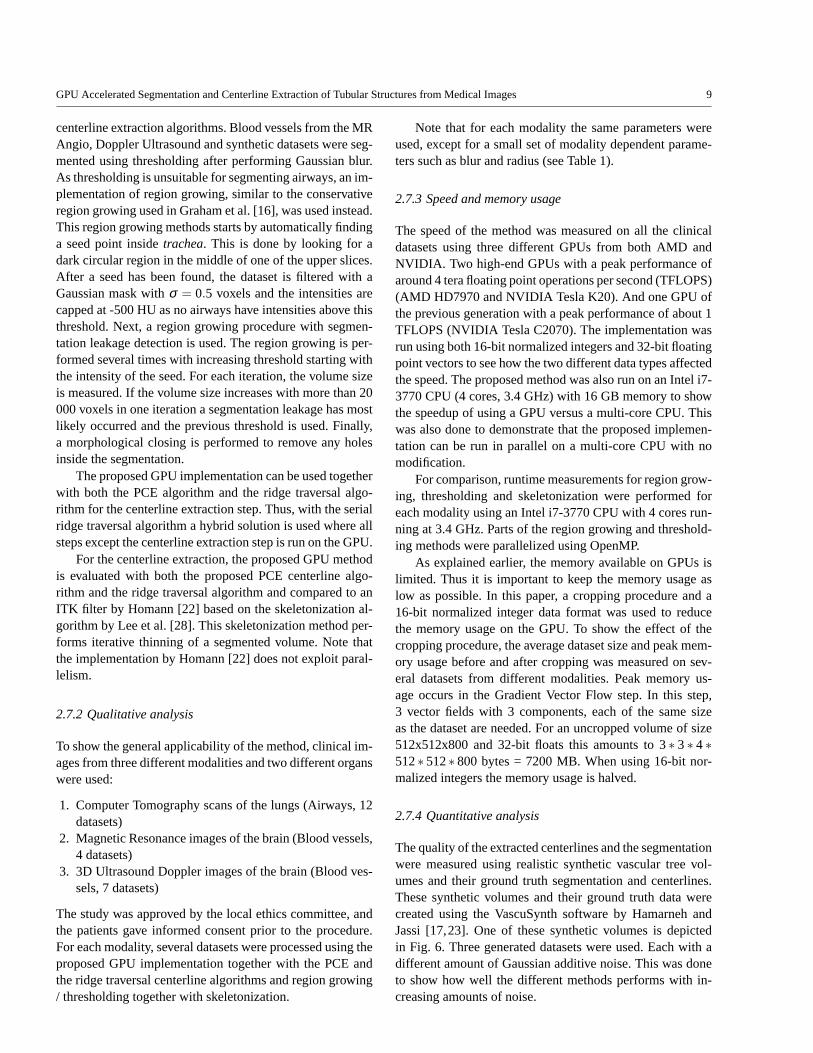
The quality of the extracted centerlines and the segmentationwere measured using realistic synthetic vascular tree vol-umes and their ground truth segmentation and centerlines.These synthetic volumes and their ground truth data werecreated using the VascuSynth software by Hamarneh andJassi [17,23]. One of these synthetic volumes is depictedin Fig. 6. Three generated datasets were used. Each with adifferent amount of Gaussian additive noise. This was doneto show how well the different methods performs with in-creasing amounts of noise.
10 Erik Smistad et al.
Fig. 6 Synthetic vascular image created using the VascuSynth softwareby Hamarneh and Jassi [17,23].
Each discrete point of the centerline is called a center-point. The accuracy of the centerline was measured usingthe Hausdorff distance measure which is the average dis-tance from each centerpoint of the extracted centerline to theclosest point on the ground truth centerline. To estimate howmuch of the vascular tree was extracted, each extracted pointmarks all ground truth centerpoints within a radius of 4 vox-els as detected. The total percentage extracted is then calcu-lated as the number of detected points divided by the totalnumber of ground truth centerpoints. Any extracted center-point that was farther away than 4 voxels from a grouth truthcenterpoint was marked as invalid. The parameters for theamount of Gaussian blur andVmax were adjusted for eachdataset and centerline method so that no extracted center-points were marked as invalid. Precision and recall for thesegmentation is calculated by comparing each voxel of thesegmentation result to the ground truth.
The quantitative analysis was performed using the pro-posed GPU implementation with both PCE and ridge traver-sal and thresholding+skeletonization together with 16-bit nor-malized integers and 32-bit floating point numbers.
3 Results
3.1 Qualitative analysis
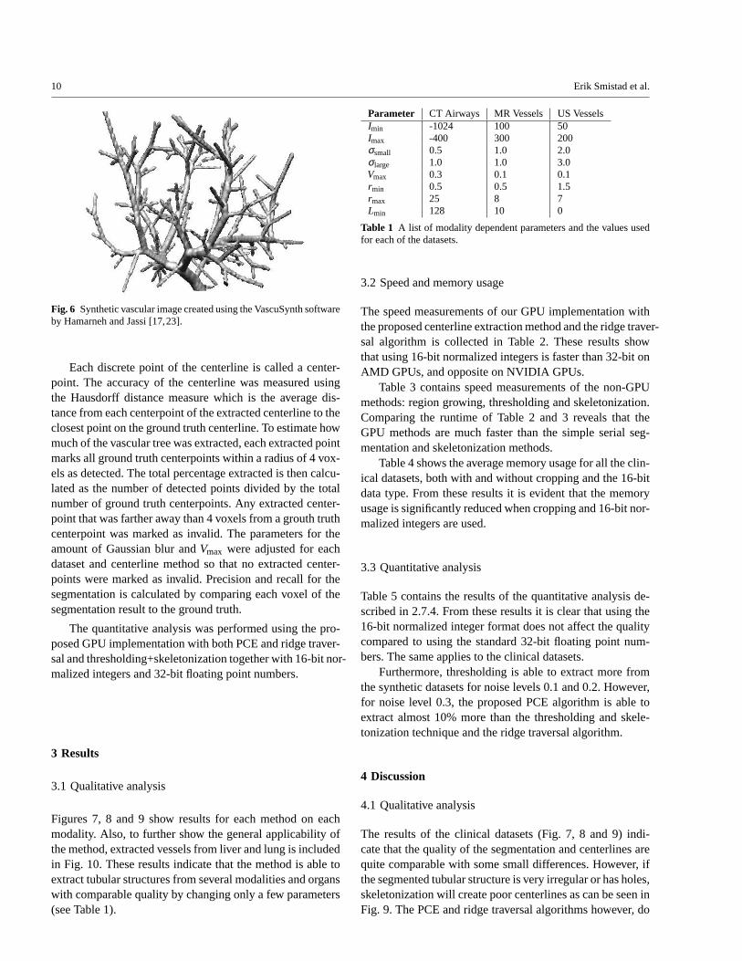
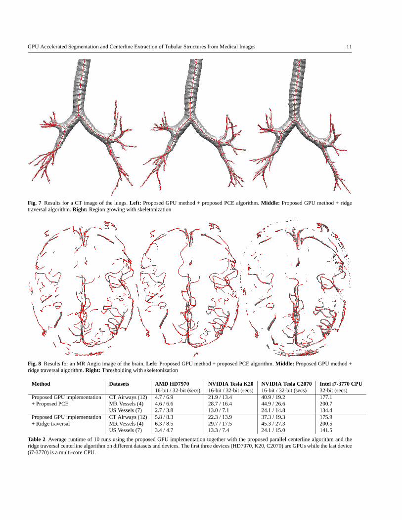
Figures 7, 8 and 9 show results for each method on eachmodality. Also, to further show the general applicability ofthe method, extracted vessels from liver and lung is includedin Fig. 10. These results indicate that the method is able toextract tubular structures from several modalities and organswith comparable quality by changing only a few parameters(see Table 1).
Parameter CT Airways MR Vessels US VesselsImin -1024 100 50Imax -400 300 200σsmall 0.5 1.0 2.0σlarge 1.0 1.0 3.0Vmax 0.3 0.1 0.1rmin 0.5 0.5 1.5rmax 25 8 7Lmin 128 10 0
Table 1 A list of modality dependent parameters and the values usedfor each of the datasets.
3.2 Speed and memory usage
The speed measurements of our GPU implementation withthe proposed centerline extraction method and the ridge traver-sal algorithm is collected in Table 2. These results showthat using 16-bit normalized integers is faster than 32-bitonAMD GPUs, and opposite on NVIDIA GPUs.
Table 3 contains speed measurements of the non-GPUmethods: region growing, thresholding and skeletonization.Comparing the runtime of Table 2 and 3 reveals that theGPU methods are much faster than the simple serial seg-mentation and skeletonization methods.
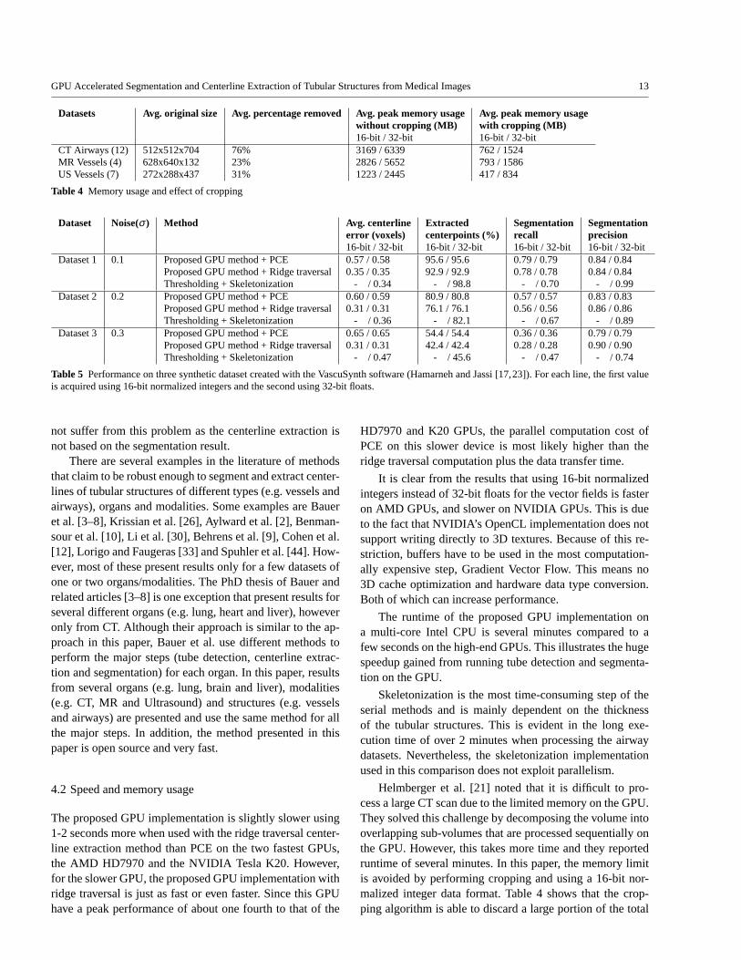
Table 4 shows the average memory usage for all the clin-ical datasets, both with and without cropping and the 16-bitdata type. From these results it is evident that the memoryusage is significantly reduced when cropping and 16-bit nor-malized integers are used.
3.3 Quantitative analysis
Table 5 contains the results of the quantitative analysis de-scribed in 2.7.4. From these results it is clear that using the16-bit normalized integer format does not affect the qualitycompared to using the standard 32-bit floating point num-bers. The same applies to the clinical datasets.
Furthermore, thresholding is able to extract more fromthe synthetic datasets for noise levels 0.1 and 0.2. However,for noise level 0.3, the proposed PCE algorithm is able toextract almost 10% more than the thresholding and skele-tonization technique and the ridge traversal algorithm.
4 Discussion
4.1 Qualitative analysis
The results of the clinical datasets (Fig. 7, 8 and 9) indi-cate that the quality of the segmentation and centerlines arequite comparable with some small differences. However, ifthe segmented tubular structure is very irregular or has holes,skeletonization will create poor centerlines as can be seeninFig. 9. The PCE and ridge traversal algorithms however, do
GPU Accelerated Segmentation and Centerline Extraction of Tubular Structures from Medical Images 11
Fig. 7 Results for a CT image of the lungs.Left: Proposed GPU method + proposed PCE algorithm.Middle: Proposed GPU method + ridgetraversal algorithm.Right: Region growing with skeletonization
Fig. 8 Results for an MR Angio image of the brain.Left: Proposed GPU method + proposed PCE algorithm.Middle: Proposed GPU method +ridge traversal algorithm.Right: Thresholding with skeletonization
Method Datasets AMD HD7970 NVIDIA Tesla K20 NVIDIA Tesla C2070 Intel i7-3770 CPU16-bit / 32-bit (secs) 16-bit / 32-bit (secs) 16-bit / 32-bit (secs) 32-bit (secs)
Proposed GPU implementation CT Airways (12) 4.7 / 6.9 21.9 / 13.4 40.9 / 19.2 177.1+ Proposed PCE MR Vessels (4) 4.6 / 6.6 28.7 / 16.4 44.9 / 26.6 200.7
US Vessels (7) 2.7 / 3.8 13.0 / 7.1 24.1 / 14.8 134.4Proposed GPU implementation CT Airways (12) 5.8 / 8.3 22.3 / 13.9 37.3 / 19.3 175.9+ Ridge traversal MR Vessels (4) 6.3 / 8.5 29.7 / 17.5 45.3 / 27.3 200.5
US Vessels (7) 3.4 / 4.7 13.3 / 7.4 24.1 / 15.0 141.5
Table 2 Average runtime of 10 runs using the proposed GPU implementation together with the proposed parallel centerline algorithm andtheridge traversal centerline algorithm on different datasets and devices. The first three devices (HD7970, K20, C2070) are GPUs while the last device(i7-3770) is a multi-core CPU.

12 Erik Smistad et al.
Fig. 9 Results for a 3D Ultrasound Doppler image of vessels in the brain.Left: Proposed GPU method + proposed PCE algorithm.Middle:Proposed GPU method + ridge traversal algorithm.Right: Thresholding with skeletonization
Fig. 10 Segmentation result from other organs using proposed GPU method.From left to right: Vessels of liver from CT, vessels of liver fromMRand vessels of one lung from CT.
Segmentation and centerline method Datasets Avg. runtime (seconds)Region Growing + Skeletonization CT Airways (12) 158Thresholding + Skeletonization MR Vessels (4) 77Thresholding + Skeletonization US Vessels (7) 33
Table 3 Average runtime of 10 runs using region growing, thresholding and skeletonization/thinning on different modalities.
GPU Accelerated Segmentation and Centerline Extraction of Tubular Structures from Medical Images 13
Datasets Avg. original size Avg. percentage removed Avg. peak memory usage Avg. peak memory usagewithout cropping (MB) with cropping (MB)16-bit / 32-bit 16-bit / 32-bit
CT Airways (12) 512x512x704 76% 3169 / 6339 762 / 1524MR Vessels (4) 628x640x132 23% 2826 / 5652 793 / 1586US Vessels (7) 272x288x437 31% 1223 / 2445 417 / 834
Table 4 Memory usage and effect of cropping
Dataset Noise(σ ) Method Avg. centerline Extracted Segmentation Segmentationerror (voxels) centerpoints (%) recall precision16-bit / 32-bit 16-bit / 32-bit 16-bit / 32-bit 16-bit / 32-bit
Dataset 1 0.1 Proposed GPU method + PCE 0.57 / 0.58 95.6 / 95.6 0.79 / 0.79 0.84 / 0.84Proposed GPU method + Ridge traversal0.35 / 0.35 92.9 / 92.9 0.78 / 0.78 0.84 / 0.84Thresholding + Skeletonization - / 0.34 - / 98.8 - / 0.70 - / 0.99
Dataset 2 0.2 Proposed GPU method + PCE 0.60 / 0.59 80.9 / 80.8 0.57 / 0.57 0.83 / 0.83Proposed GPU method + Ridge traversal0.31 / 0.31 76.1 / 76.1 0.56 / 0.56 0.86 / 0.86Thresholding + Skeletonization - / 0.36 - / 82.1 - / 0.67 - / 0.89
Dataset 3 0.3 Proposed GPU method + PCE 0.65 / 0.65 54.4 / 54.4 0.36 / 0.36 0.79 / 0.79Proposed GPU method + Ridge traversal0.31 / 0.31 42.4 / 42.4 0.28 / 0.28 0.90 / 0.90Thresholding + Skeletonization - / 0.47 - / 45.6 - / 0.47 - / 0.74
Table 5 Performance on three synthetic dataset created with the VascuSynth software (Hamarneh and Jassi [17,23]). For each line, the first valueis acquired using 16-bit normalized integers and the second using 32-bit floats.
not suffer from this problem as the centerline extraction isnot based on the segmentation result.
There are several examples in the literature of methodsthat claim to be robust enough to segment and extract center-lines of tubular structures of different types (e.g. vessels andairways), organs and modalities. Some examples are Baueret al. [3–8], Krissian et al. [26], Aylward et al. [2], Benman-sour et al. [10], Li et al. [30], Behrens et al. [9], Cohen et al.[12], Lorigo and Faugeras [33] and Spuhler et al. [44]. How-ever, most of these present results only for a few datasets ofone or two organs/modalities. The PhD thesis of Bauer andrelated articles [3–8] is one exception that present results forseveral different organs (e.g. lung, heart and liver), howeveronly from CT. Although their approach is similar to the ap-proach in this paper, Bauer et al. use different methods toperform the major steps (tube detection, centerline extrac-tion and segmentation) for each organ. In this paper, resultsfrom several organs (e.g. lung, brain and liver), modalities(e.g. CT, MR and Ultrasound) and structures (e.g. vesselsand airways) are presented and use the same method for allthe major steps. In addition, the method presented in thispaper is open source and very fast.
4.2 Speed and memory usage
The proposed GPU implementation is slightly slower using1-2 seconds more when used with the ridge traversal center-line extraction method than PCE on the two fastest GPUs,the AMD HD7970 and the NVIDIA Tesla K20. However,for the slower GPU, the proposed GPU implementation withridge traversal is just as fast or even faster. Since this GPUhave a peak performance of about one fourth to that of the
HD7970 and K20 GPUs, the parallel computation cost ofPCE on this slower device is most likely higher than theridge traversal computation plus the data transfer time.
It is clear from the results that using 16-bit normalizedintegers instead of 32-bit floats for the vector fields is fasteron AMD GPUs, and slower on NVIDIA GPUs. This is dueto the fact that NVIDIA’s OpenCL implementation does notsupport writing directly to 3D textures. Because of this re-striction, buffers have to be used in the most computation-ally expensive step, Gradient Vector Flow. This means no3D cache optimization and hardware data type conversion.Both of which can increase performance.
The runtime of the proposed GPU implementation ona multi-core Intel CPU is several minutes compared to afew seconds on the high-end GPUs. This illustrates the hugespeedup gained from running tube detection and segmenta-tion on the GPU.
Skeletonization is the most time-consuming step of theserial methods and is mainly dependent on the thicknessof the tubular structures. This is evident in the long exe-cution time of over 2 minutes when processing the airwaydatasets. Nevertheless, the skeletonization implementationused in this comparison does not exploit parallelism.
Helmberger et al. [21] noted that it is difficult to pro-cess a large CT scan due to the limited memory on the GPU.They solved this challenge by decomposing the volume intooverlapping sub-volumes that are processed sequentially onthe GPU. However, this takes more time and they reportedruntime of several minutes. In this paper, the memory limitis avoided by performing cropping and using a 16-bit nor-malized integer data format. Table 4 shows that the crop-ping algorithm is able to discard a large portion of the total

14 Erik Smistad et al.
input volume. This reduces memory usage significantly andwithout it, no GPU at the present time would have enoughmemory to perform the entire calculation in one step forlarge medical images. Using 16-bit for storage also halvesthe memory usage allowing larger volumes to be processedentirely on the GPU. On average, the peak memory usage isbelow 1 GB when cropping and 16-bit data types are used,which is below the memory limit of most modern GPUs.
4.3 Quantitative analysis
The average centerline error is worse for the proposed PCEalgorithm than the ridge traversal and skeletonization meth-ods. This increased centerline error is due to the fact that thePCE algorithm creates straight lines between centerpoints.However, it is below 0.7 voxels which we argue is not prob-lematic for most applications and this approximation en-ables the proposed PCE algorithm to extract over 10% moreof the synthetic vascular tree compared to the ridge traversalalgorithm for large noise levels (0.3).
Thresholding assumes that all voxels with an intensityabove some threshold is part of the tubular structures. Thisassumption is correct for these synthetic datasets and is thusable to extract more for noise levels 0.1 and 0.2. However,this assumption is usually never correct for a clinical datasetand especially not if the noise level is high. This is evidentwith noise level 0.3 and in the MR Angio modality in Fig.8 where the segmentation contains some noise and parts ofthe cranium.
5 Conclusion
In this article, a fast and generic method that can extracttubular structures such as blood vessels and airways fromimages of different modalities (CT, MR and US) and organs(brain, lungs and liver) was presented. This was achieved byutilizing the computational power of modern Graphic Pro-cessing Units. The method was compared to other meth-ods such as region growing, thresholding, skeletonizationbythinning and ridge traversal. Results from both synthetic andclinical datasets from three different modalities (CT, MRand US) was presented. The results show that the method isable to extract airways and vessels in 3-5 seconds on a mod-ern GPU. These near real-time speeds can be beneficial inreducing processing time in image guided surgery applica-tions such as bronchoscopy, laparoscopy and neurosurgery.Although faster and more general than other methods, thequality of the centerline and segmentation was found to becomparable for all the methods.
Acknowledgements Thank you to the people of the Heterogeneousand Parallel Computing Lab at NTNU for all their assistance and St.
Olav’s University Hospital for the datasets. The authors would alsolike to convey thanks to NTNU and NVIDIA’s CUDA Research CenterProgram for their hardware contributions to the HPC Lab. Without theircontinued support this project would not have been possible.
Conflict of interest Erik Smistad, Anne C. Elster and Frank Lindsethdeclare that they have no conflict of interest.
References
1. AMD. AMD Accelerated Parallel Processing OpenCLProgramming Guide. Technical Report December, 2012.http://developer.amd.com/download/AMDAcceleratedParallelProcessingOpenCLProgrammingGuide.pdf - accessed 4. July2013.
2. S. R. Aylward and E. Bullitt. Initialization, noise, singularities,and scale in height ridge traversal for tubular object centerlineextraction. IEEE transactions on medical imaging, 21(2):61–75,Feb. 2002.
3. C. Bauer.Segmentation of 3D Tubular Tree Structures in MedicalImages. PhD thesis, Graz University of Technology, 2010.
4. C. Bauer and H. Bischof. A novel approach for detection of tubularobjects and its application to medical image analysis. InProceed-ings of the 30th DAGM Symposium on Pattern Recognition, pages163–172. Springer, 2008.
5. C. Bauer and H. Bischof. Edge based tube detection for coronaryartery centerline extraction.The Insight Journal, 2008.
6. C. Bauer and H. Bischof. Extracting curve skeletons from grayvalue images for virtual endoscopy. InProceedings of the 4thInternational Workshop on Medical Imaging and Augmented Re-ality, pages 393–402. Springer, 2008.
7. C. Bauer, H. Bischof, and R. Beichel. Segmentation of airwaysbased on gradient vector flow. InProceedings of the 2nd Interna-tional Workshop on Pulmonary Image Analysis. MICCAI, pages191–201. Citeseer, 2009.
8. C. Bauer, T. Pock, H. Bischof, and R. Beichel. Airway tree re-construction based on tube detection. InProceedings of the 2ndInternational Workshop on Pulmonary Image Analysis. MICCAI,pages 203–214. Citeseer, 2009.
9. T. Behrens, K. Rohr, and H. S. Stiehl. Robust segmentation oftubular structures in 3-D medical images by parametric object de-tection and tracking.IEEE transactions on systems, man, and cy-bernetics. Part B, Cybernetics : a publication of the IEEE Systems,Man, and Cybernetics Society, 33(4):554–61, Jan. 2003.
10. F. Benmansour and L. D. Cohen. Tubular Structure SegmentationBased on Minimal Path Method and Anisotropic Enhancement.International Journal of Computer Vision, 92(2):192–210, Mar.2010.
11. M. Billeter, O. Olsson, and U. Assarsson. Efficient stream com-paction on wide SIMD many-core architectures. InProceedingsof the Conference on High Performance Graphics, pages 159–166,2009.
12. L. D. Cohen and T. Deschamps. Segmentation of 3D tubular ob-jects with adaptive front propagation and minimal tree extractionfor 3D medical imaging.Computer methods in biomechanics andbiomedical engineering, 10(4):289–305, Aug. 2007.
13. O. Eidheim, J. Skjermo, and L. Aurdal. Real-time analysis ofultrasound images using GPU.International Congress Series,1281:284–289, May 2005.
14. M. Erdt, M. Raspe, and M. Suehling. Automatic hepatic vesselsegmentation using graphics hardware. InProceedings of the 4thinternational workshop on Medical Imaging and Augmented Re-ality, pages 403–412, 2008.
15. A. Frangi, W. Niessen, K. Vincken, and M. Viergever. Multi-scale vessel enhancement filtering.Medical Image Computing andComputer-Assisted Interventation, 1496:130–137, 1998.
GPU Accelerated Segmentation and Centerline Extraction of Tubular Structures from Medical Images 15
16. M. W. Graham, J. D. Gibbs, D. C. Cornish, and W. E. Higgins.Robust 3-D airway tree segmentation for image-guided peripheralbronchoscopy.IEEE transactions on medical imaging, 29(4):982–97, Apr. 2010.
17. G. Hamarneh and P. Jassi. VascuSynth: simulating vascular treesfor generating volumetric image data with ground-truth segmenta-tion and tree analysis.Computerized medical imaging and graph-ics, 34(8):605–616, Dec. 2010.
18. M. Hassouna and A. Farag. On the extraction of curve skeletonsusing gradient vector flow. InIEEE 11th International Conferenceon Computer Vision, pages 1–8. IEEE, 2007.
19. K. Hawick, a. Leist, and D. Playne. Parallel graph component la-belling with GPUs and CUDA.Parallel Computing, 36(12):655–678, Dec. 2010.
20. Z. He and F. Kuester. GPU-Based Active Contour SegmentationUsing Gradient Vector Flow. InAdvances in Visual Computing,pages 191–201, 2006.
21. M. Helmberger, M. Urschler, M. Pienn, Z. Balint, A. Olschewski,and H. Bischof. Pulmonary Vascular Tree Segmentation fromContrast-Enhanced CT Images. InProceedings of the 37th An-nual Workshop of the Austrian Association for Pattern Recogni-tion, pages 1–10, Apr. 2013.
22. H. Homann. Implementation of a 3D thinning algorithm.TheInsight Journal, 2007.
23. P. Jassi and G. Hamarneh. VascuSynth: Vascular Tree SynthesisSoftware.The Insight Journal, 2011.
24. M. Kass, A. Witkin, and D. Terzopoulos. Snakes: Active contourmodels.International Journal of Computer Vision, 1(4):321–331,Jan. 1988.
25. C. Kirbas and F. Quek. A review of vessel extraction techniquesand algorithms. ACM Computing Surveys, 36(2):81–121, June2004.
26. K. Krissian, G. Malandain, and N. Ayache. Model-Based Detec-tion of Tubular Structures in 3D Images.Computer Vision andImage Understanding, 80(2):130–171, Nov. 2000.
27. T.-Y. Law and P. A. Heng. Automated extraction of bronchusfrom3D CT images of lung based on genetic algorithm and 3D regiongrowing. Proceedings of SPIE, 3979:906–916, 2000.
28. T. Lee, R. Kashyap, and C. Chu. Building skeleton models via3-D medial surface/axis thinning algorithms.CVGIP: GraphicalModel and Image Processing, 56(6):462–478, 1994.
29. D. Lesage, E. D. Angelini, I. Bloch, and G. Funka-Lea. A reviewof 3D vessel lumen segmentation techniques: models, features andextraction schemes.Medical image analysis, 13(6):819–845, Dec.2009.
30. H. Li and A. Yezzi. Vessels as 4-D curves: global minimal 4-Dpaths to extract 3-D tubular surfaces and centerlines.IEEE trans-actions on medical imaging, 26(9):1213–23, Sept. 2007.
31. P. Lo, B. V. Ginneken, J. M. Reinhardt, and M. de Bruijne. Extrac-tion of Airways from CT (EXACT’09). InSecond InternationalWorkshop on Pulmonary Image Analysis, pages 175–189, 2009.
32. P. Lo, J. Sporring, H. Ashraf, J. J. H. Pedersen, and M. de Bruijne.Vessel-guided airway tree segmentation: A voxel classification ap-proach.Medical image analysis, 14(4):527–538, Mar. 2010.
33. L. Lorigo and O. Faugeras. Codimension-two geodesic active con-tours for the segmentation of tubular structures. InComputer Vi-sion and Pattern Recognition, pages 444–451, 2000.
34. J. B. A. Maintz and M. A. Viergever. A survey of medical imageregistration.Medical Image Analysis, 2(1):1–36, 1998.
35. R. Malladi, J. Sethian, and B. Vemuri. Shape Modeling with FrontPropagation: A Level Set Approach.IEEE Transactions on Pat-tern Analysis and Machine Intelligence, 17(2):158–175, 1995.
36. A. Narayanaswamy, S. Dwarakapuram, C. S. Bjornsson, B. M.Cutler, W. Shain, and B. Roysam. Robust adaptive 3-D segmen-tation of vessel laminae from fluorescence confocal microscopeimages and parallel GPU implementation.IEEE transactions onmedical imaging, 29(3):583–597, Mar. 2010.
37. NVIDIA. OpenCL Best Practices Guide. Technical report,2010. http://www.nvidia.com/content/cudazone/CUDABrowser/downloads/papers/NVIDIAOpenCLBestPracticesGuide.pdf -accessed 4. July 2013.
38. I. Reinertsen, F. Lindseth, G. Unsgaard, and D. L. Collins. Clinicalvalidation of vessel-based registration for correction of brain-shift.Medical image analysis, 11(6):673–684, Dec. 2007.
39. L. Shi, W. Liu, H. Zhang, Y. Xie, and D. Wang. A survey of GPU-based medical image computing techniques.Quantitative Imagingin Medicine and Surgery, 2(3):188–206, 2012.
40. I. Sluimer, A. Schilham, M. Prokop, and B. van Ginneken. Com-puter Analysis of Computed Tomography Scans of the Lung: ASurvey. IEEE transactions on medical imaging, 25(4):385–405,Apr. 2006.
41. E. Smistad, A. C. Elster, and F. Lindseth. GPU-Based Air-way Segmentation and Centerline Extraction for Image GuidedBronchoscopy. InNorsk informatikkonferanse, pages 129–140.Akademika forlag, 2012.
42. E. Smistad, A. C. Elster, and F. Lindseth. Real-time gradient vec-tor flow on GPUs using OpenCL.Journal of Real-Time ImageProcessing, 2012.
43. E. Smistad, A. C. Elster, and F. Lindseth. Real-Time SurfaceExtraction and Visualization of Medical Images using OpenCLand GPUs. InNorsk informatikkonferanse, pages 141–152.Akademika forlag, 2012.
44. C. Spuhler, M. Harders, and G. Szekely. Fast and Robust Extrac-tion of Centerlines in 3D Tubular Structures Using a Scattered-Snakelet Approach.Proc. SPIE, 6144, Mar. 2006.
45. B. van Ginneken, W. Baggerman, and E. M. van Rikxoort. Ro-bust segmentation and anatomical labeling of the airway tree fromthoracic CT scans.International Conference on Medical ImageComputing and Computer-Assisted Intervention, 11:219–26, Jan.2008.
46. A. Vasilevskiy and K. Siddiqi. Flux maximizing geometric flows.IEEE Transactions on Pattern Analysis and Machine Intelligence,24(12):1565–1578, Dec. 2002.
47. C. Xu and J. Prince. Snakes, shapes, and gradient vector flow.Image Processing, IEEE Transactions on, 7(3):359–369, 1998.
48. Z. Zheng and R. Zhang. A Fast GVF Snake Algorithm on theGPU. Research Journal of Applied Sciences, Engineering andTechnology, 4(24):5565–5571, 2012.
49. G. Ziegler, A. Tevs, C. Theobalt, and H. Seidel. On-the-flypointclouds through histogram pyramids. InVision, modeling, and vi-sualization 2006: proceedings, November 22-24, 2006, Aachen,Germany, page 137. IOS Press, 2006.