g.p. hancke, eavesdropping attacks on high-frequency rfid ... · eavesdropping attacks on...
TRANSCRIPT
Eavesdropping Attacks on High-Frequency RFID Tokens
G.P. Hancke
Smart Card Centre, Information Security GroupRoyal Holloway, University of London
Egham TW20 0EX, [email protected]
Abstract. RFID systems often use near-field magnetic coupling to implement communicationchannels. The advertised operational range of these channels is less than 10 cm and thereforeseveral implemented systems assume that the communication channel is location limited andtherefore relatively secure. Nevertheless, there have been repeated questions raised about thevulnerability of these near-field systems against eavesdropping and skimming attacks. In thispaper I revisit the topic of RFID eavesdropping attacks, surveying previous work and explainingwhy the feasibility of practical attacks is still a relevant and novel research topic. I present a briefoverview of the radio characteristics for popular HF RFID standards and present some practicalresults for eavesdropping experiments against tokens adhering to the ISO 14443 and ISO 15693standards. Finally, I discuss how an attacker could construct a low-cost eavesdropping deviceusing easy to obtain parts and reference designs.
Keywords: Eavesdropping, RFID, contactless, near-field communication
1 Introduction
High-frequency RFID tokens, using near-field channels, are used to store valuable informationin cashless payment systems and even travel documents. No physical contact needs to bemade with the reader, which simplifies operation and increases overall transaction speeds.A growing security concern with RFID devices is the possible release of the user’s personalinformation, or location, to unauthorized parties. For example, some consumer groups haverallied against the ‘big brother’ potential of RFID technology [31]. As RFID tokens are alsoused for transactions of increasing value, they could become the target of lone opportunisticattackers, who, if able to gain access to the information on the RFID token, might be able toengage in the act of ‘digital pick-pocketing’ while just standing next to the victim. The twomain attacks usually considered are skimming and eavesdropping.
Eavesdropping attacks are a well known risk for RFID devices and there are severalclaims about the possibility of these attacks on RFID tokens, for example [32]. The distancesat which these attacks are possible are often debated and used as an indication of RFID se-curity, for example [27], so this is an important factor when considering the threat model forRFID devices. Despite this interest, few publications provide details about possible experi-mental setup or practical results. In this paper I discuss the implementation of eavesdroppingattacks on HF RFID and present some practical results for eavesdropping on systems usingthe ISO 14443A/B and ISO 15693 standards. In each case I provide a detailed explanationof the experimental method and description of the setup. My main contribution is to provide
1 Proceedings of the 4th Workshop on RFID Security (RFIDsec’08), pp 100–113, July 2008.

a reference experimental setup for RFID eavesdropping to provide a better understanding ofthe attack’s physical constraints as opposed to theoretical simulation. This would hopefullyallow system designers to comprehend the eavesdropping threat in order to select appropri-ate technologies and countermeasures. Finally, I also discuss how an attacker with limitedresources could construct and eavesdropping receiver.
2 Eavesdropping scenarios
Eavesdropping normally occurs when the attacker intercepts communication between anRFID token and an authorized reader. The attacker does not need to power or commu-nicate with the token, so he is able to execute the attack from a greater distance than ispossible for skimming. He is, however, limited in terms of location and time window, sincehe has to be in the vicinity of an authorized reader when a transaction that he is interestedin, is conducted. The attacker needs to capture the transmitted signals using suitable RFequipment before recovering and storing the data of interest. The degree of success that theattacker will achieve depends on the resources available to him. An attacker with expensive,specialized RF measurement equipment will almost certainly be able to eavesdrop from fur-ther away than an attacker with a cheap, home-made system. The attack is still a viablethreat either way. An opportunistic attacker could possibly recover the travel card details ofthe person standing in front of him at an entrance gate if he had a small, portable systemthat could eavesdrop at 50 cm. Alternatively, if the attacker is able to successfully eavesdropthe communication from 10 m he could sit in a vehicle outside his local corner store andrecord the payment transactions conducted inside.
In the HF RFID standards the communication schemes used for reader-to-token (forwardchannel) and token-to-reader (backward channel) are different. As a result the distances atwhich an attacker can recover the data sent on the forward and backward channels differ.There are three distances to consider for this attack:
– The distance at which an attacker can detect a transaction, i.e. he can see the forwardchannel but cannot reliably recover the actual data.
– The distance at which an attacker can reliably recover the data sent on the forwardchannel.
– The distance at which an attacker can reliably recover the data sent on the backwardchannel.
Near-field communication generally uses different modulation schemes for the forward andthe backward channel. In practice, this means that the eavesdropping ranges for each of thesechannels are different. I therefore define DEF as the distance at which the forward channelcan be observed and DEB as the distance at which the backward channel can be observed.The data transmitted depends on the specific application, but the attacker is typically moreinterested in the backward channel because this contains data contained in the token, ratherthan generic instructions sent by the reader. The exceptions are when an attacker simplywishes to determine whether a transaction took place, in which case he only needs to recoverthe channel with the greatest eavesdropping distance, or when information on the weakerbackward channel is echoed on the stronger forward channel. For the purpose of my work Iassume an eavesdropping attack to be successful at a certain distance when both the forwardand backward channels can be observed at this distance.

2.1 Related work
Eavesdropping attacks are not new and are mentioned regularly in the literature. Recentreports by the National Institute of Standards and Technology (NIST) [22], the Departmentof Homeland Security (DHS) [6] and the German Federal Office for Information Security(BSI) [3], along with academic surveys, e.g. [16], all mention scenarios for eavesdroppingattacks in the RFID environment. These reports, however, do not show practical results orfail to clarify the experimental setup if they do.
Different scenarios exist for eavesdropping attacks and therefore the experimental setupshould be known in order for published results to be useful. In earlier reports terms used todescribe the attacks were also confusing. A report on ‘Port of Entry’ tests done in 2004 [7]states that signals from e-passport systems could be ‘detected’ at 20 m. The report does notexplain whether this implies that the attacker could detect that a transaction occurred, orwhether he could recover the actual data. The test also covered a number of different systemsand no details were given about which system yielded the result. There were also pressreports that NIST eavesdropped the RFIDs to be used in USA passports from as far awayas 9 m [37]. Reports, however, often used the term ‘read’, which implied a skimming attack,while they were actually describing eavesdropping. There are also cases where reports do notstate clearly which type of token they were referring to when describing attack distances.RFID is a collective term for several systems and in reality refers to devices adhering to anumber of different standards. An HF token used for a contactless smart card is not the sameas a UHF token used in logistics. Therefore, if somebody can read a razor’s tag from 1 mit cannot be assumed that the same is true for an e-passport. It is therefore important toclearly state the type of RFID system when describing these attacks. Yet the American CivilLiberties Union (ACLU) demo, where a ‘passport’ was read from 1 m, used ‘similar’ RFIDtechnology and not an ISO 14443 token as used in a real e-passport [27].
The first academic short paper discussing practical attacks on HF RFID devices wasofficially published in early 2006 [10]. Another work-in-progress report was released by re-searchers at the BSI, where they demonstrated eavesdropping at a distance of 2 m [8] onan ISO 14443A card. Riscure, a Dutch security company, later claimed that it was possibleto eavesdrop the backward communication at a distance of 5 m, and the forward channel ata distance of 25 m [32]. They have, however, not actually implemented the attack. At theend of 2006 NIST published a report [9], which was reported in [22], to show that ISO 14443tokens could be eavesdropped at 15 m. I have only recently obtained a copy of this document,the content of which is discussed together with my own results in Section 5. Other industrialstudies are often referenced in literature, e.g. NXP white paper [36] cited in document byEurosmart [30], but then unavailable as public documentation. My work tries to build on theearly work-in-progress papers [8, 10] by formalising the experimental process and expandingthe experimental results to include ISO 14443B and ISO 15693 tokens.
2.2 Significance
The recovery of useful data by eavesdropping can be prevented by encrypting the transmit-ted data with a suitable algorithm. Some HF RFID tokens are basically contactless smartcards, which can easily cope with implementing application layer security. So why are these
attacks still important? In earlier systems near-field communication was seen as secure be-cause the specified operational range was seen to be limited and as a result several weaksecurity measures were implemented. This section briefly discusses some security sensitiveRFID applications and their perceived weaknesses soon after deployment.
Credit cards: New contactless payment systems, of which the majority adhere to ISO14443A, are in widespread use today. RFID credit cards have, however, been used in theUSA since 2003, where these are also implemented using the ISO 14443B communicationstandard. Not enough information is currently available to comment on the new contactlesspayment systems, but a study has shown there to be a number of vulnerabilities in the firstgeneration of USA credit cards [11]. User and banking information were often sent in plaintextbetween the reader and the RFID-enabled cards. An attacker could also retrieve the data byimplementing a skimming attack and the information transmitted on the RF channel wasallegedly sufficient to imitate a valid card.
e-Passports: By 26 October 2006 the USA required that 27 countries issue their citizenswith e-passports in order to still qualify under the Visa Waiver Program. E-passports ad-here to operational specifications as defined by the International Civil Aviation Organisation(ICAO) [12] and use the ISO 14443 standard. ICAO allows for optional security protocols,such as Basic Access Control (BAC), that provides both authentication and encryption ser-vices. BAC derives a key from the passport serial number, expiry date and the user’s birthday,read off the OCR strip inside the passport. The idea is that anyone presented with the pass-port can read the OCR data, derive the key and retrieve the data off the RFID token inside.Security problems of this scheme have been pointed out [17], especially with the effective sizeof the key. Theoretically the data can be used to generate a key with an effective length of atleast 50 bits [19]. Predictability in the data could however decrease the effective key lengthto 35 [32] or even 27 [17] bits, which makes a brute force key search attack feasible. Thisimplies that an attacker could eavesdrop communication between a passport and reader andtry to decrypt it at a later stage exploiting this weakness in the key. An overview of the latestissues regarding e-passports is presented in [2].
Travel and Access Control Tokens: HF RFID tokens are also used in a number oftravel and access control systems. Recently, the proprietary Crypto1 cryptographic algorithmused in NXP’s Mifare Classic product range was reverse engineered and published [25]. Fur-ther analysis of this cipher revealed cryptographic vulnerabilities that could be exploited torecover key material in a matter of minutes [5]. An attacker wishing to execute such attacks,however, might first need to reliably eavesdrop transactions between the card and the reader.
3 Experimental setup
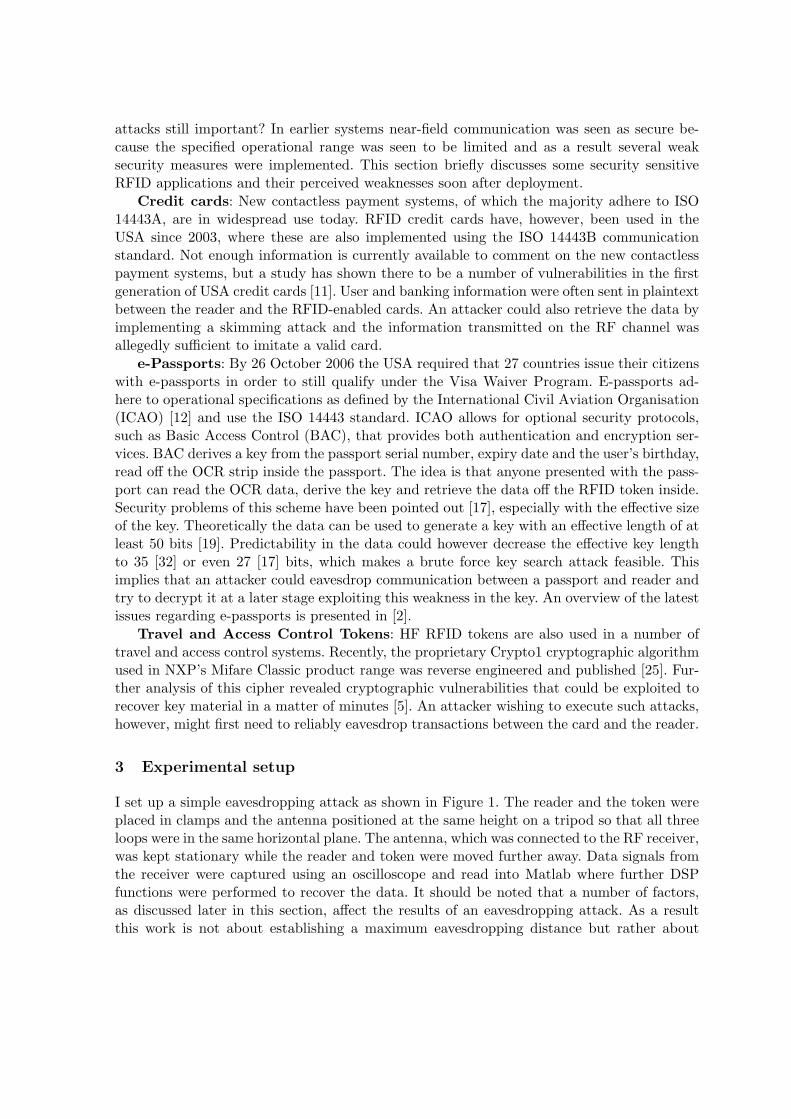
I set up a simple eavesdropping attack as shown in Figure 1. The reader and the token wereplaced in clamps and the antenna positioned at the same height on a tripod so that all threeloops were in the same horizontal plane. The antenna, which was connected to the RF receiver,was kept stationary while the reader and token were moved further away. Data signals fromthe receiver were captured using an oscilloscope and read into Matlab where further DSPfunctions were performed to recover the data. It should be noted that a number of factors,as discussed later in this section, affect the results of an eavesdropping attack. As a resultthis work is not about establishing a maximum eavesdropping distance but rather about

(a) Observing and capturing communication (b) Experimental setup
Fig. 1. Setup for the eavesdropping experiment
practically implementing a proof-of-concept attack using a documented method that can bere-created by other researchers to obtain comparable results for their specific environment.
3.1 Equipment
There are commerical RF receivers available that can be used to demonstrate the eavesdrop-ping attack. I used the R-1250 Wide Range Receiver and the R-1150-10A Portable AntennaKit, both manufactured by Dynamic Sciences. The R-1250 is a superheterodyne receiver op-erating from 100 Hz to 1 GHz with 21 selectable bandwidths, increasing in steps of 1-2-5from 50 Hz to 200 MHz, centered around 200 kHz or 30 MHz IF frequencies. The receiverallows the user to adjust the RF and pre-detection gain over 50 dB and 30 dB respectively.The user can then choose whether to use the AM, FM or IF output available. Detailed infor-mation about the R-1250 receiver, including calibration data for the specific receiver used inthe attack, can be found in [20, pp 23–33]. The antenna kit includes a set of H-field ferritecore antennas for field-strength measurements in the 100 Hz to 30 MHz range. Looking atthe H-field is of particular interest when taking into account the dominance of the H-field inthe near-field of loop antennas.
Currently there are three popular standards for passive near-field devices operating atthe frequency of 13.56 MHz: ISO 14443A, ISO 14443B [13] and ISO 15693 [14]. Since eachstandard has a different communication scheme it would not suffice to make claims abouteavesdropping HF devices without investigating all the standards.
For the eavesdropping experiment I used the ACG Multi-ISO RFID Reader (Antennadimension: 9 cm × 6 cm). I then used the following tokens: NXP Mifare Classic [24] forISO 14443A, contactless payment card for ISO 14443B and NXP I-Code [23] for ISO 15693.I would like to point out that I used these products because they were good examples ofdifferent HF systems implemented today using the three main HF RFID standards. I do notwish to imply that any of these products are more at risk of eavesdropping than anothercomparable product.
3.2 Environment
12.4 12.6 12.8 13.0 13.2 13.4 13.6 13.8 14.0 14.2 14.4 14.60
0.005
0.01
0.015
0.02
0.025
0.03
0.035
0.04
0.045
0.05
Frequency (MHz)
|Y(f
)|
(a) Main entrance hall
12.4 12.6 12.8 13.0 13.2 13.4 13.6 13.8 14.0 14.2 14.4 14.60
0.005
0.01
0.015
0.02
0.025
0.03
0.035
0.04
0.045
0.05
Frequency (MHz)
|Y(f
)|
(b) Hardware lab corridor
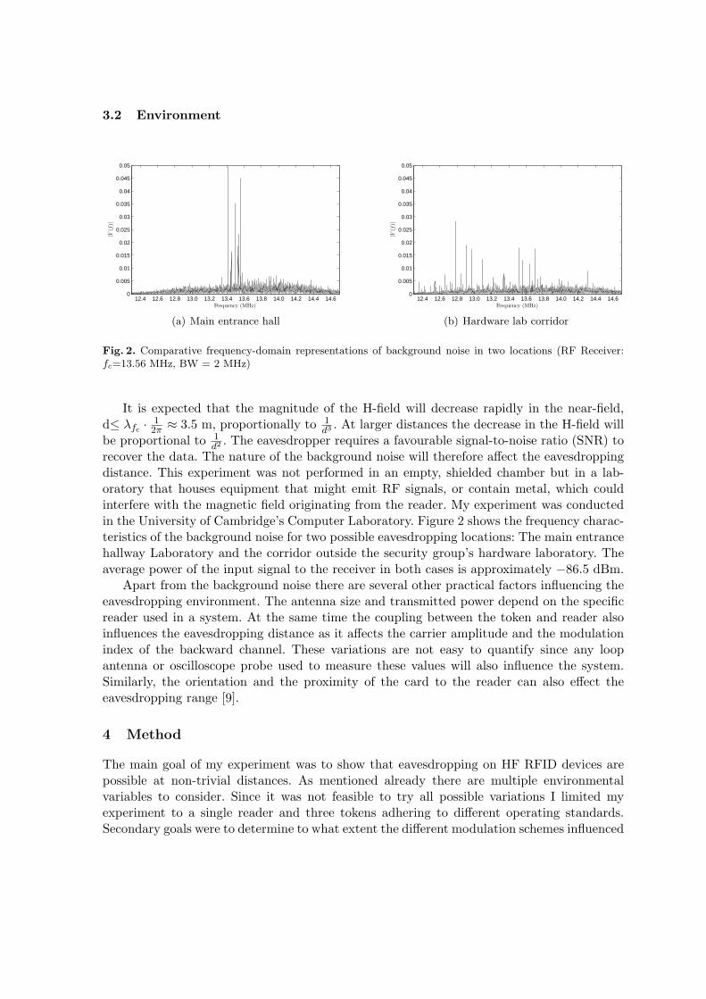
Fig. 2. Comparative frequency-domain representations of background noise in two locations (RF Receiver:fc=13.56 MHz, BW = 2 MHz)
It is expected that the magnitude of the H-field will decrease rapidly in the near-field,d≤ λfc
· 1
2π≈ 3.5 m, proportionally to 1
d3 . At larger distances the decrease in the H-field willbe proportional to 1
d2 . The eavesdropper requires a favourable signal-to-noise ratio (SNR) torecover the data. The nature of the background noise will therefore affect the eavesdroppingdistance. This experiment was not performed in an empty, shielded chamber but in a lab-oratory that houses equipment that might emit RF signals, or contain metal, which couldinterfere with the magnetic field originating from the reader. My experiment was conductedin the University of Cambridge’s Computer Laboratory. Figure 2 shows the frequency charac-teristics of the background noise for two possible eavesdropping locations: The main entrancehallway Laboratory and the corridor outside the security group’s hardware laboratory. Theaverage power of the input signal to the receiver in both cases is approximately −86.5 dBm.
Apart from the background noise there are several other practical factors influencing theeavesdropping environment. The antenna size and transmitted power depend on the specificreader used in a system. At the same time the coupling between the token and reader alsoinfluences the eavesdropping distance as it affects the carrier amplitude and the modulationindex of the backward channel. These variations are not easy to quantify since any loopantenna or oscilloscope probe used to measure these values will also influence the system.Similarly, the orientation and the proximity of the card to the reader can also effect theeavesdropping range [9].
4 Method
The main goal of my experiment was to show that eavesdropping on HF RFID devices arepossible at non-trivial distances. As mentioned already there are multiple environmentalvariables to consider. Since it was not feasible to try all possible variations I limited myexperiment to a single reader and three tokens adhering to different operating standards.Secondary goals were to determine to what extent the different modulation schemes influenced

the eavesdropping range and to investigate whether data could be reliably recovered from arecording with a low SNR. The experiment was repeated in two different locations as discussedin the previous section.
4.1 Reference data
The first step of the eavesdropping experiment was to generate a set of reference data forlater comparison to the recovered data, and to identify the frequency bands containing thedata I wanted to eavesdrop. To generate reference data I required a transaction where thedata transmitted on the forward and backward channel was repeatable. The standards inquestion all have a command instructing the token to return a unique identifier, which wasideal as the data always stayed the same. I recorded the signal at the antenna of the readerand demodulated it to obtain the reference data. I then computed the frequency spectrumfor the forward and backward channels using the Fast Fourier Transform (FFT) to confirmmy theoretical estimation of the frequency bands that are of interest.
ISO 14443A: The reader transmits 106 kbit/s Modified Miller encoded data using 3 µspulses. The forward channel data should therefore be in the first 330 kHz of the spectrum.The token transmits 106 kbit/s Manchester encoded data, which is ASK modulated onto a847 kHz subcarrier. The backward channel should be in a 424 kHz band centered around847 kHz. The forward channel is amplitude modulated onto the 13.56 MHz carrier with amodulation index of 100%, while the backward channel has a modulation index of 8–12%.
ISO 14443B: The reader transmits 106 kbit/s NRZ encoded data. The forward channeldata should therefore be in the first 106 kHz of the spectrum. The token transmits 106 kbit/sNRZ encoded data, which is BPSK modulated onto a 847 kHz subcarrier. The backwardchannel should be in a 212 kHz band centered around 847 kHz. The forward channel is am-plitude modulated onto the 13.56 MHz carrier with a modulation index of 10%, while thebackward channel has a modulation index of 8–12%.
ISO 15693: The reader uses a ‘1 of 4’ PPM code with a 9.44 µs pulse to transmit26.48 kbit/s data. The forward channel data should therefore be in the first 106 kHz of thespectrum. The token transmits 26.48 kbit/s NRZ encoded data, which is ASK modulatedonto a 423 kHz subcarrier. The backward channel should be in the 53 kHz band centeredaround 423 kHz. The forward channel is amplitude modulated onto the 13.56 MHz carrierwith a modulation index of 10%, while the backward channel has a modulation index of8–12%.
4.2 Capturing and calibration
The second step was to capture the signals with the RF receiver and record them on theoscilloscope. In the experiments described in [10] the oscilloscope was triggered on the serialcommunication between the host PC and the reader. I decided to change this method asit was not an accurate reflection of an attacker’s actions. There was also a possibility thatthe additional cables connected to the reader could aid signals of interest to radiate, thereby
providing an inaccurate result. Instead I captured the 30 MHz IF output of the RF receiver fora duration of 320 ms at a sampling frequency of 100 MS/s, while the reader was continuouslyquerying the token’s identifier. For each eavesdropping scenario I made two captures, the firstwith the receiver’s center frequency and bandwidth set to 13.56 MHz and 2 MHz respectivelyand the second with the center frequency set to the applicable sideband, 14.4 MHz and 13.98MHz, with bandwidths of 500 kHz and 200 kHz respectively.
The RF gain of the receiver is adjusted by turning a knob, which does not provide anaccurate indication of the actual gain introduced. The relative gain of the receiver was there-fore measured before each sequence capture. This was done by providing a reference signal,a center-frequency sine wave, as input to the receiver. Its power in dBm was then adjusteduntil the receiver’s output corresponded to a chosen value on the oscilloscope: 224 mV root-mean-square for the 30 MHz IF output signal, which is approximately 0 dBm. This gain valuecan then be used to determine the power of the corresponding input from the antenna to thereceiver.
4.3 Data recovery
The final step is to recover the data from the recorded signal. The SNR of the data decreaseswith distance and eventually the data can no longer be verified visually, or recovered with asimple threshold function such as a comparator with hysteresis. This does not mean that thedata is lost, but that recovery requires further processing to limit the effect of the noise. Acommon way to reduce the effect of noise is to average several recordings of the same signal.I do not consider this option, because the attacker does not have multiple recordings as thetransaction is run only once. A number of receivers optimized to recover signals corruptedby Additive White Gaussian Noise (AWGN) have been proposed, such as the correlationreceiver [29, pp 233–244]. The correlation receiver uses N correlators, which projects thereceived signal r(t) onto N base functions fk(t).
yk =
∫ T
0
r(t)fk(t)dt, k = 1, 2, . . . , N
It should be noted that if the base function is rectangular the correlator becomes anintegrator.
yk =1√T
∫ T
0
r(t)dt,
I used additional pre-filtering and a correlation receiver to recover data from the stored noisysignal. For each of the standards’ forward and backward channels N = 1 and the base functionis rectangular. The only important parameter is T , which was assigned the following values:
– ISO 14443A: Forward channel T = 3 µs, backward channel T = 1
212 kHz = 4.72 µs.
– ISO 14443B: Forward channel T = 1
106 kHz = 9.44 µs, backward channel T = 1
106 kHz =9.44 µs.
– ISO 15693: Forward channel T = 9.44 µs, backward channel T = 1
52.96 kHz = 18.88 µs.
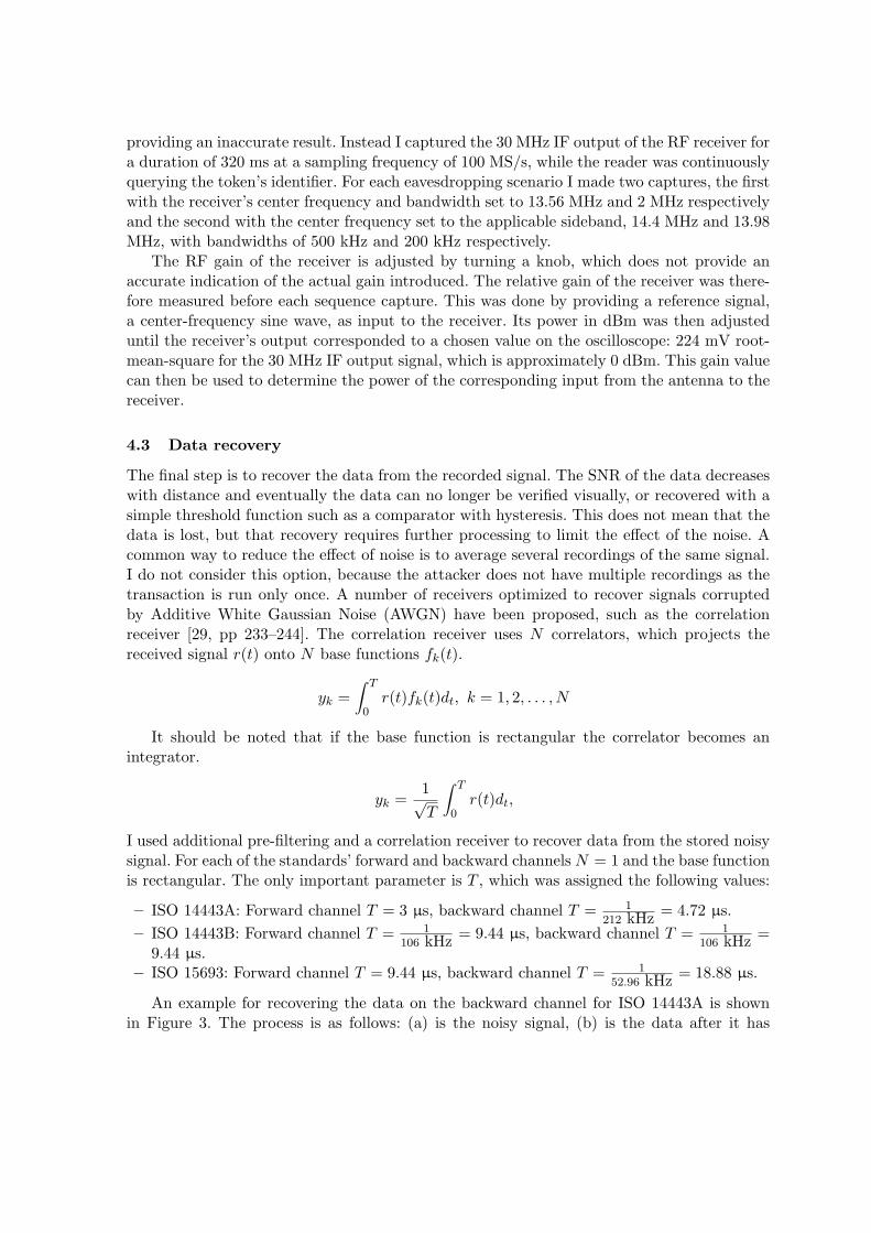
An example for recovering the data on the backward channel for ISO 14443A is shownin Figure 3. The process is as follows: (a) is the noisy signal, (b) is the data after it has

1 2 3 4 5 6 7 8 9 10 11 12 13 14 15 16 17 18 19 20
(f)
(e)
(d)
(c)
(b)
(a)
Fig. 3. Recovering the data from a noisy signal
been filtered using Finite Impulse Response (FIR) filters. The next step is to demodulatethe sub-carrier. For ASK I rectified the signal shown in (c) before correlating it with thebase function. (d) is the correlator output, which is then sampled to obtain the Manchesterencoded data (e). The Manchester data is decoded to NRZ and compared to the referencedata. The ISO standards define a strict bit-period grid, relative to the last bit sent by thereader, in which the token’s response must be sent. The sampling times can therefore bederived from the forward channel data. Alternatively, a clock recovery scheme as describedin [20, pp 125] can be implemented. The attacker can use known data, e.g. ISO 14443A ATQA
and SAK responses, to optimize his sampling thresholds, etc.
5 Results
Before presenting my results I first discuss the details of the eavesdropping test describedin [9]. This test uses a NXP Pegoda ISO 14443A reader and seven different ISO 14443Atokens from 4 manufacturers. The authors use a matched loop antenna and a ‘receiver system’(unspecified whether commercial equipment or custom build) in addition to an oscilloscopeand a protocol analyser to capture a token’s ID. A high level functional diagram of thereceiver is provided but no details are given about the filters, amplifiers and IF sectionsshown. An eavesdropping attempt is considered successful when the receiver’s output has aSNR greater than 6 dB, which is the level needed by the protocol analyser to obtain thecorrect ID. The experiment is performed with two different antenna setups: All three loopscentered around the same horizontal axis, which resulted in an eavesdropping distances of5–6.5 m, and all three loops in the same horizontal plane, the same as my setup, whichresulted in eavesdropping distances of 8–15 m. The fact that seven tokens, adhering to thesame standard and communicating with the same reader, yield different results is a goodexample of how eavesdropping distances vary depending on the specific system components.
My results are shown in Table 1. Even with additional signal processing I did not manageto achieve the distances in [9], although my results for ISO 14443 A tokens are similar to those

presented in [8]. There are, however, some interesting conclusions. The forward channel of theISO 14443 A and ISO 15693 communication can be eavesdropped at a much greater distancethan the backward channel, but for ISO 14443 B DEB is greater than DEF. In addition, it isonce again shown that results can vary for different locations since the ISO 14443B forwardchannel and ISO 14443 A backward channel could be recovered in one location, but not theother. In my environment I only achieved a SNA of 6 dB at a distance of approximately 1 m.
ISO 14443A ISO 14443B ISO 15693
Entrance hall1 m FB FB FB3 m Fx xB Fx5 m Fx xx Fx
10 m1 Fx xx Fx
Lab corridor3 m FB FB Fx4 m Fx xB Fx
Table 1. Eavesdropping results: F – Forward channel recovered, B – Backward channel recovered.
6 Eavesdropping attacks in the real world
An attacker can execute an eavesdropping attack if he acquired a suitable antenna, an RFreceiver and a method to sample and record the data. Even though I illustrated the eaves-dropping attack using commercial RF equipment I also want to point out that these attackscan work outside ‘laboratory conditions’ with cheap and portable hardware.
6.1 Receiver
The RF receiver converts the modulated HF carrier to a chosen IF after which the signalis filtered to isolate the frequency components that are of interest. The use of RF mixers iswell documented, e.g. [28], and detailed reference designs for receivers are publicly available,e.g. [26]. As a result, it is feasible to design and construct an RF receiver that could be usedto observe both the forward and backward communication of an ISO 14443 HF RFID systemfor less than £50. The receiver mixes the 14.40 MHz upper sideband down to an IF of 10.7MHz before using a 500 kHz band-pass filter to recover the sideband data and attenuate thestrong carrier. The filter also passes some higher harmonics of the forward channel data. Theforward channel pulse shapes are distorted although they are still in the correct position,which is enough information to recover the data in this case. My self-constructed receiverdid not achieve the same results as the commercial RF receiver but I managed to observecommunication at a range of 60 cm, with no additional amplifier between the antenna andmixer and a antenna of 10 cm radius. However, it shows that even a cash-strapped attackercan construct a suitable receiver that could be used in a real attack. In reality one should
1 Alternative antenna setup with all three loops on the same horizontal axis.

assume that an attacker may have more resources available, in other words he might be inthe position to purchase commercial RF equipment.
Antennas: A number of sources describe how to build HF antennas for receiving RFsignals, e.g. [4, 18]. Unfortunately these concentrate mainly on E-field antennas for radioapplications, although some practical construction and tuning tips still prove useful. Thesimplest option for building a magnetic antenna is to implement one of the reference designsfrom TI’s Antenna Cookbook [34], since most of the matching components and constructionmaterial are already specified. Alternatively, any form of loop antenna can be implementedand then matched using the guidelines in [35]. It should be noted that these guidelines specifycomponents with a higher power rating, since the antennas are also intended for transmitting.When the antennas are only used to receive signals, components with less stringent powerrequirements can be used. Enameled copper wire and adhesive copper tape can easily be usedto construct HF loop antennas of different sizes and number of loops. The resonant antennaalso acts as a crude bandpass filter around the chosen center frequency. The width of thepassband can be adjusted by changing the Q-factor.
Mixer: An optional amplifier stage can be added between the antenna and the mixer.The amplifier’s gain depends on the intended range of the receiver, i.e. short range proto-col analyzer or longer range eavesdropping, although it should be kept in mind that mostcommercial mixer ICs expect an input signal with smaller amplitude and some ICs also haveintegrated amplifiers. The mixer’s function is to move a spectral band of interest to a chosenintermediate frequency (IF) through direct downconversion. Normally, the advantage of IFsystems is that any input signal can be moved to a single IF frequency by using an adjustablemixing frequency, which simplifies the design of the filter bank. In my case the local oscilla-tor’s frequency can be fixed, but using an IF still simplifies the filter implementation sincethis allows the use of off-the-shelf filters designed for other applications. It is also possible toimplement zero-IF receivers that mixes the input down to the baseband (0 Hz). A lowpassfilter can then be used to remove the unwanted high frequency components.
Filter bank: Filtering helps to isolate the data of interest and remove unwanted frequencycomponents. The filter bank implementation depends on the IF chosen. Choosing an IF thatis often used in radio systems, like 10.7 MHz, simplifies the implementation since suitablefilters can be purchased. If the system needs to work at another IF it will require the designof custom filters. Information on filter design and relevant tools can be found from most ofthe large semiconductor manufacturers, e.g. [1, 21, 33]. It should be noted that both passiveand active high-frequency filters are sensitive to stray capacitance, or inductance, introducedby the circuit layout. The operational amplifiers selected for use in the active filters mustalso have adequate slew rate and gain bandwidth to function at the chosen IF.
6.2 Signal capture and demodulation:
The attacker needs to capture and demodulate the signal from his receiver. The samplingrate used by the attacker is dependent on the output of his receiver, since the rate needs to beat least twice the highest frequency component of the output to prevent aliasing effects. Forexample, if he used a zero IF receiver with a 1 MHz low pass filter he would need to sampleat 2 MHz. An attacker can choose to make a recording and perform data recovery later orimplement a real-time demodulator/decoder using a fast enough FPGA or DSP device. If the
attacker chose to store a recording the amount of memory needed will depend on the samplingrate chosen. For example, an attacker taking 8-bit samples at a rate of 2 MHz for 10 s wouldneed 20 MB of memory to store each recording. This would be higher if he uses oversamplingor if he needs to sample a higher IF output. These requirements are not unrealistic takeninto account that an attacker can acquire suitable hardware for a few £100, since most FieldProgrammable Gate Arrays (FPGA) or Digital Signal Processing (DSP) development kitscome with the necessary Random Access Memory (RAM) and Analog-to-Digital Converters(ADC).
7 Conclusion
HF RFID devices using near-field communication are used in a number of secure applicationsuch as e-passports and credit cards. The RF communication interface of these devices arevulnerable to eavesdropping attacks. This attack is a well known risk for RFID devices, yetfew publications give details about possible experimental setup or practical results.
In this paper I present results from practical proof-of-concept eavesdropping attacks im-plemented against HF RFID devices. I successfully performed eavesdropping attacks againstdevices implementing the three most popular HF standards: ISO 14443A/B and ISO 15693.In each case I describe the equipment needed and document the attack setup and execution.I also describe the implementation of an RFID receiver kit that could be constructed for lessthan £50, which can be used to observe RFID communication. Even though the self-buildRF receiver did not achieve the same results as commercial equipment it does illustrate thateavesdropping is not beyond the means of the average attacker.
Eavesdropping attacks are dependent on a variety of factors so someone else with differentRF equipment and environmental conditions might achieve a different result. In the attacker’sperfect world, or with ‘advanced monitoring equipment and ideal environmental conditions,including optical line of sight transmission, low humidity, and no radio interference’, to quote[22], eavesdropping could be possible at much greater distances as is indeed shown to be thecase in [9]. My main contribution was therefore not so much the actual attack distances,but rather the experimental setup that provides other researchers with a reference attack,which they can study and improve upon. That said, my results do confirm that near-fielddevices are not rigidly location limited and that an attacker can definitely recover databeyond the advertised operating range. It also provides a practical result to debate, whichis important for RFID technology where attack distances are so often seen as a measure ofsecurity. By demonstrating practical eavesdropping techniques I hope to promote a betterunderstanding of these attacks. In turn I hope that my work will to assist system designersto better comprehend the eavesdropping threat in order to select appropriate technologiesand countermeasures.
There is still scope for further work on RFID eavesdropping, such as testing differentreaders and developing better data recovery methods. I started doing some preliminary workon testing how the tuning of the reader and the token affects the eavesdropping range. Forexample, I placed the antenna 1 m away from the reader and displayed the AM demodulatedoutput of the RF receiver on the oscilloscope. By changing the parallel tuning capacitor valueon the reader the amplitude of the backward channel data recovered by the receiver couldbe largely reduced. This also decreases the operational distance, although this might be an

acceptable sacrifice to limit the risk of eavesdropping. I have also not yet looked at usingE-field antennas to eavesdrop on the communication between the reader and the token.
Finally, it is interesting to note that the ISO 18092 “Near-Field Communication (NFC)”standard [15], prescribes the same modulation scheme as ISO 14443A. Devices can operatein passive mode, where one device acts as a reader and the other as a token, as well as inactive mode, where both devices act like a reader. In active mode the devices take turns totransmit data using 100% ASK modulation of their respective carriers, effectively creatinga ‘forward’ channel in both directions. Such a system could possibly be more vulnerable toeavesdropping, since the eavesdropping distance would be equal to DEF.
I wish to thank Markus Kuhn for his advice and assistance during my experiment and allthe anonymous reviewers for valuable comments.
References
1. Analog Devices. FilterPro – MFB and Sallen-Key Low-Pass Filter Design Program.http://focus.ti.com/lit/an/sbfa001a/sbfa001a.pdf
2. G. Avoine, K. Kalach and Jean-Jacques Quisquater. ePassport: Securing International Contacts withContactless Chips. Financial Cryptography and Data Security, January 2008.
3. Bundesamt fur Sicherheit in der Informationstechnik. Security Aspects and Prospective Applications ofRFID Systems. October 2004.
4. J.J. Carr. Practical Antenna Handbook. McGraw-Hill, 2001.5. N.T. Courtois, K. Nohl and S. O’Neil. Algebraic Attacks on the Crypto-1 Stream Cipher in MiFare Classic
and Oyster Cards. Cryptology ePrint Archive, Report 2008/166, April 2008.6. DHS Emerging Applications and Technology Subcommittee. The Use of RFID for Human Identification.
May 2006.7. E-Passport Mock Port of Entry Test. January 2005.
http://www.epic.org/privacy/us-visit/foia/mockpoe_res.pdf
8. T. Finke and H. Kelter. Radio frequency identification – Abhormoglichkeiten der Kommunikation zwis-chen Lesegerat und Transponder am Beispiel eines ISO14443-Systems. Bundesamt fur Sicherheit in derInformationstechnik, September 2005.http://www.bsi.de/fachthem/rfid/whitepaper.htm
9. J. Guerrieri and D. Novotny. HF RFID Eavesdropping and Jamming Tests. Electromagnetics Division,Electronics and Electrical Engineering Laboratory, National Institute of Standards and Technology, ReportNo. 818-7-71, 2006.
10. G.P. Hancke. Practical attacks on proximity identification systems (short paper). Proceedings of IEEESymposium on Security and Privacy, pp 328-333, May 2006.
11. T.S. Heydt-Benjamin, D.V. Bailey, K. Fu, A. Juels and T. O‘Hare. Vulnerabilities in first-generationRFID-enabled credit cards. Proceedings of Financial Cryptography and Data Security, February 2007.
12. International Civil Aviation Organization (ICAO). Document 9303 Machine Readable Travel Documents(MRTD). Part I: Machine Readable Passports. 2005.
13. ISO/IEC 14443. Identification cards – Contactless integrated circuit cards – Proximity cards.14. ISO/IEC 15693. Identification cards – Contactless integrated circuit cards – Vicinity cards.15. ISO/IEC 18092. Information technology – Telecommunications and information exchange between systems
– Near Field Communication – Interface and Protocol (NFCIP-1).16. A. Juels. RFID Security and Privacy: A Research Survey. IEEE Journal on Selected Areas in Communi-
cations, Vol. 24, Issue 2, pp 381–394, February 2006.17. A. Juels, D. Molnar and D. Wagner. Security and Privacy Issues in E-passports, Proceedings of
IEEE/CreateNet SecureComm, pp 74–88, 2005.18. J.D. Kraus and R.J. Marhefka. Antennas: For All Applications. 3rd Edition, McGraw-Hill, 2001.19. D. Kugler. Security Mechanisms of the Biometrically Enhanced (EU) Passport. Presented at the 2nd
International Conference on Security in Pervasive Computing, April 2005.20. M.G. Kuhn. Compromising emanations: Eavesdropping risks of computer displays. University of Cam-
bridge, Technical Report UCAM-CL-TR-577, December 2003.

21. National Semiconductors. A Basic Introduction to Filters – Active, Passive, and Switched-Capacitor.Application Note 779, April 1991.
22. NIST: Special Publication 800-98. Guidance for Securing Radio Frequency Identification (RFID) Systems.April 2007.
23. NXP Semiconductors. ICODE smart label solutions - contactless smart card ICs.http://www.nxp.com/products/identification/icode/index.html
24. NXP Semiconductors. MIFARE – Contactless and Dual Interface Smart Card.http://www.nxp.com/products/identification/mifare/index.html
25. K. Nohl, D. Evans, Starbug and H. Plotz. Reverse-Engineering a Cryptographic RFID Tag. USENIXSecurity Symposium, July 2008.
26. OpenPCD Project.http://www.openpcd.org
27. PC World ACLU’s Barry Steinhardt RFID demonstration. April 2005.http://blogs.pcworld.com/staffblog/archives/000609.html
28. Philips Semiconductors Demodulating at 10.7 MHz IF with the SA605/625. Application Note 1996, Oc-tober 1997.
29. J.G. Proakis. Digital Communications. 3rd Edition, McGraw-Hill, 1995.30. RFID technology security concerns: Understanding Secure Contactless device versus RFID tag. Eurosmart
White Paper, October 2007.31. M. Roberti, Fear of Big Brother, RFID Journal.
http://www.rfidjournal.com/article/view/276
32. H. Robroch. ePassport Privacy Attack. Riscure presentation at Cards Asia Singapore, April 2006.http://www.riscure.com/2_news/passport.html
33. Texas Instruments. FilterPro v2.http://focus.ti.com/docs/toolsw/folders/print/filterpro.html
34. Texas Instruments. HF Antenna Cookbook.http://www.ti.com/rfid/docs/manuals/appNotes/HFAntennaCookbook.pdf
35. Texas Instruments. HF Antenna Design Notes, Technical Application Report.http://www.ti.com/rfid/docs/manuals/appNotes/HFAntennaDesignNotes.pdf
36. W. Tobergte and R. Bienert. Eavesdropping and activation distance for ISO/IEC 14443 devices. NXPWhite Paper, 2007.
37. J. Yoshida. Tests reveal e-passport security flaw. August 2004.http://www.eetimes.com/showArticle.jhtml?articleID=\\45400010