gossett bell & counterpoint · 2019-02-22 · counterpoint the user with the best seal for the...
TRANSCRIPT

Bell &Gossett
Volume I Issue I
It's Not ust A MotorThe heart of a hy(Ironic hcatinir system isthe pump, and the prime requisite for - themotor of this pump is quiet operation .Many installers have discovered that aproven method of ensuring longer pump lifeand quieter opera-tion is to specify amotor that isdesigned and manu-factured by thesame people whomade the pumpetul .
At ITT 1301Gossett, we recom-tnend specifying aPower Park, notjust a motor selected because it can be madeto fit and has enough horsepower . All thefeatures -- resilient neoprene motor
All Seals Aren'tCreated EqualAll mechanical Seals, those (tale rinks thatkeep the water inside a circulator, arc notcreated equal . Most pump nruutf tcturersbuy a standard ready , -made seal assets blyfrom a seal manufacturer . However, theseseals can often fail prLnlaturely .
You should be sure that each and every partthat makes up a seal assembly theceramic and carbon rings, spring, and rub-her hoot - has been tested and selected asthe ideal component for the specific circu-lator's seal assembly . These may seem likelittle things . but when they're not doneright . they can lead to big headaches .
At ITT Bell & Gossett, our stringent speci-fications like hardener and material compo-sition are strictly enforced by B&G'sQuality Assurance Department to provide
ITT Fluid Technology Companies
mounts, oil-lubricated sleeve bearings, lacedwindings_ and wrap-around mounting bracket
become part of the integrated designmaximum reliability with minimum noise .Add to this a top mounted conduit box, pre-
siripped elcetri ..Cal connectionsand lapped holesfor mounting tothe bearing brack-et - featureswhich slake instal-lation easy . That'sa B&Ci PowerPack,
So now ifsomeone tells you a
motor is a motor is a motor, you'll know thereis a difference .
Counterpoint
the user with the best seal for the BellGossett booster - puunp. This seal assemblydoesn't just fix it : it has been designed andtested to provide inaxintutn reliability .
Mass-manufactured seals front seal manu-facturers caui't work as well as the originals .At B&G . our replacement seals arc- the exactsame as the originals that come with thepump. So you're assured a perfect fit andlong seal life .
January 1994
Welcome toud-No terPointWelcome to Countet-Poittt!
Your job is to make hydronie and steamsystems worknot necessarily to spenda lit of time thinking about how theywork. We've created CounterPoint justfor yew . It"s a quick look at the differentthings you ought to know to save titheand reduce callbacks, and a few extrasthrown in to make _you look really smart .Look for it on the counter of voter localBell & Gossett and McDonnell & MillerWholesaler,
CounterPolnt is written just for the con-tractor or installer---concise, no-nonsense .get to the point quick . We hope you likeit. And We always welcome your com-ments, questions and suggestions .
The MostImportant AirVentYOU know what a problem air can he in abut-water system . It can be even store of aproblem if its trapped inside a circulator .Air can gather at the hack of the impeller andcause the pump to run -dry." And a pumpthat runs dry is a pump that's going to leak .
1,11 is can he a coninion problem with mangycirculators. But at ITT Bell & Gossett . cnri-neers developed and patented a specialimpeller that stages the air out of the circula-tor, so it can't build up and damage themechanical seal. And when you add to thatthe benefits of lien-corrosive . moldedpolypropylene . n o one else has anything likeit .
This spcenll "air vent is part of what makesB&C circulators last so 10th-, . . . which saves}ou headaches and callbacks-

Bell &GossettVolume 1 Issue 2
How to Run a Hot Water ZoneOff a Steam BoilerHere's a simple way to add a hot waterzone to a steam-heated building withoutusing a heat exchanger . Your new zonecan serve all indirect domestic waterheater, or a baseboard zone . and that base-hoard zone can be nearly thirty feet abovethe boiler water line'.
All you'll need will be an all-bronze BellGossett Series 100 circulator, two B&G
SA-3/4 Flo Control valves, an angle ther-mometer. three full-port 314" ball valves, aswitching relay, an aqua-stat and a few feet of 314"copper tubing .
Here's how you do it .First, you have to remember that this is an opensystem_ The water abovethe boiler water line caneasily be hotter than 212degrees when the boileris steaming . The only
All-Bronzething that keeps the water Series 100
in a liquid state is thepump's pressure. Thetrouble is, when thepump shuts off, its pres-sure vanishes . When thathappens, the hot water inthe radiator can flash tosteam. creatinee a racket in the radiator anddriving the water hack down to the boiler .
But that won't be a problem for youbecause one of our ITT Bell & Gossettrepresentatives came up with a simpletrick years ago to solve this problem .They used a bypass line (through the bot-tom of the two SA-3/4" Flo-Controlvalves) to blend the cool return water fromthe zone with the hot supply water fromthe boiler. The B&G Flo-Control valves
Counterpoint'
also do a great job of preventing gravitycirculation into the zone once the thermo-stat i's satisfied .
Pipe it as we've sketched it.. and then tillyour new zone with a hose attached toBoiler Drain #1 . Purge the zone and thebypass piping back to Boiler Drain #2 .Make sure you have Ball Valves "A" and"B" closed, but leave Ball Valve "C" open .Now, don't use automatic air vents in yournew zone because they can let air in as
No dWOrnatic air vcNs!
Boiler drain #1Boiler drain 4_'
3/4 copper h y pues ht'tweenthe bottoms of the two
Sr',- l4 Flo-Control valen,
well as out. If air gets into the top of thezone, the water will fall back into the boil-er. but if you leave out the vents, the waterwill stay up in the piping. You knowwhy? Because of atmospheric pressure .It's the same force that keeps water in astraw when you hold _your finger over theend and lift it from a glass_ We think sim-ple ways are the best, don't you?
Next, steam the boiler and start your all-bronze Series 100 . Use your two ball
April 1994
valves ("A" and "C") to blend the waterbetween the boiler and the bypass untilyou get a 180 degree reading on your ther-mometer. (Valve "B" is for service onlyand normally stays open .) Then, take thehandles off the ball valves and you're set :you'll never have to touch the systemagain .
You'll control your new zone by cyclingthe Series 100 and the. burner with a roomthermostat (through the switching relay
and the aquastat) . If you'renot making steam for therest of the house or build-ing . the burner and the cir-culator will come on at thesame time, and the boilerwill run up to the aquastat'shigh limit . If the. water ishotter than 180 degrees (asit would he if the steamingcycle had just ended), onlythe circulator will run tosatisfy the hot water zone .Beautifully simple, isn't it .
We recommend you use anall-bronze Series 100 forthis service because con-densate is usually veryacidic and tough on ordi-
nary pumps. The all bronze Series 100 isa workhorse that will last for many years .even on this rough-and-tumble duty .Another plus is that the Series 100 has amuch wider opening through its impellerand waterway than, say, our smaller RedFox circulator . Because of its wide water-way, a Series 100 is much less likely toclog with steam-system sediment thanother pumps. That translates to happycustomers, and no callbacks.

Volume I Issue 3
How To Solve Common Zoning ProblemsPeople are getting used to the little water-lubricated circulators that come standardwith most "packaged" boilers because oftheir low cost .
But have you noticed some changes in theway your multi-zoned systems operatewhen you use these little circulators'??
For example, let's say someone installsthree electric zone valves on a packagedboiler which came with a little circulator .When any one zone calls . everything isfine . But when two zones are calling,thinUs begin to get a bit noisy .
Both zone valves are open and the littlecirculator is on . Suddenly one zone valvecloses, but it doesn't close quiet-ly . It's accompanied by anannovimc water-hammer and the.next thin ' you know, the cus-tomer is on the phone asking ifhis boiler is going to explode .
To understand what's happeninghere, you have to cut through themarketing chatter and look onlyat the engineering .
There is a difference between theB&G Series 100 and Taco's 0017 .B&..G's Red Fox, or any othersmall wet-rotor circulator . And it'sa difference that has nothing to do with sizeand price . It's an engineering difference, oneyou can see by considering the operating pet'-lormance curves .
Operating performance curves are theroads on which the circulator must travelwhen it's operating in a system . Theyshow us that as resistance (Head) increas-es, flow will decrease . Of course, theopposite also applies : As resistancedecreases (in other words, as valves open),11ow will increase .
The Series 100 has a very flat curve . That'sbecause it runs at 1750 rpm . It's designedto move a lot of water against a system withlow "herd„ resistance (typically . systems
CounterPoint~
with 314". 1" and 1-114'' pipingl .
Wet rotors have a steep curve . This ischaracteristic of all high-speed circulators .This type of circulator will move lesswater, but at a higher pressure . It can han-dle . for instance . the higher resistance andlower-flow requirements you'd find in thesmall tubes of a radiant or solar panel .
See? Different applications require differ-ent circulators . It's engineering, pure andsimple .
Now let's take a look at the problem men-tioned earlier. Why do the zone valvessometimes bang when the little circulatorshuts down?
The reason becomes clear if you canimagine the water flowing through theepipes. Two 3/4" zones are open so wehave about 8 gptn moving out to the twozones. We can safely say this because a314" copper pipe can handle a maximumof about 4 Rpm. That's why baseboard israted at 4 -pin; it's the most water that canmove through a 3/4" pipe without makinga whistling, velocity noise .
Knowing this, we can say that wet rotorcirculators will be operating at about thispoint on its performance curve .
The Series 100, as you can see . would alsobe operating at this same point were it
July 1994
serving this system . However, look at thedifference in the curves .
Look at the. `?(154 rise in pressure the littlewater lubricated circulator must go throughto ,et hack to 4 gpm . That rise representsnearly a full pound 01' circulator pressure .This pressure increase is usually what caus-es the zone valve to hang as it shuts .
You see, some zone valve manufacturersuse a rotating valve disk to close theirvalve. As the disk swings into the onrush-ing [low from the high-speed circulator, thevelocity across the valve increases .
Then, just before the disk seats, the veloc-ity from the circulator peaks and the valve
bangs shirt . The bang is' caused by thehigh-pressure water that suddenly hasthe brakes put on it .
But now look at the Series 100 curve .The difference is apparent ; the Series100 has a "flat' curve . This is charac-teristic of most 1750-rprn circulators .
Because of the flatness of the curve,the Series 100 can drift back to 4 rpmwithout creating a rise in pressure .And since the Series 100 doesn'tbuild excessive pressure as the flowneeds of the system change, the ve .loc-itv of the water doesn't increase . That
means the zone valve doesn't bang whenit closes .
This is something that's rarely mentionedin the marketing of small high-speed circu-lators . Their steep curves make them finefor single-zone duty. but they pale by com-parison to the Series 100 when it comes tosystems zoned with several valves .
B&G designed the Series 100 to be able toshed load without a rise in pressure . Itwas designed for zoned systems, and itwill solve the banging zone valve problemonce and for all. Try it once . You'll seewhat we mean.

Bell &Gossett
Volume I Issue 4
The B&G IAS Infine Air Separator ("It Ain't the Same!")Purging with cold water doesn't do it .Venting the high points of the systemwon't do it either, and neither will anautomatic air vent stuck somewhere in theboiler header. No, to really get rid of sys-tern air and all those nuisance call-backs .you need a good air separator .
But where does the air come from in thefirst place'' Good question! It comes intothe system with the cold fill water. Youcan't see it, no matter how hard you look,because it's dissolved in solution justlike sugar in hot coffee . But, unlike sugar,the air in a hydronic system comes flyingOut of solution as soon as you heat thewater. That's why purging with coldwater can't possibly get rid of it .
And once it's released . system air whipsthrough the pipes with the pumped waterat a pretty good clip . That's why a high-point air vent or an automatic air vent nearthe boiler can't catch it . It's moving toofast. On most jobs, the air is out of theboiler and up into the system piping inabout 1-1/2 seconds . The only way tocatch it is to slow that water down .
The boiler room is the best place to get ridof that air. If it gets past you there, it willsound like marbles tip in your customer'spipes and radiators . System air alsoblocks the flow of heat to their rooms andacts as a terrific insulator against heattransfer -- which is exactly what youdon't want, because that kind of "insula-tion' raises fuel bills and leads to veryunhappy customers .
But a good air separator can get rid Of sys-
Counterpointtern air once and for all . And if you useone on each of your boiler installations,chances are you'll save yourself a lot ofnuisance callbacks and wind up withhappy customers who are sure to recom-mend you to their friends .
The best part is, if you plan things right,you won't have to spend asmall fortune on that airseparator either . Take alook at the LAS, Inline AirSeparator, for instance .
This is a very uncompli-cated device that's remark-ably effective . The folksat B&G designed the [ASto work on a simple princi-ple - when you slowwater down, trapped air
rises to the top because it's buoyant .Common sense . right? And once the airreaches the top of the IAS, it can't get outbecause the orifice traps it .
The orifice acts like anupside-down dam againstthe air. The air can't getsucked through by awhirlpool because an orificesimply won't create awhirlpool . As you can seein our illustrations, the bal-loons being held by the littleman represent air bubbles .the two rooms are like thechambers within the IAS .and the door is the orifice . When the bal-loons (air bubbles) are released, they rise tothe top and are trapped by the wall of theorifice even though the water is flowing, asshown by the fan . The air stays at the topbecause it's buoyant. Since it can't get outof the IAS, it moves to the large 3/4" outlet,where it's either vented to the atmosphereor directed up to a plain steel compressiontank .
There are no moving parts in the IAS,nothing to fail or clog with system debris .There's a convenient 1/2" tapping for adiaphragm-type expansion tank in addi-
October 1994
Lion to that 3/4" vent tapping . That largetapping, by the way, allows you to use ahigh-capacity air vent such as B&G's #87or Hoffnlan's #79 . And if you ever haveto replace the air vent, you can do it with-out having to replace the entire air separa-tor. That's certainly to your customer'sadvantage, isn't it? .
The 3/4" vent tapping gives you sonic-thing else as well : the option to use anexisting . plain steel compression tank .The IAS is the Only air separator of its sizethat lets you do this . All you have to do isrun a 3/4" copper line from the IAS up tothe existing compression tank .
To keep the steel tank from water] ogging,use a B&G Airtrol Tank Fitting . Thissimple fitting is the most positive andtinge-proven way we know of to keep theair from leaving a steel compression tank .Reduce your pipe size from 3/4" to 1/2"when you reach the Airtrol Tank Fitting,and you're done .
Install your [AS in the horizontal boilerheader, about 18" downstream of thee sup-ply elbow . The hottest water in the sys-tent must pass this point, so you'll be ableto snag those troublesome bubbles beforethey have a chance to make it out to theradiators .
It's easy to take charge of system air with-out. spending a lot of money when you usethe B&G IAS . It ain't the same . Trv oneon your next job, and you'll see what wemean .

Bell &Gossett
Volume 2 Issue I
How A Good Troubleshooter Got Results(Patrick Linhardt OI' .Arwuac Supply inCincinnati shared this store with us. Weliked it a lot because it shag's how a goodtroubleshooter goes about solving a trickyproblem . )
At first, the call sounded like one we hearall the time - not enough heat in a roomthat had been added onto a house . Theservice guy told me the radiators were bigenough, and that the house had an oltlgravity hot water system . He asked ii I'dstop by to look at it. and I said I would .
When I arrived, the service Ouy met mein the driveway . He immediatelybegan telling me all about the problem .He explained that someone else hadinstalled a circulator, but that it hadn'thelped much with the lack-of-heatproblem. I suggested we start in thebasement and we headed for the stairs .
The first thing I checked was the pip-ing. I know that pipes have to be largeenough to carry the heat from the boil-er to the radiators . That's something alot of guys overlook when they'refaced with a problem . Here, however,the piping looked tine . The new titterhad taken great pains to mimic theoriginal fitter's piping techniques . Thebranch line to the new addition tookoff from the main at the correct angle .It was the same as the branches thatfed the other first-floor radiators . Thesize was right, and everything else inthe basement looked okay .
I talked to the home owner, and she toldme most of the. house heated well . "It'sjust the addition ." she said. "We"ve beencold for the past two years . We needsome answers, and we need them fast!"
1 asked her if the radiators in thee additiongot warm and she said they did, but theroom was still uncomfortably cold_ Istarted to suspect there might not heenough radiation in the new addition .
"What's the heat loss in the addition'?" Iasked the Service guy .
"Seventeen-thousand BTUs," he said .
I checked out the two newV radiators .
Counterpoint"Together, they put out 90 square feetEDR. I divided the heat loss of the newaddition (17,000 BTU/hr) by the squarefoot EDR . Those radiators would have tohave 190 degrees flowing through thembefore they'd heat that space . And sincemost hydronic systems work with a 20-degree temperature difference from supplyto return, the boiler would have to run upto 200 degrees to satisfy the load .
This is a finee point many installers over-look . They think a square foot of radia-tion puts out 240 BTUs, but that's only
AverageTemperature
150° F155° F160° F1650 F170° F175° F180° F185° F190° F195° F200° F205' F210 F215` F
Radiator Heat Output Varies WithAverage Water Temperature
Heat Out ut erSquare Foot EDR
1 10 BTU/hr .120 BTUIhr.130 BTU/hr.140 BTU/hr .150 BTU/hr .160 BTU/hr .170 BTU/hr,180 BTU/hr,190 BTU/hr,200 BTU/hr.210 BTU/hr.220 BTU/hr .230 BTU/hr,240 BTU/hr .
true when there's steam in the radiator .The output changes when you circulatehot water. You can see this on the chart .
So how much radiation did we need to addto the addition'? Well, a lot depended onthe average water temperature flowingthrough the rest of the house . The homeowner told me the rest of the house wascomfortable, so we ran a heat loss calcula-tion on the living room and came up with21,000 BTU/hr. The installed radiation inthe living room was 175 square feet EDRAgain. I divided the heat loss by theinstalled EDR and came up with 120(21 .000 = 175 = 120) . That meant theradiators in the living room were provid-ing comfort by putting out t20 BTU/hr .
January 1995
per square foot .
Looking at the chart, I could see thiscorresponded with an average watertemperature of 155 degrees . No wonderthey didn't have enough heat in the newaddition! The water wasn't hot enough .The original installer had designed thissystem to run on relatively low-temper-ature water (165 degrees) because hewas using a coal-fired boiler . Low tem-perature water was the norm in the daysof gravity hot water heat .
If we raised the boiler water temperatureto satisfy the addition, we would havemade the rest of the house uncomfort-ably warm, We also would haveincreased the home owner's fuel bills .That's why we decided to add anadditional 52 square feet EDR to theaddition .
We figured this out by dividing theheat loss of the addition by the heatoutput we'd expect to get from 155degree average water temperature(17,000 BTU/hr . heat loss - 120BTU/hr/square foot = 142 square feetEDR required). We already had 90square feet installed ; the additional 52would bring us up to 142 square feetEDR, and that's exactly what weneeded to bring the addition in linewith the rest of the house .
Once we had this figured out . wesuggested to the home owner that
she put the new addition on its ownzone. We explained how this would givecontrol over the system and take herfrom the 1920s into the 1990s in a hurry .She liked the idea and gave us the goahead .
I sized a B&G Series 100 for each zone .The 100 provides the large flow/low headcharacteristic you need for a gravity-conversion job . I added two B&G Flo-Control valves, one for each circulator, toprevent gravity circulation to a heat-satisfied zone. I also had the installerpipe in a bypass to protect the boiler fromthermal shock .
The system works beautifully now!

Volume 2 Issue 2
Baseboard Loop Rules of ThumbThe copper-fin baseboard loop is probablythe most popular type of residentialhydronic heating there is. Contractorslove baseboard loops because they're easyto install and usually run trouble-free .There are times. however. when problemscan appear, even with a system as simpleas this one . The funny thing is . it's usual-ly the simplicity of the system that createsthe problems in the first place!
You can avoid pruhlcm .s if you keep a fewsimple rules of thumb in mind .
Flow is the "train" that carriesthe heat .Heat moves on the flow of water like apassenger on a train . The heat gets onin the boiler and off in the radiators . Tokeep things simple, heating profession-als usually work with a 20-degree tein-perature difference from supply toreturn. That means that if the waterleaves the boiler at, say, 190 degrees ona very cold day . i t will return from theradiators at about 1 70 degrees . Thatgives you an average water temperaturein the baseboard radiation of 180 degrees .
Now, at 180 degrees, each linear foot ofcopper fin-tube baseboard (1/2" and 3/4"sizes) will give off about 600 BTU/Hr .Let's say you were sizing baseboard for aroom with a heat loss of 6,000 BTU/Hr .You'd probably install 10 feet of eitherl/2" or 3/4" baseboard . That would keepeveryone warm on the coldest day of theyear .
There's a rule of thumb that makes flowrate easy to figure . Divide the boiler'sD.O.E. Heating Capacity by 10,000 toget the flow rate at a 20-degree temper-ature difference . So, for instance, if youhad a boiler with a D .O .E . HeatingCapacity rating of 140,000, you'd usuallybe pumping 14 gpm around the system .From there, vou'd decide how much youaced to send to each zone .
Counterpoint"How Much Flow Will a PipeCarry?That's a good question! You have to havethe right size pipe if you're going to getthe heat to where the people are . Withhydronic heat, you have to take care not tooversize your circulators, You can't forcewater through a too-small pipe . If you try,the water will make. a whistling sound as itmoves through the house . That's a suresource of callbacks!
Here are the flow rate rules of thumb for
Naturally, if you were bringing two . 3/4"lines together, you'd use I" pipe . Can yousee how connecting the two lines into a3/4" manifold would choke down the flowto both of them? This is a mistake manycontractors make with loop systems .Don't let it happen to you .
Notice, too, how a 1-114" steel pipe. cansupport 160,000 BTU/Hr . Stop for aminute and think about the size of the sup-ply and return tappings in a boiler with aD.O.E . Heating Capacity of 160,000BTU/Hr. It's probably 1-1/2" . right?Now you know why. We all follow thesame rules of thumb .
How Much Baseboard?If you connect too much fin-tube to a sin-gle loop, you may run into problems on acold day. The water can get too cool tomeet the temperature needs of the lastrooms on the zone . This is especially trueif the people close the doors to the rooms
March 1995
as they probably would with a zone thatran through bedrooms .
if you want to stay out of trouble . followthese rules of thumb :
• Never feed more than 25 linear feetof active baseboard element with a112" line,
• Never feed more than 67 linear feetof active baseboard element with a3/4" line .
By -active baseboard element," we meanelement that has a full flow of air movingthrough it. You'll appreciate this rule of'
thumb if you've ever made the mistakeof running, say, 125 feet of 314" base-board off a 3/4" line . Remember howthat last bedroom was always too coolwhen the outdoor temperature plummet-ed? The water was in thee loop too long .It gave up too much of its heat . Followthe rule. and you'll avoid callbacks .
How Long Can the TotalLoop Be?If the loop is too long, the pressure drop
will be too high for the circulator to handle.The flow of water will slow and cool downto a point where it can't heat the last roomson the coldest days. The problem looks justlike an air problem, but it's really a flowproblem .
To stay out of trouble . follow these rulesof thumb :
• When you're using a Series 100 cir-culator, keep your total loop under130 feet .
• When you're using an SIX circula-tor, keep your total loop under 170feet.
Here, the "total loop" includes the base-board radiation, the piping to and from thebaseboard radiation, and the boiler itself .
For even more Rules cf Thumb, ask yourITT Bell & Gossett represell tative rr acopy of our popular Zoning Made EasyRules of Thumb card. It's freer
common residential pipe sizes . Followthem, and you'll always be okay :
Pipe Size Flow Ratein GPM
Heat Loadin BTU/Hr .
1/2" copper 1-1/2 15,0003/4" copper 4 40,0001" copper 8 80,0001-1/4" copper 14 140,0001-1/4" steel 17 170,0001-1/2" copper 22 220,0001-1/2" steel 25 250,000

Bell &Gossett 1\ A
\7-,/
Volume 2 Issue 3
llonoflo Know-How From BAGSixty years ago, long before the invention ofbaseboard radiation .. B&G Monoflo teesmade one-pipe hot water heating possible .Today. you can find Monoflo tees by thetens of thousands in American heating sys-tems . They continue to work in their simpleway, diverting some hot water from themain. through the radiator and hack again .But as simple as they are, Monoflo tees oftenbaffle installers, so we thought we'd take amoment to pass on a few tips your fathermay not have taught VOU .
The rings go between the risers .
w
We put a red ring on one side of eachMonoflo tee. That ring should always bebetween the risers that lead to the radiator .This means that if you're using two Monoflotees, they'd he facing in opposite directions .If you have a radiator that's not heating as itshould, check the position of the tees . Ifthey're facing the wrong way, the radiatoron't heat well. And cheek your circulator,
too . Ii may be in backwards, too .
Alternate tip and down .
if you have an upfeed and a downfeed radia-tor next to each other . the Monoflo teesshould look like this : First tee (a standardtee) goes to the upfeed radiator . Second tee(a Monoflo) goes to the downfeed radiator .Third tee is Monoflo) comes from theupfeed radiator . Fourth tee (a Monoflo)comes from the downfeed radiator.
In other words, you alternate the up anddown connections . That produces moreresistance to flow along the main and nudgesmore hot water into the radiators .
If you remove a radiator, don't seal thebranches.If you cap the pipes that used to lead to theradiators . all the water will go through therun of the Monollo tee . That increases thesystem pressure drop and slows the flow rateto the entire system .
STANDARD TEE RETURN MONOFWG
CounterPoint"If you remove a radiator, remove the tees aswell . Or better yet, just connect the twobranches with a short length of coppertubing . That way, the water that used to goto the radiator will still have a place to go .
On downfeed radiation, keep thetemperature low to start .
Cold water is heavier than hot water. If youdrain a downfeed Monoflo system andyou're having a tough time getting it tocirculate again, try lowering the watertemperature . This brings the density of thehot water in the main closer to the density ofthe cold water in the radiators and helps toget things moving . It's all old-timer's trick,and it works!
if air is a problem on start-up, raise thestatic pressure until you've cleared it .
More air will dissolve in water that's underpressure . If you're having a hard timenetting rid of air on start-up, try raising thestatic fill pressure . The higher ressuredrives free air into solution and brings itdown to your air separator Once you getthe system going, lower the static pressureagain. This is important because if youcontinue to operate at higher pressure, yourcompression tank may not he large enoughfor the system . Your relief valve will pop .
Pitch the main and the radiators up in thedirection of flow .This advice goes back to the original instal-lation books of the 1930s . The pitch makesit easier to get rid of air on start-up . Check
June 1995
those pipes . They may have sagged as theyears went by, and that can give an installerfits . If you're having problems, alwayscheck the pitch .
llse the ri+,thht amount of tees.
Radiators above the main usually work withone tee, and that tee should be on the returnside, Radiators below the main always needtwo tees . and those tees should be the widthof the radiator apart .
And keep in mind these rules apply to con-vectors and freestanding cast-iron radiators .The folks who invented the Monoflo fittingsnever imagined you'd be running 50 feet ofcopper baseboard from two tees piped sixinches apart . The long run of baseboard putstoo much pressure drop along the branch .The water responds by taking the path ofleast resistance along thee run . The result? Acold radiator . And it looks just like an airproblem!
If you have lone runs of baseboard . run themas a separate zone .
Put your circulator on the supply,pumping astray front the compressiontattle .When you pump away from the compressiontank, the circulator adds its pressure to thesystem's static fill pressure. That drives airbubbles into solution and makes it mucheasier for you get rid of the air that appearswhen you start the burner . Usually. you'llfind you won't have to bleed the radiatorswhen you pump away .
Call your Bell & Gossett representati%e .
Your local B&G rep can be one of your besttools when you have questions aboutMonoflo or any other type of hydronic heat-ing system . And they'ree only a phone callaway ,

Volume 2 Issue 4
The Ins and Outs of Boiler Bypass LinesBoiler manufacturers are emphasizingbypass lines nowadays and with good rea-son. Today's boilers are relatively small .Their heat exchangers are much more effi-cient than the boilers of yesteryear . andbecause they are, modern boilers have spe-cific flow rate and temperature needs .Many of them call for a flow-bypass line .It really pays to read the instructions care-fully, because if you install this bypass inthe wrong place, you'll he inviting trouble .
With that in mind, here's a crash course inthe right way to pump a boiler bypass line .
First decide what you want the bypass todo . It can either raise the temperature ofwater neturning to the hailer, or lower thetemperature of water heading out to the .sys-tem . Dill'crent systems hale differentneeds .
Next. make a sketch of the piping aroundthe boiler . t'se the tip of your pencil totrace the water's path as it flows through theboiler and the bypass . Remember. whenwater enters a tee . i t has two ways out .Depending on where you place your BellGossett circulator. the water Can flow eithern •c ts through your bypass . And when itcomes to system pcrfarntance, this choicemakes a world of difference .
Look at our sketch . for instance . We'reshowing four possible locations for your!3&G circulator . We've marked two ofthose locations "A ." nod the other two "B ."Naturally, you'll he using eirhrr the A loca-tion or the B location . not both . We're justillustrating that soil can hale sour circula-tor on the supply side of the system I alwaysour first choice), or on the return . It's yourchoice
Let's look at the A location . Set up thisway . the circulator will take hot water outof the boiler and use it to raise the temperat-ture of the water returning front the system .The w ater . a s you can see, flows trout thetop of the bypass to the bottom .
Now . whether it's on the supple (our firstchoice!) or the return side of the holler.notice how our circulator is on the bailerside ()]'the bypass . Nlake a note of this, andstick it in your wallet : "A cb - colellor oil the ,boiler .side o/ tire, h'.'p rss will rcti .s'e theretiero u'orer reutpen uro r "
Counterpoint"NOW, why would you s%-ant to raise the tem-perature of the water returning to the boil-er? Well, suppose you had a high-volumesystem and a low-volume boiler. Say, anold gravity system . If the returning water
c
riy rnss
SY .+9em
0
Rniler
was cool (less than 140 degrees for a cast-iron boiler), the flue gases would Condenseinside the hoilerr and cause corrosion .There's also the possibility of thermalshock, although this is usually less of a con-cern than condensation .
Also, without the bypass, the fuel hills willUsually he much higher than they shouldhe, because the low-volume boiler will findit difficult to reach high-limit and shut off' .Piped this way, the bypass lets you avoidthese common- problems .
Okay, let's look at the B location for yourB&G circulator. In this position, the circu-lator mixes the cooler return water with thehot boiler water . In other words . i t lowersthe temperattnre of the hot water headingout to the system . Notice how the circula-tor is on the system side of the bypass .Before you put that note away in your wal-let, add this to it : 'A eirculeilor • our the sys-tem sill( , of Me bypass loirers Ilte supplesrcrlc'I' reiopercrtttre ."
Why would you want to lower the tempera-ture of the water leasing the boiler? Seemslike a waste . doesn't it'' But it's an inexpen-sive Nay to run a radiant heating system, at
October 1995
say 120° while you maintain 180° in theboiler to satisfy a tankless domestic hotwater coil . However, we don't recommendusing this type of bypass as a "control."because it doesn't respond to temperature .If you had more than one zone . thingswouldn't work out well for you.
Nevertheless, you'll find this sketch in mostboiler manufacturers' operating manuals, soit's important to be clear on the differencebetween the two bypass piping arrange-ments. lmagine what would happen if youwere trying to protect a boiler from a poten-tial flue-gas condensation problem, and youMisplaced your circulator or your bypassline . You'd have big problems for sure'
Now consider a copper firs-tube boiler .These call accept cooler return-water tem-peratures I tvpieallr 1(15 ), but they're verydependent on the right flow rates acrosstheir heat exchangers . if the water movestoo slowly across a copper tin-tube boiler,the boiler will shun off on safety .
With copper fin-tribe boilers . the circulatoralways goes on the boiler Side of thebypass, whether you're pumping on thesupply or the return . And check the manu-faetlu'cr's instructions, because most ofthere insist that the bypass line shouldnever lie smaller than one inch in diameter .
If you're looking to save a lea fittingswhen your setting up your bypass linearound that modern hoiler . keep in mindyou Can use the hotuun part of your B&GFlo-Control" I valse to send the water hackto the boiler. Just enter on the side of theFlo-Control valve. and bypass through thebottom. It works beautifully!
And always use a true balancing valve inthe bypass tine so you Can set the right tem-pe.rature and/or flow rate . For long. life, aB&Cr Circuit Setter`L" is your best choice .Ball salve manufacturers caution againstusing their products as balancing valves .They' want their hall valves to he eitherfully opened or fully closed . not throttled .
1/' rot flare ottV <lrteslinrts, ~otr'll herstraight utrssrers firuu seta - local MG r•ep-rescrrtorii'e . The .se proic's .sirotals areerlo'os's mach' to lre/p s1 ill? voliel tulvic'e uncltin' most reliable products made lecher •.
Volume 3 Issue I
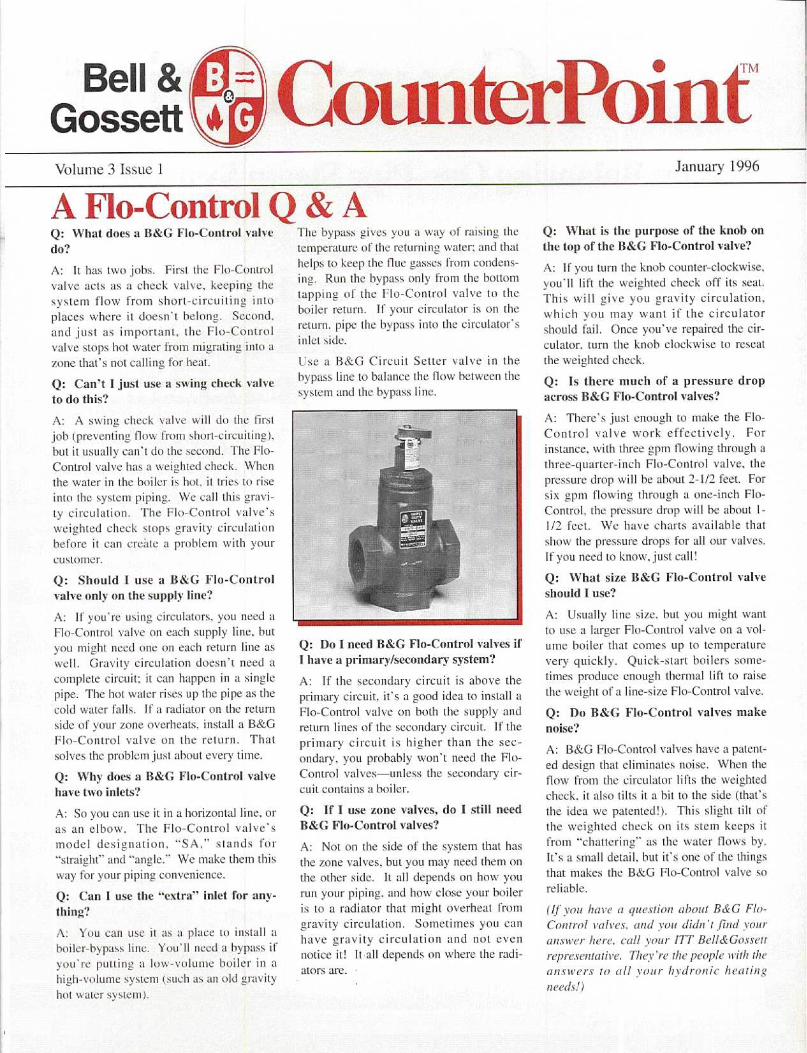
A Flo-Control Q & AQ : What does a B&G Flo-Control valvedo?
A : It has two jobs. First the Flu-Controlvalve acts as a check valve, keeping thesystem flow from short-circuiting intoplaces where it doesn't belong. Second .and just as important, the Flo-Controlvalve stops hot water from migrating into azone that's not calling for heat .
Q: Can't 1 just use a swing check valve
to do this?
A : A swing check valve will do the firstjob (preventing flow from short-circuiting>,but it usually can't do the second . The Flo-Control valve has a weighted check . Whenthe water in the boiler is hot . i t tries to riseinto the system piping . We call this gravi-ty circulation, The Flu-Control valve'sweighted check stops gravity circulationbefore it can create a problem with yourcustomer.
Q: Should I use a B&G Flu-Controlvalve only on the supply line?
A : If you're using circulators, you need aFIn-Control valve on each supply line, butyou might need one on each return line aswell . Gravity circulation doesn't need acomplete circuit : it can happen in a singlepipe. . The hot water rises up the pipe as thecold water falls . If a radiator on the returnside of your zone overheats, install a B&GFlo-Control valve on the return . Thatsolves the problem just about every time .
Q : Why does a B&G Flo-Control valvehave two inlets?
A : So you can use it in a horizontal line, oras an elbow. The Flo-Control valve'smodel designation, "Sa " stands for"straight" and "angle ." We stake theta thisway for your piping convenience .
Q: Can I use the "extra" inlet for any-thing?
A : You can use it as a place Lo install aboiler-bypass line . You'll need a bypass ifyou're putting a low-volume boiler in ahigh-volume system (such as an old gravityhot water system) .
CounlierPointThe bypass gives you a way of raisin, thetemperature of the returning water; and thathelps to keep the flue gasses from condens-ing. Run the bypass only from the bottomtapping of the Flu-Control valve to theboiler return . If your circulator is on thereturn . pipe the hypass into the circulator'sinlet side .
Usee a B&G Circuit Setter valve in thebypass line to balance the flow between thesystem and the bypass line . .
Q: Do 1 need B&G Flo-Control valves ifI have a primary/secondary system?
A : If the secondary circuit is above theprimary circuit, it's a good idea to install aFlo-Control valve on both the supply andreturn lines of the secondary circuit . If theprimary circuit is higher than the sec-ondary, you probably won't need the Flo-Control valves unless the secondary cir-cuit contains a boiler .
Q : If I use zone valves, do I still needB&G Flo-Control valves?
A: Not on the side of the system that hasthe zone valves, but you may need them onthe other side. It all depends on hnw yourun your piping, and how close your boileris to a radiator that might overheat fromgravity circulation . Sometimes you canhave gravity circulation and not evennotice it! It all depends on where the radi-ators are .
January 1996
Q: What is the purpose of the knob onthe top of the B&G Flo-Control valve?
A : If you turn thee knob counter-clockwise,you'll lift the weighted check off its seat .This will give you gravity circulation,which you may want if the circulatorshould fail. Once you've repaired the cir-culator. turn the knob clockwise to resealthe weighted check .
Q: Is there much of a pressure dropacross B&G Flo-Control valves?
A: There's just enough to make the Flo-Control valve work effectively . Forinstance.. with three gptn flowing through athree-quarter-inch Flo-Control valve., thepressure drop will be about 2-1/2 feet . Forsix gptn flowing through a one-inch Flo-Control, the pressure drop will hee about I-1/2 feet . We have charts available thatshow the pressure. drops for all our valves .If you need to know . just call!
Q: What size B&G Flo-Control valveshould I use?
A: Usually line size, but you might wattto use a larger Fln-Control valve on a vol-
nine boiler that comes up to temperaturevery quickly . Quick-start boilers sonte-tinles produce enough thermal lift to raisethe weight of a line-size Flu-Control valve,
Q : Do B&G Flo-Control valves makenoise?
A : B&G Flo-Control valves have a patent-ed design that eliminates noise . When theflow from the circulator lifts the weightedcheck, it also tilts it a bit to the side (that'sthe idea we patented!). Till ,, slight tilt ofthe weighted check on its stern keeps itfroth "chattering" as the water flows by .It's a small detail, but it's one of thee thingsthat makes the B&G Flo-Control valve soreliable .
(If yota home a yues'lirxa about B&G Flo-Control mires . and von didn't .finnd Vole),anstl'rr here, call mar ITT BclldGosscttrepresentative. They're the people tritlr theaaasiters to till voter bydrnaaic healingneeds!)

Volume 3 Issue 2
One. of our reps told us a story ahout howhe was standing at a wholesaler's counterone day when a contractor walked in . Thecontractor was carrying an old B&GSeries 100 hearing assembly. Since thepart was painted that distinctive blue,our puy knew right away that the pumphad come from a Weil-McLain "pack-aged" boiler. Our friends at Weil-McLain paint just about everything ontheir boilers that special blue .
The contractor set the hearing assem-bly down on the crowded counter . "1need one of these ." he said to the coun-terman . The counterman picked up thepart and slowly looked it over . Our repsilently recited the. part number to him-self. Eleven eighty-eight forty-four, hethought . That's the most common bearingassembly of all . There are millions of themout there in the field .
But then the counterman set the bearingassembly down and sadly frowned at thecontractor . "Sorry," lie said, "but we onlyhave the red ones ."
The contractor shook his head in disgust,and said, "Nuts! Now 1 gotta go sonic placeelse." He started to walk out, but theycaught him in time. Lucky thing!
Don't lie CluclessThe next clay . a wholesaler friend called totell us about a contractor who wanted tobuy a replacement B&G pump .
"Which pump is it'.'" the wholesaler asked .
"I don't know," the contractor answered .
"Well, what can you tell me about it'?" thewholesaler asked . trying to pry out a cluethat would help him solve the mystery,
"Its red," the contractor said .
"Hey, that's a start!" the wholesaler said,encouragingly . "Can you tell me anythingelse about the pump?""Yeah." the contractor said . "it's broke ."
We know that life in the field can be diffi-cult at times, and that information is oftenhard to come by. We also know that thereare powerful forces out there that causeidentification tags to vanish in the night .It's not easy being a contractor, especiallywhen you have to replace an old pump or
thunlerPoint'Even If It's Blue, We'll Still Have Parts For You!
an old part .
You may not always find enough infornia-tion . but if you pick up on the right clues,
Even if it's painted some color other than red, theB&G Series 100 remains an industry standard .
your wholesaler and your B&G rep canalmost always figure out what you need .
Here are. the questions they'll ask you .
Is there a itautneplate?This, of course, would make life so simple!Look on that hase.plate or the bearingassembly for an 1D tag, and write down allthe numbers you can find .
Is the pump base-mounted or lining?So there's no nameplate . Don't worrybecause centrifugal pumps will alwayswind up in one of two basic families .Some sit on the floor ; others hang in thepipes. Which is it in your case? This is agreat place to start, because the answer willnarrow the field by half .
What is the motor's horsepower andvoltage?We often punch this information right intothe motor. That makes it harder for thoseforces in the night to remove, so if you canget it for us, it'll help .
Does the pump have a coupler betweenthe bearing assembly and the motor?Here. again we wind up with two familiesof pumps . Yours has to he in one or theother. Some pumps have couplers ; somedon't. It's all easy question, and it gets useven closer to that final answer .
Does the coupler have springs?The larger pumps use couplers without
April 1996
springs. The smaller (usual€y fractional-horsepower) ptnnps are the ones that havethe spring couplers. We can tell a lot bythat coupler, so check it out .
Which was does the mot or spin?Imagine you're sitting on the motor, andholding onto the pipe with both hands .Look down . Does the motor spin clock-Wise or counterclockwise? By knowingthis, we can tell whether you have abooster or a centrifugal pump, and thathelps us a lot .
Is the pump oil or grease lubricated?A,ain, this information narrows thefield . And don't think that just becausethe pump sits on the floor, it has to begrease-lubricated . We once made a line
of base-mounted pumps we. called the."Universal." They were big, and they saton the floor, but they also had oil-lubricat-ed, sleeve bearings . We sold many of theseto schools and libraries across the U .S .
Can you read any casting numbers?These numbers go on at the foundry . Theymay not make sense to you, but they canhelp us identify what you're. dealing with .And they're very tough to remove!
What size is the inlet and outlet piping?Look at the flanges, not at the pipe runninginto and out of the pump. Give its the sizeof the. flanges . and we'll use this with theother information you've provided to reallyzero in on that pump .
What is the end-to-end dimension fromthe volute to the back of the motor? Andwhat is the lace-to-Face dimensionbetween the llanges?When all else fails, we took to this impor-tant information . By knowing the physicalsize of the pump, we can hurt it down bythese two critical dimensions .
So don't worry! When it comes to pumpsand parts, we'll niwa's he able to figure itout . All you have to do is take a fewmoments and gather the right clues for us .
And remember. if your bearing assembly • isblue . or sonic color other than that beautifulB&G red, don't give up! Lots of peoplepaint B&-(j products colors other than ourfamous B&G red .

Volume 3 issue 3
Life may have been simpler before the inven-tion of the circulator, bill those old gravity hotwater systems of yesteryear sure weren't'.Gravity systems had slow response lime .. nocontrol. plus poor circulation in radiation . Theaddition of the booster pump increased circula-tion and provided rapid response and morecomplete control . But there are still manythings you need to consider besides using abooster pump to increase circulation .
Supply and return - The old ,cavity systemboilers had multiple tappings that were usedfor multiple circuits direct off the boiler toincrease circulation, When you convert toforced ]low you want only one supply and onereturn, so boilers should he cross connected forfull use of the boiler and better efficiency, andthe: piping around the boiler should he reducedto the flow required according to the radiationBTU load. Measurement ol'the longest circuitwill determine the pressure drop of the system- most buildings are either rectangles orsquares, so measure the length and width andmultiply by 2 to get the approximate length ofthe longest circuit . The pressure. drop and flowwill then determine pump size . Note that thismethod applies to I - or 2-story residential only .
Orifice plates - In many of the old systems,orifice plates were used to balance the flowbetween the. first and second floor . Because,hot water rises and takes the path of least resis-tance (which would occur in upper floor radia-tion) . a small hole was drilled into these platesto increase the pressure drop of the secondfloor radiation and create flow in the . first floorradiation, in converting to forced flow it mayhe advisable to reverse the location of the ori-fice plates from the second floor radiation tothe. first floor to increase the resistance so flowwill occur equally in each piece of radiation .
Radiator valves - In old systems with radiatorvalves, the valves do not have to be changed .These globe type valves corn be used to balanceeach individual radiator, and in multiple circuitsystems each circuit should he balanced . ft iseasy to get short circuiting in older systemsbecause of the larger diameter pipes, and lowresistance in some circuits will cause a tremen-dous flow unbalance causing less heat in somecircuits and more than needed in others .
Distribution piping - The existing distributionpiping can he used when changes are trade atthe boiler, however, if the existing boiler is tobe used, remember that it holds a great deal of
Gravity Hot Water - Conversion to Forced Flowwater compared to newerboilers . If a new boiler is tobe installed, the piping watervolume will be much greaterthan boiler water volume . Toprevent possible water ham-mer, thermal shock and fluegas condensation in the boil-er, it is recommended youinstall a bypass line thatmixes hot supply water withcolder water from the. systemand modulates return waterfrom the system to the boiler .
Pressurization - Older gravi-ty systems are open to theatmosphere and cannot be.p ressurized . s o an openexpansion tank was used totake up the expansion ofwater as it was heated in thesystem (maximum operatingtemperature was 181)degrees) . If the old system ischanged to a closed system,you must put in a compres-sion tank (a closed tank) totake up the expansion andpressure of the water as it is heated .
Air control - In a forced flow installation, anair control system would have to be installed tocontrol the air in the . system once it is closed .An air separator and a standard or pressurizedtank could be used .
Relief valves - Gravity systems did not have arelief valve on the boiler . Don't forget thatclosing the system requires a safety relief valverated at the maximum boiler operating pressureand gross BTU output load of the boiler .
Flow control - Valves are needed to preventgravity flow and if they are not used, you willget flow in the system whether or not the punpis on . Old systems operated on gravity flow{w,and Without flow control, will be subject tooverheating or loss of control .
~111
In _111-11h
Typical old gravity system .
September 1996
Thermostats - In oldersystems, the boilermaintained a set temper-ature all the time with anaquastat controlling theburner . In new systems,a two-stare thermostatcan activate the boilerand pump to control thesystem . For greaterenergy savings, the boil-er doesn't have to bekept at a constant tem-perature, but it shouldonly he called into oper-ation when needed .
Some final reminders -Before raising watertemperature, know thatthe boiler is rated at acertain capacity perhour, and that raising thewater temperature doesnot increase the outputof (lie boiler (it willincrease the output ofthe radiation if the boilerhas the capability) .
If' you're changing the type of radiation in am,part of the. building, put it on a separate zone .Convector baseboard and free-standing radia-tion have. different characteristics of heat trans-fer and capacity : convector baseboard heals upfast and cools down rapidly, while old radia-tion with more water and a greater metal massheats up slowly and holds heat longer .
There are many factors which must he consid-ered in conversion jobs . and common senseshould be applied with good judgment indesigning a conversion from gravity to forcedflow. When you have questions about gravityhot water. or any hydronic system (old ornew!) You'll find the answers at your BellGossett representative's . They're there to ( help .
so give them a call!
Converted gravity to forced system .
Compliments of:
TIIERMOFLO EQUIPMENT COMPANY, Mr.3233 Babcock BoulevardPittsburgh, PA 15237Phone (412) 366-2012
41
41

Volume 3 Issue 4
New Solution to an Age-Old ProblemAA sk any heating/\~nian what is the
most Commoncause of hydronic heatingproblems . and he'll tellyou air! Air can be thesource of all kinds ofproblems includingunbalanced heating zonesdue to air binding . It is agreat insulator, reducingthe heat output ofbaseboard zones . whichin turn creates higher fuelhills for your customer_It can also damage pumpseals and bearing
B&GHYDRO-FLO" moduleassemblies. But the mostcommon complaint of air in hydronicsystems is the gurgling, "waterfall"-likenoises that result in a service call to yourcustomer .
Did you ever think about where this aircomes front or why it always seems tomake its way into the bedroom zones"Well, it conies in with the cold make-upwater used to fill the system. You can't seethis air because it is dissolved in the coldwater (like sugar in coffee!) . But as soonas this cold water is heated by the boiler,the air comes out of solution in the form ofair bubbles. You see, hot water can't holdas much air in solution as cold water . Ifthese air bubbles aren't caught right at theboiler, the circulator will send them flyingout to the piping system at a speed of 4-5feet per second . This explains why, whenyou place float vents throughout thesystem . they do nothing to solve theproblem. The air just whips past thesevents as if they weren't even installed .
The answer is to install a good air separatorright near the outlet side of the boiler tocatch these "bubbles ."
Typically, the traditional °airscoop" hasbeen installed incorrectly. which only addsto the problem . On most of these jobs, youend up going back and purging the air outof the system . Of Course the water used topurge the system is cold and holding alarge amount of air in solution. Once
Counterpoint
heated, the air again comes out of solutionin the form of bubbles and makes its wayout to the system . Eventually you'll get thecall complaining about the "air problem"again and you'll go back to purge it out!This is like a dog chasing his tail!
There's Got to be aBetter Way!
Bell & Gossett recently introduced aconcept on how to effectively piperesidential hydronic boilers . It is called theHYDRO-FLO® module, and it provides acost-effective method to assure the systemwill operate free of air-related problems,while providing a quiet, efficient hydronicsystem . The HYDRO-FLO modulereduces the contractor's installation timeand the components can be easily serviced!
The Hydro-Flo ModuleThe heart of the HYDRO-FLO moduleconsists of B&G's EAS which is our newenhanced air separator . This device usesa coalescing medium which acts like
December 1996
"thousands of little lingers" snatching theair bubbles out of the water as it flowsthrough the unit . In addition, they surroundthe coalescing medium with a diffuserplate . This plate spreads the water across agreater percentage of these "fingers,"increasing their effectiveness .
From an installer's perspective, what'sunique about this unit is its inlets and oneoutlet (like our SA Flo Control valves .)This means you can pipe the EAS right intothe vertical supply riser coming up out ofyour boiler. The air separator is soeffective . n o minimum pipe diameters arerequired to install it. On the outletconnection you should install yoursystem/zoning circulators and Flo-Controlvalves or system circulator and zonevalves . Instead of plugging the horizontalinlet port, you can locate the diaphragmcompression tank, a pressure reducingvalve and a pressure gauge, all installed ona conventional piping cross .
Easy to Install,Easy to Service!
By simply installing a boiler drain in a teefitting on the supply riser out of the boiler,and service valves on each zone, you canPOWER PURGE"", ' individual zones fromthis one drain and hose connection . Don'tforget to locate the boiler drain below theEAS and the supply riser's service valve .Now when it comes time to service any ofthe hydronic components, simply closeeach zone's service vale and the supplyriser's valve, and you have access to all thecomponents without draining down thesystem!
If you need more information or have anyquestions about HYDRO-FLO® . contactyour local Bell & Gossett representative .
Compliments of :
Bell &GossettVolume 4 Issue I
The Benefits of Parallel Pumping are "Unparalleled"
T he benefits of parallel pumping seemto be known only in the engineeringcommunity . For some reason our
industry thinks that parallel pumping is onlyfor large flow rate applications such aschilled water distribution systems . This isunfortunate because there are many benefitsto be realized by the "smaller" applications .
In fact, once you understand parallelpumping and how toapply it properly. youwill find that you don'tneed to use bigger in-line or base-mountedpumps as often becausetwo smaller pumps inparallel will handle thejob just as well . Also, ifyou get stuck in a jamand your supply housedoesn't have that onebig pump you need todo the job. b y applyingparallel pumping youwill be able to use twosmaller stock pumps .
Whun two pumps arebetter than one
Parallel pumping involvesinstalling two circulating pumps in a pipingsystem in parallel with each other . Whenselected properly, each circulator will pumphalf of the total required flow rate at thedesign head loss. This means that eachpump is capable of pumping half of thegallons per minute needed at the totaldesigned pressure drop for an application .
For example, if you had a system with aheat loss of 200,000 Btulh and youcalculated the flow rate based upon a designtemperature drop of 20 °F, you would needto pump 20 gpm . And for argument's sake,let's say that at this flow rate, the systemhas a total pressure drop of 8' . At this pointyou have several choices :I l you can select one pump that is capableof meeting the design conditions,2) you can also pick one additional pump as100% stand-by, or3) you can pick two smaller pumps in
321
CounterPoint~~
parallel to meet the condition .
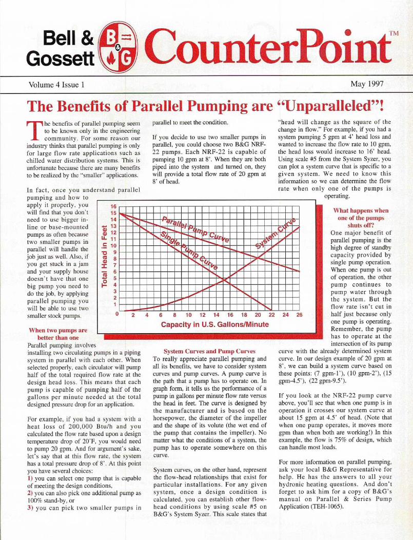
If you decide to use two smaller pumps inparallel, you could choose two B&G NRF-22 pumps. Each NRF-22 is capable ofpumping 10 gpm at 8' . When they are bothpiped into the system and turned on, theywill provide a total flow rate of 20 gpm at8' of head .
\~/∎/11/U∎∎∎∎/•U∎∎∎∎∎/U∎/U
∎∎∎∎∎∎∎∎∎\i~7/∎∎∎∎i 5F •∎∎∎∎
6
8
10 12 14 16 18 20 22
Capacity in U.S. Gallons/Minute
System Curves and Pump CurvesTo really appreciate parallel pumping andall its benefits, we have to consider systemcurves and pump curves. A pump curve isthe path that a pump has to operate on . Ingraph form, it tells us the performance of apump in gallons per minute flow rate versusthe head in feet. The curve is designed bythe manufacturer and is based on thehorsepower, the diameter of the impellerand the shape of its volute (the wet end ofthe pump that contains the impeller) . Nomatter what the conditions of a system, thepump has to operate somewhere on thiscurve .
System curves, on the other hand, representthe flow-head relationships that exist forparticular installations . For any givensystem, once a design condition iscalculated, you can establish other flow-head conditions by using scale #5 onB&G's System Syzer . This scale states that
24 26
May 1997
"head will change as the square of thechange in flow." For example. if you had asystem pumping 5 gpm at 4' head loss andwanted to increase the flow rate to 10 gpm,the head loss would increase to 16' head .Using scale #5 from the System Syzer, youcan plot a system curve that is specific to agiven system. We need to know thisinformation so we can determine the flowrate when only one of the pumps is
operating.
What happens whenone of the pumps
shuts ofl?One major benefit ofparallel pumping is thehigh degree of standbycapacity provided bysingle pump operation .When one pump is outof operation, the otherpump continues topump water throughthe system . But theflow rate isn't cut inhalf just because onlyone pump is operating .Remember, the pumphas to operate at theintersection of its pump
curve with the already determined systemcurve. In our design example of 20 gpm at8', we can build a system curve based onthese points : (7 gpm-1'), (10 gpm-2'), (15gpm-4.5'), (22 gpm-9 .5') .
If you look at the NRF-22 pump curveabove, you'll see that when one pump is inoperation it crosses our system curve atabout 15 gpm at 4.5' of head. (Note thatwhen one pump operates . i t moves moregpm than when both are working!) In thisexample, the flow is 75% of design, whichcan handle most loads .
For more information on parallel pumping,ask your local B&G Representative forhelp . He has the answers to all yourhydronic heating questions . And don'tforget to ask him for a copy of B&G'smanual on Parallel & Series PumpApplication (TEH- 1065) .

Bell &GossettVolume 4 Issue 2
Primary-Secondary Pumping "Rules of Thumb"Primary-secondary pumping has beenaround since 1954 . Most of theapplications for this pumpingtechnique, pioneered by Bell &Gossett, have been in large commercialsystems such as chilled water campussystems, dual temperature chant*e-oversystems, and freeze protection formake-up air systems .
In recent years though, there has beenrenewed interest in this technique forsmaller, light commercial - and evenresidential - applications . In fact,multiple hot water boiler applications,When installed correctly, must usepriInary-secondary pumping .
Radiant in-floor heating has becomevery popular too. To meet the designWater temperatures of radiant systems .the mixing of some cooler return waterwith some hot water front a cast ironboiler must take place, and the mosteffective. method for accomplishing thisis through primary-secondary pumping .Most residential cast iron boilermanufacturers have limitations on thewater temperature maintained in theirboiler, hut, when using these boilerswith radiant heating systems, primary-secondary pumping is an effective wayto raise the return water's temperature .
In the late '70s and early 'SOs .commercial buildings such asapartments and smaller schoolsincorporated a method of reset throughthe use of a 3-way motorized valve .Based upon outdoor temperatures . thevalve would reposition itself to deliverjust the right amount of heat to satisfythe building's heat loss. However, theproblem with a lot of these installationswas that there was no means providedfur measuring the relur'n temperature ofthe water entering the boiler . Undercertain conditions, a tremendousamount of cool water Would enter theboiler, causing thermal shock and
Counterpointhttp://fhs.ittind.com
possibly cracking boiler sections .However, a simple boiler loop pump,piped using primary-secondarymethods. would prevent this problem .
Primary-secondary pumping is simplein theory as well as operation . Il isbased on a simple fact : when twocircuits are iulercofrriecled, flow in onewill not cause flow in the other 1/' thepressure droll in the ppinS common toboth is eliminated.
RULES OF THUMB
#1 THE COMMON PIPEThe key to all primary-secondary applications isthe use of a common pipewhich interconnects theprimary and secondarycircuits . The length ofthis pipe should be keptvery short in order tokeep the pressure dropvery low, and the supplyand return tees to thesecondary circuit shouldbe a maximum of fourpipe diameters apart . Bykeeping the pressure drop very low,water that is flowing in the primaryloop will not flow into the secondarycircuit until its circulator turns on .
#2 THE SECONDARYCIRCULATORA separate circulator is installed in thesecondarv circuit to establish flow . Thiscirculator is sized to move the flow rateand to overcome the pressure drop of itscircuit only . The circulator should belocated so it is pumping away from the"common piping" and discharging intothe secondary circuit. This causes anincrease in pressure in the secondarycircuit rather than a reduction in pressurewhich Would occur if the pump werelocated on thee return pumping towardsthe common pipe .
October 1997
#3 TIII: LAW OI' THE TEEThis rule determines the flow rate anddirection of flow that occurs in commonpiping . It is based on the relationship ofthe primary and secondary flow rates .and there arc three possibilities toevaluate :
1 I Primary flow more than secondary
2 f Primary flow equal to secondary
3) Primary flow less than secondary
This rule of thumb is best described by asimple statement : flow into a tee ml{stequal /lair' m1'av /ronl the tee.
Tee "B"/ Primary Return 150 G.P.M .
ICommon Piping-Flow & Direction
\ Primary
\ PrimarySupply Main
Return Main
#4 FLO-CONTROL. VALVESFlo-Control valves are reconlnlended toprevent any flow into the secondarycircuit induced by either the slightestpressure drop that may exist on thecommon pipe or by gravity heads .Because gravity flow can occur within asingle pipe, two Flo-Control valves arebest. one on the supply and one on thereturn . However, if the secondarycircuit's return is underslung, only onevalve is needed .
For more detailed information onprimary-secondary pumping . contactyour local B&G representative. They arewell "primed" on this and many otherhydronic subjects . Ask for B&G'sbulletin TE-H-775 Primary-SecondaryPumping, Application Manual .

Volume 5 Issue 1
The Shocking Facts About Sudden Thermal ChangesWhen a modern hot water boiler experi-ences thermal shock . the cause is oftenignored and written off as defective mate-rial or workmanship . But there is always areason why a boiler (cast iron, steel firetube or steel water tube) becomes thermal-ly shocked .
"Boiler Thermal Shock" can be looselydefined as sudden thermal changes thatoccur within the boiler causing rapid anduneven contractions of the boiler's cast ironor steel material. An example is placing acold glass under hot water--the glasscracks because of the extreme temperaturechange. In thermally shocked boilers, thefractures or cracks occur where the tem-perature difference is greatest-usually inthe back of the boiler near the nipple jointsor the furnace area where the cold waterenters . Surfaces exposed to cold water arecontracting while surfaces exposed to fireare expanding .
Causes of Boiler Thermal ShockSeveral conditions can contribute to boilerstressing and eventual boiler shock. Allinvolve introducing excessively low tem-perature water, or cool temperature water athigh flow rates, into the hot boiler :
&A Returning water at too low a tempera-ture
r Cool return water at too great a flow
,r Firing the boiler and heating up waterbefore system circulator is turned on
V Moving the burner into high fire withboiler water at too low a temperature
Influence of System Designs• Systems incorporating night setbackand/or weekend shutdown are designed tosave energy, but turning down or shuttingoff the building's temperature causes prob-lems when all the zone valves and pumpscome back on delivering room temperaturewater to a hot boiler .
•
Dual temperature changeover systems
Counterpoint"http://fhs.ittind.com
can experience boiler problems when thesystem tries to change over from a cool- .ing demand to heating . The pipingsystem and terminal units are filled with50-60°F water and the boiler may contain180°F water .
• Heat pump loop systems typicallyrequire some form of supplementary heatto maintain supply water loop tempera-tures when the outdoor temperatureapproaches design conditions . Boilers arethe common source for this additionalheat, but design loop temperatures are aslow as 70-85 °F, while most commercialcast iron boilers don't operate below 140-150°F.
• Heating systems that have boilers main-taining temperature without flow aresusceptible to thermal shock by suddenchanges in flow due to pump operation .
• The most common cause of thermalshock is a system that incorporates outdoorreset with 3-way valves while the boilermaintains temperature. The boiler is at180°F, but based on outdoor temperature,the system may require only I00°F. Thereturn temperature can be as low as 90°F,which can cause a 90°F differential acrossthe boiler. (Remember the cold glass andhot water!) Most cast iron boiler manufac-turers would like to see no more than a40-50°F temperature difference betweenthe boiler's return temperature and leavingtemperature .
Preventing Thermal ShockWaterside thermal shock can be preventedby controlling the load imposed on the boil-er. Boiler load is a function of flow rateand temperature difference, and one of themost effective methods is to create a boil-er loop separate from the system and pumpit with its own circulator . Since the flowrate is constant, the temperature differenceacross the boiler becomes the measurementof the boiler's load, and if the boiler ismaintaining temperature, the return water's
February 1998
3-Way Valve in Boiler Looptemperature will determine the boiler load .
Control against "boiler shock" involvescontrol of the incoming cold water flowrate so that the boiler's temperature ischanged slowly . By installing the 3-wayvalve in the boiler loop . the outdoor resetcan control the amount of hot water that isintroduced into the system based upon areset schedule . More importantly. the resetcontroller can measure the return tempera-ture entering the boiler. If watertemperature becomes too low for the boil-er manufacturer's recommendations, the3-way valve will close off the system loop.Hot water from the boiler will then bepumped right back into the return, raisingthe water temperature entering the boiler .The 3-way valve and controller will floatback and forth, resetting the supply water tothe system while protecting the boiler fromcold water.
The best method for interconnecting thisboiler loop with the system loop is throughprimary/secondary pumping techniques .By keeping the supply and return tees closetogether, the pressure drop in the commonpiping is kept to a minimum . This allowsdifferent size pumps to co-exist in the sys-tem without affecting each other as well aspreventing ghost flows from occurringfrom one loop into the other .
For more information on this or anyhydronic subject, contact your local Bell &Gossett representative . They can helpsoothe your shock, so give them a call .

Volume 5 Issue 2
Whether you are troubleshooting an oldforced hot water system or installing a newone, you must consider air that will be pre-sent in the system. The two basic types ofair management in hydronic systems areair control and air elimination, Wheninstalled properly, both are effective at pre-venting air problems .
Air ControlThe air control method has been around formore than 40 years and has proven quitesuccessful. It uses a standard steel tank inwhich the air and water actually touch . Theair inside the tank acts like a spring push-ing down on the water to keep the systempressurized . The air cushion in the tank iscompressed by the heated water thatexpands into the steel tank . The compress-in- of the air in the tank causes the systempressure to increase, but through propersizing methods, the pressure increasewon't reach the relief valve's setting .Without this cushion of air, the pressure inthe system will rise rapidly when the wateris heated, causing the relief valve to dumpwater onto the floor. Therefore, for thissystem to work properly, it is importantthat a cushion of air bee maintained in thecompression tank .
Unfortunately, one of the characteristics ofthis system is that the water and air "see"each other inside the compression tank .We know that water can absorb air intosolution, the hotter the water and the low-er the pressure, the more air will come outof solution in the form of bubbles, as thewater temperature cools down or the pres-sure increases, the water will be able toabsorb more air. On the next firing cycle,if the air that comes out of solution isn'tdirected back into the compression tank-and is instead vented out of thesvstem-the tank will start to lose its cush-ion. Then it is only a matter of time beforethe tank becomes waterlogged .
For an air control system to work proper-
0
ounterPoint"h ttp://fhs.ittind.com
ly, it is important to use some type of airseparating device that "catches" the airwhen it comes out of solution and thenimmediately directs it back up into thesteel compression tank . Do not use auto-matic vents in an air control system. Theywill do a good job of venting air out of thesystem that really belongs back in theexpansion tank . Also, don't forget to installa device known as an Airtrol Tank Fitting(ATF:) . It does a great job of preventing thecooler. "air-tilled" water from sliding outof the tank in gravity flow. Finally, makesure the line connecting the tank to the airseparator is pitched up towards the tankwithout any pockets or places where theair can get trapped .
Air EliminationThe air elimination method has alsoproved to be quite effective. This methoduses a diaphragm or bladder-style expan-sion tank instead of a standard steel tank .The tank is pre-charged with air on oneside of the membrane that separates thesystem water from the air. Any air that isreleased from the water needs to be vent-ed out of the system through automatic airvents. This tank style also gives you a lotof flexibility regarding installations . Whena standard steel tank is used, it is necessaryto locate the tank somewhere above the airseparator so that the separated air can flowby bouyancy back into the tank ; however
November 1998
Proper Air Management in a ydr is SystemTypical Applications
3&1,ARIPLL:4N$ FITTING
7 . 11-L
R e , FREASVRE __~RE000ING VALVE
ro66G?SME i
1A
Model FAS with Conventional Compression Tank
'.i LnJC3Jcvnwe
floc D ;Ar-RncidEXPANSION 7ANK
nas rAMr 33331,RE, IF- 'A. cr
Model [AS with Pressurized Expansion Tank
the diaphragm tank can be located any-where because it already has a charge ofair in the tank .
The air pressure in the tank must be pre-charged to the same pressure as thesystem's fill pressure . When the tank isunder-charged, cold system water willenter the tank even before the boiler hasheated up the water. The result is an under-sized tank causing the relief valve todischarge water onto the floor_ Whenchecking an existing tank's air char,re,make sure you isolate the tank from thesystem. If you don't, you wilt just read thepressure of the system at the point wherethe tank is connected .
.RELIEF1111EFj
PJMP
An effective air separator, such as theB&G EAS (see illustrations above), is alsovery important for successful air elimina-tion, the difference is that now all of theseparated air must be vented out through ahigh capacity automatic vent .
Both methods of air management haveproven to be quite successful . but theymust be installed properly to work . If youhave awry questions regarding air manage-ment in hydronic systems . contact yourlocal Bell & Gossett representative. Theyare well trained in all aspects of hydronics .Ask for a copy of B&G's training manualTEN-1 196. Air Management .

Volume 6 Issue I
All Mixed UpQuestions & Answers on MixingMethods Used in Hydronic Heating14''hat is Mixing? Mixing, is when a portionof return water from the system is "mixed"with a portion of hot water from the boilerto supply a specific water temperature thatis lower than the boiler temperature butwarmer than the return tcniperature .
What methods are used for mixing?There are two basic mixing methods : mix-ing valves which consist of three-way andfour-way valves . and injection mixing Whichuses either two-way valves or injectionpumps .
What is the difference between eachmethod? A three-way mixiniz valve hasthree ports and a four-way valve has fourports . Mixing blends cooler return water intoone of the valve's ports with hot water thatis entering another port . The two tenipera-tures blend and exit the supply port. With afour-way va[ve . any of the return water thatisn't used to mix with the ]tot water isreturned back to the boiler. Injection mixinginjects bursts of hot water into a constantlycirculating loop. A two-way valve opens andcloses . or a pump's speed is changed . tointroduce the right amount of heat .
Why frould someone use mixing in ahy'dronie system? Three major uses, for:
• Radiant heating that requires lower watertemperatures than most boilers can producewithout experiencing flue gas condensation_
• Outdoor reset. By matching the Supply
water temperature to the load on the build-ing, the healing system will operate moreefficiently . Unfortunately, the required watertemperatures are lower than most boilers aredesigned to handle .
• Hydronic systems that incorporate dif-ferent types of heat emitters such as in-floorheating, panel radiation . cast-iron radiationand hydra-air coi Is . Each type requires a dif-ferent supply temperature but all receive
Counterpoint"www.bellgossett.com
their water from thesame boiler. MI
L[IARUPW LUN•w nuRLIIL,,F[
What happens if Iuse only onepump with mymixing device'!There will be onlyOne mixing point .This will controlthe supply watertemperature for that particular zone, but notthe temperature of the water returning to theboiler . Also, the flow rate through the boil-er will vary, decreasing the boiler'sC . .icicncv .
Why should I use two pumps? Using twopumps, with a mixing device, establishestwo mixing points . This protects the boilerby controlling the temperature of the return-ing water. The second pump also providesconstant flow through the boiler, improvingthe boiler's efficiency .
How should I pipe the mixing deviceand the two pumps? Use primary/sec-ondary pumping so the two pumps will notoperate in series with each other . Anotherbenefit of primary/secondary pumping : youcan efficiently size the mixing device .
Why should I be concerned with thetemperature of the water returning tothe boiler? It' you are using a non-con-densing style boiler, it is important that theflue gases released front the combustionprocess be vented Out of the boiler. Whenthe water in the boiler is at a temperaturebelow the dewpoint of the flue gases, thesegases will condense back to water insidee theboiler . The results can be very damaging .Boiler thermal shock is another reason forcontrolling the return temperature .
'i%'hat is line gas condensation? Duringcombustion of the fuel . many by-productsare formed including carbon dioxide, sul-
OUT000I AIRI
TEMP SENSOR".x-
A S...LMt0IF
rnh
T$7[E~ OEC'!f
--------------
.87AIR VENT
EAS
PRIMARYLOOP
May 1999
SECONDARYLOOP
RETURN FROM_ SYSTEM
Primary/secondary variable speed injection pumping for radi-ant floor panel systems .
phur compounds and water vapor. Lowreturn water temperatures will cause thecompounds to condense. forming corrosiveliquids in the boiler stack and heat exchang-ers . The amount of damage that will occurdepends on the design and materials of con-struction used in the boiler, as well as thespecific compounds in the flue gas . Alwayscheck with the boiler manufacturer to findthe minimum recommended return watertemperature .
When using a mixing device, how do Icalculate the flow rates to achieve thedesired mixed temper ture? The answercan be found in this example :
Radiant zone load = 50.000 Btu/11designed at 20' teniperaturc- drop .
Design radiant zone flow rate = 5-pin
Radiant design supply temperature =120'F (based upon 20'F temp, drop,return temp. of 100`F)
Boiler loop supply temperature = 180' F
The design temperature difference betweenthe two loops is 80'F so . . .
50.00080'F x 500 = 1 .25 gpn
This is the amount of 180'F boiler waterneeded to ;,mix" with 3.75 -pin of 100`Freturn water from the radiant cone to supply5 gpnn of 120'F water .
For answers to any hydronic heatingquestion. contact your Bell & Gossettrepresentative .

Volume 6 Issue 2
Trimming the Pump Impeller Can Cut CostsDetermining Flow and HeadThe pump is installed and running . but howdo you know if it is operating at its designpoint'? There is a simple way to check .Knowing that a pump will provide a certainflow at a given head, we can determine theepoint at which the pump is operating. Todetermine the head, a few gage readings willbe necessary . Take one reading from the suc-tion of the pump and one from the dischargeafter the system is balanced and with all thecontrol valves wide open . The differencebetween the two gage readings will give youthe head that the pump is providing . Remem-ber to convert your gage readings to feet ofhead. Knowing the head and the impellersize, you can determine the flow of the pump .
Now that we have the flow and head of thepump, let's see how close we are to thedesign point. Most often, the head will beless than what we. expected, and the flow willbe more. Why does this happen? There aremany reasons, but it does no good to blame .anyone. Let's just fix the problem .
SolutionsTrimming the impeller is one of best solu-tions . Before we can trim the impeller, weneed to determine where the pump is operat-ing. In the pump curve above, let's call point"D" the design point, and draw the systemcurve that corresponds with that design point .Point "A" is where we actually are, whichwe determined from our gage readings .Along with that is our actual system curve .Remember that we are concerned with theactual system curve . This shows us how oursystem operates, not how it was designed .Operational and desi In points are often com-pletely different .
We would like to be on the unmodified actu-al system curve . but where on that curve'? Ifour load has not changed and our heat trans-fer is the same . we want to be at our designflow. That is"l," the ideal point .
rl'rimming the ImpellerBut how do we get there? Although it's offour impeller curve, we can trim ourimpeller down to the right size . In this par-
CP0
ounter oint"www.bellgossett.com
240
60
40
20
020D 400 600 800
1000
1200
1400
1600 . 1CAPACITY IN U.S. GALLONS PEF MINUTE
to
2.
50
0
ticular case, our ideal impeller size fallsbetween 10-112" and I 1-112 (,actually aboutH") . "). Fortunately, trimming an impeller isnot too difficult or expensive, and in fact itpays for itself very quickly . Notice fromthe figure that when we trim our impellerwe lose some pump efficiency, but we'remore concerned about the cost of operatingour pump and that cost has droppedtremendously. In this case we have droppedfrom S5Hp to 40 Hp-that's a lot . Even ifyour electric rates are low and you don'toperate all year long, there is still the poten-tial for great energy savings .
Consider the SavingsLooking at the pump curve you can deter-mine the horsepower savings between thedifferent operating points, and if you knowkilowatt-hour costs you can figure your sav-ings. Once you get the cost savings per yearfor trimming the impeller, a simple paybackperiod can be determined to see if trimmingis economically feasible . Payback periods ofless than a year are not uncommon .
This example shows how adding a smallsafety factor can lead to a large energy cost
Pump performance curve .
November 1999
penalty . It also shows why it's not a goodidea to install a larger impeller for some high-er demand in the future, and in the interimclose down on the discharge valve . It is bet-ter to wait and buy a new impeller when theincreased need arrives in the future .
An impeller cannot be trimmed indefinitely .The further you trim the impeller, the lowerits efficiency becomes . Plus, you are nowgetting near the hub of the impeller eye . It isbest not to trim the impeller any smaller thanthe minimum size impeller that the manu-facturer shows on his pump curve .
There may he times when waiting for theimpeller to be trimmed is not possible forexample, when shutting down the systemthat the pump is supplying would be impos-sible or too costly . In that case you may wantto order an additional impeller and run theprocess until the new impeller can heinstalled . Lastly, remember to re-balance theimpeller after trimmingg .
For answers to any pump questions, con-tact your Bell & Gossett representative .They have the answers to all of yourquestions .
rawam AN[t CMAYRAGTF111STIC CUM
roll Sx8u1SYs armvuw MW me No. V9C9
>~ 1 r70 ..-r.
CURVES PASE0 ON SHOP TEST USING CLEAR COLE WAFER AT A TEMPERATURE ,' NOFDYER st f . PERFORMANCE IS COARAMTEEO AT INClCATEN OPERATIYG POINT ONLY .
rrorm I C-4Tp$1 iCCCi 5x6x15il2
~~~~~~~I~• IIII~tt•~[ti[ti•7~F~7I[tiRi a>t`aIr~llwEl•EI• .-- '+ftlf;
a~I~I1l1I~tt•1t~"Jr~l.I~.a1lltia=5h-_.%Wftit11%dhkN 7594
pox-!
~ir+r~r~7~i~
~i~I~Ii~Ia ;~Etat.~ r~~.n~•~r++~ll~r~rllawl~rr
-341 111 W1
(!~~===1aaal~rll/a1.al~

Volume 7 Issue 1
Top Ten Reasons Why Relief Valves Discharge11Waterlogged Steel CompressionTank. There are some heating systems
that still use the older steel compressiontanks to absorb the water that expandswhen heated. IF for sonic reason the tankloses its volume of air, it will be replacedwith an equal amount of water_ Unfortu-nately . water isn't compressible so whenthe boiler fires up, the expanding water triesto enter the tank and causes an immediateincrease in pressuree which causes the reliefvalve to discharge this excessive pressurebuild up .
2Pressure Reducing Valve is LeftOpened or Fails Open. Most systems
today use a pressure-reducing valve to filland pressurize the system . If scale or min-erals build up on its s eat . i t may fail in theopen position . Also, most of these valveshave a manual bypass feature to fast-fill asystem . 11' the bypassvalve is accidentally leftopen it will expose thesystem to street pressure,which normally exceedsthe boiler's pressurerelief valvetating .
3Diaphragm TankLoses Its Air
Charge. The air cushionin this type of tank isseparated from the sys-tem by a membrane .Unfortunately, the mem-brane is permeablewhich allows a smallportion of the air to enterthe system where it isvented out . As thisoccurs. the PRV noticesa drop in system pres-sure. and rightfully adds water to maintainthe appropriate system pressure . Of coursethe. diaphragm tank is slowly losing itscushion of air and finally one day, whenthe boiler heats up the water . the reliefvalve discharses onto the floor .
i 1
Counterpoint"www.bellgossett.com
/l Undersized Expansion Tank . These{tanks, whether the "old" steel or the
diaphragm style, have to be sized correctlyto do their job . If someone installs anundersized tank, the volume of the water inthe system will be too great for the tank tohandle. This will cause an immediate rise inpressure and the relief valve will open .
5 Undercharged Diaphragm Tank . It isvery important to size the tank correct-
ly and be sure that the pre-charge of air inthee tank snatches the system's fill pressure .If the air charge doesn't . then cold waterwill be allowed to enter the tank before theboiler even heatsthe water . Thiswill have the sameeffect as an under-sized tank,
Protection of Hot Water Space Heating Boilers
6Tankless Coil .A tankless coil
located inside theboiler
producesdomestic
hotwater. Eventuallythese coils candevelop leaksfrom corrosion
and aggressive water. Once this happens,the boiler and its relief valve are exposed tothe pressure of the cold water line . Nor-mally this pressure exceeds the valve'srating and the relief valve opens .
7 Faulty Aquastat. A faulty aquastat willallow the boiler water to reach exces-
sive temperatures . This causes the water toexpand beyond the recommended range oftank sizinu, guides and the result is a rise inpressure beyond the relief valve"s capacity .causing it to open .
QThe System's Static Fill PressureRequirements Approach the Boilers
Relief Valve Setting . With this condition .every time the boiler Fires, the relief valvewill open. It is very important that whenselecting a boiler for applications in tallbuildings the maximum pressure allowed by
the boiler manufacturer must begreater than that required by thesystem's fill pressure.
9 Improper Location of theExpansion Tank and System
Pump. 1f the expansion tank andhi`*h head system pump areinstalled on the return, the pump'spressure differential will he addedto the system's fill pressure . Thesetwo pressures, when added togeth-er, may exceed the relief Valve",setting .
IOSystems that IncorporateHigh Head Pumps and
Pressure Differential Valves. Inthe Spring and Fall, when most of
the zone valves in the system are closed,the pressure differential valve opens to pre-vent the circulator from building upexcessive head pressure . Unfortunately thispump head is now directed toward the boil-er and relief valve. 11' this head pressurecombined with the system's static pressureexceeds the relief valve's pressure, it willopen .
These are some of the inure common (andnot so common) situations that can cause arelief valve to discharge. For expert helpwith questions or problems you may havewith any hydronic system, contact yourlocal Bell & Gossett representative .
April 2000
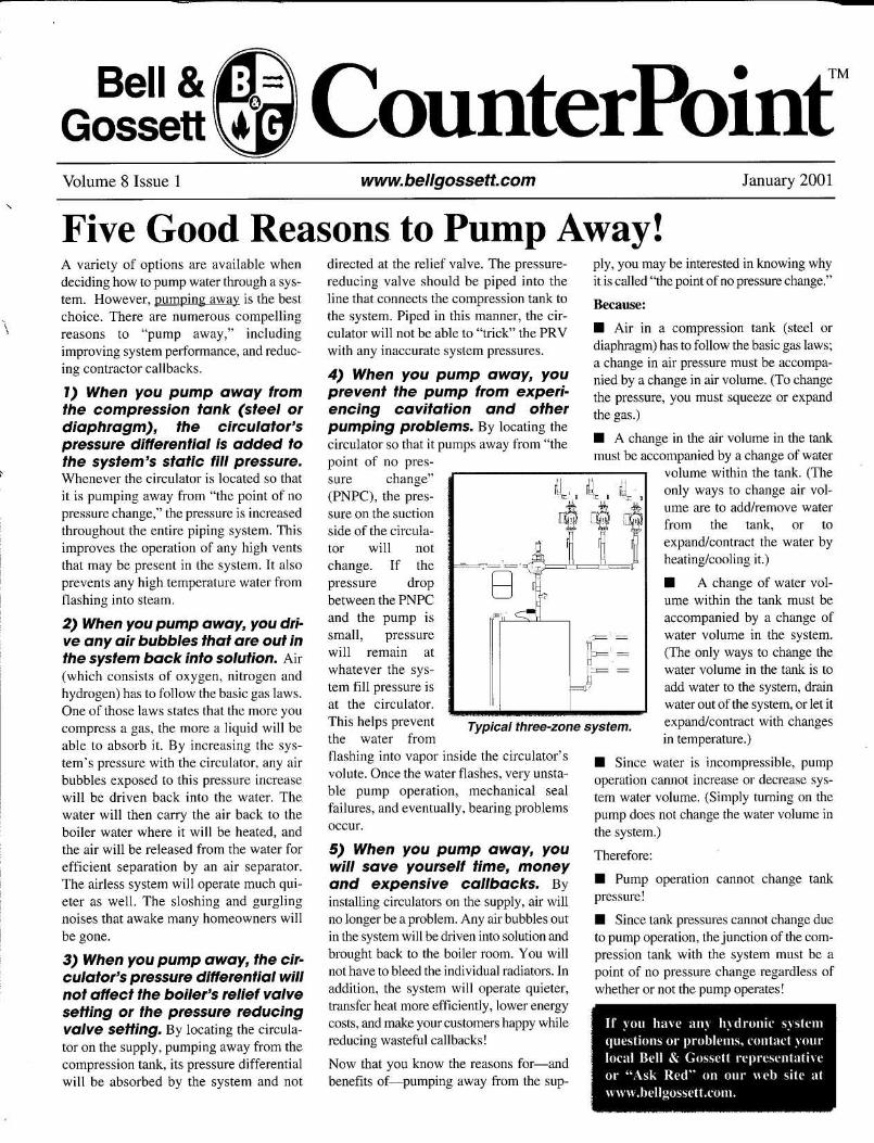
Volume 8 Issue 1
ounterPoint"www bellgossetLcom
Five Good Reasons to Pump Away!A variety of options are available whendeciding how to pump water through a sys-tem. However, pumping away is the bestchoice. There are numerous compellingreasons to "pump away," includingimproving system performance, and reduc-ing contractor callbacks .
1) When you pump away fromthe compression tank (steel ordiaphragm), the circulator'spressure differential is added tothe system's static fill pressure.Whenever the circulator is located so thatit is pumping away from "the point of nopressure change," the pressure is increasedthroughout the entire piping system . Thisimproves the operation of any high ventsthat may be present in the system . It alsoprevents any high temperature water fromflashing into steam .
2) When you pump away, you dri-ve any air bubbles that are out inthe system back into solution . Air(which consists of oxygen, nitrogen andhydrogen) has to follow the basic gas laws .One of those laws states that the more youcompress a gas, the more a liquid will beable to absorb it. By increasing the sys-tem's pressure with the circulator, any airbubbles exposed to this pressure increasewill be driven back into the water . Thewater will then carry the air back to theboiler water where it will be heated, andthe air will be released from the water forefficient separation by an air separator .The airless system will operate much qui-eter as well. The sloshing and gurglingnoises that awake many homeowners willbe gone.
3) When you pump away, the cir-culator's pressure differential willnot affect the boiler's relief valvesetting or the pressure reducingvalve setting. By locating the circula-tor on the supply, pumping away from thecompression tank, its pressure differentialwill be absorbed by the system and not
directed at the relief valve . The pressure-reducing valve should be piped into theline that connects the compression tank tothe system . Piped in this manner, the cir-culator will not be able to "trick" the PRVwith any inaccurate system pressures .
4) When you pump away, youprevent the pump from experi-encing cavitation and otherpumping problems. By locating thecirculator so that it pumps away from "thepoint of no pres-sure change"(PNPC), the pres-sure on the suctionside of the circula-tor will notchange . If thepressure dropbetween the PNPCand the pump issmall, pressurewill remain atwhatever the sys-tem fill pressure isat the circulator .This helps preventthe water fromflashing into vapor inside the circulator'svolute. Once the water flashes, very unsta-ble pump operation, mechanical sealfailures, and eventually, bearing problemsoccur .
5) When you pump away, youwill save yourself time, moneyand expensive callbacks. Byinstalling circulators on the supply, air willno longer be a problem . Any air bubbles outin the system will be driven into solution andbrought back to the boiler room . You willnot have to bleed the individual radiators . Inaddition, the system will operate quieter,transfer heat more efficiently, lower energycosts, and make your customers happy whilereducing wasteful callbacks!
Now that you know the reasons for-andbenefits of-pumping away from the sup-
I
ply, you may be interested in knowing whyit is called "the point of no pressure change ."
Because :
∎ Air in a compression tank (steel ordiaphragm) has to follow the basic gas laws ;a change in air pressure must be accompa-nied by a change in air volume. (To changethe pressure, you must squeeze or expandthe gas.)
• A change in the air volume in the tankmust be accompanied by a change of water
volume within the tank. (Theonly ways to change air vol-ume are to add/remove waterfrom the tank, or toexpand/contract the water byheating/cooling it .)
• A change of water vol-ume within the tank must beaccompanied by a change ofwater volume in the system .(The only ways to change thewater volume in the tank is toadd water to the system, drainwater out of the system, or let itexpand/contract with changesin temperature .)
• Since water is incompressible, pumpoperation cannot increase or decrease sys-tem water volume . (Simply turning on thepump does not change the water volume inthe system .)
Therefore :
•
Pump operation cannot change tankpressure!
• Since tank pressures cannot change dueto pump operation, the junction of the com-pression tank with the system must be apoint of no pressure change regardless ofwhether or not the pump operates!
If you have any hydronic systemquestions or problems, contact yourlocal Bell & Gossett representativeor "Ask Red" on our web site atwww.bellgossett .com.
t
Typical three-zone system .
0
January 2001

Bell &GossettVolume 9 Issue 1
CounterPointTM
www.bellgossett.com
Dealing with “Ghost Flows” Can be ScaryA “ghost flow” delivers heatto a terminal unit when thereisn’t supposed to be any flowat all – even when the roomthermostat is satisfied . Tolearn why this happens, readon .
Ghost flows can occur in ahydronic heating system whena pressure differential existsacross an open circuit, allow-ing water to flow where itdoesn’t belong . Here’s anexample of a complaint aboutoverheating:
A heating contractor hadreplaced a boiler over thesummer for a new customer .The contractor did not spend alot of time looking at the entirepiping system – he saw justthe piping in the boiler room .He pulled out the old boiler, installed thenew one and attached the existing piping inthe same manner as it had been piped orig-inally .
When the heating season came, the home-owner called to complain that severalzones were overheating . The heating con-tractor sent one of his service techniciansover to the house. He checked to make surethe flow-control valves were working. Hemade sure that each thermostat was wiredproperly to its respective relay and circu-lator. Everything appeared to be in goodworking order . Next, the technician wentupstairs and checked the room tempera-tures compared to the thermostat settingsof the zones that were overheating . Hefound that each overheating room’s ther-mostat was set at 60 °F, but the roomtemperature was actually 75-76 °F. At thispoint, the service technician called in thelocal Bell & Gossett Representative tolook at the job . After several questions anddiscussions, the homeowner admitted that“maybe” the same problem had existedwith the old boiler. He explained that when
BOILER
ON
OFF
B
the new boiler was installed, he assumedthat he was getting a new heating system!
A clue in the crawl spaceHere is a sketch of what the B&GRepresentative found when heinspected the basementlooking for clues :
The system had eightheating zones, each withits own circulator. Severalof these zones split into small-er, sub-circuits, and each returnfrom these sub-circuits connectedinto the common returnmanifold . What was inter-esting about thisparticular system - and what made it moredifficult to troubleshoot – was that themain return manifold that picked up allthe sub-circuit returns was in the crawlspace between the first floor ceiling andthe second floor . All you could see in theboiler room was the supply manifold withall the zone pumps and flow-controlvalves, their individual take-offs, and thereturn main that came down through the
Hydrotrol™ Flow Control Valve
June 2002
ceiling and back to the boil-er. Looking at the sketch,you can see that when onezone is calling for heat, thewater that enters the returnmain manifold has access toflow in the return of an offzone .
Note the two returns (A andB) from one of the overheat-ing zones . When the waterflows along the return mainand reaches point A, it asksitself, “which way do I go”?The answer depends uponthe difference in pressurebetween points A & B .Because there is a differencein pressure between thesetwo points, some water has toflow up the return, movingbackwards through the off
zone and back down to point B . This iswhat caused the overheating to occur . The
off-zones constantly had somewater flowing through the base-boards even though the thermostatwas satisfied .
The solution is to combine all thereturns from each zonepump together beforeentering the return main .But in this case, with allthe piping concealed inthe first floor ceiling, it
was necessary to installsmall spring flow controlvalves (Hydrotrol™) on
the returns of each baseboard circuit .After this was done, the ghost flows dis-appeared .
Remember, if you have anyhydronic questions or problems,who ya gonna call? Your local Bell& Gossett Ghostbuster. They havesolutions to all of your hot waterheating problems.

We’ve all heard the expressions, “Watertakes the path of least resistance”,and,“Water is lazy, it goes where itwants”. And if you’ve been in the heatingbusiness for any length of time, you’veprobably experiencedthese expressions in thefield when you go out ona “No Heat” call.
On such calls, you findthat the thermostat iscalling for heat, and thecirculator is running, butthere is no heat comingout of certain radiators orpieces of baseboard. Youcheck for air in the sys-tem, but only watercomes out of the vent soyou know it cannot be anair problem. Why, then,do we keep bleeding theradiation when the real problem is thatthere is not enoughwater flowing intothe radiation? If there isn’t enough pres-sure differential (delta P) across theradiation circuit, the water “short cir-cuits” through the closer circuits orzones.
In Figure 1, note the boiler, circulator andfour circuits. The numbers on the pipingcircuit represent the pressure that the cir-culator can develop at each point. In thisexample, the circulator can develop tenfeet of pressure differential. Note that asthe water moves throughout the piping,the pressure is lowered until it reachesthe suction side of the circulator where itequals zero. Also, note that as the watermoves farther away from the circulator,the pressure differential across each cir-cuit becomes less and less. And since adifference in pressure is what causes flowto occur, you can see why the farthest cir-cuit or zone might create a “No Heat”call on a very cold day. There is a differ-ence in pressure across the farthest circuitwhich means that water is flowing there.The problem is that not enoughflow is
moving through that circuit. On a coldday, all of the Btu’s will “jump off” thebaseboard in the first couple of feet, leav-ing cool water to flow through the rest ofthe circuit.
Why does it “short circuit”?Look at Figure 1 again andnotice the pressure differen-tial for the first zone. It has10’ of head pressure on thesupply and 3’ on the returnside of the zone. That meansthere is a pressure differen-tial of 7’, and this 7’differential will cause a cer-tain amount of flow to takeplace in that zone. Now lookat the farthestzone whichhas 7’ of headpressure on thesupply and 6’
on the return side, so only1’ of pressure differentialexists across this zone.
A difference in pressure iswhat causes water to flowin a closed-loop system. Ifthere is no pressure differ-ential, the fluid simplycan’t move. For water to
flow, there must be a difference in pres-sure between the inlet and outlet of a coil,a radiator, or a piece of baseboard. And– everything being equal - the greater thepressure differential, the greater the flowrate .
So how do we solve this imbalance prob-lem? In the design stage, it can bebeneficial to install reverse-return sys-tems (see Figure 2). With these types ofsystems, when the radiation is the samethroughout, the reverse-return pipingprovides equal pressure drop throughoutthe entire piping system. This equal pres-sure drop ensures adequate flow to all theradiation units. Of course, there is a bitmore piping involved, but the lack of ser-
vice calls will make it wellworth installing.
If you come across anexisting system that isexperiencing the problemsdescribed here, you shouldinstall Bell & Gossett Cir-cuit Setter balancingvalves on the return side ofeach circuit. By setting theCircuit Setters to theappropriate setting, thepressure drop in each cir-cuit will be the same. With
equal pressure drops in each circuit,there is no “path of least resistance”, andso there will be adequate flow in eachcircuit.
Whenever you find yourself trou-bleshooting a hydronic system, considerpressure differential and the role it playsin a successful heating system. Andremember, high pressure alwaysgoes tolow pressure.
Volume 9 Issue 2 www.bellgossett.com November 2002
CounterPointTMBell & Gossett
The importance of pressure differential in a hydronic system
Circuit Setter® calibrated valve balances hydronic system flow rates.
Figure 1Pressure differentials.
Figure 2Reverse-return system.
If you have any hydronic ques-tions or problems, contact yourlocal Bell & Gossett representa-tive. They have solutions to all ofyour hot water heating problems.
7’
8’
9’
10’
6’
5’
4’
3’
2’
1’
Circuit 4
Circuit 3
Circuit 2
Circuit 1
0’
4’
6’
8’
10’
3’
5’
7’
9’
1’
2’
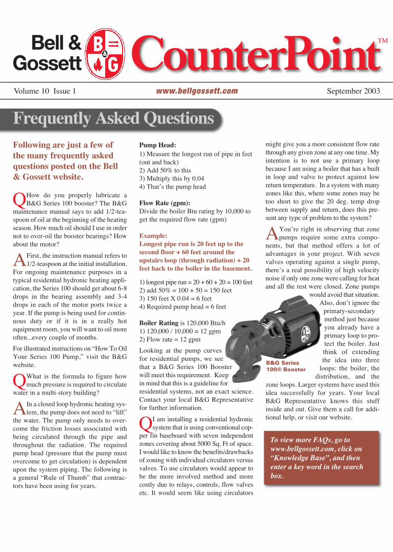
Following are just a few ofthe many frequently askedquestions posted on the Bell& Gossett website.
QHow do you properly lubricate aB&G Series 100 booster? The B&G
maintenance manual says to add 1/2-tea-spoon of oil at the beginning of the heatingseason. How much oil should I use in ordernot to over-oil the booster bearings? Howabout the motor?
AFirst, the instruction manual refers to1/2-teaspoon at the initial installation.
For ongoing maintenance purposes in atypical residential hydronic heating appli-cation, the Series 100 should get about 6-8drops in the bearing assembly and 3-4drops in each of the motor ports twice ayear. If the pump is being used for contin-uous duty or if it is in a really hotequipment room, you will want to oil moreoften...every couple of months.
For illustrated instructions on “How To OilYour Series 100 Pump,” visit the B&Gwebsite.
QWhat is the formula to figure howmuch pressure is required to circulate
water in a multi-story building?
AIn a closed loop hydronic heating sys-tem, the pump does not need to “lift”
the water. The pump only needs to over-come the friction losses associated withbeing circulated through the pipe andthroughout the radiation. The requiredpump head (pressure that the pump mustovercome to get circulation) is dependentupon the system piping. The following isa general “Rule of Thumb” that contrac-tors have been using for years.
Pump Head:1) Measure the longest run of pipe in feet(out and back)2) Add 50% to this 3) Multiply this by 0.044) That’s the pump head
Flow Rate (gpm):Divide the boiler Btu rating by 10,000 toget the required flow rate (gpm)
Example:Longest pipe run is 20 feet up to thesecond floor + 60 feet around theupstairs loop (through radiation) + 20feet back to the boiler in the basement.
1) longest pipe run = 20 + 60 + 20 = 100 feet2) add 50% = 100 + 50 = 150 feet3) 150 feet X 0.04 = 6 feet4) Required pump head = 6 feet
Boiler Rating is 120,000 Btu/h1) 120,000 / 10,000 = 12 gpm2) Flow rate = 12 gpm
Looking at the pump curvesfor residential pumps, we seethat a B&G Series 100 Boosterwill meet this requirement. Keepin mind that this is a guideline forresidential systems, not an exact science.Contact your local B&G Representativefor further information.
QI am installing a residential hydronicsystem that is using conventional cop-
per fin baseboard with seven independentzones covering about 5000 Sq. Ft of space.I would like to know the benefits/drawbacksof zoning with individual circulators versusvalves. To use circulators would appear tobe the more involved method and morecostly due to relays, controls, flow valvesetc. It would seem like using circulators
might give you a more consistent flow ratethrough any given zone at any one time. Myintention is to not use a primary loopbecause I am using a boiler that has a builtin loop and valve to protect against lowreturn temperature. In a system with manyzones like this, where some zones may betoo short to give the 20 deg. temp dropbetween supply and return, does this pre-sent any type of problem to the system?
AYou’re right in observing that zonepumps require some extra compo-
nents, but that method offers a lot ofadvantages in your project. With sevenvalves operating against a single pump,there’s a real possibility of high velocitynoise if only one zone were calling for heatand all the rest were closed. Zone pumps
would avoid that situation.Also, don’t ignore the
primary-secondarymethod just becauseyou already have aprimary loop to pro-tect the boiler. Justthink of extendingthe idea into three
loops: the boiler, thedistribution, and the
zone loops. Larger systems have used thisidea successfully for years. Your localB&G Representative knows this stuffinside and out. Give them a call for addi-tional help, or visit our website.
To view more FAQs, go towww.bellgossett.com, click on“Knowledge Base”, and thenenter a key word in the searchbox.
Volume 10 Issue 1 www.bellgossett.com September 2003
CounterPointTM
Frequently Asked Questions
B&G Series100® Booster
Bell & Gossett


A true story...At first, the call sounded like one we hearall the time - not enough heat in a roomthat had been added onto a house. Theservice guy told me the radiators were bigenough, and that the house had an oldgravity hot water system. He asked if I’dstop by to look at it, and I said I would.
When I arrived, the service guy met me inthe driveway. He immediately begantelling me all about the problem. Heexplained that someone else had installeda circulator, but that it hadn’t helpedmuch with the lack-of-heat problem. Isuggested we start in the basement and weheaded for the stairs.
The first thing I checked was the piping. Iknow that pipes have to be large enoughto carry the heat from the boiler to theradiators. That’s something a lot of guysoverlook when they’re faced with a prob-lem. Here, however, the piping lookedfine. The new fitter had taken great painsto mimic the original fitter’s piping tech-niques. The branch line to the new addi-tion took off from the main at the correctangle. It was the same as the branches thatfed the other first-floor radiators. The sizewas right, and everything else in the base-ment looked okay.
I talked to the home owner, and she toldme most of the house heated well. “It’sjust the addition,” she said. “We’ve beencold for the past two years. We need someanswers, and we need them fast!”
I asked her if the radiators in the additiongot warm and she said they did, but theroom was still uncomfortably cold. I start-ed to suspect there might not be enoughradiation in the new addition.
“What’s the heat loss in the addition?” Iasked the service guy.
“Seventeen-thousand BTUs,” he said.
I checked out the two new radiators.
Together, they put out 90 square feetEDR. I divided the heat loss of the new
addition (17,000 BTU/hr) by the squarefoot EDR. Those radiators would have tohave 190 degrees flowing through thembefore they’d heat that space. And sincemost hydronic systems work with a 20-degree temperature difference from sup-ply to return, the boiler would have to runup to 200 degrees to satisfy the load.
This is a fine point many installers over-look. They think a square foot of radiationputs out 240 BTUs, but that’s only truewhen there’s steam in the radiator. Theoutput changes when you circulate hotwater. You can see this on the chart.
So how much radiation did we need toadd to the addition? Well, a lot dependedon the average water temperature flowingthrough the rest of the house. The homeowner told me the rest of the house wascomfortable, so we ran a heat loss calcu-lation on the living room and came upwith 21,000 BTU/hr. The installed radia-tion in the living room was 175 squarefeet EDR. Again, I divided the heat lossby the installed EDR and came up with120 (21,000 ÷ 175 = 120). That meant theradiators in the living room were provid-ing comfort by putting out 120 BTU/hr.per square foot.
Looking at the chart, I could see this cor-responded with an average water temper-ature of 155 degrees. No wonder they did-
n’t have enough heat in the new addition!The water wasn’t hot enough. The origi-nal installer had designed this system torun on relatively low-temperature water(165 degrees) because he was using acoal-fired boiler. Low temperature waterwas the norm in the days of gravity hotwater heat.
If we raised the boiler water temperatureto satisfy the addition, we would havemade the rest of the house uncomfortablywarm. We also would have increased thehome owner’s fuel bills. That’s why wedecided to add an additional 52 squarefeet EDR to the addition.
We figured this out by dividing the heatloss of the addition by the heat outputwe’d expect to get from 155 degree aver-age water temperature (17,000 BTU/hr.heat loss ÷ 120 BTU/hr/square foot = 142square feet EDR required). We alreadyhad 90 square feet installed; the addition-al 52 would bring us up to 142 square feetEDR, and that’s exactly what we neededto bring the addition in line with the restof the house.
Once we had this figured out, we suggest-ed to the home owner that she put the newaddition on its own zone. We explainedhow this would give control over the sys-tem and take her from the 1920s into the21st century in a hurry. She liked the ideaand gave us the go ahead.
I sized a B&G Series 100 for each zone.The 100 provides the large flow/low headcharacteristic you need for a gravity con-version job. I added two B&G Flo-Control valves, one for each circulator, toprevent gravity circulation to a heat satis-fied zone. I also had the installer pipe in abypass to protect the boiler from thermalshock.
The system works beautifully now!
Volume 12 Issue 1 www.bellgossett.com January 2005
CounterPointTM
How A Good Troubleshooter Got Results
Bell & Gossett
For answers to your hydronicquestions, contact your local Bell& Gossett representative.
®
Average Temperature
150º F155º F160º F165º F170º F175º F180º F185º F190º F195º F200º F205º F210º F215º F
Heat Output per SquareFoot EDR
110 BTU/hr.120 BTU/hr.130 BTU/hr.140 BTU/hr.150 BTU/hr.160 BTU/hr.170 BTU/hr.180 BTU/hr.190 BTU/hr.200 BTU/hr.210 BTU/hr.220 BTU/hr.230 BTU/hr.240 BTU/hr
Radiator Heat Output Varies WithAverage Water Temperature

Have you ever wondered if the pipe youare using in that hydronic heating systemis the right size for a specific flow rate orhow you calculate the GPM for that heatloss? You can use math formulas thatwere established years ago, or look upcharts relating to flow rate in gallons perminute and pressure drop based upon pipesizes... or you can use Bell & Gossett’sSystem Syzer calculator.
The System Syzer was developed by Bell& Gossett to provide an easier way to getthe information needed to design or trou-bleshoot hot water heating systems. Thetwo-sided wheel (shown at right) is madeof durable plastic and features five scales:
Scale #1 shows the relationship amongflow rate in GPM, BTU load and tem-perature difference. If you know twoof the three, the wheel can give youthe third instantly. For example, ifyou know the BTU load and thedesired temperature drop, by look-ing at the small window on Scale#1, the necessary flow rate in GPMis shown. Scale #1 is very usefulbecause it helps you establish GPM(the required flow rate) easily.
Scale #2 is used to select the proper sizepipe to handle your GPM flow rate. Thescale lists two types of pipe: type L cop-per and schedule 40 iron in sizes from3/8” to 3”, and gives the friction loss infeet of head per 100’ as well as inmillinches. Scale #2 can also be veryhelpful when you are in a boiler room try-ing to select a new pump. If the tags fromthe boiler and original pump are missing,you can use the existing main hot waterpipe as a guide. Based on its size, look onScale #2 and determine the maximum orminimum flow that that particular pipecan handle.
Scale #3 confirms the proper pipe selec-tion from scale #2 by checking the veloc-ity of the water. Though subtle, there is adifference between friction loss in head
energy versus the velocity in feet per sec-ond of the water moving through a givenpipe size. Scale #3 makes sure that thepipe you select will not be noisy due tothe water moving too fast. The last thinga homeowner wants to hear when thethermostat calls for heat is a whistlingnoise as the water screams through thebaseboard piping. When you select a cer-tain size pipe to handle the GPM, alwaysglance down at Scale #3 to be sure it fallswithin industry standards.
Scale #4 tells you the total pressure drop
for a particular loop, zone or even thetotal system. From Scale #2, you select-ed a certain size pipe and the scale listedout the unit pressure drop per 100’ of pip-ing. When using Scale #4, you plug in thisunit pressure drop per 100’ figure againstthe total length of piping and read thetotal pressure drop. This is helpful infor-mation when selecting a circulator.
Scale #5 is the most useful scale becauseit is based on the fact that the head loss ina hydronic system will vary approximate-ly as the square of the change in flow rate.
Scale #5:
■ Determines unknown pressure drops.
■ Establishes system curves.
■ Selects control valves based upon theirCv ratings.
Sometimes circulators are purchasedbased on the “inventory method”, that is,whatever is available! When this happens,the circulator may be a little too large or alittle too small. By using Scale #5, youcan build a system curve right on thepump curve, determining exactly wherethe circulator will operate. Obviously ifthe circulator is too large, it will be pump-ing more GPM than required which mightbe acceptable as long as the increasedflow rate does not exceed the pipe’s max-
imum velocity. If the circulator is toosmall, it will be pumping fewer GPMthan required, but this isn’t necessari-ly bad, as long as the increased tem-perature drop does not reduce theoutput of the radiation.
Scale #5 can be used to select controlvalves based upon their Cv ratings, a
valve coefficient that states the neces-sary amount of flow in GPM that must
flow through the valve’s seat opening tocause a 1 pound pressure drop across thevalve. For example, a residential 3/4”zone valve has a Cv rating of 3.5. Thismeans when 3.5 GPM of water passesthrough the valve, the valve will cause a 1pound pressure drop, and it will use upone pound of energy head. Another wayof expressing this: one pound of pressuredrop is equal to 2.31’ of head loss. So ifthe zone valve has a Cv rating of 3.5 andyou pump 3.5 GPM through the valve, thevalve itself will create 2.3’ of head loss.
To obtain your own System Syzercalculator, contact your Bell &Gossett Representative. An electron-ic version of System Syzer may bedownloaded from the B&G websiteat www.bellgossett.com
Volume 12 Issue 2 www.bellgossett.com October 2005
CounterPointTM
System Syzer® - The Installer’s Best Friend
Bell & Gossett
®

When we redesigned Bell & Gossett’s ESP-PLUS® tank selection programa few years ago, we sought comments from users about the program. Thefeedback came back in two camps. One group wanted a simpler programwhere the engineer could just enter the basic sizing parameters like othermanufacturers' programs. The other group wanted even more design helpthan offered in the existing ESP-PLUS program. Our solution? Offer both.
Expansion Tank Selection TipsHelpful HVAC design information from ITT Residential & Commercial Water
S U M M E R 2 0 0 7VOLUME 13 ISSUE 1
CounterPointTM
Direct Sizing MethodIf the engineer knows the tank sizing parameters, he or shecan enter them using the direct sizing method. Users whoneed more guidance in calculating the parameters canchoose one of several methods that match their systemtype. In ESP-PLUS, each system type shows a samplesystem schematic to help the user answer questions that willlead to a proper tank size.
Each of the tank sizing parameters has a help option thatguides the user. In addition to tank sizing, you can sizeany of the hydronic equipment by clicking on that item inthe schematic. ESP-PLUS gives you the ability to spec outthe entire system including the tank, pressure reducingvalve, pressure relief valve, air separator and the new tankpurge valve.
continued on other side
ITT has announced the addition of a comprehensive new CAD library to its popular Bell &Gossett ESP-PLUS online pump selection program. The program now includes 3-dimensionaldrawings and other new, important features that allow engineers to:• Download 2D and 3D files in several file formats, or directly insert into leading
CAD systems like Inventor, Pro-Engineer, Solid Works, Mechanical Desktop,
Enhancements to ESP-PLUS CAD Library
Catia and Solid Edge.• Preview the drawings through a 3D viewer.• Access a much larger number of drawings including the new VSX line of split-
case centrifugal pumps, Series 80-SC and Series 60 close-coupled in-line pumps.

Helpful HVAC design information from ITT Residential & Commercial Water
S U M M E R 2 0 0 7VOLUME 13 ISSUE 1
CounterPointTM
If the user doesn’t know the total system volume – arequired input for tank sizing – ESP-PLUS offers twomethods for estimating the total: Component andChiller Size. The component method works by enteringthe water volume for different system components.ESP-PLUS includes calculators to help. As an example,for pipe, a calculator allows you to enter the total lengthof each of the different pipe diameters.
After the user clicks on the 'Size Tanks' button, ESP-PLUS will display all the possible tank selections andshow their cost ranking. Information screens areavailable to describe the features of each of thedifferent tank types.
When sizing a new diaphragm or bladder typeexpansion tank to replace an old compression tank, usethe ESP-PLUS program to simplify the process. Justinput all of the requisite information – system size,pressure, etc., and ESP-PLUS will help make theselection. And, once you install the new tank, make sureyou properly dispose of the old compression tank.
Expansion Tank Selection Tips(continued)
Proper Disposal of Tanks
Tank installations, removals, and reinstallations should beconducted by a trained professional and in accordance with theaccompanying installation manual. When replacing a tank, airpressure must be relieved to 0 psig prior to disassembly toeliminate any safety hazards. Failure to follow these instructionsmay cause personal injury and/or property damage. Contact alocal commercial or industrial waste disposal company or ametal recycling company to properly dispose of replaced tank.
A final report is available that shows each of thecomponents for the air control system. The reportincludes the proper field settings for tank and fillvalve pressures and links to product informationand CAD drawings.
ESP-PLUS is available online atwww.bellgossett.com and also from ITT. For moreinformation please contact your ITT HVACRepresentative or visit www.bellgossett.com
Estimating System Volume
Compliments of

“How can I lower my fuel bill?” You are probablygetting used to hearing that question! Homeownerseverywhere are asking the same question, and it’s a golden opportunity for you to talk to homeownersabout their heating system. One of the easiest optionsyou can offer any customer with a hot water heatingsystem is to install a “weather responsive” control.Simply turning down the temperature of the water in the boiler - even to a minimum of 140°F - willprovide on average…10-15% fuel savings.
Consider the way we size boilers for our heatingsystems: we pick the boiler based on the designconditions for the coldest day of the year, and we are trying to keep the customers warm by maintaining70°F inside their homes while the outside temperaturemay be as low as 0°F or even colder. However, when the outdoor temperature is not at design conditions,our boilers and radiation are in effect oversized, andfor most of the heating season the heating loadconditions are 50%-60% of design conditions. So here we are…sizing, selling and installing systems that are oversized for 95% of theseason. This is where “temperature-responsive” controls provide anopportunity to sell a better job,provide more comfort and costsavings to the customer.
Outdoor reset is accomplished whenyou increase or decrease the watertemperature going out to the systemaccording to the outdoor temperature.The system incorporates an outdoorsensor to inform the control of the
Helpful HVAC design information from ITT Residential & Commercial Water
S P R I N G 2 0 0 8VOLUME 14 ISSUE 1
CounterPointTM
WHY INSTALL A “WEATHER-RESPONSIVE” CONTROL SYSTEM?
continued on back
The Bell & Gossett ZoneTrol™ II Zone Pump Controlleris a technologically advanced device that can be
outdoor temperature since this temperature has the greatest impact on the building’s heating load.When you reduce the supply water temperature, youreduce the Btu/h output of the heating terminal unit,ie, the baseboard. This is because you are changing thedifference between the air temperature surrounding the baseboard and the water temperature inside thebaseboard. By lowering the supply water temperature,you can input the right amount of heat, offsetting theheat loss of the building. A lower water temperaturewill also create a more comfortable environment forthe homeowner because the wide temperature swingsthat normally occur will be eliminated.
TYPICAL HEATING SYSTEMSA typical heating system uses a thermostat,which sends a signal to the boiler and a circulator.The circulator turns on and sends 180°F water out tothe baseboard zone, and this happens whether it is10°F or 50°F outside. Most of the time, the 180°Fwater heats up the zone quickly, and the thermostat -sensing this temperature rise - shuts off the circulator.However, the heat loss from the building has notstopped. It continues as long as the outdoortemperature is below the desired indoor temperature.Therefore, the system continues to cycle on and off,becoming too cold and then too warm.
equipped withintegrated weather -responsive controlsto optimize ahydronic heatingsystem.

S P R I N G 2 0 0 8VOLUME 14 ISSUE 1
CounterPointTM
FLUE GAS CONDENSATIONYou should be aware of flue gas condensation.If the temperature of the boiler water is allowed tooperate below the dew point of the flue gases, they will condense back into liquid, possibly corroding theboiler, its breaching and flue pipe. The boiler will alsoexperience plugged flue gas passageways between itssections. To prevent this problem from occurring,most boiler-reset controls have a minimum supplytemperature setting that is adjustable and can be set to satisfy any boiler manufacturer’s minimum watertemperature requirements.
If you have any hydronic questions, contact your localBell & Gossett Representative. They have solutions forall your hot water heating problems.
Compliments of
(continued)
THE RESET SOLUTIONWith reset, however, when you change the temperatureof the water to match the load, the circulators and/orzone valves stay on for longer periods. This keeps theradiation warm all the time instead of cycling on andoff. This more constant supply of cooler, comfortablewater also eliminates the creaking and groaning noisesusually heard in systems that cycle 180°F water into azone. Plus, the room temperature will not override dueto the excessive water temperatures. Another benefit ofresetting a hydronic system is fuel savings. By loweringthe water temperature in the boiler and piping system,the stand-by losses and stack losses are minimized.
The concept of changing the water temperature tomatch the load of the heatingsystem is very logical and hasbeen around for quite sometime. Recently however,control technology hasadvanced considerably,providing some reasonablypriced yet very effectiveresidential and commercialhydronic controls.
WHY INSTALL A “WEATHER-RESPONSIVE” CONTROL SYSTEM?
Helpful HVAC design information from ITT Residential & Commercial Water
The Bell & Gossett NRF Circulator is used in residential and light commercialheating systems. TheNRF 3-speed modelallows the pump tocover a wide range ofhydraulic capabilities.
www.bellgossett.com