gold rx/hc installation and maintenance …...20 lp, service outlet in rx section 21 hp, service...
TRANSCRIPT

GB.RXHCF.200122
Reversible heat pump GOLD RX/HCInstallation and Maintenance InstructionsSizes 011-080
The document was originally written in Swedish.
GOLD RX/HC
GB.RXHCF.200122
We reserve the right to alter specifications.2 www.swegon.com
1. Safety Instructions .................................. 31.1 Safety isolating switch/Main switch .......................31.2 Risks .....................................................................31.3 Electrical equipment ..............................................31.4 Authorisation ........................................................31.5 Decals ...................................................................3
2. Overview ................................................. 42.1 General .................................................................42.2 Basic function diagram ..........................................5
2.2.1 Size 011-030 .............................................................52.2.2 Size 035 ....................................................................62.2.1 Size 040-080 .............................................................7
3. Installation ............................................... 83.1 Legal requirements ................................................83.2 Unloading/site transport ........................................93.3 Arrangement ........................................................93.4 Basic installation principle ......................................9
3.4.1 Height adaptation/water trap installation ...................93.4.2 Splitting/Installation of air handling unit sections ......10Basic circuit diagram .........................................................10
4. Power connection ................................. 115. Commissioning / Calibration ................ 13
5.1 General ..............................................................135.2 Phase-sequence monitor .....................................135.3 Actions if incorrect phase-sequence .....................13
6. Alarms .................................................... 137 Maintenance ........................................... 14
7.1 Cleaning .............................................................147.2 Handling of refrigerant ........................................147.3 Leakage tracing interval/ Obligation to report ..................................................147.4 Service ................................................................14
8. Trouble shooting and leakage tracing . 158.1 Troubleshooting Schedule ...................................158.2 Leakage Tracing ..................................................15
9. Dimensions ............................................ 1610. General technical data ........................ 1911. Wiring diagram ................................... 1912. Declaration of Conformity .................. 19
GB.RXHCF.200122
We reserve the right to alter specifications. www.swegon.com 3
1. SAFETY INSTRUCTIONS
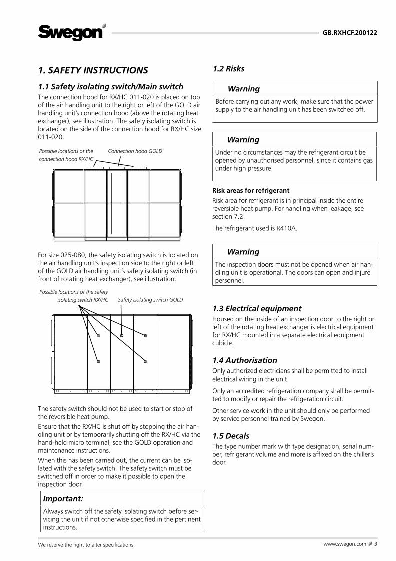
1.1 Safety isolating switch/Main switchThe connection hood for RX/HC 011-020 is placed on top of the air handling unit to the right or left of the GOLD air handling unit’s connection hood (above the rotating heat exchanger), see illustration. The safety isolating switch is located on the side of the connection hood for RX/HC size 011-020.
For size 025-080, the safety isolating switch is located on the air handling unit’s inspection side to the right or left of the GOLD air handling unit’s safety isolating switch (in front of rotating heat exchanger), see illustration.
The safety switch should not be used to start or stop of the reversible heat pump.
Ensure that the RX/HC is shut off by stopping the air han-dling unit or by temporarily shutting off the RX/HC via the hand-held micro terminal, see the GOLD operation and maintenance instructions.
When this has been carried out, the current can be iso-lated with the safety switch. The safety switch must be switched off in order to make it possible to open the inspection door.
Connection hood GOLDPossible locations of the
connection hood RX/HC
Safety isolating switch GOLD
Possible locations of the safety
isolating switch RX/HC
Important:
Always switch off the safety isolating switch before ser-vicing the unit if not otherwise specified in the pertinent instructions.
Warning
The inspection doors must not be opened when air han-dling unit is operational. The doors can open and injure personnel.
1.3 Electrical equipmentHoused on the inside of an inspection door to the right or left of the rotating heat exchanger is electrical equipment for RX/HC mounted in a separate electrical equipment cubicle.
1.4 AuthorisationOnly authorized electricians shall be permitted to install electrical wiring in the unit.
Only an accredited refrigeration company shall be permit-ted to modify or repair the refrigeration circuit.
Other service work in the unit should only be performed by service personnel trained by Swegon.
1.5 DecalsThe type number mark with type designation, serial num-ber, refrigerant volume and more is affixed on the chiller’s door.
1.2 Risks
Warning
Under no circumstances may the refrigerant circuit be opened by unauthorised personnel, since it contains gas under high pressure.
Warning
Before carrying out any work, make sure that the power supply to the air handling unit has been switched off.
Risk areas for refrigerant
Risk area for refrigerant is in principal inside the entire reversible heat pump. For handling when leakage, see section 7.2.
The refrigerant used is R410A.
GB.RXHCF.200122
We reserve the right to alter specifications.4 www.swegon.com
Refrigerant
Type R410A refrigerant is used. The refrigerant circuits are charged with refrigerant on delivery. At present, this re-frigerant has no known influence on the ozone layer and no known future restrictions are anticipated.
Refrigerant volume
See section 10. General technical data.
Installation check/Obligation to report/ Leakage tracing interval
Must be carried out according to the F-Gas Regulation EU/517/2014 and associated local legislation. See also Sec-tion 3.1.
Quality System to ISO 9001 and Environmental Management System to ISO 14001
Swegon AB works to a certified quality system that con-forms to ISO 9001 standard and a certified Environmental Management System that conforms to ISO 14001.
2. OVERVIEW
2.1 General
General
RX/HC is a complete reversible heat pump, fully inte-grated in the GOLD air handling unit.
RX/HC consists of one section with sorption rotor and one section on each side of this that contains heating/cooling engineering components.
All components from a cooling and electrical standpoint are pre-wired.
The casing is composed of cover panels and inspection doors. The outer skin is made of galvanized sheet steel, pre-painted in Swegon’s grey metallic colour (closest com-parable: RAL, 9007). The inner skin is made of aluminium-zinc plated sheet steel. Environmental Class C4. Panel thickness of 52 mm with intervening insulation consisting of mineral wool.
The evaporator and condenser consist of copper tubes and profiled aluminium fins.
RX/HC is test run prior to delivery.
RX/HC is available in 6 physical sizes, designed for GOLD air handling units in size 011-080.
RX/HC are designed and tested for ambient temperatures from -40°C to +40°C. The heat pump function withstands temperatures from -25°C to +35°C.
Compressors
The refrigerant circuit contains a variable speed controlled compressor (all sizes) that regulates the output. Size 040-080 also comprises an on/off compressor for increased capacity.
Completely direct-acting system
The RX/HC has a completely direct-acting system. It has an evaporation coil for direct-evaporating refrigerant on the cold side and a condenser coil on the hot side.

GB.RXHCF.200122
We reserve the right to alter specifications. www.swegon.com 5
03
NONC
SUC
DIS
02
SPH High pressure switch
BPH High pressure sensor
BPL Low pressure sensor
BT5X Sensor, electronic expansion valve
01 Compressor
02 Condenser (exhaust air) (Evaporator for heating operations)
03 Evaporator (supply air) (Condenser for heating operations)
06 Electronic expansion valve
07 Shut-off valve
08 Connection, service
09 Drying filter
10 Sight glass
12 4-way valve
13 Non-return valve
14 Container, fluid
19 Safety valve
20 LP, service outlet in RX section
21 HP, service outlet in RX section
22 Fluid, service outlet in RX section
01
060710 09
19
SPH
08
08 08 08
12
1313
1313
BPH
14
BT5X
For a description of the control functionality, see the function guide
reversible heat pump RX/HC.
Exhaust air coil
Supply air coil
0808
08 08
BPL20 21
22
2.2 Basic function diagram
2.2.1 Size 011-030

GB.RXHCF.200122
We reserve the right to alter specifications.6 www.swegon.com
2.2.2 Size 035
0203
NONCSUC
DIS
01
06 0710 0919
SPH
08
08 08 08
12
1313
1313
BPH
14
BT5X
Exhaust air coil
Supply air coil
0808
08
08
BPL20 21
22
SPH High pressure switch
BPH High pressure sensor
BPL Low pressure sensor
BT5X Sensor, electronic expansion valve
01 Compressor
02 Condenser (exhaust air) (Evaporator for heating operations)
03 Evaporator (supply air) (Condenser for heating operations)
06 Electronic expansion valve
07 Shut-off valve
08 Connection, service
09 Drying filter
10 Sight glass
12 4-way valve
13 Non-return valve
14 Container, fluid
19 Safety valve
20 LP, service outlet in RX section
21 HP, service outlet in RX section
22 Fluid, service outlet in RX section
23 Solenoid valve
For a description of the control functionality, see the function guide reversible heat pump RX/HC.
07 23

GB.RXHCF.200122
We reserve the right to alter specifications. www.swegon.com 7
2.2.1 Size 040-080
SPH High pressure switch
BPH High pressure sensor
BPL Low pressure sensor
BT5X Sensor, electronic expansion valve
01 Compressor
02 Condenser (exhaust air) (Evaporator for heating operations)
03 Evaporator (supply air) (Condenser for heating operations)
06 Electronic expansion valve
07 Shut-off valve
08 Connection, service
09 Drying filter
10 Sight glass
12 4-way valve
13 Non-return valve
14 Container, fluid
19 Safety valve
20 LP, service outlet in RX section
21 HP, service outlet in RX section
22 Fluid, service outlet in RX section
23 Solenoid valve
For a description of the control functionality, see the function guide reversible heat pump RX/HC.
0203
NONC
SUC
DIS
ØL
01
060710 09
19
SPH
08
08 08 08
12
1313
1313
BPH
14
BT5X
Exhaust air coil
Supply air coil
0808
08
08
BPL20 21
22
01
10
07 23

GB.RXHCF.200122
We reserve the right to alter specifications.8 www.swegon.com
3. INSTALLATION
3.1 Legal requirementsThis product relies on the fluorinated gas R410A as the refrigerant. It is known as a greenhouse gas because it contributes to the global warming if released to the atmosphere.
The European Union is committed to reducing emissions of such gases and Regulation 517/2014 (F-Gas) must be complied with.
Ensure that you are fully aware of your local regulations and that they are complied with.
The global warming potential (GWP) of greenhouse gases is expressed in equivalent mass of CO2. R410A has a GWP of 2088.
The F-Gas regulation requires that all steps are taken to eliminate the release of greenhouse gases to the atmos-phere. In accordance with Regulation 517/2014, this product is designed and manufactured so that all parts containing the refrigerant gas are made tight by weld-ing, brazing or a similar permanent connection including capped valves and capped service ports that allow proper repair or disposal and as such is hermetically sealed. The product is leak tested in the factory in accordance with (Standard).
If the installation in which this product shall be installed will have a total quantity of green house gas equivalent to 14 tonnes then it must be reported to the relevant author-ity. This is the responsibility of the operator and must be done prior to the installation.
Regulation 517/2014 requires that this product is leak tested periodically. Details are given in the table below. The product shall be leak tested after installation and prior to start-up.
Leak testing and any other service work on the refrigerant circuit must be carried out by an authorised person with the necessary training and certification in accordance with Regulation 517/2014.
Leakage warning system not installed
Table
Unit Refrigerant (kg) CO2e
GOLD RX/HC 011 6 12,53
GOLD RX/HC 012/014 8 16,7
GOLD RX/HC 020/025 10 20,88
GOLD RX/HC 030 13 27,14
GOLD RX/HC 035 18 37,58
GOLD RX/HC 040 20 41,76
GOLD RX/HC 050 17,5 36,54
GOLD RX/HC 060 20 41,76
GOLD RX/HC 070 25 52,2
GOLD RX/HC 080 30 62,64

GB.RXHCF.200122
We reserve the right to alter specifications. www.swegon.com 9
GOLD RX/HC 011-080
Right-hand version
Left-hand version
Outdoor air Supply air Extract air Exhaust air
GOLD RX/HC supply air fan, right, lower level GOLD RX/HC supply air fan, right, upper level
GOLD RX/HC supply air fan, left, upper level GOLD RX/HC supply air fan, left, lower level
3.4.1 Height adaptation/water trap installation
The drainage pipes to the evaporator/condenser must each be fitted with a water trap (accessory). The air handling unit must be raised by at least 50 mm to provide space for the water trap on the lower level. Adjustable support feet (accessory) can be appropriately fitted to the base beams for this purpose.
3.2 Unloading/site transportSee the Installation Instructions for the GOLD air handling unit.
3.3 ArrangementSee the Installation Instructions for the GOLD air handling unit.
3.4 Basic installation principle
1)
2)
3)
1) Connection hood, only size 011-020.2) Electric air heater for defrosting (accessory).3) Air recirculation section RX/HC (accessory).
1) 1)
2)
3)
1)
1)
2)
3)
1) 1)
2)
3)
1)
GB.RXHCF.200122
We reserve the right to alter specifications.10 www.swegon.com
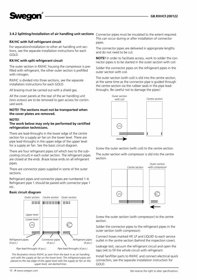
3.4.2 Splitting/Installation of air handling unit sections Connector pipes must be insulated to the extent required. This can occur during or after installation of connector pipes.
The connector pipes are delivered in appropriate lengths and do not need to be cut.
NOTE! In order to facilitate access, work to solder the con-nector pipes is to be started in the outer section with coil.
Solder the connector pipes on the refrigerant pipes in the outer section with coil.
The outer section (with coil) is slid into the centre section, at the same time as the connector pipe is guided through the centre section via the rubber seals in the pipe lead-throughs. Be careful not to damage the pipes!
Screw the outer section (with coil) to the centre section.
The outer section with compressor is slid into the centre section.
Screw the outer section (with compressor) to the centre section.
Solder the connector pipes to the refrigerant pipes in the outer section (with compressor).
Connect hoses marked HP, LP and LIQUID to each service outlet in the centre section (behind the inspection cover).
Leakage test, vacuum the refrigerant circuit and open the taps (x4) to fill the whole circuit with refrigerant.
Install fan/filter parts to RX/HC and connect electrical quick connectors, see the separate installation instruction for GOLD.
RX/HC with full refrigerant circuit
For separation/installation to other air handling unit sec-tions, see the separate installation instructions for each GOLD.
RX/HC with split refrigerant circuit
The outer section in RX/HC housing the compressor is pre-filled with refrigerant, the other outer section is prefilled with nitrogen.
RX/HC is divided into three sections, see the separate installation instructions for each GOLD.
All brazing must be carried out with a shield gas.
All the cover panels at the rear of the air handling unit (torx screws) are to be removed to gain access for contin-ued work.
NOTE! The sections must not be transported when the cover plates are removed.
NOTE! The work below may only be performed by certified refrigeration technicians.
There are lead-throughs in the lower edge of the centre section for a supply air fan on the lower level. There are pipe lead-throughs in the upper edge of the upper level for a supply air fan. See the basic circuit diagram.
There are four refrigerant pipes (of which two to the sub-cooling circuit) in each outer section. The refrigerant pipes are closed at the ends. Braze loose ends on all refrigerant pipes.
There are connector pipes supplied in some of the outer sections.
Refrigerant pipes and connector pipes are numbered 1-4. Refrigerant pipe 1 should be paired with connector pipe 1 etc.
Outer section Centre section Outer section
The illustration shows RX/HC as seen from the back in an air handling unit with the supply air fan on the lower level. The refrigerant pipes are placed on the top edge of the upper level with the supply air fan on the
upper level, see dashed lines.
-/+
Refrigerant pipes (4 pcs.)
Pipe lead-throughs (4 pcs.)
Refrigerant pipes (4 pcs.)
Pipe lead-throughs (4 pcs.)
Connector pipes (4 pcs.)
Upper level
Lower level
Basic circuit diagram -/+
Centre sectionOuter section
with compressor
Outer section with coil Centre section
Upper level
Lower level
-/+

GB.RXHCF.200122
We reserve the right to alter specifications. www.swegon.com 11
Possible locations of the
connection hood RX/HC
4. POWER CONNECTIONThe cross-sectional dimension of the power supply cable should take into consideration the ambient temperature and way the cable is run.
Cables must be routed safely. Make sure that the cables do not touch components, since surfaces could be hot or vibrate.
The connection of RX/HC is shown here. For the connec-tion of the GOLD air handling unit, see the installation instruction GOLD.
Size 011-020
Dismantle the connection hood to RX/HC.
Connect the incoming power supply to the safety switch, see the illustration.
5-core system, 400 V ±10%. Also see section 10 Technical data.
Dismantle the connec-
tion hood to RX/HC
Connect the incoming power
supply to the safety switch
Important:
Installation must be carried out by a authorised electri-cian.

GB.RXHCF.200122
We reserve the right to alter specifications.12 www.swegon.com
L1 L2 L3 N
Size 025-080
Open the inspection door in front of the electrical equip-ment cubicle.
Open the cover on the electrical equipment cubicle.
The incoming power supply is routed through the cable entry on the upper cover panel by the electrical equip-ment cubicle on the upper level and on to the safety switch block in the electric equipment cubicle.
At electrical equipment cubicle on the lower level, dismantle the cover panel above the electrical equipment cubicle. The incoming power supply is routed through the cable entry on the upper cover panel, down to the cable entries on the rear of the electrical equipment cubicle and on to the safety switch block in the electric equipment cubicle.
The cable entries on the back of the electrical equipment cubicle are accessible by opening the inspection door on the closest air handling unit section.
Possible locations of the safety
isolating switch RX/HC
Safety switch block.
Factory-fitted cables
The power supply is con-nected here
/HC
/HC/HC
/HC
Connect the incoming power supply to the safety switch block. The wiring terminal for incoming earth is situated right next to the safety switch.
5-core system, 400 V ±10%. Also see section 10 Technical data.
Inspection door in front of the electrical equipment cubicle.
Electrical equipment cubicle on the upper level Electrical equipment cubicle on the lower level
Cable entries
Safety isolating switch
Cable entries
Safety isolating switch
Cover panel (dismantled)
Inspection door in front of the electrical equipment cubicle.
GB.RXHCF.200122
We reserve the right to alter specifications. www.swegon.com 13
5. COMMISSIONING / CALIBRATION
5.1 General Commissioning is performed according to the ordinary commissioning for GOLD RX, see the separate Operation and Maintenance Instructions.
Calibration of defrosting parameters is performed at the factory before delivery.
Recalibration may be necessary in the following instances:Replacement of the GOLD air handling unit’s control card IQlogic.The exhaust air coil is modified or deformed.The exhaust air coil has a surface coating that is consid-ered small enough not to be rectified.Other suspicions of erroneous calibration.
It is important during calibration that the coil is dry and the airflow is unaffected.
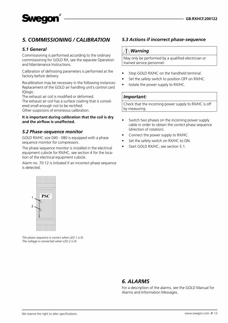
5.2 Phase-sequence monitorGOLD RX/HC size 040 - 080 is equipped with a phase sequence monitor for compressors.
The phase sequence monitor is installed in the electrical equipment cubicle for RX/HC, see section 4 for the loca-tion of the electrical equipment cubicle.
Alarm no. 70:12 is initiated if an incorrect phase sequence is detected.
1
PSC
DPA
51 3
-Ph
ase
mo
nit
ori
ng
rel
ay
1
2
The phase sequence is correct when LED 1 is lit.The voltage is connected when LED 2 is lit.
6. ALARMSFor a description of the alarms, see the GOLD Manual for Alarms and Information Messages.
5.3 Actions if incorrect phase-sequence
Warning
May only be performed by a qualified electrician or trained service personnel.
• Stop GOLD RX/HC on the handheld terminal.
• Set the safety switch to position OFF on RX/HC.
• Isolate the power supply to RX/HC.
Important:
Check that the incoming power supply to RX/HC is off by measuring.
• Switch two phases on the incoming power supply cable in order to obtain the correct phase sequence (direction of rotation).
• Connect the power supply to RX/HC.
• Set the safety switch on RX/HC to ON.
• Start GOLD RX/HC, see section 5.1.
GB.RXHCF.200122
We reserve the right to alter specifications.14 www.swegon.com
7 MAINTENANCE
7.1 CleaningIf needed, clean the inside cleaning of the unit by vacuum cleaning and wiping surfaces with a damp cloth. Inspections should be performed twice a year.
7.2 Handling of refrigerantThe refrigerant used is R410A.
The refrigerant circuit is completely charged when the unit is delivered.
Warning
Under no circumstances may the refrigerant circuit be opened by unauthorised personnel, since it contains gas under high pressure. Only an accredited refrigera-tion company shall be permitted to modify or repair the refrigeration circuit.
RX/HC is equipped with a safety valve to prevent exces-sively high pressure in the system caused by e.g. a fire.
Important:
Contact Swegon Service in the event of leakage of refrigerant.
Warning
If refrigerant is exposed to fire or in some other way becomes superheated in the atmosphere, poisonous gases can form.
7.3 Leakage tracing interval/ Obligation to reportMust be carried out according to the F-Gas Regulation EU/517/2014 and associated local legislation.
7.4 ServiceOnly service personnel trained by Swegon should be per-mitted to modify the chiller.
Important:
Filling of refrigerant must be performed in accordance with the recommendations of the refrigerant manufac-turer.
Avoid direct skin contact with refrigerant and lubricant.
Use tightly sitting protective glasses, protective gloves and covering work clothes.
Arrange ventilation/point extraction.
In the event of eye contact
rinse the eyes using an eye-wash shower (or with luke-warm water) for 20 minutes. seek a doctor.
In the event of contact with skin
carefully wash with soap and lukewarm water.
In the event of frostbite
seek a doctor.

GB.RXHCF.200122
We reserve the right to alter specifications. www.swegon.com 15
8. TROUBLE SHOOTING AND LEAK-AGE TRACING
8.1 Troubleshooting Schedule
Symptoms Possible cause ActionCompressor is not operating The voltage has been isolated.
Incorrect phase sequence.
The compressor safety circuit has been broken.
Defective compressor.
Check the operating/safety switch. Check the condi-
tion of the fuses.
Check and change the phase sequence.
Check, reset if needed.
Replace the compressor.
Too low capacity Leakage, inadequate refrigerant.
The voltage has been isolated.
No air flow or too low air flow across the evaporator.
Thermostat/Control equipment incorrectly set or defec-
tive.
Leak test, fill with refrigerant if necessary.
Check the operating/safety switch. Check the condi-
tion of the fuses.
Check the air flow.
Adjust the setting or replace faulty components.
The compressor switches off
because the low pressure sensor
has measured an excessively low
value.
Inadequate refrigerant.
No air flow or too low air flow across the evaporator.
The expansion valve is defective.
The low pressure switch is defective.
The cooling system is leaking. Tighten the leak and
charge with refrigerant.
Check the airflow.
Check, replace.
Check, replace.
The compressor switches off
because the high pressure sensor
has measured an excessively high
value.
No air flow or too low air flow across the condenser.
Excessively high exhaust air temperature.
The high pressure sensor is defective.
Check the air flow.
Check the exhaust air temperature.
Check, replace.
Significant freezing on the
evaporator.
The expansion valve is defective or incorrectly set.
No air flow or too low air flow across the evaporator.
Check. Replace or adjust setting.
Check the air flow.
8.2 Leakage TracingLeakage tracing should be carried out at least once per year as a precaution. The leakage tracing inspection must be documented.
If the system is leaking, this will become apparent firstly by impaired performance, or if the leakage is substantial, when the system does not operate at all.
If you suspect that the cooling system is leaking refriger-ant, check the level of refrigerant in the sight glass located on the heating circuit’s electrical equipment cubicle.
If you see continuous and a substantial amount of bub-bling in the sight glass and the reversible heat pump operates at appreciably lower capacity than normal, the system is probably leaking. One or several bubbles appear-ing when the chiller is started up, operation at reduced capacity or normal operation need not necessarily indicate a refrigerant deficiency.
If it is bubbling in the sight glass and the chiller operates at appreciably lower capacity, call for qualified service help.
NOTE! Maintenance work in the refrigerant system is per-mitted to be carried out only by an accredited inspectorate (a company with requisite authorisation).

GB.RXHCF.200122
We reserve the right to alter specifications.16 www.swegon.com
9. DIMENSIONS
RX/HC 011/012
45 45J
K76
5245 45J
K 76380 18
52
16
E
/HC
ø ø
350 350
= =
Size A B C D E F G H J K L Ø Weight, kg
011 647 1199 324 565 1695 324 647 1295 953 551 2989 500 737-845
012 647 1199 324 565 1695 324 647 1295 953 551 2989 500 765-879
The illustration shows RX/HC integrated in a GOLD standard air handling unit set-up. The installation length for RX/HC corresponds to the E-measurement.Placement of the air handling unit sections, duct connections, connection hood, drain pipe, etc. may vary depending on the selected variant.
* The air handling unit is supplied without end connection panel if a duct accessory housed in an insulated casing will be connected. The AHU can also be supplied with full face end connection panel (accessory).
RX/HC 014/020
EF
52
F
52
11
M
M
76
45 45J
380 18
C
/HC
Size A B C D E F G H I J K L M Weight, kg
014 757,5 1400 1695 565 205 400 1000 1551 375 1154 200 3210 188 934-1074
020 757,5 1400 1695 565 205 400 1000 1551 375 1154 200 3210 188 964-1124
The illustration shows RX/HC integrated in a GOLD standard air handling unit set-up. The installation length for RX/HC corresponds to the C-measurement.Placement of the air handling unit sections, duct connections, connection hood, drain pipe, etc. may vary depending on the selected variant.
* The air handling unit is supplied without end connection panel if a duct accessory housed in an insulated casing will be connected. The AHU can also be supplied with full face end connection panel (accessory).

GB.RXHCF.200122
We reserve the right to alter specifications. www.swegon.com 17
RX/HC 025/030
M
35
M
45 45J
C
52
E
52
/HC
Size A B C D E F G H I J K L M Weight, kg
025 848 1600 1695 565 200 500 1200 1811 405 1354 200 3391 203 1238-1445
030 848 1600 1695 565 200 500 1200 1811 405 1354 200 3391 203 1300-1479
The illustration shows RX/HC integrated in a GOLD standard air handling unit set-up. The installation length for RX/HC corresponds to the C-measurement.Placement of the air handling unit sections, duct connections, connection hood, drain pipe, etc. may vary depending on the selected variant.
* The air handling unit is supplied without end connection panel if a duct accessory housed in an insulated casing will be connected. The AHU can also be supplied with full face end connection panel (accessory).
M
M
45 45J
/HC
40
C
52 52
Size A B C D E F G H I J K L M Weight, kg
035 1038.5 1990 1695 565 245 600 1400 2159 479 1744 295 3772 240 1664-1922
040 1038.5 1990 1695 565 245 600 1400 2159 479 1744 295 3772 240 1740-2016
RX/HC 035/040
The illustration shows RX/HC integrated in a GOLD standard air handling unit set-up. The installation length for RX/HC corresponds to the C-measurement.Placement of the air handling unit sections, duct connections, connection hood, drain pipe, etc. may vary depending on the selected variant.
* The air handling unit is supplied without end connection panel if a duct accessory housed in an insulated casing will be connected. The AHU can also be supplied with full face end connection panel (accessory).
GB.RXHCF.200122
We reserve the right to alter specifications.18 www.swegon.com
M
M
40
C
52 52
78 782162
123 835 83545402J J
/HC
Size A B C D E F G H I J K L M Weight, kg
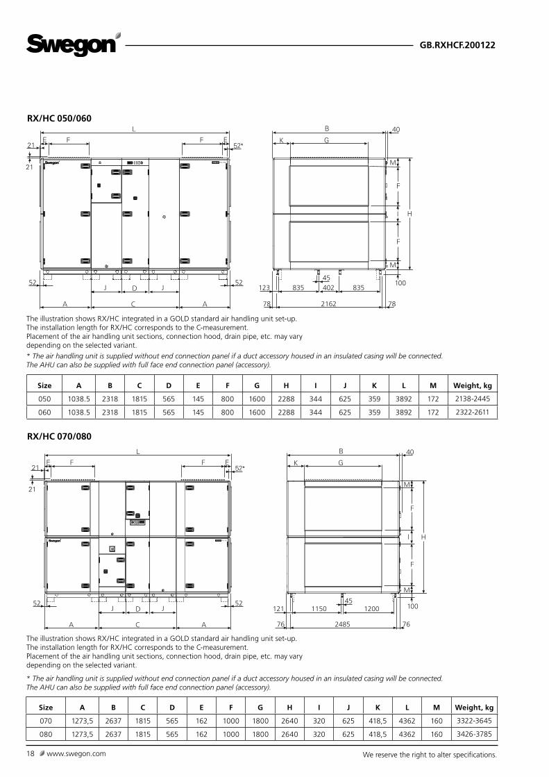
050 1038.5 2318 1815 565 145 800 1600 2288 344 625 359 3892 172 2138-2445
060 1038.5 2318 1815 565 145 800 1600 2288 344 625 359 3892 172 2322-2611
The illustration shows RX/HC integrated in a GOLD standard air handling unit set-up. The installation length for RX/HC corresponds to the C-measurement.Placement of the air handling unit sections, connection hood, drain pipe, etc. may vary depending on the selected variant.
* The air handling unit is supplied without end connection panel if a duct accessory housed in an insulated casing will be connected. The AHU can also be supplied with full face end connection panel (accessory).
RX/HC 050/060
40
M
M
C
52 52J J
76
121 1150 120045
762485
/HC
Size A B C D E F G H I J K L M Weight, kg
070 1273,5 2637 1815 565 162 1000 1800 2640 320 625 418,5 4362 160 3322-3645
080 1273,5 2637 1815 565 162 1000 1800 2640 320 625 418,5 4362 160 3426-3785
RX/HC 070/080
The illustration shows RX/HC integrated in a GOLD standard air handling unit set-up. The installation length for RX/HC corresponds to the C-measurement.Placement of the air handling unit sections, connection hood, drain pipe, etc. may vary depending on the selected variant.
* The air handling unit is supplied without end connection panel if a duct accessory housed in an insulated casing will be connected. The AHU can also be supplied with full face end connection panel (accessory).
GB.RXHCF.200122
We reserve the right to alter specifications. www.swegon.com 19
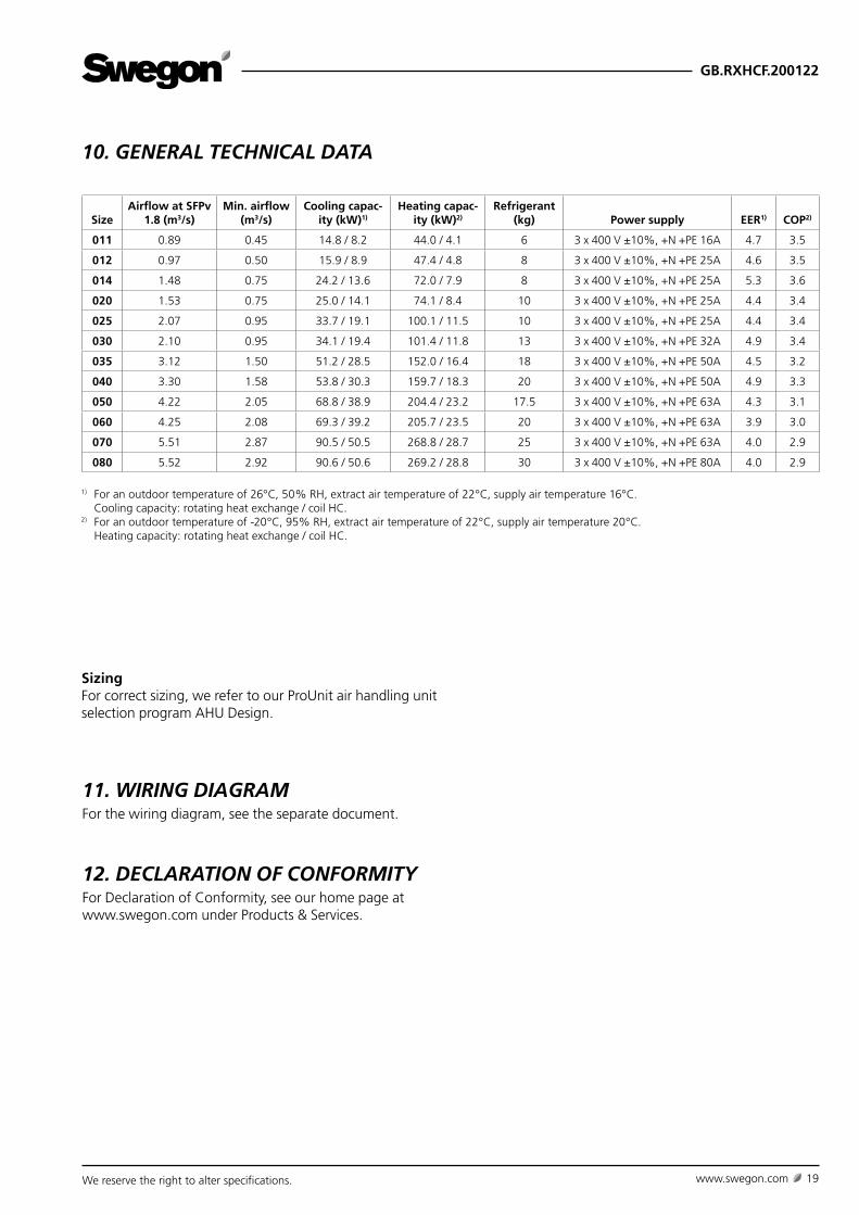
SizingFor correct sizing, we refer to our ProUnit air handling unit selection program AHU Design.
10. GENERAL TECHNICAL DATA
11. WIRING DIAGRAMFor the wiring diagram, see the separate document.
1) For an outdoor temperature of 26°C, 50% RH, extract air temperature of 22°C, supply air temperature 16°C. Cooling capacity: rotating heat exchange / coil HC.2) For an outdoor temperature of -20°C, 95% RH, extract air temperature of 22°C, supply air temperature 20°C. Heating capacity: rotating heat exchange / coil HC.
SizeAirflow at SFPv
1.8 (m3/s)Min. airflow
(m3/s)Cooling capac-
ity (kW)1)
Heating capac-ity (kW)2)
Refrigerant (kg) Power supply EER1) COP2)
011 0.89 0.45 14.8 / 8.2 44.0 / 4.1 6 3 x 400 V ±10%, +N +PE 16A 4.7 3.5
012 0.97 0.50 15.9 / 8.9 47.4 / 4.8 8 3 x 400 V ±10%, +N +PE 25A 4.6 3.5
014 1.48 0.75 24.2 / 13.6 72.0 / 7.9 8 3 x 400 V ±10%, +N +PE 25A 5.3 3.6
020 1.53 0.75 25.0 / 14.1 74.1 / 8.4 10 3 x 400 V ±10%, +N +PE 25A 4.4 3.4
025 2.07 0.95 33.7 / 19.1 100.1 / 11.5 10 3 x 400 V ±10%, +N +PE 25A 4.4 3.4
030 2.10 0.95 34.1 / 19.4 101.4 / 11.8 13 3 x 400 V ±10%, +N +PE 32A 4.9 3.4
035 3.12 1.50 51.2 / 28.5 152.0 / 16.4 18 3 x 400 V ±10%, +N +PE 50A 4.5 3.2
040 3.30 1.58 53.8 / 30.3 159.7 / 18.3 20 3 x 400 V ±10%, +N +PE 50A 4.9 3.3
050 4.22 2.05 68.8 / 38.9 204.4 / 23.2 17.5 3 x 400 V ±10%, +N +PE 63A 4.3 3.1
060 4.25 2.08 69.3 / 39.2 205.7 / 23.5 20 3 x 400 V ±10%, +N +PE 63A 3.9 3.0
070 5.51 2.87 90.5 / 50.5 268.8 / 28.7 25 3 x 400 V ±10%, +N +PE 63A 4.0 2.9
080 5.52 2.92 90.6 / 50.6 269.2 / 28.8 30 3 x 400 V ±10%, +N +PE 80A 4.0 2.9
12. DECLARATION OF CONFORMITYFor Declaration of Conformity, see our home page at www.swegon.com under Products & Services.

GB.RXHCF.200122
We reserve the right to alter specifications.20 www.swegon.com