glowing skullcandy headphones mod - adafruit industries · glowing skullcandy headphones mod...
TRANSCRIPT

Glowing Skullcandy Headphones ModCreated by Becky Stern
Last updated on 2015-02-20 01:02:25 PM EST
2349
1012151825
Guide Contents
Guide ContentsOverviewTools & SuppliesCircuit DiagramDisassemble & Prep HeadphonesMake Pixel RingsProgram & TestInstall CircuitWear 'em!
© Adafruit Industries https://learn.adafruit.com/glowing-skullcandy-headphones-mod Page 2 of 26
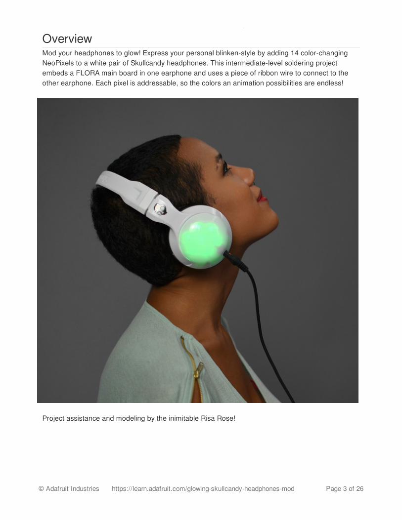
OverviewMod your headphones to glow! Express your personal blinken-style by adding 14 color-changingNeoPixels to a white pair of Skullcandy headphones. This intermediate-level soldering projectembeds a FLORA main board in one earphone and uses a piece of ribbon wire to connect to theother earphone. Each pixel is addressable, so the colors an animation possibilities are endless!
Project assistance and modeling by the inimitable Risa Rose!
© Adafruit Industries https://learn.adafruit.com/glowing-skullcandy-headphones-mod Page 3 of 26
Tools & SuppliesPrerequisite guides:
Getting Started with FLORA (http://adafru.it/aSZ)FLORA RGB smart NeoPixels (http://adafru.it/aRT)
You will need the following materials:
FLORA main board (http://adafru.it/659)14 FLORA NeoPixels (http://adafru.it/1260) or 2 NeoPixel rings (http://adafru.it/1463)Tactile on/off switch (http://adafru.it/1092)Tiny lipoly battery (http://adafru.it/1317) with charger (http://adafru.it/1304)Stranded ribbon wire (at least three conductors, this fabric ribbon 4-channelwire (http://adafru.it/1373) is good if you don't already have some regular ribbon cable in yourtoolbox)Solid-core hookup wire (http://adafru.it/290)Heat-shrink tubing (http://adafru.it/344)Clear packing tape
You will need the following tools:
Any entry level 'all-in-one' soldering iron that youmight find at your local hardware store shouldwork. As with most things in life, you get what youpay for. Upgrading to a higher end soldering iron setup, likethe Hakko FX-888 that we stock in ourstore (http://adafru.it/dyY), will make soldering funand easy.
Do not use a "ColdHeat" soldering iron! They arenot suitable for delicate electronics work and candamage the Flora (see here (http://adafru.it/aOo)).
Click here to buy our entry level adjustable 30W110V soldering iron. (http://adafru.it/180)
Click here to upgrade to a Genuine Hakko FX-888adjustable temperature solderingiron. (http://adafru.it/dyY)
Learn how to solder with tons oftutorials! (http://adafru.it/aTk)
© Adafruit Industries https://learn.adafruit.com/glowing-skullcandy-headphones-mod Page 4 of 26

You will want rosin core, 60/40 solder. Good solderis a good thing. Bad solder leads to bridging andcold solder joints which can be tough to find.
Click here to buy a spool of leaded solder(recommended for beginners). (http://adafru.it/145)
Click here to buy a spool of lead-freesolder. (http://adafru.it/734)
You will need a good quality basic multimeter that
© Adafruit Industries https://learn.adafruit.com/glowing-skullcandy-headphones-mod Page 5 of 26

can measure voltage and continuity.
Click here to buy a basicmultimeter. (http://adafru.it/71)
Click here to buy a top of the linemultimeter. (http://adafru.it/308)
Click here to buy a pocketmultimeter. (http://adafru.it/850)
Don't forget to learn how to use your multimetertoo! (http://adafru.it/aOy)
Don't forget your wirestrippers (http://adafru.it/527),pliers (http://adafru.it/146), and flushsnips (http://adafru.it/152)!
© Adafruit Industries https://learn.adafruit.com/glowing-skullcandy-headphones-mod Page 6 of 26
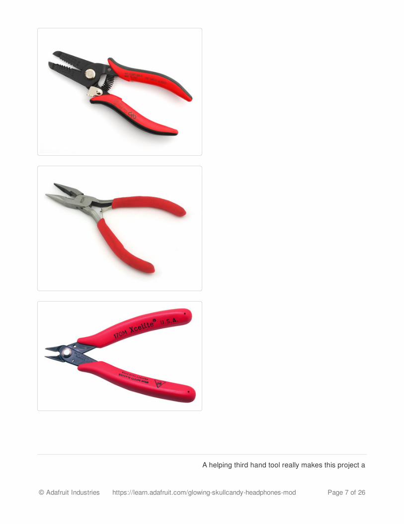
A helping third hand tool really makes this project a
© Adafruit Industries https://learn.adafruit.com/glowing-skullcandy-headphones-mod Page 7 of 26
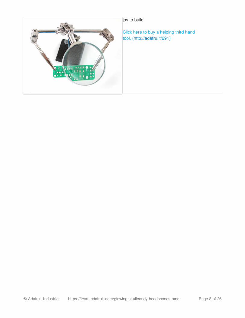
joy to build.
Click here to buy a helping third handtool. (http://adafru.it/291)
© Adafruit Industries https://learn.adafruit.com/glowing-skullcandy-headphones-mod Page 8 of 26
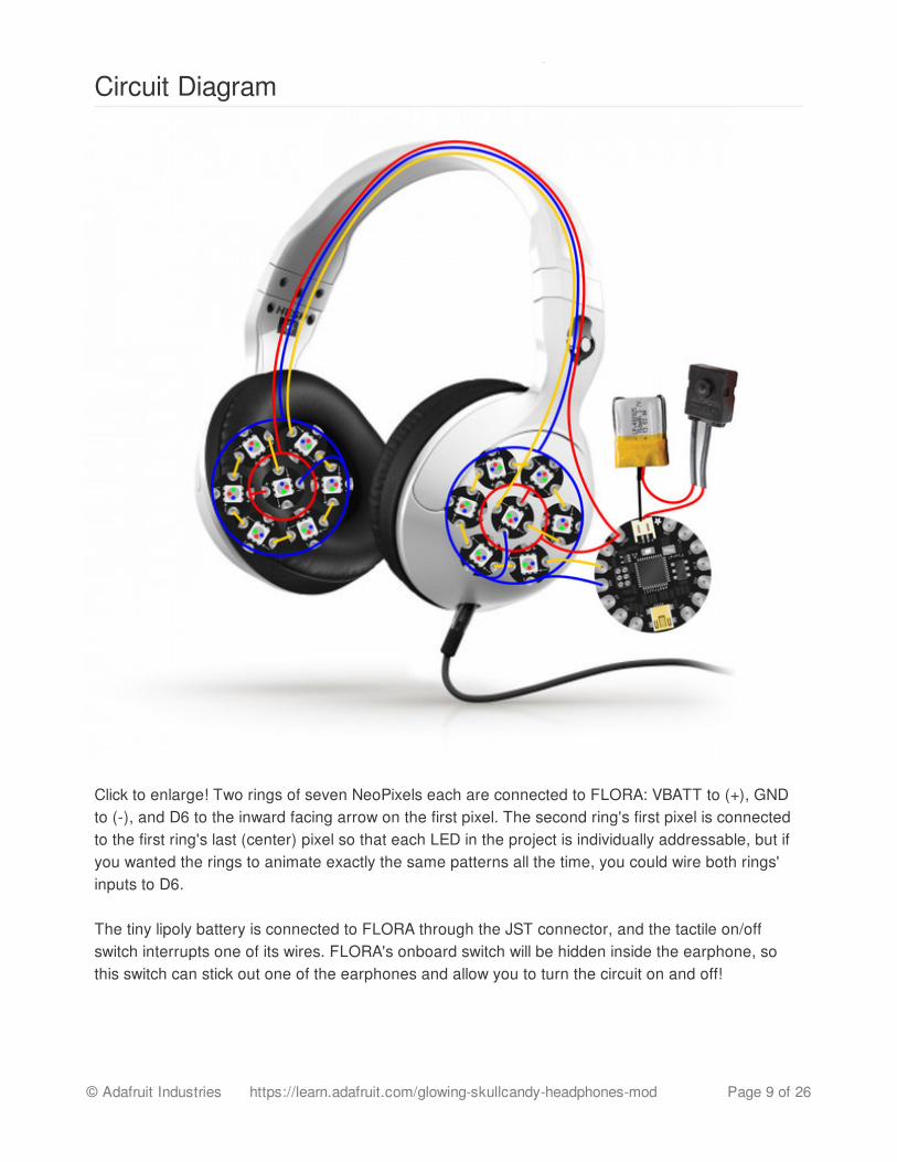
Circuit Diagram
Click to enlarge! Two rings of seven NeoPixels each are connected to FLORA: VBATT to (+), GNDto (-), and D6 to the inward facing arrow on the first pixel. The second ring's first pixel is connectedto the first ring's last (center) pixel so that each LED in the project is individually addressable, but ifyou wanted the rings to animate exactly the same patterns all the time, you could wire both rings'inputs to D6.
The tiny lipoly battery is connected to FLORA through the JST connector, and the tactile on/offswitch interrupts one of its wires. FLORA's onboard switch will be hidden inside the earphone, sothis switch can stick out one of the earphones and allow you to turn the circuit on and off!
© Adafruit Industries https://learn.adafruit.com/glowing-skullcandy-headphones-mod Page 9 of 26
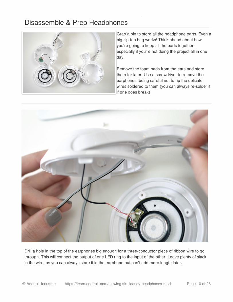
Disassemble & Prep HeadphonesGrab a bin to store all the headphone parts. Even abig zip-top bag works! Think ahead about howyou're going to keep all the parts together,especially if you're not doing the project all in oneday.
Remove the foam pads from the ears and storethem for later. Use a screwdriver to remove theearphones, being careful not to rip the delicatewires soldered to them (you can always re-solder itif one does break)
Drill a hole in the top of the earphones big enough for a three-conductor piece of ribbon wire to gothrough. This will connect the output of one LED ring to the input of the other. Leave plenty of slackin the wire, as you can always store it in the earphone but can't add more length later.
© Adafruit Industries https://learn.adafruit.com/glowing-skullcandy-headphones-mod Page 10 of 26

© Adafruit Industries https://learn.adafruit.com/glowing-skullcandy-headphones-mod Page 11 of 26
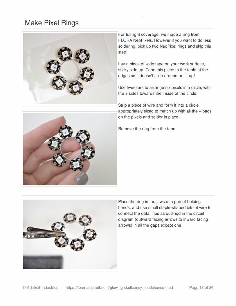
Make Pixel RingsFor full light coverage, we made a ring fromFLORA NeoPixels. However if you want to do lesssoldering, pick up two NeoPixel rings and skip thisstep!
Lay a piece of wide tape on your work surface,sticky side up. Tape this piece to the table at theedges so it doesn't slide around or lift up!
Use tweezers to arrange six pixels in a circle, withthe + sides towards the inside of the circle.
Strip a piece of wire and form it into a circleappropriately sized to match up with all the + padson the pixels and solder in place.
Remove the ring from the tape.
Place the ring in the jaws of a pair of helpinghands, and use small staple-shaped bits of wire toconnect the data lines as outlined in the circuitdiagram (outward facing arrows to inward facingarrows) in all the gaps except one.
© Adafruit Industries https://learn.adafruit.com/glowing-skullcandy-headphones-mod Page 12 of 26
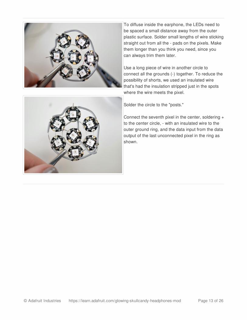
To diffuse inside the earphone, the LEDs need tobe spaced a small distance away from the outerplastic surface. Solder small lengths of wire stickingstraight out from all the - pads on the pixels. Makethem longer than you think you need, since youcan always trim them later.
Use a long piece of wire in another circle toconnect all the grounds (-) together. To reduce thepossibility of shorts, we used an insulated wirethat's had the insulation stripped just in the spotswhere the wire meets the pixel.
Solder the circle to the "posts."
Connect the seventh pixel in the center, soldering +to the center circle, - with an insulated wire to theouter ground ring, and the data input from the dataoutput of the last unconnected pixel in the ring asshown.
© Adafruit Industries https://learn.adafruit.com/glowing-skullcandy-headphones-mod Page 13 of 26
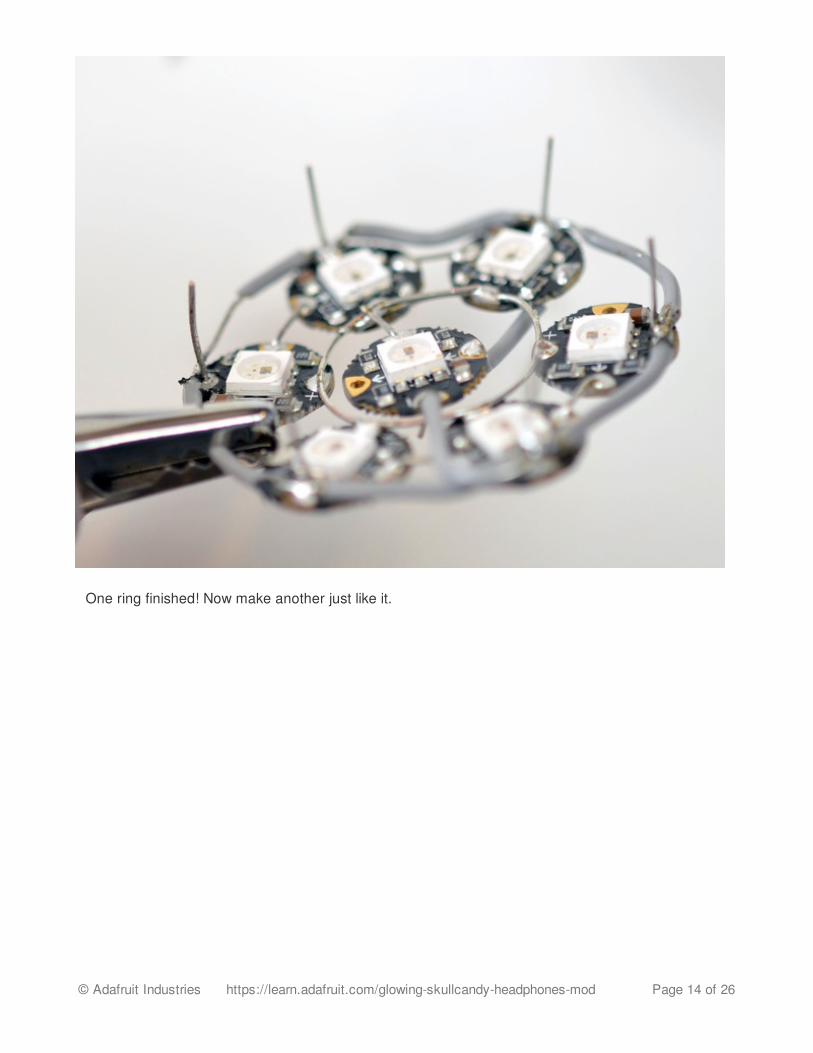
One ring finished! Now make another just like it.
© Adafruit Industries https://learn.adafruit.com/glowing-skullcandy-headphones-mod Page 14 of 26
Program & Test
© Adafruit Industries https://learn.adafruit.com/glowing-skullcandy-headphones-mod Page 15 of 26
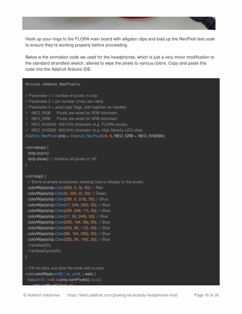
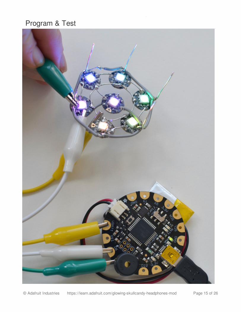
Hook up your rings to the FLORA main board with alligator clips and load up the NeoPixel test codeto ensure they're working properly before proceeding.
Below is the animation code we used for the headphones, which is just a very minor modification tothe standard strandtest sketch, altered to wipe the pixels to various colors. Copy and paste thiscode into the Adafruit Arduino IDE:
#include <Adafruit_NeoPixel.h>
// Parameter 1 = number of pixels in strip// Parameter 2 = pin number (most are valid)// Parameter 3 = pixel type flags, add together as needed:// NEO_RGB Pixels are wired for RGB bitstream// NEO_GRB Pixels are wired for GRB bitstream// NEO_KHZ400 400 KHz bitstream (e.g. FLORA pixels)// NEO_KHZ800 800 KHz bitstream (e.g. High Density LED strip)Adafruit_NeoPixel strip = Adafruit_NeoPixel(14, 6, NEO_GRB + NEO_KHZ800);
void setup() { strip.begin(); strip.show(); // Initialize all pixels to 'off'}
void loop() { // Some example procedures showing how to display to the pixels: colorWipe(strip.Color(255, 0, 0), 50); // Red colorWipe(strip.Color(0, 255, 0), 50); // Green colorWipe(strip.Color(200, 0, 218), 50); // Blue colorWipe(strip.Color(17, 249, 230), 50); // Blue colorWipe(strip.Color(235, 249, 17), 50); // Blue colorWipe(strip.Color(17, 93, 249), 50); // Blue colorWipe(strip.Color(255, 164, 56), 50); // Blue colorWipe(strip.Color(255, 56, 112), 50); // Blue colorWipe(strip.Color(56, 164, 255), 50); // Blue colorWipe(strip.Color(255, 56, 140), 50); // Blue //rainbow(20); //rainbowCycle(20);}
// Fill the dots one after the other with a colorvoid colorWipe(uint32_t c, uint8_t wait) { for(uint16_t i=0; i<strip.numPixels(); i++) { strip.setPixelColor(i, c);
© Adafruit Industries https://learn.adafruit.com/glowing-skullcandy-headphones-mod Page 16 of 26

strip.setPixelColor(i, c); strip.show(); delay(wait); }}
void rainbow(uint8_t wait) { uint16_t i, j;
for(j=0; j<256; j++) { for(i=0; i<strip.numPixels(); i++) { strip.setPixelColor(i, Wheel((i+j) & 255)); } strip.show(); delay(wait); }}
// Slightly different, this makes the rainbow equally distributed throughoutvoid rainbowCycle(uint8_t wait) { uint16_t i, j;
for(j=0; j<256*5; j++) { // 5 cycles of all colors on wheel for(i=0; i< strip.numPixels(); i++) { strip.setPixelColor(i, Wheel(((i * 256 / strip.numPixels()) + j) & 255)); } strip.show(); delay(wait); }}
// Input a value 0 to 255 to get a color value.// The colours are a transition r - g - b - back to r.uint32_t Wheel(byte WheelPos) { if(WheelPos < 85) { return strip.Color(WheelPos * 3, 255 - WheelPos * 3, 0); } else if(WheelPos < 170) { WheelPos -= 85; return strip.Color(255 - WheelPos * 3, 0, WheelPos * 3); } else { WheelPos -= 170; return strip.Color(0, WheelPos * 3, 255 - WheelPos * 3); }}
© Adafruit Industries https://learn.adafruit.com/glowing-skullcandy-headphones-mod Page 17 of 26
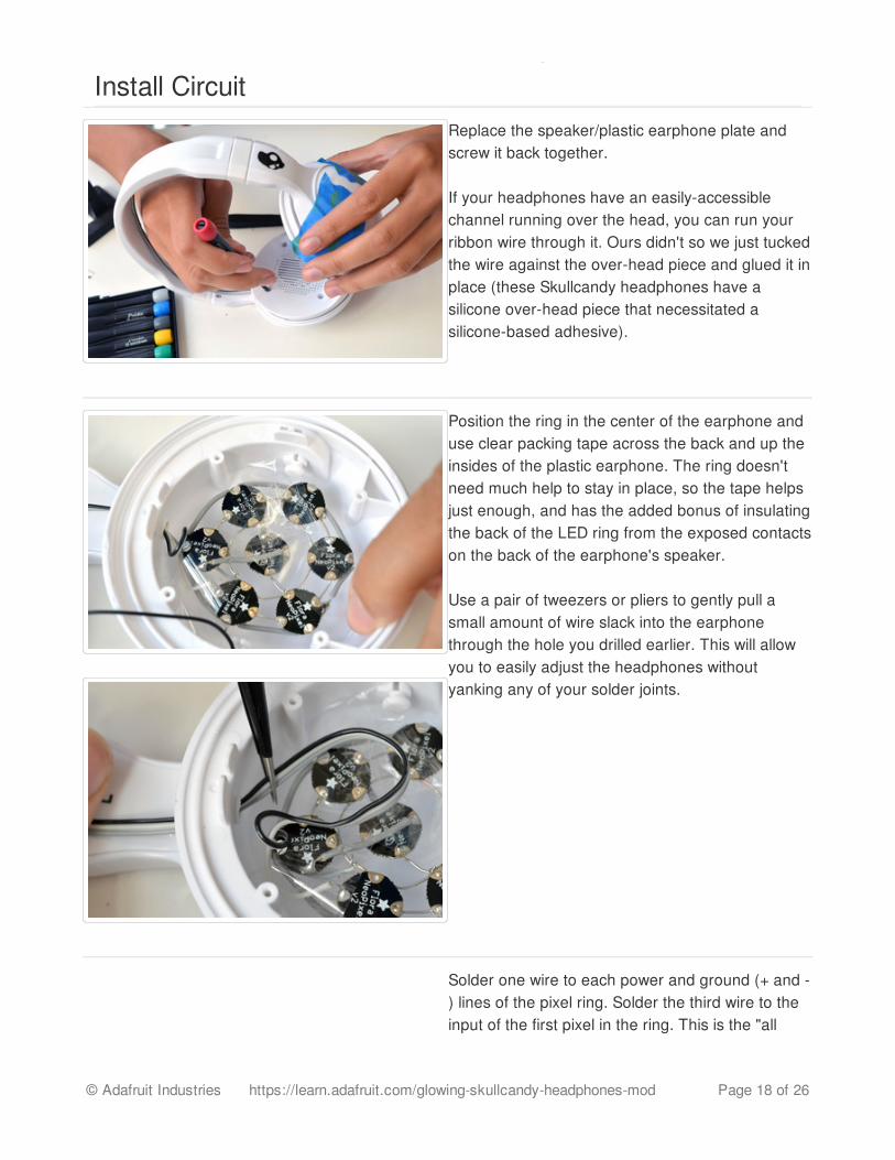
Install CircuitReplace the speaker/plastic earphone plate andscrew it back together.
If your headphones have an easily-accessiblechannel running over the head, you can run yourribbon wire through it. Ours didn't so we just tuckedthe wire against the over-head piece and glued it inplace (these Skullcandy headphones have asilicone over-head piece that necessitated asilicone-based adhesive).
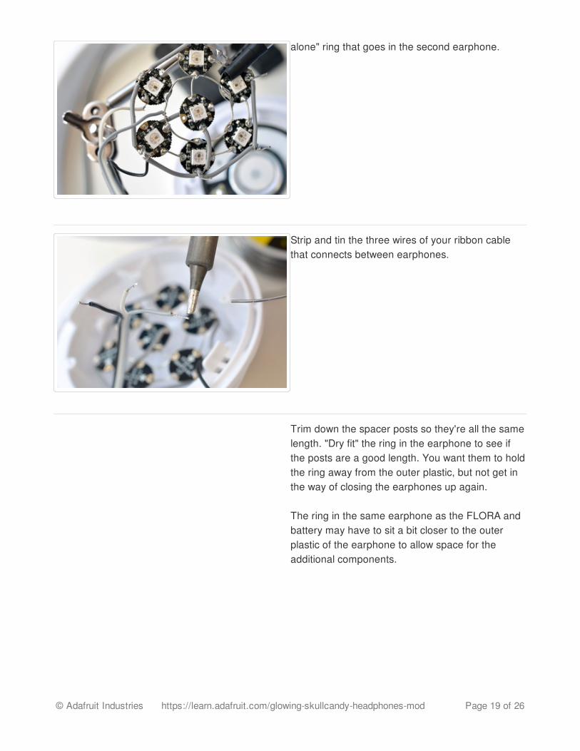
Position the ring in the center of the earphone anduse clear packing tape across the back and up theinsides of the plastic earphone. The ring doesn'tneed much help to stay in place, so the tape helpsjust enough, and has the added bonus of insulatingthe back of the LED ring from the exposed contactson the back of the earphone's speaker.
Use a pair of tweezers or pliers to gently pull asmall amount of wire slack into the earphonethrough the hole you drilled earlier. This will allowyou to easily adjust the headphones withoutyanking any of your solder joints.
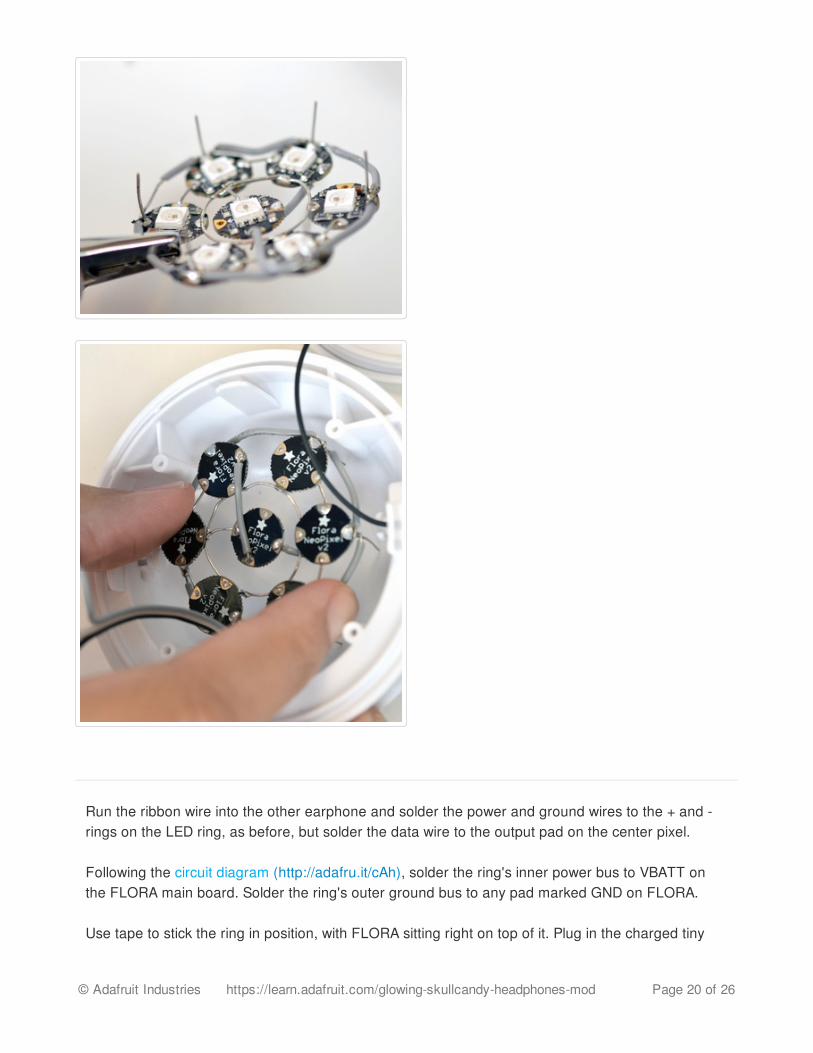
Solder one wire to each power and ground (+ and -) lines of the pixel ring. Solder the third wire to theinput of the first pixel in the ring. This is the "all
© Adafruit Industries https://learn.adafruit.com/glowing-skullcandy-headphones-mod Page 18 of 26
alone" ring that goes in the second earphone.
Strip and tin the three wires of your ribbon cablethat connects between earphones.
Trim down the spacer posts so they're all the samelength. "Dry fit" the ring in the earphone to see ifthe posts are a good length. You want them to holdthe ring away from the outer plastic, but not get inthe way of closing the earphones up again.
The ring in the same earphone as the FLORA andbattery may have to sit a bit closer to the outerplastic of the earphone to allow space for theadditional components.
© Adafruit Industries https://learn.adafruit.com/glowing-skullcandy-headphones-mod Page 19 of 26
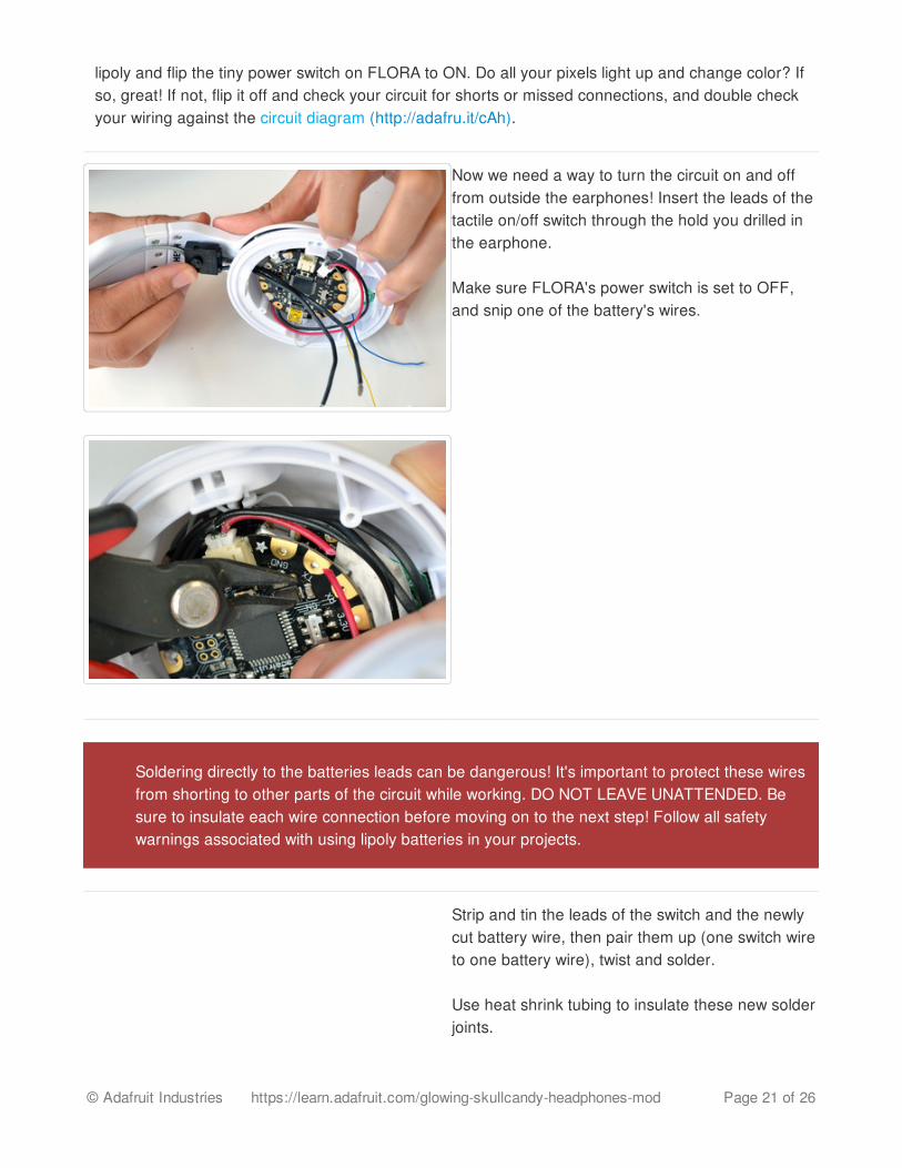
Run the ribbon wire into the other earphone and solder the power and ground wires to the + and -rings on the LED ring, as before, but solder the data wire to the output pad on the center pixel.
Following the circuit diagram (http://adafru.it/cAh), solder the ring's inner power bus to VBATT onthe FLORA main board. Solder the ring's outer ground bus to any pad marked GND on FLORA.
Use tape to stick the ring in position, with FLORA sitting right on top of it. Plug in the charged tiny
© Adafruit Industries https://learn.adafruit.com/glowing-skullcandy-headphones-mod Page 20 of 26
lipoly and flip the tiny power switch on FLORA to ON. Do all your pixels light up and change color? Ifso, great! If not, flip it off and check your circuit for shorts or missed connections, and double checkyour wiring against the circuit diagram (http://adafru.it/cAh).
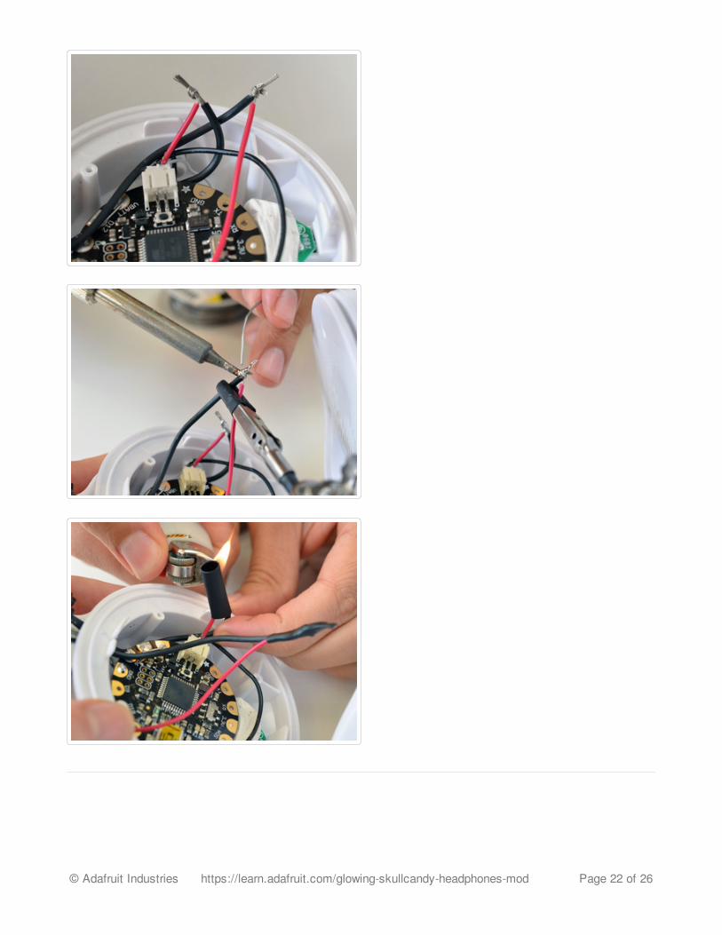
Now we need a way to turn the circuit on and offfrom outside the earphones! Insert the leads of thetactile on/off switch through the hold you drilled inthe earphone.
Make sure FLORA's power switch is set to OFF,and snip one of the battery's wires.
Strip and tin the leads of the switch and the newlycut battery wire, then pair them up (one switch wireto one battery wire), twist and solder.
Use heat shrink tubing to insulate these new solderjoints.
Soldering directly to the batteries leads can be dangerous! It's important to protect these wiresfrom shorting to other parts of the circuit while working. DO NOT LEAVE UNATTENDED. Besure to insulate each wire connection before moving on to the next step! Follow all safetywarnings associated with using lipoly batteries in your projects.
© Adafruit Industries https://learn.adafruit.com/glowing-skullcandy-headphones-mod Page 21 of 26
© Adafruit Industries https://learn.adafruit.com/glowing-skullcandy-headphones-mod Page 22 of 26
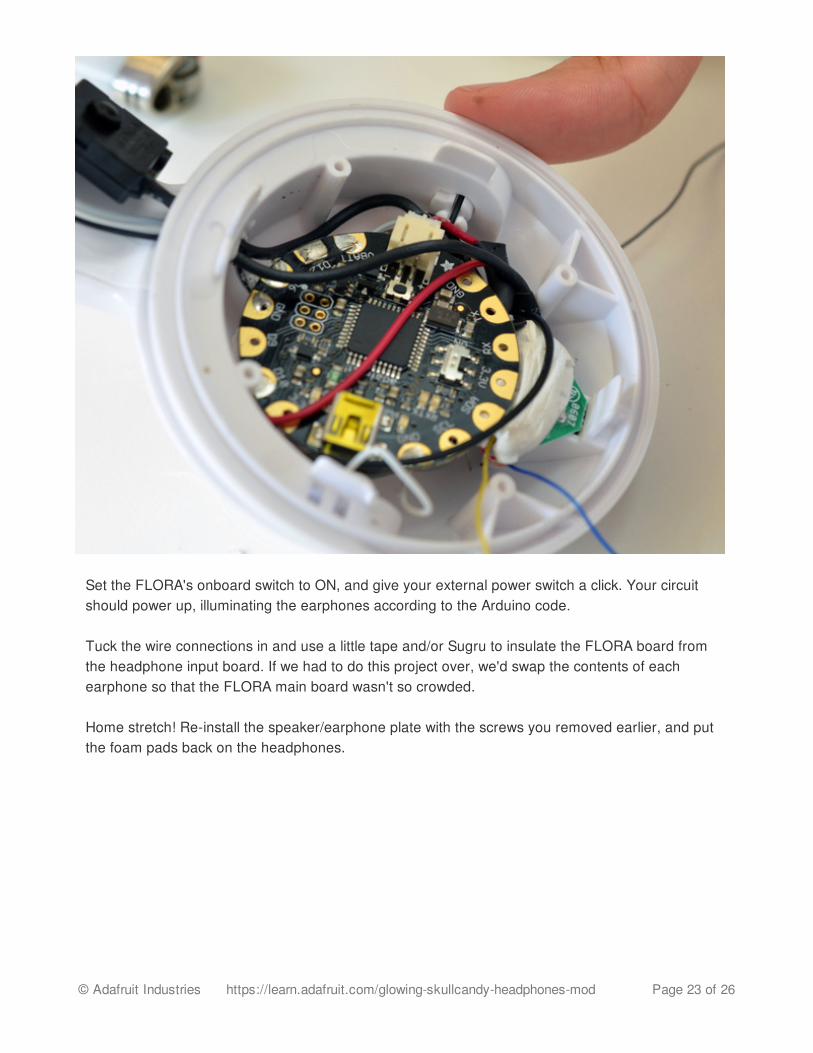
Set the FLORA's onboard switch to ON, and give your external power switch a click. Your circuitshould power up, illuminating the earphones according to the Arduino code.
Tuck the wire connections in and use a little tape and/or Sugru to insulate the FLORA board fromthe headphone input board. If we had to do this project over, we'd swap the contents of eachearphone so that the FLORA main board wasn't so crowded.
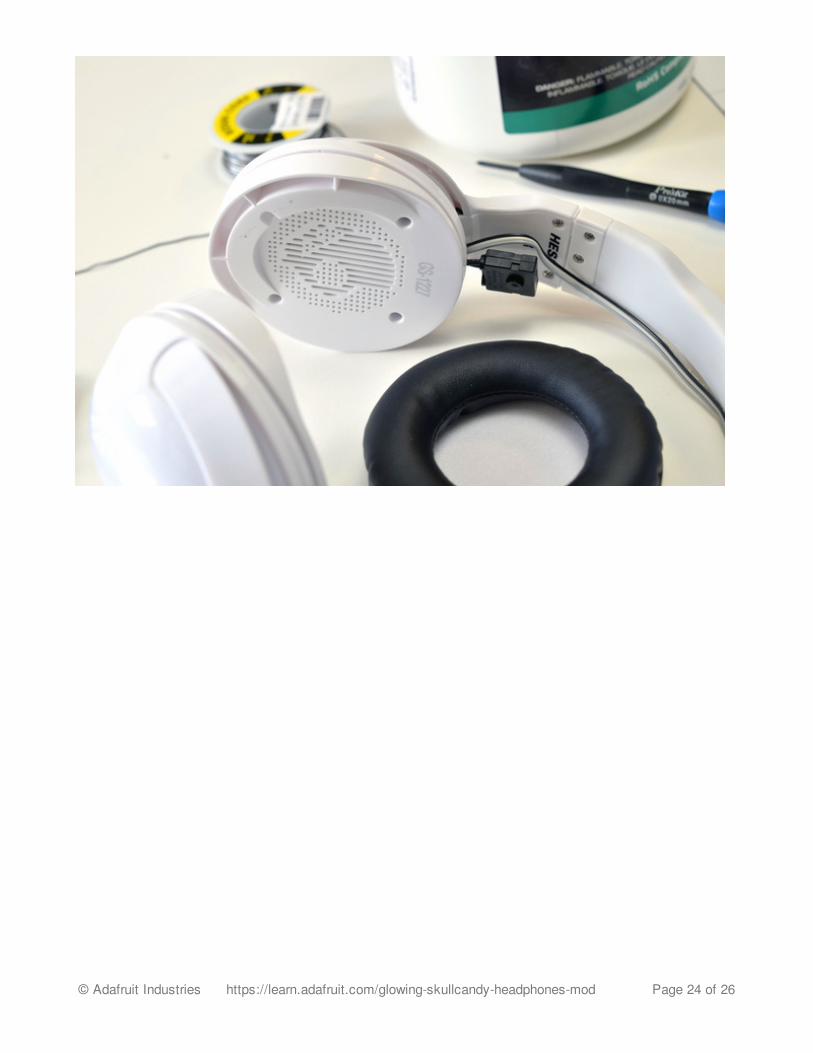
Home stretch! Re-install the speaker/earphone plate with the screws you removed earlier, and putthe foam pads back on the headphones.
© Adafruit Industries https://learn.adafruit.com/glowing-skullcandy-headphones-mod Page 23 of 26
© Adafruit Industries https://learn.adafruit.com/glowing-skullcandy-headphones-mod Page 24 of 26

Wear 'em!
Enjoy your new glowing headphones! Keep your volume down if you want to hear the complimentsyou'll get from passers-by.
To charge the battery or change the animations, you'll need to re-open the earphone containing theFLORA main board. Make sure your tactile switch is set to ON when charging the battery.
© Adafruit Industries https://learn.adafruit.com/glowing-skullcandy-headphones-mod Page 25 of 26
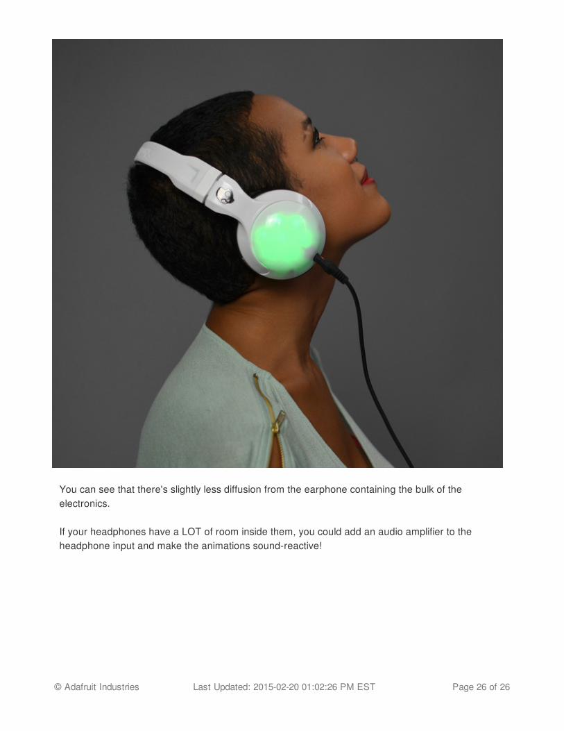
You can see that there's slightly less diffusion from the earphone containing the bulk of theelectronics.
If your headphones have a LOT of room inside them, you could add an audio amplifier to theheadphone input and make the animations sound-reactive!
© Adafruit Industries Last Updated: 2015-02-20 01:02:26 PM EST Page 26 of 26