global positioning system survey - famsi
TRANSCRIPT

430APPENDIX I
Global Positioning System Survey Chocolá Archaeological Site
17 November 2003 Wm. Clay Poe, Ph.D, RPA Professor of Archaeology Sonoma State University
Objectives The objective of the GPS survey project for 2003 was to define the locations of twelve concrete monuments placed as mapping and survey control points throughout the archaeological site of Chocolá for the Proyecto Arqueológico Chocolá (PACH), a long-term research project in the Guatemalan piedmont which is directed by Dr. Jonathan Kaplan of the University of New Mexico. Grid data The maps most commonly used by archaeologists in Guatemala are the 1:50,000 Universal Transverse Mercator Grid series prepared by the Instituto Geográfico Milatar (IGM) Guatemala, with the collaboration of the Defense Mapping Agency Inter American Geodetic Survey. These maps use the 1927 North American Datum (NAD27) as the horizontal datum and Mean Sea Level (MSL) as the vertical datum. These conventions provide a strong argument for reporting data in these same systems. However, there are even stronger reasons for favoring the current WGS84 datum with Height Above Ellipsoid (HAE) as the vertical reference. WGS84 is the native system for GPS receivers and the receivers compute the UTM coordinates and the HAE directly from the WGS84 Cartesian Geocentric Coordinates. GPS receivers and post-processing software translate from WGS84 to NAD27 as well as to other coordinate systems and refer to a database to convert from HAE to MSL or to a Geoid model to convert to Orthometric height. Not all equipment and software support well these legacy systems. The greatest consistency given a variety of equipment and software is obtained by adhering to the WGS84 datum. The grounds of consistency and equipment capacity are compelling for reporting the data in WGS84 datum with HAE as the vertical datum. Instrumentation and methodology The instrumentation and methodology for gathering field data in this project is based upon and consistent with the guidelines of a number of publications listed in the bibliography. The controlling documents have been the Federal Geodetic Control Subcommittee, Federal Geographic Data Committee (USA), Geospatial Positioning Accuracy Standards, Part 2: Standards for Geodetic Networks, FGDC-STD-007.2-1998, The Intergovernmental Committee on Surveying and Mapping (ICSM), (Australia), Best Practice Guidelines, Use of the Global Positioning System (GPS) for Surveying Applications, Version 2.0 - 1 November1997 and The National Geodetic Survey, (USA), Guidelines for Geodetic Network Surveys Using GPS. Draft 4, May 15, 2000. These document are current, are detailed in their description of appropriate field methods, and are appropriate to the equipment used in this survey project.
431
Instrumentation Three GPS receivers were used to collect the data for the control point survey. Two of the receivers are Trimble 4000SSE Geodetic Surveyors These are dual frequency L1/L2 receivers configured in this survey with geodetic antennas equipped with ground planes. Trimble specifies a horizontal accuracy of 5 mm + 1ppm times the baseline length and a vertical accuracy of 10 mm + 1ppm times the baseline length. The third receiver is a 4000SE GIS Surveyor. For this receiver Trimble specifies an accuracy of +/- 1 cm + 2ppm times the baseline length.1
The antennas were mounted on fixed length GPS rover poles stabilized with bipods. Field Methods
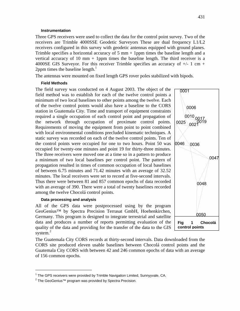
The field survey was conducted on 4 August 2003. The object of the field method was to establish for each of the twelve control points a minimum of two local baselines to other points among the twelve. Each of the twelve control points would also have a baseline to the CORS station in Guatemala City. Time and transport of equipment constraints required a single occupation of each control point and propagation of the network through occupation of proximate control points. Requirements of moving the equipment from point to point combined with local environmental conditions precluded kinematic techniques. A static survey was recorded on each of the twelve control points. Ten of the control points were occupied for one to two hours. Point 50 was occupied for twenty-one minutes and point 19 for thirty-three minutes. The three receivers were moved one at a time so in a pattern to produce a minimum of two local baselines per control point. The pattern of propagation resulted in times of common occupation of local baselines of between 6.75 minutes and 71.42 minutes with an average of 32.52 minutes. The local receivers were set to record at five-second intervals. Thus there were between 81 and 857 common epochs of data recorded with an average of 390. There were a total of twenty baselines recorded among the twelve Chocolá control points.
Data processing and analysis All of the GPS data were postprocessed using by the program GeoGenius™ by Spectra Precision Terrasat GmbH, Hoehenkirchen, Germany. This program is designed to integrate terrestrial and satellite data and produces a number of reports permitting evaluation of the quality of the data and providing for the transfer of the data to the GIS system.2
The Guatemala City CORS records at thirty-second intervals. Data downlCORS site produced eleven usable baselines between Chocolá control Guatemala City CORS with between 42 and 246 common epochs of data wof 156 common epochs.
1 The GPS receivers were provided by Trimble Navigation Limited, Sunnyyvale, CA. 2 The GeoGenius™ program was provided by Spectra Precision.
Fig 1 Chocolá control points
oaded from the points and the ith an average

432
The GeoGenius™ GPS postprocessing software computes the carrier phase solution to the baseline vector. The carrier signal from the satellite to the receiver consists of an integer number of complete cycles plus a fraction of a cycle. The GPS receiver can measure the time elapsed since the last phase shift in the carrier signal to about 1/100 of a cycle, that is near 2 mm for the 19 cm Ll carrier and the 23 cm L2 carrier. The unknown number of complete cycles between the satellite and the receiver is known as the integer ambiguity. Carrier phase processing software attempts to resolve this integer ambiguity. The principal sources of possible error in GPS positioning are ionospheric delay of the GPS signal and errors in the satellite and the receiver clocks. The amount of delay in the ionosphere is a function of the frequency of the signal. Using dual frequency receivers in conjunction with a model of the ionosphere effectively eliminates the error due to the ionosphere. Clock errors are eliminated by phase differencing techniques. Single differences are the differences between the carrier-phase observations of two receivers of the same satellite at the same epoch. Since the differences are of the same satellite, the satellite clock error is canceled. Double differences are the differences of two single differences of the same epoch that refer to two different satellites. Since double differences are from the same receiver, the receiver clock error is canceled. The triple difference is the difference between the double differences at two receivers, that is, the carrier-phase observations between two receivers, two satellites and two epochs. Because the integer ambiguity is a constant in time, the triple difference does not depend on this variable. The integer ambiguity only depends on the initial observation. The receiver keeps track of the number of whole cycles that it has received since first acquisition of the signal. The triple difference is used to detect and recover from cycle slips in the count. It also provides a first solution to the receiver position. With confidence in the cycle count, the program computes a double difference float solution. It is called a float solution because the integer ambiguities are permitted to float, that is the algorithm does not force them to be integers. The double difference solution allows processing correlated double difference carrier phase data. With dual-frequency data, additional baseline solutions will be provided for the various combinations of L1 and L2 known as Lw, Lc and Ln. A search for a more accurate solution is conducted within a window that is defined as twenty times the sigma value of the double difference float solution. The algorithm constrains the ambiguity to integers and searches the volume for the solution with the smallest sum of squares residual error. Statistical testing is used to verify the correctness of the ambiguity resolution. First a Fisher test is performed with the ratios of the variances of the second to the best fitting solution with a reliability requirement of 99.99%. Then a Chi-square test is performed on the a posteriori variance of the residuals with a default of a 95% minimum probability. If this process is successful the solution is said to be a fixed solution; if it is not successful the solution is said to be a float solution. Sixteen of the twenty local baselines at Chocolá and four of the ten baselines Guatemala City CORS are fixed solutions. Because of the degree of redundancy in the network, all of the control points are points on at least one fixed baseline. Two have one fixed local baseline and one of those has a fixed solution to Guatemala City CORS. Four of the control points have two local fixed baselines; two have three fixed baselines and four have four fixed baselines. This provides for a high degree of confidence in the accuracy and the precision of the network.
433
ArchMapBZ control point network accuracy and precision When used in the context of GPS mapping the accuracy refers to the confidence with which the absolute location of the receiver is known and the term precision refers to the confidence with which the base line between the base station and the rover is known.
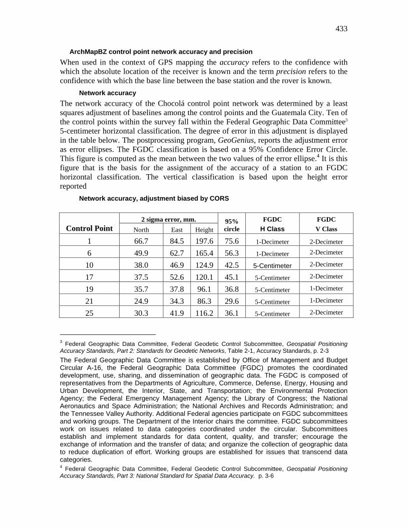
Network accuracy The network accuracy of the Chocolá control point network was determined by a least squares adjustment of baselines among the control points and the Guatemala City. Ten of the control points within the survey fall within the Federal Geographic Data Committee3 5-centimeter horizontal classification. The degree of error in this adjustment is displayed in the table below. The postprocessing program, GeoGenius, reports the adjustment error as error ellipses. The FGDC classification is based on a 95% Confidence Error Circle. This figure is computed as the mean between the two values of the error ellipse.4 It is this figure that is the basis for the assignment of the accuracy of a station to an FGDC horizontal classification. The vertical classification is based upon the height error reported
Network accuracy, adjustment biased by CORS
2 sigma error, mm. Control Point North East Height
95% circle
FGDC H Class
FGDC V Class
1 66.7 84.5 197.6 75.6 1-Decimeter 2-Decimeter
6 49.9 62.7 165.4 56.3 1-Decimeter 2-Decimeter
10 38.0 46.9 124.9 42.5 5-Centimeter 2-Decimeter
17 37.5 52.6 120.1 45.1 5-Centimeter 2-Decimeter
19 35.7 37.8 96.1 36.8 5-Centimeter 1-Decimeter
21 24.9 34.3 86.3 29.6 5-Centimeter 1-Decimeter
25 30.3 41.9 116.2 36.1 5-Centimeter 2-Decimeter
3 Federal Geographic Data Committee, Federal Geodetic Control Subcommittee, Geospatial Positioning Accuracy Standards, Part 2: Standards for Geodetic Networks, Table 2-1, Accuracy Standards, p. 2-3 The Federal Geographic Data Committee is established by Office of Management and Budget Circular A-16, the Federal Geographic Data Committee (FGDC) promotes the coordinated development, use, sharing, and dissemination of geographic data. The FGDC is composed of representatives from the Departments of Agriculture, Commerce, Defense, Energy, Housing and Urban Development, the Interior, State, and Transportation; the Environmental Protection Agency; the Federal Emergency Management Agency; the Library of Congress; the National Aeronautics and Space Administration; the National Archives and Records Administration; and the Tennessee Valley Authority. Additional Federal agencies participate on FGDC subcommittees and working groups. The Department of the Interior chairs the committee. FGDC subcommittees work on issues related to data categories coordinated under the circular. Subcommittees establish and implement standards for data content, quality, and transfer; encourage the exchange of information and the transfer of data; and organize the collection of geographic data to reduce duplication of effort. Working groups are established for issues that transcend data categories. 4 Federal Geographic Data Committee, Federal Geodetic Control Subcommittee, Geospatial Positioning Accuracy Standards, Part 3: National Standard for Spatial Data Accuracy. p. 3-6

434
36 28.6 39.2 100.6 33.9 5-Centimeter 2-Decimeter
46 27.8 38.2 96.3 33.0 5-Centimeter 1-Decimeter
47 29.6 40.0 103.5 34.8 5-Centimeter 2-Decimeter
48 34.9 43.5 113.7 39.2 5-Centimeter 2-Decimeter
50 42.4 49.0 124.4 45.7 5-Centimeter 2-Decimeter
GUAT 68.0 111.3 174.0 89.7 1-Decimeter 2-Decimeter
These data are within the Network Accuracy Standards minimally acceptable levels of differential relative positional accuracy required of a United States Government cadastral survey.5
ArchMapBZ control point coordinate values
Control Point WGS84 coordinates
Point Number X[m] Y[m] Z[m]
1 -154108.070 -6171630.157 1600741.029
6 -153946.352 -6171710.835 1600324.559
10 -153991.873 -6171749.464 1600108.722
17 -153730.608 -6171762.635 1600049.989
19 -153688.485 -6171782.943 1599972.674
21 -153885.308 -6171794.963 1599904.016
25 -154212.436 -6171770.002 1599958.785
36 -153870.771 -6171883.238 1599406.108
46 -154248.757 -6171870.408 1599430.753
47 -153386.706 -6171967.489 1599069.374
48 -153706.620 -6172074.446 1598430.012
50 -153732.105 -6172232.012 1597661.624
GUAT -56062.996 -6174980.368 1596665.507
Control Point UTM coordinates, latitude and longitude, WGS84, UTM 15N
Point
Number North[m] East[m] HAE Orthom. Height [m] Latitude Longitude
1 1617973.581 669048.916 923.002 923.542 N 14°37'47.53206" W 91°25'49.44451" 6 1617552.483 669215.485 891.961 892.511 N 14°37'33.79321" W 91°25'43.97581"
5 United States Department of Agriculture, Forest Service, United States Department of the Interior, Bureau of Land Management, Standards and Guidelines For Cadastral Surveys Using Global Positioning System Methods, March 21, 2001, p. 6.

435
10 1617333.339 669172.466 875.928 876.491 N 14°37'26.67259" W 91°25'45.46404" 17 1617276.653 669434.329 867.540 868.098 N 14°37'24.76914" W 91°25'36.72681" 19 1617197.294 669477.489 866.650 867.209 N 14°37'22.17728" W 91°25'35.30301" 21 1617125.241 669281.556 865.688 866.255 N 14°37'19.87709" W 91°25'41.86687" 25 1617180.196 668953.578 863.268 863.841 N 14°37'21.73902" W 91°25'52.81370" 36 1616621.490 669301.775 825.053 825.636 N 14°37'03.48189" W 91°25'41.30784" 46 1616643.574 668923.492 827.989 828.581 N 14°37'04.28557" W 91°25'53.94298" 47 1616280.877 669790.076 809.925 810.506 N 14°36'52.28914" W 91°25'25.07043" 48 1615631.138 669477.474 759.801 760.412 N 14°36'31.21902" W 91°25'35.66624" 50 1614847.696 669461.348 719.089 719.725 N 14°36'05.73166" W 91°25'36.38635"
GUAT 1614480.619 767173.488 1521.572 1519.880 N 14°35'25.44851" W 90°31'12.63839"

436
Appendix 1: GPS receivers
Geodetic surveyors
GPS Receiver
Trimble GPS Antenna
Trimble
Model 4000SSE Geodetic Surveyor Model Geodetic with ground plane Part No. 18292-01 Part No. 14177-00 Serial No. 3244A01763 Serial No. Firmware 7.29 GPS Receiver
Trimble GPS Antenna
Trimble
Model 4000SSE Geodetic Surveyor Model Geodetic with ground plane Part No. 18292-01 Part No. 14177-00 Serial No. 3610A14748 Serial No. 3017A00164 Firmware 7.29
GIS Surveyor
GPS Receiver
Trimble GPS Antenna
Trimble
Model 4000SE GIS Surveyor Model Compact L1 Part No. 18292-01 Part No. Serial No. 3301A02301 Serial No.
Firmware 7.23
437
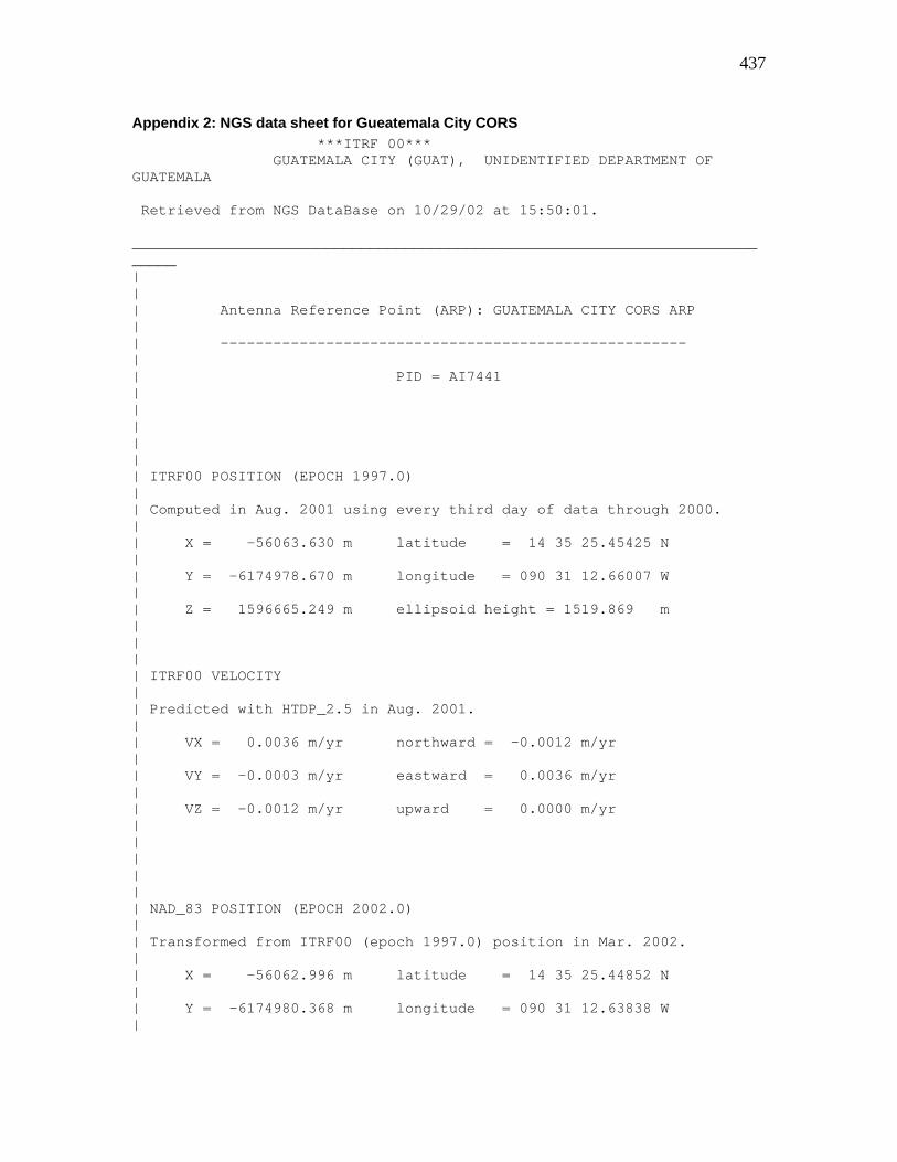
Appendix 2: NGS data sheet for Gueatemala City CORS ***ITRF 00*** GUATEMALA CITY (GUAT), UNIDENTIFIED DEPARTMENT OF GUATEMALA Retrieved from NGS DataBase on 10/29/02 at 15:50:01. ____________________________________________________________________________ | | | Antenna Reference Point (ARP): GUATEMALA CITY CORS ARP | | ----------------------------------------------------- | | PID = AI7441 | | | | | | ITRF00 POSITION (EPOCH 1997.0) | | Computed in Aug. 2001 using every third day of data through 2000. | | X = -56063.630 m latitude = 14 35 25.45425 N | | Y = -6174978.670 m longitude = 090 31 12.66007 W | | Z = 1596665.249 m ellipsoid height = 1519.869 m | | | | ITRF00 VELOCITY | | Predicted with HTDP_2.5 in Aug. 2001. | | VX = 0.0036 m/yr northward = -0.0012 m/yr | | VY = -0.0003 m/yr eastward = 0.0036 m/yr | | VZ = -0.0012 m/yr upward = 0.0000 m/yr | | | | | | NAD_83 POSITION (EPOCH 2002.0) | | Transformed from ITRF00 (epoch 1997.0) position in Mar. 2002. | | X = -56062.996 m latitude = 14 35 25.44852 N | | Y = -6174980.368 m longitude = 090 31 12.63838 W |
438
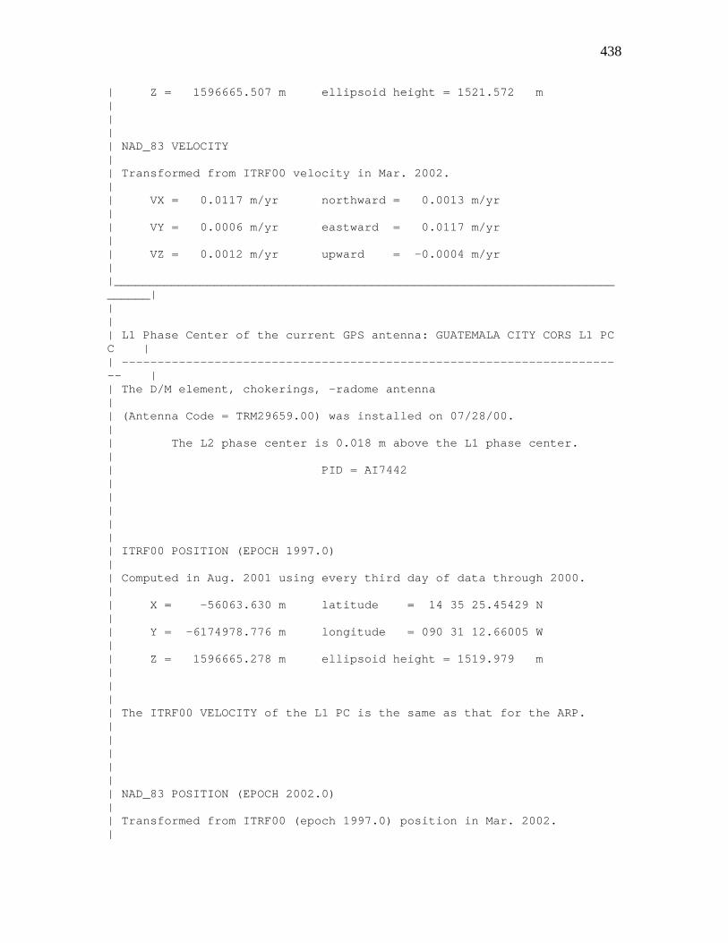
| Z = 1596665.507 m ellipsoid height = 1521.572 m | | | | NAD_83 VELOCITY | | Transformed from ITRF00 velocity in Mar. 2002. | | VX = 0.0117 m/yr northward = 0.0013 m/yr | | VY = 0.0006 m/yr eastward = 0.0117 m/yr | | VZ = 0.0012 m/yr upward = -0.0004 m/yr | |____________________________________________________________________________| | | | L1 Phase Center of the current GPS antenna: GUATEMALA CITY CORS L1 PC C | | ----------------------------------------------------------------------- | | The D/M element, chokerings, -radome antenna | | (Antenna Code = TRM29659.00) was installed on 07/28/00. | | The L2 phase center is 0.018 m above the L1 phase center. | | PID = AI7442 | | | | | | ITRF00 POSITION (EPOCH 1997.0) | | Computed in Aug. 2001 using every third day of data through 2000. | | X = -56063.630 m latitude = 14 35 25.45429 N | | Y = -6174978.776 m longitude = 090 31 12.66005 W | | Z = 1596665.278 m ellipsoid height = 1519.979 m | | | | The ITRF00 VELOCITY of the L1 PC is the same as that for the ARP. | | | | | | NAD_83 POSITION (EPOCH 2002.0) | | Transformed from ITRF00 (epoch 1997.0) position in Mar. 2002. |

439
| X = -56062.996 m latitude = 14 35 25.44856 N | | Y = -6174980.474 m longitude = 090 31 12.63836 W | | Z = 1596665.536 m ellipsoid height = 1521.682 m | | | | The NAD_83 VELOCITY of the L1 PC is the same as that for the ARP. | |____________________________________________________________________________| * Latitude, longitude and ellipsoid height are computed from their corresponding cartesian coordinates using dimensions for the GRS 80 ellipsoid: semi-major axis = 6,378,137.0 meters flattening = 1/298.257222101...\other relevant points at the site and on GPS equipment, consult the link ftp://www.ngs.noaa.gov/cors/.html/guat.log.txt * The NAD_83 position & velocity were revised in Mar. 2002.

440
Bibliography United States Department of Agriculture, Forest Service, United States Department of the Interior, Bureau of Land Management, Standards and Guidelines For Cadastral Surveys Using Global Positioning System Methods, March 21, 2001. The Intergovernmental Committee on Surveying and Mapping (ICSM), Australia, Best Practice Guidelines, Use of the Global Positioning System (GPS) for Surveying Applications, Version 2.0 - 1 November1997 US Army Corps of Engineers, Engineering And Design, NAVSTAR Global Positioning System Surveying Engineer Manual, EM 1110-1-1003, 1 August 1996 National Geodetic Survey, Guidelines for Geodetic Network Surveys Using GPS, Including Federal & Cooperative Base Network Surveys, User Densification Network Surveys, Gps Orthometric Height Surveys, DRAFT 4, May 15, 2000, National Geodetic Survey, N/NGS2, NOAA, 1315 East-West Highway, Silver Spring, Maryland 20910-3282, email: [email protected] or [email protected] Birchall, C. J. and R. N. Jenkin, The Soils of the Belize Valley, Belize, Vol. 1 and 2, Land Resources Development Centre, Supplementary Report 15, 1979.

Dr. Jonathan Kaplan Report Date: 12/20/2004
Material Received: 11/17/2004
Sample Data Measured 13C/12C Conventional Radiocarbon Age Ratio Radiocarbon Age(*)
Beta - 198188 2240 +/- 40 BP -25.6 o/oo 2230 +/- 40 BP SAMPLE : 4-72-4 211 ANALYSIS : AMS-Standard delivery MATERIAL/PRETREATMENT : (charred material): acid/alkali/acid 2 SIGMA CALIBRATION : Cal BC 390 to 190 (Cal BP 2340 to 2140) ____________________________________________________________________________________ Beta - 198189 2220 +/- 60 BP -26.5 o/oo 2200 +/- 60 BP SAMPLE : 4-72-5 258 ANALYSIS : Radiometric-Standard delivery (with extended counting) MATERIAL/PRETREATMENT : (charred material): acid/alkali/acid 2 SIGMA CALIBRATION : Cal BC 390 to 80 (Cal BP 2340 to 2030) ____________________________________________________________________________________ Beta - 198190 2250 +/- 40 BP -28.2 o/oo 2200 +/- 40 BP SAMPLE : 4-72-6 260 ANALYSIS : AMS-Standard delivery MATERIAL/PRETREATMENT : (charred material): acid/alkali/acid 2 SIGMA CALIBRATION : Cal BC 380 to 160 (Cal BP 2330 to 2120) ____________________________________________________________________________________ Beta - 198191 2240 +/- 40 BP -28.5 o/oo 2180 +/- 40 BP SAMPLE : 4-72-7 262 ANALYSIS : AMS-Standard delivery MATERIAL/PRETREATMENT : (charred material): acid/alkali/acid 2 SIGMA CALIBRATION : Cal BC 370 to 110 (Cal BP 2320 to 2060) ____________________________________________________________________________________ Beta - 198192 2250 +/- 110 BP -27.5 o/oo 2210 +/- 110 BP SAMPLE : 4-72-8 264 ANALYSIS : Radiometric-Standard delivery (with extended counting) MATERIAL/PRETREATMENT : (charred material): acid/alkali/acid 2 SIGMA CALIBRATION : Cal BC 500 to 460 (Cal BP 2450 to 2410) AND Cal BC 430 to Cal AD 20 (Cal BP 2380 to 1930) ____________________________________________________________________________________

Dr. Jonathan Kaplan Report Date: 12/20/2004
Sample Data Measured 13C/12C Conventional Radiocarbon Age Ratio Radiocarbon Age(*)
Beta - 198194 2220 +/- 40 BP -26.7 o/oo 2190 +/- 40 BP SAMPLE : 4-91-6 231 ANALYSIS : AMS-Standard delivery MATERIAL/PRETREATMENT : (charred material): acid/alkali/acid 2 SIGMA CALIBRATION : Cal BC 380 to 160 (Cal BP 2330 to 2100) ____________________________________________________________________________________ Beta - 198196 2120 +/- 40 BP -24.9 o/oo 2120 +/- 40 BP SAMPLE : 4-91-8 235 ANALYSIS : AMS-Standard delivery MATERIAL/PRETREATMENT : (charred material): acid/alkali/acid 2 SIGMA CALIBRATION : Cal BC 350 to 310 (Cal BP 2300 to 2260) AND Cal BC 210 to 40 (Cal BP 2160 to 1990) ____________________________________________________________________________________

CALIB RATION OF RADIOCARBON AGE TO C ALEND AR Y EARS(Variables: C1 3/C12=-25.6:lab. m ult=1)
La borato ry number: Beta-198 188
Conventio nal radio ca rbon ag e: 223 0±40 BP2 Sigma calibra ted result:
(95% pro ba bility)Ca l BC 390 to 190 (Ca l BP 2 340 to 2 140 )
In tercept dataIntercep ts o f radiocarbo n ag e
with calibratio n cu rve: Cal BC 36 0 (Cal BP 231 0) andCal BC 28 0 (Cal BP 223 0) andCal BC 24 0 (Cal BP 219 0)
1 Sigm a calibrated resu lts:(68% probability)
Cal BC 38 0 to 3 40 (Cal BP 23 30 to 229 0) andCal BC 32 0 to 2 10 (Cal BP 22 70 to 216 0)
4 98 5 S .W . 7 4th Co u rt, M ia mi, F lor id a 33 1 55 • Tel: (3 0 5) 66 7- 51 67 • Fa x: ( 30 5) 66 3 -09 6 4 • E -M ail: beta @ra dio ca rbo n.co mBeta Analytic Rad iocarbon Dating Laborato ry
T alm a, A. S., Voge l, J . C., 1993, Radioc arbon 35(2) , p317-322A S impl ifi ed App roach to Cali bratin g C14 D atesM ath em atic s
Stui ve r, M., e t. al., 1998, Radi ocarbon 40(3), p1041 -1083IN TCAL98 Radi ocarbon Age Calibrat ion
Stui ve r, M., v an der P l icht, H ., 1998, Radioc arbon 40(3), px ii-xi iiEdi torial C omme ntCal ibration D atabase
INT CAL98D atabase use d
References:
Rad
ioca
rbon
age
(BP
)
2080
2100
2120
2140
2160
2180
2200
2220
2240
2260
2280
2300
2320
2340
Charred m ateria l2360
Cal B C400 380 360 340 320 300 280 260 240 220 200 180
2230±40 B P

CALIB RATION OF RADIOCARBON AGE TO C ALEND AR Y EARS(Variables: C1 3/C12=-26.5:lab. m ult=1)
La borato ry number: Beta-198 189
Conventio nal radio ca rbon ag e: 220 0±60 BP2 Sigma calibra ted result:
(95% pro ba bility)Ca l BC 390 to 80 (Cal BP 23 40 to 20 30)
In tercept dataIntercep ts o f radiocarbo n ag e
with calibratio n cu rve: Cal BC 35 0 (Cal BP 230 0) andCal BC 31 0 (Cal BP 226 0) andCal BC 21 0 (Cal BP 216 0)
1 Sigm a calibrated resu lt:(68% probability)
Cal BC 37 0 to 1 80 (Cal BP 23 20 to 213 0)
4 98 5 S .W . 7 4th Co u rt, M ia mi, F lor id a 33 1 55 • Tel: (3 0 5) 66 7- 51 67 • Fa x: ( 30 5) 66 3 -09 6 4 • E -M ail: beta @ra dio ca rbo n.co mBeta Analytic Rad iocarbon Dating Laborato ry
T alm a, A. S., Voge l, J . C., 1993, Radioc arbon 35(2) , p317-322A S impl ifi ed App roach to Cali bratin g C14 D atesM ath em atic s
Stui ve r, M., e t. al., 1998, Radi ocarbon 40(3), p1041 -1083IN TCAL98 Radi ocarbon Age Calibrat ion
Stui ve r, M., v an der P l icht, H ., 1998, Radioc arbon 40(3), px ii-xi iiEdi torial C omme ntCal ibration D atabase
INT CAL98D atabase use d
References:
Rad
ioca
rbon
age
(BP
)
1950
2000
2050
2100
2150
2200
2250
2300
2350
Charred m ateria l2400
Cal B C450 400 350 300 250 200 150 100 50
2200±60 B P

CALIB RATION OF RADIOCARBON AGE TO C ALEND AR Y EARS(Variables: C1 3/C12=-28.2:lab. m ult=1)
La borato ry number: Beta-198 190
Conventio nal radio ca rbon ag e: 220 0±40 BP2 Sigma calibra ted result:
(95% pro ba bility)Ca l BC 380 to 160 (Ca l BP 2 330 to 2 120 )
In tercept dataIntercep ts o f radiocarbo n ag e
with calibratio n cu rve: Cal BC 35 0 (Cal BP 230 0) andCal BC 31 0 (Cal BP 226 0) andCal BC 21 0 (Cal BP 216 0)
1 Sigm a calibrated resu lt:(68% probability)
Cal BC 36 0 to 1 90 (Cal BP 23 20 to 214 0)
4 98 5 S .W . 7 4th Co u rt, M ia mi, F lor id a 33 1 55 • Tel: (3 0 5) 66 7- 51 67 • Fa x: ( 30 5) 66 3 -09 6 4 • E -M ail: beta @ra dio ca rbo n.co mBeta Analytic Rad iocarbon Dating Laborato ry
T alm a, A. S., Voge l, J . C., 1993, Radioc arbon 35(2) , p317-322A S impl ifi ed App roach to Cali bratin g C14 D atesM ath em atic s
Stui ve r, M., e t. al., 1998, Radi ocarbon 40(3), p1041 -1083IN TCAL98 Radi ocarbon Age Calibrat ion
Stui ve r, M., v an der P l icht, H ., 1998, Radioc arbon 40(3), px ii-xi iiEdi torial C omme ntCal ibration D atabase
INT CAL98D atabase use d
References:
Rad
ioca
rbon
age
(BP
)
2060
2080
2100
2120
2140
2160
2180
2200
2220
2240
2260
2280
2300
2320
Charred m ateria l2340
Cal B C400 380 360 340 320 300 280 260 240 220 200 180 160 140
2200±40 B P
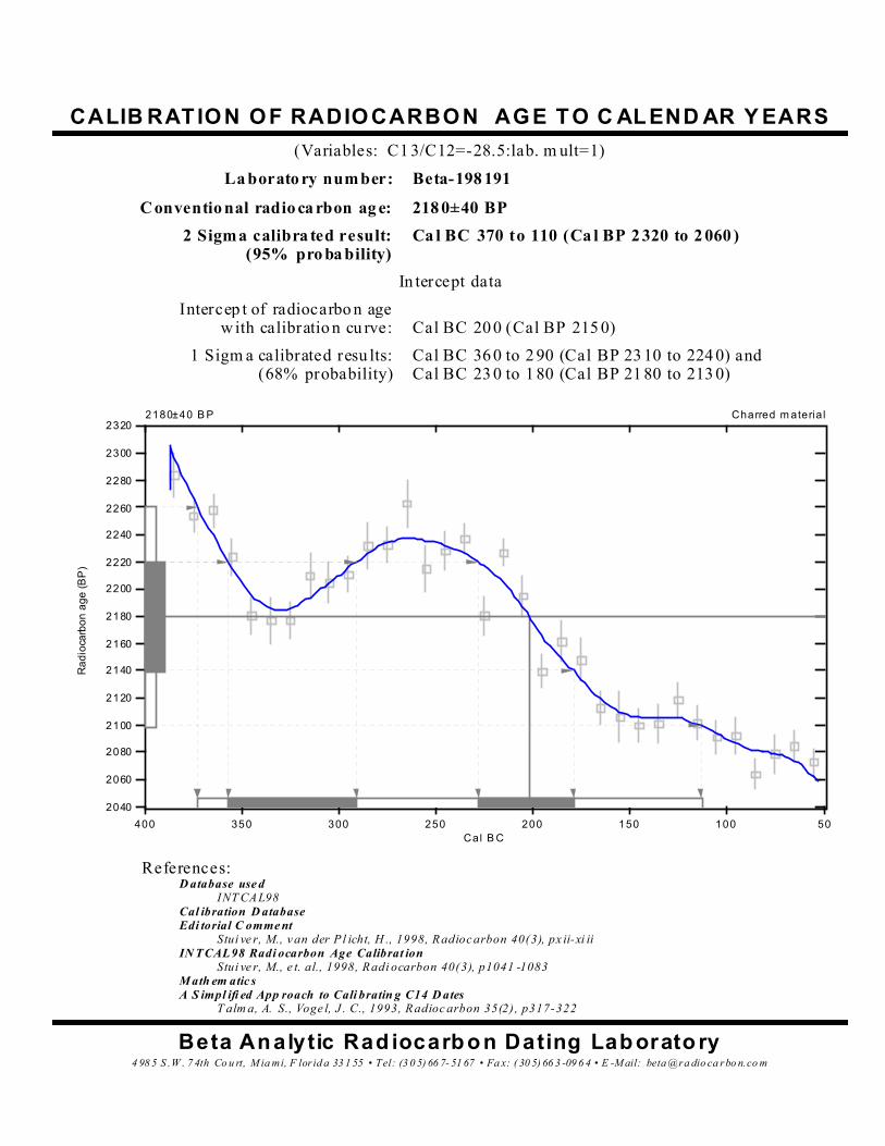
CALIB RATION OF RADIOCARBON AGE TO C ALEND AR Y EARS(Variables: C1 3/C12=-28.5:lab. m ult=1)
La borato ry number: Beta-198 191
Conventio nal radio ca rbon ag e: 218 0±40 BP2 Sigma calibra ted result:
(95% pro ba bility)Ca l BC 370 to 110 (Ca l BP 2 320 to 2 060 )
In tercept dataIntercep t of radiocarbo n age
with calibratio n cu rve: Cal BC 20 0 (Cal BP 215 0)1 Sigm a calibrated resu lts:
(68% probability)Cal BC 36 0 to 2 90 (Cal BP 23 10 to 224 0) andCal BC 23 0 to 1 80 (Cal BP 21 80 to 213 0)
4 98 5 S .W . 7 4th Co u rt, M ia mi, F lor id a 33 1 55 • Tel: (3 0 5) 66 7- 51 67 • Fa x: ( 30 5) 66 3 -09 6 4 • E -M ail: beta @ra dio ca rbo n.co mBeta Analytic Rad iocarbon Dating Laborato ry
T alm a, A. S., Voge l, J . C., 1993, Radioc arbon 35(2) , p317-322A S impl ifi ed App roach to Cali bratin g C14 D atesM ath em atic s
Stui ve r, M., e t. al., 1998, Radi ocarbon 40(3), p1041 -1083IN TCAL98 Radi ocarbon Age Calibrat ion
Stui ve r, M., v an der P l icht, H ., 1998, Radioc arbon 40(3), px ii-xi iiEdi torial C omme ntCal ibration D atabase
INT CAL98D atabase use d
References:
Rad
ioca
rbon
age
(BP
)
2040
2060
2080
2100
2120
2140
2160
2180
2200
2220
2240
2260
2280
2300
Charred m ateria l2320
Cal B C400 350 300 250 200 150 100 50
2180±40 B P

CALIBRATION O F RADIOCARBO N AGE TO CALENDAR YEARS(Variables: C13/C12=-27.5:lab. mult=1)
La borato ry num ber: Beta-1981 92
Conventio nal radiocarbon age: 2210±110 BP2 Sigma calibrated results:
(95% probability)Cal BC 500 to 460 (Cal BP 2 450 to 2410) andCal BC 430 to C al AD 2 0 (Cal BP 238 0 to 19 30)
In tercep t dataIntercepts of radiocarbon age
with calibration curve: Cal BC 350 (Cal BP 2300 ) andCal BC 300 (Cal BP 2250 ) andCal BC 220 (Cal BP 2170 )
1 Sigma calibrated result:(68% probability)
Cal BC 390 to 11 0 (Cal BP 2340 to 206 0)
4 98 5 S.W . 7 4th Co ur t, M iam i, Flor id a 33 15 5 • T el: (3 05 )66 7- 51 67 • F ax: (3 05 )6 63 -09 64 • E-M ail: b eta@r a dio car bo n.co mBeta Ana lytic Radio carbo n Datin g Laboratory
T alma, A . S ., V ogel, J . C., 1993, R adiocarbon 35(2), p317-322A Sim pl ifie d Approac h to Calibratin g C14 D atesM athe matics
Stuiv er, M., e t. a l., 1998, R adiocarbon 40(3), p1041-1083INT CAL 98 Radiocarbon Age C al ibration
Stuiv er, M., v an de r Pl icht, H ., 1998, R adi oc arbon 40(3) , pxii -xi iiEditorial Comm entCalibration D atabase
INTC AL 98Database u sed
References:
Rad
ioca
rbon
age
(BP)
1 700
1800
1900
2000
2100
2200
2300
2400
2500
Char red m ate rial2600
C a l B C/AD550 500 450 400 350 300 250 200 150 100 50 0 50
2210±110 BP

CALIB RATION OF RADIOCARBON AGE TO C ALEND AR Y EARS(Variables: C1 3/C12=-26.7:lab. m ult=1)
La borato ry number: Beta-198 194
Conventio nal radio ca rbon ag e: 219 0±40 BP2 Sigma calibra ted result:
(95% pro ba bility)Ca l BC 380 to 160 (Ca l BP 2 330 to 2 100 )
In tercept dataIntercep ts o f radiocarbo n ag e
with calibratio n cu rve: Cal BC 34 0 (Cal BP 229 0) andCal BC 32 0 (Cal BP 227 0) andCal BC 21 0 (Cal BP 216 0)
1 Sigm a calibrated resu lts:(68% probability)
Cal BC 36 0 to 2 80 (Cal BP 23 10 to 223 0) andCal BC 24 0 to 1 90 (Cal BP 21 90 to 214 0)
4 98 5 S .W . 7 4th Co u rt, M ia mi, F lor id a 33 1 55 • Tel: (3 0 5) 66 7- 51 67 • Fa x: ( 30 5) 66 3 -09 6 4 • E -M ail: beta @ra dio ca rbo n.co mBeta Analytic Rad iocarbon Dating Laborato ry
T alm a, A. S., Voge l, J . C., 1993, Radioc arbon 35(2) , p317-322A S impl ifi ed App roach to Cali bratin g C14 D atesM ath em atic s
Stui ve r, M., e t. al., 1998, Radi ocarbon 40(3), p1041 -1083IN TCAL98 Radi ocarbon Age Calibrat ion
Stui ve r, M., v an der P l icht, H ., 1998, Radioc arbon 40(3), px ii-xi iiEdi torial C omme ntCal ibration D atabase
INT CAL98D atabase use d
References:
Rad
ioca
rbon
age
(BP
)
2040
2060
2080
2100
2120
2140
2160
2180
2200
2220
2240
2260
2280
2300
Charred m ateria l2320
Cal B C400 380 360 340 320 300 280 260 240 220 200 180 160 140 120
2190±40 B P

CALIB RATION OF RADIOCARBON AGE TO C ALEND AR Y EARS(Variables: C1 3/C12=-24.9:lab. m ult=1)
La borato ry number: Beta-198 196
Conventio nal radio ca rbon ag e: 212 0±40 BP2 Sigma calibra ted results:
(95% pro ba bility)Ca l BC 350 to 310 (Ca l BP 2 300 to 2 260 ) andCa l BC 210 to 40 (Cal BP 21 60 to 19 90)
In tercept dataIntercep t of radiocarbo n age
with calibratio n cu rve: Cal BC 16 0 (Cal BP 212 0)1 Sigm a calibrated resu lt:
(68% probability)Cal BC 19 0 to 8 0 (Cal BP 214 0 to 2030 )
4 98 5 S .W . 7 4th Co u rt, M ia mi, F lor id a 33 1 55 • Tel: (3 0 5) 66 7- 51 67 • Fa x: ( 30 5) 66 3 -09 6 4 • E -M ail: beta @ra dio ca rbo n.co mBeta Analytic Rad iocarbon Dating Laborato ry
T alm a, A. S., Voge l, J . C., 1993, Radioc arbon 35(2) , p317-322A S impl ifi ed App roach to Cali bratin g C14 D atesM ath em atic s
Stui ve r, M., e t. al., 1998, Radi ocarbon 40(3), p1041 -1083IN TCAL98 Radi ocarbon Age Calibrat ion
Stui ve r, M., v an der P l icht, H ., 1998, Radioc arbon 40(3), px ii-xi iiEdi torial C omme ntCal ibration D atabase
INT CAL98D atabase use d
References:
Rad
ioca
rbon
age
(BP
)
1980
2000
2020
2040
2060
2080
2100
2120
2140
2160
2180
2200
2220
2240
Charred m ateria l2260
Cal B C/AD400 350 300 250 200 150 100 50 0
2120±40 B P

Field Methodology, Mound 5, Chocolá, 2004 Season
La operación sobre el Montículo 15 fue abreviada en la nomenclatura de PACH
como Operación 14. Features on Mound 5 which had been discovered during the
2003 season and which were suggestive of permanent architecture were
deemed sufficiently interesting to explore in a fuller manner in 2004. The decision
was taken to undertake intensive excavations employing a Cartesian grid system
of 2 x 2 m grid units. In similar manner to that described above for excavations
on Mound 15, JK instructed David Monsees to gradiometrically prospect the
mound to help decide where to begin excavations, in this case out and around
from the stone alignment discovered during the last days of the 2003 season,
and which lay approximately one m below ground surface toward the east off the
gentle slope of Mound 5. Using a total station a permanent benchmark (BM 50)
anchored the shooting in of datums and subdatums to create the grid. The
original 20 x 20 m grid, established with stakes and triangulation, reading from
the total-station located datums and subdatums, later was expanded such that
several 20 x 20 m grids around the original were established during the course of
the excavations as necessary dependent on the findings below ground of what
turned out to be a massive stone-walled platform structure extending from the
furthermost east point – the east wall of which part belonged to the 2003 feature
– 45 m west to the west wall and, to the north, from the north wall 40 m south to
what we believe constitutes the south wall, based on the finding of an apparent
southeast corner. The entire structure – if our estimated dimensions and
orientations are correct – constitutes nearly the entirety of the topographically
elevated Mound 5, with some allowance for collapse and other taphonomic
processes such as crop turbation, other human interventions and disturbances,
chiefly agricultural, and millennia of weather and longer-term geophysical cycles
and events.
Once gradiometric prospection had been completed and hot-spots noted,
excavation was guided by prompt discoveries of major cobble wall architecture,
with the north wall emerging first, followed by the east wall. Continuing to adhere
to a Cartesian grid unit procedure – rather than, as is sometimes practiced in the
lowlands, by excavating architecture without a systematic grid recovery of
information – excavators were instructed to pursue by grid units west along the
north wall and south along the east wall. In this manner, precise provenience
information was obtained, controlled by constant tie-in to datums which had
precisely known locations through measurements with the total station and by
relation to BM 50.
In addition to seeking horizontally to delineate the outline of the platform,
at least once the probable floor contemporary with the first course of the eight-
course north wall was reached, vertical or diachronic investigations were
undertaken, the location selected being the center of the mound. However, these
latter investigations also ceased with discovery of a major burned clay feature;
further investigations of this feature are contemplated for the future. These
central pits, like all the other units, were tied in to the absolute locations known
from BM 50.