glc - mercedes-benz usaglc operator'smanual youroperator'smanual...
TRANSCRIPT

GLCOperator's Manual
Your Operator's Manual
Digital form inside the vehicleFamiliarize yourself with the contents of the Operator's Manual directly via yourvehicle's multimedia system (Menu item "Vehicle").
Booklet inside the vehicleIn addition to the vehicle's Operator's Manual, you can obtain the complete multi-media system Supplement from your authorized Mercedes-Benz Center.
Digital form via the InternetYou can find the Operator's Manual on the Mercedes-Benz homepage.
Digital form as an AppTheMercedes-BenzGuidesApp is available for free on theApple®App store orGooglePlay.
Apple® iOS Android™
Order no. P253 0317 13 Part no. 253 584 29 02 Edition B 2017
É2535842902^ËÍ2535842902
GLCO
perat
or'sM
anual
Publication detailsInternet
Further information about Mercedes-Benz vehi-cles and about Daimler AG can be found on thefollowing websites:http://www.mbusa.com (USA only)http://www.mercedes-benz.ca (Canada only)
Editorial office
Daimler AG: not to be reprinted, translated orotherwise reproduced, in whole or in part, with-out written permission from Daimler AG.
Vehicle manufacturer
Daimler AGMercedesstra e 13770327 StuttgartGermany
SymbolsRegistered trademarks:RBluetooth® is a registered trademark of Blue-tooth SIG Inc.RDTS™ is a registered trademark of DTS, Inc.RDolby® and MLP™ are registered trademarksof DOLBY Laboratories.RBabySmart™, ESP® and PRE-SAFE® are reg-istered trademarks of Daimler AG.RHomeLink® is a registered trademark of John-son Controls.RiPod® and iTunes® are registered trademarksof Apple Inc.RBurmester® is a registered trademark ofBurmester Audiosysteme GmbH.RMicrosoft® and Windows media® are regis-tered trademarks of Microsoft Corporation.RSIRIUS® is a registered trademark of SiriusXM Radio Inc.RHD Radio™ is a registered trademark of iBiq-uity Digital Corporation.RGracenote® is a registered trademark ofGracenote, Inc.RZAGAT Survey® and related brands are regis-tered trademarks of Zagat Survey, LLC.
In this Operator's Manual you will find the fol-lowing symbols:
G WARNINGWarning notes make you aware of dangerswhich could pose a threat to your health orlife, or to the health and life of others.
H Environmental noteEnvironmental notes provide you with infor-mation on environmentally aware actions ordisposal.
! Notes on material damage alert you to dan-gers that could lead to damage to your vehi-cle.
i Practical tips or further information thatcould be helpful to you.
X This symbol indicates aninstruction that must be fol-lowed.
X Several of these symbols insuccession indicate an
instruction with severalsteps.
(Ypage)
This symbol tells you whereyou can find more informa-tion about a topic.
YY This symbol indicates awarning or an instructionthat is continued on the nextpage.
Dis‐play This text indicates a mes-sage on the multifunctiondisplay/multimedia display.
As at 08.04.2016

Welcome to the world of Mercedes-BenzWe urge you to read this Operator's Manualcarefully and familiarize yourself with the vehi-cle before driving. For your own safety and alonger vehicle life, follow the instructions andwarning notices in this Operator's Manual.Ignoring them could result in damage to thevehicle or personal injury to you or others.Vehicle damage caused by failure to followinstructions is not covered by the Mercedes-Benz Limited Warranty.The equipment or product designation of yourvehicle may vary depending on:RModelROrderRCountry specificationRAvailabilityMercedes-Benz therefore reserves the right tointroduce changes in the following areas:RDesignREquipmentRTechnical featuresThe equipment in your vehicle may thereforediffer from that shown in the descriptions andillustrations.The following are integral components of thevehicle:RDigital Operator's ManualRPrinted Operator's ManualRMaintenance BookletREquipment-dependent supplementsKeep these documents in the vehicle at alltimes. If you sell the vehicle, always pass alldocuments on to the new owner.Your Operator's Manual:
Digital form inside the vehicleThe Digital Operator's Manual providescomprehensive and specifically adaptedinformation on your vehicle's equipmentand multimedia system. It contains infor-mative animations, individual languagesettings and an intuitive search function.Booklet inside the vehicleIn addition to this manual and the afore-mentioned digital media, you also have theoption to obtain a comprehensive printedversion of the Supplement for your multi-media system from your authorizedMercedes-Benz Center.
Digital form via the InternetTheOperator'sManual on the Internet pro-vides easy access to all informationregarding your vehicle andmultimedia sys-tem. It also provides helpful animations,interesting background information and awide array of search options.Digital form as an AppUsing the Mercedes-Benz Guides App, youcan view all the information on your vehicleandmultimedia system via mobile Internetor download it independently of networkaccess. Available for smartphones or tab-lets.
Please note that theMercedes-Benz Guides Appmay not yet be available in your country.Mercedes-Benz USA, LLCMercedes-Benz Canada, Inc.A Daimler Company
2535842902 É2535842902^ËÍ
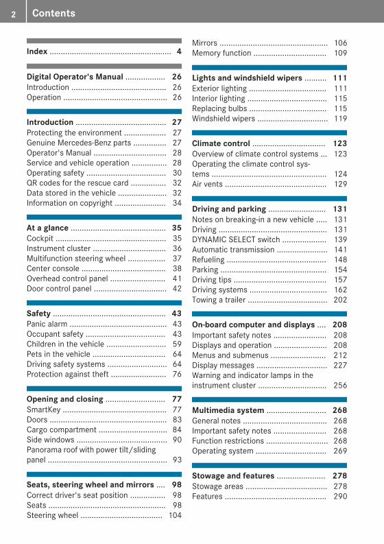
Index ....................................................... 4
Digital Operator's Manual .................. 26Introduction ........................................... 26Operation ............................................... 26
Introduction ......................................... 27Protecting the environment ................... 27Genuine Mercedes-Benz parts ............... 27Operator's Manual ................................. 28Service and vehicle operation ................ 28Operating safety .................................... 30QR codes for the rescue card ................ 32Data stored in the vehicle ...................... 32Information on copyright ....................... 34
At a glance ........................................... 35Cockpit .................................................. 35Instrument cluster ................................. 36Multifunction steering wheel ................. 37Center console ...................................... 38Overhead control panel ......................... 41Door control panel ................................. 42
Safety ................................................... 43Panic alarm ............................................ 43Occupant safety .................................... 43Children in the vehicle ........................... 59Pets in the vehicle ................................. 64Driving safety systems ........................... 64Protection against theft ......................... 76
Opening and closing ........................... 77SmartKey ............................................... 77Doors ..................................................... 83Cargo compartment ............................... 84Side windows ......................................... 90Panorama roof with power tilt/slidingpanel ...................................................... 93
Seats, steering wheel and mirrors .... 98Correct driver's seat position ................ 98Seats ..................................................... 98Steering wheel ..................................... 104
Mirrors ................................................. 106Memory function ................................. 109
Lights and windshield wipers .......... 111Exterior lighting ................................... 111Interior lighting .................................... 115Replacing bulbs ................................... 115Windshield wipers ................................ 119
Climate control ................................. 123Overview of climate control systems ... 123Operating the climate control sys-tems .................................................... 124Air vents .............................................. 129
Driving and parking .......................... 131Notes on breaking-in a new vehicle ..... 131Driving ................................................. 131DYNAMIC SELECT switch .................... 139Automatic transmission ....................... 141Refueling ............................................. 148Parking ................................................ 154Driving tips .......................................... 157Driving systems ................................... 162Towing a trailer .................................... 202
On-board computer and displays .... 208Important safety notes ........................ 208Displays and operation ........................ 208Menus and submenus ......................... 212Display messages ................................ 227Warning and indicator lamps in theinstrument cluster ............................... 256
Multimedia system ........................... 268General notes ...................................... 268Important safety notes ........................ 268Function restrictions ............................ 268Operating system ................................ 269
Stowage and features ...................... 278Stowage areas ..................................... 278Features .............................................. 290
2 Contents

Maintenance and care ...................... 306Engine compartment ........................... 306ASSYST PLUS ...................................... 310Care ..................................................... 311
Breakdown assistance ..................... 319Where will I find...? .............................. 319Flat tire ................................................ 321Battery (vehicle) .................................. 325Jump-starting ....................................... 328Towing and tow-starting ...................... 330Fuses ................................................... 333
Wheels and tires ............................... 336Important safety notes ........................ 336Operation ............................................ 336Winter operation .................................. 338Tire pressure ....................................... 339Loading the vehicle .............................. 346All about wheels and tires ................... 349Changing a wheel ................................ 356Wheel/tire combination ...................... 360
Technical data ................................... 362Information regarding technical data ... 362Vehicle electronics .............................. 362Identification plates ............................. 363Service products and filling capaci-ties ...................................................... 364Vehicle data ......................................... 370Trailer tow hitch ................................... 371
Contents 3

1, 2, 3 ...4ETS (Electronic Traction System)
see ETS/4ETS (Electronic Trac-tion System)
4MATIC (permanent four-wheeldrive) .................................................. 17512 V socket
see Socket (12 V)115 V socket ...................................... 294360° camera
Cleaning ......................................... 316Display in the multimedia system .. 188Function/notes ............................. 187
AABS (Anti-lock Braking System)
Display message ............................ 228Function/notes ................................ 65Warning lamp ................................. 259
AccidentAutomaticmeasures after an acci-dent ................................................. 58
Activating media modeGeneral notes ................................ 276
Activating/deactivating coolingwith air dehumidification ................. 125Active Blind Spot Assist
Activating/deactivating (on-board computer) ............................ 221Display message ............................ 246Function/notes ............................. 197
Active Lane Keeping AssistActivating/deactivating (on-board computer) ............................ 221Display message ............................ 245Function/information .................... 200
Active light functionDisplay message ............................ 239
Active Parking AssistCanceling ....................................... 182Detecting parking spaces .............. 179Exiting a parking space .................. 181Function/notes ............................. 178Important safety notes .................. 178Parking .......................................... 180
ADAPTIVE BRAKE ................................. 73
Adaptive Brake AssistFunction/notes ................................ 69
Adaptive Damping SystemFunction/notes ............................. 174
Adaptive Damping System (ADS) ..... 173Adaptive Highbeam Assist
Display message ............................ 240Function/notes ............................. 113Switching on/off ........................... 114
Additional speedometer ................... 223Additives (engine oil) ........................ 368Address book
see also Digital Operator's Man-ual .................................................. 268
Adjusting the volumeMultimedia system ........................ 269
Air bagsDeployment ..................................... 55Display message ............................ 237Front air bag (driver, frontpassenger) ....................................... 49Important safety notes .................... 48Introduction ..................................... 48Knee bag .......................................... 50Occupant Classification System(OCS) ............................................... 51PASSENGER AIR BAG indicatorlamps ............................................... 44Side impact air bag .......................... 50Window curtain air bag .................... 50
AIR BODY CONTROLDisplay message ............................ 244Function/notes ............................. 172Lowering the rear of the vehicle .... 174Raising the rear of the vehicle ....... 174Setting the normal vehicle level ..... 173Setting the raised vehicle level ...... 173
Air filter (display message) .............. 243Air suspension
see AIR BODY CONTROLAir vents
Important safety notes .................. 129Rear ............................................... 130Setting ........................................... 129Setting the center air vents ........... 130Setting the side air vents ............... 130
Air-conditioning systemsee Climate control
4 Index

AirbagWarning lamp ................................. 262
AlarmATA (Anti-Theft Alarm system) ......... 76Switching off (ATA) .......................... 76Switching the function on/off(ATA) ................................................ 76
Alarm systemsee ATA (Anti-Theft Alarm system)
AMGPerformance Seat .......................... 102
AMG menu (on-board computer) ..... 224Anti-lock braking system
see ABS (Anti-lock Braking System)Armrest
Stowage compartment .................. 279Ashtray ............................................... 292Assistance display (on-board com-puter) .................................................. 219Assistance menu (on-board com-puter) .................................................. 220ASSYST PLUS
Displaying a service message ........ 310Driving abroad ............................... 311Hiding a service message .............. 310Resetting the service interval dis-play ................................................ 311Service message ............................ 310Special service requirements ......... 311
ATA (Anti-Theft Alarm system)Activating/deactivating ................... 76Function ........................................... 76Switching off the alarm .................... 76
ATTENTION ASSISTActivating/deactivating ................. 221Display message ............................ 244Displaying level .............................. 192Function/notes ............................. 191
Authorized Mercedes-Benz Centersee Qualified specialist workshop
Authorized workshopsee Qualified specialist workshop
AUTO lightsDisplay message ............................ 239see Lights
Automatic car wash (care) ............... 311
Automatic engine start (ECOstart/stop function) .................................... 137Automatic engine switch-off (ECOstart/stop function) .......................... 136Automatic headlamp mode .............. 111Automatic transmission
Accelerator pedal position ............. 143Changing gear ............................... 143DIRECT SELECT lever ..................... 141Display message ............................ 252Double-clutch function .................. 143Drive program ................................ 144Drive program display .................... 142Driving tips .................................... 143DYNAMIC SELECT switch .............. 139Emergency running mode .............. 148Engaging drive position .................. 142Engaging neutral ............................ 142Engaging park position automati-cally ............................................... 141Engaging reverse gear ................... 142Engaging the park position ............ 141Gearshift recommendation ............ 147Gliding mode ................................. 144Kickdown ....................................... 144Manual shifting .............................. 145Oil temperature (on-board com-puter, Mercedes-AMG vehicles) ..... 224Overview ........................................ 141Permanent setting ......................... 146Problem (malfunction) ................... 148Pulling away ................................... 135Starting the engine ........................ 134Steering wheel paddle shifters ...... 145Trailer towing ................................. 144Transmission position display(DIRECT SELECT lever) ................... 142Transmission positions .................. 143
Automatic transmission emer-gency mode ....................................... 148Axle load, permissible (trailer tow-ing) ...................................................... 371
BBack button ....................................... 269Backup lamp
Display message ............................ 239
Index 5

Replacing bulbs ............................. 118Bag hook ............................................ 284Ball coupling
Installing ........................................ 204Removing ....................................... 206
BAS (Brake Assist System) ................. 65BAS PLUSwith Cross-Traffic Assist(Brake Assist PLUS with Cross-Traffic Assist)
Function/notes ................................ 66Important safety notes .................... 66
Battery (SmartKey)Checking .......................................... 80Important safety notes .................... 80Replacing ......................................... 80
Battery (vehicle)Charging ........................................ 327Display message ............................ 241Important safety notes .................. 325Jump starting ................................. 328
Blind Spot AssistActivating/deactivating (on-board computer) ............................ 221Display message ............................ 246Notes/function .............................. 193see Active Blind Spot Assist
Blootooth®Connecting a different mobilephone ............................................ 276
BlueTECsee DEF
Bluetooth®Searching for a mobile phone ........ 275see also Digital Operator's Man-ual .................................................. 268Telephony ...................................... 275
Brake Assistsee BAS (Brake Assist System)
Brake fluidDisplay message ............................ 233Notes ............................................. 368
Brake force distributionsee EBD (electronic brake forcedistribution)
Brake liningsDisplay message ............................ 233
BrakesABS .................................................. 65Adaptive Brake Assist ...................... 69BAS .................................................. 65BAS PLUS with Cross-TrafficAssist ............................................... 66Brake fluid (notes) ......................... 368Display message ............................ 228EBD .................................................. 73Hill start assist ............................... 136HOLD function ............................... 171Important safety notes .................. 159Maintenance .................................. 160Parking brake ................................ 155Riding tips ...................................... 159Warning lamp ................................. 258
BreakdownWhere will I find...? ........................ 319see Flat tiresee Towing away
Brightness control (instrumentcluster lighting) ................................... 35Buttons on the steering wheel ......... 209
CCalifornia
Important notice for retail cus-tomers and lessees .......................... 28
Calling up a malfunctionsee Display messages
Calling up the climate control barMultimedia system ........................ 272
Calling up the climate controlmenu
Multimedia system ........................ 272Camera
see 360° camerasee Rear view camera
Carsee Vehicle
Care360° camera ................................. 316Car wash ........................................ 311Carpets .......................................... 318Display ........................................... 316Exhaust pipe .................................. 316Exterior lights ................................ 315
6 Index

General notes ................................ 311Interior ........................................... 316Matte finish ................................... 314Paint .............................................. 313Plastic trim .................................... 317Power washer ................................ 313Rear view camera .......................... 316Roof lining ...................................... 318Seat belt ........................................ 318Seat cover ..................................... 317Selector lever ................................ 317Sensors ......................................... 315Side running board ........................ 315Steering wheel ............................... 317Trim pieces .................................... 317Washing by hand ........................... 312Wheels ........................................... 314Windows ........................................ 314Wiper blades .................................. 315Wooden trim .................................. 317
Cargo compartmentOpening/closing (from outside,HANDS-FREE ACCESS) .................... 87Plug-in module (telescopic rods) .... 287
Cargo compartment coverImportant safety notes .................. 285Notes/how to use ......................... 285
Cargo compartment enlargement ... 281Cargo compartment floor
Important safety notes .................. 288Opening/closing ............................ 288Stowage well (under) ..................... 288
Cargo compartment plug-in mod-ule (telescope bars) .......................... 287Cargo net
Attaching ....................................... 286Important safety information ......... 285
Cargo tie down rings ......................... 284CD
see also Digital Operator's Man-ual .................................................. 268
CD player (on-board computer) ........ 217Center console
Lower section .................................. 40Upper section .................................. 38
Central lockingLocking/unlocking (SmartKey) ........ 77
Change of address .............................. 29Change of ownership .......................... 29Changing the media source ............. 216Charge-air pressure (on-boardcomputer, Mercedes-AMG vehi-cles) .................................................... 224Child
Restraint system .............................. 60Child seat
Forward-facing restraint system ...... 63LATCH-type (ISOFIX) child seatanchors ............................................ 61On the front-passenger seat ............ 62Rearward-facing restraint system .... 62Top Tether ....................................... 61
Child-proof locksImportant safety notes .................... 63Rear doors ....................................... 64
ChildrenSpecial seat belt retractor ............... 59
Children in the vehicleImportant safety notes .................... 59
Cigarette lighter ................................ 292Cleaning
Mirror turn signal ........................... 315Trailer tow hitch ............................. 316
Climate controlControl panel for dual-zone auto-matic climate control ..................... 123Controlling automatically ............... 125Cooling with air dehumidification .. 125Cooling with air dehumidification(multimedia system) ...................... 273Defrosting the windows ................. 127Defrosting the windshield .............. 126ECO start/stop function ................ 124General notes ................................ 123Indicator lamp ................................ 125Ionization ....................................... 129Ionization (multimedia system) ...... 273Notes on using the automatic cli-mate control .................................. 124Overview ........................................ 272Overview of systems ...................... 123Perfume atomizer .......................... 128Perfume atomizer (multimediasystem) .......................................... 272
Index 7

Problem with the rear windowdefroster ........................................ 127Problems with cooling with airdehumidification ............................ 125Refrigerant ..................................... 369Refrigerant filling capacity ............. 370Setting the air distribution ............. 126Setting the air vents ...................... 129Setting the airflow ......................... 126Setting the climate mode ............... 126Setting the climate mode (multi-media system) ............................... 272Setting the temperature ................ 126Switching air-recirculation modeon/off ............................................ 128Switching on/off ........................... 124Switching the rear windowdefroster on/off ............................ 127Switching the synchronizationfunction on and off ........................ 126Synchronization function (multi-media system) ............................... 273
Climate control settingsMultimedia system ........................ 272
Climate control systemClimate control .............................. 124
Coat hooks ......................................... 287Cockpit
Overview .......................................... 35COLLISION PREVENTION ASSISTPLUS
Activating/deactivating ................. 220Display message ............................ 233Operation/notes .............................. 67
COMAND displayCleaning ......................................... 316
Combination switch .......................... 112Connecting a USB device
see also Digital Operator's Man-ual .................................................. 268
Consumption statistics (on-boardcomputer) .......................................... 213Controller ........................................... 269Controlling speed
see DISTRONIC PLUSConvenience closing feature .............. 91Convenience opening feature ............ 91
Coolant (engine)Checking the level ......................... 309Display message ............................ 240Filling capacity ............................... 369Important safety notes .................. 368Temperature display in the instru-ment cluster .................................. 209Warning lamp ................................. 263
Coolingsee Climate control
Copyright ............................................. 34Cornering light function
Display message ............................ 239Function/notes ............................. 113
Crosswind Assist ................................. 73Cruise control
Cruise control lever ....................... 162Deactivating ................................... 163Display message ............................ 248Driving system ............................... 162Function/notes ............................. 162General notes ................................ 162Important safety notes .................. 162Setting a speed .............................. 163Storing and maintaining currentspeed ............................................. 163Storing the current speed or call-ing up the last stored speed .......... 163
Cup holderCenter console .............................. 290Important safety notes .................. 290Rear compartment ......................... 290
Customer Assistance Center(CAC) ..................................................... 31Customer Relations Department ....... 31
DData
see Technical dataData carrier
Selecting ........................................ 217Daytime running lamps
Display message ............................ 239Function/notes ............................. 111Switching on/off (on-board com-puter) ............................................. 223
8 Index

DEFAdding ........................................... 151Display message ............................ 243Displaying level and range ............. 219Filling capacity ............................... 367Important safety notes .................. 367Low outside temperatures ............. 367Purity ............................................. 367
DEF®Additives ........................................ 367
Diagnostics connection ...................... 31Diesel .................................................. 366Digital Operator's Manual
Help ................................................. 26Introduction ..................................... 26
Digital speedometer ......................... 213DIRECT SELECT lever
Automatic transmission ................. 141Display
see Display messagessee Warning and indicator lamps
Display messagesASSYST PLUS ................................ 310Calling up (on-board computer) ..... 227Driving systems ............................. 244Engine ............................................ 240General notes ................................ 227Hiding (on-board computer) ........... 227Introduction ................................... 227Lights ............................................. 239Safety systems .............................. 228SmartKey ....................................... 255Tires ............................................... 250Vehicle ........................................... 252
Distance recorder ............................. 212Distance warning (warning lamp) .... 265Distance warning function
Function/notes ................................ 68Distance warning system
see COLLISION PREVENTIONASSIST PLUS
DISTRONIC PLUSActivating ....................................... 165Activation conditions ..................... 165Cruise control lever ....................... 165Deactivating ................................... 169Display message ............................ 247
Displays in the instrument cluster .. 168Driving tips .................................... 169Driving with DISTRONIC PLUS ....... 166Function/notes ............................. 164Important safety notes .................. 164Setting a speed .............................. 167Setting the specified minimumdistance ......................................... 167Stopping ........................................ 167with Steering Assist and Stop&GoPilot ............................................... 169
DoorsAutomatic locking (switch) ............... 84Central locking/unlocking(SmartKey) ....................................... 77Control panel ................................... 42Display message ............................ 254Emergency locking ........................... 84Emergency unlocking ....................... 84Important safety notes .................... 83Opening (from inside) ...................... 83
Drinking and driving ......................... 157Drive program
Automatic transmission ................. 144SETUP (on-board computer,Mercedes-AMG vehicles) ............... 225
Drive programsDisplay (DIRECT SELECT lever) ...... 142DYNAMIC SELECT switch .............. 139
Driver's doorsee Doors
Driving abroadMercedes-Benz Service ................. 311
Driving Assistance PLUS package ... 197Driving on flooded roads .................. 161Driving safety system
Crosswind Assist ............................. 73Driving safety systems
ABS (Anti-lock Braking System) ....... 65ADAPTIVE BRAKE ............................. 73Adaptive Brake Assist ...................... 69BAS (Brake Assist System) .............. 65BAS PLUS with Cross-TrafficAssist ............................................... 66COLLISION PREVENTION ASSISTPLUS ................................................ 67Distance warning function ............... 68
Index 9
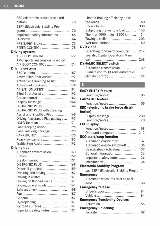
EBD (electronic brake force distri-bution) ............................................. 73ESP® (Electronic Stability Pro-gram) ............................................... 70Important safety information ........... 65Overview .......................................... 64PRE-SAFE® Brake ............................. 73STEER CONTROL ............................. 75
Driving systemAIR BODY CONTROL ...................... 172AMG sports suspension based onAIR BODY CONTROL ...................... 174
Driving systems360°camera .................................. 187Active Blind Spot Assist ................. 197Active Lane Keeping Assist ............ 200Active Parking Assist ..................... 178ATTENTION ASSIST ........................ 191Blind Spot Assist ............................ 193Cruise control ................................ 162Display message ............................ 244DISTRONIC PLUS ........................... 164DISTRONIC PLUS with SteeringAssist and Stop&Go Pilot ............... 169Driving Assistance Plus package ... 197HOLD function ............................... 171Lane Keeping Assist ...................... 195Lane Tracking package .................. 193PARKTRONIC ................................. 175Rear view camera .......................... 182Traffic Sign Assist .......................... 192
Driving tipsAutomatic transmission ................. 143Brakes ........................................... 159Break-in period .............................. 131DISTRONIC PLUS ........................... 169Downhill gradient ........................... 159Drinking and driving ....................... 157Driving in winter ............................. 161Driving on flooded roads ................ 161Driving on wet roads ...................... 161Exhaust check ............................... 158Fuel ................................................ 157General .......................................... 157Hydroplaning ................................. 161Icy road surfaces ........................... 161Important safety notes .................. 131
Limited braking efficiency on sal-ted roads ....................................... 160Snow chains .................................. 338Subjecting brakes to a load ........... 160The first 1000 miles (1500 km) ..... 131Towing a trailer .............................. 203Wet road surface ........................... 160
DVD videoOperating (on-board computer) ..... 217see also Digital Operator's Man-ual .................................................. 268
DYNAMIC SELECT switchAutomatic transmission ................. 139Climate control (3-zone automaticclimate control) ............................. 124
EEASY-ENTRY feature
Function/notes ............................. 105EASY-EXIT feature
Function/notes ............................. 105EBD (electronic brake force distri-bution)
Display message ............................ 230Function/notes ................................ 73
ECO displayFunction/notes ............................. 158On-board computer ....................... 213
ECO start/stop functionAutomatic engine start .................. 137Automatic engine switch-off .......... 136Deactivating/activating ................. 137General information ....................... 136Important safety notes .................. 136Introduction ................................... 136
Electronic Stability Programsee ESP® (Electronic Stability Program)
EmergencyAutomaticmeasures after an acci-dent ................................................. 58
Emergency releaseDriver's door .................................... 84Vehicle ............................................. 84
Emergency Tensioning DevicesActivation ......................................... 55
Emergency unlockingTailgate ............................................ 89
10 Index

Emissions controlService and warranty information .... 28
EngineCheck Engine warning lamp ........... 263Display message ............................ 240ECO start/stop function ................ 136Engine number ............................... 364Irregular running ............................ 138Jump-starting ................................. 328Starting (important safety notes) ... 133Starting problems .......................... 138Starting the engine with theSmartKey ....................................... 134Starting via smartphone ................ 134Starting with the Start/Stop but-ton ................................................. 134Switching off .................................. 155Tow-starting (vehicle) ..................... 333
Engine electronicsProblem (malfunction) ................... 138
Engine oilAdding ........................................... 308Additives ........................................ 368Checking the oil level ..................... 307Checking the oil level using thedipstick .......................................... 308Display message ............................ 242Filling capacity ............................... 368General notes ................................ 367Notes about oil grades ................... 367Notes on oil level/consumption .... 307Temperature (on-board computer,Mercedes-AMG vehicles) ............... 224
Entering an addresssee also Digital Operator's Man-ual .................................................. 268
ESP® (Electronic Stability Pro-gram)
AMG menu (on-board computer) ... 225Characteristics ................................. 70Crosswind Assist ............................. 73Deactivating/activating (buttonin Mercedes-AMG vehicles) ............. 71Deactivating/activating (notes,except Mercedes-AMG vehicles) ...... 70Deactivating/activating (on-board computer, exceptMercedes-AMG vehicles) ............... 220
Display message ............................ 228Function/notes ................................ 70General notes .................................. 70Important safety information ........... 70Trailer stabilization ........................... 73Warning lamp ................................. 259
ETS/4ETS (Electronic Traction Sys-tem) ...................................................... 70Exhaust
see Exhaust pipeExhaust check ................................... 158Exhaust pipe
Cleaning ......................................... 316Exterior lighting
Cleaning ......................................... 315Setting options .............................. 111see Lights
Exterior mirrorsAdjusting ....................................... 107Dipping (automatic) ....................... 108Folding in/out (automatically) ....... 107Folding in/out (electrically) ........... 107Out of position (troubleshooting) ... 108Setting ........................................... 107Storing settings (memory func-tion) ............................................... 109Storing the parking position .......... 108
Eyeglasses compartment ................. 279
FFavorites
Overview ........................................ 271Features ............................................. 290Filler cap
see RefuelingFlat tire
Changing a wheel/mounting thespare wheel ................................... 356MOExtended tires .......................... 321Preparing the vehicle ..................... 321TIREFIT kit ...................................... 322
Floormats ........................................... 305Frequencies
Mobile phone ................................. 362Two-way radio ................................ 362
Front wheel archRemoving/installing the cover ....... 117
Index 11
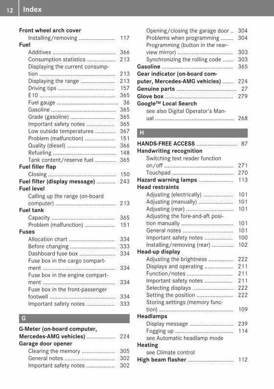
Front wheel arch coverInstalling/removing ....................... 117
FuelAdditives ........................................ 366Consumption statistics .................. 213Displaying the current consump-tion ................................................ 213Displaying the range ...................... 213Driving tips .................................... 157E10 ................................................ 365Fuel gauge ....................................... 36Gasoline ......................................... 365Grade (gasoline) ............................ 365Important safety notes .................. 365Low outside temperatures ............. 367Problem (malfunction) ................... 151Quality (diesel) ............................... 366Refueling ........................................ 148Tank content/reserve fuel ............. 365
Fuel filler flapClosing ........................................... 150
Fuel filter (display message) ............ 243Fuel level
Calling up the range (on-boardcomputer) ...................................... 213
Fuel tankCapacity ........................................ 365Problem (malfunction) ................... 151
FusesAllocation chart ............................. 334Before changing ............................. 333Dashboard fuse box ....................... 334Fuse box in the cargo compart-ment .............................................. 334Fuse box in the engine compart-ment .............................................. 334Fuse box in the front-passengerfootwell .......................................... 334Important safety notes .................. 333
GG-Meter (on-board computer,Mercedes-AMG vehicles) .................. 224Garage door opener
Clearing the memory ..................... 305General notes ................................ 302Important safety notes .................. 302
Opening/closing the garage door .. 304Problems when programming ........ 304Programming (button in the rear-view mirror) ................................... 303Synchronizing the rolling code ....... 303
Gasoline ............................................. 365Gear indicator (on-board com-puter, Mercedes-AMG vehicles) ....... 224Genuine parts ...................................... 27Glove box ........................................... 279Google™ Local Search
see also Digital Operator's Man-ual .................................................. 268
HHANDS-FREE ACCESS .......................... 87Handwriting recognition
Switching text reader functionon/off ............................................ 271Touchpad ....................................... 270
Hazard warning lamps ...................... 113Head restraints
Adjusting (electrically) ................... 101Adjusting (manually) ...................... 101Adjusting (rear) .............................. 101Adjusting the fore-and-aft posi-tion manually ................................. 101General notes ................................ 101Important safety notes .................. 100Installing/removing (rear) .............. 102
Head-up displayAdjusting the brightness ................ 222Displays and operating .................. 211Function/notes ............................. 211Important safety notes .................. 211Selecting displays .......................... 222Setting the position ....................... 222Storing settings (memory func-tion) ............................................... 109
HeadlampsDisplay message ............................ 239Fogging up ..................................... 114see Automatic headlamp mode
Heatingsee Climate control
High beam flasher ............................. 112
12 Index

High-beam headlampsAdaptive Highbeam Assist ............. 113Display message ............................ 239Replacing bulbs ............................. 117Switching on/off ........................... 112
Hill start assist .................................. 136HOLD function
Activating ....................................... 172Activation conditions ..................... 172Deactivating ................................... 172Display message ............................ 247Function/notes ............................. 171General notes ................................ 171
Home addresssee also Digital Operator's Man-ual .................................................. 268
HoodClosing ........................................... 307Display message ............................ 254Important safety notes .................. 306Opening ......................................... 306
Horn ...................................................... 35HUD
see Head-up displayHydroplaning ..................................... 161
IIgnition lock
see Key positionsImmobilizer .......................................... 76Indicator and warning lamps
COLLISION PREVENTION ASSISTPLUS .............................................. 265
Indicator lampssee Warning and indicator lamps
Indicatorssee Turn signals
Insect protection on the radiator .... 307Instrument cluster
Overview .......................................... 36Warning and indicator lamps ........... 36
Instrument cluster lighting .............. 208Interior lighting
Automatic control .......................... 115Control ........................................... 115Overview ........................................ 115Reading lamp ................................. 115
iPod®see also Digital Operator's Man-ual .................................................. 268
JJack
Using ............................................. 357Jump starting (engine) ...................... 328
KKey positions
SmartKey ....................................... 132Start/Stop button .......................... 133
KEYLESS-GOActivating ......................................... 78Convenience closing feature ............ 92Deactivation ..................................... 78Locking ............................................ 78Removing the Start/Stop button ... 133Start function ................................... 79Unlocking ......................................... 78
KickdownDriving tips .................................... 144Manual gearshifting ....................... 147
Knee bag .............................................. 50
LLamps
see Warning and indicator lampsLane Keeping Assist
Activating/deactivating ................. 196Activating/deactivating (on-board computer) ............................ 221Display message ............................ 245Function/information .................... 195see Active Lane Keeping Assist
Lane Tracking package ..................... 193Lap time (RACETIMER) ...................... 225LATCH-type (ISOFIX) child seatanchors ................................................ 61Level control
Display message ............................ 245see AIR BODY CONTROL
License plate lamp (display mes-sage) ................................................... 239
Index 13

Light function, activeDisplay message ............................ 239
Light switchOperation ....................................... 111
LightsAdaptive Highbeam Assist ............. 113Automatic headlamp mode ............ 111Cornering light function ................. 113Fogged up headlamps .................... 114General notes ................................ 111Hazard warning lamps ................... 113High beam flasher .......................... 112High-beam headlamps ................... 112Light switch ................................... 111Low-beam headlamps .................... 112Parking lamps ................................ 112Rear fog lamp ................................ 112Setting exterior lighting ................. 111Standing lamps .............................. 112Switching the daytime runninglamps on/off (on-board com-puter) ............................................. 223Turn signals ................................... 112see Interior lighting
Loading guidelines ............................ 278Locking
see Central lockingLocking (doors)
Automatic ........................................ 84Emergency locking ........................... 84From inside (central locking but-ton) .................................................. 83
Locking centrallysee Central locking
Low-beam headlampsDisplay message ............................ 239Replacing bulbs ............................. 116Switching on/off ........................... 112
Lumbar supportAdjusting the 4-way lumbar sup-port ................................................ 102
MM+S tires ............................................ 338Malfunction message
see Display messages
Matte finish (cleaning instruc-tions) .................................................. 314mbrace
Call priority .................................... 298Display message ............................ 233Downloading destinations(COMAND) ..................................... 299Downloading routes ....................... 301Emergency call .............................. 296General notes ................................ 295Geo fencing ................................... 302Info call button .............................. 298Locating a stolen vehicle ............... 300Remote fault diagnosis .................. 300Remote vehicle locking .................. 300Roadside assistance button ........... 297Search & Send ............................... 299Self-test ......................................... 296Speed alert .................................... 301System .......................................... 295Triggering the vehicle alarm ........... 302Vehicle remote unlocking .............. 300
Mechanical keyFunction/notes ................................ 79General notes .................................. 79Inserting .......................................... 79Locking vehicle ................................ 84Removing ......................................... 79Unlocking the driver's door .............. 84
Media Interfacesee Digital Operator's Manual
Memory card (audio) ......................... 217Memory function
Seats, steering wheel, exteriormirrors ........................................... 109
Mercedes-Benz Intelligent Drive360°camera .................................. 187Active Blind Spot Assist ................. 197Active Lane Keeping Assist ............ 200Active Parking Assist ..................... 178ATTENTION ASSIST ........................ 191Blind Spot Assist ............................ 193DISTRONIC PLUS ........................... 164DISTRONIC PLUS with SteeringAssist and Stop&Go Pilot ............... 169General notes ................................ 162Lane Keeping Assist ...................... 195PARKTRONIC ................................. 175
14 Index
PRE-SAFE® (anticipatory occu-pant protection) ............................... 57PRE-SAFE® PLUS (anticipatoryoccupant protection PLUS) .............. 58Rear view camera .......................... 182Traffic Sign Assist .......................... 192
Message memory (on-board com-puter) .................................................. 227Messages
see Display messagessee Warning and indicator lamps
Mirror turn signalCleaning ......................................... 315
Mirrorssee Exterior mirrorssee Vanity mirror (in the sun visor)
Mobile phoneConnecting (Bluetooth® inter-face) .............................................. 275Connecting another mobilephone ............................................ 276Frequencies ................................... 362Installation ..................................... 362Menu (on-board computer) ............ 218Transmission output (maximum) .... 362
Modifying the programming(SmartKey) ........................................... 79MOExtended tires .............................. 321Mounting wheels
Lowering the vehicle ...................... 360Mounting a new wheel ................... 359Preparing the vehicle ..................... 357Raising the vehicle ......................... 357Removing a wheel .......................... 359Securing the vehicle against roll-ing away ........................................ 357
MP3Operation ....................................... 217see also Digital Operator's Man-ual .................................................. 268
Multifunction displayFunction/notes ............................. 210
Multifunction steering wheelOperating the on-board computer .. 209Overview .......................................... 37
Multimedia systemSwitching on and off ...................... 269
Music filessee also Digital Operator's Man-ual .................................................. 268
NNavigation
Displaying (on-board computer) ..... 214Menu (on-board computer) ............ 214see also Digital Operator's Man-ual .................................................. 268
Notes on breaking-in a new vehi-cle ....................................................... 131
OOccupant Classification System(OCS)
Conditions ....................................... 51Faults ............................................... 54Operation ......................................... 51System self-test ............................... 53
Occupant safetyAir bags ........................................... 48Automaticmeasures after an acci-dent ................................................. 58Children in the vehicle ..................... 59Important safety notes .................... 43Introduction to the restraint sys-tem .................................................. 43Occupant Classification System(OCS) ............................................... 51PASSENGER AIR BAG indicatorlamps ............................................... 44Pets in the vehicle ........................... 64PRE-SAFE® (anticipatory occu-pant protection) ............................... 57PRE-SAFE® PLUS (anticipatoryoccupant protection PLUS) .............. 58Restraint system warning lamp ........ 44Seat belt .......................................... 44
OCSConditions ....................................... 51Faults ............................................... 54Operation ......................................... 51System self-test ............................... 53
Odometer ........................................... 212
Index 15

Oilsee Engine oil
On-board computerAMG menu ..................................... 224Assistance graphic menu ............... 219Assistance menu ........................... 220Display messages .......................... 227Displaying a service message ........ 310Displays and operation .................. 208DISTRONIC PLUS ........................... 168Factory settings ............................. 223G-Meter ......................................... 224Head-up display ............................. 211Head-up display menu ................... 222Important safety notes .................. 208Instrument cluster menu ............... 223Lights menu ................................... 223Media menu ................................... 216Menu overview .............................. 212Message memory .......................... 227Navigation menu ............................ 214RACETIMER ................................... 225Radio menu ................................... 216Service menu ................................. 219Settings menu ............................... 220Standard display ............................ 212Telephone menu ............................ 218Trip menu ...................................... 212Video DVD operation ..................... 217
Opening and closing the side trimpanels ................................................. 118Operating safety
Declaration of conformity ................ 30Important safety notes .................... 30
Operating systemsee On-board computer
OperationDigital Operator's Manual ................ 26
Operator's ManualOverview .......................................... 28Vehicle equipment ........................... 28
Outside temperature display ........... 209Overhead control panel ...................... 41Override feature
Rear side windows ........................... 64
PPaddle shifters
see Steering wheel paddle shiftersPaint code number ............................ 363Paintwork (cleaning instructions) ... 313Panic alarm .......................................... 43Panorama roof with power tilt/sliding panel
Important safety notes .................... 93Operating ......................................... 94Problem (malfunction) ..................... 96Rain closing feature ......................... 95Reversing feature ............................. 94
Panoramic roofOperating the roller sunblinds .......... 95
Parcel net ........................................... 286Parking
Important safety notes .................. 154Parking brake ................................ 155Parking position for the exteriormirror on the front-passengerside ................................................ 108Rear view camera .......................... 182Switching off the engine ................ 155see PARKTRONIC
Parking aidsee 360° camerasee Active Parking Assistsee Exterior mirrorssee PARKTRONICsee Rear view camera
Parking AssistDisplay message ............................ 246
Parking brakeApplying automatically ................... 156Applying or releasing manually ...... 156Display message ............................ 230Electric parking brake .................... 155Emergency braking ........................ 157General notes ................................ 155Releasing automatically ................. 156Warning lamp ................................. 262
Parking lampsSwitching on/off ........................... 112
PARKTRONICDeactivating/activating ................. 177Driving system ............................... 175
16 Index
Function/notes ............................. 175Important safety notes .................. 175Problem (malfunction) ................... 178Range of the sensors ..................... 176Warning display ............................. 177
PASSENGER AIR BAGDisplay message ............................ 237Indicator lamps ................................ 44Problems (malfunction) .................. 237
Perfume atomizerOperating ....................................... 128Problem (malfunction) ................... 129Setting the perfume intensity(multimedia system) ...................... 272Vial ................................................ 128
Pets in the vehicle ............................... 64Phone book
see also Digital Operator's Man-ual .................................................. 268
Plastic trim (cleaning instruc-tions) .................................................. 317Power washers .................................. 313Power windows
see Side windowsPRE-SAFE® (anticipatory occupantprotection)
Display message ............................ 234Operation ......................................... 57
PRE-SAFE® BrakeActivating/deactivating ................. 221Display message ............................ 234Function/notes ................................ 73Important safety notes .................... 74Warning lamp ................................. 265
PRE-SAFE® PLUS (anticipatoryoccupant protection PLUS)
Operation ......................................... 58Protection against theft
ATA (Anti-Theft Alarm system) ......... 76Immobilizer ...................................... 76
Protection of the environmentGeneral notes .................................. 27
Pulling awayAutomatic transmission ................. 135General notes ................................ 135Hill start assist ............................... 136Trailer ............................................ 135
QQR code
Mercedes-Benz Guide App ................. 1Rescue card ..................................... 32
Qualified specialist workshop ........... 31Quick access for audio and tele-phone
Changing the station/musictrack .............................................. 271
RRACE TIMER (on-board computer,Mercedes-AMG vehicles) .................. 225Radar sensor system
Display message ............................ 235Radiator cover ................................... 307Radio
Selecting a station ......................... 216Radio mode
see also Digital Operator's Man-ual .................................................. 268
Radio-wave reception/transmis-sion in the vehicle
Declaration of conformity ................ 30Rain closing feature (panoramaroof with power tilt/sliding panel) .... 95Reading lamp ..................................... 115Rear compartment
Setting the air vents ...................... 130Rear fog lamp
Display message ............................ 239Switching on/off ........................... 112
Rear seatAdjusting the angle of the backr-ests ................................................ 283
Rear seat backrestDisplay message ............................ 254
Rear seatsDisplay message ............................ 254
Rear view camera"Reverse parking" function ............ 184Cleaning instructions ..................... 316Coupling up a trailer function ........ 186Display in the multimedia system .. 183General notes ................................ 182
Index 17

Object detection (function/notes) ............................................ 186Switching on/off ........................... 183Wide-angle function ....................... 186
Rear window defrosterProblem (malfunction) ................... 127Switching on/off ........................... 127
Rear window wiperReplacing the wiper blade .............. 121Switching on/off ........................... 120
Rear-view mirrorDipping (automatic) ....................... 108
Recuperation display ........................ 213Reflective safety jacket .................... 319Refrigerant (air-conditioning sys-tem)
Important safety notes .................. 369Refueling
Fuel gauge ....................................... 36Important safety notes .................. 148Refueling process .......................... 149see Fuel
Remote controlGarage door opener ....................... 302Programming (garage dooropener) .......................................... 303
Replacing bulbsBackup lamp .................................. 118High-beam headlamps ................... 117Important safety notes .................. 115Installing/removing the cover(front wheel arch) .......................... 117Low-beam headlamps .................... 116Opening/closing side trim panels .. 118Overview of bulb types .................. 116Replacing front bulbs (vehicleswith halogen headlamps) ............... 116Turn signals (front) ......................... 117
Reporting safety defects .................... 32Rescue card ......................................... 32Reserve (fuel tank)
see FuelReserve fuel
Display message ............................ 242Warning lamp ................................. 263
Restraint systemDisplay message ............................ 235Introduction ..................................... 43
Warning lamp ................................. 262Warning lamp (function) ................... 44
Reversing featurePanorama sliding sunroof ................ 94Roller sunblinds ............................... 95Side windows ................................... 90Tailgate ............................................ 85
Roadside Assistance (breakdown) .... 29Roller sunblind
Operating ......................................... 96Panorama roof with power tilt/sliding panel ..................................... 95Rear side windows ......................... 291Resetting ......................................... 96
Roof carrier ........................................ 289Roof lining and carpets (cleaningguidelines) ......................................... 318Roof load (maximum) ........................ 370Route guidance
see also Digital Operator's Man-ual .................................................. 268
Route guidance active ...................... 214
SSafety
Children in the vehicle ..................... 59see Occupant safetysee Operating safety
SD cardInserting/removing ........................ 276Selecting ........................................ 217
SD memory cardsee also Digital Operator's Man-ual .................................................. 268
Search & Sendsee also Digital Operator's Man-ual .................................................. 268
SeatCorrect driver's seat position ........... 98
Seat beltsAdjusting the driver's and front-passenger seat belt ......................... 47Adjusting the height ......................... 47center rear-compartment seat ......... 47Cleaning ......................................... 318Correct usage .................................. 46Fastening ......................................... 47
18 Index
Important safety guidelines ............. 45Introduction ..................................... 44Releasing ......................................... 47Warning lamp ................................. 256Warning lamp (function) ................... 47
SeatsAdjusting (AMG PerformanceSeat) .............................................. 102Adjusting (electrically) ................... 100Adjusting the 4-way lumbar sup-port ................................................ 102Adjusting the head restraint .......... 100Calling up a stored setting (mem-ory function) .................................. 110Cleaning the cover ......................... 317Folding the backrest (rear com-partment) forwards/back .............. 281Important safety notes .................... 98Seat heating .................................. 102Seat heating problem .................... 104Seat ventilation .............................. 103Seat ventilation problem ................ 104Storing settings (memory func-tion) ............................................... 109
Securing a loadsee Securing cargo
Securing cargo .................................. 284Selector lever
Cleaning ......................................... 317see Automatic transmission
Sensors (cleaning instructions) ....... 315Service menu (on-board com-puter) .................................................. 219Service message
see ASSYST PLUSService products
Brake fluid ..................................... 368Coolant (engine) ............................ 368DEF special additives ..................... 367Engine oil ....................................... 367Fuel ................................................ 364Important safety notes .................. 364Refrigerant (air-conditioning sys-tem) ............................................... 369Washer fluid ................................... 369
Setting the date/time formatsee also Digital Operator's Man-ual .................................................. 268
Setting the languagesee also Digital Operator's Man-ual .................................................. 268
Setting the timesee also Digital Operator's Man-ual .................................................. 268
SettingsFactory (on-board computer) ......... 223On-board computer ....................... 220
SETUP (on-board computer,Mercedes-AMG vehicles) .................. 225Side impact air bag ............................. 50Side marker lamp (display mes-sage) ................................................... 239Side running board
Cleaning ......................................... 315Side windows
Cleaning ......................................... 314Convenience closing feature ............ 91Convenience opening feature .......... 91Important safety information ........... 90Opening/closing .............................. 90Problem (malfunction) ..................... 93Resetting ......................................... 92Reversing feature ............................. 90
SIRIUS servicessee also Digital Operator's Man-ual .................................................. 268
Ski and snowboard bag .................... 280Sliding sunroof
Important safety notes .................... 93Problem (malfunction) ..................... 96see Panorama roof with powertilt/sliding panel
SmartKeyChanging the battery ....................... 80Changing the programming ............. 79Checking the battery ....................... 80Convenience closing feature ............ 92Convenience opening feature .......... 91Display message ............................ 255Door central locking/unlocking ....... 77Important safety notes .................... 77KEYLESS-GO start function .............. 79Loss ................................................. 81Mechanical key ................................ 79Overview .......................................... 77Positions (ignition lock) ................. 132
Index 19

Problem (malfunction) ..................... 81Starting the engine ........................ 134
SmartphoneStarting the engine ........................ 134
SMSsee also Digital Operator's Man-ual .................................................. 268
Snow chains ...................................... 338Socket (12 V)
Cargo compartment ....................... 293Center console .............................. 293General notes ................................ 293Rear compartment ......................... 293
SoundSwitching on/off ........................... 269
Special seat belt retractor .................. 59Specialist workshop ............................ 31Speed, controlling
see Cruise controlSpeedometer
Activating/deactivating the addi-tional speedometer ........................ 223Digital ............................................ 213In the Instrument cluster ................. 36Segments ...................................... 208Selecting the display unit ............... 223
SPORT handling modeDeactivating/activating(Mercedes-AMG vehicles) ................ 71Warning lamp ................................. 261
Standing lampsDisplay message ............................ 239Switching on/off ........................... 112
Start buttonDisplay message ............................ 256
Start/Stop buttonKey positions ................................. 133Starting the engine ........................ 134
Start/stop functionsee ECO start/stop function
Starting (engine) ................................ 133STEER CONTROL .................................. 75Steering
Display message ............................ 254Warning lamps ............................... 267
Steering Assist and Stop&Go Pilot .. 169
Steering Assist and Stop&Go Pilot(DISTRONIC PLUS)
Display message ............................ 248Steering assistant STEER CON-TROL
see STEER CONTROLSteering wheel
Adjusting (electrically) ................... 105Adjusting (manually) ...................... 104Button overview ............................... 37Buttons (on-board computer) ......... 209Cleaning ......................................... 317EASY ENTRY/EXIT feature ............. 105Important safety notes .................. 104Storing settings (memory func-tion) ............................................... 109
Steering wheel heatingProblem (malfunction) ................... 105Switching on/off ........................... 105
Steering wheel paddle shifters ........ 145Stop&Go Pilot and Steering Assist .. 169Stopwatch (RACETIMER) ................... 225Stowage areas ................................... 278Stowage compartments
Armrest (under) ............................. 279Center console .............................. 279Cup holders ................................... 290Door ............................................... 280Eyeglasses compartment ............... 279Glove box ....................................... 279Important safety information ......... 278Map pockets .................................. 280Rear ............................................... 280Stowage net ................................... 280see Stowage areas
Stowage net ....................................... 280Summer tires
In winter ........................................ 338Sun visor ............................................ 291Suspension settings
AIR BODY CONTROL ...................... 173Suspension tuning
AMG sports suspension based onAIR BODY CONTROL ...................... 174SETUP (on-board computer,Mercedes-AMG vehicles) ............... 225
20 Index

SUV(Sport Utility Vehicle) ....................... 30
Switching air-recirculation modeon/off ................................................. 128Switching on media mode
Via the device list .......................... 276
TTachometer ........................................ 209Tail lamps
Display message ............................ 239Tailgate
Display message ............................ 253Emergency unlocking ....................... 89HANDS-FREE ACCESS ..................... 87Important safety notes .................... 84Limiting the opening angle ............... 89Obstruction detection ...................... 85Opening dimensions ...................... 370Opening/closing (automaticallyfrom inside) ...................................... 88Opening/closing (automaticallyfrom outside) ................................... 86Opening/closing (manually fromoutside) ............................................ 85Reversing feature ............................. 85
Tank contentFuel gauge ....................................... 36
Technical dataCapacities ...................................... 364Drawbar load (maximum) ............... 371Information .................................... 362Trailer loads ................................... 371Vehicle data ................................... 370
TelephoneAccepting a call (multifunctionsteering wheel) .............................. 218Authorizing a mobile phone (con-necting) ......................................... 275Connecting a mobile phone (gen-eral information) ............................ 275Display message ............................ 254Introduction ................................... 218Menu (on-board computer) ............ 218Number from the phone book ........ 218Redialing ........................................ 219Rejecting/ending a call ................. 218
see also Digital Operator's Man-ual .................................................. 268Switching between mobilephones ........................................... 276see Mobile phone
TemperatureCoolant (display in the instrumentcluster) .......................................... 209Engine oil (on-board computer,Mercedes-AMG vehicles) ............... 224Outside temperature ...................... 209Setting (climate control) ................ 126Transmission oil (on-board com-puter, Mercedes-AMG vehicles) ..... 224
Timing (RACETIMER) ......................... 225Tire pressure
Calling up (on-board computer) ..... 343Checking manually ........................ 342Display message ............................ 250Maximum ....................................... 342Not reached (TIREFIT) .................... 324Notes ............................................. 341Reached (TIREFIT) .......................... 324Recommended ............................... 339Using the TIREFIT kit ...................... 323
Tire pressure loss warning systemGeneral notes ................................ 342Important safety notes .................. 342Restarting ...................................... 343
Tire pressure monitorChecking the tire pressure elec-tronically ........................................ 345Function/notes ............................. 343General notes ................................ 343Important safety notes .................. 344Radio type approval for the tirepressure monitor ........................... 346Restarting ...................................... 345Warning lamp ................................. 266Warning message .......................... 345
Tire pressure sensorsDisplay message ............................ 251
Tire-change tool kit ........................... 320TIREFIT kit
Important safety notes .................. 322Storage location ............................ 320Tire pressure not reached .............. 324Tire pressure reached .................... 324
Index 21

Using ............................................. 323Tires
Aspect ratio (definition) ................. 355Average weight of the vehicleoccupants (definition) .................... 354Bar (definition) ............................... 354Changing a wheel .......................... 356Characteristics .............................. 354Checking ........................................ 336Curb weight (definition) ................. 355Definition of terms ......................... 354Direction of rotation ...................... 356Display message ............................ 250Distribution of the vehicle occu-pants (definition) ............................ 356DOT (Department of Transporta-tion) (definition) ............................. 354DOT, Tire Identification Number(TIN) ............................................... 353GAWR (Gross Axle Weight Rating)(definition) ..................................... 354GVW (Gross Vehicle Weight) (def-inition) ........................................... 355GVWR (Gross Vehicle Weight Rat-ing) (definition) .............................. 355Important safety notes .................. 336Increased vehicle weight due tooptional equipment (definition) ...... 354Information on driving .................... 336Kilopascal (kPa) (definition) ........... 355Labeling (overview) ........................ 351Load bearing index (definition) ...... 356Load index ..................................... 353Load index (definition) ................... 355Maximum load on a tire (defini-tion) ............................................... 355Maximum loaded vehicle weight(definition) ..................................... 355Maximum permissible tire pres-sure (definition) ............................. 355Maximum tire load ......................... 353Maximum tire load (definition) ....... 355MOExtended tires .......................... 338Optional equipment weight (defi-nition) ............................................ 356PSI (pounds per square inch) (def-inition) ........................................... 355Replacing ....................................... 356
Service life ..................................... 337Sidewall (definition) ....................... 355Snow chains .................................. 338Speed rating (definition) ................ 355Storing ........................................... 357Structure and characteristics(definition) ..................................... 354Summer tires in winter .................. 338Temperature .................................. 350TIN (Tire Identification Number)(definition) ..................................... 356Tire bead (definition) ...................... 355Tire pressure (definition) ................ 355Tire pressures (recommended) ...... 354Tire size (data) ............................... 360Tire size designation, load-bearingcapacity, speed rating .................... 351Tire tread ....................................... 337Tire tread (definition) ..................... 355Total load limit (definition) ............. 356Traction ......................................... 350Traction (definition) ....................... 356Tread wear ..................................... 350Uniform Tire Quality GradingStandards ...................................... 349Uniform Tire Quality GradingStandards (definition) .................... 354Wear indicator (definition) ............. 356Wheel and tire combination ........... 360Wheel rim (definition) .................... 354see Flat tire
Top Tether ............................................ 61Topping up
DEF ................................................ 151Touchpad
Changing the station/musictrack .............................................. 271Character suggestions ................... 270Deleting characters ....................... 270Entering a space ............................ 270Entering characters ....................... 270Gesture control .............................. 270Handwriting recognition ................ 270Operating the touchpad ................. 270Overview ........................................ 270Quick access for Audio .................. 271Switching ....................................... 270Switching input line ....................... 270
22 Index

Tow-startingEmergency engine starting ............ 333Important safety notes .................. 330
Towing a trailerAxle load, permissible .................... 371Cleaning the trailer tow hitch ......... 316Coupling up a trailer ...................... 204Decoupling a trailer ....................... 206Driving tips .................................... 203ESP® (Electronic Stability Pro-gram) ............................................... 73Important safety notes .................. 202Installing the ball coupling ............. 204Lights display message .................. 239Power supply ................................. 206Pulling away with a trailer .............. 135Removing the ball coupling ............ 206Trailer loads ................................... 371
Towing awayImportant safety guidelines ........... 330Installing the towing eye ................ 331Notes for 4MATIC vehicles ............ 333Removing the towing eye ............... 332Transporting the vehicle ................ 332With both axles on the ground ....... 332
Towing eye ......................................... 320Traffic reports
see also Digital Operator's Man-ual .................................................. 268
Traffic Sign AssistDisplay message ............................ 247Function/notes ............................. 192Important safety notes .................. 193Instrument cluster display ............. 193
Trailer couplingsee Towing a trailer
Trailer loads and drawbar nose-weights ............................................... 206Trailer towing
Active Lane Keeping Assist ............ 202Blind Spot Assist ............................ 195Permissible trailer loads anddrawbar noseweights ..................... 206
Transfer case ..................................... 148Transmission
Display message ............................ 253see Automatic transmission
Transmission oilTemperature (on-board computer,Mercedes-AMG vehicles) ............... 224
Transmission position display ......... 142Transporting the vehicle .................. 332Trim pieces (cleaning instruc-tions) .................................................. 317Trip computer (on-board com-puter) .................................................. 213Trip odometer
Calling up ....................................... 212Resetting (on-board computer) ...... 214
Trunksee Cargo compartment
Trunk load (maximum) ...................... 370Turn signals
Display message ............................ 239Replacing bulbs (front) ................... 117Switching on/off ........................... 112
Two-way radioFrequencies ................................... 362Installation ..................................... 362Transmission output (maximum) .... 362
Type identification platesee Vehicle identification plate
UUnlocking
Emergency unlocking ....................... 84From inside the vehicle (centralunlocking button) ............................. 83
USB devicesConnecting to the Media Inter-face ............................................... 276
VVanity mirror (in the sun visor) ........ 291Vehicle
Correct use ...................................... 31Data acquisition ............................... 32Display message ............................ 252Electronics ..................................... 362Equipment ....................................... 28Individual settings .......................... 220Limited Warranty ............................. 32Loading .......................................... 346
Index 23

Locking (in an emergency) ............... 84Locking (SmartKey) .......................... 77Lowering ........................................ 360Maintenance .................................... 29Operating safety .............................. 30Operation outside the USA/Canada ............................................ 29Parking .......................................... 154Parking for a long period ................ 157Pulling away ................................... 135Raising ........................................... 357Reporting problems ......................... 31Securing from rolling away ............ 357Technical data ............................... 362Towing away .................................. 330Transporting .................................. 332Unlocking (in an emergency) ........... 84Unlocking (SmartKey) ...................... 77Vehicle data ................................... 370
Vehicle dataDimensions .................................... 370
Vehicle emergency locking ................ 84Vehicle identification number
see VINVehicle identification plate .............. 363Vehicle level
AIR BODY CONTROL ...................... 173Display message ............................ 244
VideoOperating the DVD ......................... 217see also Digital Operator's Man-ual .................................................. 268
VINSeat ............................................... 364Type plate ...................................... 363
WWarning and indicator lamps
ABS ................................................ 259Air bags ......................................... 262Brakes ........................................... 258Coolant .......................................... 263Distance warning ........................... 265Engine diagnostics ......................... 263ESP® .............................................. 259ESP® OFF ....................................... 261Fuel tank ........................................ 263
General notes ................................ 256Overview .......................................... 36Parking brake ................................ 262PASSENGER AIR BAG ...................... 44Reserve fuel ................................... 263Restraint system ............................ 262Seat belt ........................................ 256SPORT handling mode ................... 261Steering ......................................... 267Tire pressure monitor .................... 266
Warranty .............................................. 28Washer fluid
Display message ............................ 254Weather display (COMAND)
see also Digital Operator's Man-ual .................................................. 268
Wheel and tire combinationsTires ............................................... 360
Wheel bolt tightening torque ........... 360Wheel chock ...................................... 357Wheels
Changing a wheel .......................... 356Checking ........................................ 336Cleaning ......................................... 314Important safety notes .................. 336Information on driving .................... 336Interchanging/changing ................ 356Mounting a new wheel ................... 359Mounting a wheel .......................... 357Removing a wheel .......................... 359Snow chains .................................. 338Storing ........................................... 357Tightening torque ........................... 360Wheel size/tire size ....................... 360
Window curtain air bagDisplay message ............................ 236Operation ......................................... 50
Windowssee Side windows
WindshieldDefrosting ...................................... 126
Windshield washer fluidsee Windshield washer system
Windshield washer systemAdding washer fluid ....................... 310Important safety notes .................. 369
Windshield wipersProblem (malfunction) ................... 122
24 Index
Rear window wiper ........................ 120Replacing the wiper blades ............ 120Switching on/off ........................... 119
Winter drivingImportant safety notes .................. 338Slippery road surfaces ................... 161Snow chains .................................. 338
Winter operationRadiator cover ............................... 307Summer tires ................................. 338
Winter tiresM+S tires ....................................... 338
Wiper bladesCleaning ......................................... 315Important safety notes .................. 120Replacing ....................................... 120Replacing (rear window) ................ 121Replacing (windshield) ................... 120
Without changing gearsDisplay message ............................ 253
Wooden trim (cleaning instruc-tions) .................................................. 317Workshop
see Qualified specialist workshop
Index 25

Introduction
The printed Operator's Manual provides infor-mation about the safe operation of your vehicle.The Digital Operator's Manual provides compre-hensive and specifically adapted information onyour vehicle's equipment and multimedia sys-tem. You can call up the Digital Operator's Man-ual via the multimedia system.
i You will not incur any costs when calling upthe Digital Operator's Manual. The DigitalOperator's Manual works without connectingto the Internet.
There are three ways to access the topics of theDigital Operator's Manual:RVisual searchThe visual search allows you to explore yourvehicle "virtually". Starting from either thevehicle exterior view or interior view, you canaccess many of the different topics coveredby the Digital Operator's Manual. To accessthe vehicle interior section, select the "Vehi-cle interior" view.RKeyword searchThe keyword search allows you to search for akeyword by entering characters.RContentsYou can select individual sections in the con-tents.
i The Digital Operator's Manual is deactiva-ted for safety reasons while driving.
Operation
Calling up the Digital Operator's Man-ualX Press theØ button on the center console.The overview relating to the vehicle appears.
X Select the "Operator's Manual" menu item byturning3 or pressing7 the controller.
X Confirm7 the message about the warningand safety notes.The basic menu for the Digital Operator'sManual appears.
Operating the Digital Operator's Man-ual
General notesPlease observe the information about the oper-ation of the controller (Y page 269).
Content pagesThe content pages can be accessed bymeans ofa visual search, a keyword search or using thecontents.
X To scroll forward/back: turn3 the con-troller.
X To display in full-screen or animation: slide8 the controller to the left:.
X To select information text or save book-marks: slide9 the controller to theright;.
X To select a link: slide6 the controllerdownwards=.
X To exit a content page: select the%symbol?.
X To call up the basic menu of the DigitalOperator's Manual: selectÞ symbolA.
X To switch functions to the multimediasystem using the buttons on the centerconsole: press the$,%,Õ orØbutton.The selected menu appears. The Digital Oper-ator's Manual remains open in the back-ground.
26 Digital Operator's Manual

Protecting the environment
General notes
H Environmental noteDaimler's declared policy is one of compre-hensive environmental protection.The objectives are for the natural resourcesthat form the basis of our existence on thisplanet to be used sparingly and in a mannerthat takes the requirements of both natureand humanity into account.You too can help to protect the environmentby operating your vehicle in an environmen-tally responsible manner.Fuel consumption and the rate of engine,transmission, brake and tire wear are affectedby these factors:Roperating conditions of your vehicleRyour personal driving styleYou can influence both factors. You shouldbear the following in mind:Operating conditions:Ravoid short trips as these increase fuel con-sumption.Ralways make sure that the tire pressuresare correct.Rdo not carry any unnecessary weight.Rremove roof racks once you no longer needthem.Ra regularly serviced vehicle will contributeto environmental protection. You shouldtherefore adhere to the service intervals.Ralways have service work carried out at aqualified specialist workshop.
Personal driving style:Rdo not depress the accelerator pedal whenstarting the engine.Rdo notwarmup the enginewhen the vehicleis stationary.Rdrive carefully and maintain a safe distancefrom the vehicle in front.Ravoid frequent, sudden acceleration andbraking.
Rchange gear in good time and use each gearonly up toÔ of its maximum engine speed.Rswitch off the engine in stationary traffic.Rkeep an eye on the vehicle's fuel consump-tion.
Environmental concerns and recom-mendationsWherever the Operator'sManual requires you todispose ofmaterials, first try to regenerate or re-use them. Observe the relevant environmentalrules and regulations when disposing of materi-als. In this way you will help to protect the envi-ronment.
Genuine Mercedes-Benz parts
H Environmental noteDaimler AG also supplies reconditionedmajorassemblies and parts which are of the samequality as new parts. They are covered by thesame Limited Warranty entitlements as newparts.
! Air bags and Emergency Tensioning Devi-ces, as well as control units and sensors forthese restraint systems, may be installed inthe following areas of your vehicle:RdoorsRdoor pillarsRdoor sillsRseatsRcockpitRinstrument clusterRcenter consoleDo not install accessories such as audio sys-tems in these areas. Do not carry out repairsor welding. You could impair the operatingefficiency of the restraint systems.Have aftermarket accessories installed at aqualified specialist workshop.
You could jeopardize the operating safety ofyour vehicle if you use parts, tires and wheels aswell as accessories relevant to safety whichhave not been approved byMercedes-Benz. Thiscould lead to malfunctions in safety-relevant
Genuine Mercedes-Benz parts 27
Introductio
n
Z

systems, e.g. the brake system. Use only genu-ine Mercedes-Benz parts or parts of equal qual-ity. Only use tires, wheels and accessories thathave been specifically approved for your vehi-cle.Genuine Mercedes-Benz parts are subject tostrict quality control. Every part has been spe-cifically developed, manufactured or selectedfor and adapted to Mercedes-Benz vehicles.Therefore, only genuine Mercedes-Benz partsshould be used.More than 300,000 different genuineMercedes-Benz parts are available forMercedes-Benz models.All authorized Mercedes-Benz Centers maintaina supply of genuine Mercedes-Benz parts fornecessary service and repair work. In addition,strategically located parts delivery centers pro-vide quick and reliable parts service.Always specify the vehicle identification number(VIN) when ordering genuine Mercedes-Benzparts (Y page 363).
Operator's Manual
Vehicle equipmenti ThisOperator'sManual describes allmodelsand all standard and optional equipment ofyour vehicle available at the time of publica-tion of the Operator's Manual. Country-spe-cific differences are possible. Bear in mindthat your vehicle may not feature all functionsdescribed here. This also applies to safety-relevant systems and functions. The equip-ment in your vehiclemay therefore differ fromthat shown in the descriptions and illustra-tions.
The original purchase agreement lists all sys-tems installed in your vehicle.Should you have any questions concerningequipment and operation, please consult anauthorized Mercedes-Benz Center.The Operator's Manual and Maintenance Book-let are important documents and should be keptin the vehicle.
Service and vehicle operation
WarrantyThe Limited Warranty for your vehicle applies inaccordance with the warranty terms and condi-tions in the Service and Warranty Informationbooklet.Your authorized Mercedes-Benz Center willreplace and repair all factory-installed parts inaccordance with the following warranty termsand conditions:RNew Vehicle Limited WarrantyREmission System WarrantyREmission Performance WarrantyRCalifornia, Connecticut, Maine, Massachu-setts, New York, Pennsylvania, Rhode Islandand Vermont Emission Control System War-rantyRState warranty enforcement laws (lemonlaws)
Replacement parts and accessories are coveredby the Mercedes-Benz Parts and Accessorieswarranties. These are available at any author-ized Mercedes-Benz Center.
i Should you lose your Service and WarrantyInformation booklet, have an authorizedMercedes-Benz Center arrange for a replace-ment. The new Service and Warranty Infor-mation booklet will be posted to you.
Information for customers in Califor-niaUnder California law you may be entitled to areplacement of your vehicle or a refund of thepurchase price or lease price, if after a reason-able number of repair attempts Mercedes-BenzUSA, LLC and/or its authorized repair or servicefacilities fail to fix one or more substantialdefects or malfunctions in the vehicle that arecovered by its express warranty.During the period of 18 months from originaldelivery of the vehicle or the accumulation of18,000 miles (approximately 29,000 km) on theodometer of the vehicle, whichever occurs first,a reasonable number of repair attempts is pre-sumed for a retail buyer or lessee if one or moreof the following occurs:(1) the substantial defect or malfunction can
result in death or serious injuries for the
28 Service and vehicle operationIntroductio
n

vehicle occupants while driving and thisdefect has already been repaired at leasttwice and Mercedes-Benz, LLC has beeninformed in writing of the necessity of arepair.
(2) the defect or malfunction, though less seri-ous than (1) above, has already beenrepaired at least four times and Mercedes-Benz has been informed in writing of thenecessity of a repair.
(3) the vehicle cannot be used for longer than30 calendar days because of repair workresulting from this or other substantialdefects or malfunctions.
Please send your written notice to:Mercedes-Benz USA, LLCCustomer Assistance Center3 Mercedes DriveMontvale, NJ 07645-0350
MaintenanceAlways bring the Maintenance Booklet with youwhen taking the vehicle to an authorizedMercedes-Benz Center. Your customer serviceadvisor will enter every service into your Main-tenance Booklet on your behalf.
Roadside AssistanceThe Mercedes-Benz Roadside Assistance Pro-gram offers technical help in the event of abreakdown. Calls to the toll-free Roadside Assis-tance Hotline are answered by our agents 24hours a day, 365 days a year.1-800-FOR-MERCedes(1-800-367-6372)(USA)1-800-387-0100(Canada)For additional information, refer to theMercedes-Benz Roadside Assistance Programbrochure (USA) or the "Roadside Assistance"section in the Service and Warranty Booklet(Canada). You will find both in the vehicle docu-ment wallet.
Change of address or change of own-ershipIn the event of a change of address, please sendus the "Notification of Address Change" in the
Service and Warranty Booklet or simply call theMercedes-Benz Customer Assistance Center(USA) at the hotline number1-800-FOR-MERCedes (1-800-367-6372) orCustomer Service Center (Canada) at1-800-387-0100. This will assist us in contact-ing you in a timelymanner should the need arise.If you sell your Mercedes, please leave all liter-ature in the vehicle so that it is available to thenext owner.If you have purchased a used car, please send usthe "Notification of Used Car Purchase" in theService and Warranty Booklet or simply call theMercedes-Benz Customer Assistance Center(USA) at the hotline number1-800-FOR-MERCedes (1-800-367-6372) orCustomer Service (Canada) at 1-800-387-0100.
Vehicle operation outside the USAand CanadaWhen you are abroad with your vehicle, observethe following points:RService facilities or replacement parts maynot be readily available.RLead-free fuel for vehicles with a catalyticconverter may not be available. Leaded fuelcan cause damage to the catalytic converter.RThe fuel may have a considerably loweroctane number. Unsuitable fuel can causeengine damage.
Some Mercedes-Benz models are available fordelivery in Europe through our European Deliv-ery Program. For details, consult an authorizedMercedes-Benz Center or write to one of thefollowing addresses.In the USAMercedes-Benz USA, LLCEuropean Delivery DepartmentOne Mercedes DriveMontvale, NJ 07645-0350In CanadaMercedes-Benz Canada, Inc.European Delivery Department98 Vanderhoof AvenueToronto, Ontario M4G 4C9
Service and vehicle operation 29
Introductio
n
Z
Sports Utility Vehicle
G WARNINGDue to the high center of gravity, the vehiclemay start to skid and roll over in the event ofan abrupt steering maneuver and/or whenthe vehicle's speed is not adapted to the roadconditions. There is a risk of an accident.Always adapt your speed and driving style tothe vehicle's driving characteristics and to theprevailing road and weather conditions.
Utility vehicles have a significantly higher roll-over rate than other types of vehicles.Failure to operate this vehicle safely may resultin an accident, rollover of the vehicle, and severeor fatal injury.In a rollover crash, an unbelted person is signif-icantly more likely to die than a person wearinga seat belt.You and all vehicle occupants should alwayswear your seat belts.
Operating safety
Important safety notes
G WARNINGIf you do not have the prescribed service/maintenance work or any required repairscarried out, this can result in malfunctions orsystem failures. There is a risk of an accident.Always have the prescribed service/mainte-nance work as well as any required repairscarried out at a qualified specialist workshop.
G WARNINGFlammable material such as leaves, grass ortwigsmay ignite if they come into contactwithhot parts of the exhaust system. There is a riskof fire.When driving off road or on unpaved roads,check the vehicle's underside regularly. Inparticular, remove parts of plants or otherflammable materials which have becometrapped. In the case of damage, contact aqualified specialist workshop.
G WARNINGModifications to electronic components, theirsoftware as well as wiring can impair theirfunction and/or the function of other net-worked components. In particular, systemsrelevant to safety could also be affected. As aresult, these may no longer function as inten-ded and/or jeopardize the operating safety ofthe vehicle. There is an increased risk of anaccident and injury.Never tamper with the wiring as well as elec-tronic components or their software. Youshould have all work to electrical and elec-tronic equipment carried out at a qualifiedspecialist workshop.
! There is a risk of damage to the vehicle if:Rthe vehicle becomes stuck, e.g. on a highcurb or an unpaved roadRyou drive too fast over an obstacle, e.g. acurb, a speed bump or a pothole in the roadRa heavy object strikes the underbody orparts of the chassis
In situations like this, the body, the under-body, chassis parts, wheels or tires could bedamaged without the damage being visible.Components damaged in this way can unex-pectedly fail or, in the case of an accident, nolonger withstand the loads they are designedto.If the underbody paneling is damaged, com-bustible materials such as leaves, grass ortwigs can gather between the underbody andthe underbody paneling. If these materialscome in contact with hot parts of the exhaustsystem, they can catch fire.In such situations, have the vehicle checkedand repaired immediately at a qualified spe-cialist workshop. If on continuing your jour-ney you notice that driving safety is impaired,pull over and stop the vehicle immediately,paying attention to road and traffic condi-tions. In such cases, consult a qualified spe-cialist workshop.
Declaration of conformity forwirelessvehicle componentsUSA: "The wireless devices of this vehicle com-ply with Part 15 of the FCC Rules. Operation is
30 Operating safetyIntroductio
n

subject to the two following two conditions: 1)These devices may not cause harmful interfer-ence, and 2) These devices must accept anyinterference received, including interferencethat may cause undesired operation. Changesor modifications not expressly approved by theparty responsible for compliance could void theuser’s authority to operate the equipment."Canada: "The wireless devices of this vehiclecomply with Industry Canada license-exemptRSS standard(s). Operation is subject to the fol-lowing two conditions: (1) These devices maynot cause interference, and (2) These devicesmust accept any interference, including inter-ference that may cause undesired operation ofthe device."
Diagnostics connectionThe diagnostics connection is only intended forthe connection of diagnostic equipment at aqualified specialist workshop.
G WARNINGIf you connect equipment to a diagnosticsconnection in the vehicle, it may affect theoperation of vehicle systems. As a result, theoperating safety of the vehicle could be affec-ted. There is a risk of an accident.Only connect equipment to a diagnostics con-nection in the vehicle, which is approved foryour vehicle by Mercedes-Benz.
G WARNINGObjects in the driver's footwell can restrict thepedal travel or obstruct a depressed pedal.The operating and road safety of the vehicle isjeopardized. There is a risk of an accident.Make sure that all objects in the vehicle arestowed correctly, and that they cannot enterthe driver's footwell. Install the floormatssecurely and as specified in order to ensuresufficient clearance for the pedals. Do not useloose floormats and do not place floormats ontop of one another.
! If the engine is switched off and equipmenton the diagnostics connection is used, thestarter battery may discharge.
Connecting equipment to the diagnostics con-nection can lead to emissions monitoring infor-mation being reset, for example. This may leadto the vehicle failing tomeet the requirements ofthe next emissions test during the main inspec-tion.
Qualified specialist workshopAn authorized Mercedes-Benz Center is a quali-fied specialist workshop. It has the necessaryspecialist knowledge, tools and qualifications tocorrectly carry out the work required on yourvehicle. This is especially the case for work rel-evant to safety.Observe the notes in the Maintenance Booklet.Always have the following work carried out at anauthorized Mercedes-Benz Center:Rwork relevant to safetyRservice and maintenance workRrepair workRalterations, installation work and modifica-tionsRwork on electronic components
Correct useIf you remove any warning stickers, you or oth-ers could fail to recognize certain dangers.Leave warning stickers in position.Observe the following information when drivingyour vehicle:Rthe safety notes in this manualRtechnical data for the vehicleRtraffic rules and regulationsRlaws and safety standards pertaining tomotorvehicles
Problems with your vehicleIf you should experience a problem with yourvehicle, particularly one that you believe mayaffect its safe operation, we urge you to contactan authorized Mercedes-Benz Center immedi-ately to have the problem diagnosed and recti-fied. If the problem is not resolved to your sat-isfaction, please discuss the problem again withan authorized Mercedes-Benz Center or, if nec-
Operating safety 31
Introductio
n
Z
essary, contact us at one of the followingaddresses.In the USACustomer Assistance CenterMercedes-Benz USA, LLC3 Mercedes DriveMontvale, NJ 07645-0350In CanadaCustomer Relations DepartmentMercedes-Benz Canada, Inc.98 Vanderhoof AvenueToronto, Ontario M4G 4C9
Reporting safety defectsUSA only:The following text is reproduced as required ofall manufacturers under Title 49, Code of U.S.Federal Regulations, Part 575 pursuant to theNational Traffic and Motor Vehicle Safety Act of1966.If you believe that your vehicle has a defectwhich could cause a crash or could cause injuryor death, you should immediately inform theNational Highway Traffic Safety Administration(NHTSA) in addition to notifying Mercedes-BenzUSA, LLC.If NHTSA receives similar complaints, it mayopen an investigation, and if it finds that a safetydefect exists in a group of vehicles, it may ordera recall and remedy campaign. However, NHTSAcannot become involved in individual problemsbetween you, your dealer, or Mercedes-BenzUSA, LLC.To contact NHTSA, you may call the VehicleSafety Hotline toll-free at 1-888-327-4236(TTY: 1-800-424-9153); go to http://www.safercar.gov; or write to: Administrator,NHTSA, 400 Seventh Street, SW., Washington,DC 20590.You can also obtain other information aboutmotor vehicle safety fromhttp://www.safercar.gov
Limited Warranty! Follow the instructions in this manual aboutthe proper operation of your vehicle as well asabout possible vehicle damage. Damage toyour vehicle that arises from culpable contra-
ventions against these instructions is not cov-ered either by the Mercedes-Benz LimitedWarranty or by the New or Used-Vehicle War-ranty.
QR codes for the rescue card
The QR codes are secured in the fuel filler flapand on the opposite side on the B-pillar. In theevent of an accident, rescue services can usethe QR code to quickly find the appropriate res-cue card for your vehicle. The current rescuecard contains the most important informationabout your vehicle in a compact form, e.g. therouting of the electric cables.You can find more information underwww.mercedes-benz.de/qr-code.
Data stored in the vehicle
Data storageA wide range of electronic components in yourvehicle contain data memories.These data memories temporarily or perma-nently store technical information about:Rthe vehicle's operating stateRincidentsRmalfunctionsIn general, this technical information docu-ments the state of a component, a module, asystem or the surroundings.These include, for example:Roperating conditions of system components,e.g. fluid levelsRthe vehicle's statusmessages and those of itsindividual components, e.g. number of wheelrevolutions/speed, deceleration in move-ment, lateral acceleration, accelerator pedalpositionRmalfunctions and defects in important systemcomponents, e.g. lights, brakesRvehicle reactions and operating conditions inspecial driving situations, e.g. air bag deploy-ment, intervention of stability control sys-temsRambient conditions, e.g. outside temperature
32 Data stored in the vehicleIntroductio
n

This data is of an exclusively technical natureand can be used to:Rassist in recognizing and rectifying malfunc-tions and defectsRanalyze vehicle functions, e.g. after an acci-dentRoptimize vehicle functionsThe data cannot be used to trace the vehicle'smovements.When your vehicle is serviced, technical infor-mation can be read from the event datamemoryand malfunction data memory.Services include, for example:Rrepair servicesRservice processesRwarrantiesRquality assuranceThe vehicle is read out by employees of the ser-vice network (including the manufacturer) usingspecial diagnostic testers. More detailed infor-mation is obtained from it, if required.After a malfunction has been rectified, the infor-mation is deleted from the malfunction memoryor is continually overwritten.When operating the vehicle, situations are con-ceivable in which this technical data, in connec-tion with other information (if necessary, underconsultation with an authorized expert), couldbe traced to a person.Examples include:Raccident reportsRdamage to the vehicleRwitness statementsFurther additional functions that have been con-tractually agreed upon with the customer allowcertain vehicle data to be conveyed by the vehi-cle as well. The additional functions include, forexample, vehicle location in case of an emer-gency.
COMAND/mbraceIf the vehicle is equipped with COMAND ormbrace, additional data about the vehicle'soperation, the use of the vehicle in certain sit-uations, and the location of the vehicle may becompiled through COMAND or the mbrace sys-tem.For additional information please refer to theCOMAND User Manual or the Digital Operator's
Manual and/or the mbrace Terms and Condi-tions.
Event data recordersThis vehicle is equipped with an event datarecorder (EDR). This vehicle is equipped with anevent data recorder (EDR). The main purpose ofan EDR is to record, in certain crash or nearcrash-like situations, such as an air bag deploy-ment or hitting a road obstacle, data that willassist in understanding how a vehicle's systemsperformed. The EDR is designed to record datarelated to vehicle dynamics and safety systemsfor a short period of time, typically 30 secondsor less.The EDR in this vehicle is designed to recordsuch data as:RHow various systems in your vehicle wereoperatingRWhether or not the driver and passengersafety belts were buckled/fastenedRHow far (if at all) the driver was depressing theaccelerator and/or brake pedal andRHow fast the vehicle was travelingThese data can help provide a better under-standing of the circumstances in which crashesand injuries occur. NOTE: EDRdata are recordedby your vehicle only if a non-trivial crash situa-tion occurs; no data are recorded by the EDRunder normal driving conditions and no personaldata (e.g. name, gender, age and crash location)are recorded. However, other parties, such aslaw enforcement could combine the EDR datawith the type of personally identifying data rou-tinely acquired during a crash investigation.Access to the vehicle and/or the EDR is neededto read data that is recorded by an EDR, andspecial equipment is required. In addition to thevehicle manufacturer, other parties that havethe special equipment, such as law enforce-ment, can read the information by accessing thevehicle or the EDR.EDR data may be used in civil and criminal mat-ters as a tool in accident reconstruction, acci-dent claims and vehicle safety. Since the CrashData Retrieval CDR tool that is used to extractdata from the EDR is commercially available,Mercedes-Benz USA, LLC ("MBUSA") expresslydisclaims any and all liability arising from theextraction of this information by unauthorizedMercedes-Benz personnel.
Data stored in the vehicle 33
Introductio
n
Z

MBUSA will not share EDR data with otherswithout the consent of the vehicle owners or, ifthe vehicle is leased, without the consent of thelessee. Exceptions to this representationinclude responses to subpoenas by law enforce-ment; by federal, state or local government; inconnectionwith or arising out of litigation involv-ing MBUSA or its subsidiaries and affiliates; or,as required by law.Warning: The EDR is a component of theRestraint SystemModule. Tamperingwith, alter-ing, modifying or removing the EDR componentmay result in a malfunction of the Restraint Sys-tem Module and other systems.State laws or regulations regarding EDRs thatconflict with federal regulation are pre-empted.Thismeans that in the event of such conflict, thefederal regulation governs. As of February 2013,13 states have enacted laws relating to EDRs.
Information on copyright
Free and open-source softwareInformation on license for free and open-sourcesoftware used in your vehicle can be found onthe data carrier in your vehicle document walletand, including updates, on the following web-site:http://www.mercedes-benz.com/opensource
Registered trademarksRegistered trademarks:RBluetooth® is a registered trademark of Blue-tooth SIG Inc.RDTS™ is a registered trademark of DTS, Inc.RDolby® and MLP™ are registered trademarksof DOLBY Laboratories.RBabySmart™, ESP® and PRE-SAFE® are reg-istered trademarks of Daimler AG.RHomeLink® is a registered trademark of John-son Controls.RiPod® and iTunes® are registered trademarksof Apple Inc.RBurmester® is a registered trademark ofBurmester Audiosysteme GmbH.RMicrosoft® and Windows media® are regis-tered trademarks of Microsoft Corporation.
RSIRIUS® is a registered trademark of SiriusXM Radio Inc.RHD Radio™ is a registered trademark of iBiq-uity Digital Corporation.RGracenote® is a registered trademark ofGracenote, Inc.RZAGAT Survey® and related brands are regis-tered trademarks of Zagat Survey, LLC.
34 Information on copyrightIntroductio
n
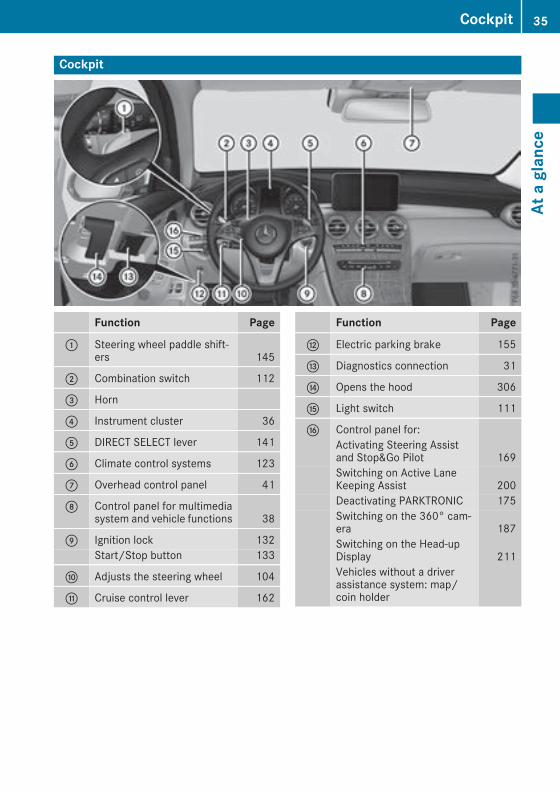
Cockpit
Function Page
: Steering wheel paddle shift-ers 145
; Combination switch 112
= Horn
? Instrument cluster 36
A DIRECT SELECT lever 141
B Climate control systems 123
C Overhead control panel 41
D Control panel for multimediasystem and vehicle functions 38
E Ignition lock 132Start/Stop button 133
F Adjusts the steering wheel 104
G Cruise control lever 162
Function Page
H Electric parking brake 155
I Diagnostics connection 31
J Opens the hood 306
K Light switch 111
L Control panel for:Activating Steering Assistand Stop&Go Pilot 169Switching on Active LaneKeeping Assist 200Deactivating PARKTRONIC 175Switching on the 360° cam-era 187Switching on the Head-upDisplay 211Vehicles without a driverassistance system: map/coin holder
Cockpit 35
Ataglance
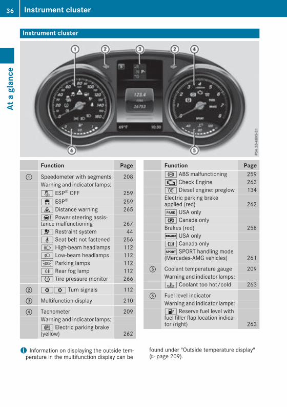
Instrument cluster
Function Page
: Speedometer with segments 208Warning and indicator lamps:å ESP® OFF 259÷ ESP® 259· Distance warning 265Ð Power steering assis-tance malfunctioning 2676 Restraint system 44ü Seat belt not fastened 256K High-beam headlamps 112L Low-beam headlamps 112T Parking lamps 112R Rear fog lamp 112h Tire pressure monitor 266
; #! Turn signals 112
= Multifunction display 210
? Tachometer 209Warning and indicator lamps:! Electric parking brake(yellow) 262
Function Page! ABS malfunctioning 259; Check Engine 263% Diesel engine: preglow 134Electric parking brakeapplied (red) 262F USA only! Canada onlyBrakes (red) 258$ USA onlyJ Canada onlyM SPORT handling mode(Mercedes-AMG vehicles) 261
A Coolant temperature gauge 209Warning and indicator lamps:? Coolant too hot/cold 263
B Fuel level indicatorWarning and indicator lamps:8 Reserve fuel level withfuel filler flap location indica-tor (right) 263
i Information on displaying the outside tem-perature in the multifunction display can be
found under "Outside temperature display"(Y page 209).
36 Instrument clusterAt
aglance
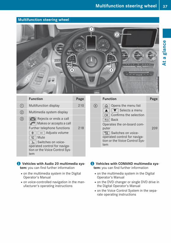
Multifunction steering wheel
Function Page
: Multifunction display 210
; Multimedia system display
= ~ Rejects or ends a call6Makes or accepts a callFurther telephone functions 218WX Adjusts volume8 Muteó Switches on voice-operated control for naviga-tion or the Voice Control Sys-tem
Function Page
? ò Opens the menu list9: Selects a menua Confirms the selection% BackOperates the on-board com-puter 209ñ Switches on voice-operated control for naviga-tion or the Voice Control Sys-tem
i Vehicles with Audio 20 multimedia sys-tem: you can find further informationRon the multimedia system in the DigitalOperator's ManualRon voice-controlled navigation in the man-ufacturer's operating instructions
i Vehicles with COMAND multimedia sys-tem: you can find further informationRon the multimedia system in the DigitalOperator's ManualRon the DVD changer or single DVD drive inthe Digital Operator's ManualRon the Voice Control System in the sepa-rate operating instructions
Multifunction steering wheel 37
Ataglance

Center console
Center console, upper section
Function Page
: Climate control systems 123
; £ Hazard warning lamps 113
= Ø Vehicle functions/system settings button (seeDigital Operator's Manual)
? % Telephone button (seeDigital Operator's Manual)
A PASSENGER AIRBAG indica-tor lamps 44ATA indicator lamp 76
Function Page
B Õ Media button (see Dig-ital Operator's Manual)
C $ Radio button (see Digi-tal Operator's Manual)
D Ø Navigation button (seeDigital Operator's Manual)
E þ Inserts or ejects a CDor DVD (see Digital Opera-tor's Manual)
38 Center consoleAt
aglance

Center console, lower section (except Mercedes-AMG vehicles)
Function Page
: Stowage compartment 278Ashtray 292Cigarette lighter 292Socket 293Cup holder 290
; Adjusts the volume 269Switches the sound on or off 269
= Ü Switches the multime-dia system on/off 269
? Touchpad 270
A Opens stowage compart-ment with Media Interface 278
Function Page
B è ECO start/stop func-tion 136
C c DeactivatesPARKTRONIC 175É Adjusts the vehiclelevel (AIR BODY CONTROL) 173
D DYNAMIC SELECT switch 139
E % Back button 269
F Controller 269
G g Favorites button 271
Center console 39
Ataglance

Center console, lower section (Mercedes-AMG vehicles)
Function Page
: Stowage compartment 278Ashtray 292Cigarette lighter 292Socket 293Cup holder 290
; Adjusts the volume 269Switches the sound on or off 269
= Ü Switches the multime-dia system on/off 269
? è ECO start/stop func-tion 136
A É Adjusts the vehiclelevel (AIR BODY CONTROL) 173
B Opens stowage compart-ment with Media Interface 278
Function Page
C Touchpad 270
D å Activates/deactivatesESP® 71M Activates/deactivatesSPORT handling mode 71
E AMG sports suspensionbased on AIR BODY CON-TROL 174
F Manual gearshifting (perma-nent setting) 145
G DYNAMIC SELECT switch 139
H % Back button 269
I Controller 269
J g Favorites button 271
40 Center consoleAt
aglance
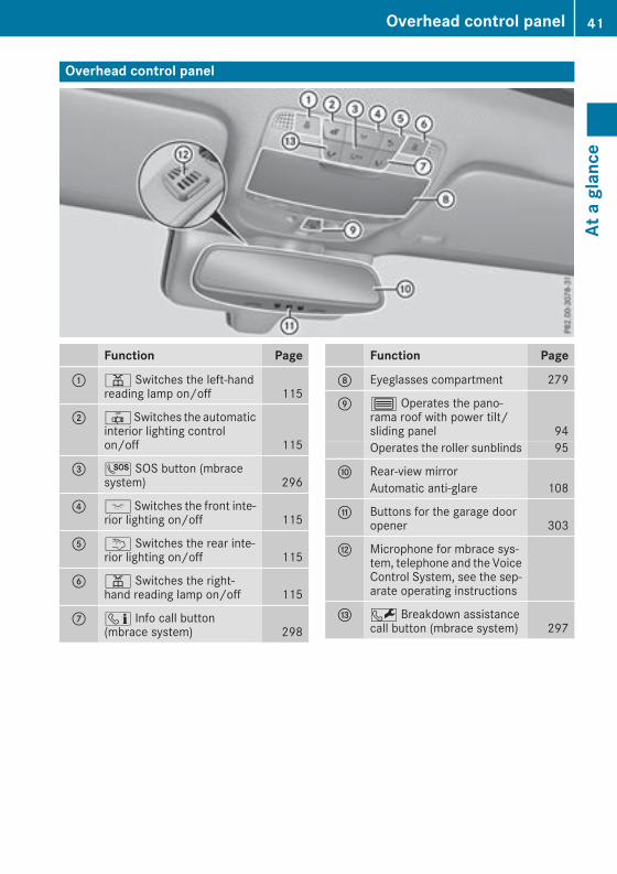
Overhead control panel
Function Page
: p Switches the left-handreading lamp on/off 115
; |Switches the automaticinterior lighting controlon/off 115
= G SOS button (mbracesystem) 296
? c Switches the front inte-rior lighting on/off 115
A u Switches the rear inte-rior lighting on/off 115
B p Switches the right-hand reading lamp on/off 115
C ï Info call button(mbrace system) 298
Function Page
D Eyeglasses compartment 279
E 3 Operates the pano-rama roof with power tilt/sliding panel 94Operates the roller sunblinds 95
F Rear-view mirrorAutomatic anti-glare 108
G Buttons for the garage dooropener 303
H Microphone for mbrace sys-tem, telephone and the VoiceControl System, see the sep-arate operating instructions
I F Breakdown assistancecall button (mbrace system) 297
Overhead control panel 41
Ataglance

Door control panel
Function Page
: r45=Stores settings for the seat,exterior mirrors and steeringcolumn 109
; Adjusts the seats electrically 100
= c Seat heating 102
? s Seat ventilation 103
A Opens the door 83
B %& Unlocks/locksthe vehicle 83
C W Opens/closes the rearleft side window 90
D W Opens/closes the leftside window 90
Function Page
E 7Zª\Adjusts and folds the exteriormirrors out/in electrically 107
F WOpens/closes the rightside window 90
G W Opens/closes the rearright side window 90
H nOverride feature for thecontrols in the rear compart-ment 64
I p Opens/closes the tail-gate 88
42 Door control panelAt
aglance

Panic alarm
X To arm: press and hold the! button:for approximately one second.A visual and audible alarm is triggered if thealarm system is armed.
X To disarm: press the! button: again.orX Insert the SmartKey into the ignition lock.orX Press the Start/Stop button.The SmartKey must be in the vehicle.
Occupant safety
Introduction to the restraint systemThe restraint system can reduce the risk of vehi-cle occupants coming into contact with parts ofthe vehicle's interior in the event of an accident.The restraint system can also reduce the forcestowhich vehicle occupants are subjected duringan accident.The restraint system comprises:Rseat belt systemRair bagsRchild restraint systemRchild seat securing systemsThe components of the restraint system work inconjunction with each other. They can onlydeploy their protective function if, at all times, allvehicle occupants:Rhave fastened their seat belts correctly(Y page 46)Rhave adjusted their seat and head restraintproperly (Y page 98).
As the driver, you also have to make sure thatthe steering wheel is adjusted correctly.Observe the information relating to the correctdriver's seat position (Y page 98).You also have to make sure that an air bag caninflate properly if deployed (Y page 48).An air bag supplements a correctly worn seatbelt. As an additional safety device, the air bagincreases the level of protection for vehicleoccupants in the event of an accident. For exam-ple, if, in the event of an accident, the protectionoffered by the seat belt is sufficient, the air bagsare not deployed.When an accident occurs, onlythe air bags that increase protection in that par-ticular accident situation are deployed. How-ever, seat belts and air bags generally do notprotect against objects penetrating the vehiclefrom the outside.Information on restraint system operation canbe found under "Triggering of the EmergencyTensioning Devices and air bags" (Y page 55).For information on children traveling with you inthe vehicle and on child restraint systems, see"Children in the vehicle" (Y page 59).
Important safety notes
G WARNINGModifications to the restraint system maycause it to no longer work as intended. Therestraint system may then not perform itsintended protective function andmay fail in anaccident or trigger unexpectedly, for example.This poses an increased risk of injury or evenfatal injury.Never modify parts of the restraint system.Never tamper with the wiring, the electroniccomponents or their software.If it is necessary to modify components of therestraint system to accommodate a personwith disabilities, contact an authorizedMercedes-Benz Center for details. USA only:for further information contact our CustomerAssistance Center at 1-800-FOR-MERCedes(1‑800‑367‑6372).
Mercedes-Benz recommends that you only usedriving aids which have been approved specifi-cally for your vehicle by Mercedes-Benz.
Occupant safety 43
Safety
Z
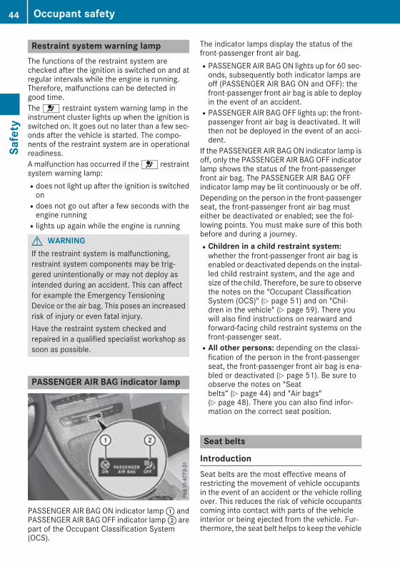
Restraint system warning lampThe functions of the restraint system arechecked after the ignition is switched on and atregular intervals while the engine is running.Therefore, malfunctions can be detected ingood time.The 6 restraint system warning lamp in theinstrument cluster lights up when the ignition isswitched on. It goes out no later than a few sec-onds after the vehicle is started. The compo-nents of the restraint system are in operationalreadiness.Amalfunction has occurred if the 6 restraintsystem warning lamp:Rdoes not light up after the ignition is switchedonRdoes not go out after a few seconds with theengine runningRlights up again while the engine is running
G WARNINGIf the restraint system is malfunctioning,restraint system components may be trig-gered unintentionally or may not deploy asintended during an accident. This can affectfor example the Emergency TensioningDevice or the air bag. This poses an increasedrisk of injury or even fatal injury.Have the restraint system checked andrepaired in a qualified specialist workshop assoon as possible.
PASSENGER AIR BAG indicator lamp
PASSENGER AIR BAG ON indicator lamp: andPASSENGER AIR BAGOFF indicator lamp; arepart of the Occupant Classification System(OCS).
The indicator lamps display the status of thefront-passenger front air bag.RPASSENGER AIR BAG ON lights up for 60 sec-onds, subsequently both indicator lamps areoff (PASSENGER AIR BAG ON and OFF): thefront-passenger front air bag is able to deployin the event of an accident.RPASSENGER AIR BAGOFF lights up: the front-passenger front air bag is deactivated. It willthen not be deployed in the event of an acci-dent.
If the PASSENGER AIR BAG ON indicator lamp isoff, only the PASSENGER AIR BAG OFF indicatorlamp shows the status of the front-passengerfront air bag. The PASSENGER AIR BAG OFFindicator lamp may be lit continuously or be off.Depending on the person in the front-passengerseat, the front-passenger front air bag musteither be deactivated or enabled; see the fol-lowing points. You must make sure of this bothbefore and during a journey.RChildren in a child restraint system:whether the front-passenger front air bag isenabled or deactivated depends on the instal-led child restraint system, and the age andsize of the child. Therefore, be sure to observethe notes on the "Occupant ClassificationSystem (OCS)" (Y page 51) and on "Chil-dren in the vehicle" (Y page 59). There youwill also find instructions on rearward andforward-facing child restraint systems on thefront-passenger seat.RAll other persons: depending on the classi-fication of the person in the front-passengerseat, the front-passenger front air bag is ena-bled or deactivated (Y page 51). Be sure toobserve the notes on "Seatbelts“ (Y page 44) and "Air bags"(Y page 48). There you can also find infor-mation on the correct seat position.
Seat belts
IntroductionSeat belts are the most effective means ofrestricting the movement of vehicle occupantsin the event of an accident or the vehicle rollingover. This reduces the risk of vehicle occupantscoming into contact with parts of the vehicleinterior or being ejected from the vehicle. Fur-thermore, the seat belt helps to keep the vehicle
44 Occupant safetySafety
occupant in the best position in relation to theair bag.The seat belt system comprises:RSeat beltsREmergency Tensioning Devices for the frontseat belts and the outer seat belts in the rearRSeat belt force limiters for the front seat beltsand the outer seat belts in the rear
If the seat belt is pulled out of the belt outletquickly or with a jerky movement, the beltretractor locks. The belt strap cannot be extrac-ted any further.The Emergency Tensioning Device tightens theseat belt in an accident, pulling the belt closeagainst the body. However it does not pull thevehicle occupant back in the direction of thebackrest.The Emergency Tensioning Device does not cor-rect an incorrect seat position or the routing ofan incorrectly fastened seat belt.When triggered, a seat belt force limiter helps toreduce the force exerted by the seat belt on thevehicle occupant.The seat belt force limiters for the front seats aresynchronized with the front air bags, whichabsorb part of the deceleration force. This canreduce the force exerted on the vehicle occu-pants during an accident.
! If the front-passenger seat is unoccupied,do not insert the belt tongue into the buckle ofthe front-passenger seat. This may otherwiselead to the triggering of the Emergency Ten-sioning Device in the event of an accident,which will then need to be replaced.
Important safety notesThe use of seat belts and child restraint systemsis required by law in:Rall 50 statesRthe U.S. territoriesRthe District of ColumbiaRall Canadian provincesEvenwhere this is not required by law, all vehicleoccupants should correctly fasten their seatbelts before starting the journey.
G WARNINGIf the seat belt is not worn correctly, it cannotperform its intended protective function. Anincorrectly fastened seat belt can also cause
injuries, for example, in the event of an acci-dent or when braking or changing directionabruptly. This poses an increased risk of injuryor even fatal injury.Always ensure that all vehicle occupants havetheir seat belts fastened correctly and are sit-ting properly.
G WARNINGThe seat belt does not offer the intended levelof protection if you have not moved the back-rest to an almost vertical position.When brak-ing or in the event of an accident, you couldslide underneath the seat belt and sustainabdomen or neck injuries, for example. Thisposes an increased risk of injury or even fatalinjury.Adjust the seat properly before beginningyour journey. Always ensure that the backrestis in an almost vertical position and that theshoulder section of your seat belt is routedacross the center of your shoulder.
G WARNINGPersons less than 5 ft (1.50 m) tall cannotwear the seat belt correctly without an addi-tional and suitable restraint system. If theseat belt is not worn correctly, it cannot per-form its intended protective function. Anincorrectly fastened seat belt can also causeinjuries, for example, in the event of an acci-dent or when braking or changing directionabruptly. This poses an increased risk of injuryor even fatal injury.For this reason, always secure persons under5 ft (1.50m) tall in suitable additional restraintsystems.
If a child younger than twelve years old andunder 5 ft (1.50 m) in height is traveling in thevehicle:Ralways secure the child in a child restraintsystem suitable for this Mercedes-Benz vehi-cle. The child restraint systemmust be appro-priate to the age, weight and size of the childRalways observe the instructions and safetynotes on "Children in the vehicle"(Y page 59) in addition to the child restraint
Occupant safety 45
Safety
Z

system manufacturer's installation and oper-ating instructionsRalways observe the instructions and safetynotes on the "Occupant classification system(OCS)" (Y page 51)
G WARNINGThe seat belts may not perform their intendedprotective function if:Rthey are damaged, modified, extremelydirty, bleached or dyedRthe seat belt buckle is damaged orextremely dirtyRthe Emergency Tensioning Devices, beltanchorages or inertia reels have beenmodi-fied.
Seat belts may be damaged in an accident,although the damage may not be visible, e.g.due to splinters of glass.Modified or damagedseat belts may tear or fail, e.g. in an accident.Modified Emergency Tensioning Devicescould accidentally trigger or fail to deploywhen necessary. This poses an increased riskof injury or even fatal injury.Never modify the seat belts, Emergency Ten-sioning Devices, belt anchorages and inertiareels. Make sure that the seat belts areundamaged, not worn out and clean. Follow-ing an accident, have the seat belts checkedimmediately at a qualified specialist work-shop.
Only use seat belts that have been approved foryour vehicle by Mercedes-Benz.AMG Performance seat: this seat is designedfor the standard three-point seat belt. If youinstall anothermulti-point seat belt, e.g. sport orracing seat belts, the restraint system cannotprovide the best level of protection.
G WARNINGIf you feed seat belts through the opening inthe seat backrest, the seat backrest may bedamaged or may even break in the event of anaccident. This poses an increased risk ofinjury or even fatal injury.Only use the standard three-point seat belt.Never modify the seat belt system.
Proper use of the seat beltsObserve the safety notes on the seat belt(Y page 45).All vehicle occupants must be wearing the seatbelt correctly before beginning the journey. Alsomake sure that all vehicle occupants are alwayswearing the seat belt correctly while the vehicleis in motion.When fastening the seat belt, always make surethat:Rthe seat belt tongue is only inserted to the beltbuckle belonging to that seat.Rthe seat belt is tight across your body.Avoid wearing bulky clothing, e.g. a wintercoat.Rthe seat belt is not twisted.Only then can the forces which occur be dis-tributed over the area of the belt.Rthe shoulder section of the belt is alwaysrouted across the center of your shoulder.The shoulder section of the belt must notcome into contact with your neck or be routedunder your arm. Where possible, adjust theseat belt to the appropriate height.Rthe lap belt passes tightly and as low down aspossible across your lap.The lap belt must always be routed acrossyour hip joints and not across your abdomen.This applies particularly to pregnant women.If necessary, push the lap belt down to yourhip joint and pull it tight using the shouldersection of the belt.Rthe seat belt is not routed across sharp, poin-ted or fragile objects.If you have such items located on or in yourclothing, e.g. pens, keys or eyeglasses, storethese in a suitable place.Ronly one person is using a seat belt at a time.Infants and children must never travel sittingon the lap of a vehicle occupant. In the eventof an accident, they could be crushedbetween the vehicle occupant and seat belt.Robjects are never secured with a seat belt ifthe seat belt is also being used by one of thevehicle's occupants.Also ensure that there are never objectsbetween a person and the seat, e.g. cushions.
Seat belts are only intended to secure andrestrain vehicle occupants. Always observe the"Loading guidelines" for securing objects, lug-gage or loads (Y page 278).
46 Occupant safetySafety

Fastening and adjusting the seat beltsObserve the safety notes on the seat belt(Y page 45) and the notes on correct use of seatbelts (Y page 46).If the center rear seat belt is being used, alsoobserve the information about the seat belt forthe center rear seat (Y page 47).
Basic illustrationX Adjust the seat (Y page 98).The seat backrest must be in an almostupright position.
X Pull the seat belt smoothly from the belt outletand engage belt tongue; into beltbuckle:.The seat belt on the driver’s seat and thefront-passenger seat may be tightened auto-matically, see "Belt adjustment"(Y page 47).
X If necessary, pull up on the shoulder sectionof the seat belt to tighten the belt across yourbody.
The shoulder section of the seat belt mustalways be routed across the center of the shoul-der. Adjust the belt outlet if necessary.X To raise: slide the belt outlet up.The belt outlet will engage in various posi-tions.
X To lower: hold belt outlet release= and slidethe belt outlet down.
X Let go of belt outlet release= in the desiredposition and make sure that the belt outletengages.
All seat belts except the driver's seat belt areequipped with a special seat belt retractor tosecurely fasten child restraint systems in thevehicle. Further information can be found under"Special seat belt retractor" (Y page 59).
Seat belt for the center rear seatIf the left-hand rear seat backrest is folded downand back up again, the rear center seat belt maylock. The seat belt can then not be pulled out.X To release the rear center seat belt: pullthe seat belt out approximately 1 in (25 mm)at the belt outlet on the backrest and thenrelease it again.The seat belt is retracted and released.
Releasing seat belts! Make sure that the seat belt is fully rolled up.Otherwise, the seat belt or belt tongue will betrapped in the door or in the seat mechanism.This could damage the door, the door trimpanel and the seat belt. Damaged seat beltscan no longer fulfill their protective functionand must be replaced. Visit a qualified spe-cialist workshop.
X Press the release button in the belt buckle,hold the belt tongue firmly and guide the beltback.
Seat belt adjustmentThe seat-belt adjustment is an integral part ofthe PRE-SAFE® convenience function. This func-tion adjusts the driver's and front-passengerseat belt to the upper body of the occupants.The belt strap is tightened slightly when:Rthe belt tongue is engaged in the buckle andRthe ignition is switched onThe seat-belt adjustment will apply a certainretraction force if any slack is detected betweenthe vehicle occupant and the seat belt. Do nothold on to the seat belt tightly while it is adjust-ing.You can activate and deactivate the seat-beltadjustment function using the multimedia sys-tem. Information on activating and deactivatingthe seat-belt adjustment function can be foundin the Digital Operator's Manual.
Belt warning for the driver and frontpassengerThe 7 seat belt warning lamp in the instru-ment cluster is a reminder that all vehicle occu-pants must wear their seat belts. It may light upcontinuously or flash. In addition, there may bea warning tone.
Occupant safety 47
Safety
Z

Regardless of whether the driver's seat belt hasalready been fastened, the 7 seat belt warn-ing lamp lights up for six seconds each time theengine is started. If, after six seconds, the driveror front-passenger seat belt has not been fas-tened and the doors are closed, the 7 seatbelt warning lamp lights up. As soon as the driv-er's and front-passenger seat belts are fastenedor a front door is opened again, the 7 seatbelt warning lamp goes out.If the driver's seat belt is not fastened after theengine is started, an additional warning tone willsound. The warning tone switches off after sixseconds or once the driver's seat belt is fas-tened.If the vehicle's speed exceeds 15 mph(25 km/h) once and the driver's and front-passenger seat belts are not fastened, awarningtone sounds. A warning tone also sounds withincreasing intensity for 60 seconds or until thedriver or front passenger have fastened theirseat belts.If the driver or front passenger unfasten theirseat belts during the journey, the seat belt warn-ing is activated again.
Air bags
IntroductionThe installation point of an air bag can be rec-ognized by the AIR BAG symbol.An air bag complements the correctly fastenedseat belt. It is no substitute for the seat belt. Theair bag provides additional protection in appli-cable accident situations.Not all air bags are deployed in an accident. Thedifferent air bag systems function independ-ently from one another (Y page 55).However, no system available today can com-pletely eliminate injuries and fatalities.It is also not possible to rule out a risk of injurycaused by an air bag due to the high speed atwhich the air bag must be deployed.
Important safety notes
G WARNINGIf you do not sit in the correct seat position,the air bag cannot protect as intended andcould even cause additional injury when
deployed. This poses an increased risk ofinjury or even fatal injury.To avoid hazardous situations, always makesure that all of the vehicle's occupants:Rhave fastened their seat belts correctly,including pregnant womenRare sitting correctly andmaintain the great-est possible distance to the air bagsRfollow the following instructionsAlways make sure that there are no objectsbetween the air bag and the vehicle's occu-pants.
RAdjust the seats properly before beginningyour journey. Always make sure that the seatis in an almost upright position. The center ofthe head restraint must support the head atabout eye level.RMove the driver's and front-passenger seatsas far back as possible. The driver's seat posi-tionmust allow the vehicle to be driven safely.ROnly hold the steering wheel on the outside.This allows the air bag to be fully deployed.RAlways lean against the backrest while driv-ing. Do not lean forwards or lean against thedoor or side window. Youmay otherwise be inthe deployment area of the air bags.RAlways keep your feet in the footwell in frontof the seat. Do not put your feet on the dash-board, for example. Your feet may otherwisebe in the deployment area of the air bag.RFor this reason, always secure persons lessthan 5 ft (1.50 m) tall in suitable restraint sys-tems. Up to this height, the seat belt cannotbe worn correctly.
If a child is traveling in your vehicle, alsoobserve the following notes:RAlways secure children under twelve years ofage and less than 5 ft (1.50 m) tall in suitablechild restraint systems.RChild restraint systems should be installed onthe rear seats.ROnly secure a child in a rearward-facing childrestraint system on the front-passenger seatwhen the front-passenger front air bag isdeactivated. If the PASSENGER AIR BAG OFFindicator lamp is permanently lit, the front-
48 Occupant safetySafety
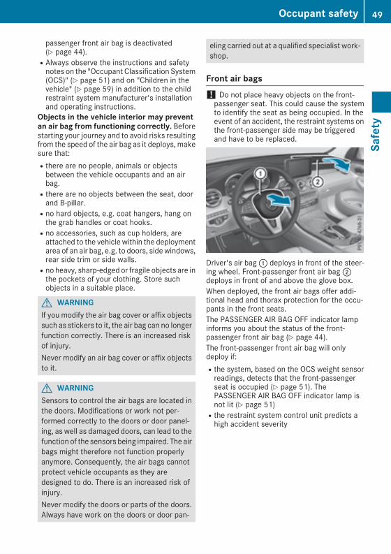
passenger front air bag is deactivated(Y page 44).RAlways observe the instructions and safetynotes on the "Occupant Classification System(OCS)" (Y page 51) and on "Children in thevehicle" (Y page 59) in addition to the childrestraint system manufacturer's installationand operating instructions.
Objects in the vehicle interior may preventan air bag from functioning correctly. Beforestarting your journey and to avoid risks resultingfrom the speed of the air bag as it deploys, makesure that:Rthere are no people, animals or objectsbetween the vehicle occupants and an airbag.Rthere are no objects between the seat, doorand B-pillar.Rno hard objects, e.g. coat hangers, hang onthe grab handles or coat hooks.Rno accessories, such as cup holders, areattached to the vehicle within the deploymentarea of an air bag, e.g. to doors, side windows,rear side trim or side walls.Rno heavy, sharp-edged or fragile objects are inthe pockets of your clothing. Store suchobjects in a suitable place.
G WARNINGIf you modify the air bag cover or affix objectssuch as stickers to it, the air bag can no longerfunction correctly. There is an increased riskof injury.Never modify an air bag cover or affix objectsto it.
G WARNINGSensors to control the air bags are located inthe doors. Modifications or work not per-formed correctly to the doors or door panel-ing, as well as damaged doors, can lead to thefunction of the sensors being impaired. The airbags might therefore not function properlyanymore. Consequently, the air bags cannotprotect vehicle occupants as they aredesigned to do. There is an increased risk ofinjury.Never modify the doors or parts of the doors.Always have work on the doors or door pan-
eling carried out at a qualified specialist work-shop.
Front air bags! Do not place heavy objects on the front-passenger seat. This could cause the systemto identify the seat as being occupied. In theevent of an accident, the restraint systems onthe front-passenger side may be triggeredand have to be replaced.
Driver's air bag: deploys in front of the steer-ing wheel. Front-passenger front air bag;deploys in front of and above the glove box.When deployed, the front air bags offer addi-tional head and thorax protection for the occu-pants in the front seats.The PASSENGER AIR BAG OFF indicator lampinforms you about the status of the front-passenger front air bag (Y page 44).The front-passenger front air bag will onlydeploy if:Rthe system, based on the OCS weight sensorreadings, detects that the front-passengerseat is occupied (Y page 51). ThePASSENGER AIR BAG OFF indicator lamp isnot lit (Y page 51)Rthe restraint system control unit predicts ahigh accident severity
Occupant safety 49
Safety
Z
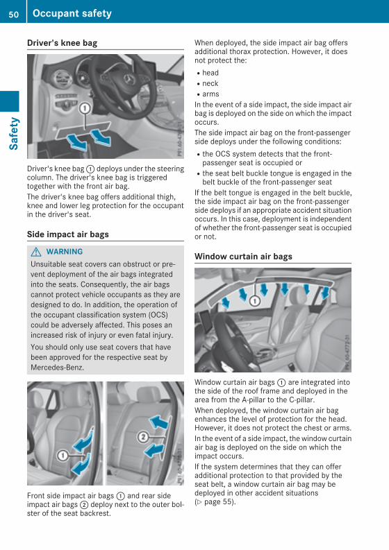
Driver's knee bag
Driver's knee bag: deploys under the steeringcolumn. The driver's knee bag is triggeredtogether with the front air bag.The driver's knee bag offers additional thigh,knee and lower leg protection for the occupantin the driver's seat.
Side impact air bags
G WARNINGUnsuitable seat covers can obstruct or pre-vent deployment of the air bags integratedinto the seats. Consequently, the air bagscannot protect vehicle occupants as they aredesigned to do. In addition, the operation ofthe occupant classification system (OCS)could be adversely affected. This poses anincreased risk of injury or even fatal injury.You should only use seat covers that havebeen approved for the respective seat byMercedes-Benz.
Front side impact air bags: and rear sideimpact air bags; deploy next to the outer bol-ster of the seat backrest.
When deployed, the side impact air bag offersadditional thorax protection. However, it doesnot protect the:RheadRneckRarmsIn the event of a side impact, the side impact airbag is deployed on the side on which the impactoccurs.The side impact air bag on the front-passengerside deploys under the following conditions:Rthe OCS system detects that the front-passenger seat is occupied orRthe seat belt buckle tongue is engaged in thebelt buckle of the front-passenger seat
If the belt tongue is engaged in the belt buckle,the side impact air bag on the front-passengerside deploys if an appropriate accident situationoccurs. In this case, deployment is independentof whether the front-passenger seat is occupiedor not.
Window curtain air bags
Window curtain air bags: are integrated intothe side of the roof frame and deployed in thearea from the A-pillar to the C-pillar.When deployed, the window curtain air bagenhances the level of protection for the head.However, it does not protect the chest or arms.In the event of a side impact, the window curtainair bag is deployed on the side on which theimpact occurs.If the system determines that they can offeradditional protection to that provided by theseat belt, a window curtain air bag may bedeployed in other accident situations(Y page 55).
50 Occupant safetySafety

Occupant Classification System(OCS)
IntroductionThe Occupant Classification System (OCS) cat-egorizes the person in the front-passenger seat.Depending on that result, the front-passengerfront air bag is either enabled or deactivated.The system does not deactivate:Rthe side impact air bagRthe window curtain air bagRthe Emergency Tensioning Devices
RequirementsTo be classified correctly, the front passengermust sit:Rwith the seat belt fastened correctlyRin an almost upright position with their backagainst the seat backrestRwith their feet resting on the floor, if possibleIf the front passenger does not observe theseconditions, OCS may produce a false classifica-tion, e.g. because the front passenger:Rtransfers their weight by supporting them-selves on a vehicle armrestRsits in such a way that their weight is raisedfrom the seat cushion
If it is absolutely necessary to install a childrestraint system on the front-passenger seat, besure to observe the correct positioning of thechild restraint system. Never place objectsunder or behind the child restraint system, e.g. acushion. Fully retract the seat cushion length.The entire base of the child restraint systemmust always rest on the seat cushion of thefront-passenger seat. The backrest of theforward-facing child restraint systemmust lie asflat as possible against the backrest of the front-passenger seat.The child restraint system must not touch theroof or be subjected to a load by the headrestraint. Adjust the angle of the seat backrestand the head restraint position accordingly.Only then can OCS be guaranteed to functioncorrectly. Always observe the child restraint sys-tem manufacturer's installation and operatinginstructions.
Occupant Classification System opera-tion (OCS)
: PASSENGER AIR BAG ON indicator lamp; PASSENGER AIR BAG OFF indicator lampThe indicator lamps inform you whether thefront-passenger front air bag is deactivated orenabled.X Press the Start/Stop button once or twice, orturn the SmartKey to position 1 or 2 in theignition lock.The system carries out self-diagnostics.
The PASSENGER AIR BAG OFF and PASSENGERAIR BAGON indicator lampsmust light up simul-taneously for approximately six seconds.The indicator lamps display the status of thefront-passenger front air bag.RPASSENGER AIR BAG ON lights up for 60 sec-onds, subsequently both indicator lamps areoff (PASSENGER AIR BAG ON and OFF): thefront-passenger front air bag is able to deployin the event of an accident.RPASSENGER AIR BAGOFF lights up: the front-passenger front air bag is deactivated. It willthen not be deployed in the event of an acci-dent.
If the PASSENGER AIR BAG ON indicator lamp isoff, only the PASSENGER AIR BAG OFF indicatorlamp shows the status of the front-passengerfront air bag. The PASSENGER AIR BAG OFFindicator lamp may be lit continuously or be off.If the status of the front-passenger front air bagchangeswhile the vehicle is inmotion, an air bagdisplaymessage appears in the instrument clus-ter (Y page 237). When the front-passengerseat is occupied, always pay attention to thePASSENGER AIR BAG OFF indicator lamp. Beaware of the status of the front-passenger frontair bag both before and during the journey.
Occupant safety 51
Safety
Z

G WARNINGIf the PASSENGER AIR BAG OFF indicatorlamp is lit, the front-passenger front air bag isdisabled. It will not be deployed in the event ofan accident and cannot perform its intendedprotective function. A person in the front-passenger seat could then, for example, comeinto contact with the vehicle's interior, espe-cially if the person is sitting too close to thedashboard. This poses an increased risk ofinjury or even fatal injury.When the front-passenger seat is occupied,always ensure that:Rthe classification of the person in the front-passenger seat is correct and the front-passenger front air bag is enabled or disa-bled in accordance with the person in thefront-passenger seatRthe front-passenger seat has been movedback as far back as possible.Rthe person is seated correctly.Make sure, both before and during the jour-ney, that the status of the front-passengerfront air bag is correct.
G WARNINGIf you secure a child in a rearward-facing childrestraint system on the front-passenger seatand the PASSENGER AIR BAG OFF indicatorlamp is off, the front-passenger front air bagmay deploy in the event of an accident. Thechild could be struck by the air bag. This posesan increased risk of injury or even fatal injury.Make sure that the front-passenger front airbag has been disabled. The PASSENGER AIRBAG OFF indicator lamp must be lit.
If the PASSENGER AIR BAG OFF indicator lampstays off, do not install a rearward-facing childrestraint system on the front-passenger seat.You can find more information on OCS under"Problemswith theOccupant Classification Sys-tem" (Y page 54).
G WARNINGIf you secure a child in a forward-facing childrestraint system on the front-passenger seatand you position the front-passenger seat tooclose to the dashboard, in the event of anaccident, the child could:Rcome into contact with the vehicle's inte-rior if the PASSENGER AIR BAG OFF indi-cator lamp is lit, for exampleRbe struck by the air bag if the PASSENGERAIR BAG OFF indicator lamp is off
This poses an increased risk of injury or evenfatal injury.Always move the front-passenger seat as farback as possible and fully retract the seatcushion length. Always make sure that theshoulder belt strap is correctly routed fromthe vehicle belt sash guide to the shoulderbelt guide on the child restraint system. Theshoulder belt strap must be routed forwardsand downwards from the vehicle belt sashguide. If necessary, adjust the vehicle beltsash guide and the front-passenger seataccordingly. Always observe the childrestraint system manufacturer's installationinstructions.
If OCS determines that:Rthe front-passenger seat is unoccupied, thePASSENGER AIR BAG OFF indicator lamplights up after the system self-test andremains lit. This indicates that the front-passenger front air bag is deactivated.Rthe front-passenger seat is occupied by achild of up to twelvemonths old, in a standardchild restraint system, the PASSENGER AIRBAG OFF indicator lamp lights up after thesystem self-test and remains lit. This indi-cates that the front-passenger front air bag isdeactivated.But even in the case of a twelve-month-oldchild, in a standard child restraint system, thePASSENGER AIR BAG OFF indicator lamp cango out after the system self-test. This indi-cates that the front-passenger front air bag isactivated. The result of the classification isdependent on, among other factors, the childrestraint system and the child's stature. It is
52 Occupant safetySafety
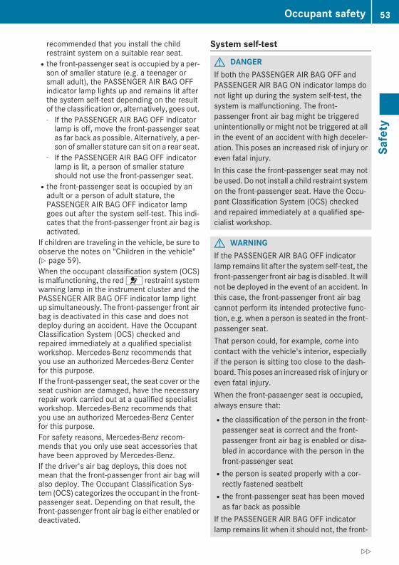
recommended that you install the childrestraint system on a suitable rear seat.Rthe front-passenger seat is occupied by a per-son of smaller stature (e.g. a teenager orsmall adult), the PASSENGER AIR BAG OFFindicator lamp lights up and remains lit afterthe system self-test depending on the resultof the classification or, alternatively, goes out.- If the PASSENGER AIR BAG OFF indicatorlamp is off, move the front-passenger seatas far back as possible. Alternatively, a per-son of smaller stature can sit on a rear seat.
- If the PASSENGER AIR BAG OFF indicatorlamp is lit, a person of smaller statureshould not use the front-passenger seat.
Rthe front-passenger seat is occupied by anadult or a person of adult stature, thePASSENGER AIR BAG OFF indicator lampgoes out after the system self-test. This indi-cates that the front-passenger front air bag isactivated.
If children are traveling in the vehicle, be sure toobserve the notes on "Children in the vehicle"(Y page 59).When the occupant classification system (OCS)is malfunctioning, the red 6 restraint systemwarning lamp in the instrument cluster and thePASSENGER AIR BAG OFF indicator lamp lightup simultaneously. The front-passenger front airbag is deactivated in this case and does notdeploy during an accident. Have the OccupantClassification System (OCS) checked andrepaired immediately at a qualified specialistworkshop. Mercedes-Benz recommends thatyou use an authorized Mercedes-Benz Centerfor this purpose.If the front-passenger seat, the seat cover or theseat cushion are damaged, have the necessaryrepair work carried out at a qualified specialistworkshop. Mercedes-Benz recommends thatyou use an authorized Mercedes-Benz Centerfor this purpose.For safety reasons, Mercedes-Benz recom-mends that you only use seat accessories thathave been approved by Mercedes-Benz.If the driver's air bag deploys, this does notmean that the front-passenger front air bag willalso deploy. The Occupant Classification Sys-tem (OCS) categorizes the occupant in the front-passenger seat. Depending on that result, thefront-passenger front air bag is either enabled ordeactivated.
System self-test
G DANGERIf both the PASSENGER AIR BAG OFF andPASSENGER AIR BAG ON indicator lamps donot light up during the system self-test, thesystem is malfunctioning. The front-passenger front air bag might be triggeredunintentionally or might not be triggered at allin the event of an accident with high deceler-ation. This poses an increased risk of injury oreven fatal injury.In this case the front-passenger seat may notbe used. Do not install a child restraint systemon the front-passenger seat. Have the Occu-pant Classification System (OCS) checkedand repaired immediately at a qualified spe-cialist workshop.
G WARNINGIf the PASSENGER AIR BAG OFF indicatorlamp remains lit after the system self-test, thefront-passenger front air bag is disabled. It willnot be deployed in the event of an accident. Inthis case, the front-passenger front air bagcannot perform its intended protective func-tion, e.g. when a person is seated in the front-passenger seat.That person could, for example, come intocontact with the vehicle's interior, especiallyif the person is sitting too close to the dash-board. This poses an increased risk of injury oreven fatal injury.When the front-passenger seat is occupied,always ensure that:Rthe classification of the person in the front-passenger seat is correct and the front-passenger front air bag is enabled or disa-bled in accordance with the person in thefront-passenger seatRthe person is seated properly with a cor-rectly fastened seatbeltRthe front-passenger seat has been movedas far back as possible
If the PASSENGER AIR BAG OFF indicatorlamp remains lit when it should not, the front-
Occupant safety 53
Safety
Z

passenger seat may not be used. Do notinstall a child restraint system on the front-passenger seat. Have the Occupant Classifi-cation System (OCS) checked and repairedimmediately at a qualified specialist work-shop.
G WARNINGObjects between the seat surface and thechild restraint system could affect OCS oper-ation. This could result in the front-passengerair bag not functioning as intended during anaccident. This poses an increased risk ofinjury or even fatal injury.Do not place any objects between the seatsurface and the child restraint system. Theentire base of the child restraint system mustalways rest on the seat cushion of the front-passenger seat. The backrest of the forward-
facing child restraint system must, as far aspossible, be resting on the backrest of thefront-passenger seat. Always comply with thechild restraint system manufacturer's instal-lation instructions.
After the system self-test, the PASSENGER AIRBAG OFF or PASSENGER AIR BAG ON indicatorlamp displays the status of the front-passengerfront air bag (Y page 51). If the front-passengerfront air bag is enabled, the PASSENGER AIRBAG ON indicator lamp lights up for 60 secondsand then goes out.If the PASSENGER AIR BAG ON indicator lamp isoff, only the PASSENGER AIR BAG OFF indicatorlamp shows the status of the front-passengerfront air bag. The PASSENGER AIR BAG OFFindicator lamp may be lit continuously or be off.For more information about the OCS, see "Prob-lems with the Occupant Classification System"(Y page 54).
Problems with the Occupant Classification System (OCS)Be sure to observe the notes on "System self-test" (Y page 53).
54 Occupant safetySafety
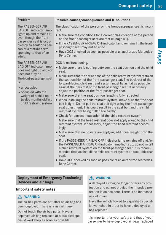
Problem Possible causes/consequences andM Solutions
The PASSENGER AIRBAG OFF indicator lamplights up and remains lit,even though the front-passenger seat is occu-pied by an adult or a per-son of a stature corre-sponding to that of anadult.
The classification of the person on the front-passenger seat is incor-rect.X Make sure the conditions for a correct classification of the personon the front-passenger seat are met (Y page 51).
X If the PASSENGERAIR BAGOFF indicator lamp remains lit, the front-passenger seat may not be used.
X Have OCS checked as soon as possible at an authorized Mercedes-Benz Center.
The PASSENGER AIRBAG OFF indicator lampdoes not light up and/ordoes not stay on.The front-passenger seatis:RunoccupiedRoccupied with theweight of a child up totwelve months old in achild restraint system
OCS is malfunctioning.X Make sure there is nothing between the seat cushion and the childseat.
X Make sure that the entire base of the child restraint system rests onthe seat cushion of the front-passenger seat. The backrest of theforward-facing child restraint system must lie as flat as possibleagainst the backrest of the front-passenger seat. If necessary,adjust the position of the front-passenger seat.
X Make sure that the seat cushion length is fully retracted.X When installing the child restraint system, make sure that the seatbelt is tight. Do not pull the seat belt tight using the front-passengerseat adjustment. This could result in the seat belt and the childrestraint system being pulled too tightly.
X Check for correct installation of the child restraint system.Make sure that the head restraint does not apply a load to the childrestraint system. If necessary, adjust the head restraint accord-ingly.
X Make sure that no objects are applying additional weight onto theseat.
X If the PASSENGER AIR BAG OFF indicator lamp remains off and/orthe PASSENGER AIR BAG ON indicator lamp lights up, do not installa child restraint system on the front-passenger seat. It is recom-mended that you install the child restraint system on a suitable rearseat.
X Have OCS checked as soon as possible at an authorized Mercedes-Benz Center.
Deployment of Emergency TensioningDevices and air bags
Important safety notes
G WARNINGThe air bag parts are hot after an air bag hasbeen deployed. There is a risk of injury.Do not touch the air bag parts. Have adeployed air bag replaced at a qualified spe-cialist workshop as soon as possible.
G WARNINGA deployed air bag no longer offers any pro-tection and cannot provide the intended pro-tection in an accident. There is an increasedrisk of injury.Have the vehicle towed to a qualified special-ist workshop in order to have a deployed airbag replaced.
It is important for your safety and that of yourpassenger to have deployed air bags replaced
Occupant safety 55
Safety
Z

and to have any malfunctioning air bagsrepaired. This will help to make sure the air bagscontinue to perform their protective function forthe vehicle occupants in the event of a crash.
G WARNINGEmergency Tensioning Devices that havedeployed pyrotechnically are no longer opera-tional and are unable to perform their inten-ded protective function. This poses anincreased risk of injury or even fatal injury.Have pyrotechnically triggered EmergencyTensioning Devices replaced immediately at aqualified specialist workshop.
An electric motor is used by PRE-SAFE® to trig-ger the tightening of the seat belt in hazardoussituations. This procedure is reversible.If Emergency Tensioning Devices are triggeredor air bags are deployed, you will hear a bang,and a small amount of powder may also bereleased. The 6 restraint system warninglamp lights up.Only in rare cases will the bang affect your hear-ing. The powder that is released generally doesnot constitute a health hazard, but it may causeshort-term breathing difficulties in people withasthma or other respiratory problems. Providedit is safe to do so, you should leave the vehicleimmediately or open the window in order to pre-vent breathing difficulties.Air bags and pyrotechnic Emergency TensioningDevices (ETDs) contain perchlorate material,which may require special handling and regardfor the environment. National guidelines mustbe observed during disposal. In California, seewww.dtsc.ca.gov/HazardousWaste/Perchlorate/index.cfm.
Method of operationDuring the first stage of a collision, the restraintsystem control unit evaluates important physi-cal data relating to vehicle deceleration or accel-eration, such as:RdurationRdirectionRintensityBased on the evaluation of this data, therestraint system control unit triggers the Emer-gency Tensioning Devices during a frontal orrear collision.
An Emergency Tensioning Device can only betriggered, if:Rthe ignition is switched onRthe components of the restraint system areoperational. You can find further informationunder: "Restraint system warning lamp"(Y page 44)Rthe seat belt buckle tongue has engaged inthe belt buckle of the respective front seat
The Emergency Tensioning Devices in the rearcompartment are triggered independently of thelock status of the seat belts.If the restraint system control unit detects amore severe accident, further components ofthe restraint system are activated independ-ently of each other in certain frontal collisionsituations:RFront air bags and driver's knee bagRWindow curtain air bag, if the system deter-mines that deployment can offer additionalprotection to that provided by the seat belt
The front-passenger front air bag is activated ordeactivated depending on the person on thefront-passenger seat. The front-passenger frontair bag can only deploy in an accident if thePASSENGER AIR BAG OFF indicator lamp is off.Observe the information on the PASSENGERAIRBAG indicator lamps (Y page 44).Your vehicle has two-stage front air bags. Duringthe first deployment stage, the front air bag isfilled with propellant gas to reduce the risk ofinjuries. The front air bag is fully deployed withthe maximum amount of propellant gas if a sec-ond deployment threshold is reached within afew milliseconds.The activation threshold of the Emergency Ten-sioning Devices and the air bag are determinedby evaluating the rate of vehicle deceleration oracceleration which occurs at various points inthe vehicle. This process is pre-emptive innature. Deployment should take place in goodtime at the start of the collision.The rate of vehicle deceleration or accelerationand the direction of the force are essentiallydetermined by:Rthe distribution of forces during the collisionRthe collision angleRthe deformation characteristics of the vehicleRthe characteristics of the object with whichthe vehicle has collided
Factors which can only be seen and measuredafter a collision has occurred do not play a deci-
56 Occupant safetySafety

sive role in the deployment of an air bag. Nor dothey provide an indication of air bag deploy-ment.The vehicle can be deformed considerably, with-out an air bag being deployed. This is the case ifonly parts which are relatively easily deformedare affected and the rate of deceleration is nothigh. Conversely, air bagsmay be deployed eventhough the vehicle suffers only minor deforma-tion. This is the case if, for example, very rigidvehicle parts such as longitudinal body mem-bers are hit, and sufficient deceleration occursas a result.If the restraint system control unit detects a sideimpact or if the vehicle rolls over, the applicablecomponents of the restraint system are activa-ted independently of each other depending onthe apparent type of accident.RSide impact air bags on the side where theimpact takes place, independently of theEmergency Tensioning Device and the use ofthe seat belt on the driver's seat and outerseats in the second rowThe side impact air bag on the front-passenger side deploys under the followingconditions:- the OCS system detects that the front-passenger seat is occupied or
- the seat belt buckle tongue is engaged inthe belt buckle of the front-passenger seat
RWindow curtain air bag on the side of impact,independently of the use of the seat belt andindependently of whether the front-passenger seat is occupiedRFront Emergency Tensioning Devices, if thesystem determines that deployment can offeradditional protection for the vehicle occu-pants in this situationRRear Emergency Tensioning Devices in cer-tain situations if the vehicle rolls overRWindow curtain air bags on the driver's andfront-passenger side in certain situationswhen the vehicle rolls over, if the systemdetermines that deployment can offer addi-tional protection to that provided by the seatbelt
i Not all air bags are deployed in an accident.The different air bag systems work independ-ently of each other.
How the air bag system works is determinedby the severity of the accident detected,especially the vehicle deceleration or accel-eration and the apparent type of accident:RFrontal collisionRSide impactRRollover
PRE-SAFE® (anticipatory occupantprotection system)
IntroductionIn certain hazardous situations, PRE-SAFE®takes pre-emptivemeasures to protect the vehi-cle occupants.
Important safety notes! Make sure that there are no objects in thefootwell or behind the seats. There is a dangerthat the seats and/or objects could be dam-aged when PRE-SAFE® is activated.
Despite your vehicle being equipped with thePRE-SAFE® system, the possibility of personalinjuries occurring as a result of an accident can-not be eliminated. Always adapt your drivingstyle to suit the prevailing road and weatherconditions and maintain a safe distance fromthe vehicle in front. Drive carefully.
FunctionPRE-SAFE® intervenes:Rin emergency braking situations, e.g. whenBAS is activatedRin critical driving situations, e.g. when physi-cal limits are exceeded and the vehicle under-steers or oversteers severelyRvehicles with the Driving Assistance package:when a driver assistance system intervenespowerfully or the radar sensor systemdetectsan imminent danger of collision in certain sit-uations
Occupant safety 57
Safety
Z
PRE-SAFE® takes the following measuresdepending on the hazardous situation detected:Rthe front seat belts are pre-tensioned.Rif the vehicle skids, the side windows and thepanorama roof with power tilt/sliding panelare closed.Rvehicles with the memory function for thefront-passenger seat: the front-passengerseat is adjusted if it is in an unfavorable posi-tion.
If the hazardous situation passes without result-ing in an accident, PRE-SAFE® slackens the beltpre-tensioning. All settings made by PRE-SAFE®can then be reversed.If the seat belt pre-tensioning is not reduced:X Move the seat backrest or seat back slightlywhen the vehicle is stationary.The seat belt pre-tensioning is reduced andthe locking mechanism is released.
The seat-belt adjustment is an integral part ofthe PRE-SAFE® convenience function. Informa-tion about the convenience function can befound under "Belt adjustment" (Y page 47).
PRE-SAFE® PLUS (anticipatory occu-pant protection system PLUS)
IntroductionPRE-SAFE® PLUS is only available in vehicleswith the Driving Assistance package.Using the radar sensor system, PRE-SAFE®PLUS is able to detect that a head-on or rear-endcollision is imminent. In certain hazardous sit-uations, PRE-SAFE® PLUS takes pre-emptivemeasures to protect the vehicle occupants.
Important safety notesThe intervention of PRE-SAFE® PLUS cannotprevent an imminent collision.The driver is not warned about the interventionof PRE-SAFE® PLUS.PRE-SAFE® PLUS does not intervene:Rif the vehicle is backing upRwhen the vehicle is towing a trailer and thereis a risk of a rear-end collision
When driving, or when parking or exiting a park-ing space with assistance from Active Parking
Assist, PRE-SAFE® PLUS will not apply thebrakes.
FunctionPRE-SAFE® PLUS intervenes in certain situa-tions if the radar sensor system detects animminent head-on or rear-end collision.PRE-SAFE® PLUS takes the following measuresdepending on the hazardous situation detected:Rif the radar sensor system detects that ahead-on collision is imminent, the seat beltsare pre-tensioned.Rif the radar sensor system detects that a rear-end collision is imminent:- the brake pressure is increased if the driverapplies the brakes when the vehicle is sta-tionary.
- the seat belts are pre-tensioned.The PRE-SAFE® PLUS braking application is can-celed:Rif the accelerator pedal is depressed when agear is engagedRif the risk of a collision passes or is no longerdetectedRif DISTRONIC PLUS indicates an intention topull away
If the hazardous situation passes without result-ing in an accident, the original settings arerestored.
Automatic measures after an acci-dentImmediately after an accident, the followingmeasures are implemented, depending on thetype and severity of the impact:Rthe hazard warning lamps are activatedRthe emergency lighting is activatedRthe vehicle doors are unlockedRthe front side windows are loweredRvehicles with a memory function: the electri-cally adjustable steering wheel is raisedRthe engine is switched off and the fuel supplyis cut offRvehicles with mbrace: automatic emergencycall
58 Occupant safetySafety
Children in the vehicle
Important safety notesAccident statistics show that children securedin the rear seats are safer than children securedin the front-passenger seat. For this reason,Mercedes-Benz strongly advises that you installa child restraint system on a rear seat. Childrenare generally better protected there.If a child younger than twelve years old andunder 5 ft (1.50 m) in height is traveling in thevehicle:Ralways secure the child in a child restraintsystem suitable for Mercedes-Benz vehicles.The child restraint system must be appropri-ate to the age, weight and size of the childRbe sure to observe the instructions and safetynotes in this section in addition to the childrestraint system manufacturer's installationinstructionsRbe sure to observe the instructions and safetynotes on the "Occupant classification system(OCS)" (Y page 51)
G WARNINGIf you leave children unsupervised in the vehi-cle, they could set it inmotion by, for example:Rrelease the parking brake.Rshift the automatic transmission out of theparking position P.Rstart the engine.In addition, they may operate vehicle equip-ment and become trapped. There is a risk ofan accident and injury.When leaving the vehicle, always take theSmartKeywith you and lock the vehicle. Neverleave children unsupervised in the vehicle.
G WARNINGIf persons, particularly children are subjectedto prolonged exposure to extreme heat orcold, there is a risk of injury, possibly evenfatal. Never leave children unattended in thevehicle.
G WARNINGIf the child restraint system is subjected todirect sunlight, parts may get very hot. Chil-
dren may burn themselves on these parts,particularly on the metal parts of the childrestraint system. There is a risk of injury.If you leave the vehicle, taking the child withyou, always ensure that the child restraintsystem is not exposed to direct sunlight. Pro-tect it with a blanket, for example. If the childrestraint system has been exposed to directsunlight, let it cool down before securing thechild in it. Never leave children unattended inthe vehicle.
Always ensure that all vehicle occupants havetheir seat belts fastened correctly and are sittingproperly. Particular attention must be paid tochildren.Observe the safety notes on the seat belt(Y page 45) and the notes on correct use of seatbelts (Y page 46).A booster seat may be necessary to achieveproper seat belt positioning for children over41 lbs (18 kg) until they reach a height where athree-point seat belt can be properly fastenedwithout a booster seat.
Special seat belt retractor
G WARNINGIf the seat belt is released while driving, thechild restraint system will no longer besecured properly. The special seat belt retrac-tor is disabled and the inertia real draws in aportion of the seat belt. The seat belt cannotbe immediately refastened. There is anincreased risk of injury, possibly even fatal.Stop the vehicle immediately, paying atten-tion to road and traffic conditions. Reactivatethe special seat belt retractor and secure thechild restraint system properly.
All seat belts in the vehicle, except the driver'sseat belt, are equipped with a special seat beltretractor. When activated, the special seat beltretractor ensures that the seat belt cannotslacken once the child seat is secured.
Children in the vehicle 59
Safety
Z
Installing a child restraint system:X Make sure you observe the child restraintsystem manufacturer's installation instruc-tions.
X Pull the seat belt smoothly from the belt out-let.
X Engage seat belt tongue in belt buckle.Activating the special seat belt retractor:X Pull the seat belt out fully and let the inertiareel retract it again.While the seat belt is retracting, you shouldhear a ratcheting sound. The special seat beltretractor is enabled.
X Push the child restraint system down so thatthe seat belt is tight and does not loosen.
Removing the child restraint system and deac-tivating the special seat belt retractor:X Make sure you observe the child restraintsystem manufacturer's installation instruc-tions.
X Press the release button of the seat beltbuckle and guide the seat belt tongue backtowards the belt sash guide.The special seat belt retractor is deactivated.
Child restraint systemThe use of seat belts and infant and childrestraint systems is required by law in:Rall 50 statesRthe U.S. territoriesRthe District of ColumbiaRall Canadian provincesYou can obtain further information about thecorrect child restraint system from any author-ized Mercedes-Benz Center.
G WARNINGIf the child restraint system is installed incor-rectly on a suitable seat, it cannot protect asintended. The child cannot then be restrainedin the event of an accident, heavy braking orsudden changes of direction. There is anincreased risk of injury, possibly even fatal.Make sure that you observe the child restraintsystem manufacturer's installation instruc-tions and the notes on use. Please ensure,that the base of the child restraint system is
always resting completely on the seat cush-ion. Never place objects, e.g. cushions, underor behind the child restraint system. Only usechild restraint systems with the original coverdesigned for them. Only replace damagedcovers with genuine covers.
G WARNINGIf the child restraint system is installed incor-rectly or is not secured, it can come loose inthe event of an accident, heavy braking or asudden change in direction. The childrestraint system could be thrown about, strik-ing vehicle occupants. There is an increasedrisk of injury, possibly even fatal.Always install child restraint systems prop-erly, even if they are not being used. Makesure that you observe the child restraint sys-tem manufacturer's installation instructions.
You will find further information on stowingobjects, luggage and loads securely under"Loading guidelines" (Y page 278).
G WARNINGChild restraint systems or their securing sys-tems which have been damaged or subjectedto a load in an accident can no longer protectas intended. The child cannot then berestrained in the event of an accident, heavybraking or sudden changes of direction. Thereis an increased risk of injury, possibly evenfatal.Replace child restraint systems which havebeen damaged or subjected to a load in anaccident as soon as possible. Have the secur-ing systems on the child restraint systemchecked at a qualified specialist workshop,before you install a child restraint systemagain.
Securing systems for child restraint systemsinclude:Rthe seat belt systemRthe LATCH-type (ISOFIX) securing ringsRTop Tether anchorage pointsIf it is absolutely necessary to carry a child onthe front-passenger's seat, be sure to observe
60 Children in the vehicleSafety

the instructions on “Occupant ClassificationSystem (OCS)” (Y page 51). This includes infor-mation on deactivating the front-passenger's airbag.All child restraint systems must meet the fol-lowing standards:RU.S. Federal Motor Vehicle Safety Standards213 and 225RCanadian Motor Vehicle Safety Standards213 and 210.2
A statement by the child restraint manufacturerof compliance with these standards can befound on the instruction label on the childrestraint system. You will also find the state-ment in the instructionmanual providedwith thechild restraint system.Observe the warning labels in the vehicle inte-rior and on the child restraint system.
LATCH-type (ISOFIX) child seat secur-ing system
G WARNINGLATCH-type (ISOFIX) child restraint systemsdo not offer sufficient protective effect forchildren whose weight is greater than 48 lbs(22 kg) who are secured using the safety beltintegrated in the child restraint system. In theevent of an accident, a child might not berestrained correctly. This poses an increasedrisk of injury or even fatal injury.If the child weighs more than 48 lbs (22 kg),only use LATCH-type (ISOFIX) child restraintsystems with which the child is also securedwith the vehicle seat belt. Also secure thechild restraint system with the Top Tetherbelt, if available.
Always comply with the manufacturer's instal-lation and operating instructions for the childrestraint system used.Before every trip, make sure that the LATCH-type (ISOFIX) child restraint system is engagedcorrectly in both LATCH-type (ISOFIX) securingrings
! When installing the child restraint system,make sure that the seat belt for the middleseat does not get trapped. The seat belt couldotherwise be damaged.
Vehicles with rear seat armrest: adjust therear seat armrest so that LATCH-type (ISOFIX)securing rings: for the LATCH-type (ISOFIX)child restraint system are accessible.X Install the LATCH-type (ISOFIX) child restraintsystemon both LATCH-type (ISOFIX) securingrings:.
ISOFIX is a standardized securing system forspecially designed child restraint systems onthe rear seats. LATCH-type (ISOFIX) securingrings for two LATCH-type (ISOFIX) child restraintsystems are installed on the left and right of therear seats.Non-LATCH-type (ISOFIX) child seats may alsobe used and can be installed using the vehicle'sseat belt system. Install the child seat accordingto the manufacturer's instructions.
Top Tether
IntroductionTop Tether provides an additional connectionbetween the child restraint system secured witha LATCH-type (ISOFIX) system and the vehicle.This helps reduce the risk of injury even further.If the child restraint system is equipped with aTop Tether belt, this should always be used.
Important safety notes
G WARNINGIf the rear seat backrests are not locked, theycould fold forwards in the event of an acci-dent, heavy braking or sudden changes ofdirection. As a result, child restraint systemscannot perform their intended protectivefunction. Rear seat backrests that are notlocked can also cause additional injuries, e.g.
Children in the vehicle 61
Safety
Z

in the event of an accident. This poses anincreased risk of injury or even fatal injury.Always lock rear seat backrests after instal-ling a Top Tether belt. Observe the lock veri-fication indicator.
If the rear seat backrest is not engaged andlocked, this will be shown in the multifunctiondisplay in the instrument cluster.
Top Tether anchorages
Top Tether anchorage points? are located onthe rear side of the rear seat backrests.X Move head restraint: upwards.X Install the LATCH-type (ISOFIX) child restraintsystem with Top Tether. Always comply withthe child restraint system manufacturer'sinstallation instructions when doing so.
X Route Top Tether beltB under headrestraint: between the two head restraintbars.
X Guide Top Tether beltBdownbetween cargocompartment cover= and rear seat back-rest;.
X Hook Top Tether hookA into Top Tetheranchorage? on the back of rear seat back-rest;.
X Make sure that Top Tether beltB is not twis-ted.
X Tension Top Tether beltB. Always complywith the child restraint system manufactur-er's installation instructions when doing so.
X Move head restraint: back down againslightly if necessary (Y page 101). Make surethat you do not interfere with the correct rout-ing of Top Tether beltB.
Child restraint system on the front-passenger seat
General notesAccident statistics show that children securedin the rear seats are safer than children securedin the front seats. For this reason, Mercedes-Benz strongly advises that you install a childrestraint system on a rear seat.If it is absolutely necessary to install a childrestraint system on the front-passenger's seat,be sure to observe the instructions and safetynotes on the "Occupant Classification System(OCS)" (Y page 51).This will help to rule out any risks that may arisedue to:Ran incorrectly categorized person in the front-passenger's seatRthe unintentional deactivation of the front-passenger's front air bagRan unfavorable positioning of the childrestraint system, e.g. too near to the dash-board
Rearward-facing child restraint systemOnly secure a child on the front-passenger'sseat in a rearward-facing child restraint systemif the front-passenger front air bag has beendeactivated. Only if the PASSENGER AIR BAGOFF indicator lamp is permanently lit(Y page 44) is the front-passenger's front air bagdeactivated.Always comply with the manufacturer's instal-lation and operating instructions for the childrestraint system.
62 Children in the vehicleSafety

Forward-facing child restraint systemAlways move the front-passenger's seat as farback as possible if the child must be secured onthe front-passenger seat in a forward-facingchild restraint system. Fully retract the seatcushion length. The base of the child restraintsystem must always rest on the seat cushion ofthe front-passenger's seat. As much as possibleof the backrest of the child restraint systemmust be resting on the backrest of the front-passenger's seat. The child restraint systemmay not touch the roof or be subjected to a loadby the head restraint. Adjust the angle of theseat backrest and the head restraint positionaccordingly. Alwaysmake sure the shoulder beltis correctly secured, running from the belt outletto the belt guide of the child restraint system.The shoulder belt strap must be routed forwardand down from the vehicle belt outlet. Adjust thebelt outlet and front-passenger seat as required.Always comply with the manufacturer's instal-lation and operating instructions for the childrestraint system.
Child-proof locks
Important safety notes
G WARNINGIf children are traveling in the vehicle, theycould:Ropen doors, thus endangering other peopleor road usersRexit the vehicle and be caught by oncomingtrafficRoperate vehicle equipment and becometrapped
There is a risk of an accident and injury.Always activate the child-proof locks andoverride feature if children are traveling in thevehicle. When leaving the vehicle, always takethe key with you and lock the vehicle. Neverleave children unattended in the vehicle.
Override feature for:Rthe rear doors (Y page 64)Rthe rear side windows (Y page 64)
G WARNINGIf you leave children unsupervised in the vehi-cle, they could set it inmotion by, for example:Rrelease the parking brake.Rshift the automatic transmission out of theparking position P.Rstart the engine.In addition, they may operate vehicle equip-ment and become trapped. There is a risk ofan accident and injury.When leaving the vehicle, always take theSmartKeywith you and lock the vehicle. Neverleave children unsupervised in the vehicle.
G WARNINGIf persons, particularly children are subjectedto prolonged exposure to extreme heat orcold, there is a risk of injury, possibly evenfatal. Never leave children unattended in thevehicle.
G WARNINGIf the child restraint system is subjected todirect sunlight, parts may get very hot. Chil-dren may burn themselves on these parts,particularly on the metal parts of the childrestraint system. There is a risk of injury.If you leave the vehicle, taking the child withyou, always ensure that the child restraintsystem is not exposed to direct sunlight. Pro-tect it with a blanket, for example. If the childrestraint system has been exposed to directsunlight, let it cool down before securing thechild in it. Never leave children unattended inthe vehicle.
Children in the vehicle 63
Safety
Z

Child-proof locks for the rear doors
You secure each door individually with the child-proof locks on the rear doors. A door securedwith a child-proof lock cannot be opened frominside the vehicle. When the vehicle is unlocked,the door can be opened from the outside.X To activate: press the child-proof lock leverup in the direction of arrow:.
X Make sure that the child-proof locks arework-ing properly.
X To deactivate: press the child-proof locklever down in the direction of arrow;.
Override feature for the rear side win-dows
X To enable/disable: press button;.If indicator lamp: is lit, operation of the rearside windows is disabled. Operation is onlypossible using the switches in the driver'sdoor. If indicator lamp: is off, operation ispossible using the switches in the rear com-partment.
Pets in the vehicle
G WARNINGIf you leave animals unattended or unsecuredin the vehicle, they could press buttons orswitches, for example.As a result, they could:Ractivate vehicle equipment and becometrapped, for exampleRactivate or deactivate systems, therebyendangering other road users
Unsecured animals could also be flung aroundthe vehicle in the event of an accident or sud-den steering or braking, thereby injuring vehi-cle occupants. There is a risk of an accidentand injury.Never leave animals unattended in the vehi-cle. Always secure animals properly duringthe journey, e.g. use a suitable animal trans-port box.
Driving safety systems
Overview of driving safety systemsIn this section, you will find information aboutthe following driving safety systems:RABS (Anti-lock Braking System)(Y page 65)RBAS (Brake Assist System) (Y page 65)RBAS PLUS with Cross-Traffic Assist (BrakeAssistSystemPLUSwith Cross-Traffic Assist)(Y page 66)RCOLLISION PREVENTION ASSIST PLUS(Y page 67)RESP® (Electronic Stability Program)(Y page 70)REBD (Electronic Brake force Distribution)(Y page 73)RADAPTIVE BRAKE (Y page 73)RPRE-SAFE® Brake (Y page 73)RSTEER CONTROL (Y page 75)
64 Driving safety systemsSafety

Important safety notesIf you fail to adapt your driving style or if you areinattentive, the driving safety systems can nei-ther reduce the risk of an accident nor overridethe laws of physics. Driving safety systems aremerely aids designed to assist driving. You areresponsible for maintaining the distance to thevehicle in front, for vehicle speed, for braking ingood time, and for staying in lane. Always adaptyour driving style to suit the prevailing road andweather conditions andmaintain a safe distancefrom the vehicle in front. Drive carefully.The driving safety systems described only workas effectively as possible when there is ade-quate contact between the tires and the roadsurface. Pay particular attention to the informa-tion regarding tires, recommended minimumtire tread depths etc. in the "Wheels and tires"section (Y page 336).In wintry driving conditions, always use wintertires (M+S tires) and if necessary, snow chains.Only in this way will the driving safety systemsdescribed in this section work as effectively aspossible.
ABS (Anti-lock Braking System)
General informationABS regulates brake pressure in such a way thatthe wheels do not lock when you brake. Thisallows you to continue steering the vehiclewhenbraking.The ! ABS warning lamp in the instrumentcluster lights up when the ignition is switchedon. It goes out when the engine is running.ABS works from a speed of about 5 mph(8 km/h), regardless of road-surface conditions.ABS works on slippery surfaces, even when youonly brake gently.
Important safety notesi Observe the "Important safety notes" sec-tion (Y page 65).
G WARNINGIf ABS is faulty, the wheels could lock whenbraking. The steerability and braking charac-teristics may be severely impaired. Addition-ally, further driving safety systems are deac-
tivated. There is an increased danger of skid-ding and accidents.Drive on carefully. Have ABS checked imme-diately at a qualified specialist workshop.
When ABS is malfunctioning, other systems,including driving safety systems, will alsobecome inoperative. Observe the informationon the ABS warning lamp (Y page 259) and dis-play messages which may be shown in theinstrument cluster (Y page 228).
BrakingX If ABS intervenes: continue to depress thebrake pedal vigorously until the braking sit-uation is over.
X To make a full brake application: depressthe brake pedal with full force.
If ABS intervenes when braking, you will feel apulsing in the brake pedal.The pulsating brake pedal can be an indicationof hazardous road conditions, and functions as areminder to take extra care while driving.
BAS (Brake Assist System)
General informationBAS operates in emergency braking situations.If you depress the brake pedal quickly, BASautomatically boosts the braking force, thusshortening the stopping distance.
Important safety notesi Observe the "Important safety notes" sec-tion (Y page 65).
G WARNINGIf BAS is malfunctioning, the braking distancein an emergency braking situation isincreased. There is a risk of an accident.In an emergency braking situation, depressthe brake pedal with full force. ABS preventsthe wheels from locking.
Driving safety systems 65
Safety
Z

BrakingX Keep the brake pedal firmly depressed untilthe emergency braking situation is over.ABS prevents the wheels from locking.
The brakes will function as usual once yourelease the brake pedal. BAS is deactivated.
BAS PLUS (Brake Assist SystemPLUS) with Cross-Traffic Assist
General informationBAS PLUS can help you to minimize the risk of acollision with a vehicle or a pedestrian andreduce the effects of such a collision. If BASPLUS detects a danger of collision, you areassisted when braking.
i Pay attention to the important safety notesin the "Driving safety systems" section(Y page 65).
BAS PLUS is only available on vehicles with theDriving Assistance package.For BAS PLUS to assist you when driving, theradar sensor system and the camera systemmust be operational.With the help of a sensor system and a camerasystem, BAS PLUS can detect obstacles:Rthat are in the path of your vehicle for anextended period of timeRthat cross the path of your vehicleIn addition, pedestrians in the path of your vehi-cle can be detected.BAS PLUS detects pedestrians by using typicalcharacteristics such as the body contours andposture of a person standing upright.If the radar sensor system or the camera systemis malfunctioning, BAS PLUS functions arerestricted or no longer available. The brake sys-tem is still available with complete brake boost-ing effect and BAS.
i Observe the restrictions described in the"Important safety notes" section(Y page 66).
Important safety notes
G WARNINGBAS PLUS cannot always clearly identifyobjects and complex traffic situations.In such cases, BAS PLUS may:Rintervene unnecessarilyRnot interveneThere is a risk of an accident.Always pay careful attention to the traffic sit-uation and be ready to brake. Terminate theintervention in a non-critical driving situation.
G WARNINGBAS PLUS cannot always clearly identify peo-ple, this is especially the case if they are mov-ing. BAS PLUS cannot intervene in thesecases. There is a risk of an accident.Always pay careful attention to the traffic sit-uation and be ready to brake.
G WARNINGBAS PLUS does not react:Rto small people, e.g. childrenRto animalsRto oncoming vehiclesRwhen corneringAs a result, BAS PLUSmay not intervene in allcritical situations. There is a risk of an acci-dent.Always pay careful attention to the traffic sit-uation and be ready to brake.
In the event of snowfall or heavy rain, the rec-ognition can be impaired.Recognition by the radar sensor system is alsoimpaired if:Rthere is dirt on the sensors or anything elsecovering the sensorsRthere is interference by other radar sourcesRthere are strong radar reflections, for exam-ple in parking garagesRa narrow vehicle is traveling in front, e.g. amotorbike
66 Driving safety systemsSafety
Ra vehicle is traveling in front on a different lineRvehicles quickly move into the radar sensorsystem detection range
Recognition by the camera system is alsoimpaired in the event of:Rdirt on the camera or if the camera is coveredRglare on the camera system, e.g. from the sunbeing low in the skyRdarknessRor if:
- pedestriansmove quickly, e.g. into the pathof the vehicle
- the camera system no longer recognizes apedestrian as a person due to special cloth-ing or other objects
- a pedestrian is concealed by other objects- the typical outline of a pedestrian is notdistinguishable from the background
Following damage to the front end of the vehicle,have the configuration and operation of theradar sensors checked at a qualified specialistworkshop. This also applies to collisions at slowspeeds where there is no visible damage to thefront of the vehicle.Following damage to the windshield, have theconfiguration and operation of the camera sys-tem checked at a qualified specialist workshop.
FunctionTo avoid a collision, BAS PLUS calculates thebrake force necessary if:Ryou approach an obstacle, andRBAS PLUS has detected a danger of collisionAt speeds of more than20 mph(30 km/h): ifyou depress the brake pedal, BAS PLUS is acti-vated. The increase in brake pressure will becarried out at the last possible moment.At speeds of above20 mph(30 km/h): if youdepress the brake pedal sharply, BAS PLUSautomatically increases the brake pressure to adegree suited to the traffic situation.BAS PLUS provides braking assistance in haz-ardous situations with vehicles in front within aspeed range between 4 mph (7 km/h) and155 mph (250 km/h).
At speeds of up to approximately 44 mph(70 km/h), BAS PLUS can react to:Rstationary objects in the path of your vehicle,e.g. stopped or parked vehiclesRpedestrians in the path of your vehicleRobstacles crossing your path, which move inthe detection range of the sensors and arerecognized by them
i If BAS PLUS demands particularly high brak-ing force, preventative passenger protectionmeasures (PRE-SAFE®) are activated simulta-neously (Y page 57).
X Keep the brake pedal depressed until theemergency braking situation is over.ABS prevents the wheels from locking.
BAS PLUS is deactivated and the brakes func-tion as usual, if:Ryou release the brake pedal.Rthere is no longer a risk of collision.Rno obstacle is detected in front of your vehi-cle.Ryou depress the accelerator pedal.Ryou activate kickdown.
COLLISION PREVENTION ASSISTPLUS
General informationi Observe the "Important safety notes" sec-tion (Y page 65).
COLLISION PREVENTIONASSIST PLUS consistsof a distance warning function with an autono-mous braking function and Adaptive BrakeAssist.COLLISION PREVENTIONASSIST PLUS can helpyou to minimize the risk of a front-end collisionwith a vehicle ahead or reduce the effects ofsuch a collision.If COLLISION PREVENTION ASSIST PLUSdetects that there is a risk of a collision, you willbewarned visually and acoustically. If you do notreact to the visual and audible collision warning,autonomous braking can be initiated in criticalsituations. If you apply the brake yourself in acritical situation, the COLLISION PREVENTIONASSIST PLUS adaptive Brake Assist assists you.
Driving safety systems 67
Safety
Z
Important safety notesIn particular, the detection of obstacles can beimpaired if:Rthere is dirt on the sensors or anything elsecovering the sensorsRthere is snow or heavy rainRthere is interference by other radar sourcesRthere are strong radar reflections, for exam-ple in parking garagesRa narrow vehicle is traveling in front, e.g. amotorbikeRa vehicle is traveling in front on a different lineRnew vehicles or after a service on the COLLI-SION PREVENTION ASSIST PLUS systemObserve the important safety notes in the"Breaking-in notes" section (Y page 131).
Following damage to the front end of the vehicle,have the configuration and operation of theradar sensor checked at a qualified specialistworkshop. This also applies to collisions at slowspeeds where there is no visible damage to thefront of the vehicle.
Activating/deactivatingThe COLLISION PREVENTION ASSIST PLUS isautomatically active after switching on the igni-tion.You can activate or deactivate COLLISION PRE-VENTION ASSIST PLUS in the on-board com-puter (Y page 220). When deactivated, the dis-tance warning function and the autonomousbraking function are also deactivated.If COLLISION PREVENTION ASSIST PLUS isdeactivated, theæ symbol appears in theassistance graphics display.
Distance warning function
General informationThe distance warning function can help you tominimize the risk of a front-end collision with avehicle ahead or reduce the effects of such acollision. If the distance warning functiondetects that there is a risk of a collision, you willbe warned visually and acoustically.
Important safety notesi Observe the "Important safety notes" sec-tion for driving safety systems (Y page 65).
G WARNINGThe distance warning function does not react:Rto people or animalsRto oncoming vehiclesRto crossing trafficRwhen corneringThus, the distance warning function cannotprovide a warning in all critical situations.There is a risk of an accident.Always pay careful attention to the traffic sit-uation and be ready to brake.
G WARNINGThe distance warning function cannot alwaysclearly identify objects and complex trafficsituations.In such cases, the distance warning functionmay:Rgive an unnecessary warningRnot give a warningThere is a risk of an accident.Always pay careful attention to the traffic sit-uation and do not rely solely on the distancewarning function.
FunctionStarting at a speed of approximately 4 mph(7 km/h), the distance warning function warnsyou if you are rapidly approaching a vehicle infront. An intermittent warning tone will thensound, and the· distance warning lamp willlight up in the instrument cluster.X Brake immediately in order to increase thedistance from the vehicle in front.
orX Take evasive action, provided it is safe to doso.
Due to the nature of the system, particularlycomplicated but non-critical driving conditionsmay also cause the system to display a warning.With the help of the radar sensor system, thedistance warning function can detect obstaclesthat are in the path of your vehicle for an exten-ded period of time.Up to a speed of approximately 44 mph(70 km/h), the distance warning function can
68 Driving safety systemsSafety

also react to stationary obstacles, such as stop-ped or parked vehicles.
Autonomous braking functionIf the driver does not react to the distance warn-ing signal in a critical situation, COLLISION PRE-VENTION ASSIST PLUS can assist with theautonomous braking function.Vehicles without DISTRONIC PLUS: theautonomous braking function is available in thefollowing speed ranges:R4–65 mph (7–105 km/h) for moving objectsR4–31mph (7–50 km/h) for stationary objectsVehicles with DISTRONIC PLUS: the autono-mous braking function is available in the follow-ing speed ranges:R4–124mph (7–200 km/h) for moving objectsR4–31mph (7–50 km/h) for stationary objectsDue to the nature of the system, particularlycomplicated but non-critical driving conditionsmay also cause the Autonomous Braking Func-tion to intervene.If the autonomous braking function requires aparticularly high braking force, preventativepassenger protection measures (PRE-SAFE®)are activated simultaneously (Y page 57).
Adaptive Brake Assist
General informationi Observe the "Important safety notes" sec-tion (Y page 65).
With the help of adaptive Brake Assist, the dis-tance warning signal can detect obstacles thatare in the path of your vehicle for an extendedperiod of time.If adaptive Brake Assist detects a risk of colli-sion with the vehicle in front, it calculates thebraking force necessary to avoid a collision. Ifyou apply the brakes forcefully, adaptive BrakeAssist will automatically increase the brakingforce to a level suitable for the traffic conditions.Adaptive Brake Assist provides braking assis-tance in hazardous situations at speeds above4mph (7 km/h). It uses radar sensor technologyto assess the traffic situation.Up to a speed of approximately 155 mph(250 km/h), Adaptive Brake Assist is capable ofreacting to moving objects that have already
been detected as such at least once over theperiod of observation.Up to a speed of approximately 44 mph(70 km/h), Adaptive Brake Assist reacts to sta-tionary obstacles.If adaptive Brake Assist demands particularlyhigh braking force, preventative passenger pro-tection measures (PRE-SAFE®) are activatedsimultaneously (Y page 57).X Keep the brake pedal depressed until theemergency braking situation is over.ABS prevents the wheels from locking.
The brakes will work normally again if:Ryou release the brake pedal.Rthere is no longer any danger of a collision.Rno obstacle is detected in front of your vehi-cle.
Adaptive Brake Assist is then deactivated.
Important safety notesi Observe the "Important safety notes" sec-tion for driving safety systems (Y page 65).
G WARNINGAdaptive Brake Assist cannot always clearlyidentify objects and complex traffic situa-tions.In such cases, Adaptive Brake Assist can:Rintervene unnecessarilyRnot interveneThere is a risk of an accident.Always pay careful attention to the traffic sit-uation and be ready to brake. Terminate theintervention in a non-critical driving situation.
G WARNINGAdaptive Brake Assist does not react:Rto people or animalsRto oncoming vehiclesRto crossing trafficRwhen corneringAs a result, the Adaptive Brake Assist may notintervene in all critical conditions. There is arisk of an accident.Always pay careful attention to the traffic sit-uation and be ready to brake.
Driving safety systems 69
Safety
Z

Due to the nature of the system, particularlycomplicated but non-critical driving conditionsmay also cause Brake Assist to intervene.If adaptive Brake Assist is not available due to amalfunction in the radar sensor system, thebrake system remains available with full brakeboosting effect and BAS.
ESP® (Electronic Stability Program)
General notesi Observe the "Important safety notes" sec-tion (Y page 65).
ESP® monitors driving stability and traction, i.e.power transmission between the tires and theroad surface.If ESP® detects that the vehicle is deviating fromthe direction desired by the driver, one or morewheels are braked to stabilize the vehicle. Theengine output is also modified to keep the vehi-cle on the desired course within physical limits.ESP® assists the driver when pulling away onwet or slippery roads. ESP® can also stabilizethe vehicle during braking.
ETS/4ETS (Electronic Traction System)i Observe the "Important safety notes" sec-tion (Y page 65).
ETS traction control is part of ESP®. On vehicleswith 4MATIC, 4ETS is part of ESP®.Traction control brakes the drive wheels indi-vidually if they spin. This enables you to pullaway and accelerate on slippery surfaces, forexample if the road surface is slippery on oneside. In addition, more drive torque is transfer-red to the wheel or wheels with traction.Traction control remains active, even if youdeactivate ESP®.
Important safety notesi Observe the "Important safety notes" sec-tion (Y page 65).
G WARNINGIf ESP® is malfunctioning, ESP® is unable tostabilize the vehicle. Additionally, further driv-ing safety systems are deactivated. Thisincreases the risk of skidding and an accident.
Drive on carefully. Have ESP® checked at aqualified specialist workshop.
If the å ESP® OFF warning lamp lights upcontinuously, ESP® is deactivated.If the ÷ ESP® warning lamp lights up contin-uously, ESP® is not available due to a malfunc-tion.Observe the information on warning lamps(Y page 259) and display messages which maybe shown in the instrument cluster(Y page 228).Only use wheels with the recommended tiresizes. Only then will ESP® function properly.
Characteristics of ESP®
General informationIf the ÷ ESP® warning lamp goes out beforebeginning the journey, ESP® is automaticallyactive.If ESP® intervenes, the÷ ESP®warning lampflashes in the instrument cluster.If ESP® intervenes:X Do not deactivate ESP® under any circum-stances.
X Only depress the accelerator pedal as far asnecessary when pulling away.
X Adapt your driving style to suit the prevailingroad and weather conditions.
ECO start/stop functionThe ECO start/stop function switches theengine off automatically when the vehicle stopsmoving. The engine starts automatically whenthe driver wants to pull away again. ESP®remains in its previously selected status, e.g. ifESP® was deactivated before the engine wasautomatically switched off.
Deactivating/activating ESP® (exceptMercedes‑AMG vehicles)
Important safety notesi Observe the "Important safety notes" sec-tion (Y page 65).
70 Driving safety systemsSafety
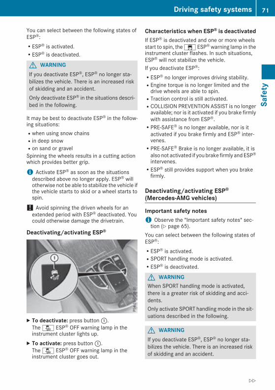
You can select between the following states ofESP®:RESP® is activated.RESP® is deactivated.
G WARNINGIf you deactivate ESP®, ESP® no longer sta-bilizes the vehicle. There is an increased riskof skidding and an accident.Only deactivate ESP® in the situations descri-bed in the following.
It may be best to deactivate ESP® in the follow-ing situations:Rwhen using snow chainsRin deep snowRon sand or gravelSpinning the wheels results in a cutting actionwhich provides better grip.
i Activate ESP® as soon as the situationsdescribed above no longer apply. ESP® willotherwise not be able to stabilize the vehicle ifthe vehicle starts to skid or a wheel starts tospin.
! Avoid spinning the driven wheels for anextended period with ESP® deactivated. Youcould otherwise damage the drivetrain.
Deactivating/activating ESP®
X To deactivate: press button:.The å ESP® OFF warning lamp in theinstrument cluster lights up.
X To activate: press button:.The å ESP® OFF warning lamp in theinstrument cluster goes out.
Characteristics when ESP® is deactivatedIf ESP® is deactivated and one or more wheelsstart to spin, the ÷ ESP® warning lamp in theinstrument cluster flashes. In such situations,ESP® will not stabilize the vehicle.If you deactivate ESP®:RESP® no longer improves driving stability.REngine torque is no longer limited and thedrive wheels are able to spin.RTraction control is still activated.RCOLLISION PREVENTION ASSIST is no longeravailable; nor is it activated if you brake firmlywith assistance from ESP®.RPRE-SAFE® is no longer available, nor is itactivated if you brake firmly and ESP® inter-venes.RPRE-SAFE® Brake is no longer available, it isalso not activated if you brake firmly and ESP®intervenes.RESP® still provides support when you brakefirmly.
Deactivating/activating ESP®(Mercedes‑AMG vehicles)
Important safety notesi Observe the "Important safety notes" sec-tion (Y page 65).
You can select between the following states ofESP®:RESP® is activated.RSPORT handling mode is activated.RESP® is deactivated.
G WARNINGWhen SPORT handling mode is activated,there is a greater risk of skidding and acci-dents.Only activate SPORT handling mode in the sit-uations described in the following.
G WARNINGIf you deactivate ESP®, ESP® no longer sta-bilizes the vehicle. There is an increased riskof skidding and an accident.
Driving safety systems 71
Safety
Z

Only deactivate ESP® in the situations descri-bed in the following.
! Avoid spinning the driven wheels for anextended period with ESP® deactivated. Youcould otherwise damage the drivetrain.
In the following situations, it may be better toactivate SPORT handling mode or deactivateESP®:Rwhen using snow chainsRin deep snowRon sand or gravelRon specially designated roads when the vehi-cle's own oversteering and understeeringcharacteristics are desired
Spinning the wheels results in a cutting actionwhich provides better grip.Driving in SPORT handling mode or withoutESP® requires an extremely qualified and expe-rienced driver.
i Activate ESP® as soon as the situationsdescribed above no longer apply. ESP® willotherwise not be able to stabilize the vehicle ifthe vehicle starts to skid or a wheel starts tospin.
Deactivating/activating ESP®
X To activate SPORT handling mode: brieflypress button:.TheM SPORT handling mode warninglamp in the instrument cluster lights up. TheSPORT handling mode message appears inthe multifunction display.
X To deactivate SPORT handling mode:briefly press button:.TheM SPORT handling mode warninglamp in the instrument cluster goes out.
X To deactivate ESP®: press button: untilthe å ESP® OFF warning lamp lights up inthe instrument cluster.The ÷ OFF message appears in the multi-function display.
X To activate ESP®: briefly press button:.The å ESP® OFF warning lamp in theinstrument cluster goes out. The ÷ ONmessage appears in themultifunction display.
Characteristics of activated SPORT han-dling modeIf SPORT handling mode is activated and one ormore wheels start to spin, the ÷ ESP® warn-ing lamp in the instrument cluster flashes. ESP®only stabilizes the vehicle to a limited degree.When SPORT handling mode is activated:RESP® only improves driving stability to a limi-ted degree.RTraction control is still activated.REngine torque is no longer limited and thedrive wheels are able to spin.RESP® still provides support when you brakefirmly.
Characteristics when ESP® is deactivatedIf ESP® is deactivated and one or more wheelsstart to spin, the ÷ ESP® warning lamp in theinstrument cluster does not flash. In such situa-tions, ESP® will not stabilize the vehicle.If you deactivate ESP®:RESP® no longer improves driving stability.REngine torque is no longer limited and thedrive wheels are able to spin.RTraction control is still activated.RCOLLISION PREVENTION ASSIST is no longeravailable; nor is it activated if you brake firmlywith assistance from ESP®.RPRE-SAFE® is no longer available, nor is itactivated if you brake firmly and ESP® inter-venes.RPRE-SAFE® Brake is no longer available, it isalso not activated if you brake firmly and ESP®intervenes.RESP® still provides support when you brakefirmly.
72 Driving safety systemsSafety
ESP® trailer stabilization
General informationIf your vehicle/trailer combination begins toswerve, ESP® assists you in this situation. ESP®slows the vehicle down by braking and limitingthe engine output until the vehicle/trailer com-bination has stabilized.
Important safety notesG WARNINGIf road and weather conditions are poor,trailer stabilization will not be able to preventthe vehicle/trailer combination from swerv-ing. Trailers with a high center of gravity cantip over before ESP® can detect this. There isa risk of an accident.Always adapt your driving style to the prevail-ing road and weather conditions.
If your vehicle with trailer (vehicle/trailer com-bination) begins to lurch, you can only stabilizethe vehicle/trailer combination by depressingthe brake firmly.ESP® trailer stabilization is active above speedsof approximately 40 mph (65 km/h).ESP® trailer stabilization does not work if ESP®is deactivated or malfunctioning.
Crosswind Assist
General informationStrong crosswind gusts can impair the ability ofyour vehicle to drive straight ahead. The cross-wind driving assistance function integrated inESP® noticeably reduces these impairments.ESP® intervenes automatically according to thedirection and intensity of the crosswinds affect-ing your vehicle.ESP® intervenes with stabilizing braking toassist you in keeping the vehicle in the lane.Crosswind Assist is active at vehicle speedsabove 50 mph (80 km/h) when driving straightahead or cornering gently.
Important safety notesCrosswind Assist does not work if ESP® isswitched off or deactivated because of a mal-function.
EBD (electronic brake force distribu-tion)
General informationEBD monitors and controls the brake pressureon the rear wheels to improve driving stabilitywhile braking.
Important safety notesi Observe the "Important safety notes" sec-tion (Y page 65).
G WARNINGIf EBD is malfunctioning, the rear wheels canlock, e.g. under full braking. This increases therisk of skidding and an accident.You should therefore adapt your driving styleto the different handling characteristics. Havethe brake system checked at a qualified spe-cialist workshop.
Observe information regarding indicator andwarning lamps (Y page 259) as well as displaymessages (Y page 230).
ADAPTIVE BRAKEADAPTIVE BRAKE enhances braking safety andoffers increased braking comfort. In addition tothe braking function, ADAPTIVE BRAKE also hasthe HOLD function (Y page 171) and hill startassist (Y page 136).
PRE-SAFE® Brake
General informationPRE-SAFE® Brake can help you to minimize therisk of a collision with a vehicle ahead or apedestrian, and reduce the effects of such acollision. If PRE-SAFE®Brake has detected a riskof collision, you will be warned visually andacoustically as well as by automatic braking.
i Pay attention to the important safety notesin the "Driving safety systems" section(Y page 65).
PRE‑SAFE® Brake is only available in vehicleswith the Driving Assistance Plus package.
Driving safety systems 73
Safety
Z

For PRE-SAFE®Brake to assist youwhen driving,the radar sensor system and the camera systemmust be switched on and be operational.With the help of the radar sensor system and thecamera system, PRE-SAFE® Brake can detectobstacles that are in front of your vehicle for anextended period of time.In addition, pedestrians in the path of your vehi-cle can be detected.PRE-SAFE® Brake detects pedestrians usingtypical characteristics such as the body con-tours and posture of a person standing upright.
i Observe the restrictions described in the"Important safety notes" section(Y page 74).
Important safety notes
G WARNINGPRE-SAFE® Brake will initially brake your vehi-cle by a partial application of the brakes if adanger of collision is detected. There may bea collision unless you brake yourself. Evenafter subsequent full application of the brakesa collision cannot always be avoided, partic-ularly when approaching at too high a speed.There is a risk of an accident.Always apply the brakes yourself and try totake evasive action, provided it is safe to doso.
In the event of a partial application of the brakes,the vehicle is braked with up to 50% of the fullbraking pressure.
G WARNINGPRE-SAFE® Brake cannot always clearly iden-tify objects and complex traffic conditions.In these cases, PRE-SAFE® Brake may:Rgive an unnecessary warning and thenbrake the vehicleRnot give a warning or interveneThere is a risk of an accident.Always pay particular attention to the trafficsituation and be ready to brake, especially ifPRE-SAFE® Brake warns you. Terminate theintervention in a non-critical driving situation.
G WARNINGPRE-SAFE® Brake cannot always clearly iden-tify people, especially if they are moving. Inthese cases, PRE-SAFE® Brake cannot inter-vene. There is a risk of an accident.Always pay particular attention to the trafficsituation and be ready to brake, especially ifPRE-SAFE® Brake warns you.
In order to maintain the appropriate distance tothe vehicle in front and thus prevent a collision,you must apply the brakes yourself.
G WARNINGPRE-SAFE® Brake does not react:Rto small people, e.g. childrenRto animalsRto oncoming vehiclesRto crossing trafficRwhen corneringAs a result, PRE-SAFE® Brake may neithergive warnings nor intervene in all critical sit-uations. There is a risk of an accident.Always pay careful attention to the traffic sit-uation and be ready to brake.
In the event of snowfall or heavy rain, the rec-ognition can be impaired.Recognition by the radar sensor system is alsoimpaired if:Rthere is dirt on the sensors or anything elsecovering the sensorsRthere is interference by other radar sourcesRthere are strong radar reflections, for exam-ple in parking garagesRa narrow vehicle is traveling in front, e.g. amotorbikeRa vehicle is traveling in front on a different linerelative to the center of your vehicle
Recognition by the camera system is alsoimpaired in the event of:Rdirt on the camera or if the camera is coveredRglare on the camera system, e.g. from the sunbeing low in the sky
74 Driving safety systemsSafety

RdarknessRor if:
- pedestriansmove quickly, e.g. into the pathof the vehicle
- the camera system no longer recognizes apedestrian as a person due to special cloth-ing or other objects
- a pedestrian is concealed by other objects- the typical outline of a pedestrian is notdistinguishable from the background
Following damage to the front end of the vehicle,have the configuration and operation of theradar sensors checked at a qualified specialistworkshop. This also applies to collisions at slowspeeds where there is no visible damage to thefront of the vehicle.Following damage to the windshield, have theconfiguration and operation of the camera sys-tem checked at a qualified specialist workshop.
FunctionX To activate/deactivate: activate or deacti-vate PRE-SAFE® Brake in the on-board com-puter (Y page 221).If the PRE-SAFE® Brake is not activated, theæ symbol appears in themultifunction dis-play.
Starting at a speed of around 4 mph (7 km/h),this function warns you if you are rapidlyapproaching a vehicle in front. An intermittentwarning tone will then sound and the· dis-tance warning lamp will light up in the instru-ment cluster.X Brake immediately to defuse the situation.orX Take evasive action provided it is safe to doso.
PRE-SAFE® Brake can also brake the vehicleautomatically under the following conditions:Rthe driver and front passenger have their seatbelts fastenedRthe vehicle speed is between approximately4 mph (7 km/h) and 124 mph (200 km/h)
At speeds of up to approximately 44 mph(70 km/h), PRE-SAFE® Brake can also detect:Rstationary objects in the path of your vehicle,e.g. stopped or parked vehiclesRpedestrians in the path of your vehicle
i If there is an increased risk of a collision,preventive passenger protection measures(PRE-SAFE®) are triggered (Y page 57).
If the risk of collision with the vehicle in frontremains and you do not brake, take evasiveaction or accelerate significantly, the vehiclemay perform automatic emergency braking, upto the point of full brake application. Automaticemergency braking is not performed until imme-diately prior to an imminent accident.You can prevent the intervention of the PRE-SAFE® Brake at any time by:Rdepressing the accelerator pedal further.Ractivating kickdown.Rreleasing the brake pedalThe braking action of PRE-SAFE® Brake is endedautomatically if:Ryou maneuver to avoid the obstacle.Rthere is no longer a risk of collision.Ran obstacle is no longer detected in front ofyour vehicle.
STEER CONTROL
General informationSTEER CONTROL helps you by transmitting anoticeable steering force to the steering wheelin the direction required for vehicle stabilization.This steering assistance is provided in particularif:Rboth right wheels or both left wheels are on awet or slippery road surface when you brakeRthe vehicle begins to skid
Important safety notesi Observe the "Important safety notes" sec-tion (Y page 65).
No steering support is provided from STEERCONTROL, if:RESP® is deactivatedRESP® is malfunctioningRthe steering is malfunctioningIf ESP® is malfunctioning, you will be assistedfurther by the electrical power steering.
Driving safety systems 75
Safety
Z

Protection against theft
ImmobilizerThe immobilizer prevents your vehicle frombeing started without the correct SmartKey.X To activate with the SmartKey: remove theSmartKey from the ignition lock.
X To activate with KEYLESS-GO start-func-tion or KEYLESS-GO: switch the ignition offand open the driver's door.
X To deactivate: switch on the ignition.When leaving the vehicle, always take theSmartKey with you and lock the vehicle. Anyonecan start the engine if a valid SmartKey has beenleft inside the vehicle.
i The immobilizer is always deactivated whenyou start the engine.In the event that the engine cannot be started(yet the vehicle's battery is charged), the sys-tem is not operational. Contact an authorizedMercedes-Benz Center or call1-800-FOR-MERCedes (in the USA) or1-800-387-0100 (in Canada).
ATA (anti-theft alarm system)
X To arm: lock the vehicle with the SmartKey orKEYLESS-GO.Indicator lamp: flashes. The alarm systemis armed after approximately ten seconds.
X To disarm: unlock the vehicle with the Smart-Key or KEYLESS-GO.
orX Insert the SmartKey into the ignition lock.orX Press the Start/Stop button.The SmartKey must be in the vehicle.
A visual and audible alarm is triggered if thealarm system is armed and you open:Ra doorRthe vehicle with the mechanical keyRthe tailgateRthe hoodX To stop the alarm with the SmartKey:press the% or& button on the Smart-Key.The alarm is stopped.
orX Remove the Start/Stop button from the igni-tion lock (Y page 133).
X Insert the SmartKey into the ignition lock.The alarm is stopped.
X To stop the alarm using KEYLESS-GO:grasp the outside door handle. The SmartKeymust be outside the vehicle.The alarm is stopped.
orX Press the Start/Stop button on the dash-board. The SmartKey must be inside the vehi-cle.The alarm is stopped.
The alarm is not switched off, even if you closethe open door that triggered it, for example.
i If the alarm continues for more than30 seconds, the mbrace emergency call sys-tem automatically notifies the CustomerAssistance Center. This is done either by textmessage or data connection.The emergency call system sends a messageor establishes a data connection providedthat:Ryou have subscribed to thembrace service.Rthe mbrace service has been activatedproperly.Rthe necessary mobile phone network isavailable.
76 Protection against theftSafety

SmartKey
Important safety notes
G WARNINGIf children are left unsupervised in the vehicle,they could:Ropen the doors, thus endangering otherpeople or road users.Rget out and disrupt traffic.Roperate the vehicle's equipment.Additionally, children could set the vehicle inmotion if, for example, they:Rrelease the parking brake.Rshifting the automatic transmission out ofpark position PRStart the engine.There is a risk of an accident and injury.When leaving the vehicle, always take theSmartKeywith you and lock the vehicle. Neverleave children or animals unattended in thevehicle. Always keep the SmartKey out ofreach of children.
G WARNINGIf you attach heavy or large objects to theSmartKey, the SmartKey could be uninten-tionally turned in the ignition lock. This couldcause the engine to be switched off. There is arisk of an accident.Do not attach any heavy or large objects to theSmartKey. Remove any bulky key rings beforeinserting the SmartKey into the ignition lock.
! Keep the SmartKey away from strong mag-netic fields. Otherwise, the remote controlfunction could be affected.Strong magnetic fields can occur in the vicin-ity of powerful electrical installations.
Do not keep the SmartKey:Rwith electronic devices, e.g. a mobile phoneor another SmartKey.Rwith metallic objects, e.g. coins or metal foil.Rinside metallic objects, e.g. a metal case.This can affect the functionality of the Smart-Key.
VehicleswithKEYLESS-GO start function: donot keep the SmartKey in the cargo compart-ment. Otherwise, the SmartKey may not bedetected, e.g. when starting the engine usingthe Start/Stop button.A brief radio connection between the vehicleand the SmartKey determines whether a validSmartKey is in, or in the direct vicinity of, thevehicle. This occurs, for example:Rwhen starting the engineRwhile drivingRwhen using HANDS-FREE ACCESSRwhen the external door handles are touchedRduring convenience closing
SmartKey functions
: & Locks the vehicle; F Opens/closes the tailgate= % Unlocks the vehicleX To unlock centrally: press% button.If you do not open the vehicle within approx-imately 40 seconds of unlocking:Rthe vehicle is locked again.Rprotection against theft is reactivated.
X To lock centrally: press the& button.The SmartKey centrally locks and unlocks thefollowing components:Rthe doorsRthe tailgateRthe fuel filler flapThe turn signals flash once when unlocking andthree times when locking.You can also set an audible signal to confirmthat the vehicle has been locked. The audiblesignal can be activated and deactivated via the
SmartKey 77
Openingandclosing
Z
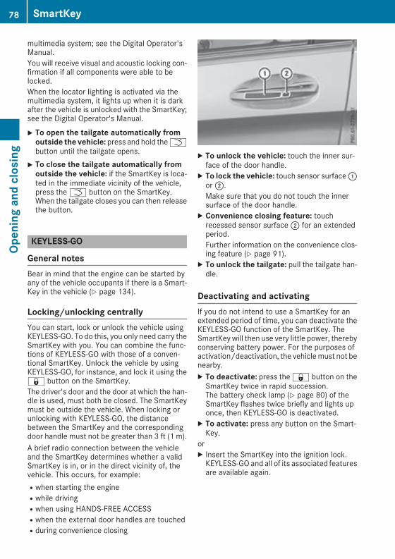
multimedia system; see the Digital Operator'sManual.You will receive visual and acoustic locking con-firmation if all components were able to belocked.When the locator lighting is activated via themultimedia system, it lights up when it is darkafter the vehicle is unlocked with the SmartKey;see the Digital Operator's Manual.
X To open the tailgate automatically fromoutside the vehicle: press and hold theFbutton until the tailgate opens.
X To close the tailgate automatically fromoutside the vehicle: if the SmartKey is loca-ted in the immediate vicinity of the vehicle,press theF button on the SmartKey.When the tailgate closes you can then releasethe button.
KEYLESS-GO
General notesBear in mind that the engine can be started byany of the vehicle occupants if there is a Smart-Key in the vehicle (Y page 134).
Locking/unlocking centrallyYou can start, lock or unlock the vehicle usingKEYLESS-GO. To do this, you only need carry theSmartKey with you. You can combine the func-tions of KEYLESS-GO with those of a conven-tional SmartKey. Unlock the vehicle by usingKEYLESS-GO, for instance, and lock it using the& button on the SmartKey.The driver's door and the door at which the han-dle is used, must both be closed. The SmartKeymust be outside the vehicle. When locking orunlocking with KEYLESS-GO, the distancebetween the SmartKey and the correspondingdoor handle must not be greater than 3 ft (1 m).A brief radio connection between the vehicleand the SmartKey determines whether a validSmartKey is in, or in the direct vicinity of, thevehicle. This occurs, for example:Rwhen starting the engineRwhile drivingRwhen using HANDS-FREE ACCESSRwhen the external door handles are touchedRduring convenience closing
X To unlock the vehicle: touch the inner sur-face of the door handle.
X To lock the vehicle: touch sensor surface:or;.Make sure that you do not touch the innersurface of the door handle.
X Convenience closing feature: touchrecessed sensor surface; for an extendedperiod.Further information on the convenience clos-ing feature (Y page 91).
X To unlock the tailgate: pull the tailgate han-dle.
Deactivating and activatingIf you do not intend to use a SmartKey for anextended period of time, you can deactivate theKEYLESS-GO function of the SmartKey. TheSmartKey will then use very little power, therebyconserving battery power. For the purposes ofactivation/deactivation, the vehiclemust not benearby.X To deactivate: press the& button on theSmartKey twice in rapid succession.The battery check lamp (Y page 80) of theSmartKey flashes twice briefly and lights uponce, then KEYLESS-GO is deactivated.
X To activate: press any button on the Smart-Key.
orX Insert the SmartKey into the ignition lock.KEYLESS-GO and all of its associated featuresare available again.
78 SmartKeyOp
eningandclosing
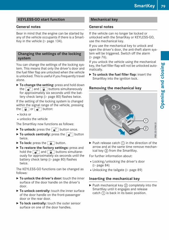
KEYLESS-GO start function
General notesBear in mind that the engine can be started byany of the vehicle occupants if there is a Smart-Key in the vehicle (Y page 134).
Changing the settings of the lockingsystemYou can change the settings of the locking sys-tem. This means that only the driver's door andthe fuel filler flap are unlocked when the vehicleis unlocked. This is useful if you frequently travelalone.X To change the setting: press and hold downthe% and& buttons simultaneouslyfor approximately six seconds until the bat-tery check lamp (Y page 80) flashes twice.
If the setting of the locking system is changedwithin the signal range of the vehicle, pressingthe& or% button:Rlocks orRunlocks the vehicleThe SmartKey now functions as follows:X To unlock: press the% button once.X To unlock centrally: press the% buttontwice.
X To lock: press the& button.X To restore the factory settings: press andhold the% and& buttons simultane-ously for approximately six seconds until thebattery check lamp (Y page 80) flashestwice.
The KEYLESS-GO functions can be changed asfollows:X To unlock the driver's door: touch the innersurface of the door handle on the driver'sdoor.
X To unlock centrally: touch the inner surfaceof the door handle on the front-passengerdoor or the rear door.
X To lock centrally: touch the outer sensorsurface on one of the door handles.
Mechanical key
General notesIf the vehicle can no longer be locked orunlocked with the SmartKey or KEYLESS-GO,use the mechanical key.If you use the mechanical key to unlock andopen the driver's door, the anti-theft alarm sys-tem will be triggered. Switch off the alarm(Y page 76).If you unlock the vehicle using the mechanicalkey, the fuel filler flap will not be unlocked auto-matically.X To unlock the fuel filler flap: insert theSmartKey into the ignition lock.
Removing the mechanical key
X Push release catch: in the direction of thearrow and at the same time remove mechan-ical key; from the SmartKey.
For further information about:RLocking/unlocking the driver's door(Y page 84)RUnlocking the tailgate (Y page 89)
Inserting the mechanical keyX Push mechanical key; completely into theSmartKey until it engages and releasecatch: is back in its basic position.
SmartKey 79
Openingandclosing
Z

SmartKey battery
Important safety notes
G WARNINGBatteries contain toxic and corrosive substan-ces. If batteries are swallowed, it can result insevere health problems. There is a risk of fatalinjury.Keep batteries out of the reach of children. Ifa battery is swallowed, seekmedical attentionimmediately.
H Environmental noteBatteries contain dangeroussubstances. It is against thelaw to dispose of them withthe household rubbish. Theymust be collected separatelyand recycled to protect theenvironment.Dispose of batteries in anenvironmentally friendlymanner. Take dischargedbatteries to a qualified spe-cialist workshop or a specialcollection point for used bat-teries.
The SmartKey batteries contain perchloratematerial, which may require special handlingand regard for the environment. National guide-lines must be observed during disposal. In Cal-ifornia, see www.dtsc.ca.gov/HazardousWaste/Perchlorate/index.cfm.Mercedes-Benz recommends that you have thebatteries replaced at a qualified specialist work-shop.
Checking the battery
X Press the& or% button.The battery is working properly if batterycheck lamp: lights up briefly.The battery is discharged if battery checklamp: does not light up briefly.
X Change the battery (Y page 80).If the SmartKey battery is checked within thesignal reception range of the vehicle, pressingthe& or% button:Rlocks orRunlocks the vehicle
i You can get a battery at any qualified spe-cialist workshop.
Replacing the batteryYou require a CR 2025 3 V cell battery.X Take the mechanical key out of the SmartKey(Y page 79).
X Press mechanical key; into the SmartKeyopening in the direction of the arrow until bat-tery compartment cover: opens. Do nothold battery compartment cover: closedwhile doing so.
X Remove battery compartment cover:.
80 SmartKeyOp
eningandclosing

X Repeatedly tap the SmartKey against yourpalm until battery= falls out.
X Insert the new battery with the positive ter-minal facing upwards. Use a lint-free cloth todo so.
X Make sure that the surface of the battery isfree of lint, grease and other contaminants.
X Insert the front tabs of battery compartmentcover: into the housing first and then pressto close it.
X Insert mechanical key; into the SmartKey(Y page 79).
X Check the function of all SmartKey buttons onthe vehicle.
Problems with the SmartKey
Problem Possible causes/consequences andM Solutions
You can no longer lock orunlock the vehicle usingthe SmartKey.
The SmartKey battery is discharged or nearly discharged.X Check the SmartKey battery (Y page 80) and replace it if necessary(Y page 80).
If this does not work:X Lock or unlock the vehicle using the mechanical key (Y page 84).
There is interference from a powerful source of radio waves.X Lock or unlock the vehicle using the mechanical key (Y page 84).
The SmartKey is faulty.X Lock or unlock the vehicle using the mechanical key (Y page 84).X Have the SmartKey checked at a qualified specialist workshop.
You can no longer lock orunlock the vehicle usingKEYLESS-GO.
KEYLESS-GO was deactivated.X Reactivate KEYLESS-GO (Y page 78).
The SmartKey battery is discharged or nearly discharged.X Check the SmartKey battery (Y page 80) and replace it if necessary(Y page 80).
If this does not work:X Lock or unlock the vehicle using the mechanical key (Y page 84).
There is interference from a powerful source of radio waves.X Lock or unlock the vehicle using the mechanical key (Y page 84).
SmartKey 81
Openingandclosing
Z

Problem Possible causes/consequences andM Solutions
KEYLESS-GO is malfunctioning.X Lock/unlock the vehicle using the remote control function of theSmartKey.
X Have the vehicle and SmartKey checked at a qualified specialistworkshop.
If the vehicle can also not be locked/unlocked using the remote con-trol function:X Lock or unlock the vehicle using the mechanical key (Y page 84).X Have the vehicle and SmartKey checked at a qualified specialistworkshop.
The engine cannot bestarted using the Smart-Key.
The on-board voltage is too low.X Switch off non-essential consumers, e.g. seat heating or interiorlighting, and try to start the engine again.
If this does not work:X Check the starter battery and charge it if necessary (Y page 327).orX Jump-start the vehicle (Y page 328).orX Consult a qualified specialist workshop.
The engine cannot bestarted using the Start/Stop button. The Smart-Key is in the vehicle.
The vehicle is locked.X Unlock the vehicle and try to start the vehicle again.
The SmartKey battery is discharged or nearly discharged.X Check the SmartKey battery (Y page 80) and replace it if necessary(Y page 80).
If this does not work:X Start your vehicle with the SmartKey in the ignition lock.
There is interference from a powerful source of radio waves.X Start your vehicle with the SmartKey in the ignition lock.
You have lost a Smart-Key.
X Have the SmartKey deactivated at a qualified specialist workshop.X Report the loss immediately to the vehicle insurers.X If necessary, have the locks changed as well.
You have lost themechanical key.
X Report the loss immediately to the vehicle insurers.X If necessary, have the locks changed as well.
82 SmartKeyOp
eningandclosing

Doors
Important safety notes
G WARNINGIf children are left unsupervised in the vehicle,they could:Ropen the doors, thus endangering otherpeople or road users.Rget out and disrupt traffic.Roperate the vehicle's equipment.Additionally, children could set the vehicle inmotion if, for example, they:Rrelease the parking brake.Rshifting the automatic transmission out ofpark position PRStart the engine.There is a risk of an accident and injury.When leaving the vehicle, always take theSmartKeywith you and lock the vehicle. Neverleave children or animals unattended in thevehicle. Always keep the SmartKey out ofreach of children.
Unlocking and opening doors fromthe insideYou can open a door from inside the vehicleeven if it has been locked. You can only open therear doors from inside the vehicle if they are notsecured by the child-proof locks (Y page 64). Ifthe vehicle has been locked with the SmartKeyor with KEYLESS-GO, opening a door from theinside will trigger the anti-theft alarm system.Switch off the alarm (Y page 76).
X To unlock and open a front door: pull doorhandle;.If the door is locked, locking knob: pops up.The door is unlocked and opens.
X To unlock a rear door: pull rear door handle.The locking knob on the rear door pops up andthe rear door unlocks.
X To open a rear door: pull rear door handleagain.The rear door opens.
Centrally locking and unlocking thevehicle from the insideYou can centrally lock and unlock the vehiclefrom the inside. The switches are on the driver’sdoor.
X To unlock: press button:.X To lock: press button;.When the front-passenger door is closed, thevehicle is locked.
Meanwhile, the fuel filler flap will not be lockedor unlocked.You cannot unlock the vehicle centrally from theinside if the vehicle has been locked with theSmartKey or KEYLESS-GO.If the vehicle has been lockedwith the SmartKeyor with KEYLESS-GO, opening a door from theinside will trigger the anti-theft alarm system.Switch off the alarm (Y page 76).If a locked door is opened from the inside, theprevious unlock status of the vehicle will betaken into consideration if:Rthe vehicle was locked using the locking but-ton for the central locking, orRlocked automatically
Doors 83
Openingandclosing
Z

The vehicle will be fully unlocked if it had previ-ously been fully unlocked. If only the driver'sdoor had been previously unlocked, only thedoor which has been opened from the inside isunlocked.
Automatic locking feature
X To deactivate: press and hold button: forapproximately five seconds until a tonesounds.
X To activate: press and hold button; forapproximately five seconds until a tonesounds.
If you press one of the two buttons and do nothear a tone, the relevant setting has alreadybeen selected.The vehicle is locked automatically when theignition is switched on and the wheels are turn-ing.You could therefore be locked out if:Rthe vehicle is being pushed.Rthe vehicle is being towed.Rthe vehicle is being tested on a dynamometer.You can activate and deactivate the automaticlocking mechanism via the multimedia system(see the Digital Operator's Manual).
Locking/unlocking the driver's doorwith the mechanical keyi If youwant to centrally lock the vehicle usingthe mechanical key, begin by pressing thelocking button for the interior locking mech-anism while the driver's door is open. Thenlock the driver's door using the mechanicalkey.
X Insert the mechanical key into opening: inthe protective cap.
X Pull and hold the door handle.X Pull the protective cap on the mechanical keyas straight as possible away from the vehicleuntil it releases.
X Release the door handle.
X To lock: turn themechanical key clockwise asfar as it will go to position1.
X To unlock: turn the mechanical key counter-clockwise as far as it will go to position1.
If you use the mechanical key to unlock andopen the driver's door, the anti-theft alarm sys-tem will be triggered. Switch off the alarm(Y page 76).
Cargo compartment
Important safety notes
G WARNINGCombustion engines emit poisonous exhaustgases such as carbonmonoxide. If the tailgateis open when the engine is running, particu-larly if the vehicle is moving, exhaust fumes
84 Cargo compartmentOp
eningandclosing

could enter the passenger compartment.There is a risk of poisoning.Turn off the engine before opening the tail-gate. Never drive with the tailgate open.
G WARNINGIf objects, luggage or loads are not secured ornot secured sufficiently, they could slip, tipover or be flung around and thereby hit vehicleoccupants. There is a risk of injury, particu-larly in the event of sudden braking or a sud-den change in direction.Always store objects so that they cannot beflung around. Secure objects, luggage orloads against slipping or tipping before thejourney.
! The tailgate swings upwards and to the rearwhen opened. Therefore, make sure thatthere is sufficient clearance above and behindthe tailgate.
The opening dimensions of the tailgate can befound in the "Vehicle data" section(Y page 370).You can limit the opening angle of the tailgate(Y page 89).Do not leave the SmartKey in the cargo com-partment. You could otherwise lock yourselfout.You should preferably place luggage or loads inthe cargo compartment. Observe the loadingguidelines (Y page 278).
Tailgate obstruction detection withreversing featureVehicles with remote tailgate closing:The tailgate is equippedwith automatic obstruc-tion detection with reversing feature. If a solidobject blocks or restricts the tailgatewhen auto-matically opening, this procedure is stopped. If asolid object blocks or restricts the tailgate whenautomatically closing, the tailgate automaticallyopens again slightly. The automatic obstructiondetection with reversing feature is only an aid. Itis not a substitute for your attentiveness whenopening and closing the tailgate.
G WARNINGThe reversing feature does not respond:Rto soft, light and thin objects, e.g. fingersRover the lastÓ in (8 mm) of the closingmovement
The reversing feature cannot prevent some-one from becoming trapped in these situa-tions in particular. There is a risk of injury.Make sure that no body parts are in closeproximity during the closing procedure.If somebody becomes trapped:Rpress theF button on the SmartKey, orRpull or press the remote operating switchon the driver's door orRpress the closing or locking button on thetailgate orRpull the handle on the tailgate
Vehicles with HANDS-FREE ACCESS:It is also possible to stop the closing process byperforming a kicking movement under the rearbumper.
Opening and closing manually
Opening
X Press theF button on the SmartKey.orX Pull handle:.The tailgate opens.
Cargo compartment 85
Openingandclosing
Z

Closing
X Pull the tailgate down using recesses: andpush it closed.
X Lock the vehicle if necessary with the&button on the SmartKey or with KEYLESS-GO(Y page 78).
Opening/closing automatically fromoutside
Important safety notes
G WARNINGCombustion engines emit poisonous exhaustgases such as carbonmonoxide. If the tailgateis open when the engine is running, particu-larly if the vehicle is moving, exhaust fumescould enter the passenger compartment.There is a risk of poisoning.Turn off the engine before opening the tail-gate. Never drive with the tailgate open.
G WARNINGParts of the body could become trapped dur-ing automatic closing of the tailgate. More-over, people, e.g. children, may be standing inthe closing area or may enter the closing areaduring the closing process. There is a risk ofinjury.Make sure that nobody is in the vicinity of theclosing area during the closing process.
Use one of the following options to stop theclosing process:Rpress theF button on the SmartKey.Rpull or press the remote operating switchon the driver's door.Rpress the closing or locking button on thetailgate.Rpull the handle on the tailgate
Vehicles with HANDS-FREE ACCESS:It is also possible to stop the closing process byperforming a kicking movement under the rearbumper.
! The tailgate swings upwards and to the rearwhen opened. Therefore, make sure thatthere is sufficient clearance above and behindthe tailgate.
Two warning tones sound while the tailgate isopening or closing.The opening dimensions of the tailgate can befound in the "Vehicle data" section(Y page 370).
Opening automaticallyYou can open the tailgate automatically with theSmartKey or the handle in the tailgate.X Press and hold theF button on the Smart-Key until the tailgate opens.
orX If the tailgate is unlocked, pull the handle andlet it go again immediately.
orX With the tailgate stopped in an intermediateposition, pull the tailgate up.You can release the tailgate as soon as thetailgate starts to open.
86 Cargo compartmentOp
eningandclosing

Closing automatically
: Closing button; Locking buttonX Press closing button: in the tailgate.orX Pull the tailgate down slightly.You can release the tailgate as soon as thetailgate starts to close.
When the driver's door is closed, you can simul-taneously close the tailgate and lock the vehicle.The KEYLESS-GO key must be in the rear detec-tion range of the vehicle.X Press locking button; in the tailgate.If KEYLESS-GO detects a SmartKey outsidethe vehicle, the tailgate closes. The vehicle islocked.
orX Vehicles with EASY-PACK tailgate andKEYLESS-GO or KEYLESS-GO start func-tion: if the SmartKey is located in the imme-diate vicinity of the vehicle, press theFbutton on the SmartKey.You can release the button as soon as thetailgate starts to close.
If KEYLESS-GO detects a SmartKey in the cargocompartment, the tailgate is unlocked againafter closing.If KEYLESS-GO detects a second SmartKey out-side the vehicle, the tailgate remains locked.If KEYLESS-GO detects a SmartKey in the cargocompartment before the closing procedurestarts, the tailgate remains open.
HANDS-FREE ACCESS
General notesWith KEYLESS-GO and HANDS-FREE ACCESS,you can open or close the tailgate or stop theprocedure without using your hands. This is use-ful if you have your hands full. To do this, makea kickingmovement under the bumperwith yourfoot.Observe the following points:RCarry your KEYLESS-GO key about your per-son. The KEYLESS-GO key must be in the reardetection range of the vehicle.RWhen making the kicking movement, makesure that you are standing firmly on theground and that there is sufficient clearanceto the rear of the vehicle. You could otherwiselose your balance, for example on ice.
RAlways ensure that you only make the kickingmovement within the detection range of sen-sors:.RStand at least 12 in (30 cm) away from therear area while doing so.RDo not come into contact with the bumperwhile making the kicking movement. Other-wise, the sensors may not function correctly.RHANDS-FREE ACCESS does not functionwhen the engine is started.RDirt caused by road salt or snow around sen-sors: may restrict functionality.Using the HANDS-FREE ACCESS with a pros-thetic leg may restrict functionality.RIf a KEYLESS-GO key is within the rear detec-tion range of KEYLESS-GO, HANDS-FREEACCESS could be triggered. The tailgate
Cargo compartment 87
Openingandclosing
Z

could thus be opened or closed unintention-ally, for example, if you:- install or remove the ball coupling.- couple or uncouple a trailer.- install or remove a rear-mounted bicyclerack.
- load/unload bicycles on/from a rear-mounted bicycle rack.
- sit on the edge of the cargo compartment.- set something down or lift something upbehind the vehicle.
- polish the rear of the vehicle.Do not carry the KEYLESS-GO key about yourperson in these situations or in situations sim-ilar to these. This will prevent unintentionalopening or closing of the tailgate.
Important safety notes
G WARNINGThe vehicle's exhaust systemmay be very hot.You could burn yourself by touching theexhaust system if you use HANDS-FREEACCESS. There is a risk of injury. Alwaysensure that you only make the kicking move-ment within the detection range of sensors.
! If the SmartKey is within the rear detectionrange of KEYLESS-GO, the following situa-tions, for example, could lead to the uninten-tional opening of the tailgate:Rusing a car washRusing a power washerMake sure that the SmartKey is at least 10 ft(3 m) away from the vehicle.
Operation
X To open or close: kick into sensor detectionrange: under the bumper with your foot.Two warning tones sound while the tailgate isopening or closing.
X If the tailgate does not open or close afterseveral attempts: wait at least ten secondsthen kick under the bumper once again.
If you hold your foot under the bumper for toolong, the tailgate does not open or close. Repeatthe leg movement more quickly if this occurs.To stop the opening or closing procedure, youhave the following options:RKick with your foot into sensor detectionrange: under the bumper.RPull the handle on the outside of the tailgate.RPress the closing button on the tailgate.RPress theF button on the SmartKeyIf the tailgate closing procedure has been stop-ped:RMove your foot under the bumper again andthe tailgate will open.
If the tailgate opening procedure has been stop-ped:RKick with your foot under the bumper againand the tailgate will close.
Opening/closing automatically frominside
Important safety notes
G WARNINGCombustion engines emit poisonous exhaustgases such as carbonmonoxide. If the tailgateis open when the engine is running, particu-larly if the vehicle is moving, exhaust fumescould enter the passenger compartment.There is a risk of poisoning.Turn off the engine before opening the tail-gate. Never drive with the tailgate open.
G WARNINGParts of the body could become trapped dur-ing automatic closing of the tailgate. In addi-tion, people may be standing in the closingarea or may enter the closing area, e.g. chil-
88 Cargo compartmentOp
eningandclosing

dren, during the closing procedure. There is arisk of injury.Make sure that nobody is in the vicinity of theclosing area during the closing process.Release the remote operating switch imme-diately if somebody becomes trapped. To re-open the tailgate pull on the remote operatingswitch.
Vehicles with HANDS-FREE ACCESS:It is also possible to stop the closing process byperforming a kicking movement under the rearbumper.
! The tailgate swings upwards and to the rearwhen opened. Therefore, make sure thatthere is sufficient clearance above and behindthe tailgate.
Two warning tones sound while the tailgate isopening or closing.The opening dimensions of the tailgate can befound in the "Vehicle data" section(Y page 370).
Opening and closing
X To open: pull remote operating switch: forthe tailgate until the tailgate opens.
X To close: turn the SmartKey to position1 or2 in the ignition lock.
X Press and hold remote operating switch fortailgate: until the tailgate is completelyclosed.
When the vehicle is stationary, you can close thetailgate from the driver's seat. When the vehicleis also unlocked, you can also open the tailgatefrom inside.
Limiting the opening angle of the tail-gate
General notes! Make sure there is sufficient clearance toopen the tailgate fully when setting the open-ing angle. The tailgate could otherwise bedamaged. Ideally, set the opening angle out-side.
You can limit the opening angle of the tailgate.This is possible in the top half of its openingrange, up to approximately 8 in (20 cm) beforethe stop.To open the tailgate fully, pull the handle on theoutside of the tailgate again after it has stoppedautomatically. This does not delete the storedposition.
ActivatingX To open the tailgate: pull the handle on thetailgate.
X To stop the opening procedure at thedesired position: press the closing button inthe tailgate or pull the handle on the outsideof the tailgate again.
X To store the position: press and hold theclosing button in the tailgate until you hear ashort tone.The opening angle limiter is activated. Thetailgate will now stop in the stored positionwhen opening.
DeactivatingX Press and hold the closing button on the tail-gate until two short tones sound.
Unlocking the tailgate using themechanical key
General notesUse the mechanical key if the tailgate can nolonger be unlocked:Rusing the SmartKeyRusing HANDS-FREE ACCESSRusing the remote operating switch on the doorcontrol panel
Cargo compartment 89
Openingandclosing
Z

! The tailgate swings upwards and to the rearwhen opened. Therefore, make sure thatthere is sufficient clearance above and behindthe tailgate.
Unlocking
X Remove cargo compartment cover(Y page 285).
X Fold the rear seat backrest forward(Y page 281).
X Insert mechanical key; into opening: inthe paneling and push it in.
X Open the tailgate.When you lock the vehicle, the cargo compart-ment is also locked again.
Side windows
Important safety notes
G WARNINGWhile opening the side windows, body partscould become trapped between the side win-dow and the door frame as the side windowmoves. There is a risk of injury.Make sure that nobody touches the side win-dow during the opening procedure. If some-body becomes trapped, release the switch orpull the switch to close the sidewindow again.
G WARNINGWhile closing the side windows, body parts inthe closing area could become trapped. Thereis a risk of injury.When closing make sure that no parts of thebody are in the closing area. If somebody
becomes trapped, release the switch or pressthe switch to open the side window again.
G WARNINGIf children operate the side windows theycould become trapped, particularly if they areleft unsupervised. There is a risk of injury.Activate the override feature for the rear sidewindows. When leaving the vehicle, alwaystake the SmartKey with you and lock the vehi-cle. Never leave children unsupervised in thevehicle.
Side window reversing featureThe side windows are equipped with an auto-matic reversing feature. If a solid object blocksor restricts a side window from travelingupwards during the automatic closing process,the sidewindowopens again automatically. Dur-ing themanual closing process, the side windowonly opens again automatically after the corre-sponding switch is released. The automaticreversing feature is only an aid and is no substi-tute for your attention when closing a side win-dow.
G WARNINGThe reversing feature does not react:Rto soft, light and thin objects, e.g. small fin-gersRwhile resettingThis means that the reversing feature cannotprevent someone being trapped in these sit-uations. There is a risk of injury.Make sure that no body parts are in closeproximity during the closing procedure. Ifsomeone becomes trapped, press the switchto open the side window again.
Opening and closing the side win-dowsThe switches for all side windows are located onthe driver's door. There is also a switch on eachdoor for the corresponding side window.
90 Side windowsOp
eningandclosing

The switches on the driver's door take prece-dence.
: Front left; Front right= Rear right? Rear leftX Turn the SmartKey to position1 or2 in theignition lock.
X To open manually: press and hold the cor-responding switch.
X To open fully: press the switch beyond thepressure point and release it.Automatic operation is started.
X To close manually: pull the correspondingswitch and hold it.
X To close fully: pull the switch beyond thepressure point and release it.Automatic operation is started.
X To interrupt automatic operation: press/pull the corresponding switch again.
If you press the switch beyond the pressurepoint and release, automatic operation is star-ted in the corresponding direction. You can stopautomatic operation by pressing/pulling theswitch again.You can continue to operate the side windowsafter you switch off the engine or remove theSmartKey. This function remains active for fiveminutes or until you open a front door.When the override feature for the side windowsis activated, the side windows cannot be oper-ated from the rear (Y page 64).Information on opening and closing the rollersunblinds on the rear side windows(Y page 291).
Convenience opening
General notesIf the SmartKey is in close proximity to the vehi-cle, the convenience opening function is availa-ble.Vehicles with KEYLESS-GO or KEYLESS-GOstart function: you can ventilate the vehiclebefore you start driving.To do this, the SmartKey is used to carry out thefollowing functions simultaneously:Runlock the vehicleRopen the side windowsRopen the panorama roof with power tilt/slid-ing panel and the roller sunblindRswitch on the seat ventilation for the driver'sseat
The "convenience opening" feature is also avail-able when the vehicle is unlocked.
Convenience openingX Press and hold the% button on the Smart-Key until the side windows and the panoramaroof with power tilt/sliding panel are in thedesired position.If the roller sunblinds of the panorama roofwith power tilt/sliding panel are closed, theroller sunblinds are opened first.
X Press and hold the% button again until thepanorama roof with power tilt/sliding panel isin the desired position.
X To interrupt convenience opening: releasethe% button.
Convenience closing feature
Important safety notes
G WARNINGWhen the convenience closing feature is oper-ating, parts of the body could become trappedin the closing area of the side window and thesliding sunroof. There is a risk of injury.Observe the complete closing procedurewhen the convenience closing feature is oper-ating. Make sure that no body parts are inclose proximity during the closing procedure.
Side windows 91
Openingandclosing
Z

Vehicles with KEYLESS-GO or KEYLESS-GOstart function: if the SmartKey is in close prox-imity to the vehicle, the convenience closingfunction is available.When you lock the vehicle, you can simultane-ously:Rclose the side windowsRclose the panorama roof with power tilt/slid-ing panel
On vehicles with a panorama roof with powertilt/sliding panel, you can then close the rollersunblinds.Notes on the automatic reversing feature for:Rthe side window (Y page 90)Rthe panorama roof with power tilt/slidingpanel (Y page 94)
Using the SmartKeyX Press and hold the& button until the sidewindows and the panorama roof with powertilt/sliding panel are fully closed.
X Make sure that all the side windows and thepanorama roof with power tilt/sliding panelare closed.
X Press and hold the& button again until theroller sunblinds of the panorama roof withpower tilt/sliding panel are closed.
X To interrupt convenience closing: releasethe& button.
Using KEYLESS-GOThe driver's door and the door at which the han-dle is used, must both be closed. The SmartKeymust be outside the vehicle. The gap betweenthe SmartKey and the corresponding door han-dle should not be greater than 3 ft (1 m).
X Touch recessed sensor surface: on thedoor handle until the side windows and thepanorama roof with power tilt/sliding panelare fully closed.Make sure you touch only recessed sensorsurface:.
X Make sure that all the side windows and thepanorama roof with power tilt/sliding panelare closed.
X Touch recessed sensor surface: on thedoor handle again until the roller sunblinds ofthe panorama roof with power tilt/slidingpanel close.
X To interrupt convenience closing: releaserecessed sensor surface: on the door han-dle.
Resetting the side windowsIf a side window can no longer be closed fully,you must reset it.X Close all the doors.X Turn the SmartKey to position1 or2 in theignition lock.
X Pull the corresponding switch on the doorcontrol panel until the side window is com-pletely closed (Y page 90).
X Hold the switch for an additional second.If the side window opens again slightly:X Immediately pull the corresponding switch onthe door control panel until the side window iscompletely closed (Y page 90).
X Hold the switch for an additional second.X If the respective side window remains closedafter the button is released, then it has beenset correctly. If this is not the case, repeat thesteps above.
92 Side windowsOp
eningandclosing
Problems with the side windows
G WARNINGIf you close a side window again immediately after it has been blocked or reset, the side windowcloses with increased or maximum force. The reversing feature is then not active. Parts of thebody could be trapped in the closing area in the process. This poses an increased risk of injury oreven fatal injury.Make sure that no parts of the body are in the closing area. To stop the closing process, releasethe switch or push the switch again to reopen the side window.
Problem Possible causes/consequences andM Solutions
A side window cannot beclosed because it isblocked by objects, e.g.leaves in the windowguide.
X Remove the objects.X Close the side window.
A side window cannot beclosed and you cannotsee the cause.
If a side window is obstructed during closing and reopens againslightly:X Immediately after the window blocks, pull the corresponding switchagain until the side window has closed.The side window is closed with increased force.
If a side window is obstructed again during closing and reopens againslightly:X Immediately after the window blocks, pull the corresponding switchagain until the side window has closed.The side windows are closed without the automatic reversing fea-ture.
Panorama roofwith power tilt/slidingpanel
Important safety notesIn the following section, the term "sliding sun-roof" refers to the panorama roof with powertilt/sliding panel.
G WARNINGWhile opening and closing the sliding sunroof,body parts in close proximity could becometrapped. There is a risk of injury.Make sure that no body parts are in closeproximity during the opening and closing pro-cedures.
If somebody becomes trapped:Rrelease the switch immediately, orRduring automatic operation, push theswitch briefly in any direction
The opening or closing procedure will be stop-ped.
G WARNINGIf children operate the sliding sunroof theycould become trapped, particularly if they areleft unsupervised. There is a risk of injury.When leaving the vehicle, always take theSmartKeywith you and lock the vehicle. Neverleave children unsupervised in the vehicle.
Panorama roof with power tilt/sliding panel 93
Openingandclosing
Z

G WARNINGAt high speeds the raised sliding sunroof auto-matically lowers slightly at the rear. This couldtrap you or other persons. There is a risk ofinjury. Make sure that nobody reaches intothe sweep of the sliding sunroof whilst thevehicle is in motion.If somebody becomes trapped, immediatelypull back the sliding sunroof switch. The slid-ing sunroof lifts during opening.
! Only open the sliding sunroof if it is free ofsnow and ice. Otherwise, malfunctions mayoccur.Do not allow anything to protrude from thesliding sunroof. Otherwise, the seals could bedamaged.
! The weather can change abruptly. It couldstart to rain or snow. Make sure that the slid-ing sunroof is closed when you leave the vehi-cle. The vehicle electronics can be damaged ifwater enters the vehicle interior.
Resonance noises can occur in addition to theusual airflow noises when the sliding sunroof isopen. They are caused by minor pressure fluc-tuations in the vehicle interior. Change the posi-tion of the sliding sunroof or open a side windowslightly to reduce or eliminate these noises.
Sliding sunroof reversing featureIn the following section, the term "sliding sun-roof" refers to the panorama roof with powertilt/sliding panel.The sliding sunroof is equipped with an auto-matic reversing feature. If a solid object blocksor restricts the sliding sunroof during the closingprocess, the sliding sunroof opens again auto-matically. The automatic reversing feature isonly an aid and is no substitute for your attentionwhen closing the sliding roof.
G WARNINGThe reversing feature does not react:Rto soft, light and thin objects, e.g. small fin-gersRover the last 1/6 in (4 mm) of the closingmovement
Rduring resettingRwhen closing the sliding sunroof againman-ually immediately after automatic reversing
This means that the reversing feature cannotprevent someone being trapped in these sit-uations. There is a risk of injury.Make sure that no body parts are in closeproximity during the closing procedure.If somebody becomes trapped:Rrelease the switch immediately, orRpress the switch in any direction during theautomatic closing process
The closing process is stopped.
Operating the panorama roof withpower tilt/sliding panel
Opening and closing
: To raise; To open= To close/lowerThe panorama roof with power tilt/sliding panelcan only be operated when the roller sunblind isopen.X Turn the SmartKey to position1 or2 in theignition lock.
X Press or pull the3 switch in the corre-sponding direction.
If you press or pull the3 switch beyond thepressure point, automatic operation is started inthe corresponding direction. You can stop auto-matic operation by pressing or pulling again.If the panorama roof with power tilt/slidingpanel is raised at the rear, it automatically low-ers slightly at higher speeds. The noise level in
94 Panorama roof with power tilt/sliding panelOp
eningandclosing

the vehicle interior is reduced as a result. At lowspeeds it raises again automatically.You can also temporarily deactivate automaticlowering. To do so, press the3 switch. Thepanorama roof with power tilt/sliding panel rai-ses again automatically.You can continue to operate the panorama roofwith power tilt/sliding panel after you switch offthe engine or remove the SmartKey. This func-tion remains active for five minutes or until youopen a front door.When a roof carrier is mounted the panoramaroof with power tilt/sliding panel cannot beopened. The panorama roof with power tilt/slid-ing panel can still be raised to allow ventilationof the vehicle interior. If the panorama roof withpower tilt/sliding panel makes contact with aroof carrier approved by Mercedes-Benz, thesunroof will lower slightly but remain raised atthe rear.
Rain-closing featureThe raised panorama roofwith power tilt/slidingpanel automatically lowers when driving if itstarts to rain. The sliding sunroof is lowereddepending on:Rthe road speedRthe intensity of the rainYou can manually cancel the automatic closingprocedure. Press or pull the3 switch in anydirection.To raise the panorama roof with power tilt/slid-ing panel again, press the3 switch in direc-tion:.The rain-closing feature is then deactivated untilyou:Rpress or pull the3 switch in any directionorRturn the SmartKey to another position in theignition lock (Y page 132)
Operating the roller sunblinds for thepanorama roof with power tilt/slidingpanel
Important safety notes
G WARNINGParts of the body could become trappedbetween the roller sunblind and frame or slid-ing sunroof during automatic opening or clos-ing. There is a risk of injury.When opening or closing, make sure that nobody parts are in the sweep of the roller sun-blind.If somebody becomes trapped:Rrelease the switch immediately, orRduring automatic operation, push theswitch briefly in any direction
The opening or closing procedure will be stop-ped.
The roller sunblinds shield the vehicle interiorfrom sunlight. The roller sunblinds can only beopened and closed when the panorama roofwith power tilt/sliding panel is closed.
Roller sunblind reversing featureThe roller sunblinds are equipped with an auto-matic reversing feature. If a solid object blocksor restricts a roller sunblind during the closingprocess, the roller sunblind opens again auto-matically. However, the automatic reversingfeature is only an aid and is not a substitute ofyour attentiveness when closing the roller sun-blind.
G WARNINGThe reversing feature does not react in par-ticular to soft, light and thin objects, e.g. smallfingers. This means that the reversing featurecannot prevent someone being trapped inthese situations. There is a risk of injury.When closing the roller sunblind, make surethat no body parts are in the sweep area.
Panorama roof with power tilt/sliding panel 95
Openingandclosing
Z

If somebody becomes trapped:Rrelease the switch immediately, orRpress the switch in any direction during theautomatic closing process
The closing process is stopped.
Opening and closing the roller sun-blinds
: Opens; Opens= ClosesYou can only close the roller sunblinds when thepanorama roof with power tilt/sliding panel isclosed.X Turn the SmartKey to position1 or2 in theignition lock.
X Press the3 switch in direction:.Both roller sunblinds open, then the pano-rama roof with power tilt/sliding panel israised.
X Pull the3 switch in direction;.The sunblinds open.
X Pull the3 switch in direction=.The roller sunblinds closewhen the panoramaroof with power tilt/sliding panel is closed.
If you press or pull the3 switch beyond thepressure point, automatic operation is started inthe corresponding direction. You can stop auto-matic operation by pressing or pulling again.
Resetting the panorama roof withpower tilt/sliding panel or the frontroller sunblind! If the panorama roof with power tilt/slidingpanel and the roller sunblinds cannot be fullyopened or closed after resetting, contact aqualified specialist workshop.
Reset the panorama roof with power tilt/slidingpanel or the roller sunblinds if the panoramaroof with power tilt/sliding panel or the frontroller sunblind does not move smoothly.X Turn the SmartKey to position1 or2 in theignition lock.
X Pull the3 switch repeatedly to the point ofresistance in the direction of arrow: untilthe panorama roof with power tilt/slidingpanel is fully closed.
X Keep the3 switch pulled for an additionalsecond.
X Pull the3 switch several times in thedirection of arrow: until the roller sunblindsare closed.
X Keep the3 switch pulled for an additionalsecond.
X Make sure that the panorama roof with powertilt/sliding panel and the roller sunblinds canbe fully opened and closed again.
X If this is not the case, repeat the steps aboveagain.
Problems with the panorama roof with power tilt/sliding panelIn the following section, the term "sliding sunroof" refers to the panorama roof with power tilt/sliding panel.
96 Panorama roof with power tilt/sliding panelOp
eningandclosing

G WARNINGIf you close the sliding sunroof again immediately after it has been blocked or reset, the slidingsunroof closes with increased or maximum force. The reversing feature is then not active. Partsof the body could be trapped in the closing area in the process. This poses an increased risk ofinjury or even fatal injury.Make sure that no parts of the body are in the closing area.If somebody becomes trapped:Rrelease the switch immediately, orRpress the switch in any direction during the automatic closing processThe closing process is stopped.
! If the sliding sunroof still cannot be opened or closed as a result of a malfunction, contact aqualified specialist workshop.
Problem Possible causes/consequences and M Solutions
The panorama roof withpower tilt/sliding panelcannot be closed andyou cannot see thecause.
If the panorama roof with power tilt/sliding panel is obstructed duringclosing and reopens again slightly:X Immediately after it blocks, pull the3 switch down again to thepoint of resistance until the panorama roof with power tilt/slidingpanel is closed.The panorama roof with power tilt/sliding panel is closed withmoreforce.
If the panorama roof with power tilt/sliding panel is obstructed againduring closing and reopens again slightly:X Immediately after it blocks, pull the3 switch down again to thepoint of resistance until the panorama roof with power tilt/slidingpanel is closed.The panorama roof with power tilt/sliding panel is closed withoutthe automatic reversing feature.
Panorama roof with power tilt/sliding panel 97
Openingandclosing
Z
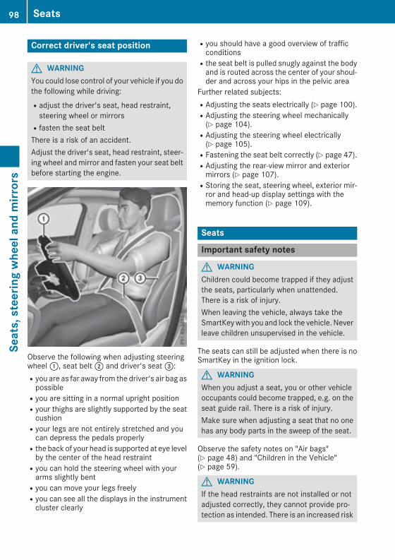
Correct driver's seat position
G WARNINGYou could lose control of your vehicle if you dothe following while driving:Radjust the driver's seat, head restraint,steering wheel or mirrorsRfasten the seat beltThere is a risk of an accident.Adjust the driver's seat, head restraint, steer-ing wheel andmirror and fasten your seat beltbefore starting the engine.
Observe the following when adjusting steeringwheel:, seat belt; and driver's seat=:Ryou are as far away from the driver's air bag aspossibleRyou are sitting in a normal upright positionRyour thighs are slightly supported by the seatcushionRyour legs are not entirely stretched and youcan depress the pedals properlyRthe back of your head is supported at eye levelby the center of the head restraintRyou can hold the steering wheel with yourarms slightly bentRyou can move your legs freelyRyou can see all the displays in the instrumentcluster clearly
Ryou should have a good overview of trafficconditionsRthe seat belt is pulled snugly against the bodyand is routed across the center of your shoul-der and across your hips in the pelvic area
Further related subjects:RAdjusting the seats electrically (Y page 100).RAdjusting the steering wheel mechanically(Y page 104).RAdjusting the steering wheel electrically(Y page 105).RFastening the seat belt correctly (Y page 47).RAdjusting the rear-view mirror and exteriormirrors (Y page 107).RStoring the seat, steering wheel, exterior mir-ror and head-up display settings with thememory function (Y page 109).
Seats
Important safety notes
G WARNINGChildren could become trapped if they adjustthe seats, particularly when unattended.There is a risk of injury.When leaving the vehicle, always take theSmartKeywith you and lock the vehicle. Neverleave children unsupervised in the vehicle.
The seats can still be adjusted when there is noSmartKey in the ignition lock.
G WARNINGWhen you adjust a seat, you or other vehicleoccupants could become trapped, e.g. on theseat guide rail. There is a risk of injury.Make sure when adjusting a seat that no onehas any body parts in the sweep of the seat.
Observe the safety notes on "Air bags"(Y page 48) and "Children in the Vehicle"(Y page 59).
G WARNINGIf the head restraints are not installed or notadjusted correctly, they cannot provide pro-tection as intended. There is an increased risk
98 SeatsSeats,steerin
gwheelandmirrors
of injury in the head and neck area, e.g. in theevent of an accident or when braking.Always drive with the head restraints instal-led. Before driving off, make sure for everyvehicle occupant that the center of the headrestraint supports the back of the head atabout eye level.
Do not rotate the head restraints of the front andrear seats. Otherwise, you cannot adjust theheight and angle of the head restraints cor-rectly.Using the fore-and-aft adjustment, adjust thehead restraint so that it is as close as possible toyour head.
G WARNINGIf the driver's seat is not engaged, it couldmove unexpectedly while the vehicle is inmotion. This could cause you to lose control ofthe vehicle. There is a risk of an accident.Always make sure that the driver's seat isengaged before starting the vehicle.
G WARNINGYou could lose control of your vehicle if you dothe following while driving:Radjust the driver's seat, head restraint,steering wheel or mirrorsRfasten the seat beltThere is a risk of an accident.Adjust the driver's seat, head restraint, steer-ing wheel andmirror and fasten your seat beltbefore starting the engine.
G WARNINGIf you adjust the seat height carelessly, you orother vehicle occupants could be trapped andthereby injured. Children in particular couldaccidentally press the electrical seat adjust-ment buttons and become trapped. There is arisk of injury.While moving the seats, make sure that yourhands or other body parts do not get under thelever assembly of the seat adjustment sys-tem.
G WARNINGThe seat belt does not offer the intended levelof protection if you have not moved the back-rest to an almost vertical position. When brak-ing or in the event of an accident, you couldslide underneath the seat belt and sustainabdomen or neck injuries, for example. Thisposes an increased risk of injury or even fatalinjury.Adjust the seat properly before beginningyour journey. Always ensure that the backrestis in an almost vertical position and that theshoulder section of your seat belt is routedacross the center of your shoulder.
! To avoid damage to the seats and the seatheating, observe the following information:Rkeep liquids from spilling on the seats. Ifliquid is spilled on the seats, dry them assoon as possible.Rif the seat covers are damp or wet, do notswitch on the seat heating. The seat heat-ing should also not be used to dry the seats.Rclean the seat covers as recommended;see "Interior care".Rdo not transport heavy loads on the seats.Do not place sharp objects on the seatcushions, e.g. knives, nails or tools. Theseats should only be occupied by passen-gers, if possible.Rwhen the seat heating is in operation, donot cover the seats with insulating materi-als, e.g. blankets, coats, bags, seat covers,child seats or booster seats.
! Make sure that there are no objects in thefootwell under or behind the seats whenmov-ing the seats back. There is a risk that theseats and/or the objects could be damaged.
i The rear-compartment head restraints canbe removed (Y page 102).For more information, contact a qualified spe-cialist workshop.
i Related topic:REASY-PACK Quickfold rear bench seat(Y page 281)
Seats 99
Seats,steerin
gwheelandmirrors
Z
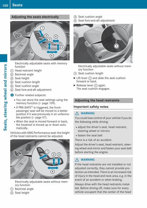
Adjusting the seats electrically
Electrically adjustable seats with memoryfunction
: Head restraint height; Backrest angle= Seat height? Seat cushion lengthA Seat cushion angleB Seat fore-and-aft adjustment
i Further related subjects:RYou can store the seat settings using thememory function (Y page 109).RIf PRE-SAFE® is triggered, the front-passenger seat will be moved to a betterposition if it was previously in an unfavora-ble position (Y page 57).RWhen the seat is moved forward or back,the headrest is moved up or down auto-matically.
Vehicleswith AMGPerformance seat: the heightof the head restraints cannot be adjusted.
Electrically adjustable seats without mem-ory function
: Backrest angle; Seat height
= Seat cushion angle? Seat fore-and-aft adjustment
Electrically adjustable seats without mem-ory function
: Seat cushion lengthX Lift lever: and slide the seat cushionforward or back.
X Release lever: again.The seat cushion engages.
Adjusting the head restraints
Important safety notes
G WARNINGYou could lose control of your vehicle if you dothe following while driving:Radjust the driver's seat, head restraint,steering wheel or mirrorsRfasten the seat beltThere is a risk of an accident.Adjust the driver's seat, head restraint, steer-ing wheel andmirror and fasten your seat beltbefore starting the engine.
G WARNINGIf the head restraints are not installed or notadjusted correctly, they cannot provide pro-tection as intended. There is an increased riskof injury in the head and neck area, e.g. in theevent of an accident or when braking.Always drive with the head restraints instal-led. Before driving off, make sure for everyvehicle occupant that the center of the head
100 SeatsSeats,steerin
gwheelandmirrors

restraint supports the back of the head atabout eye level.
General notesPay attention to the important safety notes(Y page 98).Do not rotate the head restraints of the front andrear seats. Otherwise, you cannot adjust theheight and angle of the head restraints to thecorrect position.
Adjusting the head restraint heightmanually
X To raise: pull the head restraint up to thedesired position.
X To lower: press release catch: in the direc-tion of the arrow and push the head restraintdown to the desired position.
Adjusting the head restraint fore-and-aft position manually
With this function you can adjust the distancebetween the head restraint and the back of theseat occupant's head.
X To move forward: pull the head restraintforward in the direction of the arrow until itengages in the desired position.
X To move back: press and hold the releasecatch:.
X Push the head restraint back.X Release the release button once the headrestraint is in the desired position.
X Ensure that the head restraint has engagedproperly.
Using the fore-and-aft adjustment, adjust thehead restraint so that it is as close as possible toyour head.
Adjusting the height of the headrestraints electricallyX To adjust the head restraint height: slidethe switch for the head restraint adjustment(Y page100) up or down in the direction of thearrow.
Adjusting the rear seat head restraintheight
X Once the head restraint is fully lowered, pressrelease catch:.
X To raise: pull the head restraint up to thedesired height.
X To lower: press release catch: and pushthe head restraint down until it is in thedesired position.
Seats 101
Seats,steerin
gwheelandmirrors
Z

Installing and removing rear headrestraintsX Release the rear seat backrest and fold itslightly forward (Y page 281).
X To remove: pull the head restraint up to thestop.
X Press release catch: and pull the headrestraint out of the guides.
X To re-install: insert the head restraint so thatthe notches on the bar are on the left whenviewed in the direction of travel.
X Push the head restraint down until you hear itengage in position.
X Fold back the rear seat backrest until itengages.
Adjusting the 4-way lumbar support
: Raises the backrest contour; Softens the backrest contour= Lowers the backrest contour? Hardens the backrest contourYou can adjust the contour of the front seatbackrests individually to provide optimum sup-port for your back.
Adjusting the AMG Performance SeatTo adjust the contour of the seat and forimproved lateral support, you can individuallyadjust the front seats.
Adjusting the side bolsters of the seat cush-ionX To set narrower: press button:.X To set wider: press button;.To adjust the side bolsters of the seat back-restX To set narrower: press button=.X To set wider: press button?.Adjusting the seat cushion length mechani-callyX Lift handleA and slide the seat cushionforward or back.
X Release leverA again.The seat cushion engages.
Switching the seat heating on/off
Switching on/off
G WARNINGRepeatedly switching on the seat heating cancause the seat cushion and backrest pads tobecome very hot. The health of persons withlimited temperature sensitivity or a limitedability to react to excessively high tempera-tures may be affected or they may even sufferburn-like injuries. There is a risk of injury.Therefore, do not switch the seat heating onrepeatedly.
102 SeatsSeats,steerin
gwheelandmirrors

Front seats
Rear seatsThe three red indicator lamps in the button indi-cate the heating level you have selected.The system automatically switches down fromlevel 3 to level 2 after approximately eightminutes.The system automatically switches down fromlevel 2 to level 1 after approximately tenminutes.The system automatically switches off approx-imately 20 minutes after it is set to level 1.X Turn the SmartKey to position1 or2 in theignition lock (Y page 132).
X To switch on: press button: repeatedlyuntil the desired heating level is set.
X To switch off: press button: repeatedlyuntil all the indicator lamps go out.
i If the battery voltage is too low, the seatheating may switch off.
i If drive program E is selected, the power ofthe seat heating is reduced.
Switching the seat ventilation on/off
Switching on/off
The blue indicator lamps in the button indicatethe ventilation level you have selected.X Turn the SmartKey to position1 or2 in theignition lock (Y page 132).
X To switch on:press button: repeatedlyuntil the desired ventilation level is set.
X To switch off: press button: repeatedlyuntil all the indicator lamps go out.
i If the battery voltage is too low, the seatventilation may switch off.
i You can open the side windows and the slid-ing sunroof using the "Convenience opening"feature (Y page 91). The seat ventilation ofthe driver's seat automatically switches to thehighest level.
i When the vehicle is stationary, the fanspeed can be reduced automatically. Thisreduces the noises of the seat ventilation.
Seats 103
Seats,steerin
gwheelandmirrors
Z

Problems with the seat heating / seat ventilation
Problem Possible causes/consequences andM Solutions
The seat heating or seatventilation has switchedoff prematurely or can-not be switched on.
The on-board voltage is too low because too many electrical consum-ers are switched on.X Switch off electrical consumers that you do not need, such as therear window defroster or interior lighting.Once the battery is sufficiently charged, the seat heating or seatventilation can be switched back on manually.
Steering wheel
Important safety notes
G WARNINGYou could lose control of your vehicle if you dothe following while driving:Radjust the driver's seat, head restraint,steering wheel or mirrorsRfasten the seat beltThere is a risk of an accident.Adjust the driver's seat, head restraint, steer-ing wheel andmirror and fasten your seat beltbefore starting the engine.
G WARNINGChildren could injure themselves if theyadjust the steering wheel. There is a risk ofinjury.When leaving the vehicle, always take theSmartKeywith you and lock the vehicle. Neverleave children unsupervised in the vehicle.
The electrically adjustable steering wheel canstill be adjusted when there is no key in the igni-tion lock.
Adjusting the steering wheel man-ually
: Release lever; Adjusts the steering wheel height= Adjusts the steering wheel position (fore-
and-aft adjustment)X Push release lever: down completely.The steering column is unlocked.
X Adjust the steering wheel to the desired posi-tion.
X Push release lever: up as far as it will go.The steering column is locked.
X Check if the steering column is locked. Whendoing so, try to push the steering wheel up ordown or try to move it in the fore-and-aftdirection.
104 Steering wheelSeats,steerin
gwheelandmirrors

Adjusting the steering wheel electri-cally
: Adjusts the steering wheel height; Adjusts the steering wheel position (fore-
and-aft adjustment)
i Further related subjects:REASY-ENTRY/EXIT feature (Y page 105)RStoring settings (Y page 109)
Steering wheel heating
Switching on/off
X Turn the SmartKey to position2 in the igni-tion lock (Y page 132).
X To switch on/off: turn the lever in the direc-tion of arrow: or;.Indicator lamp= lights up or goes out.
If you switch off the ignition, the steering wheelheating is deactivated.
Problems with the steering wheel heating
Problem Possible causes/consequences andM Solutions
The steering wheel heat-ing has switched off pre-maturely or cannot beswitched on.
The on-board voltage is too low because too many electrical consum-ers are switched on.X Switch off electrical consumers that you do not need, such as therear window defroster or interior lighting.
EASY-ENTRY/EXIT feature
Important safety notes
G WARNINGWhen the EASY-ENTRY/EXIT feature adjuststhe steering wheel, you and other vehicleoccupants – particularly children – couldbecome trapped. There is a risk of injury.While the EASY-ENTRY/EXIT feature is mak-ing adjustments, make sure that no one hasany body parts in the sweep of the steeringwheel.Move the steering wheel adjustment lever ifthere is a risk of entrapment by the steeringwheel. The adjustment process is stopped.
You can stop the adjustment process by press-ing one of the memory function's position but-tons. This function is only available on vehicleswith memory function.
G WARNINGIf children activate the EASY-ENTRY/EXIT fea-ture, they can become trapped, particularlywhen unattended. There is a risk of injury.When leaving the vehicle, always take theSmartKeywith you and lock the vehicle. Neverleave children unsupervised in the vehicle.
G WARNINGIf you drive off while the EASY-ENTRY/EXITfeature is making adjustments, you could lose
Steering wheel 105
Seats,steerin
gwheelandmirrors
Z
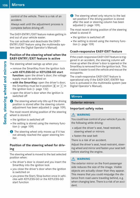
control of the vehicle. There is a risk of anaccident.Always wait until the adjustment process iscomplete before driving off.
The EASY-ENTRY/EXIT feature makes getting inand out of your vehicle easier.You can activate and deactivate the EASY-ENTRY/EXIT feature using the multimedia sys-tem (see the Digital Operator's Manual)
Position of the steering wheel when theEASY-ENTRY/EXIT feature is activeThe steering wheel swings up when you:Rremove the SmartKey from the ignition lockRwith KEYLESS-GO or KEYLESS-GO startfunction: open the driver's door; the voltagesupply must be switched onRwith the SmartKey: open the driver's door;the SmartKey must be in positiong or1 inthe ignition lock (Y page 132)Ropen the driver's door when the ignition isswitched off
i The steering wheel only tilts up if the drivingposition is stored after the steering columnadjustment has been adjusted (Y page 109).
The most recent driving position of the steeringwheel is stored if:Rthe ignition is switched offRthe setting is stored using the memory func-tion (Y page 109)
i The steering wheel only moves up if it hasnot already reached the upper steering lim-iter.
Position of the steering wheel for driv-ingThe steering wheel is moved to the last selectedposition when:Rthe driver's door is closed and you insert theSmartKey into the ignition lockRyou close the driver's door when the ignitionis switched onRyou press the Start/Stop button once in vehi-cles with KEYLESS-GO or the KEYLESS-GOstart function
i The steering wheel only returns to the lastset position if the driving position is storedafter the seat or steering column has beenadjusted (Y page 109).
The most recent driving position of the steeringwheel is stored if:Rthe ignition is switched offRthe setting is stored using the memory func-tion (Y page 109)
Crash-responsive EASY-EXIT featureIf the crash-responsive EASY-EXIT feature is trig-gered in an accident, the steering column willmove up when the driver's door is opened or theSmartKey is removed from the ignition lock. Thismakes it easier to exit the vehicle and rescue theoccupants.The crash-responsive EASY-EXIT feature isoperational only if the EASY-EXIT/ENTRY fea-ture is activated in the multimedia system (seeDigital Operator's Manual).
Mirrors
Exterior mirrors
Important safety notes
G WARNINGYou could lose control of your vehicle if you dothe following while driving:Radjust the driver's seat, head restraint,steering wheel or mirrorsRfasten the seat beltThere is a risk of an accident.Adjust the driver's seat, head restraint, steer-ing wheel and mirror and fasten your seat beltbefore starting the engine.
G WARNINGThe exterior mirror on the front-passengerside reduces the size of the image. Visibleobjects are actually closer than they appear.This means that you could misjudge the dis-tance from road users traveling behind, e.g.when changing lane. There is a risk of an acci-dent.
106 MirrorsSeats,steerin
gwheelandmirrors
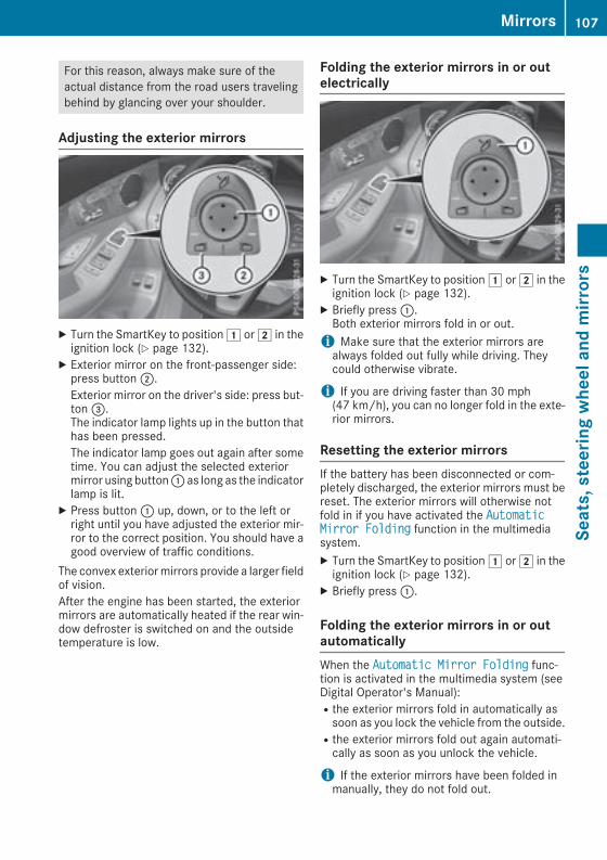
For this reason, always make sure of theactual distance from the road users travelingbehind by glancing over your shoulder.
Adjusting the exterior mirrors
X Turn the SmartKey to position1 or2 in theignition lock (Y page 132).
X Exterior mirror on the front-passenger side:press button;.Exterior mirror on the driver's side: press but-ton=.The indicator lamp lights up in the button thathas been pressed.The indicator lamp goes out again after sometime. You can adjust the selected exteriormirror using button: as long as the indicatorlamp is lit.
X Press button: up, down, or to the left orright until you have adjusted the exterior mir-ror to the correct position. You should have agood overview of traffic conditions.
The convex exteriormirrors provide a larger fieldof vision.After the engine has been started, the exteriormirrors are automatically heated if the rear win-dow defroster is switched on and the outsidetemperature is low.
Folding the exterior mirrors in or outelectrically
X Turn the SmartKey to position1 or2 in theignition lock (Y page 132).
X Briefly press:.Both exterior mirrors fold in or out.i Make sure that the exterior mirrors arealways folded out fully while driving. Theycould otherwise vibrate.
i If you are driving faster than 30 mph(47 km/h), you can no longer fold in the exte-rior mirrors.
Resetting the exterior mirrorsIf the battery has been disconnected or com-pletely discharged, the exterior mirrors must bereset. The exterior mirrors will otherwise notfold in if you have activated the AutomaticMirror Folding function in the multimediasystem.X Turn the SmartKey to position1 or2 in theignition lock (Y page 132).
X Briefly press:.
Folding the exterior mirrors in or outautomaticallyWhen the Automatic Mirror Folding func-tion is activated in the multimedia system (seeDigital Operator's Manual):Rthe exterior mirrors fold in automatically assoon as you lock the vehicle from the outside.Rthe exterior mirrors fold out again automati-cally as soon as you unlock the vehicle.
i If the exterior mirrors have been folded inmanually, they do not fold out.
Mirrors 107
Seats,steerin
gwheelandmirrors
Z

Exterior mirror pushed out of positionIf an exterior mirror has been pushed out ofposition, proceed as follows:X Vehicles without electrically folding exte-rior mirrors:manually move the exterior mir-ror into the correct position.
X Vehicles with electrically folding exteriormirrors: press and hold button: until youhear a click and then the mirror engaging inposition (Y page 107).The mirror housing is engaged again and youcan adjust the exterior mirrors as usual(Y page 107).
If an exterior mirror has been pushed out ofposition, proceed as follows:X Press and hold button: until you hear a clickand the mirror engages audibly into position(Y page 107).The mirror housing is engaged again and youcan adjust the exterior mirrors as usual(Y page 107).
Automatic anti-glare mirrors
G WARNINGElectrolyte may escape if the glass in an auto-matic anti-glaremirror breaks. The electrolyteis harmful and causes irritation. It must notcome into contact with your skin, eyes, res-piratory organs or clothing or be swallowed.There is a risk of injury.If you come into contact with the electrolyte,observe the following:RRinse off the electrolyte from your skinimmediately with water.RImmediately rinse the electrolyte out ofyour eyes thoroughly with clean water.RIf the electrolyte is swallowed, immediatelyrinse your mouth out thoroughly. Do notinduce vomiting.RIf electrolyte comes into contact with yourskin or hair or is swallowed, seek medicalattention immediately.
RImmediately change out of clothing whichhas come into contact with electrolyte.RIf an allergic reaction occurs, seek medicalattention immediately.
The exterior mirror on the driver's side and therear-view mirror automatically go into anti-glaremode if:Rthe ignition is switched onRincident light from headlamps strikes the sen-sor in the rear-view mirror
The mirrors do not go into anti-glare mode ifreverse gear is engaged or if the interior lightingis switched on.
Parking position for the exterior mir-ror on the front-passenger side
Storing the parking positionYou can set the front-passenger side exteriormirror such that you can see the rear wheel onthat side as soon as you engage reverse gear.You can store this position.
Storing using reverse gear
: Memory button M; Button for the exterior mirror setting= Button for the front-passenger side exterior
mirror? Button for the driver's side exterior mirrorX Start the engine.X Press button=.
108 MirrorsSeats,steerin
gwheelandmirrors

X Engage reverse gear.The exterior mirror on the front-passengerside moves to the preset parking position.
X Use button; to adjust the exterior mirror toa position that allows you to see the rearwheel and the curb.The parking position is stored.i If you shift the transmission to another posi-tion, the exterior mirror on the front-passenger side returns to the driving position.
Saving using the memory buttonYou can store the parking position of the exte-rior mirror on the front-passenger side usingmemory buttonM:. The reverse gearmust notbe engaged.X Turn the SmartKey to position2 in the igni-tion lock (Y page 132).
X Press button=.X Use button; to adjust the exterior mirror toa position that allows you to see the rearwheel and the curb.
X Press memory button M: and one of thearrows on button; within three seconds.The parking position is stored if the exteriormirror does not move.
X If the mirror moves out of position, repeat thesteps.
X After successfully storing, reset the drivingposition of the exterior mirror.
Calling up a stored parking position set-tingX Turn the SmartKey to position2 in the igni-tion lock (Y page 132).
X Adjust the exterior mirror on the front-passenger side using button=.
X Engage reverse gear.The exterior mirror on the front-passengerside moves to the stored parking position.
The exterior mirror on the front-passenger sidemoves back to its original position:Ras soon as you exceed a speed of 9 mph(15 km/h)Rabout ten seconds after you have disengagedreverse gearRwhen you use button? to select the exteriormirror on the driver's side
Memory function
Important safety notes
G WARNINGIf you use thememory function on the driver'sside while driving, you could lose control ofthe vehicle as a result of the adjustmentsbeing made. There is a risk of an accident.Only use the memory function on the driver'sside when the vehicle is stationary.
G WARNINGWhen thememory function adjusts the seat orsteering wheel, you and other vehicle occu-pants – particularly children – could becometrapped. There is a risk of injury.While the memory function is making adjust-ments, make sure that no one has any bodyparts in the sweep of the seat or steeringwheel. If somebody becomes trapped, imme-diately release the memory function positionbutton. The adjustment process is stopped.
G WARNINGChildren could become trapped if they acti-vate the memory function, particularly whenunattended. There is a risk of injury.When leaving the vehicle, always take theSmartKeywith you and lock the vehicle. Neverleave children unsupervised in the vehicle.
The memory function can be used at any time,e.g. even when the SmartKey is not in the igni-tion lock.
Storing settingsWith the memory function, you can store up tothree different settings, e.g. for three differentpeople.The following settings are stored as a singlememory preset:Rposition of the seat, backrest and headrestraintRdriver's side: position of the exterior mirrorson the driver's and front-passenger sidesRposition of the head-up display
Memory function 109
Seats,steerin
gwheelandmirrors
Z
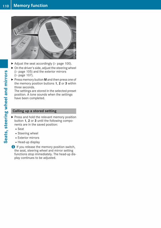
X Adjust the seat accordingly (Y page 100).X On the driver's side, adjust the steering wheel(Y page 105) and the exterior mirrors(Y page 107).
X Pressmemory buttonM and then press one ofthe memory position buttons 1, 2 or 3 withinthree seconds.The settings are stored in the selected presetposition. A tone sounds when the settingshave been completed.
Calling up a stored settingX Press and hold the relevant memory positionbutton 1, 2 or 3 until the following compo-nents are in the saved position:RSeatRSteering wheelRExterior mirrorsRHead-up displayi If you release the memory position switch,the seat, steering wheel and mirror settingfunctions stop immediately. The head-up dis-play continues to be adjusted.
110 Memory functionSeats,steerin
gwheelandmirrors

Exterior lighting
General notesUSA only: if you wish to drive during the daytimewithout lights, switch off the Daytime Run‐ning Lights function via the on-board com-puter (Y page 223).
Setting the exterior lighting
Setting optionsExterior lighting can be set using the:Rlight switch (Y page 111)Rcombination switch (Y page 112)Ron-board computer (Y page 223)
Light switch
Operation
1 W Left-hand standing lamps2 X Right-hand standing lamps3 T Parking lamps, license plate and
instrument cluster lighting4Ã Automatic headlampmode, controlled
by the light sensor5 L Low-beam/high-beam headlampsB R Rear fog lampIf you hear a warning tone when you leave thevehicle, the lights may still be switched on.X Turn the light switch to theà position.The exterior lighting (except the parking/stand-ing lamps) switches off automatically if you:Rremove the SmartKey from the ignition lockRopen the driver's door with the SmartKey inpositionu
Automatic headlamp modeG WARNINGWhen the light switch is set toÃ, the low-beam headlamps may not be switched onautomatically if there is fog, snow or othercauses of poor visibility due to the weatherconditions such as spray. There is a risk of anaccident.In such situations, turn the light switch toL.
The automatic headlamp feature is only an aid.The driver is responsible for the vehicle's light-ing at all times.Ã is the favored light switch setting.The light setting is automatically selectedaccording to the brightness of the ambient light,but not in the event of poor visibility due toweather conditions such as fog, snow or spray.RWith the SmartKey in position1 in the igni-tion lock, the parking lamps are switched onor off automatically depending on the bright-ness of the ambient light.RUSA only: if you have switched on the Day‐time Running Lights function via the on-board computer, and the engine is running,the daytime running lamps or the parkinglamps and low-beam headlamps are switchedon or off automatically depending on theambient light.RCanada only: depending on the ambient light,the daytime running lamps or the parking andlow-beam headlamps are switched on/offautomatically when the engine is running.
X To switch on the automatic headlamps:turn the light switch to theà position.
USA only: The daytime running lamps improvethe visibility of your vehicle during the day. Here,the Daytime Running Lights function mustbe switched on via the on-board computer(Y page 223).If the engine is running and you turn the lightswitch to the T or L position, the manualsettings take precedence over the daytime run-ning lamps.Canada only: The daytime running lampsimprove the visibility of your vehicle during theday. The daytime running lamps function isrequired by law in Canada. It cannot thereforebe deactivated.
Exterior lighting 111
Lightsandwindshieldwipers
Z
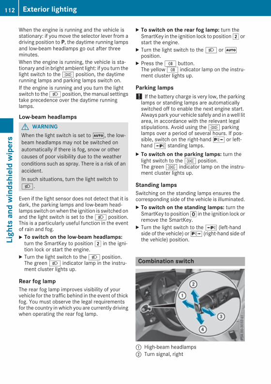
When the engine is running and the vehicle isstationary: if you move the selector lever from adriving position to P, the daytime running lampsand low-beam headlamps go out after threeminutes.When the engine is running, the vehicle is sta-tionary and in bright ambient light: if you turn thelight switch to the T position, the daytimerunning lamps and parking lamps switch on.If the engine is running and you turn the lightswitch to theL position, themanual settingstake precedence over the daytime runninglamps.
Low-beam headlampsG WARNINGWhen the light switch is set toÃ, the low-beam headlamps may not be switched onautomatically if there is fog, snow or othercauses of poor visibility due to the weatherconditions such as spray. There is a risk of anaccident.In such situations, turn the light switch toL.
Even if the light sensor does not detect that it isdark, the parking lamps and low-beam head-lamps switch onwhen the ignition is switched onand the light switch is set to the L position.This is a particularly useful function in the eventof rain and fog.X To switch on the low-beam headlamps:turn the SmartKey to position2 in the igni-tion lock or start the engine.
X Turn the light switch to the L position.The green L indicator lamp in the instru-ment cluster lights up.
Rear fog lampThe rear fog lamp improves visibility of yourvehicle for the traffic behind in the event of thickfog. You must observe the legal requirementsfor the country in which you are currently drivingwhen operating the rear fog lamp.
X To switch on the rear fog lamp: turn theSmartKey in the ignition lock to position2 orstart the engine.
X Turn the light switch to the L orÃposition.
X Press the R button.The yellow R indicator lamp on the instru-ment cluster lights up.
Parking lamps! If the battery charge is very low, the parkinglamps or standing lamps are automaticallyswitched off to enable the next engine start.Always park your vehicle safely and in awell litarea, in accordance with the relevant legalstipulations. Avoid using the T parkinglamps over a period of several hours. If pos-sible, switch on the right-hand X or left-hand W standing lamps.
X To switch on the parking lamps: turn thelight switch to the T position.The green T indicator lamp on the instru-ment cluster lights up.
Standing lampsSwitching on the standing lamps ensures thecorresponding side of the vehicle is illuminated.X To switch on the standing lamps: turn theSmartKey to positionu in the ignition lock orremove the SmartKey.
X Turn the light switch to the W (left-handside of the vehicle) orX (right-hand side ofthe vehicle) position.
Combination switch
: High-beam headlamps; Turn signal, right
112 Exterior lightingLightsandwindshieldwipers

= High-beam flasher? Turn signal, leftX To indicate briefly: press the combinationswitch briefly to the pressure point in thedirection of arrow; or?.The corresponding turn signal flashes threetimes.
X To indicate: press the combination switchbeyond the pressure point in the direction ofarrow; or?.
X To switch on the high-beam headlamps:turn the light switch to the L orÃposition.
X Press the combination switch beyond thepressure point in the direction of arrow:.In theà position, the high-beam head-lamps are switched on onlywhen it is dark andthe engine is running.The blue K indicator lamp on the instru-ment cluster lights up when the high-beamheadlamps are switched on.
X To switch off the high-beam headlamps:move the combination switch back to its nor-mal position.The blue K indicator lamp on the instru-ment cluster goes out.
Vehicles with Adaptive Highbeam Assist:If Adaptive Highbeam Assist is active, it auto-matically controls activation and deactivation ofthe high-beam headlamps (Y page 113).X High-beam flasher: pull the combinationswitch in the direction of arrow=.
Hazard warning lamps
X To switch the hazard warning lamps on oroff: press button:.The turn signal lamps flash when the hazardwarning lamps are switched on. If you now
switch on a turn signal lamp using the com-bination switch, only the turn signal lamp onthe corresponding side of the vehicle willflash.
The hazard warning lamps switch on automati-cally if an air bag is deployed.The hazard warning lamps still operate if theignition is switched off.
Cornering light functionThe cornering light function improves the illu-mination of the road over a wide angle in thedirection you are turning, enabling better visi-bility in tight bends, for example. It can only beactivated when the low-beam headlamps areswitched on.Active:Rif you are driving at speeds below 25 mph(40 km/h) and switch on the turn signal orturn the steering wheelRif you are driving at speeds between 25 mph(40 km/h) and 45 mph (70 km/h) and turnthe steering wheel
The cornering lamp may remain lit for a shorttime, but is automatically switched off after nomore than three minutes.Cornering light function with traffic circlefunction:The cornering light function is activated on bothsides before entering a traffic circle through anevaluation of the current GPS position of thevehicle. It remains active until after the vehiclehas left the traffic circle. In this way, pedestrianscrossing the road, for example, are illuminatedby your vehicle in good time.Only vehicleswith theCOMANDmultimedia sys-tem have this function.
Adaptive Highbeam Assist
General notesYou can use this function to set the headlampsto change between low beam and high beamautomatically. The system recognizes vehicleswith their lights on, either approaching from theopposite direction or traveling in front of yourvehicle, and consequently switches the head-lamps from high beam to low beam.
Exterior lighting 113
Lightsandwindshieldwipers
Z
The system automatically adapts the low-beamheadlamp range depending on the distance tothe other vehicle. Once the system no longerdetects any other vehicles, it reactivates thehigh-beam headlamps.The system's optical sensor is located behindthe windshield near the overhead control panel.
Important safety notes
G WARNINGAdaptive HighbeamAssist does not recognizeroad users:Rwho have no lights, e.g. pedestriansRwho have poor lighting, e.g. cyclistsRwhose lighting is blocked, e.g. by a barrierOn very rare occasions, Adaptive HighbeamAssist may fail to recognize other road usersthat have lights, or may recognize them toolate. In this, or in similar situations, the auto-matic high-beam headlamps will not be deac-tivated orwill be activated regardless. There isa risk of an accident.Always carefully observe the traffic conditionsand switch off the high-beam headlamps ingood time.
Adaptive Highbeam Assist cannot take intoaccount road, weather or traffic conditions.Adaptive HighbeamAssist is only an aid. You areresponsible for adjusting the vehicle's lightingto the prevailing light, visibility and traffic con-ditions.In particular, the detection of obstacles can beimpaired if:Rthere is poor visibility, e.g. due to fog, heavyrain or snowRthere is dirt on the sensors or anything elsecovering the sensors
Switching Adaptive Highbeam Assiston/offX To switch on: turn the light switch to theà position.
X Press the combination switch forwardsbeyond the pressure point (Y page 112).The _ indicator lamp on the multifunctiondisplay lights up when it is dark and the lightsensor switches on the low-beam headlamps.
If you are driving at speeds above approx-imately 16 mph (25 km/h):The headlamp range is set automaticallydepending on the distance between the vehi-cle and other road users.If you are driving at speeds above approx-imately 19 mph (30 km/h) and no other roadusers are detected:The high-beam headlamps are switched onautomatically. TheK indicator lamp on theinstrument cluster also lights up.If you are driving at speeds below approx-imately 16mph (25 km/h) or other road usersare detected or the roads are adequately lit:The high-beam headlamps are switched offautomatically. TheK indicator lamp on theinstrument cluster goes out. The _ indi-cator lamp on the multifunction displayremains lit.
X To switch off: move the combination switchback to its normal position or move the lightswitch to another position.The K indicator lamp on the instrumentcluster goes out.
Headlamps fogged up on the insideCertain climatic and physical conditions maycause moisture to form in the headlamp. Thismoisture does not affect the functionality of theheadlamp.
114 Exterior lightingLightsandwindshieldwipers
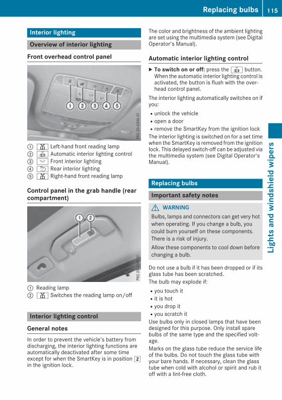
Interior lighting
Overview of interior lighting
Front overhead control panel
: p Left-hand front reading lamp; | Automatic interior lighting control= c Front interior lighting? u Rear interior lightingA p Right-hand front reading lamp
Control panel in the grab handle (rearcompartment)
: Reading lamp; p Switches the reading lamp on/off
Interior lighting control
General notesIn order to prevent the vehicle's battery fromdischarging, the interior lighting functions areautomatically deactivated after some timeexcept for when the SmartKey is in position2in the ignition lock.
The color and brightness of the ambient lightingare set using the multimedia system (see DigitalOperator's Manual).
Automatic interior lighting controlX To switch on or off: press the | button.When the automatic interior lighting control isactivated, the button is flush with the over-head control panel.
The interior lighting automatically switches on ifyou:Runlock the vehicleRopen a doorRremove the SmartKey from the ignition lockThe interior lighting is switched on for a set timewhen the SmartKey is removed from the ignitionlock. This delayed switch-off can be adjusted viathe multimedia system (see Digital Operator'sManual).
Replacing bulbs
Important safety notes
G WARNINGBulbs, lamps and connectors can get very hotwhen operating. If you change a bulb, youcould burn yourself on these components.There is a risk of injury.Allow these components to cool down beforechanging a bulb.
Do not use a bulb if it has been dropped or if itsglass tube has been scratched.The bulb may explode if:Ryou touch itRit is hotRyou drop itRyou scratch itUse bulbs only in closed lamps that have beendesigned for this purpose. Only install sparebulbs of the same type and the specified volt-age.Marks on the glass tube reduce the service lifeof the bulbs. Do not touch the glass tube withyour bare hands. If necessary, clean the glasstube when cold with alcohol or spirit and rub itoff with a lint-free cloth.
Replacing bulbs 115
Lightsandwindshieldwipers
Z
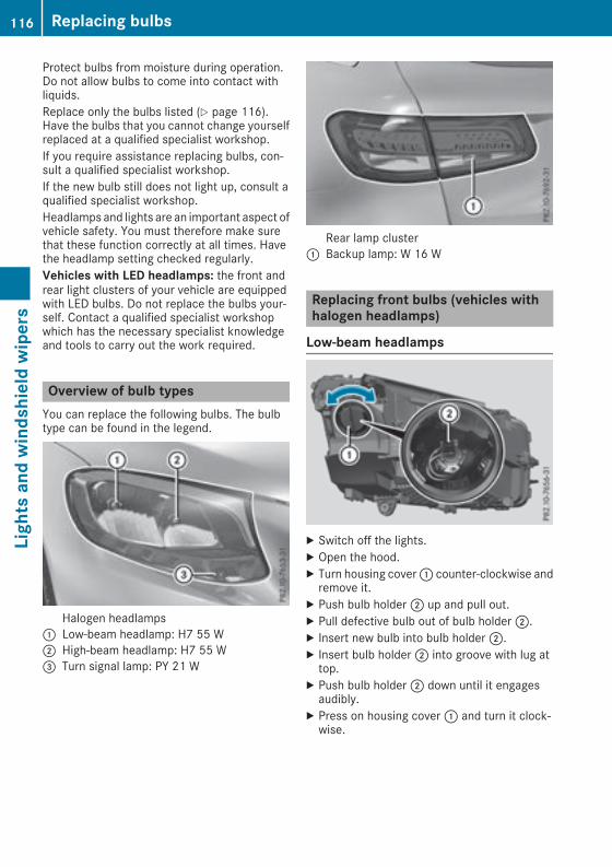
Protect bulbs from moisture during operation.Do not allow bulbs to come into contact withliquids.Replace only the bulbs listed (Y page 116).Have the bulbs that you cannot change yourselfreplaced at a qualified specialist workshop.If you require assistance replacing bulbs, con-sult a qualified specialist workshop.If the new bulb still does not light up, consult aqualified specialist workshop.Headlamps and lights are an important aspect ofvehicle safety. You must therefore make surethat these function correctly at all times. Havethe headlamp setting checked regularly.Vehicles with LED headlamps: the front andrear light clusters of your vehicle are equippedwith LED bulbs. Do not replace the bulbs your-self. Contact a qualified specialist workshopwhich has the necessary specialist knowledgeand tools to carry out the work required.
Overview of bulb typesYou can replace the following bulbs. The bulbtype can be found in the legend.
Halogen headlamps: Low-beam headlamp: H7 55 W; High-beam headlamp: H7 55 W= Turn signal lamp: PY 21 W
Rear lamp cluster: Backup lamp: W 16 W
Replacing front bulbs (vehicles withhalogen headlamps)
Low-beam headlamps
X Switch off the lights.X Open the hood.X Turn housing cover: counter-clockwise andremove it.
X Push bulb holder; up and pull out.X Pull defective bulb out of bulb holder;.X Insert new bulb into bulb holder;.X Insert bulb holder; into groove with lug attop.
X Push bulb holder; down until it engagesaudibly.
X Press on housing cover: and turn it clock-wise.
116 Replacing bulbsLightsandwindshieldwipers

High-beam headlamps
X Switch off the lights.X Open the hood.X Turn housing cover: counter-clockwise andremove it.
X Push bulb holder; upwards and pull out.X Pull defective bulb out of bulb holder;.X Insert new bulb into bulb holder;.X Insert bulb holder; into groove with lug attop.
X Push bulb holder; down until it engagesaudibly.
X Press on housing cover: and turn it clock-wise.
Turn signals
X Remove the cover in the front wheel housing(Y page 117).
X Turn bulb holder: counter-clockwise usingthe grip under the headlamp casing andremove it downwards with bulb.
X Turn defective bulb counter-clockwise andremove it from bulb holder:.
X Insert new bulb into bulb holder:.
X Insert bulb holder:, turn it clockwise andlock.
X Replace the cover in the front wheel housing(Y page 117).
Removing and installing the cover in thefront wheel housingYou must remove the cover of the front wheelhousing before you can change the front turnsignal lamp.
X To remove: switch off the lights.X Turn the front wheels inwards.X Turn rotary knob: 180° outwards until itstops using a suitable object.Cover; is released.
X Fold cover; up.X To install: insert cover; into the left, rightand two lower catches.
X Turn rotary knob: 180° inwards until itstops using a suitable object.Cover; is locked.
Replacing bulbs 117
Lightsandwindshieldwipers
Z

Replacing rear bulbs (vehicles withhalogen headlamps)
Opening and closing the side trim pan-els
Example: right-hand side panelingYou must open the side trim panel in the cargocompartment before you can replace the bulbsin the tail lamps.X To open: release right or left side trimpanel: at the top and fold it down in thedirection of the arrow.
X To close: insert side trim panel:.
Rear lamp cluster
Changing the backup lampDue to their location, have the bulbs in thebackup lamp in the tailgate replaced at a quali-fied specialist workshop.X Switch off the lights.X Open the tailgate.
Example: right-hand side handleX In recess? on the inside of the closing han-dle, pry off and remove the upper section of
handle= with a flat, smooth object, e.g. ascrewdriver.
X Pull the lower section of handle: with astrong tug to remove it from the trim and thenplace it to one side.
X Reach under the right-hand side of trimBand lightly tug along the entire length of thetrim in order to unclip it.
X Pull out connectorC of the surround lightingby releasing the latches.
X Vehicleswith EASY-PACK tailgate: pull out theplug connector for the switch at the top rightof the trim.
X Vehicles with electric fold-out trailer towhitch: unlock and pull out the plug connectorfor the switch at the top left of the trim.
X Place trimB to one side.
X Unclip the remaining part of trimD from theassembly on the corresponding side using asudden, sharp movement, until bulb holderE is accessible.
118 Replacing bulbsLightsandwindshieldwipers

X Pull the defective bulb out of bulb holderE.X Insert the new bulb into bulb holderE.X Position trimD and engage it in place bytapping it with your hand.
X Check that all the metal clips are inserted inthe parts that were placed to one side: twoclips; in the upper section of handle= andfour clipsA in trimB.
X If not, remove the missing metal clips fromthe metal openings in the tailgate and insertthem in the appropriate places.
X Grasp trimB and connect plug connectorCto the surround lighting.i The surround lighting only illuminates whenthe tailgate has been shut and reopened.
X Vehicles with EASY-PACK tailgate: insert theplug connector for the switch at the top rightof the trim.
X Vehicles with electric fold-out trailer towhitch: insert the plug connector for the switchat the top left of the trim.
X Position trimB and engage it in place bytapping it with your hand, starting from theoutside.
X Clip in the lower section of handle: again.X Insert and engage the upper section of handle= into lower section:.
Windshield wipers
Switching the windshield wiperson/off! Do not operate the windshield wipers whenthe windshield is dry, as this could damagethe wiper blades. Moreover, dust that has col-lected on thewindshield can scratch the glassif wiping takes place when the windshield isdry.
If it is necessary to switch on the windshieldwipers in dry weather conditions, always usewasher fluid when operating the windshieldwipers.
! If the windshield wipers leave smears on thewindshield after the vehicle has been washedin an automatic car wash, wax or other resi-dues may be the reason for this. Clean thewindshield using washer fluid after washingthe vehicle in an automatic car wash.
! Intermittent wiping with rain sensor: due tooptical influences and the windshield becom-ing dirty in dry weather conditions, the wind-shield wipers may be activated inadvertently.This could then damage the windshield wiperblades or scratch the windshield.For this reason, you should always switch offthe windshield wipers in dry weather.
1 $ Windshield wiper off2 Ä Intermittent wipe, normal3 Å Intermittent wipe, frequent4 ° Continuous wipe, slow5 ¯ Continuous wipe, fastB í Single wipe
î Wipe with washer fluidX Switch on the ignition.X Turn the combination switch to the corre-sponding position.
Vehicles with a rain sensor: in the Å orÄ position, the appropriate wipe frequencyis automatically set according to the intensity ofthe rain. In the Å position, the rain sensor ismore sensitive than in the Ä position, caus-ing the windshield wiper to wipe more fre-quently.If the wiper blades are worn, the windshield willno longer be wiped properly. This could preventyou from observing the traffic conditions.
Windshield wipers 119
Lightsandwindshieldwipers
Z
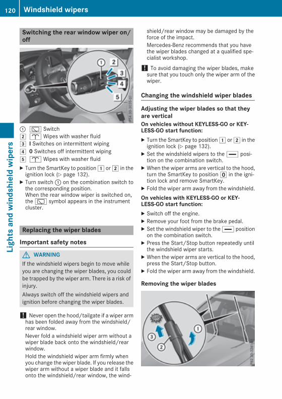
Switching the rear window wiper on/off
: è Switch2 b Wipes with washer fluid3 I Switches on intermittent wiping4 0 Switches off intermittent wiping5 b Wipes with washer fluidX Turn the SmartKey to position1 or2 in theignition lock (Y page 132).
X Turn switch: on the combination switch tothe corresponding position.When the rear window wiper is switched on,the è symbol appears in the instrumentcluster.
Replacing the wiper blades
Important safety notes
G WARNINGIf the windshield wipers begin to move whileyou are changing the wiper blades, you couldbe trapped by the wiper arm. There is a risk ofinjury.Always switch off the windshield wipers andignition before changing the wiper blades.
! Never open the hood/tailgate if a wiper armhas been folded away from the windshield/rear window.Never fold a windshield wiper arm without awiper blade back onto the windshield/rearwindow.Hold the windshield wiper arm firmly whenyou change the wiper blade. If you release thewiper arm without a wiper blade and it fallsonto the windshield/rear window, the wind-
shield/rear window may be damaged by theforce of the impact.Mercedes-Benz recommends that you havethe wiper blades changed at a qualified spe-cialist workshop.
! To avoid damaging the wiper blades, makesure that you touch only the wiper arm of thewiper.
Changing the windshield wiper blades
Adjusting the wiper blades so that theyare verticalOn vehicles without KEYLESS-GO or KEY-LESS‑GO start function:X Turn the SmartKey to position1 or2 in theignition lock (Y page 132).
X Set the windshield wipers to the ° posi-tion on the combination switch.
X When the wiper arms are vertical to the hood,turn the SmartKey to positionu in the igni-tion lock and remove SmartKey.
X Fold the wiper arm away from the windshield.On vehicles with KEYLESS-GO or KEY-LESS‑GO start function:X Switch off the engine.X Remove your foot from the brake pedal.X Set the windshield wiper to the ° positionon the combination switch.
X Press the Start/Stop button repeatedly untilthe windshield wiper starts.
X When the wiper arms are vertical to the hood,press the Start/Stop button.
X Fold the wiper arm away from the windshield.
Removing the wiper blades
120 Windshield wipersLightsandwindshieldwipers

X Hold on to the wiper arm with one hand. Withthe other hand, turn the wiper blade in thedirection of arrow: away from thewiper armas far as it will go.
X Slide the catch; in the direction of arrow=until it engages in the removal position with anoticeable click.
X Remove the wiper blade in the direction ofarrow? away from the wiper arm.
Installing the wiper blades
X Insert the new wiper blade into the wiper armin the direction of arrow:.
X Slide the catch; in the direction of arrow=until it engages in the locking position with anoticeable click.
X Make sure that the wiper blade is seated cor-rectly.
X Fold the wiper arm back onto the windshield.
X Remove the protective film: from the ser-vice indicator on the tip of the wiper blade.
If the color of the service indicator changes fromblack to yellow, the wiper blades should bereplaced.
i The duration of the color change variesdepending on the usage conditions.
Replacing the rear window wiper blade
Removing a wiper blade
X Switch off the engine.X Remove the SmartKey from the ignition lock.or, on vehicles with KEYLESS-GO or KEY-LESS‑GO start function:X Open the driver's door.The vehicle electronics are now in positionu. This is the same as: "Key removed".
Windshield wipers 121
Lightsandwindshieldwipers
Z
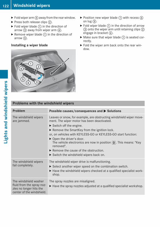
X Foldwiper arm? away from the rearwindow.X Press both release clips;.X Fold wiper blade: in the direction ofarrow= away from wiper arm?.
X Remove wiper blade: in the direction ofarrowA.
Installing a wiper blade
X Position new wiper blade: with recessBon lugA.
X Fold wiper blade: in the direction of arrow= onto the wiper arm until retaining clips;engage in bracket?.
X Make sure that wiper blade: is seated cor-rectly.
X Fold the wiper arm back onto the rear win-dow.
Problems with the windshield wipers
Problem Possible causes/consequences and M Solutions
The windshield wipersare jammed.
Leaves or snow, for example, are obstructing windshield wiper move-ment. The wiper motor has been deactivated.X Switch off the engine.X Remove the SmartKey from the ignition lock.or, on vehicles with KEYLESS-GO or KEYLESS‑GO start function:X Open the driver's door.The vehicle electronics are now in positionu. This means: "Keyremoved".
X Remove the cause of the obstruction.X Switch the windshield wipers back on.
The windshield wipersfail completely.
The windshield wiper drive is malfunctioning.X Select another wiper speed on the combination switch.X Have the windshield wipers checked at a qualified specialist work-shop.
The windshield washerfluid from the spray noz-zles no longer hits thecenter of the windshield.
The spray nozzles are misaligned.X Have the spray nozzles adjusted at a qualified specialist workshop.
122 Windshield wipersLightsandwindshieldwipers

Overview of climate control systems
General notesObserve the settings recommended on the fol-lowing pages. The windows could otherwise fogup.To prevent the windows from fogging up:Rswitch off climate control only brieflyRswitch on air-recirculation mode only brieflyRswitch on the cooling with air dehumidifica-tion functionRactivate the "Windshield defrosting" functionbriefly, if required
Climate control regulates the temperature andair humidity in the vehicle interior. The interiorfilter cleans the air, thus improving the interiorclimate.The "Cooling with air dehumidification" functionis only available when the engine is running.Optimum climate control is only achieved withthe side windows and roof closed.If you start the engine using your smartphone,the last selected climate control setting is reac-tivated (Y page 134).
The integrated filter filters out most particles ofdust and soot and completely filters out pollen.It also reduces gaseous pollutants and odors. Aclogged filter reduces the amount of air suppliedto the vehicle interior. For this reason, youshould always observe the interval for replacingthe filter, which is specified in the MaintenanceBooklet. As it depends on environmental condi-tions, e.g. heavy air pollution, the interval maybe shorter than stated in theMaintenance Book-let.
i Ventilate the vehicle for a brief period duringwarm weather, e.g. using the convenienceopening feature (Y page 91). This will speedup the cooling process and the desired inte-rior temperature will be reached morequickly.
i It is possible that the blower may be activa-ted automatically 60minutes after the Smart-Key has been removed depending on variousfactors, e.g. the outside temperature. Thevehicle is then ventilated for 30minutes to drythe automatic climate control.
Control panel for dual-zone automatic climate control
Example: control panel for dual-zone automatic climate control: Sets the temperature, left (Y page 126); Sets the air distribution (Y page 126)= Sets the airflow (Y page 126)
Switches off climate control (Y page 124)
Overview of climate control systems 123
Climatecontrol

? Sets climate control to automatic (Y page 125)A Defrosts the windshield (Y page 126)B Calls up the climate control menu of the multimedia system (Y page 272)C Switches the rear window defroster on/off (Y page 127)D Activates or deactivates synchronization (Y page 126)E Switches air-recirculation mode manually on/off (Y page 128)F Switches cooling with air dehumidification on/off (Y page 125)G Sets the temperature, right (Y page 126)
Optimum use of automatic climatecontrol
Optimum use of the automatic climatecontrolThe following contains notes and recommenda-tions on optimum use of dual-zone climate con-trol.X Activate climate control using theÃrocker switch. The indicator lamp above theà rocker switch lights up. The "Coolingwith dehumidification" function is activated inautomatic mode.
X Set the temperature to 72 ‡ (22 †).
i Only use the "Windshield defrosting" func-tion briefly until the windshield is clear again.
i Only use air-recirculation mode briefly, e.g.if there are unpleasant outside odors or whenin a tunnel. The windows could otherwise fogup, since no fresh air is drawn into the vehiclein air-recirculation mode.
DYNAMIC SELECT switchYou can choose between various drive programswith the DYNAMIC SELECT switch(Y page 139).If you have selected drive program E:Rwhen heating, the electrical heater booster isdeactivated and heat output is reduced as aresultRthe rear window defroster running time isreduced
If you have selected drive program C, S or S+,the current climate settings are maintained.
ECO start/stop functionDuring automatic engine switch-off, the climatecontrol system only operates at a reduced capa-city. If you require the full climate control output,you can switch off the ECO start/stop functionby pressing the ECO button (Y page 137).
Operating the climate control sys-tems
Activating/deactivating climate con-trol
General notesWhen the climate control is switched off, the airsupply and air circulation are also switched off.The windows could fog up. Therefore, switch offclimate control only brieflySwitch on climate control primarily using theà rocker switch (Y page 125).
Activating/deactivatingX Turn the SmartKey to position2 in the igni-tion lock (Y page 132).
X To switch on: set the airflow to level 1 orhigher using rocker switchH.
X To switch off:set the airflow to level 0 usingrocker switchH.
i 3-zone automatic climate control: when cli-mate control is switched off, "OFF" appears inthe rear-compartment display.
124 Operating the climate control systemsClimatecontrol
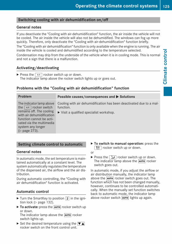
Switching cooling with air dehumidification on/off
General notesIf you deactivate the "Cooling with air-dehumidification" function, the air inside the vehicle will notbe cooled. The air inside the vehicle will also not be dehumidified. The windows can fog up morequickly. Therefore, only deactivate the "Cooling with air-dehumidification" function briefly.The "Cooling with air dehumidification" function is only available when the engine is running. The airinside the vehicle is cooled and dehumidified according to the temperature selected.Condensation may drip from the underside of the vehicle when it is in cooling mode. This is normaland not a sign that there is a malfunction.
Activating/deactivatingX Press the¿ rocker switch up or down.The indicator lamp above the rocker switch lights up or goes out.
Problems with the "Cooling with air dehumidification" function
Problem Possible causes/consequences andM Solutions
The indicator lampabovethe¿ rocker switchremains off. The coolingwith air dehumidificationfunction cannot be acti-vated via the multimediasystem any longer(Y page 273).
Cooling with air dehumidification has been deactivated due to a mal-function.X Visit a qualified specialist workshop.
Setting climate control to automatic
General notesIn automaticmode, the set temperature ismain-tained automatically at a constant level. Thesystemautomatically regulates the temperatureof the dispensed air, the airflow and the air dis-tribution.During automatic controlling, the "Cooling withair dehumidification" function is activated.
Automatic controlX Turn the SmartKey to position2 in the igni-tion lock (Y page 132).
X To activate: press theà rocker switch upor down.The indicator lamp above theà rockerswitch lights up.
X Set the desired temperature using thewrocker switch on the front control unit.
X To switch to manual operation: press theH rocker switch up or down.
orX Press the_ rocker switch up or down.The indicator lamp above theà rockerswitch goes out.
In automatic mode, if you adjust the airflow orair distribution manually, the indicator lampabove theà rocker switch goes out. Thefunction which has not been changed manually,however, continues to be controlled automati-cally. When the manually set function switchesback to automatic mode, the indicator lampabove rocker switchà lights up again.
Operating the climate control systems 125
Climatecontrol

Adjusting the climate mode settingsIn automatic mode you can select the followingairflow settings for the driver's and front-passenger areas:FOCUS high airflow, slightly cooler settingMEDIUM medium airflow, standard settingDIFFUSE low airflow, slightly warmer and draft-
free settingX To set: set the climate mode using the mul-timedia system (Y page 272).
Setting the temperatureDual-zone automatic climate control: differenttemperatures can be set for the driver's andfront-passenger sides.X Turn the SmartKey to position2 in the igni-tion lock (Y page 132).
X To increase or reduce: press rocker switchw up or down.Only change the temperature setting in smallincrements. Start at 72 ‡ (22 †).
Setting the air distribution
Air distribution settings¯ Directs air through the defroster ventsP Directs air through the center and side air
ventsO Directs air through the footwell air ventsS Directs air through the center, side and
footwell ventsa Directs air through the defroster and
footwell vents_ Directs air through the defroster, center,
side and footwell ventsb Directs air through the defroster, center
and side air ventsW Sets the air distribution to automatic
SettingX Turn the SmartKey to position2(Y page 132).
X Press the_ rocker switch up or down.The various air distribution settings appear inthe multimedia system.
Setting the airflowX Turn the SmartKey to position2 in the igni-tion lock (Y page 132).
X To increase or reduce: press rocker switchH up or down.
Activating or deactivating the syn-chronization function
General notesClimate control can be set centrally using thesynchronization function. The temperature set-ting is adopted for the front-passenger side.
Activating/deactivatingX Press rocker switch0 up or down.The indicator lamp above rocker switch0lights up or goes out.
orX Activate or deactivate the "Synchronization"function using the multimedia system(Y page 126).
The synchronization function deactivates if thesettings for the front-passenger side arechanged.
Defrosting the windshield
General notesYou can use this function to defrost the wind-shield or to clear a fogged up windshield or frontside windows on the inside.Switch off the "Windshield defrosting" functionas soon as the windshield is clear again.
Switching the "Windshield defrosting"function on or offX Turn the SmartKey to position2 in the igni-tion lock (Y page 132).
X To switch on:press rocker switch¬ onthe front control unit up or down.The indicator lamp above the¬ rockerswitch lights up. The current climate controlsettings are deactivated.
126 Operating the climate control systemsClimatecontrol
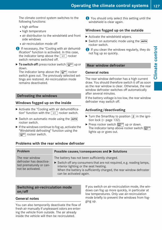
The climate control system switches to thefollowing functions:Rhigh airflowRhigh temperatureRair distribution to the windshield and frontside windowsRair-recirculation mode offi If necessary, the "Cooling with air dehumid-ification" function is activated. In this case,the indicator lamp above the¿ rockerswitch remains switched off.
X To switchoff: press rocker switch¬ up ordown.The indicator lamp above the¬ rockerswitch goes out. The previously selected set-tings are restored. Air-recirculation moderemains deactivated.
Defrosting the windows
Windows fogged up on the insideX Activate the "Cooling with air dehumidifica-tion" function with the¿ rocker switch.
X Switch on automatic mode using theÃrocker switch.
X If thewindows continue to fog up, activate the"Windshield defrosting" function using the¬ rocker switch.
i You should only select this setting until thewindshield is clear again.
Windows fogged up on the outsideX Activate the windshield wipers.X Switch on automatic mode using theÃrocker switch.i If you clean the windows regularly, they donot fog up so quickly.
Rear window defroster
General notesThe rear window defroster has a high currentdraw. You should therefore switch it off as soonas the rear window is clear. Otherwise, the rearwindow defroster switches off automaticallyafter several minutes.If the battery voltage is too low, the rear windowdefroster may switch off.
Activating/deactivatingX Turn the SmartKey to position2 in the igni-tion lock (Y page 132).
X Press rocker switch¤ up or down.The indicator lamp above rocker switch¤lights up or goes out.
Problems with the rear window defroster
Problem Possible causes/consequences andM Solutions
The rear windowdefroster has deactiva-ted prematurely or can-not be activated.
The battery has not been sufficiently charged.X Switch off any consumers that are not required, e.g. reading lamps,interior lighting or the seat heating.When the battery is sufficiently charged, the rear window defrostercan be activated again.
Switching air-recirculation modeon/off
General notesYou can also temporarily deactivate the flow offresh air manually if unpleasant odors are enter-ing the vehicle from outside. The air alreadyinside the vehicle will then be recirculated.
If you switch on air-recirculation mode, the win-dows can fog up more quickly, in particular atlow temperatures. Only use air-recirculationmode briefly to prevent the windows from fog-ging up.
Operating the climate control systems 127
Climatecontrol

Activating/deactivatingX Turn the SmartKey to position2 in the igni-tion lock (Y page 132).
X To activate: press rocker switchg up ordown.The indicator lamp above rocker switchglights up.
Air-recirculation mode switches on automati-cally:Rat high outside temperaturesRin a tunnel (vehicles with a navigation systemonly)
The indicator lamp above theg rockerswitch is not lit when automatic air-recirculationmode is activated. Outside air is added afterabout 30 minutes.X To deactivate: press theg rocker switchup or down.The indicator lamp above theg rockerswitch goes out.
Air-recirculation mode deactivates automati-cally:Rafter approximately five minutes at outsidetemperatures below approximately 41 ‡(5 †)Rafter approximately five minutes if coolingwith air dehumidification is deactivatedRafter approximately 30 minutes at outsidetemperatures above approximately 41 ‡(5 †) if the "Cooling with dehumidification"function is activated
Perfume atomizer
Operating the perfume atomizer
G WARNINGIf children open the vial, they could drink theperfume or it could come into contact withtheir eyes. There is a risk of injury. Therefore,do not leave children unsupervised in the vehi-cle.If the perfume liquid has been drunk, consulta doctor. If perfume comes into contact withyour eyes or skin, rinse the eyes with cleanwater. If you continue to experience difficul-ties, consult a doctor.
H Environmental noteFull vials must not be dis-posed of with householdwaste. They must be collec-ted separately and recycledto protect the environment.
Dispose of full vials in anenvironmentally responsiblemanner and take them to aharmful substance collec-tion point.
: Vial lid; VialThe perfume atomizer helps to improve drivingcomfort.Via the multimedia system you can:Rswitch the perfume atomizer on/off(Y page 272)Rregulate the perfume intensity (Y page 272)The following conditions can affect your percep-tion of the perfume intensity:Roperating mode of the climate control systemRinterior temperatureRtime of year or dayRair humidityRphysiological condition of occupants, e.g. fati-gue or hunger
The perfume atomizer is active only when theglove box is closed.The perfume atomizer is provided with a pre-fil-led vial. You can also choose from a variety offilled perfume vials and an empty vial which youcan fill yourself.If you refill an empty perfume vial, observe theseparate information sheet attached to the vial.
128 Operating the climate control systemsClimatecontrol

! If you do not use genuine Mercedes-Benzinterior perfumes, observe the manufactur-ers' safety notices on the perfume packaging.
Do not refill the pre-filled perfume vial when it isempty. Dispose of the used vial after use.X To insert the perfume vial: open the glovebox (Y page 279).
X Slide the perfume vial into the holder as far asit will go.
X To remove the perfume vial: pull out theperfume vial.
X To refill the perfume vial: unscrew the lid ofthe empty perfume vial to refill it yourself.
X Fill the perfume vial with a maximum of0.5 fl. oz. (15 ml) of the desired liquid per-fume.
X Screw the lid back on to the vial.
! Only refill the vial when you are outside thevehicle. Otherwise, liquid perfume could dripinto the interior and contaminate it.
Always refill the empty refillable vial with thesame perfume. Otherwise, you might not ach-ieve optimum results from the perfume atom-izer.
Problems with the perfume atomizer
Problem Possible causes/consequences andM Solutions
The vehicle interior is notperfumed although theperfume atomizer is acti-vated.
The perfume vial has not been pushed into the holder as far as it willgo.X Slide the perfume vial into the holder as far as it will go.
The perfume vial is not filled sufficiently.X Pre-filled vials: dispose of the empty vial.X Use a new pre-filled vial.X Refillable vials: fill the perfume vial with a maximum of 0.5 fl. oz.(15 ml) of the same perfume.
The perfume atomizer is faulty.X Have the perfume atomizer checked at a qualified specialist work-shop.
IonizationIonization is used to purify the air in the vehicleinterior and attain an improved interior climate.The ionization of the interior air is odorless andcannot be perceived directly in the vehicle inte-rior.You can switch ionization on or off using themultimedia system (Y page 273).Ionization can only be operated when the auto-matic climate control is switched on. The side airvent on the driver's side must be open.
Air vents
Important safety notes
G WARNINGVery hot or very cold air can flow from the airvents. This could result in burns or frostbite inthe immediate vicinity of the air vents. Thereis a risk of injury.Make sure that all vehicle occupants alwaysmaintain a sufficient distance to the air out-
Air vents 129
Climatecontrol
Z

lets. If necessary, redirect the airflow toanother area of the vehicle interior.
In order to ensure the direct flow of fresh airthrough the air vents into the vehicle interior,please observe the following notes:Rkeep the air inlet between the windshield andthe hood free of blockages, such as ice, snowor leaves.Rnever cover the air vents or air intake grilles inthe vehicle interior.
Setting the air ventsAir vents are located:Ron the left and right-hand side of the dash-boardRin the middle of the dashboardRin the rear center console, depending on theequipment installed
Side air vent (example): Side window defroster vent; Side air vent, left= Control for left side air ventX To open or close: turn control= to thecounter-clockwise or clockwise as far as it willgo.
X To adjust the air direction: hold side airvent; by control= and move it up or downor to the left or right.
Adjusting the rear air vents (see the DigitalOperator's Manual).
130 Air ventsClimatecontrol

Notes on breaking-in a new vehicle
Important safety notesThe sensor system of some driving and drivingsafety systems adjusts automatically while acertain distance is being driven after the vehiclehas been delivered or after repairs. Full systemeffectiveness is not reached until the end of thisteach-in procedure.New and replaced brake pads and discs onlyreach their optimum braking effect after severalhundred kilometers of driving. Compensate forthis by applying greater force to the brake pedal.
The first 1000 miles (1500 km)The more you look after the engine when it isnew, the more satisfied you will be with its per-formance in the future.RYou should therefore drive at varying vehicleand engine speeds for the first 1000 miles(1500 km).RAvoid heavy loads, e.g. driving at full throttle,during this period.RWhen changing gears manually, change up ingood time, before the tachometer needle rea-chesÔ of the way to the red area of the tach-ometer.RDo not manually shift to a lower gear to brakethe vehicle.RTry to avoid depressing the accelerator pedalbeyond the pressure point (kickdown).RIdeally, for the first 1,000 miles (1,500 km),drive in program E.
After 1000 miles (1500 km), you can increasethe engine speed gradually and accelerate thevehicle to full speed.You should also observe these notes on break-ing in if the engine or parts of the drive train onyour vehicle have been replaced.Always observe the maximum permissiblespeed.
Driving
Important safety notes
G WARNINGObjects in the driver's footwell may restrictthe clearance around the pedals or block adepressed pedal. This jeopardizes the oper-ating and road safety of the vehicle. There is arisk of an accident.Stow all objects securely in the vehicle so thatthey do not get into the driver's footwell.When using floormats or carpets, make surethat they are properly secured so that they donot slip or obstruct the pedals. Do not placeseveral floormats or carpets on top of oneanother.
G WARNINGUnsuitable footwear can hinder correct usageof the pedals, e.g.:Rshoes with thick solesRshoes with high heelsRslippersThere is a risk of an accident.Wear suitable footwear to ensure correctusage of the pedals.
G WARNINGIf you switch off the ignition while driving,safety-relevant functions are only availablewith limitations, or not at all. This could affect,for example, the power steering and the brakeboosting effect. You will require considerablymore effort to steer and brake. There is a riskof an accident.Do not switch off the ignition while driving.
G WARNINGIf the parking brake has not been fullyreleased when driving, the parking brake can:Roverheat and cause a fireRlose its hold function.There is a risk of fire and an accident. Releasethe parking brake fully before driving off.
Driving 131
Drivingandparking
Z

! Do not warm up the engine with the vehiclestationary. Drive off immediately. Avoid highengine speeds and driving at full throttle untilthe engine has reached its operating temper-ature.Only shift the automatic transmission to thedesired drive position when the vehicle is sta-tionary.Where possible, avoid spinning the drivewheels when pulling away on slippery roads.You could otherwise damage the drive train.
Key positions
SmartKey
g To remove the SmartKey1 Power supply for some consumers, such as
the windshield wipers2 Ignition (power supply for all consumers)
and drive position3 To start the engine
i The SmartKey can be turned in the ignitionlock even if it is not the correct SmartKey forthe vehicle. The ignition is not switched on.The engine cannot be started.
Start/Stop button
General notesWhen you insert the Start/Stop button into theignition lock, the system needs approximatelytwo seconds recognition time. You can then usethe Start/Stop button.Pressing the Start/Stop button several times insuccession corresponds to the different Smart-Key positions in the ignition lock. This is only thecase if you are not depressing the brake pedal.
If you depress the brake pedal and press theStart/Stop button, the engine starts immedi-ately.A check which periodically establishes a radioconnection between the vehicle and the Smart-Key determines whether a valid SmartKey is inthe vehicle. This occurs, for example, whenstarting the engine.To start the vehicle without actively using theSmartKey:Rthe Start/Stop buttonmust be inserted in theignition lock.Rthe SmartKey must be in the vehicle.Rthe vehicle must not be locked with theSmartKey or KEYLESS-GO. (Y page 78)
Do not keep the SmartKey:Rwith electronic devices, e.g. a mobile phoneor another SmartKey.Rwith metallic objects, e.g. coins or metal foil.Rinside metallic objects, e.g. a metal case.This can affect the functionality of the Smart-Key.If you lock the vehicle with the SmartKey remotecontrol or with KEYLESS-GO, after a short time:Ryou will not be able to switch on the ignitionwith the Start/Stop button.Ryou will no longer be able to start the enginewith the Start/Stop button until the vehicle isunlocked again.
If you lock the vehicle centrally using the buttonon the front door (Y page 83), you can continueto start the engine with the Start/Stop button.The engine can be switched off while the vehicleis in motion by pressing and holding the Start/Stop button for three seconds. This functionoperates independently of the ECO start/stopautomatic engine switch-off function.
132 DrivingDrivingandparking

Key positions with the Start/Stop button
: Start/Stop button; Ignition lockAs soon as the ignition is switched on, all theindicator lamps in the instrument cluster lightup. Warning and indicator lamps: see(Y page 256).If Start/Stop button: has not yet beenpressed, this corresponds to the SmartKeybeing removed from the ignition.X To switch on the power supply: pressStart/Stop button: once.The power supply is switched on. You can nowactivate the windshield wipers, for example.
The power supply is switched off again if:Rthe driver's door is opened andRyou press Start/Stop button: twicewhen inthis position
X To switch on the ignition: press Start/Stopbutton: twice.The ignition is switched on.
The ignition is switched off again if:Ryou do not start the engine from this positionwithin 15 minutesRyou press Start/Stop button: once when inthis position
The power supply is switched off again if:Rthe driver's door is opened andRyou press Start/Stop button: once when inthis position
Removing the Start/Stop buttonYou can remove the Start/Stop button from theignition lock and start the vehicle as normalusing the SmartKey.It is possible to switch between Start/Stop but-ton mode and key operation only when thetransmission is in positionj.
X Remove Start/Stop button: from ignitionlock;.
You do not have to remove the Start/Stop but-ton from the ignition lock when you leave thevehicle. You should, however, always take theSmartKey with you when leaving the vehicle. Aslong as the SmartKey is in the vehicle:Rthe vehicle can be started using the Start/Stop buttonRthe electrically powered equipment can beoperated
Starting the engine
Important safety notes
G WARNINGIf children are left unsupervised in the vehicle,they could:Ropen the doors, thus endangering otherpeople or road users.Rget out and disrupt traffic.Roperate the vehicle's equipment.Additionally, children could set the vehicle inmotion if, for example, they:Rrelease the parking brake.Rshifting the automatic transmission out ofpark position PRStart the engine.There is a risk of an accident and injury.When leaving the vehicle, always take theSmartKeywith you and lock the vehicle. Neverleave children or animals unattended in thevehicle. Always keep the SmartKey out ofreach of children.
G WARNINGCombustion engines emit poisonous exhaustgases such as carbon monoxide. Inhalingthese exhaust gases leads to poisoning. Thereis a risk of fatal injury. Therefore never leavethe engine running in enclosed spaces with-out sufficient ventilation.
Driving 133
Drivingandparking
Z

G WARNINGFlammable materials introduced throughenvironmental influence or by animals canignite if in contact with the exhaust system orparts of the engine that heat up. There is a riskof fire.Carry out regular checks to make sure thatthere are no flammable foreign materials inthe engine compartment or in the exhaustsystem.
General notesVehicles with a gasoline engine: the catalyticconverter is preheated for up to 30 secondsafter a cold start. The sound of the engine maychange during this time.
Automatic transmissionX Shift the transmission to positionj(Y page 141).The transmission position indicator on themultifunction display showsj(Y page 142).
i You can start the engine in transmissionpositionj andi.
Starting procedure with the SmartKeyTo start the engine using the SmartKey insteadof the Start/Stop button, pull the Start/Stopbutton out of the ignition lock.X To start a diesel engine: turn the SmartKeyto position2 in the ignition lock(Y page 132).The% preglow indicator lamp in the instru-ment cluster lights up.
X Turn the SmartKey to position3 in the igni-tion lock (Y page 132) and release it as soonas the engine is running.i Vehicles with a diesel engine: you canstart the engine without preglow if the engineis warm.
If the engine will not start:X Remove the SmartKey from the ignition lock.X Reinsert the SmartKey into the ignition lockafter a short waiting period.
X Turn the SmartKey to position2 in the igni-tion lock (Y page 132).The indicator lamps in the instrument clusterlight up (Y page 256).
X Turn the SmartKey to position3 in the igni-tion lock (Y page 132) and release it as soonas the engine is running.
Starting procedure with the Start/StopbuttonThe Start/Stop button is only available on vehi-cles with KEYLESS-GO or the KEYLESS-GO startfunction.The Start/Stop button can be used to start thevehiclemanually without inserting the SmartKeyinto the ignition lock. The Start/Stop buttonmust be inserted in the ignition lock and theSmartKey must be in the vehicle. This mode forstarting the engine operates independently ofthe ECO start/stop automatic engine start func-tion.You can start the engine if a valid SmartKey is inthe vehicle. Switch off the engine and alwaystake the SmartKey with you when leaving thevehicle, even if you only leave it for a short time.Pay attention to the important safety notes.X Depress the brake pedal and keep itdepressed.
X Press the Start/Stop button once(Y page 133).Vehicleswith a gasoline engine: the enginestarts.Vehicles with a diesel engine: preglow isactivated and the engine starts.
Starting procedure via smartphoneObserve the important safety notes on startingthe engine (Y page 133).You can also start your engine via your smart-phone from outside the vehicle. In this case, thepreviously selected climate control setting isactivated. In this way you can cool or heat theinterior of the vehicle before starting the jour-ney.Only start the engine via your smartphone if it issafe to start and run the engine where your vehi-cle is parked.Observe the legal stipulations in the area whereyour vehicle is parked. Engine start via smart-phone may be limited to certain countries orregions.
134 DrivingDrivingandparking

You can execute amaximum of two consecutivestarting attempts via your smartphone. If youpress the start/stop button or insert the Smart-Key into the ignition lock, you can carry out twomore starting attempts with your smartphone.The engine runs for ten minutes when startingwith the smartphone.Once you have started the engine, you canswitch the engine off via your smartphone at anytime.You can only start the engine via your smart-phone if:Rthe SmartKey is in the ignition lockRpark positionj is selectedRthe accelerator pedal is not depressedRthe anti-theft alarm system is not activatedRthe panic alarm is not activatedRthe hazard warning lamps are switched offRthe hood is closedRthe doors are closed and lockedRthe windows and sliding sunroof are closedAlso make sure that:Rthe fuel tank is sufficiently filledRthe starter battery has been sufficientlycharged
G WARNINGLimbs could be crushed or trapped if theengine is started unintentionally during ser-vice or maintenance work. There is a risk ofinjury.Always secure the engine against uninten-tional starting before carrying out mainte-nance or repair work.
Make sure that the engine cannot be started viayour smartphone before carrying out mainte-nance or repairs. You can prevent an enginestart via your smartphone, for example, if you:Rswitch on the hazard warning lampsRdo not lock the doorsRopen a side windowRopen the sliding sunroof
Pulling away
General notes
G WARNINGIf the engine speed is above the idling speedand you engage transmission position D or R,the vehicle could pull away suddenly. There isa risk of an accident.When engaging transmission position D or R,always firmly depress the brake pedal and donot simultaneously accelerate.
Depress the accelerator carefully when pullingaway.The vehicle locks centrally once you have pulledaway. The locking knobs in the doors drop down.You can open the doors from the inside at anytime.You can also deactivate the automatic lockingfeature, see the Digital Operator's Manual.It is possible to shift the transmission from posi-tionj to the desired position only if youdepress the brake pedal. Only then is the park-ing lock released. If you do not depress thebrake pedal, the DIRECT SELECT lever can stillbe moved but the parking lock remainsengaged.
i Upshifts take place at higher engine speedsafter a cold start. This helps the catalytic con-verter to reach its operating temperaturemore quickly.
Information on the automatic release of theelectric parking brake (Y page 156).
Pulling away with a trailer
Driving 135
Drivingandparking
Z

To ensure that you do not roll backwards whenpulling away on an uphill slope, engage the elec-tric parking brake.X Press and hold handle:.The electric parking brake continues to brakeand prevent the vehicle from rolling back-wards.The redF (USA only) or! (Canadaonly) indicator lamp in the instrument clusterremains on.
X Depress the accelerator pedal.X As soon as the vehicle/trailer combination isheld by the driving force of the engine, releaselever:.The electric parking brake is released.The redF (USA only) or! (Canadaonly) indicator lamp in the instrument clustergoes out.
For further information on the electric parkingbrake, see (Y page 155).
Hill start assistHill start assist helps you when pulling awayforward or in reverse on an uphill gradient. Itholds the vehicle for a short time after you haveremoved your foot from the brake pedal. Thisgives you enough time to move your foot fromthe brake pedal to the accelerator pedal and todepress it before the vehicle begins to roll.
G WARNINGAfter a short time, hill start assist will no lon-ger brake your vehicle and it could roll away.There is a risk of an accident and injury.Therefore, quickly move your foot from thebrake pedal to the accelerator pedal. Neverleave the vehicle when it is held by hill startassist.
Hill start assist is not active if:Ryou are pulling away on a level road or on adownhill gradientRthe transmission is in positioniRthe electric parking brake is appliedRESP® is malfunctioning
ECO start/stop function
IntroductionThe ECO start/stop function switches theengine off automatically if the vehicle is stoppedunder certain conditions.The engine starts automatically when the driverwants to pull away again. The ECO start/stopfunction thereby helps you to reduce the fuelconsumption and emissions of your vehicle.
Important safety notes
G WARNINGIf the engine is switched off automatically andyou exit the vehicle, the engine is restartedautomatically. The vehicle may begin moving.There is a risk of accident and injury.If you wish to exit the vehicle, always turn offthe ignition and secure the vehicle againstrolling away.
General notes
: ECO start/stop displayThe ECO start/stop function is activated when-ever you start the engine using the SmartKey orthe Start/Stop button.If the engine has been switched off automati-cally by the ECO start/stop function, theèECO symbol is shown in the multifunction dis-play.Mercedes-AMG vehicles: the ECO start/stopfunction is available only in drive programs S, Cand E.
Automatic engine switch-offIf the vehicle is braked to a standstill with thetransmission inh ori, the ECO start/stopfunction switches off the engine automatically.
136 DrivingDrivingandparking

The ECO start/stop function is operationalwhen:Rthe indicator lamp in the ECO button is litgreenRthe outside temperature and the atmosphericair pressure is within the range that is suitablefor the systemRthe engine is at normal operating temperatureRthe set temperature for the vehicle interiorhas been reachedRthe battery is sufficiently chargedRthe system detects that the windshield is notfogged upwhen the air-conditioning system isswitched onRthe hood is closedRthe driver's door is closed and the driver'sseat belt is fastened
All of the vehicle's systems remain active whenthe engine is stopped automatically.The HOLD function can also be activated if theengine has been switched off automatically. It isthen not necessary to continue applying thebrakes during the automatic stop phase. Whenyou depress the accelerator pedal, the enginestarts automatically and the braking effect ofthe HOLD function is deactivated.Automatic engine switch-off can take place amaximumof four times in a row (initial stop, thenthree subsequent stops).
Automatic engine startThe engine starts automatically if:Ryou switch off the ECO start/stop function bypressing the ECO buttonRyou switch to drive program S+RMercedes-AMG vehicles: you permanentlyactivate manual gearshifting (Y page 145)Rin transmission positionh ori, the brakepedal is released and theHOLD function is notactiveRyou depress the accelerator pedalRyou engage reverse gearkRyou move the transmission out of positionjRyou unfasten your seat belt or open the driv-er's doorRthe vehicle starts to rollRthe brake system requires thisRthe temperature in the vehicle interior devi-ates from the set range
Rthe system detects moisture on the wind-shield when the air-conditioning system isswitched onRthe condition of charge of the battery is toolow
Shifting the transmission to positionj doesnot start the engine.
Deactivating or activating the ECOstart/stop function
Mercedes-AMG vehicles
X To deactivate: press ECO button:.Indicator lamp; goes out.
X To activate: press ECO button:.Indicator lamp; lights up.
If indicator lamp; is off, the ECO start/stopfunction has been switched off manually or asthe result of a malfunction. The engine will thennot be switched off automatically when the vehi-cle stops.The ECO start/stop function is deactivated, if:Ryou switch to drive program S+(Y page 139)Ryou permanently activatemanual gearshifting(Y page 145)
If you have permanently activated manual gear-shifting and then press ECO button:, the ECOstart/stop function is switched on.
Driving 137
Drivingandparking
Z

All other models X To deactivate: press ECO button:.Indicator lamp; goes out.
X To activate: press ECO button:.Indicator lamp; lights up.
If indicator lamp; is off, the ECO start/stopfunction has been deactivated manually or asthe result of a malfunction. The engine will thennot be switched off automatically when the vehi-cle stops.Selecting drive programS+ deactivates the ECOstart/stop function. If you press ECO button:,the ECO start/stop function is activated.
Problems with the engine
Problem Possible causes/consequences andM Solutions
The engine does notstart.
The HOLD function or DISTRONIC PLUS is activated.X Deactivate the HOLD function (Y page 172) or DISTRONIC PLUS(Y page 169).
X Try to start the engine again (Y page 133).
The engine does notstart. The starter motorcan be heard.
RThere is a malfunction in the engine electronics.RThere is a malfunction in the fuel supply.Before attempting to start the engine again:X Turn the SmartKey back to positionu in the ignition lock.orX Press the Start/Stop button repeatedly until all indicator lamps inthe instrument cluster go out.
X Try to start the engine again (Y page 133). Avoid excessively longand frequent attempts to start the engine as these will drain thebattery.
If the engine does not start after several attempts:X Consult a qualified specialist workshop.
The engine does notstart. The starter motorcan be heard. Thereserve fuel warninglamp is lit and the fuelgauge display is at thereserve level.
The fuel tank is empty.X Refuel the vehicle.
The engine does notstart. You cannot hearthe starter motor.
The on-board voltage is too low because the battery is too weak ordischarged.X Jump-start the vehicle (Y page 328).If the engine does not start despite attempts to jump-start it:X Consult a qualified specialist workshop.
138 DrivingDrivingandparking

Problem Possible causes/consequences andM Solutions
The starter motor was exposed to a thermal load that was too high.X Try to start the engine again (Y page 133).If the engine still does not start:X Consult a qualified specialist workshop.
Vehicles with a gasolineengine:The engine is not runningsmoothly and is misfir-ing.
There is a malfunction in the engine electronics or in a mechanicalcomponent of the engine management system.X Only depress the accelerator pedal slightly.Otherwise, non-combusted fuel may get into the catalytic converterand damage it.
X Have the cause rectified immediately at a qualified specialist work-shop.
The coolant temperaturegauge shows a valueabove 248 ‡ (120 †).
The coolant level is too low. The coolant is too hot and the engine is nolonger being cooled sufficiently.X Stop as soon as possible and allow the engine and the coolant tocool down.
X Check the coolant level (Y page 309). Observe the warning notesas you do so and add coolant if necessary.
DYNAMIC SELECT switch
Mercedes-AMG GLC 43 4MATIC
General informationSelect the drive program using the DYNAMICSELECT switch.Available drive programs:
S+ Sport Plus Particularly sporty drivingcharacteristics
S Sport Sporty driving characteris-tics
C Comfort Comfortable and economi-cal driving characteristics
E Economy Particularly economicaldriving characteristics
I Individual Individual settings
Depending on the drive program selected thefollowing vehicle characteristics will change:Rthe engine managementRthe transmission managementRthe suspensionRthe steering
Rthe availability of the ECO start/stop functionRclimate controlRthe driver assistance systemsRthe availability of gliding modeFurther information for automatic drive programcharacteristics (Y page 144).Additionally, in drive program I you can config-ure the respective vehicle characteristics usingthe multimedia system. You can find informa-tion about this in the Digital Operator's Manual.Each time you start the engine with the Smart-Key or the Start/Stop button, drive programC isactivated. For further information about startingthe engine, see (Y page 133).
DYNAMIC SELECT switch 139
Drivingandparking
Z

Selecting the drive program
X Press DYNAMIC SELECT switch: forward orback until the desired drive program is selec-ted.The status icon of the selected drive programis shown in the multifunction display.In addition, the current drive programsettingsare displayed briefly in themultimedia systemdisplay.
You can also change gear yourself using thesteering wheel paddle shifters. For further infor-mation on the manual drive program(Y page 145).
Additional settings
: ECO start/stop function (Y page 136); ESP® (Y page 70)= Suspension (Y page 174)? Permanent activation ofmanual gearshifting
(Y page 145)When you press buttons:–? the correspond-ing setting is selected. The DYNAMIC SELECTswitch setting is overwritten.If you switch to drive program I, all stored char-acteristics will be accepted. This is also the caseif you have previously pressed one of buttons:-A.
i In a few countries, the ECO start/stop func-tion is deactivated at the factory due to theavailable fuel grade. In this case, the ECOstart/stop function is not available in anydrive program, regardless of the display in themultimedia system display.
All other modelsUse the DYNAMIC SELECT switch to change thedrive program.Depending on the drive program selected thefollowing vehicle characteristics will change:Rthe drive (engine and transmission manage-ment)Rthe suspension.Rthe steering.Rthe availability of the ECO start/stop functionRthe climate control
- the climate control settings- the rear window defroster operation period- the performance of the seat heating
Each time you start the engine with the Smart-Key or the Start/Stop button, drive programC isactivated. For further information about startingthe engine, see (Y page 133).
X Push DYNAMIC SELECT switch: forward orback until the desired drive program is selec-ted.The status icon of the selected drive programis shown in the multifunction display.In addition, the current drive programsettingsare displayed briefly in themultimedia systemdisplay.i In a few countries, the ECO start/stop func-tion is deactivated at the factory due to theavailable fuel grade. In this case, the ECOstart/stop function is not available in any
140 DYNAMIC SELECT switchDrivingandparking

drive program, regardless of the display in themultimedia system display.
Available drive programs:
I Individual Individual settings
S+ Sport Plus Particularly sporty drivingcharacteristics
S Sport Sporty driving characteris-tics
C Comfort Comfortable and economi-cal driving characteristics
E Economy Particularly economicaldriving characteristics
Additional information for drive programs(Y page 144).You can also change gear yourself using thesteering wheel paddle shifters. For further infor-mation on the manual drive program(Y page 145).
Automatic transmission
Important safety notes
G WARNINGIf the engine speed is above the idling speedand you engage transmission position D or R,the vehicle could pull away suddenly. There isa risk of an accident.When engaging transmission position D or R,always firmly depress the brake pedal and donot simultaneously accelerate.
G WARNINGThe automatic transmission switches to neu-tral positionNwhen you switch off the engine.The vehicle may roll away. There is a risk of anaccident.After switching off the engine, always switchto parking positionP. Prevent the parked vehi-cle from rolling away by applying the parkingbrake.
DIRECT SELECT lever
Overview of transmission positions
j Park position with parking lockk Reverse geari Neutralh DriveThe DIRECT SELECT lever is on the right of thesteering column.The DIRECT SELECT lever always returns to itsoriginal position. The current transmission posi-tionj,k,i orh is shown in the transmis-sion position display on the multifunction dis-play (Y page 142).
Selecting park position! If the engine speed is too high or the vehicleis coasting, do not shift the automatic trans-mission directly fromh tok, fromk tohor directly toj. Otherwise, the automatictransmission may be damaged.
X Push theDIRECTSELECT lever in the directionof arrowj.
Engaging park position automaticallyPark positionj is automatically engaged if:Ryou switch off the engine using the SmartKeyand remove the SmartKeyRyou switch off the engine using the SmartKeyor using the Start/Stop button and open thedriver's door or front-passenger doorRyou open the driver's door when the vehicle isstationary or when driving at a very low speedand the transmission is in positionh ork
Under certain conditions, the automatic trans-mission shifts automatically to transmissionpositionj if the HOLD function or DISTRONIC
Automatic transmission 141
Drivingandparking
Z
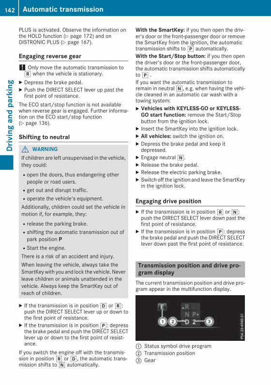
PLUS is activated. Observe the information onthe HOLD function (Y page 172) and onDISTRONIC PLUS (Y page 167).
Engaging reverse gear! Only move the automatic transmission tok when the vehicle is stationary.
X Depress the brake pedal.X Push the DIRECT SELECT lever up past thefirst point of resistance.
The ECO start/stop function is not availablewhen reverse gear is engaged. Further informa-tion on the ECO start/stop function(Y page 136).
Shifting to neutral
G WARNINGIf children are left unsupervised in the vehicle,they could:Ropen the doors, thus endangering otherpeople or road users.Rget out and disrupt traffic.Roperate the vehicle's equipment.Additionally, children could set the vehicle inmotion if, for example, they:Rrelease the parking brake.Rshifting the automatic transmission out ofpark position PRStart the engine.There is a risk of an accident and injury.When leaving the vehicle, always take theSmartKeywith you and lock the vehicle. Neverleave children or animals unattended in thevehicle. Always keep the SmartKey out ofreach of children.
X If the transmission is in positionh ork:push the DIRECT SELECT lever up or down tothe first point of resistance.
X If the transmission is in positionj: depressthe brake pedal and push the DIRECT SELECTlever up or down to the first point of resist-ance.
If you switch the engine off with the transmis-sion in positionk orh, the automatic trans-mission shifts toi automatically.
With the SmartKey: if you then open the driv-er's door or the front-passenger door or removethe SmartKey from the ignition, the automatictransmission shifts toj automatically.With the Start/Stop button: if you then openthe driver's door or the front-passenger door,the automatic transmission shifts automaticallytoj .If you want the automatic transmission toremain in neutrali, e.g. when having the vehi-cle cleaned in an automatic car wash with atowing system:X Vehicles with KEYLESS-GO or KEYLESS-GO start function: remove the Start/Stopbutton from the ignition lock.
X Insert the SmartKey into the ignition lock.X All vehicles: switch the ignition on.X Depress the brake pedal and keep itdepressed.
X Engage neutrali.X Release the brake pedal.X Release the electric parking brake.X Switch off the ignition and leave the SmartKeyin the ignition lock.
Engaging drive positionX If the transmission is in positionk ori:push the DIRECT SELECT lever down past thefirst point of resistance.
X If the transmission is in positionj: depressthe brake pedal and push the DIRECT SELECTlever down past the first point of resistance.
Transmission position and drive pro-gram displayThe current transmission position and drive pro-gram appear in the multifunction display.
: Status symbol drive program; Transmission position= Gear
142 Automatic transmissionDrivingandparking
The arrows in the transmission position displayshowhowand intowhich transmission positionsyou can shift using the DIRECT SELECT lever.If the transmission position display in the mul-tifunction display is not working, you should pullaway carefully to check whether the desiredtransmission position is engaged. Ideally, youshould select transmission positionh anddrive program E or S.
Transmission positions
B Park positionThis prevents the vehicle from rollingaway when stopped.Only shift the transmission into posi-tionj (Y page 141) when the vehi-cle is stationary. The parking lockshould not be used as a brake whenparking. Always apply the electronicparking brake in addition to the park-ing lock in order to secure the vehi-cle.Park positionj is automaticallyengaged if:Ryou switch off the engine using theSmartKey and remove the Smart-KeyRyou switch off the engine using theSmartKey or using the Start/Stopbutton and open the driver's dooror front-passenger doorRyou open the driver's door whenthe vehicle is stationary or whendriving at a very low speed and thetransmission is in positionh ork
In the event of a malfunction of thevehicle's electronics, the transmis-sion may lock in positionj. Havethe vehicle electronics checkedimmediately at a qualified specialistworkshop.
C Reverse gearYou can only shift the transmissioninto positionk when the vehicle isstationary (Y page 142).
A NeutralDo not shift the transmission toiwhile driving. Otherwise, the auto-matic transmission could be dam-aged.No power is transmitted from theengine to the drive wheels.Releasing the brake pedal will allowyou tomove the vehicle freely, e.g. topush it or tow it.If ESP® is deactivated or faulty: shiftthe transmission to positioni if thevehicle is in danger of skidding, e.g.on icy roads.If you switch the engine off with thetransmission in positionk orh,the automatic transmission shifts toi automatically.
! Coasting in neutrali maycause damage to the drive train.
7 DriveThe automatic transmission changesgear automatically. All forward gearsare available.
Driving tips
Changing gearThe automatic transmission shifts through theindividual gears automatically when it is in trans-mission positionh. This automatic gear shift-ing behavior is determined by:Rthe selected drive programRthe position of the accelerator pedalRthe road speed
Accelerator pedal positionYour style of driving influences how the auto-matic transmission shifts gear:Rlittle throttle: early upshiftsRmore throttle: late upshifts
Double-clutch functionWhen shifting down, the double-clutch functionis active regardless of the currently selecteddrive program. The double-clutch function
Automatic transmission 143
Drivingandparking
Z
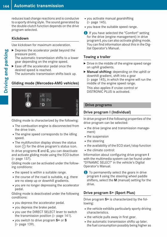
reduces load change reactions and is conduciveto a sporty driving style. The sound generated bythe double-clutch function depends on the driveprogram selected.
KickdownUse kickdown for maximum acceleration.X Depress the accelerator pedal beyond thepressure point.The automatic transmission shifts to a lowergear depending on the engine speed.
X Ease off the accelerator pedal once thedesired speed is reached.The automatic transmission shifts back up.
Gliding mode (Mercedes-AMG vehicles)
Gliding mode is characterized by the following:RThe combustion engine is disconnected fromthe drive train.RThe engine speed corresponds to the idlingspeed.RThe multifunction display shows the statusicon: for the drive program's status icon.
In drive programs E and C, you can deactivateand activate gliding mode using the ECO button(Y page 137).Gliding mode can be activated under the follow-ing conditions:Rthe speed is within a suitable range.Rthe course of the road is suitable, e.g. thereare no steep up or downhill gradients.Ryou are no longer depressing the acceleratorpedal.
Gliding mode is deactivated under the followingconditions:Ryou depress the accelerator pedal.Ryou depress the brake pedal.Ryou use the DIRECT SELECT lever to switchthe transmission position (Y page 141).Ryou switch to drive program S+ or S(Y page 139).
Ryou activate manual gearshifting(Y page 145).Ryou leave the suitable speed range.
i If you have selected the "Comfort" settingfor the drive (engine management) in driveprogram I, you can also activate glidingmode.You can find information about this in the Dig-ital Operator's Manual.
Towing a trailerX Drive in the middle of the engine speed rangeon uphill gradients.
X Manual shifting: depending on the uphill ordownhill gradient, shift into a gear(Y page 145), in which the engine will run themiddle of the engine speed range.This also applies if cruise control orDISTRONIC PLUS is activated.
Drive programs
Drive program I (Individual)In drive program I the following properties of thedrive program can be selected:Rthe drive (engine and transmission manage-ment)Rthe suspensionRthe steeringRthe availability of the ECO start/stop functionRthe climate control:Information about configuring drive program Iwith the multimedia system can be found under"DYNAMIC SELECT" in the vehicle's DigitalOperator's Manual.
i To permanently select the gears in driveprogram I using the steering wheel paddleshifters, select theM (manual) setting for thedrive.
Drive program S+ (Sport Plus)Drive program S+ is characterized by the fol-lowing:Rthe vehicle exhibits particularly sporty drivingcharacteristics.Rthe vehicle pulls away in first gear.Rthe automatic transmission shifts up later.the fuel consumption possibly being higher as
144 Automatic transmissionDrivingandparking

a result of the later automatic transmissionshift points.Rthe suspension exhibits particularly stiffspringing and damping settings (vehicles withAIR BODY CONTROL).Rgliding mode is not available (Mercedes-AMGvehicles).Rthe ECO start/stop function is not available.
Drive program S (Sport)Drive program S is characterized by the follow-ing:Rthe vehicle exhibits sporty driving character-istics.Rthe vehicle pulls away in first gear.Rthe automatic transmission shifts up later.the fuel consumption possibly being higher asa result of the later automatic transmissionshift points.Rthe suspension exhibits particularly stiffspringing and damping settings (vehicles withAIR BODY CONTROL).Rgliding mode is not available (Mercedes-AMGvehicles).Rthe ECO start/stop function is not available.
Drive program C (Comfort)Drive program C is characterized by the follow-ing:Rthe vehicle delivers comfortable, economicalhandling characteristics.Rthe vehicle pulls away more gently in forwardand reverse gears, unless the acceleratorpedal is depressed fully.Rthe vehicle has improved driving stability, forexample on slippery road surfaces.Roptimal fuel consumption resulting from theautomatic transmission shifting up sooner.The vehicle is driven in the low engine speedrange and the wheels are less likely to spin.Rgliding mode is not available (Mercedes-AMGvehicles).
Drive program E (Economy)Drive program E is characterized by the follow-ing:Rthe vehicle exhibits comfortable, economicalhandling characteristics.Rthe vehicle pulls away more gently in forwardand reverse gears, unless the acceleratorpedal is depressed fully.Rthe vehicle has improved driving stability, forexample on slippery road surfaces.Roptimal fuel consumption resulting from theautomatic transmission shifting up sooner.The vehicle is driven in the low engine speedrange and the wheels are less likely to spin.Rduring deceleration, the engine is disconnec-ted from the drive train. The vehicle useskinetic energy and consumes less fuel.Rthe cooling and heating output of the climatecontrol system has been reduced.
Manual gear shifting
General notesYou can change gear yourself using the steeringwheel paddle shifters. The transmissionmust bein positionh to do this.Depending on which steering wheel paddleshifter is pulled, the automatic transmissionimmediately shifts into the next gear down orup, if permitted.Mercedes-AMG vehicles: to use manual shift-ing, you have two options:Rtemporary settingRpermanent settingIf you activate manual gearshifting, the multi-function display will show the current gearinstead of transmission positionh.If you deactivate manual gearshifting, the gearswill be shifted automatically again.
Automatic transmission 145
Drivingandparking
Z
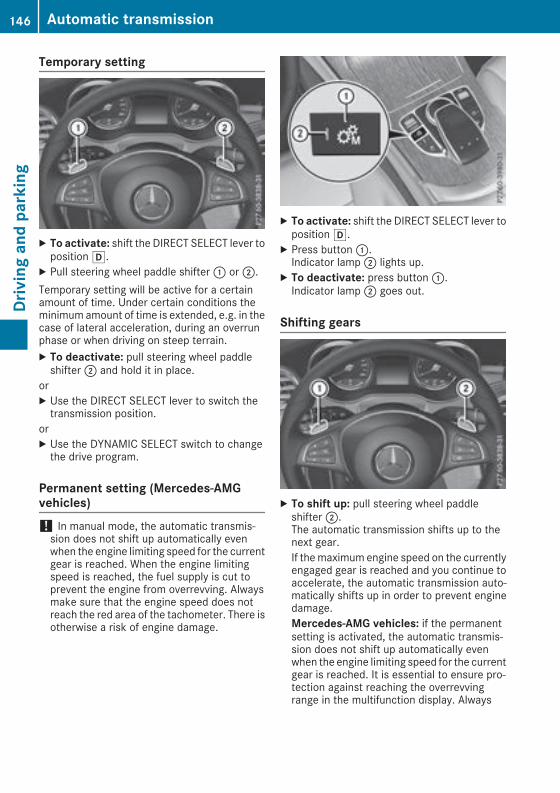
Temporary setting
X To activate: shift the DIRECT SELECT lever topositionh.
X Pull steering wheel paddle shifter: or;.Temporary setting will be active for a certainamount of time. Under certain conditions theminimum amount of time is extended, e.g. in thecase of lateral acceleration, during an overrunphase or when driving on steep terrain.X To deactivate: pull steering wheel paddleshifter; and hold it in place.
orX Use the DIRECT SELECT lever to switch thetransmission position.
orX Use the DYNAMIC SELECT switch to changethe drive program.
Permanent setting (Mercedes-AMGvehicles)! In manual mode, the automatic transmis-sion does not shift up automatically evenwhen the engine limiting speed for the currentgear is reached. When the engine limitingspeed is reached, the fuel supply is cut toprevent the engine from overrevving. Alwaysmake sure that the engine speed does notreach the red area of the tachometer. There isotherwise a risk of engine damage.
X To activate: shift the DIRECT SELECT lever topositionh.
X Press button:.Indicator lamp; lights up.
X To deactivate: press button:.Indicator lamp; goes out.
Shifting gears
X To shift up: pull steering wheel paddleshifter;.The automatic transmission shifts up to thenext gear.If themaximum engine speed on the currentlyengaged gear is reached and you continue toaccelerate, the automatic transmission auto-matically shifts up in order to prevent enginedamage.Mercedes-AMG vehicles: if the permanentsetting is activated, the automatic transmis-sion does not shift up automatically evenwhen the engine limiting speed for the currentgear is reached. It is essential to ensure pro-tection against reaching the overrevvingrange in the multifunction display. Always
146 Automatic transmissionDrivingandparking

make sure that the engine speed does notreach the red area of the tachometer.
X To shift down: pull steering wheel paddleshifter:.The automatic transmission shifts down tothe next gear.Automatic down shifting occurs when coast-ing.If the engine exceeds the maximum enginespeed when shifting down, the automatictransmission protects against engine damageby not shifting down.
Shift recommendation
The gearshift recommendations assist you inadopting an economical driving style. The rec-ommended gear is shown in the multifunctiondisplay.X Shift to recommended gear; according togearshift recommendation: when shown inthe multifunction display of the instrumentcluster.
Protection against reaching the over-revving range (Mercedes-AMG vehicles)! In manual mode, the automatic transmis-sion does not shift up automatically evenwhen the engine limiting speed for the current
gear is reached. When the engine limitingspeed is reached, the fuel supply is cut toprevent the engine from overrevving. Alwaysmake sure that the engine speed does notreach the red area of the tachometer. There isotherwise a risk of engine damage.
Before the engine speed reaches the red area,an upshift indicator will be shown in the multi-function display.X When message: appears in the multifunc-tion display, pull the right-hand steeringwheel paddle shifter.
KickdownX For maximum acceleration, depress theaccelerator pedal beyond the pressure point.The automatic transmission shifts to a lowergear depending on the engine speed.
X Shift back up once the desired speed isreached.
During kickdown, you cannot shift gears usingthe steering wheel paddle shifters.If you apply full throttle, the automatic trans-mission shifts up to the next gear when themaximum engine speed is reached. This pre-vents the engine from overrevving.Mercedes-AMG vehicles: kickdown is onlypossible in the temporary setting.
Automatic transmission 147
Drivingandparking
Z

Problems with the transmission
Problem Possible causes/consequences andM Solutions
The transmission hasproblems shifting gear.
The transmission is losing oil.X Have the transmission checked at a qualified specialist workshopimmediately.
The acceleration abilityis deteriorating.The transmission no lon-ger changes gear.
The transmission is in emergency mode.It is only possible to shift into second gear and reverse gear.X Stop the vehicle.X Shift the transmission to positionj.X Switch off the engine.X Wait at least ten seconds before restarting the engine.X Shift the transmission to positionh ork.Ifh is selected, the transmission shifts to second gear; ifk isselected, the transmission shifts to reverse gear.
X Have the transmission checked at a qualified specialist workshopimmediately.
Transfer caseThis section is only valid for vehicles with 4-wheel drive (4MATIC). Power is always trans-mitted to both axles.
! Performance tests may only be carried outon a 2-axle dynamometer. The brake systemor transfer case could otherwise be damaged.Contact a qualified specialist workshop for aperformance test.
! Since ESP® engages automatically, the igni-tion must be switched off (the SmartKey orStart/Stop button must be in positiong or1) ifRthe electrical parking brake is being testedusing a dynamometerRthe vehicle is being towed with only oneaxle raised (not permitted for vehicles with4MATIC)
Otherwise, the brake system can be dam-aged.
! Vehicles with 4MATIC must not be towedwith either the front or the rear axle raised, asdoing so will damage the transmission.
Refueling
Important safety notes
G WARNINGFuel is highly flammable. If you handle fuelincorrectly, there is a risk of fire and explo-sion.You must avoid fire, open flames, creatingsparks and smoking. Switch off the engineand, if applicable, the auxiliary heating beforerefueling.
G WARNINGFuel is poisonous and hazardous to health.There is a risk of injury.You must make sure that fuel does not comeinto contact with your skin, eyes or clothingand that it is not swallowed. Do not inhale fuelvapors. Keep fuel away from children.If you or others come into contact with fuel,observe the following:RWash away fuel from skin immediatelyusing soap and water.RIf fuel comes into contact with your eyes,immediately rinse them thoroughly with
148 RefuelingDrivingandparking

clean water. Seek medical assistance with-out delay.RIf fuel is swallowed, seek medical assis-tance without delay. Do not induce vomit-ing.RImmediately change out of clothing whichhas come into contact with fuel.
G WARNINGElectrostatic buildup can create sparks andignite fuel vapors. There is a risk of fire andexplosion.Always touch the vehicle body before openingthe fuel filler flap or touching the fuel pumpnozzle. Any existing electrostatic buildup isthereby discharged.
Do not get into the vehicle again during the refu-eling process. otherwise electrostatic chargecould build up again.
G WARNINGVehicles with a diesel engine:If you mix diesel fuel with gasoline, the flashpoint is lower than that of pure diesel fuel.When the engine is running, exhaust systemcomponents could overheat without beingnoticed. There is a risk of fire.Never refuel with gasoline. Nevermix gasolinewith diesel fuel.
! Do not use diesel to refuel vehicles with agasoline engine. Do not switch on the ignitionif you accidentally refuel with the wrong fuel.Otherwise, the fuel will enter the fuel system.Even small amounts of the wrong fuel couldresult in damage to the fuel system and theengine. Notify a qualified specialist workshopand have the fuel tank and fuel lines drainedcompletely.
! Do not use gasoline to refuel vehicles with adiesel engine. Do not switch on the ignition ifyou accidentally refuel with the wrong fuel.Otherwise, the fuel will enter the fuel system.Even small amounts of the wrong fuel couldresult in damage to the fuel system and theengine. The repair costs are high. Notify aqualified specialist workshop and have thefuel tank and fuel lines drained completely.
! Overfilling the fuel tank could damage thefuel system.
! Take care not to spill any fuel on paintedsurfaces. You could otherwise damage thepaintwork.
! Use a filter when adding fuel from a fuel can.The fuel lines and/or the fuel injection systemcould otherwise be blocked by particles fromthe fuel can.
If you overfill the fuel tank, fuel could spray outwhen the fuel pump nozzle is removed.For further information on fuel and fuel quality(Y page 364).
Refueling
General informationPay attention to the important safety notes(Y page 148).If you unlock/lock the vehicle from the outside,the fuel filler flap also unlocks/locks.The position of the fuel filler cap is displayed inthe instrument cluster8. The arrow next tothe filling pump indicates the side of the vehicle.
Opening the fuel filler flap
: To open the fuel filler flap; To insert the fuel filler cap= Tire pressure table? Instruction label for fuel type to be refueled
Refueling 149
Drivingandparking
Z

X Switch off the engine.X Remove the SmartKey from the ignition lock.or, in vehicles with KEYLESS-GO start-functionor KEYLESS‑GOX Open the driver's door.The vehicle electronics are now in positionu. This is the same as the key having beenremoved.
X Press the fuel filler flap in the direction ofarrow:.The fuel filler flap swings up.
X Turn the fuel filler cap counterclockwise andremove it.
X Insert the fuel filler cap into the holder on theinside of fuel filler flap;.
X Completely insert the filler neck of the fuelpump nozzle into the tank, hook in place andrefuel.
X Only fill the tank until the pump nozzleswitches off.
Do not add any more fuel after the pump stopsfilling for the first time. Otherwise, fuel may leakout.Vehicles with a diesel engine: the filler neck isdesigned for refueling at diesel filling pumps.
Closing the fuel filler flapX Replace the cap on the filler neck and turnclockwise until it engages audibly.
X Close the fuel filler flap.Close the fuel filler flap before locking the vehi-cle.If you are driving with the fuel filler cap open, the8 reserve fuel warning lamp flashes. A mes-sage appears in the multifunction display(Y page 242).
150 RefuelingDrivingandparking

Problems with fuel and the fuel tank
Problem Possible causes/consequences andM Solutions
Fuel is leaking from thevehicle.
G WARNINGThe fuel line or the fuel tank is faulty.Risk of explosion or fire.X Apply the electric parking brake.X Switch off the engine.X Remove the SmartKey from the ignition lock.or, in vehicles with KEYLESS-GO start-function or KEYLESS‑GOX Open the driver's door.The vehicle electronics are now in positionu. This is the same asthe key having been removed.
X Do not restart the engine under any circumstances.X Consult a qualified specialist workshop.
The engine does notstart.
The fuel tank of a vehicle with a diesel engine has been run completelydry.X Refuel the vehicle with at least 5.3 US qt (5 l) of diesel.X Turn the ignition on for approximately ten seconds (Y page 132).X Start the engine continuously for up to ten seconds until it runssmoothly.
If the engine does not start:X Turn the ignition on again for approximately ten seconds(Y page 132).
X Start the engine again continuously for up to ten seconds until itruns smoothly.
If the engine does not start after three attempts:X Consult a qualified specialist workshop.
The fuel filler flap cannotbe opened.
The fuel filler flap is not unlocked.X Unlock the vehicle (Y page 77).
The SmartKey battery is discharged or nearly discharged.X Unlock the vehicle using the mechanical key (Y page 79).
The fuel filler flap is unlocked, but the opening mechanism is jammed.X Consult a qualified specialist workshop.
DEF (BlueTEC vehicles only)
General notesTo function properly, BlueTEC exhaust gas after-treatment must be operated with the reducingagent DEF.
When the DEF supply drops to a minimum, theCheck Additive See Owner's Manual mes-sage is shown in the multifunction display.If you drive the vehicle faster than 10 mph(16 km/h) after topping up, the Check Addi‐tive See Owner's Manualmessage goes outafter approximately one minute.
Refueling 151
Drivingandparking
Z

When the DEF supply drops to a minimum, theRemaining Starts: 16 message is shown inthe multifunction display.The Remaining Starts: 16 message in themultifunction display indicates how many moretimes you can start the vehicle. If DEF is notrefilled, you will subsequently be unable tostart the engine.If the 10 starts display message is shown and awarning tone also sounds, then the DEF systemis malfunctioning. Have the DEF systemchecked at a qualified specialist workshop.X Add at least 1.3 gal (5.0 l) of DEF.X Switch on the ignition for at least 60 seconds.X Start the engine.
i Have the DEF tank refilled at a qualified spe-cialist workshop.
Use the special DEF refill bottle when addingDEF betweenmaintenance intervals. Contact anauthorized Mercedes-Benz Center with anyquestions or, if necessary, contact RoadsideAssistance (Y page 29).If the outside temperature is below12‡ (Ò11†)it may be difficult to top up. If DEF is frozen andthere is an active warning indicator, it may notbe possible to add DEF. Park the vehicle in awarmer place, e.g. in a garage, until DEF hasbecome fluid again. It will then be possible toadd DEF again. Alternatively, have the DEF tankrefilled at a qualified specialist workshop.Further information about BlueTEC exhaust gasaftertreatment and DEF is available at anyauthorized Mercedes-Benz Center.
Important safety notesDEF is a water-soluble fluid for the exhaust gasaftertreatment of diesel engines. It is:Rnot poisonousRcolorless and odorlessRnot flammableWhen you open the DEF container, smallamounts of ammonia vapor may be released.Ammonia vapors have a pungent odor and areparticularly irritating to the skin, to mucousmembranes and to the eyes. You may experi-ence a burning sensation in your eyes, nose andthroat. Coughing and watering of the eyes arepossible.Do not inhale ammonia vapors. Fill the DEF tankonly in well-ventilated areas.
DEF must not come into contact with your skin,eyes or clothing and must not be swallowed.Keep DEF away from children.If you or other persons come into contact withDEF, observe the following:RRinse DEF from your skin immediately withsoap and water.RIf DEF comes into contact with your eyes,immediately rinse them thoroughly with cleanwater. Seek medical assistance withoutdelay.RIf DEF has been swallowed, rinse your mouthout immediately. Drink plenty of water. Seekmedical assistance without delay.RChange out of clothing contaminated withDEF immediately.
! Only use DEF in accordance withISO 22241. Do not mix any additives withDEF, and do not dilute DEF with water. Thismay destroy the BlueTEC exhaust gas after-treatment system.
! The vehicle must be parked on level groundto fill the DEF tank. The DEF tank can only befilled as intended with the vehicle parked on alevel surface. This avoids false level readings.Filling the tank is not permitted if the vehicleis not parked on a level surface. There is adanger of overfilling, which could result indamage to components of the BlueTECexhaust gas aftertreatment.
! Rinse surfaces that have come into contactwith DEF immediately with water or removeDEF using a damp cloth and cold water. If theDEF has already crystallized, use a spongeand cold water to clean it. DEF residues crys-tallize after time and contaminate the affec-ted surfaces.
! DEF is not a fuel additive and must not beadded to the fuel tank. If DEF is added to thefuel tank, this can lead to engine damage.
Have the DEF tank refilled at a qualified special-ist workshop. However, you can also refill theDEF tank:Rat a gas station with a DEF filling pumpRwith DEF refill bottlesRwith a DEF refill canisterWhen the pump nozzle switches off automati-cally during filling at a filling pump, the DEF tankhas been completely filled. Do not fill the DEFtank any further. DEF may leak out.
152 RefuelingDrivingandparking

To avoid transporting already opened refill con-tainers in the vehicle, completely empty refillbottles or canisters when filling the DEF tank, ifpossible.For further information on DEF, see(Y page 367).
Opening/closing the DEF filler cap
X To open:switch the ignition off.X Press the fuel filler flap in the direction ofarrow:.The fuel filler flap swings up.
X Turn blue DEF filler cap; counter-clockwiseand remove it.DEF filler cap; is secured with a plasticstrip.
X To close: place DEF filler cap; on the fillerneck and turn it clockwise.
X To close the fuel filler flap, press it in thedirection of arrow:.
X Drive faster than 10 mph (16 km/h).The Refill AdBlue See Operator’s Man‐ual message goes out after approximatelyone minute.
If the Refill AdBlue See Operator’s Man‐ualmessage continues to be shown in the mul-tifunction display, you must add more DEF.
i The fuel filler flap is unlocked or lockedautomatically when you unlock or lock thevehicle.
DEF refill canisters! Do not screw the disposable hose on tootight. The disposable hose could otherwise bedamaged and DEF may leak out.
X Unscrew the cap from the opening on top ofDEF refill canister;.
X Place disposable hose: on the opening ofDEF refill canister; and screw it on clock-wise until hand-tight.Disposable hose: remains closed until youfasten disposable hose: to the DEF fillerneck of the vehicle.
X Place disposable hose: on the filler neck onthe vehicle and screw it on clockwise untilhand-tight. When you feel resistance, dispos-able hose: is sufficiently secured.
X Lift up and tip DEF refill canister;.Filling stops when the DEF tank is completelyfilled. Do not fill the DEF tank any further. DEFrefill canister; can be removed when it hasbeen only partially emptied.
X Turn disposable hose: on the filler neck ofthe vehicle counter-clockwise and remove it.
X Turn disposable hose: on the opening ofDEF refill canister; counter-clockwise andremove it.
X Reseal DEF refill canister; with the cap.DEF refill canisters are available at many gasstations or at a qualified specialist workshop.DEF refill canisters are often sold with a fillerhose. A filler hose that does not exactly fit thevehicle's DEF tank offers no protection against
Refueling 153
Drivingandparking
Z

overfilling. DEFmay leak if overfilled. Mercedes-Benz offers a special disposable hose with over-fill protection. You can obtain this from anyauthorized Mercedes-Benz Center. DEF is avail-able in a variety of containers and receptacles.Only use the disposable hose with theMercedes-Benz DEF refill canisters.
DEF refill bottle! Only screw on the DEF refill bottle hand-tight. Otherwise, the thread of the DEF refillbottle could be damaged and DEF could leakout.
X Unscrew the protective cap from DEF refillbottle:.
X Place DEF refill bottle: on the filler neck asshown and screw it on clockwise until hand-tight.
X Press DEF refill bottle: towards the fillerneck.The DEF tank is filled. This may take up to oneminute.WhenDEF refill bottle: is no longer pressed,filling stops and the bottle may be taken offagain after being only partially emptied.
X Release DEF refill bottle:.X Turn DEF refill bottle: counter-clockwiseand remove it.
X Screw the protective cap onto DEF refill bot-tle: again.
DEF refill bottles are available at many gas sta-tions or at a qualified specialist workshop. Refillbottles without a threaded cap do not provideoverfill protection. DEF may leak if overfilled.Mercedes Benz offers special refill bottles with athreaded seal. These are available at any author-ized Mercedes-Benz Center.
Parking
Important safety notes
G WARNINGFlammable material such as leaves, grass ortwigsmay ignite if they come into contactwithhot parts of the exhaust system or exhaustgas flow. There is a risk of fire.Park the vehicle so that no flammable mate-rials come into contact with parts of the vehi-cle which are hot. Take particular care not topark on dry grassland or harvested grainfields.
G WARNINGIf you leave children unsupervised in the vehi-cle, they could set it inmotion by, for example:Rrelease the parking brake.Rshift the automatic transmission out of theparking position P.Rstart the engine.In addition, they may operate vehicle equip-ment and become trapped. There is a risk ofan accident and injury.When leaving the vehicle, always take theSmartKeywith you and lock the vehicle. Neverleave children unsupervised in the vehicle.
! Always secure the vehicle correctly againstrolling away. Otherwise, the vehicle or its driv-etrain could be damaged.
To ensure that the vehicle is secured againstrolling away unintentionally:Rthe electric parking brake must be applied.Rthe transmission must be in positionj andthe SmartKey must be removed from the igni-tion lock.Rthe front wheels must be turned towards thecurb on steep uphill or downhill gradients.Rthe empty vehicle must be secured at thefront axle with a wheel chock or similar, forexample, on uphill or downhill gradients.Ron uphill or downhill gradients the laden vehi-cle must also be secured at the rear axle, forexample with a wheel chock or similar object.
154 ParkingDrivingandparking
Switching off the engine
Important safety notes
G WARNINGThe automatic transmission switches to neu-tral positionNwhen you switch off the engine.The vehicle may roll away. There is a risk of anaccident.After switching off the engine, always switchto parking positionP. Prevent the parked vehi-cle from rolling away by applying the parkingbrake.
Vehicles with automatic transmissionX Apply the electric parking brake.X Shift the transmission to positionj.X With the SmartKey: turn the SmartKey topositionu in the ignition lock and remove it.The immobilizer is activated.
X With the Start/Stop button: press theStart/Stop button (Y page 133).The engine stops and all the indicator lamps inthe instrument cluster go out.When the driver's door is closed, this corre-sponds to key position1. When the driver'sdoor is open, this corresponds to key positionu, "Key removed".
If you switch the engine off with the transmis-sion in positionk orh the automatic trans-mission shifts toi automatically.With the SmartKey: if you then open the driv-er's door or the front-passenger door or removethe SmartKey from the ignition, the automatictransmission shifts toj automatically.With the Start/Stop button: if you then openthe driver's door or the front-passenger door,the automatic transmission shifts toj auto-matically.If you want the automatic transmission toremain in neutrali, for example, when havingthe vehicle cleaned in an automatic car washwith a towing system:X Vehicles with KEYLESS-GO or KEYLESS-GO start function: remove the Start/Stopbutton from the ignition lock.
X Insert the SmartKey into the ignition lock.X All vehicles: switch the ignition on.
X Depress the brake pedal and keep itdepressed.
X Engage neutrali.X Release the brake pedal.X Release the electric parking brake.X Switch off the ignition and leave the SmartKeyin the ignition lock.
The engine can be switched off in an emergencywhile the vehicle is in motion by pressing andholding the Start/Stop button for three sec-onds. This function operates independently ofthe ECO start/stop automatic engine switch-offfunction.
Electric parking brake
General notes
G WARNINGIf you leave children unsupervised in the vehi-cle, they could set it inmotion by, for example:Rrelease the parking brake.Rshift the automatic transmission out of theparking position P.Rstart the engine.In addition, they may operate vehicle equip-ment and become trapped. There is a risk ofan accident and injury.When leaving the vehicle, always take theSmartKeywith you and lock the vehicle. Neverleave children unsupervised in the vehicle.
The function of the electric parking brake isdependent on the on-board voltage. If the on-board voltage is low or there is a malfunction inthe system, it may not be possible to apply thereleased parking brake.X If this is the case, only park the vehicle onlevel ground and secure it to prevent it rollingaway.
X Shift the transmission to positionj.It may not be possible to release an appliedparking brake if the on-board voltage is low orthere is a malfunction in the system. Contact aqualified specialist workshop.The electric parking brake performs a functiontest at regular intervals while the engine is
Parking 155
Drivingandparking
Z

switched off. The sounds that can be heardwhilethis is occurring are normal.
Applying or releasing manually
X To apply: push handle:.When the electric parking brake is applied,the redF (USA only) or! (Canadaonly) indicator lamp lights up in the instru-ment cluster.The electric parking brake can also be appliedwhen the SmartKey is removed.
X To release: pull handle:.The redF (USA only) or! (Canadaonly) indicator lamp in the instrument clustergoes out.
The electric parking brake can only be released:Rif the SmartKey is in position1 or2 in theignition lock (Y page 132) orRif the ignition was switched on using theStart/Stop button
Applying automaticallyThe electric parking brake is automaticallyapplied when the transmission is in positionjand:Rthe engine is switched off orRthe driver is not wearing a seat belt and thedriver's door is opened
To prevent the electric parking brake from beingautomatically applied, pull handle:.
The electric parking brake is also engaged auto-matically if:RDISTRONIC PLUS brings the vehicle to astandstill orRthe HOLD function is keeping the vehicle sta-tionaryRActive Parking Assist is keeping the vehiclestationary
In addition, at least one of the following condi-tions must be fulfilled:Rthe engine is switched offRthe driver is not wearing a seat belt and thedriver's door is openedRthere is a system malfunctionRthe power supply is insufficientRthe vehicle is stationary for a lengthy periodThe red! indicator lamp in the instrumentcluster lights up.The electric parking brake is not automaticallyengaged if the engine is switched off by the ECOstart/stop function.
Releasing automaticallyYour vehicle's electric parking brake is auto-matically released if all of the following condi-tions are met:Rthe seat belt has been fastened.Rthe engine is running.Rthe transmission is in positionh ork andyou accelerate.oryou shift from transmission positionj topositionh ork. You will need to acceleratemore on steeper gradients.
If the transmission is in positionk the tailgatemust be closed.If your seat belt is not fastened, the followingconditions must be fulfilled to automaticallyrelease the electric parking brake:Rthe driver's door is closed.Ryou are shifting out of transmission positionj or you have previously driven faster than2 mph (3 km/h).
Ensure that you do not depress the acceleratorpedal unintentionally. Otherwise the parkingbrake will be released and the vehicle will startto move.
156 ParkingDrivingandparking
Emergency brakingThe vehicle can also be braked during an emer-gency by using the electric parking brake.X While driving, push handle: of the electricparking brake (Y page 156).The vehicle is braked as long as you keephandle: of the electric parking brakedepressed. The longer electric parking brakehandle: is depressed, the greater the brak-ing force.
During braking:Ra warning tone soundsRthe Please Release Parking Brake mes-sage appearsRthe redF (USA only) or! (Canadaonly) indicator lamp in the instrument clusterflashes
When the vehicle has been braked to a stand-still, the electric parking brake is engaged.
Parking the vehicle for a long periodIf you leave the vehicle parked for longer thanfour weeks, the battery may be damaged byexhaustive discharging.If you leave the vehicle parked for longer than sixweeks, the vehicle may suffer damage as aresult of lack of use.X Visit a qualified specialist workshop and seekadvice.
i You can obtain information about tricklechargers from a qualified specialist work-shop.
Driving tips
General driving tips
Important safety notes
G WARNINGIf you switch off the ignition while driving,safety-relevant functions are only availablewith limitations, or not at all. This could affect,for example, the power steering and the brakeboosting effect. You will require considerably
more effort to steer and brake. There is a riskof an accident.Do not switch off the ignition while driving.
G WARNINGIf you operate mobile communication equip-ment while driving, you will be distracted fromtraffic conditions. You could also lose controlof the vehicle. There is a risk of an accident.Only operate this equipment when the vehicleis stationary.
Observe the legal requirements for the countryin which you are driving. Some jurisdictions pro-hibit the driver from using a mobile phone whiledriving a vehicle.If you make a call while driving, always usehands-free mode. Only operate the telephonewhen the traffic situation permits. If you areunsure, pull over to a safe location and stopbefore operating the telephone.Bear in mind that at a speed of only 30 mph(approximately 50 km/h), the vehicle covers adistance of 44 ft (approximately 14 m) per sec-ond.
Drive sensibly – save fuelObserve the following tips to save fuel:X The tires should always be inflated to the rec-ommended tire pressure.
X Remove unnecessary loads.X Remove roof racks when they are not needed.X Warm up the engine at low engine speeds.X Avoid frequent acceleration or braking.X Have all maintenance work carried out asindicated by the service intervals in the Main-tenance Booklet or by the service interval dis-play.
Fuel consumption also increaseswhen driving incold weather, in stop-start traffic and in hilly ter-rain.
Drinking and driving
G WARNINGDrinking and driving and/or taking drugs anddriving are very dangerous combinations.Even a small amount of alcohol or drugs can
Driving tips 157
Drivingandparking
Z

affect your reflexes, perceptions and judg-ment.The possibility of a serious or even fatal acci-dent is greatly increased when you drink ortake drugs and drive.Do not drink or take drugs and drive or allowanyone to drive who has been drinking or tak-ing drugs.
Emission control
G WARNINGCombustion engines emit poisonous exhaustgases such as carbon monoxide. Inhalingthese exhaust gases leads to poisoning. Thereis a risk of fatal injury. Therefore never leavethe engine running in enclosed spaces with-out sufficient ventilation.
Certain engine systems are designed to keepthe level of poisonous components in exhaustfumes within legal limits.These systems only work at peak efficiency ifthey are serviced exactly in accordance with themanufacturer's specifications. Always havework on the engine carried out at a qualifiedspecialist workshop. Mercedes-Benz recom-mends that you use an authorized Mercedes-Benz Center for this purpose. In particular, workrelevant to safety or on safety-related systemsmust be carried out at a qualified specialistworkshop.The engine settings must not be changed underany circumstances. Furthermore, all specificservice work must be carried out at regularintervals and in accordance with the Mercedes-Benz service requirements. Details can be foundin the Maintenance Booklet.
ECO displayThe ECO display shows you how economicalyour driving style is. The ECO display assists youin achieving the most economical driving stylefor the selected settings and prevailing condi-tions. Your driving style can significantly influ-ence the vehicle's consumption.
: Acceleration; Coasting= Constant? Additional range achievedRange? is shownunder Bonus fr. Start andrepresents the additional range achieved sincethe beginning of the journey as a result of anadapted driving style.If the fuel level has dropped into the reserverange, the Reserve Fuel display message isshown instead of range? in the multifunctiondisplay. The8 warning lamp in the instru-ment cluster also lights up (Y page 263).
158 Driving tipsDrivingandparking

The ECO display consists of three sections, withan inner and outer area. The sections corre-spond to the following three categories:
: Acceleration (evaluation of all accel-eration processes):Rthe outer area fills up and the innerarea lights up green: moderateacceleration, especially at higherspeedsRthe outer area empties and theinner area is gray: sporty acceler-ation
; Coasting (evaluation of all decelera-tion processes):Rthe outer area fills up and the innerarea lights up green: anticipatorydriving, keeping your distance andearly release of the accelerator.The vehicle can coast without useof the brakes.Rthe outer area empties and theinner area is gray: frequent heavybraking
= Constant(continuous evaluationover the entire journey):Rthe outer area fills up and the innerarea lights up green: constantspeed and avoidance of unneces-sary acceleration and decelerationRthe outer area empties and theinner area is gray: fluctuations inspeed
The three inner areas display the current drivingstyle and light up green as a result of a particu-larly economical driving style. Depending on thedriving situation, up to two areas may light upsimultaneously.At the beginning of the journey, the three outerareas are empty and fill up as a result of eco-nomical driving. A higher level indicates a moreeconomical driving style. If the three outer areasare completely filled at the same time, the driverhas adopted the most economical driving stylefor the selected settings and prevailing condi-tions. The ECO display border lights up.The ECOdisplay does not indicate the actual fuelconsumption. The additionally achieved rangedisplayed under Bonus fr. Start does notindicate a fixed consumption reduction.
In addition to driving style, the actual consump-tion is affected by other factors, such as:RloadRTire pressureRCold startRChoice of routeRActive electrical consumersThese factors are not included in the ECO dis-play.An economical driving style specially requiresdriving at moderate engine speeds.Achieving a higher value in the categories"Acceleration" and "Constant":Robserve the gearshift recommendationsRdrive using drive program EOn long journeys at a constant speed, e.g. on thehighway, only the outer area for "constant" willchange.The ECO display summarizes the driving stylefrom the start of the journey to its completion.Therefore, there are more marked changes inthe outer areas at the start of a journey. On lon-ger journeys, there are fewer changes. For moremarked changes, perform a manual rest(Y page 214).For further information on the ECO display, see(Y page 213).
Braking
Important safety notes
G WARNINGIf you shift down on a slippery road surface inan attempt to increase the engine's brakingeffect, the drive wheels could lose their grip.There is an increased danger of skidding andaccidents.Do not shift down for additional engine brak-ing on a slippery road surface.
Downhill gradients! On long and steep gradients, you mustreduce the load on the brakes by shifting to alower gear in good time. This allows you totake advantage of the engine's braking effect.This helps you to avoid overheating thebrakes and wearing them out excessively.
Driving tips 159
Drivingandparking
Z

When you take advantage of engine braking, adrive wheel may not turn for some time, e.g.on a slippery road surface. This could causedamage to the drive train. This type of damageis not covered by the Mercedes-Benz war-ranty.
Heavy and light loads
G WARNINGIf you rest your foot on the brake pedal whiledriving, the braking system can overheat. Thisincreases the stopping distance and can evencause the braking system to fail. There is arisk of an accident.Never use the brake pedal as a footrest. Neverdepress the brake pedal and the acceleratorpedal at the same time.
! Depressing the brake pedal constantlyresults in excessive and premature wear tothe brake pads.
If the brakes have been subjected to a heavyload, do not stop the vehicle immediately. Driveon for a short while. This allows the airflow tocool the brakes more quickly.
Wet roadsIf you have driven for a long time in heavy rainwithout braking, there may be a delayed reac-tion from the brakes when braking for the firsttime. This may also occur after the vehicle hasbeen washed or driven through deep water.You have to depress the brake pedal morefirmly. Maintain a greater distance from thevehicle in front.After driving on a wet road or having the vehiclewashed, brake firmly while paying attention tothe traffic conditions. This will warm up thebrake discs, thereby drying them more quicklyand protecting them against corrosion.
Limited braking performance on salt-treated roadsIf you drive on salted roads, a layer of salt resi-due may form on the brake discs and brakepads. This can result in a significantly longerbraking distance.
RIn order to prevent any salt build-up, apply thebrakes occasionally while paying attention tothe traffic conditions.RCarefully depress the brake pedal and thebeginning and end of a journey.RMaintain a greater distance to the vehicleahead.
Servicing the brakes! The brake fluid level may be too low, if:Rif the red brake warning lamp lights up inthe instrument cluster andRyou hear a warning tone while the engine isrunning
Observe additional warning messages in themultifunction display.The brake fluid level may be too low due tobrake pad wear or leaking brake lines.Have the brake system checked immediately.Consult a qualified specialist workshop toarrange this.
! Vehicles with 4MATIC: function or per-formance testsmay only be carried out on a 2-axle dynamometer. If you wish to operate thevehicle on such a dynamometer, please con-sult a qualified specialist workshop inadvance. You could otherwise damage thedrive train or the brake system.
! Vehicles with 4MATIC: the ESP® systemoperates automatically. If the electric parkingbrake is tested on a brake dynamometer, theengine and ignitionmust be switched off: turnthe SmartKey in the ignition lock to positionu or1 or press the Start/Stop buttonrepeatedly in accordance with the givenSmartKey positions.Braking triggered automatically by ESP® maycause severe damage to the brake system.
All checks and maintenance work on the brakesystem must be carried out at a qualified spe-cialist workshop.Have brake pads installed and brake fluidreplaced at a qualified specialist workshop.If the brake system has only been subject tomoderate loads, you should test the functional-ity of your brakes at regular intervals.Information on BAS (Brake Assist) (Y page 65)and BAS PLUS (Brake Assist PLUS) (Y page 66).
160 Driving tipsDrivingandparking

For safety reasons, Mercedes-Benz recom-mends only installing the following brake disksand brake pads/linings:Rbrake disks that have been approved byMercedes-BenzRbrake pads/linings that have been approvedbyMercedes-Benz or that are of an equivalentstandard of quality
Other brake disks or brake pads/linings cancompromise the safety of your vehicle.Always replace all brake disks and brake pads/linings on an axle at the same time. Alwaysinstall new brake pads/linings when replacingbrake disks.The vehicle is equipped with lightweight brakedisks to which the wheel assembly with rim andthreaded connection is matched.The use of brake disks other than thoseapproved by Mercedes-Benz can change thetrack width and is subject to approval, if appli-cable.Shock-type loads when handling the brakediscs, such as when changing wheels, can leadto a reduction in comfort when driving with light-weight brake discs. Avoid shock-type loads onthe lightweight brake disks, particularly on thebrake plate.Mercedes-Benz recommends that you only usebrake fluid that has been specially approved foryour vehicle by Mercedes-Benz, or which corre-sponds to an equivalent quality standard. Brakefluid which has not been approved forMercedes-Benz vehicles or which is not of anequivalent quality could affect your vehicle'soperating safety.
Driving on wet roads
HydroplaningIf water has accumulated to a certain depth onthe road surface, there is a danger of hydro-planing occurring, even if:Ryou drive at low speedsRthe tires have adequate tread depthFor this reason, in the event of heavy rain or inconditions in which hydroplaning may occur,you must drive in the following manner:Rlower your speedRavoid ruts
Ravoid sudden steering movementsRbrake carefully
Driving on flooded roads! Bear in mind that vehicles traveling in frontor in the opposite direction createwaves. Thismay cause the maximum permissible waterdepth to be exceeded.Failure to observe these notes may result indamage to the engine, electrical systems andtransmission.
If you have to drive on stretches of road onwhichwater has collected, please bear in mind that:Rin the case of standing water, the water levelmay be no higher than the lower edge of thevehicle bodyRyou should drive no faster than walking pace
Winter driving
G WARNINGIf you shift down on a slippery road surface inan attempt to increase the engine's brakingeffect, the drive wheels could lose their grip.There is an increased danger of skidding andaccidents.Do not shift down for additional engine brak-ing on a slippery road surface.
G DANGERIf the exhaust pipe is blocked or adequateventilation is not possible, poisonous gasessuch as carbon monoxide (CO) may enter thevehicle. This is the case, e.g. if the vehiclebecomes trapped in snow. There is a risk offatal injury.If you leave the engine or the auxiliary heatingrunning, make sure the exhaust pipe and areaaround the vehicle are clear of snow. Toensure an adequate supply of fresh air, open awindow on the side of the vehicle that is notfacing into the wind.
Have your vehicle winter-proofed at a qualifiedspecialist workshop at the onset of winter.Drive particularly carefully on slippery road sur-faces. Avoid sudden acceleration, steering and
Driving tips 161
Drivingandparking
Z
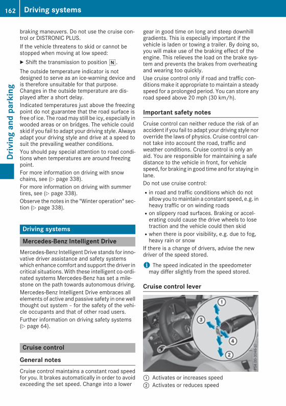
braking maneuvers. Do not use the cruise con-trol or DISTRONIC PLUS.If the vehicle threatens to skid or cannot bestopped when moving at low speed:X Shift the transmission to positioni.The outside temperature indicator is notdesigned to serve as an ice-warning device andis therefore unsuitable for that purpose.Changes in the outside temperature are dis-played after a short delay.Indicated temperatures just above the freezingpoint do not guarantee that the road surface isfree of ice. The roadmay still be icy, especially inwooded areas or on bridges. The vehicle couldskid if you fail to adapt your driving style. Alwaysadapt your driving style and drive at a speed tosuit the prevailing weather conditions.You should pay special attention to road condi-tions when temperatures are around freezingpoint.For more information on driving with snowchains, see (Y page 338).For more information on driving with summertires, see (Y page 338).Observe the notes in the "Winter operation" sec-tion (Y page 338).
Driving systems
Mercedes-Benz Intelligent DriveMercedes-Benz Intelligent Drive stands for inno-vative driver assistance and safety systemswhich enhance comfort and support the driver incritical situations. With these intelligent co-ordi-nated systems Mercedes-Benz has set a mile-stone on the path towards autonomous driving.Mercedes-Benz Intelligent Drive embraces allelements of active and passive safety in onewellthought out system – for the safety of the vehi-cle occupants and that of other road users.Further information on driving safety systems(Y page 64).
Cruise control
General notesCruise control maintains a constant road speedfor you. It brakes automatically in order to avoidexceeding the set speed. Change into a lower
gear in good time on long and steep downhillgradients. This is especially important if thevehicle is laden or towing a trailer. By doing so,you will make use of the braking effect of theengine. This relieves the load on the brake sys-tem and prevents the brakes from overheatingand wearing too quickly.Use cruise control only if road and traffic con-ditions make it appropriate to maintain a steadyspeed for a prolonged period. You can store anyroad speed above 20 mph (30 km/h).
Important safety notesCruise control can neither reduce the risk of anaccident if you fail to adapt your driving style noroverride the laws of physics. Cruise control can-not take into account the road, traffic andweather conditions. Cruise control is only anaid. You are responsible for maintaining a safedistance to the vehicle in front, for vehiclespeed, for braking in good time and for staying inlane.Do not use cruise control:Rin road and traffic conditions which do notallow you tomaintain a constant speed, e.g. inheavy traffic or on winding roadsRon slippery road surfaces. Braking or accel-erating could cause the drive wheels to losetraction and the vehicle could then skidRwhen there is poor visibility, e.g. due to fog,heavy rain or snow
If there is a change of drivers, advise the newdriver of the speed stored.
i The speed indicated in the speedometermay differ slightly from the speed stored.
Cruise control lever
: Activates or increases speed; Activates or reduces speed
162 Driving systemsDrivingandparking

= Deactivates cruise control? Activates at the current speed/last stored
speedWhen you activate cruise control, the storedspeed is shown in the multifunction display forfive seconds. Theé symbol appears on themultifunction display.Speedometer with segments: when cruisecontrol is activated, the segments from thestored speed to the end of the scale light up.
Storing and maintaining the currentspeedYou can store the current speed if you are driv-ing faster than 20 mph (30 km/h).X Accelerate the vehicle to the desired speed.X Briefly press the cruise control lever up: ordown;.
X Remove your foot from the accelerator pedal.Cruise control is activated. The vehicle auto-matically maintains the stored speed.
i Cruise control may be unable to maintainthe stored speed on uphill gradients. Thestored speed is resumed when the gradientevens out. Cruise control maintains thestored speed on downhill gradients by auto-matically applying the brakes.
Storing the current speed or calling upthe last stored speed
G WARNINGIf you call up the stored speed and it is lowerthan the current speed, the vehicle deceler-ates. If you do not know the stored speed, thevehicle could decelerate unexpectedly. Thereis a risk of an accident.Pay attention to the road and traffic condi-tions before calling up the stored speed. If youdo not know the stored speed, store thedesired speed again.
X Briefly pull the cruise control lever towardsyou?.
X Remove your foot from the accelerator pedal.The first time cruise control is activated, itstores the current speed or regulates thespeed of the vehicle to the previously storedspeed.
Setting a speedKeep in mind that it may take a brief momentuntil the vehicle has accelerated or braked tothe speed set.X Press the cruise control lever up: for ahigher speed or down; for a lower speed.
X To adjust the set speed in 1 mph incre-ments (1 km/h increments): briefly pressthe cruise control lever up: or down; tothe pressure point.Every time the cruise control lever is pressedup: or down; the last speed stored isincreased or reduced.
X To adjust the set speed in 5 mph incre-ments (10km/h increments): briefly pressthe cruise control lever up: or down;beyond the pressure point.Every time the cruise control lever is pressedup: or down; the last speed stored isincreased or reduced.i Cruise control is not deactivated if youdepress the accelerator pedal. If you acceler-ate to overtake, cruise control adjusts thevehicle's speed to the last speed stored afteryou have finished overtaking.
Deactivating cruise controlThere are several ways to deactivate cruise con-trol:X Briefly press the cruise control lever forward=.
orX Brake.Cruise control is automatically deactivated if:Ryou engage the electric parking brakeRyou are driving at less than 20mph (30 km/h)RESP® intervenes or you deactivate ESP®Ryou shift the transmission to positioniwhile driving
If cruise control is deactivated, a warning tonesounds. You will see the Cruise Control Offmessage in themultifunction display for approx-imately five seconds. The message on the mul-tifunction display disappears and the segmentson the speedometer go out.
i When you switch off the engine, the lastspeed stored is cleared.
Driving systems 163
Drivingandparking
Z

DISTRONIC PLUS
General notesDISTRONIC PLUS regulates the speed and auto-matically helps you maintain the distance fromthe vehicle detected in front. Vehicles are detec-ted with the aid of the radar sensor system.DISTRONIC PLUS brakes automatically so thatthe set speed is not exceeded.Change into a lower gear in good time on longand steep downhill gradients. This is especiallyimportant if the vehicle is laden. By doing so, youwill make use of the braking effect of the engine.This relieves the load on the brake system andprevents the brakes from overheating and wear-ing too quickly.If DISTRONIC PLUS detects that there is a risk ofa collision, you will be warned visually andacoustically. DISTRONIC PLUS cannot prevent acollision without your intervention. An intermit-tent warning tone will then sound and the dis-tance warning lamp will light up in the instru-ment cluster. Brake immediately in order toincrease the distance to the vehicle in front ortake evasive action provided it is safe to do so.DISTRONIC PLUS operates in the speed rangebetween 0 mph (0 km/h) and 120 mph(200 km/h).Do not use DISTRONIC PLUS while driving onroads with steep gradients.As DISTRONIC PLUS transmits radar waves, itcan resemble the radar detectors of the respon-sible authorities. You can refer to the relevantchapter in the Operator's Manual if questionsare asked about this.
i USA only: This device has been approved bythe FCC as a "Vehicular Radar System". Theradar sensor is intended for use in an auto-motive radar system only. Removal, tamper-ing, or altering of the device will void any war-ranties, and is not permitted by the FCC. Donot tamper with, alter, or use in any non-approved way.Any unauthorized modification to this devicecould void the user's authority to operate theequipment.
i Canada only: This device complies withRSS-210 of Industry Canada. Operation issubject to the following two conditions:1. This device may not cause interference,and
2. This device must accept any interferencereceived, including interference that maycause undesired operation of the device.Removal, tampering, or altering of the devicewill void any warranties, and is not permitted.Do not tamper with, alter, or use in any non-approved way.Any unauthorized modification to this devicecould void the user's authority to operate theequipment.
Important safety notes
G WARNINGDISTRONIC PLUS does not react to:Rpeople or animalsRstationary obstacles on the road, e.g. stop-ped or parked vehiclesRoncoming and crossing trafficAs a result, DISTRONIC PLUSmay neither givewarnings nor intervene in such situations.There is a risk of an accident.Always pay careful attention to the traffic sit-uation and be ready to brake.
G WARNINGDISTRONIC PLUS cannot always clearly iden-tify other road users and complex traffic sit-uations.In such cases, DISTRONIC PLUS may:Rgive an unnecessary warning and thenbrake the vehicleRneither give a warning nor interveneRaccelerate or brake unexpectedlyThere is a risk of an accident.Continue to drive carefully and be ready tobrake, in particular when warned to do so byDISTRONIC PLUS.
G WARNINGDISTRONIC PLUS brakes your vehicle with upto 50% of themaximumpossible deceleration.If this braking force is insufficient, DISTRONICPLUS warns you visually and audibly. There isa risk of an accident.
164 Driving systemsDrivingandparking

In such cases, apply the brakes yourself andtry to take evasive action.
! When DISTRONIC PLUS or the HOLD func-tion is activated, the vehicle brakes automat-ically in certain situations.To avoid damage to the vehicle, deactivateDISTRONIC PLUS and the HOLD function inthe following or similar situations:Rwhen towing the vehicleRin the car wash
DISTRONIC PLUS can neither reduce the risk ofan accident if you fail to adapt your driving stylenor override the laws of physics. DISTRONICPLUS cannot take account of road, weather andtraffic conditions. DISTRONIC PLUS is only anaid. You are responsible for maintaining a safedistance to the vehicle in front, for vehiclespeed, for braking in good time and for staying inlane.Do not use DISTRONIC PLUS:Rin road and traffic conditions which do notallow you tomaintain a constant speed, e.g. inheavy traffic or on winding roadsRon slippery road surfaces. Braking or accel-erating could cause the drive wheels to losetraction and the vehicle could then skidRin poor visibility, e.g. due to fog, heavy rain orsnow
DISTRONIC PLUS may not detect narrow vehi-cles driving in front, e.g. motorcycles, or vehi-cles driving on a different line.In particular, the detection of obstacles can beimpaired if:Rthere is dirt on the sensors or anything elsecovering the sensorsRthere is snow or heavy rainRthere is interference by other radar sourcesRthere are strong radar reflections, for exam-ple in parking garages
If DISTRONIC PLUS no longer detects a vehiclein front, DISTRONIC PLUS may unexpectedlyaccelerate the vehicle to the stored speed.
This speed may:Rbe too high if you are driving in a filter lane oran exit laneRbe so high in the right lane that you pass vehi-cles driving on the left (left-hand drive coun-tries)Rbe so high in the left lane that you pass vehi-cles driving on the right (in countries wherethey drive on the left)
If there is a change of drivers, advise the newdriver of the speed stored.
Cruise control lever
: Activates or increases speed; Activates or reduces speed= Deactivates DISTRONIC PLUS? Activates at the current speed/last stored
speedA Sets a specified minimum distanceWhen you activate DISTRONIC PLUS, the storedspeed appears in the multifunction display forfive seconds.Speedometer with segments: whenDISTRONIC PLUS is activated, the segmentsfrom the stored speed to the end of the scale orto a permanently set speed limit light up.
Activating DISTRONIC PLUS
Activation conditionsTo activate DISTRONIC PLUS, the following con-ditions must be fulfilled:Rthe engine must be started. It may take up totwo minutes of driving before DISTRONICPLUS is ready for use.Rthe electric parking brake must be released.RESP® must be activated, but not interveningat present.
Driving systems 165
Drivingandparking
Z

RActive Parking Assist must not be activated.Rthe transmission must be in positionh.Rthe driver's door must be closed when youshift the transmission from positionj tohor your seat belt must be fastened.Rthe front-passenger door and rear doorsmustbe closed.Rthe vehicle must not slide.
ActivatingX Briefly pull the cruise control lever towardsyou? or push it up: or down;.DISTRONIC PLUS is activated.
X Remove your foot from the accelerator pedal.The vehicle adapts its speed to that of thevehicle in front, but only up to the desiredstored speed.If you do not fully release the acceleratorpedal, the DISTRONIC PLUS Suspendedmes-sage appears on the multifunction display.The set distance to a slower-moving vehicle infront will then not be maintained. You will bedriving at the speed you determine by theposition of the accelerator pedal.
You can also activate DISTRONIC PLUS whenstationary. The lowest speed that can be set is20 mph (30 km/h).X Briefly pull the cruise control lever towardsyou? or push it up: or down;.DISTRONIC PLUS is activated.
Activating at the current speed/laststored speedG WARNINGIf you call up the stored speed and it differsfrom the current speed, the vehicle acceler-ates or decelerates. If you do not know thestored speed, the vehicle could accelerate orbrake unexpectedly. There is a risk of an acci-dent.Pay attention to the road and traffic condi-tions before calling up the stored speed. If youdo not know the stored speed, store thedesired speed again.
X Briefly pull the cruise control lever towardsyou?.
X Remove your foot from the accelerator pedal.DISTRONIC PLUS is activated. The first time itis activated, the current speed is stored. Oth-
erwise, it sets the vehicle speed to the previ-ously stored value.
Driving with DISTRONIC PLUS
Pulling away and drivingX If you want to pull away with DISTRONICPLUS: remove your foot from the brake pedal.
X Briefly pull the cruise control lever towardsyou?.
orX Accelerate briefly.The vehicle pulls away and adapts its speed tothat of the vehicle in front. If no vehicle isdetected in front, your vehicle accelerates tothe stored speed.
The vehicle can also pull away when it is facingan unidentified obstacle or is driving on a differ-ent line from another vehicle. The vehicle thenbrakes automatically.If DISTRONIC PLUS does not detect a vehicle infront, the system operates like a cruise control.If DISTRONIC PLUS detects that the vehicle infront is driving slower, your vehicle brakes. Inthis way, the specified minimum distance youhave selected is maintained.If DISTRONIC PLUS detects that the vehicle infront is driving faster, your vehicle acceleratesto the stored speed.
Selects the drive programDISTRONIC PLUS supports a sporty driving stylewhen you have selected the S or S+ driving pro-gram (Y page 144). Acceleration behind thevehicle in front or to the set speed is then notice-ablymore dynamic. If you have selected theC orE driving program, the vehicle accelerates moregently. This setting is recommended in stop-and-start traffic.
Changing lanesDISTRONIC PLUS aids you when switching tothe overtaking lane, if:Ryou are driving faster than 45 mph (70 km/h)Ryou switch on the appropriate turn signalRDISTRONIC PLUS does not currently detect adanger of a collision
If these conditions are fulfilled, your vehicle isaccelerated. Acceleration will be interrupted ifchanging lanes takes too long or if the distance
166 Driving systemsDrivingandparking
between your vehicle and the vehicle in frontbecomes too small.When you change lanes, DISTRONIC PLUSmon-itors the left lane (on left-hand-drive vehicles) orthe right lane (on right-hand-drive vehicles).
StoppingG WARNINGWhen leaving the vehicle, even if it is brakedonly by DISTRONIC PLUS, it could roll away if:Rthere is a malfunction in the system or inthe voltage supply.RDISTRONIC PLUS has been deactivatedwith the cruise control lever, e.g. by a vehi-cle occupant or from outside the vehicle.Rthe electrical system in the engine com-partment, the battery or the fuses havebeen tampered with.Rthe battery is disconnected.Rthe accelerator pedal has been depressed,e.g. by a vehicle occupant.
There is a risk of an accident.If you wish to exit the vehicle, always turn offDISTRONIC PLUS and secure the vehicleagainst rolling away.
For further information on deactivatingDISTRONIC PLUS (Y page 169).If DISTRONIC PLUS detects that the vehicle infront has stopped, it will cause your vehicle tobrake and come to a halt.Once your vehicle is stationary, it remains sta-tionary and you do not need to depress thebrake.After a time, the electric parking brake securesthe vehicle and relieves the service brake.Depending on the specified minimum distance,your vehicle will come to a standstill at a suffi-cient distance behind the vehicle in front. Thespecified minimum distance is set using thecontrol on the cruise control lever.
When DISTRONIC PLUS is activated, the trans-mission is shifted automatically to positionj,if:Rthe driver's seat belt is not fastened and thedriver's door is open.Rthe engine is switched off, unless it is auto-matically switched off by the ECO start/stopfunction.
The electric parking brake secures the vehicleautomatically if DISTRONIC PLUS is activatedwhen the vehicle is stationary and:Ra system malfunction occurs.Rthe power supply is insufficient.If a malfunction occurs, the transmission mayalso be shifted to positionj automatically.
Setting a speedX Push the cruise control lever up: for ahigher speed or down; for a lower speed.
X To adjust the set speed in 1 mph incre-ments (1 km/h increments): briefly pushthe cruise control lever up: or down; tothe pressure point.Every time the cruise control lever is pressedup: or down; the last speed stored isincreased or reduced.
X To adjust the set speed in 5 mph incre-ments (10 km/h increments): briefly pushthe cruise control lever up: or down;beyond the pressure point.Every time the cruise control lever is pressedup: or down;, the last speed stored isincreased or reduced.
i If you accelerate to overtake, DISTRONICPLUS adjusts the vehicle's speed back to thelast speed stored after you have finished over-taking.
Setting a specified minimum distanceYou can set the specified minimum distance forDISTRONIC PLUS by varying the time spanbetween one and two seconds. With this func-tion, you can set the minimum distance thatDISTRONIC PLUS maintains to the vehicle infront, depending on the driving speed. You cansee this distance in the multifunction display(Y page 168).Make sure that you maintain the minimum dis-tance to the vehicle in front as required by law.
Driving systems 167
Drivingandparking
Z

Adjust the distance to the vehicle in front if nec-essary.
X To increase: turn control; in direction=.DISTRONIC PLUS then maintains a greaterdistance between your vehicle and the vehiclein front.
X To decrease: turn control; in direction:.DISTRONIC PLUS then maintains a shorterdistance between your vehicle and the vehiclein front.
DISTRONIC PLUS displays in the instru-ment cluster
Displays in the speedometer
If DISTRONIC PLUS detects a vehicle in front,the segments between the speed of the vehiclein front: and stored speed; light up.Vehicles with the Driving Assistance Pluspackage: the segments likewise light up if avehicle in front is detected in the fast lane.For design reasons, the speed displayed in thespeedometer may differ slightly from the speedset for DISTRONIC PLUS.
Displays in the assistance graphic
Display when DISTRONIC PLUS is deac-tivated
: Vehicle in front, if detected; Distance indicator, current distance to the
vehicle in front= Specified minimum distance to the vehicle
in front; adjustable? Own vehicle
Display when DISTRONIC PLUS is activa-ted
: DISTRONIC PLUS active (text only appearswhen the cruise control lever is actuated)
; Vehicle in front, if detected= Specified minimum distance to the vehicle
in front; adjustable? Own vehicleX To call up the assistance graphic:select theAssistance Graphic function using the on-board computer (Y page 219).Themultifunction display will show the storedspeed for about five seconds when you acti-vate DISTRONIC PLUS.
168 Driving systemsDrivingandparking
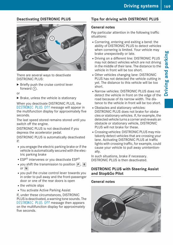
Deactivating DISTRONIC PLUS
There are several ways to deactivateDISTRONIC PLUS:X Briefly push the cruise control leverforward:.
orX Brake, unless the vehicle is stationaryWhen you deactivate DISTRONIC PLUS, theDISTRONIC PLUS Off message will appear inthe multifunction display for approximately fiveseconds.The last speed stored remains stored until youswitch off the engine.DISTRONIC PLUS is not deactivated if youdepress the accelerator pedal.DISTRONIC PLUS is automatically deactivatedif:Ryou engage the electric parking brake or if thevehicle is automatically securedwith the elec-tric parking brakeRESP® intervenes or you deactivate ESP®Ryou shift the transmission to positionj,koriRyou pull the cruise control lever towards youin order to pull away and the front-passengerdoor or one of the rear doors is openRthe vehicle slipsRYou activate Active Parking AssistIf, under these circumstances, DISTRONICPLUS is deactivated, awarning tone sounds. TheDISTRONIC PLUS Off message then appearson the multifunction display for approximatelyfive seconds.
Tips for driving with DISTRONIC PLUS
General notesPay particular attention in the following trafficsituations:RCornering, entering and exiting a bend: theability of DISTRONIC PLUS to detect vehicleswhen cornering is limited. Your vehicle maybrake unexpectedly or late.RDriving on a different line: DISTRONIC PLUSmay not detect vehicles which are not drivingin the middle of their lane. The distance to thevehicle in front will be too short.ROther vehicles changing lane: DISTRONICPLUS has not detected the vehicle cutting inyet. The distance to this vehicle will be tooshort.RNarrow vehicles: DISTRONIC PLUS does notdetect the vehicle in front on the edge of theroad because of its narrow width. The dis-tance to the vehicle in front will be too short.RObstacles and stationary vehicles:DISTRONIC PLUS does not brake for obsta-cles or stationary vehicles. If, for example, thedetected vehicle turns a corner and reveals anobstacle or stationary vehicle, DISTRONICPLUS will not brake for these.RCrossing vehicles: DISTRONIC PLUSmaymis-takenly detect vehicles that are crossing yourlane. Activating DISTRONIC PLUS at trafficlights with crossing traffic, for example, couldcause your vehicle to pull away unintention-ally.
In such situations, brake if necessary.DISTRONIC PLUS is then deactivated.
DISTRONIC PLUS with Steering Assistand Stop&Go Pilot
General notes
Driving systems 169
Drivingandparking
Z

DISTRONIC PLUS with Steering Assist andStop&Go Pilot helps you keep the vehicle in thecenter of the lane by means of moderate steer-ing interventions in a speed range from0–125 mph (0–200 km/h).It monitors the area in front of your vehicle bymeans of multifunction camera:, at the top ofthe windshield.In a speed range from 0 - 37 mph (0 - 60 km/h),Stop&Go Pilot focuses on the vehicle in front,taking into account lane markings, e.g. whenyou are following vehicles in a traffic jam.At speeds of more than 37 mph (60 km/h),Steering Assist focuses on clear lane markings(left and right), only focusing on the vehicle infront if clear lane markings are not present.If these conditions are not present, SteeringAssist and Stop&Go Pilot cannot provide assis-tance.DISTRONIC PLUSmust be active in order for thefunction to be available.
Important safety notesIf you fail to adapt your driving style, DISTRONICPLUS with Steering Assist and Stop&Go Pilotcan neither reduce the risk of an accident noroverride the laws of physics. It cannot takeaccount of road, weather and traffic conditions.DISTRONIC PLUS with Steering Assist andStop&Go Pilot is only an aid. You are responsiblefor maintaining a safe distance to the vehicle infront, for vehicle speed, for braking in good timeand for staying in lane.DISTRONIC PLUS with Steering Assist andStop&Go Pilot does not detect road and trafficconditions and does not detect all road users. Ifyou are following a vehicle which is drivingtowards the edge of the road, your vehicle couldcome into contact with the curb or other roadboundaries. Be particularly aware of other roadusers, e.g. cyclists, that are directly next to yourvehicle.Obstacles such as traffic pylons on the lane orprojecting out into the lane are not detected.An inappropriate steering intervention, e.g. afterintentionally driving over a lane marking, can becorrected at any time if you steer slightly in theopposite direction.DISTRONIC PLUS with Steering Assist andStop&Go Pilot cannot continuously keep yourvehicle in lane. In some cases, steering inter-vention is not sufficient to bring the vehicle backto the lane. In such cases, you must steer the
vehicle yourself to ensure that it does not leavethe lane.The systemmay be impaired ormay not functionif:Rthere is poor visibility, e.g. due to insufficientillumination of the road, or due to snow, rain,fog or sprayRthere is glare, e.g. from oncoming traffic, thesun or reflection from other vehicles (e.g. ifthe road surface is wet)Rthewindshield is dirty, fogged up, damaged orcovered, for instance by a sticker, in the vicin-ity of the cameraRthere are no, several or unclear lanemarkingsfor a lane, e.g. in areas with road constructionworkRthe lanemarkings are worn away, dark or cov-ered up, e.g. by dirt or snowRthe distance to the vehicle in front is too smalland the lane markings thus cannot be detec-tedRthe lane markings change quickly, e.g. lanesbranch off, cross one another or mergeRthe road is narrow and windingRthere are highly variable shade conditions onthe roadway
The system is switched to passive and no longerassists you by performing steering interventionsif:Ryou actively change laneRyou switch on the turn signalRyou take your hands off the steering wheel ordo not steer for a prolonged period of time
Steering Assist and Stop&Go Pilot are activatedagain automatically after a lane change is com-pleted.Steering Assist and Stop&Go Pilot do not pro-vide any support:Ron very sharp cornersRwhen a loss of tire pressure or a defective tirehas been detected and displayed
Pay attention also to the important safety notesfor DISTRONIC PLUS (Y page 164).The steering interventions are carried out with alimited steering moment. The system requiresthe driver to keep his hands on the steeringwheel and to steer himself.If you do not steer yourself or if you take yourhands off the steering wheel for a prolongedperiod of time, the systemwill first alert youwith
170 Driving systemsDrivingandparking

a visual warning. A steering wheel symbolappears in the multifunction display. If you havestill not started to steer and have not taken holdof the steering wheel after five seconds at thelatest, a warning tone also sounds to remind youto take control of the vehicle. Steering Assistand Stop&Go Pilot are switched to passive.DISTRONIC PLUS remains active.
Activating Steering Assist and Stop&GoPilot
X Press button;.Indicator lamp: lights up. The DTR+:Steering Assist. On message appears inthe multifunction display. Steering Assist andStop&Go Pilot are activated.
Information in the multifunction display
If Steering Assist and Stop&Go Pilot are activa-ted but is not ready for a steering intervention,steering wheel symbol: appears in gray. If thesystem provides you with support by means ofsteering interventions, symbol: is shown ingreen.
Deactivating Steering Assist and Stop&GoPilotX Press button;.Indicator lamp: goes out. The DTR+:Steering Assist. Offmessage appears inthe multifunction display. Steering Assist andStop&Go Pilot are deactivated.
When DISTRONIC PLUS is deactivated or notavailable, Steering Assist and Stop&Go Pilot aredeactivated automatically.
HOLD function
General notesThe HOLD function can assist the driver in thefollowing situations:Rwhen pulling away, especially on steep slopesRwhen maneuvering on steep slopesRwhen waiting in trafficThe vehicle is kept stationary without the driverhaving to depress the brake pedal.The braking effect is canceled and the HOLDfunction deactivated when you depress theaccelerator pedal to pull away.
Important safety notes
G WARNINGWhen leaving the vehicle, it can still roll awaydespite being braked by the HOLD function if:Rthere is a malfunction in the system or inthe voltage supply.Rthe HOLD function has been deactivated bypressing the accelerator pedal or the brakepedal, e.g. by a vehicle occupant.Rthe electrical system in the engine com-partment, the battery or the fuses havebeen tampered with.Rthe battery is disconnectedThere is a risk of an accident.If you wish to exit the vehicle, always turn offthe HOLD function and secure the vehicleagainst rolling away.
! When DISTRONIC PLUS or the HOLD func-tion is activated, the vehicle brakes automat-ically in certain situations.
Driving systems 171
Drivingandparking
Z

To avoid damage to the vehicle, deactivateDISTRONIC PLUS and the HOLD function inthe following or similar situations:Rwhen towing the vehicleRin the car wash
Deactivating the HOLD function (Y page 172).
Activation conditionsYou can activate the HOLD function if all of thefollowing conditions are fulfilled:Rthe vehicle is stationary.Rthe engine is running or if it has been auto-matically switched off by the ECO start/stopfunction.Rthe driver's door is closed or your seat belt isfastened.Rthe electric parking brake is released.Rthe transmission is in positionh,k ori.RDISTRONIC PLUS is deactivated.
Activating the HOLD function
X Make sure that the activation conditions aremet.
X Depress the brake pedal.X Quickly depress the brake pedal furtheruntil: appears in the multifunction display.The HOLD function is activated. You canrelease the brake pedal.
If depressing the brake pedal the first time doesnot activate the HOLD function, wait briefly andthen try again.
Deactivating the HOLD functionThe HOLD function is deactivated automaticallyif:Ryou depress the accelerator and the trans-mission is in positionh orkRthe transmission is in positionjRyou depress the brake pedal again with a cer-tain amount of pressure until displayëdisappears from the multifunction displayRyou secure the vehicle using the electric park-ing brakeRyou activate DISTRONIC PLUSAfter a time, the electric parking brake securesthe vehicle and relieves the service brake.When the HOLD function is activated, the trans-mission is shifted automatically to positionjif:Rthe driver's seat belt is not fastened and thedriver's door is open.Rthe engine is switched off, unless it is auto-matically switched off by the ECO start/stopfunction.
The electric parking brake secures the vehicleautomatically if the HOLD function is activatedwhen the vehicle is stationary and:Ra system malfunction occurs.Rthe power supply is insufficient.If a malfunction occurs, the transmission mayalso be shifted to positionj automatically.
AIR BODY CONTROL
General notesAIRBODYCONTROL is an air suspension systemwith variable damping for improved driving com-fort. All-round level control ensures the bestpossible suspension and constant ground clear-ance, even with a laden vehicle. When you drivefast, the vehicle is lowered automatically toimprove driving safety and to reduce fuel con-sumption. There is also the option to manuallyadjust the vehicle level. AIR BODY CONTROLconsists of level setting, level control and theADS Adaptive Damping System.The vehicle level can be set using the DYNAMICSELECT switch (Y page 139) or the level button(Y page 173). The setting always correspondsto the last selected function.
172 Driving systemsDrivingandparking
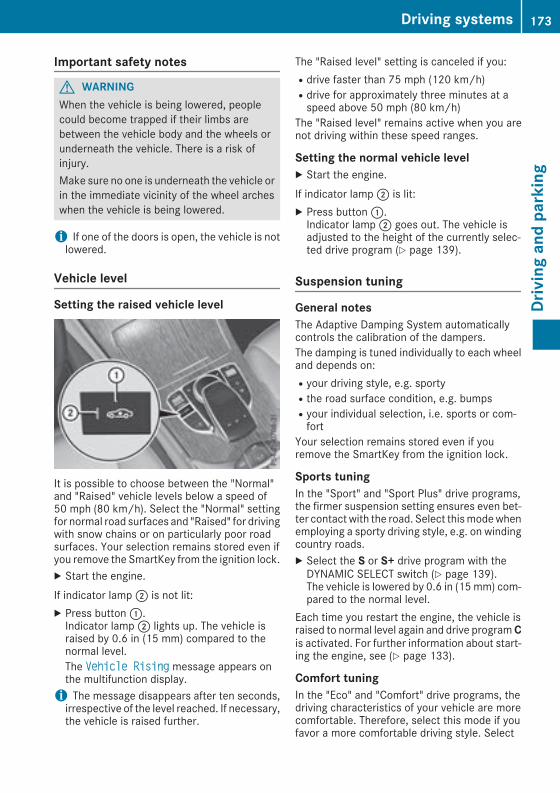
Important safety notes
G WARNINGWhen the vehicle is being lowered, peoplecould become trapped if their limbs arebetween the vehicle body and the wheels orunderneath the vehicle. There is a risk ofinjury.Make sure no one is underneath the vehicle orin the immediate vicinity of the wheel archeswhen the vehicle is being lowered.
i If one of the doors is open, the vehicle is notlowered.
Vehicle level
Setting the raised vehicle level
It is possible to choose between the "Normal"and "Raised" vehicle levels below a speed of50 mph (80 km/h). Select the "Normal" settingfor normal road surfaces and "Raised" for drivingwith snow chains or on particularly poor roadsurfaces. Your selection remains stored even ifyou remove the SmartKey from the ignition lock.X Start the engine.If indicator lamp; is not lit:X Press button:.Indicator lamp; lights up. The vehicle israised by 0.6 in (15 mm) compared to thenormal level.The Vehicle Rising message appears onthe multifunction display.i The message disappears after ten seconds,irrespective of the level reached. If necessary,the vehicle is raised further.
The "Raised level" setting is canceled if you:Rdrive faster than 75 mph (120 km/h)Rdrive for approximately three minutes at aspeed above 50 mph (80 km/h)
The "Raised level" remains active when you arenot driving within these speed ranges.
Setting the normal vehicle levelX Start the engine.If indicator lamp; is lit:X Press button:.Indicator lamp; goes out. The vehicle isadjusted to the height of the currently selec-ted drive program (Y page 139).
Suspension tuning
General notesThe Adaptive Damping System automaticallycontrols the calibration of the dampers.The damping is tuned individually to each wheeland depends on:Ryour driving style, e.g. sportyRthe road surface condition, e.g. bumpsRyour individual selection, i.e. sports or com-fort
Your selection remains stored even if youremove the SmartKey from the ignition lock.
Sports tuningIn the "Sport" and "Sport Plus" drive programs,the firmer suspension setting ensures even bet-ter contact with the road. Select thismodewhenemploying a sporty driving style, e.g. on windingcountry roads.X Select the S or S+ drive program with theDYNAMIC SELECT switch (Y page 139).The vehicle is lowered by 0.6 in (15mm) com-pared to the normal level.
Each time you restart the engine, the vehicle israised to normal level again and drive programCis activated. For further information about start-ing the engine, see (Y page 133).
Comfort tuningIn the "Eco" and "Comfort" drive programs, thedriving characteristics of your vehicle are morecomfortable. Therefore, select this mode if youfavor a more comfortable driving style. Select
Driving systems 173
Drivingandparking
Z
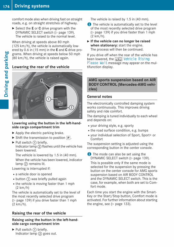
comfort mode also when driving fast on straightroads, e.g. on straight stretches of highway.X Select the E or C drive program with theDYNAMIC SELECT switch (Y page 139).The vehicle is raised to the normal level.
When driving at speeds above 80 mph(125 km/h), the vehicle is automatically low-ered by 0.6 in (15 mm) in the E and C drive pro-grams. When driving at speeds below 50 mph(80 km/h), the vehicle is raised again.
Lowering the rear of the vehicle
Lowering using the button in the left-hand-side cargo compartment trimX Apply the electric parking brake.X Shift the transmission to positionj.X Pull switch: briefly.Indicator lamp; flashes until the vehicle hasbeen lowered.The vehicle is lowered by 1.5 in (40 mm).When the vehicle has been lowered, indicatorlamp; remains lit.
Lowering is interrupted if:Ra vehicle door is openedRbutton: was briefly pulled againRthe vehicle is moving faster than 1 mph(2 km/h)
The vehicle is automatically set to the level ofthe most recently selected drive program(Y page 139) if you drive faster than 1 mph(2 km/h).
Raising the rear of the vehicleRaising using the button in the left-hand-side cargo compartment trimX Pull switch: briefly.Indicator lamp; goes out.
The vehicle is raised by 1.5 in (40 mm).i The vehicle is automatically set to the levelof the most recently selected drive program(Y page 139) if you drive faster than 1 mph(2 km/h).
X If the vehicle can no longer be raisedwhen stationary: start the engine.The process will then be continued.
If you drive off when the rear of the vehicle hasbeen lowered, theÁ Vehicle RisingPlease Waitmessage may appear on the mul-tifunction display.
AMG sports suspension based on AIRBODYCONTROL (Mercedes-AMG vehi-cles)
General notesThe electronically controlled damping systemworks continuously. This improves drivingsafety and ride comfort.The damping is tuned individually to each wheeland depends on:Ryour driving style, e.g. sportyRthe road surface condition, e.g. bumpsRyour individual selection of Sport, Sport+ orComfort
The suspension setting is adjusted using thecorresponding button in the center console.
i The mode can also be set using theDYNAMIC SELECT switch (Y page 139).This is possible only if the same mode isselected for the suspension by pressing thebutton on the center console for AMG sportssuspension based on AIR BODY CONTROLand the DYNAMIC SELECT switch. This is thecase, for example, when both are set to Com-fort mode.
Each time you start the engine with the Smart-Key or the Start/Stop button, Comfort mode isactivated. For further information about startingthe engine, see (Y page 133).
174 Driving systemsDrivingandparking

Sport mode
The firmer setting of the suspension tuning inSport mode ensures even better contact withthe road. Select this mode when employing asporty driving style, e.g. on winding countryroads.X Press button:.Indicator lamp= lights up. You have selectedSport mode.The AMG Suspension System SPORT mes-sage appears on the multifunction display.
Sport + modeThe very firm setting of the suspension setting inSport + mode ensures the best possible contactwith the road. Select this mode only when driv-ing on race circuits.If indicator lamps; and= are off:X Press button: twice.Indicator lamps; and= light up. You haveselected Sport + mode.The AMG Suspension System SPORT +mes-sage appears on the multifunction display.
If indicator lamp= lights up:X Press button: once.Second indicator lamp; lights up. You haveselected Sport + mode.The AMG Suspension System SPORT +mes-sage appears on the multifunction display.
Comfort modeIn Comfort mode, the driving characteristics ofyour vehicle are more comfortable. Select thismode if you favor a more comfortable drivingstyle, but also when driving fast on straightroads, e.g. highways.
X Press button: repeatedly until indicatorlamps; and= go out.You have selected Comfort mode.The AMG Suspension System COMFORTmes-sage appears on the multifunction display.
4MATIC (permanent four-wheel drive)4MATIC ensures permanent drive for all fourwheels. Together with ESP®, it improves thetraction of your vehicle whenever a drive wheelspins due to insufficient grip.If you fail to adapt your driving style or if you areinattentive, 4MATIC can neither reduce the riskof an accident nor override the laws of physics.4MATIC does not take into accountRthe road and weather conditionsRthe traffic situation4MATIC is only an aid. You are responsible forthe distance to the vehicle in front, for vehiclespeed, for braking in good time and for staying inyour lane.If a drive wheel spins due to insufficient grip:ROnly depress the accelerator pedal as far asnecessary when pulling away.RAccelerate less when driving.
! Never tow the vehicle with one axle raised.This may damage the transfer case. Damageof this sort is not covered by the Mercedes-Benz Limited Warranty. All wheels mustremain either on the ground or be fully raised.Observe the instructions for towing the vehi-cle with all wheels in full contact with theground.
i In wintry driving conditions, the maximumeffect of 4MATIC can only be achieved if youuse winter tires (M+S tires), with snow chainsif necessary.
PARKTRONIC
Important safety notesPARKTRONIC is an electronic parking aid withultrasonic sensors. It monitors the area aroundyour vehicle using six sensors in the frontbumper and six sensors in the rear bumper.PARKTRONIC indicates visually and audibly thedistance between your vehicle and an object.
Driving systems 175
Drivingandparking
Z

PARKTRONIC is only an aid. It is not a replace-ment for your attention to your immediate sur-roundings. You are always responsible for safemaneuvering, parking and exiting a parkingspace. Make sure that there are no persons,animals or objects in the maneuvering areawhile maneuvering and parking in/leaving park-ing spaces.
! When parking, pay particular attention toobjects above or below the sensors, such asflower pots or trailer drawbars. PARKTRONICdoes not detect such objects when they are inthe immediate vicinity of the vehicle. Youcould damage the vehicle or the objects.The sensors may not detect snow and otherobjects that absorb ultrasonic waves.Ultrasonic sources such as an automatic carwash, the compressed-air brakes on a truckor a pneumatic drill could cause PARKTRONICto malfunction.PARKTRONIC may not function correctly onuneven terrain.
! Remove the detachable ball coupling if thetrailer tow hitch is not required. PARKTRONICmeasures the minimum detection range to anobstacle from the bumper, not the ball cou-pling.
PARKTRONIC is activated automatically whenyou:Rswitch on the ignitionRshift the transmission to positionh,k ori
PARKTRONIC is deactivated at speeds above11 mph (18 km/h). It is reactivated at lowerspeeds.PARKTRONIC is deactivated for the rear areawhen you establish an electrical connectionbetween your vehicle and a trailer.
Range of the sensorsPARKTRONIC does not take objects into con-sideration that are:Rbelow the detection range, e.g. people, ani-mals or objects.Rabove the detection range, for example over-hanging loads, truck overhangs or loadingramps.
: Sensors in the front bumper, left-hand side(example)
: Approx. 24 in (approx. 60 cm) (corners); Approx. 32 in (approx. 80 cm) (corners)= Approx. 48 in (approx. 120 cm) (center)? Approx. 40 in (approx. 100 cm) (center)The sensors must be free from dirt, ice or slush.They can otherwise not function correctly. Cleanthe sensors regularly, taking care not to scratchor damage them (Y page 315).Minimum distance
Center Approx. 8 in (approx. 20 cm)
Corners Approx. 6 in (approx. 15 cm)
176 Driving systemsDrivingandparking

If there is an obstacle within this range, the rel-evant warning displays light up and a warningtone sounds. If the distance falls below the min-imum, the distance may no longer be shown.
Warning displays
: Segments on the left-hand side of the vehi-cle
; Segments on the right-hand side of the vehi-cle
= Segments showing operational readinessThe warning displays show the distancebetween the sensors and the obstacle. Thewarning display for the front area is in the instru-ment cluster. The warning display for the reararea is located on the headliner in the rear com-partment.The warning display for each side of the vehicleis divided into five yellow and two red segments.PARKTRONIC is operational if operational read-iness indicator= lights up.The selected transmission position and thedirection in which the vehicle is rolling deter-mine which warning display is active when theengine is running.
Transmission posi-tion
Warning display
h Front area activated
k,i or the vehicleis rolling back
Rear and front areasactivated
j No areas activated
One or more segments light up as the vehicleapproaches an obstacle, depending on the vehi-cle's distance from the obstacle:RFrom the sixth segment, youwill hear an inter-mittent warning tone for approximately twoseconds.RFrom the seventh segment, you will hear awarning tone for approximately two seconds.This indicates that you have now reached theminimum distance.
Deactivating/activating PARKTRONIC
d Switch on the dashboarde Switch in the center console: Deactivates/activates PARKTRONIC; Indicator lampIf indicator lamp; lights up, PARKTRONIC isdeactivated. Active Parking Assist is then alsodeactivated.
i PARKTRONIC is automatically activatedwhen you turn the SmartKey to position2 inthe ignition lock.
Driving systems 177
Drivingandparking
Z
Problems with PARKTRONIC
Problem Possible causes/consequences andM Solutions
Only the red segments inthe PARKTRONIC warn-ing displays are lit. Youalso hear a warning tonefor approximately twoseconds.PARKTRONIC is thendeactivated and the indi-cator lamp on thePARKTRONIC buttonlights up.
PARKTRONIC has malfunctioned and has switched off.X If problems persist, have PARKTRONIC checked at a qualified spe-cialist workshop.
Only the red segments inthe PARKTRONIC warn-ing displays are lit.PARKTRONIC is thendeactivated.
The PARKTRONIC sensors are dirty or there is interference.X Clean the PARKTRONIC sensors (Y page 315).X Switch the ignition back on.
The problem may be caused by an external source of radio or ultra-sound waves.X See if PARKTRONIC functions in a different location.
Active Parking Assist
General notesActive Parking Assist is an electronic parking aidwith ultrasound. It measures the road on bothsides of the vehicle. A parking symbol indicatesa suitable parking space. Active steering inter-vention and brake application can assist youduring parking and when exiting a parkingspace. You may also use PARKTRONIC(Y page 175).
Important safety notesActive Parking Assist is merely an aid. It is not areplacement for your attention to your immedi-ate surroundings. You are always responsiblefor safe maneuvering, parking and exiting aparking space. Make sure that no persons, ani-mals or objects are in the maneuvering range.When PARKTRONIC is switched off, Active Park-ing Assist is also unavailable.For vehicles with a trailer tow hitch installed, theminimum length for parking spaces is slightlylonger.If you have attached a trailer to your vehicle, youshould not use Active Parking Assist. Once theelectrical connection is established between
your vehicle and the trailer, Active ParkingAssist is no longer available. PARKTRONIC isdeactivated for the rear area.
G WARNINGWhile parking or pulling out of a parkingspace, the vehicle swings out and can driveonto areas of the oncoming lane. This couldresult in a collision with another road user.There is a risk of an accident.Pay attention to other road users. Stop thevehicle if necessary or cancel the Active Park-ing Assist parking procedure.
! If unavoidable, you should drive over obsta-cles such as curbs slowly and not at a sharpangle. Otherwise, you may damage thewheels or tires.
Active Parking Assist may possibly indicateparking spaces which are not suitable for park-ing, for example:Rwhere parking or stopping is prohibitedRin front of driveways or entrances and exitsRon unsuitable surfaces
178 Driving systemsDrivingandparking

Parking tips:ROn narrow roads, drive as close to the parkingspace as possible.RParking spaces that are littered or overgrownmight be identified or measured incorrectly.RParking spaces that are partially occupied bytrailer drawbars might not be identified assuch or be measured incorrectly.RSnowfall or heavy rain may lead to a parkingspace being measured inaccurately.RPay attention to the PARKTRONIC(Y page 177) warning messages during theparking procedure.RYou can intervene in the steering procedureto correct it at any time. Active Parking Assistis then deactivated.RWhen transporting a load which protrudesfrom your vehicle, you should not use ActiveParking Assist.RNever use Active Parking Assist when snowchains are installed.RAlways pay attention to the specified tirepressure for your vehicle. This has a directinfluence on the parking characteristics of thevehicle.
Use Active Parking Assist for parking spaces:Rparallel or at right angles to the direction oftravelRon straight roads, not bendsRon the same level as the road, e.g. not on thepavement
Detecting parking spacesObjects located above the height range of ActiveParking Assist will not be detected when theparking space is measured. These are not takeninto account when the parking procedure is cal-culated, e.g. overhanging loads, truck over-hangs or loading ramps.
G WARNINGIf there are objects above the detection range:RActive Park Assist may steer too earlyRthe vehicle may not stop in front of theseobjects
You may cause a collision as a result. There isa risk of an accident.
If objects are located above the detectionrange, stop and deactivate Active ParkingAssist.
For further information on the detection range(Y page 176).Active Parking Assist does not assist you park-ing in spaces at right angles to the direction oftravel if:Rtwo parking spaces are located directly nextto one anotherRthe parking space is directly next to a lowobstacle such as a low curbRyou forward-parkActive Parking Assist does not assist you park-ing in spaces that are parallel or at right anglesto the direction of travel if:Rthe parking space is on a curbRthe system reads the parking space as beingblocked, for example by foliage or grass pav-ing blocksRthe area is too small for the vehicle to maneu-ver intoRthe parking space is bordered by an obstacle,e.g. a tree, a post or a trailer
: Detected parking space on the left; Parking symbol= Detected parking space on the rightActive Parking Assist is switched on automati-cally when driving forwards. The system isoperational at speeds of up to approximately22 mph (35 km/h). While in operation, the sys-tem independently locates and measures park-ing spaces on both sides of the vehicle.
Driving systems 179
Drivingandparking
Z
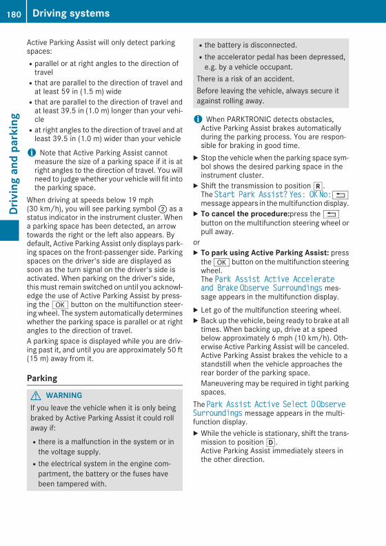
Active Parking Assist will only detect parkingspaces:Rparallel or at right angles to the direction oftravelRthat are parallel to the direction of travel andat least 59 in (1.5 m) wideRthat are parallel to the direction of travel andat least 39.5 in (1.0 m) longer than your vehi-cleRat right angles to the direction of travel and atleast 39.5 in (1.0 m) wider than your vehicle
i Note that Active Parking Assist cannotmeasure the size of a parking space if it is atright angles to the direction of travel. You willneed to judge whether your vehicle will fit intothe parking space.
When driving at speeds below 19 mph(30 km/h), you will see parking symbol; as astatus indicator in the instrument cluster. Whena parking space has been detected, an arrowtowards the right or the left also appears. Bydefault, Active Parking Assist only displays park-ing spaces on the front-passenger side. Parkingspaces on the driver's side are displayed assoon as the turn signal on the driver's side isactivated. When parking on the driver's side,this must remain switched on until you acknowl-edge the use of Active Parking Assist by press-ing thea button on the multifunction steer-ing wheel. The system automatically determineswhether the parking space is parallel or at rightangles to the direction of travel.A parking space is displayed while you are driv-ing past it, and until you are approximately 50 ft(15 m) away from it.
Parking
G WARNINGIf you leave the vehicle when it is only beingbraked by Active Parking Assist it could rollaway if:Rthere is a malfunction in the system or inthe voltage supply.Rthe electrical system in the engine com-partment, the battery or the fuses havebeen tampered with.
Rthe battery is disconnected.Rthe accelerator pedal has been depressed,e.g. by a vehicle occupant.
There is a risk of an accident.Before leaving the vehicle, always secure itagainst rolling away.
i When PARKTRONIC detects obstacles,Active Parking Assist brakes automaticallyduring the parking process. You are respon-sible for braking in good time.
X Stop the vehicle when the parking space sym-bol shows the desired parking space in theinstrument cluster.
X Shift the transmission to positionk.The Start Park Assist? Yes: OK No:%message appears in themultifunction display.
X To cancel the procedure:press the%button on the multifunction steering wheel orpull away.
orX To park using Active Parking Assist: pressthea button on themultifunction steeringwheel.The Park Assist Active Accelerateand Brake Observe Surroundings mes-sage appears in the multifunction display.
X Let go of the multifunction steering wheel.X Back up the vehicle, being ready to brake at alltimes. When backing up, drive at a speedbelow approximately 6 mph (10 km/h). Oth-erwise Active Parking Assist will be canceled.Active Parking Assist brakes the vehicle to astandstill when the vehicle approaches therear border of the parking space.Maneuvering may be required in tight parkingspaces.
The Park Assist Active Select D ObserveSurroundings message appears in the multi-function display.X While the vehicle is stationary, shift the trans-mission to positionh.Active Parking Assist immediately steers inthe other direction.
180 Driving systemsDrivingandparking

The Park Assist Active Accelerateand Brake Observe Surroundings mes-sage appears in the multifunction display.i You will achieve the best results by waitingfor the steering procedure to complete beforepulling away.
X Drive forwards and be ready to brake at alltimes.Active Parking Assist brakes the vehicle to astandstill when the vehicle approaches therear border of the parking space.Maneuvering may be required in tight parkingspaces.
The Park Assist Active Select R ObserveSurroundings message appears in the multi-function display.As soon as the parking procedure is complete,the Park Assist Switched Off messageappears and a warning tone sounds. The vehicleis now parked.The vehicle is kept stationary without the driverhaving to depress the brake pedal. The brakingeffect is canceled when you depress the accel-erator pedal.Active Parking Assist no longer supports youwith steering interventions and brake applica-tions. When Active Parking Assist is finished,you must steer and brake again yourself.PARKTRONIC is still available.Parking tips:RThe way your vehicle is positioned in the park-ing space after parking is dependent on vari-ous factors. These include the position andshape of the vehicles parked in front andbehind it and the conditions of the location. Itmay be the case that Active Parking Assistguides you too far into a parking space, or notfar enough into it. In some cases, it may alsolead you across or onto the curb. If necessary,you should cancel the parking procedure withActive Parking Assist.RYou can also preselect transmission positionh. The vehicle redirects and does not driveas far into the parking space. Should thetransmission change take place too early, theparking procedure will be canceled. A sensi-ble parking position can no longer be ach-ieved from this position.
Exiting a parking spaceIn order that Active Parking Assist can supportyou when you exit the parking space:Rthe border of the parking space must be highenough at the front and the rear. A curb is toosmall, for example.Rthe border of the parking space must not betoo wide. Your vehicle can be maneuveredinto a position at a maximum of 45° to thestarting position in the parking space.Ra maneuvering distance of at least 3.3 ft(1.0 m) must be available.
Active Parking Assist can only assist you withexiting a parking space if you have parked thevehicle parallel to the direction of travel usingActive Parking Assist.
i If PARKTRONIC detects obstacles, ActiveParking Assist brakes automaticallywhilst thevehicle exits the parking space. You areresponsible for braking in good time.
X Start the engine.X Release the electric parking brake.X Switch on the turn signal in the direction youare pulling away.
X Shift the transmission to positionh ork.The Start Park Assist? Yes: OK No:%message appears on the multifunction dis-play.
X To cancel the procedure:press the%button on the multifunction steering wheel orpull away.
orX To exit a parking space using Active Park-ing Assist: press thea button on themul-tifunction steering wheel.The Park Assist Active Accelerateand Brake Observe Surroundings mes-sage appears on the multifunction display.
X Let go of the multifunction steering wheel.X Pull away, being ready to brake at all times. Donot exceed a maximum speed of approx-imately 6mph (10 km/h) when exiting a park-ing space. Otherwise Active Parking Assistwill be canceled.
X Depending on the message or as required,shift the transmission to positionh ork.Active Parking Assist immediately steers inthe other direction. The Park AssistActive Accelerate and Brake Observe
Driving systems 181
Drivingandparking
Z

Surroundingsmessage appears on the mul-tifunction display.i You will achieve the best results by waitingfor the steering procedure to complete beforepulling away.If you back up after activation, the steeringwheel is moved to the straight-ahead posi-tion.
X Drive forward and back up as prompted by thePARKTRONIC warning displays, several timesif necessary.
Once you have exited the parking space com-pletely, the steering wheel is moved to thestraight-ahead position. You hear a tone and thePark Assist Switched Offmessage appearson the multifunction display. You will then haveto steer and merge into traffic on your own.PARKTRONIC is still available. You can take overthe steering before the vehicle has exited theparking space completely. This is useful if yourecognize that it is already possible to pull out ofthe parking space.
Canceling Active Parking AssistX Stop the movement of the multifunctionsteering wheel or steer yourself.Active Parking Assist will be canceled at once.The Park Assist Canceled messageappears in the multifunction display.
orX Press the PARKTRONIC button (Y page 177).PARKTRONIC is switched off and Active Park-ing Assist is immediately canceled. The ParkAssist Canceled message appears in themultifunction display.
Active Parking Assist is canceled automaticallyif:Rthe electric parking brake is engagedRtransmission positionj is selectedRparking using Active Parking Assist is no lon-ger possibleRyou are driving faster than 6 mph (10 km/h)Ra wheel spins, ESP® intervenes or fails. Insuch cases the÷warning lamp lights up inthe instrument cluster
A warning tone sounds. The parking symbol dis-appears and themultifunction display shows thePark Assist Canceled message.When Active Parking Assist is canceled, youmust steer and brake again yourself.
If a system malfunction occurs, the vehicle isbraked to a standstill. To drive on, depress theaccelerator again.
Rear view camera
General notes
Rear view camera: is an optical parking andmaneuvering aid. It shows the area behind thevehicle with guide lines in the multimedia sys-tem.The area behind the vehicle is displayed as amirror image, as in the rear view mirror.
i The text shown in the multimedia systemdepends on the language setting. The follow-ing are examples of rear view camera displaysin the multimedia system.
Important safety notesThe rear view camera is only an aid. It is not areplacement for your attention to your immedi-ate surroundings. You are always responsiblefor safe maneuvering and parking. Make surethat there are no persons, animals or objects inthe maneuvering area while maneuvering andparking in parking spaces.Under the following circumstances, the rearview camera will not function, or will function ina limited manner:Rif the tailgate is openRin heavy rain, snow or fogRat night or in very dark placesRif the camera is exposed to very bright lightRif the area is lit by fluorescent bulbs or LEDlighting (the display may flicker)
182 Driving systemsDrivingandparking

Rif there is a sudden change in temperature,e.g. when driving into a heated garage in win-terRif the camera lens is dirty or obstructedObserve the notes on cleaning(Y page 316)Rif the rear of your vehicle is damaged. In thiscase, have the camera position and settingchecked at a qualified specialist workshop
The field of vision and other functions of the rearview camera may be restricted due to additionalaccessories on the rear of the vehicle (e.g.license plate holder, rear bicycle rack).The rear view camera is protected from rain-drops and dust bymeans of a flap.When the rearview camera is activated, this flap opens.The flap closes again when:Ryou have finished the maneuvering processRyou switch off the engineRyou open the cargo compartmentObserve the notes on cleaning (Y page 316).For technical reasons, the flapmay remain openbriefly after the rear view camera has beendeactivated.
Activating/deactivating the rear viewcamera
X To activate: make sure that the Activa‐tion by R gear function is selected in themultimedia system (see theDigital Operator'sManual).
X Engage reverse gear.The rear view camera flap opens. The multi-media systemshows the area behind the vehi-cle with guide lines.The image from the rear view camera is avail-able throughout the maneuvering process.
X To switch the function mode for vehicleswith trailer tow hitch:using the controller,select symbol: for the "Reverse parking"function or symbol; for "Coupling up atrailer".The symbol of the selected function is high-lighted.
X To deactivate: shift the transmission to posi-tionj.
orX Drive forwards at a speed greater than 7 mph(12 km/h).
Multimedia displayThe rear view cameramay show a distorted viewof obstacles, show them incorrectly or not at all.The rear view camera does not show objects inthe following positions:Rvery close to the rear bumperRunder the rear bumperRin the area immediately above the tailgatehandle
! Objects not at ground level may appear tobe further away than they actually are, e.g.:Rthe bumper of a parked vehicleRthe drawbar of a trailerRthe ball coupling of a trailer tow hitchRthe rear section of an HGVRa slanted postUse the guidelines only for orientation.Approach objects no further than the bottom-most guideline.
Driving systems 183
Drivingandparking
Z

: Yellow guide line at a distance of approx-imately 13 ft (4.0 m) from the rear of thevehicle
; White guide lines without steering input,vehicle width including the exterior mirrors(static)
= Yellow guide lines for vehicle width includingthe exterior mirrors, for current steeringinput (dynamic)
? Yellow lanes marking the course the tireswill take at the current steering wheel angle(dynamic)
A Yellow guide line at a distance of approx-imately 3 ft (1.0 m) from the rear of the vehi-cle
B Vehicle center axle (marker assistance)C BumperD Red guide line at a distance of approximately
12 in (0.30 m) from the rear of the vehicleIf the transmission is shifted to positionk,guide lines appear in the camera image.The distance specifications only apply toobjects that are at ground level.
E Front warning displayF Rear warning displayG Additional vehicle icon: PARKTRONIC meas-
urement operational readiness indicatorVehicles with PARKTRONIC: whenPARKTRONIC is operational (Y page 177), vehi-cle symbolG appears in themultimedia systemdisplay. If the PARKTRONICwarning displays areactive or light up, warning displaysE andFare also active or light up correspondingly in themultimedia system display.
"Reverse parking" function
Backing up straight into a parking spacewithout steering input
: White guide line without steering input –vehicle width including the exterior mirrors(static)
; Yellow guide lines for vehicle width includingthe exterior mirrors – dynamic for currentsteering input
= Yellow guide line at a distance of approx-imately 3 ft (1.0 m) from the rear of the vehi-cle
? Red guide line at a distance of approximately12 in (0.30 m) from the rear of the vehicle
184 Driving systemsDrivingandparking
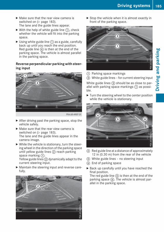
X Make sure that the rear view camera isswitched on (Y page 183).The lane and the guide lines appear.
X With the help of white guide line:, checkwhether the vehicle will fit into the parkingspace.
X Using white guide line: as a guide, carefullyback up until you reach the end position.Red guide line? is then at the end of theparking space. The vehicle is almost parallelin the parking space.
Reverseperpendicular parkingwith steer-ing input
X After driving past the parking space, stop thevehicle safely.
X Make sure that the rear view camera isswitched on (Y page 183).The lane and the guide lines appear in thecamera image.
X While the vehicle is stationary, turn the steer-ing wheel in the direction of the parking spaceuntil yellow guide lines; reach parkingspace marking:.Yellowguide lines;dynamically adapt to thecurrent steering input.
X Maintain the steering input and reverse care-fully.
X Stop the vehicle when it is almost exactly infront of the parking space.
: Parking space markings= White guide lines – for current steering inputWhite guide lines= should be as close to par-allel with parking space markings: as possi-ble.X Turn the steering wheel to the center positionwhile the vehicle is stationary.
? Red guide line at a distance of approximately12 in (0.30 m) from the rear of the vehicle
A White guide lines – no steering inputB End of parking spaceX Back up carefully until you have reached thefinal position.The red guide line? is then at the end of theparking spaceB. The vehicle is almost par-allel in the parking space.
Driving systems 185
Drivingandparking
Z

"Coupling up a trailer" function
: Vehicle center point on the yellow guide lineat a distance of approximately 3 ft (1.0 m)from the rear of the vehicle
; Trailer drawbarThis function is only available on vehicles with atrailer tow hitch.X Before coupling up a trailer, set the height oftrailer drawbar; so that it is slightly higherthan the ball coupling.
X Position the vehicle centrally in front of trailerdrawbar;.
= Trailer drawbar marker assistant? Symbol for the "Coupling up a trailer" func-
tionA Ball couplingB Red guide line at a distance of approximately
12 in (0.30 m) from the ball couplingX Select symbol? using the multimedia sys-tem controller.The "Coupling up a trailer" function is selec-ted. The distance specifications now onlyapply to objects that are at the same level asthe ball coupling.
X Reverse carefully, making sure that trailerdrawbar locating aid= points approximatelyin the direction of trailer drawbar;.
X Reverse carefully until trailer drawbar; rea-ches red guide lineB.The distance between trailer drawbar; andred guide lineB is now approximately 12 in(0.30 m).
X Couple up the trailer (Y page 204).
"Wide-angle" function
: Symbol for the wide-angle view function; Own vehicle= PARKTRONIC warning displaysYou can also use the rear view camera to selecta wide-angle view.When PARKTRONIC is operational (Y page 177),a symbol for your own vehicle appears in thedisplay of the multimedia system. If thePARKTRONIC warning displays are active, warn-ing displays= light up in themultimedia systemdisplay in yellow or red respectively.
Object detectionThe rear view camera helps detect moving andstationary objects. If an object (person, vehicleor other obstacle) is detected, this object ismarked with a bar. Objects located some dis-tance from the vehicle away are marked with ayellow bar. If the distance to the object is verysmall, the bar is displayed in red.Object detection only works in wide-angle view.To ensure that you can use the function, it mustbe switched on in the multimedia system (seethe Digital Operator's Manual).
186 Driving systemsDrivingandparking
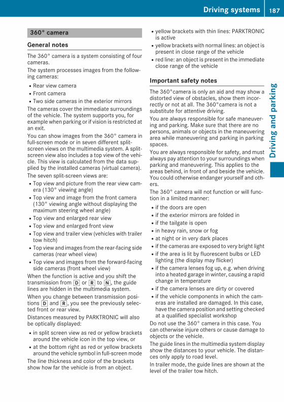
360° camera
General notesThe 360° camera is a system consisting of fourcameras.The system processes images from the follow-ing cameras:RRear view cameraRFront cameraRTwo side cameras in the exterior mirrorsThe cameras cover the immediate surroundingsof the vehicle. The system supports you, forexample when parking or if vision is restricted atan exit.You can show images from the 360° camera infull-screen mode or in seven different split-screen views on the multimedia system. A split-screen view also includes a top view of the vehi-cle. This view is calculated from the data sup-plied by the installed cameras (virtual camera).The seven split-screen views are:RTop view and picture from the rear view cam-era (130° viewing angle)RTop view and image from the front camera(130° viewing angle without displaying themaximum steering wheel angle)RTop view and enlarged rear viewRTop view and enlarged front viewRTop view and trailer view (vehicles with trailertow hitch)RTop view and images from the rear-facing sidecameras (rear wheel view)RTop view and images from the forward-facingside cameras (front wheel view)
When the function is active and you shift thetransmission fromh ork toi, the guidelines are hidden in the multimedia system.When you change between transmission posi-tionsh andk, you see the previously selec-ted front or rear view.Distances measured by PARKTRONIC will alsobe optically displayed:Rin split screen view as red or yellow bracketsaround the vehicle icon in the top view, orRat the bottom right as red or yellow bracketsaround the vehicle symbol in full-screenmode
The line thickness and color of the bracketsshow how far the vehicle is from an object.
Ryellow brackets with thin lines: PARKTRONICis activeRyellow brackets with normal lines: an object ispresent in close range of the vehicleRred line: an object is present in the immediateclose range of the vehicle
Important safety notesThe 360°camera is only an aid and may show adistorted view of obstacles, show them incor-rectly or not at all. The 360°camera is not asubstitute for attentive driving.You are always responsible for safe maneuver-ing and parking. Make sure that there are nopersons, animals or objects in the maneuveringarea while maneuvering and parking in parkingspaces.You are always responsible for safety, and mustalways pay attention to your surroundings whenparking and maneuvering. This applies to theareas behind, in front of and beside the vehicle.You could otherwise endanger yourself and oth-ers.The 360° camera will not function or will func-tion in a limited manner:Rif the doors are openRif the exterior mirrors are folded inRif the tailgate is openRin heavy rain, snow or fogRat night or in very dark placesRif the cameras are exposed to very bright lightRif the area is lit by fluorescent bulbs or LEDlighting (the display may flicker)Rif the camera lenses fog up, e.g. when drivinginto a heated garage in winter, causing a rapidchange in temperatureRif the camera lenses are dirty or coveredRif the vehicle components in which the cam-eras are installed are damaged. In this case,have the camera position and setting checkedat a qualified specialist workshop
Do not use the 360° camera in this case. Youcan otherwise injure others or cause damage toobjects or the vehicle.The guide lines in themultimedia system displayshow the distances to your vehicle. The distan-ces only apply to road level.In trailer mode, the guide lines are shown at thelevel of the trailer tow hitch.
Driving systems 187
Drivingandparking
Z

The camera in the rear area is protected bymeans of a flap. This flap opens when the 360°camera is activated. Observe the notes oncleaning (Y page 316). For technical reasons,the flap may remain open briefly after the 360°camera has been deactivated.The field of vision and other functions of thecamera system may be restricted due to addi-tional attachments (e.g. license plate holder,rear bicycle carrier).On vehicles with height-adjustable chassis,depending on technical conditions, leaving thestandard height can result in:Rinaccuracies in the guide linesRinaccuracies in the display of generatedimages (top view)
Activation conditionsThe image from the 360° camera appears if:Rthe multimedia system is switched onRthe 360° Camera function is switched onIf you are driving faster than at a moderatespeed and you turn on the 360° camera, a warn-ing message appears.The warning message disappears if:Ryou are again driving at amoderate speed The360° camera is then activatedRthe message is confirmed with the% but-ton
Switching the 360° camera on and offusing the button
X To switch on: press button:.The following appears depending on whethergearh ork is selected:
Ra split screen with top view and the imagefrom the front camera orRa split screen with top view and the imagefrom the rear view camera
X To switch off: press button:.
Activating the 360° camera usingreverse gearThe 360° camera images can be automaticallydisplayed by engaging reverse gear.X Make sure that the Activation by R gearfunction is selected in the multimedia system(see the Digital Operator's Manual).
X To show the 360° camera image: engagereverse gear.The multimedia system shows the areabehind the vehicle in split-screen mode. Yousee the top view of the vehicle and the imagefrom the rear view camera.You cannot stop the 360° camera display ifreverse gear is engaged.
Selecting the split-screen view or fullscreen modeSwitching between split screen views:X To switch to the line with the vehicle icons:slide5 the controller.
X To select a vehicle icon: turn the controller.Switching to full screen mode:X Turn and press 180° Viewwith the controller.The full screen option is only available in the fol-lowing views:RTop view with picture from the rear view cam-eraRTop view with picture from the front camera
Multimedia display
Important safety notesThe camera system may show a distorted viewof obstacles, show them incorrectly or not at all.Obstacles are not shown by the system in thefollowing locations:Runder the front and rear bumpersRvery close to the front and rear bumpersRin the area immediately above the tailgatehandle
188 Driving systemsDrivingandparking
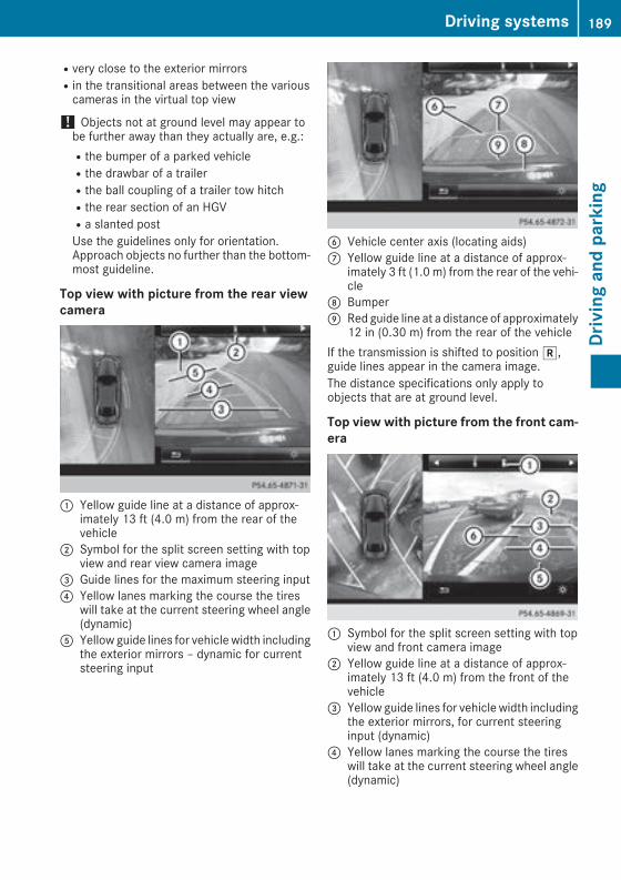
Rvery close to the exterior mirrorsRin the transitional areas between the variouscameras in the virtual top view
! Objects not at ground level may appear tobe further away than they actually are, e.g.:Rthe bumper of a parked vehicleRthe drawbar of a trailerRthe ball coupling of a trailer tow hitchRthe rear section of an HGVRa slanted postUse the guidelines only for orientation.Approach objects no further than the bottom-most guideline.
Top view with picture from the rear viewcamera
: Yellow guide line at a distance of approx-imately 13 ft (4.0 m) from the rear of thevehicle
; Symbol for the split screen setting with topview and rear view camera image
= Guide lines for the maximum steering input? Yellow lanes marking the course the tires
will take at the current steering wheel angle(dynamic)
A Yellow guide lines for vehicle width includingthe exterior mirrors – dynamic for currentsteering input
B Vehicle center axis (locating aids)C Yellow guide line at a distance of approx-
imately 3 ft (1.0 m) from the rear of the vehi-cle
D BumperE Red guide line at a distance of approximately
12 in (0.30 m) from the rear of the vehicleIf the transmission is shifted to positionk,guide lines appear in the camera image.The distance specifications only apply toobjects that are at ground level.
Top view with picture from the front cam-era
: Symbol for the split screen setting with topview and front camera image
; Yellow guide line at a distance of approx-imately 13 ft (4.0 m) from the front of thevehicle
= Yellow guide lines for vehicle width includingthe exterior mirrors, for current steeringinput (dynamic)
? Yellow lanes marking the course the tireswill take at the current steering wheel angle(dynamic)
Driving systems 189
Drivingandparking
Z

A Red guide line at a distance of approximately12 in (0.30 m) from the front of the vehicle
B Yellow guide line at a distance of approx-imately 3 ft (1.0 m) from the front of thevehicle
Top view and enlarged rear view
: Symbol for the split screen setting with topview and rear view camera image enlarged
; Red guide line at a distance of approximately12 in (0.30 m) from the rear of the vehicle
This view assists you in estimating the distanceto the vehicle behind you.
i This setting can also be selected as anenlarged front view.
Top view with image from the side cam-eras
: Symbol for the top view and forward-facingside camera setting
; Yellow guide line for the vehicle widthincluding the exterior mirrors (right side ofvehicle)
= Yellow guide line for the vehicle widthincluding the exterior mirrors (left side ofvehicle)
i You can also select the side camera settingfor the rear-facing view.
"Coupling up a trailer" function
: Vehicle center point on the yellow guide lineat a distance of approximately 3 ft (1.0 m)from the rear of the vehicle
; Trailer drawbar= Red guide line at a distance of approximately
12 in (0.30 m) from the rear of the vehicleX Set the height of trailer drawbar; so that itis slightly higher than the ball coupling.
X Position the vehicle centrally in front of trailerdrawbar;.
For technical reasons, the ball couplingB ofthe trailer tow hitch on the multimedia systemdisplay is either only partially visible or not visi-ble at all.X Select symbol? using the controller.The "Coupling up a trailer" function is selec-ted. The distance specifications now onlyapply to objects that are at the same level asthe ball coupling.
X Reverse carefully, making sure that trailerdrawbar locating aidA points approximatelyin the direction of the trailer drawbar.
190 Driving systemsDrivingandparking

X Reverse carefully until the trailer drawbar rea-ches red guide lineC.The distance between the trailer drawbar andred guide lineC is now approximately 12 in(0.30 m).
X Couple up the trailer (Y page 204).The lines are shown at the level of the trailer towhitch.
180° view
: Symbol for the full screen setting with rearview camera image
; Own vehicle= PARKTRONIC warning displays
i 180° view can also be selected as frontview.
Select this view when you are driving out of anexit and the view of crossing traffic is restricted,for example.If you select the% symbol in the display andconfirmwith the controller, the split-screen viewappears.
Exiting 360° camera display modeX Shift the transmission to positionj.orX Drive forwards at a speed greater than 6 mph(10 km/h).The 360° camera display is stopped.The view that was active before the 360°camera was displayed appears in the multi-media system display. You can also stop the360° camera display split-screen view byselecting the% symbol in the display andthen confirming with the COMAND controller.You cannot stop the 360° camera display ifthe transmission positionk is selected.
ATTENTION ASSIST
General notesATTENTION ASSIST helps you during long,monotonous journeys, such as on highways. It isactive in the 37 mph (60 km/h) to 124 mph(200 km/h) speed range. If ATTENTION ASSISTdetects typical indicators of fatigue or increas-ing lapses in concentration on the part of thedriver, it suggests taking a break.
Important safety notesATTENTION ASSIST is only an aid to the driver. Itmight not always recognize fatigue or increasinginattentiveness in time or fail to recognize themat all. The system is not a substitute for a well-rested and attentive driver.The functionality of ATTENTION ASSIST isrestricted and warnings may be delayed or notoccur at all:Rif the length of the journey is less than approx-imately 30 minutesRif the road condition is poor, e.g. if the surfaceis uneven or if there are potholesRif there is a strong side windRif you have adopted a sporty driving style withhigh cornering speeds or high rates of accel-erationRif you are predominantly driving at a speedbelow 37 mph (60 km/h) or above 124 mph(200 km/h)Rif you are drivingwith DISTRONIC PLUSSteer-ing Assist activatedRif the time has been set incorrectlyRin active driving situations, such as when youchange lanes or change your speed
The ATTENTION ASSIST tiredness assessmentis deleted and restarted when continuing thejourney, if:Ryou switch off the engineRyou take off your seat belt and open the driv-er's door, e.g. for a change of drivers or totake a break
Driving systems 191
Drivingandparking
Z

Displaying the attention level
In the Assistance menu (Y page 220) of the on-board computer, you can call up the current sta-tus information.X Select the Assistance display for ATTENTIONASSIST using the on-board computer(Y page 219).
The following information appears:Rthe length of the journey since the last break.Rthe attention level determined by ATTENTIONASSIST (Attention Level), displayed in abar display in five levels from high to low.Rif ATTENTION ASSIST is unable to calculatethe attention level and cannot issue a warn-ing, the System Suspended messageappears. The bar display then changes thedisplay, e.g. if you are driving at a speed below37 mph (60 km/h) or above 124 mph(200 km/h).
Activating ATTENTION ASSISTX Activate ATTENTION ASSIST using the on-board computer (Y page 221).The system determines the attention level ofthe driver depending on the setting selected:
Selection Standard: the sensitivity with whichthe system determines the attention level is setto normal.Selection Sensitive: the sensitivity is sethigher. The attention level detected by AttentionAssist is adapted accordingly and the driver iswarned earlier.When ATTENTION ASSIST is deactivated, theé symbol appears in the multifunction dis-play in the assistance graphic display.WhenATTENTIONASSIST has been deactivated,it is automatically reactivated after the enginehas been stopped. The sensitivity selected cor-
responds to the last selection activated (stand-ard/sensitive).
Warning in the multifunction displayIf fatigue or increasing lapses in concentrationare detected, a warning appears in the multi-function display: ATTENTION ASSIST Take aBreak!.In addition to the message shown in the multi-function display, you will then hear a warningtone.X If necessary, take a break.X Confirm the message by pressing theabutton on the steering wheel.
On long journeys, take regular breaks in goodtime to allow yourself to rest properly. If you donot take a break and ATTENTION ASSIST con-tinues to detect increasing lapses in concentra-tion, you will be warned again after 15 minutesat the earliest. This will only happen if ATTEN-TION ASSIST still detects typical indicators offatigue or increasing lapses in concentration.Vehicles with COMANDmultimedia system:if a warning appears in themultifunction display,a service station search is performed in the mul-timedia system. You can select a service stationand navigation to this service station will thenbegin. This function can be activated and deac-tivated in the COMANDmultimedia system (seethe Digital Operator's Manual).
Traffic Sign Assist
General notesTraffic Sign Assist displays the maximum speedpermitted to the driver in the instrument cluster.The data and general traffic regulations stored inthe navigation system are used to determine thecurrent speed limit.Traffic Sign Assist is a map-based system, andfor this reason, traffic signs put up temporarily(e.g. near roadworks) are not detected. There isalso no display for changing traffic signs.Traffic signs with a restriction indicated by anadditional sign (e.g. in wet conditions) are alsoshown.
192 Driving systemsDrivingandparking

The sign indicating the end of a restriction onlyappears with the restriction in the instrumentcluster when:RThe regulation must be observed with therestriction, orRTraffic Sign Assist is unable to determinewhether the restriction applies
If Traffic Sign Assist is unable to determine amaximumpermitted speed fromany of the avail-able sources, no speed limit appears in theinstrument cluster either.
Traffic Sign Assist is not available in all coun-tries. In this case, display: appears in theassistance graphic (Y page 219).
Important safety notesTraffic SignAssist is only an aid and is not alwaysable to correctly display speed limits. Trafficsigns always have priority over the Traffic SignAssist display.The system may be either functionally impairedor temporarily unavailable if the information inthe digital streetmap of the navigation system isincorrect or out of date.
Instrument cluster display
Displaying the assistance graphicX Call up the assistance graphic display func-tion using the on-board computer(Y page 219).Detected traffic signs appear in the instru-ment cluster.
Speed limit with unknown restriction
: Maximum permitted speed; Maximum permitted speed for vehicles for
which the restriction in the additional sign isrelevant
= Additional sign for unknown restrictionA maximum permitted speed of 80 mph(80 km/h) and a speed limit of 60 mph(60 km/h) with an unknown restriction apply.The unit for the speed limit (km/h or mph)depends on the country in which you are driving.It is generally neither shown on the traffic signnor on the instrument cluster but must be takeninto account when observing the maximum per-mitted speed.
Lane Tracking package
General notesThe Lane Tracking package consists of BlindSpot Assist (Y page 193) and Lane KeepingAssist (Y page 195).
Blind Spot Assist
General notesBlind Spot Assist monitors the areas on eitherside of the vehicle that are not visible to thedriver with two lateral, rear-facing radar sen-sors. A warning lamp lights up in the exteriormirrors and draws your attention to vehiclesdetected in the monitored area. If you thenswitch on the corresponding turn signal tochange lane, you will also receive an optical andaudible warning.Blind Spot Assist supports you from a speed ofapproximately 20 mph (30 km/h).
Driving systems 193
Drivingandparking
Z

Important safety notesG WARNINGBlind Spot Assist does not react to:Rvehicles overtaken too closely on the side,placing them in the blind spot areaRvehicles which approach with a large speeddifferential and overtake your vehicle
As a result, Blind Spot Assist may not givewarnings in such situations. There is a risk ofan accident.Always observe the traffic conditions care-fully, and maintain a safe lateral distance.
Blind Spot Assist is only an aid. It may fail todetect some vehicles and is no substitute forattentive driving. Always ensure that there issufficient distance to the side for other roadusers and obstacles.
i USA only:This device has been approved by the FCC asa "Vehicular Radar System". The radar sensoris intended for use in an automotive radarsystem only. Removing, tampering with, oraltering the device will void any warranties,and is not permitted by the FCC. Do not tam-per with, alter, or use in any non-approvedway.Any unauthorized modification to this devicecould void the user’s authority to operate theequipment.
Radar sensorsThe radar sensors for Blind Spot Assist are inte-grated into the rear bumper. Make sure that thebumpers are free from dirt, ice or slush. Thesensors must not be covered, for example bycycle racks or overhanging loads. Following asevere impact or in the event of damage to thebumpers, have the function of the radar sensorschecked at a qualified specialist workshop.Blind Spot Assist may no longer work properly.
Monitoring areaIn particular, the detection of obstacles can beimpaired if:Rthere is dirt on the sensors or anything elsecovering the sensorsRthere is poor visibility, e.g. due to fog, heavyrain, snow or spray
Rthere are narrow vehicles, e.g. motorcycles orbicyclesRthe road has very wide lanesRthe road has narrow lanesRyou are not driving in the middle of the laneRthere are barriers or other road boundariesVehicles in the monitoring range are then notindicated.
At a distance of around1.6 ft (0.5m); from thevehicle, Blind Spot Assist monitors the area upto 10 ft (3 m) next to= and behind: yourvehicle, as shown in the picture.If the lanes are narrow, vehicles driving in thelane beyond the lane next to your vehiclemay beindicated, especially if the vehicles are not driv-ing in the middle of their lane. This may be thecase if there are vehicles driving at the inneredge of their lanes.Due to the nature of the system:Rwarnings may be issued in error when drivingclose to crash barriers or similar solid lanebordersRwarnings may be interrupted when drivingalongside long vehicles, such as trucks, for aprolonged time
194 Driving systemsDrivingandparking

Warning lamp
: Warning lampBlind Spot Assist is not active at speeds belowapproximately 20 mph (30 km/h). Vehicles inthe monitoring range are then not indicated.If a vehicle is detected within the blind spotmonitoring range at speeds above 20 mph(30 km/h), warning lamp: on the correspond-ing side lights up red. This warning is alwaysemitted when a vehicle enters the blind spotmonitoring range from behind or from the side.When you overtake a vehicle, the warning onlyoccurs if the difference in speed is less than7 mph (12 km/h).If you select the reverse gear, Blind Spot Assistis not operational.The brightness of the warning lamps is auto-matically adapted to the brightness of the sur-roundings.
Collision warningIf a vehicle is detected in themonitoring range ofBlind Spot Assist and you switch on the corre-sponding turn signal, a double warning tonesounds. The red warning lamp flashes on therelevant exterior mirror. If the turn signalremains on, detected vehicles are indicated bythe flashing of the red warning lamp on the exte-rior mirror. There are no further warning tones.
Switching on Blind Spot AssistX Make sure that Blind Spot Assist is activatedin the on-board computer (Y page 221).
X Turn the SmartKey to position2 in the igni-tion lock.The red warning lamps on the exterior mirrorslight up until the engine is started.
Display in the assistance graphic
When Blind Spot Assist is activated, gray radarwaves propagating backwards appear next tothe vehicle in the assistance display in the mul-tifunction display (Y page 219). Above a speedof 20 mph (30 km/h), the color of the radarwaves in the assistance graphic changes togreen:. Blind Spot Assist is then ready for use.
Towing a trailerWhen you attach a trailer, make sure you havecorrectly established the electrical connection.This can be accomplished by checking the trailerlighting. In this event, Blind Spot Assist is deac-tivated. The Blind Spot Assist Not Avail‐able When Towing a Trailer See Opera‐tor's Manual message appears in the multi-function display.
Lane Keeping Assist
General notes
LaneKeepingAssistmonitors the area in front ofyour vehicle by means of multifunction cam-era: which is attached behind the top of thewindshield. Active Lane Keeping Assist detectslane markings on the road and can warn youbefore you leave your lane unintentionally.
Driving systems 195
Drivingandparking
Z

This function is available in the range between40mph and 120mph (60 km/h and 200 km/h).A warning may be given if a front wheel passesover a lanemarking. It will warn you bymeans ofintermittent vibration in the steering wheel forup to 1.5 seconds.
Important safety notesG WARNINGLane Keeping Assist may not always clearlyrecognize lane markings.In this case, Lane Keeping Assist may:Rgive an unnecessary warningRnot give a warningThere is a risk of an accident.Always pay particular attention to the trafficsituation and stay in lane, in particular ifwarned by Lane Keeping Assist.
G WARNINGThe Lane Keeping Assist warning does notreturn the vehicle to the original lane. There isa risk of an accident.You should always steer, brake or accelerateyourself, in particular if warned by Lane Keep-ing Assist.
Lane Keeping Assist can neither reduce the riskof an accident if you fail to adapt your drivingstyle nor override the laws of physics. LaneKeeping Assist cannot take into account theroad, traffic and weather conditions. Lane Keep-ing Assist is merely an aid. You are responsiblefor the distance to the vehicle in front, for vehi-cle speed, for braking in good time and for stay-ing in your lane.The Lane Keeping Assist does not keep the vehi-cle in the lane.The systemmay be impaired ormay not functionif:Rthere is poor visibility, e.g. due to insufficientillumination of the road, or due to snow, rain,fog or sprayRthere is glare, e.g. from oncoming traffic, thesun or reflection from other vehicles (e.g. ifthe road surface is wet)Rthewindshield is dirty, fogged up, damaged orcovered, for instance by a sticker, in the vicin-ity of the camera
Rthere are no, several or unclear lanemarkingsfor a lane, e.g. in areas with road constructionworkRthe lanemarkings are worn away, dark or cov-ered up, e.g. by dirt or snowRthe distance to the vehicle in front is too smalland the lane markings thus cannot be detec-tedRthe lane markings change quickly, e.g. lanesbranch off, cross one another or mergeRthe road is narrow and windingRthere are highly variable shade conditions onthe roadway
Activating/deactivating Lane KeepingAssist
X To activate: press button;.Indicator lamp: lights up. The Lane Keep‐ing Assist Onmessage appears in the mul-tifunction display. If all conditions have beensatisfied, there may be a warning.If you drive at speeds above 40 mph(60 km/h) and lane markings are detected,the lines in the assistance graphics display(Y page 219) are shown in green. Lane Keep-ing Assist is ready for use.
X To deactivate: press button;.Indicator lamp: goes out. Lane KeepingAssist is deactivated. The Lane KeepingAssist Off message appears in the multi-function display.
Selecting Standard or Adaptive settingX In the DriveAssist menu on the on-boardcomputer, select the Lane Keeping Assistfunction (Y page 221).
X Select Standard or Adaptive.Standard
196 Driving systemsDrivingandparking

When Standard is selected, no warning vibra-tion occurs if:Ryou switch on the turn signals. In this event,the warnings are suppressed for a certainperiod of time.Ra driving safety system intervenes, e.g. ABS,BAS or ESP®.
AdaptiveWhen Adaptive is selected, no warning vibra-tion occurs if:Ryou switch on the turn signals. In this event,the warnings are suppressed for a certainperiod of time.Ra driving safety system intervenes, e.g. ABS,BAS or ESP®.Ryou accelerate hard, e.g. kickdown.Ryou brake hard.Ryou steer actively, e.g. swerve to avoid anobstacle or change lanes quickly.Ryou cut the corner on a sharp bend.In order that you are warned only when neces-sary and in good time if you cross the lanemark-ing, the system recognizes certain conditionsand warns you accordingly.The warning vibration occurs earlier if:Ryou approach the outer lane marking on abend.Rthe road has very wide lanes, e.g. a highway.Rthe system detects solid lane markings.The warning vibration occurs later if:Rthe road has narrow lanes.Ryou cut the corner on a bend.
Driving Assistance PLUS package
General notesThe Driving Assistance PLUS package consistsof DISTRONIC PLUS (Y page 164), Active BlindSpot Assist (Y page 197) and Active Lane Keep-ing Assist (Y page 200).
Active Blind Spot Assist
General notesActive Blind Spot Assist uses a radar sensorsystem, pointed toward the rear of the vehicle,to monitor the area to the sides of the vehiclewhich the driver is unable to see. Awarning lamp
lights up in the exterior mirrors and draws yourattention to vehicles detected in the monitoredarea. If you then switch on the correspondingturn signal to change lane, you will also receivean optical and audible warning. If a risk of lateralcollision is detected, corrective braking mayhelp you avoid a collision. Before a course-cor-recting brake application, Active Blind SpotAssist evaluates the space in the direction oftravel and at the sides of the vehicle. For this,Active Blind Spot Assist uses the forward-facingradar sensors.Active Blind Spot Assist supports you from aspeed of approximately 20 mph (30 km/h).
Important safety notesActive Blind Spot Assist is only an aid and is nota substitute for attentive driving.
G WARNINGActive Blind Spot Assist does not react to:Rvehicles overtaken too closely on the side,placing them in the blind spot areaRvehicles which approach with a large speeddifferential and overtake your vehicle
As a result, Active Blind Spot Assist may nei-ther give warnings nor intervene in such sit-uations. There is a risk of an accident.Always observe the traffic conditions care-fully, and maintain a safe lateral distance.
i USA only: This device has been approved bythe FCC as a "Vehicular Radar System". Theradar sensor is intended for use in an auto-motive radar system only. Removal, tamper-ing, or altering of the device will void any war-ranties, and is not permitted by the FCC. Donot tamper with, alter, or use in any non-approved way.Any unauthorized modification to this devicecould void the user's authority to operate theequipment.
i Canada only: This device complies withRSS-210 of Industry Canada. Operation issubject to the following two conditions:1. This device may not cause interference,and2. This device must accept any interferencereceived, including interference that maycause undesired operation of the device.
Driving systems 197
Drivingandparking
Z

Removal, tampering, or altering of the devicewill void any warranties, and is not permitted.Do not tamper with, alter, or use in any non-approved way.Any unauthorized modification to this devicecould void the user's authority to operate theequipment.
Radar sensorsThe Active Blind Spot Assist radar sensors areintegrated into the front and rear bumpers andbehind a cover in the radiator trim. Make surethat the bumpers and the cover in the radiatorgrill are free of dirt, ice or slush. The rear sensorsmust not be covered, for example by cycle racksor overhanging cargo. Following a severe impactor in the event of damage to the bumpers, havethe function of the radar sensors checked at aqualified specialist workshop. Active Blind SpotAssist may otherwise no longer work properly.
Monitoring areaG WARNINGActive Blind Spot Assist does not detect alltraffic situations and road users. There is arisk of an accident.Always make sure that there is sufficient dis-tance on the side for other traffic or obstacles.
At a distance of approximately 1.6 ft (0.5 m);from the vehicle, Active Blind Spot Assist mon-itors the area up to 10 ft (3 m) next to= andbehind: your vehicle, as shown in the picture.
The detection of obstacles can be impaired inthe case of:Rthere is dirt on the sensors or anything elsecovering the sensorsRpoor visibility, e.g. due to rain, snow or sprayVehicles in the monitoring range are then notindicated.Active Blind Spot Assist may not detect narrowvehicles, such as motorcycles or bicycles, ormay only detect them too late.If the lanes are narrow, vehicles driving in thelane beyond the lane next to your vehiclemay beindicated, especially if the vehicles are not driv-ing in the middle of their lane. This may be thecase if there are vehicles at the inner edge ofyour lane.Due to the nature of the system:Rwarnings may be issued in error when drivingclose to crash barriers or similar solid laneborders.Rwarnings may be interrupted when you aredriving alongside particularly long vehicles,such as trucks, for a prolonged time.
Warning lamp
: Warning lampActive Blind Spot Assist is not operational atspeeds below approximately 20mph (30 km/h).Vehicles in the monitoring range are then notindicated.If a vehicle is detected within the blind spotmonitoring range at speeds above 20 mph(30 km/h), warning lamp: on the correspond-ing side lights up red. This warning is alwaysemitted when a vehicle enters the blind spotmonitoring range from behind or from the side.When you overtake a vehicle, the warning onlyoccurs if the difference in speed is less than7 mph (12 km/h).
198 Driving systemsDrivingandparking

If you select the reverse gear, Active Blind SpotAssist is not operational.The brightness of the warning lamps is auto-matically adapted to the brightness of the sur-roundings.
When Active Blind Spot Assist is activated, grayradar waves propagating backward appear nextto the vehicle in the assistance display in themultifunction display. Above a speed of 20 mph(30 km/h), the color of the radar waves in theassistance display changes to green;. ActiveBlind Spot Assist is then ready for use.
Visual and acoustic collision warningIf you switch on the turn signals to change lanesand a vehicle is detected in the side monitoringrange, you receive a visual and acoustic collisionwarning. You will then hear a double warningtone and redwarning lamp: flashes. If the turnsignal remains on, detected vehicles are indica-ted by the flashing of red warning lamp:.There are no further warning tones.
Course-correcting brake applicationIf Active Blind Spot Assist detects a risk of a lat-eral collision in the monitoring range, a course-correcting brake application is carried out. Thisis meant to assist you in avoiding a collision.
G WARNINGA course-correcting brake application cannotalways prevent a collision. There is a risk of anaccident.Always steer, brake or accelerate yourself,especially if Active Blind Spot Assist warnsyou ormakes a course-correcting brake appli-cation. Always maintain a safe distance at thesides.
If a course-correcting brake application occurs,red warning lamp: flashes in the exterior mir-ror and a double warning tone sounds. In addi-tion, a display underlining the danger of a sidecollision appears in the multifunction display.In very rare cases, the system may make aninappropriate brake application. A course-cor-recting brake application may be interrupted atany time by countersteering slightly or acceler-ating.The course-correcting brake application is avail-able in the speed range between 20 mph(30 km/h) and 120 mph (200 km/h).Either no braking application, or a course-cor-recting brake application adapted to the drivingsituation occurs if:Rthere are vehicles or obstacles, e.g. crashbarriers, located on both sides of your vehicle.Ra vehicle approaches you too closely at theside.Ryou have adopted a sporty driving style withhigh cornering speeds.Ryou clearly brake or accelerate.Ra driving safety system intervenes, e.g. ESP®or PRE-SAFE® Brake.RESP® is switched off.Ra loss of tire pressure or a defective tire isdetected.
Switching on Active Blind Spot AssistX Make sure that Active Blind Spot Assist isactivated in the on-board computer(Y page 221).
X Switch on the ignition.Warning lamps: in the exterior mirrors lightup red for approximately 1.5 seconds.Gray radar waves propagating backwardsappear next to the vehicle in the assistancegraphic in the multifunction display;.Above a speed of 20mph (30 km/h), the colorof the radar waves in the assistance displaychanges to green;. Active Blind Spot Assistis then ready for use.
Driving systems 199
Drivingandparking
Z

Active Lane Keeping Assist
General notes
Active Lane Keeping Assist monitors the area infront of your vehicle by means of multifunctioncamera: at the top of the windshield. Variousdifferent areas to the front, rear and side of yourvehicle are also monitored with the aid of theradar sensor system. Active Lane KeepingAssist detects lane markings on the road andcan warn you before you leave your lane unin-tentionally. If you do not react to the warning, alane-correcting application of the brakes canbring the vehicle back into the original lane.This function is available in the range between40mph and 120mph (60 km/h and 200 km/h).
Important safety notesIf you fail to adapt your driving style, Active LaneKeeping Assist can neither reduce the risk of anaccident nor override the laws of physics. ActiveLane Keeping Assist cannot take account ofroad and weather conditions. It may not recog-nize traffic situations. Active Lane KeepingAssist is only an aid. You are responsible for thedistance to the vehicle in front, for vehiclespeed, for braking in good time and for staying inyour lane.Active Lane Keeping Assist cannot continuouslykeep your vehicle in its lane.
G WARNINGActive Lane Keeping Assist cannot alwaysclearly detect lane markings.
In such cases, Active Lane Keeping Assistcan:Rgive an unnecessary warning and thenmake a course-correcting brake applicationto the vehicleRnot give a warning or interveneThere is a risk of an accident.Always pay particular attention to the trafficsituation and keep within the lane, especiallyif Active Lane Keeping Assist alerts you. Ter-minate the intervention in a non-critical driv-ing situation.
The systemmay be impaired ormay not functionif:Rthere is poor visibility, e.g. due to insufficientillumination of the road, or due to snow, rain,fog or sprayRthere is glare, e.g. from oncoming traffic, thesun or reflection from other vehicles (e.g. ifthe road surface is wet)Rthewindshield is dirty, fogged up, damaged orcovered, for instance by a sticker, in the vicin-ity of the cameraRthe radar sensors in the front or rear bumpersor the radiator trim are dirty, e.g. obscured bysnowRthere are no, several or unclear lanemarkingsfor a lane, e.g. in areas with road constructionworkRthe lanemarkings are worn away, dark or cov-ered up, e.g. by dirt or snowRthe distance to the vehicle in front is too smalland the lane markings thus cannot be detec-tedRthe lane markings change quickly, e.g. lanesbranch off, cross one another or mergeRthe road is narrow and windingRthere are highly variable shade conditions onthe roadway
If no vehicle is detected in the adjacent lane andbroken lanemarkings are detected, no lane-cor-recting brake application is made.
Warning vibration in the steering wheelA warning may be given if a front wheel passesover a lanemarking. It will warn you bymeans ofintermittent vibration in the steering wheel forup to 1.5 seconds.
200 Driving systemsDrivingandparking

Lane-correcting brake applicationIf you leave your lane, under certain circumstan-ces the vehicle will brake briefly on one side.This ismeant to assist you in bringing the vehicleback to the original lane.
G WARNINGA lane-correcting brake application cannotalways bring the vehicle back into the originallane. There is a risk of an accident.Always steer, brake or accelerate yourself,especially if Active Lane Keeping Assist warnsyou or makes a lane-correcting brake appli-cation.
If a lane-correcting brake application occurs,display: appears in the multifunction display.The brake application also slightly reduces vehi-cle speed.A lane-correcting brake application can bemadeafter driving over a lane marking detected asbeing solid or broken. Before this, a warningmust be given bymeans of intermittent vibrationin the steering wheel. In addition, a lane withlane markings on both sides must be recog-nized.In the case of a broken lane marking beingdetected, a lane-correcting brake applicationcan only be made if a vehicle has been detectedin the adjacent lane. Oncoming vehicles, over-taking vehicles and vehicles in adjacent lanescan be detected.A further lane-correcting brake application canonly occur after your vehicle has returned to theoriginal lane.No lane-correcting brake application occurs if:Ryou clearly and actively steer, brake or accel-erate.Ryou cut the corner on a sharp bend.
Ryou have switched on the turn signal.Ra driving safety system intervenes, e.g. ESP®,PRE-SAFE® Brake or Active Blind Spot Assist.Ryou have adopted a sporty driving style withhigh cornering speeds or high rates of accel-eration.RESP® is switched off.Rthe transmission is not in positionh.Ron vehicles with a trailer tow hitch, the elec-trical connection to the trailer has been cor-rectly established.Ra loss of tire pressure or a defective tire hasbeen detected and displayed.Ran obstacle has been detected in the lane inwhich you are driving.
Active Lane Keeping Assistmay not detect otherroad users or traffic situations. An inappropriatebrake applicationmay be interrupted at any timeif you:Rsteer slightly in the opposite direction.Rswitch on the turn signal.Ryou brake or accelerate significantly.A lane-correcting brake application is interrup-ted automatically if:Ra driving safety system intervenes, e.g. ESP®,PRE-SAFE® Brake or Active Blind Spot Assist.Rlane markings are no longer detected.
Activating/deactivating Active LaneKeeping Assist
X To activate: press button;.Indicator lamp: lights up. The Lane Keep‐ing Assist On message appears on themultifunction display. If all conditions havebeen satisfied, a warning or steering inter-vention may be made.If you drive at speeds above 40 mph(60 km/h) and lane markings are detected,
Driving systems 201
Drivingandparking
Z
the lines in the assistance graphic(Y page 219) appear in green. Active LaneKeeping Assist is ready for use.
X To deactivate: press button;.Indicator lamp: goes out. The Active LaneKeeping Assist is deactivated. The LaneKeeping Assist Off message appears onthe multifunction display.
Selecting Standard or Adaptive settingX In the DriveAssist menu on the on-boardcomputer, select the Active Lane Keep‐ing Assist function (Y page 221).
X Select setting Standard or Adaptive.When Standard is selected, nowarning vibra-tion occurs if:Ryou switch on the turn signals. In this event,the warnings are suppressed for a certainperiod of time.Ra driving safety system intervenes, such asABS, BAS or ESP®.
When Adaptive is selected, nowarning vibra-tion occurs if:Ryou switch on the turn signals. In this event,the warnings are suppressed for a certainperiod of time.Ra driving safety system intervenes, e.g.ABS, BAS or ESP®.Ryou accelerate hard, e.g. kickdown.Ryou brake hard.Ryou steer actively, e.g. swerve to avoid anobstacle or change lanes quickly.Ryou cut the corner on a sharp bend.
In order that you are warned only when neces-sary and in good time if you cross the lanemark-ing, the system recognizes certain conditionsand warns you accordingly.The warning vibration occurs earlier if:Ryou approach the outer lane marking on abend.Rthe road has very wide lanes, e.g. a highway.Rthe system detects solid lane markings.The warning vibration occurs later if:Rthe road has narrow lanes.Ryou cut the corner on a bend.
Towing a trailerWhen you attach a trailer, make sure you havecorrectly established the electrical connection.
This can be accomplished by checking the trailerlighting.
Towing a trailer
Important safety notes
G WARNINGInstalling an unsuitable ball coupling mayresult in overloading of the trailer tow hitchand the rear axle. This applies especially if theball coupling in question is longer or angleddifferently. This could seriously impair thedriving characteristics and the trailer cancome loose. There is a risk of an accident.You should only ever install a ball couplingthat has the permissible dimensions and thatis designed to meet your trailer-towingrequirements. Do not modify the ball couplingor the trailer tow hitch.
You will find the values approved by the manu-facturer on the vehicle identification plates andthose for the towing vehicle under "Technicaldata" (Y page 371).
G WARNINGWhen the vehicle/trailer combination beginsto lurch, you could lose control of it. The vehi-cle/trailer combination could even rollover.There is a risk of an accident.On no account should you attempt tostraighten up the vehicle/trailer combinationby increasing the speed. Reduce vehiclespeed and do not countersteer. Apply thebrake as necessary.
! If you have a trailer tow hitch retrofitted,changes to the engine cooling systemmay benecessary, depending on the vehicle type.If you have a trailer tow hitch retrofitted,observe the anchorage points on the chassisframe.
The installation of a trailer tow hitch is only per-missible if a towing weight is specified in yourvehicle documents. If this is not the case, thenthe vehicle is not approved for the towing of atrailer.
202 Towing a trailerDrivingandparking

For more information, please contact a qualifiedspecialist workshop.Please observe the manufacturer's operatinginstructions for the trailer coupling if a detach-able trailer coupling is used.Couple and uncouple the trailer carefully. If youdo not couple the trailer to the towing vehiclecorrectly, the trailer could become detached.Make sure that the following values are notexceeded:Rthe permissible trailer drawbar noseweightRthe permissible trailer loadRthe permissible rear axle load of the towingvehicleRthe maximum permissible gross vehicleweight of both the towing vehicle and thetrailer
The applicable permissible values, which mustnot be exceeded, can be found:Rin the vehicle documentsRon the type plate for the trailerRon the vehicle identification plateIf the values differ, the lowest value applies.When towing a trailer, your vehicle's handlingcharacteristics will be different in comparisonwith when driving without a trailer.The vehicle/trailer combination:Ris heavierRis restricted in its acceleration and gradient-climbing capabilityRhas an increased braking distanceRis affected more by strong crosswindsRdemands more sensitive steeringRhas a larger turning circleThis could impair the handling characteristics.When towing a trailer, always adjust your speedto the current road and weather conditions. Donot exceed the maximum permissible speed foryour vehicle/trailer combination.
Notes on towing a trailer
General notesRDo not exceed the maximum permissiblespeed for vehicle/trailer combinations in therelevant country.
This lowers the risk of an accident.ROnly install an approved trailer coupling onyour vehicle.Further information on availability and oninstallation is available from any authorizedMercedes-Benz Center.RThe bumpers of your vehicle are not suitablefor installing detachable trailer couplings.RDo not install hired trailer couplings or otherdetachable trailer couplings on the bumpersof your vehicle.RIf you no longer need the ball coupling,remove it from the ball coupling recess. Thiswill reduce the risk of damage to the ball cou-pling.
When towing a trailer, set the tire pressure onthe rear axle of the towing vehicle for a maxi-mum load; see the tire pressure table in the fuelfiller flap (Y page 354).Please note that when towing a trailer, the fol-lowing driving systems have limited availabilityor are not available at all:RPARKTRONIC (Y page 175)RBlind Spot Assist (Y page 193)RActive Lane Keeping Assist (Y page 200)On vehicles without level control, the height ofthe ball coupling will alter according to the loadplaced on the vehicle. If necessary, use a trailerwith a height-adjustable drawbar.You will find permissible trailer loads under"Technical data" (Y page 371).
Driving tipsObserve the information on ESP® trailer stabili-zation (Y page 73) and on pulling away with atrailer (Y page 135).The maximum permissible speed for vehicle/trailer combinations depends on the type oftrailer. Before beginning the journey, check thetrailer's documents to see what the maximumpermitted speed is. Observe the maximum per-missible speed in the relevant country.For certain Mercedes-Benz vehicles, the maxi-mum permissible rear axle load is increasedwhen towing a trailer. See the "Technical data"section to find out whether this applies to yourvehicle (Y page 371). In the event of increasedrear axle load, the vehicle/trailer combinationmay not exceed a maximum speed of 60 mph(100 km/h) for reasons concerning the operat-ing permit. This also applies in countries in
Towing a trailer 203
Drivingandparking
Z

which the maximum permissible speed for vehi-cle/trailer combinations is above 60 mph(100 km/h).When towing a trailer, your vehicle's handlingcharacteristics will be different in comparison towhen driving without a trailer and it will con-sume more fuel.Shift to a lower gear on long and steep downhillgradients.This also applies to:Ractivated DISTRONIC PLUSRactivated cruise controlThis will use the braking effect of the engine, sothat less braking will be required tomaintain thespeed. This relieves the load on the brake sys-tem and prevents the brakes from overheatingand wearing too quickly. If you need additionalbraking, depress the brake pedal repeatedlyrather than continuously.
Driving tipsIf the trailer swings from side to side:X Do not accelerate.X Do not counter-steer.X Brake if necessary.RMaintain a greater distance from the vehiclein front than when driving without a trailer.RAvoid braking abruptly. If possible, brake gen-tly at first to allow the trailer to run on. Then,increase the braking force rapidly.RThe values given for gradient-climbing capa-bilities from a standstill refer to sea level.When driving in mountainous areas, note thatthe power output of the engine and, conse-quently, the vehicle's gradient-climbing capa-bility, decreases with increasing altitude.
Installing the ball coupling
G WARNINGIf the ball coupling is not correctly installedand secured, it could come loose while drivingand endanger other road users. There is a riskof an accident and injury.Install and secure the ball coupling as descri-bed in the ball coupling manufacturer's instal-lation instructions. Make sure that the ball
coupling is correctly installed and securedbefore every journey.
G WARNINGIf the ball coupling is not installed and securedcorrectly the trailer may come loose. There isa risk of an accident.Install and secure the ball coupling as descri-bed in the ball coupling installation instruc-tions. Make sure that the ball coupling isinstalled and secured correctly before everyjourney.
X Pull protective cap: in the direction of thearrow, out of the ball coupling recess.
X Stow protective cap: so that it cannot bethrown around.
X Observe the manufacturer's installationinstructions.Observe the loading guidelines (Y page 278)and the safety notes regarding stowagespaces (Y page 278).
Coupling up a trailer! Do not connect the trailer's brake system (iffeatured) to the hydraulic brake system of thetowing vehicle, as the latter is equipped withan anti-lock brake system. Doing so will resultin a loss of function of the brake systems ofboth the vehicle and the trailer.
X Apply the vehicle's electric parking brakemanually.
X Start the engine.X Shift the transmission to positionj.X Vehicles with AIR BODY CONTROL: selectthe Comfort drive program.
204 Towing a trailerDrivingandparking
X Switch off the engine.X Close the doors and tailgate.X Couple up the trailer.X Establish the electrical connection betweenthe vehicle and the trailer.
X Check that the trailer lighting system is work-ing.
X Push the combination switch upwards/down-wards and check whether the correspondingturn signal on the trailer flashes.
A trailer that is connected is recognized onlywhen the electrical connection is establishedcorrectly and when the lighting system is work-ing properly. The function of other systems alsodepends on this, for example:RESP®RPARKTRONICRActive Parking AssistRActive Blind Spot AssistRActive Lane Keeping AssistVehicles with AIR BODYCONTROL: if you coupleup a trailer, the vehicle always remains at high-way level. Observe the following note when cou-pling up a trailer:RUnless highway level has been set manually,the vehicle is automatically lowered to high-way level. If a speed of 5 mph (8 km/h) hasbeen reached, this may be the case.
These restrictions apply to accessories that aresupplied with power via the trailer socket in yourvehicle, e.g. a rear bicycle rack.Observe the maximum permissible trailerdimensions (width and length).Most U.S. states and all Canadian provincesrequire by law:RSafety chains between the towing vehicle andthe trailer. The chains should be cross-woundunder the trailer drawbar. They must be fas-tened to the vehicle's trailer coupling, not tothe bumper or the axle.Leave enough play in the chains to make tightcornering possible.RA separate brake system for certain types oftrailer.RSafety switch for braked trailers. Check thespecific legal requirements applicable to yourstate.If the trailer becomes detached from the tow-ing vehicle, the safety feature applies thetrailer brakes.
Towing a trailerThere are several legal requirements for towinga trailer, e.g. the maximum permissible speed.Make sure that your car/trailer combinationcomplies with the local regulations:Rin your place of residenceRat your destinationThe police and local authorities can provide reli-able information.To accumulate driving experience and accustomyourself to the new handling characteristics,practice the following at a location where thereis no traffic:RCorneringRStoppingRBacking upCheck the following before the journey:RTrailer tow hitchRSafety switch for braked trailersRSafety chainsRElectrical connectionsRLighting systemRWheels and tiresRLoad securingAdjust the exterior mirrors so that you have aclear view of the rear section of the trailer.If the trailer is equipped with electronically con-trolled brakes, pull away carefully in the car/trailer combination. Brake manually using thebrake controller and check whether the brakesfunction correctly.Regularly check that the load is secure.When towing a trailer, your vehicle's handlingcharacteristics will be different in comparisonwith when driving without a trailer.The vehicle/trailer combination:Ris heavierRis restricted in its acceleration and gradient-climbing capabilityRhas an increased braking distanceRis affected more by strong crosswindsRdemands more sensitive steeringRhas a larger turning circleAvoid sudden steering movements.Avoid braking abruptly. If possible, brake gentlyat first to allow the trailer to run on. Then,increase the braking force rapidly.
Towing a trailer 205
Drivingandparking
Z
When overtaking, pay particular attention to theextended length of your vehicle/trailer combi-nation.Due to the length of the vehicle/trailer combi-nation, you require additional road space whenovertaking before you can change back to theoriginal lane.If the automatic transmission repeatedly shiftsbetween gears on uphill or downhill gradients,shift to a lower gear.Driving in a lower gear and at a reduced speeddecreases the risk of engine damage.If the coolant temperature increases signifi-cantly when climate control is switched on,switch climate control off.Coolant heat can also be dissipated by openingthe windows and switching the ventilationblower and the interior temperature to the high-est level.
Decoupling a trailer
G WARNINGIf you uncouple a trailer with the overrunbrake engaged, you could trap your handbetween the vehicle and the trailer drawbar.There is a risk of injury.Do not uncouple a trailer if the overrun brakeis engaged.
G WARNINGVehicles with level control:The vehicle is lowered as soon as you discon-nect the trailer cable. This could result in yourlimbs or those of other people that arebetween the vehicle body and tires or under-neath the vehicle being trapped. There is arisk of injury.Make sure that nobody is in the immediatevicinity of the wheel housings or under thevehicle when you disconnect the trailer cable.
! Do not disconnect a trailer with an engagedoverrun brake. Otherwise, your vehicle couldbe damaged by the rebounding of the overrunbrake.
X Apply the vehicle's parking brake manually.X Shift the transmission to positionj.
X Close all doors and the tailgate.X Switch off the engine.X Secure the vehicle and trailer against rollingaway.
X Remove the trailer cable.X Remove the safety chains, if there are any.X Uncouple the trailer.
Removing the ball couplingX Observe the manufacturer's installationinstructions.
X Press the protective cap into the ball couplingrecess.
X Make sure that the protective cap is firmly inplace.
Observe the loading guidelines (Y page 278)and the safety notes regarding stowage spaces(Y page 278).Information on cleaning and care of the trailertow hitch (Y page 316).
Trailer power supply! Accessories with a maximum power con-sumption of 180 W can be connected to thepermanent power supply.Youmust not charge a trailer battery using thepower supply.
The trailer socket of your vehicle is equipped atthe factory with a permanent power supply.The permanent power supply is supplied viatrailer socket pin 4.The trailer's permanent power supply isswitched off in the event of low vehicle supplyvoltage and after six hours at the latest.A qualified specialist workshop can providemore information about installing the trailerelectrics.
Permissible trailer loads and trailerdrawbar noseweights
Weight specificationsThe gross trailer weight is calculated as theweight of the trailer plus the weight of the loadand the trailer's equipment.
206 Towing a trailerDrivingandparking

You will find permissible trailer loads under"Technical data" (Y page 371).
Loading a trailerRWhen loading the trailer, make sure that nei-ther the permissible gross trailer weight northe permissible gross vehicle weight areexceeded. The permissible gross vehicleweight is indicated on the identification plateon the B-pillar on the driver's side of the vehi-cle.You can find themaximum permissible valueson the type plates of your vehicle and thetrailer. When calculating how much weightthe vehicle and trailer may carry, pay atten-tion to the respective lowest values.RThe trailer drawbar load on the ball couplingmust be added to the rear axle load to avoidexceeding the permissible gross axle weight.The permissible gross vehicle weight is indi-cated on the identification plate on the B-pil-lar on the driver's side of the vehicle.
Mercedes-Benz recommends a trailer loadwhere the trailer drawbar noseweight accountsfor 8% to 15% of the permissible gross trailerweight.Additional accessories, passengers and loadreduce the permissible trailer load and nose-weight that your vehicle can tow.
Checking the vehicle and trailer weightRHave the towing vehicle, including the driver,passengers and load, and completely loadedtrailer weighed on a suitable weighingmachine. This will allow you to ensure that theweights of the towing vehicle and trailer com-ply with the maximum permissible values.RCheck the gross axleweight rating of the frontand rear axles, the gross weight of the trailerand trailer drawbar load.
Towing a trailer 207
Drivingandparking
Z

Important safety notes
G WARNINGIf you operate information systems and com-munication equipment integrated in the vehi-cle while driving, you will be distracted fromtraffic conditions. You could also lose controlof the vehicle. There is a risk of an accident.Only operate the equipment when the trafficsituation permits. If you are not sure that thisis possible, park the vehicle paying attentionto traffic conditions and operate the equip-ment when the vehicle is stationary.
Youmust observe the legal requirements for thecountry in which you are currently driving whenoperating the on-board computer.
G WARNINGIf the instrument cluster has failed or mal-functioned, you may not recognize functionrestrictions in systems relevant to safety. Theoperating safety of your vehicle may beimpaired. There is a risk of an accident.Drive on carefully. Have the vehicle checkedat a qualified specialist workshop immedi-ately.
If the operating safety of your vehicle isimpaired, pull over as soon as it is safe to do so.Contact a qualified specialist workshop.The on-board computer only showsmessages orwarnings from certain systems in the multifunc-tion display. You should therefore make sureyour vehicle is operating safely at all times.For an overview, see the instrument panel illus-tration (Y page 36).
Displays and operation
Instrument cluster lighting
The lighting in the instrument cluster, in the dis-plays and the controls in the vehicle interior canbe adjusted using brightness control knob:.X Turn brightness control knob: up or down.If you turn the light switch (Y page 111) to theT,Ã or L position, the brightnesswill depend upon the brightness of the ambi-ent light.
i The light sensor in the instrument clusterautomatically controls the brightness of themultifunction display.In daylight, the displays in the instrumentcluster are illuminated. A dimming function isnot possible in daylight.
Speedometer with segmentsThe speedometer is divided into segmentsdepending on the equipment.The segments in the speedometer indicatewhich speed range is available.RCruise control activated (Y page 162):The segments light up from the stored speedto the end of the scale.RDISTRONIC PLUS activated (Y page 164):One or two segments in the set speed rangelight up.RDISTRONIC PLUS detects a vehicle in frontmoving more slowly than the stored speed:The segments between the speed of the vehi-cle in front and the stored speed light up.
208 Displays and operationOn
-board
computerand
displays

Tachometer! Do not drive in the overrevving range, as thiscould damage the engine.
The red band in the tachometer indicates theengine's overrevving range.The fuel supply is interrupted to protect theengine when the red band is reached.
Outside temperature displayYou should pay special attention to road condi-tions when temperatures are around freezingpoint.Bear in mind that the outside temperature dis-play indicates the temperature measured anddoes not record the road temperature.The outside temperature display is in the multi-function display (Y page 210).Changes in the outside temperature are dis-played after a short delay.
Coolant temperature gauge
G WARNINGOpening the hood when the engine is over-heated or when there is a fire in the enginecompartment could expose you to hot gasesor other service products. There is a risk ofinjury.Let an overheated engine cool down beforeopening the hood. If there is a fire in theengine compartment, keep the hood closedand contact the fire department.
! A display message is shown if the coolanttemperature is too high.If the coolant temperature is over 248 ‡(120 †), do not continue driving. The enginewill otherwise be damaged.
The coolant temperature gauge is in the lowersection of the tachometer (Y page 36).Under normal operating conditions and with thespecified coolant level, the coolant temperaturemay rise to 248 ‡ (120 †).
Operating the on-board computer
: Multifunction display; Right control panel= Left control panelX To activate the on-board computer: switchon the power supply.
You can control the multifunction display andthe settings in the on-board computer using thebuttons on the multifunction steering wheel.Left control panel
ò ROpens a menu list
9
:
Press briefly:RScrolls in listsRSelects a menu or functionRIn the Radio or Media menu:opens a track or station list andselects a station, an audio track ora video scene.RIn the Telephone menu: switchesto the phone book and selects aname or a telephone number
9
:
Press and hold:RScrolls quickly through all listsRIn the Radio or Media menu:selects a station, audio track orvideo scene using rapid scrollingRIn the Telephone menu: startsrapid scrolling if the phone book isopen
Displays and operation 209
On-board
computerand
displays
Z

a RIn all menus: confirms the selectedentry in the listRIn the Radio or Media menu:opens the list of available radiosources or mediaRIn the Telephone menu: switchesto the phone book and starts dial-ing the selected number
ñ RVehicles with multimedia systemAudio 20:Switches off voice-operated con-trol for navigation (see the manu-facturer's operating instructions)RVehicles with multimedia systemCOMAND:Switches off the Voice ControlSystem (see the separate operat-ing instructions)
% Press briefly:RBackRIn the Radio or Mediamenu: exitsthe track or station list or list ofavailable radio sources or mediaRHides display messagesRExits the phone book/redial mem-ory
% Press and hold:RCalls up the standard display in theTrip menu
Right control panel
~ RRejects or ends a callRExits the phone book/redial mem-ory
6 RMakes or accepts a callRSwitches to the redial memory
WX
RAdjusts the volume
8 RMute
ó RVehicles with multimedia systemAudio 20:Switches on voice-operated con-trol for navigation (see the manu-facturer's operating instructions)RVehicles with multimedia systemCOMAND:Switches on the Voice Control Sys-tem (see the separate operatinginstructions)
Multifunction display
: Drive program (Y page 142); Transmission position (Y page 143)= Additional speedometer? DisplayA TimeB Outside temperature (Y page 209)Display panel? shows the selected menu orsubmenu and display messages.X To open the menu list: press theò but-ton on the steering wheel.Display panel? appears in the menu list.
Possible displays in the multifunction dis-play:RZ Gearshift recommendation, when shiftingmanually (Y page 147)Rj Active Parking Assist (Y page 178)R¯ Cruise control (Y page 162)
210 Displays and operationOn
-board
computerand
displays

Ra DISTRONIC PLUS Steering Assist andStop&Go Pilot (Y page 169)R_ Adaptive Highbeam Assist(Y page 113)Rè ECO start/stop function (Y page 136)Rë HOLD function (Y page 171)
Head-up display
General notesThe head-up display projects information fromthe navigation system and the driver assistancesystem above the dashboard into the driver'sfield of vision. The head-up display allows thedriver to see all of the information without hav-ing to take their eyes off the road.A requirement for the display of the contents isthat the following functions are available in thevehicle and are switched on:RCruise controlRDISTRONIC PLUSRTraffic Sign AssistRNavigation
Important safety notesThe head-up display is only an aid and is not asubstitute for attentive driving.The visibility of the head-up display is influencedby the following conditions:Rthe driver's seat positionRthe positioning of the display imageRthe general ambient lightRsunglasses with polarization filtersRwet roadsRblocking of sunlight by objects on the displaycover
In the event of extreme sunlight, sections of thedisplay may fade. This can be reversed byswitching the head-up display off and on again.
i Vehicles with the head-up display are equip-ped with a special windshield. Should repairsbe necessary, have thewindshield replaced ata qualified specialist workshop.
Displays and operation
Switching the head-up display on/off
X Press button:.When the head-up display is switched on, thedisplay appears in the driver's field of vision.
Standard displays in the head-up display
: Navigation messages; Current speed= Detected traffic signs? Cruise control or DISTRONIC PLUS set
speed
Displays and operation 211
On-board
computerand
displays
Z
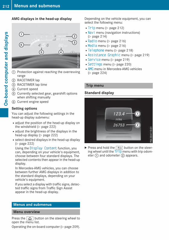
AMG displays in the head-up display
: Protection against reaching the overrevvingrange
; RACETIMER lap= RACETIMER lap time? Current speedA Currently selected gear, gearshift options
when shifting manuallyB Current engine speed
Setting optionsYou can adjust the following settings in thehead-up display submenu:Radjust the position of the head-up display onthe windshield (Y page 222)Radjust the brightness of the displays in thehead-up display (Y page 222)Rselect desired displays in the head-up display(Y page 222)Using the Display Content function, youcan, depending on your vehicle's equipment,choose between four standard displays. Theselected contents then appear in the head-updisplay.In Mercedes-AMG vehicles, you can choosebetween further AMG displays in addition tothe standard displays, depending on yourvehicle's equipment.If you select a display with traffic signs, detec-ted traffic signs from Traffic Sign Assistappear in the head-up display.
Menus and submenus
Menu overviewPress theò button on the steering wheel toopen the menu list.Operating the on-board computer (Y page 209).
Depending on the vehicle equipment, you canselect the following menu:RTrip menu (Y page 212)RNavi menu (navigation instructions)(Y page 214)RRadio menu (Y page 216)RMedia menu (Y page 216)RTelephone menu (Y page 218)RAssistance Graphic menu (Y page 219)RService menu (Y page 219)RSettings menu (Y page 220)RAMG menu in Mercedes-AMG vehicles(Y page 224)
Trip menu
Standard display
X Press and hold the% button on the steer-ing wheel until the Tripmenu with trip odom-eter: and odometer; appears.
212 Menus and submenusOn
-board
computerand
displays
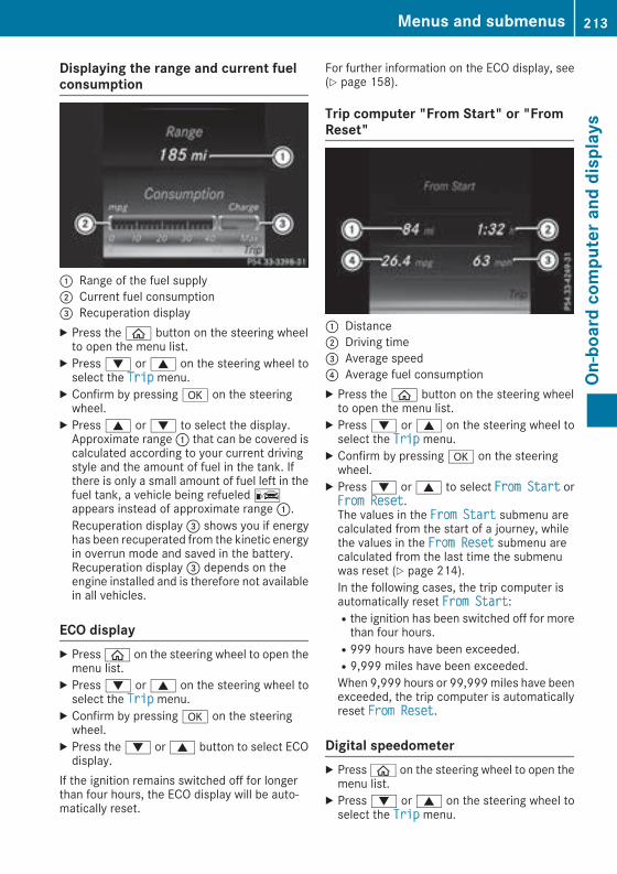
Displaying the range and current fuelconsumption
: Range of the fuel supply; Current fuel consumption= Recuperation displayX Press theò button on the steering wheelto open the menu list.
X Press: or9 on the steering wheel toselect the Trip menu.
X Confirm by pressinga on the steeringwheel.
X Press9 or: to select the display.Approximate range: that can be covered iscalculated according to your current drivingstyle and the amount of fuel in the tank. Ifthere is only a small amount of fuel left in thefuel tank, a vehicle being refueledCappears instead of approximate range:.Recuperation display= shows you if energyhas been recuperated from the kinetic energyin overrun mode and saved in the battery.Recuperation display= depends on theengine installed and is therefore not availablein all vehicles.
ECO displayX Pressò on the steering wheel to open themenu list.
X Press: or9 on the steering wheel toselect the Trip menu.
X Confirm by pressinga on the steeringwheel.
X Press the: or9 button to select ECOdisplay.
If the ignition remains switched off for longerthan four hours, the ECO display will be auto-matically reset.
For further information on the ECO display, see(Y page 158).
Trip computer "From Start" or "FromReset"
: Distance; Driving time= Average speed? Average fuel consumptionX Press theò button on the steering wheelto open the menu list.
X Press: or9 on the steering wheel toselect the Trip menu.
X Confirm by pressinga on the steeringwheel.
X Press: or9 to select From Start orFrom Reset.The values in the From Start submenu arecalculated from the start of a journey, whilethe values in the From Reset submenu arecalculated from the last time the submenuwas reset (Y page 214).In the following cases, the trip computer isautomatically reset From Start:Rthe ignition has been switched off for morethan four hours.R999 hours have been exceeded.R9,999 miles have been exceeded.When 9,999 hours or 99,999miles have beenexceeded, the trip computer is automaticallyreset From Reset.
Digital speedometerX Pressò on the steering wheel to open themenu list.
X Press: or9 on the steering wheel toselect the Trip menu.
Menus and submenus 213
On-board
computerand
displays
Z

X Confirm by pressinga on the steeringwheel.
X Press the: or9 button to select thedigital speedometer.
Resetting valuesX Press theò button on the steering wheelto open the menu list.
X Press: or9 on the steering wheel toselect the Trip menu.
X Confirm by pressinga on the steeringwheel.
X Press the: or9 button to select thefunction that you wish to reset.
X Pressa briefly.X Press: to select Yes and pressa toconfirm.You can reset the values of the following func-tions:RTrip odometerR"From Start" trip computerR"From Reset" trip computerRECO displayIf you reset the values in the ECO display, thevalues in the "From Start" trip computer arealso reset. If you reset the values in the "FromStart" trip computer, the values in the ECOdisplay are also reset.
Navigation system menu
Displaying navigation instructionsIn the Navi menu, the multifunction displayshows navigation instructions. You can find fur-ther information on navigation instructions inthe multimedia system in the Digital Operator'sManual.X Switch on the multimedia system.X Press theò button on the steering wheelto open the menu list.
X Press: or9 on the steering wheel toselect the Navi menu.
X Confirm by pressinga on the steeringwheel.
Route guidance not active
: Direction of travel; Current road
Route guidance active
No change of direction announced
: Distance to the next destination; Estimated arrival time= Distance to the next change of direction? Current road
214 Menus and submenusOn
-board
computerand
displays

Change of direction announced with alane recommendation
: Target of the change of direction; Distance to the change of direction= Change-of-direction symbol? Recommended lane and new lane during a
change of direction (white)A Possible laneB Lane not recommended (dark gray)On multilane roads, new lane recommendationscan be displayed for the next change of directionif the digital map supports this data. During thechange of direction, new lanes may be added.Lane not recommendedB: you will not be ableto complete the next change of direction if youstay in this lane.Possible laneA: you will only be able to com-plete the next change of direction in this lane.Recommended lane?: in this lane you will beable to complete the next change of directionand the one after that.
Change of direction without lane recom-mendation
: Road into which the change of directionleads
; Distance to change of direction and visualdistance display
= Change-of-direction symbolWhen a change of direction is to be made, youwill see symbol= for the change of directionand distance graphic;. The distance indicatorshortens towards the top of the display as youapproach the point of the announced change ofdirection. The change of direction starts oncethe distance display reaches zero.
Change of direction with lane recommen-dation
: Road into which the change of directionleads
; Distance to change of direction and visualdistance display
= Change-of-direction symbol? Lane recommendation
Menus and submenus 215
On-board
computerand
displays
Z

Other status indicators of the naviga-tion system
: Additional informationOther possible additional information:RNew Route... orCalculating Route...A new route is calculated.RRoad Not MappedThe vehicle position is inside the area of thedigitalmap but the road is not recognized, e.g.newly built streets, car parks or private land.RNo RouteNo route could be calculated to the selecteddestination.ROff MapThemap for the current vehicle position is notavailable.RO
You have reached the destination or an inter-mediate destination.
Radio menu
: Frequency band; Station frequency with memory position
= Name of artist? Name of trackThe multifunction display shows station; withstation frequency or station name. The presetposition is only displayed alongwith station; ifthis has been stored. You can store radio sta-tions in the multimedia system.X Switch on the multimedia system.X Press theò button on the steering wheelto open the menu list.
X Press: or9 on the steering wheel toselect the Radio menu.
X Confirm by pressinga on the steeringwheel.Currently set station; appears in the multi-function display.
X To open the station list: press: or9briefly.
X To select a station in the station list:press: or9 briefly.
X To select a station in the station list usingrapid scrolling: press and hold: or9.
X To select the waveband or station mem-ory: pressa briefly.
X Press: or9 to select thewaveband orstation memory.
X Pressa to confirm the selection.
i SIRIUS XM satellite radio functions like anormal radio.Further information about radio operation canbe found in the multimedia system in the Dig-ital Operator's Manual.
Media menu
Changing the media sourceYou can change the media source and playbackmode (audio or video) at any time in the Mediamenu.X Switch on the multimedia system.X Press theò button on the steering wheelto open the menu list.
X Press: or9 on the steering wheel toselect the Media menu.
216 Menus and submenusOn
-board
computerand
displays

X Confirm by pressinga on the steeringwheel.
X To open themedia sources list: pressabriefly.The list shows the following media sources,for example:RCD or DVD (DVD only in the COMAND mul-timedia system)RSD cardRMedia Register (only in the COMAND mul-timedia system)RUSB storage deviceRBluetooth® capable audio device
Please observe further information on mediasupport and media operation in the multimediasystem (see the Digital Operator's Manual).
Operating an audio player or audiomedia
: Media source, e.g. name of USB memorystick
; Current title= Name of artist? Name of albumA Folder nameAudio data from various audio devices or mediacan be played, depending on the equipmentinstalled in the vehicle.X Switch on the multimedia system.X Press theò button on the steering wheelto open the menu list.
X Press: or9 on the steering wheel toselect the Media menu.
X Confirm by pressinga on the steeringwheel.
X To select an audio player or media:pressa briefly. The list containing the mediasources appears.
X Press: or9 to select the correspond-ing audio player or media.
X Pressa to confirm.X To open the track list:press the: or9 button briefly.
X To select the next or previous track fromthe track list:press the: or9 buttonbriefly.
X To select a track from the track list usingrapid scrolling: press and hold: or9until the desired track is reached.If you press and hold the button, the speed ofrapid scroll increases after a short time. Notall audio drives or data carriers support thisfunction.
If the corresponding track information is storedon the audio player or media, the multifunctiondisplay shows the following:Rtrack numberRthe name of the trackRthe name of the artistRalbumThe track information does not appear in audioAUX mode (Auxiliary audio mode: externalaudio source connected).
Video DVD operation
X Switch on the multimedia system.X Press theò button on the steering wheelto open the menu list.
X Press: or9 on the steering wheel toselect the Media menu.
X Confirm by pressinga on the steeringwheel.
Menus and submenus 217
On-board
computerand
displays
Z
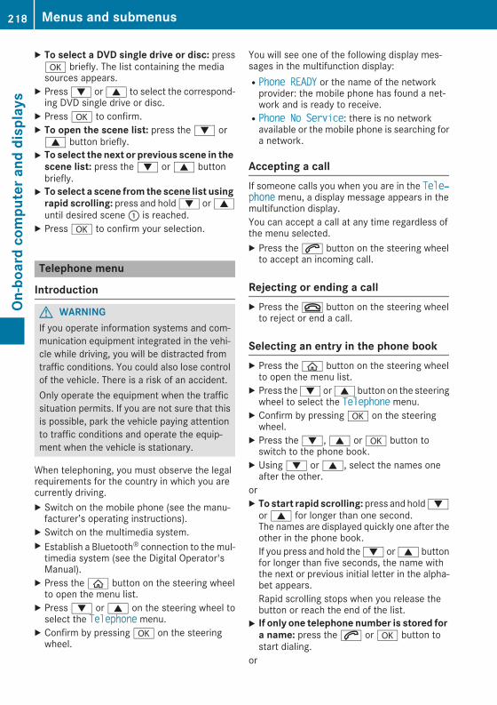
X To select a DVD single drive or disc: pressa briefly. The list containing the mediasources appears.
X Press: or9 to select the correspond-ing DVD single drive or disc.
X Pressa to confirm.X To open the scene list: press the: or9 button briefly.
X To select the next or previous scene in thescene list: press the: or9 buttonbriefly.
X To select a scene from the scene list usingrapid scrolling: press and hold: or9until desired scene: is reached.
X Pressa to confirm your selection.
Telephone menu
Introduction
G WARNINGIf you operate information systems and com-munication equipment integrated in the vehi-cle while driving, you will be distracted fromtraffic conditions. You could also lose controlof the vehicle. There is a risk of an accident.Only operate the equipment when the trafficsituation permits. If you are not sure that thisis possible, park the vehicle paying attentionto traffic conditions and operate the equip-ment when the vehicle is stationary.
When telephoning, you must observe the legalrequirements for the country in which you arecurrently driving.X Switch on the mobile phone (see the manu-facturer’s operating instructions).
X Switch on the multimedia system.X Establish a Bluetooth® connection to themul-timedia system (see the Digital Operator'sManual).
X Press theò button on the steering wheelto open the menu list.
X Press: or9 on the steering wheel toselect the Telephone menu.
X Confirm by pressinga on the steeringwheel.
You will see one of the following display mes-sages in the multifunction display:RPhone READY or the name of the networkprovider: the mobile phone has found a net-work and is ready to receive.RPhone No Service: there is no networkavailable or the mobile phone is searching fora network.
Accepting a callIf someone calls you when you are in the Tele‐phone menu, a display message appears in themultifunction display.You can accept a call at any time regardless ofthe menu selected.X Press the6 button on the steering wheelto accept an incoming call.
Rejecting or ending a callX Press the~ button on the steering wheelto reject or end a call.
Selecting an entry in the phone bookX Press theò button on the steering wheelto open the menu list.
X Press the: or9 button on the steeringwheel to select the Telephone menu.
X Confirm by pressinga on the steeringwheel.
X Press the:,9 ora button toswitch to the phone book.
X Using: or9, select the names oneafter the other.
orX To start rapid scrolling: press and hold:or9 for longer than one second.The names are displayed quickly one after theother in the phone book.If you press and hold the: or9 buttonfor longer than five seconds, the name withthe next or previous initial letter in the alpha-bet appears.Rapid scrolling stops when you release thebutton or reach the end of the list.
X If only one telephone number is stored fora name: press the6 ora button tostart dialing.
or
218 Menus and submenusOn
-board
computerand
displays

X If there is more than one number for aparticular name: press the6 orabutton to display the numbers.
X Press the: or9 button to select thenumber you want to dial.
X Press the6 orabutton to start dialing.orX To exit the telephone book: press the~or% button briefly.
RedialingThe on-board computer saves the last names ornumbers dialed in the redial memory.X Press theò button on the steering wheelto open the menu list.
X Press the: or9 button on the steeringwheel to select the Telephone menu.
X Confirm by pressinga on the steeringwheel.
X Press the6 button to switch to the redialmemory.
X Press the: or9 button to select thedesired name or number.
X Press the6 orabutton to start dialing.orX To exit the redial memory: press the~or% button briefly.
Assistance graphic menu
X Press theò button on the steering wheelto open the menu list.
X Press the: or9 button on the steeringwheel to select the Assistance Graphicmenu.
X Confirm by pressinga on the steeringwheel.The assistance graphic displays the status ofand information from the following drivingsystems or driving safety systems:RDistance display of DISTRONIC PLUS(Y page 168)RTraffic Sign Assist (Y page 193)RDistance warning and the autonomousbraking function COLLISION PREVENTIONASSIST PLUS (Y page 67)RPRE-SAFE® Brake (Y page 73)RBlind Spot Assist (Y page 193) or ActiveBlind Spot Assist (Y page 197)RATTENTION ASSIST (Y page 192)RLane Keeping Assist (Y page 195) or ActiveLane Keeping Assist (Y page 200)RRear window wiper (Y page 120)
X Press: to display the ATTENTION ASSISTassessment.
Service menu
IntroductionDepending on the equipment installed in thevehicle, you have the following options in theService menu:Rcalling up displaymessages inmessagemem-ory (Y page 227)Rrestarting the tire pressure loss warning sys-tem (Canada only) (Y page 343).Rchecking the tire pressure electronically(Y page 345).Rcalling up the service due date (Y page 310).Rdisplaying the DEF level and range(Y page 219).
Displaying the DEF level and rangeX Press theò button on the steering wheelto open the menu list.
X Press: or9 on the steering wheel toselect the Service menu.
X Confirm by pressinga on the steeringwheel.
Menus and submenus 219
On-board
computerand
displays
Z
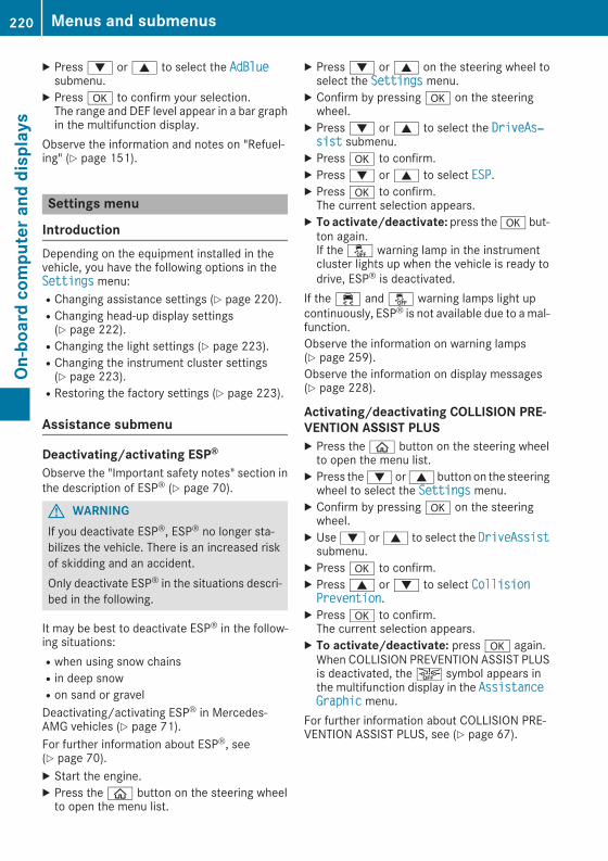
X Press: or9 to select the AdBluesubmenu.
X Pressa to confirm your selection.The range and DEF level appear in a bar graphin the multifunction display.
Observe the information and notes on "Refuel-ing" (Y page 151).
Settings menu
IntroductionDepending on the equipment installed in thevehicle, you have the following options in theSettings menu:RChanging assistance settings (Y page 220).RChanging head-up display settings(Y page 222).RChanging the light settings (Y page 223).RChanging the instrument cluster settings(Y page 223).RRestoring the factory settings (Y page 223).
Assistance submenu
Deactivating/activating ESP®Observe the "Important safety notes" section inthe description of ESP® (Y page 70).
G WARNINGIf you deactivate ESP®, ESP® no longer sta-bilizes the vehicle. There is an increased riskof skidding and an accident.Only deactivate ESP® in the situations descri-bed in the following.
It may be best to deactivate ESP® in the follow-ing situations:Rwhen using snow chainsRin deep snowRon sand or gravelDeactivating/activating ESP® in Mercedes-AMG vehicles (Y page 71).For further information about ESP®, see(Y page 70).X Start the engine.X Press theò button on the steering wheelto open the menu list.
X Press: or9 on the steering wheel toselect the Settings menu.
X Confirm by pressinga on the steeringwheel.
X Press: or9 to select the DriveAs‐sist submenu.X Pressa to confirm.X Press: or9 to select ESP.X Pressa to confirm.The current selection appears.
X To activate/deactivate: press thea but-ton again.If the å warning lamp in the instrumentcluster lights up when the vehicle is ready todrive, ESP® is deactivated.
If the ÷ and å warning lamps light upcontinuously, ESP® is not available due to amal-function.Observe the information on warning lamps(Y page 259).Observe the information on display messages(Y page 228).
Activating/deactivating COLLISION PRE-VENTION ASSIST PLUSX Press theò button on the steering wheelto open the menu list.
X Press the: or9 button on the steeringwheel to select the Settings menu.
X Confirm by pressinga on the steeringwheel.
X Use: or9 to select the DriveAssistsubmenu.
X Pressa to confirm.X Press9 or: to select CollisionPrevention.X Pressa to confirm.The current selection appears.
X To activate/deactivate: pressa again.When COLLISION PREVENTION ASSIST PLUSis deactivated, theæ symbol appears inthe multifunction display in the AssistanceGraphic menu.
For further information about COLLISION PRE-VENTION ASSIST PLUS, see (Y page 67).
220 Menus and submenusOn
-board
computerand
displays

Activating/deactivating PRE-SAFE®BrakePRE‑SAFE® Brake is only available for vehicleswith the Driving Assistance package.X Press theò button on the steering wheelto open the menu list.
X Press the: or9 button on the steeringwheel to select the Settings menu.
X Confirm by pressinga on the steeringwheel.
X Use: or9 to select the DriveAssistsubmenu.
X Pressa to confirm.X Press: or9 to select PRE-SAFEBrake.X Pressa to confirm.The current selection appears.
X To activate/deactivate: press thea but-ton again.When PRE-SAFE® Brake is deactivated, theæ symbol appears in themultifunction dis-play in the Assistance Graphic menu.
For more information on PRE‑SAFE® Brake, see(Y page 73).
Activating/deactivating Blind Spot AssistX Press theò button on the steering wheelto open the menu list.
X Press: or9 on the steering wheel toselect the Settings menu.
X Confirm by pressinga on the steeringwheel.
X Press: or9 to select the DriveAs‐sist submenu.X Pressa to confirm.X Press: or9 to select Blind SpotAssist.X Pressa to confirm.The current selection appears.
X To activate/deactivate: press thea but-ton again.
For further information about Blind Spot Assist,see (Y page 193).For further information about Active Blind SpotAssist, see (Y page 197).
Setting ATTENTION ASSISTX Press theò button on the steering wheelto open the menu list.
X Press the: or9 button on the steeringwheel to select the Settings menu.
X Confirm by pressinga on the steeringwheel.
X Use: or9 to select the DriveAssistsubmenu.
X Pressa to confirm.X Press: or9 to select ATTENTIONASSIST.X Pressa to confirm.X Press: or9 to select Off, Standardor Sensitive.
X Press thea button to confirm the selec-tion.When ATTENTION ASSIST is deactivated, theé symbol appears in the AssistanceGraphic menu in the multifunction display.
For further information about ATTENTIONASSIST, see (Y page 191).
Setting Lane Keeping AssistX Press theò button on the steering wheelto open the menu list.
X Press: or9 on the steering wheel toselect the Settings menu.
X Confirm by pressinga on the steeringwheel.
X Press: or9 to select the DriveAs‐sist submenu.X Pressa to confirm.X Press: or9 to select Lane KeepingAssist.X Pressa to confirm.The current selection Standard or Adaptiveappears.
X To change the setting: pressa again.For further information about Lane KeepingAssist, see (Y page 195).For further information about Active Lane Keep-ing Assist, see (Y page 200).
Menus and submenus 221
On-board
computerand
displays
Z

Head-up display submenu
Selecting other displays
: Vehicle speed display; Vehicle speed and navigation instruction
display= Vehicle speed display and Traffic Sign AssistUsing the Display Content function, you canchoose from up to four display options depend-ing on the vehicle's equipment. The selectedcontents appear in the Head-up Display.InMercedes-AMG vehicles, you can also choosebetween two AMG displays. If you select anAMG display, the head-up display shows AMG-specific contents.If you select a displaywith traffic signs, detectedtraffic signs from Traffic Sign Assist appear inthe head-up display.X Press theò button on the steering wheelto open the menu list.
X Press: or9 on the steering wheel toselect the Settings menu.
X Confirm by pressinga on the steeringwheel.
X Press: or9 to select the Head-upDisplay submenu.X Pressa to confirm.X Press: or9 to select Display Con‐tent.X Pressa to confirm.A graphic selection list appears.
X Press: or9 to select the desired dis-play.
X Press thea button to confirm the selec-tion.
You can findmore information on the navigationdisplays in the multimedia system (see DigitalOperator's Manual).
Information on displays of Traffic Sign Assist(Y page 192).
Setting the positionYou can adjust the position of the Head-up Dis-play on the windshield. You can compensate forheight differences if the seat positions arechanged, for example.X Switch on the Head-up Display (Y page 211).X Press theò button on the steering wheelto open the menu list.
X Press the: or9 button on the steeringwheel to select the Settings menu.
X Confirm by pressinga on the steeringwheel.
X Use: or9 to select the Head-upDisplay submenu.X Pressa to confirm.X Press: or9 to select the Positionfunction.
X Press thea button to save the setting.X Press: or9 to adjust the position to alevel from Level +5 (up) to Level -5 (down).
X Press thea or% button to save thesetting.
Using the Memory function, you can save andcall up the set position of theHead-upDisplay asa single memory preset (Y page 109).
Setting the brightnessThe brightness of the Head-up Display is auto-matically adjusted to the surrounding ambientlight. You can also individually adjust the bright-ness of the Head-up Display.X Switch on the Head-up Display (Y page 211).X Press theò button on the steering wheelto open the menu list.
X Press the: or9 button on the steeringwheel to select the Settings menu.
X Confirm by pressinga on the steeringwheel.
X Use: or9 to select the Head-upDisplay submenu.X Pressa to confirm.X Press: or9 to select the Brightnessfunction.
X Press thea button to save the setting.
222 Menus and submenusOn
-board
computerand
displays

X Press the: or9 button to adjust thebrightness to a level from Level +5 (bright) toLevel -5 (dark).
X Press thea or% button to save thesetting.
Light submenu
Switching the daytime running lamps on/offThis function is not available in Canada.X Pressò on the steering wheel to open themenu list.
X Press: or9 on the steering wheel toselect the Settings menu.
X Confirm by pressinga on the steeringwheel.
X Press: or9 to select the Lightssubmenu.
X Pressa to confirm.X Using: or9, select the DaytimeRunning Lights function.If the Daytime Running Lights function hasbeen switched on, the multifunction displayshows the cone of light and theW symbolin yellow.
X Press thea button to save the setting.Further information on daytime runninglampsDaytime Running Lights (Y page 111).
Instrument cluster submenu
Selecting the distance unitThe Display Unit Speed-/Odometer functionallows you to choose whether certain displaysappear in kilometers or miles in the multifunc-tion display.X Press theò button on the steering wheelto open the menu list.
X Press the: or9 button on the steeringwheel to select the Settings menu.
X Confirm by pressinga on the steeringwheel.
X Use: or9 to select the InstrumentCluster submenu.X Pressa to confirm.
X Press: or9 to select the DisplayUnit Speed-/Odometer function.The current setting km or Miles appears.
X Press thea button to save the setting.The selected unit of measurement for distanceapplies to:RDigital speedometer in the Trip menuROdometer and the trip odometerRTrip computerRCurrent consumption and the rangeRNavigation instructions in the Navi menuRCruise controlRDISTRONIC PLUS with Steering Assist andStop&Go PilotRASSYST PLUS service interval display
Switching the additional speedometeron/offIf the additional speedometer is switched on,the speed is shown in the status bar in the mul-tifunction display instead of the outside tem-perature.The speed display is inverse to the speedome-ter.X Press theò button on the steering wheelto open the menu list.
X Press the: or9 button on the steeringwheel to select the Settings menu.
X Confirm by pressinga on the steeringwheel.
X Use: or9 to select the InstrumentCluster submenu.X Pressa to confirm.X Using: or9, select the AdditionalSpeedometer [km/h] function.The current selection appears.
X To activate/deactivate: press thea but-ton again.
Restoring the factory settingsX Press theò button on the steering wheelto open the menu list.
X Press the: or9 button on the steeringwheel to select the Settings menu.
X Confirm by pressinga on the steeringwheel.
X Use: or9 to select the FactorySettings submenu.
Menus and submenus 223
On-board
computerand
displays
Z

X Pressa to confirm.The Reset All Settings? functionappears.
X Press: or9 to select No or Yes.X Pressa to confirm the selection.If you have selected Yes, the multifunctiondisplay shows a confirmation message.
For safety reasons, the Daytime RunningLights function in the Lights submenu is onlyreset when the vehicle is stationary.
AMG menu (Mercedes-AMG vehicles)
Warm-up
: Digital speedometer; Gear indicator= Charge-air pressure? Engine oil temperatureA Transmission oil temperatureX Press theò button on the steering wheelto open the menu list.
X Press the: or9 button on the steeringwheel to select the AMG menu.
X Confirm by pressinga on the steeringwheel.Engine and transmission oil tempera-tures: when the engine and transmission areat normal operating temperature, oil temper-atures? andA are displayed in white in themultifunction display.If the multifunction display shows oil temper-ature? orA in blue, the engine or thetransmission are not yet at normal operatingtemperature. Avoid driving at full engine out-put during this time.
G-Meter
While the vehicle is in motion, the G-Metershows the forces that are exerted on the driverboth laterally and in the direction of travel.The maximum values are indicated in red in theguideline system.X Pressò on the steering wheel to open themenu list.
X Press the: or9 button on the steeringwheel to select the AMG menu.
X Confirm by pressinga on the steeringwheel.
X Press the9 button repeatedly until the G-Meter appears.The maximum values of the G-Meter aresaved.
X To reset the G-Meter: pressa again.X Using: or9 select Yes on the steer-ing wheel.
X Pressa to confirm.The maximum values of the G-Meter aredeleted.
If the ignition remains switched off for longerthan four hours, the G-Meter will be automati-cally reset.
224 Menus and submenusOn
-board
computerand
displays

SETUP
Overview
: Drive Eco/Comfort/Sport/Sport +/Man‐ual; Chassis Comfort/Sport/Sport += Steering Comfort/Sport? ECO Start/Stop Active/Inactive/OffA ESP® On/Off or SPORT handling modeSportSETUP shows the following functions and set-tings:Rthe gear indicatorRthe digital speedometerRthe drive system settingRthe suspension modeRthe steering settingRthe setting of the ECO start/stop functionRthe ESP® (Electronic Stability Program) status
Select SETUPX Useò on the steering wheel to call up thelist of menus.
X Press the: or9 button on the steeringwheel to select the AMG menu.
X Confirm by pressinga on the steeringwheel.
X Press9 repeatedly until SETUP appears.
RACETIMER
Displaying and starting RACETIMER
: Lap; RACETIMERThe RACETIMER is only intended for use on aclosed race circuit. Do not use the function onpublic roads.You can start theRACETIMERwhen the engine isrunning or the ignition is switched on.X Useò on the steering wheel to call up thelist of menus.
X Press the: or9 button on the steeringwheel to select the AMG menu.
X Confirm by pressinga on the steeringwheel.
X Press: or9 repeatedly until theRACETIMER appears.
X To start: press thea button to start theRACETIMER.
Starting a new lap
: Lap; RACETIMER= Quickest lap time
Menus and submenus 225
On-board
computerand
displays
Z
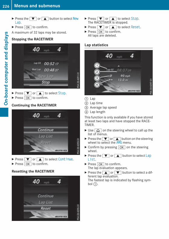
X Press the: or9 button to select NewLap.X Pressa to confirm.A maximum of 32 laps may be stored.
Stopping the RACETIMER
X Press: or9 to select Stop.X Pressa to confirm.
Continuing the RACETIMER
X Press: or9 to select Continue.X Pressa to confirm.
Resetting the RACETIMER
X Press: or9 to select Stop.The RACETIMER is stopped.
X Press: or9 to select Reset.X Pressa to confirm.All laps are deleted.
Lap statistics
: Lap; Lap time= Average lap speed? Lap lengthThis function is only available if you have storedat least two laps and have stopped the RACE-TIMER.X Useò on the steering wheel to call up thelist of menus.
X Press the: or9 button on the steeringwheel to select the AMG menu.
X Confirm by pressinga on the steeringwheel.
X Press the: or9 button to select LapList.X Pressa to confirm.The lap evaluation appears.
X Press the9 or: button to select a dif-ferent lap evaluation.The fastest lap is indicated by flashing sym-bol:.
226 Menus and submenusOn
-board
computerand
displays

Display messages
Introduction
General notesDisplay messages appear in the multifunction display.Display messages with graphic displays may be shown in simplified form in the Operator's Manualand may therefore differ from the multifunction display.Please respond in accordance with the display messages and follow the additional notes in thisOperator's Manual.With certain display messages, you will also hear a warning tone.You can hide the display messages. The display messages are then stored in the message memory.Rectify the cause of a display message as soon as possible.When you stop and park the vehicle, please observe the notes on:RHOLD function (Y page 171)RParking (Y page 154)
Hiding display messagesX Press thea or% button on the steering wheel.The multifunction display hides the display message.
High-priority display messages are shown in red in the multifunction display. Some high-prioritydisplay messages cannot be hidden.The multifunction display shows these messages continuously until the causes for the messageshave been remedied.
Message memoryThe on-board computer saves certain display messages in themessage memory. You can call upthe display messages:X Press theò button on the steering wheel to open the menu list.X Press: or9 on the steering wheel to select the Service menu.X Confirm by pressinga on the steering wheel.X Press the: or9 button to select the message memory.If there are no display messages, the No Messages display appears in the multifunction display.When there are display messages, the number of stored messages appears.
X Pressa to confirm.X Press the: or9 button to scroll through the display messages.
Display messages 227
On-board
computerand
displays
Z

Safety systems
Display messages Possible causes/consequences andM Solutions
!÷Currently Unavaila‐ble See Operator'sManual
ABS (Anti-lock Braking System) and ESP® (Electronic Stability Pro-gram) are temporarily not available.Other driving systems and driving safety systems may also malfunc-tion.In addition, the ÷ and ! warning lamps light up in the instru-ment cluster.For example, the on-board voltage may be insufficient.
G WARNINGThe brake system continues to function normally, but without thefunctions listed above. The wheels could therefore lock if you brakehard, for example.The steerability and braking characteristics may be severely affected.The braking distance in an emergency braking situation can increase.If ESP® is not operational, ESP® is unable to stabilize the vehicle.There is an increased risk of skidding and an accident.X Drive on carefully.Carefully drive a suitable distance, making slight steering move-ments at a speed above 12 mph (20 km/h).If the display message disappears, the functions mentioned aboveare available again.
If the multifunction display still shows the display message:X Drive on carefully.X Visit a qualified specialist workshop immediately.
!÷Inoperative SeeOperator's Manual
ABS and ESP® are malfunctioning.Other driving systems and driving safety systems may also malfunc-tion.The$ (USA only) orJ (Canada only), ÷ and ! warninglamps in the instrument cluster may also light up.
G WARNINGThe brake system continues to function normally, but without thefunctions listed above. The wheels could therefore lock if you brakehard, for example.The steerability and braking characteristics may be severely affected.The braking distance in an emergency braking situation can increase.If ESP® is not operational, ESP® is unable to stabilize the vehicle.There is an increased risk of skidding and an accident.X Drive on carefully.X Visit a qualified specialist workshop immediately.
228 Display messagesOn
-board
computerand
displays

Display messages Possible causes/consequences andM Solutions
÷Inoperative SeeOperator's Manual
ESP® is malfunctioning.Other driving systems and driving safety systems may also malfunc-tion.The ÷ warning lamp also lights up in the instrument cluster.
G WARNINGThe brake system continues to function normally, but without thefunctions listed above.The braking distance in an emergency braking situation can thusincrease.If ESP® is not operational, ESP® is unable to stabilize the vehicle.There is an increased risk of skidding and an accident.X Drive on carefully.X Visit a qualified specialist workshop immediately.
÷Currently Unavaila‐ble See Operator'sManual
ESP® is temporarily unavailable.Other driving systems and driving safety systems may also malfunc-tion.The ÷ warning lamp also lights up in the instrument cluster.The self-diagnosis function might not be complete, for example.
G WARNINGThe brake system continues to function normally, but without thefunctions listed above. The wheels could therefore lock if you brakehard, for example.The braking distance in an emergency braking situation can thusincrease.If ESP® is not operational, ESP® is unable to stabilize the vehicle.There is an increased risk of skidding and an accident.X Carefully drive a suitable distance, making slight steering move-ments at a speed above 12 mph (20 km/h).If the display message disappears, the functions mentioned aboveare available again.
If the multifunction display still shows the display message:X Drive on carefully.X Visit a qualified specialist workshop immediately.
Display messages 229
On-board
computerand
displays
Z
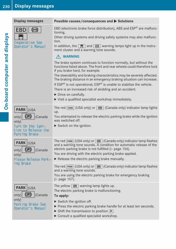
Display messages Possible causes/consequences andM Solutions
T!÷Inoperative SeeOperator's Manual
EBD (electronic brake force distribution), ABS and ESP® are malfunc-tioning.Other driving systems and driving safety systems may also malfunc-tion.In addition, the ÷ and ! warning lamps light up in the instru-ment cluster and a warning tone sounds.
G WARNINGThe brake system continues to function normally, but without thefunctions listed above. The front and rear wheels could therefore lockif you brake hard, for example.The steerability and braking characteristics may be severely affected.The braking distance in an emergency braking situation can increase.If ESP® is not operational, ESP® is unable to stabilize the vehicle.There is an increased risk of skidding and an accident.X Drive on carefully.X Visit a qualified specialist workshop immediately.
F(USA
only)!(Canadaonly)Turn On the Igni‐tion to Release theParking Brake
The redF (USA only) or! (Canada only) indicator lamp lightsup.You attempted to release the electric parking brake while the ignitionwas switched off.X Switch on the ignition.
F(USA
only)!(Canadaonly)Please Release Park‐ing Brake
The redF (USA only) or! (Canada only) indicator lamp flashesand a warning tone sounds. A condition for automatic release of theelectric parking brake is not fulfilled (Y page 156).You are driving with the electric parking brake applied.X Release the electric parking brake manually.
The redF (USA only) or! (Canada only) indicator lamp flashesand a warning tone sounds.You are using the electric parking brake for emergency braking(Y page 157).
F(USA
only)!(Canadaonly)Parking Brake SeeOperator's Manual
The yellow! warning lamp lights up.The electric parking brake is malfunctioning.To apply:X Switch the ignition off.X Press the electric parking brake handle for at least ten seconds.X Shift the transmission to positionj.X Consult a qualified specialist workshop.
230 Display messagesOn
-board
computerand
displays

Display messages Possible causes/consequences andM Solutions
The yellow! warning lamp and the redF (USA only) or!(Canada only) indicator lamp light up.The electric parking brake is malfunctioning.To release:X Switch off the ignition and turn it back on.X Release the electric parking brake manually.orX Release the electric parking brake automatically (Y page 156).If the electric parking brake still cannot be released:X Do not drive on.X Consult a qualified specialist workshop.
The redF (USA only) or! (Canada only) indicator lamp flashesand the yellow! warning lamp lights up.The electric parking brake is malfunctioning.To release:X Switch off the ignition and turn it back on.X Release the electric parking brake manually.To apply:X Switch off the ignition and turn it back on.X Apply the electric parking brake manually.If the redF (USA only) or! (Canada only) indicator lamp con-tinues to flash:X Do not drive on.X Secure the vehicle against rolling away (Y page 357).X Shift the transmission to positionj.X Turn the front wheels towards the curb.X Consult a qualified specialist workshop.
Display messages 231
On-board
computerand
displays
Z

Display messages Possible causes/consequences andM Solutions
The yellow! warning lamp lights up. The redF (USA only)or! (Canada only) indicator lamp flashes for about ten secondsafter the electric parking brake has been applied or released. It thengoes out or remains lit.The electric parking brake is malfunctioning.X Switch off the ignition and turn it back on.X Apply the electric parking brake.If it is not possible to engage the electric parking brake:X Shift the transmission to positionj.X Visit a qualified specialist workshop.If it is not possible to release the electric parking brake manually:X Release the electric parking brake automatically (Y page 156).If the electric parking brake still cannot be released:X Consult a qualified specialist workshop.
The yellow! warning lamp lights up. If you manually apply orrelease the electric parking brake, the redF (USA only) or!(Canada only) indicator lamp flashes.The electric parking brake is malfunctioning. It is not possible to applythe electric parking brake manually.X Shift the transmission to positionj, as the electric parking brakeis not applied automatically.
X Visit a qualified specialist workshop.If it is not possible to release the electric parking brake manually:X Release the electric parking brake automatically (Y page 156).
F(USA
only)!(Canadaonly)Parking Brake Inop‐erative
The yellow! warning lamp lights up. The redF (USA only)or! (Canada only) indicator lamp flashes for about ten secondsafter the electric parking brake has been applied or released. It thengoes out or remains lit.The electric parking brake is malfunctioning, e.g. because of over-voltage or undervoltage.X Remove the cause for the overvoltage or undervoltage, e.g. bycharging the battery or restarting the engine.
X Engage or release the electric parking brake.If it remains impossible to apply or release the electric parking brake:X Switch off the ignition and turn it back on.X Engage or release the electric parking brake.If the electric parking brake still cannot be released:X Consult a qualified specialist workshop.If the electric parking brake still cannot be applied:X Visit a qualified specialist workshop.
232 Display messagesOn
-board
computerand
displays

Display messages Possible causes/consequences andM Solutions
The yellow! warning lamp lights up and the redF (USA only)or! (Canada only) indicator lamp flashes.It is not possible to apply the electric parking brake manually.X Shift the transmission to positionj.X Visit a qualified specialist workshop.
$(USA
only)J(Canadaonly)Check Brake FluidLevel
There is not enough brake fluid in the brake fluid reservoir.In addition, the$ (USA only) orJ (Canada only) warning lamplights up in the instrument cluster and a warning tone sounds.
G WARNINGThe braking effect may be impaired.There is a risk of an accident.X Pull over and stop the vehicle safely as soon as possible, payingattention to road and traffic conditions. Do not continue drivingunder any circumstances.
X Secure the vehicle against rolling away (Y page 154).X Consult a qualified specialist workshop.X Do not add brake fluid. This does not correct the malfunction.
#Check Brake Pad Wear
The brake pads/linings have reached their wear limit.USA only: the$ red brake system warning lamp is lit while theengine is running.X Visit a qualified specialist workshop.
GInoperative
One or more main features of the mbrace system are malfunctioning.X Visit a qualified specialist workshop.
Collision Preven‐tion Assist PlusCurrently Unavaila‐ble See Operator'sManual
COLLISION PREVENTIONASSIST PLUS is temporarily not operational.Possible causes are:Rthe radar sensor system is temporarily inoperative, e.g. due to elec-tromagnetic radiation emitted by nearby TV or radio stations orother sources of electromagnetic radiationRthe system is outside the operating temperature rangeRthe on-board voltage is too lowWhen the causes stated above no longer apply, the display messagedisappears.COLLISION PREVENTION ASSIST PLUS is operational again.If the display message does not disappear:X Pull over and stop the vehicle safely as soon as possible, payingattention to road and traffic conditions.
X Secure the vehicle against rolling away (Y page 154).X Restart the engine.
Display messages 233
On-board
computerand
displays
Z
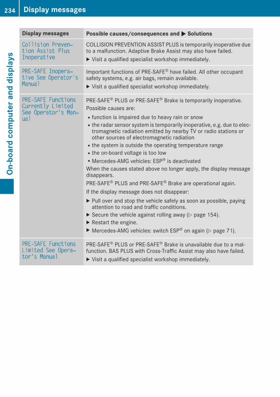
Display messages Possible causes/consequences andM Solutions
Collision Preven‐tion Assist PlusInoperativeCOLLISION PREVENTION ASSIST PLUS is temporarily inoperative dueto a malfunction. Adaptive Brake Assist may also have failed.X Visit a qualified specialist workshop immediately.
PRE-SAFE Inopera‐tive See Operator'sManualImportant functions of PRE-SAFE® have failed. All other occupantsafety systems, e.g. air bags, remain available.X Visit a qualified specialist workshop immediately.
PRE-SAFE FunctionsCurrently LimitedSee Operator's Man‐ual
PRE‑SAFE® PLUS or PRE‑SAFE® Brake is temporarily inoperative.Possible causes are:Rfunction is impaired due to heavy rain or snowRthe radar sensor system is temporarily inoperative, e.g. due to elec-tromagnetic radiation emitted by nearby TV or radio stations orother sources of electromagnetic radiationRthe system is outside the operating temperature rangeRthe on-board voltage is too lowRMercedes-AMG vehicles: ESP® is deactivatedWhen the causes stated above no longer apply, the display messagedisappears.PRE‑SAFE® PLUS and PRE‑SAFE® Brake are operational again.If the display message does not disappear:X Pull over and stop the vehicle safely as soon as possible, payingattention to road and traffic conditions.
X Secure the vehicle against rolling away (Y page 154).X Restart the engine.X Mercedes-AMG vehicles: switch ESP® on again (Y page 71).
PRE-SAFE FunctionsLimited See Opera‐tor's ManualPRE‑SAFE® PLUS or PRE‑SAFE® Brake is unavailable due to a mal-function. BAS PLUS with Cross-Traffic Assist may also have failed.X Visit a qualified specialist workshop immediately.
234 Display messagesOn
-board
computerand
displays
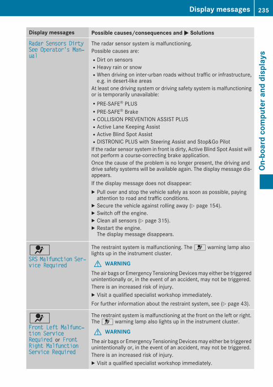
Display messages Possible causes/consequences andM Solutions
Radar Sensors DirtySee Operator's Man‐ualThe radar sensor system is malfunctioning.Possible causes are:RDirt on sensorsRHeavy rain or snowRWhen driving on inter-urban roads without traffic or infrastructure,e.g. in desert-like areas
At least one driving system or driving safety system is malfunctioningor is temporarily unavailable:RPRE-SAFE® PLUSRPRE-SAFE® BrakeRCOLLISION PREVENTION ASSIST PLUSRActive Lane Keeping AssistRActive Blind Spot AssistRDISTRONIC PLUS with Steering Assist and Stop&Go PilotIf the radar sensor system in front is dirty, Active Blind Spot Assist willnot perform a course-correcting brake application.Once the cause of the problem is no longer present, the driving anddrive safety systems will be available again. The display message dis-appears.If the display message does not disappear:X Pull over and stop the vehicle safely as soon as possible, payingattention to road and traffic conditions.
X Secure the vehicle against rolling away (Y page 154).X Switch off the engine.X Clean all sensors (Y page 315).X Restart the engine.The display message disappears.
6SRS Malfunction Ser‐vice Required
The restraint system is malfunctioning. The 6 warning lamp alsolights up in the instrument cluster.
G WARNINGThe air bags or Emergency Tensioning Devicesmay either be triggeredunintentionally or, in the event of an accident, may not be triggered.There is an increased risk of injury.X Visit a qualified specialist workshop immediately.For further information about the restraint system, see (Y page 43).
6Front Left Malfunc‐tion ServiceRequired or FrontRight MalfunctionService Required
The restraint system is malfunctioning at the front on the left or right.The 6 warning lamp also lights up in the instrument cluster.
G WARNINGThe air bags or Emergency Tensioning Devicesmay either be triggeredunintentionally or, in the event of an accident, may not be triggered.There is an increased risk of injury.X Visit a qualified specialist workshop immediately.
Display messages 235
On-board
computerand
displays
Z
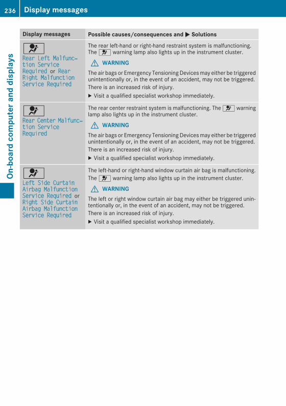
Display messages Possible causes/consequences andM Solutions
6Rear Left Malfunc‐tion ServiceRequired or RearRight MalfunctionService Required
The rear left-hand or right-hand restraint system is malfunctioning.The 6 warning lamp also lights up in the instrument cluster.
G WARNINGThe air bags or Emergency Tensioning Devicesmay either be triggeredunintentionally or, in the event of an accident, may not be triggered.There is an increased risk of injury.X Visit a qualified specialist workshop immediately.
6Rear Center Malfunc‐tion ServiceRequired
The rear center restraint system is malfunctioning. The 6 warninglamp also lights up in the instrument cluster.
G WARNINGThe air bags or Emergency Tensioning Devicesmay either be triggeredunintentionally or, in the event of an accident, may not be triggered.There is an increased risk of injury.X Visit a qualified specialist workshop immediately.
6Left Side CurtainAirbag MalfunctionService Required orRight Side CurtainAirbag MalfunctionService Required
The left-hand or right-hand window curtain air bag is malfunctioning.The 6 warning lamp also lights up in the instrument cluster.
G WARNINGThe left or right window curtain air bag may either be triggered unin-tentionally or, in the event of an accident, may not be triggered.There is an increased risk of injury.X Visit a qualified specialist workshop immediately.
236 Display messagesOn
-board
computerand
displays

Display messages Possible causes/consequences andM Solutions
Front Passenger Air‐bag Disabled SeeOperator's ManualThe front-passenger front air bag is deactivated during the journey,even though:Ran adultorRa person of the corresponding stature is on the front-passenger seatIf additional forces are applied to the seat, the system may interpretthe occupant's weight as lower than it actually is.
G WARNINGThe front-passenger air bag does not deploy during an accident.There is an increased risk of injury.X Pull over and stop the vehicle safely as soon as possible, payingattention to road and traffic conditions.
X Secure the vehicle against rolling away (Y page 154).X Switch the ignition off.X Have the occupant get out of the vehicle.X Keep the seat unoccupied, close the front-passenger door andswitch on the ignition.
X Observe the PASSENGER AIR BAG indicator lamps in the centerconsole and the multifunction display and check the following:Seat unoccupied and ignition switched on:Ra self-diagnosis is carried out. The PASSENGER AIR BAG OFF andPASSENGER AIR BAG ON indicator lamps must light up simulta-neously for approximately six secondsRthe PASSENGER AIR BAG OFF indicator lamp must then light upand remain lit after the self-diagnosis. If the indicator lamp is on,OCS (Occupant Classification System) has disabled the front-passenger front air bag (Y page 51)Rthe display messages Front Passenger Airbag EnabledSee Operator's Manual or Front Passenger Airbag Dis‐abled See Operator's Manual must not appear in the multi-function display
X Wait for a period of at least 60 seconds until the necessary systemchecks have been completed.
X Make sure that the display messages do not appear in the multi-function display.
If these conditions are fulfilled, the front-passenger seat can be occu-pied again. Whether the PASSENGER AIR BAG OFF indicator lampremains lit or goes out depends on how OCS classifies the occupant.If the conditions are not fulfilled, the system is not operating correctly.X Visit a qualified specialist workshop immediately.For further information about theOccupant Classification System, see(Y page 51).
Display messages 237
On-board
computerand
displays
Z

Display messages Possible causes/consequences andM Solutions
Front Passenger Air‐bag Enabled SeeOperator's ManualThe front-passenger front air bag is enabled during the journey, eventhough:Ra child, a small adult or an object weighing less than the system'sweight threshold is located on the front-passenger seatorRthe front-passenger seat is unoccupiedThe systemmay detect objects or forces applying additional weight onthe seat.
G WARNINGThe front-passenger front air bag may deploy unintentionally.There is an increased risk of injury.X Pull over and stop the vehicle safely as soon as possible, payingattention to road and traffic conditions.
X Secure the vehicle against rolling away (Y page 154).X Switch the ignition off.X Open the front-passenger door.X Remove the child and the child restraint system from the front-passenger seat.
X Make sure that there are no objects on the seat adding to theweight.The system may otherwise detect the additional weight and inter-pret the seat occupant's weight as greater than it actually is.
X Keep the seat unoccupied, close the front-passenger door andswitch on the ignition.
X Observe the PASSENGER AIR BAG indicator lamps in the centerconsole and the multifunction display and check the following:Seat unoccupied and ignition switched on:Ra self-diagnosis is carried out. The PASSENGER AIR BAG OFF andPASSENGER AIR BAG ON indicator lamps must light up simulta-neously for approximately six secondsRthe PASSENGER AIR BAG OFF indicator lamp must then light upand remain lit after the self-diagnosis. If the indicator lamp is on,OCS has disabled the front-passenger front air bag (Y page 51)Rthe display messages Front Passenger Airbag EnabledSee Operator's Manual or Front Passenger Airbag Dis‐abled See Operator's Manual must not appear in the multi-function display
X Wait for a period of at least 60 seconds until the necessary systemchecks have been completed.
X Make sure that the display messages do not appear in the multi-function display.
If these conditions are fulfilled, the front-passenger seat can be occu-pied again. Whether the PASSENGER AIR BAG OFF indicator lampremains lit or goes out depends on how OCS classifies the occupant.If the conditions are not fulfilled, the system is not operating correctly.X Visit a qualified specialist workshop immediately.
238 Display messagesOn
-board
computerand
displays

Display messages Possible causes/consequences andM SolutionsFor further information about theOccupant Classification System, see(Y page 51).
Lights
Display messages Possible causes/consequences andM Solutions
bCheck Left Low Beam(Example)
The bulb in question is malfunctioning.X Visit a qualified specialist workshop.orX Check whether you are permitted to replace the bulb yourself(Y page 116).
i LED light sources: the display message for the correspondinglamp only appears when all the LEDs in the lamp have failed.
bActive HeadlampsInoperative
The active light function is malfunctioning.X Visit a qualified specialist workshop.
bMalfunction SeeOperator’s Manual
The exterior lighting is malfunctioning.X Visit a qualified specialist workshop.
Vehicles with trailer tow hitch: a fuse may have blown.X Pull over and stop the vehicle safely as soon as possible, payingattention to road and traffic conditions.
X Secure the vehicle against rolling away (Y page 154).X Check the fuses (Y page 333).X If necessary, replace the blown fuse. Observe the warning notes.If the display message remains on show:X Visit a qualified specialist workshop.
bAuto Lamp FunctionInoperative
The light sensor is malfunctioning.X Visit a qualified specialist workshop.
bSwitch Off Lights
You leave the vehicle and the lights are switched on. A warning tonealso sounds.X Turn the light switch to theà position.
bSwitch On Headlamps
You are driving with low-beam headlamps switched off.X Turn the light switch to the L orà position.
Display messages 239
On-board
computerand
displays
Z
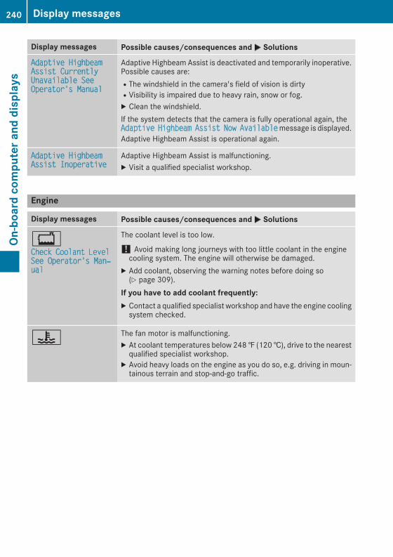
Display messages Possible causes/consequences andM Solutions
Adaptive HighbeamAssist CurrentlyUnavailable SeeOperator's Manual
Adaptive Highbeam Assist is deactivated and temporarily inoperative.Possible causes are:RThe windshield in the camera's field of vision is dirtyRVisibility is impaired due to heavy rain, snow or fog.X Clean the windshield.If the system detects that the camera is fully operational again, theAdaptive Highbeam Assist Now Availablemessage is displayed.Adaptive Highbeam Assist is operational again.
Adaptive HighbeamAssist Inoperative Adaptive Highbeam Assist is malfunctioning.X Visit a qualified specialist workshop.
Engine
Display messages Possible causes/consequences andM Solutions
+Check Coolant LevelSee Operator's Man‐ual
The coolant level is too low.
! Avoid making long journeys with too little coolant in the enginecooling system. The engine will otherwise be damaged.
X Add coolant, observing the warning notes before doing so(Y page 309).
If you have to add coolant frequently:X Contact a qualified specialist workshop and have the engine coolingsystem checked.
? The fan motor is malfunctioning.X At coolant temperatures below 248‡ (120†), drive to the nearestqualified specialist workshop.
X Avoid heavy loads on the engine as you do so, e.g. driving in moun-tainous terrain and stop-and-go traffic.
240 Display messagesOn
-board
computerand
displays

Display messages Possible causes/consequences andM Solutions
?Coolant Too HotStop Vehicle TurnEngine Off
The coolant is too hot.A warning tone also sounds.
G WARNINGDo not drive when your engine is overheated. This can cause somefluids which may have leaked into the engine compartment to catchfire.Steam from the overheated engine can also cause serious burnswhichcan occur just by opening the hood.There is a risk of injury.X Pull over and stop the vehicle safely and switch off the engine, pay-ing attention to road and traffic conditions.
X Secure the vehicle against rolling away (Y page 154).X Wait until the engine has cooled down.X Make sure that the air supply to the engine radiator is not blocked,e.g. by snow, slush or ice.
X Donot start the engine again until the displaymessage goes out andthe coolant temperature is below 248 ‡ (120 †). Otherwise, theengine could be damaged.
X Pay attention to the coolant temperature gauge.If the temperature increases again:X Visit a qualified specialist workshop immediately.Under normal operating conditions and with the specified coolantlevel, the coolant temperature may rise to 248 ‡ (120 †).
#See Operator's Man‐ual
The battery is not being charged.A warning tone also sounds.Possible causes are:Ra defective alternatorRa torn poly-V-beltRa malfunction in the electronics
! Do not continue driving. The engine could otherwise overheat.X Pull over and stop the vehicle safely and switch off the engine, pay-ing attention to road and traffic conditions.
X Secure the vehicle against rolling away (Y page 154).X Consult a qualified specialist workshop.
Display messages 241
On-board
computerand
displays
Z

Display messages Possible causes/consequences andM Solutions
#Stop Vehicle SeeOperator's Manual
The battery is no longer being charged and the condition of charge istoo low.A warning tone also sounds.X Pull over and stop the vehicle safely and switch off the engine, pay-ing attention to road and traffic conditions.
X Secure the vehicle against rolling away (Y page 154).X Observe the instructions in the# See Operator's Manualdisplay message.
X Consult a qualified specialist workshop.
#Stop Vehicle LeaveEngine Running
The battery condition of charge is too low.X Pull over and stop the vehicle safely as soon as possible, payingattention to road and traffic conditions. Do not continue drivingunder any circumstances.
X Leave the engine running.X Wait until the display message disappears before pulling away.
#Start Engine SeeOperator's Manual
The engine is switched off and the condition of charge is too low.X Switch off electrical consumers that you do not need, such as therear window defroster and interior lighting.
X Leave the engine running for a fewminutes or drive a long distance.The battery is being charged.
4Check Engine Oil AtNext Refueling
The engine oil level has dropped to the minimum level.A warning tone also sounds.
! Avoid long journeys with too little engine oil. The engine will oth-erwise be damaged.
X Check the oil level when next refueling, at the latest (Y page 308).X If necessary, add engine oil (Y page 308).If you have to add engine oil frequently:X Contact a qualified specialist workshop and have the enginechecked.
Information on approved engine oils can be obtained from a qualifiedspecialist workshop or on the Internet at http://bevo.mercedes-benz.com.
8Fuel Level Low
The fuel level has dropped into the reserve range.X Refuel at the nearest gas station.
C There is only a very small amount of fuel in the fuel tank.X Refuel at the nearest gas station without fail.
242 Display messagesOn
-board
computerand
displays

Display messages Possible causes/consequences andM Solutions
8Gas Cap Loose
The fuel filler cap is not closed correctly or the fuel system is leaking.X Check that the fuel filler cap is correctly closed.If the fuel filler cap is not correctly closed:X Close the fuel filler cap.If the fuel filler cap is correctly closed:X Visit a qualified specialist workshop.
¸Replace Air Filter
Vehicles with a diesel engine:The engine air filter is dirty and must be replaced.X Visit a qualified specialist workshop.
!Check Fuel Filter
Vehicles with a diesel engine:There is water in the fuel filter. The water must be drained off.X Visit a qualified specialist workshop.
Check Additive SeeOwner's Manual The DEF tank is almost empty.X Have the DEF tank filled as soon as possible at a qualified specialistworkshop (Y page 151).
The DEF system is malfunctioning.X Visit a qualified specialist workshop.
Remaining Starts:16 The DEF level has fallen to a minimum. You can start the engine afurther 16 times.X Have the DEF tank filled immediately at a qualified specialist work-shop (Y page 151).
i You can start the engine a further 16 times. If DEF is not added, itwill then not be possible to restart the engine. Refill the DEF tankwith approximately 1.3 gal (5.0 l) of DEF (Y page 151).
If the 10 starts display message is shown and a warning tone alsosounds, then the DEF system is malfunctioning.X Visit a qualified specialist workshop.
Display messages 243
On-board
computerand
displays
Z

Driving systems
Display messages Possible causes/consequences andM Solutions
ÀATTENTION ASSIST:Take a Break!
Based on certain criteria, ATTENTION ASSIST has detected fatigue ora lack of concentration on the part of the driver. A warning tone alsosounds.X If necessary, take a break.During long journeys, take regular breaks in good time so you getenough rest.
ÀATTENTION ASSISTInoperative
ATTENTION ASSIST is inoperative.X Visit a qualified specialist workshop.
ÁVehicle Rising
The vehicle is rising to the level you have selected.
ÁVehicle RisingPlease Wait
The vehicle level is too low when the vehicle is stationary. A warningtone also sounds.X Do not pull away.The vehicle level is set when the display message disappears.
ÁStop Vehicle Vehi‐cle Too Low
You have pulled away while the vehicle level is still too low.AIR BODY CONTROL sets the vehicle to the selected level after a shortperiod.Mercedes-AMG vehicles: the AMG sports suspension based on AIRBODY CONTROL sets the vehicle to the selected level after a shortperiod.X Pull over and stop the vehicle safely as soon as possible, payingattention to road and traffic conditions.
X Secure the vehicle against rolling away (Y page 154).X Wait until the display message disappears before pulling away.
AIR BODY CONTROL is faulty. A warning tone also sounds.Mercedes-AMG vehicles: the AMG sports suspension based on AIRBODY CONTROL is malfunctioning. A warning tone also sounds.X Do not drive at speeds above 50 mph (80 km/h).X Make only slight steering movements. Otherwise, the front fenderor the tires could be damaged if the steeringmovement is too large.
X Listen for scraping sounds.X Pull over and stop the vehicle safely, paying attention to road andtraffic conditions, and set a higher vehicle level.Depending on the malfunction, it may be possible to raise the vehi-cle.
X Visit a qualified specialist workshop.
244 Display messagesOn
-board
computerand
displays

Display messages Possible causes/consequences andM Solutions
ÁDrive More Slowly
You cannot change the vehicle level. Possible causes are:RYou are driving too fast for the selected vehicle levelRYou are driving too fast with a trailer or the trailer-coupling socket isbeing used, e.g. for a bicycle rack
X Drive more slowly and then select the desired vehicle level again(Y page 173).
X Observe the notes on towing a trailer (Y page 203).
ÁCompressor Is Cool‐ing
You have selected a higher vehicle level. The compressor first needsto cool down because of frequent level changes.X Drive in a manner appropriate for the current vehicle level.X Make sure that there is sufficient ground clearance.X Allow the compressor to cool down.When the compressor has cooled down, the display message dis-appears. The vehicle then continues rising to the selected level.
ÁMalfunction
AIR BODY CONTROL is malfunctioning. The vehicle's handling char-acteristics may be affected.Mercedes-AMG vehicles: the AMG sports suspension based on AIRBODY CONTROL is malfunctioning. The vehicle's handling character-istics may be affected.X Drive as appropriate for the current vehicle level, but do not exceed50 mph (80 km/h).
X Make sure that there is sufficient ground clearance.X Visit a qualified specialist workshop.
Lane Keeping AssistCurrently Unavaila‐ble See Operator'sManual or ActiveLane Keeping AssistCurrently Unavaila‐ble See Operator'sManual
Lane Keeping Assist or Active Lane Keeping Assist is deactivated andtemporarily inoperative.Possible causes are:RThe windshield in the camera's field of vision is dirty.RVisibility is impaired due to heavy rain, snow or fog.RThere have been no lane markings for an extended period.RThe lane markings are worn, dark or covered, e.g. by dirt or snow.When the causes stated above no longer apply, the display messagedisappears.Lane Keeping Assist or Active Lane Keeping Assist is operationalagain.If the display message does not disappear:X Pull over and stop the vehicle safely as soon as possible, payingattention to road and traffic conditions.
X Secure the vehicle against rolling away (Y page 154).X Clean the windshield.
Lane Keeping AssistInoperative orActive Lane KeepingAssist Inoperative
Lane Keeping Assist or Active Lane Keeping Assist is malfunctioning.X Visit a qualified specialist workshop.
Display messages 245
On-board
computerand
displays
Z

Display messages Possible causes/consequences andM Solutions
Blind Spot AssistCurrently Unavaila‐ble See Operator'sManual or ActiveBlind Spot AssistCurrently Unavaila‐ble See Operator'sManual
Blind Spot Assist or Active Blind Spot Assist is temporarily inoperative.Possible causes are:Rthe radar sensor system is outside the operating temperaturerange.Rthe radar sensor system is temporarily inoperative, e.g. due to elec-tromagnetic radiation emitted by nearby TV or radio stations orother sources of electromagnetic radiation.
When the causes stated above no longer apply, the display messagedisappears.Blind Spot Assist or Active Blind Spot Assist is operational again.If the display message does not disappear:X Pull over and stop the vehicle safely as soon as possible, payingattention to road and traffic conditions.
X Secure the vehicle against rolling away (Y page 154).X Restart the engine.
Blind Spot AssistInoperative orActive Blind SpotAssist Inoperative
Blind Spot Assist or Active Blind Spot Assist is malfunctioning.X Visit a qualified specialist workshop.
Park Assist Canceled The driver's door is open.X Repeat the parking gap measurement and parking process with thedriver's door closed.
You touched the multifunction steering wheel while steering inter-vention was active.X While steering intervention is active, make sure that the multifunc-tion steering wheel is not touched unintentionally.
The vehicle has started to skid and ESP® has intervened.X Use Active Parking Assist again later (Y page 178).
Park Assist Inoper‐ative PARKTRONIC is malfunctioning or faulty.X Follow the instructions and helpful hints in the "Problems withPARKTRONIC" section (Y page 178).
If the multifunction display still shows the display message:X Visit a qualified specialist workshop.
Active Parking Assist is unavailable or faulty.X Switch off the ignition and restart the engine.If Active Parking Assist continues to be unavailable (thej symboldoes not appear in the multifunction display):X Visit a qualified specialist workshop.
Park AssistSwitched Off The vehicle is parked. A warning tone also sounds.The display message disappears automatically.
246 Display messagesOn
-board
computerand
displays

Display messages Possible causes/consequences andM Solutions
Traffic Sign AssistCurrently Unavaila‐ble See Operator'sManual
Traffic Sign Assist is temporarily inoperative.Possible causes are:RThe windshield in the camera's field of vision is dirty.RVisibility is impaired due to heavy rain, snow or fog.X Clean the windshield.If the system detects that the camera is fully operational, the displaymessage disappears.Traffic Sign Assist is operational again.
Traffic Sign AssistInoperative Traffic Sign Assist is malfunctioning.X Visit a qualified specialist workshop.
ëOff
The HOLD function is deactivated. the vehicle is skidding.A warning tone also sounds.X Reactivate the HOLD function later (Y page 172).
The HOLD function is deactivated. When the brake pedal is firmlydepressed, an activation condition is not fulfilled.A warning tone also sounds.X Check the activation conditions for the HOLD function(Y page 172).
DISTRONIC PLUS Off DISTRONIC PLUS has been deactivated (Y page 169).If it was not deactivated by the driver, a warning tone also sounds.
DISTRONIC PLUS NowAvailable DISTRONIC PLUS is operational again after having been temporarilyunavailable. You can now reactivate DISTRONIC PLUS (Y page 165).
DISTRONIC PLUS Cur‐rently UnavailableSee Operator's Man‐ual
DISTRONIC PLUS is temporarily inoperative.Steering Assist and Stop&Go Pilot are temporarily inoperative.Possible causes are:Rthe radar sensor system is temporarily inoperative, e.g. due to elec-tromagnetic radiation emitted by nearby TV or radio stations orother sources of electromagnetic radiation.Rthe system is outside the operating temperature range.Rthe on-board voltage is too low.A warning tone also sounds.When the causes stated above no longer apply, the display messagedisappears.DISTRONIC PLUS is operational again.If the display message does not disappear:X Pull over and stop the vehicle safely as soon as possible, payingattention to road and traffic conditions.
X Secure the vehicle against rolling away (Y page 154).X Restart the engine.
Display messages 247
On-board
computerand
displays
Z

Display messages Possible causes/consequences andM Solutions
DISTRONIC PLUS Inop‐erative DISTRONIC PLUS is faulty.The following may have also failed:RBAS PLUS with Cross-Traffic AssistRPRE-SAFE® BrakeRSteering Assist and Stop&Go PilotA warning tone also sounds.X Visit a qualified specialist workshop.
DISTRONIC PLUS Sus‐pended You have depressed the accelerator pedal. DISTRONIC PLUS is nolonger controlling the speed of the vehicle.X Remove your foot from the accelerator pedal.
DISTRONIC PLUS- - - mph An activation condition for DISTRONIC PLUS is not fulfilled.X Check the activation conditions for DISTRONIC PLUS (Y page 165).
DTR+: SteeringAssist. CurrentlyUnavailable SeeOperator's Manual
Steering Assist and Stop&Go Pilot are temporarily inoperative.Possible causes are:RThe windshield in the camera's field of vision is dirty.RVisibility is impaired due to heavy rain, snow or fog.RThere are no lane markings for a longer period.RThe lane markings are worn, dark or covered, e.g. by dirt or snow.When the causes stated above no longer apply, the display messagedisappears.Steering Assist and Stop&Go Pilot are operative again.If the display message does not disappear:X Pull over and stop the vehicle safely as soon as possible, payingattention to road and traffic conditions.
X Secure the vehicle against rolling away (Y page 154).X Clean the windshield.
DTR+: SteeringAssist. Inoperative Steering Assist and Stop&Go Pilot are defective.However, the DISTRONIC PLUS functions are still available.A warning tone also sounds.X Visit a qualified specialist workshop.
Cruise Control Inop‐erative Cruise control is malfunctioning.A warning tone also sounds.X Visit a qualified specialist workshop.
248 Display messagesOn
-board
computerand
displays

Display messages Possible causes/consequences andM Solutions
Cruise Control- - - mphRA condition for activating cruise control has not been met.You have tried to store a speed below 20mph (30 km/h), for exam-ple.RESP® is deactivated. The yellow ESP® OFF warning lamp is lit.X If conditions permit, drive faster than 20 mph (30 km/h) and storethe speed.
orX Check the activation conditions for cruise control (Y page 162).orX Reactivate ESP® (Y page 220).orX Reactivate ESP® in Mercedes-AMG vehicles (Y page 71).
Cruise Control Off Cruise control has been deactivated.If a warning tone also sounds, cruise control has deactivated auto-matically (Y page 162).
Display messages 249
On-board
computerand
displays
Z

Tires
Display messages Possible causes/consequences and M Solutions
Check Tire PressureSoon Canada only:The tire pressure loss warning system has detected a significant lossin pressure.A warning tone also sounds.Possible causes:Ryou have changed the positions of the wheels and tires or installednew wheels and tiresRthe tire pressure in one or more tires has dropped significantly
G WARNINGTire pressures that are too low pose the following hazards:Rthey may burst, especially as the load and vehicle speed increase.Rthey may wear excessively and/or unevenly, which may greatlyimpair tire traction.Rthe driving characteristics, as well as steering and braking, may begreatly impaired.
There is a risk of an accident.X Stop the vehicle without making any sudden steering or brakingmaneuvers. Pay attention to the traffic conditions as you do so.
X Secure the vehicle against rolling away (Y page 154).X Check the tires and, if necessary, follow the instructions for a flattire (Y page 321).
X Check the tire pressures and, if necessary, correct the tire pressure.X Restart the tire pressure loss warning system when the tire pres-sure is correct (Y page 343).
Check Tire PressureThen Restart RunFlat IndicatorCanada only:The tire pressure loss warning system generated a display messageand has not been restarted since.X Set the correct tire pressure in all four tires.X Restart the tire pressure loss warning system (Y page 343).
Run Flat IndicatorInoperative Canada only:The tire pressure loss warning system is faulty.X Visit a qualified specialist workshop.
Please Correct TirePressure The tire pressure is too low in at least one of the tires, or the tirepressure difference between the wheels is too great.X Check the tire pressures at the next opportunity (Y page 345).X If necessary, correct the tire pressure.X Restart the tire pressure monitor (Y page 345).
250 Display messagesOn
-board
computerand
displays

Display messages Possible causes/consequences andM Solutions
Check Tires The tire pressure in one or more tires has dropped significantly. Thewheel position is displayed in the multifunction display.A warning tone also sounds.
G WARNINGTire pressures that are too low pose the following hazards:Rthey may burst, especially as the load and vehicle speed increase.Rthey may wear excessively and/or unevenly, which may greatlyimpair tire traction.Rthe driving characteristics, as well as steering and braking, may begreatly impaired.
There is a risk of an accident.X Stop the vehicle without making any sudden steering or brakingmaneuvers. Pay attention to the traffic conditions as you do so.
X Secure the vehicle against rolling away (Y page 154).X Check the tires and, if necessary, follow the instructions for a flattire (Y page 321).
X Check the tire pressure (Y page 345).X If necessary, correct the tire pressure.
Warning Tire Mal‐function The tire pressure in one ormore tires has dropped suddenly. Thewheelposition is shown in the multifunction display.
G WARNINGDriving with a flat tire poses a risk of the following hazards:Ra flat tire affects the ability to steer or brake the vehicleRyou could lose control of the vehicleRcontinued driving with a flat tire will cause excessive heat build-upand possibly a fire
There is a risk of an accident.X Stop the vehicle without making any sudden steering or brakingmaneuvers. Pay attention to the traffic conditions as you do so.
X Secure the vehicle against rolling away (Y page 154).X Check the tires and, if necessary, follow the instructions for a flattire (Y page 321).
Tire Press. MonitorCurrently Unavaila‐bleBecause there is interference from a strong source of radio waves, nosignals from the tire pressure sensors are detected. The tire pressuremonitor is temporarily malfunctioning.X Drive on.The tire pressure monitor restarts automatically as soon as theproblem has been resolved.
TirePress. Sen‐sor(s) Missing There is no signal from the tire pressure sensor of one or several tires.The pressure of the affected tire is not displayed in the multifunctiondisplay.X Have the faulty tire pressure sensor replaced at a qualified special-ist workshop.
Display messages 251
On-board
computerand
displays
Z

Display messages Possible causes/consequences andM Solutions
Tire Pressure Moni‐tor Inoperative NoWheel SensorsThe wheels mounted do not have a suitable tire pressure sensor. Thetire pressure monitor is deactivated.X Mount wheels with suitable tire pressure sensors.The tire pressure monitor is activated automatically after driving fora few minutes.
Tire Press. MonitorInoperative The tire pressure monitor is faulty.X Visit a qualified specialist workshop.
Vehicle
Display messages Possible causes/consequences andM Solutions
Shift to 'P' or 'N'to Start Engine You have attempted to start the engine with the transmission in posi-tionk orh.X Shift the transmission to positionj ori .
Apply Brake toShift from 'P' You have attempted to shift the transmission to positionh,k oriwithout depressing the brake pedal.X Depress the brake pedal.
To Deselect P or N,Depress Brake andStart EngineWith the engine switched off, you have attempted to shift the trans-mission out of positionj ori into another transmission position.X Depress the brake pedal.X Start the engine.
Transmission Not inP Risk of VehicleRolling AwayThe driver's door is open or not fully closed and the transmission is inpositionk,i orh.A warning tone also sounds.
G WARNINGThe vehicle may roll away.There is a risk of an accident.X Shift the transmission to positionj.X Secure the vehicle against rolling away (Y page 154).X Close the driver's door completely.
Only Shift to 'P'when Vehicle is Sta‐tionaryThe vehicle is moving.X Pull over and stop the vehicle safely as soon as possible, payingattention to road and traffic conditions.
X Shift the transmission to positionj.
252 Display messagesOn
-board
computerand
displays
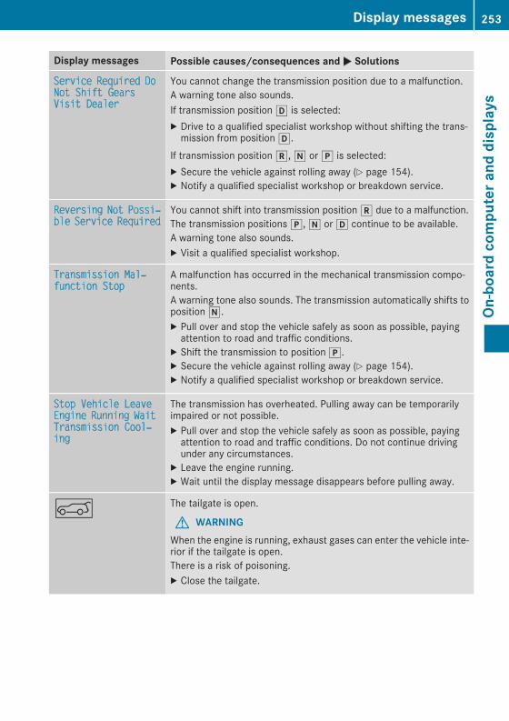
Display messages Possible causes/consequences andM Solutions
Service Required DoNot Shift GearsVisit DealerYou cannot change the transmission position due to a malfunction.A warning tone also sounds.If transmission positionh is selected:X Drive to a qualified specialist workshop without shifting the trans-mission from positionh.
If transmission positionk,i orj is selected:X Secure the vehicle against rolling away (Y page 154).X Notify a qualified specialist workshop or breakdown service.
Reversing Not Possi‐ble Service Required You cannot shift into transmission positionk due to a malfunction.The transmission positionsj,i orh continue to be available.A warning tone also sounds.X Visit a qualified specialist workshop.
Transmission Mal‐function Stop A malfunction has occurred in the mechanical transmission compo-nents.A warning tone also sounds. The transmission automatically shifts topositioni.X Pull over and stop the vehicle safely as soon as possible, payingattention to road and traffic conditions.
X Shift the transmission to positionj.X Secure the vehicle against rolling away (Y page 154).X Notify a qualified specialist workshop or breakdown service.
Stop Vehicle LeaveEngine Running WaitTransmission Cool‐ing
The transmission has overheated. Pulling away can be temporarilyimpaired or not possible.X Pull over and stop the vehicle safely as soon as possible, payingattention to road and traffic conditions. Do not continue drivingunder any circumstances.
X Leave the engine running.X Wait until the display message disappears before pulling away.
A The tailgate is open.
G WARNINGWhen the engine is running, exhaust gases can enter the vehicle inte-rior if the tailgate is open.There is a risk of poisoning.X Close the tailgate.
Display messages 253
On-board
computerand
displays
Z

Display messages Possible causes/consequences andM Solutions
? The hood is open. A warning tone also sounds.
G WARNINGThe open hood may block your view when the vehicle is in motion.There is a risk of an accident.X Pull over and stop the vehicle safely as soon as possible, payingattention to road and traffic conditions.
X Secure the vehicle against rolling away (Y page 154).X Close the hood.
C At least one door is open. A warning tone also sounds.X Close all the doors.
_Rear Left BackrestNot Latched or RearRight Backrest NotLatched
Vehicle with through-loading feature in the rear bench seat:The backrest in the rear is not engaged on the left-hand and/or right-hand side.X Push the backrest back until it engages.
_Rear Center Back‐rest Not Engaged
Vehicle with through-loading facility in the rear compartment:The center rear seat backrest is not engaged.X Push the backrest back until it engages.
ÐPower Steering Mal‐function See Opera‐tor's Manual
The power steering is malfunctioning.A warning tone also sounds.
G WARNINGYou will need to use more force to steer.There is a risk of an accident.X Check whether you are able to apply the extra force required.If you are able to steer safely:X Drive on carefully.X Visit a qualified specialist workshop immediately.If you are unable to steer safely:X Do not drive on.X Consult a qualified specialist workshop.
Phone No Service Your vehicle is outside the network provider's transmitter/receiverrange.X Wait until the mobile phone operational readiness symbol appearsin the multifunction display.
¥Check Washer Fluid
The washer fluid level in the washer fluid reservoir has dropped belowthe minimum.X Add washer fluid (Y page 310).
254 Display messagesOn
-board
computerand
displays

SmartKey
Display messages Possible causes/consequences andM Solutions
ÂKey Does Not Belongto Vehicle
You have put the wrong SmartKey in the ignition lock.X Use the correct SmartKey.
ÂTake Your Key fromIgnition
The SmartKey is in the ignition lock.A warning tone soundsX Remove the SmartKey.
ÂObtain a New Key
The SmartKey needs to be replaced.X Visit a qualified specialist workshop.
ÂReplace Key Battery
The SmartKey battery is discharged.X Change the batteries (Y page 80).
ÂDon't Forget YourKey
The SmartKey is not in the ignition lock. You have opened the driver'sdoor with the engine switched off. A warning tone soundsThis display message is displayed for amaximum of 60 seconds and issimply a reminder.X Take the SmartKey with you when you leave the vehicle.
ÂKey Not Detected(white display message)
The SmartKey is currently undetected.X Change the location of the SmartKey in the vehicle.If the SmartKey still cannot be detected:X Insert the SmartKey into the ignition lock and turn it to the desiredposition.
ÂKey Not Detected(red display message)
The SmartKey is not in the vehicle.A warning tone also sounds.If the engine is switched off, you can no longer lock the vehicle cen-trally or start the engine.X Pull over and stop the vehicle safely as soon as possible, payingattention to road and traffic conditions.
X Secure the vehicle against rolling away (Y page 154).X Locate the SmartKey.X Pressa on the steering wheel to confirm the display message.
Display messages 255
On-board
computerand
displays
Z

Display messages Possible causes/consequences andM Solutions
Because there is interference from a strong source of radio waves, theSmartKey is not detected whilst the engine is running.A warning tone also sounds.X Pull over and stop the vehicle safely as soon as possible, payingattention to road and traffic conditions.
X Secure the vehicle against rolling away (Y page 154).X Insert the SmartKey into the ignition lock and drive in SmartKeymode.
ÂRemove 'Start' But‐ton and Insert Key
The SmartKey is continually undetected.The SmartKey detection function has a temporary malfunction or isfaulty. A warning tone also sounds.X Insert the SmartKey into the ignition lock and turn it to the desiredposition.
X Visit a qualified specialist workshop.
Warning and indicator lamps in the instrument cluster
General notesSome systems carry out a self-diagnosis when the ignition is switched on. Therefore, some indicatorand warning lamps may light up or flash temporarily. This behavior is non-critical. These indicatorand warning lamps only indicate a malfunction if they light up or flash after starting the engine orwhilst driving.
Safety
Seat belts
Warning/indicatorlamp
N Signal typePossible causes/consequences andM Solutions
ü N After starting the engine, the red seat belt warning lamp lights up for six sec-onds.The seat belt warning lamp reminds the driver and front passenger to fasten theirseat belts.X Fasten your seat belt (Y page 47).
ü N After starting the engine, the red seat belt warning lamp lights up. In addition, awarning tone sounds for up to six seconds.The driver's seat belt is not fastened.X Fasten your seat belt (Y page 47).The warning tone ceases.
256 Warning and indicator lamps in the instrument clusterOn
-board
computerand
displays

Warning/indicatorlamp
N Signal typePossible causes/consequences and M Solutions
ü N The red seat belt warning lamp lights up after the engine starts, as soon as thedriver's or the front-passenger door is closed.The driver or front passenger has not fastened their seat belt.X Fasten your seat belt (Y page 47).The warning lamp goes out.
There are objects on the front-passenger seat.X Remove the objects from the front-passenger seat and stow them in a secureplace.The warning lamp goes out.
ü N The red seat belt warning lamp flashes and an intermittent audible warningsounds.The driver or front passenger has not fastened their seat belt. The vehicle is beingdriven faster than 15mph (25 km/h) or has briefly been driven faster than 15mph(25 km/h).X Fasten your seat belt (Y page 47).The warning lamp goes out and the intermittent warning tone ceases.
There are objects on the front-passenger seat. The vehicle is being driven fasterthan 15 mph (25 km/h) or has briefly been driven faster than 15 mph (25 km/h).X Remove the objects from the front-passenger seat and stow them in a secureplace.The warning lamp goes out and the intermittent warning tone ceases.
Warning and indicator lamps in the instrument cluster 257
On-board
computerand
displays
Z

Safety systems
Warning/indicatorlamp
N Signal typePossible causes/consequences andM Solutions
$J N$ (USA only),J (Canada only): the red brake system warning lamp is litwhile the engine is running.A warning tone also sounds.
G WARNINGThe brake boosting effect ismalfunctioning and the braking characteristicsmay beaffected.There is a risk of an accident.X Pull over and stop the vehicle safely as soon as possible, paying attention to roadand traffic conditions. Do not continue driving under any circumstances.
X Secure the vehicle against rolling away (Y page 154).X Consult a qualified specialist workshop.X Observe the additional display messages in the multifunction display.
$J N$ (USA only),J (Canada only): the red brake system warning lamp lightsup while the engine is running.A warning tone also sounds.There is not enough brake fluid in the brake fluid reservoir.
G WARNINGThe braking effect may be impaired.There is a risk of an accident.X Pull over and stop the vehicle safely as soon as possible, paying attention to roadand traffic conditions. Do not continue driving under any circumstances.
X Secure the vehicle against rolling away (Y page 154).X Do not add brake fluid. Adding more will not correct the malfunction.X Consult a qualified specialist workshop.X Observe the additional display messages in the multifunction display.
$ N USA only: the red brake system warning lamp is lit while the engine is running.The multifunction display also shows a display message with the# symbol.The brake pads/linings have reached their wear limit.X Visit a qualified specialist workshop.
258 Warning and indicator lamps in the instrument clusterOn
-board
computerand
displays

Warning/indicatorlamp
N Signal typePossible causes/consequences and M Solutions
! N The yellow ABS warning lamp is lit while the engine is running.ABS (anti-lock braking system) is malfunctioning.If there is an additional warning tone, the EBD (electronic brake force distribution)is malfunctioning.Other driving systems and driving safety systems may also malfunction.
G WARNINGThe brake system continues to function normally, but without the functions listedabove. The front and rear wheels could therefore lock if you brake hard, for exam-ple.The steerability and braking characteristics may be severely affected. The brakingdistance in an emergency braking situation can increase.If ESP® is not operational, ESP® is unable to stabilize the vehicle.There is an increased risk of skidding and an accident.X Observe the additional display messages in the multifunction display.X Drive on carefully.X Visit a qualified specialist workshop immediately.If the ABS control unit is faulty, there is also a possibility that other systems, suchas the navigation system or the automatic transmission, will not be available.
$J÷!
N$ (USA only),J (Canada only): the red brakewarning lamp and the yellowESP® and ABS warning lamps are lit while the engine is running.ABS and ESP® are malfunctioning.Other driving systems and driving safety systems may also malfunction.
G WARNINGThe brake system continues to function normally, but without the functions listedabove. The front and rear wheels could therefore lock if you brake hard, for exam-ple.The steerability and braking characteristics may be severely affected. The brakingdistance in an emergency braking situation can increase.If ESP® is not operational, ESP® is unable to stabilize the vehicle.There is an increased risk of skidding and an accident.X Observe the additional display messages in the multifunction display.X Drive on carefully.X Visit a qualified specialist workshop immediately.
Warning and indicator lamps in the instrument cluster 259
On-board
computerand
displays
Z
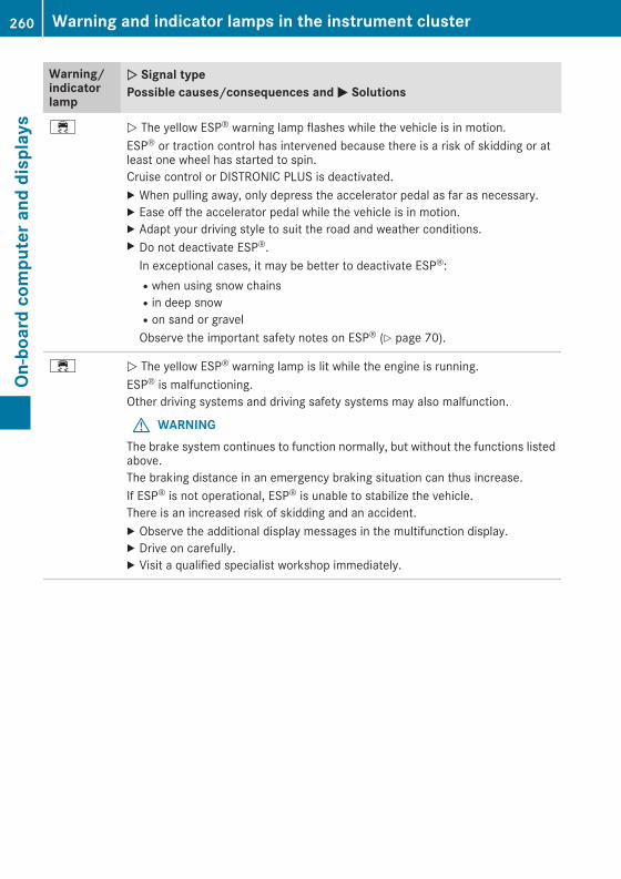
Warning/indicatorlamp
N Signal typePossible causes/consequences and M Solutions
÷ N The yellow ESP® warning lamp flashes while the vehicle is in motion.ESP® or traction control has intervened because there is a risk of skidding or atleast one wheel has started to spin.Cruise control or DISTRONIC PLUS is deactivated.X When pulling away, only depress the accelerator pedal as far as necessary.X Ease off the accelerator pedal while the vehicle is in motion.X Adapt your driving style to suit the road and weather conditions.X Do not deactivate ESP®.In exceptional cases, it may be better to deactivate ESP®:Rwhen using snow chainsRin deep snowRon sand or gravelObserve the important safety notes on ESP® (Y page 70).
÷ N The yellow ESP® warning lamp is lit while the engine is running.ESP® is malfunctioning.Other driving systems and driving safety systems may also malfunction.
G WARNINGThe brake system continues to function normally, but without the functions listedabove.The braking distance in an emergency braking situation can thus increase.If ESP® is not operational, ESP® is unable to stabilize the vehicle.There is an increased risk of skidding and an accident.X Observe the additional display messages in the multifunction display.X Drive on carefully.X Visit a qualified specialist workshop immediately.
260 Warning and indicator lamps in the instrument clusterOn
-board
computerand
displays

Warning/indicatorlamp
N Signal typePossible causes/consequences and M Solutions
å N The yellow ESP® OFF warning lamp is lit while the engine is running or the ECOstart/stop function is activated.ESP® is deactivated.
G WARNINGIf ESP® is switched off, ESP® is unable to stabilize the vehicle.Further driving systems or driving safety systems are thus restricted, e.g. ActiveBlind Spot Assist. The system does not perform braking actions.There is an increased risk of skidding and an accident.X Reactivate ESP®.In exceptional cases, it may be better to deactivate ESP®:Rwhen using snow chainsRin deep snowRon sand or gravelObserve the important safety notes on ESP® (Y page 70).
X Adapt your driving style to suit the road and weather conditions.If ESP® cannot be activated:X Drive on carefully.X Contact a qualified specialist workshop and have ESP® checked.
M N Mercedes-AMG vehicles:The yellow SPORT handling mode warning lamp is lit while the engine is running.SPORT handling mode is activated.
G WARNINGWhen SPORT handlingmode is switched on, ESP® is unable to stabilize the vehicle.There is an increased risk of skidding and an accident.X Only activate SPORT handling mode in accordance with the conditions descri-bed in the "Activating/deactivating ESP®" section (Y page 71).
Warning and indicator lamps in the instrument cluster 261
On-board
computerand
displays
Z

Warning/indicatorlamp
N Signal typePossible causes/consequences and M Solutions
F! NF (USA only),! (Canada only): the red indicator lamp for the electricparking brake flashes or is lit and/or the yellow warning lamp for the electricparking brake is lit.X Observe the additional display messages in the multifunction display.
6 N The red restraint system warning lamp is lit while the engine is running.The restraint system is malfunctioning.
G WARNINGThe air bags or Emergency Tensioning Devices may either be triggered uninten-tionally or, in the event of an accident, may not be triggered.There is an increased risk of injury.X Observe the additional display messages in the multifunction display.X Drive on carefully.X Contact a qualified specialist workshop and have the restraint system checked.For further information about the restraint system, see (Y page 43).
262 Warning and indicator lamps in the instrument clusterOn
-board
computerand
displays

Engine
Warning/indicatorlamp
N Signal typePossible causes/consequences andM Solutions
; N The yellow Check Engine warning lamp lights up while the engine is running.There may be a malfunction, for example:Rin the engine managementRin the fuel injection systemRin the exhaust systemRin the ignition system (for vehicles with gasoline engines)Rin the fuel systemThe emission limit values may be exceeded and the engine may be in emergencymode.X Visit a qualified specialist workshop immediately.In some states, youmust immediately visit a qualified specialist workshop as soonas the yellow Check Engine warning lamp lights up. This is due to the legal require-ments in effect in these states. If in doubt, check whether such legal regulationsapply in the state in which you are currently driving.Vehicles with a diesel engine: the fuel tank has been run dry (Y page 151).X Start the engine three to four times after refueling.If the yellow Check Engine warning lamp goes out, emergency running mode iscanceled. The vehicle need not be checked.
8 N The yellow reserve fuel warning lamp lights up while the engine is running.The fuel level has dropped into the reserve range.X Refuel at the nearest gas station.
8 N The yellow reserve fuel warning lamp flashes while the vehicle is in motion.In addition, the; Check Engine warning lamp may light up.The fuel filler cap is not closed correctly or the fuel system is leaking.X Check that the fuel filler cap is correctly closed.X If the fuel filler cap is not correctly closed: close the fuel filler cap.X If the fuel filler cap is closed: visit a qualified specialist workshop.
? N The red coolant warning lamp lights up while the engine is running and thecoolant temperature gauge is at the start of the scale.The temperature sensor for the coolant temperature gauge is malfunctioning.The coolant temperature is no longer being monitored. There is a risk of enginedamage if the coolant temperature is too high.X Pull over and stop the vehicle safely and switch off the engine, paying attentionto road and traffic conditions. Do not continue driving under any circumstances.
X Secure the vehicle against rolling away (Y page 154).X Consult a qualified specialist workshop.
Warning and indicator lamps in the instrument cluster 263
On-board
computerand
displays
Z

Warning/indicatorlamp
N Signal typePossible causes/consequences and M Solutions
? N The red coolant warning lamp comes on while the engine is running.The coolant level is too low.If the coolant level is correct, the airflow to the engine radiator may be blocked orthe electric engine radiator fan may be defective.The coolant is too hot and the engine is no longer being cooled sufficiently.X Observe the additional display messages in the multifunction display.X Pull over and stop the vehicle safely and switch off the engine, paying attentionto road and traffic conditions.
X Secure the vehicle against rolling away (Y page 154).X Leave the vehicle and keep a safe distance from the vehicle until the engine hascooled down.
X Check the coolant level and add coolant, observing the warning notes(Y page 309).
X If you have to add coolant frequently, have the engine cooling system checked.X Make sure that the air supply to the engine radiator is not blocked, e.g. by snow,slush or ice.
X Do not start the engine again until the coolant temperature is below 248 ‡(120 †). Otherwise, the engine could be damaged.
X Drive to the nearest qualified specialist workshop.X Avoid heavy loads on the engine as you do so, e.g. driving inmountainous terrainand stop-and-go traffic.
? N The red coolant warning lamp comes on while the engine is running. A warningtone also sounds.The coolant temperature has exceeded 248 ‡ (120 †). The airflow to the engineradiator may be blocked or the coolant level may be too low.
G WARNINGThe engine is not being cooled sufficiently and may be damaged.Do not drive when your engine is overheated. This can cause some fluids whichmay have leaked into the engine compartment to catch fire.Steam from the overheated engine can also cause serious burns which can occurjust by opening the hood.There is a risk of injury.X Observe the additional display messages in the multifunction display.X Pull over and stop the vehicle safely and switch off the engine, paying attentionto road and traffic conditions.
X Secure the vehicle against rolling away (Y page 154).X Leave the vehicle and keep a safe distance from the vehicle until the engine hascooled down.
X Check the coolant level and add coolant, observing the warning notes(Y page 309).
X If you have to add coolant frequently, have the engine cooling system checked.X Make sure that the air supply to the engine radiator is not blocked, e.g. by snow,slush or ice.
264 Warning and indicator lamps in the instrument clusterOn
-board
computerand
displays
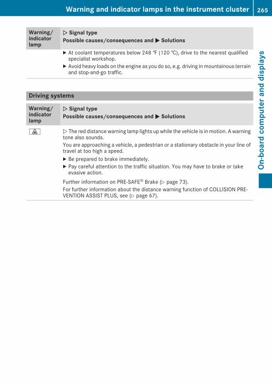
Warning/indicatorlamp
N Signal typePossible causes/consequences and M Solutions
X At coolant temperatures below 248 ‡ (120 †), drive to the nearest qualifiedspecialist workshop.
X Avoid heavy loads on the engine as you do so, e.g. driving inmountainous terrainand stop-and-go traffic.
Driving systems
Warning/indicatorlamp
N Signal typePossible causes/consequences and M Solutions
· N The red distance warning lamp lights up while the vehicle is inmotion. A warningtone also sounds.You are approaching a vehicle, a pedestrian or a stationary obstacle in your line oftravel at too high a speed.X Be prepared to brake immediately.X Pay careful attention to the traffic situation. You may have to brake or takeevasive action.
Further information on PRE‑SAFE® Brake (Y page 73).For further information about the distance warning function of COLLISION PRE-VENTION ASSIST PLUS, see (Y page 67).
Warning and indicator lamps in the instrument cluster 265
On-board
computerand
displays
Z

Tires
Warning/indicatorlamp
N Signal typePossible causes/consequences and M Solutions
h N The yellow tire pressuremonitorwarning lamp (pressure loss/malfunction) is lit.The tire pressuremonitor has detected a loss of pressure in at least one of the tires.
G WARNINGTire pressures that are too low pose the following hazards:Rthey may burst, especially as the load and vehicle speed increase.Rthey may wear excessively and/or unevenly, which may greatly impair tire trac-tion.Rthe driving characteristics, as well as steering and braking, may be greatlyimpaired.There is a risk of an accident.
X Stop the vehicle withoutmaking any sudden steering or brakingmaneuvers. Payattention to the traffic conditions as you do so.
X Secure the vehicle against rolling away (Y page 154).X Observe the additional display messages in the multifunction display.X Check the tires and, if necessary, follow the instructions for a flat tire(Y page 321).
X Check the tire pressure (Y page 345).X If necessary, correct the tire pressure.
h N The yellow tire pressure monitor warning lamp (pressure loss/malfunction)flashes for approximately one minute and then remains lit.The tire pressure monitor is faulty.
G WARNINGThe system is possibly unable to recognize or register low tire pressure.There is a risk of an accident.X Observe the additional display messages in the multifunction display.X Visit a qualified specialist workshop immediately.
266 Warning and indicator lamps in the instrument clusterOn
-board
computerand
displays

Vehicle
Warning/indicatorlamp
N Signal typePossible causes/consequences and M Solutions
Ð N The red power steering warning lamp is lit while the engine is running.The power steering is malfunctioning.A warning tone also sounds.
G WARNINGYou will need to use more force to steer.There is a risk of an accident.X Check whether you are able to apply the extra force required.If you are able to steer safely:X Drive on carefully.X Visit a qualified specialist workshop immediately.If you are unable to steer safely:X Do not drive on.X Consult a qualified specialist workshop.
Warning and indicator lamps in the instrument cluster 267
On-board
computerand
displays
Z

General notes
The multimedia system section in this Opera-tor's Manual describes the basic principles foroperation. More information can be found in theDigital Operator's Manual.
Important safety notes
G WARNINGIf you operate information systems and com-munication equipment integrated in the vehi-cle while driving, you will be distracted fromtraffic conditions. You could also lose controlof the vehicle. There is a risk of an accident.Only operate the equipment when the trafficsituation permits. If you are not sure that thisis possible, park the vehicle paying attentionto traffic conditions and operate the equip-ment when the vehicle is stationary.
Youmust observe the legal requirements for thecountry in which you are currently driving whenoperating the multimedia system.The multimedia system calculates the route tothe destination without taking the following intoaccount, for example:Rtraffic lightsRstop and yield signsRparking or stopping restrictionsRroad narrowingRother road and traffic rules and regulationsThe multimedia system may give incorrect nav-igation recommendations if the actual street/traffic situation does not correspond with thedigital map's data.For example:Ra diverted routeRthe road layout or the direction of a one-waystreet has been changed
For this reason, you must always observe roadand traffic rules and regulations during yourjourney. Road and traffic rules and regulationsalways have priority over multimedia systemdriving recommendations.Navigation announcements are intended todirect you while driving without diverting yourattention from the road and driving.
Please always use this feature instead of con-sulting the map display for directions. Lookingat the icons ormap display can distract you fromtraffic conditions and driving, and increase therisk of an accident.This equipment complies with FCC radiationexposure limits set forth for uncontrolled equip-ment and meets the FCC radio frequency (RF)Exposure Guidelines in Supplement C to OET65.This equipment has very low levels of RF energythat is deemed to comply without maximumpermissive exposure evaluation (MPE). How-ever, it is recommended to install it at a distanceof at least 8 inches (approx. 20 cm) between theradiation source and a person's body (notincluding limbs such as hands, wrists, feet andlegs).
G WARNINGModifications to electronic components, theirsoftware as well as wiring can impair theirfunction and/or the function of other net-worked components. In particular, systemsrelevant to safety could also be affected. As aresult, these may no longer function as inten-ded and/or jeopardize the operating safety ofthe vehicle. There is an increased risk of anaccident and injury.Never tamper with the wiring as well as elec-tronic components or their software. Youshould have all work to electrical and elec-tronic equipment carried out at a qualifiedspecialist workshop.
Function restrictions
For safety reasons, some functions are restric-ted or unavailable while the vehicle is in motion.You will notice this, for example, because eitheryou will not be able to select certain menu itemsor a message will appear to this effect.
268 Function restrictionsMultim
ediasystem
Operating system
Overview
General notesWearing polarized sunglasses may impair yourability to read the display.The display has an automatic temperature-con-trolled switch-off feature. The brightness isautomatically reduced if the temperature is toohigh. The display may temporarily switch offcompletely.
Cleaning instructions! Do not touch the display. The display has avery sensitive high-gloss surface; there is arisk of scratching. If you have to clean thescreen, however, use a mild cleaning agentand a soft, lint-free cloth.
The display must be switched off and havecooled down before you start cleaning. Do notapply pressure to the display surface whencleaning it, as this could cause irreversible dam-age to the display.
Switching the multimedia systemon/offX Press theÜ button on the center consoleto the right of the controller.
Adjusting the volumeX Turn the thumbwheel to the right of the con-troller.
The volume is adjusted:Rfor the currently selected media sourceRduring traffic or navigation announcementsRin hands-free mode during a phone call
Switching the sound on or offX Press the thumbwheel to the right of the con-troller.
orX Press the8 button on the multifunctionsteering wheel.If the audio output is switched off, the statusline will show the8 symbol. If you switchthe media source or change the volume, thesound is automatically switched on.
i Navigation announcements will be heardeven if the sound is muted.
FunctionsThe multimedia system has the following func-tions:RRadio modeRMedia mode with media searchRSound systemsRNavigation systemCOMAND: navigation via the hard driveAudio 20: navigation via SD cardRCommunication functionsRSIRIUS Weather (COMAND)RVehicle functions with system settingsRFavorites functions
ControllerThe controller in the center console lets you:Rselect menu items on the displayRenter charactersRselect a destination on the mapRsave entriesThe controller can be:Rturned3Rslid left or right1Rslid forwards or back4Rslid diagonally2Rpressed briefly or pressed and held7
Back buttonYou can use the% button to exit amenu or tocall up the basic display of the current operatingmode.X To exit the menu: briefly press the%button.The multimedia system changes to the nexthigher menu level in the current operatingmode.
X To call up the basic display: press the%button for longer than two seconds.The multimedia system changes to the basicdisplay of the current operating mode.
Operating system 269
Multim
ediasystem
Z

Touchpad
Switching the touchpad on/offMultimedia system:X Select VehicleQSystem Set‐tingsQTouchpadQActivate Touch‐pad.The touchpad is switched on O or off ª.
Operating the touchpad
: Touch-sensitive surface; Favorites button= Calls up quick access for audio? Back buttonNavigating in menus and lists can be done viatouch-sensitive surface: by swiping withyour finger.X To select themenu item: swipe up, down, tothe left or right.
X Press the touchpad.X To move the digital map: swipe in all direc-tions.
Swiping with two fingers, e.g. using this func-tion:X To show or hide the audio menu: swipe upor down with two fingers.
X To increase or reduce the vehicle andsound settings: turn two fingers to the rightor left.
X To zoom in and out of the map: move twofingers together or apart.
Character entry with handwriting rec-ognition
Entering charactersX Use one finger to write characters on the sur-face.The character is entered in the input line. Ifthe character that you have entered can beinterpreted in different ways, these charactersuggestions are displayed.
X If character suggestions are shown, turn andpress the controller.
X Resume the character entry on the touchpad.
Handwriting recognition
: Active input line; Inserts a space= Character entered on the touchpad? Deletes characters (Example: COMAND)X To display the menu: press the touchpad.
: To exit the menu; To return to handwriting recognition= To use the phone book or text templates
(COMAND)? To select the input line or changes the posi-
tion of the cursorA To switch the languageB To finish character entry
270 Operating systemMultim
ediasystem

X To select the input line: selectp.X Swipe up or down.X To move the cursor within the input line:selectp.
X Swipe to the left or right.X To delete characters: swipe to the left if aninput line is selected.
X To confirm the entry: press the touchpad.
Switching the text reader function of thehandwriting recognition on/offMultimedia system:X Select VehicleQSystem Set‐tingsQTouchpadQRead Out Hand‐writing Recognition .The read-aloud function is switched on O oroff ª.
Quick access for audio
Changing the station/music track
Depending on the audio source that is currentlyactivated, you can use this function to select thenext station or music track.X Swipe upwards with two fingers on the touch-pad.The current audio source is displayed.
X To select the previous or next station/music track: glide to the right or left.The selected station/music track is played.
Switching the character entry betweentouchpad and controllerRequirement: an input line for text, numbers orcharacters has been selected.
X To switch to the controller: press the con-troller.Character entry using the controller is active.
X To switch to the touchpad: press the touch-pad with your finger.Handwriting recognition on the touchpad isactive.
Favorites
Calling up and exiting favoritesX To call up: press theg button on the con-troller or on the touchpad.
X Select a favorite, e.g. Vehicle.The favorites are displayed.
X To exit: press theg button again.
Adding favorites
Adding a predefined favorite
: Adds a new favorite; Renames a selected favorite= Moves a selected favorite? Deletes a selected favoriteX Press theg button.X Slide6 the controller.The menu bar is shown.
X Select Reassign.The categories are displayed.
X Select a category.The favorites are displayed.
X Select a favorite.X Add a favorite at the desired position.If a favorite has already been added at thisposition, it will be overwritten.
Operating system 271
Multim
ediasystem
Z

Adding your own favoriteX Select VehicleQClimate Control.X Press and hold theg button until thefavorites are displayed.
X Add a favorite at the desired position.If a favorite has already been added at thisposition, it will be overwritten.
Climate control settings
General notesYou can adjust the climate control settingsusing the climate control bar or the climate con-trol menu.Important climate control functions can be setin the climate control bar:RTemperatureRAirflowRAir distributionThe climate control bar is visible in most dis-plays.You can find all available climate control func-tions in the climate control menu. You can usethe climate control bar to switch to the climatecontrol menu.
Overview
Climate control bar (COMAND): Adjusts temperature, air distribution on the
left and airflow, displays the current settings; Calls up the climate control menu, displays
the current cooling and climate mode set-tings
= Adjusts temperature and air distribution onthe right, displays the current settings
There may be fewer settings or none dependingon your vehicle's equipment.
Calling up the climate control barMultimedia system:X Select Vehicle.The vehicle menu is displayed.
X Slide6 the controller repeatedly until theclimate control bar is activated.
Calling up the climate control menuMultimedia system:X Select Vehicle.The vehicle menu is displayed.
X Slide6 the controller repeatedly until theclimate control bar is activated.
X To select from climate control bar;: turnand press the controller.The menu for selecting the climate controlfunction is activated.
X To select the climate control function: turnand press the controller.The selected climate control functionappears.
Settings in the climate menu
Adjusting the climate mode settingsThe climate mode determines the type of air-flow. The setting is active when the air-condi-tioning system is set toà (Y page 125).X Call up the climate control menu(Y page 272).
X To select Climate Mode: turn and press thecontroller.
X To change the setting: turn the controller.X To exit the menu: press the% button.The climate mode bar displays the current air-flow setting: DIFFUSE, MEDIUM or FOCUS.Starting/stopping the perfume atomizerThe perfume atomizermakes it possible to scentthe air in individual compartments in the vehicleinterior. Further information (Y page 128).X Call up the climate control menu(Y page 272).
X To select Air Freshener: turn and press thecontroller.The setting element is active.
X To start/stop the perfume atomizer: pressthe controller.
272 Operating systemMultim
ediasystem

X To set the intensity: turn the controller whenthe atomizer is switched on.
X To exit the menu: press the% button.
Switching the ionization on/offThe ionization has a cleansing effect on the air inthe vehicle interior. Further information(Y page 129).X Call up the climate control menu(Y page 272).
X To select Ionization: turn and press thecontroller.The setting element is active.
X To switch the ionization on or off: turn thecontroller.
X To exit the menu: press the% button.
Settings in the bottom bar of the cli-mate control menu
Switching cooling with air dehumidifica-tion on/offX Call up the climate control menu(Y page 272).
X Slide6 the controller repeatedly until thebottom bar is activated.
X To select O A/C: turn and press the control-ler.
X Switch cooling with air dehumidification onO or off ª.
i The current status of the cooling function isdisplayed in the climate control bar: A/C ON– activated, A/C OFF – deactivated.
i Deactivating the cooling with air dehumidi-fication function reduces fuel consumption.
Synchronizing the climate control set-tingsUse O Sync (synchronization) to select the cli-mate control setting for all zones together O orseparately ª.X Call up the climate control menu(Y page 272).
X Slide6 the controller repeatedly until thebottom bar is activated.
X To select O Sync: turn and press the con-troller.
X Switch the synchronization function on O oroff ª.
For further information on synchronizing climatecontrol settings, see (Y page 126).
Navigation mode
Important safety notes
G WARNINGIf you operate information systems and com-munication equipment integrated in the vehi-cle while driving, you will be distracted fromtraffic conditions. You could also lose controlof the vehicle. There is a risk of an accident.Only operate the equipment when the trafficsituation permits. If you are not sure that thisis possible, park the vehicle paying attentionto traffic conditions and operate the equip-ment when the vehicle is stationary.
Youmust observe the legal requirements for thecountry in which you are currently driving whenoperating the navigation system.
General notesAmong other things, correct functioning of thenavigation systemdepends onGPS reception. Incertain situations, GPS reception may beimpaired, there may be interference or theremay be no reception at all, e.g. in tunnels orparking garages.Audio 20 is equipped with Garmin® MAP PILOT(see themanufacturer's operating instructions).The Garmin® MAP PILOT operating instructionsare stored on the SD card as a PDF file. The SDcard box contains a quick guide.The following descriptions apply to navigationwith COMAND. Further information can befound in the Digital Operator's Manual.
Selecting a route type and route optionsMultimedia system:X Select NaviQNavigation.X Select OptionsQRoute Settings.i If route guidance is active, first slide6 thecontroller and show the menu.
X Select a route type.
Operating system 273
Multim
ediasystem
Z

Notes for route types:REco RouteCalculates an economic route.RDynamic Traffic Route (only available inthe USA)Traffic reports on the route for the route guid-ance are taken into account.RCalculate Alternative RoutesDifferent routes are being calculated. Insteadof Start, select the Continue menu item.
X To avoid/use route options: select AvoidOptions.
X Select a route option.Notes for route options:RUse Toll RoadsThe route calculation includes roads whichrequire you to pay a usage fee (toll).RUse Carpool Lanes (only available in theUSA)Prerequisite: your vehicle meets the accessconditions for carpool lanes.Carpool lanes will be included if the carpoollanes option is activated.
Entering an addressMultimedia system:X Select NaviQNavigation.X Select DestinationQAddress Entry.i If route guidance is active, first slide6 thecontroller and show the menu.
Enter an address, e.g. as follows:Rcity or ZIP code, street, house numberRcountry, city or ZIP codeRcity or ZIP code, centerRstreet, city or ZIP code, intersectionX Select City.The city in which the vehicle is currently loca-ted (current vehicle position) is at the top.Below this, you will see locations for whichroute guidance has already been carried out.
X Enter the city.TheG symbol: the location is contained onthe digital map multiple times.
X To switch to the list: slide the5 control-ler.
X Select the location.If available, the ZIP code is shown. If there aredifferent ZIP codes available for the location,the corresponding digits are displayedwith anX.
X Enter the street and house number.The address is in the menu.
Further options for destination entry:Rkeyword searchThe keyword search finds destinations usingfragments of words.Rselect the last destinationRselect a contactRselect a POIYou can search for a POI by location, name ortelephone number.Rselect destination on the mapRenter intermediate destinationYou can map the route to the destinationyourself with up to four intermediate destina-tions.Rselect destinations from Mercedes-BenzAppsRselect geo-coordinates
Calculating the routePrerequisite: the address has been entered andis in the menu.X Select Start or Continue.The route is calculatedwith the selected routetype and the selected route options.If route guidance has already been activated,a prompt will appear asking whether you wishto end the current route guidance.
X Select Yes or Set as Intermediate Des‐tination.Yes cancels the current route guidance andstarts route calculation to the new destina-tion.Set as Intermediate Destination addsthe new destination in addition to the existingdestination and opens the intermediate des-tinations list.
274 Operating systemMultim
ediasystem
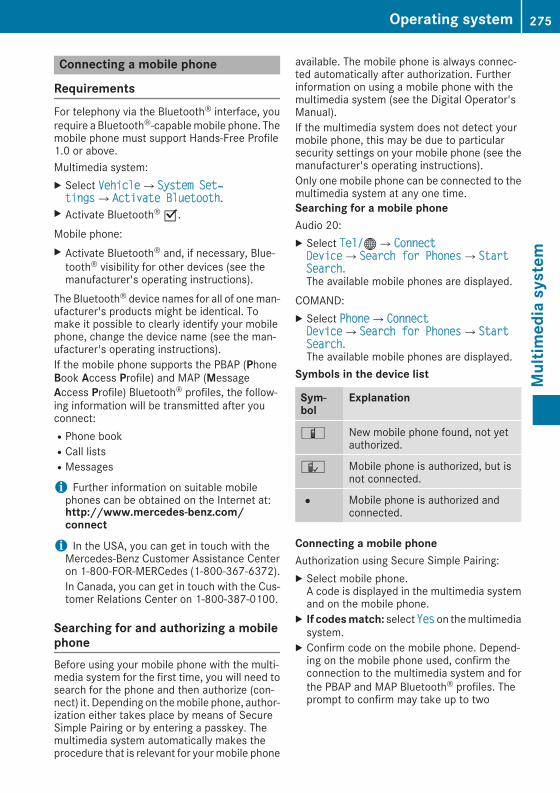
Connecting a mobile phone
RequirementsFor telephony via the Bluetooth® interface, yourequire a Bluetooth®-capablemobile phone. Themobile phone must support Hands-Free Profile1.0 or above.Multimedia system:X Select VehicleQSystem Set‐tingsQActivate Bluetooth.X Activate Bluetooth® O.Mobile phone:X Activate Bluetooth® and, if necessary, Blue-tooth® visibility for other devices (see themanufacturer's operating instructions).
The Bluetooth® device names for all of oneman-ufacturer's products might be identical. Tomake it possible to clearly identify your mobilephone, change the device name (see the man-ufacturer's operating instructions).If the mobile phone supports the PBAP (PhoneBook Access Profile) and MAP (MessageAccess Profile) Bluetooth® profiles, the follow-ing information will be transmitted after youconnect:RPhone bookRCall listsRMessages
i Further information on suitable mobilephones can be obtained on the Internet at:http://www.mercedes-benz.com/connect
i In the USA, you can get in touch with theMercedes-Benz Customer Assistance Centeron 1-800-FOR-MERCedes (1-800-367-6372).In Canada, you can get in touch with the Cus-tomer Relations Center on 1-800-387-0100.
Searching for and authorizing a mobilephoneBefore using your mobile phone with the multi-media system for the first time, you will need tosearch for the phone and then authorize (con-nect) it. Depending on themobile phone, author-ization either takes place by means of SecureSimple Pairing or by entering a passkey. Themultimedia system automatically makes theprocedure that is relevant for yourmobile phone
available. The mobile phone is always connec-ted automatically after authorization. Furtherinformation on using a mobile phone with themultimedia system (see the Digital Operator'sManual).If the multimedia system does not detect yourmobile phone, this may be due to particularsecurity settings on your mobile phone (see themanufacturer's operating instructions).Only one mobile phone can be connected to themultimedia system at any one time.Searching for a mobile phoneAudio 20:X Select Tel/®QConnectDeviceQSearch for PhonesQStartSearch.The available mobile phones are displayed.
COMAND:X Select PhoneQConnectDeviceQSearch for PhonesQStartSearch.The available mobile phones are displayed.
Symbols in the device list
Sym-bol
Explanation
Ï New mobile phone found, not yetauthorized.
Ñ Mobile phone is authorized, but isnot connected.
# Mobile phone is authorized andconnected.
Connecting a mobile phoneAuthorization using Secure Simple Pairing:X Select mobile phone.A code is displayed in the multimedia systemand on the mobile phone.
X If codesmatch: select Yes on themultimediasystem.
X Confirm code on the mobile phone. Depend-ing on the mobile phone used, confirm theconnection to the multimedia system and forthe PBAP and MAP Bluetooth® profiles. Theprompt to confirm may take up to two
Operating system 275
Multim
ediasystem
Z

minutes to be displayed (see the manufactur-er's operating instructions).
X If the codes are different: select No on themultimedia system.The process is canceled.Repeat authorization.
Authorization by entering a passkey (passcode):X Select Bluetooth® name of the mobile phone.The input menu for the passkey is displayed.
X Choose a one to sixteen-digit number combi-nation as a passkey.
X Enter the passkey on the multimedia system.X Press ¬ to confirm.X Enter and confirm the passkey on the mobilephone. Depending on the mobile phone used,confirm the connection to themultimedia sys-tem and for the PBAP and MAP Bluetooth®profiles. The prompt to confirm may take upto two minutes to be displayed (see the man-ufacturer's operating instructions).
Switching between mobile phonesIf you have authorized more than one mobilephone, you can switch between the individualphones.Multimedia system:X Select Connect Device.X Select a mobile phone from the device list.
Media mode
General notesIf you wish to play external media sources, thedefault display must already be turned on. Fur-ther information on media mode (see the DigitalOperator's Manual).The following external media sources can beused:RApple® devices (e.g. iPhone®)RUSB devices (e.g. USB stick, MP3 player)RCDRDVD (COMAND)RSD cardsRvia devices connected by Bluetooth®
Activating media modeMultimedia system:X Select MediaQDevices.The available media sources will be shown.
X Select the media source.Playable files are played.
Inserting and removing an SD card
Important safety notesG WARNINGSD cards are small parts. They can be swal-lowed and cause choking. This poses anincreased risk of injury or even fatal injury.Keep the SD card out of the reach of children.If a SD card is swallowed, seek medical atten-tion immediately.
! If you are no longer using the SD card, youshould remove it and store it outside the vehi-cle. High temperatures can damage the card.
Inserting an SD cardThe SD card slot is located in the stowage com-partment under the armrest.X Insert the SD card into the SD card slot untilthe SD card engages. The side with the con-tacts must face down.
X Select the media source (Y page 276).
Removing an SD cardX Press the SD card.The SD card is ejected.
X Remove the memory card.
Connecting USB devices
276 Operating systemMultim
ediasystem

There are two USB ports in the stowage spaceunder the armrest.X Connect the USB device to the USB port.X Select the media source (Y page 276).
Operating system 277
Multim
ediasystem
Z

Stowage areas
Loading guidelines
G WARNINGCombustion engines emit poisonous exhaustgases such as carbonmonoxide. If the tailgateis open when the engine is running, particu-larly if the vehicle is moving, exhaust fumescould enter the passenger compartment.There is a risk of poisoning.Turn off the engine before opening the tail-gate. Never drive with the tailgate open.
G WARNINGIf objects, luggage or loads are not secured ornot secured sufficiently, they could slip, tipover or be flung around and thereby hit vehicleoccupants. There is a risk of injury, particu-larly in the event of sudden braking or a sud-den change in direction.Always store objects so that they cannot beflung around. Secure objects, luggage orloads against slipping or tipping before thejourney.
G WARNINGThe exhaust tail pipe and tail pipe trim canbecome very hot. If you come into contactwith these parts of the vehicle, you could burnyourself. There is a risk of injury.Always be particularly careful around theexhaust tail pipe and the tail pipe trim. Allowthese components to cool down before touch-ing them.
The handling characteristics of a laden vehicleare dependent on the distribution of the loadwithin the vehicle. For this reason, you shouldobserve the following notes when transporting aload:RNever exceed the maximum permissiblegross vehicle mass or the gross axle weightrating for the vehicle (including occupants).The values are specified on the vehicle iden-tification plate on the B-pillar of the driver'sdoor.RThe cargo compartment is the preferred placeto carry objects.
RPosition heavy loads as far forwards as pos-sible and as low down in the cargo compart-ment as possible.RThe load must not protrude above the upperedge of the seat backrests.RAlways place the load behind unoccupiedseats if possible.RHook in the cargo net when loading.RSecure the load with sufficiently strong andwear-resistant tie-downs. Pad sharp edges forprotection.
Stowage spaces
Important safety notes
G WARNINGIf you transport objects in the vehicle interiorand these are not adequately secured, theycould slip or be flung around and therebystrike vehicle occupants. In addition, cupholders, open stowage spaces and mobilephone brackets may not always be able tohold the objects placed in them in the event ofan accident. There is a risk of injury, particu-larly in the event of sharp braking or suddenchanges of direction.RAlways stow objects in such a way that theycannot be tossed about in these or similarsituations.RAlways make sure that objects do not pro-trude out of the stowage spaces, luggagenets or stowage nets.REnsure that closable stowage spaces areshut before beginning your journey.RAlways stow and secure heavy, hard, poin-ted, sharp-edged, fragile or large objects inthe cargo compartment.
Observe the loading guidelines (Y page 278).
278 Stowage areasStow
ageandfeatures

Stowage compartments in the front
Glove box
X To open: pull handle: and open glove boxflap;.
X To close: fold glove box flap; upwards untilit engages.
Objects in A4 format or an iPad®, for example,can be stored in the glove box. For vehicles witha perfume atomizer (Y page 128) the storagespace of the glove box is restricted.
The glove box can only be locked and unlockedusing the mechanical key (Y page 79).X To lock: insert the mechanical key into thelock and turn it 90° clockwise to position2.
X To unlock: insert the mechanical key into thelock and turn it 90° counter-clockwise toposition1.
Eyeglasses compartment
X To open: press marking:.The eyeglasses compartment opens down.
Make sure that the eyeglasses compartment isalways closed while the vehicle is in motion.
Stowage compartment in the front centerconsole
X Briefly press trim; in the direction of thearrow.Cover: swings up.
Stowage compartment under the armrest
X To open: press button: at front.The stowage space opens.
Stowage areas 279
Stow
ageandfeatures
Z
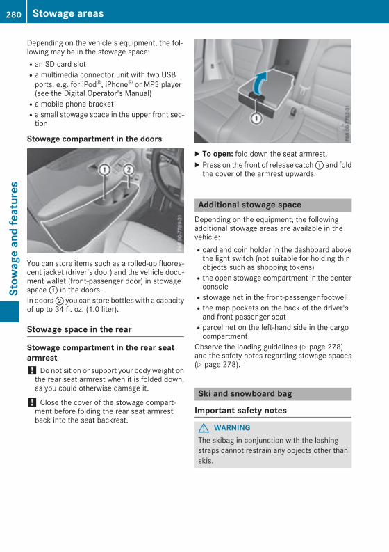
Depending on the vehicle's equipment, the fol-lowing may be in the stowage space:Ran SD card slotRa multimedia connector unit with two USBports, e.g. for iPod®, iPhone® or MP3 player(see the Digital Operator's Manual)Ra mobile phone bracketRa small stowage space in the upper front sec-tion
Stowage compartment in the doors
You can store items such as a rolled-up fluores-cent jacket (driver's door) and the vehicle docu-ment wallet (front-passenger door) in stowagespace: in the doors.In doors; you can store bottles with a capacityof up to 34 fl. oz. (1.0 liter).
Stowage space in the rear
Stowage compartment in the rear seatarmrest! Do not sit on or support your body weight onthe rear seat armrest when it is folded down,as you could otherwise damage it.
! Close the cover of the stowage compart-ment before folding the rear seat armrestback into the seat backrest.
X To open: fold down the seat armrest.X Press on the front of release catch: and foldthe cover of the armrest upwards.
Additional stowage spaceDepending on the equipment, the followingadditional stowage areas are available in thevehicle:Rcard and coin holder in the dashboard abovethe light switch (not suitable for holding thinobjects such as shopping tokens)Rthe open stowage compartment in the centerconsoleRstowage net in the front-passenger footwellRthe map pockets on the back of the driver'sand front-passenger seatRparcel net on the left-hand side in the cargocompartment
Observe the loading guidelines (Y page 278)and the safety notes regarding stowage spaces(Y page 278).
Ski and snowboard bag
Important safety notes
G WARNINGThe skibag in conjunction with the lashingstraps cannot restrain any objects other thanskis.
280 Stowage areasStow
ageandfeatures

Vehicle occupants could be struck in theevent of sudden braking or an accident, forinstance, if you:Rtransport other heavy or sharp-edgedobjects in the skibagRdo not secure the skibag with the lashingstraps
There is a risk of accident and injury.Store only skis in the skibag. Always securethe skibag with the lashing straps so that itcannot move around.
A maximum of four pairs of skis or two snow-boards can be transported in the ski and snow-board bag.
Securing the ski/snowboard bag in thecargo compartment
X Fold the middle rear seat backrest forwards(Y page 281).
X Slide the ski and snowboard bag between thetwo outside rear seat backrests. Ensure thatthe wheels of the ski/snowboard bag are inthe cargo compartment.
X Open the ski/snowboard bag with zip: andplace the skis or snowboards inside it.
X Close the ski and snowboard bag.X Pull tensioning strap; tight by the loose enduntil the skis or snowboards are held firmlyinside the ski/snowboard bag.
X Engage tensioning strap= in a diagonal pat-tern on hooks? in cargo tie-down ringsA asshown.
EASY-PACKQuickfold rear bench seat
Important safety notes
G WARNINGIf the rear bench seat/rear seat and seatbackrest are not engaged they could fold for-wards, e.g. when braking suddenly or in theevent of an accident.RThe vehicle occupant would thereby bepushed into the seat belt by the rear benchseat/rear seat or by the seat backrest. Theseat belt can no longer offer the intendedlevel of protection and could even causeinjuries.RObjects or loads in the trunk/cargo com-partment cannot be restrained by the seatbackrest.
There is an increased risk of injury.Before every trip, make sure that the seatbackrests and the rear bench seat/rear seatare engaged.
! When folding the rear seat backrest for-wards, ensure that there are no items lying onthe seat cushions. These items could other-wise be damaged or could themselves dam-age the rear seats.
Observe the loading guidelines (Y page 278).The outside and the middle rear seat backrestscan be folded down separately to increase thecargo compartment capacity. The division ratiois 40/20/40.
Stowage areas 281
Stow
ageandfeatures
Z

Both outside seat backrests in the rear com-partment are electrically unlocked with therelease handles either in the cargo compart-ment or beside the seat backrests in the rearcompartment (vehicleswith EASY-PACK tailgateonly). The corresponding rear seat backreststhen fold forward automatically.
Folding the rear seat backrests forward
PreparationX Vehicles without memory function: if neces-sary, move the driver's or front-passengerseat forward.
X Vehicles with memory function: when one orboth parts of the rear seat backrest are foldedforward, the respective front seat movesforward slightly, when necessary, in order toavoid contact.When the engine is running, the driver's seatdoes not move forward.
X Fully insert the rear seat backrest headrestraints.
X Hook seat belt buckle tongue: through seatbelt retainer;.
Release handle in the cargo compartment
X Pull the left or right release handle:.The corresponding backrest folds forward.
X Move the driver's or front-passenger seatback if necessary.
Release handle next to the seat backrestThe release handle beside the seat backrest isonly present in vehicles with an EASY-PACK tail-gate.
X Pull the left or right release handle: besidethe seat backrests.The corresponding backrest folds forward.
X Move the driver's or front-passenger seatback if necessary.
Middle rear seat backrest
X Pull release lever; forward.Rear seat backrest: is released.
X Fold rear seat backrest: forward.X Move the driver's or front-passenger seatback if necessary.
Folding the rear seat backrest back! Make sure that the seat belt does notbecome trapped when folding the rear seatbackrest back. Otherwise, it could be dam-aged.
282 Stowage areasStow
ageandfeatures

Left and right seat backrest:X Move the driver's or front-passenger seatforward if necessary.
X Fold rear seat backrest: back until itengages.If the rear seat backrest is not engaged andlocked, this will be shown in the multifunctiondisplay in the instrument cluster. A warningtone also sounds.
X Adjust the head restraints if necessary(Y page 101).
X Move the driver's or front-passenger seatback if necessary.
Middle rear seat backrest:X Move the driver's or front-passenger seatforward if necessary.
X Fold seat backrest: back until it engages.Red lock status indicator; is no longer visi-ble.
X Adjust the head restraints if necessary(Y page 101).
X Move the driver's or front-passenger seatback if necessary.
Locking the center rear seat backrest
In order to prevent the cargo compartment frombeing accessed by unauthorized persons, thecenter seat backrest can be locked using acatch. The center seat backrest can only be fol-ded forward together with the left seat backrest.X To lock: fold the left and center seat backr-ests forward. Make sure that the center andleft seat backrests are engaged and joinedtogether.
X Slide catch: upwards.The release mechanism of the center seatbackrest is locked.
X Tounlock: fold the left and center seat backr-ests forward.
X Slide catch: downwards.
Adjusting the angle of the rear seatbackrests (cargo position)
Stowage areas 283
Stow
ageandfeatures
Z

Vehicles with the stowage space package: toenlarge the cargo compartment, you can adjustthe rear seat backrests to a 10 degrees steeperangle (cargo position).X Fold the seat backrest forward (Y page 281).X Move handle: in the direction of the arrow.X Push back seat backrest; as far as han-dle: until the backrest engages.The cargo position has been reached.
Securing loads
Cargo tie-down ringsObserve the following notes on securing loads:RObserve the loading guidelines (Y page 278).RSecure the load using the cargo tie-downrings.RDistribute the load on the cargo tie-downrings evenly.RDo not use elastic straps or nets to secure aload, as these are only intended as an anti-slipprotection for light loads.RDo not route tie-downs across sharp edges orcorners.RPad sharp edges for protection.
: Cargo tie-down rings in the rear-compart-ment footwell (vehicles with cargo net)
: Cargo tie-down rings in the cargo compart-ment
Bag hook
G WARNINGThe bag hooks cannot restrain heavy objectsor items of luggage. Objects or items of lug-gage could be flung around and thereby hitvehicle occupants when braking or abruptlychanging directions. There is a risk of injury.Only hang light objects on the bag hooks.Never hang hard, sharp-edged or fragileobjects on the bag hooks.
! The bag hook can bear a maximum load of6.6lbs (3kg) and should not be used to securea load.
: Bag hook
284 Stowage areasStow
ageandfeatures
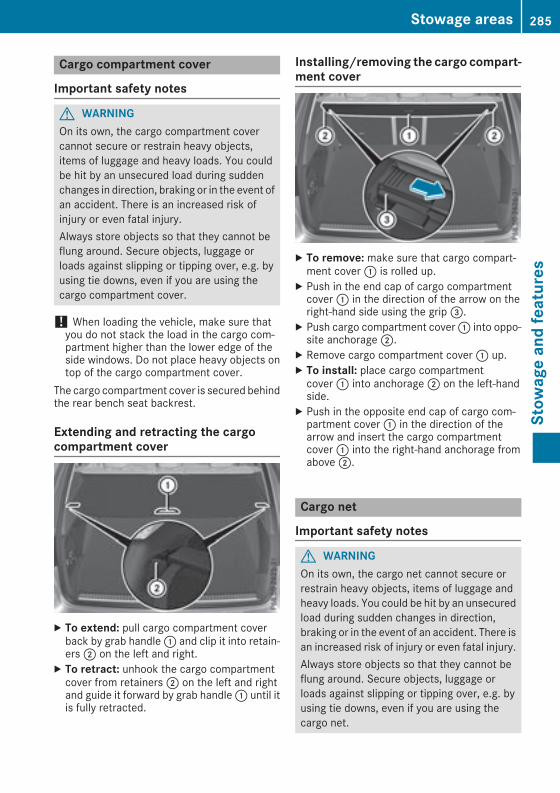
Cargo compartment cover
Important safety notes
G WARNINGOn its own, the cargo compartment covercannot secure or restrain heavy objects,items of luggage and heavy loads. You couldbe hit by an unsecured load during suddenchanges in direction, braking or in the event ofan accident. There is an increased risk ofinjury or even fatal injury.Always store objects so that they cannot beflung around. Secure objects, luggage orloads against slipping or tipping over, e.g. byusing tie downs, even if you are using thecargo compartment cover.
! When loading the vehicle, make sure thatyou do not stack the load in the cargo com-partment higher than the lower edge of theside windows. Do not place heavy objects ontop of the cargo compartment cover.
The cargo compartment cover is secured behindthe rear bench seat backrest.
Extending and retracting the cargocompartment cover
X To extend: pull cargo compartment coverback by grab handle: and clip it into retain-ers; on the left and right.
X To retract: unhook the cargo compartmentcover from retainers; on the left and rightand guide it forward by grab handle: until itis fully retracted.
Installing/removing the cargo compart-ment cover
X To remove: make sure that cargo compart-ment cover: is rolled up.
X Push in the end cap of cargo compartmentcover: in the direction of the arrow on theright-hand side using the grip=.
X Push cargo compartment cover: into oppo-site anchorage;.
X Remove cargo compartment cover: up.X To install: place cargo compartmentcover: into anchorage; on the left-handside.
X Push in the opposite end cap of cargo com-partment cover: in the direction of thearrow and insert the cargo compartmentcover: into the right-hand anchorage fromabove;.
Cargo net
Important safety notes
G WARNINGOn its own, the cargo net cannot secure orrestrain heavy objects, items of luggage andheavy loads. You could be hit by an unsecuredload during sudden changes in direction,braking or in the event of an accident. There isan increased risk of injury or even fatal injury.Always store objects so that they cannot beflung around. Secure objects, luggage orloads against slipping or tipping over, e.g. byusing tie downs, even if you are using thecargo net.
Stowage areas 285
Stow
ageandfeatures
Z

It is important to use a cargo net if you load thevehicle with small objects above the seat backr-ests. For safety reasons, always use a cargo netwhen transporting loads.Damaged cargo nets can no longer fulfill theirprotective function andmust be replaced. Visit aqualified specialist workshop.
Using the cargo net
Preparing the cargo net
The cargo net can be used in two different posi-tions (behind the B-pillar or the C-pillar):RThe brackets behind B-pillar: are requiredfor the cargo compartment enlargement(Y page 281).The corresponding cargo tie-down rings totighten the net are located in the footwell ofthe rear bench seat (Y page 284).RThe brackets behind C‑pillar; are requiredfor the cargo compartment behind the rearbench seat.The corresponding cargo tie-down rings totension the net are located in the cargo com-partment (Y page 284).
The cargo net is located in the stowage spaceunder the cargo compartment floor.X Open both Velcro fasteners and remove thecargo net.
X Unroll and unfold the cargo net.The upper and lower guide rods must engageaudibly.
Attaching and tightening the cargo net
Cargo net installed behind the C-pillarX To attach and tighten: insert guide rod:into bracket; and slide forward.
X Attach belt hook? to the cargo tie-down ringand pull down on the loose end of the lashingstrap until the cargo net is taut.
X After driving a short distance, check the ten-sion of the cargo net and retighten it if nec-essary.
X To release and detach: pull the belt clamp= up.
X Unhook belt hook? from the cargo tie-downring.
X Detach guide rod: from bracket;.
Storing the cargo netX Press the red button on the upper and lowerguide rods.
X Fold the cargo net and roll it up.X Close the two Velcro fasteners on the cargonet holder.
X Put the cargo net in the stowage space underthe cargo compartment floor.
Parcel net
Important safety notes
G WARNINGIf you transport objects in the vehicle interiorand these are not adequately secured, theycould slip or be flung around and therebystrike vehicle occupants. In addition, cupholders, open stowage spaces and mobilephone brackets may not always be able tohold the objects placed in them in the event of
286 Stowage areasStow
ageandfeatures

an accident. There is a risk of injury, particu-larly in the event of sharp braking or suddenchanges of direction.RAlways stow objects in such a way that theycannot be tossed about in these or similarsituations.RAlways make sure that objects do not pro-trude out of the stowage spaces, luggagenets or stowage nets.REnsure that closable stowage spaces areshut before beginning your journey.RAlways stow and secure heavy, hard, poin-ted, sharp-edged, fragile or large objects inthe cargo compartment.
Observe the following notes:RObserve the loading guidelines (Y page 278).RTo avoid damaging the side trim panels in thecargo compartment, maintain a sufficient dis-tance from the side trim panels in the cargocompartment when removing and insertingthe cargo compartment floor.
Installing the parcel net
X Open cargo compartment floor;(Y page 288), raise by approximately 45° andremove to the rear.
X Place cargo compartment floor; on a cleansurface.
X Stretch parcel net: over cargo compart-ment floor; as shown.
Make sure that:Rparcel net: is aligned with the center ofcargo compartment floor;Rrubber band= is below mountings?RtabA is facing forward
X Slide cargo compartment floor; horizon-tally into the cargo compartment until mount-ings? are positioned in guidesE on bothsides.
X Raise cargo compartment floor; by approx-imately 45° so that mountings? engageaudibly.
Make sure that:Rrubber bandC is below claspB. The rubberband must not block the clasp.Rrubber band= is below baseD.X Fold cargo compartment floor; down andpress down until it engages.
Coat hooks on the tailgate
: Coat hook
Cargo compartment plug-in module(telescope bars)
General notesThe cargo compartment plug-in module allowsyou to use your cargo compartment for a varietyof purposes.
Stowage areas 287
Stow
ageandfeatures
Z

The following accessory parts are located underthe cargo compartment floor:Ra telescopic rodRtwo mounting elementsRtwo brackets
Important safety notes
G WARNINGIf you drivewhen the cargo compartment flooris open, objects could be flung around, thusstriking vehicle occupants. There is a risk ofinjury, particularly in the event of suddenbraking or a sudden change in direction.Always close the cargo compartment floorbefore a journey.
Installation
X Open cargo compartment floor;(Y page 288).
X Attach brackets: in the desired position onthe side of cargo compartment floor;.
X Close cargo compartment floor;.
X Turn mounting elements= to =.X Insert mounting elements= into brack-ets:.
X Pull telescopic rod? apart.X Insert telescopic rod? into mounting ele-ments=.
X Turn bothmounting elements= to& untilyou feel them engage.
Stowage well under the cargo com-partment floor
Important safety notes
G WARNINGIf you drivewhen the cargo compartment flooris open, objects could be flung around, thusstriking vehicle occupants. There is a risk ofinjury, particularly in the event of suddenbraking or a sudden change in direction.Always close the cargo compartment floorbefore a journey.
The following items are located beneath thecargo compartment floor:Rthe folding boxRtire-change tool kitRthe TIREFITRthe EASY-PACK load-securing kit
Opening/closing the cargo compart-ment floor
X To open: open the tailgate.X Holding ribbing;, press handle: down.Handle: folds up.
288 Stowage areasStow
ageandfeatures

X Fold out hook= on the underside of thecargo compartment floor in the direction ofthe arrow.
X Attach hook= to the cargo compartment'supper seal?.
X To close: detach hook= from the cargocompartment's upper seal?.
X Fasten hook= to the bracket on the under-side of the cargo compartment floor.
X Fold the cargo compartment floor down.X Press the cargo compartment floor down untilit engages.
Locking/unlocking the cargo compart-ment floor
1 Cargo compartment floor unlocked2 Cargo compartment floor lockedThe cargo compartment floor can be locked andunlocked using the mechanical key.
Roof carrier
Important safety notes
G WARNINGWhen you load the roof, the center of gravityof the vehicle rises and the driving character-istics change. If you exceed themaximum roofload, the driving characteristics, as well assteering and braking, will be greatly impaired.There is a risk of an accident.Never exceed the maximum roof load andadjust your driving style.
You will find information on the maximum roofload in the "Technical data" section(Y page 370).
! Mercedes-Benz recommends that you onlyuse roof carriers that have been tested andapproved for Mercedes-Benz vehicles. Thishelps to avoid damage to the vehicle.Position the load on the roof carrier in such away that the vehicle will not sustain damageeven when it is in motion.Depending on the vehicle equipment, ensurethat when the roof carrier is installed you can:Rfully raise the sliding sunroof/panoramaroof with power tilt/sliding panelRopen the tailgate fully
Stowage areas 289
Stow
ageandfeatures
Z

An incorrectly secured roof carrier or roof loadmay become detached from the vehicle. Youmust therefore ensure that you observe the roofcarrier manufacturer's installation instructions.Vehicles with a panorama roof with powertilt/sliding panel: the panorama roof withpower tilt/sliding panel cannot be opened if aroof carrier is installed. The panorama roof withpower tilt/sliding panel can still be raised toallow ventilation of the vehicle interior. If thepanorama roof with power tilt/sliding panelmakes contact with a roof carrier approved byMercedes-Benz, the sunroof will lower slightlybut remain raised at the rear.
Attaching the roof carrierX Secure the roof carrier to the roof rails.X Observe the manufacturer's installationinstructions.
Features
Cup holder
Important safety notes
G WARNINGIf you transport objects in the vehicle interiorand these are not adequately secured, theycould slip or be flung around and therebystrike vehicle occupants. In addition, cupholders, open stowage spaces and mobilephone brackets may not always be able tohold the objects placed in them in the event ofan accident. There is a risk of injury, particu-larly in the event of sharp braking or suddenchanges of direction.RAlways stow objects in such a way that theycannot be tossed about in these or similarsituations.RAlways make sure that objects do not pro-trude out of the stowage spaces, luggagenets or stowage nets.REnsure that closable stowage spaces areshut before beginning your journey.RAlways stow and secure heavy, hard, poin-ted, sharp-edged, fragile or large objects inthe cargo compartment.
! Only use the cup holders for containers ofthe right size and which have lids. The drinkscould otherwise spill.
! Do not expose drinks bottles in the cupholder in the center console to continuous,strong and direct sunlight. The passengercompartment in the area of the center con-sole can otherwise be damaged by the con-centrated and reflected sunlight.
Observe the loading guidelines (Y page 278).
Cup holder in the front center console
X To open: open the stowage compartment(Y page 279).
X To remove: slide catch= forward and pullout cup holder;.
X To insert: insert cup holder; and slide backcatch=.
X To close: push cover: of the stowage com-partment closed.
If you remove the cup holder insert, you can usethe resulting compartment for stowage.You can remove the cup holder's rubber mat forcleaning. Cleanwith clear, lukewarmwater only.
Cup holder in the rear seat armrest! Do not sit on or support your body weight onthe rear seat armrest when it is folded down,as you could otherwise damage it.
! Close the cup holder before folding the rearseat armrest up. Otherwise, the cup holdercould be damaged.
290 FeaturesStow
ageandfeatures

X Fold down the rear seat armrest.X To open: press the front of cup holder:or;.Cup holder: or; extends automatically.
X To fold out: place a container in the cupholder.The cup holder: or; folds down automat-ically.
X To fold in: remove the container.The cup holder: or; folds in automati-cally.
X To close: slide cup holder: or; back untilit engages.
Sun visors
Overview
G WARNINGIf themirror cover of the vanitymirror is foldedup when the vehicle is in motion, you could beblinded by incident light. There is a risk of anaccident.Always keep the mirror cover folded downwhile driving.
: Mirror light; Bracket= Retaining clip, e.g. for a car park ticket? Vanity mirrorA Mirror cover
Vanity mirror in the sun visorMirror light: only functions if the sun visor isclipped into bracket; and mirror coverA hasbeen folded up.
Glare from the side
X Fold down the sun visor.X Pull sun visor: out of retainer;.X Swing sun visor: to the side.X Slide sun visor: horizontally as required.
Rear side window roller sunblinds! Always guide the roller sunblind by hand. Donot let it snap back suddenly as this woulddamage the automatic roller mechanism.
! Do not drive the vehicle with the roller sun-blind hooked in and the side windows openedsimultaneously. The roller sunblind can jump
Features 291
Stow
ageandfeatures
Z

out of the retainers and spring back suddenlywhen driving at high speeds, e.g. when drivingon the freeway. This could damage the inertiareel. Therefore, either close the side windowor retract the roller sunblind before driving athigh speeds.
X To extend: pull the roller sunblind out bytab: and hook it onto retainers; at the topof the window.
Ashtray
Front ashtray! The stowage space under the ashtray is notheat resistant. Before placing lit cigarettes inthe ashtray, make sure that the ashtray isproperly engaged. Otherwise, the stowagespace could be damaged.
X To open: open the stowage compartment(Y page 279).
X Push the cover of the ashtray upwards at itsright side=.
X To remove the insert: hold the sides ofinsert?, push it forward and lift it up; andout.
X To install the insert: press insert? into theholder until it engages.
X To close: close the cover of the ashtray.X Push cover: of the stowage compartmentclosed.
i You can remove the ashtray insert and usethe resulting compartment for stowage.
Rear compartment ashtray
X To open: pull cover; out by its top edge.X To remove the insert: push ribbing= fromthe left side and pull insert: upwards.
X To install the insert: install insert: fromabove into the holder and press down into theholder until it engages.
Cigarette lighter
G WARNINGYou can burn yourself if you touch the hotheating element or the socket of the cigarettelighter.In addition, flammable materials can ignite if:Rthe hot cigarette lighter fallsRa child holds the hot cigarette lighter toobjects, for example
There is a risk of fire and injury.Always hold the cigarette lighter by the knob.Always make sure that the cigarette lighter isout of reach of children. Never leave childrenunsupervised in the vehicle.
Your attention must always be focused on thetraffic conditions. Only use the cigarette lighterwhen road and traffic conditions permit.
292 FeaturesStow
ageandfeatures

Cigarette lighter (example)X Turn the SmartKey to position2 in the igni-tion lock (Y page 132).
X To open: open the stowage compartment(Y page 279).
X Press in cigarette lighter;.Cigarette lighter;will pop out automaticallywhen the heating element is red-hot.
X To close: push cover: of the stowage com-partment closed.
12 V sockets
General notesX Turn the SmartKey to position1 in the igni-tion lock (Y page 132).
The sockets can be used for accessories with amaximum draw of 180 W (15 A). Accessoriesinclude such items as chargers for mobilephones.If you use the sockets for long periods when theengine is switched off, the battery may dis-charge.An emergency cut-out ensures that the on-board voltage does not drop too low. If the on-board voltage is too low, the power to the sock-ets is automatically cut. This ensures that thereis sufficient power to start the engine.If you have connected a device to the 12 Vsocket, leave the cover of the stowage com-partment open. This prevents the cover frombeing blocked.
Socket in the front center console
12 V socket (example)X To open: open the stowage compartment(Y page 279).
X Lift up the cover of socket;.X To close: push cover: of the stowage com-partment closed.
Socket in the rear compartment centerconsole
X Pull cover; out by its top edge.X Lift up the cover of socket:.
Socket in the cargo compartment
Features 293
Stow
ageandfeatures
Z

X Lift up the cover of socket:.
115 V socket
Important safety notes
G DANGERWhen a suitable device is connected, the115 V power socket will be carrying a highvoltage. You could receive an electric shock ifthe connector cable or the 115 V powersocket is pulled out of the trim or is damagedor wet. There is a risk of fatal injury.RUse only connector cables that are dry andfree of damage.RWhen the ignition is off, make sure that the115 V power socket is dry.RHave the 115 V power socket checked orreplaced immediately at a qualified speci-alizedworkshop if it is damagedor has beenpulled out of the trim.RNever plug the connector cable into a 115Vpower socket that is damaged or has beenpulled out of the trim.
G DANGERIf you reach into the power socket or pluginappropriate devices into the power socket,you could receive an electric shock. There is arisk of fatal injury.Only connect appropriate devices to thepower socket.
! Note that work and repairs on the 115 Vpower socket should only be carried out byqualified specialist personnel.
General notesThe 115 V power socket provides an alternatingvoltage of 115 V so that small electronic devices
can be connected. These devices, such asgames consoles, chargers and laptops,must notconsume more than a maximum of 150 wattsaltogether.Requirements for operation of these devices:Rthe electronic device that you connect has asuitable connector and conforms to stand-ards specific to the country you are in.Rthe plug of the electronic device is pluggedcorrectly into 115 V power socket.Rthe maximum wattage of the device to beconnected must not exceed 150 watts.Rthe on-board power supply is within a permis-sible voltage range.Rthe 12 V sockets in the rear compartment andthe cargo compartment are operational.
Using the 115 V power socket
X To switch on: switch the ignition on.X Open flap=.X Insert the plug of the electronic device into115 V power socket:.Indicator lamp; lights up.
X To switch off: disconnect the plug from115 V power socket:.Ensure that you do not pull on the cord.
294 FeaturesStow
ageandfeatures

Problems with the 115 V power socket
Problem Possible causes/consequences andM Solutions
The warning lamp on the115 V power socket isnot lit.
The on-board voltage is too low because the battery is too weak.X Start the engine.orX Charge the battery (Y page 327).If the indicator lamp still does not light up:X Visit a qualified specialist workshop.
The temperature of the DC/AC converter is temporarily too high.X Remove the electronic device connector from the 115 V socket.X Let the DC/AC converter cool down.If the indicator lamp still does not light up after cooling down theconverter:X Visit a qualified specialist workshop.
You have connected an electronic device that has a constant nominalpower of less than 150 watts, but has a very high switch-on current.This device will not work. If you connect such a device, the 115 Vpower socket will not supply it with power.X Connect a suitable electronic device.
mbrace
General notesThe mbrace system is only available in the USA.You must have a license agreement to activatethembrace service. Make sure that your systemis activated and operational. To register, pressthe ï Info call button. If any of the stepsmentioned are not carried out, the system maynot be activated.If you have questions about the activation, con-tact one of the following telephone hotlines:Mercedes-Benz Customer Assistance Center at1-800-FOR-MERCedes (1-800-367-6372) or1-866-990-9007Shortly after successfully registering with thembrace service, a user ID and password will besent to you by mail. You can use this passwordto log onto the mbrace area under "OwnersOnline" at http://www.mbusa.com.
The system is available if:Rit has been activated and is operationalRthe corresponding mobile phone network isavailable for transmitting data to the Cus-tomer CenterRa service subscription is availableDetermining the location of the vehicle on amapis only possible if:RGPS reception is availableRthe vehicle position can be forwarded to theCustomer Assistance Center
The mbrace systemTo adjust the volume during a call, proceed asfollows:X Press theW orX button on the multi-function steering wheel.
orX Use the multimedia system volume control.
Features 295
Stow
ageandfeatures
Z
The system offers various services, e.g.:RAutomatic and manual emergency callRRoadside Assistance callRInfo callYou can find information and a description of allavailable features under "Owners Online" athttp://www.mbusa.com.
System self-testAfter you have switched on the ignition, the sys-tem carries out a self-diagnosis.A malfunction in the system has been detectedif one of the following occurs:RThe indicator lamp in the SOS button does notcome on during the system self-test.RThe indicator lamp in the F RoadsideAssistance button does not light up duringself-diagnosis of the system.RThe indicator lamp in theï Info call buttondoes not light up during the system self-diag-nosisRThe indicator lamp in one or more of the fol-lowing buttons continues to light up red afterthe system self-diagnosis:- SOS button- F Roadside Assistance call button- Info call buttonïRafter the system self-diagnosis, the Inoper‐ative or Service Not Activatedmessageappears in the multifunction display.
If a malfunction is indicated as outlined above,the system may not operate as expected. In theevent of an emergency, help will have to besummoned by other means.Have the system checked at the nearestMercedes-Benz Service Center or contact thefollowing service hotlines:Mercedes-Benz Customer Assistance Center at1-800-FOR-MERCedes (1-800-367-6372) or1-866-990-9007
Emergency call
Important safety notesG WARNINGIt can be dangerous to remain in the vehicle,even if you have pressed the SOS button in anemergency if:Ryou see smoke inside or outside of the vehi-cle, e.g. if there is a fire after an accidentRthe vehicle is on a dangerous section ofroadRthe vehicle is not visible or cannot easily beseen by other road users, particularly whendark or in poor visibility conditions
There is a risk of an accident and injury.Leave the vehicle immediately in this or simi-lar situations as soon as it is safe to do so.Move to a safe location along with other vehi-cle occupants. In such situations, secure thevehicle in accordance with national regula-tions, e. g. with a warning triangle.
General notesObserve the notes on system activation(Y page 295).An emergency call is dialed automatically if anair bag or Emergency Tensioning Device is trig-gered. You cannot end an automatically trig-gered emergency call yourself.An emergency call can also be initiated man-ually.As soon as the emergency call has been initi-ated, the indicator lamp in the SOS buttonflashes. The Connecting Call messageappears in the multifunction display.The audio output is muted.Once the connection has been made, the CallConnected message appears in the multifunc-tion display.All important information on the emergency istransmitted, for example:RCurrent location of the vehicle (as determinedby the GPS system)RVehicle identification numberRInformation on the severity of the accidentShortly after the emergency call has been initi-ated, a voice connection is automatically estab-
296 FeaturesStow
ageandfeatures
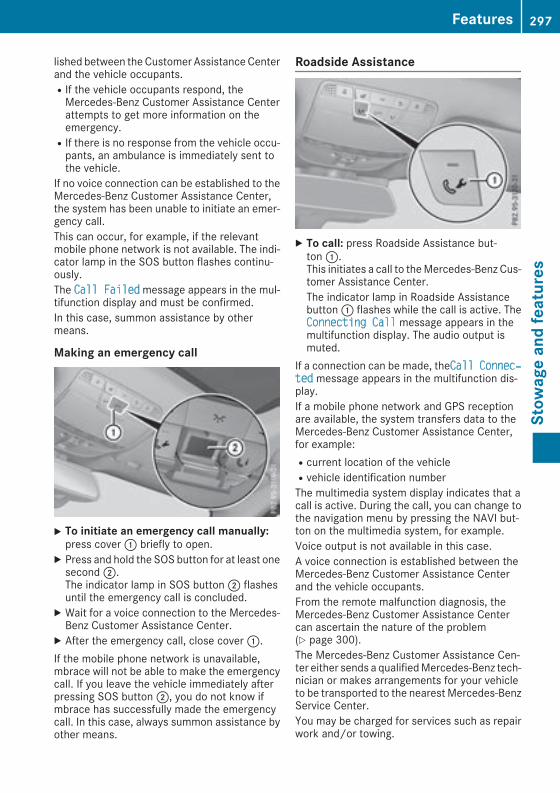
lished between theCustomer AssistanceCenterand the vehicle occupants.RIf the vehicle occupants respond, theMercedes-Benz Customer Assistance Centerattempts to get more information on theemergency.RIf there is no response from the vehicle occu-pants, an ambulance is immediately sent tothe vehicle.
If no voice connection can be established to theMercedes-Benz Customer Assistance Center,the system has been unable to initiate an emer-gency call.This can occur, for example, if the relevantmobile phone network is not available. The indi-cator lamp in the SOS button flashes continu-ously.The Call Failedmessage appears in the mul-tifunction display and must be confirmed.In this case, summon assistance by othermeans.
Making an emergency call
X To initiate an emergency call manually:press cover: briefly to open.
X Press and hold the SOS button for at least onesecond;.The indicator lamp in SOS button; flashesuntil the emergency call is concluded.
X Wait for a voice connection to the Mercedes-Benz Customer Assistance Center.
X After the emergency call, close cover:.If the mobile phone network is unavailable,mbrace will not be able to make the emergencycall. If you leave the vehicle immediately afterpressing SOS button;, you do not know ifmbrace has successfully made the emergencycall. In this case, always summon assistance byother means.
Roadside Assistance
X To call: press Roadside Assistance but-ton:.This initiates a call to theMercedes-Benz Cus-tomer Assistance Center.The indicator lamp in Roadside Assistancebutton: flashes while the call is active. TheConnecting Call message appears in themultifunction display. The audio output ismuted.
If a connection can be made, theCall Connec‐ted message appears in the multifunction dis-play.If a mobile phone network and GPS receptionare available, the system transfers data to theMercedes-Benz Customer Assistance Center,for example:Rcurrent location of the vehicleRvehicle identification numberThe multimedia system display indicates that acall is active. During the call, you can change tothe navigation menu by pressing the NAVI but-ton on the multimedia system, for example.Voice output is not available in this case.A voice connection is established between theMercedes-Benz Customer Assistance Centerand the vehicle occupants.From the remote malfunction diagnosis, theMercedes-Benz Customer Assistance Centercan ascertain the nature of the problem(Y page 300).The Mercedes-Benz Customer Assistance Cen-ter either sends a qualifiedMercedes-Benz tech-nician or makes arrangements for your vehicleto be transported to the nearest Mercedes-BenzService Center.You may be charged for services such as repairwork and/or towing.
Features 297
Stow
ageandfeatures
Z
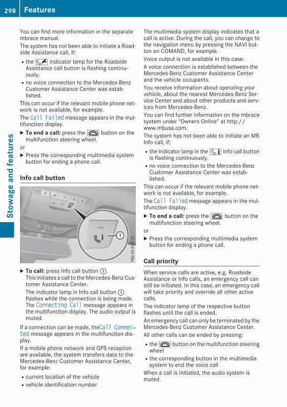
You can find more information in the separatembrace manual.The system has not been able to initiate a Road-side Assistance call, if:Rthe F indicator lamp for the RoadsideAssistance call button is flashing continu-ously.Rno voice connection to the Mercedes-BenzCustomer Assistance Center was estab-lished.
This can occur if the relevant mobile phone net-work is not available, for example.The Call Failedmessage appears in the mul-tifunction display.X To end a call: press the~ button on themultifunction steering wheel.
orX Press the corresponding multimedia systembutton for ending a phone call.
Info call button
X To call: press Info call button:.This initiates a call to theMercedes-Benz Cus-tomer Assistance Center.The indicator lamp in Info call button:flashes while the connection is being made.The Connecting Call message appears inthe multifunction display. The audio output ismuted.
If a connection can be made, theCall Connec‐ted message appears in the multifunction dis-play.If a mobile phone network and GPS receptionare available, the system transfers data to theMercedes-Benz Customer Assistance Center,for example:Rcurrent location of the vehicleRvehicle identification number
The multimedia system display indicates that acall is active. During the call, you can change tothe navigation menu by pressing the NAVI but-ton on COMAND, for example.Voice output is not available in this case.A voice connection is established between theMercedes-Benz Customer Assistance Centerand the vehicle occupants.You receive information about operating yourvehicle, about the nearest Mercedes-Benz Ser-vice Center and about other products and serv-ices from Mercedes-Benz.You can find further information on the mbracesystem under "Owners Online" at http://www.mbusa.com.The system has not been able to initiate an MBInfo call, if:Rthe indicator lamp in the ï Info call buttonis flashing continuously.Rno voice connection to the Mercedes-BenzCustomer Assistance Center was estab-lished.
This can occur if the relevant mobile phone net-work is not available, for example.The Call Failedmessage appears in the mul-tifunction display.X To end a call: press the~ button on themultifunction steering wheel.
orX Press the corresponding multimedia systembutton for ending a phone call.
Call priorityWhen service calls are active, e.g. RoadsideAssistance or Info calls, an emergency call canstill be initiated. In this case, an emergency callwill take priority and override all other activecalls.The indicator lamp of the respective buttonflashes until the call is ended.An emergency call can only be terminated by theMercedes-Benz Customer Assistance Center.All other calls can be ended by pressing:Rthe~ button on themultifunction steeringwheelRthe corresponding button in the multimediasystem to end the voice call
When a call is initiated, the audio system ismuted.
298 FeaturesStow
ageandfeatures

The mobile phone is no longer connected to themultimedia system.However, if you want to use your mobile phone,do so only when the vehicle is stationary and ina safe location.
Downloading destinations
Downloading destinationsDownloading destinations gives you access to adatabase with over 15 million points of interest(POIs). These can be downloaded on the navi-gation system in your vehicle. If you know thedestination, the address can be downloaded.Alternatively, you can obtain the location ofPoints of Interest (POIs)/important destinationsin the vicinity.Furthermore, you can download routes with upto four way points.You are prompted to confirm route guidance tothe address entered.X SelectYes by turning3 or sliding1the controller and confirm with7.The system calculates the route and subse-quently starts the route guidance with theaddress entered.If you select No the address can be stored inthe address book.
The destination download function is availableif:Rthe vehicle is equipped with a navigation sys-tem.Rthe relevant mobile phone network is availa-ble and data transfer is possible.
Route AssistanceThis service is part of thembrace PLUS Packageand cannot be purchased separately.You can use the Route Assistance function evenif the vehicle is not equipped with a navigationsystem.Within the framework of this service, you receivea professional and reliable form of navigationsupport without having to leave your vehicle.The customer service representative finds asuitable route depending on your vehicle's cur-rent position and the desired destination. Youwill then be guided live through the current routesection.
Search & Send
General notesTo use "Search & Send", your vehicle must beequipped with mbrace and a navigation system.Additionally, an mbrace service subscriptionmust be completed."Search & Send" is a destination entry service. Adestination address which is found on GoogleMaps® can be transferred via mbrace directly toyour vehicle's navigation system.
Specifying and sending the destinationaddressX Go to the website http://maps.google.comand enter a destination address into the entryfield.
X To send the destination address to the e-mail address of your mbrace account:click on the corresponding button on theweb-site.Example:If you select 'Send to vehicle' and then'Mercedes-Benz', the destination address willbe sent to your vehicle.
X When the "Send" dialog window appears:Enter the e-mail address you specified whensetting up your mbrace account into the cor-responding field.
X Click "Send".Information on specific commands such as"Address entry" or "Send" can be found on thewebsite.
Calling up a transmitted destinationaddressX Turn the SmartKey to position2 in the ignitionlock (Y page 132).The transmitted destination address is loadedinto the vehicle's navigation system.A display message appears, asking whethernavigation should be started.
X SelectYes by turning3 or sliding1the controller and confirm with7.The system calculates the route and subse-quently starts the route guidance with theaddress entered.If you select No the address can be stored inthe address book.
Features 299
Stow
ageandfeatures
Z
If you have sent more than one destinationaddress, each individual destination must beconfirmed separately.
Destination addresses are loaded in the sameorder as the order in which they were sent.If you ownmultipleMercedes-Benz vehicleswithmbrace and activated mbrace accounts:If multiple vehicles are registered under thesame e-mail address, the destination will besent to all the vehicles.
Vehicle remote openingYou can use the vehicle remote opening if youhave unintentionally locked your vehicle and areplacement SmartKey is not available.The vehicle can be opened by the Mercedes-Benz Customer Assistance Center.The vehicle can be immediately openedremotely within four days of the ignition beingturned off. After this time, the remote unlockingmay be delayed by 15 to 60 minutes. After30 days, the vehicle can no longer be openedremotely.The vehicle remote unlocking feature is availa-ble if the relevant mobile phone network is avail-able and a data connection is possible.X Contact the following service hotlines:Mercedes-Benz Customer Assistance Centerat 1-800-FOR-MERCedes (1-800-367-6372)or 1-866-990-9007You will be asked for your password.
X Return to your vehicle at the time agreed uponwith the Mercedes-Benz Customer Assis-tance Center.
Alternatively, the vehicle can be opened via:Rthe Internet, under the "Owners Online" sec-tionRtelephone applications (e.g. for iPhone®,Android™)
To do this, you will need your identification num-ber and password.
Vehicle remote closingThe vehicle remote-closing feature can be usedwhen you have forgotten to lock the vehicle andyou are no longer nearby.The vehicle can then be locked by theMercedes-Benz Customer Assistance Center.
The vehicle can be immediately remotely lockedwithin four days of the ignition being turned off.After this time, remote closing may be delayedby 15 to 60 minutes. After 30 days the vehiclecan no longer be valet locked remotely.The vehicle remote closing feature is available ifthe relevant mobile phone network is availableand a data connection is possible.X Contact the following service hotlines:Mercedes-Benz Customer Assistance Centerat 1-800-FOR-MERCedes (1-800-367-6372)or 1-866-990-9007You will be asked for your password.
The next time you are inside the vehicle and youswitch on the ignition, the Doors LockedRemotelymessage appears in themultifunctiondisplay.Alternatively, the vehicle can be locked via:Rthe Internet, under the "Owners Online" sec-tionRtelephone applications (e.g. for iPhone®,Android™)
To do this, you will need your identification num-ber and password.
Stolen vehicle recovery serviceIf your vehicle has been stolen:X Notify the police.The police will issue a numbered incidentreport.
X This number will be forwarded to theMercedes-Benz Customer Assistance Centertogether with your PIN.The Mercedes-Benz Customer AssistanceCenter then tries to locate the system. TheMercedes-Benz Customer Assistance Centercontacts you and the local law enforcementagency if the vehicle is located.However, only the law enforcement agency isinformed of the location of the vehicle.
If the anti-theft alarm system is activated forlonger than 30 seconds, the Mercedes-BenzCustomer Assistance Center is automaticallynotified.
Vehicle Health CheckWith the Vehicle Health Check, the CustomerAssistance Center can provide improved sup-port for problems with your vehicle. During an
300 FeaturesStow
ageandfeatures
existing call, vehicle data is transferred to theCustomer Assistance Center.The customer service representative can usethe received data to decide what kind of assis-tance is required. You are then, for example,guided to the nearest Mercedes-Benz ServiceCenter or a recovery vehicle is called.If vehicle data need to be transferred during anInfo call or a Roadside Assistance call, this isinitiated by the Customer Assistance Center.You will see the Roadside Assistance Con‐nected message in the display. If the VehicleHealth Check can be started, the Request forVehicle Diagnostics Received Startvehicle diagnostics? message appears inthe display.X Press the Yes button to confirm themessage.X If the Vehicle Diagnostics PleaseStart Ignition message appears: turn theSmartKey to position2 in the ignition lock(Y page 132).
X If the Please follow the instructionsreceived by phone and move your vehi‐cle to a safe position. messageappears: please follow the instructionsreceived by phone and move your vehicle to asafe position.The message in the display disappears.The vehicle operating state check begins. Youwill see the Vehicle Diagnostics Activemessage.If you select Cancel, the Vehicle HealthCheck is canceled completely.
When the check is complete, the Sendingvehicle diagnostics data. (Voice con‐nection may be interrupted duringdata transfer)message appears. The vehicledata can now be sent.X Press the OK button to confirm the message.The voice connection with the CustomerAssistance Center is terminated.You will see the Vehicle Diagnostics:Transferring Data... message.The vehicle data is sent to the CustomerAssistance Center.
Depending on what the customer service rep-resentative agreed with you, the voice connec-tion is re-established after the transfer is com-plete. If necessary, you will be contacted at alater time by another means, e.g. by e-mail orphone.
Another function of the Vehicle Health Check isthe transfer of service data to the CustomerAssistanceCenter. If a service is due, the displayshows a message to this effect together withinformation about any special offers at yourworkshop.This information can also be called up under"Owners Online" at http://www.mbusa.com.Information on the data stored in the vehicle(Y page 32).Information on Roadside Assistance(Y page 29).
Downloading routesDownloading routes allows you to transfer andsave predefined routes in the navigation sys-tem.A route can be prepared and sent by either acustomer service representative or under "Own-ers Online" at http://www.mbusa.com.Each route can include up to four way points.Once a route has been received by the naviga-tion system, you will see the Do you want tostart route guidance? DestinationReceived destination has been savedin "Previous destinations". message onthe multimedia system display.The route is saved.X To start route guidance: select Yes.An overview of the route is shown in the dis-play.If you select No, the saved route can be calledup later in the navigation menu.
X Select Start.Route guidance starts.
Downloaded and saved routes can be called upagain.
Speed alertYou can define the upper speed limit, whichmust not be exceeded by the vehicle.If this selected speed is exceeded by the vehicle,a message will be sent to the Customer Assis-tance Center. The Customer Assistance Centerthen forwards this information to you.You can select the way in which you receive thisinformation beforehand. Possible optionsinclude text message, e-mail or an automatedcall.
Features 301
Stow
ageandfeatures
Z

The data you receive contains the followinginformation:Rthe location where the speed limit was excee-dedRthe time at which the speed limit was excee-dedRthe selected speed limit which was exceeded
Geo fencingGeo fencing allows you to select areaswhich thevehicle should not enter or leave. You will beinformed if the vehicle crosses the boundariesof the selected areas. You can select the way inwhich you receive this information beforehand.Possible options include textmessage, e-mail oran automated call.The area can be determined as either a circle ora polygon with a maximum of ten corners. Youcan specify up to ten areas simultaneously. Dif-ferent settings are possible for each area.These settings can be called up under "OwnersOnline" at http://www.mbusa.com.Alternatively, you can trigger an Info call andnotify the customer service representative thatyou wish to activate geo-fencing.Currently inactive areas can be activated by textmessage.
Triggering the vehicle alarmWith this function, you can trigger the vehicle'spanic alarm via text message. An alarm soundsand the exterior lighting flashes. Depending onthe setting, the panic alarm lasts five or ten sec-onds. Afterwards, the alarm switches off.
Garage door opener
General notesThe HomeLink® garage door opener integratedin the rear-view mirror allows you to operate upto three different door and gate systems.Use the integrated garage door opener only ongarage doors that:Rhave safety stop and reverse features andRmeet current U.S. federal safety standardsOnce programed, the integrated garage dooropener in the rear-view mirror will assume thefunction of the garage door system's remote
control. Please also read the operating instruc-tions for the garage door system.When programming a garage door opener, parkthe vehicle outside the garage. Do not run theengine while programming.Certain garage door drives are incompatiblewith the integrated garage door opener. If youhave difficulty programing the integrated garagedoor opener, contact an authorized Mercedes-Benz Center.Alternatively, you can call the following tele-phone assistance services:RUSA: Mercedes-Benz Customer AssistanceCenter at 1-800-FOR-MERCedesRCanada: Customer Service at1-800-387-0100RHomeLink® hotline 1-800-355-3515 (free ofcharge)
More information on HomeLink® and/or com-patible products is also available online athttp://www.homelink.com.Notes on the declaration of conformity(Y page 278).USA: FCC ID: CB2HMIHL4Canada: IC: 279B-HMIHL4
Important safety notes
G WARNINGWhen you operate or program the garage doorwith the integrated garage door opener, per-sons in the range of movement of the garagedoor can become trapped or struck by thegarage door. There is a risk of injury.When using the integrated garage dooropener, always make sure that nobody iswithin the range of movement of the garagedoor.
G WARNINGCombustion engines emit poisonous exhaustgases such as carbon monoxide. Inhalingthese exhaust gases leads to poisoning. Thereis a risk of fatal injury. Therefore never leavethe engine running in enclosed spaces with-out sufficient ventilation.
302 FeaturesStow
ageandfeatures
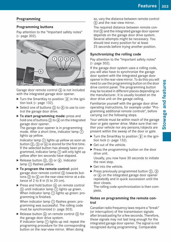
Programming
Programming buttonsPay attention to the "Important safety notes"(Y page 302).
Garage door remote controlA is not includedwith the integrated garage door opener.X Turn the SmartKey to position2 in the igni-tion lock (Y page 132).
X Select one of buttons; to? to use to con-trol the garage door drive.
X To start programming mode: press andhold one of buttons; to? on the integratedgarage door opener.The garage door opener is in programmingmode. After a short time, indicator lamp:lights up yellow.Indicator lamp: lights up yellow as soon asbutton;,= or? is stored for the first time.If the selected button has already been pro-grammed, indicator lamp: will only light upyellow after ten seconds have elapsed.
X Release button;,= or?. Indicatorlamp: flashes yellow.
X To program the remote control: pointgarage door remote controlA towards but-tons; to? on the rear-view mirror at a dis-tance of 2 to 8 in (5 to 20 cm).
X Press and hold buttonB on remote controlA until indicator lamp: lights up green.When indicator lamp: lights up green: pro-gramming is finished.When indicator lamp: flashes green: pro-gramming was successful. The rolling codemust be synchronized (Y page 303).
X Release buttonB on remote controlA forthe garage door drive system.If indicator lamp: lights up red: repeat theprograming procedure for the correspondingbutton on the rear-view mirror. When doing
so, vary the distance between remote controlA and the rear-view mirror.The required distance between remote con-trolA and the integrated garage door openerdepends on the garage door drive system.Several attempts might be necessary. Youshould test every position for at least25 seconds before trying another position.
Synchronizing the rolling codePay attention to the "Important safety notes"(Y page 302).If the garage door system uses a rolling code,you will also have to synchronize the garagedoor system with the integrated garage dooropener in the rear-viewmirror. To do this youwillneed to use the programming button on the doordrive control panel. The programming buttonmay be located in different places depending onthe manufacturer. It is usually located on thedoor drive unit on the garage ceiling.Familiarize yourself with the garage door driveoperating instructions, for example under "Pro-gramming additional remote controls", beforecarrying out the following steps.Your vehicle must be within reach of the garagedoor or gate opener drive. Make sure that nei-ther your vehicle nor any persons/objects arepresent within the sweep of the door or gate.X Turn the SmartKey to position2 in the igni-tion lock (Y page 132).
X Get out of the vehicle.X Press the programming button on the doordrive unit.Usually, you now have 30 seconds to initiatethe next step.
X Get into the vehicle.X Press previously programmed button;,=or? on the integrated garage door openerrepeatedly and in quick succession until thedoor closes.The rolling code synchronization is then com-plete.
Notes on programming the remote con-trolCanadian radio frequency laws require a "break"(or interruption) of the transmission signalsafter broadcasting for a few seconds. Therefore,these signals may not last long enough for theintegrated garage door opener. The signal is notrecognized during programming. Comparable
Features 303
Stow
ageandfeatures
Z

with Canadian law, someU.S. garage door open-ers also feature a "break".Proceed as follows:Rif you live in Canada.Rif you have difficulties programming thegarage door opener (regardless of where youlive) when using the programming steps.
X Press and hold one of buttons; to? on theintegrated garage door opener.After a short time, indicator lamp: lights upyellow.
X Release the button.Indicator lamp: flashes yellow.
X Press buttonB of garage door remote con-trolA for two seconds, then release it for twoseconds.
X Press buttonB of the remote controlAagain and hold for two seconds.
X Repeat this sequence on buttonB of remotecontrolA until indicator lamp: lights upgreen.When indicator lamp: lights up green: pro-gramming is finished.When indicator lamp: flashes green: pro-gramming was successful. The next step is tosynchronize the rolling code.
X Release buttonB of remote controlA of thegarage door drive.If indicator lamp: lights up red: repeat theprogramming process for the correspondingbutton on the rear-view mirror. When doingso, vary the distance between remote controlA and the rear-view mirror.The required distance between remote con-trolA and the integrated garage door openerdepends on the garage door drive system.Several attempts might be necessary. Youshould test every position for at least25 seconds before trying another position.
Problems when programmingIf you are experiencing problems programingthe integrated garage door opener on the rear-view mirror, take note of the following instruc-tions:RCheck the transmitter frequency used bygarage door drive remote controlA andwhether it is supported. The transmitter fre-quency can usually be found on the back ofremote controlA for the garage door drive.
The garage door opener is compatible withdevices which operate in the frequency rangeof 280 to 433 MHz.RReplace the batteries in garage door remotecontrolA. This increases the likelihood thatgarage door remote controlA will transmit astrong and precise signal to the integratedgarage door opener.RWhen programming, hold remote controlAat varying distances and angles and from but-tons; to?which you are programming. Tryvarious angles at a distance between 2and8 inches (5to 20 cm) or at the same angle butat varying distances.RIf another remote controlA is available forthe same garage door drive, repeat the sameprogramming steps with this remote controlA. Before performing these steps,make surethat new batteries have been installed ingarage door drive remote controlA.RNote that some remote controls only transmitfor a limited amount of time (the indicatorlamp on the remote control goes out). PressbuttonB on remote controlA again beforetransmission ends.RAlign the antenna cable of the garage dooropener unit. This can improve signal recep-tion/transmission.
Opening/closing the garage doorAfter it has been programmed, the integratedgarage door opener performs the function of thegarage door system remote control. Please alsoread the operating instructions for the garagedoor system.X Turn the SmartKey to position2 in the igni-tion lock (Y page 132).
X Press button;,= or? which you pro-grammed to operate the garage door.Garage door system with a fixed code: indi-cator lamp: lights up green.Garage door system with a rolling code: indi-cator lamp: flashes green.The transmitter will transmit a signal as longas the button is pressed. The transmission ishalted after a maximum of ten seconds andindicator lamp: lights up yellow.
X Press button;,= or? again if necessary.
304 FeaturesStow
ageandfeatures

Clearing the memoryMake sure that you clear the memory of theintegrated garage door opener before selling thevehicle.X Turn the SmartKey to position2 in the igni-tion lock (Y page 132).
X Press and hold buttons; and?.The indicator lamp initially lights up yellowand then green.
X Release buttons; and?.The memory of the integrated garage dooropener in the rear-view mirror is cleared.
Floormats
G WARNINGObjects in the driver's footwell can restrict thepedal travel or obstruct a depressed pedal.The operating and road safety of the vehicle isjeopardized. There is a risk of an accident.Make sure that all objects in the vehicle arestowed correctly, and that they cannot enterthe driver's footwell. Install the floormatssecurely and as specified in order to ensuresufficient clearance for the pedals. Do not useloose floormats and do not place floormats ontop of one another.
X Slide the relevant seat back.X To install: place the floormat in the footwell.X Press studs: onto retainers;.X To remove: pull the floormat off retainers;.X Remove the floormat.
Features 305
Stow
ageandfeatures
Z

Engine compartment
Hood
Important safety notes
G WARNINGIf the hood is unlatched, it may open up whenthe vehicle is in motion and block your view.There is a risk of an accident.Never unlatch the hood while driving. Beforeevery trip, ensure that the hood is locked.
G WARNINGWhen opening and closing the hood, it maysuddenly fall into the closed position. There isa risk of injury to persons within range ofmovement of the hood.Open and close the hood only when no one iswithin its range of movement.
G WARNINGOpening the hood when the engine is over-heated or when there is a fire in the enginecompartment could expose you to hot gasesor other service products. There is a risk ofinjury.Let an overheated engine cool down beforeopening the hood. If there is a fire in theengine compartment, keep the hood closedand contact the fire department.
G WARNINGThe engine compartment contains movingcomponents. Certain components, such asthe radiator fan, may continue to run or startagain suddenly when the ignition is off. Thereis a risk of injury.If you need to do any work inside the enginecompartment:Rswitch off the ignitionRnever reach into the area where there is arisk of danger from moving components,such as the fan rotation area
Rremove jewelry and watchesRkeep items of clothing and hair, for exam-ple, away from moving parts
Opening the hood
G WARNINGCertain components in the engine compart-ment, such as the engine, radiator and partsof the exhaust system, can become very hot.Working in the engine compartment poses arisk of injury.Where possible, let the engine cool down andtouch only the components described in thefollowing.
G WARNINGWhen the hood is open and the windshieldwipers are set inmotion, you can be injured bythe wiper linkage. There is a risk of injury.Always switch off the windshield wipers andthe ignition before opening the hood.
! Make sure that the windshield wipers arenot folded away from the windshield. Youcould otherwise damage the windshield wip-ers or the hood.
X Make sure that the windshield wipers areturned off.
X Pull release lever: on the hood.The hood is released.
306 Engine compartmentMaintenance
andcare

X Reach into the gap, pull hood catch handle;up and lift the hood.If you lift the hood by approximately 15 in(40 cm), the hood is opened and held openautomatically by the gas-filled strut.
Closing the hoodX Lower the hood and let it fall from a height ofapproximately 8 in (20 cm).
X Check that the hood has engaged properly.If the hood can be raised slightly, it is notproperly engaged. Open it again and close itwith a little more force.
RadiatorDo not cover up the radiator, such as with athermal mat or insect protection cover. Other-wise, the values of the European on-board diag-nostics may be affected. Some of these read-ings are required by law andmust be accurate atall times.
Engine oil
Important safety notes
G WARNINGCertain components in the engine compart-ment, such as the engine, radiator and partsof the exhaust system, can become very hot.Working in the engine compartment poses arisk of injury.Where possible, let the engine cool down andtouch only the components described in thefollowing.
G WARNINGThe engine compartment contains movingcomponents. Certain components, such asthe radiator fan, may continue to run or startagain suddenly when the ignition is off. Thereis a risk of injury.If you need to do any work inside the enginecompartment:Rswitch off the ignitionRnever reach into the area where there is arisk of danger from moving components,such as the fan rotation areaRremove jewelry and watchesRkeep items of clothing and hair, for exam-ple, away from moving parts
G WARNINGIf engine oil comes into contact with hot com-ponents in the engine compartment, it mayignite. There is a risk of fire and injury.Make sure that engine oil is not spilled next tothe filler neck. Let the engine cool down andthoroughly clean the engine oil off the com-ponents before starting the engine.
G WARNINGOpening the hood when the engine is over-heated or when there is a fire in the enginecompartment could expose you to hot gasesor other service products. There is a risk ofinjury.Let an overheated engine cool down beforeopening the hood. If there is a fire in theengine compartment, keep the hood closedand contact the fire department.
General notesDepending on your driving style, the vehicleconsumes up to 0.9 US qt (0.8 l) of oil per600 miles (1000 km). The oil consumption maybe higher than this when the vehicle is new or ifyou frequently drive at high engine speeds.Depending on the engine, the oil dipstickmay bein a different location.
Engine compartment 307
Maintenance
andcare
Z
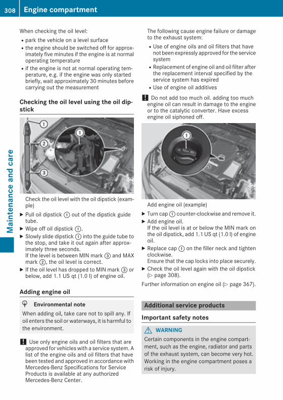
When checking the oil level:Rpark the vehicle on a level surfaceRthe engine should be switched off for approx-imately five minutes if the engine is at normaloperating temperatureRif the engine is not at normal operating tem-perature, e.g. if the engine was only startedbriefly, wait approximately 30 minutes beforecarrying out the measurement
Checking the oil level using the oil dip-stick
Check the oil level with the oil dipstick (exam-ple)
X Pull oil dipstick: out of the dipstick guidetube.
X Wipe off oil dipstick:.X Slowly slide dipstick: into the guide tube tothe stop, and take it out again after approx-imately three seconds.If the level is between MIN mark= and MAXmark;, the oil level is correct.
X If the oil level has dropped to MIN mark= orbelow, add 1.1 US qt (1.0 l) of engine oil.
Adding engine oil
H Environmental noteWhen adding oil, take care not to spill any. Ifoil enters the soil or waterways, it is harmful tothe environment.
! Use only engine oils and oil filters that areapproved for vehicleswith a service system. Alist of the engine oils and oil filters that havebeen tested and approved in accordance withMercedes-Benz Specifications for ServiceProducts is available at any authorizedMercedes-Benz Center.
The following cause engine failure or damageto the exhaust system:RUse of engine oils and oil filters that havenot been expressly approved for the servicesystemRReplacement of engine oil and oil filter afterthe replacement interval specified by theservice system has expiredRUse of engine oil additives
! Do not add too much oil. adding too muchengine oil can result in damage to the engineor to the catalytic converter. Have excessengine oil siphoned off.
Add engine oil (example)X Turn cap: counter-clockwise and remove it.X Add engine oil.If the oil level is at or below the MIN mark onthe oil dipstick, add 1.1 US qt (1.0 l) of engineoil.
X Replace cap: on the filler neck and tightenclockwise.Ensure that the cap locks into place securely.
X Check the oil level again with the oil dipstick(Y page 308).
Further information on engine oil (Y page 367).
Additional service products
Important safety notes
G WARNINGCertain components in the engine compart-ment, such as the engine, radiator and partsof the exhaust system, can become very hot.Working in the engine compartment poses arisk of injury.
308 Engine compartmentMaintenance
andcare

Where possible, let the engine cool down andtouch only the components described in thefollowing.
G WARNINGThe engine compartment contains movingcomponents. Certain components, such asthe radiator fan, may continue to run or startagain suddenly when the ignition is off. Thereis a risk of injury.If you need to do any work inside the enginecompartment:Rswitch off the ignitionRnever reach into the area where there is arisk of danger from moving components,such as the fan rotation areaRremove jewelry and watchesRkeep items of clothing and hair, for exam-ple, away from moving parts
G WARNINGThe cooling system is pressurized, particularlywhen the motor is warm. If you open the cap,you could be scalded if hot coolant sprays out.There is a risk of injury.Let the engine cool down before you open thecap. Wear gloves and eye protection. Slowlyopen the cap to relieve pressure.
G WARNINGOpening the hood when the engine is over-heated or when there is a fire in the enginecompartment could expose you to hot gasesor other service products. There is a risk ofinjury.Let an overheated engine cool down beforeopening the hood. If there is a fire in theengine compartment, keep the hood closedand contact the fire department.
Checking coolant level
Checking the coolant level (example)X Park the vehicle on a level surface.Only check the coolant level when the vehicleis on a level surface and the engine has cooleddown.
X Turn the SmartKey to position2 in the igni-tion lock (Y page 132).
orX Press the Start/Stop button twice on vehicleswith KEYLESS-GO or the KEYLESS-GO startfunction (Y page 133).
X Check the coolant temperature display in theinstrument cluster (Y page 36).The coolant temperature must be below158 ‡ (70 †).
X Turn the SmartKey to positiong in the igni-tion lock (Y page 132).
orX Press the Start/Stop button once on vehicleswith KEYLESS-GO or the KEYLESS-GO startfunction (Y page 133).
X Slowly turn cap: half a turn counter-clock-wise and allow excess pressure to escape.
X Turn cap: further counter-clockwise andremove it.If the coolant is at the level of marker bar=in the filler neck when cold, there is enoughcoolant in coolant expansion tank;.If the coolant level is approximately 0.6 in(1.5 cm) abovemarker bar= in the filler neckwhenwarm, there is enough coolant in expan-sion tank;.
X If necessary, add coolant that has been testedand approved by Mercedes-Benz.
X Replace cap: and turn it clockwise as far asit will go.
For further information on coolant, see(Y page 368).
Engine compartment 309
Maintenance
andcare
Z

Adding washer fluid to the windshieldwasher system
G WARNINGWindshield washer concentrate could ignite ifit comes into contact with hot engine compo-nents or the exhaust system. There is a risk offire and injury.Make sure that no windshield washer con-centrate is spilled next to the filler neck.
Example: adding liquid to the windshieldwasher system
X To open: pull cap: upwards by the tab andopen.
X Add the premixed washer fluid.X To close: press cap: onto the filler neckuntil it engages.
If the washer fluid level drops below the recom-mended minimum fluid level of 1.1 US qt (1.0 l),a message appears in the multifunction displayprompting you to addwasher fluid (Y page 254).Further information on washer fluid(Y page 369).
ASSYST PLUS
Service messageThe ASSYST PLUS service interval displayinforms you of the next service due date.Information on the type of service and serviceintervals (see the separate Maintenance Book-let).Further information can be obtained at a quali-fied specialist workshop, e.g. an authorizedMercedes-Benz Center, or athttp://www.mbusa.com (USA only).
i The ASSYST PLUS service interval displaydoes not show any information on the engineoil level. Observe the notes on the engine oillevel (Y page 307).
The multifunction display shows a service mes-sage for several seconds, for example:RService A in XX DaysRService A DueRService A Overdue by XX DaysDepending on the operating conditions of thevehicle, the remaining time or distance until thenext service due date is displayed.The letter A or B, possibly in connection with anumber or another letter, indicates the type ofservice. A stands for a minor service and B for amajor service.You can obtain further information from anauthorized Mercedes-Benz Center.The ASSYST PLUS service interval display doesnot take into account any periods of time duringwhich the battery is disconnected.Maintaining the time-dependent service sched-ule:X Note down the service due date displayed inthe multifunction display before disconnect-ing the battery.
orX After reconnecting the battery, subtract thebattery disconnection periods from the ser-vice date shown on the display.
Hiding a service messageX Press thea or% button on the steeringwheel.
Displaying service messagesX Switch on the ignition.X Useò on the steering wheel to call up thelist of menus.
X Press9 or: on the steering wheel toselect the Service menu and confirm witha.
X Press9 or: on the steering wheel toselect the ASSYST PLUS submenu and con-firm witha.The service due date appears in the multi-function display.
310 ASSYST PLUSMaintenance
andcare

Information about Service
Resetting the ASSYST PLUS serviceinterval display! If the ASSYST PLUS service interval displayhas been inadvertently reset, this setting canbe corrected at a qualified specialist work-shop.Have service work carried out as described intheMaintenance Booklet. This may otherwiselead to increased wear and damage to themajor assemblies or the vehicle.
A qualified specialist workshop, e.g. an author-ized Mercedes-Benz Center, will reset theASSYST PLUS service interval display after theservice work has been carried out. You can alsoobtain further information on maintenancework, for example.
Special service requirementsThe specified maintenance interval takes onlythe normal operation of the vehicle intoaccount. Under arduous operating conditions orincreased load on the vehicle, maintenancework must be carried out more frequently, forexample:RRegular city driving with frequent intermedi-ate stopsRIf the vehicle is primarily used to travel shortdistancesRUse in mountainous terrain or on poor roadsurfacesRif the engine is often left idling for long periodsUnder these or similar conditions, have, forexample, the air filter, engine oil and oil filterreplaced or changed more frequently. Underarduous operating conditions, the tires must becheckedmore often. Further information can beobtained at a qualified specialist workshop, e.g.an authorized Mercedes-Benz Center.
Driving abroadAn extensive Mercedes-Benz Service network isalso available in other countries. You can obtainfurther information from any authorizedMercedes-Benz Center.
Care
General notes! For cleaning your vehicle, do not use any ofthe following:Rdry, rough or hard clothsRabrasive cleaning agentsRsolventsRcleaning agents containing solventsDo not scrub.Do not touch the surfaces or protective filmswith hard objects, e.g. a ring or ice scraper.You could otherwise scratch or damage thesurfaces and protective film.
! Do not park your vehicle for a long period oftime directly after cleaning, particularly aftercleaning the wheel rim with wheel cleaner.Wheel cleaner can lead to the increased cor-rosion of the brake discs and pads. Therefore,drive for a few minutes after cleaning. Byheating up the brakes, the brake discs andpads dry. The vehicle can then be parked for along period of time.
H Environmental noteDispose of empty packaging and cleaningcloths in an environmentally responsibleman-ner.
Regular care of your vehicle is a condition forretaining the quality in the long term.Use care products and cleaning agents recom-mended and approved by Mercedes-Benz.
Washing the vehicle and cleaning thepaintwork
Automatic car wash
G WARNINGBraking efficiency is reduced after washingthe vehicle. There is a risk of an accident.After the vehicle has been washed, brakecarefully while paying attention to the trafficconditions until full braking power is restored.
! When DISTRONIC PLUS or the HOLD func-tion is activated, the vehicle brakes automat-ically in certain situations.
Care 311
Maintenance
andcare
Z

To avoid damage to the vehicle, deactivateDISTRONIC PLUS and the HOLD function inthe following or similar situations:Rwhen towing the vehicleRin the car wash
! Never clean your vehicle in a TouchlessAutomatic Car Wash as these use specialcleaning agents. These cleaning agents candamage the paintwork or plastic parts.
! Make sure that:Rthe side windows and sliding sunroof areclosed completelyRthe blower is switched offRthe windshield wiper switch is in position 0Rthe 360° camera or the rear view camera isdeactivated
The vehicle may otherwise be damaged.
! If the SmartKey is within the rear detectionrange of KEYLESS-GO, the following situa-tions, for example, could lead to the uninten-tional opening of the tailgate:Rusing a car washRusing a power washerMake sure that the SmartKey is at least 3 maway from the vehicle.
! If the SmartKey is within the rear detectionrange of KEYLESS-GO, the following situa-tions, for example, could lead to the uninten-tional opening of the tailgate:Rusing a car washRusing a power washerMake sure that the SmartKey is at least 10 ft(3 m) away from the vehicle.
! Make sure that the automatic transmissionis in neutral positioni when washing yourvehicle in a tow-through car wash. The vehiclemay otherwise be damaged.ROperating with the SmartKey:Do not remove the SmartKey from the igni-tion lock. Do not open the driver's doorwhen the engine is switched off or at verylow speeds. Otherwise, when in transmis-sion positionh ork, the automatictransmission will automatically switch topark positionj and block the wheels.ROperating with the Start/Stop button:Do not open the driver's door when theengine is switched off or at very low
speeds. Otherwise, when in transmissionpositionh ork, the automatic transmis-sion will automatically switch to park posi-tionj and block the wheels.
Observe the following to make sure that theautomatic transmission stays in neutral positioni:Operating with the SmartKey and Start/Stopbutton:X Make sure that the ignition is switched on.X Make sure that the vehicle is stationary.X Depress and hold the brake pedal.Operating with the Start/Stop button only:X Engage park positionj.X Release the brake pedal.X Remove Start/Stop button from ignition lock(Y page 133).
X Insert the SmartKey into the ignition lock.X Switch on the ignition.X Depress and hold the brake pedal.Operating with the SmartKey and Start/Stopbutton:X Shift to neutrali.X Release the brake pedal.X Release the electric parking brake, if neces-sary.
X Switch off the ignition and leave the SmartKeyin the ignition lock.
You can wash the vehicle in an automatic carwash from the very start.If the vehicle is very dirty, pre-wash it beforecleaning it in an automatic car wash.After using an automatic car wash, wipe off waxfrom the windshield and the wiper blades. Thiswill prevent smears and reduce wiping noisescaused by residue on the windshield.
Washing by handIn some countries, washing by hand is onlyallowed at specially equipped washing bays.Observe the legal requirements in each country.X Do not use hot water and do not wash thevehicle in direct sunlight.
X Use a soft sponge to clean.X Use a mild cleaning agent, such as a carshampoo approved by Mercedes-Benz.
312 CareMaintenance
andcare
X Thoroughly hose down the vehicle with a gen-tle jet of water.
X Do not point thewater jet directly towards theair inlet.
X Use plenty of water and rinse out the spongefrequently.
X Rinse the vehicle with clean water and drythoroughly with a chamois.
X Do not let the cleaning agent dry on the paint-work.
Carefully remove all deposits of road salt assoon as possible when driving in winter.
Power washers
G WARNINGThe water jet from a circular jet nozzle (dirtblasters) can cause invisible exterior damageto the tires or chassis components. Compo-nents damaged in this way may fail unexpect-edly. There is a risk of an accident.Do not use power washers with circular jetnozzles to clean the vehicle. Have damagedtires or chassis components replaced imme-diately.
! Always maintain a distance of at least11.8 in (30 cm) between the vehicle and thepower washer nozzle. Information about thecorrect distance is available from the equip-ment manufacturer.Move the power washer nozzle around whencleaning your vehicle.Do not aim directly at any of the following:RTiresRDoor gaps, roof gaps, joints, etc.RElectrical componentsRBatteryRConnectorsRLampsRSealsRTrimRVentilation slotsDamaged seals or electrical components canlead to leaks or failures.
! Vehicles with decorative film: parts of yourvehicle are covered with a decorative film.Maintain a distance of at least 27.5 in (70 cm)
between the parts of the vehicle covered withthe film and the nozzle of the high pressurecleaner.Information about the correct distance isavailable from the equipment manufacturer.Move the power washer nozzle around whencleaning your vehicle.
! If the SmartKey is within the rear detectionrange of KEYLESS-GO, the following situa-tions, for example, could lead to the uninten-tional opening of the tailgate:Rusing a car washRusing a power washerMake sure that the SmartKey is at least 3 maway from the vehicle.
! If the SmartKey is within the rear detectionrange of KEYLESS-GO, the following situa-tions, for example, could lead to the uninten-tional opening of the tailgate:Rusing a car washRusing a power washerMake sure that the SmartKey is at least 10 ft(3 m) away from the vehicle.
Cleaning the paintwork! Do not affix:RstickersRfilmsRmagnetic plates or similar itemsto painted surfaces. You could otherwisedamage the paintwork.
Scratches, corrosive deposits, areas affected bycorrosion and damage caused by inadequatecare cannot always be completely repaired. Insuch cases, visit a qualified specialist workshop.X Remove dirt immediately, where possible,while avoiding rubbing too hard.
X Soak insect remains with insect remover andrinse off the treated areas afterwards.
X Soak bird droppings with water and rinse offthe treated areas afterwards.
X Remove coolant, brake fluid, tree resin, oils,fuels and greases by rubbing gently with acloth soaked in petroleum ether or lighterfluid.
X Use tar remover to remove tar stains.X Use silicone remover to remove wax.
Care 313
Maintenance
andcare
Z

If water no longer forms "beads" on the paintsurface, use the paint care products recommen-ded and approved byMercedes-Benz. This is thecase approximately every three to five months,depending on the climate conditions and thecare product used.The cleaning product Paint Cleaner, which hasbeen recommended and approved byMercedes-Benz, should be used when dirt haspenetrated the paint surface.Also use Paint Cleaner on paint that has becomedull.Do not use these care products in the sun or onthe hood while the hood is hot.X Use a suitable touch-up stick, e.g. MB Touch-Up Stick, to repair slight damage to the paint-work quickly and provisionally.
Matte finish care! Never polish the vehicle or the light alloywheels. Polishing causes the finish to shine.
! The following may cause the paint tobecome shiny and thus reduce the matteeffect:Rstrong rubbing of the paintwork withunsuitable materialsRfrequent use of automatic car washesRwashing the vehicle in direct sunlight
! Never use paint cleaner, buffing or polishingproducts, or gloss preserver, e.g. wax, for thepurpose of paintwork care. These productsare only suitable for high-gloss surfaces. Theiruse on vehicles with matte paintwork leads toconsiderable surface damage or, more spe-cifically, to shiny, spotted areas.Always have paintwork repairs carried out at aqualified specialist workshop.
! Do not use wash programs with a hot waxtreatment under any circumstances.
Observe these notes if your vehicle has a clearmatte finish. This will help you to avoid damageto the paintwork due to incorrect treatment.These notes also apply to light alloy wheels witha clear matte finish.The vehicle should preferably be washed byhand using a soft sponge, car shampoo andplenty of water.
Use only insect remover and car shampoo fromthe range of approved Mercedes-Benz careproducts.
Cleaning the vehicle parts
Cleaning the wheels
G WARNINGThe water jet from a circular jet nozzle (dirtblasters) can cause invisible exterior damageto the tires or chassis components. Compo-nents damaged in this way may fail unexpect-edly. There is a risk of an accident.Do not use power washers with circular jetnozzles to clean the vehicle. Have damagedtires or chassis components replaced imme-diately.
! Do not use acidic wheel cleaning productsto remove brake dust. This could damagewheel bolts and brake components.
! Do not park your vehicle for a long period oftime directly after cleaning, particularly aftercleaning the wheel rim with wheel cleaner.Wheel cleaner can lead to the increased cor-rosion of the brake discs and pads. Therefore,drive for a few minutes after cleaning. Byheating up the brakes, the brake discs andpads dry. The vehicle can then be parked for along period of time.
Cleaning the windows
G WARNINGYou could become trapped by the windshieldwipers if they start moving while cleaning thewindshield or wiper blades. There is a risk ofinjury.Always switch off the windshield wipers andthe ignition before cleaning the windshield orwiper blades.
! Do not use dry cloths, abrasive products,solvents or cleaning agents containing sol-vents to clean the inside of the windows. Donot touch the insides of the windows withhard objects, e.g. an ice scraper or ring. Thereis otherwise a risk of damaging the windows.
314 CareMaintenance
andcare

! Clean the water drainage channels of thewindshield and the rear window at regularintervals. Deposits such as leaves, petals andpollen may under certain circumstances pre-vent water from draining away. This can leadto corrosion damage and damage to elec-tronic components.
X Clean the inside and outside of the windowswith a damp cloth and a cleaning product thatis recommended and approved by Mercedes-Benz.
Cleaning wiper blades
G WARNINGYou could become trapped by the windshieldwipers if they start moving while cleaning thewindshield or wiper blades. There is a risk ofinjury.Always switch off the windshield wipers andthe ignition before cleaning the windshield orwiper blades.
! Do not pull the wiper blade. Otherwise, thewiper blade could be damaged.
! Do not clean wiper blades too often and donot rub them too hard. Otherwise, the graph-ite coating could be damaged. This couldcause wiper noise.
! Hold the wiper arm securely when foldingback. The windshield could be damaged if thewiper arm smacks against it suddenly.
X Fold the windshield wiper arms away from thewindshield (Y page 120).
X Carefully clean the wiper blades with a dampcloth.
X Fold the windshield wiper arms back againbefore switching on the ignition.
Cleaning the exterior lighting! Only use cleaning agents or cleaning clothswhich are suitable for plastic light lenses.Unsuitable cleaning agents or cleaning clothscould scratch or damage the plastic light len-ses.
X Clean the plastic lenses of the exterior light-ing using a wet sponge and a mild cleaningagent, e.g. Mercedes-Benz car shampoo orcleaning cloths.
Cleaning the mirror turn signals! Only use cleaning agents or cleaning clothsthat are suitable for plastic lenses. Unsuitablecleaning agents or cleaning cloths couldscratch or damage the plastic lenses of themirror turn signals.
X Clean the plastic lenses of the mirror turn sig-nals in the exterior mirror housing using a wetsponge and mild cleaning agent, e.g.Mercedes-Benz car shampoo or cleaningcloths.
Cleaning the side running board! Do not clean the aluminum inserts of theside running board with alkaline or acidiccleaners, such as wheel cleaner. Do not useacidic wheel cleaners to remove brake dust.The aluminum inserts could otherwise bedamaged.
Cleaning the sensors! If you clean the sensors with a powerwasher, make sure that you keep a distanceof at least 11.8 in (30 cm) between the vehicleand the power washer nozzle. Informationabout the correct distance is available fromthe equipment manufacturer.
X Clean sensors: of the driving systems withwater, car shampoo and a soft cloth.
Care 315
Maintenance
andcare
Z

Cleaning the rear viewcamera and360°camera! Do not clean the camera lens and the areaaround the rear view camera or 360° camerawith a power washer.
X Make sure that the vehicle is stationary.X Turn the SmartKey to position1 or2 in theignition lock (Y page 132).
orX Press the Start/Stop button once or twice onvehicles with KEYLESS-GO or the KEYLESS-GO start function (Y page 133).
X Open the camera cover for cleaning via themultimedia system (see Digital Operator'sManual).
X To clean the camera: use clean water and asoft cloth to clean camera lens:.
When you switch off the ignition, the cameracover closes automatically.
Cleaning the exhaust pipes
G WARNINGThe exhaust tail pipe and tail pipe trim canbecome very hot. If you come into contactwith these parts of the vehicle, you could burnyourself. There is a risk of injury.Always be particularly careful around theexhaust tail pipe and the tail pipe trim. Allowthese components to cool down before touch-ing them.
! Do not clean the exhaust pipe with acid-based cleaning agents, such as bathroomcleaner or wheel cleaner.
Impurities combined with the effects of road gritand corrosive environmental factors may cause
flash rust to form on the surface. You canrestore the original shine of the exhaust pipe bycleaning it regularly, especially in winter andafter washing.X Clean the exhaust pipe with a care producttested and approved by Mercedes-Benz.
Cleaning the trailer tow hitch
H Environmental noteDispose of rags soaked in oil and grease in anenvironmentally responsible manner.
! Please note the care instructions in thetrailer coupling manufacturer's operatinginstructions.
The ball coupling must be cleaned if it becomesdirty or corroded.X Remove rust on the ball, e.g. with a wirebrush.
X Remove dirt with a clean, lint-free cloth or abrush.
X After cleaning, lightly oil or grease the ballcoupling.
X Check that the vehicle's trailer tow hitch isworking properly.
You can also have the maintenance work on theball coupling and the trailer tow hitch carried outby a qualified specialist workshop.
Interior care
Cleaning the display! For cleaning, do not use any of the following:Ralcohol-based thinner or gasolineRabrasive cleaning agentsRcommercially-available household cleaningagents
These may damage the display surface. Donot put pressure on the display surface whencleaning. This could lead to irreparable dam-age to the display.
316 CareMaintenance
andcare

X Before cleaning the display, make sure that itis switched off and has cooled down.
X Clean the display surface using a commer-cially available microfiber cloth and TFT/LCDdisplay cleaner.
X Dry the display surface using a dry microfibercloth.
Cleaning the plastic trim
G WARNINGCare products and cleaning agents containingsolvents cause surfaces in the cockpit tobecome porous. As a result, plastic parts maycome loose in the event of air bag deploy-ment. There is a risk of injury.Do not use any care products and cleaningagents to clean the cockpit.
! Never attach the following to plastic surfa-ces:RstickersRfilmsRperfume oil container or similarYou could otherwise damage the plastic.
! Do not allow cosmetics, insect repellent orsunscreen to come into contact with the plas-tic trim. Thismaintains the high-quality look ofthe surfaces.
X Wipe the plastic trim with a damp, lint-freecloth, e.g. a microfiber cloth.
X Heavy soiling: use care and cleaning prod-ucts recommended and approved byMercedes-Benz.The surface may change color temporarily.Wait until the surface is dry again.
Cleaning the steering wheel and selec-tor leverX Thoroughly wipe with a damp cloth or useleather care agents that have been recom-mended and approved by Mercedes-Benz.
Cleaning genuine wood and trim ele-ments! Do not use solvent-based cleaning agentssuch as tar remover, wheel cleaners, polishes
or waxes. There is otherwise a risk of damag-ing the surface.
! Do not use chrome polish on trim pieces.The trim pieces have a chrome look but aremostly made of anodized aluminum and canlose their shine if chrome polish is used. Usea damp, lint-free cloth instead when cleaningthe trim pieces.If the chrome-plated trim pieces are verydirty, you can use a chrome polish. If you areunsure as to whether the trim pieces arechrome-plated or not, consult an authorizedMercedes-Benz Center.
X Wipe the wooden trim and trim pieces with adamp, lint-free cloth, e.g. a microfiber cloth.
X Trim elements with piano black finish:wipewith a soft, damp cotton cloth. Use cleanwater.
X Heavy soiling: use care and cleaning prod-ucts recommended and approved byMercedes-Benz.
Cleaning the seat covers
General notes! Donot use amicrofiber cloth to clean coversmade out of real leather, artificial leather orDINAMICA. If used often, these can damagethe cover.
Note that regular care is essential to ensure thatthe appearance and comfort of the covers isretained over time.
Genuine leather seat covers! To retain the natural appearance of theleather, observe the following cleaninginstructions:RClean genuine leather covers carefully witha damp cloth and then wipe the coversdown with a dry cloth.RMake sure that the leather does notbecome soaked. It may otherwise becomerough and cracked.ROnly use leather care agents that havebeen tested and approved by Mercedes-Benz. You can obtain these from a qualifiedspecialist workshop.
Leather is a natural product.It exhibits natural surface characteristics, forexample:
Care 317
Maintenance
andcare
Z

Rdifferences in the textureRmarks caused by growth and injuryRslight nuances of colorThese are characteristics of leather and notmaterial defects.
Seat covers of other materials! Observe the following when cleaning:Rclean artificial leather covers with a clothmoistened with a solution containing 1%detergent (e.g. dish washing liquid).Rclean cloth covers with a microfiber clothmoistened with a solution containing 1%detergent (e.g. dish washing liquid). Rubcarefully and always wipe entire seat sec-tions to avoid leaving visible lines. Leavethe seat to dry afterwards. Cleaning resultsdepend on the type of dirt and how long ithas been there.Rclean DINAMICA covers with a damp cloth.Make sure that you wipe entire seat sec-tions to avoid leaving visible lines.
Cleaning the seat belts
G WARNINGSeat belts can become severely weakened ifbleached or dyed. This could cause the seatbelts to tear or fail, for instance, in the event ofan accident. This poses an increased risk ofinjury or fatal injury.Never bleach or dye the seat belts.
! Do not clean the seat belts using chemicalcleaning agents. Do not dry the seat belts byheating at temperatures above 176 ‡ (80†)or in direct sunlight.
X Use clean, lukewarmwater and soap solution.
Cleaning the headliner and carpetsX Headliner: if it is very dirty, use a soft brush ordry shampoo.
X Carpets: use the carpet and textile cleaningagents recommended and approved byMercedes-Benz.
318 CareMaintenance
andcare

Where will I find...?
Reflective safety jacket
Removing/replacing the reflectivesafety jacket
The reflective safety jackets are located in thesafety jacket compartments in the stowagecompartments of the front doors. There are alsosafety jacket compartments in the stowagecompartments of the rear doors, in which reflec-tive safety jackets can be stowed.X To remove: pull out safety jacket bag:withthe reflective safety jacket by loop;.
X Open safety jacket bag: and pull out thereflective safety jacket.
X To stow: fold the reflective safety jacket, rollit up and stow it in safety jacket bag:.
X Slide safety jacket bag: along the loweredge of the armrest into the safety jacketcompartment. Meanwhile, ensure thatloop; hangs out well within reach.
X Observe the legal requirements in each indi-vidual country for the use of safety jackets.i Remove a new reflective safety jacket fromits packaging material before sliding it intothe safety jacket compartment. The packag-ingmaterial may otherwise cause it to slip outor make removing it difficult.
Information on reflective safety jackets
: Maximum number of washes; Maximum wash temperature= Do not bleach? Do not ironA Do not use a laundry dryerB Do not dry-cleanC This is a class 2 jacketRThe safety jackets only meet the require-ments defined by the legal standard:- if the correct size is used- if the reflective safety jackets are correctlyfastened
RBefore use, ensure that the reflective safetyjackets are clean and intact. The special prop-erties may otherwise be compromised.RThe reflective safety jackets should be storedin their original packaging in a dry place awayfrom sources of heat and light.RThe maximum number of washes specified isnot the only factor influencing the life span ofthe reflective safety jackets. Their life spanalso depends on use, care, storage, etc.RThe reflective safety jackets should be dis-posed of and replaced with new ones:- after 15 washes, and/or- if the reflective strips have becomescratched, and/or
- if the backing material and/or reflectivestrips have become soiled and cannot becleaned off, and/or
- if the fluorescence has faded, for exampledue to the effects of sunlight
RDispose of reflective safety jackets in an envi-ronmentally responsible manner. To do so,contact your local waste disposal company.
Where will I find...? 319
Breakdow
nassistance

Towing eye
Towing eye: is located in the left-hand stow-age well under the cargo compartment floor.X To remove: open the tailgate.X Open the cargo compartment floor(Y page 288).
X Remove towing eye:.
Vehicles with a TIREFIT kit
Removing the TIREFIT kit
The TIREFIT kit s located in the left-hand stow-age compartment.X To remove: open the tailgate.X Open the cargo compartment floor(Y page 288).
X Push retaining clamps: on the cover downso as to release them.
X Fold up cover in the direction of arrow;.X Remove tire inflation compressor= and tiresealant bottle?.
X Use the TIREFIT kit (Y page 322).
Vehicles with a tire-change tool kit
General notesApart from certain country-specific variations,the vehicles are not equipped with a tire-changetool kit.Some tools for changing a wheel are specific tothe vehicle. For more information on which tirechanging tools are required and approved toperform awheel change on your vehicle, consulta qualified specialist workshop.Necessary tire-changing tools can include, forexample:RJackRWheel chockRLug wrenchRAlignment bolt
Removing the tire-change tool kit
Example: Ratchet for jack; Lug wrench= Jack? Alignment boltA Socket wrench for ratchetB Folding wheel chockThe tire-change tool kit is located in the left-hand stowage well, under the cargo compart-ment floor.X To remove: open the tailgate.X Open the cargo compartment floor(Y page 288).
320 Where will I find...?Breakdow
nassistance

Flat tire
Preparing the vehicleYour vehicle may be equipped with:RMOExtended tires (tires with run-flat proper-ties) (Y page 321)Vehicle preparation is not necessary on vehi-cles with MOExtended tiresRa TIREFIT kit (Y page 320)Vehicles equipped with MOExtended tires arenot equipped with a TIREFIT kit at the factory. Itis therefore recommended that you additionallyequip your vehiclewith a TIREFIT kit if youmounttires that do not feature run-flat properties, e.g.winter tires. A TIREFIT kit may be obtained froma qualified specialist workshop.Information on changing and mounting wheels(Y page 357).X Stop the vehicle on solid, non-slippery andlevel ground, as far away as possible fromtraffic.
X Switch on the hazard warning lamps.X Secure the vehicle against rolling away(Y page 154).
X If possible, bring the front wheels into thestraight-ahead position.
X Switch off the engine.X Remove the SmartKey from the ignition lock.or, in vehicles with KEYLESS-GO start-functionor KEYLESS‑GOX Open the driver's door.The vehicle electronics are now in positionu. This means: "Key removed".
X Remove the Start/Stop button from the igni-tion lock (Y page 133).
X Make sure that the engine cannot be startedvia your smartphone (Y page 134).
X Make sure that the passengers are not endan-gered as they do so. Make sure that no one isnear the danger area while a wheel is beingchanged. Anyone who is not directly assistingin the wheel change should, for example,stand behind the barrier.
X Get out of the vehicle. Pay attention to trafficconditions when doing so.
X Close the driver's door.
Vehicles withMOExtended tires (tireswith run-flat characteristics)
General notesWith MOExtended tires (tires with run flat char-acteristics), you can continue to drive your vehi-cle even if there is a total loss of pressure in oneor more tires. The affected tire must not showany clearly visible damage.You can recognize a MOExtended tire by theMOExtended marking which appears on thesidewall of the tire. You will find this markingnext to the tire size designation, the load-bear-ing capacity and the speed index (Y page 351).MOExtended tires may only be used in conjunc-tion with an active tire pressure loss warningsystem or with an active tire pressure monitor.If a pressure losswarningmessage appearsin the multifunction display:Robserve the instructions in the display mes-sages (Y page 250).Rcheck the tire for damageRif driving on, observe the following notesThe driving distance possible in run-flat mode isapproximately 50 miles (80 km) when the vehi-cle is partially laden. When the vehicle is fullyladen it is approximately 19 miles (30 km).In addition to the vehicle load, the driving dis-tance possible depends upon:RVehicle speedRRoad conditionROutside temperatureThe driving distance possible in run-flat modemay be reduced by extreme driving conditionsor maneuvers, or it can be increased through amoderate style of driving.The driving distance possible in run-flat mode iscounted from the moment the tire pressure losswarning appears in the multifunction display.You must not exceed a maximum permissiblespeed of 50 mph (80 km/h).When replacing one or all tires, please observethe following specifications for your vehicle'stires:RsizeRthe type andRthe "MOExtended" markingIf a tire has gone flat and cannot be replacedwith a MOExtended tire, a standard tire may beused as a temporary measure. Make sure that
Flat tire 321
Breakdow
nassistance

you use the proper size and type (summer orwinter tires).Vehicles equipped with MOExtended tires arenot equipped with a TIREFIT kit at the factory. Itis therefore recommended that you additionallyequip your vehiclewith a TIREFIT kit if youmounttires that do not feature run-flat properties, e.g.winter tires. A TIREFIT kit may be obtained froma qualified specialist workshop.
Important safety notes
G WARNINGWhen driving in emergency mode, the drivingcharacteristics deteriorate, e.g. when corner-ing, accelerating quickly and when braking.There is a risk of an accident.Do not exceed the stated maximum speed.Avoid abrupt steering and driving maneuvers,and driving over obstacles (curbs, potholes,off-road). This applies in particular to a ladenvehicle.Stop driving in emergency mode if:Ryou hear banging noises.Rthe vehicle starts to shake.Ryou see smoke and smell rubber.RESP® is intervening constantly.Rthere are tears in the sidewalls of the tire.After driving in emergency mode, have thewheel rims checked at a qualified specialistworkshop with regard to their further use. Thedefective tire must be replaced in every case.
TIREFIT kit
Important safety notesTIREFIT is a tire sealant.You can use TIREFIT to seal punctures of up to0.16 in (4 mm), particularly those in the tiretread. You can use TIREFIT at outside tempera-tures down to Ò4 ‡ (Ò20 †).
G WARNINGIn the following situations, the tire sealant isunable to provide sufficient breakdown assis-tance, as it is unable to seal the tire properly:Rthere are cuts or punctures in the tire largerthan those mentioned above.Rthe wheel rim is damaged.Ryou have driven at very low tire pressures oron a flat tire.
There is a risk of an accident.Do not drive the vehicle. Contact a qualifiedspecialist workshop.
G WARNINGThe tire sealant is harmful and causes irrita-tion. It must not come into contact with yourskin, eyes or clothing or be swallowed. Do notinhale TIREFIT fumes. Keep tire sealant awayfrom children. There is a risk of injury.If you come into contact with the tire sealant,observe the following:RRinse off the tire sealant from your skinimmediately with water.RIf the tire sealant comes into contact withyour eyes, immediately rinse them thor-oughly with clean water.RIf tire sealant is swallowed, immediatelyrinse your mouth out thoroughly and drinkplenty of water. Do not induce vomiting,and seek medical attention immediately.RImmediately change out of clothing whichhas come into contact with tire sealant.RIf an allergic reaction occurs, seek medicalattention immediately.
! After use, excess tire sealant may run out ofthe filler hose. This could cause stains.Therefore, place the tire sealant bottle withfiller hose in the plastic bag which is con-tained in the TIREFIT kit.
H Environmental noteHave the used tire sealant bottle disposed ofprofessionally, e.g. at a qualified specialistworkshop.
322 Flat tireBreakdow
nassistance
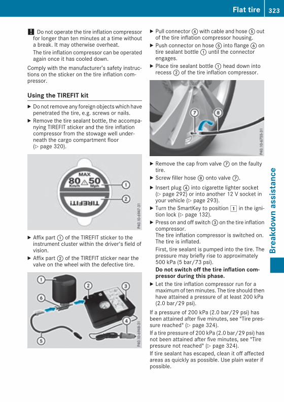
! Do not operate the tire inflation compressorfor longer than ten minutes at a time withouta break. It may otherwise overheat.The tire inflation compressor can be operatedagain once it has cooled down.
Comply with the manufacturer’s safety instruc-tions on the sticker on the tire inflation com-pressor.
Using the TIREFIT kitX Donot remove any foreign objectswhich havepenetrated the tire, e.g. screws or nails.
X Remove the tire sealant bottle, the accompa-nying TIREFIT sticker and the tire inflationcompressor from the stowage well under-neath the cargo compartment floor(Y page 320).
X Affix part: of the TIREFIT sticker to theinstrument cluster within the driver's field ofvision.
X Affix part; of the TIREFIT sticker near thevalve on the wheel with the defective tire.
X Pull connector? with cable and hoseA outof the tire inflation compressor housing.
X Push connector on hoseA into flangeB ontire sealant bottle: until the connectorengages.
X Place tire sealant bottle: head down intorecess; of the tire inflation compressor.
X Remove the cap from valveC on the faultytire.
X Screw filler hoseD onto valveC.X Insert plug? into cigarette lighter socket(Y page 292) or into another 12 V socket inyour vehicle (Y page 293).
X Turn the SmartKey to position1 in the igni-tion lock (Y page 132).
X Press on and off switch= on the tire inflationcompressor.The tire inflation compressor is switched on.The tire is inflated.First, tire sealant is pumped into the tire. Thepressure may briefly rise to approximately500 kPa (5 bar/73 psi).Do not switch off the tire inflation com-pressor during this phase.
X Let the tire inflation compressor run for amaximumof tenminutes. The tire should thenhave attained a pressure of at least 200 kPa(2.0 bar/29 psi).
If a pressure of 200 kPa (2.0 bar/29 psi) hasbeen attained after five minutes, see "Tire pres-sure reached" (Y page 324).If a tire pressure of 200 kPa (2.0 bar/29 psi) hasnot been attained after five minutes, see "Tirepressure not reached" (Y page 324).If tire sealant has escaped, clean it off affectedareas as quickly as possible. Use plain water ifpossible.
Flat tire 323
Breakdow
nassistance
Z

If your clothes are soiled with tire sealant, havethem cleaned with perchloroethylene at a drycleaner as soon as possible.
Tire pressure not reachedIf a tire pressure of 200 kPa (2.0 bar/29 psi) hasnot been attained after ten minutes:X Switch off the tire inflation compressor.X Unscrew the filler hose from the valve of thefaulty tire.Tire sealantmay escapewhen the filler hose isunscrewed.
X Very slowly drive forwards or reverse approx-imately 30 ft (10 m).
X Pump up the tire again.After amaximumof tenminutes, the tire pres-sure must be at least 200 kPa (2.0 bar/29 psi).
G WARNINGIf the required tire pressure is not reachedafter the specified time, the tire is too badlydamaged. The tire sealant cannot repair thetire in this instance. Damaged tires and a tirepressure that is too low can significantlyimpair the vehicle's braking and driving char-acteristics. There is a risk of accident.Do not continue driving. Contact a qualifiedspecialist workshop.
Tire pressure reached
G WARNINGA tire temporarily sealed with tire sealantimpairs the driving characteristics and is notsuitable for higher speeds. There is a risk ofaccident.You should therefore adapt your driving styleaccordingly and drive carefully. Do not exceedthe specified maximum speed with a tire thathas been repaired using tire sealant.
The maximum permissible speed for a tiresealed with tire sealant is 50 mph (80 km/h).The upper part of the TIREFIT sticker must beaffixed to the instrument cluster in the driver'sfield of vision.
If a tire pressure of 200 kPa (2.0 bar/29 psi) hasbeen attained after ten minutes:X Switch off the tire inflation compressor.X Unscrew the filler hose from the valve of thefaulty tire.Tire sealantmay escapewhen the filler hose isunscrewed.
X Stow the tire sealant bottle and the tire infla-tion compressor.
X Pull away immediately.X Stop after driving for approximately tenminutes and check the tire pressure with thetire inflation compressor.The tire pressure must now be at least130 kPa (1.3 bar/19 psi).
G WARNINGIf the required tire pressure is not reachedafter driving for a short period, the tire is toobadly damaged. The tire sealant cannot repairthe tire in this instance. Damaged tires and atire pressure that is too low can significantlyimpair the vehicle's braking and driving char-acteristics. There is a risk of accident.Do not continue driving. Contact a qualifiedspecialist workshop.
In cases such as the one mentioned above, con-tact an authorized Mercedes-Benz Center. Orcall 1-800-FOR-MERCedes (in the USA) or1-800-387-0100 (in Canada).X Correct the tire pressure if it is still at least130 kPa (1.3 bar/19 psi). See the Tire andLoading Information placard on the B-pillar onthe driver's side or the tire pressure table inthe fuel filler flap for values.
X To increase the tire pressure: switch on thetire inflation compressor.
324 Flat tireBreakdow
nassistance

X To reduce the tire pressure: depress pres-sure release button: next to pressuregauge;.
X When the tire pressure is correct, unscrew thefiller hose from the valve of the sealed tire.Tire sealantmay escapewhen the filler hose isunscrewed.
X Screw the valve cap onto the tire valve of thesealed tire.
X Pull the tire sealant bottle out of the tire infla-tion compressor.The filler hose remains attached to the tiresealant bottle.
X Drive to the nearest qualified specialist work-shop and have the tire changed there.
X Have the tire sealant bottle replaced as soonas possible at a qualified specialist workshop.
X Have the tire sealant bottle replaced everyfour years at a qualified specialist workshop.
Battery (vehicle)
12 V battery – important safety notesSpecial tools and expert knowledge are requiredwhen working on the battery, e.g. removal andinstallation. You should therefore have all workinvolving the battery carried out at a qualifiedspecialist workshop.
G WARNINGWork carried out incorrectly on the batterycan lead, for example, to a short circuit andthus damage the vehicle electronics. This canlead to function restrictions applying tosafety-relevant systems, e.g the lighting sys-tem, the ABS (anti-lock braking system) or theESP® (Electronic Stability Program). The oper-ating safety of your vehicle may be restricted.You could lose control of the vehicle, forexample:Rwhen brakingRin the event of abrupt steering maneuversand/or when the vehicle's speed is notadapted to the road conditions
There is a risk of an accident.In the event of a short circuit or a similar inci-dent, contact a qualified specialist workshop
immediately. Do not drive any further. Youshould have all work involving the battery car-ried out at a qualified specialist workshop.
For further information about ABS and ESP®,see (Y page 65) and (Y page 70).All vehicles except vehicles with a lithium-ion battery:
G WARNINGElectrostatic build-up can lead to the creationof sparks, which could ignite the highly explo-sive gases of a battery. There is a risk of anexplosion.Before handling the battery, touch the vehiclebody to remove any existing electrostaticbuild-up.
The highly flammable gas mixture forms whencharging the battery as well as when jump-start-ing.Always make sure that neither you nor the bat-tery is electrostatically charged. A build-up ofelectrostatic charge can be caused, for exam-ple:Rby wearing clothing made from syntheticfibersRdue to friction between clothing and seatsRif you push or pull the battery across the car-pet or other synthetic materialsRif you rub the battery with a cloth
G WARNINGDuring the charging process, a battery produ-ces hydrogen gas. If a short circuit occurs orsparks are created, the hydrogen gas canignite. There is a risk of an explosion.RMake sure that the positive terminal of aconnected battery does not come into con-tact with vehicle parts.RNever placemetal objects or tools on a bat-tery.RIt is important that you observe the descri-bed order of the battery terminals whenconnecting and disconnecting a battery.RWhen jump-starting, make sure that thebattery poles with identical polarity areconnected.
Battery (vehicle) 325
Breakdow
nassistance
Z
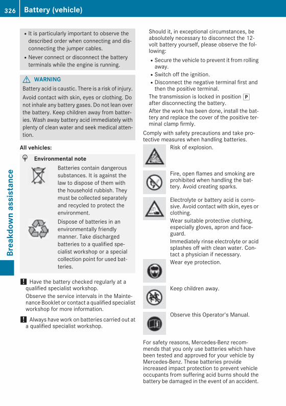
RIt is particularly important to observe thedescribed order when connecting and dis-connecting the jumper cables.RNever connect or disconnect the batteryterminals while the engine is running.
G WARNINGBattery acid is caustic. There is a risk of injury.Avoid contact with skin, eyes or clothing. Donot inhale any battery gases. Do not lean overthe battery. Keep children away from batter-ies. Wash away battery acid immediately withplenty of clean water and seek medical atten-tion.
All vehicles:
H Environmental noteBatteries contain dangeroussubstances. It is against thelaw to dispose of them withthe household rubbish. Theymust be collected separatelyand recycled to protect theenvironment.Dispose of batteries in anenvironmentally friendlymanner. Take dischargedbatteries to a qualified spe-cialist workshop or a specialcollection point for used bat-teries.
! Have the battery checked regularly at aqualified specialist workshop.Observe the service intervals in the Mainte-nanceBooklet or contact a qualified specialistworkshop for more information.
! Always havework on batteries carried out ata qualified specialist workshop.
Should it, in exceptional circumstances, beabsolutely necessary to disconnect the 12-volt battery yourself, please observe the fol-lowing:RSecure the vehicle to prevent it from rollingaway.RSwitch off the ignition.RDisconnect the negative terminal first andthen the positive terminal.
The transmission is locked in positionjafter disconnecting the battery.After the work has been done, install the bat-tery and replace the cover of the positive ter-minal clamp firmly.
Comply with safety precautions and take pro-tective measures when handling batteries.
Risk of explosion.
Fire, open flames and smoking areprohibited when handling the bat-tery. Avoid creating sparks.
Electrolyte or battery acid is corro-sive. Avoid contact with skin, eyes orclothing.Wear suitable protective clothing,especially gloves, apron and face-guard.Immediately rinse electrolyte or acidsplashes off with clean water. Con-tact a physician if necessary.Wear eye protection.
Keep children away.
Observe this Operator's Manual.
For safety reasons, Mercedes-Benz recom-mends that you only use batteries which havebeen tested and approved for your vehicle byMercedes-Benz. These batteries provideincreased impact protection to prevent vehicleoccupants from suffering acid burns should thebattery be damaged in the event of an accident.
326 Battery (vehicle)Breakdow
nassistance

In order for the battery to achieve the maximumpossible service life, it must always be suffi-ciently charged.Like other batteries, the vehicle battery maydischarge over time if you do not use the vehicle.In this case, have the battery disconnected at aqualified specialist workshop. You can alsocharge the batterywith a charger recommendedby Mercedes-Benz. Contact a qualified special-ist workshop for further information.Have the battery condition of charge checkedmore frequently if you use the vehicle mainly forshort trips or if you leave it standing idle for alengthy period. Consult a qualified specialistworkshop if you wish to leave your vehicleparked for a long period of time.Remove the SmartKey if you park the vehicleand do not require any electrical consumers.The vehicle will then use very little energy, thusconserving battery power.
Charging the 12 V batteryVehicles with a lithium-ion battery:
! Only use battery chargers with a maximumcharging voltage of 14.4 V.
All vehicles except vehicles with a lithium-ion battery:
! Only use battery chargers with a maximumcharging voltage of 14.8 V.
G WARNINGDuring charging and jump-starting, explosivegases can escape from the battery. There is arisk of an explosion.Particularly avoid fire, open flames, creatingsparks and smoking. Ensure there is sufficientventilation while charging and jump-starting.Do not lean over a battery.
G WARNINGBattery acid is caustic. There is a risk of injury.Avoid contact with skin, eyes or clothing. Donot inhale any battery gases. Do not lean overthe battery. Keep children away from batter-ies. Wash away battery acid immediately withplenty of clean water and seek medical atten-tion.
G WARNINGA discharged battery can freeze at tempera-tures below freezing point. When jump-start-ing the vehicle or charging the battery, gasescan escape from the battery. There is a risk ofan explosion.Allow the frozen battery to thaw out beforecharging it or jump-starting.
All vehicles:
! Only charge the battery using the jump-starting connection point.
The jump-starting connection point is in theengine compartment (Y page 328).X Open the hood.X Connect the battery charger to the positiveterminal and ground point in the same orderas when connecting the donor battery in thejump-starting procedure (Y page 328).
Keep away from fire and open flames. Do notlean over a battery. Never charge the battery if itis still installed in the vehicle, unless you use abattery charger which has been tested andapproved by Mercedes-Benz. A battery chargerunit specially adapted for Mercedes-Benz vehi-cles and tested and approved by Mercedes-Benz is available as an accessory. It permits thecharging of the battery in its installed position.Contact an authorized Mercedes-Benz Centerfor further information and availability. Read thebattery charger's operating instructions beforecharging the battery.All vehicles except vehicles with a lithium-ion battery: if the warning and indicator lampson the instrument cluster do not light up at lowtemperatures, it is very likely that the dis-charged battery has frozen. In this case youmayneither jump-start the vehicle nor charge thebattery. The service life of a thawed-out batterymay be shorter. The starting characteristics canbe impaired, particularly at low temperatures.Have the thawed-out battery checked at a quali-fied specialist workshop.Vehicles with a lithium-ion battery: at lowtemperatures, do not charge a batterywhich hasbeen removed using a battery charger. Allow thebattery to warm up gently first, if necessary.Otherwise, the service life can be shortened andthe starting characteristics impaired, especiallyat low temperatures.
Battery (vehicle) 327
Breakdow
nassistance
Z

Jump-starting
For the jump-starting procedure, use only the jump-starting connection point in the engine com-partment, consisting of a positive terminal and a ground point.All vehicles except vehicles with a lithium-ion battery:
G WARNINGBattery acid is caustic. There is a risk of injury.Avoid contact with skin, eyes or clothing. Do not inhale any battery gases. Do not lean over thebattery. Keep children away from batteries. Wash away battery acid immediately with plenty ofclean water and seek medical attention.
G WARNINGDuring charging and jump-starting, explosive gases can escape from the battery. There is a riskof an explosion.Particularly avoid fire, open flames, creating sparks and smoking. Ensure there is sufficient ven-tilation while charging and jump-starting. Do not lean over a battery.
G WARNINGDuring the charging process, a battery produces hydrogen gas. If a short circuit occurs or sparksare created, the hydrogen gas can ignite. There is a risk of an explosion.RMake sure that the positive terminal of a connected battery does not come into contact withvehicle parts.RNever place metal objects or tools on a battery.RIt is important that you observe the described order of the battery terminals when connectingand disconnecting a battery.RWhen jump-starting, make sure that the battery poles with identical polarity are connected.RIt is particularly important to observe the described order when connecting and disconnectingthe jumper cables.RNever connect or disconnect the battery terminals while the engine is running.
G WARNINGA discharged battery can freeze at temperatures below freezing point. When jump-starting thevehicle or charging the battery, gases can escape from the battery. There is a risk of an explosion.Allow the frozen battery to thaw out before charging it or jump-starting.
If the warning and indicator lamps do not light up on the instrument cluster when temperatures arelow, it is probably because the discharged battery has frozen. In this case, you may neither chargethe battery nor jump-start the vehicle. The service life of a thawed-out battery may be shorter. Thestarting characteristics can be impaired, particularly at low temperatures. Have the thawed-outbattery checked at a qualified specialist workshop.All vehicles:
! Vehicleswith agasoline engine: avoid repeated and lengthy starting attempts. Otherwise, thecatalytic converter could be damaged by non-combusted fuel.
328 Jump-startingBreakdow
nassistance

Do not start the vehicle using a rapid charging device. If your vehicle's battery is discharged, theengine can be jump-started from another vehicle or from a second battery using jumper cables.Observe the following points:RThe battery is not accessible in all vehicles. If the other vehicle's battery is not accessible, jump-start the vehicle using a second battery or a jump-starting device.RVehicles with a gasoline engine: only jump-start the vehicle when the engine and exhaustsystem are cold.RAll vehicles except vehicles with a lithium-ion battery: do not start the engine if the batteryis frozen. Let the battery thaw first.RJump-starting may be performed only using batteries with a nominal voltage of 12 V.ROnly use jumper cables which have a sufficient cross-section and insulated terminal clamps.RIf the battery is fully discharged, leave the battery that is being used to jump-start connected fora few minutes before attempting to start. This charges the battery slightly.RMake sure that the two vehicles do not touch.Make sure that:RThe jumper cables are not damaged.RBare parts of the terminal clamp do not come into contact with othermetal parts while the jumpercables are connected to the battery.RThe jumper cables cannot come into contact with parts that canmovewhen the engine is running,such as the V-belt pulley or the fan.
X Secure the vehicle by applying the electric parking brake.X Shift the transmission to positionj.X Make sure that the ignition is switched off. All indicator lamps in the instrument cluster must beoff. When using the SmartKey, turn the SmartKey to positionu in the ignition lock and remove it(Y page 132).
X Switch off all electrical consumers, e.g. rear window defroster, lighting, etc.X Open the hood.
Position numberB identifies the charged battery of the other vehicle or an equivalent jump-startingdevice.
Jump-starting 329
Breakdow
nassistance
Z

X Slide coverA of positive terminal: in the direction of the arrow.X Connect positive terminal: on your vehicle to positive terminal; of donor batteryB using thejumper cable, Always begin with positive terminal: on your own vehicle first.
X Start the engine of the donor vehicle and run it at idling speed.X Connect negative terminal= of donor batteryC to ground point? of your vehicle using thejumper cable, connecting the jumper cable to battery of other vehicleB first.
X Start the engine.X Before disconnecting the jumper cables, let the engine run for several minutes.X First, remove the jumper cables from ground point? and negative terminal=, then from pos-itive clamp: and positive terminal;. Begin each time at the contacts on your own vehicle first.
X Close coverA of positive terminal: after removing jumper cables.X Have the battery checked at a qualified specialist workshop.Jump-starting is not considered to be a normal operating condition.
i Jumper cables and further information regarding jump-starting can be obtained at any qualifiedspecialist workshop.
Towing and tow-starting
Important safety notes
G WARNINGFunctions relevant to safety are restricted orno longer available if:Rthe engine is not running.Rthe brake system or the power steering ismalfunctioning.Rthere is a malfunction in the voltage supplyor the vehicle's electrical system.
If your vehicle is being towed, much moreforce may be necessary to steer or brake.There is a risk of an accident.In such cases, use a tow bar. Before towing,make sure that the steering moves freely.
G WARNINGYou can no longer steer the vehicle if thesteering wheel lock has been engaged. Thereis a risk of an accident.Always switch off the ignitionwhen towing thevehicle with a tow cable or a tow bar.
G WARNINGWhen towing or tow-starting another vehicleand its weight is greater than the permissiblegross weight of your vehicle, the:Rthe towing eye could detach itselfRthe vehicle/trailer combination could roll-over.
There is a risk of an accident.When towing or tow-starting another vehicle,its weight should not be greater than the per-missible gross weight of your vehicle.
Details on the permissible gross vehicle weightof your vehicle can be found on the vehicle iden-tification plate (Y page 363).
! When Active Brake Assist, Distance PilotDISTRONIC or theHOLD function is activated,the vehicle brakes automatically in certainsituations.To avoid damage to the vehicle, deactivatethese systems in the following or similar sit-uations:Rwhen towing the vehicleRin the car wash
! Make sure that the electric parking brake isreleased. If the electric parking brake is faulty,visit a qualified specialist workshop.
! Only secure the tow rope or tow bar at thetowing eyes, or the trailer tow hitch, if availa-ble. You could otherwise damage the vehicle.
330 Towing and tow-startingBreakdow
nassistance

! Do not use the trailer tow hitch for recoveryor towing. Do not use the towing eye forrecovery. this could damage the vehicle. If indoubt, have the vehicle recovered using acrane.
! When towing, pull away slowly andsmoothly. If the tractive power is too high, thevehicles could be damaged.
! Shift the automatic transmission to positioni and do not open the driver's or front pas-senger's door during towing. The automatictransmission may otherwise shift to positionj, which could damage the transmission.
! Do not tow with sling-type equipment. Thiscould damage the vehicle.
! The vehicle can be towed a maximum of30miles (50km). The towing speed of 30mph(50 km/h) must not be exceeded.If the vehicle has to be towed more than30 miles (50km), the entire vehicle must beraised and transported.
It is better to have the vehicle transported thanto have it towed away.If the vehicle has suffered transmission damage,have it transported on a transporter or trailer.The automatic transmission must be in positioni when the vehicle is being towed. If the auto-matic transmission cannot be shifted to positioni, have the vehicle transported on a trans-porter or trailer.The battery must be connected and charged.Otherwise, you:Rcannot turn the SmartKey to position2 inthe ignition lockRcannot release the electric parking brakeRcannot shift the automatic transmission topositioni
Disarm the automatic locking feature before thevehicle is towed (Y page 84). You could other-wise be locked out when pushing or towing thevehicle.
Installing/removing the towing eye
Installing the towing eye
G WARNINGThe exhaust tail pipemay be very hot. There isa risk of burns when removing the rear cover.Do not touch the exhaust pipe. Take particularcare when removing the rear cover.
Mercedes-AMG vehicles
All other vehiclesThe brackets for the screw-in towing eye arelocated in the bumpers. They are at the rear andat the front, under covers:.
Towing and tow-starting 331
Breakdow
nassistance
Z
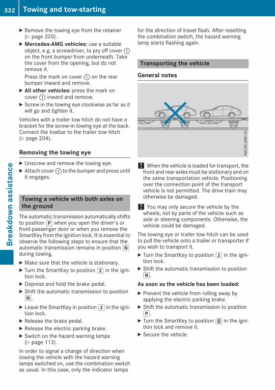
X Remove the towing eye from the retainer(Y page 320).
X Mercedes-AMG vehicles: use a suitableobject, e.g. a screwdriver, to pry off cover:on the front bumper from underneath. Takethe cover from the opening, but do notremove it.Press the mark on cover: on the rearbumper inward and remove.
X All other vehicles: press the mark oncover: inward and remove.
X Screw in the towing eye clockwise as far as itwill go and tighten it.
Vehicles with a trailer tow hitch do not have abracket for the screw-in towing eye at the back.Connect the towbar to the trailer tow hitch(Y page 204).
Removing the towing eyeX Unscrew and remove the towing eye.X Attach cover: to the bumper and press untilit engages.
Towing a vehicle with both axles onthe groundThe automatic transmission automatically shiftsto positionj when you open the driver's orfront-passenger door or when you remove theSmartKey from the ignition lock. It is essential toobserve the following steps to ensure that theautomatic transmission remains in positioniduring towing.X Make sure that the vehicle is stationary.X Turn the SmartKey to position2 in the igni-tion lock.
X Depress and hold the brake pedal.X Shift the automatic transmission to positioni.
X Leave the SmartKey in position2 in the igni-tion lock.
X Release the brake pedal.X Release the electric parking brake.X Switch on the hazard warning lamps(Y page 113).
In order to signal a change of direction whentowing the vehicle with the hazard warninglamps switched on, use the combination switchas usual. In this case, only the indicator lamps
for the direction of travel flash. After resettingthe combination switch, the hazard warninglamp starts flashing again.
Transporting the vehicle
General notes
! When the vehicle is loaded for transport, thefront and rear axlesmust be stationary and onthe same transportation vehicle. Positioningover the connection point of the transportvehicle is not permitted. The drive train mayotherwise be damaged.
! You may only secure the vehicle by thewheels, not by parts of the vehicle such asaxle or steering components. Otherwise, thevehicle could be damaged.
The towing eye or trailer tow hitch can be usedto pull the vehicle onto a trailer or transporter ifyou wish to transport it.X Turn the SmartKey to position2 in the igni-tion lock.
X Shift the automatic transmission to positioni.
As soon as the vehicle has been loaded:X Prevent the vehicle from rolling away byapplying the electric parking brake.
X Shift the automatic transmission to positionj.
X Turn the SmartKey to positionu in the igni-tion lock and remove it.
X Secure the vehicle.
332 Towing and tow-startingBreakdow
nassistance

Notes on 4MATIC vehicles! Vehicles with 4MATIC must not be towedwith either the front or the rear axle raised, asdoing so will damage the transmission.
Vehicleswith 4MATICmay either be towed awaywith both axles on the ground or be loaded upand transported.If the vehicle's transmission, front, or rear axle isdamaged, have the vehicle transported on atruck or trailer.In the event of damage to the electrical sys-tem: if the battery is defective, the automatictransmissionwill be locked in positionP. To shiftthe automatic transmission to position N, youmust provide power to the vehicle's electricalsystem in the same way as when jump-starting(Y page 328).Have the vehicle transported on a transporter ortrailer.
Tow-starting (emergency enginestarting)! Vehicles with automatic transmission mustnot be tow-started. You could otherwise dam-age the automatic transmission.i You can find information on "Jump-starting"under (Y page 328).
Fuses
Important safety notes
G WARNINGIf you manipulate or bridge a faulty fuse or ifyou replace it with a fuse with a higher amper-age, the electric cables could be overloaded.This could result in a fire. There is a risk of anaccident and injury.Always replace faulty fuses with the specifiednew fuses having the correct amperage.
Blown fuses must be replaced with fuses of thesame rating, which you can recognize by thecolor and value. The fuse ratings are listed in thefuse allocation chart.The fuse allocation chart is on the fuse box in thecargo compartment (Y page 334).
If a newly inserted fuse also blows, have thecause traced and rectified at a qualified special-ist workshop, e.g. an authorizedMercedes-BenzCenter.
! Only use fuses that have been approved forMercedes-Benz vehicles and which have thecorrect fuse rating for the system concerned.Otherwise, components or systems could bedamaged.
! Make sure that no moisture can enter thefuse box when the cover is open.
! When closing the cover, make sure that it islying correctly on the fuse box.Moisture seep-ing in or dirt could otherwise impair the oper-ation of the fuses.
The fuses in your vehicle serve to close downfaulty circuits. If a fuse blows, all the compo-nents on the circuit and their functions stopoperating.
Before changing a fuseObserve the important safety notes(Y page 333)X Switch off the engine.X Switch off all electrical consumers.X Make sure that the ignition is switched off(Y page 133).
orX When using the SmartKey, turn the SmartKeyto positionu in the ignition lock and removeit (Y page 132).
X Secure the vehicle against rolling away(Y page 154).
All indicator lamps in the instrument clustermust be off.The fuses are located in various fuse boxes:RFuse box on the driver's side of the dashboardRFuse box in the front-passenger footwellRFuse box in the engine compartment on thedriver's sideRFuse box under the cargo compartment flooron the right-hand side of the vehicle, whenviewed in the direction of travel
Fuses 333
Breakdow
nassistance
Z

Dashboard fuse boxThe fuse box is under a cover on the side of thedashboard. You can obtain further informationfrom an authorized Mercedes-Benz Center.
Fuse box in the front-passenger foot-well
X Open the front-passenger door.X To open: fold cover: out towards the rearand remove it.
X To close: clip in cover: at the rear.X Fold cover: forwards until it engages.
Fuse box in the engine compartment
G WARNINGWhen the hood is open and the windshieldwipers are set inmotion, you can be injured bythe wiper linkage. There is a risk of injury.Always switch off the windshield wipers andthe ignition before opening the hood.
X Open the hood (Y page 306).X To open: turn fasteners; on cover: coun-ter-clockwise as far as they will go.
X Remove fuse box cover: up.
X Use a dry cloth to remove any moisture fromthe fuse box.
X Loosen screws=, fold up fuse box lid? andremove it.
X To close: check whether the seal is posi-tioned correctly in lid?.
X Insert lid? into the bracket at the rear of thefuse box.
X Fold down lid? of the fuse box and tightenscrews=.
X Insert cover: and turn fasteners; clock-wise as far as they will go.
X Close the hood.
Fuse box in the cargo compartment
334 FusesBreakdow
nassistance

OpeningX Open the tailgate.X Lift the cargo compartment floor upwards(Y page 288).
X Release the Velcro fastener and lift upcover: in the cavity trim of the cargo com-partment in the direction of the arrow.
ClosingX Fold back cover: in the opposite directionto the arrow and close the Velcro fastener.
Make sure that cover: is in the recess of thecavity trim provided for it.
i The fuse allocation chart is located in arecess at the side of the fuse box. You can findthe corresponding fuse rating and fuse typeon the fuse allocation chart.
Fuses 335
Breakdow
nassistance
Z

Important safety notes
G WARNINGIf wheels and tires of the wrong size are used,the wheel brakes or suspension componentsmay be damaged. There is a risk of an acci-dent.Always replace wheels and tires with thosethat fulfill the specifications of the originalpart.When replacing wheels, make sure to use thecorrect:RdesignationRmodelWhen replacing tires, make sure to use thecorrect:RdesignationRmanufacturerRmodel
G WARNINGA flat tire severely impairs the driving, steer-ing and braking characteristics of the vehicle.There is a risk of accident.Tires without run-flat characteristics:Rdo not drive with a flat tire.Rimmediately replace the flat tire with youremergency spare wheel or spare wheel, orconsult a qualified specialist workshop.
Tires with run-flat characteristics:Rpay attention to the information and warn-ing notices on MOExtended tires (tires withrun-flat characteristics).
Accessories that are not approved for your vehi-cle by Mercedes-Benz or are not being used cor-rectly can impair the operating safety.Before purchasing and using non-approvedaccessories, visit a qualified specialist work-shop and inquire about:RsuitabilityRlegal stipulationsRfactory recommendations
Further information regarding wheels and tirescan be found under "Wheel/tire combinations"(Y page 360).You can ask for information regarding permittedwheel-tire combinations at an authorizedMercedes-Benz Center.Information on tire pressure can be found:Ron the Tire and Loading Information placardon the B-pillar on the driver's side(Y page 346)Rin the tire pressure table in the fuel filler flap(Y page 339)Runder "Tire pressure" (Y page 339)
Operation
Information on drivingCheck the tire pressure when the vehicle isheavily laden and adjust prior to a trip.While driving, pay attention to vibrations, noisesand unusual handling characteristics, e.g. pull-ing to one side. This may indicate that thewheels or tires are damaged. If you suspect thata tire is defective, reduce your speed immedi-ately. Stop the vehicle as soon as possible tocheck the wheels and tires for damage. Hiddentire damage could also be causing the unusualhandling characteristics. If you find no signs ofdamage, have the tires and wheels checked at aqualified specialist workshop.When parking your vehicle, make sure that thetires do not get deformed by the curb or otherobstacles. If they cannot be avoided, drive overobstacles such as curbs slowly and at an obtuseangle. Otherwise, you may damage the wheelsor tires.
Regular checking of wheels and tires
G WARNINGDamaged tires can cause tire inflation pres-sure loss. As a result, you could lose control ofyour vehicle. There is a risk of accident.Check the tires regularly for signs of damageand replace any damaged tires immediately.
Checkwheels and tires for damage at least oncea month. Check wheels and tires after driving
336 OperationWheelsandtires

off-road or on rough roads. Damaged wheelscan cause a loss of tire pressure.Pay particular attention to damage such as:Rcuts in the tiresRpunctures in the tiresRtears in the tiresRbulges on tiresRdeformation or severe corrosion on wheelsRegularly check the tire tread depth and thecondition of the tread across the whole width ofthe tire (Y page 337). If necessary, turn thefront wheels to full lock in order to inspect theinner side of the tire surface.All wheels must have a valve cap to protect thevalve against dirt and moisture. Do not mountanything onto the valve other than the standardvalve cap or other valve caps approved byMercedes-Benz for your vehicle. Do not use anyother valve caps or systems, e.g. tire pressuremonitoring systems.Regularly check the pressure of all the tires par-ticularly prior to long trips. Adjust the tire pres-sure as necessary (Y page 339).The service life of tires depends, among otherthings, on the following factors:RDriving styleRTire pressureRDistance covered
Notes on tire tread
G WARNINGInsufficient tire tread will reduce tire traction.The tire is no longer able to dissipate water.This means that on wet road surfaces, the riskof hydroplaning increases, in particular wherespeed is not adapted to suit the driving con-ditions. There is a risk of accident.If the tire pressure is too high or too low, tiresmay exhibit different levels of wear at differ-ent locations on the tire tread. Thus, youshould regularly check the tread depth andthe condition of the tread across the entirewidth of all tires.Minimum tire tread depth for:RSummer tires:â in (3 mm)RM+S tires:ã in (4 mm)
For safety reasons, replace the tires beforethe legally prescribed limit for the minimumtire tread depth is reached.
Marking: shows where the bar indicator(arrow) for tread wear is integrated into the tiretread.Treadwear indicators (TWI) are required by law.Six indicators are positioned on the tire tread.They are visible once a tread depth of approx-imatelyá in (1.6mm) has been reached. If thisis the case, the tire is so worn that it must bereplaced.
Selecting, mounting and replacingtiresROnly mount tires and wheels of the same typeand make.Exception: it is permissible to install a differ-ent type or make in the event of a flat tire.Observe the "MOExtended tires (tires withrun-flat characteristics" section (Y page 321).ROnly mount tires of the correct size onto thewheels.RBreak in new tires at moderate speeds for thefirst 60 miles (100 km). The new tires onlyreach their full performance after this dis-tance.RDo not drive with tires which have too littletread depth, as this significantly reduces thetraction on wet roads (hydroplaning).RReplace the tires after six years at the latest,regardless of wear.
Operation 337
Wheelsandtires
Z
MOExtended tires (tires with run-flatproperties)With MOExtended tires (tires with run flat char-acteristics), you can continue to drive your vehi-cle even if there is a total loss of pressure in oneor more tires.MOExtended tires may only be used in conjunc-tion with an active tire pressure loss warningsystem or with an active tire pressure monitorand on wheels specifically tested by Mercedes-Benz.Notes on driving with MOExtended tires with aflat tire (Y page 321).Vehicles equipped with MOExtended tires arenot equipped with a TIREFIT kit at the factory. Itis therefore recommended that you additionallyequip your vehiclewith a TIREFIT kit if youmounttires that do not feature run-flat properties, e.g.winter tires. A TIREFIT kit can be obtained froma qualified specialist workshop.
Winter operation
General notesHave your vehicle winter-proofed at a qualifiedspecialist workshop at the onset of winter.Observe the notes in the "Changing a wheel"section (Y page 356).
Driving with summer tiresAt temperatures below 45 ‡ (+7 †), summertires lose elasticity and therefore traction andbraking power. Change the tires on your vehicleto M+S tires. Using summer tires at very coldtemperatures could cause cracks to form,thereby damaging the tires permanently.Mercedes-Benz cannot accept responsibility forthis type of damage.
G WARNINGDamaged tires can cause tire inflation pres-sure loss. As a result, you could lose control ofyour vehicle. There is a risk of accident.Check the tires regularly for signs of damageand replace any damaged tires immediately.
M+S tires
G WARNINGM+S tires with a tire tread depth of less thanã in (4 mm) are not suitable for use in winterand do not provide sufficient traction. There isa risk of an accident.M+S tires with a tread depth of less thanã in(4 mm) must be replaced immediately.
At temperatures below 45 ‡ (+7†), use wintertires or all-season tires. Both types of tire areidentified by the M+S marking.Only winter tires bearing thei snowflakesymbol in addition to the M+S marking providethe best possible grip in wintry road conditions.Only these tires will allow driving safety systemssuch as ABS and ESP® to function optimally inwinter. These tires have been developed specif-ically for driving in snow.UseM+S tires of the samemake and tread on allwheels to maintain safe handling characteris-tics.Always observe the maximum permissiblespeed specified for the M+S tires you havemounted.When you have mounted the M+S tires:X Check the tire pressures (Y page 342).X Vehicles for Canada: restart the tire pres-sure loss warning system (Y page 343).
X Restart the tire pressure monitor(Y page 345).
Snow chains
G WARNINGIf snow chains are installed to the frontwheels, they may drag against the vehiclebody or chassis components. This couldcause damage to the vehicle or the tires.There is a risk of an accident.To avoid hazardous situations:Rnever install snow chains to the frontwheelsRalways install snow chains in pairs to therear wheels.
338 Winter operationWheelsandtires

For safety reasons, Mercedes-Benz recom-mends that you only use snow chains that havebeen specially approved for your vehicle byMercedes-Benz, or are of a correspondingstandard of quality. For more information,please contact a qualified specialist workshop.If you intend to mount snow chains, please bearthe following points in mind:RSnow chains may not be mounted on allwheel/tire combinations. Observe the infor-mation regarding permitted wheel/tire com-binations (Y page 360).ROnly use snow chains when driving on roadscompletely covered by snow. Remove thesnow chains as soon as possible when youcome to a road that is not snow-covered.RLocal regulationsmay restrict the use of snowchains. Observe the appropriate regulations ifyou wish to mount snow chains.RDo not exceed the maximum permissiblespeed of 31 mph (50 km/h).ROn vehicles with AIR BODY CONTROL, youmust only drive at raised vehicle level if snowchains have been installed (Y page 173).RWhen snow chains are installed, never useActive Parking Assist (Y page 178).
You may wish to deactivate ESP® when pullingaway with snow chains installed:RAll vehicles (except Mercedes‑AMG vehicles)(Y page 70)RMercedes‑AMG vehicles (Y page 71)You can thereby allow the wheels to spin in acontrolled manner, achieving an increased driv-ing force (cutting action).
Tire pressure
Tire pressure specifications
Important safety notes
G WARNINGUnderinflated or overinflated tires pose thefollowing risks:Rthe tires may burst, especially as the loadand vehicle speed increase.Rthe tires may wear excessively and/orunevenly, which may greatly impair tiretraction.Rthe driving characteristics, as well as steer-ing and braking, may be greatly impaired.
There is a risk of an accident.Follow recommended tire inflation pressuresand check the pressure of all the tires includ-ing the spare wheel:Rmonthly, at leastRif the load changesRbefore beginning a long journeyRunder different operating conditions, e.g.off-road driving
If necessary, correct the tire pressure.
The data on the Tire and Loading Informationplacard and tire pressure table shown here areexamples. Tire pressure specifications are vehi-cle-specific and may deviate from the datashown here. The tire pressure specificationsthat are valid for your vehicle can be found onthe Tire and Loading Information placard andtire pressure table on the vehicle.
General notesThe recommended tire pressures for the tiresmounted at the factory can be found on thelabels described here.Operation with a trailer: the applicable valuefor the rear axle is the maximum tire pressurevalue stated in the table inside the fuel filler flap.Further information on tire pressures can beobtained at a qualified specialist workshop.
Tire pressure 339
Wheelsandtires
Z
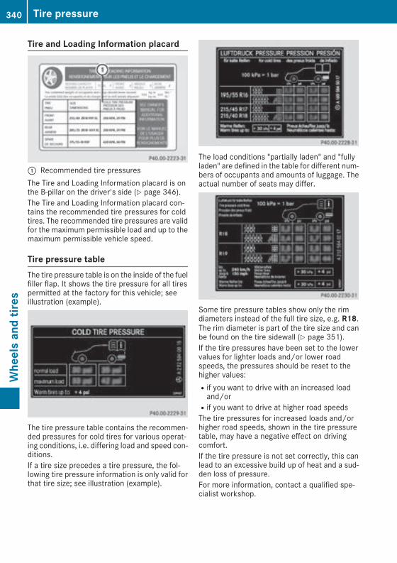
Tire and Loading Information placard
: Recommended tire pressuresThe Tire and Loading Information placard is onthe B-pillar on the driver's side (Y page 346).The Tire and Loading Information placard con-tains the recommended tire pressures for coldtires. The recommended tire pressures are validfor the maximum permissible load and up to themaximum permissible vehicle speed.
Tire pressure tableThe tire pressure table is on the inside of the fuelfiller flap. It shows the tire pressure for all tirespermitted at the factory for this vehicle; seeillustration (example).
The tire pressure table contains the recommen-ded pressures for cold tires for various operat-ing conditions, i.e. differing load and speed con-ditions.If a tire size precedes a tire pressure, the fol-lowing tire pressure information is only valid forthat tire size; see illustration (example).
The load conditions "partially laden" and "fullyladen" are defined in the table for different num-bers of occupants and amounts of luggage. Theactual number of seats may differ.
Some tire pressure tables show only the rimdiameters instead of the full tire size, e.g. R18.The rim diameter is part of the tire size and canbe found on the tire sidewall (Y page 351).If the tire pressures have been set to the lowervalues for lighter loads and/or lower roadspeeds, the pressures should be reset to thehigher values:Rif you want to drive with an increased loadand/orRif you want to drive at higher road speedsThe tire pressures for increased loads and/orhigher road speeds, shown in the tire pressuretable, may have a negative effect on drivingcomfort.If the tire pressure is not set correctly, this canlead to an excessive build up of heat and a sud-den loss of pressure.For more information, contact a qualified spe-cialist workshop.
340 Tire pressureWheelsandtires
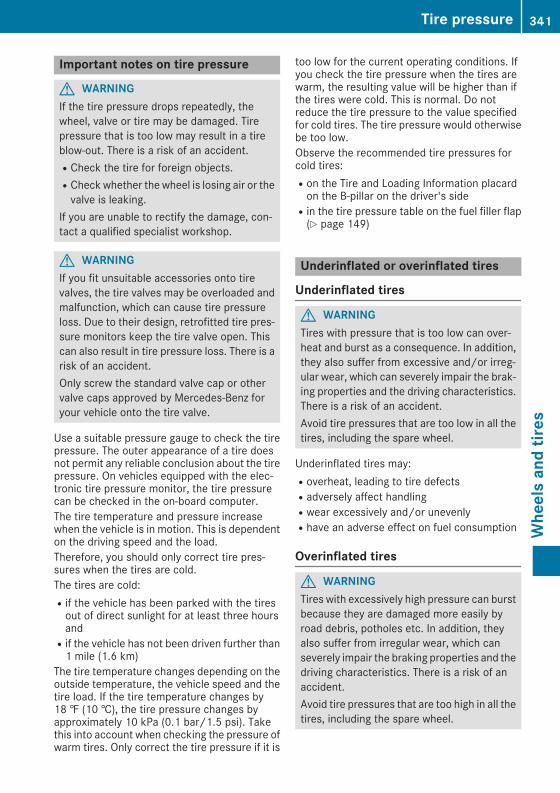
Important notes on tire pressure
G WARNINGIf the tire pressure drops repeatedly, thewheel, valve or tire may be damaged. Tirepressure that is too low may result in a tireblow-out. There is a risk of an accident.RCheck the tire for foreign objects.RCheck whether the wheel is losing air or thevalve is leaking.
If you are unable to rectify the damage, con-tact a qualified specialist workshop.
G WARNINGIf you fit unsuitable accessories onto tirevalves, the tire valves may be overloaded andmalfunction, which can cause tire pressureloss. Due to their design, retrofitted tire pres-sure monitors keep the tire valve open. Thiscan also result in tire pressure loss. There is arisk of an accident.Only screw the standard valve cap or othervalve caps approved by Mercedes-Benz foryour vehicle onto the tire valve.
Use a suitable pressure gauge to check the tirepressure. The outer appearance of a tire doesnot permit any reliable conclusion about the tirepressure. On vehicles equipped with the elec-tronic tire pressure monitor, the tire pressurecan be checked in the on-board computer.The tire temperature and pressure increasewhen the vehicle is in motion. This is dependenton the driving speed and the load.Therefore, you should only correct tire pres-sures when the tires are cold.The tires are cold:Rif the vehicle has been parked with the tiresout of direct sunlight for at least three hoursandRif the vehicle has not been driven further than1 mile (1.6 km)
The tire temperature changes depending on theoutside temperature, the vehicle speed and thetire load. If the tire temperature changes by18 ‡ (10 †), the tire pressure changes byapproximately 10 kPa (0.1 bar/1.5 psi). Takethis into account when checking the pressure ofwarm tires. Only correct the tire pressure if it is
too low for the current operating conditions. Ifyou check the tire pressure when the tires arewarm, the resulting value will be higher than ifthe tires were cold. This is normal. Do notreduce the tire pressure to the value specifiedfor cold tires. The tire pressure would otherwisebe too low.Observe the recommended tire pressures forcold tires:Ron the Tire and Loading Information placardon the B-pillar on the driver's sideRin the tire pressure table on the fuel filler flap(Y page 149)
Underinflated or overinflated tires
Underinflated tires
G WARNINGTires with pressure that is too low can over-heat and burst as a consequence. In addition,they also suffer from excessive and/or irreg-ular wear, which can severely impair the brak-ing properties and the driving characteristics.There is a risk of an accident.Avoid tire pressures that are too low in all thetires, including the spare wheel.
Underinflated tires may:Roverheat, leading to tire defectsRadversely affect handlingRwear excessively and/or unevenlyRhave an adverse effect on fuel consumption
Overinflated tires
G WARNINGTires with excessively high pressure can burstbecause they are damaged more easily byroad debris, potholes etc. In addition, theyalso suffer from irregular wear, which canseverely impair the braking properties and thedriving characteristics. There is a risk of anaccident.Avoid tire pressures that are too high in all thetires, including the spare wheel.
Tire pressure 341
Wheelsandtires
Z

Overinflated tires may:Rincrease the braking distanceRadversely affect handlingRwear excessively and/or unevenlyRhave an adverse effect on ride comfortRbe more susceptible to damage
Maximum tire pressures
: Example: maximum permissible tire pres-sure
Never exceed the maximum permissible tireinflation pressure. Always observe the recom-mended tire pressure for your vehicle whenadjusting the tire pressure (Y page 339).
i The actual values for tires are vehicle-spe-cific and may deviate from the values in theillustration.
Checking the tire pressures
Important safety notesObserve the notes on tire pressure(Y page 339).Information on air pressure for the tires on yourvehicle can be found:Ron the vehicle's Tire and Loading Informationplacard on the B-pillarRin the tire pressure table in the fuel filler flap(Y page 149)Rin the "Tire pressure" section
Checking tire pressures manuallyTo determine and set the correct tire pressure,proceed as follows:X Remove the valve cap of the tire that is to bechecked.
X Press the tire pressure gauge securely ontothe valve.
X Read the tire pressure and compare it to therecommended value on the Tire and LoadingInformation placard or the tire pressure table(Y page 339).
X If the tire pressure is too low, increase the tirepressure to the recommended value.
X If the tire pressure is too high, release air. Todo so, press down the metal pin in the valve,using the tip of a pen for example. Then checkthe tire pressure again using the tire pressurechecker.
X Screw the valve cap onto the valve.X Repeat these steps for the other tires.
Tire pressure loss warning system
General notesWhile the vehicle is in motion, the tire pressureloss warning system monitors the set tire pres-sure using the rotational speed of the wheels.This enables the system to detect significantpressure loss in a tire. If the speed of rotation ofa wheel changes as a result of a loss of pressure,a corresponding warningmessage will appear inthe multifunction display.You can recognize the tire pressure losswarningby the Run Flat Indicator Active Press'OK' to Restart message which appears inthe Service menu of the multifunction display.Information on the message display can befound in the "Restarting the tire pressure losswarning system" section (Y page 343).
Important safety notesThe tire pressure warning system does not warnyou of an incorrectly set tire pressure. Observethe notes on the recommended tire pressure(Y page 339).The tire pressure loss warning does not replacethe need to regularly check the tire pressure. Aneven loss of pressure on several tires at the
342 Tire pressureWheelsandtires

same time cannot be detected by the tire pres-sure loss warning system.The tire pressuremonitor is not able to warn youof a sudden loss of pressure, e.g. if the tire ispenetrated by a foreign object. In the event of asudden loss of pressure, bring the vehicle to ahalt by braking carefully. Avoid abrupt steeringmovements.The function of the tire pressure loss warningsystem is limited or delayed if:Rsnow chains are mounted on your vehicle'stires.Rroad conditions are wintry.Ryou are driving on sand or gravel.Ryou adopt a very sporty driving style (corner-ing at high speeds or driving with high rates ofacceleration).Ryou are towing a very heavy or large trailer.Ryou are driving with a heavy load (in the vehi-cle or on the roof).
Restarting the tire pressure loss warn-ing systemRestart the tire pressure loss warning system ifyou have:Rchanged the tire pressureRchanged the wheels or tiresRmounted new wheels or tiresX Before restarting, make sure that the tirepressures are set properly on all four tires forthe respective operating conditions.The recommended tire pressure can be foundon the Tire and Loading Information placardon the B-pillar. Additionally, a tire pressuretable is attached to the fuel filler flap. The tirepressure loss warning system can only givereliable warnings if you have set the correcttire pressure. If an incorrect tire pressure isset, these incorrect values will be monitored.
X Also observe the notes in the section on tirepressures (Y page 339).
X Make sure that the SmartKey is in position2in the ignition lock (Y page 132).
X Pressò on the steering wheel to call upthe menu list.
X Press9 or: on the steering wheel toselect the Service menu.
X Confirm by pressinga on the steeringwheel.
X Press9 or: to select Tire Pres‐sure.X Pressa to confirm.The Run Flat Indicator Active Press'OK' to Restart message is shown in themultifunction display.
If you wish to confirm the restart:X Press thea button.The Tire Pressure Now OK? message isshown on the multifunction display.
X Press9 or: to select Yes.X Pressa to confirm.The Run Flat Indicator Restarted mes-sage is shown on the multifunction display.After a teach-in period, the tire pressure losswarning system will monitor the set tire pres-sures of all four tires.
If you wish to cancel the restart:X Press the% button.orX If the Tire Pressure Now OK? messageappears, press9 or: to select Can‐cel.
X Pressa to confirm.The tire pressure values stored at the lastrestart will continue to be monitored.
Tire pressure monitor
General notesIf a tire pressure monitor is installed, the vehi-cle's wheels have sensors that monitor the tirepressures in all four tires. The tire pressuremon-itor warns you if the pressure drops in one ormore of the tires. The tire pressure monitor onlyfunctions if the corresponding sensors areinstalled in all wheels.Information on tire pressures is displayed in themultifunction display. After a few minutes ofdriving, the current tire pressure of each tire isshown in the Servicemenu of themultifunctiondisplay; see illustration (example).
Tire pressure 343
Wheelsandtires
Z

Information on the message display can befound in the "Checking the tire pressure elec-tronically" section (Y page 345).
Important safety notes
G WARNINGEach tire, including the spare (if provided),should be checked at least once every twoweeks when cold and inflated to the pressurerecommended by the vehicle manufactureron the Tire and Loading Information placardon the driver's door B-pillar or the tire pres-sure label on the inside of the fuel filler flap. Ifyour vehicle has tires of a different size thanthe size indicated on the Tire and LoadingInformation placard or, if available, the tirepressure label, you should determine theproper tire pressure for those tires.As an added safety feature, your vehicle hasbeen equippedwith a tire pressuremonitoringsystem (TPMS) that illuminates a low tire pres-sure telltale when one or more of your tiresare significantly underinflated. Accordingly,when the low tire pressure telltale lights up,you should stop and check your tires as soonas possible, and inflate them to the properpressure. Driving on a significantly underin-flated tire causes the tire to overheat and canlead to tire failure.Underinflation also reduces fuel efficiencyand tire tread life, andmay affect the vehicle'shandling and stopping ability. Please note thatthe TPMS is not a substitute for proper tiremaintenance, and it is the driver's responsi-bility to maintain correct tire pressure, even ifunderinflation has not reached the level to
trigger illumination of the TPMS low tire pres-sure telltale.Your vehicle has also been equipped with aTPMS malfunction indicator to indicate whenthe system is not operating properly. TheTPMS malfunction indicator is combined withthe low tire pressure telltale. When the sys-tem detects a malfunction, the warning lampwill flash for approximately a minute and thenremain continuously illuminated. Thissequencewill be repeated every time the vehi-cle is started as long as the malfunctionexists. When the malfunction indicator is illu-minated, the systemmay not be able to detector signal low tire pressure as intended.TPMS malfunctions may occur for a variety ofreasons, including the installation of incom-patible replacement or alternate tires orwheels on the vehicle that prevent the TPMSfrom functioning properly. Always check theTPMS malfunction telltale after replacing oneor more tires or wheels on your vehicle toensure that the replacement or alternate Tiresand wheels allow the TPMS to continue tofunction properly.
It is the driver's responsibility to set the tirepressure to that recommended for cold tireswhich is suitable for the operating situation(Y page 339). Note that the correct tire pressurefor the current operating situation must first betaught-in to the tire pressure monitor. If a sub-stantial loss of pressure occurs, the warningthreshold for the warning message is aligned tothe taught-in reference values. Restart the tirepressuremonitor after adjusting the pressure ofthe cold tires (Y page 345). The current pres-sures are saved as new reference values. As aresult, a warning message will appear if the tirepressure drops significantly.The tire pressure monitor does not warn you ofan incorrectly set tire pressure. Observe thenotes on the recommended tire pressure(Y page 339).The tire pressuremonitor is not able to warn youof a sudden loss of pressure, e.g. if the tire ispenetrated by a foreign object. In the event of asudden loss of pressure, bring the vehicle to ahalt by braking carefully. Avoid abrupt steeringmovements.
344 Tire pressureWheelsandtires

The tire pressure monitor has a yellow warninglamp in the instrument cluster for indicatingpressure loss or a malfunction. Whether thewarning lamp flashes or lights up indicateswhether a tire pressure is too low or the tirepressure monitor is malfunctioning:Rif the warning lamp is lit continuously, the tirepressure on one or more tires is significantlytoo low. The tire pressure monitor is not mal-functioning.Rif the warning lamp flashes for around aminute and then remains lit constantly, thetire pressure monitor is malfunctioning.
In addition to the warning lamp, a messageappears in the multifunction display. Observethe information on display messages(Y page 250).It may take up to ten minutes for a malfunctionof the tire pressure monitor to be indicated. Amalfunction will be indicated by the tire pres-sure warning lamp flashing for approximatelyone minute and then remaining lit. When themalfunction has been rectified, the tire pressurewarning lamp goes out after a few minutes ofdriving.The tire pressure values indicated by the on-board computer may differ from those meas-ured at a gas station with a pressure gauge. Thetire pressures shown by the on-board computerrefer to those measured at sea level. At highaltitudes, the tire pressure values indicated by apressure gauge are higher than those shown bythe on-board computer. In this case, do notreduce the tire pressures.The operation of the tire pressure monitor canbe affected by interference from radio transmit-ting equipment (e.g. radio headphones, two-wayradios) thatmay be being operated in or near thevehicle.
Checking the tire pressure electroni-callyX Make sure that the SmartKey is in position2(Y page 132) in the ignition lock.
X Pressò on the steering wheel to call upthe menu list.
X Press9 or: on the steering wheel toselect the Service menu.
X Confirm by pressinga on the steeringwheel.
X Press9 or: to select Tire Pres‐sure.X Pressa to confirm.The multifunction display shows the currenttire pressure of each wheel.
If the vehicle was parked for longer than20 minutes, the following message appears:Tire pressure will be displayed afterdriving a few minutes.After a teach-in process, the tire pressure mon-itor automatically detects new wheels or newsensors. As long as a clear allocation of the tirepressure value to the individual wheels is notpossible, the Tire Pressure Monitor Activemessage is shown instead of the tire pressuredisplay. The tire pressures are already beingmonitored.
Tire pressure monitor warning mes-sagesIf the tire pressure monitor detects a pressureloss in one or more tires, a warning message isshown in the multifunction display. The yellowtire pressure warning lamp then lights up.RIf the Please Correct Tire Pressuremessage appears in themultifunction display,the tire pressure in at least one tire is too low.The tire pressure must be corrected when theopportunity arises.RIf the Check Tires message appears in themultifunction display, the tire pressure in oneor more tires has dropped significantly. Thetires must be checked.RIf the Warning Tire Malfunctionmessageappears in the multifunction display, the tirepressure in one or more tires has droppedsuddenly. The tires must be checked.
Be sure to observe the instructions and safetynotes in the display messages in the "Tires" sec-tion (Y page 250).If the wheel positions on the vehicle are rotated,the tire pressures may be displayed for thewrong positions for a short time. This is rectifiedafter a few minutes of driving, and the tire pres-sures are displayed for the correct positions.
Restarting the tire pressure monitorWhen you restart the tire pressure monitor, allexisting warning messages are deleted and thewarning lamps go out. Themonitor uses the cur-rently set tire pressures as the reference values
Tire pressure 345
Wheelsandtires
Z

for monitoring. In most cases, the tire pressuremonitor will automatically detect the new refer-ence values after you have changed the tirepressure. However, you can also set referencevalues manually as described here. The tirepressure monitor then monitors the new tirepressure values.X Set the tire pressure to the value recommen-ded for the corresponding driving situation onthe Tire and Loading Information placard onthe B-pillar on the driver's side.You can find more tire pressures for variousoperating conditions in the tire pressure tableinside the filler flap.Observe the information on tire pressurewhen doing so (Y page 339).
X Make sure that the tire pressure is correct onall four wheels.
X Make sure that the SmartKey is in position2in the ignition lock (Y page 132).
X Pressò on the steering wheel to call upthe menu list.
X Press9 or: on the steering wheel toselect the Service menu.
X Confirm by pressinga on the steeringwheel.
X Press9 or: to select Tire Pres‐sure.X Pressa to confirm.The multifunction display shows the currenttire pressure of each wheel or the Tirepressure will be displayed afterdriving a few minutes message.
X Press the: button.The Use Current Pressures as New Ref‐erence Values message is shown on themultifunction display.
If you wish to confirm the restart:X Press thea button.The Tire Press. Monitor Restartedmes-sage is shown on the multifunction display.After driving for a few minutes, the systemchecks whether the current tire pressures arewithin the specified range. The new tire pres-sures are then accepted as reference valuesand monitored.
If you wish to cancel the restart:X Press the% button.The tire pressure values stored at the lastrestart will continue to be monitored.
Radio type approval for the tire pres-sure monitor
Country Radio type approval number
USA FCC ID: MRXGG4FCC ID: MRXMC34MA4
Canada IC: 2546A-GG4
Loading the vehicle
Instruction labels for tires and loads
G WARNINGOverloaded tires can overheat, causing ablowout. Overloaded tires can also impair thesteering and driving characteristics and leadto brake failure. There is a risk of accident.Observe the load rating of the tires. The loadrating must be at least half of the GAWR ofyour vehicle. Never overload the tires byexceeding the maximum load.
Two instruction labels on your vehicle show themaximum possible load.(1) The Tire and Loading Information placard is
on the B-pillar on the driver's side. The Tireand Loading Information placard shows themaximum permissible number of occu-pants and themaximumpermissible vehicleload. It also contains details of the tire sizesand corresponding pressures for tiresmounted at the factory.
(2) The vehicle identification plate is on the B-pillar on the driver's side. The vehicle iden-tification plate informs you of the grossvehicle weight rating. It is made up of thevehicle weight, all vehicle occupants, thefuel and the cargo. You can also find infor-mation about the maximum gross axleweight rating on the front and rear axle.The maximum gross axle weight rating isthe maximum weight that can be carried byone axle (front or rear axle). Never exceedthe maximum load or the maximum grossaxle weight rating for the front or rear axle.
346 Loading the vehicleWheelsandtires

: B-pillar, driver's side
Maximum permissible gross vehicleweight rating
X Specification for maximum gross vehicleweight: is listed in the Tire and LoadingInformation placard: "The combinedweight ofoccupants and cargo should never exceedXXX kg or XXX lbs."
The gross weight of all vehicle occupants, loadand luggage must not exceed the specifiedvalue.
i The specifications shown on the Tire andLoading Information placard in the illustrationare examples. The maximum permissiblegross vehicle weight rating is vehicle-specificand may differ from that in the illustration.You can find the valid maximum permissiblegross vehicle weight rating for your vehicle onthe Tire and Loading Information placard.
Number of seats
Maximum number of seats: indicates themaximum number of occupants allowed totravel in the vehicle. This information can befound on the Tire and Loading Information plac-ard.
i The specifications shown on the Tire andLoading Information placard in the illustrationare examples. The number of seats is vehicle-specific and can differ from the details shown.The number of seats in your vehicle can befound on the Tire and Loading Informationplacard.
Determining the correct load limit
Step-by-step instructionsThe following steps have been developed asrequired of all manufacturers under Title 49,Code of U.S. Federal Regulations, Part 575 pur-suant to the "National Traffic and Motor VehicleSafety Act of 1966".X Step 1: Locate the statement "The combinedweight of occupants and cargo should neverexceed XXX kg or XXX lbs." on your vehicle'sTire and Loading Information placard.
X Step 2: Determine the combined weight ofthe driver and passengers that will be riding inyour vehicle.
X Step 3: Subtract the combined weight of thedriver and passengers from XXX kilograms orXXX lbs.
X Step 4: The resulting figure equals the avail-able amount of cargo and luggage load capa-city. For example, if the "XXX" amount equals1400 lbs and there will be five 150-lb pas-sengers in your vehicle, the amount of avail-
Loading the vehicle 347
Wheelsandtires
Z

able cargo and luggage load capacity is650 lbs (1400 - 750 (5 x 150) = 650 lbs).
X Step 5: Determine the combined weight ofluggage and cargo being loaded on the vehi-
cle. That weight may not safely exceed theavailable cargo and luggage load capacity cal-culated in step 4.
Example: steps 1 to 3The following table shows examples on how to calculate total and cargo load capacities with varyingseating configurations and number and size of occupants. The following examples use a load limit of1500 lbs (680 kg). This is for illustration purposes only.Make sure you are using the actual loadlimit for your vehicle stated on your vehicle's Tire and Loading Information placard (Y page 346).The greater the combined weight of the occupants, the lower the maximum luggage load.Step 1
Example 1 Example 2 Example 3
Combined maximumweight of occupantsand load (data from theTire and Loading Infor-mation placard)
1500 lbs (680 kg) 1500 lbs (680 kg) 1500 lbs (680 kg)
Step 2
Example 1 Example 2 Example 3
Number of people inthe vehicle (driver andoccupants)
5 3 1
Distribution of theoccupants
Front: 2Rear: 3
Front: 1Rear: 2
Front: 1
Weight of the occu-pants
Occupant 1: 150 lbs(68 kg)Occupant 2: 180 lbs(82 kg)Occupant 3: 160 lbs(73 kg)Occupant 4: 140 lbs(63 kg)Occupant 5: 120 lbs(54 kg)
Occupant 1: 200 lbs(91 kg)Occupant 2: 190 lbs(86 kg)Occupant 3: 150 lbs(68 kg)
Occupant 1: 150 lbs(68 kg)
Gross weight of alloccupants
750 lbs (340 kg) 540 lbs (245 kg) 150 lbs (68 kg)
348 Loading the vehicleWheelsandtires
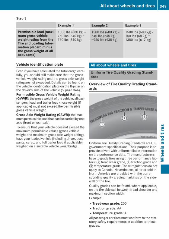
Step 3
Example 1 Example 2 Example 3
Permissible load (maxi-mum gross vehicleweight rating from theTire and Loading Infor-mation placard minusthe gross weight of alloccupants)
1500 lbs (680 kg) Ò750 lbs (340 kg) =750 lbs (340 kg)
1500 lbs (680 kg) Ò540 lbs (245 kg)=960 lbs (435 kg)
1500 lbs (680 kg) Ò150 lbs (68 kg) =1350 lbs (612 kg)
Vehicle identification plateEven if you have calculated the total cargo care-fully, you should still make sure that the grossvehicle weight rating and the gross axle weightrating are not exceeded. Details can be found onthe vehicle identification plate on the B-pillar onthe driver's side of the vehicle (Y page 346).Permissible Gross Vehicle Weight Rating(GVWR): the gross weight of the vehicle, all pas-sengers, load and trailer load/noseweight (ifapplicable) must not exceed the permissiblegross vehicle weight.Gross Axle Weight Rating (GAWR): the maxi-mumpermissible load that can be carried by oneaxle (front or rear axle).To ensure that your vehicle does not exceed themaximum permissible values (gross vehicleweight and maximum gross axle weight rating),have your loaded vehicle (including driver, occu-pants, cargo, and full trailer load if applicable)weighed on a suitable vehicle weighbridge.
All about wheels and tires
Uniform Tire Quality Grading Stand-ards
Overview of Tire Quality Grading Stand-ards
Uniform Tire Quality Grading Standards are U.S.government specifications. Their purpose is toprovide drivers with uniform reliable informationon tire performance data. Tire manufacturershave to grade tires using three performance fac-tors:: tread wear grade,; traction grade and= temperature grade. These regulations do notapply to Canada. Nevertheless, all tires sold inNorth America are provided with the corre-sponding quality grading markings on the side-wall of the tire.Quality grades can be found, where applicable,on the tire sidewall between tread shoulder andmaximum section width.Example:RTreadwear grade: 200RTraction grade: AARTemperature grade: AAll passenger car tiresmust conform to the stat-utory safety requirements in addition to thesegrades.
All about wheels and tires 349
Wheelsandtires
Z

i The actual values for tires are vehicle-spe-cific and may deviate from the values in theillustration.
TreadwearThe treadwear grade is a comparative ratingbased on the wear rate of the tire when testedunder controlled conditions on a specified U.S.government course. For example, a tire graded150 would wear one and one-half times as wellon the government course as a tire graded 100.The relative performance of tires depends uponthe actual conditions of their use, however, andmay depart significantly from the norm due tovariations in driving habits, service practicesand differences in road characteristics and cli-mate.
Traction
G WARNINGThe traction grade assigned to this tire isbased on straight-ahead braking tractiontests, and does not include acceleration, cor-nering, hydroplaning, or peak traction char-acteristics.
! Avoid wheelspin. This can lead to damage tothe drive train.
The traction grades – from highest to lowest –are AA, A, B and C. Those grades represent thetire's ability to stop on wet pavement as meas-ured under controlled conditions on specifiedgovernment test surfaces of asphalt and con-crete. A tire marked C may have poor tractionperformance.The safe speed on a wet, snow covered or icyroad is always lower than on dry road surfaces.You should pay special attention to road condi-tions when temperatures are around freezingpoint.Mercedes-Benz recommends a minimum treaddepth ofã in (4 mm) on all four winter tires.Observe the legally required minimum tire treaddepth (Y page 337). Winter tires can reduce thebraking distance on snow-covered surfaces incomparison with summer tires. The braking dis-tance is still much further than on surfaces thatare not icy or covered with snow. Take appro-priate care when driving.
Further information on winter tires (M+S tires)(Y page 338).
Temperature
G WARNINGThe temperature grade for this tire is estab-lished for a tire that is properly inflated andnot overloaded. Excessive speed, underinfla-tion, or excessive loading, either separately orin combination, can cause excessive heatbuild-up and possible tire failure.
The temperature grades are A (the highest), B,and C, representing the tire's resistance to thegeneration of heat and its ability to dissipateheat when tested under controlled conditionson a specified indoor laboratory test wheel. Sus-tained high temperature can cause the materialof the tire to degenerate and reduce tire life, andexcessive temperature can lead to sudden tirefailure. The grade C corresponds to a level ofperformance which all passenger car tires mustmeet under the Federal Motor Vehicle SafetyStandard No. 109. Grades B and A representhigher levels of performance on the laboratorytest wheel than the minimum required by law.
350 All about wheels and tiresWheelsandtires

Tire labeling
Overview
: Uniform Tire Quality Grading Standard(Y page 354)
; DOT, Tire Identification Number(Y page 353)
= Maximum tire load (Y page 353)? Maximum tire pressure (Y page 342)A ManufacturerB Tire material (Y page 354)C Tire size designation, load-bearing capacity
and speed rating (Y page 351)D Load index (Y page 353)E Tire nameThe markings described above are on the tire inaddition to the tire name (sales designation) andthe manufacturer's name.
i Tire data is vehicle-specific and may deviatefrom the data in the example.
Tire size designation, load-bearingcapacity and speed rating
G WARNINGExceeding the stated tire load-bearing capa-city and the approved maximum speed couldlead to tire damage or the tire bursting. Thereis a risk of accident.Therefore, only use tire types and sizesapproved for your vehicle model. Observe the
tire load rating and speed rating required foryour vehicle.
: Tire width; Nominal aspect ratio in %= Tire code? Rim diameterA Load bearing indexB Speed ratingGeneral: depending on the manufacturer'sstandards, the size imprinted in the tire wall maynot contain any letters or may contain one letterthat precedes the size description.If there is no letter preceding the size descrip-tion (as shown above): these are passengervehicle tires according to European manufac-turing standards.If "P" precedes the size description: these arepassenger vehicle tires according to U.S. man-ufacturing standards.If "LT" precedes the size description: these arelight truck tires according to U.S. manufacturingstandards.If "T" precedes the size description: compactemergency wheels with high tire pressure thatare only designed for temporary use in an emer-gency.Tire width:tire width: shows the nominal tirewidth in millimeters.Height-width ratio: aspect ratio; is the sizeratio between the tire height and tire width andis shown in percent. The aspect ratio is calcula-ted by dividing the tire width by the tire height.Tire code:tire code= specifies the tire type."R" represents radial tires; "D" represents diag-onal tires; "B" represents diagonal radial tires.Optionally, tires with a maximum speed of over149 mph (240 km/h) may have "ZR" in the size
All about wheels and tires 351
Wheelsandtires
Z

description, depending on the manufacturer(e.g. 245/40 ZR 18).Rim diameter: rim diameter? is the diameterof the bead seat, not the diameter of the rimflange. The rim diameter is specified ininches (in).Load-bearing index: load-bearing indexA is anumerical code that specifies the maximumload-bearing capacity of a tire.Do not overload the tires by exceeding thespecified load limit. The maximum permissibleload can be found on the vehicle's Tire andLoading Information placard on the B-pillar onthe driver's side (Y page 346).Example:Load-bearing index 91 indicates a maximumload of 1,356 lb (615 kg) that the tires can bear.For further information on the maximum tireload in kilograms and lbs, see (Y page 353).For further information on the load bearingindex, see "Load index" (Y page 353).Speed rating:speed ratingB specifies theapproved maximum speed of the tire.
i Tire data is vehicle-specific and may deviatefrom the data in the example.
Regardless of the speed rating, always observethe speed limits. Drive carefully and adapt yourdriving style to the traffic conditions.Summer tires
Index Speed rating
Q up to 100 mph (160 km/h)
R up to 106 mph (170 km/h)
S up to 112 mph (180 km/h)
T up to 118 mph (190 km/h)
H up to 130 mph (210 km/h)
V up to 149 mph (240 km/h)
W up to 168 mph (270 km/h)
Y up to 186 mph (300 km/h)
ZR...Y up to 186 mph (300 km/h)
ZR...(..Y) over 186 mph (300 km/h)
ZR over 149 mph (240 km/h)
ROptionally, tires with a maximum speed ofover 149 mph (240 km/h) may have "ZR" inthe size description, depending on the man-ufacturer (e.g. 245/40 ZR18).The service specification is made up of load-bearing indexA and speed ratingB.RIf the size description of your tire includes"ZR" and there are no service specifications,ask the tire manufacturer in order to find outthe maximum speed.If a service specification is available, the max-imum speed is limited according to the speedrating in the service specification. Example:245/40 ZR18 97 Y. In this example, "97 Y" isthe service specification. The letter "Y" rep-resents the speed rating. The maximumspeed of the tire is limited to 186 mph(300 km/h).RThe size description for all tires with maxi-mum speeds of over 186 mph (300 km/h)must include "ZR",and the service specifica-tion must be given in parentheses. Example:275/40 ZR 18 (99 Y). Speed rating "(Y)" indi-cates that the maximum speed of the tire isover 186 mph (300 km/h). Ask the tire man-ufacturer about the maximum speed.
All-weather tires and winter tires
Index Speed rating
Q M+S1 up to 100 mph (160 km/h)
T M+S1 up to 118 mph (190 km/h)
H M+S1 up to 130 mph (210 km/h)
V M+S1 up to 149 mph (240 km/h)
i Not all tires with the M+S marking providethe driving characteristics of winter tires. Inaddition to theM+Smarking, winter tires alsohave thei snowflake symbol on the tirewall. Tires with this marking fulfill the require-ments of the Rubber Manufacturers Associa-tion (RMA) and the Rubber Association ofCanada (RAC) regarding the tire traction onsnow. They have been especially developedfor driving on snow.
An electronic speed limiter prevents your vehi-cle from exceeding a speed of 130 mph(210 km/h).
1 Or M+Si for winter tires.
352 All about wheels and tiresWheelsandtires

The speed rating of tires mounted at the factorymay be higher than themaximum speed that theelectronic speed limiter permits.Make sure that your tires have the requiredspeed rating, e.g. when buying new tires. Youcan find information on this under "Tires"(Y page 360).Further information about reading tire data canbe obtained from any qualified specialist work-shop.
Load index
In addition to the load-bearing index, loadindex: may also be imprinted on the sidewallof the tire. You will find this after the letter thatidentifies the speed rating (Y page 351).RIf no specification is given: no text (as in theexample above), represents a standard load(SL) tireRXL or Extra Load: represents a reinforced tireRLight Load: represents a light load tireRC, D, E: represents a load range that dependson themaximum load that the tire can carry ata certain pressure
i Tire data is vehicle-specific and may deviatefrom the data in the example.
Maximum load rating
Maximum tire load: is the maximum permis-sible weight for which the tire is approved.Do not overload the tires by exceeding thespecified load limit. The maximum permissibleload can be found on the vehicle's Tire andLoading Information placard on the B-pillar onthe driver's side (Y page 346).
i The actual values for tires are vehicle-spe-cific and may deviate from the values in theillustration.
DOT, Tire Identification Number (TIN)US tire regulations stipulate that every tire man-ufacturer or retreadermust imprint a TIN in or onthe sidewall of each tire produced.
The TIN is a unique identification number. TheTIN enables the tiremanufacturers or retreadersto inform purchasers of recalls and other safety-relevant matters. It makes it possible for thepurchaser to easily identify the affected tires.The TIN is made up of manufacturer identifica-tion code;, tire size=, tire type code? andmanufacturing dateA.DOT (Department of Transportation): tiresymbol:marks that the tire complies with the
All about wheels and tires 353
Wheelsandtires
Z

requirements of the U.S. Department of Trans-portation.Manufacturer identification code: manufac-turer identification code; provides details onthe tire manufacturer. New tires have a codewith two symbols. Retreaded tires have a codewith four symbols.For further information about retreaded tires,see (Y page 360).Tire size: identifier= describes the tire size.Tire type code: tire type code? can be used bythe manufacturer as a code to describe specificcharacteristics of the tire.Date of manufacture: date of manufactureAprovides information about the age of a tire. Thefirst and second positions represent the week ofmanufacture, starting with "01" for the first cal-endar week. Positions three and four representthe year of manufacture. For example, a tire thatis marked "3214" wasmanufactured in week 32in 2014.
i Tire data is vehicle-specific and may deviatefrom the data in the example.
Tire characteristics
This information describes the type of tire cordand the number of layers in sidewall: andunder tire tread;.
i Tire data is vehicle-specific and may deviatefrom the data in the example.
Definition of terms for tires and loading
Tire ply composition and material usedDescribes the number of plies or the number oflayers of rubber-coated fabric in the tire treadand sidewall. These are made of steel, nylon,polyester and other materials.
BarMetric unit for tire pressure. 14.5038 poundsper square inch (psi) and 100 kilopascals (kPa)are the equivalent of 1 bar.
DOT (Department of Transportation)DOT-marked tires fulfill the requirements of theU S Department of Transportation.
Normal occupant weightThe number of occupants for which the vehicleis designedmultiplied by 68 kilograms (150 lbs).
Uniform Tire Quality Grading StandardsA uniform standard to grade the quality of tireswith regards to tread quality, tire traction andtemperature characteristics. The quality grad-ing assessment is made by the manufacturerfollowing specifications from the U.S. govern-ment. The ratings aremolded into the sidewall ofthe tire.
Recommended tire pressuresThe recommended tire pressure applies to thetires mounted at the factory.The Tire and Loading Information placard con-tains the recommended tire pressures for coldtires on a fully loaded vehicle and for the maxi-mum permissible vehicle speed.The tire pressure table contains the recommen-ded pressures for cold tires for various operat-ing conditions, i.e. differing load and speed con-ditions.
Increased vehicle weight due to optionalequipmentThe combined weight of all standard andoptional equipment available for the vehicle,regardless of whether it is actually installed onthe vehicle or not.
RimThis is the part of the wheel on which the tire ismounted.
GAWR (Gross Axle Weight Rating)The GAWR is the maximum gross axle weightrating. The actual load on an axle must neverexceed the gross axle weight rating. The grossaxle weight rating can be found on the vehicleidentification plate on the B-pillar on the driver'sside.
354 All about wheels and tiresWheelsandtires

Speed ratingThe speed rating is part of the tire identification.It specifies the speed range for which the tire isapproved.
GVW (Gross Vehicle Weight)The gross vehicle weight includes the weight ofthe vehicle including fuel, tools, the sparewheel,accessories installed, occupants, luggage andthe drawbar noseweight, if applicable. The grossvehicle weight must not exceed the gross vehi-cle weight rating GVWR as specified on the vehi-cle identification plate on the B-pillar on thedriver's side.
GVWR (Gross Vehicle Weight Rating)The GVWR is the maximum permissible grossweight of a fully loaded vehicle (theweight of thevehicle including all accessories, occupants,fuel, luggage and the drawbar noseweight, ifapplicable). The gross vehicle weight rating isspecified on the vehicle identification plate onthe B-pillar on the driver's side.
Maximum loaded vehicle weightThe maximum weight is the sum of:Rthe curb weight of the vehicleRthe weight of the accessoriesRthe load limitRthe weight of the factory installed optionalequipment
Kilopascal (kPa)Metric unit for tire pressure. 6.9 kPa corre-sponds to 1 psi. Another unit for tire pressure isbar. 100 kilopascals (kPa) are the equivalent of1 bar.
Load indexIn addition to the load-bearing index, the loadindex may also be imprinted on the sidewall ofthe tire. This specifies the load-bearing capacitymore precisely.
Curb weightTheweight of a vehicle with standard equipmentincluding the maximum capacity of fuel, oil andcoolant. It also includes the air-conditioning sys-tem and optional equipment if these are instal-led in the vehicle, but does not include passen-gers or luggage.
Maximum load ratingThe maximum tire load is the maximum permis-sible weight in kilograms or lbs for which a tire isapproved.
Maximum permissible tire pressureMaximum permissible tire pressure for one tire.
Maximum load on one tireMaximum load on one tire. This is calculated bydividing the maximum axle load of one axle bytwo.
PSI (pounds per square inch)A standard unit of measure for tire pressure.
Aspect ratioRelationship between tire height and tire widthin percent.
Tire pressureThis is pressure inside the tire applying an out-ward force to each square inch of the tire's sur-face. The tire pressure is specified in pounds persquare inch (psi), in kilopascal (kPa) or in bar.The tire pressure should only be corrected whenthe tires are cold.
Cold tire pressureThe tires are cold:Rif the vehicle has been parked with the tiresout of direct sunlight for at least three hoursandRif the vehicle has not been driven further than1 mile (1.6 km)
TreadThe part of the tire that comes into contact withthe road.
BeadThe tire bead ensures that the tire sits securelyon thewheel. There are several steel wires in thebead to prevent the tire from coming loose fromthe wheel rim.
SidewallThe part of the tire between the tread and thebead.
All about wheels and tires 355
Wheelsandtires
Z
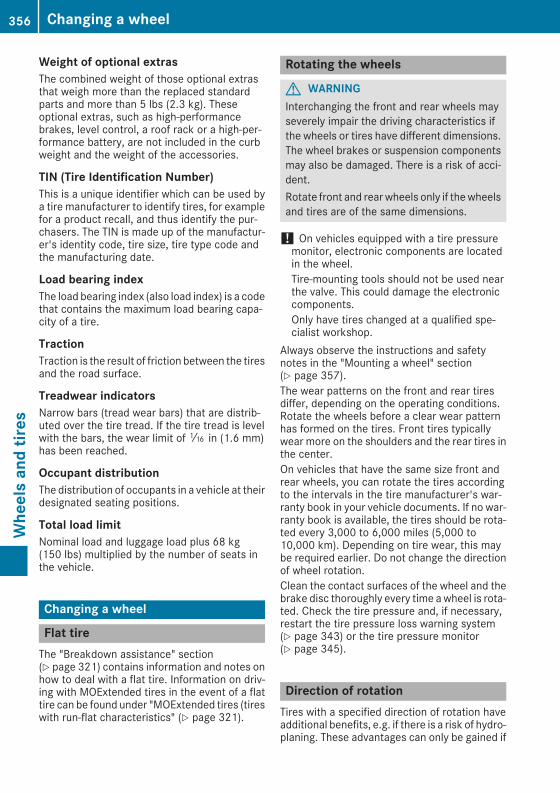
Weight of optional extrasThe combined weight of those optional extrasthat weigh more than the replaced standardparts and more than 5 lbs (2.3 kg). Theseoptional extras, such as high-performancebrakes, level control, a roof rack or a high-per-formance battery, are not included in the curbweight and the weight of the accessories.
TIN (Tire Identification Number)This is a unique identifier which can be used bya tire manufacturer to identify tires, for examplefor a product recall, and thus identify the pur-chasers. The TIN is made up of the manufactur-er's identity code, tire size, tire type code andthe manufacturing date.
Load bearing indexThe load bearing index (also load index) is a codethat contains the maximum load bearing capa-city of a tire.
TractionTraction is the result of friction between the tiresand the road surface.
Treadwear indicatorsNarrow bars (tread wear bars) that are distrib-uted over the tire tread. If the tire tread is levelwith the bars, the wear limit ofá in (1.6 mm)has been reached.
Occupant distributionThe distribution of occupants in a vehicle at theirdesignated seating positions.
Total load limitNominal load and luggage load plus 68 kg(150 lbs) multiplied by the number of seats inthe vehicle.
Changing a wheel
Flat tireThe "Breakdown assistance" section(Y page 321) contains information and notes onhow to deal with a flat tire. Information on driv-ing with MOExtended tires in the event of a flattire can be found under "MOExtended tires (tireswith run-flat characteristics" (Y page 321).
Rotating the wheels
G WARNINGInterchanging the front and rear wheels mayseverely impair the driving characteristics ifthe wheels or tires have different dimensions.The wheel brakes or suspension componentsmay also be damaged. There is a risk of acci-dent.Rotate front and rear wheels only if thewheelsand tires are of the same dimensions.
! On vehicles equipped with a tire pressuremonitor, electronic components are locatedin the wheel.Tire-mounting tools should not be used nearthe valve. This could damage the electroniccomponents.Only have tires changed at a qualified spe-cialist workshop.
Always observe the instructions and safetynotes in the "Mounting a wheel" section(Y page 357).The wear patterns on the front and rear tiresdiffer, depending on the operating conditions.Rotate the wheels before a clear wear patternhas formed on the tires. Front tires typicallywear more on the shoulders and the rear tires inthe center.On vehicles that have the same size front andrear wheels, you can rotate the tires accordingto the intervals in the tire manufacturer's war-ranty book in your vehicle documents. If no war-ranty book is available, the tires should be rota-ted every 3,000 to 6,000 miles (5,000 to10,000 km). Depending on tire wear, this maybe required earlier. Do not change the directionof wheel rotation.Clean the contact surfaces of the wheel and thebrake disc thoroughly every time awheel is rota-ted. Check the tire pressure and, if necessary,restart the tire pressure loss warning system(Y page 343) or the tire pressure monitor(Y page 345).
Direction of rotationTires with a specified direction of rotation haveadditional benefits, e.g. if there is a risk of hydro-planing. These advantages can only be gained if
356 Changing a wheelWheelsandtires

the tires are installed corresponding to thedirection of rotation.An arrow on the sidewall of the tire indicates itscorrect direction of rotation.
Storing wheelsStore wheels that are not being used in a cool,dry and preferably dark place. Protect the tiresfrom oil, grease, gasoline and diesel.
Mounting a wheel
Preparing the vehicleX Stop the vehicle on solid, non-slippery andlevel ground.
X Apply the electric parking brake manually.X Bring the front wheels into the straight-aheadposition.
X Shift the transmission to positionj.X Make sure that the vehicle level is set to "Nor-mal" on vehicles with AIR BODY CONTROL(Y page 173).
X Switch off the engine.X Vehicles without KEYLESS-GO: remove theSmartKey from the ignition lock.
X Vehicles with KEYLESS-GO start-functionor KEYLESS-GO: open the driver's door.The vehicle electronics are now in key posi-tionu. This is the same as the key havingbeen removed.
X Vehicles with KEYLESS-GO start-functionor KEYLESS-GO: remove the Start/Stop but-ton from the ignition lock (Y page 133).
X Make sure that the engine cannot be startedvia your smartphone (Y page 134).
X If included in the vehicle equipment, removethe tire-change tool kit from the vehicle.
X Safeguard the vehicle against rolling away.
Securing the vehicle to prevent it fromrolling away
If your vehicle is equipped with a wheel chock, itcan be found in the tire-change tool kit(Y page 320).The folding wheel chock is an additional safetymeasure to prevent the vehicle from rollingaway, for example when changing a wheel.X Fold both plates upwards:.X Fold out lower plate;.X Guide the lugs on the lower plate fully into theopenings in base plate=.
X Place chocks or other suitable items underthe front and rear of the wheel that is diago-nally opposite the wheel you wish to change.
Raising the vehicle
G WARNINGIf you do not position the jack correctly at theappropriate jacking point of the vehicle, thejack could tip over with the vehicle raised.There is a risk of injury.Only position the jack at the appropriate jack-ing point of the vehicle. The base of the jack
Changing a wheel 357
Wheelsandtires
Z

must be positioned vertically, directly underthe jacking point of the vehicle.
! Only position the jack at the appropriatejacking point of the vehicle. Otherwise, youcould damage the vehicle.
Observe the followingwhen raising the vehi-cle:RTo raise the vehicle, only use the vehicle-spe-cific jack that has been tested and approvedby Mercedes-Benz. If used incorrectly, thejack could tip over with the vehicle raised.RThe jack is designed only to raise and hold thevehicle for a short time while a wheel is beingchanged. It must not be used for performingmaintenance work under the vehicle.RAvoid changing the wheel on uphill and down-hill slopes.RBefore raising the vehicle, secure it from roll-ing away by applying the parking brake andinserting wheel chocks. Do not disengage theparking brake while the vehicle is raised.RThe jack must be placed on a firm, flat andnon-slip surface. On a loose surface, a large,flat, load-bearing underlaymust be used. On aslippery surface, a non-slip underlay must beused, e.g. rubber mats.RDo not use wooden blocks or similar objectsas a jack underlay. Otherwise, the jackwill notbe able to achieve its load-bearing capacitydue to the restricted height.RMake sure that the distance between theunderside of the tires and the ground does notexceed 1.2 in (3 cm).RDo not place your hands or feet under theraised vehicle.RDo not lie under the vehicle.RDo not start the engine when the vehicle israised.RNever open or close a door or the tailgatewhen the vehicle is raised.RMake sure that no persons are present in thevehicle when the vehicle is raised.
X Using lug wrench:, loosen the bolts on thewheel you wish to change by about one fullturn. Do not unscrew the bolts completely.
The jacking points are located just behind thefront wheel housings and just in front of the rearwheel housings (arrows).X Take the ratchet wrench out of the tire-chang-ing tool kit and place it on the hexagon nut ofthe jack so that the letters AUF are visible.
X Position jack= at jacking point;.
358 Changing a wheelWheelsandtires
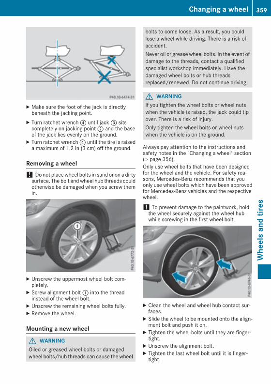
X Make sure the foot of the jack is directlybeneath the jacking point.
X Turn ratchet wrench? until jack= sitscompletely on jacking point; and the baseof the jack lies evenly on the ground.
X Turn ratchet wrench? until the tire is raiseda maximum of 1.2 in (3 cm) off the ground.
Removing a wheel! Do not placewheel bolts in sand or on a dirtysurface. The bolt andwheel hub threads couldotherwise be damaged when you screw themin.
X Unscrew the uppermost wheel bolt com-pletely.
X Screw alignment bolt: into the threadinstead of the wheel bolt.
X Unscrew the remaining wheel bolts fully.X Remove the wheel.
Mounting a new wheel
G WARNINGOiled or greased wheel bolts or damagedwheel bolts/hub threads can cause the wheel
bolts to come loose. As a result, you couldlose a wheel while driving. There is a risk ofaccident.Never oil or greasewheel bolts. In the event ofdamage to the threads, contact a qualifiedspecialist workshop immediately. Have thedamaged wheel bolts or hub threadsreplaced/renewed. Do not continue driving.
G WARNINGIf you tighten the wheel bolts or wheel nutswhen the vehicle is raised, the jack could tipover. There is a risk of injury.Only tighten the wheel bolts or wheel nutswhen the vehicle is on the ground.
Always pay attention to the instructions andsafety notes in the "Changing a wheel" section(Y page 356).Only use wheel bolts that have been designedfor the wheel and the vehicle. For safety rea-sons, Mercedes-Benz recommends that youonly use wheel bolts which have been approvedfor Mercedes-Benz vehicles and the respectivewheel.
! To prevent damage to the paintwork, holdthe wheel securely against the wheel hubwhile screwing in the first wheel bolt.
X Clean the wheel and wheel hub contact sur-faces.
X Slide the wheel to be mounted onto the align-ment bolt and push it on.
X Tighten the wheel bolts until they are finger-tight.
X Unscrew the alignment bolt.X Tighten the last wheel bolt until it is finger-tight.
Changing a wheel 359
Wheelsandtires
Z

Lowering the vehicle
G WARNINGThe wheels could work loose if the wheel nutsand bolts are not tightened to the specifiedtightening torque. There is a risk of accident.Have the tightening torque immediatelychecked at a qualified specialist workshopafter a wheel is changed.
X Place the ratchet wrench onto the hexagonnut of the jack so that the letters AB are visi-ble.
X Turn the ratchet wrench until the vehicle isonce again standing firmly on the ground.
X Place the jack to one side.
X Tighten the wheel bolts evenly in a crosswisepattern in the sequence indicated (: toA).The specified tightening torque is 96 lb-ft(130 Nm).
X Turn the jack back to its initial position.X Stow the jack and the rest of the tire-changetool kit in the cargo compartment again.
X Check the tire pressure of the newly mountedwheel and adjust it if necessary.Observe the recommended tire pressure(Y page 339).
When you are driving with the collapsible sparewheel mounted, the tire pressure loss warningsystemor the tire pressuremonitor cannot func-tion reliably. Only restart the tire pressure losswarning system or tire pressure monitor whenthe defective wheel has been replaced with anew wheel.Vehicles with a tire pressure control sys-tem: all installed wheels must be equipped withfunctioning sensors.
Wheel/tire combination
You can ask for information regarding permittedwheel/tire combinations at an authorizedMercedes-Benz Center.
! For safety reasons, Mercedes-Benz recom-mends that you only use tires and wheelswhich have been approved byMercedes-Benzspecifically for your vehicle.These tires have been specially adapted foruse with the control systems, such as ABS orESP®, and are marked as follows:RMO = Mercedes-Benz OriginalRMOE = Mercedes-Benz Original Extended(tires featuring run-flat characteristics)RMO1 = Mercedes-Benz Original (only cer-tain AMG tires)
Mercedes-Benz Original Extended tires mayonly be used on wheels that have been spe-cifically approved by Mercedes-Benz.Only use tires, wheels or accessories testedand approved by Mercedes-Benz. Certaincharacteristics, e.g. handling, vehicle noiseemissions or fuel consumption, may other-wise be adversely affected. In addition, whendriving with a load, tire dimension variationscould cause the tires to come into contactwith the bodywork and axle components. Thiscould result in damage to the tires or the vehi-cle.Mercedes-Benz accepts no liability for dam-age resulting from the use of tires, wheels oraccessories other than those tested andapproved.Information on tires, wheels and approvedcombinations can be obtained from any quali-fied specialist workshop.
! Retreaded tires are neither tested nor rec-ommended by Mercedes-Benz, since previ-ous damage cannot always be detected onretreaded tires. As a result, Mercedes-Benzcannot guarantee vehicle safety if retreadedtires are mounted. Do not mount used tires ifyou have no information about their previoususage.
The recommended pressures for various oper-ating conditions can be found:Ron the Tire and Loading Information placardon the B-pillar on the driver's sideRin the tire pressure table in the fuel filler flap
360 Wheel/tire combinationWheelsandtires

Observe the notes on recommended tire pres-sures under various operating conditions(Y page 339).Check tire pressures regularly, and only whenthe tires are cold. Comply with the maintenancerecommendations of the tire manufacturer inthe vehicle document wallet.Notes on the vehicle equipment – always equipthe vehicle:Rwith tires of the same size on a given axle (leftand right)Rwith the same type of tires at a given time(summer tires, winter tires, MOExtendedtires)Exception: it is permissible to install a differ-ent type or make in the event of a flat tire.Observe the "MOExtended tires (tires withrun-flat characteristics" section (Y page 321).
Vehicles equipped with MOExtended tires arenot equipped with a TIREFIT kit at the factory. Itis therefore recommended that you additionallyequip your vehiclewith a TIREFIT kit if youmounttires that do not feature run-flat properties, e.g.winter tires. A TIREFIT kit may be obtained froma qualified specialist workshop.
Wheel/tire combination 361
Wheelsandtires
Z

Information regarding technical data
i The data stated here specifically refers to avehicle with standard equipment. Consult anauthorized Mercedes-Benz Center for thedata for all vehicle variants and trim levels.
Vehicle electronics
Installing two-way radios and mobilephones (RF transmitters)
G WARNINGThe electromagnetic radiation from modifiedor incorrectly retrofitted RF-transmitters caninterfere with the vehicle electronics. This cancompromise the operational safety of thevehicle. There is a risk of an accident.You should have all work to electrical andelectronic equipment carried out at a qualifiedspecialist workshop.
G WARNINGThe electromagnetic radiation from incor-rectly operated RF transmitters can interferewith the vehicle electronics, for example:Rif the RF transmitter is not connected withan exterior antennaRthe exterior antenna has been installedincorrectly or is not a low-reflection type
This can compromise the operational safetyof the vehicle. There is a risk of an accident.Have the low-reflection exterior antennamounted at a qualified specialist workshop.When operating RF transmitters in the vehi-cle, always connect them with the low-reflec-tion exterior antenna.
! The operating permit may be invalidated ifthe instructions for installation and use of RFtransmitters are not observed.
In particular, the following conditionsmust becomplied with:Ronly approved wavebands may be used.Robserve the maximum permissible outputin these wavebands.Ronly approved antenna positions may beused.
Excessive levels of electromagnetic radiationmay cause damage to your health and the healthof others. Using an exterior antenna takes intoaccount current scientific discussions relatingto the possible health hazards that may resultfrom electromagnetic fields.
Approved antenna positions: Front roof area; Rear roof area= Rear fenderVehicles with panorama roof with powertilt/sliding panel: installing an antenna to thefront or rear roof area is not permitted.On the rear fenders, it is recommended to posi-tion the antenna on the side of the vehicle clos-est to the center of the road.Use Technical Specification ISO/TS 21609(Road Vehicles – "EMC guidelines for installa-tion of aftermarket radio frequency transmittingequipment") when retrofitting RF transmitters(radio frequency). Observe the legal require-ments for accessory parts.If your vehicle has installations for two-way radioequipment, use the power supply or antennaconnections intended for use with the basic wir-ing. Be sure to observe the manufacturer's Sup-plement when installing.Deviations with respect to frequency bands,maximum transmission outputs or antennapositions must be approved by Mercedes-Benz.
362 Vehicle electronicsTechnicaldata

Themaximum transmission output (PEAK) at thebase of the antenna must not exceed the fol-lowing values:
Frequency band Maximumtransmission
output
Short wave3 - 54 MHz
100 W
4 m waveband74 - 88 MHz
30 W
2 m waveband144 - 174 MHz
50 W
Trunked radio system/Tetra380 - 460 MHz
10 W
70 cm waveband400 - 460 MHz
35 W
Mobile communications(2G/3G/4G)
10 W
The following can be used in the vehicle withoutrestrictions:RRF transmitters with a maximum transmis-sion output of up to 100 mWRRF transmitters with transmitter frequenciesin the 380 - 410 MHz waveband and a maxi-mum transmission output of up to 2 W(trunked radio/Tetra)RMobile phones (2G/3G/4G)There is no restriction for antenna positions onthe outside of the vehicle for the following fre-quency bands:RTrunked radio system/TetraR70 cm wavebandR2G/3G/4G
Identification plates
Vehicle identification plate with vehi-cle identification number (VIN)
Location of vehicle identification plate (exam-ple, left-hand-drive vehicle)
X Open the driver's door.You will see vehicle identification plate:.
Example: vehicle identification plate (USAonly)
: Paint code; VIN
Identification plates 363
Technicaldata
Z

Example: vehicle identification plate (Can-ada only)
: Paint code; VIN
i The data shown on the vehicle identificationplate is used only as an example. This data isdifferent for every vehicle and can deviatefrom the data shown here. You can find thedata applicable to your vehicle on the vehicleidentification plate.
Vehicle identification number (VIN)
X Slide the right-hand front seat to its rearmostposition.
X Fold floor covering; upwards.The VIN is visible:.
The VIN can also be found on the vehicle iden-tification plate (Y page 363).The VIN can also be found at the lower edge ofthe windshield (Y page 364).
Engine number
: Engine number (stamped into the crank-case)
; VIN (on the lower edge of the windshield)= Emission control information plate, includ-
ing the certification of both federal and Cali-fornian emissions standards
Service products and filling capaci-ties
Important safety notes
G WARNINGService products may be poisonous and haz-ardous to health. There is a risk of injury.Comply with instructions on the use, storageand disposal of service products on the labelsof the respective original containers. Alwaysstore service products sealed in their originalcontainers. Always keep service products outof the reach of children.
H Environmental noteDispose of service products in an environ-mentally responsible manner.
Service products include the following:RFuelsRExhaust gas aftertreatment additives, e.g.DEFRLubricants (e.g. engine oil, transmission oil)RCoolantRBrake fluidRWindshield washer fluidRClimate control system refrigerant
364 Service products and filling capacitiesTechnicaldata
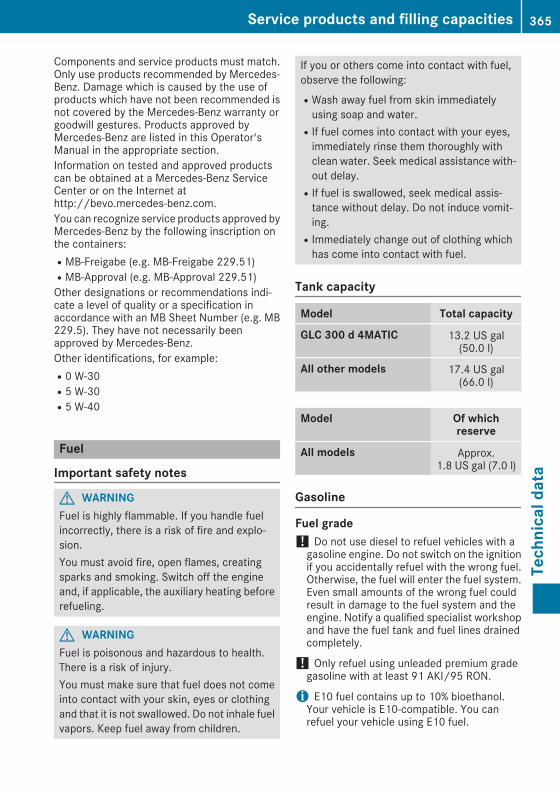
Components and service products must match.Only use products recommended by Mercedes-Benz. Damage which is caused by the use ofproducts which have not been recommended isnot covered by the Mercedes-Benz warranty orgoodwill gestures. Products approved byMercedes-Benz are listed in this Operator'sManual in the appropriate section.Information on tested and approved productscan be obtained at a Mercedes-Benz ServiceCenter or on the Internet athttp://bevo.mercedes-benz.com.You can recognize service products approved byMercedes-Benz by the following inscription onthe containers:RMB-Freigabe (e.g. MB-Freigabe 229.51)RMB-Approval (e.g. MB-Approval 229.51)Other designations or recommendations indi-cate a level of quality or a specification inaccordance with an MB Sheet Number (e.g. MB229.5). They have not necessarily beenapproved by Mercedes-Benz.Other identifications, for example:R0 W-30R5 W-30R5 W-40
Fuel
Important safety notes
G WARNINGFuel is highly flammable. If you handle fuelincorrectly, there is a risk of fire and explo-sion.You must avoid fire, open flames, creatingsparks and smoking. Switch off the engineand, if applicable, the auxiliary heating beforerefueling.
G WARNINGFuel is poisonous and hazardous to health.There is a risk of injury.You must make sure that fuel does not comeinto contact with your skin, eyes or clothingand that it is not swallowed. Do not inhale fuelvapors. Keep fuel away from children.
If you or others come into contact with fuel,observe the following:RWash away fuel from skin immediatelyusing soap and water.RIf fuel comes into contact with your eyes,immediately rinse them thoroughly withclean water. Seek medical assistance with-out delay.RIf fuel is swallowed, seek medical assis-tance without delay. Do not induce vomit-ing.RImmediately change out of clothing whichhas come into contact with fuel.
Tank capacity
Model Total capacity
GLC 300 d 4MATIC 13.2 US gal(50.0 l)
All other models 17.4 US gal(66.0 l)
Model Of whichreserve
All models Approx.1.8 US gal (7.0 l)
Gasoline
Fuel grade! Do not use diesel to refuel vehicles with agasoline engine. Do not switch on the ignitionif you accidentally refuel with the wrong fuel.Otherwise, the fuel will enter the fuel system.Even small amounts of the wrong fuel couldresult in damage to the fuel system and theengine. Notify a qualified specialist workshopand have the fuel tank and fuel lines drainedcompletely.
! Only refuel using unleaded premium gradegasoline with at least 91 AKI/95 RON.
i E10 fuel contains up to 10% bioethanol.Your vehicle is E10-compatible. You canrefuel your vehicle using E10 fuel.
Service products and filling capacities 365
Technicaldata
Z

! Only use the fuel recommended. Operatingthe vehicle with other fuels can lead to dam-age to the fuel system, engine and exhaustsystem.
! Do not use the following:RGasoline with more than 10% ethanolRE100 (100% ethanol)RGasoline with methanolRM100 (100% methanol)RGasoline with metalliferous additivesRDieselDo not mix such fuels with the fuel recom-mended for your vehicle.
! To ensure the longevity and full perform-ance of the engine, only premium-gradeunleaded gasoline must be used.If standard unleaded gasoline is unavailableand you have to refuel with unleaded gasolineof a lower grade, observe the following pre-cautions:ROnly fill the fuel tank to half full with regularunleaded gasoline and fill the rest with pre-mium-grade unleaded gasoline as soon aspossible.RDo not drive at the maximum speed.RAvoid sudden acceleration and enginespeeds over 3,000 rpm.
You will usually find information about the fuelquality on the pump. If you cannot find the labelon the fuel pump, ask the gas station staff.
i For further information, consult a qualifiedspecialist workshop or visithttp://www.mbusa.com (USA only).
As a temporary measure, if the recommendedfuel is not available, you may also use regularunleaded gasoline with an octane rating of87 AKI/91 RON. This may reduce engine per-formance and increase fuel consumption. Avoiddriving at full throttle and sudden acceleration.Never refuel using gasoline with a lower AKI.Information on refueling (Y page 149).
Additives! Operating the engine with fuel additivesadded later can lead to engine failure. Do notmix fuel additives with fuel. This does notinclude additives for the removal and preven-tion of residue buildup. gasoline must only bemixed with additives recommended by
Mercedes-Benz. Comply with the instructionsfor use on the product label.More informationabout recommended additives can beobtained from any authorizedMercedes-BenzCenter.
Mercedes-Benz recommends that you use bran-ded fuels that have additives.The fuel quality available in some countries maynot be sufficient. Residue could build up in thefuel injection system as a result. In such cases,and in consultation with an authorizedMercedes-Benz Center, the fuel may be mixedwith the cleaning additive recommended byMercedes-Benz. You must observe the notesand mixing ratios specified on the container.
Diesel
Fuel gradeG WARNINGIf you mix diesel fuel with gasoline, the flashpoint is lower than that of pure diesel fuel.When the engine is running, exhaust systemcomponents could overheat without beingnoticed. There is a risk of fire.Never refuel with gasoline. Nevermix gasolinewith diesel fuel.
! Refuel only using diesel fuel that conformsto European standard EN590or an equivalentspecification. Fuel that does not conform toEN 590 can lead to increased wear and dam-age the engine and exhaust system.
! Do not use the following:Rmarine dieselRheating oilRbio-dieselRvegetable oilRgasolineRparaffinRkeroseneDo not mix such fuels with diesel fuel and donot use any special additives. Otherwise,engine damage may occur.
! In countries outside the EU, only use low-sulfur Euro diesel with a sulfur content ofunder 50 ppm. Otherwise, the emission con-trol system could be damaged.
366 Service products and filling capacitiesTechnicaldata

You will usually find information about the fuelquality on the pump. If you cannot find the labelon the fuel pump, ask the gas station staff.Information on refueling (Y page 149).
Low outside temperaturesi Diesel fuel with improved cold flow proper-ties is available during the winter months.Further information about fuel properties canbe obtained from oil companies, e.g. at gasstations.
DEF
Important safety notesComply with the important safety notes for ser-vice products when handling DEF (Y page 364).DEF is a water-soluble fluid for the exhaust gasaftertreatment of diesel engines. It is:Rnot poisonousRcolorless and odorlessRnot flammableWhen you open the DEF container, smallamounts of ammonia vapor may be released.Ammonia vapors have a pungent odor and areparticularly irritating to the skin, to mucousmembranes and to the eyes. You may experi-ence a burning sensation in your eyes, nose andthroat. Coughing and watering of the eyes arepossible.Do not inhale ammonia vapors. Fill the DEF tankonly in well-ventilated areas.
Low outside temperaturesDEF freezes at a temperature of approximately-11 †. The vehicle is delivered from the factoryequipped with a DEF preheating system. Winteroperation can thus be guaranteed even at tem-peratures below -11 †.
Additives! Only use DEF in accordance with ISO22241. Do not use additives with DEF and donot dilute DEF with water. This may destroythe BlueTEC exhaust gas aftertreatment sys-tem.
Purity! Impurities in DEF (e.g. due to other serviceproducts, cleaning agents or dust) lead to:Rincreased emission valuesRdamage to the catalytic converterRengine damageRmalfunctions in the BlueTEC exhaust gasaftertreatment system
Assuring the purity of DEF is particularly impor-tant with respect to avoidingmalfunctions in theBlueTEC exhaust gas aftertreatment system.If DEF is pumped out of the DEF tank, e.g. duringrepair work, it must not be returned to the tank.The purity of the fluid can no longer be guaran-teed.
Filling capacities
Model Total capacity
All models 29.1 US qt(27.5 l)
Engine oil
General notes
! Do not use engine oil or an oil filter withspecifications deviating from those expresslyrequired for the prescribed service intervals.Do not change the engine oil or oil filter inorder to set replacement intervals longer thanthose prescribed. This could otherwise causedamage to the engine or exhaust gas after-treatment.Follow the instructions on the service intervaldisplay for changing the engine oil. This could
Service products and filling capacities 367
Technicaldata
Z

otherwise cause damage to the engine orexhaust gas aftertreatment.
When handling engine oil, observe the importantsafety notes on service products (Y page 364).The engine oils are matched to the performanceofMercedes-Benz engines and service intervals.You should therefore only use engine oils and oilfilters that are approved for vehicles with main-tenance systems.For a list of approved engine oils and oil filters,consult an authorized Mercedes-Benz Center.Or visit the websitehttp://bevo.mercedes-benz.com.The table shows which engine oils have beenapproved for your vehicle.
Gasoline engines MB-Freigabe orMB-Approval
All models 229.5, 229.6
Diesel engines MB-Freigabe orMB-Approval
All models 228.51, 229.31,229.51, 229.52
i MB approval is indicated on the oil contain-ers.
Filling capacitiesThe following values refer to an oil changeincluding the oil filter.
Model Capacity
GLC 300 d 4MATIC 6.3 US qt (6.0 l)
All other models 6.9 US qt (6.5 l)
Additives! Do not use any additives in the engine oil.This could damage the engine.
Brake fluid
G WARNINGThe brake fluid constantly absorbs moisturefrom the air. This lowers the boiling point ofthe brake fluid. If the boiling point of the brake
fluid is too low, vapor pockets may form in thebrake system when the brakes are appliedhard. This would impair braking efficiency.There is a risk of an accident.You should have the brake fluid renewed atthe specified intervals.
When handling brake fluid, observe the impor-tant safety notes on service products(Y page 364).The brake fluid change intervals can be found inthe Maintenance Booklet.Only use brake fluid approved by Mercedes-Benz in accordance with MB-Freigabe or MB-Approval 331.0.Information about approved brake fluid can beobtained at any qualified specialist workshop oron the Internet athttp://bevo.mercedes-benz.com.
i Have the brake fluid regularly replaced at aqualified specialist workshop in accordancewith the replacement intervals and thereplacement confirmed in the MaintenanceBooklet.
Coolant
Important safety notes
G WARNINGIf antifreeze comes into contact with hot com-ponents in the engine compartment, it mayignite. There is a risk of fire and injury.Let the engine cool down before you add anti-freeze.Make sure that antifreeze is not spillednext to the filler neck. Thoroughly clean theantifreeze from components before startingthe engine.
! Only add coolant that has been premixedwith the desired antifreeze protection. Youcould otherwise damage the engine.Further information on coolants can be foundin the Mercedes-Benz Specifications for Ser-vice Products, MB BeVo 310.1, e.g. on theInternet at http://bevo.mercedes-benz.com.Or contact a qualified specialist workshop.
! Always use a suitable coolant mixture, evenin countries where high temperatures prevail.
368 Service products and filling capacitiesTechnicaldata

Otherwise, the engine cooling system is notsufficiently protected from corrosion andoverheating.
i Have the coolant regularly replaced at aqualified specialist workshop and the replace-ment confirmed in the Maintenance Booklet.
Comply with the important safety notes for ser-vice products when handling coolant(Y page 364).The coolant is a mixture of water and anti-freeze/corrosion inhibitor. It performs the fol-lowing tasks:RAnti-corrosion protectionRAntifreeze protectionRRaising the boiling pointIf the coolant has antifreeze protection down to-35 ‡ (-37 †), the boiling point of the coolantduring operation is approximately 266 ‡(130 †).The antifreeze concentrate/corrosion inhibitorconcentration in the engine cooling systemshould:Rbe at least 50%. This will protect the enginecooling system against freezing down toapproximately -35 ‡ (-37 †).Rnot exceed 55% (antifreeze protection downto -49 ‡ [-45 †]). Otherwise, heat will not bedissipated as effectively.
Mercedes-Benz recommends an antifreeze/corrosion inhibitor concentrate in accordancewith MB Specifications for Service Products310.1.
i When the vehicle is first delivered, it is filledwith a coolant mixture that ensures adequateantifreeze and anti-corrosion protection.
i The coolant is checked with every mainte-nance interval at a qualified specialist work-shop.
Filling capacities
Model Capacity
GLC 300 d 4MATIC 10.6 US qt (10.0 l)
Mercedes-AMGGLC 43 4MATIC
12.2 US qt (11.5 l)
All other models 9.5 US qt (9.0 l)
Windshield washer system
Important safety notes
G WARNINGWindshield washer concentrate could ignite ifit comes into contact with hot engine compo-nents or the exhaust system. There is a risk offire and injury.Make sure that no windshield washer con-centrate is spilled next to the filler neck.
! Only use washer fluid that is suitable forplastic lamp lenses, e.g. MB SummerFit orMBWinterFit. Unsuitable washer fluid could dam-age the plastic lenses of the headlamps.
! Only MB SummerFit and MB WinterFitwasher fluid should be mixed together. Thespray nozzles may otherwise becomeblocked.
Do not use distilled or de-ionized water. Other-wise, the level sensor may give a false reading.When handling washer fluid, observe the impor-tant safety notes on service products(Y page 364).At temperatures above freezing:X Fill thewasher fluid reservoir with amixture ofwater and windshield washer fluid, e.g. MBSummerFit.
Add 1 part MB SummerFit to 100 parts water.At temperatures below freezing:X Fill thewasher fluid reservoir with amixture ofwater and washer fluid, e.g. MB WinterFit.For the correct mixing ratio refer to the infor-mation on the antifreeze reservoir.
i Add windshield washer fluid, e.g. MB Sum-merFit or MB WinterFit, to the washer fluid allyear round.
Climate control system refrigerant
Important safety notesThe climate control system of your vehicle is fil-led with refrigerant R‑134a.The instruction label regarding the refrigeranttype used can be found on the radiator crossmember.
Service products and filling capacities 369
Technicaldata
Z

! Only the refrigerant R‑134a and the PAG oilapproved by Mercedes-Benz may be used.The approved PAG oil may not be mixed withany other PAG oil that is not approved forR-134a refrigerant. Otherwise, the climatecontrol system may be damaged.
Service work, such as refilling with refrigerant orreplacing component parts, may only be carriedout by a qualified specialist workshop. All appli-cable regulations, as well as SAE standard J639,must be adhered to.Always have work on the climate control systemcarried out at a qualified specialist workshop.
Refrigerant instruction label
Example: refrigerant instruction label: Warning symbol; Refrigerant filling capacity= Applicable standards? PAG oil part numberA Type of refrigerantWarning symbol: advises you about:RPossible dangersRHaving service work carried out at a qualifiedspecialist workshop
Filling capacities
All models
Refrigerant 22.2 ± 0.4 oz(630 ± 10 g)
PAG oil 2.8 oz(80 g)
Vehicle data
General notesPlease note that for the specified vehicle data:Rthe heights specified may vary as a result of:
- tires- load- condition of the suspension- optional equipmentRoptional equipment reduces the maximumpayload.
Observe the information relating to level con-trol:RAIR BODY CONTROL (Y page 173)
Dimensions and weights
Model :Openingheight
;Maximumheadroom
Mercedes-AMG GLC 434MATIC
82.9 in(2106 mm)
75.6 in(1920 mm)
All other mod-els
84.5 in(2146 mm)
78.4 in(1992 mm)
Mercedes-AMGGLC 43 4MATIC
Vehicle length 183.5 in (4661 mm)
Vehicle widthincluding exteriormirrors
82.5 in (2096 mm)
Vehicle height 64.1 in (1629 mm)
370 Vehicle dataTechnicaldata

Mercedes-AMGGLC 43 4MATIC
Wheelbase 113.1 in (2873 mm)
Turning circle 39.7 ft (12.10 m)
Maximum roof load 165 lb (75 kg)
Maximum trunkload
All other models
Vehicle length 183.3 in (4656 mm)
Vehicle widthincluding exteriormirrors
82.5 in (2096 mm)
Vehicle height 65.5 in (1664 mm)
Wheelbase 113.1 in (2873 mm)
Turning circle 38.7 ft (11.80 m)
Maximum roof load 165 lb (75 kg)
Maximum trunkload
220 lb (100 kg)
Trailer tow hitch
Trailer loads
Permissible trailer load, braked (at aminimum gradient-climbing capabilityof 12% from a standstill)
Model
All models 3501 lb (1588 kg)
Maximum drawbar noseweight! Use a drawbar noseweight as close as pos-sible to the maximum permissible nose-weight. Do not use a noseweight of less than50 kg, otherwise the trailer may come loose.Note that the payload and the rear axle loadare reduced by the actual payload.
Towing a trailer is not possible with all models.Further information (Y page 203).The drawbar load reduces the permissible over-all load and rear axle load.
The drawbar load acts from above onto the ballhead on the trailer tow hitch.The trailer drawbar noseweight is not included inthe towing weight.
Model Permissible nose-weight
All models 280 lbs (127 kg)
The actual noseweight may not be higher thanthe value which is given. The value can be foundon the trailer tow hitch or trailer identificationplates. The lowest weight applies.The maximum permissible trailer drawbar nose-weight is the maximum weight with which thetrailer drawbar can be loaded. The permissibletrailer drawbar noseweight is the limit forMercedes-Benz-approved trailer couplings.
Gross rear axle weight rating whentowing a trailerMissing values were not available at time ofgoing to print.
Model Gross axle weightrating
GLC 300 d 4MATIC
Mercedes-AMGGLC 43 4MATIC
2822 lbs (1280 kg)
All other models 2755 lbs (1250 kg)
Ball position of the ball coupling
Trailer tow hitch 371
Technicaldata
Z

When the ball coupling is selected, the followingdimensions must not be exceeded:
: 7.0 in
; 0.625 in
= 1.25 in
372 Trailer tow hitchTechnicaldata